KR20140087032A - Medical dilating instrument and medical dilating instrument set - Google Patents
Medical dilating instrument and medical dilating instrument setDownload PDFInfo
- Publication number
- KR20140087032A KR20140087032AKR1020147014363AKR20147014363AKR20140087032AKR 20140087032 AKR20140087032 AKR 20140087032AKR 1020147014363 AKR1020147014363 AKR 1020147014363AKR 20147014363 AKR20147014363 AKR 20147014363AKR 20140087032 AKR20140087032 AKR 20140087032A
- Authority
- KR
- South Korea
- Prior art keywords
- needle
- guide portion
- guide
- tip
- diameter
- Prior art date
- Legal status (The legal status is an assumption and is not a legal conclusion. Google has not performed a legal analysis and makes no representation as to the accuracy of the status listed.)
- Withdrawn
Links
- 230000000916dilatatory effectEffects0.000title2
- 230000007246mechanismEffects0.000claimsdescription22
- 238000003780insertionMethods0.000claimsdescription13
- 230000037431insertionEffects0.000claimsdescription13
- 238000007789sealingMethods0.000claimsdescription12
- 238000001727in vivoMethods0.000claimsdescription8
- 230000007704transitionEffects0.000claimsdescription5
- 230000001105regulatory effectEffects0.000claimsdescription2
- 238000005452bendingMethods0.000description19
- 238000000034methodMethods0.000description15
- 210000002784stomachAnatomy0.000description13
- 210000003815abdominal wallAnatomy0.000description12
- 230000002093peripheral effectEffects0.000description9
- 210000000245forearmAnatomy0.000description7
- 239000000463materialSubstances0.000description7
- 230000004048modificationEffects0.000description7
- 238000012986modificationMethods0.000description7
- 206010016717FistulaDiseases0.000description6
- 230000003890fistulaEffects0.000description6
- 230000002496gastric effectEffects0.000description6
- 230000015572biosynthetic processEffects0.000description5
- 238000010586diagramMethods0.000description3
- 230000002452interceptive effectEffects0.000description3
- 230000009545invasionEffects0.000description3
- 230000000149penetrating effectEffects0.000description3
- 230000008569processEffects0.000description3
- 239000011347resinSubstances0.000description3
- 229920005989resinPolymers0.000description3
- 238000004804windingMethods0.000description3
- 208000005189EmbolismDiseases0.000description2
- 230000008901benefitEffects0.000description2
- 210000004204blood vesselAnatomy0.000description2
- 238000009940knittingMethods0.000description2
- 230000001681protective effectEffects0.000description2
- 238000011084recoveryMethods0.000description2
- JOYRKODLDBILNP-UHFFFAOYSA-NEthyl urethaneChemical compoundCCOC(N)=OJOYRKODLDBILNP-UHFFFAOYSA-N0.000description1
- PXGOKWXKJXAPGV-UHFFFAOYSA-NFluorineChemical compoundFFPXGOKWXKJXAPGV-UHFFFAOYSA-N0.000description1
- 229920006311Urethane elastomerPolymers0.000description1
- 210000000683abdominal cavityAnatomy0.000description1
- 230000033228biological regulationEffects0.000description1
- 238000004891communicationMethods0.000description1
- 238000012790confirmationMethods0.000description1
- 239000000470constituentSubstances0.000description1
- 238000010276constructionMethods0.000description1
- 230000007423decreaseEffects0.000description1
- 238000005553drillingMethods0.000description1
- 239000013013elastic materialSubstances0.000description1
- 229920001971elastomerPolymers0.000description1
- 230000010102embolizationEffects0.000description1
- 230000001605fetal effectEffects0.000description1
- 229910052731fluorineInorganic materials0.000description1
- 239000011737fluorineSubstances0.000description1
- 230000006698inductionEffects0.000description1
- 238000007918intramuscular administrationMethods0.000description1
- 230000035764nutritionEffects0.000description1
- 235000016709nutritionNutrition0.000description1
- 230000035515penetrationEffects0.000description1
- 230000001012protectorEffects0.000description1
- 238000000926separation methodMethods0.000description1
- 229920002379silicone rubberPolymers0.000description1
- 239000004945silicone rubberSubstances0.000description1
Images


Classifications
- A—HUMAN NECESSITIES
- A61—MEDICAL OR VETERINARY SCIENCE; HYGIENE
- A61B—DIAGNOSIS; SURGERY; IDENTIFICATION
- A61B17/00—Surgical instruments, devices or methods
- A61B17/34—Trocars; Puncturing needles
- A61B17/3415—Trocars; Puncturing needles for introducing tubes or catheters, e.g. gastrostomy tubes, drain catheters
- A—HUMAN NECESSITIES
- A61—MEDICAL OR VETERINARY SCIENCE; HYGIENE
- A61J—CONTAINERS SPECIALLY ADAPTED FOR MEDICAL OR PHARMACEUTICAL PURPOSES; DEVICES OR METHODS SPECIALLY ADAPTED FOR BRINGING PHARMACEUTICAL PRODUCTS INTO PARTICULAR PHYSICAL OR ADMINISTERING FORMS; DEVICES FOR ADMINISTERING FOOD OR MEDICINES ORALLY; BABY COMFORTERS; DEVICES FOR RECEIVING SPITTLE
- A61J15/00—Feeding-tubes for therapeutic purposes
- A61J15/0015—Gastrostomy feeding-tubes
- A61J15/0023—Gastrostomy feeding-tubes inserted by using a sheath
- A—HUMAN NECESSITIES
- A61—MEDICAL OR VETERINARY SCIENCE; HYGIENE
- A61B—DIAGNOSIS; SURGERY; IDENTIFICATION
- A61B17/00—Surgical instruments, devices or methods
- A61B17/34—Trocars; Puncturing needles
- A61B17/3417—Details of tips or shafts, e.g. grooves, expandable, bendable; Multiple coaxial sliding cannulas, e.g. for dilating
- A—HUMAN NECESSITIES
- A61—MEDICAL OR VETERINARY SCIENCE; HYGIENE
- A61B—DIAGNOSIS; SURGERY; IDENTIFICATION
- A61B17/00—Surgical instruments, devices or methods
- A61B17/34—Trocars; Puncturing needles
- A61B17/3494—Trocars; Puncturing needles with safety means for protection against accidental cutting or pricking, e.g. limiting insertion depth, pressure sensors
- A61B17/3496—Protecting sleeves or inner probes; Retractable tips
- A—HUMAN NECESSITIES
- A61—MEDICAL OR VETERINARY SCIENCE; HYGIENE
- A61B—DIAGNOSIS; SURGERY; IDENTIFICATION
- A61B90/00—Instruments, implements or accessories specially adapted for surgery or diagnosis and not covered by any of the groups A61B1/00 - A61B50/00, e.g. for luxation treatment or for protecting wound edges
- A61B90/06—Measuring instruments not otherwise provided for
- A61B2090/062—Measuring instruments not otherwise provided for penetration depth
- A—HUMAN NECESSITIES
- A61—MEDICAL OR VETERINARY SCIENCE; HYGIENE
- A61J—CONTAINERS SPECIALLY ADAPTED FOR MEDICAL OR PHARMACEUTICAL PURPOSES; DEVICES OR METHODS SPECIALLY ADAPTED FOR BRINGING PHARMACEUTICAL PRODUCTS INTO PARTICULAR PHYSICAL OR ADMINISTERING FORMS; DEVICES FOR ADMINISTERING FOOD OR MEDICINES ORALLY; BABY COMFORTERS; DEVICES FOR RECEIVING SPITTLE
- A61J15/00—Feeding-tubes for therapeutic purposes
- A61J15/0026—Parts, details or accessories for feeding-tubes
- A61J15/003—Means for fixing the tube inside the body, e.g. balloons, retaining means
- A61J15/0034—Retainers adjacent to a body opening to prevent that the tube slips through, e.g. bolsters
- A61J15/0038—Retainers adjacent to a body opening to prevent that the tube slips through, e.g. bolsters expandable, e.g. umbrella type
- A—HUMAN NECESSITIES
- A61—MEDICAL OR VETERINARY SCIENCE; HYGIENE
- A61J—CONTAINERS SPECIALLY ADAPTED FOR MEDICAL OR PHARMACEUTICAL PURPOSES; DEVICES OR METHODS SPECIALLY ADAPTED FOR BRINGING PHARMACEUTICAL PRODUCTS INTO PARTICULAR PHYSICAL OR ADMINISTERING FORMS; DEVICES FOR ADMINISTERING FOOD OR MEDICINES ORALLY; BABY COMFORTERS; DEVICES FOR RECEIVING SPITTLE
- A61J15/00—Feeding-tubes for therapeutic purposes
- A61J15/0026—Parts, details or accessories for feeding-tubes
- A61J15/0053—Means for fixing the tube outside of the body, e.g. by a special shape, by fixing it to the skin
Landscapes
- Health & Medical Sciences (AREA)
- Life Sciences & Earth Sciences (AREA)
- General Health & Medical Sciences (AREA)
- Animal Behavior & Ethology (AREA)
- Surgery (AREA)
- Veterinary Medicine (AREA)
- Public Health (AREA)
- Gastroenterology & Hepatology (AREA)
- Engineering & Computer Science (AREA)
- Medical Informatics (AREA)
- Molecular Biology (AREA)
- Heart & Thoracic Surgery (AREA)
- Biomedical Technology (AREA)
- Nuclear Medicine, Radiotherapy & Molecular Imaging (AREA)
- Pathology (AREA)
- Media Introduction/Drainage Providing Device (AREA)
- Medical Preparation Storing Or Oral Administration Devices (AREA)
- Surgical Instruments (AREA)
Abstract
Translated fromKoreanDescription
Translated fromKorean본 발명은 의료용 확장기 및 의료용 확장기 세트에 관한 것이다.The present invention relates to a medical expander and a medical expander set.
인체의 체벽에 천자 바늘을 천자하여 형성된 작은 바늘 구멍(천자 구멍)을 확장하는 확장기가 알려져 있다. 확장기는, 외경이 점증하는 직경 확장부를 갖고 있다. 체벽에 형성한 작은 천자 구멍에 확장기의 선단을 삽입하고, 계속하여 직경 확장부를 천자 구멍에 압입해 나감으로써 천자 구멍은 서서히 확장된다. 천자 구멍이 충분히 확장된 시점에서 확장기를 체벽으로부터 발거하여 카테터 등의 의료 기구를 삽입한다. 이에 의해, 혈관, 복강 또는 위장 등의 체강에 대하여 의료 기구를 경피적으로 삽입할 수 있다.An expander is known which extends a small needle hole (puncture hole) formed by puncturing a puncture needle on the body wall of a human body. The expander has a diameter expanding portion whose outer diameter gradually increases. The distal end of the expander is inserted into a small puncture hole formed in the body wall, and the puncture hole gradually expands by pressing the diameter enlarging portion into the puncture hole. At the point when the puncture hole is fully extended, the expander is released from the body wall and a medical instrument such as a catheter is inserted. Thus, the medical instrument can be percutaneously inserted into a body cavity such as a blood vessel, abdominal cavity, or stomach.
특허문헌 1에는, 직경 확장하는 원추 관부가 형성된 캐뉼라에 천자 바늘을 삽입 관통하여 양자를 연결하여 이루어지는 캐뉼라 바늘(확장기가 달린 천자 바늘)이 기재되어 있다. 유저는, 캐뉼라로부터 돌출된 천자 바늘을 체벽에 천자한 후, 캐뉼라를 유치하고 천자 바늘을 발거한다. 이 캐뉼라에 가이드 와이어를 삽입한 다음, 캐뉼라보다도 대직경이고 또한 긴 확장기를 이 가이드 와이어를 따라 체벽에 압입하여 천자 구멍을 확장한다(특허문헌 1의 도 7을 참조).Patent Literature 1 discloses a cannula needle (a puncture needle with an expander) formed by connecting a puncture needle through a cannula formed with a conical tube portion having a diameter expanding portion, and connecting the two. The user punctures the puncture needle protruding from the cannula onto the body wall, and then the cannula is pulled and the puncture needle is extracted. After the guide wire is inserted into the cannula, a large diameter and longer expander than the cannula is inserted into the body wall along the guide wire to expand the puncture hole (refer to FIG. 7 of Patent Document 1).
특허문헌 2에는, 관상의 확장기에 천자 바늘이 삽입 관통된 진입 장치가 기재되어 있다. 확장기는 천자 바늘보다도 길고 또한 대직경이다. 천자 바늘은 기단부에 헤드부가 형성되어 있다. 확장기의 기단부측으로부터 천자 바늘의 바늘끝을 삽입한 다음, 천자 바늘의 헤드부가 확장기의 기단부에 연결된다. 확장기의 주위에는, 윙을 구비하는 시스가 장착되어 있다. 확장기와 함께 시스를 천자 구멍에 압입한 후, 시스를 유치하고 천자 바늘과 확장기를 발거한다. 그리고, 이 시스에 대하여 카테터 등의 의료 기구를 삽입한다.Patent Document 2 discloses an entry device in which a puncture needle is inserted through a tubular expander. The expander is longer than the puncture needle and has a larger diameter. The puncture needle has a head portion formed at its base end. After inserting the needle tip of the puncture needle from the proximal end side of the expander, the head portion of the puncture needle is connected to the proximal end of the expander. A sheath having a wing is mounted around the expander. After inserting the sheath with the expander into the puncture hole, attract the sheath and remove the puncture needle and the expander. Then, a medical instrument such as a catheter is inserted into the sheath.
환자의 체벽에는 혈관이 그물눈 형상으로 존재하고 있으므로, 의료 기구의 유치 위치를 신중하게 결정할 필요가 있다. 이로 인해, 천자 바늘의 천자 위치에는 높은 정밀도가 요구된다. 한편, 손 기술의 안전을 전제로 한 다음, 의사의 작업 부담의 경감을 위해서, 천자 구멍을 확장하는 손 기술(이하, 확장 손 기술)의 간이화가 요구되고 있다.Since blood vessels are present in a net shape on the patient's body wall, it is necessary to carefully determine the position of the medical instrument. As a result, a high accuracy is required for the puncture site of the puncture needle. On the other hand, after the premise of the safety of the hand technique, in order to alleviate the work load of the doctor, it is required to simplify the hand technique for extending the puncture hole (hereinafter referred to as extended hand technique).
특허문헌 1의 캐뉼라 바늘은, 확장기보다도 작은 치수이며 핸들링성이 좋으므로, 원하는 체표 위치에 고정밀도로 천자 구멍을 형성할 수 있다. 그러나, 천자 바늘의 발거 후에 가이드 와이어를 캐뉼라에 삽입하고, 이 가이드 와이어를 따라 확장기를 압입할 필요가 있는 등, 특허문헌 1의 캐뉼라 바늘을 사용한 확장 손 기술은 공정 수가 많고 번잡하다. 또한, 캐뉼라 바늘의 발거 후의 체벽은 천자 구멍을 메우도록 자기 회복하여 가이드 와이어에 밀착되어버리므로, 가이드 와이어를 거쳐서 확장기를 삽입할 때에는, 가이드 와이어의 방향성을 확인하면서 그 방향으로 삽입해 갈 필요가 있는 등, 손 기술에 숙련을 필요로 하는 경우가 있다.The cannula needle of Patent Document 1 is smaller in size than the expander and has better handleability, so that puncture holes can be formed with high accuracy at a desired body surface position. However, it is necessary to insert the guide wire into the cannula after depression of the puncture needle, and to press the expander along the guide wire. The extended hand technique using the cannula needle of Patent Document 1 requires a lot of steps and is troublesome. In addition, since the body wall after the cannula needle is ejected is self-recovered so as to fill the puncture hole and is brought into close contact with the guide wire, when inserting the expander through the guide wire, it is necessary to check the directionality of the guide wire, In some cases, skilled hands are required.
특허문헌 2의 진입 장치는, 천자 바늘과 확장기가 일체화되어 있고, 체벽에 천자 바늘을 천자한 후에, 계속하여 확장기를 천자 구멍에 압입하는 것이 가능하다. 이로 인해, 확장기를 체벽에 압입하기 전에 가이드 와이어를 미리 천자 구멍에 유치해 둘 필요가 없어서 확장 손 기술이 간이하다. 그러나, 특허문헌 2의 진입 장치는, 천자 바늘과 확장기가 일체화되어 있으므로, 천자 바늘을 원하는 체표 위치에 고정밀도로 천자하는 것이 곤란하다. 유저가 천자 바늘의 근방을 파지한 경우에는, 관성 모멘트가 큰 기단부가 천자 조작을 저해한다. 또한, 유저가 기단부를 파지한 경우에는, 손잡이부터 천자 바늘의 선단까지의 거리가 길어지므로, 역시 천자 바늘을 원하는 체표 위치에 고정밀도로 천자하는 것이 곤란하다.In the entry apparatus of Patent Document 2, the puncture needle and the expander are integrated, and after the puncture needle is punctured on the body wall, the expander can be continuously press-inserted into the puncture hole. This makes it unnecessary to hold the guide wire in the puncture hole before pushing the expander into the body wall, so that the extended hand technique is simple. However, in the entry apparatus of Patent Document 2, since the puncture needle and the expander are integrated, it is difficult to puncture the puncture needle at a desired table position with high accuracy. When the user grasps the vicinity of the puncture needles, the proximal end portion having a large moment of inertia hinders puncture manipulation. Further, when the user grasps the proximal end portion, the distance from the handle to the tip of the puncture needle becomes long, so it is also difficult to puncture the puncture needle at the desired body surface position with high accuracy.
본 발명은 상술한 바와 같은 과제를 감안하여 이루어진 것이며, 천자 구멍을 위치 고정밀도로 형성하고, 또한 계속되는 천자 구멍의 확장 조작을 간이하게 행하는 것이 가능한 의료용 확장기 및 의료용 확장기 세트를 제공하는 것이다.SUMMARY OF THE INVENTION The present invention has been made in view of the above-mentioned problems, and it is an object of the present invention to provide a medical dilator and a medical dilator set capable of forming puncture holes with high accuracy in position and continuing to expand the puncture holes with ease.
본 발명의 의료용 확장기는, 첨예한 바늘끝을 갖는 바늘체와, 선단이 상기 바늘끝보다도 끝이 무디게 형성된 가늘고 긴 형상의 안내부와, 상기 안내부보다도 직경이 굵은 동체부와, 상기 안내부 또는 상기 동체부에 설치되어 선단측으로부터 기단부측을 향하여 직경 확장하는 직경 확장부를 구비하고, 상기 바늘체 및 상기 안내부는, 서로 연결되어 상기 안내부를 따라 상기 바늘체가 근접 배치됨과 함께 상기 바늘끝이 상기 안내부의 상기 선단으로부터 돌출된 천자 상태로부터, 상기 바늘끝이 상기 안내부의 상기 선단보다도 후퇴한 보호 상태로 천이하고, 또한, 상기 보호 상태의 상기 안내부의 기단부에 대하여 상기 동체부가 연결되는 것을 특징으로 한다.The medical dilator of the present invention comprises a needle body having a sharp needle tip, a guide portion having a long end whose tip is dulled from the tip of the needle, a body portion having a diameter larger than that of the guide portion, Wherein the needle body and the guide portion are connected to each other so that the needle body is arranged close to the guide portion and the needle tip is connected to the guide portion, The needle end transitions to a protection state in which the needle tip is retracted from the distal end of the guide portion and the body portion is connected to the proximal end portion of the guide portion in the protected state.
또한, 본 발명의 의료용 확장기 세트는, 첨예한 바늘끝을 갖는 바늘체와, 선단이 상기 바늘끝보다도 끝이 무디게 형성된 가늘고 긴 형상을 이루며 기단부에 장착부를 갖는 안내부와, 상기 안내부보다도 직경이 굵은 동체부와, 상기 안내부 또는 상기 동체부에 설치되어 선단측으로부터 기단부측을 향하여 직경 확장하는 직경 확장부를 포함하고, 상기 바늘체와 상기 안내부와 상기 동체부는 별체로서 구성됨과 함께, 상기 장착부에는 상기 바늘체 또는 상기 동체부가 장착되고, 상기 장착부에 상기 바늘체를 장착함으로써 상기 안내부가 상기 바늘체를 따라 근접 배치되어 상기 바늘끝이 상기 안내부의 상기 선단으로부터 돌출하고, 또한, 상기 바늘체를 탈리한 상기 장착부에 대하여 상기 동체부가 장착되는 것을 특징으로 한다.The medical expander set according to the present invention comprises a needle body having a sharp needle tip, a guide portion having a distal end formed in an elongated shape with a tip end dull than the needle tip and having a mounting portion at a proximal end thereof, And a diameter enlarging portion provided in the guide portion or the body portion and extending diametrically from the tip end toward the proximal end side, wherein the needlepoint portion, the guide portion, and the body portion are formed as separate bodies, Wherein the needle body or the body is attached to the needle body and the needle body is mounted on the mounting portion so that the guide portion is disposed close to the needle body so that the needle tip projects from the tip of the guide portion, And the body part is mounted on the detached mounting part.
상기 발명에 있어서, 천자 상태란, 바늘끝이 안내부의 선단보다도 돌출되어 있으며, 바늘끝을 체벽에 천자 가능한 상태에 있는 것을 말한다. 보호 상태란, 바늘끝이 안내부의 선단으로부터 후퇴된 상태를 말하고, 바늘체가 안내부로부터 발거되어 있는 상태와, 바늘체와 안내부가 연결된 채 상대 이동하여 바늘끝이 안내부의 선단보다도 기단부측으로 이동한 상태를 포함한다.In the above-described invention, the puncture state means that the needle tip protrudes beyond the tip of the guide portion, and the needle tip is in a state capable of puncturing the body wall. The protective state refers to a state in which the needle tip is retracted from the distal end of the guide portion and a state in which the needle needle is withdrawn from the guide portion and a state in which the needle tip is moved relative to the base end portion of the guide portion .
상기 발명에 의하면, 천자 상태에 있는 바늘체의 바늘끝을 체벽에 천자한 후에, 바늘체를 보호 상태로 천이시킨 다음 동체부를 안내부의 기단부에 연결시킬 수 있다. 이로 인해, 바늘끝과 함께 가늘고 긴 형상의 안내부의 선단측을 체벽에 삽입한 상태에서, 체벽으로부터 노출된 기단부에 대하여 동체부를 연결함으로써, 충분한 직경을 갖는 확장기를 구성하는 것이 가능하다. 따라서, 직경이 굵은 동체부가 갖는 관성 모멘트의 크기에 상관없이, 원하는 체표 위치에 대하여 바늘끝을 고정밀도로 천자할 수 있다. 또한, 바늘체가 보호 상태로 천이한 상태에서, 안내부를 가이드로 하여 안전하게 확장기(직경 확장부)를 천자 구멍에 압입할(확장할) 수 있다. 이때, 안내부가 천자 구멍에 유치되어 체벽의 자기 회복이 억제된 상태로부터 확장이 개시되므로, 천자 구멍에 직경 확장부를 용이하게 또한 저침습으로 압입할 수 있다.According to the present invention, after the needle tip of the needle in the puncture state is punctured on the body wall, the needle body can be shifted to the protected state, and then the body portion can be connected to the base end portion of the guide portion. Therefore, it is possible to construct an expander having a sufficient diameter by connecting the body portion to the proximal end portion exposed from the body wall in a state in which the distal end side of the elongated guide portion with the needle tip is inserted into the body wall. Therefore, it is possible to puncture the needle tip with high precision with respect to the desired body surface position regardless of the magnitude of the moment of inertia of the body portion having a large diameter. Further, in a state in which the needle bar body is shifted to the protection state, the expander (diameter expanding portion) can be press-fitted (expanded) into the puncture hole securely by using the guide portion as a guide. At this time, since the guide portion is held in the puncture hole and the self-recovery of the body wall is restrained from being expanded, the enlarged diameter portion can be easily press-inserted into the puncture hole with low invasiveness.
또한, 본 발명의 각종 구성 요소는, 개별적으로 독립된 존재일 필요는 없고, 복수의 구성 요소가 1개의 부재로서 형성되어 있는 것, 하나의 구성 요소가 복수의 부재로 형성되어 있는 것, 어떤 구성 요소가 다른 구성 요소의 일부인 것, 어떤 구성 요소의 일부와 다른 구성 요소의 일부가 중복되어 있는 것 등을 허용한다.In addition, the various components of the present invention need not necessarily be independent of each other, but a plurality of components may be formed as one member, one component may be formed of a plurality of members, Is a part of another component, a part of a component is overlapped with a part of another component, and the like.
본 발명의 의료용 확장기 및 의료용 확장기 세트에 의하면, 천자 구멍을 위치 고정밀도로 형성하고, 또한 계속되는 천자 구멍의 확장 조작을 간이하게 행하는 것이 가능하다.According to the medical expander and the medical expander set of the present invention, it is possible to form the puncture holes with high accuracy and position, and to continue the operation of expanding the puncture holes successively.
상술한 목적 및 그 밖의 목적, 특징 및 이점은, 이하에 설명하는 적합한 실시 형태 및 그것에 부수되는 이하의 도면에 의해 더욱 밝혀진다.
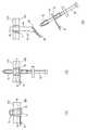
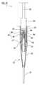
도 1은 본 발명의 제1 실시 형태에 관한 의료용 확장기의 분해 정면도이다.
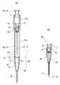
도 2의 (a)는 캐뉼라 바늘의 종단면도이며, (b)는 확장기의 종단면도이다.
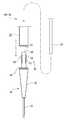
도 3은 시스 확장기의 정면도이다.
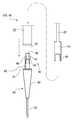
도 4의 (a) 내지 (d)는 시스 확장기에서의 동체부의 선단부의 근방의 제1 내지 제4의 변형예를 도시하는 모식도이다.
도 5의 (a)는 시스의 정면도이며, (b)는 그 우측면도이다.
도 6의 (a)는 위루 카테터에 밀폐 장치를 조합한 상태를 도시하는 정면도이다. (b)는 위루 카테터를 신전시킨 상태를 도시하는 정면도이다.
도 7의 (a) 내지 (c)는 체벽에 위루를 형성하는 제1 내지 제3의 스텝을 도시하는 정면도이다.
도 8의 (a)는 위루 형성의 제4 스텝을 도시하는 정면도, (b)는 시스 확장기가 구성된 상태를 도시하는 정면도, (c) 내지 (d)는 위루 형성의 제5 내지 제6의 스텝을 도시하는 정면도이다.
도 9의 (a) 내지 (c)는 위루 형성의 제7 내지 제9의 스텝을 도시하는 정면도이다.
도 10은 본 실시 형태의 의료용 확장기 세트를 도시하는 설명도이다.
도 11의 (a)는 제2 실시 형태의 캐뉼라 바늘의 분해 정면도이다. (b)는 캐뉼라 바늘의 정면도이다.
도 12의 (a)는 제3 실시 형태의 의료용 확장기를 도시하는 종단면도이며, (b)는 캐뉼라 바늘을 도시하는 종단면도이다.
도 13의 (a)는 제4 실시 형태의 캐뉼라 바늘을 도시하는 종단면도이다. (b)는 바늘끝의 근방의 확대 단면도이다. (c)는 바늘끝 보호 부재가 장착된 바늘체를 도시하는 종단면도이다.
도 14는 제5 실시 형태의 의료용 확장기의 분해 설명도이다.
도 15는 제5 실시 형태의 의료용 확장기의 단면 모식도이다.
도 16은 제6 실시 형태의 의료용 확장기의 분해 설명도이다.
도 17은 제6 실시 형태의 의료용 확장기의 단면 모식도이다.The foregoing and other objects, features and advantages of the present invention will become more apparent from the following detailed description of preferred embodiments thereof with reference to the accompanying drawings.
1 is an exploded front view of a medical expander according to a first embodiment of the present invention.
Fig. 2 (a) is a longitudinal sectional view of the cannula needle, and Fig. 2 (b) is a longitudinal sectional view of the expander.
3 is a front view of the sheath expander.
4 (a) to 4 (d) are schematic diagrams showing first to fourth modified examples in the vicinity of the distal end of the body part in the sheath expander.
Fig. 5 (a) is a front view of the sheath, and Fig. 5 (b) is a right side view thereof.
6 (a) is a front view showing a state in which a whiplash catheter is combined with a sealing device. (b) is a front view showing a state in which the surgeon catheter is inserted.
7 (a) to 7 (c) are front views showing first to third steps for forming a weir on the body wall.
Fig. 8 (a) is a front view showing a fourth step of forming a weir, Fig. 8 (b) is a front view showing a state in which a sheath expander is constructed, Fig.
Figures 9 (a) to 9 (c) are front views showing seventh to ninth steps of forming a weir.
10 is an explanatory view showing the medical expander set of the present embodiment.
11 (a) is an exploded front view of the cannula needle of the second embodiment. (b) is a front view of the cannula needle.
Fig. 12 (a) is a longitudinal sectional view showing the medical expander of the third embodiment, and Fig. 12 (b) is a longitudinal sectional view showing the cannula needle.
Fig. 13 (a) is a longitudinal sectional view showing the cannula needle of the fourth embodiment. Fig. (b) is an enlarged sectional view in the vicinity of the needle tip. (c) is a longitudinal sectional view showing the needle body on which the needle tip protecting member is mounted.
Fig. 14 is an exploded view of the medical expander of the fifth embodiment. Fig.
15 is a sectional schematic view of the medical expander of the fifth embodiment.
16 is an exploded view of the medical expander of the sixth embodiment.
17 is a schematic cross-sectional view of the medical dilator of the sixth embodiment.
이하, 본 발명의 실시 형태를 도면에 기초하여 설명한다. 또한, 모든 도면에 있어서, 동일한 구성 요소에는 동일한 부호를 붙이고, 적절히 설명을 생략한다.DESCRIPTION OF THE PREFERRED EMBODIMENTS Hereinafter, embodiments of the present invention will be described with reference to the drawings. In all the drawings, the same constituent elements are denoted by the same reference numerals, and a description thereof will be omitted.
<제1 실시 형태>≪ First Embodiment >
도 1 내지 도 10을 사용하여, 본 실시 형태의 의료용 확장기(100) 및 의료용 확장기 세트(200), 및 의료용 확장기 세트(200)를 사용하여 체벽에 위루를 형성하는 방법을 설명한다. 먼저, 의료용 확장기(100)의 개요를 설명한다. 이하, 바늘체(10)의 연장 방향을 의료용 확장기(100)의 긴 방향 또는 축방향이라고 하고, 이 긴 방향을 따르는 단면을 의료용 확장기(100)의 종단면이라고 한다.1 to 10, a method of forming a weir on a body wall using the
본 실시 형태의 의료용 확장기(100)는, 첨예한 바늘끝(11)을 갖는 바늘체(10)와, 선단(31)이 바늘끝(11)보다도 끝이 무디게 형성된 가늘고 긴 형상의 안내부(30)와, 안내부(30)보다도 직경이 굵은 동체부(50)를 구비하고 있다. 도 1에 쇄선 화살표로 나타낸 바와 같이, 바늘체(10)와 안내부(30)를 연결함으로써 캐뉼라 바늘(20)이 구성되어, 안내부(30)와 동체부(50)를 연결함으로써 확장기(40)가 구성된다. 확장기(40)는, 선단측으로부터 기단부측을 향하여 직경 확장하는 직경 확장부(42)를 구비하고 있다. 직경 확장부(42)는, 안내부(30) 또는 동체부(50)의 한쪽 또는 양쪽(본 실시 형태에서는 안내부(30))에 설치되어 있다.The
도 2의 (a)에 도시하는 캐뉼라 바늘(20)은, 바늘체(10) 및 안내부(30)가 서로 연결되어 안내부(30)를 따라 바늘체(10)가 근접 배치됨과 함께 바늘끝(11)이 안내부(30)의 선단(31)으로부터 돌출된 천자 상태에 있다. 한편, 도 1에 도시하는 캐뉼라 바늘(20)은, 바늘체(10)가 안내부(30)로부터 기단부측으로 발거되어 바늘끝(11)이 안내부(30)의 선단(31)보다도 후퇴한 보호 상태에 있다. 캐뉼라 바늘(20)은, 천자 상태에서 보호 상태로 천이 가능하다. 캐뉼라 바늘(20)은, 천자 상태로부터 보호 상태를 향하여 불가역적으로 천이해도 되고, 또는 천자 상태와 보호 상태로 가역적으로 천이해도 된다. 본 실시 형태의 캐뉼라 바늘(20)은, 바늘체(10)를 안내부(30)에 대하여 삽입 발출함으로써, 천자 상태와 보호 상태로 가역적으로 천이한다.2 (a), the
안내부(30)는, 캐뉼라 바늘(20)을 구성하여 바늘체(10)의 천자 시에 바늘부(12)와 함께 저침습으로 체벽에 진입하고, 또한 한쪽에서 확장기(40)를 구성하여 직경 확장부(42) 및 동체부(50)를 체벽에 압입할 때의 가이드로서 기능한다. 본 실시 형태의 안내부(30)는 세관부(32)와 직경 확장부(42)로 구성되어 있다. 그리고, 안내부(30)와 바늘체(10)를 조합함으로써 캐뉼라 바늘(20)이 구성된다. 한편, 안내부(30)과 동체부(50)를 조합함으로써 확장기(40)가 구성된다.The
안내부(30)의 세관부(32)는, 바늘체(10)에 연결되어 캐뉼라 바늘(20)을 구성한 경우에 바늘부(12)를 따라 근접 배치되는 부위이다. 본 실시 형태에서는, 관상의 세관부(32)가 바늘체(10)에 주착된 캐뉼라 바늘(20)을 예시하지만, 본 발명은 이것에 한정되지 않는다. 세관부(32) 대신에, 바늘체(10)의 바늘부(12)를 따라 배치되는 막대 형상 부재를 사용해도 된다. 본 실시 형태의 의료용 확장기(100)는 가이드 와이어(90)(도 8을 참조)를 사용하지 않고 누공을 형성할 수 있는 기구이므로, 의료용 확장기(100)를 중공 구조로 하는 것을 반드시 필요로 하지 않는다. 따라서, 안내부(30)의 세관부(32) 대신에, 바늘끝(11)보다도 끝이 무디고 또한 무공의 막대 형상 부재를 바늘부(12)에 추가로 배치해도 된다.The
도 2의 (b)에 도시한 바와 같이, 캐뉼라 바늘(20)로부터 바늘체(10)가 발거되어 보호 상태에 있는 안내부(30)의 기단부(34)에 대하여 동체부(50)가 연결됨으로써 확장기(40)가 구성된다. 안내부(30)에 동체부(50)가 연결된다는 것은, 양자가 직접적으로 결합하고 있는 상태와, 바늘체(10) 또는 다른 부재를 개재시켜서 안내부(30)와 동체부(50)가 간접적으로 결합하고 있는 상태를 포함한다.2 (b), the
다음으로, 의료용 확장기(100)의 상세에 대하여 설명한다. 의료용 확장기(100)는, 체벽에 천자 구멍을 뚫어서 형성하고, 또한 이 천자 구멍을 확장하여 카테터(캐뉼라), 바늘 또는 각종 처치구(부재) 등의 의료 기구를 경피적으로 체강 내에 삽입하기 위한 의료용 디바이스이다. 본 실시 형태의 의료용 확장기(100)는, 복벽 및 위벽에 걸쳐서 누공을 관통 형성하여 위루 카테터(70)(도 10을 참조)를 유치하는 위루 조설술에 적절하게 사용된다.Next, details of the
바늘체(10)는, 바늘부(12)와 헤드부(15)로 구성되어 있다. 바늘체(10)의 기단부(14)에는 헤드부(15)가 형성되어 있다. 바늘체(10)의 기단부(14)란, 바늘끝(11)과 반대측의 소정의 길이 영역을 말한다. 바늘부(12)의 외경은 0.5mm 이상 4mm 이하가 바람직하다. 헤드부(15)의 외경은 바늘끝(11)의 외경보다도 직경이 굵다. 바늘부(12)는 중공 구조를 이루고, 축방향으로 관통하는 내강을 갖고 있다. 헤드부(15)의 외주에는, 직경 방향의 외측 방향에 돌출된 플랜지부(16)가 형성되어 있다. 헤드부(15)는 축방향으로 관통하는 내강을 갖고 있다. 헤드부(15)와 바늘부(12)의 내강은 연통하고 있고, 임의로 가이드 와이어(90)를 삽입 관통 가능하다. 바늘부(12)의 기단부는 헤드부(15)의 내부에서 고착되어 있다.The
도 1, 도 2에 도시한 바와 같이, 안내부(30)의 기단부(34)에는, 동체부(50)의 선단부(52) 또는 바늘체(10)의 헤드부(15)가 끼워 맞춰진다. 본 실시 형태의 안내부(30)의 기단부(34)에는, 동체부(50)의 선단부(52) 또는 바늘체(10)의 헤드부(15)가 택일적으로 끼워 맞춰진다. 구체적으로는, 기단부(34)의 기단부측의 개구부에 해당하는 장착부(35)에, 동체부(50)의 선단부(52) 또는 바늘체(10)의 헤드부(15)가 끼워 맞춰진다. 본 실시 형태의 안내부(30)는, 세관부(32)와 직경 확장부(42)로 이루어진다. 안내부(30)(세관부(32) 및 직경 확장부(42))는, 바늘체(10)(바늘부(12))보다도 직경이 굵은 내강(36)을 구비하는 통 형상을 이루고 있다. 본 실시 형태의 내강(36)은, 세관부(32) 및 직경 확장부(42)의 내부에 걸치는 중공 부분이다. 세관부(32)의 내경은 바늘부(12)의 외경보다도 약간 굵으며, 세관부(32)의 내부에서 바늘부(12)가 미끄럼 이동 가능하다. 안내부(30)가 가늘고 긴 형상이라는 것은, 바늘끝(11)이 형성하는 천자 구멍에 대하여 바늘부(12)와 함께 진입 가능한 가는 직경 부분(본 실시 형태에서의 세관부(32))이 안내부(30)의 선단측에 형성되어 있는 것을 말한다. 또한, 동체부(50)가 안내부(30)보다도 두껍다는 것은, 안내부(30)의 세관부(32)보다도 동체부(50)의 직통부(53)가 대직경인 것을 말한다. 또한, 후술하는 제3 실시 형태의 의료용 확장기(100)와 같이, 안내부(30)의 기단부(34)에 바늘체(10)의 헤드부(15)가 끼워 맞춰진 상태에서, 또한 동체부(50)의 선단부(52)가 기단부(34)에 장착되어도 된다.The
도 2의 (a)에 도시한 바와 같이, 세관부(32)의 선단(31)은 테이퍼 형상으로 직경 축소되어 있다. 선단(31)의 내경은 바늘부(12)의 외경과 동일하며, 바늘체(10)의 둘레면과 세관부(32)의 선단(31)의 둘레면은 원활하게 연속되어 있다. 또한, 세관부(32)의 기단부(33)는 테이퍼 형상으로 직경 확장되어 있고, 직경 확장부(42)의 선단(41)에 걸림 지지되어 빠짐 방지되어 있다. 직경 확장부(42)는, 선단(41)으로부터 기단부(34)를 향하여 연속적으로 직경 확장되어 있다. 기단부(34)는, 직경 확장부(42)의 직경이 굵은 종단부(44)와 동등한 직통 형상이다.As shown in Fig. 2 (a), the
내강(36)에는 덮개(36a)가 설치되어 있다. 덮개(36a)는, 바늘체(10)의 삽입 관통을 허용하고, 또한 보호 상태에서 안내부(30)의 선단(31)으로부터 기단부(34)를 향하는 기류를 규제하는 부재이다. 이에 의해, 덮개(36a)는, 위루 형성 시에 체강(위) 내의 충전 가스가 안내부(30)를 통하여 체외로 누출되는 것을 방지한다. 여기서, 기류를 규제한다는 것은, 실질적으로 기류를 완전히 차단하는 상태 외에, 체강 내의 충전 가스의 누출이 실용적으로 문제가 되지 않을 정도로 작은 유량으로 되어 있는 상태를 말한다.The
덮개(36a)는, 안내부(30)(세관부(32), 기단부(34) 또는 직경 확장부(42))와 동일 재료로 일체 형성된 것이어도 되고, 또는 안내부(30)에 장착하여 사용되는 별도의 부재이어도 된다. 내강(36)에 대한 덮개(36a)의 설치 위치는 특별히 한정되지 않고, 세관부(32)의 내부에 설치해도 되고, 직경 확장부(42) 또는 기단부(34)의 내부에 설치해도 된다. 본 실시 형태의 덮개(36a)는, 안내부(30)의 기단부(34)측을 유입측으로 하고, 선단(31)측을 유출측으로 하는 덕 빌 밸브이다.The
이 외에, 덮개(36a)에는, 안내부(30)의 직경 방향으로 연장되는 축을 중심으로 회동하여 내강(36)을 개폐하는 회동 덮개나, 동일하게 안내부(30)의 직경 방향으로 연장하는 축을 중심으로 왕복 요동하여 내강(36)을 개폐하는 플랩 밸브를 사용해도 된다. 또한, 고무 등의 연질의 탄성 재료로 이루어지고, 바늘부(12) 및 가이드 와이어보다도 대직경의 삽입 관통 구멍이 관통 형성된 색전을 덮개(36a)로 해도 된다. 덮개(36a)는, 천자 상태에서 바늘부(12)를 삽입 관통 가능한 한에 있어서, 안내부(30)의 선단(31)으로부터 기단부(34)를 향하는 기류를 규제하는 것 외에, 반대로 기단부(34)로부터 선단(31)을 향하는 기류도 규제하는 부재이어도 된다.The
도 2의 (a)에 도시하는 천자 상태에 있어서, 바늘체(10)의 바늘부(12)는, 기단부(34)측으로부터 선단(31)측을 향하여 덮개(36a)에 삽입 관통되어 있다. 바늘부(12)가 삽입 관통된 상태에서 덮개(36a)는 개방 상태로 되어 있다. 도 2의 (b)에 도시하는 보호 상태에 있어서, 바늘부(12)는 덮개(36a)로부터 발거되어 덮개(36a)는 자동으로 폐쇄 상태가 된다. 이러한 덮개(36a)를 안내부(30)에 설치함으로써, 바늘부(12)를 발거했을 때의 체강 내로부터의 가스 누설을 방지할 수 있다.2 (a), the
도 2의 (b)에 도시한 바와 같이, 동체부(50)의 선단부(52)는 직통부(53)보다도 소직경이다. 동체부(50)의 선단부(52)가 안내부(30)의 기단부(34)에 끼워 맞춰짐으로써, 직통부(53)의 외주면과 기단부(34)의 외주면은 연속한다. 동체부(50)와 안내부(30)의 연결 경계(B)에서 기단부(34)와 직통부(53)의 사이에 실질적으로 단차는 없다. 이에 의해, 안내부(30)의 선단(31)부터 세관부(32), 직경 확장부(42), 기단부(34) 및 직통부(53)에 걸쳐서, 외경이 단조롭고 또한 연속적으로 증가한다. 이로 인해, 저침습으로 천자 구멍을 확장할 수 있다.As shown in Fig. 2 (b), the
동체부(50)는 안내부(30)보다도 길다. 동체부(50)에는 가이드 와이어(90)의 삽입 관통 구멍(55)이 형성되어 있다. 삽입 관통 구멍(55)은 동체부(50)를 선방 기단부 방향으로 관통하고 있다. 확장기(40)에 있어서 삽입 관통 구멍(55)은 직경 확장부(42)의 내강(36)과 연통한다. 동체부(50)의 기단부에는, 가이드 와이어(90)의 삽입구(57)가 설치되어 있다. 동체부(50)는 캐뉼라 바늘(20)보다도 길며, 동체부(50)의 외주면에는 누공 길이를 측정하기 위한 눈금부(58)가 표시되어 있다(도 1을 참조). 또한, 직경 확장부(42)의 직경이 굵은 측의 종단부(44)의 근방에는 기준 눈금(37)이 표시되어 있다. 눈금부(58)가 나타내는 수치는, 기준 눈금(37)으로부터의 긴 방향의 거리를 나타내고 있다. 확장기(40)가 체벽에 압입되어 직통부(53)가 천자 구멍에 진입했을 때, 체표 위치에서 육안으로 보이는 눈금부(58)의 판독값은, 확장된 천자 구멍(누공)의 깊이를 의미한다.The
의료용 확장기(100)는, 동체부(50)의 직통부(53)의 주위에 장착하여 사용되고, 동체부(50)의 축선 방향을 따라 찢김 또는 분리 가능한 시스(60)를 또한 갖고 있다. 도 3에 도시한 바와 같이 동체부(50)의 주위에 시스(60)가 장착된 상태의 위루 카테터(70)를 시스 확장기라고 호칭한다.The
시스(60)의 선단에는, 동체부(50)와 동일한 직경 또는 동체부(50)보다도 약간 가는 직경의 선세부(62)가 형성되어 있다. 여기서, 선세부(62)가 동체부(50)보다도 가는 직경이라는 것은, 선세부(62)의 외경이 동체부(50)의 외경보다도 작은 것을 말한다. 도 3에 도시한 바와 같이, 본 실시 형태의 시스(60)는, 안내부(30)의 기단부(34)와 동체부(50)의 경계(연결 경계(B))를 피복하고 있다. 시스(60)의 선세부(62)는, 기준 눈금(37) 또는 직경 확장부(42)의 직경이 굵은 측의 종단부(44) 또는 그들 근방에 위치하고 있다. 단, 시스(60)의 선세부(62)가 직경 확장부(42)의 중간부까지 달하고 있어도 된다. 시스(60)의 선세부(62)의 외주면과 직경 확장부(42)의 외주면은 연속하고 있다. 이로 인해, 천자 구멍(누공)에 확장기(40)를 압입할 때, 시스(60)는 원활하게 누공에 진입한다.A
후술하는 위루 형성 방법에 있어서는, 안내부(30)와 동체부(50)의 연결 경계(B)에서의 직경 방향의 단차 및 축방향의 간극이 작은 것이 바람직하다. 이에 의해, 확장기(40)를 체벽에 압입하는 확장 시, 또는 시스(60)를 천자 구멍(H)(도 7을 참조)에 유치하고 확장기(40)를 발거할 때, 이들의 손 기술을 저침습으로 행할 수 있다. 마찬가지로, 시스(60)의 선세부(62)와, 동체부(50) 또는 직경 확장부(42)의 직경 방향의 단차가 작은 것이 바람직하다.It is preferable that the step in the radial direction and the gap in the axial direction at the connection boundary B between the
도 4의 (a) 내지 도 4의 (d)는, 확장기(40)에서의 동체부(50)의 선단부 근방의 제1 내지 제4의 변형예를 도시하는 모식도이다. 이들의 도면에 있어서는, 투명한 시스(60)를 투과하여 육안으로 보이는 동체부(50)를 실선으로 도시하고 있다. 이들의 변형예에 의하면, 확장 시에 선세부(62)가 천자 구멍(H)(도 7을 참조)의 주위벽과 간섭하는 것이 억제된다.Figs. 4A to 4D are schematic diagrams showing first to fourth modified examples in the vicinity of the distal end portion of the
도 4의 (a)의 제1 변형예의 동체부(50)의 직통부(53)와, 안내부(30)의 기단부(34)의 사이에는 직경 축소 방향의 단차, 즉 선단측을 향하여 직경 축소하는 단차가 존재한다. 직통부(53)보다도 기단부(34)는 소직경이다. 시스(60)의 선세부(62)는 기단부(34)에 위치하고 있다. 시스(60)의 선세부(62)의 두께가, 기단부(34)와 직통부(53)의 단차의 내부에 존재하므로, 시스(60)의 선세부(62)가 천자 구멍(H)의 주위벽과 간섭하는 것이 억제되어 있다.A stepped portion in the radial direction reducing direction, that is, a diameter reduced toward the tip side is provided between the
도 4의 (b)의 제2 변형예의 직통부(53)와 기단부(34)의 사이에는 직경 확장 방향의 단차, 즉 선단측을 향하여 직경 확장하는 단차가 존재한다. 직통부(53)보다도 기단부(34)는 대직경이다. 시스(60)의 선세부(62)는 직통부(53)의 하단부, 즉 기단부(34)의 기단부측에 접하고 있다. 확장기(40)가 체벽에 압입될 때, 시스(60)의 선세부(62)의 적어도 일부 두께는, 기단부(34)와 직통부(53)의 단차에 수용된다. 이로 인해, 시스(60)의 선세부(62)가 천자 구멍(H)의 주위벽과 간섭하는 것이 억제된다.Between the
도 4의 (c)의 제3 변형예의 기단부(34)는 축방향(동일 도면의 상하 방향)의 중간부에, 소직경의 조임부(34a)가 형성되어 있다. 직통부(53)의 하단부로부터 조임부(34a)에 걸쳐서 외경은 원활하게 감소하고 있다. 시스(60)의 선세부(62)는 조임부(34a)에 위치하고 있다. 이로 인해, 직경 확장부(42)에서 확장된 천자 구멍(H)의 주위벽과 선세부(62)가 간섭하는 것이 억제되어 있다. 또한, 조임부(34a)의 선단측에 연속하여 경사면(34b)이 형성되어 있다. 경사면(34b)은, 선단측을 향하여 확장하는 역테이퍼 형상이다. 이러한 경사면(34b)을 기단부(34)에 형성함으로써, 천자 구멍(누공)(H)에 시스(60)를 유치하고 확장기(40)를 시스(60)로부터 발거할 때(도 8의 (d)를 참조), 안내부(30)가 선세부(62)에 간섭하지 않는다.The
도 4의 (d)의 제4 변형예의 기단부(34)는, 제2 변형예(도 4의 (b)를 참조)에서의 직통부(53)와 기단부(34)의 사이의 직경 확장 방향의 단차에 경사면(34b)을 설치한 것이다. 경사면(34b)은, 선단측을 향하여 확장하는 역테이퍼 형상이다. 시스(60)의 선세부(62)는, 이 경사면(34b)에 위치하고 있다. 시스(60)의 선세부(62)는 경사면(34b)의 배후에 가려지므로, 시스(60)의 선세부(62)가 천자 구멍(H)의 주위벽과 간섭하는 것이 억제된다. 시스(60)의 선세부(62)가 경사면(34b)에 위치하고 있음으로써, 제3 변형예와 마찬가지로, 천자 구멍(누공)(H)에 시스(60)를 유치하고 확장기(40)를 시스(60)로부터 발거할 때, 안내부(30)가 선세부(62)에 간섭하지 않는다.The
제2 내지 제4의 변형예의 확장기(40)와 같이, 직경 확장부(42)의 최대 외경보다도 작은 가는 직경 영역을 안내부(30)와 동체부(50)의 연결 경계(B) 또는 그 선단측에 형성하고, 선세부(62)가 이 가는 직경 영역에 위치하도록 시스(60)를 동체부(50)에 장착하면 된다.A narrow diameter region smaller than the maximum outer diameter of the
도 5의 (a) 및 (b)에 도시한 바와 같이, 시스(60)는 파지부(66), 밸브부(65) 및 통 형상부(63)로 이루어진다. 통 형상부(63)는 투명한 수지 재료로 이루어진다. 통 형상부(63)에는 하프컷 홈(64)이 형성되어 있다. 하프컷 홈(64)은 통 형상부(63)의 긴 방향의 전체 길이에 걸쳐서 형성되어 있다. 밸브부(65)는 통 형상부(63)의 기단부측의 내주면에 접하고 있다. 밸브부(65)의 기단부측은 파지부(66)에 고정되고, 선단측은 파지부(66)에 대하여 요동 가능하다. 이에 의해, 통 형상부(63)의 기단부측 개구를 개폐 가능하게 또한 기밀하게 폐쇄 유지한다.5 (a) and 5 (b), the
본 실시 형태의 의료용 확장기(100)는, 위루 카테터(70) 및 밀폐 장치(80)(도 6의 (a), (b)를 참조)와 함께 사용된다. 위루 카테터(70)는 위루용 버튼이라고도 한다. 위루 카테터(70)는, 체표로부터 위벽 내부에 걸쳐서 유치되는 카테터이며, 경피적 내시경하 위루 조설술(PEG: Percutaneous Endoscopic Gastrostomy)에 의한 경장 영양 섭취를 가능하게 하는 기구이다. 위루 카테터(70)의 선단에는 가요성의 체내 유치부(72)가 형성되어 있다. 본 실시 형태의 밀폐 장치(80)는, 위루 카테터(70)의 내부에 삽입 관통되어 체내 유치부(72)를 신전 시킴으로써 이 체내 유치부(72)의 최선단부를 시스(60)보다도 가는 직경으로 직경 축소시키는 기구이다. 도 6의 (a)는, 밀폐 장치(80)가 위루 카테터(70)의 내부에 장착된 상태를 도시한다. 도 6의 (b)는, 밀폐 장치(80)가 위루 카테터(70)에 대하여 선단측(동일 도면의 하방)에 가압됨으로써, 밀폐 장치(80)의 선단이 체내 유치부(72)를 하방으로 신전시킨 상태를 도시한다. 체내 유치부(72)는, 일례로서 비벌룬 형식(말레콧식)이다. 위루 카테터(70)는, 누공 내에 삽입 관통되는 직통부(73)와, 그 상부에 형성된 접촉판(75)과, 직통부(73)의 기단부측 개구를 폐색하는 색전(74)을 갖고 있다.The
도 7, 도 8 및 도 9의 각 도면을 사용하여, 본 실시 형태의 의료용 확장기(100)에 의해 체벽에 누공을 형성하여 위루 카테터(70)를 유치하는 방법(위루 형성 방법)을 설명한다.A method of forming a fistula on the body wall by the
우선, 위루 형성의 예비 공정으로서, 도 7의 (a)에 도시한 바와 같이, 천자 구멍의 예정 형성 위치의 주위를 둘러싸도록 하여 복벽(300)과 위벽(310)을 봉합실(320)로 고정해 둔다. 또한, 안내부(30)와 바늘체(10)를 연결하여 캐뉼라 바늘(20)을 구성해 둔다. 바늘체(10)의 바늘끝(11)은 안내부(30)의 선단(31)으로부터 돌출된 천자 상태에 있다. 다음으로, 위루 형성의 제1 스텝에서는, 복벽(300)에 대하여 바늘체(10)를 수직으로 충돌시켜서 바늘끝(11)을 복벽(300)에 천자한다. 본 실시 형태의 캐뉼라 바늘(20)은 동체부(50)를 포함하지 않고, 동체부(50)보다도 길이가 짧은 바늘체(10)와 거의 동등한 전체 길이다. 이로 인해, 천자 구멍의 원하는 예정 형성 위치에 고정밀도로 바늘끝(11)을 천자할 수 있다.7 (a), the
도 7의 (b)에 도시하는 제2 스텝에서는, 또한 캐뉼라 바늘(20)을 압입하고, 바늘끝(11)에 계속하여 안내부(30)의 선단(31)을 천자 구멍(H)에 삽입한다. 이에 의해, 천자 구멍(H)은 안내부(30)의 세관부(32)의 외경까지 확장된다. 안내부(30)의 선단(31)은 위벽(310)의 하면(내면)으로부터 돌출되는 것이 바람직하다. 바꾸어 말하면, 안내부(30)의 세관부(32)는, 복벽(300)과 위벽(310)의 합계 두께보다도 긴 것이 바람직하다.In the second step shown in Fig. 7 (b), the
도 7의 (c)에 도시하는 제3 스텝에서는, 안내부(30)를 천자 구멍(H)에 유치한 채 안내부(30)로부터 바늘체(10)(동일 도면에는 도시하지 않음)를 발거하여 캐뉼라 바늘(20)(동일 도면에는 도시하지 않음)을 보호 상태로 천이시킨다. 이에 의해, 안내부(30)의 장착부(35)가 개구한다. 장착부(35)는, 안내부(30) 중 천자 구멍(H)보다 상방에 노출된 기단부(34)에 형성되어 있다.In the third step shown in Fig. 7C, the needle 10 (not shown in the same figure) is emitted from the
안내부(30)의 내강(36)에는 덮개(36a)가 설치되어 있다. 본 실시 형태의 덮개(36a)는, 안내부(30)의 선단(31)으로부터 기단부(34)를 향하는 기류를 일방적으로 규제하는 덕 빌 밸브이다. 도 7의 (a) 및 (b)의 천자 상태에서는, 바늘체(10)의 바늘부(12)가 덮개(36a)에 삽입 관통되어 있다. 도 7의 (c)에 도시하는 본 실시 형태의 보호 상태에서는, 바늘부(12)가 덮개(36a)로부터 발거되어 있다. 이에 의해, 덮개(36a)는 내강(36)을 폐쇄 유지하고 있다. 체강(위)의 내부에는 대기압보다도 고압의 가스가 충전되어 있다. 이 충전 가스가 위를 주머니 형상으로 팽창시킴으로써, 내시경의 시야는 넓고 안정된 상태로 유지된다. 덮개(36a)는, 제3 스텝 및 그 이후의 공정에 있어서, 안내부(30)를 통하여 충전 가스가 누출되는 것을 방지한다. 후술하는 확장 공정에서 덮개(36a)가 내강(36)을 폐쇄 유지하고 있음으로써, 충전 가스가 확장 공정중에 체강으로부터 누출되는 것이 억제된다.A
도 8의 (a)에 도시하는 제4 스텝에서는, 시스(60)를 장착한 동체부(50)의 선단부(52)를 안내부(30)의 장착부(35)에 장착한다. 시스(60)는 동체부(50)에 대하여 미끄럼 이동 가능하다. 동체부(50)의 선단부(52)를 시스(60)로부터 선단측에 노출시킨 상태에서, 이것을 장착부(35)에 장착한다. 그 후, 시스(60)를 선단측으로 슬라이드시켜서, 그 선세부(62)를 기준 눈금(37) 또는 직경 확장부(42)의 직경이 굵은 측의 종단부(44) 또는 그들의 근방에 맞추는 것이 바람직하다. 이때, 임의로 가이드 와이어(90)를 사용해도 된다. 구체적으로는, 천자 구멍(H)에 유치되어 있는 안내부(30)의 기단부의 개구(장착부(35))에 가이드 와이어(90)를 삽입한 다음, 이 가이드 와이어(90)를 따라 동체부(50)를 장착부(35)에 장착한다. 가이드 와이어(90)는 덮개(36a)에 삽입 관통되고, 안내부(30)의 선단(31)으로부터 돌출된다. 가이드 와이어(90)는 충분히 가늘어, 덮개(36a)와 가이드 와이어(90)의 간극으로부터 위 내의 충전 가스가 크게 누출될 일은 없다.In the fourth step shown in Fig. 8 (a), the
단, 본 실시 형태의 위루 형성에 있어서, 가이드 와이어(90)를 사용하지 않고 동체부(50)의 선단부(52)를 장착부(35)에 장착해도 된다. 도 8의 (b)는, 동체부(50)와 안내부(30)가 조합되어 확장기(40)가 구성된 상태를 도시하고 있다. 동체부(50)의 주위에는 시스(60)가 밀착하여 장착되어 있다. 이때, 동일 도면에 도시한 바와 같이, 확장기(40)(안내부(30))의 선단(31)이 위벽(310)의 하면(내면)으로부터 돌출되어 있고, 세관부(32)의 외경의 천자 구멍(H)이 복벽(300)과 위벽(310)에 걸쳐서 관통 형성되어 있다. 체강(위)의 내부에 달하는 천자 구멍(H)이 하부 구멍으로서 형성되어 있음으로써, 후술하는 제5 내지 제6의 스텝에서 확장기(40)를 원활하게 체벽(복벽(300) 및 위벽(310))에 삽입할 수 있다.However, in the formation of the weft of the present embodiment, the
도 8의 (c) 및 (d)는 확장 공정을 도시하고 있다. 확장의 개시 시점에 있어서, 안내부(30)의 세관부(32)가 천자 구멍(H)에 유치되어 있다. 이로 인해, 복벽(300) 및 위벽(310)의 자기 회복이 억제된 상태에서 확장이 개시된다.Figures 8 (c) and 8 (d) show the expansion process. At the start of the expansion, the
도 8의 (c)에 도시하는 제5 스텝에서는, 동체부(50)를 파지하여 확장기(40)를 천자 구멍(H)에 압입한다. 직경 확장부(42)가 복벽(300) 및 위벽(310)에 진입하여 천자 구멍(H)이 확장된다.In the fifth step shown in Fig. 8 (c), the
도 8의 (d)에 도시하는 제6 스텝에서는, 직경 확장부(42)에 계속하여 동체부(50)를 천자 구멍(H)에 압입한다. 직경 확장부(42)는 위벽(310)으로부터 하방의 체강(위) 내부에 달하고 있다. 시스(60)의 선세부(62)는 직경 확장부(42)와 함께 위벽(310)보다도 하방에 달하고 있다. 천자 구멍(H)의 직경은, 직경 확장부(42)의 최대 외경, 즉 동체부(50)의 직통부(53)의 외경과 동등하게 되어 있다. 체강 내(위 내)에는 내시경(도시하지 않음)을 유치해 두고, 천자 구멍(H)의 근방을 광학적으로 관찰하는 것이 바람직하다. 제6 스텝에서 기준 눈금(37)이 위벽(310)의 하면(위 전방벽)을 통과하여 위 내에 도달한 것을 내시경적으로 확인함으로써, 천자 구멍(H)의 전체 길이가 동체부(50)의 외경과 동일한 직경까지 확장된 것이 확인된다. 또한, 계속하여 확장기(40)를 약간 후퇴시키는 등 하여 기준 눈금(37)을 위 전방벽에 맞춘다. 그 상태에서 체표(복벽(300)의 상면)에서 육안으로 보이는 눈금부(58)의 판독값으로부터, 복벽(300) 및 위벽(310)의 합계 두께가 측정된다. 이 판독값에 기초하여, 위루 카테터(70)(도 9를 참조)의 유효장 크기를 결정한다. 판독값으로부터 5 내지 10mm 정도 긴 유효장 크기를 선택하면 된다. 그 후, 시스(60)를 천자 구멍(H)에 유치하고 확장기(40) 및 가이드 와이어(90)를 발거한다. 이상에 의해 천자 구멍(누공)(H)이 형성된다. 또한, 확장기(40)보다도 먼저, 제5 스텝 또는 제6 스텝에서 가이드 와이어(90)를 발거해도 된다.In the sixth step shown in FIG. 8 (d), the
계속하여, 도 9의 (a)에 도시하는 제7 스텝에서는, 확장된 천자 구멍(H)에 유치된 시스(60)에 대하여 위루 카테터(70)를 삽입한다. 확장기(40)가 발거된 시스(60)에 있어서, 그 통 형상부(63)의 기단부측 개구는 밸브부(65)로 폐쇄 유지되어 있다. 위루 카테터(70)에는 밀폐 장치(80)가 삽입되고, 체내 유치부(72)는 선단측으로 신전되어 직경 축소되어 있다. 이러한 체내 유치부(72)를 시스(60)에 삽입하면, 통 형상부(63)의 하프컷 홈(64)이 기단부측으로부터 파단되어 시스(60)가 찢어진다. 위루 카테터(70)는, 시스(60)를 찢으면서 천자 구멍(H)에 삽입된다. 체내 유치부(72)가 위 내(내시경 하)에서 확인될 때까지, 위루 카테터(70)는 천자 구멍(누공)(H)에 삽입된다. 접촉판(75)은, 확장 후의 천자 구멍(H)보다도 크다.Subsequently, in the seventh step shown in Fig. 9 (a), the
도 9의 (b)에 도시하는 제8 스텝에서는, 위루 카테터(70) 및 밀폐 장치(80)가 천자 구멍(누공)(H)에 삽입되고, 찢어진 시스(60)(동일 도면에는 도시하지 않음)를 천자 구멍(누공)(H)으로부터 발거한다.In the eighth step shown in Fig. 9 (b), the
도 9의 (c)에 도시하는 제9 스텝에서는, 밀폐 장치(80)(동일 도면에서는 도시하지 않음)의 신전 해제를 행하고, 그 후, 밀폐 장치(80)를 위루 카테터(70)로부터 발거한다. 이에 의해, 체내 유치부(72)는 자연 상태까지 직경 확장한다. 자연 상태의 체내 유치부(72)는, 확장 후의 천자 구멍(H)보다도 대직경이다. 체벽(복벽(300) 및 위벽(310))이 접촉판(75)과 체내 유치부(72)에서 끼움 지지됨으로써, 위루 카테터(70)는 천자 구멍(H)으로부터 이탈하지 않고 유치된다. 이에 의해, 위루 카테터 유치가 완성된다. 위루 카테터(70)에 튜브 등의 기구를 삽입하는 경우를 제외하고, 직통부(73)의 기단부측 개구(77)를 색전(74)으로 폐색한다.In the ninth step shown in Fig. 9C, the sealing device 80 (not shown in the same drawing) is released, and then the sealing
도 10은, 이상의 위루 형성 방법에 사용한 의료용 확장기 세트(200)를 도시한 모식도이다. 동일 도면의 좌측이 각 기구의 선단측에 닿는다. 의료용 확장기 세트(200)는, 첨예한 바늘끝(11)을 갖는 바늘체(10)와, 선단이 바늘끝(11)보다도 끝이 무디게 형성된 가늘고 긴 형상을 이루며 기단부에 장착부(35)를 갖는 안내부(30)와, 이 안내부(30)보다도 직경이 굵은 동체부(50)와, 안내부(30) 또는 동체부(50)(본 실시 형태에서는 안내부(30))에 설치되고 선단측으로부터 기단부측을 향하여 직경 확장하는 직경 확장부(42)를 포함한다. 바늘체(10)와 안내부(30)와 동체부(50)는 별체로서 구성되어 있다. 장착부(35)에는 바늘체(10) 또는 동체부(50)가 택일적으로 장착되고, 장착부(35)에 바늘체(10)를 장착함으로써 안내부(30)가 바늘체(10)를 따라 근접 배치되어 바늘끝(11)이 안내부(30)의 선단(31)으로부터 돌출하고, 또한, 바늘체(10)를 이탈시킨 안내부(30)의 장착부(35)에 대하여 동체부(50)가 장착된다(도 2를 참조).Fig. 10 is a schematic diagram showing a medical expander set 200 used in the above-described method for forming a weir. The left side of the same drawing touches the tip side of each mechanism. The medical expander set 200 includes a
그리고, 본 실시 형태의 의료용 확장기 세트(200)는, 동체부(50)의 주위에 장착하여 사용되어서 이 동체부(50)의 축선 방향을 따라 찢기 가능한 시스(60), 위루 카테터(70) 및 밀폐 장치(80)를 포함한다. 즉, 본 실시 형태의 의료용 확장기 세트(200)는 체벽에 위루 카테터를 유치하기 위한 위루 조설 세트이다.The medical dilator set 200 according to the present embodiment includes a
의료용 확장기 세트(200)에 있어서, 바늘체(10)는 보호 케이스(19)에 수납되어 있는 것이 바람직하다. 또한, 의료용 확장기 세트(200)에는 가이드 와이어(90)를 임의로 포함해도 된다. 가이드 와이어(90)를 포함하는 경우에는, 이것을 디스펜서 케이스(도시하지 않음)에 수납해 두는 것이 바람직하다. 또한, 의료용 확장기 세트(200)를 구성하는 상기의 각 기구는, 함께 넣어져서, 또는 개별로 제공된다.In the medical expander set 200, it is preferable that the
또한, 본 발명은 상술한 실시 형태에 한정되지 않고, 본 발명의 목적이 달성되는 한에 있어서의 다양한 변형, 개량 등의 형태도 포함한다.The present invention is not limited to the above-described embodiments, and includes various modifications and improvements as far as the object of the present invention is achieved.
<제2 실시 형태>≪ Second Embodiment >
도 11의 (a)는 본 발명의 제2 실시 형태의 캐뉼라 바늘(20)의 분해 정면도이다. 구체적으로는, 도 11의 (a)는 안내부(30)에 대하여 화살표로 나타내는 방향에 바늘체(10)를 삽입하는 상태를 도시하는 정면도이다. 도 11의 (b)는 안내부(30)와 바늘체(10)가 연결하여 이루어지는 캐뉼라 바늘(20)의 정면도이다. 도 11의 (b)는 캐뉼라 바늘(20)의 천자 상태에 해당하고, 도 11의 (a)는 캐뉼라 바늘(20)의 보호 상태에 해당한다.11 (a) is an exploded front view of a
본 실시 형태의 안내부(30)는 곡관부(38)를 갖고 있는 점에서 제1 실시 형태와 상이하다. 곡관부(38)는 가요성을 갖는 관상체이다. 곡관부(38)는 불소, 우레탄, 실리콘 고무 등의 연질의 수지 재료로 이루어진다. 곡관부(38)의 굽힘 강성은 바늘부(12)의 굽힘 강성보다도 충분히 작다. 곡관부(38)와, 안내부(30)에서의 다른 부분은 동일 재료로 구성되어 있어도 되고, 또는 곡관부(38)를 상기 다른 부분보다도 저강성의 상이한 재료로 제작해도 된다. 곡관부(38)의 중심선은 안내부(30)의 중심선(도 11의 (a)의 상하 방향)에 대하여 만곡 또는 굴곡되어 있다. 본 실시 형태의 세관부(32)는, 기단부측은 제1 실시 형태와 동일한 직선 형상이며, 선단측의 일부 길이가 만곡되어 있다. 세관부(32)의 선단(31)은, 도 11의 (a)에 도시하는 자연 상태(보호 상태)에서, 안내부(30)의 중심선에 대하여 측방, 구체적으로는 대략 직교 방향을 향하고 있다. 안내부(30)에서의 곡관부(38)의 위치는 특별히 한정되지 않는다. 선단(31)을 포함하는 선단부에 곡관부(38)를 형성해도 된다. 또는, 선단(31)을 포함하는 선단부를 직관 형상으로 하고, 안내부(30)의 중간부에 곡관부(38)를 형성해도 된다.The
곡관부(38) 및 세관부(32)는, 직경 확장부(42)의 내강(36)과 연통하고 있다. 도 11의 (a)에 도시한 바와 같이, 안내부(30)의 기단부측의 개구인 장착부(35)에 바늘부(12)의 바늘끝(11)을 삽입한다. 바늘끝(11)은, 내강(36)부터 세관부(32)에 이른다. 또한, 바늘끝(11)이 곡관부(38)에 달하면, 바늘끝(11)은 만곡된 곡관부(38)를 곧게 변형시킨다(도 11의 (b)를 참조). 곡관부(38)를 포함하는 세관부(32)의 길이는 제1 실시 형태의 세관부(32)와 동등하고, 헤드부(15)가 장착부(35)에 장착된 천자 상태에서 바늘끝(11)은 세관부(32)의 선단(31)으로부터 돌출된다.The bending
본 실시 형태와 같이 자연 상태의 세관부(32)의 선단(31)이 안내부(30)의 중심선에 대하여 측방을 향하고 있음으로써, 바늘체(10)를 안내부(30)로부터 발거한 보호 상태에서 선단(31)이 체강벽(위의 후방벽)에 충돌한 경우에 곡관부(38)가 유연하게 만곡된다. 따라서, 확장기(40)의 삽입 깊이가 큰 경우에도, 선단(31)이 체강벽에 강하게 돌출 접촉되지 않는다. 곡관부(38)의 만곡 각도, 즉 곡관부(38)의 후방부의 중심선과 전방부의 중심선이 이루는 각은, 15° 이상 180° 이하, 바람직하게는 45° 이상 120° 이하이다. 상기 각도임으로써, 캐뉼라 바늘(20)의 구성 시에는 곡관부(38) 및 바늘체(10)에 과대한 부하가 발생하지 않고, 또한 확장기(40)의 구성 시에는 체강벽을 충분히 보호할 수 있다.The
<제3 실시 형태>≪ Third Embodiment >
도 12의 (a)는, 본 발명의 제3 실시 형태의 의료용 확장기(100)를 도시하는 종단면도이다. 동일 도면은 캐뉼라 바늘(20)의 보호 상태를 도시하고 있다. 동체부(50)에 주착되는 시스(60)(도 3을 참조)는 도시를 생략하고 있다. 도 12의 (b)는, 본 실시 형태의 캐뉼라 바늘(20)의 천자 상태를 도시하는 종단면도이다.12 (a) is a longitudinal sectional view showing a
본 실시 형태의 동체부(50)의 내부에는 중공의 수용부(56)가 형성되어 있다. 보호 상태에서 바늘체(10)는 수용부(56)에 수용되는 점에서 제1 및 제2의 실시 형태와 상이하다. 본 실시 형태의 의료용 확장기(100)에 있어서는, 안내부(30)의 기단부(34)에 바늘체(10)의 헤드부(15)가 끼워 맞춰진 상태에서, 또한 동체부(50)의 선단부(52)가 기단부(34)에 장착된다.A hollow receiving
바늘체(10)의 기단부(14)에는, 슬라이드부(17)가 측방(도 12 각 도면의 우측 방향)에 돌출되어 형성되어 있다. 슬라이드부(17)는 선방 기단부 방향(각 도면의 상하 방향)으로 연장되는 가늘고 긴 형상을 이루고 있다. 동체부(50)의 직통부(53)에는 슬릿(53a)이 축방향으로 형성되어 있다. 슬라이드부(17)는 슬릿(53a)의 내부에서 축방향으로 미끄럼 이동한다. 직통부(53)의 기단부에는, 수용부(56)의 내경이 직경 확장하는 직경 확장 헤드부(53b)가 형성되어 있다. 슬릿(53a)은, 직경 확장 헤드부(53b)의 중간부부터 선단(51)까지 연장되어 있다. 바늘체(10)는, 플랜지부(16)를 제외하고 동체부(50)의 직통부(53)의 내경보다도 가는 직경이다. 플랜지부(16)의 외경은, 직경 확장 헤드부(53b)의 내경보다도 작고, 직통부(53)의 내경보다도 크다. 플랜지부(16)는 수지 등의 가요성 재료로 구성되어 있고, 직통부(53)의 내부에서는 직통부(53)의 내벽면에 눌려서 휘고, 직경 확장 헤드부(53b)의 내부에서는 자연 상태로 탄성적으로 복원한다. 의사 등의 유저는, 슬라이드부(17)를 조작하여 바늘체(10)를 안내부(30) 및 동체부(50)의 내부에서 미끄럼 이동시킬 수 있다.On the
본 실시 형태의 캐뉼라 바늘(20)은, 보호 상태와 천자 상태로 자유롭게 천이한다. 도 12의 (a)에 도시하는 보호 상태에 있어서, 바늘체(10)의 플랜지부(16)는 직경 확장 헤드부(53b)의 하단부의 단차면(53c)에 걸려 있다. 이 보호 상태에서, 바늘체(10)의 바늘끝(11)은, 동체부(50)의 선단(51)보다도 기단부측에 위치하고 있다. 즉, 바늘체(10)의 바늘부(12)의 전체 길이가 동체부(50)에 수용되어 있다.The
도 12의 (b)에 도시하는 천자 상태에서는, 바늘체(10)의 플랜지부(16)가 안내부(30)의 장착부(35)에 접촉함으로써 바늘체(10)와 안내부(30)가 연결된다. 바늘체(10)의 바늘끝(11)은 안내부(30)의 선단(31)으로부터 돌출된다. 이에 의해 캐뉼라 바늘(20)이 구성된다.12 (b), the
본 실시 형태의 의료용 확장기(100)는, 안내부(30)의 장착부(35)에 바늘체(10)가 장착된 상태에서, 또한 동체부(50)가 장착부(35)에 장착 가능한 점에서 제1 및 제2의 실시 형태와 상이하다. 본 실시 형태의 안내부(30)의 장착부(35)는 계단 형상을 이루고 있고, 장착부(35)에 장착된 플랜지부(16)의 주위에서 동체부(50)의 선단(51)이 요철 끼워 맞춰진다(도 12의 (a)를 참조). 이에 의해, 도 8의 (a)에 도시한 위루 형성의 제4 스텝에 있어서, 안내부(30)에 바늘체(10)가 연결된 상태에서, 동체부(50)의 선단부(52)를 안내부(30)의 장착부(35)와 연결하는 것이 가능하다. 이와 같이 하여, 바늘체(10)를 안내부(30)로부터 발거하지 않고 안내부(30)에 동체부(50)를 연결하여 확장기(40)를 구성한 후에, 도 12의 (a)에 도시한 바와 같이 바늘체(10)를 동체부(50)의 기단부측에 삽입함으로써, 의료용 확장기(100)(캐뉼라 바늘(20))를 보호 상태로 천이시킬 수 있다. 이에 의해, 위루 형성 방법의 손 기술 종료 후에 유저가 바늘체(10)의 바늘끝(11)에 접촉하지 않고 안전하게 확장기(40)를 폐기하는 것이 가능하다.The
<제4 실시 형태>≪ Fourth Embodiment &
도 13의 (a)는, 본 발명의 제4 실시 형태의 캐뉼라 바늘(20)을 도시하는 종단면도이다. 도 13의 (b)는 바늘끝(11)의 근방의 확대 단면도이다. 도 13의 (c)는 바늘끝 보호 부재(39)가 장착된 바늘체(10)를 도시하는 종단면도이다.13 (a) is a longitudinal sectional view showing a
본 실시 형태의 안내부(30)의 내부 또는 주위에는 바늘끝 보호 부재(39)가 장비되어 있다(도 13의 (a)를 참조). 그리고, 천자 상태의 바늘체(10)가 안내부(30)로부터 발거됨으로써 바늘끝 보호 부재(39)가 바늘체(10)에 장착되어 이 바늘끝(11)을 덮는 것을 특징으로 한다(도 13의 (c)를 참조).The needle
바늘끝 보호 부재(39)는, 위루 형성의 제2 스텝(도 7의 (b)를 참조)의 후에 캐뉼라 바늘(20)로부터 바늘체(10)를 발거할 때, 바늘체(10)의 바늘끝(11)을 덮는다. 이에 의해 바늘체(10)를 안전하게 폐기할 수 있다. 바늘끝 보호 부재(39)의 구체적인 형상은 특별히 한정되지 않지만, 본 실시 형태의 바늘끝 보호 부재(39)는 통 형상을 이루고 있다. 바늘끝 보호 부재(39)의 선단측은 개구되어 있고, 기단부측에는 바닥(39a)이 설치되어 있다.The needle
바늘체(10)는, 안내부(30)로부터 발거될 때에 바늘끝 보호 부재(39)와 걸림결합하는 돌기부(18)를 구비하고 있다. 본 실시 형태의 경우, 바늘부(12)의 중간부에 원기둥 형상의 돌기부(18)가 고착되어 있다. 돌기부(18)는, 천자 상태에서 세관부(32)의 내부에 수용되어 있다.The
도 13의 (a)에 도시하는 천자 상태로부터, 동일 도면에 화살표로 나타내는 방향으로 바늘체(10)를 발거하면, 바늘부(12)의 돌기부(18)는 세관부(32)부터 직경 확장부(42)에 이른다. 또한, 바늘체(10)를 발거하면, 돌기부(18)는, 직경 확장부(42)의 내강(36)에 수용된 바늘끝 보호 부재(39)의 내부에 진입하고, 바늘끝 보호 부재(39)의 바닥(39a)에 도달한다. 바닥(39a)에는, 바늘부(12)의 외경보다도 대직경이고, 또한 돌기부(18)의 외경보다도 소직경인 미끄럼 이동 구멍이 형성되어 있다. 따라서, 바늘체(10)를 안내부(30)로부터 충분히 발거하면, 바늘체(10)의 돌기부(18)는 바닥(39a)과 접촉하고, 또한 바늘끝 보호 부재(39)를 밀어올리면서 안내부(30)로부터 이탈한다. 도 13의 (c)는, 이러한 보호 상태를 도시하고 있다.The protruding
<제5 실시 형태>≪ Embodiment 5 >
도 14는 본 발명의 제5 실시 형태의 의료용 확장기(100)의 분해 설명도이다. 동체부(50)는 선단측의 일부만을 도시하고, 기단부측은 도시를 생략하고 있다. 도 14에 있어서는, 안내부(30)의 기단부(34)에 동체부(50)의 선단부(52)를 연결하고, 또한 동체부(50)의 내부에 걸림 보조 부재(82)를 삽입하는 방향을 화살표로 나타내고 있다. 도 15는 본 실시 형태의 의료용 확장기(100)의 단면 모식도이다. 바늘체(10)(도시하지 않음)가 발거되어 보호 상태에 있는 캐뉼라 바늘(즉, 안내부(30))과 동체부(50)가 연결되어 확장기(40)가 구성되어 있다.Fig. 14 is an exploded view of the
본 실시 형태의 의료용 확장기(100)는, 제1 실시 형태와 마찬가지로, 안내부(30)의 기단부(34)에 동체부(50)의 선단부(52) 또는 바늘체(10)(도 1을 참조)의 헤드부(15)가 택일적으로 끼워 맞춰져 있다.The
도 15에 도시한 바와 같이, 본 실시 형태의 의료용 확장기(100)는, 안내부(30)와 동체부(50)를 해제 가능하게 연결하는 로크 기구(88)를 구비하고 있다. 로크 기구(88)는, 서로 연결한 상태의 안내부(30)와 동체부(50)의 분리를 금지하는 수단이다.As shown in Fig. 15, the
보다 구체적으로는, 본 실시 형태의 로크 기구(88)는, 걸림 지지편(46)과 걸림부(59)를 구비하고 있다. 걸림 지지편(46)은, 안내부(30) 또는 동체부(50)의 한쪽에 설치되어 있다. 걸림부(59)는, 안내부(30) 또는 동체부(50)의 다른 쪽에 설치되고, 이 걸림 지지편(46)과 걸림 결합한다. 안내부(30)와 동체부(50)를 서로 연결한 상태에서 걸림 지지편(46)과 걸림부(59)를 걸림 결합시킴으로써, 안내부(30)와 동체부(50)의 이탈이 규제된다. 로크 기구(88)가 안내부(30)와 동체부(50)를 해제 가능하게 연결한다는 것은, 안내부(30)와 동체부(50)가 직접 또는 간접적으로 연결되어 있는 제1 상태와, 양자가 분리 가능한 제2 상태가 로크 기구(88)의 동작에 의해 천이하는 것을 말한다. 도 15에 도시하는 본 실시 형태에서는, 직경 확장부(42)를 포함하는 안내부(30)가 동체부(50)와 분리되는 것을 예시하지만, 본 발명은 이것에 한정되지 않는다. 직경 확장부(42)가 동체부(50)에 설치되어 있는 경우에는, 로크 기구(88)의 동작에 의해 직경 확장부(42)와 세관부(32)(안내부(30))가 분리되어도 된다.More specifically, the
도 15에 도시한 바와 같이, 직경 확장부(42)의 기단부(34)의 개구에는, 통 형상의 연결부(43)가 삽입 고정되어 있다. 직경 확장부(42)와 연결부(43)는 접착되어 있어도 된다. 연결부(43)의 기단부(도 15의 상단부)에는 환상부(45)가 형성되어 있다. 연결부(43) 중 환상부(45)에 인접하는 선단측에 걸림 지지편(46)이 형성되어 있다.As shown in Fig. 15, a
걸림 지지편(46)은, 연결부(43)의 직경 방향의 외측에 돌출된 삼각 갈고리 형상을 이루고 있다. 도 15에 도시한 바와 같이, 걸림 지지편(46)은, 선단(하단부)측의 하측 테이퍼(47)와 기단부(상단부)측의 상측 테이퍼(48)로 구성되어 있다. 또한, 걸림 지지편(46)에 상측 테이퍼(48)를 형성하는 것은 임의이다.The engaging
복수개의 걸림 지지편(46)이 연결부(43)의 주위에 대향하여, 또는 방사상으로 분산하여 배치되어 있다. 개개의 걸림 지지편(46)은, 연결부(43)의 직경 방향의 내측 방향 및 외측 방향으로 돌출 함몰(突沒) 가능하다. 통 형상의 연결부(43)의 내측으로부터 외측 방향으로 걸림 지지편(46)을 가압함으로써, 걸림 지지편(46)의 돌출 높이는 증대한다.A plurality of latching
동체부(50)의 선단부(52)에는 플랜지 통부(54)가 크라우닝 되어 있다. 플랜지 통부(54)의 통 형상의 상단부(걸림부(59))는 내측 방향으로 하향 경사지는 테이퍼 형상을 이루고 있다. 또한, 플랜지 통부(54)는 동체부(50)와 한 재료로 일체로 형성되어 있어도 된다.The
본 실시 형태의 의료용 확장기(100)(확장기(40))는, 동체부(50)에 삽입하여 사용되는 걸림 보조 부재(82)(일부 도시 생략)를 구비하고 있다. 걸림 지지편(46)이 걸림 보조 부재(82)에 의해 직경 방향의 외측 방향으로 가압됨으로써, 걸림 지지편(46)의 돌출 높이는 증대한다. 이에 의해, 걸림 보조 부재(82)를 사용하지 않는 경우와 비교하여, 걸림 보조 부재(82)를 동체부(50)에 삽입함으로써 걸림 지지편(46)이 걸림부(59)에 대하여 보다 깊게 걸림 결합한다. 이에 의해, 걸림 지지편(46)의 하측 테이퍼(47)와 걸림부(59)가 걸림 결합하고, 연결부(43)가 플랜지 통부(54)의 내부에 침입하는 것이 규제된다. 즉, 걸림 보조 부재(82)를 동체부(50)에 삽입함으로써 안내부(30)와 동체부(50)는 로크되고, 걸림 보조 부재(82)를 발거함으로써 안내부(30)와 동체부(50)는 언로크된다. 하측 테이퍼(47)와 걸림부(59)는, 모두 의료용 확장기(100)의 직경 방향의 내측 방향으로 하향 경사지는 테이퍼 형상을 이루고 있다. 바꾸어 말하면, 하측 테이퍼(47)와 걸림부(59)는 동일한 방향으로 경사져 있고, 걸림 지지편(46)을 걸림부(59)에 대하여 선단측에 가압하면, 걸림 지지편(46)은 이 경사 방향을 따라 의료용 확장기(100)의 직경 방향의 내측 방향으로 몰입한다. 이에 의해, 걸림 지지편(46)의 외경이 플랜지 통부(54)의 내경 이하로 변형되고, 걸림 지지편(46)과 걸림부(59)의 걸림 결합의 일부 또는 전부가 해제되어 서로 이탈 가능해진다. 즉, 걸림 보조 부재(82)를 동체부(50)로부터 발거함으로써, 걸림 지지편(46)을 포함하는 연결부(43)의 전체가 플랜지 통부(54)로부터 발거 가능해진다.The medical dilator 100 (expander 40) of the present embodiment is provided with an engagement assisting member 82 (not shown) which is inserted into the
걸림 보조 부재(82)는 막대 형상을 이루고 있다. 걸림 보조 부재(82)의 외경은, 동체부(50)의 삽입 관통 구멍(55)(도 2를 참조) 및 환상부(45)의 내경보다도 작고, 걸림 보조 부재(82)는 삽입 관통 구멍(55) 및 환상부(45)에 삽입 가능하다. 본 실시 형태의 확장기(40)는, 걸림 보조 부재(82)를 삽입하고 있지 않은 상태에서는 로크가 걸려 있지 않아서 안내부(30)와 동체부(50)는 합체 해제가 가능하다.The
<제6 실시 형태>≪ Sixth Embodiment &
도 16은 본 발명의 제6 실시 형태의 의료용 확장기(100)의 분해 설명도이다. 동체부(50)는 선단측의 일부만을 도시하고, 기단부측은 도시를 생략하고 있다. 도 16에 있어서는, 안내부(30)의 기단부(34)에 동체부(50)의 선단부(52)를 연결하고, 또한 동체부(50)의 내부에 해제용 부재(84)를 삽입하는 방향을 화살표로 나타내고 있다. 도 17은 본 실시 형태의 의료용 확장기(100)의 단면 모식도이다. 바늘체(10)(도시하지 않음)가 발거되어 보호 상태에 있는 캐뉼라 바늘(즉, 안내부(30))과 동체부(50)가 연결되어 확장기(40)가 구성되어 있다.16 is an exploded view of a
본 실시 형태의 의료용 확장기(100)는, 안내부(30)와 동체부(50)를 해제 가능하게 연결하는 로크 기구(88)를 구비하는 점에서 제5 실시 형태와 공통된다. 그리고, 해제용 부재(84)의 미삽입 상태에서 안내부(30)와 동체부(50)가 로크되어 있고, 해제용 부재(84)를 동체부(50)에 삽입함으로써 언로크되는 점에서 제5 실시 형태와 상이하다.The
즉, 본 실시 형태의 의료용 확장기(100)는, 동체부(50)에 삽입하여 사용되는 해제용 부재(84)를 구비하고 있다. 그리고, 해제용 부재(84)를 동체부(50)에 삽입함으로써 걸림 지지편(46)과 걸림부(59)의 걸림 결합의 일부 또는 전부가 해제되어 걸림 지지편(46)과 걸림부(59)가 서로 이탈 가능해진다.That is, the
본 실시 형태의 걸림 지지편(46)은, 선단(하단부)측의 단차부(49)와, 기단부(상단부)측의 상측 테이퍼(48)로 구성되어 있다. 단차부(49)는 걸림 지지편(46)의 하단부측의 단부면이며, 연결부(43)의 직경 방향으로 기립하고 있다.The latching
도 17에 도시한 바와 같이, 본 실시 형태의 플랜지 통부(54)의 상단부(걸림부(59))는 내측 방향으로 하향 경사지는 테이퍼 형상이 아니고, 플랜지 통부(54)의 축방향에 대하여 대략 직각으로 기립하고 있는 점에서 제5 실시 형태와 상이하다. 걸림 지지편(46)의 외경은 걸림부(59)의 내경보다도 크다. 걸림 지지편(46)은, 통 형상의 연결부(43)의 직경 방향의 내측 방향 및 외측 방향으로 돌출 함몰 가능하다. 연결부(43)를 직경 방향의 내측 방향으로 가압함으로써 걸림 지지편(46)의 돌출 높이는 감소한다.17, the upper end portion (engaging portion 59) of the
해제용 부재(84)는 막대 형상의 축부(85)와, 이 축부(85)의 선단(하단부)에 형성된 환상의 가압부(86)를 구비하고 있다. 가압부(86)는 축부(85)보다도 대직경이다. 가압부(86)의 외경은 동체부(50)의 삽입 관통 구멍(55)(도 2를 참조)의 내경보다도 작고, 해제용 부재(84)는 동체부(50)에 삽입 가능하다. 가압부(86)의 내경은, 걸림 지지편(46)의 외경보다도 작다. 도 17에 도시한 바와 같이, 안내부(30)와 동체부(50)가 연결되어 확장기(40)가 구성되어 있는 상태에서 동체부(50)에 해제용 부재(84)를 삽입하면, 가압부(86)가 걸림 지지편(46)을 직경 방향의 내측 방향으로 몰입시킴으로써 연결부(43)(걸림 지지편(46))가 플랜지 통부(54)의 내부에 삽입 가능한 직경이 된다. 이에 의해 로크 기구(88)가 언로크되어 안내부(30)와 동체부(50)가 서로 이탈 가능해진다.The releasing
제5 및 제6의 실시 형태의 의료용 확장기(100)에 의하면, 로크 기구(88)에 의해 동체부(50)와 안내부(30)가 분리 불가능하게 연결되므로, 확장 손 기술의 사이에 직경 확장부(42)가 불안정해지는 일이 없다. 의사는, 확장기(40)의 동체부(50)로부터 걸림 보조 부재(82)를 발거, 또는 해제용 부재(84)를 동체부(50)에 삽입하여 로크 기구(88)를 언로크함으로써, 동체부(50)와 안내부(30)를 간이하게 분리할 수 있다. 이에 의해, 예를 들어 도 8의 (b)와 같이 확장기(40)가 일단 구성된 후라도, 동체부(50)를 용이하게 분리하여 안내부(30)나 가이드 와이어(90)를 미세하게 손 기술 조작하는 것이 가능하다.According to the
제5 및 제6의 실시 형태에서는, 안내부(30)나 동체부(50)는 별체의 걸림 보조 부재(82)나 해제용 부재(84)를 사용하여 로크 기구(88)를 해제 조작하는 것을 예시하였다. 단, 본 발명은 이것에 한정되지 않는다. 예를 들어 제6 실시 형태의 제1 변형예로서, 손가락의 조작에 의해 걸림 지지편(46)과 걸림부(59)의 걸림 결합을 해제 가능하게 구성해도 된다. 구체적으로는, 걸림부(59)에 걸림 결합한 상태의 걸림 지지편(46)을 삽입 관통하는 슬릿을 동체부(50)의 둘레면에 형성해도 된다. 이 슬릿으로부터 면하는 걸림 지지편(46)을 손가락에 의해 동체부(50)의 내측에 압입함으로써, 걸림 지지편(46)과 걸림부(59)의 걸림 결합이 해제되고, 연결부(43)가 플랜지 통부(54)로부터 분리 가능해진다.In the fifth and sixth embodiments, the guiding
로크 기구(88)의 해제 조작을 행한 경우에 동체부(50)와 안내부(30)가 확실하게 분리되므로, 동체부(50)와 안내부(30)를 서로 이격시키는 방향으로 가압하는 탄성 부재(도시하지 않음)를 설치해도 된다. 구체적으로는, 제6 실시 형태의 제2 변형예로서, 환상의 가압부(86)의 내부에 탄성 부재(권취 스프링: 도시하지 않음)를 장착하면 된다. 해제용 부재(84)를 동체부(50)에 삽입하여 가압부(86)의 하단부가 걸림 지지편(46)을 직경 방향의 내측으로 가압할 때, 이 권취 스프링은 자연 길이보다도 압축된 상태가 된다. 이에 의해, 걸림 지지편(46)과 걸림부(59)의 걸림 결합이 해제되었을 때, 이 권취 스프링이 환상부(45) 또는 상측 테이퍼(48)의 상단부를 탄성적으로 하방으로 압박하고, 연결부(43)가 플랜지 통부(54)로부터 발거되는 것이 보조된다.The
상기 각 실시 형태의 캐뉼라 바늘(20)에 의하면, 위루 형성 방법의 손 기술에 제공된 바늘체(10)를 안전하게 폐기하는 것이 가능하다.According to the
상기 실시 형태는, 이하의 기술 사상을 포함하는 것이다.The above embodiment includes the following technical idea.
(1) 첨예한 바늘끝을 갖는 바늘체와, 선단이 상기 바늘끝보다도 끝이 무디게 형성된 가늘고 긴 형상의 안내부와, 상기 안내부보다도 직경이 굵은 동체부와, 상기 안내부 또는 상기 동체부에 설치되고 선단측으로부터 기단측을 향하여 직경 확장하는 직경 확장부를 구비하고, 상기 바늘체 및 상기 안내부는, 서로 연결되어 상기 안내부를 따라 상기 바늘체가 근접 배치됨과 함께 상기 바늘끝이 상기 안내부의 상기 선단으로부터 돌출된 천자 상태로부터, 상기 바늘끝이 상기 안내부의 상기 선단보다도 후퇴한 보호 상태로 천이하고, 또한, 상기 보호 상태의 상기 안내부의 기단부에 대하여 상기 동체부가 연결되는 것을 특징으로 하는 의료용 확장기;(1) A knitting machine comprising: a needle body having a sharp needle tip; a guide portion having a tip end whose tip is bluntly formed at an end thereof; a body portion having a diameter larger than that of the guide portion; Wherein the needle body and the guide portion are connected to each other so that the needle body is arranged close to the guide portion and that the needle tip extends from the tip end of the guide portion to the distal end of the guide portion A medical expander in which the needle end transitions from a protruded puncture state to a protection state retracted from the distal end of the guide portion and the body portion is connected to the base end portion of the guide portion in the protected state;
(2) 상기 바늘체의 기단부에 헤드부가 형성되어 있고, 상기 안내부의 상기 기단부에, 상기 동체부의 선단부 또는 상기 바늘체의 상기 헤드부가 택일적으로 끼워 맞춰지는 상기 (1)에 기재된 의료용 확장기;(2) The medical expander according to (1), wherein a head portion is formed at a proximal end portion of the needle body, and a distal end portion of the body portion or the head portion of the needle body is selectively fitted to the proximal end portion of the guide portion;
(3) 상기 안내부는, 상기 바늘체보다도 직경이 굵은 내강을 구비하는 통 형상을 이루고 있는 상기 (1) 또는 (2)에 기재된 의료용 확장기;(3) The medical expander according to (1) or (2), wherein the guide portion has a tubular shape having a lumen having a larger diameter than the needle body;
(4) 상기 바늘체의 삽입 관통을 허용하고 또한 상기 보호 상태에서 상기 안내부의 상기 선단으로부터 상기 안내부의 상기 기단부를 향하는 기류를 규제하는 밸브체가, 상기 안내부의 상기 내강에 설치되어 있는 것을 특징으로 하는 상기 (3)에 기재된 의료용 확장기;(4) A valve element is provided in the inner lumen of the guide portion for permitting insertion of the needle body and regulating the flow of air from the tip end of the guide portion toward the base end portion of the guide portion in the protection state. A medical expander according to (3);
(5) 상기 동체부의 주위에 장착하여 사용되고, 상기 동체부의 축선 방향을 따라 찢기 또는 분리 가능한 시스를 더 갖는 상기 (1) 내지 (4) 중 어느 한 항에 기재된 의료용 확장기;(5) The medical expander according to any one of (1) to (4), further comprising a sheath which is mounted around the body part and is torn or separable along the axial direction of the body part;
(6) 상기 직경 확장부가 상기 안내부에 설치되어 있고, 또한 상기 시스가 상기 안내부와 상기 동체부의 경계를 피복하고 있는 상기 (5)에 기재된 의료용 확장기;(6) The medical expander according to (5), wherein the diameter expanding portion is provided in the guide portion, and the sheath covers the boundary between the guide portion and the body portion;
(7) 상기 안내부의 선단은 가요성을 갖는 곡관부인 상기 (1) 내지 (6) 중 어느 한 항에 기재된 의료용 확장기;(7) The medical expander according to any one of (1) to (6), wherein the distal end of the guide portion is a flexible bent portion.
(8) 상기 동체부의 내부에 중공의 수용부가 형성되어 있고, 상기 보호 상태에서 상기 바늘체가 상기 수용부에 수용되는 상기 (1) 내지 (7) 중 어느 한 항에 기재된 의료용 확장기;(8) The medical expander according to any one of (1) to (7), wherein a hollow receiving portion is formed in the body portion and the needle is received in the receiving portion in the protected state;
(9) 상기 안내부에 바늘끝 보호 부재가 장비되어 있고, 상기 천자 상태의 상기 바늘체가 상기 안내부로부터 발거됨으로써 상기 바늘끝 보호 부재가 상기 바늘체에 장착되어 상기 바늘끝을 덮는 것을 특징으로 하는 상기 (1) 내지 (7) 중 어느 한 항에 기재된 의료용 확장기;(9) The needlepoint protecting member is provided on the guide portion, and the needlepoint protecting member is mounted on the needle body and covers the needlepoint by ejecting the needlepoint body from the guide portion. A medical expander according to any one of (1) to (7) above;
(10) 첨예한 바늘끝을 갖는 바늘체와, 선단이 상기 바늘끝보다도 끝이 무디게 형성된 가늘고 긴 형상을 이루고 기단에 장착부를 갖는 안내부와, 상기 안내부보다도 직경이 굵은 동체부와, 상기 안내부 또는 상기 동체부에 설치되고 선단측으로부터 기단측을 향하여 직경 확장하는 직경 확장부를 포함하고, 상기 바늘체와 상기 안내부와 상기 동체부는 별체로서 구성됨과 함께, 상기 장착부에는 상기 바늘체 또는 상기 동체부가 장착되고, 상기 장착부에 상기 바늘체를 장착함으로써 상기 안내부가 상기 바늘체를 따라 근접 배치되어 상기 바늘끝이 상기 안내부의 상기 선단으로부터 돌출하고, 또한, 상기 바늘체를 이탈한 상기 장착부에 대하여 상기 동체부가 장착되는 것을 특징으로 하는 의료용 확장기 세트;(10) A knitting machine comprising: a needle bar having a sharp needle tip; a guide part having a tip end formed in an elongated shape with a tip end dulled and having a mounting part at a base end; a body part having a diameter larger than that of the guide part; And a diameter enlarging portion provided on the body portion and extending diametrically from a distal end side to a proximal end side, wherein the needle body, the guide portion and the body portion are formed as separate bodies, and the attachment portion is provided with the needle body or the body Wherein the needle portion is attached to the mounting portion so that the guide portion is disposed close to the needle body so that the needle tip protrudes from the tip end of the guide portion, A medical expander set having a body part attached thereto;
(11) 상기 동체부의 주위에 장착하여 사용되고 상기 동체부의 축선 방향을 따라 찢기 가능한 시스를 더 포함하는 상기 (10)에 기재된 의료용 확장기 세트;(11) The medical expander set according to (10), further comprising a sheath which is mounted around the body part and can be torn along the axial direction of the body part;
(12) 선단에 가요성의 체내 유치부가 형성된 위루 카테터와, 상기 체내 유치부를 신전시킴으로써 상기 체내 유치부를 상기 시스보다도 가는 직경으로 직경 축소시키는 밀폐 장치를 더 포함하는 상기 (11)에 기재된 의료용 확장기 세트.(12) A medical expander set as set forth in (11), further comprising: a whirri catheter having a flexible inner body portion formed at its tip; and a sealing device for expanding the inner body portion to reduce the inner diameter of the body to a smaller diameter than the sheath.
상기 실시 형태는, 또한 이하의 기술 사상을 포함하는 것이다.The above embodiment also includes the following technical idea.
(i) 상기 안내부와 상기 동체부를 해제 가능하게 연결하는 로크 기구를 더 구비하는 상기 (1) 내지 (7) 중 어느 한 항에 기재된 의료용 확장기;(i) the medical expander according to any one of (1) to (7), further comprising a lock mechanism releasably connecting the guide portion and the body portion;
(ii) 상기 로크 기구가, 상기 안내부 또는 상기 동체부의 한쪽에 설치된 걸림 지지편과, 상기 안내부 또는 상기 동체부의 다른 쪽에 설치되고 상기 걸림 지지편과 걸림 결합하는 걸림부를 구비하고, 상기 안내부와 상기 동체부를 서로 연결한 상태에서 상기 걸림 지지편과 상기 걸림부를 걸림 결합시킴으로써 상기 안내부와 상기 동체부의 이탈이 규제되는 상기 (i)에 기재된 의료용 확장기;(ii) the locking mechanism includes a latching piece provided on one side of the guide portion or the body portion, and a latching portion provided on the other side of the guide portion or the body portion and engaged with the latching piece, (I) the medical expander according to (i), wherein the detachment of the guide part and the body part is restricted by engaging the engaging piece with the engaging part while the body part is connected to each other;
(iii) 상기 동체부에 삽입하여 사용되는 걸림 보조 부재를 더 구비하고, 상기 걸림 보조 부재를 상기 동체부에 삽입함으로써 상기 걸림 지지편이 상기 걸림부에 대하여 보다 깊게 걸림 결합하고, 또한 상기 걸림 보조 부재를 상기 동체부로부터 발거함으로써 상기 걸림 결합의 일부 또는 전부가 해제되어 상기 걸림 지지편과 상기 걸림부가 서로 이탈 가능해지는 상기 (ii)에 기재된 의료용 확장기;(iii) an engaging assistant member inserted and used in the body part, wherein the engaging assisting member is inserted into the body part so that the engaging supporting piece engages with the engaging part more deeply, (Ii) the medical expander according to (ii), wherein part or all of the engaging engagement is released by releasing the engaging piece from the body part so that the engaging piece and the engaging part can be separated from each other;
(iv) 상기 동체부에 삽입하여 사용되는 해제용 부재를 더 구비하고, 상기 해제용 부재를 상기 동체부에 삽입함으로써 상기 걸림 지지편과 상기 걸림부의 상기 걸림 결합의 일부 또는 전부가 해제되어 상기 걸림 지지편과 상기 걸림부가 서로 이탈 가능해지는 상기 (ii)에 기재된 의료용 확장기.(iv) a releasing member inserted and used in the body part, and a part or all of the engaging part of the engaging piece and the engaging part is released by inserting the releasing member into the body part, The medical expander according to (ii) above, wherein the supporting piece and the engaging portion can be separated from each other.
본 출원은, 2011년 10월 31일에 출원된 일본 출원 일본 특허 출원 제2011-239229호를 기초로 하는 우선권을 주장하고, 그 개시의 전부를 본 명세서에 도입한다.This application is based upon and claims the benefit of priority from Japanese Patent Application No. 2011-239229, filed on October 31, 2011, the entire disclosure of which is incorporated herein by reference.
Claims (16)
Translated fromKorean상기 바늘체 및 상기 안내부는, 서로 연결되어 상기 안내부를 따라 상기 바늘체가 근접 배치됨과 함께 상기 바늘끝이 상기 안내부의 상기 선단으로부터 돌출된 천자 상태로부터, 상기 바늘끝이 상기 안내부의 상기 선단보다도 후퇴한 보호 상태로 천이하고, 또한,
상기 보호 상태의 상기 안내부의 기단부에 대하여 상기 동체부가 연결되는 것을 특징으로 하는 의료용 확장기.A needle body having a sharp needle tip, a guide portion having an elongated tip whose tip has a length less than that of the needle tip, a body portion having a diameter larger than that of the guide portion, and a guide portion provided on the guide portion or the body portion, And a diameter enlarging portion extending in the diameter direction from the base end side to the base end side,
Wherein the needle body and the guide portion are connected to each other so that the needle body is arranged close to the guide portion and the needle tip protrudes from the tip end of the guide portion so that the needle tip is retracted from the tip of the guide portion Transition to the protection state, and further,
And the body part is connected to the proximal end of the guide part in the protected state.
상기 안내부의 상기 기단부에, 상기 동체부의 선단부 또는 상기 바늘체의 상기 헤드부가 택일적으로 끼워 맞춰지는 의료용 확장기.The needle bar according to claim 1, wherein a head portion is formed at a base end portion of the needle bar,
And a distal end portion of the trunk portion or the head portion of the needle body is alternatively fitted to the proximal end portion of the guide portion.
상기 걸림 보조 부재를 상기 동체부에 삽입함으로써 상기 걸림 지지편이 상기 걸림부에 대하여 보다 깊게 걸림 결합하고, 또한 상기 걸림 보조 부재를 상기 동체부로부터 발거함으로써 상기 걸림 결합의 일부 또는 전부가 해제되어 상기 걸림 지지편과 상기 걸림부가 서로 이탈 가능해지는 의료용 확장기.[10] The apparatus according to claim 9, further comprising: a latching assisting member inserted into the body part,
The latching assisting member is engaged with the latching portion more deeply by inserting the latching assisting member into the body portion and the latching assisting member is released from the latching body portion so that part or all of the latching engagement is released, And the supporting piece and the engaging portion can be separated from each other.
상기 해제용 부재를 상기 동체부에 삽입함으로써 상기 걸림 지지편과 상기 걸림부의 상기 걸림 결합의 일부 또는 전부가 해제되어 상기 걸림 지지편과 상기 걸림부가 서로 이탈 가능해지는 의료용 확장기.The portable terminal according to claim 9, further comprising a releasing member inserted into the body part,
Wherein the releasing member is inserted into the body part, so that part or all of the engaging engagement of the engaging piece and the engaging part is released so that the engaging piece and the engaging part can be separated from each other.
상기 바늘체와 상기 안내부와 상기 동체부는 별체로서 구성됨과 함께, 상기 장착부에는 상기 바늘체 또는 상기 동체부가 장착되고, 상기 장착부에 상기 바늘체를 장착함으로써 상기 안내부가 상기 바늘체를 따라 근접 배치되어 상기 바늘끝이 상기 안내부의 상기 선단으로부터 돌출하고, 또한, 상기 바늘체를 이탈한 상기 장착부에 대하여 상기 동체부가 장착되는 것을 특징으로 하는 의료용 확장기 세트.A guiding portion having a distal end with an elongated shape having a tip end which is more dull than the needle tip and having a mounting portion at its base end, a body portion having a diameter larger than that of the guiding portion, And a diameter enlarging portion provided in the body portion and extending in diameter from the tip side toward the base end side,
Wherein the needle body, the guide portion, and the body portion are configured as a separate body, the needle body or the body portion is mounted on the mounting portion, and the needle body is mounted on the mounting portion so that the guide portion is disposed close to the needle body Wherein the needle tip protrudes from the tip end of the guide portion and the body portion is attached to the attachment portion that has disengaged from the needle body.
Applications Claiming Priority (3)
| Application Number | Priority Date | Filing Date | Title |
|---|---|---|---|
| JPJP-P-2011-239229 | 2011-10-31 | ||
| JP2011239229 | 2011-10-31 | ||
| PCT/JP2012/006968WO2013065292A1 (en) | 2011-10-31 | 2012-10-31 | Medical dilating instrument and medical dilating instrument set |
Publications (1)
| Publication Number | Publication Date |
|---|---|
| KR20140087032Atrue KR20140087032A (en) | 2014-07-08 |
Family
ID=48191667
Family Applications (1)
| Application Number | Title | Priority Date | Filing Date |
|---|---|---|---|
| KR1020147014363AWithdrawnKR20140087032A (en) | 2011-10-31 | 2012-10-31 | Medical dilating instrument and medical dilating instrument set |
Country Status (5)
| Country | Link |
|---|---|
| EP (1) | EP2774596A4 (en) |
| JP (1) | JP6101206B2 (en) |
| KR (1) | KR20140087032A (en) |
| CN (1) | CN103945818B (en) |
| WO (1) | WO2013065292A1 (en) |
Families Citing this family (11)
| Publication number | Priority date | Publication date | Assignee | Title |
|---|---|---|---|---|
| JP6326211B2 (en)* | 2013-10-01 | 2018-05-16 | 住友ベークライト株式会社 | Gastrostomy tube and gastrostomy catheter replacement kit |
| JP6412483B2 (en)* | 2015-10-30 | 2018-10-24 | クリエートメディック株式会社 | Medical expansion device |
| KR102163628B1 (en)* | 2015-11-18 | 2020-10-08 | 경희대학교 산학협력단 | Catheter Of Salivary Glands, Salivary Glands Treating Kit, Dilator of Salivary Ductal Orifice, Dilator of Salivary Duct, And Dilator Set For Treating Salivary Glands |
| JP6399061B2 (en)* | 2016-08-31 | 2018-10-03 | 住友ベークライト株式会社 | Dilator |
| JP6588676B2 (en)* | 2017-03-24 | 2019-10-09 | 朝日インテック株式会社 | Dilator |
| WO2019078361A1 (en) | 2017-10-20 | 2019-04-25 | テルモ株式会社 | Storage container, packaging member, and medical instrument set |
| JP6881367B2 (en)* | 2018-03-22 | 2021-06-02 | 住友ベークライト株式会社 | Dilator |
| JP7606660B2 (en)* | 2019-02-01 | 2024-12-26 | ニプロ株式会社 | Small animal puncture tool |
| US12279793B2 (en) | 2019-10-16 | 2025-04-22 | Fresenius Kabi Deutschland Gmbh | Cannula device |
| CN111743779B (en)* | 2020-06-11 | 2023-04-11 | 湘南学院附属医院 | Auxiliary tube feeding device and method for medical nasogastric feeding tube for gastrointestinal surgical nursing |
| DE102020207365A1 (en)* | 2020-06-15 | 2021-12-16 | Siemens Healthcare Gmbh | Threading support device for threading an object into a guide device |
Family Cites Families (18)
| Publication number | Priority date | Publication date | Assignee | Title |
|---|---|---|---|---|
| US3653388A (en)* | 1969-12-04 | 1972-04-04 | Battelle Development Corp | Catheter insertion trocar |
| JPS63246178A (en) | 1987-04-01 | 1988-10-13 | 古川 勇一 | Apuncture needle equipped with dilator for imaging blood vessel |
| US4889118A (en)* | 1988-06-20 | 1989-12-26 | Schwiegerling Paul E | Catheter-insertion forceps |
| US4978334A (en)* | 1988-09-08 | 1990-12-18 | Toye Frederic J | Apparatus and method for providing passage into body viscus |
| US6641564B1 (en)* | 2000-11-06 | 2003-11-04 | Medamicus, Inc. | Safety introducer apparatus and method therefor |
| DE60330661D1 (en)* | 2002-05-10 | 2010-02-04 | Tyco Healthcare | EINFÜHRDICHTUNGSANORDNUNG |
| JP4257943B2 (en)* | 2002-07-29 | 2009-04-30 | アークレイ株式会社 | Puncture unit and puncture member removal tool |
| CN1780599A (en)* | 2003-04-28 | 2006-05-31 | 住友电木株式会社 | catheter set for fistula |
| US7479150B2 (en)* | 2003-09-19 | 2009-01-20 | Tyco Healthcare Group Lp | Trocar insertion apparatus |
| US20060089526A1 (en)* | 2004-10-21 | 2006-04-27 | Medical Instrument Development Laboratories, Inc. | Self-sealing closure for an ophthalmic cannula |
| EP2150187A2 (en) | 2007-04-18 | 2010-02-10 | Access Scientific, Inc. | Access device |
| ES2677323T3 (en)* | 2007-06-22 | 2018-08-01 | Medical Components, Inc. | Bushing for removable sheath assembly with hemostatic valve |
| JP2009072344A (en)* | 2007-09-20 | 2009-04-09 | Top:Kk | Gastrostoma tube insertion assist |
| JP5377944B2 (en)* | 2007-11-30 | 2013-12-25 | 住友ベークライト株式会社 | Gastrostomy sheath, sheathed dilator, gastrostomy sheath with insertion aid, gastrostomy catheter kit |
| US20110041854A1 (en)* | 2009-08-18 | 2011-02-24 | Julia Suzanne Rasor | Everting device and method for tracheostomy |
| JP5352395B2 (en)* | 2009-09-24 | 2013-11-27 | 日本コヴィディエン株式会社 | Organ fixture and gastrostomy catheter set |
| JP5990103B2 (en)* | 2009-12-23 | 2016-09-07 | アルコン リサーチ, リミテッド | Ophthalmic valved trocar cannula |
| JP2011206179A (en)* | 2010-03-29 | 2011-10-20 | Fuji Systems Corp | Gastrostomy instrument and gastrostomy method |
- 2012
- 2012-10-31KRKR1020147014363Apatent/KR20140087032A/ennot_activeWithdrawn
- 2012-10-31WOPCT/JP2012/006968patent/WO2013065292A1/enactiveApplication Filing
- 2012-10-31EPEP12845047.5Apatent/EP2774596A4/ennot_activeWithdrawn
- 2012-10-31CNCN201280053842.2Apatent/CN103945818B/enactiveActive
- 2012-10-31JPJP2013541626Apatent/JP6101206B2/enactiveActive
Also Published As
| Publication number | Publication date |
|---|---|
| EP2774596A1 (en) | 2014-09-10 |
| WO2013065292A1 (en) | 2013-05-10 |
| JP6101206B2 (en) | 2017-03-22 |
| JPWO2013065292A1 (en) | 2015-04-02 |
| CN103945818A (en) | 2014-07-23 |
| EP2774596A4 (en) | 2015-07-08 |
| CN103945818B (en) | 2016-08-24 |
Similar Documents
| Publication | Publication Date | Title |
|---|---|---|
| KR20140087032A (en) | Medical dilating instrument and medical dilating instrument set | |
| US11241227B2 (en) | Lead puncture needle | |
| JP3796514B2 (en) | Medical device provided with a retractable puncture needle and method for manufacturing the medical device | |
| US4869717A (en) | Gas insufflation needle with instrument port | |
| JP4506834B2 (en) | Medical needle device | |
| CN100515512C (en) | Safety trocar with progressive cutting tip guard and air jet tissue deflector | |
| JP4038524B2 (en) | Medical instrument and internal organ fixing method | |
| JP6138921B2 (en) | Catheter assembly | |
| CN101204601A (en) | indwelling needle assembly | |
| US20130310750A1 (en) | Safety needle | |
| JPS6060830A (en) | Trocal assembly | |
| EP1923003A1 (en) | Tissue biopsy needle device | |
| JPWO2009041057A1 (en) | Medical instruments | |
| JPWO2016152379A1 (en) | Catheter assembly | |
| CN106102815A (en) | Stabilizing and guiding device for accessing an implanted access interface and related methods | |
| US20150209078A1 (en) | Veress needle | |
| JP2011182986A (en) | Insertion assist tool for organ fixation device | |
| WO2017073454A1 (en) | Medical expansion instrument | |
| GB2428201A (en) | Tracheostomy instrument | |
| WO2014162381A1 (en) | Indwelling catheter and catheter assembly | |
| US9572597B2 (en) | Optical trocar tip protector | |
| JP5632224B2 (en) | Gastrostomy dilator | |
| JP5441565B2 (en) | Indwelling needle syringe | |
| JP2532420Y2 (en) | Laparoscopic trocar | |
| JP3725795B2 (en) | Trocar mantle |
Legal Events
| Date | Code | Title | Description |
|---|---|---|---|
| PA0105 | International application | Patent event date:20140528 Patent event code:PA01051R01D Comment text:International Patent Application | |
| PG1501 | Laying open of application | ||
| A201 | Request for examination | ||
| PA0201 | Request for examination | Patent event code:PA02012R01D Patent event date:20170725 Comment text:Request for Examination of Application | |
| PC1202 | Submission of document of withdrawal before decision of registration | Comment text:[Withdrawal of Procedure relating to Patent, etc.] Withdrawal (Abandonment) Patent event code:PC12021R01D Patent event date:20181119 | |
| WITB | Written withdrawal of application |