KR20140086997A - A package for smoking articles - Google Patents
A package for smoking articlesDownload PDFInfo
- Publication number
- KR20140086997A KR20140086997AKR1020147011877AKR20147011877AKR20140086997AKR 20140086997 AKR20140086997 AKR 20140086997AKR 1020147011877 AKR1020147011877 AKR 1020147011877AKR 20147011877 AKR20147011877 AKR 20147011877AKR 20140086997 AKR20140086997 AKR 20140086997A
- Authority
- KR
- South Korea
- Prior art keywords
- unit
- cartridge unit
- hinge
- package
- cartridge
- Prior art date
- Legal status (The legal status is an assumption and is not a legal conclusion. Google has not performed a legal analysis and makes no representation as to the accuracy of the status listed.)
- Withdrawn
Links
- 230000000391smoking effectEffects0.000titleclaimsabstractdescription266
- 238000000034methodMethods0.000claimsabstractdescription106
- 230000014759maintenance of locationEffects0.000claimsdescription47
- 230000008878couplingEffects0.000claimsdescription42
- 238000010168coupling processMethods0.000claimsdescription42
- 238000005859coupling reactionMethods0.000claimsdescription42
- 230000004308accommodationEffects0.000claimsdescription39
- 230000000717retained effectEffects0.000claimsdescription9
- 238000003780insertionMethods0.000claimsdescription5
- 230000037431insertionEffects0.000claimsdescription5
- 230000013011matingEffects0.000claimsdescription4
- 230000000903blocking effectEffects0.000description60
- 238000007373indentationMethods0.000description37
- 241000208125NicotianaSpecies0.000description6
- 235000002637Nicotiana tabacumNutrition0.000description6
- 230000008901benefitEffects0.000description6
- 230000007935neutral effectEffects0.000description6
- 230000009471actionEffects0.000description4
- 230000036961partial effectEffects0.000description4
- 239000000356contaminantSubstances0.000description3
- 238000004519manufacturing processMethods0.000description3
- 239000000463materialSubstances0.000description3
- 230000004044responseEffects0.000description3
- 239000000853adhesiveSubstances0.000description2
- 230000001070adhesive effectEffects0.000description2
- 235000019506cigarNutrition0.000description2
- 230000000670limiting effectEffects0.000description2
- 230000007246mechanismEffects0.000description2
- 238000003860storageMethods0.000description2
- 239000004743PolypropyleneSubstances0.000description1
- 229910000831SteelInorganic materials0.000description1
- XAGFODPZIPBFFR-UHFFFAOYSA-NaluminiumChemical compound[Al]XAGFODPZIPBFFR-UHFFFAOYSA-N0.000description1
- 229910052782aluminiumInorganic materials0.000description1
- 235000019504cigarettesNutrition0.000description1
- 238000011109contaminationMethods0.000description1
- 230000000994depressogenic effectEffects0.000description1
- 238000011161developmentMethods0.000description1
- 230000018109developmental processEffects0.000description1
- 238000006073displacement reactionMethods0.000description1
- 239000013013elastic materialSubstances0.000description1
- 238000000605extractionMethods0.000description1
- 238000012986modificationMethods0.000description1
- 230000004048modificationEffects0.000description1
- 239000002991molded plasticSubstances0.000description1
- 238000004806packaging method and processMethods0.000description1
- 239000004033plasticSubstances0.000description1
- -1polypropylenePolymers0.000description1
- 229920001155polypropylenePolymers0.000description1
- 238000003825pressingMethods0.000description1
- 230000008569processEffects0.000description1
- 230000001681protective effectEffects0.000description1
- 230000002829reductive effectEffects0.000description1
- 230000002441reversible effectEffects0.000description1
- 239000010959steelSubstances0.000description1
Images


Classifications
- A—HUMAN NECESSITIES
- A24—TOBACCO; CIGARS; CIGARETTES; SIMULATED SMOKING DEVICES; SMOKERS' REQUISITES
- A24F—SMOKERS' REQUISITES; MATCH BOXES; SIMULATED SMOKING DEVICES
- A24F15/00—Receptacles or boxes specially adapted for cigars, cigarettes, simulated smoking devices or cigarettes therefor
- A24F15/12—Receptacles or boxes specially adapted for cigars, cigarettes, simulated smoking devices or cigarettes therefor for pocket use
- B—PERFORMING OPERATIONS; TRANSPORTING
- B65—CONVEYING; PACKING; STORING; HANDLING THIN OR FILAMENTARY MATERIAL
- B65D—CONTAINERS FOR STORAGE OR TRANSPORT OF ARTICLES OR MATERIALS, e.g. BAGS, BARRELS, BOTTLES, BOXES, CANS, CARTONS, CRATES, DRUMS, JARS, TANKS, HOPPERS, FORWARDING CONTAINERS; ACCESSORIES, CLOSURES, OR FITTINGS THEREFOR; PACKAGING ELEMENTS; PACKAGES
- B65D85/00—Containers, packaging elements or packages, specially adapted for particular articles or materials
- B65D85/07—Containers, packaging elements or packages, specially adapted for particular articles or materials for compressible or flexible articles
- B65D85/08—Containers, packaging elements or packages, specially adapted for particular articles or materials for compressible or flexible articles rod-shaped or tubular
- B65D85/10—Containers, packaging elements or packages, specially adapted for particular articles or materials for compressible or flexible articles rod-shaped or tubular for cigarettes
- B65D85/1009—Containers, packaging elements or packages, specially adapted for particular articles or materials for compressible or flexible articles rod-shaped or tubular for cigarettes provided with proffering means
- A—HUMAN NECESSITIES
- A24—TOBACCO; CIGARS; CIGARETTES; SIMULATED SMOKING DEVICES; SMOKERS' REQUISITES
- A24F—SMOKERS' REQUISITES; MATCH BOXES; SIMULATED SMOKING DEVICES
- A24F15/00—Receptacles or boxes specially adapted for cigars, cigarettes, simulated smoking devices or cigarettes therefor
- A24F15/12—Receptacles or boxes specially adapted for cigars, cigarettes, simulated smoking devices or cigarettes therefor for pocket use
- A24F15/16—Receptacles or boxes specially adapted for cigars, cigarettes, simulated smoking devices or cigarettes therefor for pocket use with means for offering
- B—PERFORMING OPERATIONS; TRANSPORTING
- B65—CONVEYING; PACKING; STORING; HANDLING THIN OR FILAMENTARY MATERIAL
- B65D—CONTAINERS FOR STORAGE OR TRANSPORT OF ARTICLES OR MATERIALS, e.g. BAGS, BARRELS, BOTTLES, BOXES, CANS, CARTONS, CRATES, DRUMS, JARS, TANKS, HOPPERS, FORWARDING CONTAINERS; ACCESSORIES, CLOSURES, OR FITTINGS THEREFOR; PACKAGING ELEMENTS; PACKAGES
- B65D85/00—Containers, packaging elements or packages, specially adapted for particular articles or materials
- B65D85/07—Containers, packaging elements or packages, specially adapted for particular articles or materials for compressible or flexible articles
- B65D85/08—Containers, packaging elements or packages, specially adapted for particular articles or materials for compressible or flexible articles rod-shaped or tubular
- B65D85/10—Containers, packaging elements or packages, specially adapted for particular articles or materials for compressible or flexible articles rod-shaped or tubular for cigarettes
- B—PERFORMING OPERATIONS; TRANSPORTING
- B65—CONVEYING; PACKING; STORING; HANDLING THIN OR FILAMENTARY MATERIAL
- B65D—CONTAINERS FOR STORAGE OR TRANSPORT OF ARTICLES OR MATERIALS, e.g. BAGS, BARRELS, BOTTLES, BOXES, CANS, CARTONS, CRATES, DRUMS, JARS, TANKS, HOPPERS, FORWARDING CONTAINERS; ACCESSORIES, CLOSURES, OR FITTINGS THEREFOR; PACKAGING ELEMENTS; PACKAGES
- B65D85/00—Containers, packaging elements or packages, specially adapted for particular articles or materials
- B65D85/07—Containers, packaging elements or packages, specially adapted for particular articles or materials for compressible or flexible articles
- B65D85/08—Containers, packaging elements or packages, specially adapted for particular articles or materials for compressible or flexible articles rod-shaped or tubular
- B65D85/12—Containers, packaging elements or packages, specially adapted for particular articles or materials for compressible or flexible articles rod-shaped or tubular for cigars
Landscapes
- Engineering & Computer Science (AREA)
- Mechanical Engineering (AREA)
- Packaging Of Annular Or Rod-Shaped Articles, Wearing Apparel, Cassettes, Or The Like (AREA)
Abstract
Translated fromKoreanDescription
Translated fromKorean본 출원은 끽연 물품용 패키지에 관한 것이다. 게다가, 본원은 또한 끽연 물품들을 포함하는 카트리지 유닛에 장착하기 위한 힌지 유닛, 힌지 유닛에 부착되도록 구성된 끽연 물품들을 포함하기 위한 카트리지 유닛, 끽연 물품용 패키지의 끽연 물품 홀더, 복수의 카트리지 유닛을 유지하도록 구성된 홀더, 및 끽연 물품용 패키지에 끽연 물품들을 장착하는 방법에 관한 것이다.
The present application relates to packages for smoking articles. In addition, the subject matter also provides a hinge unit for mounting to a cartridge unit including smoking articles, a cartridge unit for containing smoking articles configured to be attached to the hinge unit, a smoking article holder for a smoking article package, And a method for mounting smoking articles on a package for a smoking article.
끽연 물품용 보호 패키지들 또는 컨테이너들이 공지되어 있으며, 끽연 물품을 손상 및/또는 오염으로부터 보호하기 위해 담배 산업에서 광범위하게 사용되고 있다. 그러한 보호 패키지는 일반적으로, 복수의 끽연 물품을 수용하는 강성 하우징을 포함하고, 강성 하우징은 본체와, 본체에 대하여 개구를 중심으로 힌지결합되어 개구를 노출시키고 또한 본체 내에 수용된 끽연 물품에의 접근을 허용하는 덮개를 포함한다. 그러나, 본체 내에 수용되며 개구에서만 노출되는 끽연 물품을 파지하는 것은 어려울 수 있다.
Protection packages or containers for smoking articles are known and have been extensively used in the tobacco industry to protect smoking articles from damage and / or contamination. Such a protective package generally comprises a rigid housing for receiving a plurality of smoking articles, the rigid housing comprising a body and a hinged connection hingedly about the opening with respect to the body to provide access to the smoking article contained within the body, Allowable cover. However, it may be difficult to grasp a smoking article contained in the main body and exposed only in the opening.
상기 내용을 고려해서, 본 발명은 다른 무엇보다 상기에 언급한 문제점들을 극복하거나 또는 실질적으로 완화하는 끽연 물품용 패키지를 제공하려는 것이다.
In view of the above, the present invention intends to provide a package for a smoking article which overcomes or substantially alleviates the above-mentioned problems among others.
본 발명의 일 양태에 따르면, 물품들을 수용할 수 있는 카트리지 유닛, 및 상기 카트리지 유닛에 부착 가능한 힌지 유닛을 포함하는 끽연 물품용 패키지가 제공되고, 상기 힌지 유닛은, 상기 카트리지 유닛이 그 개방 상태에 있을 때 상기 카트리지 유닛에 수용된 물품들에 접근할 수 있도록, 상기 힌지 유닛이 상기 카트리지 유닛에 부착될 때 상기 카트리지 유닛을 폐쇄 상태와 개방 상태 사이에서 이동시킬 수 있게 하도록 구성된다.
According to one aspect of the present invention, there is provided a package for a smoking article comprising a cartridge unit capable of accommodating items and a hinge unit attachable to the cartridge unit, the hinge unit comprising: And to move the cartridge unit between the closed and open states when the hinge unit is attached to the cartridge unit, so as to be able to access the articles contained in the cartridge unit when the hinge unit is present.
상기 카트리지 유닛은 제 1 하우징부 및 제 2 하우징부를 포함할 수 있다. 상기 제 1 하우징부는, 상기 힌지 유닛이 상기 카트리지 유닛에 부착될 때, 상기 제 2 하우징부에 대하여 폐쇄 상태와 개방 상태 사이에서 이동하도록 구성될 수 있다.
The cartridge unit may include a first housing part and a second housing part. The first housing portion may be configured to move between a closed state and an open state with respect to the second housing portion when the hinge unit is attached to the cartridge unit.
상기 힌지 유닛은, 상기 힌지 유닛이 상기 카트리지 유닛에 부착될 때, 상기 힌지 유닛을 중심으로 한 상기 제 1 하우징부 및 상기 제 2 하우징부의 이동을 안내하도록 구성될 수 있다.
The hinge unit may be configured to guide movement of the first housing part and the second housing part about the hinge unit when the hinge unit is attached to the cartridge unit.
상기 힌지 유닛은 서로에 대하여 이동 가능한 제 1 힌지 요소 및 제 2 힌지 요소를 포함할 수 있다. 상기 제 1 하우징부는 상기 제 1 힌지 요소에 부착 가능할 수 있으며 상기 제 2 하우징부는 상기 제 2 힌지 요소에 부착 가능할 수 있다.
The hinge unit may include a first hinge element and a second hinge element movable relative to each other. The first housing part may be attachable to the first hinge element and the second housing part may be attachable to the second hinge element.
상기 제 2 힌지 요소는, 상기 힌지 유닛이 상기 카트리지 유닛에 부착될 때 상기 제 2 하우징부가 상기 힌지 유닛의 회전 축선을 중심으로 회전할 수 있도록, 상기 힌지 유닛의 회전 축선을 중심으로 회전 가능할 수 있다.
The second hinge element may be rotatable about an axis of rotation of the hinge unit so that the second housing part rotates about the axis of rotation of the hinge unit when the hinge unit is attached to the cartridge unit .
상기 힌지 유닛은 중심축(central shaft)을 더 포함할 수 있으며, 상기 제 1 및 제 2 힌지 요소는 상기 중심축 둘레로 연장된다.
The hinge unit may further include a central shaft, and the first and second hinge elements extend around the central axis.
상기 제 1 힌지 요소는 상기 중심축 둘레로 회전 가능할 수 있다.
The first hinge element may be rotatable about the central axis.
상기 제 1 힌지 요소는 숄더(shoulder)를 구비할 수 있고, 상기 중심축은 2개의 단부 정지부에 의해 상기 숄더를 수용하는 리세스를 구비할 수 있다. 상기 숄더는, 상기 제 1 힌지 요소가 상기 중심축을 중심으로 회전될 때, 상기 숄더가 상기 단부 정지부들에 인접해서 상기 중심축을 중심으로 한 상기 제 1 힌지 요소의 회전을 제한하도록, 상기 2개의 단부 정지부 사이에서 상기 리세스 내에서 슬라이드 가능할 수 있다.
The first hinge element may have a shoulder and the central axis may include a recess for receiving the shoulder by two end stops. Wherein the shoulder is configured to limit rotation of the first hinge element about the central axis adjacent the end stops when the first hinge element is rotated about the central axis, And can be slidable within the recess between the stops.
상기 단부 정지부들 중 하나 및 상기 숄더는, 상기 중심축을 중심으로 한 상기 제 1 힌지 요소의 회전을 막기 위해 상기 숄더가 상기 측면에 인접할 때, 서로에 대항하여 놓이도록 구성되는 보유 요소들에 대면해 있을 수 있다.
Wherein one of the end stops and the shoulder are configured to face the retaining elements configured to rest against each other when the shoulder is adjacent the side to prevent rotation of the first hinge element about the central axis It can be done.
상기 카트리지 유닛은 상기 카트리지 유닛에 수용된 하나 또는 그 초과의 물품을 보유하도록 구성되는 물품 홀더를 더 포함할 수 있다.
The cartridge unit may further include an article holder configured to hold one or more articles contained in the cartridge unit.
상기 제 1 하우징부는 상기 물품 홀더에 대하여 이동하도록 구성될 수 있다.
The first housing part may be configured to move relative to the article holder.
상기 제 2 하우징부는 상기 물품 홀더에 대하여 이동하도록 구성될 수 있다.
The second housing part may be configured to move relative to the article holder.
상기 물품 홀더는 상기 힌지 유닛에 부착 가능할 수 있다.
The article holder may be attachable to the hinge unit.
상기 힌지 유닛은 제 3 힌지 요소를 더 포함할 수 있고, 상기 제 1 및 제 2 힌지 요소는 제 3 힌지 요소에 대하여 이동 가능하다. 상기 물품 홀더는 상기 제 3 힌지 요소에 부착 가능할 수 있다.
The hinge unit may further include a third hinge element, wherein the first and second hinge elements are movable relative to the third hinge element. The article holder may be attachable to the third hinge element.
상기 물품 홀더는 하나 또는 그 초과의 물품의 일단부를 보유하도록 구성된 제 1 부분 및 하나 또는 그 초과의 물품의 일단부를 보유하도록 구성된 제 2 부분을 포함할 수 있다. 상기 제 2 부분은, 상기 카트리지 유닛이 폐쇄 상태와 개방 상태 사이에서 이동될 때, 상기 제 2 부분에 의해 보유된 하나 또는 그 초과의 물품이 상기 제 1 부분에 의해 보유된 하나 또는 그 초과의 물품으로부터 멀리 벌어지도록(splay away), 상기 제 1 부분에 대하여 이동 가능할 수 있다.
The article holder may include a first portion configured to hold one end of one or more articles and a second portion configured to hold an end of one or more articles. Wherein the second portion comprises one or more articles held by the second portion when the cartridge unit is moved between a closed state and an open state such that one or more articles held by the first portion And may be movable relative to the first portion.
상기 제 1 하우징부는, 상기 제 1 하우징부가 상기 물품 홀더에 대하여 이동될 때, 상기 물품 홀더의 상기 제 2 부분에 작용해서 상기 제 2 부분을 가압하여 상기 제 1 부분에 대하여 이동시키도록 구성된 안내 요소를 포함할 수 있다.
Wherein the first housing portion comprises a guide element configured to act on the second portion of the article holder to urge the second portion against the first portion when the first housing portion is moved relative to the article holder, . ≪ / RTI >
일 실시예에 있어서, 상기 물품 홀더는 베이스 마운트(base mount)와, 상기 카트리지 유닛에 수용된 하나 또는 그 초과의 물품의 일단부를 보유하도록 구성되는, 상기 베이스 마운트로부터 직립하는(upstanding) 복수의 핀을 포함할 수 있다. 다른 실시예에 있어서, 상기 물품 홀더는 베이스 마운트와, 상기 카트리지 유닛에 수용된 하나 또는 그 초과의 물품의 일단부를 보유하도록 구성된 서브-홀더(sub-holder)를 포함할 수 있고, 상기 서브-홀더는 상기 베이스 마운트에 장착 가능하다.
In one embodiment, the article holder comprises a base mount and a plurality of upstanding pins from the base mount configured to hold one end of one or more articles received in the cartridge unit, . In another embodiment, the article holder may comprise a base mount and a sub-holder configured to hold one end of one or more articles received in the cartridge unit, the sub-holder And is mountable on the base mount.
상기 패키지는 상기 힌지 유닛을 상기 카트리지 유닛에 해제 가능하게 부착하도록 구성된 부착 수단을 더 포함할 수 있다.
The package may further comprise attachment means configured to releasably attach the hinge unit to the cartridge unit.
상기 부착 수단은 상기 힌지 유닛을 상기 카트리지 유닛에 부착하기 위해 상응하는 카트리지 유닛 또는 힌지 유닛 내의 부착 레그(leg) 수용 캐비티에 수용 가능한 상기 카트리지 유닛 또는 힌지 유닛으로부터 연장되는 부착 레그를 포함할 수 있다.
The attachment means may comprise attachment legs extending from the cartridge unit or hinge unit, which is receivable in an attachment leg accommodation cavity in a corresponding cartridge unit or hinge unit for attaching the hinge unit to the cartridge unit.
상기 부착 수단은, 상기 힌지 유닛이 상기 카트리지 유닛에 부착될 때, 상기 힌지 유닛을 상기 카트리지 유닛에 해제 가능하게 보유하도록 구성된 보유 수단을 더 포함할 수 있다.
The attachment means may further comprise holding means configured to releasably hold the hinge unit to the cartridge unit when the hinge unit is attached to the cartridge unit.
상기 패키지는 상기 힌지 유닛이 상기 카트리지 유닛으로부터 분리되는 것을 방지하기 위해, 상기 카트리지 유닛을 상기 힌지 유닛과 결합하도록 구성된 결합 수단(engagement means)을 더 포함할 수 있다.
The package may further include engagement means configured to couple the cartridge unit with the hinge unit to prevent the hinge unit from being detached from the cartridge unit.
상기 결합 수단은, 상기 힌지 유닛이 상기 카트리지 유닛으로부터 분리되는 것을 방지하기 위해, 상기 카트리지 유닛이 그 개방 상태에 있을 때 상기 힌지 유닛을 상기 카트리지 유닛과 결합하도록 구성되는 한편, 상기 카트리지 유닛이 그 폐쇄 상태에 있을 때 상기 힌지 유닛이 상기 카트리지 유닛으로부터 분리되는 것을 허용하기 위해, 상기 카트리지 유닛이 그 폐쇄 상태에 있을 때 상기 카트리지 유닛을 상기 힌지 유닛으로부터 풀도록 구성될 수 있다.
Wherein the coupling means is configured to couple the hinge unit with the cartridge unit when the cartridge unit is in its open state to prevent the hinge unit from being detached from the cartridge unit, The hinge unit may be configured to release the cartridge unit from the hinge unit when the cartridge unit is in its closed state, in order to allow the hinge unit to be detached from the cartridge unit when in a closed state.
상기 결합 수단은, 상기 힌지 유닛을 상기 카트리지 유닛에 부착하기 위해 상응하는 카트리지 유닛 또는 힌지 유닛 내의 결합 레그 수용 캐비티에 수용 가능한 상기 카트리지 유닛 또는 힌지 유닛으로부터 연장되는 결합 레그와, 상기 카트리지 유닛이 그 개방 위치에 있을 때 상기 결합 레그와 결합하기 위해 상기 캐비티 내로 연장하도록 이동 가능한 결합 요소를 포함할 수 있다.
Wherein the engaging means comprises engaging legs extending from the cartridge unit or hinge unit that are receivable in the engaging leg receiving cavity in the corresponding cartridge unit or hinge unit for attaching the hinge unit to the cartridge unit, And a coupling element that is movable to extend into the cavity for engagement with the engagement leg when in a < RTI ID = 0.0 > position. ≪ / RTI >
상기 패키지는, 상기 힌지 유닛이 상기 카트리지 유닛으로부터 분리될 때, 상기 카트리지 유닛이 상기 폐쇄 상태와 상기 개방 상태 사이에서 이동하는 것을 방지하도록 구성된 잠금(locking) 수단을 더 포함할 수 있다.
The package may further include locking means configured to prevent the cartridge unit from moving between the closed state and the open state when the hinge unit is separated from the cartridge unit.
상기 힌지 유닛은, 상기 힌지 유닛이 상기 카트리지 유닛에 부착될 때, 상기 잠금 수단에 작용해서, 상기 카트리지 유닛이 상기 폐쇄 상태와 상기 개방 상태 사이에서 이동할 수 있게 상기 잠금 수단을 해제하도록 구성되는 키(key)를 형성할 수 있다.
Wherein the hinge unit comprises a key configured to act on the locking means when the hinge unit is attached to the cartridge unit and to release the locking means such that the cartridge unit is movable between the closed state and the open state key can be formed.
상기 잠금 수단은, 상기 힌지 유닛이 상기 카트리지 유닛으로부터 분리될 때 잠금 면에 대항하여 놓이도록 구성된 잠금 부재를 포함할 수 있다. 상기 키는, 상기 힌지 유닛이 상기 카트리지 유닛에 부착될 때, 상기 잠금 부재에 작용하여 상기 잠금 부재를 상기 잠금 면으로부터 멀리 이동시켜서 상기 잠금 수단을 해제하도록 구성될 수 있다.
The locking means may include a locking member configured to rest against the locking surface when the hinge unit is detached from the cartridge unit. The key may be configured to act on the locking member to move the locking member away from the locking surface to release the locking means when the hinge unit is attached to the cartridge unit.
본 발명의 다른 양태에 따르면, 물품들을 수용할 수 있는 카트리지 유닛, 상기 카트리지 유닛에 부착 가능한 힌지 유닛, 및 상기 힌지 유닛을 상기 카트리지 유닛에 부착하기 위한 부착 수단을 포함하는 끽연 물품용 패키지가 제공되고, 상기 힌지 유닛은, 상기 카트리지 유닛이 그 개방 상태에 있을 때, 상기 카트리지 유닛에 수용된 물품들에 접근할 수 있도록, 상기 힌지 유닛이 상기 카트리지 유닛에 부착될 때 상기 카트리지 유닛을 폐쇄 상태와 개방 상태 사이에서 이동시킬 수 있게 하도록 구성된다.
According to another aspect of the present invention there is provided a package for smoking articles comprising a cartridge unit capable of receiving articles, a hinge unit attachable to the cartridge unit, and an attachment means for attaching the hinge unit to the cartridge unit Wherein the hinge unit includes a hinge unit for moving the cartridge unit between a closed state and an open state when the hinge unit is attached to the cartridge unit so that the hinge unit can access the items accommodated in the cartridge unit when the cartridge unit is in its open state As shown in FIG.
상기 부착 수단은 상기 힌지 유닛을 상기 카트리지 유닛에 부착하기 위해, 상응하는 카트리지 유닛 또는 힌지 유닛 내의 부착 레그 수용 캐비티에 수용 가능한, 상기 카트리지 유닛 또는 힌지 유닛으로부터 연장되는 부착 레그를 포함할 수 있다.
The attachment means may include an attachment leg extending from the cartridge unit or the hinge unit, the attachment leg being receivable in an attachment leg receiving cavity in the corresponding cartridge unit or hinge unit for attaching the hinge unit to the cartridge unit.
상기 힌지 유닛은 부착 레그 수용 캐비티를 구비할 수 있고, 상기 부착 레그는, 상기 부착 레그가 상기 부착 레그 수용 캐비티에 수용 가능하도록 상기 카트리지 유닛으로부터 연장될 수 있다.
The hinge unit may include an attachment leg accommodation cavity, and the attachment leg may extend from the cartridge unit such that the attachment leg is receivable in the attachment leg accommodation cavity.
상기 부착 수단은 상기 부착 레그를 상기 부착 레그 수용 캐비티 내에 해제 가능하게 보유하도록 구성된 보유 수단을 포함할 수 있다.
The attachment means may comprise retention means configured to releasably retain the attachment leg within the attachment leg accommodation cavity.
상기 보유 수단은, 상기 부착 레그에 작용해서 상기 부착 레그가 상기 캐비티로부터 제거되는 것을 막도록 구성된, 상기 레그 수용 캐비티 내의 보유 요소를 포함할 수 있다.
The retaining means may comprise a retaining element in the leg receiving cavity configured to act on the attachment leg to prevent the attachment leg from being removed from the cavity.
상기 보유 요소는 자석일 수 있다.
The holding element may be a magnet.
상기 보유 요소는 상기 부착 레그가 상기 캐비티에 수용될 때 상기 부착 레그를 가압하도록 구성될 수 있다.
The retaining element can be configured to press the attachment leg when the attachment leg is received in the cavity.
상기 보유 요소는 상기 부착 레그 수용 캐비티 내로 연장되는 탄성 요소일 수 있다.
The retaining element may be an elastic element that extends into the attachment leg receiving cavity.
상기 부착 레그는, 상기 부착 레그가 상기 캐비티에 수용될 때, 상기 탄성 요소가 놓일 수 있는 보유 면을 더 포함할 수 있다.
The attachment leg may further include a retaining surface on which the resilient element may rest when the attachment leg is received in the cavity.
상기 보유 면은 상기 캐비티로부터 상기 부착 레그의 제거 방향에 대하여 비스듬한 각도로 연장될 수 있다.
The holding surface may extend at an oblique angle with respect to the removal direction of the attachment leg from the cavity.
상기 카트리지 유닛은 상기 카트리지 유닛에 수용된 하나 또는 그 초과의 물품을 보유하도록 구성되는 물품 홀더 및 상기 물품 홀더에 대하여 이동하도록 구성되는 하우징부를 더 포함할 수 있다.
The cartridge unit may further include an article holder configured to hold one or more articles contained in the cartridge unit, and a housing portion configured to move with respect to the article holder.
상기 부착 수단은 상기 물품 홀더 상에 있을 수 있다.
The attachment means may be on the article holder.
본 발명의 다른 양태에 따르면, 물품들을 수용할 수 있는 카트리지 유닛, 및 상기 카트리지 유닛에 부착 가능한 힌지 유닛을 포함하고, 상기 힌지 유닛은, 상기 카트리지 유닛이 그 개방 상태에 있을 때 상기 카트리지 유닛에 수용된 물품들에 접근할 수 있도록, 상기 힌지 유닛이 상기 카트리지 유닛에 부착될 때 상기 카트리지 유닛을 폐쇄 상태와 개방 상태 사이에서 이동시킬 수 있게 하도록 구성되고, 상기 힌지 유닛이 상기 카트리지 유닛으로부터 분리되는 것을 방지하기 위해, 상기 힌지 유닛이 상기 카트리지 유닛에 부착될 때 상기 카트리지 유닛을 상기 힌지 유닛에 결합하도록 구성된 결합 수단을 또한 포함하는 끽연 물품용 패키지가 제공된다.
According to another aspect of the present invention, there is provided a cartridge unit comprising: a cartridge unit capable of receiving articles; and a hinge unit attachable to the cartridge unit, wherein the hinge unit includes: To allow the hinge unit to move between a closed state and an open state when the hinge unit is attached to the cartridge unit so that the hinge unit can be accessed from the cartridge unit, There is provided a package for a smoking article, further comprising engaging means configured to engage the cartridge unit with the hinge unit when the hinge unit is attached to the cartridge unit.
상기 결합 수단은, 상기 힌지 유닛이 상기 카트리지 유닛으로부터 분리되는 것을 방지하기 위해, 상기 카트리지 유닛이 그 개방 상태에 있을 때 상기 힌지 유닛을 상기 카트리지 유닛과 결합하도록 구성되는 한편, 상기 카트리지 유닛이 그 폐쇄 상태에 있을 때 상기 힌지 유닛이 상기 카트리지 유닛으로부터 분리되는 것을 허용하기 위해, 상기 카트리지 유닛이 그 폐쇄 상태에 있을 때 상기 카트리지 유닛을 상기 힌지 유닛으로부터 풀도록 구성될 수 있다.
Wherein the coupling means is configured to couple the hinge unit with the cartridge unit when the cartridge unit is in its open state to prevent the hinge unit from being detached from the cartridge unit, The hinge unit may be configured to release the cartridge unit from the hinge unit when the cartridge unit is in its closed state, in order to allow the hinge unit to be detached from the cartridge unit when in a closed state.
상기 결합 수단은, 상기 카트리지 유닛 또는 힌지 유닛으로부터 연장되는 결합 레그, 상기 힌지 유닛을 상기 카트리지 유닛에 부착하기 위해 상기 결합 레그를 수용 가능한, 상응하는 카트리지 유닛 또는 힌지 유닛 내의 결합 레그 수용 캐비티 및, 상기 카트리지 유닛이 그 개방 위치에 있을 때 상기 결합 레그와 결합하기 위해 상기 캐비티 내로 연장하도록 이동 가능한 결합 요소를 포함할 수 있다.
Wherein the engaging means comprises a coupling leg extending from the cartridge unit or the hinge unit, a coupling leg receiving cavity in the corresponding cartridge unit or hinge unit, the coupling leg accommodating the coupling leg to attach the hinge unit to the cartridge unit, And a coupling element movable to extend into the cavity for engaging the engagement leg when the cartridge unit is in its open position.
상기 결합 레그는, 상기 결합 레그가 상기 캐비티에 수용될 때, 상기 탄성 요소가 놓일 수 있는 결합 면을 포함할 수 있다.
The engagement leg may include an engagement surface on which the resilient element can rest when the engagement leg is received in the cavity.
상기 결합 면은 상기 캐비티로부터 상기 결합 레그의 제거 방향에 대하여 비스듬한 각도로 연장될 수 있다.
The engaging surface may extend at an oblique angle with respect to the direction of removal of the engaging leg from the cavity.
상기 결합 면은 상기 결합 레그 상의 결합 돌출부 또는 상기 결합 레그에 형성된 결합 홈에 의해 형성될 수 있다.
The coupling surface may be formed by a coupling protrusion on the coupling leg or a coupling groove formed in the coupling leg.
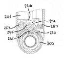
상기 결합 레그 수용 캐비티는 상기 힌지 유닛에 있고, 상기 결합 레그는, 상기 결합 레그가 상기 결합 레그 수용 캐비티에 수용 가능하도록, 상기 카트리지 유닛으로부터 연장될 수 있다.
The engaging leg receiving cavity is in the hinge unit, and the engaging leg can extend from the cartridge unit such that the engaging leg is receivable in the engaging leg receiving cavity.
상기 카트리지 유닛은 제 1 하우징부 및 제 2 하우징부를 포함할 수 있다. 상기 제 1 하우징부는, 상기 힌지 유닛이 상기 카트리지 유닛에 부착될 때, 폐쇄 상태와 개방 상태 사이에서 상기 제 2 하우징부에 대하여 이동하도록 구성될 수 있으며, 상기 결합 레그는 상기 제 1 하우징부로부터 연장될 수 있다.
The cartridge unit may include a first housing part and a second housing part. The first housing part may be configured to move with respect to the second housing part between a closed state and an open state when the hinge unit is attached to the cartridge unit and the engagement leg extends from the first housing part .
상기 힌지 유닛은 서로에 대하여 이동 가능한 제 1 힌지 요소 및 제 2 힌지 요소를 포함할 수 있다. 상기 제 1 하우징부는 상기 제 1 힌지 요소에 부착 가능할 수 있고, 상기 제 2 하우징부는 상기 제 2 힌지 요소에 부착 가능할 수 있다.
The hinge unit may include a first hinge element and a second hinge element movable relative to each other. The first housing part may be attachable to the first hinge element and the second housing part may be attachable to the second hinge element.
상기 결합 요소는, 상기 카트리지 유닛이 폐쇄 상태와 개방 상태 사이에서 이동할 때, 상기 결합 레그 수용 리세스 내로 슬라이딩하도록 구성될 수 있다.
The engaging element may be configured to slide into the engaging leg receiving recess when the cartridge unit is moved between a closed state and an open state.
상기 힌지 유닛은 중심축을 더 포함할 수 있다. 상기 제 1 힌지 요소는 상기 중심축 둘레로 회전 가능할 수 있다.
The hinge unit may further include a central axis. The first hinge element may be rotatable about the central axis.
상기 결합 요소는 상기 중심축에 의해 형성될 수 있다.
The coupling element may be formed by the central axis.
상기 결합 요소는, 상기 제 1 힌지 요소가 상기 중심축 둘레로 회전할 때, 상기 결합 레그 수용 캐비티에 형성된 홈을 따라 슬라이딩해서 상기 결합 레그 수용 캐비티에서 돌출하도록 구성되는, 상기 중심축으로부터 연장되는 레일일 수 있다.
Wherein the engaging element is configured to slide along a groove formed in the engaging leg receiving cavity and protrude from the engaging leg receiving cavity when the first hinge element rotates about the central axis, Lt; / RTI >
본 발명의 다른 양태에 따르면, 물품들을 수용 가능한 카트리지 유닛을 포함하는 끽연 물품용 패키지로서, 상기 카트리지 유닛은, 상기 카트리지 유닛에 수용된 물품들에 접근할 수 있도록 폐쇄 상태와 개방 상태 사이에서 이동 가능하고, 상기 카트리지 유닛은, 상기 카트리지 유닛이 상기 폐쇄 상태와 상기 개방 상태 사이에서 이동하는 것을 방지하도록 구성된 잠금 수단을 더 포함하고, 상기 패키지는, 하우징에 부착 가능한 키를 더 포함하고, 상기 키가 상기 하우징에 부착될 때, 상기 키는 상기 잠금 수단에 작용해서, 상기 카트리지 유닛이 상기 폐쇄 상태와 상기 개방 상태 사이에서 이동하는 것을 허용하도록 구성되는 패키지가 제공된다.
According to another aspect of the present invention there is provided a package for a smoking article comprising a cartridge unit capable of receiving articles, the cartridge unit being movable between a closed state and an open state to allow access to articles contained in the cartridge unit Wherein the cartridge unit further comprises locking means configured to prevent the cartridge unit from moving between the closed state and the open state, wherein the package further comprises a key attachable to the housing, When attached to the housing, the key is configured to act on the locking means to allow the cartridge unit to move between the closed and open states.
상기 키는, 상기 카트리지 유닛이 그 개방 상태에 있을 때 상기 카트리지 유닛에 수용된 물품들에 접근할 수 있게, 힌지 유닛이 상기 카트리지 유닛에 부착될 때 상기 카트리지 유닛을 폐쇄 상태와 개방 상태 사이에서 이동시킬 수 있게 하도록 구성된 힌지 유닛일 수 있다.
Wherein the key moves the cartridge unit between a closed state and an open state when the hinge unit is attached to the cartridge unit such that the cartridge unit is accessible to the items contained in the cartridge unit when the cartridge unit is in its open state The hinge unit may be a hinge unit that is configured to be able to
상기 힌지 유닛은, 상기 힌지 유닛이 상기 카트리지 유닛에 부착될 때, 상기 잠금 수단에 작용해서, 상기 카트리지 유닛이 상기 폐쇄 상태와 상기 개방 상태 사이에서 이동할 수 있게 상기 잠금 수단을 해제하도록 구성될 수 있다.
The hinge unit may be configured to act on the locking means when the hinge unit is attached to the cartridge unit to release the locking means such that the cartridge unit is movable between the closed state and the open state .
상기 잠금 수단은, 상기 힌지 유닛이 상기 카트리지 유닛으로부터 분리될 때, 잠금 면에 놓이도록 구성된 잠금 부재를 포함할 수 있다. 상기 키는, 상기 힌지 유닛이 상기 카트리지 유닛에 부착될 때, 상기 잠금 부재에 작용하여, 상기 잠금 부재를 상기 잠금 면으로부터 멀리 이동시켜서 상기 잠금 수단을 해제하도록 구성될 수 있다.
The locking means may include a locking member configured to rest on the locking surface when the hinge unit is detached from the cartridge unit. The key may be configured to act on the locking member when the hinge unit is attached to the cartridge unit to move the locking member away from the locking surface to release the locking means.
상기 카트리지 유닛은 상기 카트리지 유닛에 수용된 하나 또는 그 초과의 물품을 보유하도록 구성되는 물품 홀더 및 상기 폐쇄 상태와 상기 개방 상태 사이에서 상기 물품 홀더에 대하여 이동하도록 구성되는 하우징부를 더 포함할 수 있다.
The cartridge unit may further include an article holder configured to hold one or more articles received in the cartridge unit, and a housing portion configured to move with respect to the article holder between the closed state and the open state.
상기 잠금 면은 상기 물품 홀더 또는 하우징부 중 하나에 형성될 수 있고, 상기 잠금 부재는, 상기 힌지 유닛이 상기 카트리지 유닛으로부터 분리될 때, 상기 잠금 면에 놓이도록 상응하는 물품 홀더 또는 하우징부로부터 연장될 수 있다.
The locking surface may be formed in one of the article holder or the housing portion and the locking member may extend from a corresponding article holder or housing portion to be placed on the locking surface when the hinge unit is detached from the cartridge unit .
상기 잠금 부재는 상기 잠금 면 쪽으로 편향될 수 있다.
The locking member may be biased toward the locking surface.
상기 패키지는, 상기 힌지 유닛을 상기 카트리지 유닛에 부착하기 위해 상응하는 카트리지 유닛 또는 힌지 유닛 내의 부착 레그 수용 캐비티에 수용 가능한, 상기 물품 홀더 또는 하우징부로부터 연장되는 부착 레그를 더 포함할 수 있다. 상기 잠금 부재는 상기 부착 레그로부터 연장된다.
The package may further comprise an attachment leg extending from the article holder or housing portion, the attachment leg being receivable in an attachment leg receiving cavity in the corresponding cartridge unit or hinge unit for attaching the hinge unit to the cartridge unit. The locking member extends from the attachment leg.
상기 힌지 유닛은 부착 레그 수용 캐비티를 구비할 수 있고, 상기 잠금 부재는, 상기 힌지 유닛이 상기 카트리지 유닛에 부착될 때, 상기 잠금 부재가 가압되어 상기 잠금 면으로부터 멀리 이동하도록 상기 레그 수용 캐비티에 인접하도록 구성될 수 있다.
The hinge unit may include an attachment leg accommodation cavity, the lock member being adjacent to the leg accommodation cavity such that when the hinge unit is attached to the cartridge unit, the locking member is pressed to move away from the locking surface .
상기 잠금 부재는 상기 부착 레그 수용 캐비티 내의 상기 부착 레그의 삽입 방향에 대하여 비스듬한 각도로 연장될 수 있다.
The locking member may extend at an oblique angle with respect to the insertion direction of the attachment leg in the attachment leg accommodation cavity.
상기 하우징부는 제 1 하우징부일 수 있으며, 상기 카트리지는, 상기 카트리지 유닛이 폐쇄 상태와 개방 상태 사이에서 이동할 때, 상기 제 1 하우징부에 대하여 이동하도록 구성된 제 2 하우징부, 및 상기 잠금 수단에 대한 상기 카트리지 유닛의 말단부에 래치(latch)를 더 포함할 수 있다. 상기 래치는, 상기 카트리지 유닛이 상기 폐쇄 상태에 있을 때, 상기 카트리지 유닛의 말단부에서 상기 제 1 및 제 2 하우징부를 서로 접촉 상태로 유지하도록 구성될 수 있다.
The housing portion may be a first housing portion and the cartridge includes a second housing portion configured to move relative to the first housing portion when the cartridge unit is moved between a closed and open state, The cartridge unit may further include a latch at a distal end thereof. The latch may be configured to maintain the first and second housing portions in contact with each other at a distal end of the cartridge unit when the cartridge unit is in the closed state.
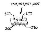
본 발명의 다른 양태에 따르면, 하나 또는 그 초과의 끽연 물품의 단부를 보유하도록 구성된 서브-홀더 및 베이스 마운트를 포함하는 끽연 물품용 패키지의 끽연 물품 홀더가 제공되고, 상기 서브-홀더는 상기 베이스 마운트에 장착 가능하다.
According to another aspect of the present invention there is provided a smoking article holder for a package for smoking articles comprising a sub-holder and a base mount configured to hold one or more ends of a smoking article, the sub- Respectively.
상기 서브-홀더는 상기 하나 또는 그 초과의 끽연 물품의 단부를 에워싸도록 합쳐지는 제 1 및 제 2 유지부(holding part)를 포함할 수 있다.
The sub-holder may include first and second holding parts joined together to surround the end of the one or more smoking articles.
상기 제 1 및 제 2 유지부는, 상기 제 2 유지부가 상기 하나 또는 그 초과의 끽연 물품의 단부를 에워싸기 위해 회전 가능하도록, 일단부에서 서로 힌지식으로 장착될 수 있다.
The first and second holding portions may be hinged to each other at one end so that the second holding portion is rotatable so as to surround the end portion of the one or more smoking articles.
상기 제 1 유지부의 적어도 일단부는, 상기 제 1 및 제 2 유지부가 서로에 대하여 제 위치에 보유되도록, 상기 제 2 유지부에 부착 가능할 수 있다.
At least one end of the first holding portion may be attachable to the second holding portion such that the first and second holding portions are held in position with respect to each other.
상기 서브-홀더는 제 1 서브-홀더일 수 있으며, 상기 홀더는 적어도 제 2 서브-홀더를 더 포함할 수 있다. 상기 제 2 서브-홀더는 상기 베이스 마운트에 장착 가능할 수 있다.
The sub-holder may be a first sub-holder, and the holder may further include at least a second sub-holder. The second sub-holder may be mountable to the base mount.
상기 제 2 서브-홀더는, 상기 제 2 서브-홀더가 상기 제 1 서브-홀더에 대하여 이동할 때, 상기 제 2 서브-홀더에 의해 보유된 하나 또는 그 초과의 물품이 상기 제 1 서브-홀더에 의해 보유된 하나 또는 그 초과의 물품으로부터 멀리 벌어지도록, 상기 제 1 서브-홀더에 대하여 이동하도록 구성될 수 있다.
The second sub-holder is configured such that when the second sub-holder moves relative to the first sub-holder, one or more articles held by the second sub- And move away from the one or more articles held by the first sub-holder.
상기 베이스 마운트는 제 1 베이스부 및 제 2 베이스부를 포함할 수 있다. 상기 제 2 베이스부는 상기 제 1 베이스부에 대하여 선회하도록 구성될 수 있다. 상기 제 1 베이스부는 그 위에 상기 제 1 서브-홀더를 장착하도록 구성될 수 있고, 상기 제 2 베이스부는 그 위에 상기 제 2 서브-홀더를 장착하도록 구성될 수 있다.
The base mount may include a first base portion and a second base portion. The second base portion may be configured to pivot relative to the first base portion. The first base portion may be configured to mount the first sub-holder thereon, and the second base portion may be configured to mount the second sub-holder thereon.
상기 제 2 베이스부는 핀 힌지(pin hinge) 또는 라이브 힌지(live hinge)에 의해 상기 제 1 베이스부에 선회 가능하게 장착될 수 있다.
The second base portion may be pivotally mounted on the first base portion by a pin hinge or a live hinge.
본 발명의 다른 양태에 따르면, 청구항 64 내지 청구항 71 중 어느 한 항에 따른 끽연 물품 홀더를 포함하는 끽연 물품용 패키지가 제공된다.
According to another aspect of the present invention, there is provided a package for a smoking article comprising the smoking article holder according to any one of
본 발명의 다른 양태에 따르면, 제 1 하우징부, 제 2 하우징부, 및 물품들을 유지하기 위한 물품 홀더를 포함하는 카트리지 유닛을 구비한 끽연 물품용 패키지가 제공되고, 상기 제 1 하우징부는, 상기 카트리지 유닛이 그 개방 상태에 있을 때, 상기 카트리지 유닛에 수용된 물품들에 접근할 수 있도록 상기 제 2 하우징부에 대하여 폐쇄 상태와 개방 상태 사이에서 이동하도록 구성되고, 상기 물품 홀더는 하나 또는 그 초과의 물품의 일단부를 보유하도록 구성된 제 1 부분 및 하나 또는 그 초과의 물품의 일단부를 보유하도록 구성된 제 2 부분을 포함하고, 상기 제 2 부분은, 상기 제 1 하우징부가 상기 제 2 하우징부에 대하여 이동될 때, 상기 제 2 부분에 의해 보유된 하나 또는 그 초과의 물품이 상기 제 1 부분에 의해 보유된 하나 또는 그 초과의 물품으로부터 멀리 벌어지도록 상기 제 1 부분에 대하여 이동 가능하다.
According to another aspect of the present invention, there is provided a package for a smoking article having a cartridge unit including a first housing part, a second housing part, and an article holder for holding the articles, wherein the first housing part comprises: When the unit is in its open state, is configured to move between a closed state and an open state with respect to the second housing portion to allow access to the items contained in the cartridge unit, the article holder comprising one or more articles And a second portion configured to hold one end of one or more articles, wherein the second portion is configured to hold one end of one or more articles when the first housing portion is moved relative to the second housing portion , One or more of the articles held by the second part may be replaced by one or more articles held by the first part Emitter can happen so far moved relative to the first portion.
상기 제 1 하우징부는 상기 물품 홀더에 대하여 이동하도록 구성될 수 있다.
The first housing part may be configured to move relative to the article holder.
상기 제 1 하우징부는, 상기 제 1 하우징부가 상기 물품 홀더에 대하여 이동될 때, 상기 물품 홀더의 상기 제 2 부분에 작용해서 상기 제 2 부분을 가압하여 상기 제 1 부분에 대하여 이동시키도록 구성된 안내 요소를 포함할 수 있다.
Wherein the first housing portion comprises a guide element configured to act on the second portion of the article holder to urge the second portion against the first portion when the first housing portion is moved relative to the article holder, . ≪ / RTI >
상기 안내 요소는 상기 제 2 부분에 인접해서 상기 제 2 부분을 가압하여 상기 제 1 부분에 대하여 이동시키도록 구성된 안내면일 수 있다.
The guiding element may be a guiding surface configured to press against and move relative to the first portion adjacent the second portion.
상기 물품 홀더는 상기 물품 홀더의 상기 제 2 부분을 가압하여 상기 제 1 부분에 대하여 선회시키도록 구성된 안내 요소를 더 포함할 수 있다.
The article holder may further comprise a guiding element configured to press the second portion of the article holder to pivot relative to the first portion.
상기 안내 요소는 자석일 수 있다.
The guiding element may be a magnet.
상기 제 2 부분은 핀 힌지 또는 라이브 힌지에 의해 상기 제 1 부분에 선회 가능하게 장착될 수 있다.
The second portion may be pivotally mounted to the first portion by a pin hinge or a live hinge.
상기 제 2 하우징부는 상기 물품 홀더에 대하여 이동하도록 구성될 수 있다.
The second housing part may be configured to move relative to the article holder.
상기 물품 홀더는 하나 또는 그 초과의 물품의 일단부를 보유하도록 구성된 제 3 부분을 더 포함할 수 있다. 상기 제 3 부분은, 상기 제 2 하우징부가 상기 물품 홀더에 대하여 이동될 때, 상기 제 3 부분에 의해 보유된 하나 또는 그 초과의 물품이 상기 제 1 부분에 의해 보유된 하나 또는 그 초과의 물품으로부터 멀리 벌어지도록 상기 제 1 부분에 대하여 이동 가능할 수 있다.
The article holder may further comprise a third part configured to hold one end of one or more articles. Wherein the third portion comprises one or more articles held by the third portion when the second housing portion is moved relative to the article holder from one or more articles held by the first portion And may be movable with respect to the first portion to spread apart.
상기 제 2 하우징부는, 상기 제 2 하우징부가 상기 물품 홀더에 대하여 이동될 때, 상기 물품 홀더의 상기 제 3 부분에 작용해서 상기 제 3 부분을 가압하여 상기 제 1 부분에 대하여 선회시키도록 구성된 안내 요소를 포함할 수 있다.
Wherein the second housing portion is configured to guide the third portion of the article holder when the second housing portion is moved relative to the article holder and to pivot the third portion against the first portion, . ≪ / RTI >
상기 안내 요소는 상기 제 3 부분에 인접해서 상기 제 3 부분을 가압하여 상기 제 1 부분에 대하여 선회시키도록 구성된 안내면일 수 있다.
The guiding element may be a guiding surface adapted to press the third portion adjacent the third portion to pivot relative to the first portion.
상기 안내면은 레지(ledge)에 의해 형성될 수 있다.
The guide surface may be formed by a ledge.
상기 물품 홀더는 베이스 마운트를 포함할 수 있다. 상기 제 1 부분은 상기 베이스 마운트의 제 1 베이스부 및 하나 또는 그 초과의 물품의 일단부를 보유하도록 구성된 제 1 서브-홀더를 포함할 수 있고, 상기 제 2 부분은 상기 베이스 마운트의 제 2 베이스부 및 하나 또는 그 초과의 물품의 일단부를 보유하도록 구성된 제 2 서브-홀더를 포함할 수 있다.
The article holder may include a base mount. The first portion may include a first sub-holder configured to hold a first base portion of the base mount and one end of one or more articles, and the second portion may include a second base portion And a second sub-holder configured to hold one end of one or more articles.
상기 물품 홀더는 상기 제 2 부분을 가압하여 상기 제 1 부분에 대하여 선회시키도록 구성되는 탄성 부재를 더 포함할 수 있다.
The article holder may further include an elastic member configured to press and rotate the second portion relative to the first portion.
본 발명의 다른 양태에 따르면, 물품들을 수용 가능한 카트리지 유닛에 장착하기 위한 힌지 유닛이 제공되고, 상기 힌지 유닛은, 상기 카트리지 유닛이 그 개방 상태에 있을 때 상기 카트리지 유닛에 수용된 물품들에 접근할 수 있도록, 상기 힌지 유닛이 상기 카트리지 유닛에 부착될 때 상기 카트리지 유닛을 폐쇄 상태와 개방 상태 사이에서 이동시킬 수 있게 카트리지 유닛에 부착하도록 구성된다.
According to another aspect of the present invention, there is provided a hinge unit for mounting articles to an acceptable cartridge unit, the hinge unit being capable of accessing the items contained in the cartridge unit when the cartridge unit is in its open state So as to move the cartridge unit between a closed state and an open state when the hinge unit is attached to the cartridge unit.
상기 힌지 유닛은 상기 카트리지 유닛에 부착하도록 구성된 제 1 및 제 2 힌지 요소를 포함할 수 있고, 상기 제 1 힌지 요소는, 상기 카트리지 유닛을 폐쇄 상태와 개방 상태 사이에서 이동시킬 수 있게 하도록, 상기 제 1 및 제 2 힌지 요소의 중심 축선을 중심으로 상기 제 2 힌지 요소에 대하여 회전 가능할 수 있다.
The hinge unit may include first and second hinge elements configured to attach to the cartridge unit, wherein the first hinge element is configured to move the cartridge unit between a closed state and an open state, 1 and the second hinge element about the central axis of the second hinge element.
상기 제 1 힌지 요소는 상기 힌지 유닛을 상기 카트리지 유닛에 해제 가능하게 부착하도록 구성된 부착 수단을 포함할 수 있다.
The first hinge element may include attachment means configured to releasably attach the hinge unit to the cartridge unit.
상기 제 2 힌지 요소는, 상기 카트리지 유닛이 그 개방 상태에 있을 때, 상기 힌지 유닛이 상기 카트리지 유닛으로부터 분리되는 것을 방지하기 위해, 상기 카트리지 유닛을 상기 힌지 유닛과 결합하도록 구성된 결합 수단을 포함할 수 있다.
The second hinge element may comprise engaging means configured to engage the cartridge unit with the hinge unit to prevent the hinge unit from being detached from the cartridge unit when the cartridge unit is in its open state have.
상기 힌지는 원통형일 수 있다.
The hinge may be cylindrical.
상기 힌지의 직경은 폐쇄 상태에서 카트리지 유닛의 깊이와 동일해지도록 구성될 수 있다.
The diameter of the hinge can be configured to be equal to the depth of the cartridge unit in the closed state.
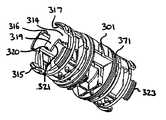
상기 힌지 유닛은 카트리지 유닛의 제 1 하우징부에 부착하도록 구성된 제 1 힌지 요소 및 카트리지 유닛의 제 2 하우징부에 부착하도록 구성된 제 2 힌지 요소를 포함할 수 있고, 카트리지 유닛이 힌지 유닛에 장착될 때, 상기 카트리지 유닛의 제 1 하우징부가 상기 카트리지 유닛의 제 2 하우징부에 대하여 이동 가능하도록, 상기 제 1 힌지 요소는 상기 제 1 및 제 2 힌지 요소의 중심 축선을 중심으로 상기 제 2 힌지 요소에 대하여 회전 가능할 수 있다.
The hinge unit may include a first hinge element configured to attach to the first housing portion of the cartridge unit and a second hinge element configured to attach to the second housing portion of the cartridge unit, and when the cartridge unit is mounted to the hinge unit Wherein the first hinge element is movable relative to the second hinge element about a central axis of the first and second hinge elements such that the first housing portion of the cartridge unit is movable relative to the second housing portion of the cartridge unit It may be rotatable.
본 발명의 다른 양태에 따르면, 끽연 물품들을 수용하기 위한 카트리지 유닛으로서, 힌지 유닛에 부착 가능하며, 상기 카트리지 유닛이 그 개방 상태에 있을 때, 상기 카트리지 유닛에 수용된 물품들에 접근할 수 있도록, 상기 힌지 유닛이 상기 카트리지 유닛에 부착될 때 폐쇄 상태와 개방 상태 사이에서 이동하도록 구성되는 카트리지 유닛이 제공된다.
According to another aspect of the present invention, there is provided a cartridge unit for accommodating smoking articles, the cartridge unit comprising: a hinge unit attachable to the hinge unit, wherein when the cartridge unit is in its open state, There is provided a cartridge unit configured to move between a closed state and an open state when the hinge unit is attached to the cartridge unit.
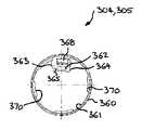
상기 카트리지 유닛은 힌지 유닛에 부착되도록 구성되는 제 1 하우징부 및 제 2 하우징부를 더 포함할 수 있고, 상기 제 1 하우징부는, 상기 카트리지 유닛이 힌지 유닛에 부착될 때, 상기 카트리지 유닛이 그 폐쇄 상태와 개방 상태 사이에서 이동하도록 상기 제 2 하우징부에 대하여 힌지 유닛을 중심으로 회전하도록 구성된다.
The cartridge unit may further include a first housing part and a second housing part configured to be attached to the hinge unit, and the first housing part is configured such that when the cartridge unit is attached to the hinge unit, And to rotate about the hinge unit with respect to the second housing part to move between the open position and the open position.
상기 카트리지 유닛은 상기 힌지 유닛이 상기 카트리지 유닛으로부터 분리될 때 상기 카트리지 유닛이 상기 폐쇄 상태와 상기 개방 상태 사이에서 이동하는 것을 방지하도록 구성된 잠금 수단을 더 포함할 수 있다.
The cartridge unit may further include locking means configured to prevent the cartridge unit from moving between the closed state and the open state when the hinge unit is separated from the cartridge unit.
상기 카트리지 유닛은 상기 카트리지 유닛에 수용된 하나 또는 그 초과의 물품을 보유하도록 구성된 물품 홀더를 더 포함할 수 있다.
The cartridge unit may further include an article holder configured to hold one or more articles contained in the cartridge unit.
상기 물품 홀더는 하나 또는 그 초과의 물품의 일단부를 보유하도록 구성된 제 1 부분 및 하나 또는 그 초과의 물품의 일단부를 보유하도록 구성된 제 2 부분을 포함할 수 있고, 상기 제 2 부분은, 상기 카트리지 유닛이 폐쇄 상태와 개방 상태 사이에서 이동될 때, 상기 제 2 부분에 의해 보유된 하나 또는 그 초과의 물품이 상기 제 1 부분에 의해 보유된 하나 또는 그 초과의 물품으로부터 멀리 벌어지도록 상기 제 1 부분에 대하여 이동 가능할 수 있다.
The article holder may comprise a first part configured to hold one end of one or more articles and a second part configured to hold one end of one or more articles, Is moved between the closed state and the open state such that one or more articles held by the second section extend away from one or more articles held by the first section, Lt; / RTI >
상기 카트리지 유닛은 상기 힌지 유닛을 상기 카트리지 유닛에 해제 가능하게 부착하도록 구성된 부착 수단을 더 포함할 수 있다.
The cartridge unit may further include attachment means configured to releasably attach the hinge unit to the cartridge unit.
상기 카트리지 유닛은, 상기 카트리지 유닛이 그 개방 상태에 있을 때, 상기 힌지 유닛이 상기 카트리지 유닛으로부터 분리되는 것을 방지하기 위해, 상기 카트리지 유닛을 상기 힌지 유닛과 결합하도록 구성된 결합 수단을 더 포함할 수 있다.
The cartridge unit may further comprise engaging means configured to engage the cartridge unit with the hinge unit to prevent the hinge unit from being detached from the cartridge unit when the cartridge unit is in its open state .
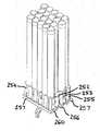
본 발명의 다른 양태에 따르면, 홀더로부터 직립하는 복수의 카트리지 유닛을 유지하도록 구성된 홀더가 제공된다.
According to another aspect of the present invention, there is provided a holder configured to hold a plurality of cartridge units standing upright from a holder.
상기 홀더는 힌지 유닛을 수용하기 위해 장착 요소를 더 포함할 수 있다.
The holder may further comprise a mounting element for receiving the hinge unit.
상기 힌지 유닛은 그것을 통해 형성된 보어를 포함할 수 있고, 상기 장착 요소는 상기 보어에 수용되는 돌출 로드(rod)일 수 있다.
The hinge unit may include a bore formed therethrough, and the mounting element may be a protruding rod received in the bore.
본 발명의 다른 양태에 따르면, 힌지 유닛, 및 끽연 물품들을 위한 복수의 카트리지 유닛을 포함하는 키트가 제공되고, 상기 복수의 카트리지 유닛 각각은 상기 힌지 유닛에 개별적으로 부착 가능하다.
According to another aspect of the present invention, there is provided a kit including a hinge unit and a plurality of cartridge units for smoking articles, wherein each of the plurality of cartridge units is individually attachable to the hinge unit.
상기 키트는 2개 이상의 카트리지 유닛을 유지하기 위한 홀더를 더 포함할 수 있다.
The kit may further comprise a holder for holding two or more cartridge units.
본 발명의 다른 양태에 따르면, 물품들을 수용 가능한 카트리지 유닛을 구비한 끽연 물품용 패키지를 개방하는 방법이 제공되고, 상기 방법은, 힌지 유닛을 상기 카트리지 유닛에 부착하는 단계, 및 상기 카트리지 유닛이 그 개방 상태에 있을 때 상기 카트리지 유닛에 수용된 물품들에 접근할 수 있도록 상기 카트리지 유닛을 폐쇄 상태와 개방 상태 사이에서 이동시키기 위해 상기 카트리지 유닛의 구역을 상기 힌지 유닛에 대하여 회전시키는 단계를 포함한다.
According to another aspect of the present invention, there is provided a method of opening a package for a smoking article having a cartridge unit capable of receiving articles, the method comprising: attaching a hinge unit to the cartridge unit; And rotating the area of the cartridge unit relative to the hinge unit to move the cartridge unit between the closed and open states to allow access to the items contained in the cartridge unit when in an open state.
본 발명의 다른 양태에 따르면, 끽연 물품용 패키지에 끽연 물품들을 장착하는 방법으로서, 하나 또는 그 초과의 끽연 물품의 단부를 서브-홀더에 장착하는 단계, 및 상기 서브-홀더를 베이스 마운트에 장착해서 끽연 물품 홀더를 형성하는 단계를 포함하는 방법이 제공된다.
According to another aspect of the present invention, there is provided a method of mounting smoking articles in a package for a smoking article comprising the steps of mounting one or more ends of a smoking article to a sub-holder and mounting the sub- A method is provided comprising the step of forming a smoking article holder.
상기 방법은 상기 끽연 물품 홀더 및 하나 또는 그 초과의 끽연 물품을 하우징에 수용하는 단계를 더 포함할 수 있다.
The method may further comprise the step of receiving the smoking article holder and one or more smoking articles in the housing.
상기 서브-홀더는 제 1 및 제 2 유지부를 포함할 수 있고, 상기 방법은 하나 또는 그 초과의 끽연 물품의 단부를 상기 제 1 유지부에 대하여 위치시키는 단계 및 상기 하나 또는 그 초과의 끽연 물품의 단부를 상기 제 2 유지부로 에워싸는 단계를 더 포함할 수 있다.
The sub-holder may include first and second holding portions, the method comprising the steps of positioning one or more ends of the smoking article with respect to the first holding portion and positioning the one or more smoking articles And enclosing the end portion with the second retaining portion.
본 발명의 다른 양태에 따르면, 제 1 하우징부 및 제 2 하우징부를 구비하는, 물품들을 수용 가능한 카트리지 유닛, 및 상기 카트리지 유닛에 부착 가능한 힌지 유닛을 포함하는 끽연 물품용 패키지가 제공되고, 상기 제 1 하우징부는, 상기 카트리지에 수용된 물품들에 접근할 수 있도록 상기 힌지 유닛이 상기 카트리지 유닛에 부착될 때 폐쇄 상태와 개방 상태 사이에서 상기 제 2 하우징부에 대하여 상기 힌지 유닛을 중심으로 힌지결합하도록 구성된다.
According to another aspect of the present invention, there is provided a package for a smoking article comprising a cartridge unit capable of accommodating items, and a hinge unit attachable to the cartridge unit, the first housing portion and the second housing portion, The housing portion is configured to hinge about the hinge unit with respect to the second housing portion between a closed state and an open state when the hinge unit is attached to the cartridge unit to allow access to articles contained in the cartridge .
이제, 하기의 첨부도면들을 참조로, 본 발명의 실시예들을 예로서만 기술한다.
Reference will now be made, by way of example only, to the embodiments of the invention, examples of which are illustrated in the accompanying drawings.
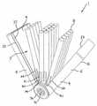
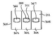
도 1은 본 발명의 실시예에 따른 카트리지 유닛 및 힌지 유닛을 구비한 폐쇄 위치로 도시된 끽연 물품용 패키지의 사시도이고;
도 2는 카트리지 유닛에 끽연 물품들이 수용되어 있는 도 1에 도시된 끽연 물품용 패키지의 개방 위치에서의 사시도이고;
도 3은 카트리지 유닛으로부터 끽연 물품들이 제거되어 있는 도 1에 도시된 끽연 물품용 패키지의 개방 위치에서의 사시도이고;
도 4는 카트리지 유닛으로부터 힌지 유닛이 제거되어 있는 도 1에 도시된 끽연 물품용 패키지의 사시도이고;
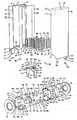
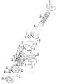
도 5는 도 1에 도시된 끽연 물품용 패키지의 분해도이고;
도 6은 도 1에 도시된 끽연 물품용 패키지의 단면도이고;
도 7은 도 1에 도시된 끽연 물품용 패키지의 다수의 카트리지 유닛용 홀더 및 힌지 유닛의 사시도이고;
도 8은 홀더로부터 힌지 유닛이 제거되어 있는 도 7에 도시된 홀더의 사시도이고;
도 9는 본 발명의 다른 실시예에 따른, 카트리지 유닛에 끽연 물품들이 수용되어 있는, 개방 위치로 도시된 카트리지 유닛 및 힌지 유닛을 구비한 끽연 물품용 패키지의 사시도이고;
도 10은 폐쇄 위치에서의 도 9에 도시된 패키지의 사시도이고;
도 11은 도 9에 도시된 카트리지 유닛의 분해 사시도이고;
도 12는 도 9에 도시된 카트리지 유닛의 아래에서부터 본 사시도이고;
도 13은 도 12에 도시된 사시도의 확대도이고;
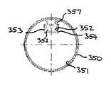
도 14는 도 9에 도시된 카트리지 유닛의 아래에서부터 본 평면도이고;
도 15는 도 9에 도시된 카트리지 유닛의 분해 측면도이고;
도 16은 내부에 끽연 물품들이 수용되어 있는 카트리지 유닛의 끽연 물품 홀더의 측면도이고;
도 17은 내부에 끽연 물품들이 수용되어 있는 도 16에 도시된 카트리지 유닛의 끽연 물품 홀더의 사시도이고;
도 18은 도 17에 도시된 카트리지 유닛의 서브-홀더의 사시도이고;
도 19는 도 18에 도시된 끽연 물품 홀더의 서브-홀더의 미조립(unassembled) 사시도이고;
도 20은 외부 링들이 폐쇄 위치에 있는 도 9에 도시된 힌지 유닛의 평면도이고;
도 21은 외부 링들이 폐쇄 위치에 있는 도 20에 도시된 힌지 유닛의 사시도이고;
도 22는 외부 링들이 개방 위치에 있는 도 20에 도시된 힌지 유닛의 평면도이고;
도 23은 외부 링들이 개방 위치에 있는 도 20에 도시된 힌지 유닛의 사시도이고;
도 24는 도 20에 도시된 힌지 유닛의 분해 사시도이고;
도 25는 도 20에 도시된 힌지 유닛의 다른 분해 사시도이고;
도 26은 도 20에 도시된 힌지 유닛의 다른 분해 사시도이고;
도 27은 도 20에 도시된 힌지 유닛의 외부 링의 사시도이고;
도 28은 도 27에 도시된 외부 링의 측면도이고;
도 29는 도 20에 도시된 힌지 유닛의 내부 링의 사시도이고;
도 30은 도 29에 도시된 내부 링의 측면도이고;
도 31은 도 20에 도시된 힌지 유닛의 중심축의 위에서부터 본 사시도이고;
도 32는 도 31에 도시된 중심축의 위에서부터 본 평면도이고;
도 33은 도 31에 도시된 중심축의 아래에서부터 본 평면도이고;
도 34는 패키지가 폐쇄 위치에 있고 서브-홀더들이 생략되어 있는, 힌지 유닛의 외부 링들 중 하나를 통한 도 9에 도시된 패키지의 부분 단면 측면도이고;
도 35는 패키지가 개방 위치에 있고 서브-홀더들이 생략되어 있는, 힌지 유닛의 외부 링들 중 하나를 통한 도 9에 도시된 패키지의 부분 단면 측면도이고;
도 36은 패키지가 폐쇄 위치에 있는, 힌지 유닛의 내부 링을 통한 도 20에 도시된 힌지 유닛의 부분 단면 측면도이고;
도 37은 패키지가 폐쇄 위치에 있는, 힌지 유닛의 내부 링을 통한 도 9에 도시된 패키지의 부분 단면 측면도이다.1 is a perspective view of a package for a smoking article shown in a closed position with a cartridge unit and a hinge unit according to an embodiment of the present invention;
Fig. 2 is a perspective view of the package for smoking article in the open position shown in Fig. 1 in which smoking articles are housed in the cartridge unit; Fig.
3 is a perspective view in an open position of the package for a smoking article shown in Fig. 1 in which smoking articles are removed from the cartridge unit;
4 is a perspective view of the package for smoking article shown in Fig. 1 with the hinge unit removed from the cartridge unit; Fig.
5 is an exploded view of the package for a smoking article shown in Fig. 1;
6 is a cross-sectional view of the package for a smoking article shown in Fig. 1;
7 is a perspective view of a holder and a hinge unit for a plurality of cartridge units of the package for a smoking article shown in Fig. 1;
Figure 8 is a perspective view of the holder shown in Figure 7 with the hinge unit removed from the holder;
9 is a perspective view of a package for a smoking article having a cartridge unit and a hinge unit, shown in an open position, in which smoking articles are received in a cartridge unit, according to another embodiment of the present invention;
Figure 10 is a perspective view of the package shown in Figure 9 in the closed position;
11 is an exploded perspective view of the cartridge unit shown in Fig. 9; Fig.
Figure 12 is a perspective view from below of the cartridge unit shown in Figure 9;
13 is an enlarged view of the perspective view shown in Fig. 12;
14 is a plan view from below of the cartridge unit shown in Fig. 9;
Figure 15 is an exploded side view of the cartridge unit shown in Figure 9;
16 is a side view of the smoking article holder of the cartridge unit in which the smoking articles are housed;
Fig. 17 is a perspective view of the smoking article holder of the cartridge unit shown in Fig. 16 in which smoking articles are housed therein; Fig.
Figure 18 is a perspective view of the sub-holder of the cartridge unit shown in Figure 17;
Fig. 19 is an unassembled perspective view of the sub-holder of the smoking article holder shown in Fig. 18; Fig.
Figure 20 is a plan view of the hinge unit shown in Figure 9 with the outer rings in the closed position;
Figure 21 is a perspective view of the hinge unit shown in Figure 20 with the outer rings in the closed position;
Figure 22 is a plan view of the hinge unit shown in Figure 20 with the outer rings in the open position;
Figure 23 is a perspective view of the hinge unit shown in Figure 20 with the outer rings in the open position;
FIG. 24 is an exploded perspective view of the hinge unit shown in FIG. 20; FIG.
25 is another exploded perspective view of the hinge unit shown in Fig. 20;
26 is another exploded perspective view of the hinge unit shown in Fig. 20;
Figure 27 is a perspective view of the outer ring of the hinge unit shown in Figure 20;
28 is a side view of the outer ring shown in Fig. 27;
29 is a perspective view of the inner ring of the hinge unit shown in Fig. 20;
Figure 30 is a side view of the inner ring shown in Figure 29;
31 is a perspective view from above the central axis of the hinge unit shown in Fig. 20;
32 is a plan view as seen from above the center axis shown in Fig. 31;
Fig. 33 is a plan view as viewed from below the center axis shown in Fig. 31; Fig.
Figure 34 is a partial cross-sectional side view of the package shown in Figure 9 through one of the outer rings of the hinge unit, with the package in the closed position and the sub-holders omitted;
35 is a partial cross-sectional side view of the package shown in FIG. 9 through one of the outer rings of the hinge unit, with the package in the open position and the sub-holders omitted;
Figure 36 is a partial cross-sectional side view of the hinge unit shown in Figure 20 through the inner ring of the hinge unit with the package in the closed position;
Figure 37 is a partial cross-sectional side view of the package shown in Figure 9 through the inner ring of the hinge unit, with the package in the closed position.
도 1 내지 도 4를 참조하면, 카트리지 유닛(2) 및 힌지 유닛(3)을 포함하는 끽연 물품용 패키지(1)가 도시된다. 힌지 유닛(3)은 원통형이다.
Referring to Figs. 1 to 4, there is shown a
여기서 사용되는 용어인, "끽연 물품(smoking article)"은, 이들에 제한되는 것은 아니지만, 담배(tobacco), 담배 파생품(tobacco derivatives), 확대된 담배(expanded tobacco), 재생 담배(reconstituted tobacco) 또는 담배 대용품(tobacco substitutes)에 기초하고 있는지의 여부에 따른, 궐련(cigarette), 여송연(cigar) 및 가는 담배(cigarillo)와 같은 끽연 가능한 제품들 및 HnB(heat-not-burn; 가열하되 타지 않는) 제품들을 포함하는 임의의 담배 산업 제품을 포함하는 용어이다. 끽연 물품에는 끽연자에 의해 빨아 들여진 기체 흐름을 위한 필터가 제공될 수 있다.
As used herein, the term "smoking article" includes, but is not limited to, tobacco, tobacco derivatives, expanded tobacco, reconstituted tobacco, Smoking products such as cigarettes, cigars and thin cigars, and heat-not-burn (HnB) (heat-not-burns, depending on whether they are based on tobacco substitutes) ) ≪ / RTI > products. The smoking article may be provided with a filter for gas flow sucked by the smoker.
카트리지 유닛(2)은, 도 4에 도시된 바와 같이, 힌지 유닛(3)에 대하여 제거 가능하게 부착된다. 즉, 카트리지 유닛(2)과 힌지 유닛(3)은 서로 분리될 수 있다. 카트리지 유닛(2)은 대향하는 제 1 및 제 2 하우징부(5, 6)를 구비한 외부 쉘 또는 하우징(4)을 갖는다. 끽연 물품 수용 공간(7)은 끽연 물품(8)들을 내부에 수용하는 하우징(4)에 의해 규정된다. 제 1 및 제 2 하우징부(5, 6)는 끽연 물품 수용 공간(7)에 접근할 수 있게 분리 가능하다.
The
제 1 및 제 2 하우징부(5, 6)는 세장형(elongate)이다. 제 1 및 제 2 하우징부(5, 6) 각각은 일단부에서 힌지 유닛(3)에 장착 가능하다. 즉, 제 1 및 제 2 하우징부(5, 6)는 힌지 유닛(3)에 부착 가능하다. 2개의 하우징부는, 도 1에 도시된 바와 같이, 끽연 물품(8)들이 외부 하우징(4)에 의해 에워싸이도록 하우징부들(5, 6)이 서로에 대항하여 놓이는 폐쇄 위치와, 도 2에 도시된 바와 같이, 끽연 물품 수용 공간(7)에 배치된 끽연 물품(8)들에 접근할 수 있도록 하우징부들(5, 6)이 힌지 유닛(3)을 중심으로 서로로부터 힌지식으로 멀어지는 개방 위치 사이에서, 힌지 유닛(3)을 중심으로 회전 가능하다.
The first and
카트리지 유닛(2)의 제 1 하우징부(5)는 후방 벽(rear wall)(9), 2개의 대향하는 측벽(10) 및 상부 벽(top wall)(11)을 갖는다. 제 1 하우징부(5)의 측벽(10)들은 후방 벽(9)의 대향 에지들로부터 연장되고, 평행하지만 서로 이격되게 연장된다. 상부 벽(11)은 후방 벽(9) 및 측벽(10)의 상단부로부터 연장된다. 도 5를 참조하면, 후방 벽(9)의 하단부로부터 안쪽으로 플랜지가 연장되어, 저부 벽(bottom wall)(13)의 일부를 형성한다. 저부 벽(13)은 아치형 저부 면(14)을 갖는다. 제 1 하우징부(5)의 아치형 저부 면(14)은, 하기에서 분명해지는 바와 같이, 힌지 유닛(3)의 외부 면의 원주에 대응해서, 외부 면의 원주에 대항하여 놓이게 된다.
The
유사하게, 제 2 하우징부(6)는 후방 벽(16), 2개의 대향하는 측벽(17) 및 상부 벽(18)을 갖는다. 제 2 하우징부(6)의 측벽(17)들은 후방 벽(16)의 대향하는 에지들로부터 연장되고, 평행하지만 서로 이격되게 연장된다. 상부 벽(18)은 후방 벽(16) 및 측벽(17)의 상단부로부터 연장된다. 후방 벽(16)의 하단부로부터 플랜지가 안쪽으로 연장된다. 플랜지는 제 2 하우징부(6)의 저부 벽(19)을 형성한다. 저부 벽(19)은 아치형 저부 면(20)을 갖는다.
Similarly, the
패키지(1)가, 도 1에 도시된 바와 같이, 그 폐쇄 위치에 있을 때, 제 1 하우징부 측벽(10) 및 상부 벽(11)의 자유 에지(22)는 제 2 하우징부 측벽(17) 및 상부 벽(18)의 자유 에지(23)에 인접한다. 따라서, 외부 하우징(4)에 의해 규정된 끽연 물품 수용 공간(7)(도 2 참조)은 하우징(4)에 의해 에워싸인다.
1, the
또한, 외부 하우징(4)은 제 1 하우징부(5)의 자유 에지(22)의 내측으로부터 오프셋되어 거기로부터 바깥쪽으로 연장되는 내부 립(lip)(25)을 갖는다. 제 1 및 제 2 하우징부(5, 6)가 팩(pack)의 폐쇄 위치로 합쳐지면, 제 2 하우징부(6)의 자유 에지(23)는 제 1 하우징부(5)의 내부 립(25)에 겹쳐진다(overlap). 내부 립(25)은 카트리지 유닛(2)의 끽연 물품 수용 공간(7)에 오염물이 진입하는 것을 제한한다. 본 실시예에 있어서, 내부 립(25)은 u-형상으로 형성되는 세장형 시트(26)로 형성되고(도 5 참조), 접착제와 같은 공지의 수단에 의해 제 1 하우징부(5)에 견고하게 장착된다. 대안으로서, 내부 립(25)은 제 1 하우징부(5)와 일체로 형성될 수 있다.
The
도 5를 참조하면, 제 1 하우징부(5)는 그 하단부로부터 아래쪽으로 연장되는 2개의 레그(legs)(27, 28)를 갖는다. 레그들 중 하나(27)는 제 1 하우징부(5)의 아치형 저부 면(14)으로부터 연장되고, 다른 레그(28)는 제 1 하우징부(5)의 아치형 저부 벽(13)의 연장부(29)로부터 아래쪽으로 연장된다. 따라서, 2개의 레그(27, 28)는 평행하지만 서로 이격되게 연장되어, 그들 사이에 아치면(arced face)이 규정된다. 보유 요소로서 작용하는 자석(30)은 각각의 레그(27, 28)에 견고하게 장착된다. 각각의 보유 요소는 각각의 레그(27, 28)의 자유 단부에 장착된다. 보유 요소(30)들은 각각의 레그(27, 28)의 단부 내의 상응하는 리세스(31)들에 각각 수용된다.
Referring to Fig. 5, the
제 2 하우징부(6)는 그 하단부로부터 아래쪽으로 연장되는 2개의 레그(33, 34)를 갖는다. 레그들 중 하나(33)는 제 2 하우징부(6)의 아치형 저부 면(20)으로부터 연장되고, 다른 레그(34)는 제 2 하우징부(6)의 아치형 저부 벽(19)의 연장부(도시되지 않음)로부터 아래쪽으로 연장된다. 따라서, 2개의 레그(33, 34)는 평행하지만 서로 이격되게 연장되어, 그들 사이에 아치면이 규정된다. 보유 요소로서 작용하는 자석(36)은 각각의 레그(33, 34)에 견고하게 장착된다. 각각의 보유 요소는 각각의 레그(33, 34)의 자유 단부에 장착된다. 보유 요소(36)들은 각각의 레그(33, 34)의 단부 내의 상응하는 리세스(37)들에 각각 수용된다.
The second housing part (6) has two legs (33, 34) extending downward from its lower end. One of the
각각의 하우징부(5, 6)가 2개의 레그를 갖고 있지만, 대안적인 실시예에 있어서는, 하기에서 분명해지는 바와 같이, 각각의 하우징부가 단일의 레그를 갖는다. 2개의 레그, 예컨대 보유 요소들을 갖는 것으로 기술된 실시예들의 특징들은 각각의 하우징부가 단일의 레그를 갖는 후술하는 실시예들과 함께 사용될 수도 있음이 이해될 것이다.
Each
제 1 하우징부(5)의 2개의 레그(27, 28)는 하나의 측벽(10)에 인접하지만, 그로부터 약간 안쪽으로 배치된다. 제 2 하우징부(6)의 2개의 레그(33, 34)는, 2개의 하우징부가 합쳐질 때, 제 2 하우징부(6)의 대향하는 측벽(17)에 인접하지만, 그로부터 약간 안쪽으로 배치된다. 따라서, 제 1 하우징부(5)의 레그들(27, 28)은 제 2 하우징부(6)의 레그들(33, 34)에 대하여 외부 하우징(4)의 맞은편에 배치된다. 카트리지 유닛(2)이 조립되고 하우징부들이 합쳐질 때, 제 1 하우징부(5)의 레그들(27, 28) 및 제 2 하우징부(6)의 레그들(33, 34)은 카트리지 유닛(2)의 하단부로부터 서로 평행하게 연장된다. 본 실시예에 있어서, 제 1 하우징부(5) 및 제 2 하우징부(6)는, 제 1 하우징부(5)에 견고하게 장착되는 내부 립(26)을 제외하고는, 서로 동일하다. 이 배열체의 장점은 단일의 주형(mold)이 하우징부들 각각을 형성하는데 사용될 수 있다는 점이다.
The two
도 3 내지 도 5를 참조하면, 카트리지 유닛(2)은 끽연 물품 홀더를 더 포함한다. 끽연 물품 홀더는 끽연 물품들을 유지하도록 배열된다. 즉, 끽연 물품 홀더는 복수의 끽연 물품(8)의 단부를 보유하도록 구성된다.
3 to 5, the
끽연 물품 홀더는 베이스 마운트(38)를 갖는다. 베이스 마운트(38)는 중간 베이스부(39) 및 2개의 외부 베이스부(40)를 갖는다. 2개의 외부 베이스부(40)는 중간 베이스부(39)의 대향 측부들에 배치된다. 베이스 마운트(38)는 베이스 지지 플레이트(41) 및 베이스 지지부(42)를 더 갖는다.
The smoking article holder has a base mount (38). The
베이스 지지부(42)는 상부 면(44) 및 하부 면을 구비한 본체(43)를 갖는다. 하부 면은 아치형이다. 상부 면(44)은 본체 상부 면(44)의 중심 구역에서 직립하는 직사각형 플랫폼(46) 상에 2개의 장착 스터드(45)를 갖는다. 장착 스터드(45)들은 중간 베이스부(39)를 베이스 지지부(42)에 견고하게 장착하도록 배치된다. 상부 면(44)은 2개의 외부 부분(47)을 더 포함한다. 2개의 외부 부분(47) 각각은 내부에 견고하게 장착된, 안내 요소로서 작용하는 자석(48)을 갖는다. 상부 면(44)의 2개의 외부 부분(47)은 직사각형 플랫폼(46)에 대하여 비스듬한 각도로 연장된다. 부착 레그로서 작용하는 2개의 베이스 레그(50, 51)는 베이스 지지 본체(43)의 아치형 하부 면의 맞은편 에지들로부터 아래쪽으로 연장된다. 각각의 베이스 레그(50, 51)는 보유 요소로서 작용하는 자석(52)을 갖는다. 각각의 보유 요소(52)는 상응하는 베이스 레그(50, 51)의 자유 단부에 견고하게 장착된다. 보유 요소(52)들은 베이스 레그들(50, 51)의 자유 단부에서 상응하는 리세스(53)들에 수용된다.
The
베이스 지지부(42)가 2개의 레그를 갖고 있지만, 대안적인 실시예에 있어서는, 하기에서 분명해지는 바와 같이, 끽연 물품 홀더가 단일의 레그를 갖는다. 2개의 베이스 레그, 예컨대 보유 요소들을 갖는 것으로 기술된 실시예들의 특징들은 또한 각각의 하우징부가 단일의 베이스 레그를 갖는 후술하는 실시예들과 함께 사용될 수 있음이 이해될 것이다.
Although the
베이스 지지 플레이트(41)는 고무 또는 폴리프로필렌과 같은 변형 가능한 탄성 재료로 형성된다. 베이스 지지 플레이트(41)는, 그것을 통해 중앙의 직사각형 구멍(55) 및 2개의 원형 구멍(56)이 형성되는, 일반적으로 직사각형이다. 하나의 원형 구멍(56)은 직사각형 구멍(55)의 어느 한쪽에 형성된다. 베이스 지지 플레이트(41)의 각 코너에는 절취부(cut-out)(57)가 형성된다. 각각의 절취부(57)는 외부 베이스부(40)로부터 연장되는 상응하는 탭(tab)(58)을 수용하도록 구성된다.
The
중간 베이스부(38)는 세장형이며 하부 면(59) 및 상부 면(60)을 포함한다. 중간 베이스부(38)의 하부 면(59)에는, 베이스 지지부(42)의 상부 면(44)으로부터 연장되는 장착 스터드(45)들을 수용하기 위한 2개의 스터드 홀(도시되지 않음)이 형성된다. 따라서, 중간 베이스부(38)는 베이스 지지부(42)에 장착될 수 있으며, 베이스 지지 플레이트(41)가 그 사이에 배치될 수 있다. 복수의 핀(61)은 중간 베이스부(38)의 상부 면(60)으로부터 직립한다. 핀(61)들은 서로 이격되며 그들 사이에 끽연 물품들을 수용하도록 배열된다. 따라서, 핀(61)들은 끽연 물품들의 일단부를 보유하도록 작용해서, 끽연 물품들을 지지한다. 이후, 끽연 물품(8)들은 외부 하우징(4)에 의해 규정된 끽연 물품 수용 공간(7) 내부에서 직립 방위로 유지될 수 있다.
The
2개의 외부 베이스부(40)는 각각 2개의 탭(58)을 갖는다. 각각의 외부 베이스부 상의 2개의 탭은 서로 이격되며, 그 하부 면(62)으로부터 아래쪽으로 연장된다. 안내 요소로서 작용하는 원통형 자석(63)은 각각의 외부 베이스부(40)의 하부 면(62)에 수용되고 그로부터 돌출한다. 복수의 핀(64)은 2개의 외부 베이스부(40) 각각의 상부 면(65)으로부터 직립한다. 핀(64)들은 서로 이격되며 그들 사이에 끽연 물품들을 수용하도록 배열된다. 따라서, 핀(64)들은 끽연 물품들의 일단부에 작용해서, 끽연 물품들을 지지한다. 이후, 끽연 물품(8)들은 외부 하우징(4)에 의해 규정된 끽연 물품 수용 공간(7) 내부에서 직립 방위로 유지될 수 있다.
The two
카트리지 유닛(2)이 조립될 때, 지지 플레이트(41)는 베이스 지지부(42)의 상부 면(44) 상에 배치된다. 직사각형 플랫폼(46)은 직사각형 구멍(55)을 통해 연장된다.When the
중간 베이스부(38)는, 장착 스터드(45)들이 상응하는 스터드 홀들(도시되지 않음)에 수용되는 상태로, 베이스 지지부(42)에 장착된다. 지지 플레이트(41)의 외부 에지(41a)들은 베이스 지지부(42)의 2개의 외부 부분(47) 위로 중간 베이스부(38)로부터 연장된다. 2개의 외부 베이스부(40) 각각은 접착제에 의해 지지 플레이트(41)에 장착된다.
The
각각의 외부 베이스부(40)의 하부 면(62)은 지지 플레이트(41)의 상응하는 외부 에지(41a)에 대항하여 위치된다. 따라서, 하부 면(62)으로부터 돌출하는 자석(63)은 지지 플레이트(41)의 각각의 원형 구멍(56)에 수용되고, 탭(58)들은 상응하는 절취부(57)들에 수용된다. 각각의 외부 베이스부(40)가 중간 베이스부(38) 및 베이스 지지부(42)에 대하여 선회 가능함이 인식될 것이다. 외부 베이스부(40)들은 지지 플레이트(41)의 탄성에 의해 중간 베이스부(38)에 대하여 선회 가능하다. 그러나, 대안적인 배열체가 예컨대 핀 힌지 또는 라이브 힌지에 사용될 수 있음이 이해될 것이다. 외부 베이스부(40)들로부터 돌출하는, 안내 요소들로서 작용하는 자석(63)들은 베이스 지지부(42)의 2개의 외부 부분(47)에 견고하게 장착되는, 안내 요소들로서 작용하는 자석(48)들과 정렬된다. 따라서, 2개의 외부 베이스부(40)는 자석들의 작용에 의해 중간 베이스부(38)에 대하여 비스듬히 연장되도록 베이스 지지부(42)의 2개의 외부 부분(47) 쪽으로 끌어당겨진다. 2개의 외부 베이스부(40)가 선회할 수 있을 때, 2개의 외부 베이스부(40)에 수용된 끽연 물품들은, 이하에서 상세히 기술되는 바와 같이, 중간 베이스부(38)에 수용된 끽연 물품들로부터 멀리 바깥쪽으로 벌어질 수 있다(도 2 참조).
The
조립된 끽연 물품 홀더는, 2개의 대향하는 제 1 및 제 2 하우징부(5, 6)가 서로에 대항하여 놓이도록 위치되는 상태로, 외부 하우징(4)에 수용되므로, 카트리지 유닛(2)은 도 4에 도시된 바와 같은 그 폐쇄 위치로 된다. 제 1 및 제 2 하우징부(5, 6)가 합쳐질 때, 제 2 하우징부(6)의 자유 에지(23)는 제 1 하우징부(5)의 내부 립(25)에 겹쳐진다. 이 겹침은 카트리지 유닛(2)의 끽연 물품 수용 공간(7)내로 오염물이 진입하는 것을 제한한다.
The assembled smoking article holder is housed in the
중간 베이스부(38)의 하부 면(59)의 외부 에지들은 제 1 및 제 2 하우징부(5, 6)의 아치형 저부 벽(13, 19)의 연장부(29)의 상부 측에 수용된다. 중간 베이스부(38)의 저부 면(59)의 외부 에지들과 제 1 및 제 2 하우징부(5, 6)의 아치형 저부 벽(13, 20)의 연장부(29)의 상부 측은 카트리지 유닛(2)이 개방 상태와 폐쇄 상태 사이에서 이동될 때 서로 슬라이딩하는 안내 표면들로서 작용한다.
The outer edges of the
끽연 물품들은 중간 및 외부 베이스부(38, 40)의 핀들(61, 64) 사이에 수용될 수 있다. 그러한 끽연 물품들은 중간 및 외부 베이스부(38, 40)로부터 직립하고, 외부 하우징(4)에 수용된다. 끽연 물품 홀더에 의해 끽연 물품들의 일단부를 보유하는 대안적인 수단을 구상할 수 있음이 이해될 것이다. 제 1 및 제 2 하우징부(5, 6)가 합쳐질 때, 외부 베이스부(40)들에 수용된 끽연 물품들의 상단부들은 제 1 및 제 2 하우징부(5, 6)의 후방 벽들(9, 16)에 접촉해서, 중간 베이스부(38)에 수용된 끽연 물품들 쪽으로 가압된다. 따라서, 외부 베이스부(40)들은 베이스 지지부(42)의 외부 부분(47)들에 견고하게 장착된 자석(48)들로부터 멀리 가압되므로, 중간 및 외부 베이스부(38, 40) 각각에 의해 보유된 끽연 물품들은 서로 평행하게 연장되며 바깥쪽으로 벌어지지 않는다. 상기와 같은 배열체에 있어서, 중간 및 외부 베이스부(38, 40)에 수용된 끽연 물품들은, 패키지가 그 폐쇄 상태에 있을 때에는, 끽연 물품 수용 공간 내에서 실질적으로 서로 평행하게 연장된다.
The smoking articles can be received between the
제 1 하우징부(5)의 저부 벽(13), 제 2 하우징부(6)의 저부 벽(19) 및 끽연 물품 홀더가 함께 카트리지 유닛(2)의 하단부를 형성한다는 것을 이해할 것이다. 제 1 및 제 2 하우징부(5, 6)의 저부 벽들(13, 19) 및 끽연 물품 홀더는 서로 인접하여 연합해서 카트리지 유닛(2)의 하단부를 에워싼다.
It will be understood that the
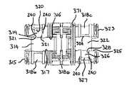
이제 도 4 내지 도 6을 참조하면, 힌지 유닛(3)은 중심축(70), 내부 링(71), 제 1 및 제 2 외부 링(72, 73), 및 2개의 단부 캡(74)을 포함한다. 내부 링(71)은 내부 힌지 요소로서 작용한다. 제 1 및 제 2 외부 링(72, 73)은 외부 링 요소로서 작용한다.
4 to 6, the
내부 링(71) 및 2개의 외부 링(72, 73)은, 외부 링들(72, 73)이 내부 링(71)의 어느 한쪽에 배치되는 상태로, 중심축(70) 상에 수용된다. 2개의 단부 캡(74)은 중심축(70)의 단부 면(75)들에 견고하게 장착된다. 단부 캡(74)들은 힌지 요소들(71, 72, 73)을 중심축(70) 상의 제 위치에 보유하고, 힌지 요소들(71, 72, 73)이 축(70)의 길이방향 축선을 따르는 방향으로 이동하는 것을 방지한다.
The
중심축(70)은 도 5에 도시된다. 중심축(70)은 세장형이며, 외부 링들(72, 73)이 둘레로 회전하는 길이방향 축선을 규정하므로, 하기에서 설명하는 바와 같이, 하우징부(5, 6)는 축(70)의 길이방향 축선을 중심으로 선회할 수 있다. 단부 면(75)들 사이에서 연장되는 중심축(70)을 통해 원통형 보어(76)가 형성된다.
The
본 실시예에 있어서, 중심축(70)은 기계가공된 알루미늄으로 형성되지만, 재료 및 제조 방법이 그것에 한정되지 않으며, 예컨대 중심축이 성형 또는 주조될 수 있거나, 및/또는 플라스틱 재료로 형성될 수 있음이 인식될 것이다. 본 실시예에서는 내부 링(71)이 중심축(70)에 대한 별도의 구성요소이지만, 내부 링(71)이 중심축(70)과 일체로 형성될 수 있음이 이해될 것이다.
In this embodiment, the
중심축(70)은 외부 면(77)을 갖는다. 중심축(70)의 단부 면(75)들 사이에서 축(70)의 길이방향 축선에 평행하게 연장되는, 정반대로 대향하는 2개의 리세스(78, 79)는 중심축(70)의 외부 면(77)에 형성된다. 각각의 리세스(78, 79)는 하부 면(80) 및 대향하는 측면들(81, 82)을 갖는다. 대항하는 측면들(81, 82)은, 하기에서 분명해지는 바와 같이, 힌지 요소들(71, 72, 73)용 단부 정지부로서 작용한다.
The
중심축(70)은 중심축(70)의 길이방향 축선을 따라 규정된 제 1 및 제 2 외부 구역(77b, 77c) 사이에 배치되는 내부 구역(77a)을 갖는다. 내부 구역(77a)의 폭은 내부 링(71)의 폭에 대응하고, 각각의 외부 구역(77b, 77c)의 폭은 외부 링들(72, 73) 각각의 폭에 대응한다. 본 실시예에 있어서, 각각의 링(71, 72, 73)은 동일한 폭을 갖지만, 링들의 폭이 변경될 수 있음이 이해될 것이다.
The
각각의 리세스(78, 79)의 대향하는 측면(81)들 중 하나에는 제 1 만입부(indent)(83)가 형성된다. 제 1 만입부(83)는 각각의 리세스(78, 79)의 제 1 외부 구역(77b)에 형성된다. 축(70)의 길이방향에 있어서 대향하는 측면(81)들에서의 제 1 만입부(83)의 폭은 제 1 외부 구역(77b)의 폭에 대응한다. 제 1 만입부(83)들은, 제 1 외부 구역(77b) 내의 리세스들(78, 79)의 대향하는 측면들(81, 82) 사이의 각도가 내부 구역(77a) 내의 대향하는 측면들(81, 82) 사이의 각도보다 크다는 것을 의미한다. 제 1 만입부(83)들 각각의 이면(back face)(84) 및 상응하는 대향 측면(82)들은, 하기에서 분명해지는 바와 같이, 제 1 외부 링(72)의 회전을 제한하기 위한 단부 정지부들로서 작용한다.
A
저지 요소로서 작용하는 자석(85)은 각각의 제 1 만입부(83)의 이면(87)에 형성된 중공부에 견고하게 장착된다. 저지 요소로서 작용하는 다른 자석(90)은 대향하는 측면(82)의 제 1 외부 구역(77b)에 형성된 중공부에 견고하게 장착되어, 제 1 만입부(83) 내의 자석(85)에 대향한다.
The
제 1 만입부(83)에 대하여 각각의 리세스(78, 79)의 대향하는 측면(82)들에는 제 2 만입부(86)가 형성된다. 제 2 만입부(86)는 각각의 리세스(78, 79)의 제 2 외부 구역(77c)에 형성된다. 축(70)의 길이방향에 있어서 대향하는 측면(81)들에서의 제 2 만입부(86)의 폭은 제 2 외부 구역(77c)의 폭에 대응한다. 각각의 리세스(78, 79)에 형성된 제 2 만입부(86)들은, 제 2 외부 구역(77c) 내의 리세스들(78, 79)의 대향하는 측면들(81, 82) 사이의 각도가 내부 구역(77a) 내의 대향하는 측면들(81, 82) 사이의 각도보다 크다는 것을 의미한다. 제 2 만입부(86)들 각각의 이면(87) 및 상응하는 대향 측면(81)들은, 하기에서 분명해지는 바와 같이, 제 2 외부 링(73)의 회전을 제한하기 위한 단부 정지부들로서 작용한다.
A second
저지 요소로서 작용하는 자석(88)은 각각의 제 2 만입부(86)의 이면(87)에 있는 중공부에 견고하게 장착된다. 저지 요소로서 작용하는 다른 자석(89)은 대향하는 측면(81)의 제 2 외부 구역(77c)에 형성된 중공부에 견고하게 장착되어, 제 1 만입부(83) 내의 자석(85)에 대향한다.
The
내부 링(71)은 외부 면(91) 및 내면(92)을 갖는다. 정반대로 대향하는 2개의 숄더(93)는 내면(92)으로부터 직립한다. 각각의 숄더(93)는 2개의 반경 방향으로 연장되는 단부 면들(94, 95) 및 단부 면들(94, 95) 사이에서 연장되는 숄더 상부 면(96)을 갖는다. 내부 링(71)이 중심축(70) 둘레로 수용될 수 있도록, 내부 링(71)의 내면(92)의 직경은 중심축(70)의 외부 면(77)의 직경에 대응한다.
The
2개의 숄더(93)는 내부 링(71)의 내면(92) 둘레에 아치형으로 형성된다. 숄더들 중 하나(93)의 단부 면(94)과 다른 숄더(93)의 단부 면(94) 사이의 각도는 중심축 리세스들의 측면들(81, 82) 사이의 각도에 대응한다. 따라서, 내부 링(71)이 중심축(70)의 내부 구역(77a) 위로 수용될 때, 각각의 리세스(78, 79)의 각각의 측면(81, 82)은 2개의 숄더(93)의 인접 단부 면(94)들에 인접해서, 중심축(70)을 중심으로 한 내부 링(71)의 회전이 방지된다. 유사하게, 내부 링(71)의 숄더 상부 면(96)들은 중심축 리세스들(78, 79)의 하부 면(80)에 놓이고, 내부 링(71)의 내면(92)은 내부 링(71)을 놓기 위해 중심축(70)의 외부 면(77)에 놓인다.
The two
내부 링(71)에는 2개의 레그 수용 캐비티(97)가 형성된다. 각각의 레그 수용 캐비티(97)는 내부 링 외부 면(91)으로부터 내부 링(71)의 숄더(93)들 중 하나로 연장된다. 2개의 레그 수용 캐비티(97)는 서로 평행하게 연장된다. 캐비티(97)들에 대한 개구들은 내부 링(71)의 외부 면(91)에 형성된다. 내부 링(71) 내의 캐비티(97)들은 끽연 물품 홀더의 2개의 베이스 레그(50, 51)를 수용하도록 구성된다. 보유 요소로서 작용하는 자석(98)은 각각의 레그 수용 캐비티(97)의 베이스에 견고하게 장착된다. 각각의 레그 수용 캐비티(97)의 깊이는 베이스 레그들(50, 51)의 길이에 대응하므로, 베이스 레그들(50, 51)이 캐비티(97)들에 수용될 때, 내부에 각각의 베이스 레그(50, 51)를 보유하기 위해, 각각의 베이스 레그(50, 51)의 단부에 있는 자석(52)은 각각의 캐비티(97) 내의 막대 자석(98) 쪽으로 끌어당겨져서 그 자석에 대항하여 놓인다(도 6 참조).
In the
내부 링(71)에는 2개의 레그 수용 캐비티(97)가 형성되어 있지만, 끽연 물품 홀더가 그로부터 연장되는 하나의 레그를 가지는 대안적인 실시예에서는, 하기에서 분명해지는 바와 같이, 내부 링(71)이 하나의 상응하는 레그 수용 캐비티(97)를 가질 것이다.
In an alternative embodiment in which the
각각의 외부 링(72, 73)은 외부 면(100) 및 내면(101)을 갖는다. 정반대로 대향하는 2개의 숄더(102)는 각각의 외부 링(72, 73)의 내면(101)으로부터 안쪽으로 확장한다. 각각의 숄더(102)는 2개의 단부 면(103, 104), 및 단부 면들(103, 104) 사이에서 연장되는 숄더 상부 면(105)을 갖는다. 하기에서 분명해지는 바와 같이, 외부 링들(72, 73)이 중심축(70) 둘레로 수용될 수 있게, 각각의 외부 링(72, 73)의 내면(101)의 직경은 중심축(70)의 외부 면(77)의 직경에 대응한다.
Each
숄더들 중 하나의 숄더(102)의 단부 면(103, 104)과 다른 숄더(102)의 단부 면(103, 104) 사이의 각도는 중심축 리세스들(78, 79)의 측면들(81, 82) 사이의 각도에 대응한다. 그러나, 대향하는 숄더들의 단부 면들(103, 104) 사이의 각도가 하나의 측면(81) 내의 제 1 만입부(83)의 이면(84)과 단부 정지부들로서 작용하는 리세스(78, 79)의 대향 측면(82) 사이의 각도보다 적다는 것이 인식될 것이다. 따라서, 제 1 외부 링(72)이 중심축(70)의 제 1 외부 구역(77b) 위로 수용되고, 제 2 외부 링(73)이 중심축(70)의 제 2 외부 구역(77c) 위로 수용될 때, 제 1 및 제 2 외부 링(72, 73) 각각의 숄더(102)는 상응하는 제 1 및 제 2 외부 구역(77b, 77c)을 중심으로 자유롭게 회전한다. 그러나, 중심축(70)을 중심으로 한 제 1 및 제 2 외부 링(72, 73) 각각의 회전은 상응하는 단부 정지부들에 대항하여 놓이는 숄더들(93)에 의해 제한된다.
The angle between the end surface 103,104 of one of the
제 1 외부 링(72)은 각각의 리세스(78, 79)의 하나의 측면(81)에 형성된 제 1 만입부(83) 내로 슬라이딩함으로써 일 방향으로 슬라이딩 및 회전할 수 있고, 제 2 외부 링(73)은 각각의 리세스(78, 79)의 대향하는 측면(82)에 형성된 제 2 만입부(86) 내로 슬라이딩함으로써 정반대 방향으로 슬라이딩 및 회전할 수 있음이 인식될 것이다.
The first
각각의 외부 링(72, 73)의 숄더 상부 면(105)들은 중심축 리세스들(78, 79)의 하부 면(80)에 대항하여 놓이고, 각각의 외부 링(72, 73)의 내면(101)은 각각의 외부 링(72, 73)을 놓기 위해 중심축(70)의 외부 면(77)에 대항하여 놓인다. 각각의 외부 링(72, 73)은 내부 링(71)에 대항하여 놓이며, 거기에 평행하게 놓인다(도 4 참조). 내부 및 외부 링들(71, 72, 73)이 중심축(70) 상에 수용될 때, 단부 캡(74)들은 링들(71, 72, 73)을 축(70) 상의 제 위치에 유지하기 위해 중심축(70)의 단부 면(75)들에 견고하게 장착된다. 따라서, 내부 링(71)은 축의 내부 구역(77a) 둘레로 배치되고; 제 1 외부 링(72)은 축의 제 1 외부 구역(77b) 둘레로 배치되고; 제 2 외부 링(73)은 축의 제 2 외부 구역(77c) 둘레로 배치된다. 중심축 상에 링들(71, 72, 73)을 보유하기 위한 대안적인 배열체를 구상할 수 있음이 이해될 것이다.
The shoulder upper surfaces 105 of each
2개의 레그 수용 캐비티(107)는 제 1 외부 링(72)에 형성된다. 각각의 레그 수용 캐비티(107)는 제 1 외부 링 외부 면(100)으로부터 제 1 외부 링(72)의 숄더(102)들 중 하나 내로 연장된다. 2개의 레그 수용 캐비티(107)는 서로 평행하게 연장되고, 캐비티(107)들에 대한 개구들은 제 1 하우징부(5)의 2개의 상응하는 레그(27, 28)를 수용하기 위해 제 1 외부 링(72)의 외부 면(100)에 형성된다. 보유 요소로서 작용하는 자석(108)은 각각의 레그 수용 캐비티(107)의 베이스에 견고하게 장착된다. 각각의 레그 수용 캐비티(107)의 깊이는 제 1 하우징부 레그들(27, 28)의 길이에 대응한다. 따라서, 레그들(27, 28)이 캐비티(107)들에 수용될 때, 각각의 레그(27, 28)를 내부에 보유하기 위해, 각각의 레그(27, 28)의 단부에 있는 자석(30)은 각각의 캐비티(107) 내의 자석(108) 쪽으로 끌어당겨져서 그 자석에 대항하여 놓인다(도 6 참조).
The two leg-receiving
2개의 레그 수용 캐비티(109)는 제 2 외부 링(73)에 형성된다. 각각의 레그 수용 캐비티(109)는 제 2 외부 링 외부 면(100)으로부터 제 2 외부 링(73)의 숄더(102)들 중 하나 내로 연장된다. 2개의 레그 수용 캐비티(109)는 서로 평행하게 연장되고, 캐비티(109)들에 대한 개구들은 제 2 하우징부(6)의 2개의 상응하는 레그(33, 34)를 수용하기 위해 제 2 외부 링(73)의 외부 면(100)에 형성된다. 보유 요소로서 작용하는 자석(110)은 각각의 레그 수용 캐비티(109)의 베이스에 견고하게 장착된다. 각각의 레그 수용 캐비티(109)의 깊이는 제 2 하우징부 레그들(33, 34)의 길이에 대응하므로, 레그들(33, 34)이 캐비티(109)들에 수용될 때, 내부에 각각의 레그(33, 34)를 보유하기 위해, 각각의 레그(33, 34)의 단부에 있는 자석(36)은 각각의 캐비티(109) 내의 자석(110) 쪽으로 끌어당겨져서 그 자석에 대항하여 놓인다(도 6 참조).
Two leg-receiving
제 1 및 제 2 외부 링(72, 73) 각각에 2개의 레그 수용 캐비티(107, 109)가 내부에 형성되어 있지만, 카트리지 유닛(2)의 제 1 및 제 2 하우징부(5, 6)가 그로부터 연장되는 하나의 레그를 갖는 대안적인 실시예에 있어서는, 제 1 및 제 2 외부 링(72, 73) 각각은 하나의 상응하는 레그 수용 캐비티를 갖게 된다.
The first and
저지 요소로서 작용하는 자석(111)은 제 1 외부 링(72)의 숄더들 중 하나의 숄더(102)의 단부 면들 중 하나의 단부 면(103)에 수용된다. 저지 요소로서 작용하는 다른 자석(112)은 제 1 외부 링(72)의 동 숄더(102)의 다른 단부 면(104)에 수용된다. 제 1 외부 링(72)이 축(70)의 제 1 외부 구역(77b) 상에 수용될 때, 다른 단부 면(104)에 수용된 자석(112)은 측면(81)의 제 1 만입부(83)의 이면(84)에 수용된 자석(85)에 대면하도록 위치되고, 동 숄더(102)의 단부 면(103)에 수용된 자석(111)은 다른 측면(82)에 수용된 자석(90)에 대면하도록 위치된다.
The magnet 111 acting as a blocking element is received in one
유사하게, 저지 요소로서 작용하는 자석(113)은 제 2 외부 링(73)의 숄더들 중 하나의 숄더(102)의 단부 면들 중 하나의 단부 면(103)에 수용된다. 저지 요소로서 작용하는 다른 자석(114)은 제 2 외부 링(73)의 동 숄더(102)의 다른 단부 면(104)에 수용된다. 제 2 외부 링(73)이 축(70)의 제 2 외부 구역(77c) 상에 수용될 때, 단부 면(103)에 수용된 자석(113)은 다른 측면(82)에 수용된 자석(89)에 대면하도록 위치되고, 동 숄더(102)의 다른 단부 면(104)에 수용된 다른 자석(112)은 측면(81)의 제 1 만입부(83)의 이면(84)에 수용된 자석(88)에 대면하도록 위치된다.
Similarly, the
상기에서는, 대면하는 자석들이 저지 요소들로서 사용되고 있지만, 다른 저지 배열체들이 사용될 수 있음이 인식될 것이다. 예컨대, 대면하는 저지 요소들 중 하나는 대면하는 자석 쪽으로 끌어당겨지는 스틸(steel)부일 수 있다.
It will be appreciated that while in the above, facing magnets are used as blocking elements, other blocking arrangements can be used. For example, one of the opposing blocking elements may be a steel part pulled toward the facing magnet.
이제, 상기 끽연 물품용 패키지의 용도를 도 1 내지 도 6을 참조해서 기술한다.
Now, the use of the package for a smoking article will be described with reference to Figs. 1 to 6. Fig.
힌지 유닛(3) 및 카트리지 유닛(2)은 초기에는 서로 분리되어 있다. 유저가 한 손에는 힌지 유닛(3)을, 다른 손에는 카트리지 유닛(2)을 파지하고, 두 유닛을 서로를 향해 끌어당긴다. 유저는 카트리지 유닛 제 1 하우징부(5), 제 2 하우징부(6), 및 물품 홀더의 레그들(27, 28, 33, 34) 및 베이스 레그들(50, 51)을, 제 1 및 제 2 외부 링(72, 73) 및 내부 링(71)의 레그 수용 캐비티들(107, 97, 109)과 각각 정렬시키고, 레그들을 레그 수용 캐비티들에 삽입한다. 레그들 및 레그 수용 캐비티들은 함께 부착 수단 또는 유닛을 형성한다. 즉, 레그들 및 레그 수용 캐비티들은 힌지 유닛(3)을 카트리지 유닛(2)에 부착하는 수단을 제공한다. 제 1 하우징부(5)의 레그들(27, 28)은 제 1 외부 링(72)에 부착되고, 제 2 하우징부(6)의 레그들(33, 34)은 제 2 외부 링(73)에 부착되고, 끽연 물품 홀더의 베이스 레그들(50, 51)은 내부 링(71)에 부착된다.
The
레그들이 레그 수용 캐비티들 내로 슬라이딩되면, 레그 및 베이스 레그(27, 28, 33, 34, 50, 51) 각각의 단부에 있는 자석들(30, 36, 52)이 레그 수용 캐비티(107, 97, 109) 각각의 베이스에 장착된 상응하는 자석(108, 110, 98) 쪽으로 끌어당겨진다. 자석들은 레그들을 레그 수용 캐비티들에 보유해서 힌지 유닛(3)과 카트리지 유닛(2)의 부착을 유지하도록 작용하는 보유 수단 또는 보유 유닛을 형성한다. 제 1 및 제 2 하우징부(5, 6)의 아치형 저부 면(14, 20)은 외부 링들(72, 73)의 아치형 외부 면(100)에 대항하여 놓인다. 힌지 유닛과 카트리지 유닛이 부착되어서 조립된 상태로 되면, 끽연 물품용 패키지는 리세스들(78, 79)의 측면(81)들에 배치된 자석(88)들이 각각의 외부 링(72, 73)의 숄더(102)들 중 하나의 단부 면(103)들에 배치된 상응하는 자석들(111, 113)에 인접하는 것에 의해 폐쇄 상태로 유지된다. 자석들은 패키지가 폐쇄 상태와 개방 상태 사이에서 이동하는 것을 저지하기 위한 저지 요소들로서 작용한다.
When the legs slide into the leg accommodating cavities, the
이후, 유저는 카트리지 유닛(2)의 제 1 및 제 2 하우징부(5, 6)를 파지해서, 하우징부들(5, 6)을 서로로부터 멀리 끌어당긴다. 제 1 및 제 2 하우징부(5, 6)는 서로로부터 멀리 가압되고, 제 1 및 제 2 하우징부(5, 6)의 레그들(27, 28, 33, 34)은 외부 링들(72, 73)에 대하여 작용해서 이들을 가압하여 축(70)을 중심으로 회전시킨다. 따라서, 보유 요소들(88, 111, 113)의 보유력이 극복되고, 외부 링들(72, 73)은 축(70)을 중심으로 회전하며, 제 1 및 제 2 하우징부(5, 6)는 서로로부터 멀리 선회된다. 유사하게, 끽연 물품 홀더는 축(70)에 견고하게 장착되고 축(70)을 중심으로 회전하는 것이 방지되므로, 외부 링들(72, 73)은 끽연 물품 홀더로부터 멀리 선회되어, 외부 하우징(4)에 의해 규정된 끽연 물품 수용 공간(7)을 노출시킨다.
Thereafter, the user grasps the first and
제 1 및 제 2 외부 링(72, 73)이 축(70)을 중심으로 회전함에 따라, 숄더(102)들이 리세스들(78, 79)의 제 1 및 제 2 외부 구역(77b, 77c)에서 슬라이딩하고, 제 1 외부 링(72)의 숄더(102)들은 각각의 리세스(78, 79)의 대향하는 측면(81)들 중 하나에 형성된 제 1 만입부(83)들 내로 슬라이딩한다. 유사하게, 제 2 외부 링(73)의 숄더(102)들은 각각의 리세스(78, 79)의 다른 대향하는 측면(81)들에 형성된 제 2 만입부(86)들 내로 슬라이딩한다. 제 1 및 제 2 외부 링(72, 73)의 회전이 계속됨에 따라, 숄더(102)들은 단부 정지부들로서 작용하는 만입부들(83, 86)의 이면(82, 87)에 인접한다. 단부 정지부들은 축(70)을 중심으로 한 제 1 및 제 2 외부 링(72, 73)의 회전을 제한한다. 이후, 패키지는 완전 개방 상태로 되고, 끽연 물품 수용 공간(7)에 포함된 끽연 물품에 접근 가능하다.
As the first and second
숄더(102)들은, 각각의 제 1 및 제 2 만입부(83, 86) 중 하나의 이면(82, 87)에 배치된 자석(88)들이 서로를 향해 끌어당겨져 있는 숄더(102)의 대향하는 단부 면 내의 자석들(112, 114)을 끌어당기는 것에 의해, 만입부들(83, 86)의 이면들(82, 87)과 인접하도록 당겨진다. 또한, 저지 요소들로서 작용하는 자석들은 패키지가 개방 상태와 폐쇄 상태 사이에서 이동하는 것을 저지한다.
The
제 1 및 제 2 하우징부(5, 6)가 폐쇄 위치에 있을 때, 끽연 물품 홀더의 베이스부들(38, 40)에 의해 유지된 끽연 물품들은 서로 평행하게 정렬된다. 외부 베이스부(40)에 배치된 끽연 물품들의 각각의 외부열의 상단부는 제 1 및 제 2 하우징부(5, 6) 각각의 후방 벽(9, 16)에 인접한다. 하우징부들이 끽연 물품 홀더 및 서로로부터 멀리 선회되면, 하우징부들(5, 6)의 후방 벽들(9, 16)은 끽연 물품들로부터 멀리 선회된다. 따라서, 내부에 배치된 끽연 물품들과 함께 끽연 물품 홀더 외부 베이스부(40)들은 그들이 장착되는 지지 플레이트(41)의 탄성으로 인해 중간 베이스부(38)에 대하여 선회할 수 있다. 외부 베이스부(40)들 상의 자석(63)들은 베이스 지지부(42)의 2개의 외부 부분(47) 상의 상응하는 자석(48)들 쪽으로 끌어당겨진다. 자석들은 안내 요소로서 작용한다. 따라서, 2개의 외부 베이스부(40)는 중간 베이스부(38)에 대하여 선회하도록 가압된다. 이후, 2개의 외부 베이스부(40)는 중간 베이스부(38)에 대하여 비스듬히 연장된다. 따라서, 2개의 외부 베이스부(40)에 수용된 끽연 물품들은 중간 베이스부(38)에 수용된 끽연 물품들로부터 멀리 바깥쪽으로 벌어진다(도 2 참조).
When the first and
이후, 유저는 끽연 물품을 패키지로부터 용이하게 제거할 수 있다. 패키지를 그 개방 상태로부터 그 폐쇄 상태로 이동시키기 위해, 하우징부들은 서로를 향해 가압되고, 외부 링들(72, 73)은 외부 링들(72, 73)의 숄더(102)들이 리세스들(78, 79)의 측면들(81, 82)에 인접할 때까지 정반대 방향으로 슬라이딩한다.
Thereafter, the user can easily remove the smoking article from the package. The housing portions are urged toward each other to move the package from its open state to its closed state and the
카트리지 유닛(2)에 수용된 모든 끽연 물품이 제거되어 있으면, 카트리지 유닛(2)을 폐기할 수 있다. 이렇게 하기 위해, 유저는 그 폐쇄 위치에서 힌지 유닛을 거기에 장착된 카트리지로부터 멀리 끌어당긴다. 각각의 상응하는 레그 수용 캐비티의 베이스에 있는 대향하는 보유 요소들에 작용하는 각각의 레그의 단부에 있는 보유 요소들의 보유력이 극복된다. 따라서, 보유 수단이 해제되고, 각각의 레그는 각각의 캐비티에서 끌어당겨진다. 이후, 힌지 유닛(3)은 보유되며, 카트리지 유닛(2)은 환경 친화적인 방식으로 처리될 수 있다. 상기 배열체의 장점은, 패키징의 일부가 보유되므로, 패키지 모두가 처리되어야 하는 것은 아니라는 점이다. 또한, 힌지는 종래의 팩(pack)보다 더 강성(rigid)이기 때문에, 힌지의 고장이 최소화된다.
If all the smoking articles stored in the
상술한 실시예에 있어서는, 제 1 및 제 2 하우징부(5, 6)와 끽연 물품 홀더가 각각 그들로부터 연장되는 2개의 레그를 갖고 있지만, 대안적인 실시예에 있어서는, 제 1 및 제 2 하우징부(5, 6) 및 끽연 물품 홀더 각각이 그들로부터 연장되는 하나의 레그를 가지고, 그에 따라 각각의 레그가 제 1 및 제 2 외부 링(72, 73) 및 내부 링(71) 각각에 형성된 단일의 상응하는 레그 수용 캐비티에 수용된다는 것이 인식될 것이다. 또한, 제 1 및 제 2 하우징부(5, 6) 및 끽연 물품 홀더를 제 1 및 제 2 외부 링(72, 73) 및 내부 링(71)에 제각기 부착하는 수단이 상응하는 리세스에 수용된 하나 또는 그 초과의 레그에 한정되는 것은 아니며, 대안적인 부착 수단이 사용될 수 있음이 인식될 것이다.
In the above-described embodiment, the first and
이제, 도 7 및 도 8을 참조하면, 상술한 바와 같은 복수 개의 카트리지 유닛(2)을 유지하는 홀더(120)가 도시된다. 홀더(120)는 세장형 본체(121) 및 본체(121)로부터 연장되는 장착 요소(122)를 포함한다. 세장형 본체(121)는 아치형 상부 면(123)을 가진 빔(beam)이다. 아치형 상부 면(123)은 제 1 및 제 2 하우징부(5, 6)의 아치형 저부 면(14, 20)의 호에 대응하므로, 하기에서 분명해지는 바와 같이, 카트리지 유닛(2)들은 아치형 상부 면(123)에 대하여 위치설정될 수 있다.
7 and 8, a holder 120 for holding a plurality of
9개 그룹의 구멍들(도시되지 않음)이 홀더(120)의 아치형 상부 면(123)에 형성되고, 세장형 본체(121)를 따라 배치된다. 각 그룹의 구멍들은 서로 이격되는 6개의 구멍을 포함한다. 각 그룹의 구멍들에서의 구멍들의 위치는 카트리지 유닛(2)으로부터 연장되는 레그들의 배열체에 대응하므로, 카트리지 유닛(2)이 구멍들의 그룹들 중 하나와 정렬될 때, 카트리지 유닛(2)으로부터 연장되는 레그들 각각은 홀더(120)의 세장형 본체(121)에 형성된 상응하는 구멍에 수용될 수 있다. 카트리지 유닛(2)의 제 1 및 제 2 하우징부(5, 6)가 홀더 내의 구멍들에 수용되는 각각의 레그로 인해 서로에 대하여 회전하는 것이 방지되기 때문에, 카트리지는 홀더(120)에 부착될 때 폐쇄 위치로 보유된다는 것이 인식될 것이다.
Nine groups of holes (not shown) are formed in the arcuate
본 실시예에 있어서는, 9개의 그룹의 구멍들이 도시되어 있기 때문에, 9개의 카트리지 유닛(2)을 홀더(120)에 장착할 수 있다. 그러나, 구멍들의 그룹의 수는 원하는 개수의 장착된 카트리지 유닛(2)들에 의존한다는 것이 인식될 것이다. 유사하게, 각 그룹의 구멍들에는 6개의 구멍이 형성되어 있지만, 대안적인 실시예에 있어서는, 각 그룹의 구멍들이 3개의 레그만을 갖는 카트리지 유닛(2)의 3개의 레그를 수용하도록 위치되는 3개의 구멍을 갖는다는 것이 인식될 것이다.
In this embodiment, since nine groups of holes are shown, it is possible to mount the nine
장착 요소(122)는 세장형 본체(121)의 일단부로부터 연장되는 로드이다. 장착 요소(122)는 원통형이며, 힌지 유닛(3)의 중심축(70)을 통해 형성된 원통형 보어(76)의 직경에 대응하는 직경을 갖는다. 따라서, 힌지 유닛(3)은 장착 요소(122) 상에 슬라이드가능하게 수용된다.
The mounting
사용시에, 홀더(120)에는 거기에 장착된 카트리지 유닛(2)들의 어레이가 제공된다. 힌지 유닛(3)은 장착 요소(122) 상에서 슬라이딩되고, 이후, 유저는 홀더(120)의 본체(121) 내의 구멍들로부터 카트리지 유닛(2)의 레그들을 끌어당기는 제거력을 가함으로써 카트리지 유닛(2)들 중 하나를 홀더(120)로부터 옮길 수 있다. 이후, 유저는 카트리지 유닛(2)의 레그들을 상응하는 레그 수용 캐비티들(97, 107, 109) 내로 정렬 및 삽입해서, 카트리지 유닛(2)을 힌지(3)에 부착한다. 뒤이어, 조립된 패키지는 홀더(120)로부터 슬라이딩되고, 유저는 상술한 바와 같이 패키지를 사용할 수 있다.
In use, the holder 120 is provided with an array of
이제, 도 9 내지 도 37을 참조하면, 끽연 물품용 패키지의 다른 실시예가 도시된다. 끽연 물품용 패키지의 하기의 실시예들은 일반적으로 상술한 끽연 물품용 패키지의 실시예들과 동일하다.
Referring now to Figures 9-37, another embodiment of a package for a smoking article is shown. The following embodiments of packages for smoking articles are generally the same as those of the packages for smoking articles described above.
후술하는 끽연 물품용 패키지의 실시예들의 양태들, 특징들 및 요소들은 상술한 끽연 물품용 패키지의 실시예들의 양태들, 특징들 및 요소들과 결합하여 사용될 수 있음이 이해될 것이다.
It will be appreciated that aspects, features, and elements of embodiments of packages for smoking articles described below may be used in combination with aspects, features and elements of embodiments of packages for smoking articles described above.
도 9 및 도 10에는, 카트리지 유닛(202) 및 힌지 유닛(203)을 포함하는 끽연 물품용 패키지(201)가 도시된다. 도 9에서, 패키지(201)는 카트리지 유닛(202)에 수용된 끽연 물품(208)들에 접근할 수 있는 개방 상태로 도시된다. 따라서, 끽연 물품(208)들은 패키지(201)로부터 제거될 수 있다. 도 10에서, 패키지(201)는 카트리지 유닛(202)에 수용된 끽연 물품(208)들이 카트리지 유닛(202)에 의해 에워싸이는 폐쇄 상태로 도시된다. 따라서, 끽연 물품(208)들은 카트리지 유닛(202)에 의해 보호된다. 힌지 유닛(203)은 원통형이다. 카트리지 유닛(202)은 힌지 유닛(203)에 장착된다. 힌지 유닛의 직경은 카트리지 유닛의 깊이에 대응한다. 즉, 힌지 유닛의 직경은 카트리지 유닛이 폐쇄 상태에 있을 때 카트리지 유닛의 깊이와 동일하다.
9 and 10, a
카트리지 유닛(202)은 힌지 유닛(203)에 제거 가능하게 부착된다. 즉, 카트리지 유닛(202) 및 힌지 유닛(203)은 서로 분리될 수 있다. 카트리지 유닛(202)은 끽연 물품들을 포함하도록 구성된다. 힌지 유닛(203)은, 카트리지 유닛(202)이 힌지 유닛(203)에 장착될 때, 카트리지 유닛(202)을 개방시킬 수 있게 구성된다. 힌지 유닛(203)은, 힌지 유닛(203)이 카트리지 유닛(202)에 부착될 때, 카트리지 유닛(202)을 개방시킬 수 있게 하는 키(key)로서 작용한다.
The
카트리지 유닛(202)은 외부 쉘 또는 하우징(204)을 갖는다. 하우징(204)은, 하우징(204)을 형성하도록 합쳐지는, 제 1 및 제 2 하우징부(205, 206)에 의해 형성된다. 하우징(204)은 끽연 물품 수용 공간(207)을 규정한다. 끽연 물품(208)은 끽연 물품 수용 공간(207)에 수용되고, 패키지가 그 폐쇄 위치에 있을 때 하우징(204)에 의해 감싸진다. 제 1 및 제 2 하우징부(205, 206)는 끽연 물품 수용 공간(207)으로의 접근을 제공하도록 분리될 수 있다. 즉, 카트리지 유닛(202)은 폐쇄 상태와 개방 상태 사이에서 이동 가능하다.
The
카트리지 유닛(202)은 세장형이며, 상단부와 하단부 사이에서 연장된다. 카트리지 유닛(202)의 하단부는 힌지 유닛(203)에 장착될 수 있다. 제 1 및 제 2 하우징부(205, 206) 각각은 그 하단부에서 힌지 유닛(203)에 장착될 수 있다. 2개의 하우징부(205, 206)는 힌지 유닛(203)의 길이방향 축선을 중심으로 개별적으로 회전할 수 있다. 따라서, 카트리지 유닛(202)은 도 10에 도시된 바와 같은 폐쇄 위치와 도 9에 도시된 바와 같은 개방 위치 사이에서 이동 가능하다. 폐쇄 상태에 있어서, 하우징부들(205, 206)은, 카트리지 유닛(202)에 수용된 끽연 물품(208)들이 하우징(204)에 의해 에워싸이도록, 서로에 대하여 인접해 있다. 개방 상태에 있어서, 하우징부들(205, 206)은 힌지 유닛(203)을 중심으로 서로로부터 멀리 힌지결합되어 있다. 따라서, 끽연 물품 수용 공간(207)에 배치된 끽연 물품(208)들에 접근할 수 있다.
The
특히 도 11 내지 도 14를 참조하면, 카트리지 유닛(202)의 제 1 하우징부(205)는 후방 벽(209), 2개의 대향하는 측벽(210) 및 상부 벽(211)을 갖는다. 제 1 하우징부(205)의 2개의 측벽(210)은 후방 벽(209)의 대향하는 에지들로부터 연장되며, 평행하지만 서로 이격되게 연장된다. 상부 벽(211)은 후방 벽 및 측벽들(209, 210)의 상단부로부터 연장된다.
11-14, the
제 1 하우징부(205)는 또한 저부 벽(213)을 갖는다. 저부 벽(213)은 후방 벽 및 측벽(209, 210)의 하단부로부터 연장된다. 저부 벽의 연장부(213a)는 후방 벽(209)으로부터 측벽들 및 상부 벽(210, 211)보다 더 연장된다. 저부 벽(213)은 아치형 저부 면(214)을 규정한다. 아치형 저부 면(214)은 저부 벽(213)의 일부를 형성하는 리브(rib)(213b)들의 자유 단부에 의해 규정된다. 그러나, 아치형 저부 면(214)이 아치형 표면에 의해 형성될 수 있음이 이해될 것이다. 제 1 하우징부(205)의 저부 면(214)은 힌지 유닛(203)의 외부 면(212)의 둘레에 대응한다. 따라서, 하기에서 분명해지는 바와 같이, 힌지 유닛(203)의 일부는 저부 면(214)에 대하여 인접해서 놓이도록 저부 벽(213)에 의해 규정된 채널에 수용될 수 있다.
The
제 1 하우징부(205)의 자유 에지(222)는 제 1 하우징부(205)의 측벽 및 상부 벽(210, 211)의 외부 에지에 의해 규정된다. 제 1 하우징부(205)는 자유 에지(222)를 지나 돌출하는 제 1 및 제 2 아암(221a, 221b)(도 15에서는, 제 2 아암(221b)이 제 1 아암(221a) 뒤로 연장됨)을 갖는다. 제 1 및 제 2 아암(221a, 221b)은 대향하는 측벽(210)들에 평행하게 연장된다. 아암들(221a, 221b)은 아치형 상부 및 하부 에지를 갖는다. 상부 및 하부 에지의 호는 저부 면(214)의 호에 대응한다. 아암들(221a, 221b)은 서로 이격되며, 측벽(210)들에 인접하여 배치된다. 제 1 아암(221a)은 인접하는 측벽(210)에 인접해 있다. 제 1 아암(221a)은 그 인접하는 측벽(210)에 일체로 형성될 수 있다. 제 2 아암(221b)은 인접하는 측벽(210)으로부터 이격되므로, 제 2 하우징부(206)의 제 1 아암은 제 2 아암(221b)과 그 인접하는 측벽(210) 사이에 제공된 갭(gap) 내로 슬라이딩할 수 있다.
The
유사하게, 카트리지 유닛(202)의 제 2 하우징부(206)는 후방 벽(216), 2개의 대향하는 측벽(217) 및 상부 벽(218)을 갖는다. 제 2 하우징부(206)의 2개의 측벽(217)은 후방 벽(216)의 대향하는 에지들로부터 연장되며, 평행하지만 서로 이격되게 연장된다. 상부 벽(218)은 후방 벽 및 측벽들(216, 217)의 상단부로부터 연장된다.
Similarly, the
제 2 하우징부(206)는 또한 저부 벽(219)을 갖는다. 제 2 하우징부(206)의 저부 벽(219)은 후방 벽 및 측벽(216, 217)의 하단부로부터 연장된다. 저부 벽의 연장부(219a)는 측벽 및 상부 벽(217, 218)보다 후방 벽(216)으로부터 더 연장된다. 저부 벽(219)은 아치형 저부 면(220)을 규정한다. 아치형 저부 면(220)은 저부 벽(219)의 일부를 형성하는 리브(219b)들의 자유 단부에 의해 규정된다. 그러나, 아치형 저부 면(220)이 아치형 표면에 의해 형성될 수 있음이 이해될 것이다. 제 2 하우징부(206)의 저부 면(220)은 힌지 유닛(203)의 외부 면(212)의 둘레에 대응한다. 따라서, 하기에서 분명해지는 바와 같이, 힌지 유닛(203)의 일부는 저부 면(214)에 대하여 인접해서 놓이도록 저부 벽(213)에 의해 규정된 채널에 수용될 수 있다.
The
제 2 하우징부(206)의 자유 에지(223)는 제 2 하우징부(206)의 측벽들 및 상부 벽(217, 218)의 외부 에지에 의해 규정된다. 제 2 하우징부(206)는 자유 에지(223)를 지나 돌출하는 제 1 및 제 2 아암(224a, 224b)을 갖는다. 제 1 및 제 2 아암(224a, 224b)은 대향하는 측벽(210)들에 평행하게 연장된다. 아암들(224a, 224b)은 아치형 상부 및 하부 에지를 갖는다. 상부 및 하부 에지의 호는 저부 면(214)의 호에 대응한다. 아암들(224a, 224b)은 서로 이격되며, 측벽(217)들에 인접하여 배치된다. 제 1 아암(224a)은 인접하는 측벽(217)에 인접해 있다. 제 1 아암(224a)은 그 인접하는 측벽(217)에 일체로 형성될 수 있다. 제 2 아암(224b)은 인접하는 측벽(217)으로부터 이격되므로, 제 1 하우징부(205)의 제 1 아암(221a)은 제 2 하우징부(206)의 제 2 아암(224b)과 그 인접하는 측벽(217) 사이에 제공된 갭 내로 슬라이딩할 수 있다.
The
제 1 및 제 2 하우징부(205, 206)가 합쳐지면, 이들 하우징부는 카트리지 유닛(202)의 하우징(204)을 형성한다. 제 1 및 제 2 하우징부(205, 206)의 제 1 아암들(221a, 224a)은 상응하는 제 1 및 제 2 하우징부(205, 206)의 제 2 아암들(221b, 224b)에 겹친다. 하우징부들(205, 206)이 힌지 유닛(203)의 길이방향 축선을 중심으로 서로에 대하여 선회될 때, 각각의 제 2 아암(221b, 224b)과 그 인접하는 측벽(210, 217) 사이에 규정된 갭 내에서, 제 1 및 제 2 하우징부(205, 206)의 제 1 아암들(221a, 224a)은 상응하는 제 1 및 제 2 하우징부(205, 206)의 제 2 아암들(221b, 224b)을 따라 슬라이딩한다.
When the first and
카트리지 유닛(202)이 조립될 때, 제 1 하우징부 저부 벽(213)의 연장부(213a)는 대향하는 제 2 하우징부(206)의 저부 벽(219)의 일부와 겹친다. 유사하게, 제 2 하우징부 저부 벽(219)의 연장부(219a)는 대향하는 제 1 하우징부(205)의 저부 벽(213)의 일부와 겹친다. 제 1 하우징부(205)의 저부 벽(213) 및 제 2 하우징부(206)의 저부 벽(219)은 함께 카트리지 유닛(202)의 바닥 단부를 형성한다. 카트리지 유닛(202)의 바닥 단부는 실질적으로 아치형 단면을 가진 세장형 채널(230)을 규정한다. 채널(230)은 그 안에 부분적으로 힌지 유닛(203)을 수용하도록 구성된다.
When the
패키지(201)가 그 폐쇄 위치에 있을 때, 제 1 및 제 2 하우징부(205, 206)는 끽연 물품 수용 공간(207)을 에워싸도록 합쳐진다. 제 1 하우징부(205)의 자유 에지(222)는 제 2 하우징부(206)의 자유 에지(223)에 인접해 있다. 제 1 하우징부(205)는 자유 에지(222)를 따라 연장되는 내부 립(225)을 갖는다. 내부 립(225)은 제 1 하우징부(205)의 외부 면으로부터 오프셋된다. 내부 립(225)은 부분적으로 제 2 하우징부(206)에 의해 수용되도록 구성된다. 즉, 내부 립(225)은, 패키지가 그 폐쇄 위치에 있을 때, 제 2 하우징부(206)의 자유 에지(223)와 겹치도록 배치된다. 제 2 하우징부(206)의 자유 에지(223)는 자유 에지(223)의 내부측을 따라 연장되는 리세스부(226)를 갖는다. 제 1 및 제 2 하우징부(205, 206)가 합쳐질 때, 제 1 하우징부(205)의 내부 립(225)은 제 2 하우징부(206)의 자유 에지(223)의 리세스부(226)에 대항하여 놓이도록 배치된다.
When the
제 2 하우징부(206)의 상단부에는 래치(latch)가 형성된다. 래치는 잠금 돌출부(227) 및 잠금 노치(도시되지 않음)를 포함한다. 잠금 돌출부(227)는 제 2 하우징부(206)의 자유 에지(223)로부터 연장되는 플랜지(228) 상에 형성된다. 플랜지(228)는 내부 립(225)으로부터 연장된다. 잠금 노치(도시되지 않음)는 제 1 하우징부(205)의 내부 립(225)의 내부측에 형성된다. 제 1 및 제 2 하우징부(205, 206)가 합쳐질 때, 잠금 돌출부(227)와 잠금 노치는 서로 결합하도록 구성된다.
A latch is formed at an upper end of the
래치는 카트리지 유닛(202)의 상단부를 폐쇄 위치에 유지하도록 구성된다. 즉, 래치는 카트리지 유닛 잠금 배열체의 일부를 형성한다. 하기에서 분명해지는 바와 같이, 카트리지 유닛(202)이 힌지 유닛(203)으로부터 분리될 때, 카트리지 유닛 잠금 배열체는 카트리지 유닛을 폐쇄 위치에 잠금하도록 구성된다. 따라서, 힌지 유닛(203)이 카트리지 유닛(202)으로부터 분리될 때, 카트리지 유닛(202) 내에 보유된 물품들에 접근할 수 없다. 카트리지 유닛(202)의 상단부에서의 래치는 제 1 및 제 2 하우징부(205, 206)의 상단부들을 서로 결합 상태로 유지하도록 작용한다.
The latch is configured to hold the upper end of the
상술한 실시예에서는, 잠금 돌출부가 제 2 하우징부 상에 형성되고 잠금 리세스가 제 1 하우징부 상에 형성되어 있지만, 잠금 돌출부는 제 1 하우징부 상에 형성되고 잠금 리세스는 제 2 하우징부 상에 형성될 수 있음이 이해될 것이다. 대안으로서, 제 1 및 제 2 하우징부(205, 206)의 상단부들을 서로 접촉상태로 보유하기 위해 다른 래칭 배열체가 사용될 수 있다. 예컨대, 래치는, 카트리지 유닛(202)이 제 1 및 제 2 하우징부(205, 206)가 서로 인접하는 그 폐쇄 위치에 있을 때, 제 1 잠금 돌출부가 위에 놓이는 제 2 잠금 돌출부를 포함할 수 있다.
In the above-described embodiment, although the lock projection is formed on the second housing portion and the lock recess is formed on the first housing portion, the lock projection is formed on the first housing portion and the lock recess is formed on the second housing portion Lt; / RTI > Alternatively, other latching arrangements may be used to retain the upper ends of the first and
이제, 도 12 및 도 15를 참조하면, 제 1 하우징부(205)는 그 하단부로부터 연장되는 레그(229)를 갖는다. 레그(229)는 제 1 결합 레그를 형성한다. 제 1 결합 레그(229)는 카트리지 유닛(202)의 하단부에서 채널(230) 내로 돌출한다. 제 1 결합 레그(229)는 제 1 하우징부 저부 벽(213)으로부터 연장된다. 제 1 결합 레그(229)는 제 1 하우징부 저부 벽(213)의 연장부(213a)로부터 연장된다.
Referring now to Figures 12 and 15, the
유사하게, 제 2 하우징부(206)는 그 하단부로부터 연장되는 레그(232)를 갖는다. 레그(232)는 제 2 결합 레그를 형성한다. 제 2 하우징부 레그(232), 또는 제 2 레그(232)는 카트리지 유닛(202)의 하단부에서 채널(230) 내로 돌출한다. 제 2 결합 레그(232)는 제 2 하우징부 저부 벽(219)으로부터 연장된다. 제 2 결합 레그(232)는 제 2 하우징부 저부 벽(219)의 연장부(219a)로부터 연장된다.
Similarly, the
카트리지 유닛(202)이 조립될 때, 제 1 및 제 2 결합 레그(229, 232)는 카트리지 유닛(202)의 하단부에서 채널(230) 내로 연장되지만, 제 1 및 제 2 하우징부(205, 206)의 후방 벽들(209, 216)의 하부 에지로부터는 오목해진다. 제 1 및 제 2 결합 레그(229, 232)는 서로 이격된다. 카트리지 유닛(202)이 그 폐쇄 위치에 있을 때, 결합 레그들(229, 232)은 서로 평행하게 연장된다. 결합 레그들(229, 232)은 카트리지 유닛(202)의 아치형 바닥 단부로부터 방사상으로 연장된다.
When the
제 1 결합 레그(229)는 대향하는 측면들에 형성된 2개의 홈(233)을 갖는다. 각각의 홈(233)은 결합 면(234)을 형성한다. 결합 면(234)은 홈(233)의 하면에 의해 형성된다. 유사하게, 제 2 결합 레그(232)는 대향하는 측면들에 형성된 2개의 홈(235)을 갖는다. 각각의 홈(235)은 결합 면(236)을 형성한다. 결합 면(236)은 홈(235)의 하면에 의해 형성된다. 하기에서 분명해지는 바와 같이, 각각의 홈(233, 235)은 힌지 유닛(203) 상에 결합 요소(240)(도 22 및 도 23 참조)를 수용하도록 구성된다. 따라서, 제 1 및 제 2 결합 레그(229, 232)가 힌지 유닛(203)에 수용될 때, 각각의 결합 요소(240)는 상응하는 결합 면(234, 236)에 대항하여 놓일 수 있다. 결합 면들(234, 236)은 힌지 유닛(203)으로부터 결합 레그의 제거 방향에 대하여 비스듬한 각도로 연장하도록 구성된다.
The
본 배열체에 있어서, 홈들(233, 235)은 제 1 및 제 2 결합 레그(229, 232)의 전면 및 후면 사이에서 연장된다. 결합 면들(234, 236)은 결합 수단 또는 유닛의 일부를 형성한다. 결합 수단은 힌지 유닛(203)을 카트리지 유닛(202)과 결합하도록 구성된다. 즉, 결합 수단은, 카트리지 유닛이 내부에 수용된 끽연 물품들에 접근할 수 있게 하는 개방 상태에 있을 때, 카트리지 유닛(202)으로부터 힌지 유닛(203)의 제거를 방지하도록 배치된다.
In this arrangement, the
본 실시예에서는, 결합 면들(234, 236)이 결합 레그들(229, 232)에서 홈들에 의해 형성되지만, 대안적인 배열체들을 구상할 수 있음이 이해될 것이다. 예컨대, 결합 면들(234, 236)은 결합 레그들(229, 232) 상에 돌출부들에 의해 형성될 수 있다. 또한, 본 배열체에서는, 각각의 레그(229, 232)에 2개의 홈이 형성되어서 각각의 보유 요소(233, 234)를 형성하고 있지만, 대안적인 배열체에서는, 각각의 레그에는 단일의 홈만이 형성될 수 있다. 결합 수단은 단일의 레그에만 관련될 수 있다.
It will be appreciated that, in the present embodiment, the engagement surfaces 234, 236 are formed by the grooves in the
제 1 결합 레그(229)는 제 1 하우징부(205)의 하나의 측벽(210)에 인접하지만, 그로부터 약간 안쪽에 배치된다. 제 2 결합 레그(232)는 제 2 하우징부(206)의 대향하는 측벽(217)에 인접하되, 그로부터 약간 안쪽에 배치된다.
The
특히, 도 12 내지 도 19를 참조하면, 카트리지 유닛(202)은 끽연 물품 홀더(250)를 더 포함한다. 끽연 물품 홀더(250)는 끽연 물품들을 유지하도록 배치된다. 즉, 끽연 물품 홀더(250)는 복수의 끽연 물품(208)의 단부를 보유하도록 구성된다.
12 to 19, the
물품 홀더(250)는 베이스 마운트(251) 및 서브-홀더들(252, 253, 254, 255)을 포함한다. 본 실시예에 있어서의 물품 홀더(250)는 4개의 서브-홀더, 즉 2개의 중간 서브-홀더(252, 253) 및 2개의 외부 서브-홀더(254, 255)를 갖는다. 서브-홀더들(252, 253, 254, 255)은 베이스 마운트(251)에 장착될 수 있다.
The
베이스 마운트(251)는 중간 베이스부(256) 및 2개의 외부 베이스부(257)를 포함한다. 2개의 외부 베이스부(257)는 중간 베이스부(256)의 대향 측부들에 배치된다. 베이스 마운트(251)는 또한 베이스 지지부(258)를 갖는다.
The
중간 베이스부(256)는 세장형이며 하부 면 및 상부 면을 포함한다. 중간 베이스부에는 장착 구멍(262)들이 형성된다. 장착 구멍(262)들은 상면으로부터 연장된다. 중간 베이스부(256)에는 길이방향으로 배열되는 2열의 장착 구멍(262)들이 형성된다. 중간 베이스부(256) 내의 장착 구멍(262)들은 2개의 중간 서브-홀더(252, 253)를 베이스 마운트(251)에 장착하도록 배열된다. 즉, 각 열의 장착 구멍(262)들은 중간 서브-홀더들 중 하나를 장착하도록 구성된다.
The
외부 베이스부(257)들은 세장형이다. 각각의 외부 베이스부(257)는 하부 면 및 상부 면을 포함한다. 각각의 외부 베이스부(257)에는 장착 구멍(263)들이 형성된다. 장착 구멍(263)들은 상면으로부터 연장된다. 각각의 외부 베이스부(257)에는 길이방향으로 배열된 1열의 장착 구멍(263)들이 형성된다. 각각의 외부 베이스부(257) 내의 장착 구멍(263)들은 외부 서브-홀더(254, 255)들 중 하나를 베이스 마운트(251)에 장착하도록 배열된다. 즉, 각 열의 장착 구멍(263)들은 외부 서브-홀더들(254, 255) 중 하나를 장착하도록 구성된다.
The
외부 베이스부(257)들은 중간 베이스부(256)에 선회 가능하게 장착된다. 외부 베이스부(257)들은 중간 베이스부(256)의 대향 에지들에 선회 가능하게 장착된다. 각각의 외부 베이스부(257)는 힌지에 의해 중간 베이스부(256)에 장착된다. 본 배열체에 있어서, 외부 베이스부(257) 및 중간 베이스부(256)는 일체로 형성되고, 라이브 힌지에 의해 선회 가능하게 장착된다. 즉, 힌지를 형성하기 위해 각각의 외부 베이스부(257)와 중간 베이스부(256) 사이에 두께가 감소된 구간이 형성된다. 이 배열체의 장점은, 베이스 마운트가 용이하게 형성되며, 필요한 별도의 구성요소들의 개수가 최소화된다는 점이다. 그러나, 중간 및 외부 베이스부(256, 257)는 다른 수단, 예컨대 핀 힌지에 의해 선회 가능하게 연결될 수 있음이 이해될 것이다.
The
외부 베이스부(257)들 각각은 그 단부들 중 하나로부터 돌출하는 너브(nub)(260)를 갖는다. 외부 베이스부(257)들 중 하나의 너브(260)는 베이스 마운트(251)의 대향 측부로부터 다른 외부 베이스부(257)의 너브(260)까지 돌출한다. 각각의 외부 베이스부(257)의 너브(260)는 중간 베이스부(256)의 단부 및 다른 외부 베이스부(257)를 지나 돌출한다. 각각의 너브(260)는 편향 요소로서 작용한다. 즉, 하기에서 설명되는 바와 같이, 패키지가 그 폐쇄 상태와 개방 상태 사이에서 이동될 때, 각각의 너브(260)는 각각의 외부 베이스부(257)를 가압하여 중간 베이스부(256)에 대하여 선회시키는 선회 배열체의 일부를 형성한다.
Each of the
각각의 서브-홀더(252, 253, 254, 255)는 복수의 끽연 물품의 단부를 보유하도록 구성된다. 도 18 및 도 19에는 하나의 서브-홀더가 도시된다. 본 실시예에서의 서브-홀더들은 동일하다. 이는 제조의 용이성을 최대화한다. 그러나, 서브-홀더들이 상이할 수 있음이 이해될 것이다. 서브-홀더들(252, 253, 254, 255)은 다수의 끽연 물품 보유 홀(265)을 규정한다. 각각의 홀은 끽연 물품에 슬라이드 끼워맞춤(slide fit)을 제공하는 사이즈로 된다. 따라서, 서브-홀더는 끽연 물품들을, 하우징(204)에 의해 규정된 끽연 물품 수용 공간(207) 내부에서 직립 방위로 유지될 수 있게, 보유 및 지지하도록 작용한다.
Each of the
도 18에 도시된 서브-홀더는 제 1 유지부(266) 및 제 2 유지부(267)를 갖는다. 제 1 및 제 2 유지부(266, 267)는 힌지에 의해 일 단부가 연결된다. 본 배열체에 있어서, 제 1 및 제 2 유지부(266, 267)는 서로 일체로 형성되고, 힌지는 라이브 힌지이다. 이후, 제 1 및 제 2 유지부(266, 267)는 서브-홀더를 조립하도록 합쳐질 수 있다. 즉, 제 1 및 제 2 유지부(266, 267)는 힌지를 중심으로 선회되어 이들 유지부들이 서로 대면한다. 힌지에 대한 대향 단부에서 연결 핀(268)들이 제 2 유지부(267)로부터 돌출한다. 연결 핀(268)들은 제 1 유지부(266)에 형성된 연결 홀(269)들에 수용될 수 있다. 연결 핀(268)들은 서브-홀더가 조립 상태로 유지되도록 연결 홀(269)들 내로 밀어 넣어진다. 그러나, 제 1 및 제 2 유지부(266, 267)는 대안적인 배열체를 가질 수 있으며, 대안적인 방식으로 조립될 수 있음이 이해될 것이다. 예컨대, 힌지는 생략될 수 있으며, 분리 가능한 유지부들이 함께 끼워 맞춰져서, 서브-홀더를 형성할 수 있다.
The sub-holder shown in FIG. 18 has a
제 1 및 제 2 유지부(266, 267)가 합쳐질 때, 제 1 및 제 2 유지부(266, 267) 각각은 대향하는 유지부 상의 대향하는 아치형 채널들에 대면하는 각 유지부에 아치형 채널들이 형성되어서 끽연 물품 보유 홀(265)들을 형성한다. 끽연 물품 보유 홀(265)들은 상단부에서 개방되어, 내부에 수용된 끽연 물품들은 그로부터 연장될 수 있다. 서브-홀더의 하단부로부터 클립(270)들이 돌출한다. 대향하는 클립(270)들은 제 1 및 제 2 유지부(266, 267) 각각으로부터 돌출한다. 클립(270)들은 중간 및 외부 베이스부(256, 257)에 형성된 각각의 장착 구멍(262, 263)과 결합하도록 구성된다. 따라서, 서브-홀더들(252, 253, 254, 255)은 중간 및 외부 베이스부(256, 257)에 용이하게 장착된다.
When the first and second retaining
이제, 끽연 물품들과 끽연 물품 홀더와의 조립을 설명할 것이다. 서브 홀더들(252, 253, 254, 255) 중 하나는 끽연 물품들의 일단부들과 함께 배열된다. 끽연 물품 홀더에 의해 보유될 끽연 물품들의 일단부들은 제 1 및 제 2 유지부(266, 267) 중 하나의 아치형 채널들에 놓이도록 배열된다. 이후, 제 1 및 제 2 유지부(266, 267)가 합쳐진다. 본 배열체에 있어서, 제 1 및 제 2 유지부(266, 267)는 끽연 물품들의 일단부들을 에워싸도록 유지부들 중 하나를 다른 유지부에 대하여 회전시킴으로써 합쳐진다. 연결 핀(268)들은 연결 홀(269)들에 수용되어, 제 1 및 제 2 유지부(266, 267)를 서로에 대하여 견고하게 장착한다. 따라서, 끽연 물품들은, 단부들이 끽연 물품 보유 홀(265)들 내에 보유되는 것으로 인해, 끽연 물품 홀더에 의해 유지된다.
Now, the assembly of the smoking articles and the smoking article holder will be described. One of the
이후, 끽연 물품들이 내부에 유지되어 있는 서브-홀더(252)는 중간 베이스부(256)에 장착된다. 서브-홀더(252)가 중간 베이스부(256)와 합쳐지면, 클립(270)들이 중간 베이스부(256) 내의 장착 구멍(266)들에 결합해서, 서브-홀더(252)를 베이스 마운트(251)에 장착한다.
Thereafter, the sub-holder 252 with the smoking articles held therein is mounted to the
이후, 이 프로세스는, 끽연 물품 홀더가 중간 및 외부 베이스부(256, 257)에 장착된 서브-홀더들(252, 253, 254, 255) 각각과 완전히 조립될 때까지, 남아있는 서브-홀더들(252, 253, 254, 255)에 대하여 반복된다. 이후, 끽연 물품들은 조립된 끽연 물품 홀더에 의해 보유된다. 다수의 또는 모든 서브-홀더(252, 253, 254, 255)가 중간 및/또는 외부 베이스부(256, 257)에 동시에 장착될 수 있음이 이해될 것이다. 서브-홀더들(252, 253, 254, 255) 각각은 인접하는 서브-홀더들(252, 253, 254, 255)을 서로 정렬되게 유지하기 위한 정렬 요소(272)들을 갖는다.
This process is then repeated until the smoking article holder is fully assembled with each of the
2개의 서브-홀더가 중간 베이스부(256) 상에 수용되고, 단일의 서브-홀더들이 외부 베이스부(257)들 각각에 수용되고 있지만, 서브-홀더들의 개수 및 배열체는 변경될 수 있음이 이해될 것이다. 서브-홀더들을 베이스 마운트에 장착하는 한 가지 수단을 상술했지만, 대안적인 장착 배열체들을 구상할 수 있음이 이해될 것이다.
Although two sub-holders are received on the
베이스 마운트(251)의 베이스 지지부(258)는 중간 베이스부(256)의 하부측에서 돌출한다. 베이스 지지부(258) 및 중간 베이스부(256)는 본 배열체에서는 일체로 형성된다. 베이스 지지부(258)는 레그(280), 제 1 안내(281) 및 제 2 안내(282)를 포함한다.
The
레그(280)는 중간 베이스부(256)의 하부측으로부터 연장된다. 레그(280)는 제 1 부착 레그를 형성한다. 제 1 부착 레그(280)는 카트리지 유닛(202)의 하단부에서 채널(230) 내로 돌출한다. 제 1 부착 레그(280)는 방사상으로 연장된다.
The
부착 레그(280)는 대향하는 측면들에 형성된 2개의 보유 리세스(283)를 갖는다. 각각의 보유 리세스(283)는 보유 면(284)을 형성한다. 보유 면(284)은 보유 리세스(283)의 하면에 의해 형성된다. 하기에서 분명해지는 바와 같이, 각각의 보유 리세스(283)는 힌지 유닛(203) 상에 보유 요소(285)(도 20 및 도 21 참조)를 수용하도록 구성된다. 따라서, 각각의 보유 요소(285)는 부착 레그(280)가 힌지 유닛(203)에 수용될 때 상응하는 보유 면(284)에 대항하여 놓일 수 있다. 보유 면(284)들은 힌지 유닛(203)으로부터 부착 레그(280)의 제거 방향에 대하여 비스듬한 각도로 연장된다.
본 배열체에 있어서, 보유 리세스(283)들은 부착 레그(280)의 전면 및 후면을 가로질러 연장된다. 보유 면(284)들은 보유 수단 또는 유닛의 일부를 형성한다. 보유 수단은 부착 레그(280)를 힌지 유닛(203) 내에 보유하도록 구성된다. 즉, 보유 수단은 레그(280)가 힌지 유닛(203)에서 제거되는 것을 막아서, 힌지 유닛(203)이 카트리지 유닛(202)에서 제거되는 것을 막도록 배치된다.
In this arrangement, retention recesses 283 extend across the front and rear surfaces of
본 실시예에서는 보유 면(284)들이 부착 레그(280) 내의 보유 리세스(283)들에 의해 형성되지만, 대안적인 배열체들을 구상할 수 있음이 이해될 것이다. 예컨대, 보유 면(284)들은 부착 레그(280) 상의 돌출부들에 의해 형성될 수 있다. 또한, 본 배열체에서는, 각각의 보유 요소(285)를 수용하기 위해 레그(280)에 2개의 보유 리세스가 내부에 형성되어 있지만, 대안적인 배열체에서는, 각각의 레그에는 단일의 보유 리세스만이 내부에 형성되어 있다.
It will be appreciated that in this embodiment the retaining
끽연 물품 홀더(250)의 베이스 마운트(251)는 제 1 및 제 2 잠금 부재(286, 287)를 갖는다. 제 1 및 제 2 잠금 부재(286, 287)는 제각기 제 1 및 제 2 하우징부(205, 206)에 대하여 인접하도록 배치되어, 제 1 및 제 2 하우징부(205, 206)를 폐쇄 상태로 잠금한다. 즉, 제 1 및 제 2 잠금 부재(286, 287)는, 카트리지 유닛(202)이 그 폐쇄 상태에 있을 때, 제 1 및 제 2 하우징부(205, 206)를 끽연 물품 홀더(250)와 해제 가능하게 결합하도록 배치되어, 끽연 물품 홀더(250)에 대한 제 1 및 제 2 하우징부(205, 206)의 이동을 방지한다.
The
제 1 및 제 2 잠금 부재(286, 287)는 끽연 물품 홀더(250)의 부착 레그(280)에 힌지식으로 장착된다. 각각의 잠금 부재(286, 287)의 하나의 단부가 부착 레그(280)에 장착된다. 본 실시예에 있어서, 각각의 잠금 부재(286, 287)는 부착 레그(280)와 일체로 형성된다. 잠금 부재들(286, 297)은 부착 레그(280)의 자유 단부로부터 중간 베이스부(256)의 하부측을 향해 연장된다. 잠금 부재들은 부착 레그(280)의 대향 측면들로부터 연장된다. 즉, 잠금 부재들은 부착 레그(280)의 전면과 후면 사이에서 연장되는 면들 상에 배치된다.
The first and
본 실시예에 있어서, 잠금 부재 구멍들은 각각의 잠금 부재(286, 287)의 자유 단부를 수용하기 위해 부착 레그(280)의 각 측부 상의 중간 베이스부(256)에 형성된다. 잠금 부재 구멍들은 잠금 부재들(286, 287)의 이동을 안내 및/또는 제한하는데 사용될 수 있다.
In this embodiment, locking member holes are formed in the
잠금 부재들(286, 287)은 부착 레그(280)로부터 멀리 편향된다. 즉, 잠금 부재들(286, 287)은 부착 레그(280)의 하단부로부터 부착 레그(280)에서 멀리 분기된다. 따라서, 잠금 부재들(286, 287)은 서로로부터 멀리 분기된다. 잠금 부재들(286, 287)은 탄성 부재이다. 즉, 잠금 부재들(286, 287)의 탄성은 각각의 잠금 부재의 자유 단부를 부착 레그로부터 멀어지는 방향으로 가압한다. 또한, 잠금 부재들은 그들에 작용하는 가압력에 응하여 부착 레그를 향하는 방향으로 변형될 수 있다. 잠금 부재들(286, 287)은 세장형이며, 부착 레그(280)에 대하여 비스듬한 각도로 연장된다. 각각의 잠금 부재(286, 287)의 외부 면은 부착 레그(280)에 대하여 비스듬한 각도로 연장된다. 따라서, 부착 레그(280)가 부착 레그 수용 캐비티(하기에서 설명됨)에 삽입될 때, 각각의 잠금 부재(286, 287)의 외부 면은 삽입 방향에 대하여 비스듬한 각도로 연장하도록 배치된다.
The locking
상기 실시예에 있어서는, 각각의 잠금 부재가, 하기에서 설명되는 바와 같은 부착 레그 수용 캐비티의 에지에 대항하여 놓이는, 부착 레그 수용 캐비티 내로의 부착 레그의 삽입 방향에 대하여 비스듬한 각도로 연장되는 면을 갖고 있지만, 다른 실시예에 있어서는, 부착 레그 수용 캐비티가, 잠금 부재들에 대항하여 놓여서 잠금 부재들을 가압하여 이동시키는, 부착 레그 수용 캐비티 내로의 부착 레그의 삽입 방향에 대하여 비스듬한 각도로 연장되는 면들을 갖는다.
In this embodiment, each of the locking members has a face extending at an oblique angle with respect to the insertion direction of the attachment leg into the attachment leg accommodation cavity, which lies against the edge of the attachment leg accommodation cavity as described below However, in another embodiment, the attachment leg receiving cavity has faces extending at an oblique angle with respect to the insertion direction of the attachment leg into the attachment leg receiving cavity, which is located against the locking members and pushes and moves the locking members .
상기 배열체에서는, 각각의 잠금 부재가 하단부에서 부착 레그(280)에 장착되어 부착 레그(280)로부터 멀리 상단부 쪽으로 분기하고 있지만, 대안적인 배열체에 있어서는, 잠금 부재들이 부착 레그(280)의 상단부로부터 또는 중간 베이스부(256)의 하부측으로부터 연장될 수 있다는 점을 이해할 것이다.
In the arrangement, each locking member is attached to the
부착 레그(280)의 상단부로부터 제 1 안내(281) 및 제 2 안내(282)가 연장된다. 안내들(281, 282)은 부착 레그(280)의 대향하는 전측 및 후측으로부터 연장된다. 제 1 및 제 2 안내(281, 282)는 베이스부들(256, 257)의 하부측으로부터 멀리 호를 그리는 아치형 부재들이다. 제 1 및 제 2 안내(281, 282)는, 카트리지 유닛(202)이 조립될 때, 제 1 및 제 2 하우징부(205, 206)의 저부 벽(213, 219) 내의 각각의 상응하는 안내 채널들에 놓이도록 배치된다. 따라서, 끽연 물품 홀더(250)의 안내들(281, 282)은 끽연 물품 홀더(250)에 대하여 및 서로에 대하여 제 1 및 제 2 하우징부(205, 206)의 이동을 안내하도록 제 1 및 제 2 하우징부(205, 206)의 상응하는 안내 채널들 내에서 슬라이딩한다.
A
제 1 잠금 리세스(288)는 제 1 하우징부(205)에 형성된다. 제 1 잠금 리세스(288)는 제 1 하우징부(205)의 저부 벽(213)에 형성된다. 제 1 잠금 리세스(288)는 저부 벽(213)의 연장부(213a)의 측부 에지로부터 연장된다. 제 1 잠금 리세스(288)는, 제 1 하우징부(205)가 그 폐쇄 상태에 있을 때, 제 1 잠금 부재(286)를 수용하도록 구성된다. 제 1 잠금 리세스(288)는 제 1 잠금 면(289)을 규정한다. 제 1 잠금 면(289)은, 제 1 잠금 부재(286)가 제 1 잠금 리세스(288)에 수용될 때, 제 1 잠금 부재(286)가 제 1 잠금 면(289)에 대하여 인접하도록 구성된다. 제 1 잠금 면(289)은 힌지 유닛(203)을 수용하기 위한 채널의 길이방향 축선에 평행하게 연장되기 때문에, 힌지 유닛이 카트리지 유닛(202)에 부착될 때 힌지 유닛(203)의 회전 축선에 평행하지만, 그로부터 오프셋된다.
The
제 2 잠금 리세스(290)는 제 2 하우징부(206)에 형성된다. 제 2 잠금 리세스(290)는 제 2 하우징부(206)의 저부 벽(219)에 형성된다. 제 2 잠금 리세스(290)는 저부 벽(219)의 연장부(219a)의 측부 에지로부터 연장된다. 제 2 잠금 리세스(290)는, 제 2 하우징부(206)가 그 폐쇄 상태에 있을 때, 제 2 잠금 부재(287)를 수용하도록 구성된다. 제 2 잠금 리세스(290)는 제 2 잠금 면(291)을 규정한다. 제 2 잠금 면(291)은, 제 2 잠금 부재(287)가 제 2 잠금 리세스(290)에 수용될 때, 제 2 잠금 부재(287)가 제 2 잠금 면(291)에 대하여 인접하도록 구성된다. 제 2 잠금 면(291)은 힌지 유닛(203)을 수용하기 위한 채널의 길이방향 축선에 평행하게 연장되기 때문에, 힌지 유닛이 카트리지 유닛(202)에 부착될 때 힌지 유닛(203)의 회전 축선에 평행하지만, 그로부터 오프셋된다.
A second locking recess 290 is formed in the
카트리지 유닛(202)이 조립될 때, 제 1 하우징부(205), 제 2 하우징부(206) 및 조립된 끽연 물품 홀더가 합쳐진다. 제 1 및 제 2 하우징부(205, 206)는 그 사이에 끽연 물품 홀더(250)가 수용된 상태로 합쳐진다. 끽연 물품 홀더(250)의 부착 레그(280)는 하우징(204)의 저부 벽을 통해 돌출한다. 부착 레그(280)는 카트리지 유닛(202)의 하단부에서 채널(230) 내로 연장되지만, 제 1 및 제 2 하우징부(205, 206)의 후방 벽들(209, 216)의 하부 에지로부터는 우묵한 곳에 위치된다. 제 1 및 제 2 결합 레그(229, 232)는 부착 레그(280)로부터 이격된다. 부착 레그(280) 및 결합 레그들(229, 232)은, 카트리지 유닛(202)이 그 폐쇄 상태에 있을 때, 서로 평행하게 연장된다. 부착 레그(280)는 카트리지 유닛(202)의 아치형 바닥 단부로부터 방사상으로 연장된다.
When the
끽연 물품 홀더(250)는, 도 12에 도시된 바와 같이, 하우징(204)에 수용된다. 따라서, 카트리지 유닛(202)의 끽연 물품 수용 공간(207) 내로의 오염물의 진입이 제한된다.
The
중간 베이스부(256) 상에 서브-홀더들(252, 253)에 의해 수용된 끽연 물품들 및 외부 베이스부(257)들 상에 서브-홀더들(254, 255)에 의해 수용된 끽연 물품들은 하우징(204) 내에서 직립한다. 제 1 및 제 2 하우징부(205, 206)가 합쳐질 때, 외부 부분들에 의해 수용된 끽연 물품들의 상단부들은 제 1 및 제 2 하우징부(205, 206)의 후방 벽들(209, 216)에 접촉해서, 중간 부위에 대하여 선회하도록 가압된다. 따라서, 끽연 물품들은 서로 평행하게 연장되며 바깥쪽으로 벌어지지 않는다. 상기와 같은 배열체에 있어서, 중간 및 외부 베이스부(256, 257)에 수용된 끽연 물품들은, 카트리지 유닛(202)이 그 폐쇄 상태에 있을 때에는, 끽연 물품 수용 공간(207) 내에서 실질적으로 서로 평행하게 연장된다.
The smoking articles contained by the
카트리지 유닛(202)이 그 폐쇄 상태에 있을 때, 제 1 및 제 2 잠금 부재(286, 287)는 제 1 및 제 2 하우징부(205, 206)의 제 1 및 제 2 리세스(288, 290) 내로 편향된다. 따라서, 제 1 및 제 2 잠금 부재(286, 287)는 제 1 및 제 2 잠금 면(290, 292)에 근접해서 놓이거나, 또는 인접해 있다. 힌지 유닛(203)이 카트리지 유닛(202)에 장착될 때, 잠금 부재들(286, 287)이 힌지 유닛(203)의 회전 축선의 방향으로 이동하도록 편향되는 것을 이해할 것이다. 힌지 유닛이 카트리지 유닛(202)에 부착될 때, 잠금 면(289, 291)은 힌지 유닛(203)의 회전 축선에 평행하게 연장되지만, 그로부터 오프셋된다. 따라서, 잠금 부재들(286, 287)이 잠금 리세스들(288, 290)에 수용될 때, 잠금 부재들(286, 287)의 측면은 하우징부(205, 206)의 상응하는 잠금 면들(289, 291)을 따라 슬라이딩한다. 즉, 잠금 부재들(286, 287)이 잠금 리세스들(288, 290)에 수용될 때, 잠금 부재들(286, 287)은 잠금 면들(289, 291)에 겹친다.
When the
카트리지 유닛(202)이 그 폐쇄 상태에 있을 때, 잠금 돌출부(227) 및 잠금 노치(도시되지 않음)를 포함하는 래치가 결합된다. 즉, 래치는 제 1 및 제 2 하우징부(205, 206)의 상단부들을 서로 결합 상태로 유지하도록 작용한다.
When the
카트리지 유닛(202)이 그 폐쇄 상태에 있고 힌지 유닛(203)이 분리될 때, 제 1 및/또는 제 2 하우징부(205, 206)가 끽연 물품 홀더(250)로부터 및/또는 서로로부터 멀리 이동하도록 가압되면, 제 1 및 제 2 하우징부(205, 206)의 상단부들은 서로로부터 멀리 끌어당겨진다. 래치는 초기에는 하우징부들(205, 206)의 상단부들을 서로 접촉 상태로 보유하도록 작용하지만, 카트리지 유닛(202)의 개방을 방지하는 래치 없이 힌지 유닛이 부착될 때에는, 카트리지(202)가 그 개방 위치로 이동하는 것을 허용하기 위해 잠금 돌출부(227)가 잠금 노치에서 이동할 수 있게 구성됨이 인식될 것이다.
When the
카트리지 유닛(202)이 그 폐쇄 상태에 있고 힌지 유닛(203)이 분리될 때, 제 1 하우징부(205)가 끽연 물품 홀더(250)에 대하여 이동하도록 가압되면, 제 1 잠금 부재(286)는 제 1 잠금 리세스(288) 내에서 이동하도록 가압된다. 제 1 잠금 면(289) 및 제 1 잠금 부재(286)는 서로에 대하여 가압된다. 따라서, 제 1 하우징부(205)는, 제 1 잠금 리세스(288)에 결합하는 제 1 잠금 부재(286)에 의해, 끽연 물품 홀더(250)에 대하여 이동하는 것, 특히 끽연 물품 홀더(250)에 대하여 선회하는 것이 방지된다. 제 1 하우징부(205)는, 제 1 하우징부(205)의 저부 벽(213) 내의 제 1 안내 채널에 수용되는 제 1 안내(281)에 의해, 끽연 물품 홀더(250)에 대하여 이동하는 것이 더 제한된다. 따라서, 제 1 하우징부(205)의 저부 벽(213)은 중간 베이스부(256)와 제 1 안내(281) 사이에 수용된다. 힌지 유닛(203)이 부착되고 제 1 잠금 부재(286)가 제 1 잠금 리세스(288)로부터 풀리면, 제 1 하우징부(205)의 저부 벽(213)은 중간 베이스(256)와 제 1 안내(281) 사이에서 슬라이딩한다는 것을 이해할 것이다.
When the
유사하게, 카트리지 유닛(202)이 그 폐쇄 상태에 있고 힌지 유닛(203)이 분리될 때, 제 2 하우징부(206)가 끽연 물품 홀더(250)에 대하여 이동하도록 가압되면, 제 2 잠금 부재(287)는 제 2 잠금 리세스(290) 내에서 이동하도록 가압된다. 제 2 잠금 면(291) 및 제 2 잠금 부재(287)는 서로에 대하여 가압된다. 따라서, 제 2 하우징부(206)는, 제 2 잠금 리세스(290)에 결합하는 제 2 잠금 부재(287)에 의해, 끽연 물품 홀더(250)에 대하여 이동하는 것, 특히 끽연 물품 홀더(250)에 대하여 선회하는 것이 방지된다. 제 2 하우징부(206)는, 제 2 하우징부(206)의 저부 벽(219) 내의 제 2 안내 채널에 수용되는 제 2 안내(282)에 의해, 끽연 물품 홀더(250)에 대하여 이동하는 것이 더 제한된다. 따라서, 제 2 하우징부(206)의 저부 벽(219)은 중간 베이스부(256)와 제 2 안내(282) 사이에 수용된다. 힌지 유닛(203)이 부착되고 제 2 잠금 부재(287)가 제 2 잠금 리세스(290)로부터 풀리면, 제 2 하우징부(206)의 저부 벽(219)은 중간 베이스(256)와 제 2 안내(282) 사이에서 슬라이딩한다는 것을 이해할 것이다.
Similarly, when the
도 34 및 도 35를 참조하면, 제 1 안내 리지(ridge)(293)는 제 1 하우징부(205)의 내부측 상에서 연장된다. 제 1 안내 리지(293)는 안내 요소로서 작용한다. 제 1 안내 리지(293)는, 예컨대 레지 또는 숄더일 수 있다. 제 1 안내 리지는 제 1 하우징부(205)의 제 2 아암(221b)에 형성된다. 제 1 안내 리지(293)는, 제 1 하우징부(205)가 물품 홀더(250)에 대하여 이동될 때, 물품 홀더(250)의 외부 베이스부(257)들 중 하나에 작용해서, 외부 베이스부(257)를 가압하여 중간 베이스부(256)에 대하여 선회시키도록 구성된다. 즉, 제 1 하우징부(205)가 끽연 물품 홀더(250)에 대하여 이동될 때, 제 1 안내 리지(293)의 안내면(294)은 각각의 외부 베이스부(257)의 단부들 중 하나로부터 돌출하는 너브(260)에 인접해 있다. 너브(260)가 편향 요소로서 작용하므로, 카트리지 유닛(202)이 그 폐쇄 상태와 개방 상태 사이에서 이동될 때, 각각의 외부 베이스부(257)는 중간 베이스부(256)에 대하여 선회하도록 가압된다.
34 and 35, a
카트리지 유닛(202)이 그 개방 상태에서 그 폐쇄 상태로 이동될 때, 제 1 안내 리지(293)는 너브(260)로부터 멀어지는 방향으로 이동하고, 따라서 외부 베이스부(257)는 내부 베이스부(256)에 대하여 자유롭게 선회한다.
The
유사하게, 제 2 안내 리지(도시되지 않음)는 제 2 하우징부(206)의 내부측 상에서 연장된다. 제 2 안내 리지는 안내 요소로서 작용한다. 제 2 안내 리지는 제 1 하우징부(205)의 제 2 아암(221b)에 형성된다. 제 2 안내 리지는, 제 2 하우징부(206)가 물품 홀더(250)에 대하여 이동될 때, 물품 홀더(250)의 외부 베이스부(257)들 중 다른 하나에 작용해서 제 2 베이스부(257)를 가압하여 내부 베이스부(256)에 대하여 선회시키도록 구성된다. 즉, 제 2 안내 리지의 안내면은 각각의 외부 베이스부(257)로부터 돌출하는 너브에 인접해 있다. 너브가 편향 요소로서 작용하므로, 카트리지 유닛(202)이 그 폐쇄 상태와 개방 상태 사이에서 이동될 때, 각각의 외부 베이스부(257)는 중간 베이스부(256)에 대하여 선회하도록 가압된다.
Similarly, a second guide ridge (not shown) extends on the interior side of the
이제, 도 20 내지 도 33을 참조하면, 힌지 유닛(203)은 중심축(301), 내부 링(302), 제 1 및 제 2 외부 링(303, 304), 및 2개의 단부 캡(305)을 포함한다. 내부 링(302)은 내부 힌지 요소로서 작용한다. 제 1 및 제 2 외부 링(303, 304)은 외부 링 요소로서 작용한다.
20 to 33, the
내부 링(302) 및 2개의 외부 링(303, 304)은, 외부 링들(303, 304)이 내부 링(302)의 어느 한쪽에 배치되는 상태로, 중심축(301) 상에 수용된다. 2개의 단부 캡(305)은 중심축(301)의 대향 단부들에 견고하게 장착된다. 단부 캡(305)들은 힌지 요소들(302, 303, 304)을 중심축(301) 상의 제 위치에 보유하는 것을 돕고, 힌지 요소들(302, 303, 304)이 축(301)의 길이방향 축선을 따르는 방향으로 이동하는 것을 방지한다. 통로(312)는 중심축(301)을 통해 형성된다.
The
힌지 유닛은 중심축(301) 둘레로 장착되는 2개의 c-클립(306, 307)(도 24 내지 도 26 참조)을 갖는다. c-클립들(306, 307)은 보유 요소로서 작용해서, 외부 링들(303, 304)을 중심축(301) 상의 제 위치에 유지한다. 내부 링(302)은 축(301) 상에서 2개의 외부 링(303, 304) 사이에 수용된다.
The hinge unit has two c-
또한, 힌지 유닛(203)은 내부 실린더(308)를 갖는다. 내부 실린더는 제 1 및 제 2 실린더부(309, 310)를 갖는다. 제 1 실린더부(309)는 제 2 실린더부(310)에 수용된다. 힌지 유닛(203)이 조립될 때, 내부 실린더(308)는 중심축(301)에 의해 형성된 통로(312)에 수용된다. 내부 실린더(308)는 단부 캡(305)들에 의해 제 위치에 유지된다. 내부 실린더(308)는 힌지 유닛(203)을 통해 연장되는 원통형 보어를 규정한다. 원통형 보어는 힌지 유닛(203)의 회전 축선을 따라 연장된다.
Further, the
중심축(301)은 도 30 내지 도 32에 도시된다. 중심축(301)은 세장형이며, 하기에서 설명되는 바와 같이, 힌지 유닛(203)이 카트리지 유닛(202)에 부착될 때, 하우징부(205, 206)가 축(301)의 길이방향 축선을 중심으로 선회할 수 있게, 외부 링들(303, 304)이 둘레로 회전하는 길이방향 축선을 규정한다.
The
본 실시예에 있어서, 중심축(301)은 성형(molded) 플라스틱으로 형성되지만, 재료 및 제조 방법이 이것에 한정되지 않으며, 예컨대 중심축은 기계가공 또는 주조될 수 있음이 인식될 것이다. 본 실시예에서는 내부 링(302)이 중심축(301)에 대한 별도의 구성요소이지만, 내부 링(302)이 중심축(301)과 일체로 형성될 수 있음이 이해될 것이다.
In the present embodiment, the
중심축(301)은 그 안에 제 1 수용 채널(314)이 형성되어 있다. 제 1 수용 채널(314)은 축(301)의 제 1 단부(315)로부터 연장된다. 제 1 수용 채널(314)은 축(301)의 길이방향 축선에 평행하게 연장된다. 제 1 수용 채널(314)은 외부 면과 내면 사이에서 축(301)을 통해 연장된다. 제 1 수용 채널(314)은 대향하는 측면(316, 317)을 갖는다. 대향하는 측면(316, 317)은 내부 링(302)용 정지부로서 작용한다.
The
중심축(301)은 중심축(301)의 길이방향 축선을 따라 규정된 제 1 및 제 2 외부 구역(318b, 318c) 사이에 배치되는 내부 구역(318a)을 갖는다. 내부 구역(318a)의 폭은 내부 링(302)의 폭에 대응하고, 각각의 외부 구역(318b, 318c)의 폭은 각각의 외부 링(303, 304)의 폭에 대응한다. 본 실시예에 있어서, 각각의 링(302, 303, 304)은 동일한 폭을 갖지만, 링들의 폭이 달라질 수 있음이 이해될 것이다. 제 1 수용 채널(314)은 제 1 외부 구역(318b) 및 내부 구역(318a)에서 연장된다.
The
제 1 수용 채널(314)의 대향하는 측면(316)들 중 하나에는 제 1 만입부(319)가 형성된다. 즉, 제 1 만입부(319)는 제 1 수용 채널(314)로부터 연장된다. 제 1 만입부(319)는 외부 면과 내면 사이에서 축(301)을 통해 연장된다. 제 1 만입부(319)는 제 1 외부 구역(318b)에 형성된다. 제 1 만입부(319)는 이면(320)을 갖는다. 하기에서 분명해지는 바와 같이, 제 1 만입부(319)의 이면(320)은 제 1 외부 링(303)의 회전을 제한하기 위한 단부 정지부로서 작용한다. 유사하게, 제 1 수용 채널(314)의 대향하는 측면(317)은, 내부에 제 1 만입부(319)가 형성되지 않고, 제 1 외부 링(303)의 회전을 제한하기 위한 단부 정지부로서 작용한다.
A first
또한, 제 1 만입부(319)는 2개의 측벽(321)을 갖는다. 2개의 측벽(321)은 원주 방향으로 연장된다. 각각의 측벽(321)으로부터 연장되는 중심축의 일부는 레일을 형성한다. 각각의 레일은 대향하는 상면 및 하면을 갖는다. 하기에서 분명해지는 바와 같이, 각각의 레일은 결합 요소(240)들 중 하나로서 작용한다. 2개의 측벽(321) 사이의 제 1 만입부(319)의 폭은 그 대향하는 측면들 사이의 제 1 결합 레그(229)의 폭보다 작다. 2개의 측벽(321) 사이의 제 1 만입부(319)의 폭은 제 1 결합 레그(229) 내의 홈들의 베이스 사이의 거리 이상이다. 따라서, 결합 요소(240)들로서 작용하는 레일들은, 그 사이에 결합 레그(229)가 수용될 때, 제 1 결합 레그(229) 내의 홈들에 수용될 수 있다.
In addition, the first
중심축(301)은 그 안에 제 2 수용 채널(322)이 형성되어 있다. 제 2 수용 채널(322)은 축(301)의 제 2 단부(323)로부터 연장된다. 제 2 수용 채널(322)은 축(301)의 길이방향 축선에 평행하게 연장된다. 제 2 수용 채널(322)은 외부 면과 내면 사이에서 축(301)을 통해 연장된다. 제 2 수용 채널(322)은 대향하는 측면들(324, 325)을 갖는다. 제 2 수용 채널(322)은 축(301)의 제 2 외부 구역(318c)에 형성된다.
The
제 2 수용 채널(322)의 대향하는 측면(325)들 중 하나에 제 2 만입부(326)가 형성된다. 즉, 제 2 만입부(326)는 제 2 수용 채널(322)로부터 연장된다. 제 2 만입부(326)는 제 2 수용 채널(322)로부터 제 1 수용 채널(314)에서 연장되는 제 1 만입부(319)까지 반대 방향으로 연장된다. 제 2 만입부(326)는 외부 면과 내면 사이에서 축(301)을 통해 연장된다. 제 2 만입부(326)는 제 2 외부 구역(318c)에 형성된다. 제 2 만입부(326)는 이면(327)을 갖는다. 제 2 만입부(326)의 이면(327)은, 하기에서 분명해지는 바와 같이, 제 2 외부 링(304)의 회전을 제한하기 위한 단부 정지부로서 작용한다. 유사하게, 제 2 수용 채널(322)의 대향하는 측면(324)은, 내부에 제 2 만입부(326)가 형성되지 않고, 제 2 외부 링(304)의 회전을 제한하기 위한 단부 정지부로서 작용한다.
A
또한, 제 2 만입부(326)는 2개의 측벽(328)을 갖는다. 2개의 측벽(328)은 원주 방향으로 연장된다. 각각의 측벽(328)으로부터 연장되는 중심축의 일부는 레일을 형성한다. 각각의 레일은 대향하는 상면 및 하면을 갖는다. 하기에서 분명해지는 바와 같이, 각각의 레일은 결합 요소(240)들 중 하나로서 작용한다. 2개의 측벽(328) 사이의 제 2 만입부(326)의 폭은 그 대향하는 측면들 사이의 제 2 결합 레그(232)의 폭보다 작다. 2개의 측벽(328) 사이의 제 2 만입부(326)의 폭은 제 2 결합 레그(232) 내의 홈들의 베이스 사이의 거리 이상이다. 따라서, 결합 요소(240)들로서 작용하는 레일들은, 그 사이에 결합 레그(232)가 수용될 때, 제 2 결합 레그(232) 내의 홈들에 수용될 수 있다.
In addition, the
또한, 힌지 유닛(203)은 보유 요소(285)들을 포함한다. 본 실시예에 있어서는 2개의 보유 요소(285)가 존재하지만, 단일의 보유 요소가 사용될 수 있음이 이해될 것이다. 각각의 보유 요소(285)는, 그 중간부에 보유부(340)를 구비한, 일반적으로 U-형상으로 형성되는 와이어로 형성된 탄성 부재이다. 각각의 보유 요소(285)는 중심축(301)에 수용된다. 즉, 각각의 보유 요소(285)는, 보유부(340)가 제 2 수용 채널(322) 내로 돌출하도록 배치되는 상태로, 중심축(301)에 장착된다. 보유 요소(285)들은 서로 대향하며, 보유부(340)들은 제 2 수용 채널(322)의 대향하는 측면들(324, 325)로부터 제 2 수용 채널(322) 내로 돌출한다. 보유 요소(285)들은 중심축(301)의 내부 구역(318a) 내의 제 2 수용 채널(322) 내로 돌출한다.
In addition, the
또한, 힌지 유닛(203)은 제 1 및 제 2 저지 부재(342, 343)를 갖는다. 2개의 저지 부재는 중심축(301)에 장착된다. 저지 부재들(342, 343)은 각각 중심축(301)으로부터 돌출하는 2개의 저지 아암(344)들을 갖는다. 저지 돌기(345)는 각각의 저지 아암(344)의 자유 단부에서 연장된다. 저지 부재들(342, 343)은 탄성이 있다. 따라서, 저지 아암(344)들은 중심축(301)으로부터 멀어지는 방향으로 편향된다. 제 1 저지 부재(342)는 중심축(301)의 제 1 외부 구역(318b)으로부터 돌출한다. 제 2 저지 부재(343)는 중심축(301)의 제 2 외부 구역(318c)으로부터 돌출한다. 저지 부재들(342, 343)이 중심축(301)에 장착될 때, 각각의 저지 아암(344) 상의 저지 돌기(345)들은 중심축(301)의 정반대로 대향하는 측부들로부터 돌출한다. 외부 링들이 축(301) 상에 조립될 때, 저지 돌기(345)들은 외부 링들(303, 304) 상에 작용하도록 구성된다. 저지 부재들(342, 343)은 축을 중심으로 한 외부 링들(303, 304)의 회전을 저지하기 위한 저지 수단의 일부를 형성한다.
Further, the
내부 링(302)(특히, 도 29 및 도 30 참조)은 외부 면(350) 및 내부 면(351)을 갖는다. 숄더(352)는 내부 면(351)으로부터 돌출한다. 숄더는 일반적으로 반경 방향으로 돌출한다. 숄더(352)는 2개의 단부벽(353, 354), 및 단부벽들(353, 354) 사이에서 연장되는 2개의 측벽(355)을 갖는다. 내부 링(302)이 중심축(301) 둘레로 수용될 수 있게, 내부 링(302)의 내부 면(351)의 직경은 중심축(301)의 내부 구역(318a)에 대응한다.
The inner ring 302 (see FIGS. 29 and 30 in particular) has an
내부 링(302)의 숄더(352)에는 부착 레그 수용 캐비티(356)가 형성된다. 레그 수용 캐비티(356)는 외부 면(352)에 개방된다. 부착 레그 수용 캐비티(356)는 카트리지 유닛(202)의 부착 레그(280)를 수용하도록 구성된다. 즉, 부착 레그 수용 캐비티(356)는 부착 레그(280)를 슬라이드 끼워 맞춤식으로 수용하는 크기로 된다.
On the
내부 링 숄더(352)의 단부벽들(353, 354)을 통해 보유 요소 홀(357)들이 형성된다. 보유 요소 홀(357)들은, 힌지 유닛(203)이 조립될 때, 보유 요소(285)들의 보유부(340)들이 보유 요소 홀(357)들을 통해 부착 레그 수용 캐비티(356) 내로 돌출하도록 배치된다.
Retention element holes 357 are formed through the
제 1 및 제 2 외부 링(303, 304)(특히, 도 27 및 도 28 참조)은 각각 외부 면(360) 및 내면(361)을 갖는다. 숄더(362)는 각각의 외부 링(303, 304)의 내면(361)으로부터 돌출한다. 숄더(362)는 일반적으로 반경 방향으로 돌출한다. 숄더(362)는 2개의 단부벽(363, 364), 및 단부벽들(363, 364) 사이에서 연장되는 2개의 측벽(365)을 갖는다. 중심축(301)의 내면(318b, 318c)의 직경은 외부 링들(303, 304)을 중심축(301) 둘레로 수용할 수 있게 된다.
The first and second
제 1 외부 링(303)의 숄더(362)에는 제 1 결합 레그 수용 캐비티(366)가 형성된다. 제 2 결합 레그 수용 캐비티(367)는 제 2 외부 링(304)의 숄더(362)에 형성된다. 제 1 결합 레그 수용 캐비티(366)는 제 1 하우징부(205)의 제 1 결합 레그(229)를 수용하도록 구성된다. 제 2 결합 레그 수용 캐비티(367)는 제 2 하우징부(206)의 제 2 결합 레그(232)를 수용하도록 구성된다. 즉, 각각의 결합 레그 수용 캐비티(366, 367)는 상응하는 결합 레그(229, 232)를 슬라이드 끼워 맞춤식으로 수용하는 크기로 된다.
A first engaging
결합 요소 홀(368)들은 각각의 외부 링 숄더(362)의 측벽(365)들을 통해 형성된다. 결합 요소 홀(368)들은 부분적으로 단부벽들(363, 364) 내로 연장된다. 결합 요소 홀(368)들은, 힌지 유닛(203)이 조립되고 제 1 및 제 2 외부 링(303, 304)이 축(301)을 중심으로 회전될 때, 결합 요소(240)로서 작용하는 각각의 레일이 각각의 결합 요소 홀(368)을 따라 슬라이딩해서 그 홀을 통해 각각의 결합 레그 수용 캐비티(366, 367) 내로 돌출할 수 있게 배치된다.
Coupling element holes 368 are formed through the
제 1 및 제 2 외부 링(303, 304)의 내면(361) 상에는 융기부(370)들이 형성된다. 융기부(370)들은 제 1 및 제 2 외부 링(303, 304)의 내면(361)의 표면으로부터 돌출한다. 융기부(370)들은 저지 요소들(342, 343)과 결합해서 중심축을 중심으로 한 외부 링들(303, 304)의 회전을 제한하는 저지 수단의 일부를 형성하도록 구성된다.
힌지 유닛이 조립될 때, 내부 실린더(308)는 중심축(301)을 통해 형성된 통로(312)에 수용된다. 보유 요소(285)들은, 보유 요소(285)들의 보유부(340)들이 그들에 작용하는 힘에 응하여 이동할 수 있게, 중심축(301)에 수용되어 거기에 이동 가능하게 장착된다. 보유 요소(285)들의 보유부(340)들은 안쪽으로, 즉 서로를 향해 가압된다.
When the hinge unit is assembled, the
유사하게, 제 1 및 제 2 저지 부재(342, 343)는 중심축(301)에 장착된다. 각각의 저지 부재(342, 343)는, 각각의 저지 아암(344)의 일 단부가 견고하게 장착되고 저지 돌기(345)들이 돌출해 있는 다른 자유 단부가 그들에 작용하는 힘에 응하여 이동될 수 있도록, 중심축(301)에 의해 수용된다. 각각의 저지 부재(342, 343)의 대향하는 저지 아암(344)은 바깥쪽으로, 즉 서로로부터 멀리 가압된다.
Similarly, the first and second blocking
제 1 외부 링(303)은 중심축(301) 상에 수용된다. 제 1 외부 링 숄더(362)는 축(301)의 제 1 수용 채널(314)에 수용된다. 제 1 외부 링(303)은 축(301) 둘레로 원주방향으로 연장되는 리지(371)에 대하여 인접해 있다. 제 1 외부 링(303)을 축(301)에 장착하기 위해, 숄더(362)는 제 2 수용 채널(314)을 따라 슬라이딩되고 제 1 외부 링(303)은 축(301)에 대항하여 놓인다. 제 1 외부 링 숄더(362)의 측벽(365)들 중 하나는 제 1 수용 채널(314)의 단부에 대하여 인접해 있다. c-클립(306)은 중심축(301)의 외부 면에 형성된 원주방향으로 연장되는 걸리(gully)에 수용된다. c-클립(306)은 중심축(301)의 외부 면으로부터 돌출하고, 제 1 외부 링(303)의 내면(361)에 형성된 하나 또는 그 초과의 융기부(370) 및/또는 숄더(362)의 측부들에 대항하여 놓인다. c-클립은 제 1 외부 링(303)을 중심축(301) 상에 장착한다. 따라서, 제 1 외부 링(303)은 c-클립(306) 및 리지(371)에 의해 축(301)을 따라 길이방향으로 이동하는 것이 방지된다.
The first
제 1 외부 링(303)의 숄더(362)는 제 1 수용 채널(314)로부터 연장되는 제 1 만입부(319)와 정렬된다. 따라서, 제 1 외부 링(303)의 숄더(362)는 제 1 만입부(319)를 따라 슬라이딩할 수 있다. 제 1 외부 링(303)은 축(301)을 중심으로 자유롭게 회전한다. 그러나, 축(301)을 중심으로 한 제 1 외부 링(303)의 회전 범위는 제 1 만입부(319)의 이면(320) 및 제 1 수용 채널(314)의 대향하는 측면(316)에 의해 제한된다. 즉, 회전 각도는 제 1 만입부(319)의 이면(320)과 제 1 수용 채널(314)의 대항하는 측면(316) 사이의 각도에 의해 제한된다.
The
제 1 외부 링(303)이 중심축(301)에 수용될 때, 결합 요소(240)들로서 작용하는 레일들은 제 1 외부 링 숄더(362)의 측벽(365)들을 통해 형성된 결합 요소 홀(368)들과 정렬된다. 즉, 제 1 외부 링(303)이 축(301)을 중심으로 회전될 때, 레일들은 각각의 결합 요소 홀(368)들을 따라 슬라이딩해서 그 홀들을 통해 제 1 결합 레그 수용 캐비티(366) 내로 돌출하도록 정렬된다.
When the first
또한, 제 1 외부 링(303)이 중심축(301) 상에 수용될 때, 제 1 저지 부재(342)는 제 1 외부 링(303)에 수용된다. 즉, 저지 부재(342)의 저지 돌기(345)들은 제 1 외부 링(303)의 내면(361)에 대하여 가압된다.
Also, when the first
내부 링(302)은 중심축(301) 상에 수용된다. 내부 링 숄더(352)는 축(301)의 제 2 수용 채널(322)에 수용된다. 내부 링(302)은 축(301) 둘레로 원주방향으로 연장되는 리지(371)에 인접해 있다. 내부 링(302)을 축(301)에 장착하기 위해, 숄더(352)는 제 2 수용 채널(322)을 따라 슬라이딩되고 내부 링(302)의 내부 면(351)은 축(301)에 대항하여 놓인다. 내부 링 숄더(352)의 측벽(355)들 중 하나는 제 2 수용 채널(322)의 단부에 인접해 있다. 내부 링 숄더(352)의 단부벽들(353, 354)은 제 2 수용 채널(322)의 대향하는 측면들(324, 325)에 인접해 있다. 따라서, 내부 링(302)은 축(301)의 길이방향 축선을 중심으로 축(301)에 대하여 회전하는 것이 방지된다. 내부 링(302)은 축(301)의 내부 구역(318a) 둘레에 수용된다.
The
내부 링(302)이 중심축(301) 상에 수용될 때, 보유 요소(285)들은 내부 링 숄더(352)의 단부벽들(353, 354)을 통해 형성된 보유 요소 홀(357)들을 통해 돌출한다. 즉, 보유 요소(285)들의 보유부(340)들은 보유 요소 홀(357)들을 통해 부착 레그 수용 캐비티(356) 내로 돌출한다.
When the
또한, 제 2 외부 링(304)은 중심축(301) 상에 수용된다. 또한, 제 2 외부 링 숄더(362)는 축(301)의 제 2 수용 채널(322)에 수용된다. 제 2 외부 링(304)은 축(301) 상에 수용되며 축(301) 둘레로 원주방향으로 연장되는 내부 링(302)에 인접해 있다. 제 2 외부 링(304)을 축(301)에 장착하기 위해, 숄더(362)는 제 2 수용 채널(322)을 따라 슬라이딩되고 제 2 외부 링(304)은 축(301) 둘레로 놓인다. c-클립(307)은 중심축(301)의 외부 면에 형성된 원주방향으로 연장되는 걸리에 수용된다. c-클립(307)은 중심축(301)의 외부 면으로부터 돌출하고, 제 2 외부 링(304)의 내면(361)에 형성된 하나 또는 그 초과의 융기부(370) 및/또는 숄더(362)의 측부들에 대항하여 놓인다. c-클립은 제 2 외부 링(304)을 중심축(301) 상에 장착한다. 따라서, 내부 링(302)은 마찬가지로 축 상에 장착되고, 거기에 인접하는 제 2 외부 링(304)에 의해 축(301)으로부터 슬라이딩하는 것이 방지된다. 따라서, 내부 링(302)은 제 1 및 제 2 외부 링(303, 304) 사이에 장착된다. 따라서, 내부 링(302) 및 제 2 외부 링(304)은 c-클립(307) 및 리지(371)에 의해 축(301)을 따라 길이방향으로 이동하는 것이 방지된다.
The second
제 2 외부 링(304)의 숄더(362)는 제 2 수용 채널(322)로부터 연장되는 제 2 만입부(326)와 정렬된다. 따라서, 제 2 외부 링(304)의 숄더(362)는 제 2 만입부(322)를 따라 슬라이딩할 수 있다. 제 2 외부 링(304)은 축(301)을 중심으로 자유롭게 회전한다. 그러나, 축(301)을 중심으로 한 제 2 외부 링(304)의 회전 범위는 제 2 만입부(322)의 이면(327) 및 제 2 수용 채널(322)의 대향하는 측면(325)에 의해 제한된다. 즉, 회전 각도는 제 2 만입부(322)의 이면(327)과 제 2 수용 채널(322)의 대향하는 측면(325) 사이의 각도에 의해 제한된다.
The
제 2 외부 링(304)이 중심축(301) 상에 수용될 때, 결합 요소(240)들로서 작용하는 레일들은 제 1 외부 링 숄더(362)의 측벽(365)들을 통해 형성된 결합 요소 홀(368)들과 정렬된다. 즉, 제 1 외부 링(303)이 축(301)을 중심으로 회전될 때, 레일들은 각각의 결합 요소 홀(368)들을 따라 슬라이딩해서 그 홀들을 통해 제 1 결합 레그 수용 캐비티(366) 내로 돌출하도록 정렬된다.
When the second
또한, 제 2 외부 링(304)이 중심축(301) 상에 수용될 때, 제 2 저지 부재(343)는 제 2 외부 링(304)에 수용된다. 즉, 제 2 저지 부재(343)의 저지 돌기(345)들은 제 2 외부 링(304)의 내면(361)에 대하여 가압된다.
Also, when the second
단부 캡(305)들은 힌지 유닛(203)의 제 1 및 제 2 단부에 장착된다. 그러면, 힌지 유닛(203)은 조립된 상태가 된다. 힌지 유닛(203)이 중립 위치에 있을 때, 제 1 및 제 2 외부 링(303, 304)은 내부 링(302)과 정렬된다. 제 1 및 제 2 결합 레그 수용 캐비티(366, 367)는 부착 레그 수용 캐비티(356)와 정렬된다. 즉, 제 1 및 제 2 결합 레그 수용 캐비티(366, 367) 및 부착 레그 수용 캐비티(356)는 힌지 유닛의 길이방향 축선 방향으로 길이방향으로 연장되고, 서로에 대하여 힌지 유닛(203)의 길이방향 축선을 중심으로 회전되지 않는다.
The end caps 305 are mounted at the first and second ends of the
제 1 및 제 2 외부 링(303, 304)이 그들의 중립 위치에 있을 때, 결합 요소(240)들로서 작용하는 레일들은 제 1 및 제 2 결합 레그 수용 캐비티(366, 367)로부터 후퇴되고 그 안에서 연장되지 않는다.
When the first and second
유사하게, 제 1 및 제 2 외부 링(303, 304)이 그들의 중립 위치에 있을 때, 제 1 및 제 2 저지 부재(342, 343)의 저지 돌기(345)들은 제 1 및 제 2 외부 링(303, 304)의 내면(361)의 융기부(370)들에 근접하게 놓이거나, 또는 인접해 있지만, 그 위에 놓이지는 않는다.
Similarly, when the first and second
제 1 외부 링(303)은 제 1 수용 채널(314)의 측면(316)에 형성된 제 1 만입부(319) 내로 슬라이딩함으로써 축(301)을 중심으로 일 방향으로 슬라이딩 및 회전할 수 있음이 인식될 것이다. 제 2 외부 링(304)은 제 2 수용 채널(322)의 대향하는 측면(325)에 형성된 제 2 만입부(326) 내로 슬라이딩함으로써 축(301)을 중심으로 반대 방향으로 슬라이딩 및 회전할 수 있다.
It is recognized that the first
이제, 상기 끽연 물품용 패키지의 용도를 도 9 내지 도 37을 참조해서 기술한다.
Now, the use of the package for a smoking article will be described with reference to Figs. 9 to 37. Fig.
힌지 유닛(203) 및 카트리지 유닛(202)은 초기에는 서로 분리되어 있다. 힌지 유닛(203) 및 카트리지 유닛(202)은 서로를 향해 이동된다. 힌지 유닛(203)이 카트리지 유닛(202)을 향해 이동되면, 부착 레그(280)는 부착 레그 수용 캐비티(356)와 정렬된다. 유사하게, 제 1 및 제 2 결합 레그(229, 232)는 제 1 및 제 2 결합 레그 수용 캐비티(366, 367)와 정렬된다. 제 1 및 제 2 외부 링(303, 304)은 초기에는 그들의 중립 위치에 있다. 이후, 힌지 유닛(203) 및 카트리지 유닛(202)은 서로 접촉하게 된다. 부착 레그(280)는 부착 레그 수용 캐비티(356)에 수용되고, 결합 레그(229, 232)는 제각기 제 1 및 제 2 결합 레그 수용 캐비티(366, 367)에 수용된다. 부착 레그(280)가 부착 레그 수용 캐비티(356) 내로 슬라이딩되면, 레그(280)의 자유 단부는 보유 요소(285)와 접촉한다. 힌지 유닛(203)과 카트리지 유닛(202)을 함께 가압하기 위한 가압력이 가해지면, 부착 레그(280)의 단부는 각각의 보유 요소(285)의 보유부(340)에 작용해서, 보유부(340)를 가압하여 부착 레그 수용 캐비티(356)로부터 변위시킨다. 부착 레그(280)의 단부는 보유부(340)의 변위를 돕기 위한 모따기 에지(chamfered edge)를 갖는다. 레그가 캐비티(356) 내로 더 삽입되면, 각각의 보유 요소(285)의 탄성이 보유부(340)를 레그(280)에 대하여 편향시킨다. 따라서, 부착 레그(280)가 부착 레그 수용 캐비티(356)에 완전히 수용될 때, 각각의 보유부(340)는 각각의 보유 리세스(283) 내에서 부착 레그(280) 상에 놓인다. 이 위치에서, 카트리지 유닛(202)의 바닥 단부는 힌지 유닛(203)의 외부 면에 대항하여 놓인다.
The
부착 레그(280)가 내부 링(302) 내의 부착 레그 수용 캐비티(356)에 수용될 때, 결합 레그들(229, 232)도 외부 링들(303, 304) 내의 상응하는 결합 레그 수용 캐비티들(366, 367)에 수용됨을 이해할 것이다. 이후, 힌지 유닛(203)이 카트리지 유닛(202)에 부착된다. 또한, 보유 수단 또는 유닛은 힌지 유닛(203)을 카트리지 유닛(202) 상에 보유하고, 카트리지 유닛(202)으로부터 힌지 유닛(203)의 제거를 제한한다.
The
본 배열체에 있어서, 힌지 유닛은 반대의 방위로, 즉 제 1 결합 레그(229)가 제 2 결합 레그 수용 캐비티(367)와 정렬되는 한편, 제 2 결합 레그(332)가 제 1 결합 레그 수용 캐비티(366)와 정렬되는 상태로 장착될 수 있다.
In this arrangement, the hinge unit is in the opposite orientation, i.e., the first
도 36 및 도 37을 참조하면, 힌지 유닛(203)이 카트리지 유닛(202)과 접촉하게 될 때, 부착 레그(280)는 상술한 바와 같이 부착 레그 수용 캐비티(356)에 수용된다. 부착 레그(280)가 부착 레그 수용 캐비티(356)에 수용되면, 제 1 및 제 2 잠금 부재(286, 287)는 힌지 유닛(203)과 접촉하게 된다. 즉, 제 1 및 제 2 하우징부(205, 206)를 폐쇄 상태로 잠금하도록 작용하는, 끽연 물품 홀더(250)의 제 1 및 제 2 잠금 부재(286, 287)는 부착 레그 수용 캐비티(356)의 외부 에지와 접촉하게 된다.
36 and 37, when the
잠금 부재들(286, 287)은 부착 레그(280)로부터 멀리 편향된다. 즉, 제 1 및 제 2 잠금 부재(286, 287)는 부착 레그(280)의 하단부로부터 부착 레그(280)에서 멀리 분기되고, 제 1 및 제 2 잠금 리세스(288, 290)에 수용된다. 따라서, 부착 레그(280)가 캐비티(356)에 삽입될 때, 캐비티(356)의 에지는 잠금 부재(286, 287)에 작용해서 이들을 가압하여 부착 레그(280)를 향하는 방향으로 변형시킨다. 각각의 잠금 부재(286, 287)는, 힌지 유닛(203)이 카트리지 유닛(202)에 장착되면, 각각의 잠금 리세스(288, 290)로부터 이동하도록 가압된다. 따라서, 잠금 부재들(286, 287)이, 키 요소로서 작용하는 부착 레그 수용 캐비티(356)의 에지에 의해 가압되면, 잠금 부재들(286, 287)은 잠금 면들(289, 291)로부터 멀리 이동한다. 잠금 부재들(286, 287)이 잠금 리세스들(288, 290)로부터 취출될 때, 제 1 및 제 2 하우징부(205, 206)는 끽연 물품 홀더(250)에 대하여 이동할 수 있다.
The locking
힌지 유닛(203)이 카트리지 유닛(202)에 부착되어 있을 때, 카트리지 유닛(202)은 개방될 수 있다. 즉, 키로서 작용하는 힌지 유닛(203)은 카트리지 유닛(202)을 폐쇄 상태로 잠금하지 않도록 잠금 부재들(286, 287)에 작용한다. 그러나, 카트리지 유닛(202)은 초기에는 래치 및 저지 수단 또는 유닛의 작용에 의해 개방 상태로 이동하는 것이 제한된다. 저지 수단은 저지 부재들(342, 343) 및 융기부(370)들을 포함한다. 제 1 및 제 2 저지 부재(342, 343)는 바깥쪽으로 편향되어, 제각기 제 1 및 제 2 외부 링(303, 304)에 작용한다. 저지 돌기(345)들은 외부 링들(303, 304)의 내면의 융기부(370)들의 베이스에 대항하여 놓여서, 링들이 축을 중심으로 회전하는 것을 제한하여 카트리지 유닛을 폐쇄 상태로 보유한다.
When the
카트리지 유닛(202)의 제 1 및 제 2 하우징부(205, 206)에 분리 작용이 주어지면, 제 1 및 제 2 하우징부(205, 206)는 힌지 유닛(203)의 회전 축선을 중심으로 서로에 대하여 선회하도록 가압된다. 카트리지 유닛의 상단부에서 래치의 탄성 폐쇄력은 초기에 극복된다. 제 1 및 제 2 하우징부(205, 206)는 서로로부터 멀리 가압되고, 제 1 및 제 2 하우징부(205, 206)의 결합 레그들(229, 232)은 제각기 제 1 및 제 2 외부 링(303, 304)에 작용해서, 이들을 가압하여 끽연 물품 홀더(250)에 대하여 축(301)을 중심으로 회전시킨다.
When the first and
제 1 하우징부(205) 및 제 1 외부 링(303)이 힌지 유닛(203)의 회전 축선을 중심으로 회전하도록 가압될 때, 제 1 저지 부재(342)의 저지 레그(344)들 상의 돌기들은 융기부(370)들에 대하여 가압된다. 융기부(370)들에 대한 저지 부재(342)의 인접은 초기에는 제 1 외부 링(303)이 회전하는 것을 방지한다. 그러나, 주어진 회전력이 증가하면, 탄성 저지 레그(344)들이 변형하고, 저지 부재는 융기부(370)들 상에서 슬라이딩할 수 있다. 따라서, 제 1 외부 링(303)은 중심축(301)을 중심으로 회전할 수 있다. 유사하게, 제 2 하우징부(206) 및 제 2 외부 링(304)이 힌지 유닛(203)의 회전 축선을 중심으로 회전할 때, 제 2 저지 부재(343)의 저지 레그(344)들 상의 돌기들은 융기부(370)들에 대하여 가압된다. 융기부(370)들에 대한 저지 부재(343)의 인접은 초기에는 제 2 외부 링(304)이 회전하는 것을 방지한다. 그러나, 주어진 회전력이 증가하면, 탄성 저지 레그(344)들이 변형하고, 저지 부재는 융기부(370)들 상에서 슬라이딩할 수 있다. 따라서, 제 2 외부 링(304)은 힌지 유닛(203)을 중심으로 회전할 수 있다.
When the
이후, 제 1 및 제 2 외부 링(303, 304)은 힌지 유닛(203)을 중심으로 반대 방향으로 회전할 수 있다. 따라서, 제 1 및 제 2 하우징부(205, 206)는 개방 상태와 폐쇄 상태 사이에서 힌지 유닛(203)의 회전 축선을 중심으로 선회한다. 제 1 및 제 2 하우징부(205, 206)는 힌지 유닛(203)의 회전 축선을 중심으로 선회하면, 끽연 물품 홀더(250)에 대하여 선회한다. 끽연 물품 홀더(250)는 내부 링(302)에 의해 수용된 부착 레그(280)에 의해 제 위치에 견고하게 유지되고, 내부 링은 중심축(301)을 중심으로 회전하는 것이 방지된다.
The first and second
제 1 및 제 2 외부 링(303, 304)이 축(301)을 중심으로 회전함에 따라, 제 1 및 제 2 외부 링(303, 304)의 숄더(362)들은 제각기 제 1 및 제 2 만입부(319, 326) 내로 슬라이딩한다. 즉, 제 1 외부 링(303)의 숄더(362)는 제 1 수용 채널(314)로부터 제 1 만입부(319) 내로 슬라이딩한다. 숄더(362) 내의 제 1 결합 레그 수용 캐비티(366)에 수용된 제 1 결합 레그(229)는 제 1 외부 링(303)과 함께 회전한다는 것을 이해할 것이다. 제 1 외부 링 숄더(362)가 제 1 만입부(319) 내로 이동함에 따라, 결합 요소(240)로서 작용하는 레일들은 제 1 결합 레그 수용 캐비티(366) 내로 돌출한다. 즉, 레일들은 외부 링 숄더(362)의 측벽(365)들을 통해 형성되며 그곳을 통해 연장되는 결합 요소 홀(368)들을 따라 슬라이딩한다.
As the first and second
제 1 결합 레그(229)가 제 1 결합 레그 수용 캐비티(366)에 수용될 때, 제 1 결합 레그(229) 내의 홈(233)들은 결합 요소 홀(368)들과 정렬된다. 따라서, 각각의 레일(240)이 제 1 결합 레그 수용 캐비티(366) 내로 슬라이딩할 때, 레일은 제 1 결합 레그(229) 내의 상응하는 홈(233)에 수용된다. 즉, 레일(240)은 제 1 결합 레그(229)와 결합한다. 이는, 제 1 하우징부(205)가 회전되고 카트리지 유닛(202)이 개방 상태로 이동될 때, 제 1 결합 레그(229)가 제 1 결합 레그 수용 캐비티(366)에 결합됨을 의미한다. 따라서, 제 1 하우징부(205)는 개방 상태에서 힌지 유닛(203)과 결합된다.
The
유사하게, 제 2 외부 링(304)의 숄더(362)는 제 2 수용 채널(322)로부터 제 2 만입부(326) 내로 슬라이딩한다. 숄더(362) 내의 제 2 결합 레그 수용 캐비티(367)에 수용된 제 2 결합 레그(232)는 제 2 외부 링(304)과 함께 회전한다는 것을 이해할 것이다. 제 2 외부 링 숄더(362)가 제 1 만입부(326) 내로 이동하면, 결합 요소(240)로서 작용하는 레일들은 제 2 결합 레그 수용 캐비티(367) 내로 돌출한다. 즉, 레일들은 제 2 외부 링 숄더(362)의 측벽(365)들을 통해 형성되며 그곳을 통해 연장되는 결합 요소 홀(368)들을 따라 슬라이딩한다.
Similarly, the
제 2 결합 레그(232)가 제 2 결합 레그 수용 캐비티(367)에 수용될 때, 제 2 결합 레그(232) 내의 홈(235)들은 결합 요소 홀(368)들과 정렬된다. 따라서, 각각의 레일(240)이 제 2 결합 레그 수용 캐비티(367) 내로 슬라이딩할 때, 레일은 제 2 결합 레그(232) 내의 상응하는 홈(235)에 수용된다. 즉, 레일(240)은 제 2 결합 레그(232)와 결합한다. 이는, 제 2 하우징부(206)가 회전되고 카트리지 유닛(202)이 개방 상태로 이동될 때, 제 2 결합 레그(232)가 제 2 결합 레그 수용 캐비티(367)에 결합됨을 의미한다. 따라서, 제 2 하우징부(206)는 개방 상태에서 힌지 유닛(203)과 결합된다.
The
결합 수단 또는 유닛으로 인해, 힌지 유닛(203)은 카트리지 유닛이 개방 상태에 있을 때 카트리지 유닛으로부터 제거될 수 없다. 제 1 및 제 2 외부 링(303, 304)의 회전이 계속되면, 각각의 숄더(362)는, 단부 정지부로서 작용해서 축(301)을 중심으로 한 제 1 및 제 2 외부 링(303, 304)의 회전을 제한하는 제 1 및 제 2 만입부(319, 236)의 각각의 이면(320, 327)에 인접한다. 이후, 패키지는 그 완전 개방 상태로 되고, 끽연 물품 수용 공간(207)에 내포된 끽연 물품들에 접근할 수 있다.
Due to the coupling means or unit, the
완전 개방 상태에 이르면, 제 1 및 제 2 저지 부재(342, 343)의 저지 돌기(345)들은 제 1 및 제 2 외부 링(303, 304)의 내면(361) 상에서 융기부들로부터 슬라이딩한다. 따라서, 저지 수단 또는 유닛으로서 작용하는 저지 부재들(342, 343)은 제 1 및 제 2 외부 링(303, 304)이 반대 방향으로 회전하는 것을 제한하도록 작용한다. 이는, 융기부(370)들에 대한 저지 부재들(342, 343)의 인접이 초기에는 개방 상태에 있을 때의 제 1 및 제 2 외부 링(303, 304)의 회전을 방지해서 카트리지 유닛이 그 개방 상태로부터 이동하는 것을 제한함을 의미한다. 그러나, 주어진 회전력이 증가하면, 탄성 저지 레그(344)들이 변형하고, 저지 부재는 융기부(370)들 위로 슬라이딩할 수 있다. 따라서, 외부 링들(303, 304)은 중심축(301)을 중심으로 회전할 수 있다.
The stopping
제 1 및 제 2 하우징부(205, 206)가 폐쇄 상태로부터 개방 상태로 서로에 대하여 회전되면, 끽연 물품 홀더(250)에 의해 수용된 끽연 물품들은 서로로부터 벌어지도록 가압된다. 초기에, 서브-홀더들(252, 253, 254, 255)에 의해 수용된 끽연 물품들은 일반적으로 서로 평행하게 정렬되고, 외부 베이스부(257)에 장착된 서브-홀더들에 배치된 각각의 외부 열의 끽연 물품들의 상단부는 제 1 및 제 2 하우징부(205, 206) 각각의 후방 벽(209, 216)에 인접한다. 하우징부들(205, 206)이 끽연 물품 홀더(250) 및 서로로부터 멀리 선회되면, 하우징부들(205, 206)의 후방 벽들(209, 216)은 끽연 물품들로부터 멀리 선회된다. 외부 베이스부(257)들 및 거기에 장착된 서브-홀더들(254, 255)에 의해 형성된 끽연 물품 홀더(250)의 외부 부분들은 중간 베이스부(256)에 대하여 선회할 수 있다. 따라서, 각각의 외부 베이스부(257)에 유지된 끽연 물품들은 중간 베이스부(256)에 유지된 끽연 물품들로부터 멀리 벌어질 수 있다.
When the first and
제 1 하우징부가 끽연 물품 홀더(250)에 대하여 선회하도록 가압됨에 따라, 제 1 하우징부(205)의 제 2 아암(221b) 상에 형성된 제 1 안내 리지는 물품 홀더(250)의 상응하는 외부 베이스부(257)에 작용한다. 외부 베이스부(257)는 중간 베이스부(256)에 대하여 선회하도록 가압된다. 즉, 제 1 안내 리지(293)의 안내면(294)은, 제 1 하우징부(205)가 끽연 물품 홀더(250)에 대하여 이동될 때, 각각의 외부 베이스부(257)의 단부로부터 돌출하는 너브(260)에 인접한다. 따라서, 너브(260)가 편향 요소로서 작용하므로, 각각의 외부 베이스부(257)는, 카트리지 유닛(202)이 그 폐쇄 상태와 개방 상태 사이에서 이동될 때, 중간 베이스부(256)에 대하여 선회하도록 가압된다.
The first guide ridge formed on the second arm 221b of the
유사하게, 제 1 하우징부(205)의 제 2 아암(221b)에 형성된 제 2 안내 리지(도시되지 않음)는, 제 2 하우징부(206)가 물품 홀더(250)에 대하여 이동될 때, 물품 홀더(250)의 다른 외부 베이스부(257)에 작용해서, 제 2 베이스부(257)를 가압하여 내부 베이스부(256)에 대하여 선회시킨다. 즉, 제 2 안내 리지의 안내면은 각각의 외부 베이스부(257)로부터 돌출하는 너브에 인접한다. 따라서, 너브가 편향 요소로서 작용하므로, 각각의 외부 베이스부(257)는, 카트리지 유닛(202)이 그 폐쇄 상태와 개방 상태 사이에서 이동될 때, 중간 베이스부(256)에 대하여 선회하도록 가압된다.
Similarly, a second guide ridge (not shown) formed in the second arm 221b of the
이후, 끽연 물품들은 서로로부터 이격되며, 유저는 끽연 물품을 쉽게 취할 수 있다.
Thereafter, the smoking articles are separated from each other, and the user can easily take the smoking article.
패키지를 그 개방 상태로부터 그 폐쇄 상태로 이동시키기 위해, 제 1 및 제 2 하우징부는 서로를 향해 가압된다. 결합 레그들(229, 232)은 외부 링들(303, 304)에 작용해서, 이들을 가압하여 카트리지 유닛(202)이 그 폐쇄 상태로 될 때까지 반대 방향으로 슬라이딩시킨다. 카트리지 유닛(202)이 그 개방 상태로부터 그 폐쇄 상태로 이동될 때, 안내 리지(293)들은 너브(260)로부터 멀어지는 방향으로 이동하므로, 외부 베이스부(257)들은 내부 베이스부(256)에 대하여 자유롭게 선회한다. 하우징부들이 함께 가압되면, 하우징부들은 끽연 물품들의 자유 단부들에 작용해서 이들을 가압하여 그 초기 위치로 선회시킨다.
In order to move the package from its open state to its closed state, the first and second housing portions are urged toward each other. The engaging
외부 링들(303, 304)이 그들의 중립 위치를 향해 중심축(301)을 중심으로 회전할 때, 제 1 및 제 2 외부 링(303, 304)의 숄더(362)들은 제각기 제 1 및 제 2 만입부(319, 326)로부터 슬라이딩한다. 즉, 제 1 및 제 2 외부 링(303, 304)의 숄더(362)들은 제각기 제 1 및 제 2 만입부(319, 326)로부터 제 1 및 제 2 수용 채널(314, 322) 내로 슬라이딩한다. 외부 링 숄더(362)들이 제 1 및 제 2 만입부(319, 326)로부터 슬라이딩하면, 결합 요소(240)로서 작용하는 레일들은 제 1 및 제 2 결합 레그 수용 캐비티(366)로부터 슬라이딩한다. 따라서, 레일들은 제 1 및 제 2 결합 레그(229, 232) 내의 상응하는 홈들(233, 235)로부터 풀린다. 이는, 제 1 하우징부(205)가 회전되고 카트리지 유닛(202)이 그 폐쇄 상태로 이동될 때, 결합 레그들(229, 232)이 그 각각의 레그 수용 캐비티(366, 367)로부터 자유롭게 취출된다는 것을 의미한다.
The
이후, 힌지 유닛(203)이 카트리지 유닛(202)으로부터 분리될 수 있다. 힌지 유닛(203)이 카트리지 유닛(202)으로부터 멀리 끌어당겨질 때, 보유 요소(285)들의 보유력이 극복된다. 힌지 유닛(203)을 카트리지 유닛(202)으로부터 멀리 끌어당기도록 분리력이 가해지면, 부착 레그(280)는 부착 레그 수용 캐비티(356)로부터 끌어당겨지도록 가압된다. 그러나, 각각의 보유 요소(285)는 부착 레그(280)에 대하여 편향되어 보유 리세스(283)에 수용된다. 각각의 보유 요소(285)는 레그(280) 상의 상응하는 보유 면(284)에 인접한다. 이는 부착 레그 수용 캐비티(356)로부터 부착 레그(280)의 취출을 제한한다. 따라서, 힌지 유닛(203)은 카트리지 유닛 상에 보유되고, 카트리지 유닛(202)으로부터 멀리 끌어당겨지는 것이 제한된다. 분리력이 더 가해지면, 보유 요소(285)들의 탄성이 극복되고, 부착 레그(280)는 부착 레그 수용 캐비티(356)로부터 끌어당겨질 수 있다.
Thereafter, the
이후, 부착 레그 및 결합 레그는 제각기 내부 및 외부 링으로부터 끌어당겨진다. 부착 레그(280)가 부착 레그 수용 캐비티(356)로부터 끌어당겨지면, 잠금 부재들(286, 287)이 캐비티(356)로부터 끌어당겨진다. 잠금 부재들(286, 287)은 각각의 잠금 리세스(288, 290) 쪽으로 편향된다. 따라서, 잠금 부재들(286, 287)이 힌지 유닛으로부터 이동되면, 이들은 그 각각의 잠금 리세스(288, 290) 내로 튀어오를 수 있다. 따라서, 제 1 및 제 2 하우징부(205, 206)는 개방 상태로 이동하는 것이 방지된다.
The attachment legs and engagement legs are then pulled from the inner and outer rings, respectively. When the
카트리지 유닛(202)이 결합 수단의 작용으로 인해 그 폐쇄 상태로 될 때에만, 카트리지 유닛(202)을 힌지 유닛(203)으로부터 분리할 수 있음이 이해될 것이다. 따라서, 힌지 유닛(203)의 제거 전에는 제 1 및 제 2 하우징부(205, 206)를 잠금하는 잠금 수단 또는 유닛에 의해, 카트리지 유닛(202)은 항상 폐쇄 상태에 있게 된다.
It will be appreciated that the
상기 배열체들의 장점은, 카트리지 유닛에 수용된 끽연 물품들이 제거되어 있을 때에, 힌지 유닛은 보유될 수 있고 카트리지 유닛이 처리될 수 있다는 점이다. 다른 카트리지 유닛이 힌지 유닛과 함께 사용될 수 있다. 따라서, 카트리지 유닛이 일회용 유닛일 수 있음이 이해될 것이다.
An advantage of the arrangements is that when the smoking articles housed in the cartridge unit are removed, the hinge unit can be retained and the cartridge unit can be processed. Another cartridge unit may be used together with the hinge unit. Thus, it will be appreciated that the cartridge unit may be a disposable unit.
상기 배열체들에 있어서는, 별개의 잠금 부재들이 끽연 물품 홀더로부터 연장되고, 제 1 및 제 2 하우징부 각각에 인접해서, 제 1 및 제 2 하우징부를 폐쇄 상태에서 서로에 대하여 잠금하고 있지만, 대안적인 배열체에서는, 제 1 및 제 2 하우징부 모두의 잠금 면들에 인접하도록 단일의 잠금 부재가 사용되어, 폐쇄 상태에서 제 1 및 제 2 하우징부를 잠금한다는 것을 이해할 것이다.
In the arrangements, separate locking members extend from the smoking article holder and are adjacent to each of the first and second housing portions to lock the first and second housing portions against each other in a closed state, It will be appreciated that in the arrangement, a single locking member is used to abut the locking surfaces of both the first and second housing portions to lock the first and second housing portions in the closed position.
상기 배열체들에 있어서는, 잠금 부재들이 끽연 물품 홀더로부터 연장되고 제 1 및 제 2 하우징부와 결합하고 있지만, 대안적인 배열체에서는, 잠금 부재가 제 1 또는 제 2 하우징부 중 하나로부터 연장되고, 대향하는 제 1 또는 제 2 하우징부 상의 잠금 면에 대항하여 놓여서, 폐쇄 상태에서 제 1 및 제 2 하우징부를 잠금하는 잠금 기구를 형성한다는 것을 이해할 것이다.
In the arrangements, the locking members extend from the smoking article holder and engage the first and second housing portions, but in an alternative arrangement the locking member extends from one of the first or second housing portions, It will be understood that the locking mechanism is located against the locking surface on the opposing first or second housing portion to form a locking mechanism that locks the first and second housing portions in the closed state.
상술한 실시예에 있어서는, 제 1 및 제 2 하우징부 및 끽연 물품 홀더가 각각 그로부터 연장되는 하나의 레그를 갖고 있지만, 대안적인 실시예에 있어서는, 제 1 및 제 2 하우징부 각각 및/또는 끽연 물품 홀더가, 제 1 및 제 2 외부 링 각각에 그에 맞춰 형성된 상응하는 레그 수용 캐비티에 각각 수용되는, 그로부터 연장되는 단일의 레그를 가질 수 있음이 인식될 것이다. 또한, 제 1 및 제 2 하우징부와 끽연 물품 홀더를 제각기 제 1 및 제 2 외부 링과 내부 링에 부착하는 수단이 상응하는 리세스에 수용된 하나 또는 그 초과의 레그에 한정되는 것은 아니며, 대안적인 부착 수단이 사용될 수 있음이 인식될 것이다.
In the above-described embodiment, the first and second housing portions and the smoking article holder each have one leg extending therefrom, but in an alternative embodiment, each of the first and second housing portions and / or the smoking article It will be appreciated that the holder may have a single leg extending therefrom, each of which is received in a correspondingly correspondingly received leg cavity formed in each of the first and second outer rings. It is also contemplated that the means of attaching the first and second housing portions and the smoking article holder to the first and second outer rings and inner rings, respectively, are not limited to one or more legs received in corresponding recesses, It will be appreciated that attachment means may be used.
상술한 실시예에 있어서는, 결합 레그들이 카트리지 유닛으로부터 연장되어 힌지 유닛에 수용되고 있지만, 대안적인 배열체에 있어서는, 결합 레그들이 힌지 유닛으로부터 연장되어 카트리지 유닛에 수용될 수 있음이 이해될 것이다. 유사하게, 상술한 실시예에 있어서는, 부착 레그가 카트리지 유닛으로부터 연장되어 힌지 유닛에 수용되고 있지만, 대안적인 배열체에 있어서는, 부착 레그가 힌지 유닛으로부터 연장되어 카트리지 유닛에 수용될 수 있음이 이해될 것이다.
It will be appreciated that, in the embodiments described above, although the engagement legs extend from the cartridge unit and are received in the hinge unit, in alternative arrangements, the engagement legs may extend from the hinge unit and be received in the cartridge unit. Similarly, in the above-described embodiment, it is understood that, in the alternative arrangement, the attachment leg may extend from the hinge unit and be received in the cartridge unit, although the attachment leg extends from the cartridge unit and is received in the hinge unit will be.
상기 실시예들에 있어서는, 서브-홀더들이 베이스 마운트에 제거 가능하게 장착될 수 있지만, 대안적인 배열체에 있어서는, 서브-홀더들이 베이스 마운트에 견고하게 장착되거나 또는 거기에 일체로 형성될 수 있음이 이해될 것이다.
In the above embodiments, although the sub-holders may be removably mounted to the base mount, in alternative arrangements, the sub-holders may be rigidly mounted to or formed integrally with the base mount It will be understood.
상기 실시예들에 있어서는, 부착 수단 또는 유닛, 보유 수단 또는 유닛 및 결합 수단 또는 유닛의 양태들이 서로 별개이지만, 대안적인 배열체에 있어서는, 이들이 일체로 형성될 수 있음이 이해될 것이다. 예컨대, 대안적인 배열체에 있어서는, 하나 또는 그 초과의 결합 레그가 부착 수단의 일부를 형성할 수도 있다. 상기와 같은 배열체에 있어서, 결합 레그는 힌지 유닛이 카트리지 유닛 상에 보유될 수 있도록 하기 위해 부착 레그들의 몇 가지 특징을 가질 수 있다.
It is to be understood that in the above embodiments, the attachment means or unit, the retaining means or unit and the coupling means or aspects of the unit are distinct from each other, but in alternative arrangements, they can be integrally formed. For example, in alternative arrangements, one or more of the engagement legs may form part of the attachment means. In such an arrangement, the engagement leg may have several features of the attachment legs to allow the hinge unit to be retained on the cartridge unit.
상기 실시예들은 끽연 물품들이 수용되는 패키지들을 인용 및 설명하고 있지만, 본 발명은 그것에 한정되는 것은 아니며, 다른 물품들, 제품들 및 품목들을 내부에 수용하기 위해 패키지들이 사용될 수 있음이 인식될 것이다.
While the above embodiments refer to and describe packages in which smoking articles are accommodated, it will be appreciated that the present invention is not so limited, and that packages may be used to accommodate other articles, products and items therein.
본 발명의 실시예들이 도시 및 기술되어 있지만, 당업자라면, 하기의 특허청구범위에 규정된 바와 같은 본 발명의 범위 내에서 상기 예시적인 실시예에 대하여 변경들이 이루어질 수 있음이 인식될 것이다.
While embodiments of the invention have been shown and described, it will be appreciated by those skilled in the art that changes may be made to the exemplary embodiments within the scope of the invention as defined in the following claims.
다양한 쟁점 및 기술 진전을 설명하기 위해, 본 개시물 전부는, 청구된 발명(들)이 우수한 끽연 물품용 패키지, 끽연 물품용 패키지의 힌지 유닛, 끽연 물품용 패키지의 카트리지 유닛, 및/또는 끽연 물품용 패키지의 2개 이상의 카트리지 유닛의 홀더에 대하여 실시 및 제공될 수 있는 다양한 실시예를 예시로서 도시하고 있다. 본 개시물의 장점들 및 특징들은 실시예들의 전형적인 샘플일 뿐이며, 완전하거나 및/또는 배타적인 것은 아니다. 이들은 청구된 특징들에 대한 이해를 돕고 교시하기 위해서만 제시된다. 본 개시물의 장점들, 실시예들, 예들, 기능들, 특징들, 구조들, 및/또는 다른 양태들은 특허청구범위에 의해 규정된 대로 본 개시물에 대한 제한 또는 특허청구범위의 등가물에 대한 제한으로 고려되어서는 안 되며, 본 개시물의 범위 및/또는 사상으로부터 일탈함이 없이 다른 실시예들이 이용될 수 있고 수정들이 이루어질 수 있음을 이해해야 한다. 다양한 실시예들은 개시된 요소들, 구성요소들, 특징들, 부품들, 단계들, 수단 등의 다양한 조합으로 적절히 구성되거나, 이루어지거나, 또는 필수적으로 이루어질 수 있다. 또한, 본 개시물은 현재 청구되어 있지 않지만, 향후 청구될 수 있는 다른 발명들을 포함한다.
In order to illustrate the various issues and technical developments, all of the present disclosure will be better understood when the claimed invention (s) is applied to a package for a smoking article, a hinge unit for a smoking article package, a cartridge unit for a smoking article package, and / Illustrate various embodiments that may be implemented and provided with respect to a holder of two or more cartridge units of a package. The advantages and features of the disclosure are exemplary of the embodiments and are not exhaustive and / or exclusive. These are presented only to aid understanding and teaching of the claimed features. The advantages, embodiments, examples, functions, features, structures, and / or other aspects of the disclosure, as defined by the claims, are not intended to limit the present disclosure or to limit the equivalents of the claims It is to be understood that other embodiments may be utilized and modifications may be made without departing from the scope and / or spirit of the disclosure. The various embodiments may be suitably composed, made, or necessarily made in various combinations of the disclosed elements, components, features, parts, steps, means, and the like. In addition, this disclosure includes other inventions that are not currently claimed but may be claimed in the future.
Claims (108)
Translated fromKorean상기 힌지 유닛은, 상기 카트리지 유닛이 그 개방 상태에 있을 때 상기 카트리지 유닛에 수용된 물품들에 접근할 수 있도록, 상기 힌지 유닛이 상기 카트리지 유닛에 부착될 때 상기 카트리지 유닛을 폐쇄 상태와 개방 상태 사이에서 이동시킬 수 있게 하도록 구성되는
패키지.
A package for a smoking article comprising a cartridge unit capable of receiving articles and a hinge unit attachable to the cartridge unit,
Wherein the hinge unit includes a hinge unit for moving the cartridge unit between a closed state and an open state when the hinge unit is attached to the cartridge unit so that the hinge unit can access the items contained in the cartridge unit when the cartridge unit is in its open state Configured to be movable
package.
상기 카트리지 유닛은 제 1 하우징부 및 제 2 하우징부를 포함하고, 상기 제 1 하우징부는, 상기 힌지 유닛이 상기 카트리지 유닛에 부착될 때, 상기 제 2 하우징부에 대하여 폐쇄 상태와 개방 상태 사이에서 이동하도록 구성되는
패키지.
The method according to claim 1,
Wherein the cartridge unit comprises a first housing part and a second housing part, the first housing part being adapted to move between a closed state and an open state with respect to the second housing part when the hinge unit is attached to the cartridge unit Constituted
package.
상기 힌지 유닛은, 상기 힌지 유닛이 상기 카트리지 유닛에 부착될 때, 상기 힌지 유닛을 중심으로 한 상기 제 1 하우징부 및 상기 제 2 하우징부의 이동을 안내하도록 구성되는
패키지.
3. The method of claim 2,
The hinge unit is configured to guide movement of the first housing part and the second housing part about the hinge unit when the hinge unit is attached to the cartridge unit
package.
상기 힌지 유닛은 서로에 대하여 이동 가능한 제 1 힌지 요소 및 제 2 힌지 요소를 포함하고, 상기 제 1 하우징부는 상기 제 1 힌지 요소에 부착 가능하며 상기 제 2 하우징부는 상기 제 2 힌지 요소에 부착 가능한
패키지.
The method of claim 3,
Wherein the hinge unit includes a first hinge element and a second hinge element movable relative to each other, the first housing portion being attachable to the first hinge element and the second housing portion being attachable to the second hinge element
package.
상기 제 2 힌지 요소는, 상기 힌지 유닛이 상기 카트리지 유닛에 부착될 때 상기 제 2 하우징부가 상기 힌지 유닛의 회전 축선을 중심으로 회전할 수 있도록, 상기 힌지 유닛의 회전 축선을 중심으로 회전 가능한
패키지.
5. The method of claim 4,
The second hinge unit is rotatable about a rotation axis of the hinge unit so that the second housing unit can rotate about the rotation axis of the hinge unit when the hinge unit is attached to the cartridge unit.
package.
상기 힌지 유닛은 중심축을 더 포함하고, 상기 제 1 및 제 2 힌지 요소는 상기 중심축 둘레로 연장되는
패키지.
The method according to claim 4 or 5,
Wherein the hinge unit further comprises a central axis, the first and second hinge elements extending about the central axis
package.
상기 제 1 힌지 요소는 상기 중심축 둘레로 회전 가능한
패키지.
The method according to claim 6,
Wherein the first hinge element is rotatable about the central axis
package.
상기 제 1 힌지 요소는 숄더를 구비하고, 상기 중심축은 2개의 단부 정지부에 의해 상기 숄더를 수용하는 리세스를 구비하고, 상기 숄더는, 상기 제 1 힌지 요소가 상기 중심축을 중심으로 회전될 때, 상기 숄더가 상기 단부 정지부들에 인접해서 상기 중심축을 중심으로 한 상기 제 1 힌지 요소의 회전을 제한하도록, 상기 2개의 단부 정지부 사이에서 상기 리세스 내에서 슬라이드 가능한
패키지.
8. The method of claim 7,
The first hinge element having a shoulder and the central axis having a recess for receiving the shoulder by two end stops, the shoulder having a first hinge element, when the first hinge element is rotated about the central axis , Said shoulder being adjacent to said end stops and restricting rotation of said first hinge element about said central axis, said second hinge element being slidable within said recess
package.
상기 단부 정지부들 중 하나 및 상기 숄더는, 상기 중심축을 중심으로 한 상기 제 1 힌지 요소의 회전을 막기 위해 상기 숄더가 상기 측면에 인접할 때, 서로에 대항하여 놓이도록 구성되는 보유 요소들에 대면해 있는
패키지.
9. The method of claim 8,
Wherein one of the end stops and the shoulder are configured to face the retaining elements configured to rest against each other when the shoulder is adjacent the side to prevent rotation of the first hinge element about the central axis With
package.
상기 카트리지 유닛은 상기 카트리지 유닛에 수용된 하나 또는 그 초과의 물품을 보유하도록 구성되는 물품 홀더를 더 포함하는
패키지.
10. The method according to any one of claims 2 to 9,
Wherein the cartridge unit further comprises an article holder configured to hold one or more articles contained in the cartridge unit
package.
상기 제 1 하우징부는 상기 물품 홀더에 대하여 이동하도록 구성되는
패키지.
11. The method of claim 10,
The first housing part is configured to move relative to the article holder
package.
상기 제 2 하우징부는 상기 물품 홀더에 대하여 이동하도록 구성되는
패키지.
12. The method of claim 11,
The second housing part is configured to move relative to the article holder
package.
상기 물품 홀더는 상기 힌지 유닛에 부착 가능한
패키지.
13. The method according to any one of claims 10 to 12,
The article holder may be attached to the hinge unit
package.
상기 힌지 유닛은 제 3 힌지 요소를 더 포함하고, 상기 제 1 및 제 2 힌지 요소는 상기 제 3 힌지 요소에 대하여 이동 가능하고, 상기 물품 홀더는 상기 제 3 힌지 요소에 부착 가능한
패키지.
15. The method according to claim 13,
Wherein the hinge unit further comprises a third hinge element, the first and second hinge elements being movable relative to the third hinge element, the article holder being attachable to the third hinge element
package.
상기 물품 홀더는 하나 또는 그 초과의 물품의 일단부를 보유하도록 구성된 제 1 부분 및 하나 또는 그 초과의 물품의 일단부를 보유하도록 구성된 제 2 부분을 포함하고, 상기 제 2 부분은, 상기 카트리지 유닛이 폐쇄 상태와 개방 상태 사이에서 이동될 때, 상기 제 2 부분에 의해 보유된 하나 또는 그 초과의 물품이 상기 제 1 부분에 의해 보유된 하나 또는 그 초과의 물품으로부터 멀리 벌어지도록(splay away), 상기 제 1 부분에 대하여 이동 가능한
패키지.
15. The method according to any one of claims 10 to 14,
Wherein the article holder comprises a first part configured to hold one end of one or more articles and a second part configured to hold one end of one or more articles, When moved between a state and an open state, one or more articles held by the second portion are splay away from one or more articles held by the first portion, Movable with respect to one part
package.
상기 제 1 하우징부는, 상기 제 1 하우징부가 상기 물품 홀더에 대하여 이동될 때, 상기 물품 홀더의 상기 제 2 부분에 작용해서 상기 제 2 부분을 가압하여 상기 제 1 부분에 대하여 이동시키도록 구성된 안내 요소를 포함하는
패키지.
16. The method of claim 15, depending on claim 11,
Wherein the first housing portion comprises a guide element configured to act on the second portion of the article holder to urge the second portion against the first portion when the first housing portion is moved relative to the article holder, Containing
package.
상기 물품 홀더는 베이스 마운트와, 상기 카트리지 유닛에 수용된 하나 또는 그 초과의 물품의 일단부를 보유하도록 구성되는, 상기 베이스 마운트로부터 직립하는(upstanding) 복수의 핀을 포함하는
패키지.
17. The method according to any one of claims 10 to 16,
Wherein the article holder comprises a base mount and a plurality of pins upstanding from the base mount configured to hold one end of one or more articles received in the cartridge unit
package.
상기 물품 홀더는 베이스 마운트와, 상기 카트리지 유닛에 수용된 하나 또는 그 초과의 물품의 일단부를 보유하도록 구성된 서브-홀더를 포함하고, 상기 서브-홀더는 상기 베이스 마운트에 장착 가능한
패키지.
17. The method according to any one of claims 10 to 16,
Wherein the article holder comprises a base mount and a sub-holder configured to hold one end of one or more articles received in the cartridge unit, the sub-holder being mountable to the base mount
package.
상기 힌지 유닛을 상기 카트리지 유닛에 해제 가능하게 부착하도록 구성된 부착 수단을 더 포함하는
패키지.
19. The method according to any one of claims 1 to 18,
Further comprising attachment means configured to releasably attach the hinge unit to the cartridge unit
package.
상기 부착 수단은 상기 힌지 유닛을 상기 카트리지 유닛에 부착하기 위해 상응하는 카트리지 유닛 또는 힌지 유닛 내의 부착 레그 수용 캐비티에 수용 가능한 상기 카트리지 유닛 또는 힌지 유닛으로부터 연장되는 부착 레그를 포함하는
패키지.
20. The method of claim 19,
The attachment means comprises an attachment leg extending from the cartridge unit or hinge unit that is receivable in an attachment leg accommodation cavity in a corresponding cartridge unit or hinge unit for attaching the hinge unit to the cartridge unit
package.
상기 부착 수단은, 상기 힌지 유닛이 상기 카트리지 유닛에 부착될 때, 상기 힌지 유닛을 상기 카트리지 유닛에 해제 가능하게 보유하도록 구성된 보유 수단을 더 포함하는
패키지.
21. The method according to claim 19 or 20,
The attachment means further comprises holding means configured to releasably hold the hinge unit to the cartridge unit when the hinge unit is attached to the cartridge unit
package.
상기 힌지 유닛이 상기 카트리지 유닛으로부터 분리되는 것을 방지하기 위해, 상기 카트리지 유닛을 상기 힌지 유닛과 결합하도록 구성된 결합 수단을 더 포함하는
패키지.
22. The method according to any one of claims 1 to 21,
Further comprising engaging means configured to engage the cartridge unit with the hinge unit to prevent the hinge unit from being detached from the cartridge unit
package.
상기 결합 수단은, 상기 힌지 유닛이 상기 카트리지 유닛으로부터 분리되는 것을 방지하기 위해, 상기 카트리지 유닛이 그 개방 상태에 있을 때 상기 힌지 유닛을 상기 카트리지 유닛과 결합하도록 구성되는 한편, 상기 카트리지 유닛이 그 폐쇄 상태에 있을 때 상기 힌지 유닛이 상기 카트리지 유닛으로부터 분리되는 것을 허용하기 위해, 상기 카트리지 유닛이 그 폐쇄 상태에 있을 때 상기 카트리지 유닛을 상기 힌지 유닛으로부터 풀도록 구성되는
패키지.
23. The method of claim 22,
Wherein the coupling means is configured to couple the hinge unit with the cartridge unit when the cartridge unit is in its open state to prevent the hinge unit from being detached from the cartridge unit, Is configured to release the cartridge unit from the hinge unit when the cartridge unit is in its closed state to allow the hinge unit to be disengaged from the cartridge unit when in a state of being closed
package.
상기 결합 수단은, 상기 힌지 유닛을 상기 카트리지 유닛에 부착하기 위해 상응하는 카트리지 유닛 또는 힌지 유닛 내의 결합 레그 수용 캐비티에 수용 가능한 상기 카트리지 유닛 또는 힌지 유닛으로부터 연장되는 결합 레그와, 상기 카트리지 유닛이 그 개방 위치에 있을 때 상기 결합 레그와 결합하기 위해 상기 캐비티 내로 연장하도록 이동 가능한 결합 요소를 포함하는
패키지.
24. The method according to claim 22 or 23,
Wherein the engaging means comprises engaging legs extending from the cartridge unit or hinge unit that are receivable in the engaging leg receiving cavity in the corresponding cartridge unit or hinge unit for attaching the hinge unit to the cartridge unit, And a coupling element that is movable to extend into the cavity for engagement with the engagement leg when in a < RTI ID = 0.0 >
package.
상기 힌지 유닛이 상기 카트리지 유닛으로부터 분리될 때, 상기 카트리지 유닛이 상기 폐쇄 상태와 상기 개방 상태 사이에서 이동하는 것을 방지하도록 구성된 잠금(locking) 수단을 더 포함하는
패키지.
25. The method according to any one of claims 1 to 24,
Further comprising locking means configured to prevent the cartridge unit from moving between the closed state and the open state when the hinge unit is separated from the cartridge unit
package.
상기 힌지 유닛은, 상기 힌지 유닛이 상기 카트리지 유닛에 부착될 때, 상기 잠금 수단에 작용해서, 상기 카트리지 유닛이 상기 폐쇄 상태와 상기 개방 상태 사이에서 이동할 수 있게 상기 잠금 수단을 해제하도록 구성되는 키(key)를 형성하는
패키지.
26. The method of claim 25,
Wherein the hinge unit comprises a key configured to act on the locking means when the hinge unit is attached to the cartridge unit and to release the locking means such that the cartridge unit is movable between the closed state and the open state key
package.
상기 잠금 수단은, 상기 힌지 유닛이 상기 카트리지 유닛으로부터 분리될 때 잠금 면에 대항하여 놓이도록 구성된 잠금 부재를 포함하고, 상기 키는, 상기 힌지 유닛이 상기 카트리지 유닛에 부착될 때, 상기 잠금 부재에 작용하여 상기 잠금 부재를 상기 잠금 면으로부터 멀리 이동시켜서 상기 잠금 수단을 해제하도록 구성되는
패키지.
27. The method of claim 26,
Wherein the locking means includes a locking member configured to rest against a locking surface when the hinge unit is detached from the cartridge unit, the key being configured to engage with the locking member when the hinge unit is attached to the cartridge unit And to release the locking means by moving the locking member away from the locking surface
package.
상기 힌지 유닛은, 상기 카트리지 유닛이 그 개방 상태에 있을 때 상기 카트리지 유닛에 수용된 물품들에 접근할 수 있도록, 상기 힌지 유닛이 상기 카트리지 유닛에 부착될 때 상기 카트리지 유닛을 폐쇄 상태와 개방 상태 사이에서 이동시킬 수 있게 하도록 구성되는
패키지.
A package for a smoking article comprising a cartridge unit capable of accommodating items, a hinge unit attachable to the cartridge unit, and attachment means for attaching the hinge unit to the cartridge unit,
Wherein the hinge unit includes a hinge unit for moving the cartridge unit between a closed state and an open state when the hinge unit is attached to the cartridge unit so that the hinge unit can access the items contained in the cartridge unit when the cartridge unit is in its open state Configured to be movable
package.
상기 부착 수단은 상기 힌지 유닛을 상기 카트리지 유닛에 부착하기 위해, 상응하는 카트리지 유닛 또는 힌지 유닛 내의 부착 레그 수용 캐비티에 수용 가능한, 상기 카트리지 유닛 또는 힌지 유닛으로부터 연장되는 부착 레그를 포함하는
패키지.
29. The method of claim 28,
The attachment means comprises an attachment leg extending from the cartridge unit or hinge unit, the attachment leg being receivable in an attachment leg accommodation cavity in a corresponding cartridge unit or hinge unit for attaching the hinge unit to the cartridge unit
package.
상기 힌지 유닛은 부착 레그 수용 캐비티를 구비하고, 상기 부착 레그는, 상기 부착 레그가 상기 부착 레그 수용 캐비티에 수용 가능하도록 상기 카트리지 유닛으로부터 연장되는
패키지.
30. The method of claim 29,
The hinge unit includes an attachment leg accommodation cavity, the attachment leg extending from the cartridge unit such that the attachment leg is receivable in the attachment leg accommodation cavity
package.
상기 부착 수단은 상기 부착 레그를 상기 부착 레그 수용 캐비티 내에 해제 가능하게 보유하도록 구성된 보유 수단을 포함하는
패키지.
32. The method according to claim 29 or 30,
The attachment means comprises retention means configured to releasably retain the attachment leg within the attachment leg accommodation cavity
package.
상기 보유 수단은, 상기 부착 레그에 작용해서 상기 부착 레그가 상기 캐비티로부터 제거되는 것을 막도록 구성된, 상기 레그 수용 캐비티 내의 보유 요소를 포함하는
패키지.
32. The method of claim 31,
Wherein the retaining means comprises a retaining element in the leg receiving cavity configured to act on the attachment leg to prevent the attachment leg from being removed from the cavity
package.
상기 보유 요소는 자석인
패키지.
33. The method according to claim 32 or 32,
The holding element is a magnet
package.
상기 보유 요소는 상기 부착 레그가 상기 캐비티에 수용될 때 상기 부착 레그를 가압하도록 구성되는
패키지.
33. The method of claim 32,
The retaining element is configured to press the attachment leg when the attachment leg is received in the cavity
package.
상기 보유 요소는 상기 부착 레그 수용 캐비티 내로 연장되는 탄성 요소인
패키지.
35. The method of claim 34,
Wherein the retaining element is a resilient element that extends into the attachment leg receiving cavity
package.
상기 부착 레그는, 상기 부착 레그가 상기 캐비티에 수용될 때, 상기 탄성 요소가 놓일 수 있는 보유 면을 더 포함하는
패키지.
35. The method according to claim 34 or 35,
The attachment leg further includes a retaining surface upon which the resilient element can rest when the attachment leg is received in the cavity
package.
상기 보유 면은 상기 캐비티로부터 상기 부착 레그의 제거 방향에 대하여 비스듬한 각도로 연장되는
패키지.
37. The method of claim 36,
The retaining surface extends at an oblique angle with respect to the removal direction of the attachment leg from the cavity
package.
상기 카트리지 유닛은 상기 카트리지 유닛에 수용된 하나 또는 그 초과의 물품을 보유하도록 구성되는 물품 홀더 및 상기 물품 홀더에 대하여 이동하도록 구성되는 하우징부를 더 포함하는
패키지.
37. The method according to any one of claims 28 to 37,
The cartridge unit further comprises an article holder configured to hold one or more articles contained in the cartridge unit and a housing portion configured to move relative to the article holder
package.
상기 부착 수단은 상기 물품 홀더 상에 있는
패키지.
39. The method of claim 38,
Said attachment means being located on said article holder
package.
상기 힌지 유닛은, 상기 카트리지 유닛이 그 개방 상태에 있을 때 상기 카트리지 유닛에 수용된 물품들에 접근할 수 있도록, 상기 힌지 유닛이 상기 카트리지 유닛에 부착될 때 상기 카트리지 유닛을 폐쇄 상태와 개방 상태 사이에서 이동시킬 수 있게 하도록 구성되고,
상기 힌지 유닛이 상기 카트리지 유닛으로부터 분리되는 것을 방지하기 위해, 상기 힌지 유닛이 상기 카트리지 유닛에 부착될 때 상기 카트리지 유닛을 상기 힌지 유닛에 결합하도록 구성된 결합 수단을 또한 포함하는
패키지.
A package for a smoking article comprising a cartridge unit capable of receiving articles and a hinge unit attachable to the cartridge unit,
Wherein the hinge unit includes a hinge unit for moving the cartridge unit between a closed state and an open state when the hinge unit is attached to the cartridge unit so that the hinge unit can access the items contained in the cartridge unit when the cartridge unit is in its open state To be moved,
Further comprising engaging means configured to engage the cartridge unit with the hinge unit when the hinge unit is attached to the cartridge unit to prevent the hinge unit from being detached from the cartridge unit
package.
상기 결합 수단은, 상기 힌지 유닛이 상기 카트리지 유닛으로부터 분리되는 것을 방지하기 위해, 상기 카트리지 유닛이 그 개방 상태에 있을 때 상기 힌지 유닛을 상기 카트리지 유닛과 결합하도록 구성되는 한편, 상기 카트리지 유닛이 그 폐쇄 상태에 있을 때 상기 힌지 유닛이 상기 카트리지 유닛으로부터 분리되는 것을 허용하기 위해, 상기 카트리지 유닛이 그 폐쇄 상태에 있을 때 상기 카트리지 유닛을 상기 힌지 유닛으로부터 풀도록 구성되는
패키지.
41. The method of claim 40,
Wherein the coupling means is configured to couple the hinge unit with the cartridge unit when the cartridge unit is in its open state to prevent the hinge unit from being detached from the cartridge unit, Is configured to release the cartridge unit from the hinge unit when the cartridge unit is in its closed state to allow the hinge unit to be disengaged from the cartridge unit when in a state of being closed
package.
상기 결합 수단은, 상기 카트리지 유닛 또는 힌지 유닛으로부터 연장되는 결합 레그, 상기 힌지 유닛을 상기 카트리지 유닛에 부착하기 위해 상기 결합 레그를 수용 가능한, 상응하는 카트리지 유닛 또는 힌지 유닛 내의 결합 레그 수용 캐비티 및, 상기 카트리지 유닛이 그 개방 위치에 있을 때 상기 결합 레그와 결합하기 위해 상기 캐비티 내로 연장하도록 이동 가능한 결합 요소를 포함하는
패키지.
42. The method according to claim 40 or 41,
Wherein the engaging means comprises a coupling leg extending from the cartridge unit or the hinge unit, a coupling leg receiving cavity in the corresponding cartridge unit or hinge unit, the coupling leg accommodating the coupling leg to attach the hinge unit to the cartridge unit, And a coupling element movable to extend into the cavity for engaging the engagement leg when the cartridge unit is in its open position
package.
상기 결합 레그는, 상기 결합 레그가 상기 캐비티에 수용될 때, 상기 탄성 요소가 놓일 수 있는 결합 면을 포함하는
패키지.
43. The method of claim 42,
Wherein the engagement leg comprises a mating surface to which the resilient element can rest when the engagement leg is received in the cavity
package.
상기 결합 면은 상기 캐비티로부터 상기 결합 레그의 제거 방향에 대하여 비스듬한 각도로 연장되는
패키지.
44. The method of claim 43,
And the engagement surface extends at an oblique angle with respect to the direction of removal of the engagement leg from the cavity
package.
상기 결합 면은 상기 결합 레그 상의 결합 돌출부 또는 상기 결합 레그에 형성된 결합 홈에 의해 형성되는
패키지.
45. The method of claim 43 or 44,
Wherein the engaging surface is formed by engaging projections on the engaging legs or engaging grooves formed in the engaging legs
package.
상기 결합 레그 수용 캐비티는 상기 힌지 유닛에 있고, 상기 결합 레그는, 상기 결합 레그가 상기 결합 레그 수용 캐비티에 수용 가능하도록, 상기 카트리지 유닛으로부터 연장되는
패키지.
46. The method according to any one of claims 40 to 45,
Wherein the engaging leg receiving cavity is in the hinge unit and the engaging leg extends from the cartridge unit such that the engaging leg is receivable in the engaging leg receiving cavity
package.
상기 카트리지 유닛은 제 1 하우징부 및 제 2 하우징부를 포함하고, 상기 제 1 하우징부는, 상기 힌지 유닛이 상기 카트리지 유닛에 부착될 때, 폐쇄 상태와 개방 상태 사이에서 상기 제 2 하우징부에 대하여 이동하도록 구성되며, 상기 결합 레그는 상기 제 1 하우징부로부터 연장되는
패키지.
47. The method of claim 46,
Wherein the cartridge unit includes a first housing portion and a second housing portion, the first housing portion being adapted to move relative to the second housing portion between a closed state and an open state when the hinge unit is attached to the cartridge unit And the engaging leg extends from the first housing portion
package.
상기 힌지 유닛은 서로에 대하여 이동 가능한 제 1 힌지 요소 및 제 2 힌지 요소를 포함하고, 상기 제 1 하우징부는 상기 제 1 힌지 요소에 부착 가능하며 상기 제 2 하우징부는 상기 제 2 힌지 요소에 부착 가능한
패키지.
49. The method of claim 47,
Wherein the hinge unit includes a first hinge element and a second hinge element movable relative to each other, the first housing portion being attachable to the first hinge element and the second housing portion being attachable to the second hinge element
package.
상기 결합 요소는, 상기 카트리지 유닛이 폐쇄 상태와 개방 상태 사이에서 이동할 때, 상기 결합 레그 수용 리세스 내로 슬라이딩하도록 구성되는
패키지.
49. The method of claim 48,
Wherein the engaging element is configured to slide into the engaging leg receiving recess when the cartridge unit is moved between a closed state and an open state
package.
상기 힌지 유닛은 중심축을 더 포함하고, 상기 제 1 힌지 요소는 상기 중심축 둘레로 회전 가능한
패키지.
49. The method of claim 48,
Wherein the hinge unit further comprises a central axis, the first hinge element is rotatable about the central axis,
package.
상기 결합 요소는 상기 중심축에 의해 형성되는
패키지.
51. The method of claim 50,
Wherein the engaging element is formed by the central axis
package.
상기 결합 요소는, 상기 제 1 힌지 요소가 상기 중심축 둘레로 회전할 때, 상기 결합 레그 수용 캐비티에 형성된 홈을 따라 슬라이딩해서 상기 결합 레그 수용 캐비티에서 돌출하도록 구성되는, 상기 중심축으로부터 연장되는 레일인
패키지.
52. The method of claim 51,
Wherein the engaging element is configured to slide along a groove formed in the engaging leg receiving cavity and protrude from the engaging leg receiving cavity when the first hinge element rotates about the central axis, sign
package.
상기 카트리지 유닛은, 상기 카트리지 유닛에 수용된 물품들에 접근할 수 있도록 폐쇄 상태와 개방 상태 사이에서 이동 가능하고,
상기 카트리지 유닛은, 상기 카트리지 유닛이 상기 폐쇄 상태와 상기 개방 상태 사이에서 이동하는 것을 방지하도록 구성된 잠금 수단을 더 포함하고,
상기 패키지는, 하우징에 부착 가능한 키를 더 포함하고,
상기 키가 상기 하우징에 부착될 때, 상기 키는 상기 잠금 수단에 작용해서, 상기 카트리지 유닛이 상기 폐쇄 상태와 상기 개방 상태 사이에서 이동하는 것을 허용하도록 구성되는
패키지.
A package for a smoking article comprising a cartridge unit capable of receiving articles,
Wherein the cartridge unit is movable between a closed state and an open state to allow access to the articles contained in the cartridge unit,
Wherein the cartridge unit further comprises locking means configured to prevent the cartridge unit from moving between the closed state and the open state,
The package further includes a key attachable to the housing,
When the key is attached to the housing, the key acts on the locking means to allow the cartridge unit to move between the closed state and the open state
package.
상기 키는, 상기 카트리지 유닛이 그 개방 상태에 있을 때 상기 카트리지 유닛에 수용된 물품들에 접근할 수 있게, 힌지 유닛이 상기 카트리지 유닛에 부착될 때 상기 카트리지 유닛을 폐쇄 상태와 개방 상태 사이에서 이동시킬 수 있게 하도록 구성된 힌지 유닛인
패키지.
54. The method of claim 53,
Wherein the key moves the cartridge unit between a closed state and an open state when the hinge unit is attached to the cartridge unit such that the cartridge unit is accessible to the items contained in the cartridge unit when the cartridge unit is in its open state A hinge unit
package.
상기 힌지 유닛은, 상기 힌지 유닛이 상기 카트리지 유닛에 부착될 때, 상기 잠금 수단에 작용해서, 상기 카트리지 유닛이 상기 폐쇄 상태와 상기 개방 상태 사이에서 이동할 수 있게 상기 잠금 수단을 해제하도록 구성되는
패키지.
55. The method of claim 54,
The hinge unit is configured to act on the locking means when the hinge unit is attached to the cartridge unit and to release the locking means such that the cartridge unit is movable between the closed state and the open state
package.
상기 잠금 수단은, 상기 힌지 유닛이 상기 카트리지 유닛으로부터 분리될 때, 잠금 면에 놓이도록 구성된 잠금 부재를 포함하고, 상기 키는, 상기 힌지 유닛이 상기 카트리지 유닛에 부착될 때, 상기 잠금 부재에 작용하여, 상기 잠금 부재를 상기 잠금 면으로부터 멀리 이동시켜서 상기 잠금 수단을 해제하도록 구성되는
패키지.
56. The method of claim 55,
Wherein the locking means includes a locking member configured to rest on a locking surface when the hinge unit is detached from the cartridge unit, the key being configured to engage the locking member when the hinge unit is attached to the cartridge unit, And to release the locking means by moving the locking member away from the locking surface
package.
상기 카트리지 유닛은 상기 카트리지 유닛에 수용된 하나 또는 그 초과의 물품을 보유하도록 구성되는 물품 홀더 및 상기 폐쇄 상태와 상기 개방 상태 사이에서 상기 물품 홀더에 대하여 이동하도록 구성되는 하우징부를 더 포함하는
패키지.
55. The method of claim 54,
Wherein the cartridge unit further comprises an article holder configured to hold one or more articles received in the cartridge unit and a housing portion configured to move relative to the article holder between the closed state and the open state
package.
상기 잠금 면은 상기 물품 홀더 또는 하우징부 중 하나에 형성되고, 상기 잠금 부재는, 상기 힌지 유닛이 상기 카트리지 유닛으로부터 분리될 때, 상기 잠금 면에 놓이도록 상응하는 물품 홀더 또는 하우징부로부터 연장되는
패키지.
56. The method of claim 55,
Wherein the locking surface is formed in one of the article holder or the housing portion and the locking member extends from a corresponding article holder or housing portion to be placed on the locking surface when the hinge unit is detached from the cartridge unit
package.
상기 잠금 부재는 상기 잠금 면 쪽으로 편향되는
패키지.
59. The method of claim 58,
The locking member is biased toward the locking surface
package.
상기 힌지 유닛을 상기 카트리지 유닛에 부착하기 위해 상응하는 카트리지 유닛 또는 힌지 유닛 내의 부착 레그 수용 캐비티에 수용 가능한, 상기 물품 홀더 또는 하우징부로부터 연장되는 부착 레그를 더 포함하고,
상기 잠금 부재는 상기 부착 레그로부터 연장되는
패키지.
60. The method of claim 59,
Further comprising an attachment leg extending from the article holder or housing portion, the attachment leg being receivable in an attachment leg receiving cavity in a corresponding cartridge unit or hinge unit for attaching the hinge unit to the cartridge unit,
The locking member extends from the attachment leg
package.
상기 힌지 유닛은 부착 레그 수용 캐비티를 구비하고, 상기 잠금 부재는, 상기 힌지 유닛이 상기 카트리지 유닛에 부착될 때, 상기 잠금 부재가 가압되어 상기 잠금 면으로부터 멀리 이동하도록 상기 레그 수용 캐비티에 인접하도록 구성되는
패키지.
64. The method of claim 60,
Wherein the hinge unit has an attachment leg accommodation cavity and the locking member is configured to abut the leg accommodation cavity to move the locking member away from the locking surface when the hinge unit is attached to the cartridge unit felled
package.
상기 잠금 부재는 상기 부착 레그 수용 캐비티 내의 상기 부착 레그의 삽입 방향에 대하여 비스듬한 각도로 연장되는
패키지.
62. The method of claim 61,
The locking member extends at an oblique angle with respect to the insertion direction of the attachment leg in the attachment leg accommodation cavity
package.
상기 하우징부는 제 1 하우징부이고, 상기 카트리지는, 상기 카트리지 유닛이 폐쇄 상태와 개방 상태 사이에서 이동할 때, 상기 제 1 하우징부에 대하여 이동하도록 구성된 제 2 하우징부, 및 상기 잠금 수단에 대한 상기 카트리지 유닛의 말단부에 래치(latch)를 더 포함하고, 상기 래치는, 상기 카트리지 유닛이 상기 폐쇄 상태에 있을 때, 상기 카트리지 유닛의 말단부에서 상기 제 1 및 제 2 하우징부를 서로 접촉 상태로 유지하도록 구성되는
패키지.
62. The method according to any one of claims 57 to 62,
Wherein the housing portion is a first housing portion and the cartridge includes a second housing portion configured to move relative to the first housing portion when the cartridge unit is moved between a closed and open state, Wherein the latch is configured to maintain the first and second housing portions in contact with each other at a distal end of the cartridge unit when the cartridge unit is in the closed state,
package.
상기 서브-홀더는 상기 베이스 마운트에 장착 가능한
끽연 물품 홀더.
A smoking article holder for a package for smoking articles comprising a sub-holder and a base mount configured to hold one or more ends of a smoking article,
The sub-holder may be mounted on the base mount
Smoking holder.
상기 서브-홀더는 상기 하나 또는 그 초과의 끽연 물품의 단부를 에워싸도록 합쳐지는 제 1 및 제 2 유지부를 포함하는
끽연 물품 홀더.
65. The method of claim 64,
Wherein the sub-holder includes first and second retaining portions joined to surround the end of the one or more smoking articles
Smoking holder.
상기 제 1 및 제 2 유지부는, 상기 제 2 유지부가 상기 하나 또는 그 초과의 끽연 물품의 단부를 에워싸기 위해 회전 가능하도록, 일단부에서 서로 힌지식으로 장착되는
끽연 물품 홀더.
66. The method of claim 65,
The first and second holding portions are hinged to each other at one end so that the second holding portion is rotatable so as to surround the end portion of the one or more smoking articles
Smoking holder.
적어도 상기 제 1 유지부의 일단부는, 상기 제 1 및 제 2 유지부가 서로에 대하여 제 위치에 보유되도록, 상기 제 2 유지부에 부착 가능한
끽연 물품 홀더.
67. The method of claim 66,
At least one end of the first retaining portion is configured to be attachable to the second retaining portion such that the first and second retaining portions are held in position with respect to each other,
Smoking holder.
상기 서브-홀더는 제 1 서브-홀더이며, 상기 홀더는 적어도 제 2 서브-홀더를 더 포함하고, 상기 제 2 서브-홀더는 상기 베이스 마운트에 장착 가능한
끽연 물품 홀더.
67. The method according to any one of claims 64 to 67,
Wherein said sub-holder is a first sub-holder, said holder further comprising at least a second sub-holder, said second sub-
Smoking holder.
상기 제 2 서브-홀더는, 상기 제 2 서브-홀더가 상기 제 1 서브-홀더에 대하여 이동할 때, 상기 제 2 서브-홀더에 의해 보유된 하나 또는 그 초과의 물품이 상기 제 1 서브-홀더에 의해 보유된 하나 또는 그 초과의 물품으로부터 멀리 벌어지도록, 상기 제 1 서브-홀더에 대하여 이동하도록 구성되는
끽연 물품 홀더.
69. The method of claim 68,
The second sub-holder is configured such that when the second sub-holder moves relative to the first sub-holder, one or more articles held by the second sub- Is configured to move relative to the first sub-holder so as to flare away from one or more articles held by the first sub-
Smoking holder.
상기 베이스 마운트는 제 1 베이스부 및 제 2 베이스부를 포함하고, 상기 제 2 베이스부는 상기 제 1 베이스부에 대하여 이동하도록 구성되며, 상기 제 1 베이스부는 그 위에 상기 제 1 서브-홀더를 장착하도록 구성되고, 상기 제 2 베이스부는 그 위에 상기 제 2 서브-홀더를 장착하도록 구성되는
끽연 물품 홀더.
70. The method of claim 69,
Wherein the base mount comprises a first base portion and a second base portion, the second base portion is configured to move with respect to the first base portion, and the first base portion is configured to mount the first sub- And the second base portion is configured to mount the second sub-holder thereon
Smoking holder.
상기 제 2 베이스부는 핀 힌지 또는 라이브 힌지에 의해 상기 제 1 베이스부에 이동 가능하게 장착되는
끽연 물품 홀더.
71. The method of claim 70,
The second base portion is movably mounted to the first base portion by a pin hinge or a live hinge
Smoking holder.
끽연 물품용 패키지.
Comprising a smoking article holder according to any one of claims 64 to 71.
Package for smoking articles.
상기 제 1 하우징부는, 상기 카트리지 유닛이 그 개방 상태에 있을 때, 상기 카트리지 유닛에 수용된 물품들에 접근할 수 있도록 상기 제 2 하우징부에 대하여 폐쇄 상태와 개방 상태 사이에서 이동하도록 구성되고, 상기 물품 홀더는 하나 또는 그 초과의 물품의 일단부를 보유하도록 구성된 제 1 부분 및 하나 또는 그 초과의 물품의 일단부를 보유하도록 구성된 제 2 부분을 포함하고, 상기 제 2 부분은, 상기 제 1 하우징부가 상기 제 2 하우징부에 대하여 이동될 때, 상기 제 2 부분에 의해 보유된 하나 또는 그 초과의 물품이 상기 제 1 부분에 의해 보유된 하나 또는 그 초과의 물품으로부터 멀리 벌어지도록 상기 제 1 부분에 대하여 이동 가능한
패키지.
A package for a smoking article having a cartridge unit including a first housing part, a second housing part, and an article holder for holding the articles,
Wherein the first housing portion is configured to move between a closed state and an open state with respect to the second housing portion to allow access to the items contained in the cartridge unit when the cartridge unit is in its open state, The holder includes a first portion configured to hold one end of one or more articles and a second portion configured to hold one end of one or more articles, 2 Movable relative to the first part such that when moved relative to the housing part, one or more of the articles held by the second part extend away from one or more articles held by the first part
package.
상기 제 1 하우징부는 상기 물품 홀더에 대하여 이동하도록 구성되는
패키지.
77. The method of claim 73,
The first housing part is configured to move relative to the article holder
package.
상기 제 1 하우징부는, 상기 제 1 하우징부가 상기 물품 홀더에 대하여 이동될 때, 상기 물품 홀더의 상기 제 2 부분에 작용해서 상기 제 2 부분을 가압하여 상기 제 1 부분에 대하여 이동시키도록 구성된 안내 요소를 포함하는
패키지.
75. The method of claim 74,
Wherein the first housing portion comprises a guide element configured to act on the second portion of the article holder to urge the second portion against the first portion when the first housing portion is moved relative to the article holder, Containing
package.
상기 안내 요소는 상기 제 2 부분에 인접해서 상기 제 2 부분을 가압하여 상기 제 1 부분에 대하여 이동시키도록 구성된 안내면인
패키지.
78. The method of claim 75,
Wherein the guide element is a guide surface adapted to press against and move relative to the first portion adjacent the second portion,
package.
상기 물품 홀더는 상기 물품 홀더의 상기 제 2 부분을 가압하여 상기 제 1 부분에 대하여 이동시키도록 구성된 안내 요소를 더 포함하는
패키지.
75. The method of claim 74,
The article holder further comprises a guide element configured to press against and move the second portion of the article holder relative to the first portion
package.
상기 안내 요소는 자석인
패키지.
78. The method of claim 77,
The guide element is a magnet
package.
상기 제 2 부분은 핀 힌지 또는 라이브 힌지에 의해 상기 제 1 부분에 선회 가능하게 장착되는
패키지.
79. The method of any one of claims 74 to 78,
The second portion is pivotally mounted to the first portion by a pin hinge or live hinge
package.
상기 제 2 하우징부는 상기 물품 홀더에 대하여 이동하도록 구성되는
패키지.
79. The method according to any one of claims 74 to 79,
The second housing part is configured to move relative to the article holder
package.
상기 물품 홀더는 하나 또는 그 초과의 물품의 일단부를 보유하도록 구성된 제 3 부분을 더 포함하고, 상기 제 3 부분은, 상기 제 2 하우징부가 상기 물품 홀더에 대하여 이동될 때, 상기 제 3 부분에 의해 보유된 하나 또는 그 초과의 물품이 상기 제 1 부분에 의해 보유된 하나 또는 그 초과의 물품으로부터 멀리 벌어지도록 상기 제 1 부분에 대하여 선회 가능한
패키지.
79. The method of claim 80,
Wherein the article holder further comprises a third part configured to hold one end of one or more articles and the third part is configured to be movable by the third part when the second housing part is moved relative to the article holder Wherein one or more retained articles are pivotable relative to the first portion such that the retained one or more articles extend away from the one or more articles held by the first portion
package.
상기 제 2 하우징부는, 상기 제 2 하우징부가 상기 물품 홀더에 대하여 이동될 때, 상기 물품 홀더의 상기 제 3 부분에 작용해서 상기 제 3 부분을 가압하여 상기 제 1 부분에 대하여 선회시키도록 구성된 안내 요소를 포함하는
패키지.
83. The method of claim 81,
Wherein the second housing portion comprises a guide element configured to operatively engage the third portion of the article holder to urge the third portion against the first portion when the second housing portion is moved relative to the article holder Containing
package.
상기 안내 요소는 상기 제 3 부분에 인접해서 상기 제 3 부분을 가압하여 상기 제 1 부분에 대하여 선회시키도록 구성된 안내면인
패키지.
83. The method of claim 82,
The guide element being a guide surface configured to press the third portion adjacent the third portion to pivot relative to the first portion
package.
상기 안내면은 레지에 의해 형성되는
패키지.
80. The method of claim 76,
The guide surface is formed by a ledge
package.
상기 물품 홀더는 베이스 마운트를 포함하고, 상기 제 1 부분은 상기 베이스 마운트의 제 1 베이스부 및 하나 또는 그 초과의 물품의 일단부를 보유하도록 구성된 제 1 서브-홀더를 포함하고, 상기 제 2 부분은 상기 베이스 마운트의 제 2 베이스부 및 하나 또는 그 초과의 물품의 일단부를 보유하도록 구성된 제 2 서브-홀더를 포함하는
패키지.
84. The method according to any one of claims 73 to 84,
Wherein the article holder includes a base mount, the first portion includes a first sub-holder configured to hold a first base portion of the base mount and one end of one or more articles, And a second sub-holder configured to hold a second base portion of the base mount and one end of one or more articles
package.
상기 물품 홀더는 상기 제 2 부분을 가압하여 상기 제 1 부분에 대하여 선회시키도록 구성되는 탄성 부재를 더 포함하는
패키지.
A method according to any one of claims 73 to 85,
Wherein the article holder further comprises an elastic member configured to pressurize the second portion to pivot relative to the first portion
package.
상기 힌지 유닛은, 상기 카트리지 유닛이 그 개방 상태에 있을 때 상기 카트리지 유닛에 수용된 물품들에 접근할 수 있도록, 상기 힌지 유닛이 상기 카트리지 유닛에 부착될 때 상기 카트리지 유닛을 폐쇄 상태와 개방 상태 사이에서 이동시킬 수 있게 카트리지 유닛에 부착하도록 구성되는
힌지 유닛.
A hinge unit for mounting articles on an acceptable cartridge unit,
Wherein the hinge unit includes a hinge unit for moving the cartridge unit between a closed state and an open state when the hinge unit is attached to the cartridge unit so that the hinge unit can access the items contained in the cartridge unit when the cartridge unit is in its open state And configured to be removably attached to the cartridge unit
Hinge unit.
상기 카트리지 유닛에 부착하도록 구성된 제 1 및 제 2 힌지 요소를 포함하고, 상기 제 1 힌지 요소는, 상기 카트리지 유닛을 폐쇄 상태와 개방 상태 사이에서 이동시킬 수 있게 하도록, 상기 제 1 및 제 2 힌지 요소의 중심 축선을 중심으로 상기 제 2 힌지 요소에 대하여 회전 가능한
힌지 유닛.
88. The method of claim 87,
And a first hinge element configured to attach to the cartridge unit, wherein the first hinge element is configured to move the cartridge unit between a closed state and an open state, wherein the first and second hinge elements The second hinge element being rotatable about the central axis of the second hinge element
Hinge unit.
상기 제 1 힌지 요소는 상기 힌지 유닛을 상기 카트리지 유닛에 해제 가능하게 부착하도록 구성된 부착 수단을 포함하는
힌지 유닛.
90. The method of claim 88,
Wherein the first hinge element includes attachment means configured to releasably attach the hinge unit to the cartridge unit
Hinge unit.
상기 제 2 힌지 요소는, 상기 카트리지 유닛이 그 개방 상태에 있을 때, 상기 힌지 유닛이 상기 카트리지 유닛으로부터 분리되는 것을 방지하기 위해, 상기 카트리지 유닛을 상기 힌지 유닛과 결합하도록 구성된 결합 수단을 포함하는
힌지 유닛.
90. The method of claim 88 or 89,
The second hinge element includes engaging means configured to engage the cartridge unit with the hinge unit to prevent the hinge unit from being detached from the cartridge unit when the cartridge unit is in its open state
Hinge unit.
상기 힌지는 원통형인
힌지 유닛.
A method according to any one of claims 87 to 90,
The hinge has a cylindrical
Hinge unit.
상기 힌지의 직경은 폐쇄 상태에서 카트리지 유닛의 깊이와 동일해지도록 구성되는
힌지 유닛.
92. The method according to any one of claims 87 to 91,
The diameter of the hinge is configured to be equal to the depth of the cartridge unit in the closed state
Hinge unit.
힌지 유닛에 부착 가능하며, 상기 카트리지 유닛이 그 개방 상태에 있을 때, 상기 카트리지 유닛에 수용된 물품들에 접근할 수 있도록, 상기 힌지 유닛이 상기 카트리지 유닛에 부착될 때 폐쇄 상태와 개방 상태 사이에서 이동하도록 구성되는
카트리지 유닛.
A cartridge unit for accommodating smoking articles,
The hinge unit being moveable between a closed state and an open state when the hinge unit is attached to the cartridge unit so as to be accessible to the items contained in the cartridge unit when the cartridge unit is in its open state, It is configured to
The cartridge unit.
힌지 유닛에 부착되도록 구성되는 제 1 하우징부 및 제 2 하우징부를 더 포함하고, 상기 제 1 하우징부는, 상기 카트리지 유닛이 힌지 유닛에 부착될 때, 상기 카트리지 유닛이 그 폐쇄 상태와 개방 상태 사이에서 이동하도록 상기 제 2 하우징부에 대하여 힌지 유닛을 중심으로 회전하도록 구성되는
카트리지 유닛.
93. The method of claim 93,
The hinge unit according to claim 1, further comprising a first housing part and a second housing part configured to be attached to the hinge unit, wherein when the cartridge unit is attached to the hinge unit, the cartridge unit moves between its closed state and open state To rotate about the hinge unit with respect to the second housing part
The cartridge unit.
상기 힌지 유닛이 상기 카트리지 유닛으로부터 분리될 때 상기 카트리지 유닛이 상기 폐쇄 상태와 상기 개방 상태 사이에서 이동하는 것을 방지하도록 구성된 잠금 수단을 더 포함하는
카트리지 유닛.
95. The method of claim 93 or 94,
Further comprising locking means configured to prevent the cartridge unit from moving between the closed state and the open state when the hinge unit is detached from the cartridge unit
The cartridge unit.
상기 카트리지 유닛에 수용된 하나 또는 그 초과의 물품을 보유하도록 구성된 물품 홀더를 더 포함하는
카트리지 유닛.
A method according to any one of claims 93 to 95,
Further comprising an article holder configured to hold one or more articles contained in the cartridge unit
The cartridge unit.
상기 물품 홀더는 하나 또는 그 초과의 물품의 일단부를 보유하도록 구성된 제 1 부분 및 하나 또는 그 초과의 물품의 일단부를 보유하도록 구성된 제 2 부분을 포함하고, 상기 제 2 부분은, 상기 카트리지 유닛이 폐쇄 상태와 개방 상태 사이에서 이동될 때, 상기 제 2 부분에 의해 보유된 하나 또는 그 초과의 물품이 상기 제 1 부분에 의해 보유된 하나 또는 그 초과의 물품으로부터 멀리 벌어지도록 상기 제 1 부분에 대하여 이동 가능한
카트리지 유닛.
96. The method of claim 96,
Wherein the article holder comprises a first part configured to hold one end of one or more articles and a second part configured to hold one end of one or more articles, Moving relative to the first portion such that one or more of the articles held by the second portion extend away from one or more articles held by the first portion when the first portion is moved between a first state and an open state, possible
The cartridge unit.
상기 힌지 유닛을 상기 카트리지 유닛에 해제 가능하게 부착하도록 구성된 부착 수단을 더 포함하는
카트리지 유닛.
A method according to any one of claims 93 to 97,
Further comprising attachment means configured to releasably attach the hinge unit to the cartridge unit
The cartridge unit.
상기 카트리지 유닛이 그 개방 상태에 있을 때, 상기 힌지 유닛이 상기 카트리지 유닛으로부터 분리되는 것을 방지하기 위해, 상기 카트리지 유닛을 상기 힌지 유닛과 결합하도록 구성된 결합 수단을 더 포함하는
카트리지 유닛.
98. The method according to any one of claims 93 to 98,
Further comprising engaging means configured to engage the cartridge unit with the hinge unit to prevent the hinge unit from being detached from the cartridge unit when the cartridge unit is in its open state
The cartridge unit.
홀더.
A holder configured to hold a plurality of cartridge units according to any one of claims 93 to 99 standing upright from the holder
holder.
제 87 항 내지 제 92 항 중 어느 한 항에 기재된 힌지 유닛을 수용하기 위해 장착 요소를 더 포함하는
홀더.
112. The method of claim 100,
Further comprising a mounting element for receiving the hinge unit of any one of claims < RTI ID = 0.0 > 87 <
holder.
상기 힌지 유닛은 그것을 통해 형성된 보어를 포함하고, 상기 장착 요소는 상기 보어에 수용되는 돌출 로드인
홀더.
102. The method of claim 101,
The hinge unit comprising a bore formed therethrough, the mounting element being a protruding rod received in the bore
holder.
상기 복수의 카트리지 각각은 상기 힌지 유닛에 개별적으로 부착 가능한
키트.
A hinge unit, and a plurality of cartridges for smoking articles,
Wherein each of the plurality of cartridges is attached to the hinge unit
Kits.
2개 이상의 카트리지 유닛을 유지하기 위한 홀더를 더 포함하는
키트.
104. The method of claim 103,
Further comprising a holder for holding two or more cartridge units
Kits.
힌지 유닛을 상기 카트리지 유닛에 부착하는 단계, 및
상기 카트리지 유닛이 그 개방 상태에 있을 때 상기 카트리지 유닛에 수용된 물품들에 접근할 수 있도록, 상기 카트리지 유닛을 폐쇄 상태와 개방 상태 사이에서 이동시키기 위해 상기 카트리지 유닛의 구역을 상기 힌지 유닛에 대하여 회전시키는 단계를 포함하는
방법.
CLAIMS 1. A method for opening a package for smoking articles comprising a cartridge unit capable of accommodating items,
Attaching a hinge unit to the cartridge unit, and
The cartridge unit is rotated relative to the hinge unit to move the cartridge unit between the closed and open states so as to allow access to the items contained in the cartridge unit when the cartridge unit is in its open state Step
Way.
하나 또는 그 초과의 끽연 물품의 단부를 서브-홀더에 장착하는 단계, 및
상기 서브-홀더를 베이스 마운트에 장착해서 끽연 물품 홀더를 형성하는 단계를 포함하는
방법.
A method of mounting smoking articles in a package for smoking articles,
Attaching one or more ends of the smoking article to the sub-holder, and
Mounting the sub-holder on a base mount to form a smoking article holder
Way.
상기 끽연 물품 홀더 및 하나 또는 그 초과의 끽연 물품을 하우징에 수용하는 단계를 더 포함하는
방법.
107. The method of claim 106,
Further comprising the step of receiving said smoking article holder and one or more smoking articles in a housing
Way.
상기 서브-홀더는 제 1 및 제 2 유지부를 포함하고,
하나 또는 그 초과의 끽연 물품의 단부를 상기 제 1 유지부에 대하여 위치시키는 단계 및 상기 하나 또는 그 초과의 끽연 물품의 단부를 상기 제 2 유지부로 에워싸는 단계를 더 포함하는
방법.
107. The method of claim 106 or 107,
Wherein the sub-holder comprises first and second holding portions,
Positioning an end portion of one or more smoking articles relative to the first holding portion and surrounding the end portion of the one or more smoking articles with the second holding portion
Way.
Applications Claiming Priority (3)
| Application Number | Priority Date | Filing Date | Title |
|---|---|---|---|
| GB1116888.7 | 2011-09-30 | ||
| GBGB1116888.7AGB201116888D0 (en) | 2011-09-30 | 2011-09-30 | A package for smoking articles |
| PCT/GB2012/052409WO2013045942A2 (en) | 2011-09-30 | 2012-09-28 | A package for smoking articles |
Publications (1)
| Publication Number | Publication Date |
|---|---|
| KR20140086997Atrue KR20140086997A (en) | 2014-07-08 |
Family
ID=45034951
Family Applications (1)
| Application Number | Title | Priority Date | Filing Date |
|---|---|---|---|
| KR1020147011877AWithdrawnKR20140086997A (en) | 2011-09-30 | 2012-09-28 | A package for smoking articles |
Country Status (7)
| Country | Link |
|---|---|
| EP (1) | EP2760301A2 (en) |
| JP (1) | JP2014528722A (en) |
| KR (1) | KR20140086997A (en) |
| GB (1) | GB201116888D0 (en) |
| RU (1) | RU2601870C2 (en) |
| TW (1) | TW201328615A (en) |
| WO (1) | WO2013045942A2 (en) |
Families Citing this family (14)
| Publication number | Priority date | Publication date | Assignee | Title |
|---|---|---|---|---|
| CN103491815B (en) | 2011-02-11 | 2016-01-20 | 巴特马克有限公司 | Inhalator assembly |
| AT510837B1 (en) | 2011-07-27 | 2012-07-15 | Helmut Dr Buchberger | INHALATORKOMPONENTE |
| AT511344B1 (en) | 2011-10-21 | 2012-11-15 | Helmut Dr Buchberger | INHALATORKOMPONENTE |
| GB2513638A (en) | 2013-05-02 | 2014-11-05 | Nicoventures Holdings Ltd | Electronic cigarette |
| GB2513637A (en) | 2013-05-02 | 2014-11-05 | Nicoventures Holdings Ltd | Electronic cigarette |
| GB2513639A (en) | 2013-05-02 | 2014-11-05 | Nicoventures Holdings Ltd | Electronic cigarette |
| GB2514893B (en) | 2013-06-04 | 2017-12-06 | Nicoventures Holdings Ltd | Container |
| EP3003074B1 (en) | 2013-06-04 | 2020-05-27 | Nicoventures Holdings Limited | Container |
| GB2533135B (en) | 2014-12-11 | 2020-11-11 | Nicoventures Holdings Ltd | Aerosol provision systems |
| GB2542838B (en) | 2015-10-01 | 2022-01-12 | Nicoventures Trading Ltd | Aerosol provision system |
| ES2987583T3 (en) | 2016-04-27 | 2024-11-15 | Nicoventures Trading Ltd | Electronic aerosol supply system and aerosol vaporizer |
| KR102286583B1 (en)* | 2019-10-11 | 2021-08-05 | 주식회사 케이티앤지 | Aerosol generating device |
| DE102020123013A1 (en)* | 2020-09-03 | 2022-03-03 | Fire-Flow Vertriebs- und Marketing GmbH | Device for storing smoking articles |
| WO2023118592A1 (en)* | 2021-12-24 | 2023-06-29 | Philip Morris Products S.A. | Container having a retaining means |
Family Cites Families (11)
| Publication number | Priority date | Publication date | Assignee | Title |
|---|---|---|---|---|
| DE501772C (en)* | 1929-06-01 | 1930-07-11 | Aerozon Fabrik G & B Sternberg | Container for storing and presenting cigarettes, cigars, liquorice glasses or the like. |
| US2199664A (en)* | 1938-08-29 | 1940-05-07 | James H Horsley | Container |
| FR1099328A (en)* | 1954-04-22 | 1955-09-02 | case for cigarette packets or other objects | |
| US3698404A (en)* | 1970-08-25 | 1972-10-17 | Thomas E Greco | Styling valet |
| US4350171A (en)* | 1980-10-14 | 1982-09-21 | Alexander Kemmel | Arrangement for holding cigarettes |
| FR2614720B1 (en)* | 1987-04-29 | 1992-06-26 | Widmann Horst | PACKAGING WITH APPARENT AND NON-APPARENT DOUBLE ADVERTISING EFFECT |
| US4793478A (en)* | 1987-06-24 | 1988-12-27 | Brown & Williamson Tobacco Corporation | Cigarette package and the like |
| US5938017A (en)* | 1998-05-04 | 1999-08-17 | Wik; Dennis O. | Article for assisting persons to quit smoking and method for same |
| US6446793B1 (en)* | 1999-11-12 | 2002-09-10 | John M. Layshock | Container for cigarettes and cigarette lighter |
| GB2386312A (en)* | 2003-06-11 | 2003-09-17 | Ali Akbar Ahmad | Whole cigarette box holder |
| ITBO20040434A1 (en)* | 2004-07-12 | 2004-10-12 | Gd Spa | METHOD FOR THE FORMATION OF A HINGED LID PORTFOLIO PACKAGE |
- 2011
- 2011-09-30GBGBGB1116888.7Apatent/GB201116888D0/ennot_activeCeased
- 2012
- 2012-09-28TWTW101135736Apatent/TW201328615A/enunknown
- 2012-09-28RURU2014117267/12Apatent/RU2601870C2/ennot_activeIP Right Cessation
- 2012-09-28KRKR1020147011877Apatent/KR20140086997A/ennot_activeWithdrawn
- 2012-09-28EPEP12769162.4Apatent/EP2760301A2/ennot_activeWithdrawn
- 2012-09-28WOPCT/GB2012/052409patent/WO2013045942A2/enactiveApplication Filing
- 2012-09-28JPJP2014532476Apatent/JP2014528722A/enactivePending
Also Published As
| Publication number | Publication date |
|---|---|
| EP2760301A2 (en) | 2014-08-06 |
| RU2014117267A (en) | 2015-11-10 |
| WO2013045942A2 (en) | 2013-04-04 |
| TW201328615A (en) | 2013-07-16 |
| GB201116888D0 (en) | 2011-11-16 |
| RU2601870C2 (en) | 2016-11-10 |
| WO2013045942A3 (en) | 2013-05-30 |
| JP2014528722A (en) | 2014-10-30 |
Similar Documents
| Publication | Publication Date | Title |
|---|---|---|
| KR20140086997A (en) | A package for smoking articles | |
| US11717954B2 (en) | Modular tool container | |
| US8567069B2 (en) | Blade lock and release mechanisms for utility knives | |
| CN105979835B (en) | Portable toilet unit for small children | |
| CA2894457A1 (en) | Shaver | |
| US9459062B2 (en) | Magazine carrier | |
| EP2183987A1 (en) | Cigar cutter | |
| JP2003040263A (en) | Foldable container for transport | |
| US5199559A (en) | Intraocular lens case | |
| KR101589086B1 (en) | Storage container | |
| KR101465079B1 (en) | Shield mounting device for helmet and helmet having the same | |
| US6902333B2 (en) | Container capable of moving a contained article in longitudinal direction | |
| US9339127B1 (en) | Holding device for tool | |
| US3912077A (en) | Cassette holder | |
| US20190029400A1 (en) | Case for cosmetic products | |
| JP2014521569A (en) | Dispenser | |
| JP6744725B2 (en) | Structure to prevent the stick-shaped cosmetic container from coming off | |
| FR2561157A1 (en) | RAZOR SYSTEM | |
| JP2014133567A (en) | Cover case with spring | |
| JP2000102414A (en) | Compact container | |
| BR112020016441A2 (en) | PILL DISPENSER | |
| US20080191432A1 (en) | Folding Type Roller Assembly and Footwear Equipped With Them | |
| JP2003310342A (en) | Cosmetic container | |
| JP3790529B2 (en) | Folding container | |
| KR200297640Y1 (en) | A powder contianer |
Legal Events
| Date | Code | Title | Description |
|---|---|---|---|
| PA0105 | International application | Patent event date:20140430 Patent event code:PA01051R01D Comment text:International Patent Application | |
| PG1501 | Laying open of application | ||
| PC1203 | Withdrawal of no request for examination | ||
| WITN | Application deemed withdrawn, e.g. because no request for examination was filed or no examination fee was paid |