KR20140084024A - Method for reporting channel state information on a coordinated multi-point transmission and reception aggregation, and apparatus therefor - Google Patents
Method for reporting channel state information on a coordinated multi-point transmission and reception aggregation, and apparatus thereforDownload PDFInfo
- Publication number
- KR20140084024A KR20140084024AKR1020147009237AKR20147009237AKR20140084024AKR 20140084024 AKR20140084024 AKR 20140084024AKR 1020147009237 AKR1020147009237 AKR 1020147009237AKR 20147009237 AKR20147009237 AKR 20147009237AKR 20140084024 AKR20140084024 AKR 20140084024A
- Authority
- KR
- South Korea
- Prior art keywords
- comp
- bits
- information
- points
- transmission
- Prior art date
- Legal status (The legal status is an assumption and is not a legal conclusion. Google has not performed a legal analysis and makes no representation as to the accuracy of the status listed.)
- Granted
Links
Images


Classifications
- H—ELECTRICITY
- H04—ELECTRIC COMMUNICATION TECHNIQUE
- H04B—TRANSMISSION
- H04B7/00—Radio transmission systems, i.e. using radiation field
- H04B7/02—Diversity systems; Multi-antenna system, i.e. transmission or reception using multiple antennas
- H04B7/04—Diversity systems; Multi-antenna system, i.e. transmission or reception using multiple antennas using two or more spaced independent antennas
- H04B7/0413—MIMO systems
- H04B7/0417—Feedback systems
- H—ELECTRICITY
- H04—ELECTRIC COMMUNICATION TECHNIQUE
- H04B—TRANSMISSION
- H04B7/00—Radio transmission systems, i.e. using radiation field
- H04B7/02—Diversity systems; Multi-antenna system, i.e. transmission or reception using multiple antennas
- H04B7/04—Diversity systems; Multi-antenna system, i.e. transmission or reception using multiple antennas using two or more spaced independent antennas
- H04B7/0413—MIMO systems
- H04B7/0456—Selection of precoding matrices or codebooks, e.g. using matrices antenna weighting
- H—ELECTRICITY
- H04—ELECTRIC COMMUNICATION TECHNIQUE
- H04B—TRANSMISSION
- H04B7/00—Radio transmission systems, i.e. using radiation field
- H04B7/02—Diversity systems; Multi-antenna system, i.e. transmission or reception using multiple antennas
- H04B7/04—Diversity systems; Multi-antenna system, i.e. transmission or reception using multiple antennas using two or more spaced independent antennas
- H04B7/06—Diversity systems; Multi-antenna system, i.e. transmission or reception using multiple antennas using two or more spaced independent antennas at the transmitting station
- H04B7/0613—Diversity systems; Multi-antenna system, i.e. transmission or reception using multiple antennas using two or more spaced independent antennas at the transmitting station using simultaneous transmission
- H04B7/0615—Diversity systems; Multi-antenna system, i.e. transmission or reception using multiple antennas using two or more spaced independent antennas at the transmitting station using simultaneous transmission of weighted versions of same signal
- H04B7/0619—Diversity systems; Multi-antenna system, i.e. transmission or reception using multiple antennas using two or more spaced independent antennas at the transmitting station using simultaneous transmission of weighted versions of same signal using feedback from receiving side
- H04B7/0621—Feedback content
- H04B7/0626—Channel coefficients, e.g. channel state information [CSI]
- H—ELECTRICITY
- H04—ELECTRIC COMMUNICATION TECHNIQUE
- H04B—TRANSMISSION
- H04B7/00—Radio transmission systems, i.e. using radiation field
- H04B7/02—Diversity systems; Multi-antenna system, i.e. transmission or reception using multiple antennas
- H04B7/04—Diversity systems; Multi-antenna system, i.e. transmission or reception using multiple antennas using two or more spaced independent antennas
- H04B7/06—Diversity systems; Multi-antenna system, i.e. transmission or reception using multiple antennas using two or more spaced independent antennas at the transmitting station
- H04B7/0613—Diversity systems; Multi-antenna system, i.e. transmission or reception using multiple antennas using two or more spaced independent antennas at the transmitting station using simultaneous transmission
- H04B7/0615—Diversity systems; Multi-antenna system, i.e. transmission or reception using multiple antennas using two or more spaced independent antennas at the transmitting station using simultaneous transmission of weighted versions of same signal
- H04B7/0619—Diversity systems; Multi-antenna system, i.e. transmission or reception using multiple antennas using two or more spaced independent antennas at the transmitting station using simultaneous transmission of weighted versions of same signal using feedback from receiving side
- H04B7/0621—Feedback content
- H04B7/063—Parameters other than those covered in groups H04B7/0623 - H04B7/0634, e.g. channel matrix rank or transmit mode selection
- H—ELECTRICITY
- H04—ELECTRIC COMMUNICATION TECHNIQUE
- H04B—TRANSMISSION
- H04B7/00—Radio transmission systems, i.e. using radiation field
- H04B7/02—Diversity systems; Multi-antenna system, i.e. transmission or reception using multiple antennas
- H04B7/04—Diversity systems; Multi-antenna system, i.e. transmission or reception using multiple antennas using two or more spaced independent antennas
- H04B7/06—Diversity systems; Multi-antenna system, i.e. transmission or reception using multiple antennas using two or more spaced independent antennas at the transmitting station
- H04B7/0613—Diversity systems; Multi-antenna system, i.e. transmission or reception using multiple antennas using two or more spaced independent antennas at the transmitting station using simultaneous transmission
- H04B7/0615—Diversity systems; Multi-antenna system, i.e. transmission or reception using multiple antennas using two or more spaced independent antennas at the transmitting station using simultaneous transmission of weighted versions of same signal
- H04B7/0619—Diversity systems; Multi-antenna system, i.e. transmission or reception using multiple antennas using two or more spaced independent antennas at the transmitting station using simultaneous transmission of weighted versions of same signal using feedback from receiving side
- H04B7/0621—Feedback content
- H04B7/0632—Channel quality parameters, e.g. channel quality indicator [CQI]
- H—ELECTRICITY
- H04—ELECTRIC COMMUNICATION TECHNIQUE
- H04J—MULTIPLEX COMMUNICATION
- H04J11/00—Orthogonal multiplex systems, e.g. using WALSH codes
- H04J11/0023—Interference mitigation or co-ordination
- H04J11/005—Interference mitigation or co-ordination of intercell interference
- H04J11/0053—Interference mitigation or co-ordination of intercell interference using co-ordinated multipoint transmission/reception
Landscapes
- Engineering & Computer Science (AREA)
- Computer Networks & Wireless Communication (AREA)
- Signal Processing (AREA)
- Physics & Mathematics (AREA)
- Mathematical Physics (AREA)
- Mobile Radio Communication Systems (AREA)
Abstract
Translated fromKoreanDescription
Translated fromKorean본 발명은 무선 통신 시스템에 관한 것으로서, 좀더 상세하게는 본 발명은 협력형 다중-포인트 송수신(Coordinated Multiple-Point transmission and reception; CoMP)을 지원하는 시스템에서 채널상태정보를 전송 또는 수신하기 위한 방법 및 장치에 관한 것이다.The present invention relates to a wireless communication system, and more particularly, to a method for transmitting or receiving channel state information in a system supporting Coordinated Multiple-Point Transmission and Reception (CoMP) ≪ / RTI >
기기간(Machine-to-Machine, M2M) 통신과, 높은 데이터 전송량을 요구하는 스마트폰, 태블릿 PC 등의 다양한 장치 및 기술이 출현 및 보급되고 있다. 이에 따라, 셀룰러 망에서 처리될 것이 요구되는 데이터 양이 매우 빠르게 증가하고 있다. 이와 같이 빠르게 증가하는 데이터 처리 요구량을 만족시키기 위해, 더 많은 주파수 대역을 효율적으로 사용하기 위한 반송파 병합(carrier aggregation) 기술, 인지 무선(cognitive radio) 기술 등과, 한정된 주파수 내에서 전송되는 데이터 용량을 높이기 위한 다중 안테나 기술, 다중 기지국 협력 기술 등이 발전하고 있다.Various devices and technologies such as a machine-to-machine (M2M) communication and a smart phone and a tablet PC requiring a high data transmission amount are emerging and becoming popular. As a result, the amount of data required to be processed in a cellular network is increasing very rapidly. In order to satisfy such a rapidly increasing data processing demand, a carrier aggregation technique, a cognitive radio technique and the like for efficiently using more frequency bands, Multi-antenna technology and multi-base station cooperation technologies are being developed.
그 중에서, 무선 통신 시스템의 성능 향상을 위해 협력형 다중-포인트 송수신(Coordinated Multiple-Point transmission and reception; CoMP) 기법이 제안되었다. CoMP 기법은 셀 경계에 위치한 UE의 성능을 향상시키고 평균 섹터 스루풋을 향상시킬 것으로 예상된다. 그러나, CoMP 기법이 적용되더라도 여전히 셀 경계에 위치한 UE의 성능을 감소시키는 셀간 간섭(inter-cell interference, ICI)이 존재하며, 이는 CoMP 기법을 통해 통신 서비스를 제공받는 UE의 채널 추정에 대한 이슈로 이어진다.Among them, Coordinated Multiple-Point Transmission and Reception (CoMP) techniques have been proposed to improve the performance of a wireless communication system. The CoMP scheme is expected to improve UE performance at cell boundaries and improve average sector throughput. However, even if the CoMP technique is applied, there is inter-cell interference (ICI) that reduces the performance of the UE located at the cell boundary. This is an issue of channel estimation of UEs receiving communication service through CoMP Lt; / RTI >
협력형 다중-포인트 송수신(CoMP) 기법과 같은 송수신 기법의 효율을 최대화하기 위해서는 기지국과 사용자 기기 간에 형성된 채널 상태를 정확히 추정해야 한다. 그러나, 현재까지는 협력 다중 송수신 기법을 서비스하는 무선 통신 시스템에 대한 채널상태정보를 도출하는 방법이 정의되지 않았다.In order to maximize the efficiency of transmission / reception techniques such as cooperative multi-point transmission (CoMP) techniques, the channel state formed between the base station and the user equipment must be accurately estimated. However, up to now, a method for deriving channel state information for a wireless communication system that provides a cooperative multi-transmission / reception scheme has not been defined.
본 발명이 이루고자 하는 기술적 과제들은 이상에서 언급한 기술적 과제들로 제한되지 않으며, 언급되지 않은 또 다른 기술적 과제들은 이하의 발명의 상세한 설명으로부터 본 발명이 속하는 기술분야에서 통상의 지식을 가진 자에게 명확하게 이해될 수 있을 것이다.It is to be understood that both the foregoing general description and the following detailed description are exemplary and explanatory and are not intended to limit the invention to the precise form disclosed. It can be understood.
본 발명의 일 실시예에 따라 무선 통신 시스템에서 협력형 다중-포인트 송수신(Coordinated Multiple-Point transmission and reception; CoMP) 집합과 통신하는 사용자 기기(UE)가 상기 CoMP 집합에 대한 채널상태정보(Channel State Information; CSI)를 전송하기 위한 방법이 개시되며, 상기 방법은 상기 채널상태정보의 전송을 위해 할당된 비트 수 내에서 랭크 지시자(Rank Indicator; RI) 정보에 기반하여 상기 CoMP 집합에 속한 포인트 간(inter-point) 위상 정보를 위한 비트 수와 상기 CoMP 집합에 대한 채널품질지시자(Channel Quality Indicator; CQI)를 위한 비트 수를 결정하고, 상기 결정된 비트 수에 따라 상기 포인트 간 위상 정보 및 상기 CoMP 집합에 대한 CQI를 포함하는 상기 채널상태정보를 상기 CoMP 집합에 속한 복수의 포인트들 중 적어도 하나에 전송할 수 있다.A user equipment (UE) communicating with a Coordinated Multiple-Point Transmission and Reception (CoMP) set in a wireless communication system according to an exemplary embodiment of the present invention transmits channel state information (CSI), the method comprising the steps of: determining the number of inter-points (inter) in the CoMP set based on rank indicator (RI) information within the number of bits allocated for transmission of the channel state information; (CQI) for the CoMP set and determines the number of bits for the point-to-point phase information and the CoMP set according to the determined number of bits, And transmit the channel state information including the CQI to at least one of a plurality of points belonging to the CoMP set.
바람직하게는, 상기 RI 정보는 상기 CoMP 집합에 대한 RI 및 상기 CoMP 집합에 속한 포인트 각각에 대한 RI를 포함할 수 있다.Advantageously, the RI information may comprise an RI for the CoMP aggregation and an RI for each of the points in the CoMP aggregation.
바람직하게는, 상기 CoMP 집합에 대한 프리코딩 매트릭스 지시자(Precoding Matrix Indicator; PMI)를 상기 CoMP 집합에 속한 복수의 포인트들 중 적어도 하나에 전송할 수 있다.Preferably, a precoding matrix indicator (PMI) for the CoMP aggregation may be transmitted to at least one of a plurality of points belonging to the CoMP aggregation.
바람직하게는, 상기 CoMP 집합에 대한 RI와 상기 포인트 각각에 대한 RI가 동일한 경우, 상기 CoMP 집합의 포인트 각각에 대한 PMI를 연결하여 상기 CoMP 집합에 대한 PMI를 도출할 수 있다.Preferably, when the RI for the CoMP aggregate and the RI for each of the points are the same, the PMI for the CoMP aggregate may be derived by connecting the PMIs of the points of the CoMP aggregation.
바람직하게는, 상기 CoMP 집합에 대한 RI가 상기 포인트 각각에 대한 RI보다 큰 경우, 상기 CoMP 집합의 포인트 각각에 대한 PMI에 제로 벡터(zero vector)를 패딩(padding)하고, 상기 제로 벡터 패딩된 각각의 PMI를 연결하여 상기 CoMP 집합에 대한 PMI를 획득할 수 있다.Preferably, when the RI for the CoMP aggregation is greater than the RI for each of the points, a zero vector is padded to the PMI for each of the CoMP aggregation points, and the zero vector padded The PMI of the CoMP set can be obtained by connecting the PMI of the CoMP set.
바람직하게는, 상기 제로 벡터가 패딩된 경우, 상기 포인트 간(inter-point) 위상 정보를 위한 비트 수를 제로(zero)로 설정할 수 있다.Preferably, when the zero vector is padded, the number of bits for the inter-point phase information may be set to zero.
바람직하게는, 상기 CoMP 집합에 대한 RI의 값이 2 이상인 경우, 상기 포인트 간(inter-point) 위상 정보를 위한 비트 수를 제로(zero)로 설정할 수 있다.Preferably, when the value of RI for the CoMP aggregation is 2 or more, the number of bits for the inter-point phase information may be set to zero.
본 발명의 다른 일 실시예에 따라, 무선 통신 시스템에서 사용자 기기(UE)로부터 협력형 다중-포인트 송수신(Coordinated Multiple-Point transmission and reception; CoMP) 집합에 대한 채널상태정보(Channel State Information; CSI)를 수신하기 위한 방법이 개시되며, 상기 방법은 상기 채널상태정보의 전송을 위해 할당된 비트 수 내에서 랭크 지시자(Rank Indicator; RI) 정보에 기반하여 결정된 제 1 비트 수의 상기 CoMP 집합에 속한 포인트 간(inter-point) 위상 정보와 제 2 비트 수의 상기 CoMP 집합에 대한 채널품질지시자(Channel Quality Indicator; CQI)를 수신하되, 상기 RI 정보는 상기 CoMP 집합에 대한 RI 및 상기 CoMP 집합에 속한 포인트 각각에 대한 RI를 포함할 수 있다.According to another embodiment of the present invention, channel state information (CSI) for a Coordinated Multiple-Point Transmission and Reception (CoMP) set from a user equipment (UE) A method for receiving a CoMP set of CoMP sets of a first number of bits determined based on Rank Indicator (RI) information within a number of bits allocated for transmission of the channel state information, (CQI) for the CoMP aggregate of inter-point phase information and a second number of bits, wherein the RI information includes a RI for the CoMP set and a point And may include RI for each.
본 발명의 다른 일 실시예에 따라, 무선 통신 시스템에서 협력형 다중-포인트 송수신(Coordinated Multiple-Point transmission and reception; CoMP) 집합과 통신하고 상기 CoMP 집합에 대한 채널상태정보(Channel State Information; CSI)를 전송하도록 구성된 사용자 기기(UE)가 개시되며, 상기 사용자 기기는 무선 신호를 전송 혹은 수신하도록 구성된 RF(radio frequency) 유닛; 및 상기 RF 유닛을 제어하도록 구성된 프로세서를 포함하고, 상기 프로세서는 상기 채널상태정보의 전송을 위해 할당된 비트 수 내에서 랭크 지시자(Rank Indicator; RI) 정보에 기반하여 상기 CoMP 집합에 속한 포인트 간(inter-point) 위상 정보를 위한 비트 수와 상기 CoMP 집합에 대한 채널품질지시자(Channel Quality Indicator; CQI)를 위한 비트 수를 결정하도록 구성되며, 상기 결정된 비트 수에 따라 상기 포인트 간 위상 정보 및 상기 CoMP 집합에 대한 CQI를 포함하는 상기 채널상태정보를 상기 CoMP 집합에 속한 복수의 포인트들 중 적어도 하나에 전송할 수 있다.According to another embodiment of the present invention, a method of communicating with a Coordinated Multiple-Point Transmission and Reception (CoMP) set in a wireless communication system and transmitting channel state information (CSI) A user equipment (UE) configured to transmit is disclosed, the user equipment comprising: a radio frequency (RF) unit configured to transmit or receive a radio signal; And a processor configured to control the RF unit, wherein the processor is further configured to determine, based on Rank Indicator (RI) information within the number of bits allocated for transmission of the channel state information, and the number of bits for a channel quality indicator (CQI) for the CoMP aggregate, based on the determined inter-point phase information and the CoMP And transmit the channel state information including the CQI for the set to at least one of the plurality of points belonging to the CoMP set.
바람직하게는, 상기 RI 정보는 상기 CoMP 집합에 대한 RI 및 상기 CoMP 집합에 속한 포인트 각각에 대한 RI를 포함할 수 있다.Advantageously, the RI information may comprise an RI for the CoMP aggregation and an RI for each of the points in the CoMP aggregation.
바람직하게는, 상기 프로세서는 상기 CoMP 집합에 대한 프리코딩 매트릭스 지시자(Precoding Matrix Indicator; PMI)를 상기 CoMP 집합에 속한 복수의 포인트들 중 적어도 하나에 전송하도록 구성될 수 있다.Advantageously, the processor is configured to transmit a Precoding Matrix Indicator (PMI) for the CoMP set to at least one of a plurality of points belonging to the CoMP set.
바람직하게는, 상기 프로세서는 상기 CoMP 집합에 대한 RI와 상기 포인트 각각에 대한 RI가 동일한 경우, 상기 CoMP 집합의 포인트 각각에 대한 PMI를 연결하여 상기 CoMP 집합에 대한 PMI를 도출하도록 구성될 수 있다.Advantageously, the processor may be configured to derive a PMI for the CoMP set by concatenating PMIs for each of the points of the CoMP set if the RI for the CoMP set is equal to the RI for each of the points.
바람직하게는, 상기 프로세서는 상기 CoMP 집합에 대한 RI가 상기 포인트 각각에 대한 RI보다 큰 경우, 상기 CoMP 집합의 포인트 각각에 대한 PMI에 제로 벡터(zero vector)를 패딩(padding)하고, 상기 제로 벡터 패딩된 각각의 PMI를 연결하여 상기 CoMP 집합에 대한 PMI를 도출하도록 구성될 수 있다.Preferably, if the RI for the CoMP aggregation is greater than the RI for each of the points, the processor paddes a PMI for each of the points of the CoMP aggregation with a zero vector, And to derive the PMI for the CoMP set by concatenating the padded PMIs.
바람직하게는, 상기 제로 벡터가 패딩된 경우, 상기 프로세서는 상기 포인트 간(inter-point) 위상 정보를 위한 비트 수를 제로(zero)로 설정하도록 구성될 수 있다.Advantageously, if the zero vector is padded, the processor may be configured to set the number of bits for the inter-point phase information to zero.
바람직하게는, 상기 CoMP 집합에 대한 RI의 값이 2 이상인 경우, 상기 프로세서는 상기 포인트 간(inter-point) 위상 정보를 위한 비트 수를 제로(zero)로 설정하도록 구성될 수 있다.Advantageously, when the value of RI for the CoMP aggregate is greater than or equal to 2, the processor may be configured to set the number of bits for the inter-point phase information to zero.
본 발명의 다른 일 실시예에 따라, 무선 통신 시스템에서 사용자 기기(UE)로부터 협력형 다중-포인트 송수신(CoMP) 집합에 대한 채널상태정보(Channel State Information; CSI)를 수신하도록 구성된 기지국이 개시되며, 상기 기지국은 무선 신호를 전송 혹은 수신하도록 구성된 RF(radio frequency) 유닛; 및 상기 RF 유닛을 제어하도록 구성된 프로세서를 포함하고, 상기 프로세서는 상기 RF 유닛을 통해 상기 채널상태정보의 전송을 위해 할당된 비트 수 내에서 랭크 지시자(Rank Indicator; RI) 정보에 기반하여 결정된 제 1 비트 수의 상기 CoMP 집합에 속한 포인트 간(inter-point) 위상 정보와 제 2 비트 수의 상기 CoMP 집합에 대한 채널품질지시자(Channel Quality Indicator; CQI)를 수신하도록 하되, 상기 RI 정보는 상기 CoMP 집합에 대한 RI 및 상기 CoMP 집합에 속한 포인트 각각에 대한 RI를 포함할 수 있다.According to another embodiment of the present invention, a base station configured to receive channel state information (CSI) for a cooperative multi-point transmit / receive (CoMP) aggregation from a user equipment (UE) in a wireless communication system is disclosed , The base station comprising: a radio frequency (RF) unit configured to transmit or receive a radio signal; And a processor configured to control the RF unit, wherein the processor is operable to transmit, via the RF unit, a first signal, which is determined based on Rank Indicator (RI) information within the number of bits allocated for transmission of the channel state information, (CQI) for the CoMP set of the second number of bits and the inter-point phase information belonging to the CoMP set of the number of bits, and the RI information is received by the CoMP set Lt; RTI ID = 0.0 > RI < / RTI > for each of the points in the CoMP set.
상기 과제 해결방법들은 본 발명의 실시예들 중 일부에 불과하며, 본원 발명의 기술적 특징들이 반영된 다양한 실시예들이 당해 기술분야의 통상적인 지식을 가진 자에 의해 이하 상술할 본 발명의 상세한 설명을 기반으로 도출되고 이해될 수 있다.It is to be understood that both the foregoing general description and the following detailed description of the present invention are exemplary and explanatory and are intended to provide further explanation of the present invention by those skilled in the art. And can be understood and understood.
본 발명의 일 실시예에 의하면, 협력형 다중-포인트 송수신(CoMP) 동작에 대한 채널상태정보 보고를 효율적으로 수행할 수 있다.According to an embodiment of the present invention, it is possible to efficiently perform channel state information reporting on cooperative multi-point transmission (CoMP) operation.
본 발명에 관한 이해를 돕기 위해 상세한 설명의 일부로 포함되는, 첨부 도면은 본 발명에 대한 실시예를 제공하고, 상세한 설명과 함께 본 발명의 기술적 사상을 설명한다.
도 1은 무선 통신 시스템에서 사용되는 무선 프레임 구조의 일 예를 나타낸 것이다.
도 2는 무선 통신 시스템에서 하향링크/상향링크(DL/UL) 슬롯 구조의 일례를 나타낸 것이다.
도 3은 3GPP LTE(-A) 시스템에서 사용되는 하향링크 서브프레임 구조를 예시한 것이다.
도 4는 3GPP LTE(-A) 시스템에서 사용되는 상향링크 서브프레임 구조의 일례를 나타낸 것이다.
도 5는 협력형 다중-포인트 송수신(CoMP) 기법이 적용된 무선 통신 시스템의 일 예를 도시한다.
도 6은 본 발명의 일 실시예에 따른 CoMP 기법이 적용되는 무선 통신 시스템의 일 예를 도시한다.
도 7은 본 발명의 일 실시예에 따른 CoMP 기법이 적용되는 무선 통신 시스템의 일 예를 도시한다.
도 8은 본 발명의 일 실시예에 따른 상향링크 제어 채널을 전송하고 수신하는 장치의 블록도를 나타낸 것이다.BRIEF DESCRIPTION OF THE DRAWINGS The accompanying drawings, which are included to provide a further understanding of the invention and are incorporated in and constitute a part of the specification, illustrate embodiments of the invention and, together with the description, serve to explain the principles of the invention.
1 shows an example of a radio frame structure used in a wireless communication system.
2 illustrates an example of a downlink / uplink (DL / UL) slot structure in a wireless communication system.
FIG. 3 illustrates a downlink subframe structure used in a 3GPP LTE (-A) system.
FIG. 4 shows an example of a UL subframe structure used in the 3GPP LTE (-A) system.
FIG. 5 shows an example of a wireless communication system to which a cooperative multipoint transmission (CoMP) technique is applied.
FIG. 6 illustrates an example of a wireless communication system to which a CoMP technique according to an embodiment of the present invention is applied.
FIG. 7 illustrates an example of a wireless communication system to which a CoMP technique according to an embodiment of the present invention is applied.
8 is a block diagram of an apparatus for transmitting and receiving an uplink control channel according to an embodiment of the present invention.
이하, 본 발명에 따른 바람직한 실시 형태를 첨부된 도면을 참조하여 상세하게 설명한다. 첨부된 도면과 함께 이하에 개시될 상세한 설명은 본 발명의 예시적인 실시형태를 설명하고자 하는 것이며, 본 발명이 실시될 수 있는 유일한 실시형태를 나타내고자 하는 것이 아니다. 이하의 상세한 설명은 본 발명의 완전한 이해를 제공하기 위해서 구체적 세부사항을 포함한다. 그러나, 당업자는 본 발명이 이러한 구체적 세부사항 없이도 실시될 수 있음을 안다.Hereinafter, preferred embodiments according to the present invention will be described in detail with reference to the accompanying drawings. DETAILED DESCRIPTION OF THE PREFERRED EMBODIMENTS The following detailed description, together with the accompanying drawings, is intended to illustrate exemplary embodiments of the invention and is not intended to represent the only embodiments in which the invention may be practiced. The following detailed description includes specific details in order to provide a thorough understanding of the present invention. However, those skilled in the art will appreciate that the present invention may be practiced without these specific details.
또한, 이하에서 설명되는 기법(technique) 및 장치, 시스템은 다양한 무선 다중 접속 시스템에 적용될 수 있다. 설명의 편의를 위하여, 이하에서는 본 발명이 3GPP LTE(-A)에 적용되는 경우를 가정하여 설명한다. 그러나, 본 발명의 기술적 특징이 이에 제한되는 것은 아니다. 예를 들어, 이하의 상세한 설명이 이동통신 시스템이 3GPP LTE(-A) 시스템에 대응하는 이동통신 시스템을 기초로 설명되더라도, 3GPP LTE(-A)에 특유한 사항을 제외하고는 다른 임의의 이동통신 시스템에도 적용 가능하다.In addition, the techniques, apparatuses, and systems described below can be applied to various wireless multiple access systems. For convenience of explanation, it is assumed that the present invention is applied to 3GPP LTE (-A). However, the technical features of the present invention are not limited thereto. For example, although the following detailed description is based on a mobile communication system that corresponds to a 3GPP LTE (-A) system, except for a matter specific to 3GPP LTE (-A) System.
몇몇 경우, 본 발명의 개념이 모호해지는 것을 피하기 위하여 공지의 구조 및 장치는 생략되거나, 각 구조 및 장치의 핵심기능을 중심으로 한 블록도 형식으로 도시될 수 있다. 또한, 본 명세서 전체에서 동일한 구성요소에 대해서는 동일한 도면 부호를 사용하여 설명한다.In some instances, well-known structures and devices may be omitted or may be shown in block diagram form, centering on the core functionality of each structure and device, to avoid obscuring the concepts of the present invention. In the following description, the same components are denoted by the same reference numerals throughout the specification.
본 발명에 있어서, 사용자 기기(UE: User Equipment)는 고정되거나 이동성을 가질 수 있으며, BS와 통신하여 사용자데이터 및/또는 각종 제어정보를 송수신하는 각종 기기들이 이에 속한다. UE는 단말(Terminal Equipment), MS(Mobile Station), MT(Mobile Terminal), UT(User Terminal), SS(Subscribe Station), 무선기기(wireless device), PDA(Personal Digital Assistant), 무선 모뎀(wireless modem), 휴대기기(handheld device) 등으로 불릴 수 있다. 또한, 본 발명에 있어서, 기지국(Base Station, BS)은 일반적으로 UE 및/또는 다른 BS와 통신하는 고정된 지점(fixed station)을 말하며, UE 및 타 BS과 통신하여 각종 데이터 및 제어정보를 교환한다. BS는 ABS(Advanced Base Station), NB(Node-B), eNB(evolved-NodeB), BTS(Base Transceiver System), 엑세스 포인트(Access Point), PS(Processing Server) 등 다른 용어로 불릴 수 있다.In the present invention, a user equipment (UE) may be fixed or mobile and various devices communicating with the BS to transmit and receive user data and / or various control information. The UE may be a terminal equipment, a mobile station, a mobile terminal, a user terminal, a subscriber station, a wireless device, a personal digital assistant (PDA) modem, a handheld device, and the like. Also, in the present invention, a base station (BS) is a fixed station that generally communicates with a UE and / or another BS, and exchanges various data and control information by communicating with the UE and another BS. do. The BS may be referred to as other terms such as an Advanced Base Station (ABS), a Node-B (NB), an Evolved NodeB (eNB), a Base Transceiver System (BTS), an Access Point and a Processing Server (PS).
본 발명에서 PDCCH(Physical Downlink Control CHannel)/PCFICH(Physical Control Format Indicator CHannel)/PHICH((Physical Hybrid automatic retransmit request Indicator CHannel)/PDSCH(Physical Downlink Shared CHannel)은 각각 DCI(Downlink Control Information)/CFI(Control Format Indicator)/하향링크 ACK/NACK(ACKnowlegement/Negative ACK)/하향링크 데이터를 나르는 시간-주파수 자원의 모음(set) 혹은 자원요소의 모음을 의미한다. 또한, PUCCH(Physical Uplink Control CHannel)/PUSCH(Physical Uplink Shared CHannel)은 각각 UCI(Uplink Control Information)/상향링크 데이터를 나르는 시간-주파수 자원의 모음 혹은 자원요소의 모음을 의미한다. 본 발명에서는, 특히, PDCCH/PCFICH/PHICH/PDSCH/PUCCH/PUSCH에 할당되거나 이에 속한 시간-주파수 자원 혹은 자원요소(Resource Element, RE)를 각각 PDCCH/PCFICH/PHICH/PDSCH/PUCCH/PUSCH RE 또는 PDCCH/PCFICH/PHICH/PDSCH/PUCCH/PUSCH 자원이라고 칭한다. 따라서, 본 발명에서 사용자 기기가 PUCCH/PUSCH를 전송한다는 표현은, 각각, PUSCH/PUCCH 상에서 상향링크 제어정보/상향링크 데이터/랜덤 엑세스 신호를 전송한다는 것과 동일한 의미로 사용된다. 또한, 본 발명에서 BS가 PDCCH/PCFICH/PHICH/PDSCH를 전송한다는 표현은, 각각, PDCCH/PCFICH/PHICH/PDSCH 상에서 하향링크 데이터/제어정보를 전송한다는 것과 동일한 의미로 사용된다.In the present invention, the Physical Downlink Control Channel (PDCCH) / Physical Control Format Indicator CHannel / Physical Uplink Shared CHannel (PHICH) / Physical Downlink Shared CHannel (PDSCH) A set of time-frequency resources or a collection of resource elements for carrying downlink data, a Control Format Indicator / ACK / NACK / UL ACK / NACK, a Physical Uplink Control CHannel / The Physical Uplink Shared CHannel (PUSCH) is a collection of time-frequency resources or resource elements for carrying Uplink Control Information (UCI) / uplink data. In the present invention, PDCCH / PCFICH / PHICH / PDSCH / The time-frequency resource or resource element RE assigned to or belonging to the PUCCH / PUSCH is referred to as PDCCH / PCFICH / PHICH / PDSCH / PUCCH / PUSCH RE or PDCCH / PCFICH / PHICH / PDSCH / PUCCH / PUSCH resource, respectively Ta In the present invention, the expression that the user equipment transmits the PUCCH / PUSCH is used to mean that the uplink control information, the uplink data, and the random access signal are transmitted on the PUSCH / PUCCH, respectively. The expression that the BS transmits PDCCH / PCFICH / PHICH / PDSCH is used in the same sense as to transmit downlink data / control information on the PDCCH / PCFICH / PHICH / PDSCH, respectively.
또한, 본 발명에서 CRS(Cell-specific Reference Signal)/DMRS(Demodulation Reference Signal)/CSI-RS(Channel State Information Reference Signal) 시간-주파수 자원(혹은 RE)은 각각 CRS/DMRS/CSI-RS에 할당 혹은 이용가능한 RE 혹은 CRS/DMRS/CSI-RS를 나르는 시간-주파수 자원(혹은 RE)를 의미한다. 또한, CRS/DMRS/CSI-RS RE를 포함하는 부반송파를 CRS/DMRS/CSI-RS 부반송파라 칭하며, CRS/DMRS/CSI-RS RE를 포함하는 OFDM 심볼을 CRS/DMRS/CSI-RS 심볼이라 칭하다. 또한, 본 발명에서 SRS 시간-주파수 자원(혹은 RE)은 UE에서 BS로 전송되어 BS가 상기 UE와 상기 BS 사이에 형성된 상향링크 채널 상태의 측정에 이용하는 사운딩 참조신호(Sounding Reference Signal, SRS)를 나르는 시간-주파수 자원(혹은 RE)를 의미한다. 참조신호(reference signal, RS)라 함은 UE와 BS가 서로 알고 있는 기정의된, 특별한 파형의 신호를 의미하며, 파일럿이라고도 한다.In the present invention, a CRS (Cell-specific Reference Signal) / DMRS (Demodulation Reference Signal) / CSI-RS (Time State Frequency Reference) signal is allocated to CRS / DMRS / CSI-RS Or a time-frequency resource (or RE) that carries available RE or CRS / DMRS / CSI-RS. A subcarrier including a CRS / DMRS / CSI-RS RE is referred to as a CRS / DMRS / CSI-RS subcarrier, and an OFDM symbol including a CRS / DMRS / CSI-RS RE is referred to as a CRS / DMRS / . In the present invention, the SRS time-frequency resource (or RE) is transmitted from the UE to the BS, and a Sounding Reference Signal (SRS) used by the BS for measuring an uplink channel state formed between the UE and the BS. Frequency resource (or RE) to carry. Reference signal (RS) refers to a predefined, special waveform signal of which the UE and the BS know each other and is also referred to as a pilot.
한편, 본 발명에서 셀이라 함은 일 BS, 노드(들) 혹은 안테나 포트(들)이 통신 서비스를 제공하는 일정 지리적 영역을 말한다. 따라서, 본 발명에서 특정 셀과 통신한다고 함은 상기 특정 셀에 통신 서비스를 제공하는 BS, 노드 혹은 안테나 포트와 통신하는 것을 의미할 수 있다. 또한, 특정 셀의 하향링크/상향링크 신호는 상기 특정 셀에 통신 서비스를 제공하는 BS, 노드 혹은 안테나 포트로부터의/로의 하향링크/상향링크 신호를 의미한다. 또한, 특정 셀의 채널 상태/품질은 상기 특정 셀에 통신 서비스를 제공하는 BS, 노드 혹은 안테나 포트와 UE 사이에 형성된 채널 혹은 통신 링크의 채널 상태/품질을 의미한다.In the present invention, a cell is a geographical area in which a BS, node (s), or antenna port (s) provide communication services. Accordingly, in the present invention, communication with a specific cell may mean communicating with a BS, a node, or an antenna port providing a communication service to the specific cell. Also, a downlink / uplink signal of a specific cell means a downlink / uplink signal to / from a BS, a node or an antenna port that provides a communication service to the specific cell. The channel state / quality of a specific cell means the channel state / quality of a channel or a communication link formed between the UE and a BS, a node or an antenna port providing a communication service to the particular cell.
도 1은 무선 통신 시스템에서 사용되는 무선 프레임 구조의 일 예를 나타낸 것이다. 특히, 도 1(a)는 3GPP LTE(-A)에서 FDD에 사용될 수 있는 무선 프레임 구조를 예시한 것이고, 도 1(b)는 3GPP LTE(-A)에서 TDD에 사용될 수 있는 무선 프레임 구조를 예시한 것이다.1 shows an example of a radio frame structure used in a wireless communication system. Particularly, FIG. 1A illustrates a radio frame structure that can be used for FDD in 3GPP LTE (-A), FIG. 1B illustrates a radio frame structure that can be used for TDD in 3GPP LTE (-A) .
도 1을 참조하면, 3GPP LTE(-A)에서 사용되는 무선프레임은 10ms(307200Ts)의 길이를 가지며, 10개의 균등한 크기의 서브프레임으로 구성된다. 일 무선프레임 내 10개의 서브프레임에는 각각 번호가 부여될 수 있다. 여기에서, Ts는 샘플링 시간을 나타내고, Ts=1/(2048*15kHz)로 표시된다. 각각의 서브프레임은 1ms의 길이를 가지며 2개의 슬롯으로 구성된다. 일 무선프레임 내에서 20개의 슬롯들은 0부터 19까지 순차적으로 넘버링될 수 있다. 각각의 슬롯은 0.5ms의 길이를 가진다. 일 서브프레임을 전송하기 위한 시간은 전송시간간격(TTI: transmission time interval)로 정의된다. 시간 자원은 무선프레임 번호(혹은 무선 프레임 인덱스라고도 함)와 서브프레임 번호(혹은 서브프레임 번호라고도 함), 슬롯 번호(혹은 슬롯 인덱스) 등에 의해 구분될 수 있다.Referring to FIG. 1, a radio frame used in 3GPP LTE (-A) has a length of 10ms (307200Ts) and is composed of 10 equal-sized subframes. 10 subframes within one radio frame may be assigned respective numbers. Here, Ts represents the sampling time, and is represented by Ts = 1 / (2048 * 15 kHz). Each subframe is 1 ms long and consists of two slots. 20 slots in one radio frame can be sequentially numbered from 0 to 19. [ Each slot has a length of 0.5 ms. The time for transmitting one subframe is defined as a transmission time interval (TTI). The time resource may be classified by a radio frame number (or a radio frame index), a subframe number (also referred to as a subframe number), a slot number (or a slot index), and the like.
무선 프레임은 듀플렉스(duplex) 모드에 따라 다르게 구성될 수 있다. 예를 들어, FDD 모드에서, 하향링크(DL) 전송 및 상향링크(UL) 전송은 주파수에 의해 구분되므로, 무선 프레임은 소정 반송파 주파수에서 동작하는 소정 주파수 대역에 대해 하향링크 서브프레임 또는 UL 서브프레임 중 하나만을 포함한다. TDD 모드에서 DL 전송 및 UL 전송은 시간에 의해 구분되므로, 소정 반송파 주파수에서 동작하는 소정 주파수 대역에 대해 무선 프레임은 하향링크 서브프레임과 UL 서브프레임을 모두 포함한다.The radio frame may be configured differently according to the duplex mode. For example, in the FDD mode, since the downlink (DL) transmission and the uplink (UL) transmission are divided by frequency, the radio frame is transmitted in the downlink subframe or the UL subframe ≪ / RTI > Since the DL transmission and the UL transmission in the TDD mode are divided by time, the radio frame includes both the DL subframe and the UL subframe for a predetermined frequency band operating at a predetermined carrier frequency.
표 1은 TDD 모드에서, 무선 프레임 내 서브프레임들의 DL-UL 구성을 예시한 것이다.Table 1 illustrates the DL-UL configuration of subframes in a radio frame in TDD mode.

표 1에서, D는 하향링크 서브프레임을, U는 UL 서브프레임을, S는 특이(special) 서브프레임을 나타낸다. 특이 서브프레임은 DwPTS(Downlink Pilot TimeSlot), GP(Guard Period), UpPTS(Uplink Pilot TimeSlot)의 3개 필드를 포함한다. DwPTS는 DL 전송용으로 유보되는 시간 구간이며, UpPTS는 UL 전송용으로 유보되는 시간 구간이다.In Table 1, D denotes a downlink subframe, U denotes an UL subframe, and S denotes a special subframe. The specific subframe includes three fields of Downlink Pilot Time Slot (DwPTS), Guard Period (GP), and UpPTS (Uplink Pilot Time Slot). DwPTS is a time interval reserved for DL transmission, and UpPTS is a time interval reserved for UL transmission.
도 2는 무선 통신 시스템에서 하향링크/상향링크(DL/UL) 슬롯 구조의 일례를 나타낸 것이다. 특히, 도 2는 3GPP LTE(-A) 시스템의 자원격자(resource grid)의 구조를 나타낸다. 안테나 포트당 1개의 자원격자가 있다.2 illustrates an example of a downlink / uplink (DL / UL) slot structure in a wireless communication system. In particular, FIG. 2 shows the structure of a resource grid of the 3GPP LTE (-A) system. There is one resource grid per antenna port.
슬롯은 시간 도메인에서 복수의 OFDM(Orthogonal Frequency Division Multiplexing) 심볼을 포함하고, 주파수 도메인에서 다수의 자원블록(resource block, RB)을 포함한다. OFDM 심볼은 일 심볼 구간을 의미하기도 한다. 도 2를 참조하면, 각 슬롯에서 전송되는 신호는 NDL/ULRB*NRBsc개의 부반송파(subcarrier)와 NDL/ULsymb개의 OFDM 심볼로 구성되는 자원격자(resource grid)로 표현될 수 있다. 여기서, NDLRB은 하향링크 슬롯에서의 자원블록(resource block, RB)의 개수를 나타내고, NULRB은 UL 슬롯에서의 RB의 개수를 나타낸다. NDLRB와 NULRB은 DL 전송 대역폭과 UL 전송 대역폭에 각각 의존한다. NDLsymb은 하향링크 슬롯 내 OFDM 심볼의 개수를 나타내며, NULsymb은 UL 슬롯 내 OFDM 심볼의 개수를 나타낸다. NRBsc는 하나의 RB를 구성하는 부반송파의 개수를 나타낸다.A slot includes a plurality of Orthogonal Frequency Division Multiplexing (OFDM) symbols in the time domain and a plurality of resource blocks (RB) in the frequency domain. The OFDM symbol also means one symbol period. Referring to FIG. 2, a signal transmitted in each slot may be expressed as a resource grid consisting of NDL/ULRB * NRBsc sub-carriers and NDL / ULsymb OFDM symbols . Here, NDLRB represents the number of resource blocks (RBs) in the downlink slot, and NULRB represents the number ofRBs in the UL slot. NDLRB and NULRB depend on the DL transmission bandwidth and the UL transmission bandwidth, respectively. NDLsymb denotes the number of OFDM symbols in the downlink slot, and NULsymb denotes the number of OFDM symbols in the UL slot. NRBsc represents the number of sub-carriers constituting one RB.
OFDM 심볼은 다중 접속 방식에 따라 OFDM 심볼, SC-FDM 심볼 등으로 불릴 수 있다. 하나의 슬롯에 포함되는 OFDM 심볼의 수는 채널 대역폭, CP의 길이에 따라 다양하게 변경될 수 있다. 예를 들어, 표준(normal) CP의 경우에는 하나의 슬롯이 7개의 OFDM 심볼을 포함하나, 확장(extended) CP의 경우에는 하나의 슬롯이 6개의 OFDM 심볼을 포함한다. 도 2에서는 설명의 편의를 위하여 하나의 슬롯이 7 OFDM 심볼로 구성되는 서브프레임을 예시하였으나, 본 발명의 실시예들은 다른 개수의 OFDM 심볼을 갖는 서브프레임들에도 마찬가지의 방식으로 적용될 수 있다. 도 2를 참조하면, 각 OFDM 심볼은, 주파수 도메인에서, NDL/ULRB*NRBsc개의 부반송파를 포함한다. 부반송파의 유형은 데이터 전송을 위한 데이터 부반송파, 참조신호의 전송 위한 참조신호 부반송파, 가드 밴드(guard band) 및 DC 성분을 위한 널 부반송파로 나뉠 수 있다. DC 성분을 위한 널 부반송파는 미사용인 채 남겨지는 부반송파로서, OFDM 신호 생성 과정 혹은 주파수 상향변환 과정에서 반송파 주파수(carrier freqeuncy, f0)로 맵핑된다. 반송파 주파수는 중심 주파수(center frequency)라고도 한다.The OFDM symbol may be referred to as an OFDM symbol, an SC-FDM symbol, or the like according to a multiple access scheme. The number of OFDM symbols included in one slot may be variously changed according to the channel bandwidth and the length of the CP. For example, one slot includes seven OFDM symbols in the case of a normal CP, and one slot includes six OFDM symbols in the case of an extended CP. Although FIG. 2 illustrates a subframe in which one slot is composed of seven OFDM symbols for convenience of description, embodiments of the present invention may be applied to subframes having a different number of OFDM symbols in a similar manner. Referring to FIG. 2, each OFDM symbol includes NDL/ULRB * NRBsc subcarriers in the frequency domain. The types of subcarriers can be divided into data subcarriers for data transmission, reference signal subcarriers for transmission of reference signals, guard bands, and null subcarriers for DC components. The null subcarrier for the DC component is a subcarrier that is left unused and is mapped to the carrier frequency (f0 ) in the OFDM signal generation process or the frequency up-conversion process. The carrier frequency is also referred to as the center frequency.
일 RB는 시간 도메인에서 NDL/ULsymb개(예를 들어, 7개)의 연속하는 OFDM 심볼로서 정의되며, 주파수 도메인에서 NRBsc개(예를 들어, 12개)의 연속하는 부반송파에 의해 정의된다. 참고로, 하나의 OFDM 심볼과 하나의 부반송파로 구성된 자원을 자원요소(resource element, RE) 혹은 톤(tone)이라고 한다. 따라서, 하나의 RB는 NDL/ULsymb*NRBsc개의 자원요소로 구성된다. 자원격자 내 각 자원요소는 일 슬롯 내 인덱스 쌍 (k, 1)에 의해 고유하게 정의될 수 있다. k는 주파수 도메인에서 0부터 NDL/ULRB*NRBsc-1까지 부여되는 인덱스이며, l은 시간 도메인에서 0부터 NDL/ULsymb-1까지 부여되는 인덱스이다.One RB is defined as NDL/ULsymb consecutive OFDM symbols in the time domain (e.g., 7) and is represented by NRBsc (e.g., twelve) consecutive subcarriers in the frequency domain Is defined. For reference, a resource composed of one OFDM symbol and one subcarrier is referred to as a resource element (RE) or a tone. Therefore, one RB consists of NDL / ULsymb * NRBsc resource elements. Each resource element in the resource grid can be uniquely defined by an index pair (k, 1) in one slot. k is an index assigned from 0 to NDL / ULRB * NRBsc -1 in the frequency domain, and 1 is an index assigned from 0 to NDL/ULsymb -1 in the time domain.
일 서브프레임에서 NRBsc개의 연속하는 동일한 부반송파를 점유하면서, 상기 서브프레임의 2개의 슬롯 각각에 1개씩 위치하는 2개의 RB를 물리자원블록(physical resource block, PRB) 쌍이라고 한다. PRB 쌍을 구성하는 2개의 RB는 동일한 PRB 번호(혹은, PRB 인덱스라고도 함)를 갖는다. VRB는 자원할당을 위해 도입된 일종의 논리적 자원할당 단위이다. VRB는 PRB와 동일한 크기를 갖는다. VRB를 PRB로 맵핑하는 방식에 따라, VRB는 로컬라이즈(localized) 타입의 VRB와 분산(distributed) 타입의 VRB로 구분된다. 로컬라이즈 타입의 VRB들은 PRB들에 바로 맵핑되어, VRB 번호(VRB 인덱스라고도 함)가 PRB 번호에 바로 대응된다. 즉, nPRB=nVRB가 된다. 로컬라이즈 타입의 VRB들에는 0부터 NDLVRB-1 순으로 번호가 부여되며, NDLVRB=NDLRB이다. 따라서, 로컬라이즈 맵핑 방식에 의하면, 동일한 VRB 번호를 갖는 VRB가 첫 번째 슬롯과 두 번째 슬롯에서, 동일 PRB 번호의 PRB에 맵핑된다. 반면, 분산 타입의 VRB는 인터리빙을 거쳐 PRB에 맵핑된다. 따라서, 동일한 VRB 번호를 갖는 분산 타입의 VRB는 첫 번째 슬롯과 두 번째 슬롯에서 서로 다른 번호의 PRB에 맵핑될 수 있다. 서브프레임의 두 슬롯에 1개씩 위치하며 동일한 VRB 번호를 갖는 2개의 PRB를 VRB 쌍이라 칭한다.Two RBs, one in each of two slots of the subframe occupying NRBsc consecutive identical subcarriers in one subframe, are referred to as a pair of physical resource blocks (PRB). The two RBs constituting the PRB pair have the same PRB number (or PRB index). VRB is a kind of logical resource allocation unit introduced for resource allocation. VRB has the same size as PRB. According to the method of mapping the VRB to the PRB, the VRB is divided into a localized type VRB and a distributed type VRB. Localized type VRBs are directly mapped to PRBs so that VRB numbers (also referred to as VRB indexes) correspond directly to PRB numbers. That is, nPRB = nVRB . Localized type VRBs are numbered from 0 to NDLVRB -1, and NDLVRB = NDLRB . Therefore, according to the localization mapping method, VRBs having the same VRB number are mapped to PRBs of the same PRB number in the first slot and the second slot. On the other hand, distributed type VRBs are interleaved and mapped to PRBs. Therefore, the distributed type VRB having the same VRB number can be mapped to different numbers of PRBs in the first slot and the second slot. Two PRBs, which are located in two slots of a subframe and have the same VRB number, are called a VRB pair.
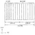
도 3은 3GPP LTE(-A) 시스템에서 사용되는 하향링크 서브프레임 구조를 예시한 것이다.FIG. 3 illustrates a downlink subframe structure used in a 3GPP LTE (-A) system.
DL 서브프레임은 시간 도메인에서 제어영역과 데이터영역으로 구분된다. 도 3을 참조하면, 서브프레임의 첫 번째 슬롯에서 앞부분에 위치한 최대 3(혹은 4)개의 OFDM 심볼은 제어 채널이 할당되는 제어영역(control region)에 대응한다. 이하, DL 서브프레임에서 PDCCH 전송에 이용가능한 자원영역을 PDCCH 영역이라 칭한다. 제어영역으로 사용되는 OFDM 심볼(들)이 아닌 남은 OFDM 심볼들은 PDSCH(Physical Downlink Shared Channel)가 할당되는 데이터영역(data region)에 해당한다. 이하, DL 서브프레임에서 PDSCH 전송에 이용가능한 자원영역을 PDSCH 영역이라 칭한다. 3GPP LTE에서 사용되는 DL 제어 채널의 예는 PCFICH(Physical Control Format Indicator Channel), PDCCH(Physical Downlink Control Channel), PHICH(Physical hybrid ARQ indicator Channel) 등을 포함한다. PCFICH는 서브프레임의 첫 번째 OFDM 심볼에서 전송되고 서브프레임 내에서 제어 채널의 전송에 사용되는 OFDM 심볼의 개수에 관한 정보를 나른다. PHICH는 UL 전송의 응답으로 HARQ ACK/NACK(acknowledgment/negative-acknowledgment) 신호를 나른다.The DL subframe is divided into a control domain and a data domain in the time domain. Referring to FIG. 3, a maximum of 3 (or 4) OFDM symbols located at a first position in a first slot of a subframe corresponds to a control region to which a control channel is allocated. Hereinafter, a resource region available for PDCCH transmission in a DL subframe is referred to as a PDCCH region. The remaining OFDM symbols other than the OFDM symbol (s) used as a control region correspond to a data region to which PDSCH (Physical Downlink Shared Channel) is allocated. Hereinafter, a resource region usable for PDSCH transmission in a DL subframe is referred to as a PDSCH region. Examples of the DL control channel used in the 3GPP LTE include a physical control format indicator channel (PCFICH), a physical downlink control channel (PDCCH), a physical hybrid ARQ indicator channel (PHICH), and the like. The PCFICH carries information about the number of OFDM symbols transmitted in the first OFDM symbol of the subframe and used for transmission of the control channel in the subframe. The PHICH carries an HARQ ACK / NACK (acknowledgment / negative-acknowledgment) signal in response to the UL transmission.
PDCCH를 통해 전송되는 제어 정보를 DCI(Downlink Control Information)라고 지칭한다. DCI는 UE 또는 UE 그룹을 위한 자원 할당 정보 및 다른 제어 정보를 포함한다. 예를 들어, DCI는 DL 공유 채널(downlink shared channel, DL-SCH)의 전송 포맷 및 자원 할당 정보, UL 공유 채널(uplink shared channel, UL-SCH)의 전송 포맷 및 자원 할당 정보, 페이징 채널(paging channel, PCH) 상의 페이징 정보, DL-SCH 상의 시스템 정보, PDSCH 상에서 전송되는 랜덤 접속 응답과 같은 상위-계층 제어 메시지의 자원 할당 정보, UE 그룹 내의 개별 UE들에 대한 Tx 파워 제어 명령 세트, Tx 파워 제어 명령, VoIP(Voice over IP)의 활성화 지시 정보 등을 포함한다. 일 PDCCH가 나르는 DCI는 DCI 포맷에 따라서 그 크기와 용도가 다르며, 부호화율에 따라 그 크기가 달라질 수 있다.The control information transmitted through the PDCCH is referred to as DCI (Downlink Control Information). The DCI includes resource allocation information and other control information for the UE or UE group. For example, the DCI may include a transport format and resource allocation information of a downlink shared channel (DL-SCH), a transport format and resource allocation information of an uplink shared channel (UL-SCH), a paging channel layer control message such as random access response transmitted on the PDSCH, Tx power control instruction set for individual UEs in the UE group, Tx power Control instruction, activation instruction information of VoIP (Voice over IP), and the like. The DCI carried by one PDCCH differs in size and usage according to the DCI format, and its size may vary according to the coding rate.
복수의 PDCCH가 DL 서브프레임의 PDCCH 영역 내에서 전송될 수 있다. UE는 복수의 PDCCH를 모니터링 할 수 있다. BS는 UE에게 전송될 DCI에 따라 DCI 포맷을 결정하고, DCI에 CRC(cyclic redundancy check)를 부가한다. CRC는 PDCCH의 소유자 또는 사용 목적에 따라 식별자(예, RNTI(radio network temporary identifier))로 마스킹(또는 스크램블)된다. 예를 들어, PDCCH가 특정 UE을 위한 것일 경우, 해당 UE의 식별자(예, cell-RNTI (C-RNTI))가 CRC에 마스킹 될 수 있다. PDCCH가 페이징 메시지를 위한 것일 경우, 페이징 식별자(예, paging-RNTI (P-RNTI))가 CRC에 마스킹 될 수 있다. PDCCH가 시스템 정보(보다 구체적으로, 시스템 정보 블록(system information block, SIB))를 위한 것일 경우, SI-RNTI(system information RNTI)가 CRC에 마스킹 될 수 있다. PDCCH가 랜덤 접속 응답을 위한 것일 경우, RA-RNTI(random access-RNTI)가 CRC에 마스킹 될 수 있다. CRC 마스킹(또는 스크램블)은 예를 들어 비트 레벨에서 CRC와 RNTI를 XOR 연산하는 것을 포함한다.A plurality of PDCCHs may be transmitted within the PDCCH region of the DL subframe. The UE may monitor a plurality of PDCCHs. The BS determines the DCI format according to the DCI to be transmitted to the UE, and adds a cyclic redundancy check (CRC) to the DCI. The CRC is masked (or scrambled) by an identifier (e.g., a radio network temporary identifier (RNTI)) according to the owner of the PDCCH or the purpose of use. For example, if the PDCCH is for a specific UE, the identifier (e.g., cell-RNTI (C-RNTI)) of the UE may be masked in the CRC. If the PDCCH is for a paging message, the paging identifier (e.g., paging-RNTI (P-RNTI)) may be masked to the CRC. If the PDCCH is for system information (more specifically, a system information block (SIB)), the system information RNTI (SI-RNTI) may be masked to the CRC. If the PDCCH is for a random access response, a random access-RNTI (RA-RNTI) may be masked in the CRC. CRC masking (or scrambling) includes, for example, XORing CRC and RNTI at the bit level.
PDCCH는 하나 또는 복수의 연속된 제어 채널 요소(control channel element, CCE)들의 집성(aggregation) 상에서 전송된다. CCE는 PDCCH에 무선 채널 상태에 기초한 코딩 레이트를 제공하는데 사용되는 논리적 할당 유닛이다. CCE는 복수의 자원 요소 그룹(resource element group, REG)에 대응한다. 예를 들어, 하나의 CCE는 9개의 REG에 대응되고 하나의 REG는 4개의 RE에 대응한다. 4개의 QPSK 심볼이 각각의 REG에 맵핑된다. 참조신호(RS)에 의해 점유된 자원요소(RE)는 REG에 포함되지 않는다. 따라서, 주어진 OFDM 심볼 내에서 REG의 개수는 RS의 존재 여부에 따라 달라진다. REG 개념은 다른 DL 제어채널(즉, PCFICH 및 PHICH)에도 사용된다. DCI 포맷 및 DCI 비트의 개수는 CCE의 개수에 따라 결정된다.The PDCCH is transmitted on an aggregation of one or more contiguous control channel elements (CCEs). The CCE is a logical allocation unit used to provide the PDCCH with a coding rate based on radio channel conditions. The CCE corresponds to a plurality of resource element groups (REG). For example, one CCE corresponds to nine REGs, and one REG corresponds to four REs. Four QPSK symbols are mapped to each REG. The resource element RE occupied by the reference signal RS is not included in the REG. Therefore, the number of REGs in a given OFDM symbol depends on the presence or absence of RS. The REG concept is also used for other DL control channels (i.e., PCFICH and PHICH). The number of DCI formats and DCI bits is determined by the number of CCEs.
CCE들은 번호가 매겨져 연속적으로 사용되고, 복호 프로세스를 간단히 하기 위해, n개 CCE들로 구성된 포맷을 가지는 PDCCH는 n의 배수에 해당하는 번호를 가지는 CCE에서만 시작될 수 있다. 특정 PDCCH의 전송에 사용되는 CCE의 개수, 다시 말해, CCE 집성 레벨은 채널 상태에 따라 BS에 의해 결정된다. 예를 들어, 좋은 DL 채널을 가지는 UE(예, BS에 인접함)를 위한 PDCCH의 경우 하나의 CCE로도 충분할 수 있다. 그러나, 열악한 채널을 가지는 UE(예, 셀 경계에 근처에 존재)를 위한 PDCCH의 경우 충분한 로버스트(robustness)를 얻기 위해서는 8개의 CCE가 요구될 수 있다.CCEs are numbered consecutively, and in order to simplify the decoding process, a PDCCH having a format composed of n CCEs can be started only in a CCE having a number corresponding to a multiple of n. The number of CCEs used for transmission of a particular PDCCH, i. E., The CCE aggregation level, is determined by the BS according to the channel conditions. For example, in the case of a PDCCH for a UE with a good DL channel (e.g., adjacent to the BS), one CCE may be sufficient. However, for a PDCCH for a UE with a poor channel (e.g., near the cell boundary), eight CCEs may be required to obtain sufficient robustness.
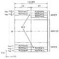
도 4는 3GPP LTE(-A) 시스템에서 사용되는 상향링크 서브프레임 구조의 일례를 나타낸 것이다.FIG. 4 shows an example of a UL subframe structure used in the 3GPP LTE (-A) system.
도 4를 참조하면, UL 서브프레임은 주파수 도메인에서 제어영역과 데이터영역으로 구분될 수 있다. 하나 또는 여러 PUCCH(physical uplink control channel)가 UCI(uplink control information)를 나르기 위해, 상기 제어영역에 할당될 수 있다. 하나 또는 여러 PUSCH(physical uplink shared channel)가 사용자 데이터를 나르기 위해, UL 서브프레임의 데이터영역에 할당될 수 있다. UL 서브프레임 내 제어영역과 데이터영역은 PUCCH 영역과 PUSCH 영역으로 각각 불리기도 한다. 상기 데이터영역에는 사운딩 참조신호(sounding reference signal, SRS)가 할당될 수도 있다. SRS는 시간 도메인에서는 UL 서브프레임의 가장 마지막에 위치하는 OFDM 심볼, 주파수 도메인에서는 상기 UL 서브프레임의 데이터 전송 대역, 즉, 데이터영역 상에서 전송된다. 동일한 서브프레임의 마지막 OFDM 심볼에서 전송/수신되는 여러 UE들의 SRS들은 주파수 위치/시퀀스에 따라 구분이 가능하다.Referring to FIG. 4, the UL subframe may be divided into a control domain and a data domain in the frequency domain. One or several physical uplink control channels (PUCCHs) may be assigned to the control region to carry UCI (uplink control information). One or several physical uplink shared channels (PUSCHs) may be allocated to the data area of the UL subframe to carry user data. The control area and the data area in the UL subframe are also referred to as a PUCCH area and a PUSCH area, respectively. A sounding reference signal (SRS) may be allocated to the data area. The SRS is transmitted on the last OFDM symbol in the UL subframe in the time domain and on the data transmission band, i.e., the data area, in the UL subframe in the frequency domain. SRSs of UEs transmitted / received in the last OFDM symbol of the same subframe can be classified according to the frequency location / sequence.
UE가 UL 전송에 SC-FDMA 방식을 채택하는 경우, 단일 반송파 특성을 유지하기 위해, 3GPP LTE 릴리즈(release) 8 혹은 릴리즈 9 시스템에서는, 일 반송파 상에서는 PUCCH와 PUSCH를 동시에 전송할 수 없다. 3GPP LTE 릴리즈 10 시스템에서는, PUCCH와 PUSCH의 동시 전송 지원 여부가 상위 계층에서 지시될 수 있다.When the UE adopts the SC-FDMA scheme for the UL transmission, in the 3GPP LTE Release 8 or Release 9 system, the PUCCH and the PUSCH can not be simultaneously transmitted on a single carrier in order to maintain the single carrier characteristic. In the
UL 서브프레임에서는 DC(Direct Current) 부반송파를 기준으로 거리가 먼 부반송파들이 제어영역으로 활용된다. 다시 말해, UL 전송 대역폭의 양쪽 끝부분에 위치하는 부반송파들이 상향링크 제어정보의 전송에 할당된다. DC 부반송파는 신호 전송에 사용되지 않고 남겨지는 성분으로, 주파수 상향변환 과정에서 반송파 주파수 f0로 맵핑된다. 일 UE에 대한 PUCCH는 일 서브프레임에서, 일 반송파 주파수에서 동작하는 자원들에 속한 RB 쌍에 할당되며, 상기 RB 쌍에 속한 RB들은 두 개의 슬롯에서 각각 다른 부반송파를 점유한다. 이와 같이 할당되는 PUCCH를, PUCCH에 할당된 RB 쌍이 슬롯 경계에서 주파수 호핑된다고 표현한다. 다만, 주파수 호핑이 적용되지 않는 경우에는, RB 쌍이 동일한 부반송파를 점유한다.In the UL subframe, subcarriers far away from the direct current (DC) subcarrier are used as a control region. In other words, subcarriers located at both ends of the UL transmission bandwidth are allocated for transmission of uplink control information. The DC subcarrier is a component that is left unused for signal transmission and is mapped to the carrier frequency f0 in the frequency up conversion process. In one subframe, a PUCCH for one UE is allocated to an RB pair belonging to resources operating at a single carrier frequency, and RBs belonging to the RB pair occupy different subcarriers in two slots. The PUCCH allocated as described above is expressed as the RB pair allocated to the PUCCH is frequency-hopped at the slot boundary. However, when frequency hopping is not applied, the RB pairs occupy the same subcarrier.
일 PUCCH가 나르는 UCI는 PUCCH 포맷에 따라서 그 크기와 용도가 다르며, 부호화율에 따라 그 크기가 달라질 수 있다. 예를 들어, 다음과 같은 PUCCH 포맷이 정의될 수 있다.A UCI carried by one PUCCH differs in size and usage according to the PUCCH format, and its size may vary according to the coding rate. For example, the following PUCCH format can be defined.

표 2를 참조하면, PUCCH 포맷 1 계열과 PUCCH 포맷 3 계열은 주로 ACK/NACK 정보를 전송하는 데 사용되며, PUCCH 포맷 2 계열은 주로 CQI(channel quality indicator)/PMI(precoding matrix index)/RI(rank index) 등의 채널상태정보를 나르는 데 사용된다.Referring to Table 2, the
CSICSI 보고 report
3GPP LTE(-A) 시스템에서는, 사용자 기기(UE)가 채널상태정보(CSI)를 기지국(BS)으로 보고하도록 정의되었으며, 채널상태정보(CSI)라 함은 UE와 안테나 포트 사이에 형성되는 무선 채널(혹은 링크라고도 함)의 품질을 나타낼 수 있는 정보를 통칭한다. 예를 들어, 랭크 지시자(rank indicator, RI), 프리코딩행렬 지시자(precoding matrix indicator, PMI), 채널품질지시자(channel quality indicator, CQI) 등이 이에 해당한다. 여기서, RI는 채널의 랭크(rank) 정보를 나타내며, 이는 UE가 동일 시간-주파수 자원을 통해 수신하는 스트림의 개수를 의미한다. 이 값은 채널의 롱 텀 페이딩(fading)에 의해 종속되어 결정되므로, PMI, CQI보다 보통 더 긴 주기를 가지고 UE에서 BS로 피드백된다. PMI는 채널 공간 특성을 반영한 값으로 SINR 등의 메트릭(metric)을 기준으로 UE가 선호하는 프리코딩 인덱스를 나타낸다. CQI는 채널의 세기를 나타내는 값으로 일반적으로 BS가 PMI를 이용했을 때 얻을 수 있는 수신 SINR을 의미한다.In the 3GPP LTE (-A) system, a user equipment (UE) is defined to report channel state information (CSI) to a base station (BS), and channel state information (CSI) Refers to information that can indicate the quality of a channel (or a link). For example, a rank indicator (RI), a precoding matrix indicator (PMI), a channel quality indicator (CQI), and the like. Here, RI denotes rank information of a channel, which means the number of streams that the UE receives through the same time-frequency resource. Since this value is determined by being dependent on the long term fading of the channel, it is fed back from the UE to the BS with a period longer than the PMI, CQI, usually longer. The PMI is a value reflecting the channel space characteristic and indicates a preferred precoding index of the UE based on a metric such as SINR. The CQI is a value representing the strength of a channel, and generally refers to a reception SINR that can be obtained when the BS uses the PMI.
상기 무선 채널의 측정에 기반하여, UE는 현재 채널 상태 하에서 상기 BS에 의해 사용된다면 최적 또는 최고의 전송 레이트를 도출할 수 있는 선호되는 PMI 및 RI를 계산하고, 계산된 PMI 및 RI를 상기 BS로 피드백한다. 여기서, CQI는 상기 피드백된 PMI/RI에 대한 수용가능한 패킷 에러율(packet error probability)을 제공하는 변조 및 코딩 방식(modulation and coding scheme)을 지칭한다.Based on the measurement of the radio channel, the UE computes the preferred PMI and RI that can derive an optimal or maximum transmission rate if used by the BS under the current channel conditions, and feeds the calculated PMI and RI back to the BS do. Here, the CQI refers to a modulation and coding scheme that provides an acceptable packet error probability for the feedback PMI / RI.
한편, 더 정밀한 MU-MIMO와 명시적인 CoMP 동작들을 포함하도록 기대되는LTE-A 시스템에서, 현재의 CSI 피드백은 LTE에서 정의되었으며 따라서 저러한 새롭게 도입될 동작들을 충분하게 지원하지 못한다. CSI 피드백 정확도에 대한 요구사항이 충분한 MU-MIMO 또는 CoMP 스루풋(throughput) 이득을 얻기 위해 점점 까다로워짐에 따라, PMI가 롱 텀(long term)/광대역(wideband) PMI (W1) 그리고 숏 텀(short term)/서브밴드(subband) PMI (W2), 두 가지로 구성되도록 합의되었다. 다시 말해서, 최종 PMI는 W1과 W2의 함수로서 표현된다. 예컨대, 최종 PMI W는 다음과 같이 정의될 수 있다: W=W1*W2 or W=W2*W1. 따라서, LTE-A에서 CSI는 RI, W1, W2 및 CQI로 구성될 것이다.On the other hand, in LTE-A systems that are expected to include more precise MU-MIMO and explicit CoMP operations, the current CSI feedback is defined in LTE and therefore does not adequately support such newly introduced operations. As the requirements for CSI feedback accuracy become increasingly difficult to obtain sufficient MU-MIMO or CoMP throughput gains, the PMI is able to achieve a long term / wideband PMI (W1) and short (short) term / subband PMI (W2). In other words, the final PMI is expressed as a function of W1 and W2. For example, the final PMI W may be defined as: W = W1 * W2 or W = W2 * W1. Therefore, in LTE-A, CSI will be composed of RI, W1, W2 and CQI.
3GPP LTE(-A)시스템에서 CSI 전송을 위해 사용되는 상향링크 채널은 다음 표 3과 같다.Table 3 shows the uplink channels used for CSI transmission in the 3GPP LTE (-A) system.

표 3을 참조하면, CSI는 상위 계층에서 정한 주기로 물리상향링크 제어채널(Physical Uplink Control Channel, PUCCH)을 이용하여 전송될 수 있고, 스케줄러의 필요에 따라 비주기적으로 물리상향링크 공유채널(Physical Uplink Shared Channel, PUSCH)을 이용하여 전송될 수 있다. CSI가 PUSCH로 전송되는 경우는 주파수 선택적인 스케줄링 방식 및 비주기적 CSI 전송인 경우에만 가능하다. 이하에서는 스케줄링 방식 및 주기성에 따른 CSI 전송 방식에 대해서 설명한다.Referring to Table 3, the CSI can be transmitted using a physical uplink control channel (PUCCH) at a predetermined period in an upper layer, and can be periodically transmitted to a physical uplink shared channel Shared Channel, PUSCH). When the CSI is transmitted on the PUSCH, it is possible only in a frequency selective scheduling scheme and an aperiodic CSI transmission. Hereinafter, a CSI transmission scheme according to a scheduling scheme and periodicity will be described.
1) CSI 전송 요청 제어 신호(CSI request) 수신 후 PUSCH를 통한 CQI/PMI/RI 전송1) CQI / PMI / RI transmission through PUSCH after receiving CSI transmission request control signal (CSI request)
PDCCH 신호로 전송되는 PUSCH 스케줄링 제어신호(UL Grant)에 CSI를 전송하도록 요청하는 제어 신호가 포함될 수 있다. 다음 표 4는 PUSCH를 통해 CQI, PMI, RI를 전송할 때의 UE의 모드를 나타낸다.A control signal requesting transmission of CSI to a PUSCH scheduling control signal (UL Grant) transmitted in a PDCCH signal may be included. Table 4 below shows modes of the UE when CQI, PMI, and RI are transmitted through the PUSCH.

표 4의 전송 모드는 상위 레이어에서 선택되며, CQI/PMI/RI는 모두 같은 PUSCH 서브프레임에서 전송된다. 이하에서는, 각 모드에 따른 UE의 상향링크 전송 방법에 대해서 설명한다.The transmission mode in Table 4 is selected in the upper layer, and CQI / PMI / RI are all transmitted in the same PUSCH subframe. Hereinafter, an uplink transmission method of the UE according to each mode will be described.
모드 1-2(Mode 1-2)는 각각의 서브밴드에 대해서 데이터가 서브밴드만을 통해서 전송된다는 가정하에 프리코딩 행렬을 선택하는 경우를 나타낸다. UE는 시스템 대역 또는 상위 레이어에서 지정한 대역(set S) 전체에 대해서 선택한 프리코딩 행렬을 가정하여 CQI를 생성한다. 모드 1-2에서 UE는 CQI와 각 서브밴드의 PMI 값을 전송할 수 있다. 이때, 각 서브밴드의 크기는 시스템 대역의 크기에 따라 달라질 수 있다.Mode 1-2 (Mode 1-2) shows a case where a precoding matrix is selected on the assumption that data is transmitted only through subbands for each subband. The UE generates the CQI by assuming a selected precoding matrix for the entire band (set S) designated by the system band or an upper layer. In Mode 1-2, the UE can transmit the CQI and the PMI value of each subband. At this time, the size of each subband may vary depending on the size of the system band.
모드 2-0(Mode 2-0)인 UE는 시스템 대역 또는 상위 레이어에서 지정한 지정 대역(set S)에 대해서 선호하는 M개의 서브밴드를 선택할 수 있다. UE는 선택한 M개의 서브밴드에 대해서 데이터를 전송한다는 가정하에 하나의 CQI 값을 생성할 수 있다. UE는 추가로 시스템 대역 또는 set S에 대해서 하나의 CQI (wideband CQI) 값을 보고하는 것이 바람직하다. UE는 선택한 M개의 서브밴드들에 대해서 다수 개의 코드워드가 있을 경우, 각 코드워드에 대한 CQI 값을 차분 형식으로 정의한다.The UE in mode 2-0 (Mode 2-0) can select M subbands preferred for the designated band (set S) designated by the system band or the upper layer. The UE may generate one CQI value on the assumption that it transmits data for the selected M subbands. The UE further preferably reports one CQI (wideband CQI) value for the system band or set S. When there are a plurality of codewords for the selected M subbands, the UE defines a CQI value for each codeword in a differential format.
이때, 차분 CQI 값은 선택한 M개의 서브밴드에 대한 CQI 값에 해당하는 인덱스와 광대역 CQI(WB-CQI: Wideband CQI) 인덱스의 차이값으로 결정된다.At this time, the difference CQI value is determined by a difference between the index corresponding to the C sub-band for the selected M subbands and the wideband CQI (Wideband CQI) index.
모드 2-0인 UE는 선택한 M개의 서브밴드의 위치에 대한 정보, 선택한 M개의 서브밴드들에 대한 하나의 CQI 값 및 전 대역 또는 지정 대역(set S)에 대해서 생성한 CQI 값을 BS로 전송할 수 있다. 이때, 서브밴드의 크기 및 M값은 시스템 대역의 크기에 따라 달라질 수 있다.In the mode 2-0, the UE transmits information on the positions of the selected M subbands, one CQI value for the selected M subbands, and the CQI value generated for the entire band or the designated band (set S) to the BS . At this time, the size and the M value of the subband can be changed according to the size of the system band.
모드 2-2(Mode 2-2)인 UE는 M개의 선호하는 서브밴드를 통하여 데이터를 전송한다는 가정하에, M개의 선호 서브밴드의 위치와 M개의 선호 서브밴드에 대한 단일 프리코딩 행렬을 동시에 선택할 수 있다. 이때, M개의 선호 서브밴드에 대한CQI 값은 코드워드마다 정의된다. 또한, UE는 추가로 시스템 대역 또는 지정 대역(set S)에 대해서 광대역 CQI(wideband CQI) 값을 생성한다.A mode 2-2 (Mode 2-2) UE selects a single precoding matrix for M preferred subbands and M preferred subbands at the same time, assuming that the data is transmitted through M preferred subbands . At this time, the CQI values for the M preferred subbands are defined for each codeword. In addition, the UE further generates a wideband CQI value for the system band or the designated band (set S).
모드 2-2인 UE는 M개의 선호하는 서브밴드의 위치에 대한 정보, 선택된 M개의 서브밴드들에 대한 하나의 CQI 값, M개의 선호하는 서브밴드에 대한 단일 PMI, 광대역 PMI, 광대역 CQI 값을 BS로 전송할 수 있다. 이때, 서브밴드의 크기 및 M 값은 시스템 대역의 크기에 따라 달라질 수 있다.The UE in mode 2-2 receives information on the location of M preferred subbands, one CQI value for selected M subbands, a single PMI for M preferred subbands, a wideband PMI, and a wideband CQI value BS. At this time, the size and the M value of the subband can be changed according to the size of the system band.
모드 3-0(Mode 3-0)인 UE는 광대역 CQI 값을 생성한다. UE는 각 서브밴드를 통해서 데이터를 전송한다는 가정하에 각 서브밴드에 대한 CQI 값을 생성한다. 이때, RI > 1이더라도 CQI 값은 첫 번째 코드워드에 대한 CQI 값만을 나타낸다.The UE in mode 3-0 (Mode 3-0) generates a wideband CQI value. The UE generates a CQI value for each subband on the assumption that data is transmitted through each subband. At this time, even if RI> 1, the CQI value represents only the CQI value for the first codeword.
모드 3-1(Mode 3-1)인 UE는 시스템 대역 또는 지정대역(set S)에 대해서 단일 프리코딩 행렬(precoding matrix)을 생성한다. UE는 각 서브밴드에 대해서 앞서 생성한 단일 프리코딩 행렬을 가정하고, 코드워드 별로 서브밴드 CQI를 생성한다. 또한, UE는 단일 프리코딩 행렬을 가정하고 광대역 CQI를 생성할 수 있다. 각 서브밴드의 CQI 값은 차분 형식으로 표현될 수 있다. 서브밴드 CQI 값은 서브밴드 CQI 인덱스와 광대역 CQI 인덱스의 차이값으로 계산된다. 이때, 서브밴드의 크기는 시스템 대역의 크기에 따라 달라질 수 있다.A UE in mode 3-1 (Mode 3-1) generates a single precoding matrix for a system band or a designated band (set S). The UE assumes a single precoding matrix generated for each subband, and generates a subband CQI for each codeword. In addition, the UE may assume a single precoding matrix and generate a wideband CQI. The CQI value of each subband can be expressed in a differential format. The subband CQI value is calculated as the difference between the subband CQI index and the wideband CQI index. At this time, the size of the sub-band may vary depending on the size of the system band.
2) PUCCH를 통한 주기적인 CQI/PMI/RI 전송2) Periodic CQI / PMI / RI transmission through PUCCH
UE는 CSI(e.g. CQI/PMI/RI 정보)를 PUCCH를 통해 BS에 주기적으로 전송할 수 있다. 만약, UE가 사용자 데이터를 전송하라는 제어신호를 수신하였을 경우에는, UE는 PUCCH를 통하여 CQI를 전송할 수 있다. 제어신호가 PUSCH를 통하여 전송되더라도 CQI/PMI/RI는 다음 표 5에서 정의된 모드들 중 하나의 방식에 의해 전송될 수 있다.The UE may periodically transmit CSI (e.g., CQI / PMI / RI information) to the BS via the PUCCH. If the UE receives a control signal to transmit user data, the UE may transmit the CQI via the PUCCH. The CQI / PMI / RI can be transmitted by one of the modes defined in Table 5, even if the control signal is transmitted via the PUSCH.

UE는 표 5와 같은 전송 모드를 가질 수 있다. 표 5를 참조하면, 모드 2-0(Mode 2-0) 및 모드 2-1(Mode 2-1)의 경우, 대역폭 파트(BP: Bandwidth Part)는 주파수 영역에서 연속적으로 위치한 서브밴드들의 집합이며 시스템 대역 또는 지정대역(set S)를 모두 커버할 수 있다. 표 5에서 각 서브밴드의 크기, BP의 크기 및 BP의 개수는 시스템 대역의 크기에 따라 달라질 수 있다. 또한, UE는 시스템 대역 또는 지정대역(set S)을 커버할 수 있도록 BP 별로 CQI를 주파수 영역에서 오름차순으로 전송한다.The UE may have a transmission mode as shown in Table 5. Referring to Table 5, in the case of Mode 2-0 (Mode 2-0) and Mode 2-1 (Mode 2-1), a Bandwidth Part (BP) is a set of subbands located consecutively in the frequency domain System band or the designated band (set S). In Table 5, the size of each subband, the size of BP, and the number of BPs may vary depending on the size of the system band. Also, the UE transmits the CQIs in the frequency domain in the ascending order so as to cover the system band or the designated band (set S).
CQI/PMI/RI의 전송 조합에 따라, UE는 다음과 같은 4개의 전송 타입을 가질 수 있다.Depending on the combination of CQI / PMI / RI transmissions, the UE may have four transmission types:
i) 제 1 타입(Type 1): 모드 2-0(Mode 2-0), 모드 2-1(Mode 2-1)의 서브밴드 CQI(SB-CQI)를 전송한다.i) Type 1: Transmit the subband CQI (SB-CQI) of Mode 2-0 (Mode 2-0) and Mode 2-1 (Mode 2-1).
ii) 제 2 타입(Type 2): 광대역 CQI 및 PMI(WB-CQI/PMI)를 전송한다.ii) Type 2 (Type 2): Broadband CQI and PMI (WB-CQI / PMI) are transmitted.
iii) 제 3 타입(Type 3): RI를 전송한다.iii) Type 3: Type RI is transmitted.
iv) 제 4 타입(Type 4): 광대역 CQI를 전송한다.iv) Type 4 (Type 4): Broadband CQI is transmitted.
UE가 RI와 광대역 CQI/PMI를 전송하는 경우, CQI/PMI는 서로 다른 주기와 오프셋을 가지는 서브프레임에 전송된다. 또한, RI와 광대역 CQI/PMI가 같은 서브프레임에 전송되어야 하는 경우에는 CQI/PMI는 전송되지 않는다.When the UE transmits a wideband CQI / PMI to the RI, the CQI / PMI is transmitted in a subframe having different periods and offsets. In addition, when RI and the wideband CQI / PMI are to be transmitted in the same subframe, the CQI / PMI is not transmitted.
표 5에서 광대역 CQI/PMI 및 서브밴드 CQI의 전송 주기는 P이고, 다음의 특징을 갖는다.In Table 5, the transmission period of the wideband CQI / PMI and the subband CQI is P and has the following characteristics.
- 광대역 CQI/PMI는 H*P의 주기를 갖는다. 이 때, H=J*K+1이고, J는 BP의 개수, K는 BP의 전체 주기의 횟수이다. 즉, UE는 {0, H, 2H, ...}에 전송한다.The broadband CQI / PMI has a period of H * P. At this time, H = J * K + 1, J is the number of BPs, and K is the total number of BP cycles. That is, the UE transmits to {0, H, 2H, ...}.
- 광대역 CQI/PMI를 전송하는 시점이외의 J*K 시점에서는 CQI를 전송한다.- The CQI is transmitted at J * K points other than the time of transmitting the broadband CQI / PMI.
표 5에서 RI의 전송 주기는 광대역 CQI/PMI 주기의 M 배이며, 다음의 특징을 갖는다.In Table 5, the transmission period of RI is M times the broadband CQI / PMI period and has the following characteristics.
- RI와 광대역 CQI/PMI의 오프셋은 O이고, RI와 광대역 CQI/PMI가 동일한 서브프레임에 전송되는 경우 광대역 CQI/PMI는 전송되지 않는다.- The offset of RI and broadband CQI / PMI is O, and broadband CQI / PMI is not transmitted when RI and broadband CQI / PMI are transmitted in the same subframe.
표 4에서 개시된 파라미터 P, H, K 및 O는 모두 UE의 상위 레이어에서 결정하여 UE의 물리계층으로 시그널링된다.The parameters P, H, K, and O disclosed in Table 4 are all determined at the upper layer of the UE and signaled to the physical layer of the UE.
이하에서는 표 5를 참고하여, UE의 모드에 다른 피드백 동작에 대해서 설명한다. UE가 모드 1-0(Mode 1-0)이고 RI를 BS에 전송하는 경우, UE는 시스템 대역 또는 지정 대역(set S)에 대하여 RI를 생성하고, RI를 전송하기 위한 제 3 타입 리포트를 BS에 전송한다. UE가 CQI를 전송하는 경우, 광대역 CQI를 전송한다.Hereinafter, with reference to Table 5, a description will be given of a feedback operation different from the mode of the UE. When the UE is in mode 1 - 0 (Mode 1 - 0) and transmits an RI to the BS, the UE generates RI for the system band or the designated band (set S) and sends a third type report for transmitting the RI to the BS Lt; / RTI > When the UE transmits the CQI, it transmits the wideband CQI.
UE가 모드 1-1(Mode 1-1)이고 RI를 전송하는 경우, 시스템 대역 또는 지정 대역(set S)에 대하여 RI를 생성하고, RI를 전송하기 위한 제 3 타입 리포트를 BS에 전송한다. UE가 CQI/PMI를 전송하는 경우, 가장 최근에 전송한 RI를 고려하여 단일 프리코딩 행렬을 선정한다. 즉, UE는 광대역 CQI, 단일 프리코딩 행렬, 차분 광대역 CQI로 구성된 제 2 타입 리포트를 BS로 전송한다.When the UE is in Mode 1-1 (Mode 1-1) and transmits an RI, it generates an RI for the system band or the designated band (set S), and transmits a third type report for transmitting the RI to the BS. When the UE transmits the CQI / PMI, a single precoding matrix is selected in consideration of the most recently transmitted RI. That is, the UE transmits a second type report composed of a wideband CQI, a single precoding matrix, and a differential wideband CQI to the BS.
UE가 모드 2-0(Mode 2-0)이고 RI를 전송하는 경우, 시스템 대역 또는 지정 대역(set S)에 대하여 RI를 생성하고, RI를 전송하기 위한 제 3 타입 리포트를 BS에 전송한다. UE가 광대역 CQI를 전송하는 경우, 가장 최근에 전송한 RI를 가정하여 광대역 CQI를 생성하고 제 4 타입 리포트를 BS로 전송한다. UE는 선택한 서브밴드에 대한 CQI를 전송하는 경우, UE는 N개의 서브밴드로 구성된 J개의 BP에 대해서 가장 선호하는 서브밴드를 선택하여, 제 1 타입 리포트를 BS로 전송한다. 제 1 타입 리포트는 BP에 따라서 1개 이상의 서브프레임을 통해 전송될 수 있다.When the UE is in mode 2-0 (Mode 2-0) and transmits an RI, it generates an RI for the system band or the designated band (set S), and transmits a third type report for transmitting the RI to the BS. When the UE transmits a wideband CQI, it generates a wideband CQI based on the most recently transmitted RI and transmits a fourth type report to the BS. When the UE transmits the CQI for the selected subband, the UE selects the most preferred subband for the J BPs composed of N subbands, and transmits the first type report to the BS. The first type report can be transmitted through one or more subframes according to the BP.
UE가 모드 2-1(Mode 2-1)이고 RI를 전송하는 경우, 시스템 대역 또는 지정대역(set S)에 대하여 RI를 생성하고, RI를 전송하기 위한 제 3 타입 리포트를 BS에 전송한다. UE가 광대역 CQI를 BS에 전송하는 경우, 가장 최근에 전송한 RI를 고려하여 광대역 CQI를 생성하고 제 4 타입 리포트를 BS에 전송한다. 선택된 서브밴드들에 대한 CQI가 전송되는 경우, UE는 Nj개로 구성된 J개의 BP에 대해서, 가장 최근에 전송한 PMI/RI를 고려하여 BP 내에 선택된 서브밴드들에 대한 단일 CQI 값과, RI가 1보다 큰 경우에는 가장 최근에 전송한 RI와 선택된 서브밴드에 단일 프리코딩 행렬을 사용한 것을 가정하여 코드워드의 CQI 차이를 생성하여 제 1 타입 리포트를 BS에 전송한다.When the UE is in Mode 2-1 (Mode 2-1) and transmits RI, it generates an RI for the system band or the designated band (set S), and transmits a third type report for transmitting the RI to the BS. When the UE transmits the wideband CQI to the BS, it generates the wideband CQI considering the most recently transmitted RI and transmits the fourth type report to the BS. When the CQIs for the selected subbands are transmitted, the UE calculates a single CQI value for the subbands selected in the BP considering the most recently transmitted PMI / RI for J BPs composed of Nj, It is assumed that a single precoding matrix is used for the most recently transmitted RI and the selected subband, and a CQI difference of the codeword is generated to transmit the first type report to the BS.
앞서 설명한 BS와 UE 간의 채널상태의 추정(CSI 보고)과 더불어 간섭 신호의 완화, BS와 UE 사이에 전송된 신호의 복조 등을 위하여 다양한 참조신호(reference signal, RS)가 BS와 UE간에 전송된다. 참조신호라 함은 BS로부터 UE로 혹은 UE로부터 BS로 전송하는, BS와 UE가 서로 알고 있는 기정의된, 특별한 파형의 신호를 의미하며, 파일럿(pilot)이라고도 불린다. 3GPP LTE 릴리즈 8(이하, Rel-8)에는 CQI 피드백을 위한 채널 측정과 PDSCH(Physical Downlink Shared Channel)의 복조(demodulation)를 목적으로 셀 특정적 참조신호(cell specific reference signal, CRS)이 제안되어 있다. 그러나, 3GPP LTE 릴리즈 10(이하, Rel-10)에서부터는 Rel-8의 CRS와 별도로 Rel-10에 따라 CSI 피드백을 위한 채널상태정보 참조신호(channel state information reference signal, CSI-RS)가 제안되었다.Various reference signals (RS) are transmitted between the BS and the UE for the estimation of the channel state between the BS and the UE (CSI report) as described above, mitigation of the interference signal, demodulation of signals transmitted between the BS and the UE . Reference signal refers to a predefined signal of a particular waveform transmitted from the BS to the UE or from the UE to the BS and known to the BS and the UE and is also referred to as a pilot. In 3GPP LTE Release 8 (hereinafter referred to as Rel-8), a cell specific reference signal (CRS) has been proposed for the purpose of channel measurement for CQI feedback and demodulation of PDSCH (Physical Downlink Shared Channel) have. However, a channel state information reference signal (CSI-RS) for CSI feedback according to Rel-10 has been proposed separately from CRS of Rel-8 from 3GPP LTE Release 10 (hereinafter referred to as Rel-10) .
각각의 BS는 복수 개의 안테나 포트를 통해 UE로 채널 측정을 위한 CSI-RS를 전송하며, 각각의 UE는 그에 응답하여 CSI-RS에 기반하여 채널상태정보를 계산하여 각각의 BS로 전송할 수 있다.Each BS transmits a CSI-RS for channel measurement to a UE through a plurality of antenna ports, and each UE can calculate channel state information based on the CSI-RS in response thereto, and transmit the CSI-RS to each BS.
협력형 다중-포인트 송수신 기법(Cooperative multi - point transmission / reception techniqueCoordinatedCoordinatedMultipleMultiplePointPointtransmissiontransmission and andreceptionreception;;CoMPCoMP))
3GPP LTE-A 시스템의 개선된 시스템 성능 요구조건에 따라서, CoMP 송수신 기술(co-MIMO, 공동(collaborative) MIMO 또는 네트워크 MIMO 등으로 표현되기도 함)이 제안되고 있다. CoMP 기술은 셀-경계(cell-edge)에 위치한 UE의 성능을 증가시키고 평균 섹터 수율(throughput)을 증가시킬 수 있다.CoMP transmission and reception techniques (also referred to as co-MIMO, collaborative MIMO, or network MIMO, etc.) have been proposed according to the improved system performance requirements of the 3GPP LTE-A system. CoMP technology can increase the performance of UEs located at the cell-edge and increase the average sector throughput.
일반적으로, 주파수 재사용 인자(frequency reuse factor)가 1 인 다중-셀 환경에서, 셀-간 간섭(Inter-Cell Interference; ICI)으로 인하여 셀-경계에 위치한 UE의 성능과 평균 섹터 수율이 감소될 수 있다. 이러한 ICI를 저감하기 위하여, 기존의 LTE 시스템에서는 UE 특정 전력 제어를 통한 부분 주파수 재사용(fractional frequency reuse; FFR)과 같은 단순한 수동적인 기법을 이용하여 간섭에 의해 제한을 받은 환경에서 셀-경계에 위치한 UE가 적절한 수율 성능을 가지도록 하는 방법이 적용되었다. 그러나, 셀 당 주파수 자원 사용을 낮추기보다는, ICI를 저감하거나 ICI를 UE가 원하는 신호로 재사용하는 것이 보다 바람직할 수 있다. 위와 같은 목적을 달성하기 위하여, CoMP 전송 기법이 적용될 수 있다.Generally, in a multi-cell environment with a frequency reuse factor of 1, the performance of the UE located at the cell boundary due to Inter-Cell Interference (ICI) and the average sector yield may be reduced have. In order to reduce such ICI, in a conventional LTE system, a simple passive technique such as fractional frequency reuse (FFR) through UE specific power control is used, A method has been applied to ensure that the UE has adequate yield performance. However, rather than lowering the frequency resource usage per cell, it may be more desirable to reduce the ICI or reuse the ICI as the desired signal of the UE. In order to achieve the above object, the CoMP transmission scheme can be applied.
하향링크의 경우에 적용될 수 있는 CoMP 기법은 크게 조인트-프로세싱(joint processing; JP) 기법 및 조정 스케줄링/빔포밍(coordinated scheduling/beamforming; CS/CB) 기법으로 분류할 수 있다.CoMP techniques that can be applied in the case of downlink can be roughly classified into a joint-processing (JP) technique and a coordinated scheduling / beamforming (CS / CB) technique.
JP 기법은 CoMP 협력 단위의 각각의 포인트(기지국)에서 데이터를 이용할 수 있다. CoMP 협력 단위는 협력 전송 기법에 이용되는 기지국들의 집합을 의미하고, CoMP 집합으로도 지칭될 수 있다. JP 기법은 조인트 전송(Joint Transmission) 기법과 동적 셀 선택(Dynamic cell selection) 기법으로 분류할 수 있다.The JP technique can utilize the data at each point (base station) of the CoMP cooperating unit. The CoMP cooperating unit means a set of base stations used in the cooperative transmission scheme and may also be referred to as a CoMP aggregation. The JP method can be classified into Joint Transmission method and Dynamic cell selection method.
조인트 전송 기법은, PDSCH 가 한번에 복수개의 포인트(CoMP 협력 단위의 일부 또는 전부)로부터 전송되는 기법을 말한다. 즉, 단일 UE로 전송되는 데이터는 복수개의 전송 포인트로부터 동시에 전송될 수 있다. 조인트 전송 기법에 의하면, 코히어런트하게(coherently) 또는 넌-코히어런트하게(non-coherently) 수신 신호의 품질이 향상될 수 있고, 또한, 다른 UE에 대한 간섭을 능동적으로 소거할 수도 있다.The joint transmission scheme refers to a scheme in which the PDSCH is transmitted from a plurality of points (a part or all of CoMP cooperation units) at one time. That is, data transmitted to a single UE can be simultaneously transmitted from a plurality of transmission points. According to the joint transmission scheme, the quality of a coherently or non-coherently received signal can be improved and also actively cancel interference to other UEs.
동적 셀 선택 기법은, PDSCH가 한번에 (CoMP 협력 단위의) 하나의 포인트로부터 전송되는 기법을 말한다. 즉, 특정 시점에서 단일 UE로 전송되는 데이터는 하나의 포인트로부터 전송되고, 그 시점에 협력 단위 내의 다른 포인트는 해당 UE에 대하여 데이터 전송을 하지 않으며, 해당 UE로 데이터를 전송하는 포인트는 동적으로 선택될 수 있다.The dynamic cell selection scheme refers to a scheme in which the PDSCH is transmitted from one point (at CoMP cooperation unit) at a time. That is, data transmitted to a single UE at a specific time point is transmitted from one point, and other points in the cooperating unit at that time do not transmit data to the UE, and points for transmitting data to the UE are dynamically selected .
한편, CS/CB 기법에 의하면 CoMP 협력 단위들이 단일 UE에 대한 데이터 전송의 빔포밍을 협력적으로 수행할 수 있다. 여기서, 데이터는 서빙 셀에서만 전송되지만, 사용자 스케줄링/빔포밍은 해당 CoMP 협력 단위의 셀들의 조정에 의하여 결정될 수 있다.On the other hand, according to the CS / CB scheme, CoMP cooperation units can cooperatively perform beamforming of data transmission to a single UE. Here, the data is transmitted only in the serving cell, but the user scheduling / beamforming can be determined by adjusting the cells of the CoMP cooperation unit.
한편, 상향링크의 경우에, 협력 또는 조정(coordinated) 다중-포인트 수신은 지리적으로 떨어진 복수개의 포인트들의 조정에 의해서 전송된 신호를 수신하는 것을 의미한다. 상향링크의 경우에 적용될 수 있는 CoMP 기법은 조인트 수신(Joint Reception; JR) 및 조정 스케줄링/빔포밍(coordinated scheduling/beamforming; CS/CB)으로 분류할 수 있다.On the other hand, in the case of an uplink, cooperative or coordinated multi-point reception means receiving a signal transmitted by coordination of a plurality of points that are geographically separated. The CoMP scheme that can be applied in the case of uplink can be classified into Joint Reception (JR) and coordinated scheduling / beamforming (CS / CB).
JR 기법은 PUSCH를 통해 전송된 신호가 복수개의 수신 포인트에서 수신되는 것을 의미하고, CS/CB 기법은 PUSCH가 하나의 포인트에서만 수신되지만 사용자 스케줄링/빔포밍은 CoMP 협력 단위의 셀들의 조정에 의해 결정되는 것을 의미한다.The JR scheme means that a signal transmitted through the PUSCH is received at a plurality of reception points. In the CS / CB scheme, the PUSCH is received at only one point, but the user scheduling / beamforming is determined by adjustment of cells in CoMP cooperation unit .
도 5는 협력 다중-포인트 송수신(Coordinated Multi-Point transmission and reception; CoMP) 기법을 이용하는 무선 통신 시스템의 일 예를 간략히 도시한다. 도시된 세 개의 전송 포인트(transmission point, TP) TP1, TP2, TP3 뿐만 아니라 더 많은 수의 TP가 참여할 수 있으며, 이렇게 복수 개의 TP들로 이루어진 협력 다중 송수신 집합(set)을 CoMP 집합이라고 한다. 한편, 본 명세서에서 상기 TP는 BS 및 BS와 대응되는 용어와 상호호환 가능하게 지칭될 수 있다. CoMP 집합에 속한 TP들의 일부 또는 전부가 채널상태에 따라 UE에 대한 CoMP에 참여할 수 있다. 여기서, 상기 각각의 TP는 복수 개의 안테나 포트들을 구비할 수 있다.5 schematically illustrates an example of a wireless communication system using a Coordinated Multi-Point Transmission and Reception (CoMP) scheme. A larger number of TPs can participate in the three transmission points TP1, TP2, and TP3 shown in the figure, and a cooperative multi-transmission / reception set consisting of a plurality of TPs is called a CoMP set. On the other hand, in the present specification, the TP can be referred to as interoperable with terms corresponding to BS and BS. Some or all of the TPs belonging to the CoMP aggregation may participate in the CoMP for the UE depending on the channel conditions. Here, each of the TPs may include a plurality of antenna ports.
도 5를 참조하면, 사용자 기기(UE) 주변에 복수의 TP들이 배치되어 있고, 그 중에서 상기 UE는 제 1 TP, 제 2 TP, 제 3 TP, 좀더 상세하게는 상기 제 1, 제 2, 및 제 3 TP들의 복수의 안테나 포트들과 연결될 수 있다. 상기 UE는 이러한 복수의 안테나 포트들에 대한 채널상태정보를 네트워크에 보고할 수 있다. 즉, UE는 상기 UE가 접속한 BS에 상기 복수의 안테나 포트들에 대한 채널상태정보를 전송할 수 있다. 상기 네트워크는 상기 채널상태정보를 기반으로 상기 UE에 대한 스케줄링을 수행한다.Referring to FIG. 5, a plurality of TPs are arranged around a user equipment (UE), and the UE includes a first TP, a second TP, a third TP, and more specifically, And may be coupled to a plurality of antenna ports of the third TPs. The UE may report channel state information for the plurality of antenna ports to the network. That is, the UE may transmit channel state information for the plurality of antenna ports to the BS to which the UE is connected. The network performs scheduling for the UE based on the channel state information.
도 5는 CoMP 집합으로부터 UE가 결합 전송(joint transmission; JT) 서비스를 받는 무선 통신 시스템을 도시한다. 도 5에서, UE는 CoMP 집단에 속한 모든 TP들로부터 데이터를 수신하게 되며, 이에 따라 UE는 상기 CoMP 집단에 속한 모든 TP들에 대한 채널상태정보를 전송할 수 있다. 그러나, 도 5에 도시된 CoMP 동작에서, 각 TP로부터 UE로의 데이터 전송은 서로에게 간섭 영향을 줄 수 있다. 예컨대, TP1으로부터 UE로의 데이터 전송이 TP2로부터 UE로의 데이터 전송에 간섭을 줄 수 있다. 따라서, 도 5에 도시된 각 TP들에 대한 CSI(CSI for TP1, CSI for TP2 및 CSI for TP3)는 이러한 간섭 영향을 고려하지 않은 것이므로, CoMP 집합을 위한 CSI의 정확도가 떨어지는 문제점이 있다. 이러한 환경 하에서, CoMP 집합을 위한 새로운 CSI 계산 및 전송 방안이 요구된다.5 illustrates a wireless communication system in which a UE receives a joint transmission (JT) service from a CoMP aggregation. In FIG. 5, the UE receives data from all TPs belonging to the CoMP group, so that the UE can transmit channel status information for all TPs belonging to the CoMP group. However, in the CoMP operation shown in FIG. 5, the data transmission from each TP to the UE can affect each other with interference. For example, data transmission from TP1 to UE may interfere with data transmission from TP2 to UE. Therefore, since the CSIs (CSI for TP1, CSI for TP2 and CSI for TP3) for the TPs shown in FIG. 5 do not consider the interference effect, there is a problem that the accuracy of CSI for the CoMP aggregation is low. Under these circumstances, new CSI computation and transmission schemes for CoMP aggregation are required.
특히, CoMP 동작 중 JT 서비스의 경우엔, 여러 TP들이 특정 UE에게 동일한 데이터를 협력 전송하므로, 이론적으로 안테나가 지리적으로 분산되어 있는 MIMO 시스템으로 볼 수 있다. 다시 말하면, JT 서비스에서 MU-MIMO를 수행하는 경우에도 단일 셀 MU-MIMO와 마찬가지로 코-스케줄링(co-scheduling)되는 UE간 간섭을 피하기 위해 높은 수준의 정확도를 갖는 채널 상태 정보가 요구된다. CoMP CB의 경우에도 인접 셀이 서빙 셀에게 주는 간섭을 회피하기 위해 정교한 채널 상태 정보가 요구된다.Especially, in case of JT service during CoMP operation, since several TPs cooperatively transmit the same data to specific UEs, theoretically, it can be regarded as a MIMO system in which antennas are geographically dispersed. In other words, in the case of performing MU-MIMO in the JT service, channel status information having a high level of accuracy is required in order to avoid co-scheduling inter-UE interference like the single cell MU-MIMO. Even in CoMP CB, sophisticated channel state information is required to avoid interference caused by adjacent cells to the serving cell.
본 발명에서는 UE가 CoMP 동작을 수행하기 위해서 채널상태정보(CSI)를 계산하고 이를 BS에 보고할 때, 전송 랭크(rank)에 따라 적절하게 PMI, CQI를 계산하고 이를 보고하는 방법을 제안하고자 한다. 본 발명의 일 실시예에서는, UE가 총 N개의 전송 포인트(transmission point, TP)로 구성된 CoMP 집합에 대한 CSI를 상향링크에서 전송하고, N개의 TP가 협력하여 상기 UE로 하향링크 신호를 전송하는 방식, 즉 상기 UE와 TP들이 CoMP 동작 중 JT(joint transmission)를 수행하는 상황을 가정한다. 일반적으로, 각 TP는 별도의 CSI-RS 패턴을 가지며, UE는 N개의 CSI-RS를 통해서 CSI 보고를 위한 채널 추정을 수행할 수 있다.According to the present invention, a method for calculating and reporting a PMI and a CQI according to a transmission rank when a UE calculates channel state information (CSI) and reports it to a BS in order to perform a CoMP operation is proposed . In an embodiment of the present invention, a UE transmits CSI for a CoMP aggregate composed of a total of N transmission points (TP) in an uplink, and N TP jointly transmits a downlink signal to the UE Scheme, i.e., the UE and the TPs perform JT (joint transmission) during CoMP operation. Generally, each TP has a separate CSI-RS pattern, and the UE can perform channel estimation for CSI reporting through N CSI-RSs.
도 6은 본 발명의 일 실시예를 설명하기 위한 CoMP 집합의 간략한 동작을 도시한다. 특히, 도 6은 N=2인 경우를 예시한다.Figure 6 shows a simplified operation of a CoMP set to illustrate an embodiment of the invention. In particular, FIG. 6 illustrates a case where N = 2.
도 6과 관련한 실시예에서, CoMP 집합은 2개의 TP들(TP0, TP1)로부터 데이터를 수신하며, 이들과 통신하는 UE(이하, "CoMP UE" 또는 "UE"로 칭함)는 2개의 TP들 중 어느 하나로 CSI를 보고할 수 있다.6, a CoMP aggregate receives data from two TPs TP0 and TP1 and a UE (hereinafter referred to as a " CoMP UE "or" UE & The CSI can be reported.
CoMP 집합에 대한 CSI를 보고하더라도, CoMP 집합과 통신하는 UE(이하, "CoMP UE" 또는 "UE"로 칭함)는 N개의 TP 각각에 대한 CSI를 각 TP에 피드백할 수 있다. 상기 TP 각각에 대한 CSI는 각 TP에 대한 RI, PMI, CQI 중 일부 혹은 전부를 의미할 수 있다. 또한, 상기 TP 각각에 대한 CSI는, 각각의 TP가 다른 TP와의 조정 또는 협력없이 단일 포인트 전송을 수행한다는 가정하에서 계산된 CSI일 수 있다. 또는 CoMP 집합 내 다른 TP들로부터의 간섭 영향을 배제하기 위해, 또는 CoMP 집합 내 다른 TP들로부터의 간섭 영향을 배제하기 위해, 각 TP에 대한 CSI를 계산하는 경우에, CoMP 집합 내의 다른 포인트들은 CSI-RS이 전송되도록 구성된 서브프레임에서 해당 TP의 CSI-RS가 전송되는 자원 요소(이하, RE)의 전송 전력을 제로로 하는 뮤팅을 수행할 수 있다. 이 경우, CoMP UE는 해당 TP가 아닌 다른 포인트들은 상기 해당 TP가 CSI-RS를 전송하는 RE 상에서는 아예 데이터 전송을 하고 있지 않다는 가정하에서 상기 해당 TP에 대한 CSI를 계산할 수 있다. 본 명세서에서 TP n이 단일 포인트 전송을 수행한다는 가정하에서 계산된 CSI의 RI, PMI, CQI를 각각 RI_n, PMI_n, CQI_n으로 표시할 수 있다.(Hereinafter referred to as "CoMP UE" or "UE") communicating with the CoMP set can feed back the CSI for each of the N TPs to each TP, even if it reports the CSI for the CoMP set. The CSI for each TP may refer to some or all of the RI, PMI, and CQI for each TP. In addition, the CSI for each of the TPs may be a CSI calculated under the assumption that each TP performs a single point transmission without coordination or cooperation with another TP. Or to exclude interference effects from other TPs in the CoMP aggregation, or to compute the CSI for each TP to rule out interference effects from other TPs in the CoMP aggregation, other points in the CoMP aggregation may be CSI (Hereinafter referred to as RE) in which the CSI-RS of the corresponding TP is transmitted in the subframe configured to transmit -RS is zero. In this case, the CoMP UE can calculate the CSI for the corresponding TP on the assumption that the other TPs are not transmitting data on the RE where the corresponding TP transmits the CSI-RS. In this specification, the RI, PMI, and CQI of CSI calculated under the assumption that TP n performs a single point transmission can be expressed as RI_n, PMI_n, and CQI_n, respectively.
일반적으로, 단일 포인트 전송을 가정하여 계산된 CSI를 이용하여, CoMP 전송 시의 CSI를 유도하는 것은 일련의 근사화를 통해서 어느 정도 가능하지만, 근사화에 따른 오차가 발생할 수 있다. 특히, 단일 포인트에 대한 CSI에 대한 양자화가 조밀하지 않은 경우, 즉 단일 포인트에 대한 CSI에 할당된 페이로드(payload) 또는 비트(bit) 수가 적을 수록 상기 근사화에 따른 오차는 커지므로, 전반적인 CoMP 동작의 성능을 저하시키는 요인이 될 수 있다. 이를 해결할 수 있는 근본적인 방법으로는, 단일 TP에 대한 CSI에 추가로 CoMP 전송, 특히 JT를 가정하고 계산한 CoMP 집합에 대한 CSI의 일부 혹은 전부를 TP들 중 하나 또는 시스템으로 보고하는 방법이 있다. 본 명세서에서, CoMP 집합에 대한 RI, PMI, CQI를 각각 RI_c, PMI_c, CQI_c로 표시할 수 있다. 그러나, 만약 CoMP 집합에 대한 CSI에 해당하는 모든 정보가 보고된다면 많은 피드백 오버헤드(overhead)를 유발하므로 그 효율성에 제약이 있게 된다.In general, deriving the CSI during CoMP transmission using a CSI computed assuming a single point transmission may be somewhat possible through a series of approximations, but an error may occur due to the approximation. Particularly, when the quantization for CSI for a single point is not dense, that is, the smaller the number of payloads or bits allocated to the CSI for a single point, the larger the error due to the approximation becomes, It may be a factor that deteriorates the performance of the apparatus. As a fundamental way to solve this problem, there is a method of reporting a part or all of CSIs to one of the TPs or the system, in addition to the CSI for a single TP, especially for the CoMP set calculated assuming JT. In this specification, RI, PMI, and CQI for the CoMP aggregate can be expressed as RI_c, PMI_c, and CQI_c, respectively. However, if all information corresponding to the CSI for the CoMP aggregate is reported, it causes a lot of feedback overhead, which limits its efficiency.
따라서, 본 발명에서는 이러한 문제를 해결하기 위해 CoMP에 대한 CSI를 보고하는 경우, 단일 포인트에 대한 CSI를 최대한 활용하여 CoMP 집합에 대한 CSI 피드백의 오버헤드를 줄이고 보다 효율적인 피드백을 가능하게 하는 방안을 제안하도록 한다.Therefore, in the present invention, when reporting CSI for CoMP to solve such a problem, it is suggested to reduce the overhead of CSI feedback for CoMP aggregation and to enable more efficient feedback by making maximum use of CSI for single point .
제 1 경우:First case:RIRI_c=_c =1 인1 person 경우 Occation
CoMP 동작을 수행하는 상황에서 랭크가 1이므로, 단일 포인트 전송의 랭크에 해당하는 RI_n는 1이 될 것이 자명하다. 따라서, JT를 위한 PMI_c는 각각의 전송 포인트에 대한 PMI에 해당하는 PMI_n을 연결한 형태로 구성될 수 있고, 추가적으로 각각의 전송 포인트 사이의 위상차를 보정하는 포인트 간 또는 전송 포인트 간(inter-point 또는 inter-transmission point) 위상 정보를 피드백하는 것이 바람직하다. 여기서, 전송 포인트 간 위상 정보라 함은 각 CoMP 집합 내 전송 포인트들 간의 위상 차이 값을 의미할 수 있고, 좀더 상세하게는 UE가 측정된 각 전송 포인트의 참조 신호(예컨대, CSI-RS)로부터 각 전송 포인트에 대한 위상 값을 계산하고, 이들로부터 도출되는 상기 UE에 대한 각 포인트 간의 위상 차이 값일 수 있다. 예를 들어, 전송 포인트 간 위상 정보는 TP_i와 UE 사이에 형성된 채널과 TP_j와 UE 사이에 형성된 채널 사이의 위상 값의 차이(여기서, i=1,...,n이고 j=1,....,n이되, i≠j임)를 포함할 수 있다. 기준 전송 포인트인 TP0와 TPn 사이의 위상 정보를 a_n이라 표시하면, PMI_c는 아래의 수학식 1과 같이 표현될 수 있다.In the case of performing the CoMP operation, since the rank is 1, it is obvious that RI_n corresponding to the rank of the single point transmission is 1. [ Therefore, the PMI_c for JT may be formed by connecting PMI_n corresponding to the PMI for each transmission point, and additionally, may be inter-point or inter-point or inter- inter-transmission point phase information. Here, the phase information between transmission points may mean a phase difference value between transmission points in each CoMP aggregation. More specifically, the phase information between transmission points may be referred to as a phase difference value, A phase difference value between each point for the UE derived from and calculating phase values for the transmission point. For example, the phase information between the transmission points is the difference between the phase values between the channel formed between TP_i and the UE and the channel formed between TP_j and the UE, where i = 1, ..., n and j = 1, ..., n, where i? j). If the phase information between the reference transmission points TP0 and TPn is denoted by a_n, PMI_c can be expressed by

여기서, PMI_n은 1 by M_n 벡터로 표현되며, M_n은 전송 포인트 n의 안테나 포트 수에 해당하고, PMI_c는 1 by (M_0+M_1+...+M_(N-1)) 벡터로 표현될 수 있다. 또한, VT는 벡터 V의 전치(transpose) 벡터를 의미한다. 따라서, 이러한 PMI_c의 구성을 위해 UE는 (N-1)개의 전송 포인트 간 위상 정보 a_n을 보고할 수 있다.Here, PMI_n is represented by 1 by M_n vector, M_n corresponds to the number of antenna ports of transmission point n, and PMI_c can be represented by 1 by (M_0 + M_1 + ... + M_ (N-1)) vectors . Further, VT means a transpose vector of the vector V. Therefore, the UE can report the phase information a_n between (N-1) transmission points for the construction of PMI_c.
또한, UE는 상기 PMI_c가 사용되었을 때에 달성 가능한 CQI_c를 계산하여 보고할 수 있다. CoMP 집합에 대한 랭크가 1인 경우, 하나의 CQI를 보고하면 되기 때문에, 큰 오버헤드의 증가 없이도 CQI_c를 보고할 수 있다. 또한, CoMP 집합에 대한 랭크가 1인 경우, CQI_n으로부터 CQI_c를 유도하면, 랭크가 2인 경우에 비해 상대적으로 오차가 적으므로, 상기 a_n을 보고하는데 많은 비트를 사용하게 된다면 상기 CQI_c에 대한 보고는 생략할 수도 있다(즉, CQI_c를 위한 페이로드 또는 비트 수를 제로(zero)로 할당할 수 있음).Also, the UE may calculate and report the CQI_c achievable when the PMI_c is used. If the rank of the CoMP aggregate is 1, it is only required to report one CQI, so that CQI_c can be reported without increasing the overhead. If the rank of the CoMP set is 1 and the CQI_c is derived from the CQI_n, the error is relatively small as compared with the case of
제 2 경우:Second case:RIRI_c=_c =RIRI_n>_n>1 인1 person 경우 Occation
단일 전송 포인트에 대한 랭크와 CoMP 집합에 대한 랭크가 동일하므로, RI_c=1인 경우와 유사하게 단일 전송 포인트에 대한 PMI에 해당하는 PMI_n을 연결하여 PMI_c를 획득할 수 있다. 예를 들어, 수학식 1에서 설명한 바와 유사하게, 각 포인트 별 PMI 벡터를 열(column)로 갖는 행렬이 얻어질 수 있다. 이 경우에도 정확한 전송 포인트 간 위상 정보를 위해 각 레이어 별로 보고되어야 하며, 이는 곧 RI_c*(N-1)개의 전송 포인트 간 위상 정보가 피드백되어야 한다는 것을 의미한다. 이에 더불어, RI_c>1이므로, 전송 가능한 코드워드가 두 개라면, 두 개의 코드워드(codeword)에 대하여 각각 하나씩 총 두 개의 CQI_c가 보고되어야 한다. 따라서, 제 2 경우는, 전반적으로 CoMP 집합에 대한 CSI 피드백 오버헤드가 상당히 증가하게 되며, 특히 제 1 경우와 비교했을 때 그 양이 현저하게 증가하므로 CoMP 집합에 대한 CSI 피드백 오버헤드를 줄이기 위한 방안이 필요하다.PMI_c can be acquired by connecting PMI_n corresponding to the PMI for a single transmission point, similar to the case of RI_c = 1, since the rank for the single transmission point and the rank for the CoMP aggregate are the same. For example, a matrix having a PMI vector for each point in a column may be obtained, similarly to the case described in Equation (1). Even in this case, it is necessary to report each layer for accurate phase information between transmission points, which means that phase information between RI_c * (N-1) transmission points must be fed back. In addition, since RI_c> 1, if there are two transmittable codewords, a total of two CQI_cs should be reported, one for each of the two codewords. Therefore, in the second case, the CSI feedback overhead for the CoMP aggregate is considerably increased as a whole, and the amount of the CSI feedback overhead for the CoMP aggregate is significantly increased as compared with the first case. Is required.
이를 위해, 전송 포인트 간 위상 정보에 대하여 할당된 페이로드 또는 비트 수를 줄일 수 있다. 일반적으로, 전송 랭크가 증가할 수록, 프리코더에 대한 선택이 통신 성능에 미치는 영향은 줄어들기 때문에, RI_c>1인 경우는 RI_c=1인 경우에 비해 전송 포인트 간 위상 정보의 정확도가 상대적으로 덜 중요하게 된다. 다시 말하면, 전송 랭크가 높다는 것은 채널 상태가 양호함을 의미하므로, 전송 포인트 간의 위상 정보가 채널 상태 보고에 미치는 영향은 줄어든다. 따라서, RI_c>1인 경우는 RI_c=1인 경우에 비해 전송 포인트 간 위상 정보에 할당되는 페이로드 또는 비트 수를 줄이는 것을 제안한다.To this end, the number of payloads or bits allocated for phase information between transmission points can be reduced. Generally, as the transmission rank increases, the influence of the selection on the precoder to the communication performance is reduced, so that the accuracy of the phase information between transmission points is relatively less than that of RI_c = 1 when RI_c > It becomes important. In other words, a high transmission rank means that the channel state is good, so that the influence of the phase information between the transmission points on the channel state report is reduced. Therefore, in the case of RI_c > 1, it is proposed to reduce the number of payloads or bits allocated to the phase information between transmission points as compared with the case of RI_c = 1.
예를 들어, RI_c=1인 경우, 전송 포인트 간 위상 정보를 위해 3 비트를 할당하고 8PSK를 이용하여 a_n을 보고하는 반면에, RI_c=2인 경우에는 두 개의 랭크 각각에 대한 전송 포인트 간 위상 정보를 위해 2 비트를 할당하고 QPSK를 이용하여 총 4 비트를 통해 a_n을 보고하거나, 또는 두 개의 랭크 각각에 대한 전송 포인트 간 위상 정보를 위해 1 비트를 할당하고 BPSK를 이용하여 총 2비트를 통해 a_n을 보고할 수 있다. 또는, CSI 피드백에 대한 오버헤드를 더 줄이기 위해, RI_c가 임계값(예컨대, 2) 이상이 되면 a_n을 위한 페이로드 또는 비트 수를 제로(zero)로 할당하여 a_n을 피드백하지 않도록 동작하는 것도 가능하다. 만약, a_n이 보고되지 않으면 PMI_c는 a_n=1과 같이 특정한 값으로 가정한 상태에서 PMI_n으로부터 유도될 수 있다.For example, when RI_c = 1, 3 bits are allocated for phase information between transmission points and a_n is reported using 8PSK, whereas when RI_c = 2, phase information between transmission points for two ranks is reported 2 bits for QPSK and a_n through a total of 4 bits using QPSK, or 1 bit for phase information between transmission points for each of the two ranks, and a_n Can be reported. Alternatively, in order to further reduce the overhead for CSI feedback, it is also possible to assign a payload or a number of bits for a_n to zero so as not to feed back a_n when RI_c is above a threshold (e.g., 2) Do. If a_n is not reported, PMI_c can be derived from PMI_n assuming a certain value such as a_n = 1.
제 3 경우:Third case:RIRI_c>_c>RI
이러한 경우는, 개별 전송 포인트의 안테나 포트 사이의 상관(correlation)이 강하여 단일 포인트 전송으로는 높은 랭크 값을 얻을 수 없는 반면, 지리적으로 떨어진 다수의 전송 포인트로부터 결합 전송(JT)이 수행된다면 채널의 상관이 약화되어 높은 랭크의 전송이 가능해지는 경우에 해당한다.In this case, since correlation between the antenna ports of the individual transmission points is strong, a high rank value can not be obtained with a single point transmission, whereas if a combined transmission (JT) is performed from a plurality of geographically separated transmission points, The correlation is weakened and transmission of a high rank becomes possible.
도 7은 N=2인 경우, RI_0=RI_1=1이고, RI_c=2인 경우에 해당하는 CoMP 집합의 예를 도시한다. 레이어 0는 전송 포인트 0으로부터 전송되고, 레이어 1은 전송 포인트 1로부터 전송된다.FIG. 7 shows an example of a CoMP set corresponding to the case where RI_0 = RI_1 = 1 and RI_c = 2 when N = 2.
도 7과 관련한 예에서, 단일 전송 포인트에 대한 랭크와 CoMP 집합에 대한 랭크가 동일하지 않으므로, PMI_n을 단순 연결해서는 PMI_c를 획득할 수 없다. 이 경우, 각각의 PMI_n에 적절한 제로 벡터를 패딩(padding)함으로써 RI_c에 해당하는 수의 열(column)을 포함하는 PMI_c가 획득될 수 있다. RI_0=RI_1=1이고, RI_c=2이므로, PMI_c는 다음의 수학식 2 및 3과 같이 획득될 수 있다.In the example related to Fig. 7, since the rank for the single transmission point and the rank for the CoMP aggregate are not the same, PMI_c can not be obtained by simply connecting PMI_n. In this case, a PMI_c including a number of columns corresponding to RI_c can be obtained by padding an appropriate zero vector to each PMI_n. Since RI_0 = RI_1 = 1 and RI_c = 2, PMI_c can be obtained as shown in Equations (2) and (3) below.


PMI_c(i)는 레이어 i를 위한 CoMP 프리코딩 벡터를 의미하고, 0M_1*1과 0M_0*1 는 각각 M_1 by 1, M_0 by 1 제로 벡터를 의미한다. 따라서, 상기 수학식 2와 3의 PMI 벡터는 모두 1 by (M_0+M_1) 벡터에 해당한다.PMI_c (i) denotes a CoMP precoding vector for layer i, and 0M_1 * 1 and 0M_0 * 1 denote M_1 by 1 and M_0 by 1 zero vector, respectively. Therefore, the PMI vectors of Equations (2) and (3) correspond to a 1 by (M_0 + M_1) vector.
또한, 도 7에 도시된 예를 좀더 일반화하여 표현하면, PMI_n에 적절한 제로 벡터를 패딩하여 획득한 새로운 PMI_n벡터는 수학식 4와 같다.7, the new PMI_n vector obtained by padding a zero vector suitable for PMI_n is expressed by Equation (4).

여기서, p_n 및 q_n은 각각 0이상의 정수이며, p_n+q_n+RI_n=RI_c에 해당한다.Here, p_n and q_n are integers of 0 or more, and correspond to p_n + q_n + RI_n = RI_c.
이렇게, 제로 벡터를 패딩하여 PMI_c를 구성하면, 개별 레이어는 일부 전송 포인트로부터 전송되므로 전송 포인트 간 위상 정보는 그 효용이 매우 떨어지므로, UE는 a_n을 보고하지 않고 남은 피드백을 위한 리소스를 CQI_c를 보고하는데 사용하는 것이 바람직하다.If the PMI_c is constructed by padding the zero vector, since the individual layer is transmitted from some transmission points, the phase information between the transmission points is very ineffective. Therefore, the UE does not report a_n and reports the resource for the remaining feedback to CQI_c .
제 4 경우:Fourth case:RIRI_c>_c>RI
상기 제 3 경우에서 설명한 것과 같이 단일 전송 포인트에 대한 최적 랭크가 CoMP 집합에 대한 랭크보다 작을 때, 제로 벡터를 삽입하는 방식으로 PMI_c를 구성하면, 각각의 전송 포인트는 일부 레이어의 전송에만 참여하므로 프리코딩 성능이 열화될 수 있다. 이를 완화하기 위해, 단일 전송 포인트에 대한 최적 랭크가 RI_c보다 작더라도, UE가 RI_n=RI_c로 설정하고 PMI_n을 보고할 수 있는 방안을 제안한다. 이 경우, RI_n=RI_c이기 때문에 PMI_c는 PMI_n을 연결하여 획득할 수 있다.As described in the third case, when PMI_c is configured by inserting a zero vector when the optimum rank for a single transmission point is smaller than the rank for the CoMP set, since each transmission point participates only in transmission of some layers, The coding performance may deteriorate. To mitigate this, a scheme is proposed in which the UE sets RI_n = RI_c and reports PMI_n even if the optimal rank for a single transmission point is less than RI_c. In this case, since RI_n = RI_c, PMI_c can be obtained by connecting PMI_n.
다시 말하면, CoMP 집합에 대한 CSI 피드백 이전에 개별 전송 포인트에 대한 CSI 피드백을 수행할 때, 미리 CoMP 집합의 채널 상태를 고려하여 RI_n을 설정할 수 있다. 즉, 예를 들어, 단일 포인트 전송에 최적화된 RI_n=1이라 하더라도, UE가 미리 CoMP 집합에 대한 채널 상태에서 최적의 RI_c=2가 될 것을 예상할 수 있다면, 사전에 상기 RI_n=2로 설정하고 이에 따라 PMI_n을 보고할 수 있다.In other words, when performing CSI feedback for an individual transmission point before CSI feedback for a CoMP set, RI_n can be set in consideration of the channel state of the CoMP set in advance. That is, for example, even if RI_n = 1 optimized for single point transmission, if the UE can predict that the optimal RI_c = 2 in the channel state for the CoMP set in advance, the RI_n = 2 is set in advance Accordingly, PMI_n can be reported.
또한, 상기 PMI_n을 기반으로 각각의 전송 포인트에 대한 CQI_n을 보고할 수 있으나, 상기 PMI_n 중 일부는 실제로는 선호되는 PMI가 아니므로, 만약 네트워크가 CoMP 집합에 의한 전송이 아닌 단일 포인트 전송을 수행하려 한다면 실제 채널 특성과 일치하지 않는 단일 전송 포인트에 대한 CSI, 특히 CQI_n을 기반으로 동작해야 한다는 문제점이 발생한다.In addition, although it is possible to report CQI_n for each transmission point based on the PMI_n, since some PMI_n are not actually preferred PMIs, if the network is to perform a single point transmission instead of a CoMP aggregation There arises a problem that it must operate based on CSI for a single transmission point which does not match the actual channel characteristic, in particular CQI_n.
특히, 개별 전송 포인트에 대한 CQI_n에 있어서, RI_n=RI_c>1인 것으로 설정되어 있기 때문에, 앞선 경우들에서 설명한 CQI_n 계산 방식에 따르면 레이어 간 간섭이 반영되어 있는 CQI_n을 보고하게 되므로, 이는 단일 전송 포인트 전송에서의 최적의 랭크 1의 전송을 수행할 때의 CQI_n과 다르다.In particular, since RI_n = RI_c> 1 is set in the CQI_n for the individual transmission point, the CQI_n calculation method described in the preceding cases reports the CQI_n reflecting the inter-layer interference, Lt; RTI ID = 0.0 > 1 < / RTI >
이를 해결하기 위해서, 제 4 경우에서는, UE가 RI_n=RI_c로 설정하여 PMI_n을 보고하되, CQI_n을 계산할 때에는 PMI_n의 각각의 열 벡터를 사용하여 랭크 1 전송을 수행할 때 달성 가능한 CQI_n을 계산하여 이를 보고하는 것을 제안한다. 유사한 방식으로 PMI_n으로부터 CQI_n을 계산할 때, 레이어 간 간섭이 없다는 가정을 적용할 수도 있다.In order to solve this problem, in the fourth case, the UE reports PMI_n by setting RI_n = RI_c. In calculating the CQI_n, each column vector of PMI_n is used to calculate the achievable CQI_n when performing
아래의 표 6은 위에서 설명한 제 1, 제 2 및 제 3 경우에 있어서, 예시적으로 N=2인 경우에 대한 CSI에 대한 정보를 나타낸 것이다.Table 6 below shows information on CSI for the case of N = 2 in the first, second and third cases described above by way of example.

상기 표 6에서 알 수 있듯이, 본 발명의 실시예들에 따르면, RI_c와 RI_n이 어떠한 조합을 이루더라도 전체 CoMP CSI를 위한 비트 수가 일정하게 유지되므로 CSI 피드백을 위한 자원을 보다 효율적으로 사용할 수 있다. 아울러 상기 표 6을 포함한 제 1 내지 제 4 경우의 RI_c, RI_n, 이들을 위한 비트 수 등은 모두 예시적인 것이므로 본 발명의 범위를 제한하지 않는다. 또한, 상기 표 6에서 전체 CoMP CSI를 위한 비트 수가 항상 일정(즉, 7 비트들)한 것으로 예시되었으나, 이 또한 일 예일 뿐 본 발명의 범위를 제한하지 않는다.As can be seen from Table 6, according to the embodiments of the present invention, since the number of bits for the entire CoMP CSI is kept constant regardless of any combination of RI_c and RI_n, resources for CSI feedback can be used more efficiently. In addition, RI_c, RI_n, and the number of bits for the first to fourth cases including Table 6 are all exemplary, and thus the scope of the present invention is not limited. In addition, although the number of bits for the entire CoMP CSI is always constant (i.e., 7 bits) in Table 6, this is only an example, and the scope of the present invention is not limited.
아울러, 상기 표 6에 도시된 것처럼, 각 TP에 대한 RI(RI_0 또는 RI_1)와 CoMP 집합에 대한 RI(RI_c)의 조합에 따라, CoMP 집합을 위한 위상 정보(a_1)와 CQI를 위한 비트 수가 결정되는 것을 확인할 수 있다. 다시 말하면, UE는 상위 계층 시그널링을 통해 또는 사전에 UE-BS(또는 시스템) 간에 정해진 규칙에 의해 표 6과 같은 RI 정보(RI_0, RI_1, RI_c 등)와 CoMP 집합을 위한 위상 정보(a_1)와 CQI를 위한 비트 수의 대응 관계를 알 수 있다. 상기 UE는 CoMP 집합에 대한 채널 상태를 측정하여 상기 RI 정보를 획득하고, 상기 RI 정보를 BS에 전송할 수 있다. 본 발명에 따라, 상기 UE는 상기 RI 정보에 따라 미리 결정된 비트 수 내에서 상기 위상 정보와 상기 CQI를 위한 비트 수를 결정할 수 있다. 상기 UE는 결정된 비트 수에 따라 CSI를 구성하고, 상기 CSI를 BS로 전송할 수 있다. 상기 BS는 상기 UE로부터 수신한 상기 RI 정보를 기반으로 어떤 비트 조합의 CSI가 상기 UE에 의해 전송될 것인지를 알 수 있다. 예를 들어, 표 6을 참조하면, 상기 UE가 RI_0=1, RI_1=1 및 RI_c=1인 RI 정보를 전송하면, 상기 BS는 상기 UE가 전송하는 7-비트의 CSI 중 첫 3-비트는 a_1을 나타내는 비트이고, 나머지 4-비트는 CQI_c를 나타내는 비트임을 알 수 있다.As shown in Table 6, the number of bits for the CQI and the phase information (a_1) for the CoMP set are determined according to the combination of the RI (RI_0 or RI_1) for each TP and the RI (RI_c) . In other words, the UE transmits RI information (RI_0, RI_1, RI_c, etc.) and phase information (a_1) for CoMP aggregation as shown in Table 6 through higher layer signaling or according to predetermined rules between UE- The correspondence relationship of the number of bits for the CQI can be known. The UE may measure the channel condition for the CoMP aggregation, obtain the RI information, and transmit the RI information to the BS. According to the present invention, the UE can determine the phase information and the number of bits for the CQI within a predetermined number of bits according to the RI information. The UE may configure the CSI according to the determined number of bits, and may transmit the CSI to the BS. The BS can know which bit combination CSI is to be transmitted by the UE based on the RI information received from the UE. For example, referring to Table 6, if the UE transmits RI information with RI_0 = 1, RI_1 = 1 and RI_c = 1, the BS determines that the first 3-bits of the 7- a_1, and the remaining 4 bits are bits indicating CQI_c.
추가적으로, 상기 표 6과 같은 대응 관계를 나타내는 지시자를 상향링크로 전송할 수 있다. 예를 들어, 표 6을 참조하면, RI_0=2, RI_1=2 및 RI_c=2에 해당하는 조합과, 그에 해당하는 비트 할당 정보(a_1, CQI_c 및 전체 비트 수)의 대응 관계를 지시자 "1"로 할당하고, 그 지시자를 상향링크를 통해 BS로 전송할 수 있다.In addition, an indicator indicating a correspondence relationship as shown in Table 6 above may be transmitted on the uplink. For example, referring to Table 6, the correspondence between the combinations corresponding to RI_0 = 2, RI_1 = 2, and RI_c = 2 and corresponding bit allocation information (a_1, CQI_c, And transmit the indicator to the BS through the uplink.
도 8은 본 발명의 일 실시예에 따른 상향링크 제어 채널을 전송하고 수신하는 장치의 블록도를 나타낸 것이다. 전송장치(10) 및 수신장치(20)는 정보 및/또는 데이터, 신호, 메시지 등을 나르는 무선 신호를 전송 또는 수신할 수 있는 RF(Radio Frequency) 유닛(13, 23)과, 무선통신 시스템 내 통신과 관련된 각종 정보를 저장하는 메모리(12, 22), 상기 RF 유닛(13, 23) 및 메모리(12, 22)등의 구성요소와 동작적으로 연결되고, 상기 구성요소를 제어하여 해당 장치가 전술한 본 발명의 실시예들 중 적어도 하나를 수행하도록 메모리(12, 22) 및/또는 RF 유닛(13,23)을 제어하도록 구성된 프로세서(11, 21)를 각각 포함한다.8 is a block diagram of an apparatus for transmitting and receiving an uplink control channel according to an embodiment of the present invention. The transmitting
메모리(12, 22)는 프로세서(11, 21)의 처리 및 제어를 위한 프로그램을 저장할 수 있고, 입/출력되는 정보를 임시 저장할 수 있다. 메모리(12, 22)가 버퍼로서 활용될 수 있다.The
프로세서(11, 21)는 통상적으로 전송장치 또는 수신장치 내 각종 모듈의 전반적인 동작을 제어한다. 특히, 프로세서(11, 21)는 본 발명을 수행하기 위한 각종 제어 기능을 수행할 수 있다. 프로세서(11, 21)는 컨트롤러(controller), 마이크로 컨트롤러(microcontroller), 마이크로 프로세서(microprocessor), 마이크로 컴퓨터(microcomputer) 등으로도 불릴 수 있다. 프로세서(11, 21)는 하드웨어(hardware) 또는 펌웨어(firmware), 소프트웨어, 또는 이들의 결합에 의해 구현될 수 있다. 하드웨어를 이용하여 본 발명을 구현하는 경우에는, 본 발명을 수행하도록 구성된 ASICs(application specific integrated circuits) 또는 DSPs(digital signal processors), DSPDs(digital signal processing devices), PLDs(programmable logic devices), FPGAs(field programmable gate arrays) 등이 프로세서(11, 21)에 구비될 수 있다. 한편, 펌웨어나 소프트웨어를 이용하여 본 발명을 구현하는 경우에는 본 발명의 기능 또는 동작들을 수행하는 모듈, 절차 또는 함수 등을 포함하도록 펌웨어나 소프트웨어가 구성될 수 있으며, 본 발명을 수행할 수 있도록 구성된 펌웨어 또는 소프트웨어는 프로세서(11, 21) 내에 구비되거나 메모리(12, 22)에 저장되어 프로세서(11, 21)에 의해 구동될 수 있다.
전송장치(10)의 프로세서(11)는 상기 프로세서(11) 또는 상기 프로세서(11)와 연결된 스케줄러로부터 스케줄링되어 외부로 전송될 신호 및/또는 데이터에 대하여 소정의 부호화(coding) 및 변조(modulation)를 수행한 후 RF 유닛(13)에 전송한다. 예를 들어, 프로세서(11)는 전송하고자 하는 데이터 열을 역다중화 및 채널 부호화, 스크램블링, 변조과정 등을 거쳐 K개의 레이어로 변환한다. 부호화된 데이터 열은 코드워드로 지칭되기도 하며, MAC(medium access control) 계층이 제공하는 데이터 블록인 전송 블록과 등가이다. 일 전송블록(transport block, TB)는 일 코드워드로 부호화되며, 각 코드워드는 하나 이상의 계층의 형태로 수신장치에 전송되게 된다. 주파수 상향 변환을 위해 RF 유닛(13)은 오실레이터(oscillator)를 포함할 수 있다. RF 유닛(13)은 Nt개(Nt는 양의 정수)의 전송 안테나를 포함할 수 있다.The processor 11 of the
수신장치(20)의 신호 처리 과정은 전송장치(10)의 신호 처리 과정의 역으로 구성된다. 프로세서(21)의 제어 하에, 수신장치(20)의 RF 유닛(23)은 전송장치(10)에 의해 전송된 무선 신호를 수신한다. 상기 RF 유닛(23)은 Nr개(Nr은 양의 정수)의 수신 안테나를 포함할 수 있으며, 상기 RF 유닛(23)은 수신 안테나를 통해 수신된 신호 각각을 주파수 하향 변환하여(frequency down-convert) 기저대역 신호로 복원한다. RF 유닛(23)은 주파수 하향 변환을 위해 오실레이터를 포함할 수 있다. 상기 프로세서(21)는 수신 안테나를 통하여 수신된 무선 신호에 대한 복호(decoding) 및 복조(demodulation)를 수행하여, 전송장치(10)가 본래 전송하고자 했던 데이터를 복원할 수 있다.The signal processing procedure of the receiving
RF 유닛(13, 23)은 하나 이상의 안테나를 구비한다. 안테나는, 프로세서(11, 21)의 제어 하에 본 발명의 일 실시예에 따라, RF 유닛(13, 23)에 의해 처리된 신호를 외부로 전송하거나, 외부로부터 무선 신호를 수신하여 RF 유닛(13, 23)으로 전달하는 기능을 수행한다. 안테나는 안테나 포트로 불리기도 한다. 각 안테나는 하나의 물리 안테나에 해당하거나 하나보다 많은 물리 안테나 요소(element)의 조합에 의해 구성될 수 있다. 각 안테나로부터 전송된 신호는 수신장치(20)에 의해 더 이상 분해될 수 없다. 해당 안테나에 대응하여 전송된 참조신호(reference signal, RS)는 수신장치(20)의 관점에서 본 안테나를 정의하며, 채널이 일 물리 안테나로부터의 단일(single) 무선 채널인지 혹은 상기 안테나를 포함하는 복수의 물리 안테나 요소(element)들로부터의 합성(composite) 채널인지에 관계없이, 상기 수신장치(20)로 하여금 상기 안테나에 대한 채널 추정을 가능하게 한다. 즉, 안테나는 상기 안테나 상의 심볼을 전달하는 채널이 상기 동일 안테나 상의 다른 심볼이 전달되는 상기 채널로부터 도출될 수 있도록 정의된다. 다수의 안테나를 이용하여 데이터를 송수신하는 다중 입출력(Multi-Input Multi-Output, MIMO) 기능을 지원하는 RF 유닛의 경우에는 2개 이상의 안테나와 연결될 수 있다.The
본 발명의 실시예들에 있어서, UE 또는 릴레이는 상향링크에서는 전송장치(10)로 동작하고, 하향링크에서는 수신장치(20)로 동작한다. 본 발명의 실시예들에 있어서, BS는 상향링크에서는 수신장치(20)로 동작하고, 하향링크에서는 전송장치(10)로 동작한다.In the embodiments of the present invention, the UE or the relay operates as the transmitting
이하, BS에 구비된 프로세서, 메모리, RF 유닛을 BS 프로세서, BS 메모리, BS RF 유닛이라 각각 칭하고, UE에 구비된 프로세서, 메모리, RF 유닛을 UE 프로세서, UE 메모리, UE RF 유닛이라 칭하여 본 발명의 실시예들을 설명한다. 본 발명에서 BS 프로세서는 BS에 위치한 프로세서일 수도 있고, BS와 케이블 혹은 전용 회선으로 연결되어 상기 BS를 제어하도록 구성된 BS 컨트롤러일 수도 있다.Hereinafter, a processor, a memory, and an RF unit provided in the BS will be referred to as a BS processor, a BS memory, and a BS RF unit, and a processor, a memory, and an RF unit included in the UE will be referred to as a UE processor, Will be described. In the present invention, the BS processor may be a processor located in the BS, or may be a BS controller connected to the BS via a cable or a dedicated line and configured to control the BS.
상기 UE 프로세서는 채널상태정보의 전송을 위해 할당된 비트 수 내에서 랭크 지시자(Rank Indicator; RI) 정보에 기반하여 상기 CoMP 집합에 속한 전송 포인트 간(inter-point) 위상 정보를 위한 비트 수와 상기 CoMP 집합에 대한 채널품질지시자(Channel Quality Indicator; CQI)를 위한 비트 수를 결정하도록 구성될 수 있다. 상기 RI 정보에 따라 상기 위상 정보와 상기 CQI를 위한 비트 수를 조정하되, 상기 비트 수의 총합은 일정하므로 CSI를 위한 오버헤드의 증가 없이 효율적인 CSI 피드백을 제공할 수 있다. 아울러, 본 발명에 따른 다른 실시예에서는 상기 비트 수의 총합은 다소 유연하게 설정될 수 있으나, 상기 비트 수의 총합의 범위 내에서 상기 위상 정보를 위한 비트 수와 상기 CQI를 위한 비트 수를 동적으로 조정 또는 결정함으로써, CoMP 집합에 대한 유연한 CSI 피드백 구조를 제공할 수 있다.The UE processor calculates a number of bits for inter-point phase information belonging to the CoMP set based on Rank Indicator (RI) information within the number of bits allocated for transmission of channel state information, May be configured to determine the number of bits for the Channel Quality Indicator (CQI) for the CoMP aggregate. The phase information and the number of bits for the CQI are adjusted according to the RI information. Since the total number of bits is constant, effective CSI feedback can be provided without increasing the overhead for the CSI. In another embodiment of the present invention, the sum of the number of bits can be set to be somewhat flexible, but the number of bits for the phase information and the number of bits for the CQI are dynamically set within the range of the sum of the number of bits By adjusting or determining, a flexible CSI feedback structure for the CoMP aggregation can be provided.
상기 UE 프로세서는 상기 결정된 비트 수에 따라 상기 포인트 간 위상 정보 및 상기 CoMP 집합에 대한 채널품질 지시자를 포함하는 상기 채널상태정보를 상기 UE RF 유닛을 통해 상기 CoMP 집합에 속한 복수의 포인트들 중 적어도 하나에 전송하도록 할 수 있다.Wherein the UE processor transmits the channel state information including the point-to-point phase information and the CoMP set to at least one of a plurality of points belonging to the CoMP set through the UE RF unit according to the determined number of bits As shown in FIG.
또한, 상기 RI 정보는 상기 CoMP 집합에 대한 RI 및 상기 CoMP 집합에 속한 포인트 각각에 대한 RI를 포함할 수 있다. 추가적으로, 상기 RI 정보는 상기 CoMP 집합에 대한 RI와 상기 단일 포인트에 대한 RI 간의 관계(예컨대, 대소 관계)를 포함할 수 있다.The RI information may include an RI for the CoMP aggregation and an RI for each of the points belonging to the CoMP aggregation. Additionally, the RI information may include a relationship between the RI for the CoMP aggregate and the RI for the single point (e.g., magnitude relation).
또한, 상기 UE 프로세서는 상기 CoMP 집합에 대한 프리코딩 매트릭스 지시자(Precoding Matrix Indicator; PMI)를 상기 CoMP 집합에 속한 복수의 포인트들 중 적어도 하나에 보고하도록 구성될 수 있다. 상기 UE 프로세서는 상기 CoMP 집합에 대한 RI와 상기 단일 포인트에 대한 RI가 동일한 경우, 상기 CoMP 집합의 단일 포인트 각각에 대한 PMI를 연결하여 상기 CoMP 집합에 대한 PMI를 도출하도록 구성될 수 있다. 상기 UE 프로세서는 상기 CoMP 집합에 대한 RI가 상기 단일 포인트에 대한 RI보다 큰 경우, 상기 CoMP 집합의 단일 포인트 각각에 대한 PMI에 제로 벡터(zero vector)를 패딩(padding)하고, 상기 제로 벡터 패딩된 각각의 PMI를 연결하여 상기 CoMP 집합에 대한 PMI를 도출하도록 구성될 수 있다. 상기 제로 벡터가 패딩된 경우, 상기 UE 프로세서는 상기 포인트 간(inter-point) 위상 정보를 위한 비트 수를 제로(zero)로 설정하도록 구성될 수 있다. 이러한, CoMP 집합에 대한 PMI 도출 방안을 통해 CoMP 집합에 대한 PMI 피드백, 아울러 CQI 피드백을 수행할 수 있도록 한다.In addition, the UE processor may be configured to report a precoding matrix indicator (PMI) for the CoMP aggregation to at least one of a plurality of points belonging to the CoMP aggregation. The UE processor may be configured to derive a PMI for the CoMP set by concatenating PMIs for each single point of the CoMP set if the RI for the CoMP set is equal to the RI for the single point. The UE processor padding a zero vector to each PMI for each single point of the CoMP set if the RI for the CoMP set is greater than the RI for the single point, And each PMI may be connected to derive the PMI for the CoMP set. If the zero vector is padded, the UE processor may be configured to set the number of bits for the inter-point phase information to zero. The PMI feedback for the CoMP set and the CQI feedback can be performed through the PMI derivation method for the CoMP set.
상기 CoMP 집합에 대한 RI의 값이 2 이상인 경우, 상기 UE 프로세서는 상기 포인트 간(inter-point) 위상 정보를 위한 비트 수를 제로(zero)로 설정하도록 구성될 수 있다. CoMP 집합의 상황에 따라, CSI를 위한 부가 정보(즉, 전송 포인트 간 위상 정보)의 자원 할당 여부까지 결정할 수 있다. 상기 전송 포인트 간 위상 정보가 불필요하거나 상대적으로 채널상태보고에 커다란 영향을 미치지 않는 경우, 이를 생략할 수 있다.If the value of RI for the CoMP aggregation is 2 or more, the UE processor may be configured to set the number of bits for the inter-point phase information to zero. Depending on the situation of the CoMP aggregation, it is possible to determine whether or not to allocate additional information for CSI (i.e., phase information between transmission points). If the phase information between the transmission points is unnecessary or does not significantly affect the channel status report, this can be omitted.
앞서 설명한 본 발명의 실시예들에 따라, CoMP 집합 또는 개별 전송 포인트에 대한 랭크 정보에 따라 전송 포인트 간 위상 정보의 제공 유무, 또는 상기 위상 정보에 대한 비트 수 할당(해상도)을 결정할 수 있다. 추가적으로, CoMP 집합에 대한 CQI를 위한 비트 수 할당도 결정할 수 있어, 보다 유연한 구조의 CoMP 집합에 대한 CSI 피드백을 지원할 수 있다.According to the embodiments of the present invention described above, it is possible to determine whether the phase information between transmission points is provided or the number of bits (resolution) for the phase information according to rank information about CoMP aggregates or individual transmission points. In addition, the number of bits for the CQI for the CoMP aggregation can be determined and the CSI feedback for the CoMP aggregation with a more flexible structure can be supported.
상술한 바와 같이 개시된 본 발명의 바람직한 실시예들에 대한 상세한 설명은 당업자가 본 발명을 구현하고 실시할 수 있도록 제공되었다. 상기에서는 본 발명의 바람직한 실시예들을 참조하여 설명하였지만, 해당 기술 분야의 숙련된 당업자는 하기의 특허 청구의 범위에 기재된 본 발명의 사상 및 영역으로부터 벗어나지 않는 범위 내에서 본 발명을 다양하게 수정 및 변경시킬 수 있음을 이해할 수 있을 것이다. 따라서, 본 발명은 여기에 나타난 실시형태들에 제한되려는 것이 아니라, 여기서 개시된 원리들 및 신규한 특징들과 일치하는 최광의 범위를 부여하려는 것이다.DETAILED DESCRIPTION OF THE PREFERRED EMBODIMENTS The foregoing description of the preferred embodiments of the invention disclosed herein has been presented to enable any person skilled in the art to make and use the present invention. While the present invention has been particularly shown and described with reference to exemplary embodiments thereof, it will be understood by those of ordinary skill in the art that various changes in form and details may be made therein without departing from the spirit and scope of the invention as defined by the following claims It can be understood that Accordingly, the present invention is not intended to be limited to the embodiments shown herein but is to be accorded the widest scope consistent with the principles and novel features disclosed herein.
본 발명의 실시예들은 무선 통신 시스템에서, 기지국, 사용자 기기 또는 기타 다른 장비에서 사용될 수 있다.Embodiments of the present invention may be used in a base station, user equipment or other equipment in a wireless communication system.
Claims (16)
Translated fromKorean상기 채널상태정보의 전송을 위해 할당된 비트 수 내에서 랭크 지시자(Rank Indicator; RI) 정보에 기반하여 상기 CoMP 집합에 속한 포인트 간(inter-point) 위상 정보를 위한 비트 수와 상기 CoMP 집합에 대한 채널품질지시자(Channel Quality Indicator; CQI)를 위한 비트 수를 결정하고,
상기 결정된 비트 수에 따라 상기 포인트 간 위상 정보 및 상기 CoMP 집합에 대한 CQI를 포함하는 상기 채널상태정보를 상기 CoMP 집합에 속한 복수의 포인트들 중 적어도 하나에 전송하는 것을 특징으로 하는, 채널상태정보 전송방법.A method for transmitting channel state information (CSI) for a CoMP set by a user equipment (UE) in communication with a Coordinated Multiple-Point Transmission and Reception (CoMP) As a result,
(RI) information within the number of bits allocated for transmission of the channel state information, and a number of bits for inter-point phase information belonging to the CoMP set and a number of bits for the CoMP set Determines the number of bits for a channel quality indicator (CQI)
And transmits the channel state information including the inter-point phase information and the CQI for the CoMP set to at least one of a plurality of points belonging to the CoMP set according to the determined number of bits. Way.
상기 채널상태정보의 전송을 위해 할당된 비트 수 내에서 랭크 지시자(Rank Indicator; RI) 정보에 기반하여 결정된 제 1 비트 수의 상기 CoMP 집합에 속한 포인트 간(inter-point) 위상 정보와 제 2 비트 수의 상기 CoMP 집합에 대한 채널품질지시자(Channel Quality Indicator; CQI)를 수신하되,
상기 RI 정보는 상기 CoMP 집합에 대한 RI 및 상기 CoMP 집합에 속한 포인트 각각에 대한 RI를 포함하는 것을 특징으로 하는, 채널상태정보 수신방법.A method for receiving channel state information (CSI) for a Coordinated Multiple-Point Transmission and Reception (CoMP) set from a user equipment (UE) in a wireless communication system,
(Inter-point) phase information belonging to the CoMP set of the first number of bits determined based on Rank Indicator (RI) information within the number of bits allocated for transmission of the channel state information, A channel quality indicator (CQI) for the CoMP set,
Wherein the RI information includes an RI for the CoMP aggregation and an RI for each of the points in the CoMP aggregation.
무선 신호를 전송 혹은 수신하도록 구성된 RF(radio frequency) 유닛; 및
상기 RF 유닛을 제어하도록 구성된 프로세서를 포함하고,
상기 프로세서는 상기 채널상태정보의 전송을 위해 할당된 비트 수 내에서 랭크 지시자(Rank Indicator; RI) 정보에 기반하여 상기 CoMP 집합에 속한 포인트 간(inter-point) 위상 정보를 위한 비트 수와 상기 CoMP 집합에 대한 채널품질지시자(Channel Quality Indicator; CQI)를 위한 비트 수를 결정하도록 구성되며,
상기 결정된 비트 수에 따라 상기 포인트 간 위상 정보 및 상기 CoMP 집합에 대한 CQI를 포함하는 상기 채널상태정보를 상기 CoMP 집합에 속한 복수의 포인트들 중 적어도 하나에 전송하는 것을 특징으로 하는, 사용자 기기.A user equipment (UE) configured to communicate with a Coordinated Multiple-Point Transmission and Reception (CoMP) set in a wireless communication system and to transmit Channel State Information (CSI) for the CoMP aggregation,
A radio frequency (RF) unit configured to transmit or receive a radio signal; And
And a processor configured to control the RF unit,
Wherein the processor is configured to determine the number of bits for inter-point phase information belonging to the CoMP set based on Rank Indicator (RI) information within the number of bits allocated for transmission of the channel state information, And to determine a number of bits for a channel quality indicator (CQI) for the set,
And transmits the channel state information including the inter-point phase information and the CQI for the CoMP set to at least one of a plurality of points belonging to the CoMP set according to the determined number of bits.
무선 신호를 전송 혹은 수신하도록 구성된 RF(radio frequency) 유닛; 및
상기 RF 유닛을 제어하도록 구성된 프로세서를 포함하고,
상기 프로세서는 상기 RF 유닛을 통해 상기 채널상태정보의 전송을 위해 할당된 비트 수 내에서 랭크 지시자(Rank Indicator; RI) 정보에 기반하여 결정된 제 1 비트 수의 상기 CoMP 집합에 속한 포인트 간(inter-point) 위상 정보와 제 2 비트 수의 상기 CoMP 집합에 대한 채널품질지시자(Channel Quality Indicator; CQI)를 수신하도록 하되,
상기 RI 정보는 상기 CoMP 집합에 대한 RI 및 상기 CoMP 집합에 속한 포인트 각각에 대한 RI를 포함하는 것을 특징으로 하는, 기지국.A base station configured to receive channel state information (CSI) for a cooperative multi-point transmit / receive (CoMP) set from a user equipment (UE) in a wireless communication system,
A radio frequency (RF) unit configured to transmit or receive a radio signal; And
And a processor configured to control the RF unit,
Wherein the processor is operable to transmit inter-point-to-point (RI) information of the CoMP set of the first number of bits determined based on Rank Indicator (RI) information within the number of bits allocated for transmission of the channel state information through the RF unit, point phase information and a second channel quality indicator (CQI) for the CoMP set of the second number of bits,
Wherein the RI information comprises an RI for the CoMP aggregation and an RI for each of the points in the CoMP aggregation.
Applications Claiming Priority (3)
| Application Number | Priority Date | Filing Date | Title |
|---|---|---|---|
| US201161552447P | 2011-10-27 | 2011-10-27 | |
| US61/552,447 | 2011-10-27 | ||
| PCT/KR2012/008796WO2013062326A1 (en) | 2011-10-27 | 2012-10-25 | Method for reporting channel state information on a coordinated multi-point transmission and reception aggregation, and apparatus therefor |
Publications (2)
| Publication Number | Publication Date |
|---|---|
| KR20140084024Atrue KR20140084024A (en) | 2014-07-04 |
| KR102024596B1 KR102024596B1 (en) | 2019-11-14 |
Family
ID=48168076
Family Applications (1)
| Application Number | Title | Priority Date | Filing Date |
|---|---|---|---|
| KR1020147009237AExpired - Fee RelatedKR102024596B1 (en) | 2011-10-27 | 2012-10-25 | Method for reporting channel state information on a coordinated multi-point transmission and reception aggregation, and apparatus therefor |
Country Status (3)
| Country | Link |
|---|---|
| US (1) | US9461721B2 (en) |
| KR (1) | KR102024596B1 (en) |
| WO (1) | WO2013062326A1 (en) |
Cited By (3)
| Publication number | Priority date | Publication date | Assignee | Title |
|---|---|---|---|---|
| US9419696B2 (en) | 2011-12-19 | 2016-08-16 | Comcast Cable Communications, Llc | Beam information exchange between base stations |
| US10085165B2 (en) | 2011-09-23 | 2018-09-25 | Comcast Cable Communications, Llc | Multi-cell signals in OFDM wireless networks |
| US12445912B2 (en) | 2022-05-11 | 2025-10-14 | Comcast Cable Communications, Llc | Beamforming in wireless communications |
Families Citing this family (11)
| Publication number | Priority date | Publication date | Assignee | Title |
|---|---|---|---|---|
| US20140003345A1 (en)* | 2012-06-28 | 2014-01-02 | Htc Corporation | Method of Handling Collisions among Channel State Information Reports and Related Communication Device |
| WO2014133589A1 (en)* | 2013-03-01 | 2014-09-04 | Intel Corporation | Wireless local area network (wlan) traffic offloading |
| US9888469B2 (en) | 2014-03-19 | 2018-02-06 | Nec Corporation | Signalling for coordinated multi-point transmission and reception (CoMP) |
| US10224986B2 (en)* | 2014-09-25 | 2019-03-05 | Nec Corporation | Signalling in coordinated multi-point transmission and reception (CoMP) |
| US10230507B2 (en) | 2014-09-25 | 2019-03-12 | Nec Corporation | Signalling in coordinated multi-point transmission and reception (CoMP) |
| US20160105817A1 (en)* | 2014-10-10 | 2016-04-14 | Telefonaktiebolaget L M Ericsson (Publ) | Method for csi feedback |
| DK3205040T3 (en) | 2014-10-10 | 2018-03-26 | Ericsson Telefon Ab L M | Process for dynamic CSI feedback |
| US10097254B2 (en) | 2016-04-18 | 2018-10-09 | Qualcomm Incorporated | Channel state information estimation and channel information reporting |
| US10425923B2 (en) | 2016-08-01 | 2019-09-24 | Qualcomm Incorporated | Uplink channel multiplexing and waveform selection |
| JP7414402B2 (en) | 2019-04-10 | 2024-01-16 | キヤノン株式会社 | Communication device, communication device control method, and program |
| US20230088818A1 (en)* | 2021-09-13 | 2023-03-23 | Mediatek Inc. | Downlink multi-antenna transmission in wireless communication system |
Family Cites Families (6)
| Publication number | Priority date | Publication date | Assignee | Title |
|---|---|---|---|---|
| WO2008154506A1 (en) | 2007-06-08 | 2008-12-18 | Qualcomm Incorporated | Hierarchical modulation for communication channels in single-carrier frequency division multiple access |
| US8406171B2 (en)* | 2008-08-01 | 2013-03-26 | Texas Instruments Incorporated | Network MIMO reporting, control signaling and transmission |
| CN101997587B (en) | 2009-08-14 | 2014-11-05 | 中兴通讯股份有限公司 | Method and device for determining channel quality indicator (CQI) value in coordinated multi-point transmission/reception (COMP) |
| US8614981B2 (en)* | 2010-01-29 | 2013-12-24 | Qualcomm Incorporated | Reporting of channel information to support coordinated multi-point data transmission |
| KR102195901B1 (en)* | 2011-01-07 | 2020-12-30 | 인터디지탈 패튼 홀딩스, 인크 | Communicating channel state information (csi) of multiple transmission points |
| US8971197B2 (en)* | 2011-04-01 | 2015-03-03 | Industrial Technology Research Institute | Method for reporting uplink control information and wireless communication device using the same |
- 2012
- 2012-10-25WOPCT/KR2012/008796patent/WO2013062326A1/enactiveApplication Filing
- 2012-10-25USUS14/351,026patent/US9461721B2/ennot_activeExpired - Fee Related
- 2012-10-25KRKR1020147009237Apatent/KR102024596B1/ennot_activeExpired - Fee Related
Non-Patent Citations (2)
| Title |
|---|
| 3gpp R1-112896* |
| 3gpp R1-114420* |
Cited By (36)
| Publication number | Priority date | Publication date | Assignee | Title |
|---|---|---|---|---|
| US10085165B2 (en) | 2011-09-23 | 2018-09-25 | Comcast Cable Communications, Llc | Multi-cell signals in OFDM wireless networks |
| US12250584B2 (en) | 2011-09-23 | 2025-03-11 | Comcast Cable Communications, Llc | Multi-cell signals in OFDM wireless networks |
| US11871262B2 (en) | 2011-09-23 | 2024-01-09 | Comcast Cable Communications, Llc | Multi-cell signals in OFDM wireless networks |
| US11611897B2 (en) | 2011-09-23 | 2023-03-21 | Comcast Cable Communications, Llc | Multi-cell signals in OFDM wireless networks |
| US11432180B2 (en) | 2011-09-23 | 2022-08-30 | Comcast Cable Communications, Llc | Multi-cell signals in OFDM wireless networks |
| US10917807B2 (en) | 2011-09-23 | 2021-02-09 | Comcast Cable Communications, Llc | Multi-cell signals in OFDM wireless networks |
| US10667164B2 (en) | 2011-09-23 | 2020-05-26 | Comcast Cable Communications, Llc | Multi-cell signals in OFDM wireless networks |
| US10306506B2 (en) | 2011-09-23 | 2019-05-28 | Comcast Cable Communications, Llc | Multi-cell signals in OFDM wireless networks |
| US10715228B2 (en) | 2011-12-19 | 2020-07-14 | Comcast Cable Communications, Llc | Beamforming signaling in a wireless network |
| US10966124B2 (en) | 2011-12-19 | 2021-03-30 | Comcast Cable Communications, Llc | Beamforming codeword exchange between base stations |
| US10181883B2 (en) | 2011-12-19 | 2019-01-15 | Comcast Cable Communications, Llc | Beamforming signaling in a wireless network |
| US10193605B2 (en) | 2011-12-19 | 2019-01-29 | Comcast Cable Communications, Llc | Beamforming codeword exchange between base stations |
| US10236956B2 (en) | 2011-12-19 | 2019-03-19 | Comcast Cable Communications, Llc | Beamforming handover messaging in a wireless network |
| US9917625B2 (en) | 2011-12-19 | 2018-03-13 | Comcast Cable Communications, Llc | Handover signaling for beamforming communications |
| US10530438B2 (en) | 2011-12-19 | 2020-01-07 | Comcast Cable Communications, Llc | Beamforming handover messaging in a wireless network |
| US10530439B2 (en) | 2011-12-19 | 2020-01-07 | Comcast Cable Communications, Llc | Beamforming handover messaging in a wireless network |
| US10601476B2 (en) | 2011-12-19 | 2020-03-24 | Comcast Cable Communications, Llc | Beam information exchange between base stations |
| US9826442B2 (en) | 2011-12-19 | 2017-11-21 | Comcast Cable Communications, Llc | Beam information exchange between base stations |
| US9419696B2 (en) | 2011-12-19 | 2016-08-16 | Comcast Cable Communications, Llc | Beam information exchange between base stations |
| US10804987B2 (en) | 2011-12-19 | 2020-10-13 | Comcast Cable Communications, Llc | Beamforming handover messaging in a wireless network |
| US9788244B2 (en) | 2011-12-19 | 2017-10-10 | Comcast Cable Communications, Llc | Beamforming signaling in a wireless network |
| US9917624B2 (en) | 2011-12-19 | 2018-03-13 | Comcast Cable Communications, Llc | Beamforming handover messaging in a wireless network |
| US10966125B2 (en) | 2011-12-19 | 2021-03-30 | Comcast Cable Communications, Llc | Beam information exchange between base stations |
| US11082896B2 (en) | 2011-12-19 | 2021-08-03 | Comcast Cable Communications, Llc | Beamforming signaling in a wireless network |
| US11375414B2 (en) | 2011-12-19 | 2022-06-28 | Comcast Cable Communications, Llc | Beamforming in wireless communications |
| US9680544B2 (en) | 2011-12-19 | 2017-06-13 | Comcast Cable Communications, Llc | Beamforming codeword exchange between base stations |
| US11510113B2 (en) | 2011-12-19 | 2022-11-22 | Comcast Cable Communications, Llc | Beamforming handover messaging in a wireless network |
| US11516713B2 (en) | 2011-12-19 | 2022-11-29 | Comcast Cable Communications, Llc | Beamforming handover messaging in a wireless network |
| US9455775B2 (en) | 2011-12-19 | 2016-09-27 | Comcast Cable Communications, Llc | Handover signaling for beamforming communications |
| US11647430B2 (en) | 2011-12-19 | 2023-05-09 | Comcast Cable Communications, Llc | Signaling in a wireless network |
| US9450656B2 (en) | 2011-12-19 | 2016-09-20 | Comcast Cable Communications, Llc | Beamforming handover messaging in a wireless network |
| US11950145B2 (en) | 2011-12-19 | 2024-04-02 | Comcast Cable Communications, Llc | Beamforming in wireless communications |
| US12185168B2 (en) | 2011-12-19 | 2024-12-31 | Comcast Cable Communications, Llc | Beamforming handover messaging in a wireless network |
| US9444535B2 (en) | 2011-12-19 | 2016-09-13 | Comcast Cable Communications, Llc | Beamforming signaling in a wireless network |
| US12335798B2 (en) | 2011-12-19 | 2025-06-17 | Comcast Cable Communications, Llc | Beamforming in wireless communications |
| US12445912B2 (en) | 2022-05-11 | 2025-10-14 | Comcast Cable Communications, Llc | Beamforming in wireless communications |
Also Published As
| Publication number | Publication date |
|---|---|
| KR102024596B1 (en) | 2019-11-14 |
| US9461721B2 (en) | 2016-10-04 |
| WO2013062326A1 (en) | 2013-05-02 |
| US20140254708A1 (en) | 2014-09-11 |
Similar Documents
| Publication | Publication Date | Title |
|---|---|---|
| KR101988324B1 (en) | Method for channel status reporting in a wireless communication system and apparatus therefor | |
| US11050540B2 (en) | Method for reporting channel state in wireless communication system and device therefor | |
| CN109690965B (en) | Method for reporting channel status in wireless communication system and apparatus therefor | |
| KR102105962B1 (en) | Method for reporting channel status in wireless communication system and device therefor | |
| KR102024596B1 (en) | Method for reporting channel state information on a coordinated multi-point transmission and reception aggregation, and apparatus therefor | |
| KR102448865B1 (en) | Method for reporting channel status in wireless communication system and apparatus therefor | |
| EP2728767B1 (en) | Channel state information transmitting method and user equipment | |
| US9294172B2 (en) | Method and apparatus for reporting downlink channel state | |
| US9538410B2 (en) | Method for transmitting or receiving uplink signal | |
| US9680623B2 (en) | Method for reporting channel state, and apparatus therefor | |
| KR102116685B1 (en) | Method and apparatus for measuring channel and interference in wireless communication system | |
| KR20180009747A (en) | Non-periodic channel state information - method for channel state reporting using reference signal and apparatus therefor | |
| KR20170128214A (en) | METHOD FOR REPORTING CHANNEL STATUS IN A WIRELESS COMMUNICATION SYSTEM | |
| KR20160022303A (en) | Method for interference cancellation in wireless communication system and appratus therefor | |
| KR20190024878A (en) | Method for channel status reporting in a wireless communication system and apparatus therefor | |
| KR20150103359A (en) | Method for measuring interference in wireless communication system, and apparatus therefor | |
| US9479300B2 (en) | Feedback method in coordinated multi-point communication system and apparatus thereof | |
| US10615941B2 (en) | Method for reporting channel state in wireless communication system, and device therefor | |
| WO2015167119A1 (en) | Method and apparatus for channel estimation | |
| KR20140131919A (en) | Method for receiving or transmitting downlink signal and apparatus for same | |
| KR20140068887A (en) | Method and user equipment for transmitting channel state information and method and base station for receiving channel state information | |
| KR102326705B1 (en) | Method and apparatus for measuring channel state in a wireless communication system |
Legal Events
| Date | Code | Title | Description |
|---|---|---|---|
| PA0105 | International application | St.27 status event code:A-0-1-A10-A15-nap-PA0105 | |
| PG1501 | Laying open of application | St.27 status event code:A-1-1-Q10-Q12-nap-PG1501 | |
| R17-X000 | Change to representative recorded | St.27 status event code:A-3-3-R10-R17-oth-X000 | |
| PN2301 | Change of applicant | St.27 status event code:A-3-3-R10-R13-asn-PN2301 St.27 status event code:A-3-3-R10-R11-asn-PN2301 | |
| A201 | Request for examination | ||
| P11-X000 | Amendment of application requested | St.27 status event code:A-2-2-P10-P11-nap-X000 | |
| P13-X000 | Application amended | St.27 status event code:A-2-2-P10-P13-nap-X000 | |
| PA0201 | Request for examination | St.27 status event code:A-1-2-D10-D11-exm-PA0201 | |
| E902 | Notification of reason for refusal | ||
| PE0902 | Notice of grounds for rejection | St.27 status event code:A-1-2-D10-D21-exm-PE0902 | |
| E13-X000 | Pre-grant limitation requested | St.27 status event code:A-2-3-E10-E13-lim-X000 | |
| P11-X000 | Amendment of application requested | St.27 status event code:A-2-2-P10-P11-nap-X000 | |
| P13-X000 | Application amended | St.27 status event code:A-2-2-P10-P13-nap-X000 | |
| E701 | Decision to grant or registration of patent right | ||
| PE0701 | Decision of registration | St.27 status event code:A-1-2-D10-D22-exm-PE0701 | |
| GRNT | Written decision to grant | ||
| PR0701 | Registration of establishment | St.27 status event code:A-2-4-F10-F11-exm-PR0701 | |
| PR1002 | Payment of registration fee | St.27 status event code:A-2-2-U10-U12-oth-PR1002 Fee payment year number:1 | |
| PG1601 | Publication of registration | St.27 status event code:A-4-4-Q10-Q13-nap-PG1601 | |
| PN2301 | Change of applicant | St.27 status event code:A-5-5-R10-R13-asn-PN2301 St.27 status event code:A-5-5-R10-R11-asn-PN2301 | |
| PC1903 | Unpaid annual fee | St.27 status event code:A-4-4-U10-U13-oth-PC1903 Not in force date:20220919 Payment event data comment text:Termination Category : DEFAULT_OF_REGISTRATION_FEE | |
| PC1903 | Unpaid annual fee | St.27 status event code:N-4-6-H10-H13-oth-PC1903 Ip right cessation event data comment text:Termination Category : DEFAULT_OF_REGISTRATION_FEE Not in force date:20220919 |