KR20140074809A - Beverage maker equipped with separator cartridge - Google Patents
Beverage maker equipped with separator cartridgeDownload PDFInfo
- Publication number
- KR20140074809A KR20140074809AKR1020130093598AKR20130093598AKR20140074809AKR 20140074809 AKR20140074809 AKR 20140074809AKR 1020130093598 AKR1020130093598 AKR 1020130093598AKR 20130093598 AKR20130093598 AKR 20130093598AKR 20140074809 AKR20140074809 AKR 20140074809A
- Authority
- KR
- South Korea
- Prior art keywords
- cartridge
- receptacle
- separating
- beverage
- separator
- Prior art date
- Legal status (The legal status is an assumption and is not a legal conclusion. Google has not performed a legal analysis and makes no representation as to the accuracy of the status listed.)
- Granted
Links
Images


Classifications
- A—HUMAN NECESSITIES
- A47—FURNITURE; DOMESTIC ARTICLES OR APPLIANCES; COFFEE MILLS; SPICE MILLS; SUCTION CLEANERS IN GENERAL
- A47J—KITCHEN EQUIPMENT; COFFEE MILLS; SPICE MILLS; APPARATUS FOR MAKING BEVERAGES
- A47J31/00—Apparatus for making beverages
- A47J31/24—Coffee-making apparatus in which hot water is passed through the filter under pressure, i.e. in which the coffee grounds are extracted under pressure
- A47J31/34—Coffee-making apparatus in which hot water is passed through the filter under pressure, i.e. in which the coffee grounds are extracted under pressure with hot water under liquid pressure
- A47J31/36—Coffee-making apparatus in which hot water is passed through the filter under pressure, i.e. in which the coffee grounds are extracted under pressure with hot water under liquid pressure with mechanical pressure-producing means
- A47J31/3604—Coffee-making apparatus in which hot water is passed through the filter under pressure, i.e. in which the coffee grounds are extracted under pressure with hot water under liquid pressure with mechanical pressure-producing means with a mechanism arranged to move the brewing chamber between loading, infusing and ejecting stations
- A47J31/3623—Cartridges being employed
- A47J31/3638—Means to eject the cartridge after brewing
- A—HUMAN NECESSITIES
- A47—FURNITURE; DOMESTIC ARTICLES OR APPLIANCES; COFFEE MILLS; SPICE MILLS; SUCTION CLEANERS IN GENERAL
- A47J—KITCHEN EQUIPMENT; COFFEE MILLS; SPICE MILLS; APPARATUS FOR MAKING BEVERAGES
- A47J31/00—Apparatus for making beverages
- A47J31/24—Coffee-making apparatus in which hot water is passed through the filter under pressure, i.e. in which the coffee grounds are extracted under pressure
- A47J31/34—Coffee-making apparatus in which hot water is passed through the filter under pressure, i.e. in which the coffee grounds are extracted under pressure with hot water under liquid pressure
- A47J31/36—Coffee-making apparatus in which hot water is passed through the filter under pressure, i.e. in which the coffee grounds are extracted under pressure with hot water under liquid pressure with mechanical pressure-producing means
- A47J31/3604—Coffee-making apparatus in which hot water is passed through the filter under pressure, i.e. in which the coffee grounds are extracted under pressure with hot water under liquid pressure with mechanical pressure-producing means with a mechanism arranged to move the brewing chamber between loading, infusing and ejecting stations
- A47J31/3623—Cartridges being employed
- A47J31/3628—Perforating means therefor
- A—HUMAN NECESSITIES
- A47—FURNITURE; DOMESTIC ARTICLES OR APPLIANCES; COFFEE MILLS; SPICE MILLS; SUCTION CLEANERS IN GENERAL
- A47J—KITCHEN EQUIPMENT; COFFEE MILLS; SPICE MILLS; APPARATUS FOR MAKING BEVERAGES
- A47J31/00—Apparatus for making beverages
- A47J31/44—Parts or details or accessories of beverage-making apparatus
- A47J31/4403—Constructional details
- A47J31/446—Filter holding means; Attachment of filters to beverage-making apparatus
- A47J31/4471—Filter holding means; Attachment of filters to beverage-making apparatus by means of a hinge
- B—PERFORMING OPERATIONS; TRANSPORTING
- B65—CONVEYING; PACKING; STORING; HANDLING THIN OR FILAMENTARY MATERIAL
- B65D—CONTAINERS FOR STORAGE OR TRANSPORT OF ARTICLES OR MATERIALS, e.g. BAGS, BARRELS, BOTTLES, BOXES, CANS, CARTONS, CRATES, DRUMS, JARS, TANKS, HOPPERS, FORWARDING CONTAINERS; ACCESSORIES, CLOSURES, OR FITTINGS THEREFOR; PACKAGING ELEMENTS; PACKAGES
- B65D85/00—Containers, packaging elements or packages, specially adapted for particular articles or materials
- B65D85/70—Containers, packaging elements or packages, specially adapted for particular articles or materials for materials not otherwise provided for
- B65D85/804—Disposable containers or packages with contents which are mixed, infused or dissolved in situ, i.e. without having been previously removed from the package
- B65D85/8043—Packages adapted to allow liquid to pass through the contents
Landscapes
- Engineering & Computer Science (AREA)
- Mechanical Engineering (AREA)
- Food Science & Technology (AREA)
- Apparatus For Making Beverages (AREA)
Abstract
Description
Translated fromKorean본 발명은 카트리지 분리수단을 구비한 음료 메이커에 관한 것으로,The present invention relates to a beverage maker having a cartridge separating means,
보다 상세하게는 카트리지를 끼운 리셉터클을 음료 추출부에 장착시킨 후 음료 추출을 행하는 음료 메이커에 있어서, 음료 추출 후 리셉터클에서 카트리지를 쉽게 분리시켜 카트리지의 교체를 용이하게 할 수 있어 다량의 음료 추출을 쉽게 행할 수 있으며, 카트리지에 남은 잔수에 의한 화상을 방지할 수 있도록 사용자가 파지하여 가압할 수 있는 가압체와, 상기 가압체에 의하여 승하강되어 리셉터클에서 카트리지를 이탈, 분리시키는 이탈체로 구성되는 카트리지 분리수단을 구비한 음료 메이커에 관한 것이다.
More particularly, the present invention relates to a beverage maker for extracting beverage after attaching a receptacle containing a cartridge to a beverage extracting section, wherein the cartridge can be easily separated from the receptacle after the beverage is extracted to easily replace the cartridge, And a cartridge separating mechanism for separating the cartridge from the receptacle by moving up and down by the pressing body so as to be able to grip and press the cartridge so as to prevent an image caused by residual water remaining in the cartridge, The present invention relates to a drink maker equipped with means.
음료 추출 장치, 특히 분쇄된 커피가 담긴 카트리지에 고안 및 고압의 물을 분사하여 커피를 추출하는 커피 메이커와 관련된 종래기술로는Conventional techniques related to coffee makers designed to extract beverage, especially cartridges containing ground coffee, and to extract coffee by spraying high pressure water
특허등록 제10-0236856호(등록일자 1999년10월05일 [카트리지 추출용 장치 및 카트리지 홀더]가 있는데, 상기 등록 특허는 어떠한 에스프레소 기계에도 적합하도록 구성된 카트리지 추출용 장치를 제공하고자 제안된 것이다.
Patent Registration No. 10-0236856 (filed on October 5, 1999 [Cartridge Extraction Apparatus and Cartridge Holder]) is proposed to provide a cartridge extracting apparatus configured to be compatible with any espresso machine.
또 특허공개 제10-2010-0113447호(공개일자 2010년10월21일) [캡슐 센터링 기구를 구비한 1회용 캡슐로부터 음료를 제조하기 위한 주입장치]가 있는데,There is also an injection device for producing a beverage from a disposable capsule having a capsule centering mechanism, which is disclosed in Japanese Patent Laid-Open No. 10-2010-0113447 (published on October 21, 2010)
상기 공개특허는 1회용 캡슐로부터 음료 또는 기타 식품을 제조하기 위한 주입장치에 관한 것으로, 1회용 캡슐에 수용된 물질을 추출 혹은 희석함으로써 커피 또는 기타 뜨거운 음료를 제조하기 위한 주입장치에 관한 것이다.
The patent is directed to an injection device for producing a beverage or other food from a disposable capsule and to an injection device for producing coffee or other hot beverage by extracting or diluting the material contained in the disposable capsule.
나아가 특허등록 제10-1067540호(등록일자 2011년09월19일) [음료를 생성하기 위한 방법 및 장치]가 있는데,Further, Patent Registration No. 10-1067540 (date of registration September 19, 2011) [Method and apparatus for producing beverage]
상기 등록특허는 음료 전구 물질 액체는, 음료 카트리지를 적어도 부분적으로 둘러싸도록 구성된 제조 챔버의 폐쇄의 개시에 기초하여 공급될 수 있다. 뚜껑 제어 기구는 저장통으로의 접근을 막도록 제 위치에 저장통 뚜껑을 잠글 수 있고, 제조 챔버의 폐쇄에 응답하여 저장통으로의 접근을 허용하도록 뚜껑을 해제할 수 있고, 저장통 뚜껑은 제조 챔버가 개방될 때 동시에 자동으로 개방될 수 있으며, 저장통 뚜껑은 저장통을 공압식으로 밀봉할 수 있어, 예를 들어, 저장통을 제조 챔버로 수력으로 가압되게 하고, 저장통 내의 물은, 예를 들어 히터로의 전력을 차단하는 열 차단 스위치의 개방에 기초하는, 물이 충분하게 가열되었다는 감지에 응답하여, 제조 챔버에 공급되도록 구성되어 있다.
The patent discloses that the beverage precursor liquid may be supplied based on the onset of the closure of the production chamber configured to at least partially surround the beverage cartridge. The lid control mechanism can lock the reservoir lid in place to prevent access to the reservoir and release the lid to allow access to the reservoir in response to the closure of the production chamber, And the reservoir lid can pneumatically seal the reservoir, for example, causing the reservoir to be hydraulically pressed into the production chamber, and the water in the reservoir can, for example, block power to the heater In response to detection that the water has been sufficiently heated, based on the opening of the thermal shut-off switch.
아울러 특허공개 제10-2011-0122702호(공개일자 2011년11월10일) [음료 조제 기계]가 있는데, 상기 공개특허는 음료 성분의 사전-포장 용기(prepackaged container)를 이용하는 유형의 음료 조제 기계에 관한 것이다.
In addition, Patent Disclosure No. 10-2011-0122702 (November 10, 2011) discloses a beverage dispensing machine, which comprises a beverage dispensing machine of the type using a prepackaged container of beverage ingredient .
그러나 이들 종래기술을 비롯한 종래 음료 메이커, 보다 한정하여 커피 메이커, 보다 더 한정하여 카트리지를 이용한 고온ㅇ고압 추출형 커피 메이커는However, conventional high-pressure extraction type coffee makers using such conventional technologies as conventional drink makers, more limited coffee makers, and more specifically, cartridges,
캡슐 또는 부직포와 같은 다공성 외피로 포장된 팩 타입의 카트리지가 제조사 마다 모두 다르고, 이에 따라 카트리지를 수용하는 수용부재(receptacle)의 형상도 모두 달라 소비자가 다양한 커피를 마시려고 하는 경우 커피 메이커를 그에 맞게 다시 구매해야 하는 문제가 있어 과도한 구매 비용이 소요되며, 마음대로 원하는 커피제품을 맛 볼 수 없다는 문제점을 안고 있다.Pack type cartridges packed in a porous casing such as a capsule or a non-woven fabric are different from one manufacturer to another, so that the shape of receptacles for accommodating the cartridges is also different. When a consumer tries to drink various kinds of coffee, There is a problem that it is necessary to purchase again, so that an excessive purchase cost is incurred and there is a problem that the desired coffee product can not be enjoyed at will.
또한 종래 기술은 동종의 카트리지를 사용할 경우에도 다수의 카트리지를 이용하여 커피 추출을 행해야 할 경우, 음료 추출 시 열수에 의하여 온도가 상승하여 리셉터클과 카트리지의 취급이 쉽지 않으며, 추출 후 남은 열수(잔수)로 인해 카트리지 교체 작업이 어려워 시간이 오래 걸리며, 잔수에 의하여 사용자가 화상을 입을 수 있는 문제점이 있다.
Further, in the prior art, when coffee is to be extracted using a plurality of cartridges even when using the same kind of cartridge, the temperature rises due to hot water during beverage extraction and handling of the receptacle and the cartridge is not easy, It takes a long time because the cartridge replacement operation is difficult and there is a problem that the user may be burnt by the residual water.
이에 본 발명은 상기한 바와 같은 문제점을 해결하기 위해 안출된 것으로,Accordingly, the present invention has been made to solve the above-mentioned problems,
음료 추출 후 카트리지의 교체를 쉽게 행할 수 있어, 다량의 음료 추출 시 추출 시간을 단축할 수 있고, 나아가 사용자의 화상 피해를 방지할 수 있도록 사용자가 가압체를 가압하여 이탈체가 작동함으로써, 카트리지가 리셉터클위 끼움부에서 이탈, 분리되도록 하는 카트리지 분리수단을 구비한 음료 메이커를 제공하는 것을 목적으로 한다.
The cartridge can be easily replaced after extracting the beverage, so that the extraction time can be shortened when extracting a large amount of beverage. Further, in order to prevent damage to the user's image, And a cartridge separating means for separating and separating from the upper fitting portion.
그리고 본 발명은 시소운동을 하는 제1작동부와 상기 제1작동부에 의하여 분리홀을 승하강하면서 카트리지의 플렌지를 상측 방향으로 가압하여 끼움부에서 이탈시키는 제1분리부를 도입한 카트리지 분리수단을 구비한 음료 메이커를 제공하는 것을 목적으로 한다.
The cartridge separating means includes a first operating portion for performing a seesaw motion and a first separating portion for separating the flange of the cartridge from the fitting portion by upwardly pressing the flange of the cartridge upward and downward by the first operating portion And to provide a beverage maker equipped with the same.
또 본 발명은 리셉터클 손잡이의 사면부를 타고 회전하는 제2작동부를 통해 카트리지가 지지되는 제2분리부가 회전하면서 상승하여 카트리지를 리셉터클로부터 분리시키는 카트리지 분리수단을 구비한 음료 메이커를 제공하는 것을 목적으로 한다.
Another object of the present invention is to provide a beverage maker having a cartridge separating means for separating a cartridge from a receptacle so that a second separating portion supported by the cartridge through a second operating portion rotating on a slope portion of the receptacle handle rotates while being rotated .
또 본 발명은 카트리지를 지지하는 분리부와 리셉터클 사이에 이격공간을 형성하도록 함으로써, 카트리지 분리 시 사용자가 보다 손쉽게 카트리지를 파지하여 분리시킬 수 있도록 제3작동부가 리셉터클에 회동축으로 시소운동을 하도록 결합되어 제3작동부를 가압하며 제3분리부가 승강하여 카트리지를 리셉터클로부터 분리시키는 카트리지 분리수단을 구비한 음료 메이커를 제공하는 것을 목적으로 한다.
Further, according to the present invention, a space is formed between the separating part for supporting the cartridge and the receptacle, so that the third actuating part sees the pivot shaft to the pivot shaft so that the user can more easily grip and separate the cartridge when the cartridge is detached. And a cartridge separating means for separating the cartridge from the receptacle by pressing the third actuating portion and the third separating portion elevating and lowering the cartridge.
다음으로 본 발명은 상기 리셉터클을 음료 추출부에 손쉽게 장착시켜 카트리지 교체를 용이하게 수행할 수 있도록 리셉터클 장착부를 갖는 홀더와 핸들을 구비한 장착부재를 더 포함하여 이루어지되, 상기 장착부재는 홀더가 일부 절개되어 형성된 고정홈과, 상기 고정홈에 상기 리셉터클의 가압체가 삽입되어 고정되는 것을 특징으로 하는 카트리지 분리수단을 구비한 음료 메이커를 제공하는 것을 목적으로 한다.
Next, the present invention further includes a mounting member having a holder and a handle having a receptacle mounting portion for easily replacing the cartridge by easily mounting the receptacle on the beverage extracting portion, wherein the mounting member includes a holder The present invention has an object to provide a beverage maker having a cartridge separating means, characterized in that a pressing member of the receptacle is inserted and fixed to the fixing groove formed in an incision.
상기와 같은 목적을 달성하기 위하여, 본 발명에 따른 카트리지 분리수단을 구비한 음료 메이커는In order to achieve the above object, a beverage maker provided with cartridge separating means according to the present invention comprises:
추출대상체가 내장되는 카트리지;A cartridge in which an extraction object is embedded;
상기 카트리지가 수용되는 끼움부를 포함하는 몸체와, 상기 몸체에 구비되어 상기 끼움부에서 상기 카트리지를 분리시키는 분리수단을 포함하여 이루어지고, 음료 추출부에 결합되어 음료의 추출이 행해지는 리셉터클;을 포함하여 이루어지되,And a receptacle provided in the body for separating the cartridge from the fitting portion and connected to the beverage extracting portion to extract the beverage, the body including the fitting portion in which the cartridge is accommodated However,
상기 분리수단은The separating means
상기 몸체에 구비되어 사용자가 파지하여 가압할 수 있는 가압체와,A pressing body provided on the body and capable of holding and pressing by a user,
상기 가압체에 의하여 승하강이 이루어져 상기 끼움부에 수용된 카트리지의 플렌지 하면을 상측방향으로 가압하여 상기 끼움부에서 카트리지를 이탈시키는 이탈체를 포함하여 이루어지는 것을 특징으로 한다.
And a deflector which moves upward and downward by the pressing body to press the lower surface of the flange of the cartridge accommodated in the fitting portion upward to release the cartridge from the fitting portion.
또 본 발명에 따른 음료 메이커의 상기 분리수단에서 상기 이탈체는 상기 카트리지의 플렌지가 지지되는 상기 몸체의 상부측벽에 형성된 분리홀에 상하방향으로 인출입되는 제1분리부와, 상기 제1분리부와 연결되고 상기 몸체의 축설부에 승강축이 힌지 결합되어 있는 제1연동부로 구성되며,In the separating means of the beverage maker according to the present invention, the separator includes a first separating portion which is vertically drawn out into a separating hole formed in an upper sidewall of the body on which the flange of the cartridge is supported, And a first interlocking portion connected to the elevation shaft of the body by a hinge shaft,
상기 가압체는 상기 제1연동부와 연결되어 가압 시 상기 제1분리부가 상기 승강축을 축으로 승강되도록 하는 제1작동부로 구성되는 것을 특징으로 한다.
And the first presser member is connected to the first interlocking portion and configured to move the first separator upward and downward about the lifting shaft when the presser member is pressed.
그리고 본 발명에 음료 메이커의 상기 분리수단에서 상기 이탈체는 상기 카트리지의 플렌지가 지지되고, 상기 본체를 둘러싸는 몸체의 상부 측벽에 구속되어 승하강되는 제2분리부로 구성되며,In the separating means of the beverage maker according to the present invention, the deflector is constituted by a second separating portion supported by the flange of the cartridge and ascending and descending by being restrained by the upper sidewall of the body surrounding the body,
상기 가압체는 상기 제2분리부와 연결되어 손잡이와 접하면서 제2분리부의 회전을 유도하는 제2작동부와, 상기 손잡이 상면에 상기 제2작동부의 회전방향으로 상향 경사지도록 형성된 사면부로 구성되는 것을 특징으로 상기 분리수단은 상기 회동축에 구비되어 상기 제3분리부를 리셉터클의 끼움부 방향으로 탄성력을 발휘하는 탄성부재가 구비되는 것을 특징으로 한다.
The pressing member includes a second operating portion connected to the second separating portion and contacting the handle to induce rotation of the second separating portion, and a slope portion formed on the upper surface of the handle to be inclined upward in the rotating direction of the second operating portion Wherein the separating means is provided with an elastic member which is provided on the rotating shaft and exerts an elastic force toward the fitting portion of the receptacle.
또한 본 발명에 따른 카트리지 분리수단을 구비한 음료 메이커에서 상기 리셉터클을 음료 추출부에 장착시키기 위하여 리셉터클 장착부를 갖는 홀더와, 핸들을 구비한 장착부재를 더 포함하여 이루어지되,Further, the beverage maker having the cartridge separating means according to the present invention may further include a holder having a receptacle mounting portion for mounting the receptacle to the beverage extracting portion, and a mounting member having a handle,
상기 홀더에는 수직절개홈과 수평절개홈으로 구성되는 고정홈이 구비되고,The holder is provided with a fixing groove formed by a vertical cutting groove and a horizontal cutting groove,
상기 리셉터클을 상기 장착부에 장착 시 상기 리셉터클의 가압체가 상기 수직절개홈에 삽입 후 수평절개홈으로 회전하면서 장착되는 것을 특징으로 한다.
When the receptacle is mounted on the mounting portion, the pressing body of the receptacle is inserted into the vertical cutting groove and is mounted while being rotated into the horizontal cutting groove.
본 발명에 따른 카트리지 분리수단을 구비한 음료 메이커는 이종의 카트리지를 모두 사용할 수 있으면서도, 카트리지 교체가 매우 쉬워 다량의 음료 추출 시 시간을 단축할 수 있다.
The beverage maker having the cartridge separating means according to the present invention can use all different types of cartridges and can easily replace cartridges and shorten the time of extracting a large amount of beverage.
또한 본 발명에 따른 카트리지 분리수단을 구비한 음료 메이커는 리셉터클에 가압체와 이탈체로 대별되는 분리수단을 도입하여 음료 추출 후 리셉터클에서 카트리지의 분리를 손쉽게 행할 수 있다.
In addition, the beverage maker having the cartridge separating means according to the present invention can easily separate the cartridge from the receptacle after extracting the beverage by introducing separating means, which is divided into a pressurizing body and an extracting body, in the receptacle.
또 본 발명에 따른 카트리지 분리수단을 구비한 음료 메이커는 여러가지 실시예로 구현되는 상기 가압체와 상기 이탈체로 구성된 분리수단을 도입하여 카트리지를 리셉터클로부터 매우 손쉽게 분리할 수 있으며, 잔수에 의하여 카트리지 교체 작업 중 사용자가 화상을 입는 것을 방지할 수 있다.
Further, the beverage maker having the cartridge separating means according to the present invention can separate the cartridge from the receptacle very easily by introducing separating means composed of the pressure body and the separator realized in various embodiments, It is possible to prevent the user from wearing the image.
또한 본 발명에 따른 카트리지 분리수단을 구비한 음료 메이커는 상기 가압체와 이탈체로 구현되는 분리수단을 통해 카트리지와 리셉터클의 측벽 사이에 이격부가 형성되므로 사용자는 카트리지를 손쉽게 파지하여 리셉터클로부터 분리시킬 수 있으며, 리셉터클과의 접촉이 이루어지지 않으므로 화상 위험성을 더욱 저하시킬 수 있다.
In addition, the beverage maker having the cartridge separating means according to the present invention is provided with a separating portion between the cartridge and the sidewall of the receptacle through the separating means embodied as the separator, so that the user can easily grip and detach the cartridge from the receptacle , The contact with the receptacle is not made, so that the risk of image deterioration can be further reduced.
또 본 발명에 따른 카트리지 분리수단을 구비한 음료 메이커는 리셉터클 장착부와 핸들을 구비한 장착부재를 도입하고, 리셉터클의 가압체를 이용하여 장착부재에 리셉터클을 탈착 가능하도록 함으로써 리셉터클 교체뿐만 아니라, 분리수단을 통하여 카트리지의 교체 또한 매우 용이하다.
Further, the beverage maker provided with the cartridge separating means according to the present invention introduces a mounting member having a receptacle mounting portion and a handle, and allows the receptacle to be detachably attached to the mounting member using the pressing body of the receptacle, It is also very easy to replace the cartridge.
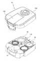
도 1은 본 발명에 따른 음료메이커의 외관 사시도와 분해 사시도.
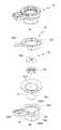
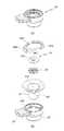
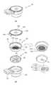
도 2는 본 발명에 따른 음료메이커의 요부 분해 사시도.
도 3 내지 도 8은 본 발명에 따른 음료메이커의 리셉터클 실시예들을 설명하기 위한 도면들.
도 9는 본 발명에 따른 음료메이커에서 카트리지를 설명하기 위한 도면.
도 10은 본 발명에 따른 음료메이커에서 거품발생수단을 설명하기 위한 도면.
도 11은 본 발명에 따른 음료메이커의 장착부재 설명을 위한 사진도.1 is an external perspective view and an exploded perspective view of a drink maker according to the present invention;
2 is a perspective exploded view of a drink maker according to the present invention.
3 to 8 are views for explaining receptacle embodiments of a beverage maker according to the present invention.
9 is a view for explaining a cartridge in a drink maker according to the present invention.
10 is a view for explaining the bubble generating means in the beverage maker according to the present invention.
11 is a photograph for explaining a mounting member of a drink maker according to the present invention.
본 발명은 다양한 변경을 가할 수 있고 여러 가지 형태를 가질 수 있는 바, 구현예(態樣, aspect)(또는 실시예)들을 본문에 상세하게 설명하고자 한다. 그러나 이는 본 발명을 특정한 개시 형태에 대해 한정하려는 것이 아니며, 본 발명의 사상 및 기술범위에 포함되는 모든 변경, 균등물 내지 대체물을 포함하는 것으로 이해되어야 한다.While the present invention has been described in connection with certain embodiments, it is obvious that the invention is not limited to the disclosed embodiments, but, on the contrary, is intended to cover various modifications and equivalent arrangements included within the spirit and scope of the invention. It is to be understood, however, that the invention is not intended to be limited to the particular forms disclosed, but on the contrary, is intended to cover all modifications, equivalents, and alternatives falling within the spirit and scope of the invention.
각 도면에서 동일한 참조부호, 특히 십의 자리 및 일의 자리 수, 또는 십의 자리, 일의 자리 및 알파벳이 동일한 참조부호는 동일 또는 유사한 기능을 갖는 부재를 나타내고, 특별한 언급이 없을 경우 도면의 각 참조부호가 지칭하는 부재는 이러한 기준에 준하는 부재로 파악하면 된다.In the drawings, the same reference numerals are used for the same reference numerals, and in particular, the numerals of the tens and the digits of the digits, the digits of the tens, the digits of the digits and the alphabets are the same, Members referred to by reference numerals can be identified as members corresponding to these standards.
또 각 도면에서 구성요소들은 이해의 편의 등을 고려하여 크기나 두께를 과장되게 크거나(또는 두껍게) 작게(또는 얇게) 표현하거나, 단순화하여 표현하고 있으나 이에 의하여 본 발명의 보호범위가 제한적으로 해석되어서는 안 된다.In the drawings, the components are expressed by exaggeratingly larger (or thicker) or smaller (or thinner) in size or thickness in consideration of the convenience of understanding, etc. However, It should not be.
본 명세서에서 사용한 용어는 단지 특정한 구현예(태양, 態樣, aspect)(또는 실시예)를 설명하기 위해 사용된 것으로, 본 발명을 한정하려는 의도가 아니다. 단수의 표현은 문맥상 명백하게 다르게 뜻하지 않는 한, 복수의 표현을 포함한다.The terminology used herein is for the purpose of describing particular embodiments only and is not intended to be limiting of the invention. The singular expressions include plural expressions unless the context clearly dictates otherwise.
본 출원에서, ~포함하다~ 또는 ~이루어진다~ 등의 용어는 명세서상에 기재된 특징, 숫자, 단계, 동작, 구성요소, 부분품 또는 이들을 조합한 것이 존재함을 지정하려는 것이지, 하나 또는 그 이상의 다른 특징들이나 숫자, 단계, 동작, 구성요소, 부분품 또는 이들을 조합한 것들의 존재 또는 부가 가능성을 미리 배제하지 않는 것으로 이해되어야 한다. In the present application, the term " comprising " or " consisting of ", or the like, refers to the presence of a feature, a number, a step, an operation, an element, a component, But do not preclude the presence or addition of one or more other features, integers, steps, operations, components, parts, or combinations thereof.
다르게 정의되지 않는 한, 기술적이거나 과학적인 용어를 포함해서 여기서 사용되는 모든 용어들은 본 발명이 속하는 기술 분야에서 통상의 지식을 가진 자에 의해 일반적으로 이해되는 것과 동일한 의미를 가지고 있다. 일반적으로 사용되는 사전에 정의되어 있는 것과 같은 용어들은 관련 기술의 문맥 상 가지는 의미와 일치하는 의미를 가지는 것으로 해석되어야 하며, 본 출원에서 명백하게 정의하지 않는 한, 이상적이거나 과도하게 형식적인 의미로 해석되지 않는다.Unless defined otherwise, all terms used herein, including technical or scientific terms, have the same meaning as commonly understood by one of ordinary skill in the art to which this invention belongs. Terms such as those defined in commonly used dictionaries are to be interpreted as having a meaning consistent with the contextual meaning of the related art and are to be interpreted as either ideal or overly formal in the sense of the present application Do not.
본 명세서에서 기재한 ~제1~, ~제2~ 등은 서로 다른 구성 요소들임을 구분하기 위해서 지칭할 것일 뿐, 제조된 순서에 구애받지 않는 것이며, 발명의 상세한 설명과 청구범위에서 그 명칭이 일치하지 않을 수 있다.
It is to be understood that the first to second aspects described in the present specification are merely referred to in order to distinguish between different components and are not limited to the order in which they are manufactured, It may not match.
본 발명에 따른 카트리지 분리수단을 구비한 음료 메이커를 설명함에 있어 편의를 위하여 엄밀하지 않은 대략의 방향 기준을 도 1 및 도 4를 참고하여 특정하면, 중력이 작용하는 방향을 하측으로 하여, 보이는 방향 그대로 상하좌우를 정한다.
In describing the beverage maker having the cartridge separating means according to the present invention, when an unambiguous approximate direction reference is specified with reference to Fig. 1 and Fig. 4, the direction in which the gravity acts is the lower side, The upper, lower, left, and right sides are determined as they are.
이하에서는 본 발명에 따른 카트리지 분리수단을 구비한 음료 메이커를 첨부된 도면을 참조하여 설명하기로 한다.BEST MODE FOR CARRYING OUT THE INVENTION Hereinafter, a beverage maker having cartridge separating means according to the present invention will be described with reference to the accompanying drawings.
우선 도 1 내지 도 11에 도시된 바와 같이, 본 발명에 따른 카트리지 분리수단을 구비한 음료 메이커는First, as shown in FIGS. 1 to 11, a beverage maker equipped with cartridge separating means according to the present invention
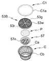
추출대상체(P)가 내장되는 카트리지(C);A cartridge C in which the extraction object P is embedded;
상기 카트리지(C)가 수용되는 끼움부(31A)를 갖는 본체(31)와, 이 끼움부(31A)에서 상기 카트리지(C)를 분리시키는 분리수단과, 손잡이(39)를 구비한 몸체(30')로 구성되고, 음료 추출부(11)에 결합되어 음료의 추출이 행해지는 리셉터클(30);을 포함하여 이루어진다.A separating means for separating the cartridge C from the
상기 카트리지(C)는 개구부(Ca)와 플렌지(Cb)를 구비한 바디, 추출대상체(P)가 상기 바디에 내장된 상태에서 상기 바디의 플렌지(Cb)에 결합되어 개구부(Ca)를 덮는 커버시트(C1)를 포함하여 이루어진다.The cartridge C includes a body having an opening Ca and a flange Cb and a cover which is coupled to the flange Cb of the body in a state where the extraction object P is embedded in the body, And a sheet C1.
미설명 부호인 53B와 57은 카트리지에 바디에 내장되어 커피 추출 시 크레마 향상을 위한 거품발생수단 등이 더 구비될 수 있음을 설명한다.And
상기 카트리지(C)에서 상기 개구부(Ca) 즉, 바디의 크기는 제조사별로 다르므로 본 발명은 제조사별로 다양한 카트리지(C)를 수용할 수 있는 리셉터클(30)을 다수 구비하고,Since the size of the opening Ca in the cartridge C differs depending on the manufacturer, the present invention includes a plurality of
상기 리셉터클(30)들을 음료 추출부(11)에 탈착 가능하도록 형성하여 카트리지(C)의 종류에 따라 리셉터클(30)을 교체하여 사용할 수 있다.The
이를 위하여 음료추출부(11)와 음료 추출용 노즐(미도시) 등이 구비된 전단부를 제외한 상부에 이종의 리셉터클(30)들을 보관할 수 있는 보관부(11A)가 형성된다.For this purpose, a
그리고 본 발명은 상기 보관부(11A)와 상기 음료추출부(11)를 개폐할 수 있는 제1커버덮개(15A)를 구비하여 리셉터클(30)의 보관 및 교체를 용이하도록 하였다.The present invention has a
본 발명은 상기 보관부를 개폐하는 제1커버덮개(15A)와 이 제1커버덮개(15A)에서 상기 음료추출부(11)만을 개폐할 수 있는 제2커버덮개(11B)를 구비함으로써, 리셉터클(30)의 교체 없이 카트리지(C)만을 교체하여 사용할 경우 리셉터클(30)의 탈착을 용이하도록 하고, 음료 메이커의 구성부를 손쉽게 청소하여 유지할 수 있다.The present invention has the
본 발명의 음료 메이커를 이루는 하우징(10)은 도 1 및 도 2 에 도시된 바와 같이, 음료수용부(10A)가 마치 동물이 입을 벌리고 있는 것과 같이 전방으로 개구된 형상을 가지며, 저면에는 커피 등의 잔액이 떨어져 수용되는 잔액트레이(19)가 구비되어 있으며, 분리가능한 그릴(19a)이 잔액트레이(19)의 저장 공간 상부에 구비되어 있다.As shown in FIGS. 1 and 2, the
상부에는 상기 음료추출부(11)와 리셉터클(30) 보관부(11A)가 구비되어 상기 제1커버덮개(15A)와 상기 제2커버덮개(11B)에 의하여 덮여 있다.The
또 도면에 도시되지 않았으나 상기 음료수용부(10A) 상부 위치에 해당하는 음료 추출부(11)의 하면에는 추출 음료 배출 노즐이 구비되어 있다.Also, although not shown in the drawing, an extractive drink discharge nozzle is provided on the lower surface of the
그리고 본 발명은 열수 공급을 위하여, 또 휴대성을 위하여 물탱크가 후면에 장착된다.In the present invention, a water tank is mounted on the rear surface for hot water supply and portability.
물탱크의 본질은 '추출용매 공급수단'이며, 음료의 본질상 수도시설에서 공급되는 물이나 생수 등 자연상태에서 획득할 수 있는 100% 물이거나, 음용 가능한 다양한 성분을 혼합한 물일 수 있으며, 이를 대표하여 '추출용매'라 할 수 있고,The essence of the water tank is the 'extraction solvent supply means', which can be 100% water that can be obtained in a natural state, such as water or living water supplied from a water supply facility in the essence of a drink, or water mixed with various drinking- Typically, it can be referred to as an 'extraction solvent'
따라서 하우징(10)에 장착되는 물탱크 뿐 아니라 수도꼭지, 정수기, 냉온수기 등과 연결되어 공급되는 모든 물 함유 용매 공급수단일 수 있다.Therefore, it may be any water-containing solvent supplying means connected to a faucet, a water purifier, a cold / hot water heater, etc. in addition to a water tank mounted on the
또 상기 하우징(10)의 기둥부(잔액트레이(19)가 구비된 베이스와 음료 추출부(11)를 연결하는 부분)에는 통상의 커피 메이커와 같이 고온ㅇ고압의 물을 분사하기 위하여 보일러 및 펌프, 이의 제어 및 안전성 보장을 위한 각종 센서 및 컨트롤러 역할을 하는 마이컴 등이 구비되어 있는데, 본 발명의 핵심을 집중적으로 설명하기 위하여 이에 대한 도면 및 설명은 편의상 생략한다.In order to spray hot water and high-pressure water, such as a typical coffee maker, the boiler and the pump (not shown) are connected to the column portion of the housing 10 (the portion connecting the base provided with the
도시된 형태는 음료 메이커 중 커피 추출형 커피 메이커이나, 본 발명의 개념은 다양한 용기형 캡슐(capsule)(또는 용기(pod)) 또는 부직포와 같은 다공성 외피로 포장된 팩 타입의 카트리지(C) 형태에 적용될 수 있으며, 이 카트리지(C)에 포장 제공될 수 있는 추출대상체(P)는 커피뿐 아니라 홍차, 녹차 등일 수 있고, 따라서 본 발명은 다양한 음료 제공을 위한 카트리지(C) 추출용 음료 메이커에까지 보호범위가 미치는 것으로 해석되어야 한다.The illustrated form is a coffee-extracting coffee maker in a beverage maker or the concept of the present invention is a packaged type cartridge (C) packaged in a porous casing such as a variety of container type capsules (or pods) The object to be extracted P which can be packaged in the cartridge C can be not only coffee but also black tea, green tea, etc., and thus the present invention can be applied to a drink maker for extracting a cartridge C for providing various drinks The scope of protection shall be construed as being.
또 상기 하우징(10)의 '음료수용부'는 컵이 수용될 수 있도록 전방 개구된 형태를 갖는데, 이는 단지 추출된 음료가 배출되는 부분을 대표하여 도시한 것으로, 단순히(또는 악위적으로) 통상의 컵 외에 병이나 다른 용기를 수용하기 위한 구조의 것도 본 발명의 보호범위에 속하는 것으로 해석되어야 한다.The 'beverage receptacle' of the
나아가 본 발명에서 '음료수용부'는 추출 음료를 공급하는 배출 노즐(도시된 구조 외에 비노출형 등 다양한 구조를 가질 수 있다)로부터 호스나 튜브를 통하여 다른 장소로 추출된 음료를 이송하여 컵, 병, 보온용기 등 다양한 용기에 담는 방식을 취하는 것도 본 발명의 보호범위에 속하는 것으로 해석되어야 한다.
Further, in the present invention, the 'beverage receptacle' may transfer the beverage extracted from the discharge nozzle (which may have various structures such as unexposed form) to another place through a hose or a tube, , And a method of putting it in various containers such as a warming container should be construed as falling within the scope of protection of the present invention.
다음으로 상기 리셉터클(30)은 카트리지(C) 끼움부(31A)를 형성하는 본체(31)와, 이 본체(31)를 둘러싼 상부측벽(30'a)을 갖는 몸체(30')로 구성되며,Next, the
상기 몸체(30')에는 상기 음료추출부(11)에 장착을 위한 암 또는 수 결합부가 형성되어 있으며, 음료추출부(11)에는 상기 암 또는 수 결합부에 대응하는 대응결합부가 형성된다.The body 30 'is provided with an arm or a male engaging portion for attaching to the
본질적으로 상기 끼움부(31A)의 형상 및 크기는 카트리지(C)에 따라 변형된다.Essentially, the shape and size of the
상술한 바와 같이, 본 발명에서는 다양한 카트리지(C)에 대해 음료 추출이 이루어지는 음료 메이커 구현을 위하여 복수의 리셉터클(30)을 도입하고 있으며, 본체(31)의 끼움부(31A)는 이종 또는 동종의 것이다.
As described above, in the present invention, a plurality of
이어서 상기 리셉터클(30)은 도 3 내지 도 7에 도시된 바와 같이, 끼움부(31A)에 수용된 카트리지(C)를 용이하게 분리하기 위한 분리수단을 포함하는데,The
상기 분리수단은 리셉터클 몸체에 구비되어 사용자가 파지하여 가압할 수 있는 가압체와 상기 가압체에 의하여 승하강이 이루어져 상기 끼움부에 수용된 카트리지의 플렌지 하면을 상측방향으로 가압하여 카트리지를 상기 리셉터클에서 이탈시키는 이탈체를 포함하여 이루어진다.The separating means is provided on the receptacle body to press up and down the cartridge by a pressing member which can be gripped and pressed by the user and a flange bottom face of the cartridge accommodated in the fitting portion by upward and downward movement by the pressing member to upwardly push the cartridge out of the receptacle And the like.
상기 가압체와 상기 이탈체로 구성되는 분리수단은 다양한 형태로 구현될 수 있는데,The separating means composed of the pressing body and the releasing body can be implemented in various forms,
이하에서는 상기 분리수단의 여러 실시예를 상세히 설명하도록 한다.
Hereinafter, various embodiments of the separating means will be described in detail.
상기 분리수단은 제1실시예로써, 도 3a에 도시된 바와 같이,(도 3a에서는 도 4 내지 도 7에 도시되어 있는 천공디스크(55)를 포함하는 본체(31)에 관한 구성이 도시되어 있지 않으나, 이는 상기 본체(31)가 리셉터클(30) 몸체(30')에 내장되었기 때문이며, 도 3a의 좌측 상부 일점 쇄선 원내 평면도에서 그 구성을 확인할 수 있으며(도면부호 미표기) 이에 관한 상세한 구성은 다른 도면과 관련된 설명에서 후술하도록 한다.)As shown in Fig. 3A, the separating means is a constitution of the
상기 가압체와 상기 이탈체로 대별되는 제1분리부재로 구현되는데,And a first separating member divided into the pressing body and the separating body,
상기 제1분리부재(33)는 상기 카트리지(C)의 플렌지(Cb)가 지지되는 리셉터클(30) 몸체(30')의 상부측벽(30'a)에 상하 방향으로 관통하여 형성된 분리홀(34)에 인출입되는 제1분리부(33D)와,The
상기 제1분리부(33D)와 연결되고 승강축(33C)을 구비한 제1연동부(33B)와, 상기 제1연동부(33B)와 연결된 제1작동부(33A)를 포함하여 이루어진다.A first interlocking
상기 제1연동부(33B)와 상기 제1작동부(33A)의 연결부에는 승강축(33C)이 구비되어 있으며,An elevating shaft 33C is provided at a connecting portion between the first interlocking
상기 승강축(33C)은 상기 몸체(30') 일측, 보다 상세하게는 상기 몸체(30')의 상부측벽 하부에 구비되어 있는 축설부(35)에 힌지 결합되어,The lifting shaft 33C is hinged to one side of the body 30 ', more specifically, a
상기 제1작동부(33A)를 하측 방향으로 가압함에 따라 상기 승강축을 축으로 시소운동이 되면서 상기 제1연동부(33B)가 승강되면서 상기 제1분리부(33D)가 상기 분리홀(34) 상측으로 승강하여 인출되고,As the
따라서 결국에는 상기 몸체(30')의 상부측벽(30'a)에 지지되는 카트리지(C)의 플렌지(Cb)가 상측 방향으로 가압하여 밀리게 됨으로써,Therefore, the flange Cb of the cartridge C, which is supported by the upper sidewall 30'a of the body 30 ', is pushed upward and pushed,
카트리지(C)를 리셉터클(30)에서 용이하게 분리할 수 있다.The cartridge C can be easily separated from the
상기 제1분리부재(33)가 상기 승강축(33C)을 통해 상기 몸체(30')의 축설부에만 힌지 결합되어 있을 경우, 상기 제1연동부(33B)는 자중에 의하여 하측 방향으로 하강하여, 결국에는 상기 제1분리부(33D)가 상기 분리홀(34)에서 이탈될 수 있다.When the first separating
따라서 종국적으로 상기 분리홀(34)에서 상기 제1분리부(33D)가 이탈할 경우, 별도의 가이드수단이 구비되어 있지 않기 때문에 제1작동부(33A)를 가압하였을 때 상기 제1분리부(33D)가 상기 분리홀(34)로 정확하게 인출되지 못하는 문제점이 발생할 여지가 있다.Therefore, when the
이에 본 발명은 상기 몸체(30') 둘레에 상기 제1연동부(33B)를 지지하는 받침부(30'b)를 구비하여 상기 제1분리부(33D)의 상측 일부가 상기 분리홀(34)에 이탈되지 않고 구속될 수 있도록 하여, 상기한 문제점을 미연에 방지할 수 있다.
Accordingly, the present invention is characterized in that the upper portion of the
이어서 상기 분리수단은 제2실시예로써, 상기 가압체와 상기 이탈체로 대별되는 제2분리부재로 구현되는데,The separating means is implemented as a second separating member which is divided into the pressing body and the separating body,
도 4에 도시된 바와 같이, 상기 제2분리부재는 상기 카트리지(C)의 플렌지(Cb)가 지지되고, 상기 본체(31)를 둘러싸는 몸체(30')의 상부측벽(30'a) 일부에 구속되어 승하강되는 제2분리부(37A)와,4, the second separating member is supported by the flange Cb of the cartridge C, and a part of the upper sidewall 30'a of the body 30 'surrounding the
상기 제2분리부(37A)와 연결되어 몸체에 구비된 손잡이(39)와 접하면서 제2분리부(37A)의 회전을 유도하는 제2작동부(37B)와,A
상기 손잡이(39) 상면에 상기 제2작동부(37B)의 회전방향으로 상향 경사지도록 형성된 사면부(39A)로 구성된다.And a
상기 제2분리부(37A)와 상기 제2작동부(37B)는 일체로 형성되며 상기 끼움부(31A) 둘레의 상부측벽(30'a)에 회전하면서 승하강 가능하도록 결합되고,The
상기 제2작동부(37B)는 상기 손잡이(39)의 상면에 형성된 함몰된 형태의 사면부(39A)와 접촉하면서 회전하여 제2분리부(37A)를 회전시킨다.The
이때 상기 손잡이(39)의 상면은 일측에서 타측을 향하여 상향 경사지도록 사면부(39A)를 갖도록 형성됨으로써, 상기 제2작동부(37B)가 일측 저부(39Aa)에서 타측 고부(39Ab)로 상기 사면부(39A)를 타고 회전하게 되면,The upper surface of the
사면부(39A)의 높이 변위에 의하여 상기 제2분리부(37A)는 상부측벽(30'a)을 타고 회전하면서 승강되어 떼어낸 카트리지(C)를 리셉터클(30)로부터 분리시킬 수 있다.The
따라서 상기 사면부(39A)의 저부(39Aa)는 상기 제2분리부재(37)의 락킹위치를 의미하고, 상기 사면부(39A)의 고부(39Ab)는 제2분리부재(37)의 개방위치를 의미한다.Therefore, the bottom 39Aa of the
즉, 카트리지(C) 수용 시 상기 제2작동부(37B)를 일측 저부(39Aa)에 위치한 상태에서 카트리지(C)를 리셉터클(30)의 끼움부(31A)에 끼운 후 리셉터클(30)을 음료 추출부(11)에 장착하여 음료를 추출하고,That is, when the cartridge C is received, the cartridge C is inserted into the
카트리지(C) 교체가 필요할 경우 리셉터클(30)을 음료 추출부(11)에서 빼낸 후 상기 제2작동부(37B)를 회전시켜 카트리지(C)를 리셉터클(30)로부터 분리시킨 후 사용자는 카트리지(C)의 플렌지(Cb)를 파지하여 잡아당김으로써 카트리지(C)의 완전 분리를 쉽게 행할 수 있으며, 이후 다른 카트리지(C)를 끼운 후 음료 추출을 수행하여 다량의 음료가 필요할 때 카트리지(C) 교체 시간을 줄일 수 있다.
When the cartridge C needs to be replaced, the
다음으로 본 발명에 따른 분리수단의 제3실시예로써, 상기 가압체와 상기 이탈체로 대별되는 제3분리부재로 구현되는데,Next, as a third embodiment of the separating means according to the present invention, a third separating member, which is divided into the pressing body and the separating body,
도 5 및 도 6에 도시된 바와 같이, 상기 제3분리부재는 상기 카트리지(C)가 지지되고, 상기 본체(31)를 둘러싸는 몸체(30')의 상부측벽(30'a) 일부를 형성하면서 상기 리셉터클(30)에 힌지 결합된 제3분리부(38)와,5 and 6, the third separating member is formed by forming a part of the upper side wall 30'a of the body 30 'supporting the cartridge C and surrounding the
상기 제3분리부(38A)와 연결되어 하측으로 가압 시 상기 제3분리부(38A)가 회동축(38C)을 축으로 승강되도록 하는 제3작동부(38B)로 구성된다.And a
도면에서는 상기 상부측벽이 몸체와 분리된 것으로 도시되어 있으나, 이는 본체(31)의 결합관계의 설명의 편의를 위한 순서로 도시한 것이며, 상기 상부측벽(30'a)과 상기 몸체(30')는 일체로 형성된다.The upper sidewall 30 'a and the body 30' are illustrated as being separated from the body. However, the upper sidewall 30 'a and the body 30' Are integrally formed.
상기 제3분리부(38A)는 끼움부(31A) 둘레의 몸체(30') 상부측벽(30'a)으로써 카트리지(C)의 플렌지(Cb)가 상면에 지지되고, 이후 제3분리부(38A)의 승강에 의하여 카트리지(C)의 분리가 완료되는 것은 상기 제1실시예와 같으나,The
상기 제3분리부(38A)는 상기 제2분리부(37A)와 달리, 상기 끼움부(31A) 둘레의 상부측벽(30'a) 중 일부를 형성하고 있고,Unlike the
회동축(38C)을 통해 상기 제3작동부(38B)를 하측 방향으로 가압하면 상기 제3분리부(38A)가 상측 방향으로 승강되면서 카트리지(C)를 리셉터클(30)로부터 분리시킨다.The
이때 상기 제3작동부(38B)와 제3분리부(38A)로 구성되는 제3분리부재(38)는 시소운동에 의하여 회동축(38C)에 구속된 상태로 제3분리부(38A)가 승강되며 따라서 제3분리부(38A)의 말단부는 호선 형태의 궤적을 이룬다. At this time, the third separating member 38 composed of the
이에 반해 상기 카트리지(C)는 상기 끼움부(31A)에 구속되어 있으므로 수직방향으로 직선 형태로 승하강될 수밖에 없으므로,On the other hand, since the cartridge C is restrained by the
상기 제3분리부(38A)는 상기 상부측벽(30'a)의 일부만을 대체하도록 형성되어 제3작동부(38B)의 작동 시 카트리지(C) 플렌지(Cb) 저면 일부에 접촉하는 제3분리부(38A)의 말단부에 힘이 집중되면서 상승됨으로써, 적은 힘으로도 카트리지(C)의 분리가 가능하다.The
또 카트리지(C) 분리 시 상기 플렌지(Cb)와 상기 상부측벽(30'a) 사이에는 이격부가 형성되고, 따라서 사용자는 상기 이격부를 통해 상기 카트리지(C)의 플렌지(Cb)를 보다 쉽게 파지하여 분리할 수 있는 장점이 있다.Further, when the cartridge C is detached, a spacing portion is formed between the flange Cb and the upper sidewall 30'a so that the user can grasp the flange Cb of the cartridge C more easily through the spacing portion There is an advantage of separating.
도 6에 도시된 제3분리부재는 도 5에 도시된 제3분리부재와 그 작동 원리가 동일하며, 그 구체적 구성만이 약간 다를 뿐이고,The third separating member shown in Fig. 6 has the same operation principle as the third separating member shown in Fig. 5, only the specific configuration thereof is slightly different,
도 5 또는 도 6에 도시된 분리수단은 시소운동을 통한 카트리지 분리라는 점에서 그 본질이 같으므로, 본 발명의 권리해석이 제한되어 해석되어서는 안될 것이다.
The separation means shown in FIG. 5 or 6 is essentially the same in that it is a cartridge separation through seesaw motion, so the right interpretation of the present invention should not be construed as limited.
그리고 상기 제3분리부재는 도 8에 도시된 바와 같이, 상기 회동축(38C)에 구비되어 상기 제3분리부(38A)를 리셉터클(30)의 끼움부(31A) 방향으로 탄성력을 발휘하는 탄성부재(38D)가 구비된다.8, the third separating member is provided on the
도 8에서는 도 6에 도시된 형태의 분리수단에 탄성부재가 구비되어 있는 것으로 도시되어 있으나, 도 5의 형태에도 상기 탄성부재(38D)가 구비될 수 있음은 물론이며, 당업자라면 충분히 예측하여 재현할 수 있을 것이다.In FIG. 8, the separating means shown in FIG. 6 is shown to have an elastic member. However, it should be understood that the elastic member 38D may be provided in the form of FIG. 5, You can do it.
상기 탄성부재(38D)를 통해 상기 끼움부(31A) 방향으로 제3분리부(38A)가 탄성, 지지되므로 사용자가 제3작동부(38B)의 가압을 해제하면 상기 제3분리부(38A)는 원상 복귀하여 상기 상부측벽(30'a)을 구성하게 되므로 다른 카트리지(C)를 끼움부(31A)에 끼울 때 사용자는 고온으로 상승된 제3분리부(38A)를 가압하여 제자리 위치시켜야 하는 등의 번거로움을 줄이고, 화상 역시 방지할 수 있다.The
상기 탄성부재는 상기 제1실시예에도 적용 가능하다.
The elastic member is also applicable to the first embodiment.
다음으로 본 발명은 상기 리셉터클(30) 본체(31)를 몸체에 탈착시키기 쉬우면서 체결 후 그 상태가 안정적으로 유지시켜 후술하는 거품증가수단을 통한 크레마 향상을 유도한다.Next, the
이를 위하여 본 발명은 도 4에 도시된 바와 같이, 상기 리셉터클(30)의 본체(31) 둘레에 복수개의 결합돌기(301)가 구비되며,To this end, as shown in FIG. 4, a plurality of
상기 결합돌기(301)가 상기 몸체(30') 상부측벽(30'a)에 형성된 결합홈(302)에 구속된 상태로 회전하여 결합되는 것이 바람직하다.It is preferable that the
상기 결합돌기(301)가 삽입되어 안내되는 결합홈(302)은 리셉터클(30)의 최초 장착 시 결합돌기(301)가 쉽게 결합홈(302)으로 진입할 수 있도록 상부측벽(30'a) 일부가 수직방향으로 절개된 수직절개부(302A)를 갖고,The
수직절개부(302A)에 삽입 완료 시 상기 결합돌기(301)가 상기 수직절개부(302A)와 수평된 방향 일측, 또는 타측 회전하여 견고한 체결력을 갖도록 하는 수평절개부(302B)를 갖는다.And a horizontal cut-out
상기 수직, 수평절개부(302A)(302B)를 통해 리셉터클(30)의 본체(31) 장착이 이루어지므로 몸체(30')와 본체(31)를 분리하여 청소하기 쉽고, 리셉터클(30) 저면부에 형성되는 거품발생수단 등 다양한 구성부 또한 분리하여 청소할 수 있다.Since the
도 3, 도 5 내지 도 7에 도시되지 않았으나, 상기 결합돌기와 상기 결합홈으로 구성되는 결합수단이 도 3, 도 5 내지 도 7의 리셉터클에 적용될 수 있음은 당연하다.
3 and 5 to 7, it is needless to say that the coupling means composed of the coupling protrusion and the coupling groove can be applied to the receptacle of Figs. 3, 5 to 7.
또한 본 발명은 음료 추출부(11)에 상기 리셉터클(30)이 직접 장착되어 음료 추출이 이루어질 뿐만 아니라,In addition, the present invention is not only capable of extracting beverage by mounting the receptacle (30) directly to the beverage extracting section (11)
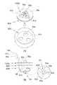
도 3a 및 도 11에 도시된 바와 같이, 상기 리셉터클(30)을 사용자가 손쉽게 취급하여 음료 추출을 행할 수 있도록 하는 장착부재(320)를 더 포함하여 이루어질 수 있다.As shown in FIGS. 3A and 11, the
도 1 및 도 2에서는 상기 리셉터클(30)이 음료 추출부에 직접 장착된 후 음료 추출이 행해지는 것으로 도시되어 있으나,1 and 2 show that the beverage extraction is performed after the
도 3에 도시된 장착부재(320)를 도입하여 리셉터클(30)의 사용을 용이하게 하면서 카트리지의 교체 시 장착부재(320)를 통해 리셉터클을 손쉽게 취급한 상태에서 카트리지를 교체할 수 있도록 함으로써 사용자의 편의를 보장할 수 있다.It is possible to introduce the mounting
이를 위하여 도 3a에 도시된 바와 같이, 상기 장착부재(320)는 사용자가 파지할 수 있는 핸들(330)을 구비하고, 상기 리셉터클(30)이 장착되는 장착부(321A)를 갖는 홀더(321)를 포함하여 이루어진다.3A, the mounting
이러한 장착부재를 통한 리셉터클의 음료 추출은 특히 에스프레소 커피 머신에 주로 이용되는 것으로써, 상기 홀더의 저면에는 추출된 음료가 배출되는 배출노즐이 구비된다.The beverage extraction of the receptacle through such a mounting member is mainly used in an espresso coffee machine, and a discharge nozzle for discharging the extracted beverage is provided on the bottom of the holder.
상기 홀더(321)는 상측 외주면에 돌출된 장착돌기(322)를 통해 상기 음료추출부에 장착되는데, 보다 상세하게는 상기 음료추출부(11) 하측에 구비되는 열수 공급 노즐을 상기 홀더(321)의 장착부(321A)가 덮으면서 장착되도록 할 수 있다.The
도면에 도시되지 않았으나, 장착부재(320)가 음료추출부 하부에 장착될 경우 상기 음료 추출부는 열수가 유통되는 유통수단만이 구비되어 열수 공급 노즐을 통해 장착부재(320)에 결합된 리셉터클(30)에 직접 열수 분출이 이루어지도록 한다.Although not shown in the drawing, when the mounting
이때 상기 음료추출부는 열수 공급 노즐 주변에 상기 장착부재(320)의 장착돌기(322)가 삽입될 수 있는 장착홈(미도시)이 형성되며, 장착부재(320)를 상기 배출 노즐을 덮도록 한 후 핸들(330)을 회전시켜 장착돌기(322)가 장착홈에 삽입되면서 리셉터클(30) 상부가 밀폐되도록 이루어진다.At this time, the beverage extracting unit has a mounting groove (not shown) in which a mounting
핸들(330)을 갖는 장착부재(320)를 통해 리셉터클(30)의 장착이 이루어지므로 사용자는 제2커버덮개(15B)를 일일이 개폐하여 카트리지 교체를 행해야 하는 번거로움을 줄일 수 있다.Since the
또 본 발명은 이종의 리셉터클(30)을 구비하여 다양한 카트리지를 사용할 수 있는 구성이므로,In addition, since the present invention is configured to use various cartridges with different types of
상기 장착부재(320)에 상기 리셉터클(30) 결합수단을 차용한 장착수단을 도입하여, 하나의 장착부재(320)만으로 다수의 리셉터클(30)을 사용할 수 있도록 하였다.A mounting means for boring the coupling means of the
도 3a에 도시된 바와 같이, 상기 홀더(321)는 상기 장착부(321A)를 형성하는 측벽이 절개된 형태의 고정홈(323)이 구비되고, 상기 고정홈(323)에 상기 리셉터클(30)의 제1작동부(33A)가 삽입, 결합된다.3A, the
상기 고정홈(323)은 홀더(321)의 측벽 상측 단부에서 수직방향으로 절개된 수직절개홈(323A)과, 이 수직절개홈(323A)의 하측 단부에서 수평방향으로 절개된 수평절개홈(323B)으로 구성된다.The fixing
상기 수평절개홈(323B)은 상하 소정 간격을 갖도록 형성되어 상기 제1작동부가 상기 승강축을 축으로 하여 승하강 될 수 있는 여유 공간을 확보하는 것이 바람직하다.The
그리고 상기 리셉터클(30)은 제1작동부(33A)가 형성된 반대 방향에 상기 결합돌기와 같은 형상의 고정돌기(301)가 구비될 수 있고, 상기 홀더(321)의 내주면에는 상기 고정돌기가 걸리는 걸림홈(미도시)이 원주 방향을 따라 형성될 수 있다.The
따라서 사용자는 상기 리셉터클(30)의 고정돌기를 상기 걸림홈에 끼운 후 상기 제1작동부를 상기 수직절개홈(323A)으로 삽입하여 끼운 다음,Accordingly, the user inserts the fixing protrusion of the
제1작동부를 회전시켜 수평절개홈(323B)에 손잡이(39)가 결합되도록 함으로써, 리셉터클(30)을 상기 홀더(321)의 장착부에 장착할 수 있다.The
도면에 도시되지 않았으나 상지 수평절개홈(323B)에는 상기 제1작동부(33A)가 결합 시 결합상태를 유지시키는 체결돌기 또는 체결홈을 더 구비할 수 있으며, 상기 손잡이(39)에는 이에 대응하는 대응돌기 또는 대응홈이 더 구비될 수 있고,Although not shown in the drawings, the upper
돌기와 홈의 형태뿐만 아니라, 원터치 방식으로 체결상태를 유지 또는 해제할 수 있는 체결수단이 더 구비될 수 있다.It is possible to provide not only the shape of the protrusion and the groove but also the fastening means capable of maintaining or releasing the fastened state by the one-touch method.
사용자는 리셉터클을 상기 홀더에 체결한 후 리셉터클(30) 끼움부(31A)에 카트리지를 끼우고 장착부재(320)를 상기 음료추출부에 장착한 후 음료 추출을 행한다.After the receptacle is fastened to the holder, the user inserts the cartridge into the
음료 추출이 완료되면 사용자는 장착부재(320)를 음료추출부로부터 분리시킨 후 상기 리셉터클(30)에 구비된 분리수단(도 3a 내지 도 7에 도시된)을 통해 카트리지를 교체하여 음료추출을 반복적으로 행할 수 있다.After the beverage extraction is completed, the user removes the mounting
또 이종의 카트리지를 사용할 경우 사용자는 상기 리셉터클(30)의 고정과 반대방향으로 손잡이를 돌려 홀더로부터 리셉터클을 분리시키고 다른 리셉터클(30)을 다시 고정한 후 카트리지를 교체하여 다른 음료의 추출을 행할 수 있다.Further, when using different kinds of cartridges, the user can rotate the handle in the direction opposite to the fixing of the
본 발명은 도 3a에 도시된 형태의 리셉터클 뿐만 아니라, 도 4 내지 도 7에 도시된 리셉터클을 모두 상기 장착부재에 장착하여 사용할 수 있고, 이는 도 3a에서 설명한 장착수단을 통해 통상의 기술자라면 충분히 예측하여 변형, 치환, 수정하여 재현할 수 있을 것이다.(도 3b 에서는 도 6의 리셉터클을 변형하여 상기 장착부재에 결합될 수 있음을 도시하고 있다.)The present invention can be used not only with the receptacle of the type shown in Fig. 3A but also with the receptacle shown in Figs. 4 to 7 mounted on the mounting member, (Fig. 3 (b) shows that the receptacle of Fig. 6 can be modified to be coupled to the mounting member).
나아가 본 발명은 카트리지 교체 시 사용자의 편의를 위하여 상기 핸들(330)에 힌지 결합되어 리셉터클(30)의 측벽을 파지, 고정할 수 있는 파지부재(331)를 더 포함한다.Further, the present invention further includes a gripping
도 11에 도시된 바와 같이, 상기 파지부재(331)는 회동 가능하도록 핸들(330)에 구비되어 있어, 음료추출 시에는 핸들(330)에 접은 상태로 음료 추출을 행하고,11, the gripping
음료 추출 후 카트리지 교체가 필요할 경우, 상기 파지부재(331)를 회동 시켜 파지부재(331)의 말단부가 리셉터클(30)의 측벽을 가압, 파지하도록 한 후, 그 상태에서 쓰레키통 등의 수거통에 장착부재(320)를 털어내는 것만으로 카트리지의 분리를 가능하도록 함으로써, 사용자가 화상을 입을 수 있는 위험을 방지하였다.When the cartridge needs to be replaced after the beverage is extracted, the gripping
즉, 음료 추출 후 카트리지 교체 시 사용자는 상기 파지부재(331)를 펼친 상태에서 리셉터클(30)을 고정시킨 후, 상기 분리수단을 통해 카트리지를 분리시키고, 장착부재(320)를 기울여 털어내는 동작만으로 카트리지를 분리할 수 있도록 하여, 사용자의 편의를 증대시켰다.That is, when the cartridge is replaced after extracting the beverage, the user may fix the
본 발명은 결합돌기(301; 도 4 참고)를 통해 리셉터클(30) 몸체(31)가 본체(30')에 결합되어 있으나, 장착부재(320)를 흔들어 털면서 카트리지를 제거할 경우, 상기 결합돌기가 결합홈으로부터 이탈될 수 있으므로 상기 파지부재(331)를 이용하여 리셉터클(30)이 분리되는 문제점을 미연에 방지할 수 있다.The
이는 캡슐형 카트리지뿐만 아니라 부직포 또는 분말 형태의 추출대상체를 도 7의 리셉터클(30)을 이용하여 음료 추출을 행할 때 사용자의 편의성이 더욱 증대되는데,The convenience of the user is further enhanced when the beverage extraction is performed using the
즉, 도 7의 리셉터클(30)에서 부직포나 분말 형태 등의 추출대상체가 거름망(20)에 수용될 경우 교체 시 사용자가 직접 손으로 추출대상체를 제거하면 고온에 의하여 화상의 위험이 있고, 제거 작업이 매우 번거로우므로,That is, when the extraction object such as a nonwoven fabric or a powder form is accommodated in the
상기 파지부재(331)를 회전시켜 거름망을 리셉터클(30)에 단단히 고정시킨 후 그 상태에서 장착부재(320)를 쓰레기통 등에 털어내는 것만으로 추출대상체의 제거가 이루어진다.
The extraction object is removed only by rotating the grasping
다음으로 도 4 내지 도 6 및 도 9에 도시된 리셉터클에 수용되는 용기(pod)형 카트리지(C)는 바디 저면의 천공이 필수적이어서,Next, the pod type cartridge C accommodated in the receptacle shown in Figs. 4 to 6 and Fig. 9 is required to drill the bottom of the body,
천공돌기(55a)를 본질로 하는 천공디스크(55)로 구성된 하부 파괴수단을 구비한 것으로 도시되어 있다.And a piercing
도면에 도시되지 않았으나 상기 커버시트(C1)를 천공하여 열수를 공급하는 상부 파괴수단이 구비됨은 당연하다.Although it is not shown in the drawing, it is a matter of course that an upper breaking means for piercing the cover sheet C1 to supply hot water is provided.
그러나 카트리지(C)의 파괴, 천공이 필수적인 것은 아니어서 이를 포괄하여 추출용매 '유통수단'으로 지칭하고 있다.However, destruction and perforation of the cartridge C are not essential, so they are referred to as an extraction solvent 'distribution means'.
도시된 용기(pod)형 카트리지(C)의 바디 하면은The bottom surface of the illustrated pod type cartridge C
카트리지(C)의 리셉터클(30) 본체(31) 끼움부(31A) 장착 즉시,Upon mounting the
또는 상부 파괴수단을 통한 고온ㅇ고압의 추출용 물 공급으로 수압에 의하여 카트리지(C) 바디 저면이 변형 하강시Or the supply of water at a high temperature and a high pressure through the upper breaking means, the water level of the body bottom of the cartridge (C)
천공디스크(55)의 천공돌기(55a)와 접촉하여 천공, 파괴가 이루어질 수 있다.The piercing
상기 천공디스크(55) 하부에는 거품디스크(59)가 배열되어 있다.A
상기 거품디스크는 열에 강하고 환경호르몬 노출 위험이 적은 실리콘 소재나 기타 안전소재로 제조되는 것이 바람직하며,The foam disk is preferably made of a silicone or other safety material that is heat-resistant and low in the risk of exposure to environmental hormones,
도 4 내지 도 6에서 천공디스크(55) 중앙에 치우친 추출 음료 통과부를 통하여 배출되는 추출음료가 방사상으로 배열된 안내로를 따라 거품디스크(59) 외곽으로 퍼진 후,4 to 6, after the extracted beverage discharged through the extract beverage passing portion deviating from the center of the perforating
각 안내로 끝의 통공을 통과하면서 체류시간의 증대로 커피, 특히 에스프레스 특유의 풍미를 향상시키는 거품 또는 크레마(Crema, 조밀한 황금빛 갈색의 거품으로 에스프레소(Espresso) 샷을 덮는다)를 증가시킨다.Increasing the residence time by passing through the holes at the end of each guide increases the coffee, especially the foam or crema (which covers the espresso shot with a dense golden brown foam) that improves the flavor peculiar to the espress.
그리고 본 발명의 리셉터클(30)은 크레마 향상을 위하여 거품발생수단을 더 포함하여 이루어질 수 있는데,Further, the
먼저, 제1거품발생수단(60A)과 관련하여 도 10의 [A]의 결합사시도(그 외 다른 구성요소는 도 1 내지 도 9 참조)에서 확인할 수 있는 바와 같이,First, as can be seen from the combined perspective view of Fig. 10A (other components are shown in Figs. 1 to 9) with respect to the first foam generating means 60A,
추출대상체(P), 특히 커피(P)가 내장된 카트리지(C)를 수용하는 끼움부(31A)를 갖고, 추출액 소통로가 형성된 본체(31)를 구비한 리셉터클(30)에 배열되며, 소통로와 연통되는 형태로 장착된다.Is arranged in a receptacle (30) having a main body (31) in which an extraction liquid channel is formed and has a fitting portion (31A) for receiving a cartridge (C) As shown in FIG.
이러한 제1거품발생수단(60A)은 고정력 보장을 위하여 별도의 패널부재를 도입하고, 이 패널부재 역시 리셉터클(30) 본체(31)의 소통로와 연통되는 통과부를 갖는다.The first foam generating means 60A introduces a separate panel member for ensuring the fixing force, and the panel member also has a passing portion communicating with the communication passage of the
특히 제1거품발생수단을 리셉터클(30) 본체(31)에 고정하기 위한 패널부재(F)는 원소스 멀티유즈(One-source Multi-use 또는 One-source Multi-tasking) 경향에 맞게 천공디스크(55)가 기능하며,Particularly, the panel member F for fixing the first foam generating means to the
패널부재의 통과부는 천공디스크(55)의 통과부(55b)가 기능하게 된다. 천공돌기(55a)를 중심으로 등간격으로 배열된 세 통과부(55b)에 대응되게 상기 제1거품발생수단은 연통이 가능한 세 배출부(61b)를 구비하고 있다.And the passing portion of the panel member functions as the passing
이러한 제1거품발생수단(60A)의 핵심은 통과부(55b)를 부분적으로 가리는 가요성 차폐부(61a)이다.The core of the first foam generating means 60A is a
보다 본질적으로는 패널부재와 무관하게 제1거품발생수단(60A)의 핵심은 상기 리셉터클(30) 본체(31), 특히 저면부(37)의 소통로와 연결되는 추출액 배출부(61b)와, 상기 배출부 둘레에 구비된 가요성 차폐부(61b)라 할 수 있다. 이 경우에도 충분히 가요성 차폐부(61b)가 진동하고, 이에 의하여 낙하, 배출되는 추출액에 충격을 가하면서 거품 또는 크레마 발생량을 증가시킬 수 있다.Essentially, the core of the first foam generating means 60A, irrespective of the panel member, comprises an extract
여기에 더해 패널부재(F) 또는 천공디스크(55)를 도입하는 경우에는 패널부재(F) 또는 천공디스크(55)의 통과부로 인하여 가요성 차폐부(61b)가 자유단 형태로 노출되고, 추출액은 추출액 통과부(55b)를 거쳐 배출되므로 추출액은 보다 집중적으로 가요성 차폐부(61b)와 접촉, 충돌하게 된다.In addition, when the panel member F or the
가요성 차폐부(61b)가 추출액 통과부(55b)를 가리는 정도는 거품 또는 크레마 발생량과, 추출액 배출유량 등을 고려하여 조정될 수 있다.The extent to which the
한편, 제1거품발생수단(60A)은 도 10 [A] 및 [A]의 하부 일점 쇄선 원내 단독 사시도(그 외 다른 구성요소는 도 1 내지 도 9 참조)에서 확인할 수 있는 바와 같이,On the other hand, as can be seen from the single perspective view of the lower one-dot chain line of the lower one-dot chain line of Figs. 10A and 10A (other components are shown in Figs. 1 to 9)
리셉터클(30) 본체(31), 천공디스크(55), 이후 도 10 [B]와 관련하여 설명할 제2거품발생수단(60B) 사이의 밀폐성 확보 편리성 등을 고려하여 한 몸으로 성형될 수 있으나,In consideration of the easiness of ensuring the hermeticity between the
가요성 차폐부(61a)에 해당하는 부분만을 가요성 합성수지나, 실리콘 시트(또는 필름)으로 제조할 수 있다.Only the portion corresponding to the
이 가요성 차폐부 또는 제1거품발생수단(나아가 제2거품발생수단까지)은 고온에서도 환경호르몬 노출 위험이 적은 실리콘 소재나 기타 안전소재인 것이 바람직하다.Preferably, the flexible shielding or first foam generating means (and further to the second foam generating means) is a silicone material or other safety material with a low risk of exposure to environmental hormones even at high temperatures.
'가요성'(可撓性) 차폐부(61a)는 배출되는 추출액의 압력 또는 충격이나, 펌프 등으로 인한 음료메이커 자체의 진동으로 인하여 미세하게 진동하여 추출액을 튕기는 역할을 하게 되어, 그만큼 거품 또는 크레마의 발생량을 증가시킬 수 있다.The 'flexible' shielding
패널부재(F) 또는 천공디스크(55)의 통과부 크기 및 수에 맞게 이러한 가요성 차폐부(61a) 및 추출액 배출부(61b)의 배열 위치, 크기, 수가 정해지며,Size, and number of the
이 가요성 차폐부(61a)(또는 제1거품발생수단(60A))의 두께는 진동특성 보장, 밀폐성 보장, 내구성 보장 등을 고려하여 선택된다.The thickness of the
나아가 제2거품발생수단(60B)은 도 10 [B]의 분해 단면도(그 외 다른 구성요소는 도 1 내지 도 9 참조)에서 확인할 수 있는 바와 같이,Further, as can be seen from the exploded cross-sectional view of Fig. 10B (other components are shown in Figs. 1 to 9)
리셉터클(30), 특히 본체(31)에 수용되고, 상기 제1거품발생수단 하부에 배열되어, 추출액이 통과하는 소통공(63)을 갖고,The
이 소통공은 상부의 패널부재(F) 또는 천공디스크(55)의 통과부, 제1거품발생수단(60A)의 배출부(61b)와 연결되고,This communication hole is connected to the passing portion of the upper panel member F or the
하부의 리셉터클(30) 본체(31) 저면부의 소통로와 연결된다.And is connected to the communication path of the bottom portion of the lower
도 10 [B] 및 [B]의 하부 우측 일점 쇄선 원내 단독 확대 사시도에서 확인할 수 있는 바와 같이,As can be seen from a single enlarged perspective view in the lower right one-dot chain line of Figs. 10 [B] and [B]
추출액 소통공(63)은 상부에서 하부로 가면서 지름이 가변되어, 협(狹)-광(廣)-협(狹) 크기를 갖는 제1 내지 제3 소통부(63a,63b,63c)로 구성되거나 ,The extract
더 바람직하기로는 협(狹)-광(廣)-협(狹)-광(廣)-협(狹)를 갖는 제1 내지 제5 소통부(63a,63b,63c,63d,63e)로 구성되어 있어, 특유의 오리피스 구조로 거품 또는 크레마(Crema) 발생량을 더욱 증가시킬 수 있다.More preferably, the first to
또 실리콘, 기타 엘라스토머 소재나, 그 외 다양한 가요성 소재로 제2거품발생수단(60B)을 제조하는 경우, 1mm 보다 작은 크기를 갖는 소통공(63)이 막힐 수 있는데, 추출액의 압력에 의하여 소통공이 변형(하부로 쳐지는 형태로 변형됨)되는 경우 ,When the second foam generating means 60B is made of silicon, other elastomer material or various other flexible materials, the
소통공의 광(廣)폭 부위인 제2 및 제4 소통부(63b)(63d)로 인하여 협(狹)폭 부위인 제1, 제3, 제5 소통부(63a)(63c)(63e)가 확장될 수 있어, 그만큼 소통공(63)이 막히지 않도록 하는 효과를 얻을 수 있다.Third, and
또 제2거품발생수단(60B)의 소통공(63)은 도 10 [B] 및 [B]의 하부 우측 일점 쇄선 원내 단독 확대 사시도에서 확인할 수 있는 바와 같이,The communicating
제1소통부 보다 큰 제2소통부, 제2소통부 보다 작은 제3소통부, 제3소통부 보다 큰 제4소통부, 제4소통부 보다 작은 제5소통부가 상부에서 차례로 형성되어 있으며,A second communication portion having a larger size than the first communication portion, a third communication portion smaller than the second communication portion, a fourth communication portion larger than the third communication portion, and a fifth communication portion smaller than the fourth communication portion,
상세한 크기(각 소통부의 평단면도를 관찰했을 때, 각 단면적의 크기)는The detailed size (the size of each cross-sectional area when viewing the flat cross-section of each traffic section)
제2소통부 ≒ 제4소통부 〉 제5소통부 〉제1소통부 〉제3소통부의 크기를 갖는다.The second communication portion? Fourth communication portion> the fifth communication portion> the first communication portion> the third communication portion.
그러나 제1소통부 ≒ 제3소통부 ≒ 제5소통부의 크기여도 무방하며, 가능한 제1 내지 3 또는 제1 내지 5의 소통부 크기라 서로 다른 것이 바람직하다. 이에 따라 각 소통부에서의 압력차이로 거품 또는 크레마의 양이 증가되는 효과를 얻을 수 있다.However, it is preferable that the size of the first communication portion ≒ the third communication portion ≒ the fifth communication portion, and the sizes of the communication portions 1 through 3 or the first through fifth communication portions are different from each other. Accordingly, the effect of increasing the amount of foam or crema due to the pressure difference in each communication part can be obtained.
필요에 따라 상기 소통공에서 지름이 가변되어 협(狹)폭과 광(廣)폭이 반복되는 소통부의 수는 더 증가될 수 있으며, 이때 박판 형태의 연결체(63A)에 형성된 소통부(63c)의 구조는 상호 이격된 형태로 복수 개 구비될 수 있다.
If necessary, the diameter of the communicating hole may be varied in the communication hole so that the number of communication parts in which the narrow width and the wide width are repeated may be further increased. At this time, the
나아가 패널부재(F) 또는 천공디스크(55)와, 제1거품발생수단(60A), 제2거품발생수단(60B)은 각각 가장자리에 중첩부 또는 테두리(55c)(61c)(65a)를 갖고, 이 부분에서 추출액 누설 방지를 위한 밀폐성 및 고정력을 얻으며,Further, the panel member F or the
제1거품발생수단(60A) 및 제2거품발생수단(60B)은 상부의 패널부재(F) 또는 천공디스크(55)와 하부의 리셉터클(30) 본체(31)의 저면부(37) 사이에 개재되는 형태로 장착된다.The first foam generating means 60A and the second foam generating means 60B are disposed between the upper panel member F or the
나아가 제2거품발생수단(60B)은 사발 형태와 유사하여, 제1거품발생수단(60A) 하부에 공간부(65)를 형성하게 되어 추출액의 체류 공간을 확보하고, 제1거품발생수단(60A)의 가요성 차폐부(61a)가 진동할 수 있는 공간을 보장하게 된다.
Further, the second foam generating means 60B is similar to the bowl shape, so that the
나아가 본 발명에 따른 음료 메이커은 도 7에서 도시된 바와 같이, 변형된 리셉터클(30)을 더 포함하여 이루어질 수 있다.Further, the beverage maker according to the present invention may further include a modified
도 7의 [A]는 상부방향에서 관찰하는 경우의 도면이고, 도 7의 각 [B]는 분해사시도와 함께 하부방향에서 관찰하는 경우의 도면인데,[A] in Fig. 7 is a view in an upward direction, and [B] in Fig. 7 is a view in a downward direction together with an exploded perspective view.
즉, 상술한 바와 같이, 본 발명에서 추출대상체(P)가 내장되는 카트리지(C)는 캡슐 형태뿐만 아니라 부직포 또는 커피가루 형태로 가능하며, 이때 상기 리셉터클은 상기 몸체(30')에 결합되는 상기 카트리지(C)가 수용되는 수용부를 갖는 거름망을 포함하여 이루어진다.That is, as described above, in the present invention, the cartridge C in which the extraction target body P is embedded can be formed in the form of a nonwoven fabric or a coffee powder as well as a capsule. In this case, And a sieve having a receptacle in which the cartridge C is received.
상기 거름망(20)은 상기 리셉터클을 구성하는 몸체(30')와 그 형태를 달리하고 추출대상체(P)가 직접 수용되어 음료 추출이 행해진다.The
상기 거름망(20)은 리셉터클 몸체(30')의 제1장착부에 밀착 안치되는데, 거름망(20)과 몸체(30')의 제1장착부 사이에는 거품증가체(40)가 개재된다.The
거품증가체는 합성고무 등의 엘라스토머나 실리콘 소재로 이루어져 가요성 특성, 연질특성을 갖는 것이 바람직한데, 특히 고온ㅇ고압의 열수에 대해서도 변형되지 않고 유해물질(특히 환경호르몬)이 유출되지 않도록 하는 소재인 것이 바람직하다.The foam increasing body is preferably made of an elastomer such as synthetic rubber or a silicone material and has flexibility and softness. Especially, it is preferable to use a material which prevents the harmful substance (especially, the environmental hormone) .
도 7 [B]에서 거품증가체(40)의 상면에는 열수에 의하여 추출된 커피가 중공인 거품증가부(41)로 안내되면서도 지체될 수 있도록 방사상으로 형성된 안내돌기(43)와 안내돌기(43)와 연결된 체류돌기(45)가 형성되어 있어, 거품 또는 크레마(Crema, 조밀한 황금빛 갈색의 거품으로 에스프레소(Espresso) 샷을 덮는다)가 1차적으로 증가될 수 있도록 되어 있다.7 (B), on the upper surface of the
도 7 [B]의 일점 쇄선 원 내 단면 확대도로 과장되게 도시한 바와 같이, 통공 형태인 거품증가부(41)는 제1통과부(41a), 제1체류부(41b), 제2통과부(41c), 제2체류부(41d), 제3통과부(41e)가 상부에서 하부로 연속 형성된 구조이며,As shown in an exaggerated sectional view in the one-dot chain line circle in Fig. 7 [B], the
열수가 펌프에 의하여 가압 공급되면서 분말커피를 추출하여 제조된 에스프레소가 특유의 배출압력에 의하여 거품증가부(41)를 통과하게 되고,The espresso produced by extracting the powdered coffee while the hot water is pressurized and supplied by the pump passes through the
커피메이커의 펌프를 가동하는 모터에서 전달되는 진동에 의하여 연질ㅇ가요성 거품증가체(40)가 진동하면서The flexible
액상 에스프레소는 좁은 제1통과부(41a), 확장된 제1체류부(41b), 다시 좁은 제2통과부(41c), 확장된 제2체류부(41d), 좁은 제3통과부(41e)를 통과하면서 거품이 증가하게 된다.The liquid espresso has a narrow
그 상대적인 단면적의 크기는The size of the relative cross-
[ 제2통과부(41c) > 제1통과부(41a) ≥ 제3통과부(41e) > 제1체류부(41b) ≥ 제3통과부(41e) ] 또는(The
[ 제2통과부(41c) > 제3통과부(41e) ≥ 제1통과부(41a) > 제3통과부(41e) ≥ 제1체류부(41b) ]인 것이(The
크레마가 가장 풍부하게 생성되는 것으로 밝혀졌다.Crema was found to be the most abundant.
다음으로 거름망(20)은 분말커피 수용부(20a)를 갖고, 상부 외측에 플렌지(23)와, 그 내측에 지지턱(25)을 갖고, 추출공(21)이 형성되어 있는데, 특히 복수의 추출공(21)이 저면 외곽 부위에 배열되어 있어 밀폐커버(100)의 중앙 부위 열수 주입공(102)에 대하여 어긋난 위치에 배열되고, 더 바람직하기로는 가능한 먼 거리에 배열되어 충분히, 그리고 골고루 열수가 분말커피와 접촉한 후 최대한 에스프레소가 추출ㅇ형성되도록 되어 있다.Next, the
특히 추출공(21)은 금속, 특히 부식 방지를 위하여 SUS 소재로 구성된 거름망(20)의 저면을 프레스로 가압하여 상향돌기(21A)를 형성하고, 이 상향돌기의 정점을 연마 가공하여 추출공(21)을 형성함으로써 추출공을 가능한 작게 형성하면서도,Especially, the
상향돌기(21A) 정점에 형성된 추출공(21)이 분말커피에 의하여 잘 막히지 않게 된다(왜냐하면 상향돌기(21A)의 점점에 열수에 의하여 유동되는 분말커피가 머물지 못하고 상향돌기를 따라 미끄러지기 때문으로, 그만큼 분말커피 입자와 추출공의 직접적인 접촉시간이 짧다).The
또 상향돌기(21A)로 인하여 그 반대 부위인 거름망(20)의 저면에서는 요홈(21a)이 형성되는데, 청소시, 거름망(20)의 저면에서 흐르는 물을 접촉하면 혹 추출공(21)에 끼인 커피 입자도 쉽게 분리ㅇ제거될 수 있다.In addition, a
아울러 외곽 부위 상향돌기(21A)의 내측에는 저항돌기(27)가 돌출되어 있는데, 이 역시 프레스 가공으로 가압 형성된 것이어서 그 반대면에는 요홈(27a)이 형성되어 있다.In addition, a
상기 저항돌기(27)는 열수에 의하여 유동하는 커피 입자와 접촉하여 커피입자 유동특성을 불규칙하고 복잡하게 하여 추출 성능을 증가시키게 되며,The resistance protrusions 27 are in contact with the coffee particles flowing by the hot water to make the flow characteristics of the coffee particles irregular and complicated to increase the extraction performance,
그 저면의 요홈(27a)은 거품증가체(40) 상면과 공간을 형성하게 되어,The
거품증가체의 안내돌기(43)와 체류돌기(45)가 수행하는 크레마의 1차적으로 증가기능을 보강하여 크레마의 증대 효과를 배가할 수 있도록 하게 된다.The primary increase function of the crease performed by the
다시 도 7에서 본 발명의 리셉터클(30) 몸체에 상기 거름망을 덮는 밀폐커버(100)가 힌지 결합되어, 거름망에 추출대상체를 넣은 후 밀폐커버를 덮은 후 음료 추출부에 장착하고 음료 추출을 행한다.7, the sealing
도 7에 도시된 리셉터클은 도 4 내지 도 6에 도시된 리셉터클과 달리 커버시트 천공이 필요하지 않으므로 밀폐커버(100) 중앙에 천공수단이 통과할 수 있는 통과공(102)이 형성되며, 밀폐커버(100)를 여닫을 수 있는 파지부(101)가 일측에 구비된다.Since the receptacle shown in FIG. 7 does not require a cover sheet perforation unlike the receptacle shown in FIGS. 4 to 6, a through
상기 밀폐커버(100)는 회동축(103)이 구비되고, 이 회동축이 도 5에서 손잡이에 구비되는 절개부(39B)에 결합됨으로써, 부직포 형태의 카트리지 추출에 이용될 수 있다.
The sealing
이상에서 본 발명을 설명함에 있어 첨부된 도면을 참조하여 특정 형상과 구조를 갖는 카트리지 분리수단을 구비한 음료 메이커를 위주로 설명하였으나 본 발명은 당업자에 의하여 다양한 수정, 변경 및 치환이 가능하고, 이러한 수정, 변경 및 치환은 본 발명의 보호범위에 속하는 것으로 해석되어야 한다.
While the present invention has been described with reference to the accompanying drawings, it is to be understood that the invention is not limited to the disclosed embodiments, but, on the contrary, is intended to cover various modifications and equivalent arrangements included within the spirit and scope of the appended claims. , Changes and substitutions are to be construed as falling within the scope of protection of the present invention.
C : 카트리지
10 : 하우징20 : 거름망
30 : 리셉터클30' : 몸체
31 : 본체31A : 끼움부
33: 제1분리부재33A : 제1작동부
33B : 제1연동부33C : 승강축
33D : 제1분리부34 : 분리홀
35 : 축설부
37 : 제2분리부재37A : 제2분리부
37B : 제2작동부
38 : 제3분리부재38A : 제3분리부
38B : 제3분리부
39 : 손잡이
320 : 장착부재321 : 홀더
323 : 고정홈330 : 핸들C: Cartridge
10: housing 20:
30: receptacle 30 ': body
31:
33: first separating
33B: first interlocking portion 33C: elevating shaft
33D: first separator 34: separation hole
35: Axis
37: second separating
37B: second operating portion
38: third separating
38B: third separator
39: Handle
320: mounting member 321: holder
323: fixing groove 330: handle
Claims (4)
Translated fromKorean상기 카트리지가 수용되는 끼움부를 포함하는 몸체와, 상기 몸체에 구비되어 상기 끼움부에서 상기 카트리지를 분리시키는 분리수단을 포함하여 이루어지고, 음료 추출부에 결합되어 음료의 추출이 행해지는 리셉터클;을 포함하여 이루어지되,
상기 분리수단은
상기 몸체에 구비되어 사용자가 파지하여 가압할 수 있는 가압체와,
상기 가압체에 의하여 승하강이 이루어져 상기 끼움부에 수용된 카트리지의 플렌지 하면을 상측방향으로 가압하여 상기 끼움부에서 카트리지를 이탈시키는 이탈체를 포함하여 이루어지는 것을 특징으로 하는 카트리지 분리수단을 구비한 음료 메이커.A cartridge in which an extraction object is embedded;
And a receptacle provided in the body for separating the cartridge from the fitting portion and connected to the beverage extracting portion to extract the beverage, the body including the fitting portion in which the cartridge is accommodated However,
The separating means
A pressing body provided on the body and capable of holding and pressing by a user,
And a deflector which moves upward and downward by the pressing body to press the lower surface of the flange of the cartridge accommodated in the fitting portion upward to release the cartridge from the fitting portion. .
상기 분리수단에서
상기 이탈체는 상기 카트리지의 플렌지가 지지되는 상기 몸체의 상부측벽에 형성된 분리홀에 상하방향으로 인출입되는 제1분리부와, 상기 제1분리부와 연결되고 상기 몸체의 축설부에 승강축이 힌지 결합되어 있는 제1연동부로 구성되며,
상기 가압체는 상기 제1연동부와 연결되어 가압 시 상기 제1분리부가 상기 승강축을 축으로 승강되도록 하는 제1작동부로 구성되는 것을 특징으로 하는 카트리지 분리수단을 구비한 음료 메이커.The method according to claim 1,
In the separating means
The first separator is connected to the first separator. The first separator is connected to the first separator. The elevator shaft is connected to the shaft of the body. And a first interlocking portion hinged to each other,
Wherein the presser body is constituted by a first actuating part connected to the first interlocking part and configured to move up and down the first separating part about the lifting shaft when pressurized.
상기 분리수단에서
상기 이탈체는 상기 카트리지의 플렌지가 지지되고, 상기 본체를 둘러싸는 몸체의 상부 측벽에 구속되어 승하강되는 제2분리부로 구성되며,
상기 가압체는 상기 제2분리부와 연결되어 손잡이와 접하면서 제2분리부의 회전을 유도하는 제2작동부와, 상기 손잡이 상면에 상기 제2작동부의 회전방향으로 상향 경사지도록 형성된 사면부로 구성되는 것을 특징으로 하는 카트리지 분리수단을 구비한 음료 메이커.The method according to claim 1,
In the separating means
And the second separator is supported by the flange of the cartridge and is raised and lowered by restricting the upper sidewall of the body surrounding the body,
The pressing member includes a second operating portion connected to the second separating portion and contacting the handle to induce rotation of the second separating portion, and a slope portion formed on the upper surface of the handle to be inclined upward in the rotating direction of the second operating portion And a cartridge separating means for separating the cartridge.
상기 리셉터클을 음료 추출부에 장착시키기 위하여 리셉터클 장착부를 갖는 홀더와, 핸들을 구비한 장착부재를 더 포함하여 이루어지되,
상기 홀더에는 수직절개홈과 수평절개홈으로 구성되는 고정홈이 구비되고,
상기 리셉터클을 상기 장착부에 장착 시 상기 리셉터클의 가압체가 상기 수직절개홈에 삽입 후 수평절개홈으로 회전하면서 장착되는 것을 특징으로 하는 카트리지 분리수단을 구비한 음료 메이커.
4. The method according to any one of claims 1 to 3,
A holder having a receptacle mounting portion for mounting the receptacle on the beverage extracting portion, and a mounting member having a handle,
The holder is provided with a fixing groove formed by a vertical cutting groove and a horizontal cutting groove,
Wherein when the receptacle is mounted on the mounting portion, the pressing body of the receptacle is inserted into the vertical cutting groove and then mounted while rotating into the horizontal cutting groove.
Priority Applications (1)
| Application Number | Priority Date | Filing Date | Title |
|---|---|---|---|
| PCT/KR2013/011323WO2014092406A1 (en) | 2012-12-10 | 2013-12-09 | Universal beverage maker |
Applications Claiming Priority (4)
| Application Number | Priority Date | Filing Date | Title |
|---|---|---|---|
| KR20120142957 | 2012-12-10 | ||
| KR1020120142957 | 2012-12-10 | ||
| KR1020130066805 | 2013-06-11 | ||
| KR1020130066805AKR20140074802A (en) | 2012-12-10 | 2013-06-11 | Beverage maker equipped with separator cartridge |
Publications (2)
| Publication Number | Publication Date |
|---|---|
| KR20140074809Atrue KR20140074809A (en) | 2014-06-18 |
| KR101448275B1 KR101448275B1 (en) | 2014-10-13 |
Family
ID=49857082
Family Applications (3)
| Application Number | Title | Priority Date | Filing Date |
|---|---|---|---|
| KR1020130013205AExpired - Fee RelatedKR101326682B1 (en) | 2012-12-10 | 2013-02-06 | Universal beverage maker |
| KR1020130066805APendingKR20140074802A (en) | 2012-12-10 | 2013-06-11 | Beverage maker equipped with separator cartridge |
| KR1020130093598AExpired - Fee RelatedKR101448275B1 (en) | 2012-12-10 | 2013-08-07 | Beverage maker equipped with separator cartridge |
Family Applications Before (2)
| Application Number | Title | Priority Date | Filing Date |
|---|---|---|---|
| KR1020130013205AExpired - Fee RelatedKR101326682B1 (en) | 2012-12-10 | 2013-02-06 | Universal beverage maker |
| KR1020130066805APendingKR20140074802A (en) | 2012-12-10 | 2013-06-11 | Beverage maker equipped with separator cartridge |
Country Status (1)
| Country | Link |
|---|---|
| KR (3) | KR101326682B1 (en) |
Families Citing this family (4)
| Publication number | Priority date | Publication date | Assignee | Title |
|---|---|---|---|---|
| CN104905677B (en)* | 2014-03-10 | 2017-11-17 | 珠海格力电器股份有限公司 | Beverage machine and preparation method of beverage |
| WO2021246889A1 (en)* | 2020-06-04 | 2021-12-09 | Weadd, Lda | Beverage preparation systems and processes, including portion holder with enhanced single portion |
| US12171361B2 (en) | 2020-12-30 | 2024-12-24 | Sharkninja Operating Llc | Hybrid receptacle beverage brewing system |
| USD1048792S1 (en) | 2023-04-12 | 2024-10-29 | Sharkninja Operating Llc | Coffee machine |
Family Cites Families (3)
| Publication number | Priority date | Publication date | Assignee | Title |
|---|---|---|---|---|
| KR20040097866A (en)* | 2003-05-13 | 2004-11-18 | 넥솔테크(주) | An Apparatus and Opening Method for Sealed Container Having a Subsidenced Groove at the Side Wall |
| DK1500357T3 (en)* | 2003-07-23 | 2006-06-19 | Monodor Sa | Process for preparing a beverage from a capsule and device for initiating the process |
| KR20100117253A (en)* | 2009-04-24 | 2010-11-03 | 이경수 | Filter mounting device of and mounting method thereof |
- 2013
- 2013-02-06KRKR1020130013205Apatent/KR101326682B1/ennot_activeExpired - Fee Related
- 2013-06-11KRKR1020130066805Apatent/KR20140074802A/enactivePending
- 2013-08-07KRKR1020130093598Apatent/KR101448275B1/ennot_activeExpired - Fee Related
Also Published As
| Publication number | Publication date |
|---|---|
| KR20140074802A (en) | 2014-06-18 |
| KR101448275B1 (en) | 2014-10-13 |
| KR101326682B1 (en) | 2013-11-08 |
Similar Documents
| Publication | Publication Date | Title |
|---|---|---|
| KR101572956B1 (en) | Beverage maker for all cartridge | |
| US9756974B2 (en) | Beverage cartridge replacement for single-serving beverage brewers | |
| KR101351782B1 (en) | Beverage maker for extracting cartridges equipped with bubble increasing means | |
| US9271597B2 (en) | Single serving reusable brewing material holder | |
| US8967038B2 (en) | Cartridge for use in coffee maker | |
| TWI386179B (en) | Integrated cartridge containing a substance for extracting a beverage | |
| US11832755B2 (en) | Brewing material container for a beverage brewer | |
| JP6386529B2 (en) | Method, apparatus and capsule for extracting beverages | |
| EP3089634B1 (en) | Beverage machine | |
| KR20110053368A (en) | Coffee holding arm of hand loading coffee machine | |
| JPH05192247A (en) | Detachable cartridge extractor | |
| KR20140129098A (en) | Beverage forming device and method with activation button | |
| KR101448275B1 (en) | Beverage maker equipped with separator cartridge | |
| KR20140129096A (en) | Beverage forming device and method with moving beverage cartridge holder | |
| KR20140129097A (en) | Beverage forming device and method with multi-part beverage cartridge holder | |
| KR101323361B1 (en) | Beverage maker for extracting cartridges equipped with universal cap | |
| KR20140029718A (en) | Water purifier with capsule coffee extractor | |
| CN120265187A (en) | Beverage preparation system and method including portion container with enhanced single portion | |
| KR20150066189A (en) | Receptacle universal beverage maker | |
| KR101600563B1 (en) | Beverage maker for extracting cartridges equiped with receptacle storage | |
| KR101581930B1 (en) | Universal beverage maker | |
| CN103860020A (en) | Beverage maker equipped with cartridge separator | |
| CN115734727B (en) | Beverage preparation system and method including a portion container with enhanced seal and closure | |
| KR101572952B1 (en) | Receptacle for beverage | |
| WO2012128477A2 (en) | Insert module for a beverage capsule |
Legal Events
| Date | Code | Title | Description |
|---|---|---|---|
| A201 | Request for examination | ||
| PA0109 | Patent application | St.27 status event code:A-0-1-A10-A12-nap-PA0109 | |
| PA0201 | Request for examination | St.27 status event code:A-1-2-D10-D11-exm-PA0201 | |
| PG1501 | Laying open of application | St.27 status event code:A-1-1-Q10-Q12-nap-PG1501 | |
| E902 | Notification of reason for refusal | ||
| PE0902 | Notice of grounds for rejection | St.27 status event code:A-1-2-D10-D21-exm-PE0902 | |
| E13-X000 | Pre-grant limitation requested | St.27 status event code:A-2-3-E10-E13-lim-X000 | |
| P11-X000 | Amendment of application requested | St.27 status event code:A-2-2-P10-P11-nap-X000 | |
| P13-X000 | Application amended | St.27 status event code:A-2-2-P10-P13-nap-X000 | |
| E701 | Decision to grant or registration of patent right | ||
| PE0701 | Decision of registration | St.27 status event code:A-1-2-D10-D22-exm-PE0701 | |
| PR0701 | Registration of establishment | St.27 status event code:A-2-4-F10-F11-exm-PR0701 | |
| PR1002 | Payment of registration fee | St.27 status event code:A-2-2-U10-U11-oth-PR1002 Fee payment year number:1 | |
| PG1601 | Publication of registration | St.27 status event code:A-4-4-Q10-Q13-nap-PG1601 | |
| P22-X000 | Classification modified | St.27 status event code:A-4-4-P10-P22-nap-X000 | |
| PN2301 | Change of applicant | St.27 status event code:A-5-5-R10-R13-asn-PN2301 St.27 status event code:A-5-5-R10-R11-asn-PN2301 | |
| LAPS | Lapse due to unpaid annual fee | ||
| PC1903 | Unpaid annual fee | St.27 status event code:A-4-4-U10-U13-oth-PC1903 Not in force date:20171001 Payment event data comment text:Termination Category : DEFAULT_OF_REGISTRATION_FEE | |
| P22-X000 | Classification modified | St.27 status event code:A-4-4-P10-P22-nap-X000 | |
| PC1903 | Unpaid annual fee | St.27 status event code:N-4-6-H10-H13-oth-PC1903 Ip right cessation event data comment text:Termination Category : DEFAULT_OF_REGISTRATION_FEE Not in force date:20171001 |