KR20140072821A - Multitouch tactile device with multifrequency and barycentric capacitive detection - Google Patents
Multitouch tactile device with multifrequency and barycentric capacitive detectionDownload PDFInfo
- Publication number
- KR20140072821A KR20140072821AKR1020130150217AKR20130150217AKR20140072821AKR 20140072821 AKR20140072821 AKR 20140072821AKR 1020130150217 AKR1020130150217 AKR 1020130150217AKR 20130150217 AKR20130150217 AKR 20130150217AKR 20140072821 AKR20140072821 AKR 20140072821A
- Authority
- KR
- South Korea
- Prior art keywords
- row
- frequency
- voltage
- column
- voltages
- Prior art date
- Legal status (The legal status is an assumption and is not a legal conclusion. Google has not performed a legal analysis and makes no representation as to the accuracy of the status listed.)
- Granted
Links
Images


Classifications
- G—PHYSICS
- G01—MEASURING; TESTING
- G01R—MEASURING ELECTRIC VARIABLES; MEASURING MAGNETIC VARIABLES
- G01R27/00—Arrangements for measuring resistance, reactance, impedance, or electric characteristics derived therefrom
- G01R27/02—Measuring real or complex resistance, reactance, impedance, or other two-pole characteristics derived therefrom, e.g. time constant
- G01R27/26—Measuring inductance or capacitance; Measuring quality factor, e.g. by using the resonance method; Measuring loss factor; Measuring dielectric constants ; Measuring impedance or related variables
- G01R27/2605—Measuring capacitance
- G—PHYSICS
- G06—COMPUTING OR CALCULATING; COUNTING
- G06F—ELECTRIC DIGITAL DATA PROCESSING
- G06F3/00—Input arrangements for transferring data to be processed into a form capable of being handled by the computer; Output arrangements for transferring data from processing unit to output unit, e.g. interface arrangements
- G06F3/01—Input arrangements or combined input and output arrangements for interaction between user and computer
- G06F3/03—Arrangements for converting the position or the displacement of a member into a coded form
- G06F3/041—Digitisers, e.g. for touch screens or touch pads, characterised by the transducing means
- G06F3/0416—Control or interface arrangements specially adapted for digitisers
- G06F3/04166—Details of scanning methods, e.g. sampling time, grouping of sub areas or time sharing with display driving
- G—PHYSICS
- G06—COMPUTING OR CALCULATING; COUNTING
- G06F—ELECTRIC DIGITAL DATA PROCESSING
- G06F3/00—Input arrangements for transferring data to be processed into a form capable of being handled by the computer; Output arrangements for transferring data from processing unit to output unit, e.g. interface arrangements
- G06F3/01—Input arrangements or combined input and output arrangements for interaction between user and computer
- G06F3/03—Arrangements for converting the position or the displacement of a member into a coded form
- G06F3/041—Digitisers, e.g. for touch screens or touch pads, characterised by the transducing means
- G06F3/044—Digitisers, e.g. for touch screens or touch pads, characterised by the transducing means by capacitive means
- G06F3/0446—Digitisers, e.g. for touch screens or touch pads, characterised by the transducing means by capacitive means using a grid-like structure of electrodes in at least two directions, e.g. using row and column electrodes
- G—PHYSICS
- G06—COMPUTING OR CALCULATING; COUNTING
- G06F—ELECTRIC DIGITAL DATA PROCESSING
- G06F2203/00—Indexing scheme relating to G06F3/00 - G06F3/048
- G06F2203/041—Indexing scheme relating to G06F3/041 - G06F3/045
- G06F2203/04104—Multi-touch detection in digitiser, i.e. details about the simultaneous detection of a plurality of touching locations, e.g. multiple fingers or pen and finger
Landscapes
- Engineering & Computer Science (AREA)
- General Engineering & Computer Science (AREA)
- Theoretical Computer Science (AREA)
- Physics & Mathematics (AREA)
- General Physics & Mathematics (AREA)
- Human Computer Interaction (AREA)
- Position Input By Displaying (AREA)
- Measurement Of Length, Angles, Or The Like Using Electric Or Magnetic Means (AREA)
- Electronic Switches (AREA)
- Force Measurement Appropriate To Specific Purposes (AREA)
- User Interface Of Digital Computer (AREA)
- Geophysics And Detection Of Objects (AREA)
Abstract
Translated fromKoreanDescription
Translated fromKorean본 발명의 분야는 정전용량 검출을 이용한 촉각 또는 "터치스크린" 표면들에 대한 것으로, 좀더 구체적으로 2 개의 동시적 가압들 (presses) 의 검출을 허용하는 이른바 "멀티터치" 촉각 표면들에 대한 것이다. 이러한 기능은 예를 들어 이미지 "줌들" 또는 회전들을 이행하는데 필수적이다. 본 발명은 다양한 용도들에 적용될 수도 있으나, 항공 분야 및 항공기 계기판들의 제약들에 특히 알맞다.The field of the invention is for tactile or "touch screen" surfaces using capacitive sensing, and more particularly for so-called "multi-touch" tactile surfaces that allow detection of two simultaneous presses . Such a function is necessary, for example, to implement image "zooms" or rotations. The present invention may be applied to a variety of applications, but is particularly suited to the constraints of aerospace and aircraft instrumentation.
이른바 "투영" 정전용량 검출은 사용자의 손가락들 또는 임의의 다른 전도성 포인팅 오브젝트의 근접에 의해 도입되는 커패시턴스에서의 국지적 변동들을 검출하도록 배열된 검출 매트릭스를 생성하는 것으로 구성된다. 이른바 투영 정전용량 기술은 2 개의 주요 변형들, 즉:Called " projection "capacitance detection is constituted by generating a detection matrix arranged to detect local variations in the capacitance introduced by the proximity of the user's fingers or any other conductive pointing object. The so-called projection capacitive technology has two main variants, namely:
- 매트릭스의 터치키들의 어레이의 행들 그리고 그 다음에 열들을 판독하는 것으로 구성되는 "자기 정전용량" 검출;"Self-capacitance" detection consisting of reading rows of arrays of touch keys of the matrix and then columns;
- 매트릭스의 터치키들의 어레이의 각각의 교차점을 판독하는 것으로 구성되는 이른바 "상호 정전용량" 검출을 도입한다.Called " reciprocal capacitance "detection consisting of reading each intersection of the array of touch keys of the matrix.
"상호 정전용량" 기술은 패드 전체의 판독을 요구한다. 따라서, 매트릭스가 N 개의 행들 및 M 개의 열들을 포함하는 경우, N × M 번의 획득들을 이행할 필요가 있어, 큰 사이즈이며, 높은 해상도이고, 낮은 응답 시간을 갖는 패드들을 생성하는데 문제가 되게 한다. 또한, "상호 커패시턴스" 하에 측정될 커패시턴스는 "자기 정전용량" 하에 입수된 것보다 낮으므로, 사용자가 장갑들을 이용하는데 문제가 되게 한다.The "reciprocal capacitance" technique requires reading of the entire pad. Thus, if the matrix contains N rows and M columns, it is necessary to implement N x M acquisitions, which makes it problematic to create pads of large size, high resolution, and low response time. Also, the capacitance to be measured under "mutual capacitance " is lower than that obtained under" self capacitance "
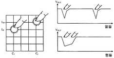
"자기 정전용량" 검출의 이점은, 위의 패드에 있어서, 매트릭스의 판독을 이행하기 위해 시스템이 단지 N+M 개의 취득만을 요구한다는 것이다. 도 1 은 이러한 원리를 도시한다. 이 도 1 에서, 제 1 손가락이 열 (CI) 과 행 (LJ) 의 제 1 교차점의 레벨에서 가압하고, 제 2 손가락이 열 (CK) 과 행 (LL) 의 제 2 교차점의 레벨에서 가압한다. 행들 및 열들의 출력 전압들 (VOUT) 은 쉽게 식별가능한 레벨에서의 강하들을 보인다. 각각의 레벨에서의 강하 주위의 전압들의 측정들은 호출된 행들 및 열들을 정확하게 식별하는 것을 가능하게 한다.An advantage of the "self capacitance" detection is that for the above pad, the system requires only N + M acquisitions in order to perform the reading of the matrix. Figure 1 shows this principle. In this Figure 1, the second crossing of the first finger is open (CI) and line the pressure at the level of the first intersection and the second finger is open (CK) and the line (LL) of (LJ) Press in the level. The output voltages (VOUT ) of the rows and columns show the drops at an easily identifiable level. Measurements of voltages around the drop at each level enable accurate identification of the rows and columns being called.
그러나, 이러한 후자의 기법은 결점을 보인다. 검출된 행들 및 열들을 사용자의 손가락들에 의해 실제로 터치된 정확한 교차점이라고 하는 것이 항상 간단하지만은 않다. 실제 터치되지 않았으나, 가능성 있는 교차점들은 일반적으로 "고스트 (ghost) 들"이라고 불린다. 이러한 어려움에 대응하기 위해, 일 기법은 2 개의 상이한 획득 주파수들에서 매트릭스의 스캔을 이행하는 것으로 구성된다. 2012 년 6 월자 "SID 2012 DIGEST" 에서 발행된 공개문헌 "Eliminating Ghost Touches on a Self-Capacitive Touch-Screen" 에 이러한 기법이 설명된다.However, this latter technique has drawbacks. It is not always simple to say that the detected rows and columns are the exact intersections actually touched by the user's fingers. Potential intersections that are not actually touched are commonly referred to as "ghosts. &Quot; To cope with this difficulty, one technique consists in implementing a scan of the matrix at two different acquisition frequencies. This technique is described in an open publication entitled "Eliminating Ghost Touches on a Self-Capacitive Touch-Screen" published in June 2012 "SID 2012 DIGEST".
이러한 기법을 적절히 이해하기 위해서는, 정전용량식 매트릭스 디바이스를 나타내는 전자 모델들을 이용할 필요가 있다. 전도 행들 (conducting rows) 및 전도 열들 (conducting columms) 로 구성되는 전극들의 매트릭스를 포함하는 용량성 촉각 디바이스를 전기적으로 설명하는 간소화된 모델이 존재한다. 모델은 패드 상의 그의 손가락의 표면을 투영함으로써 오퍼레이터의 손가락이 매트릭스와 용량성으로 커플링되는 가압의 표현으로 구성된다. 이러한 표면은 제 1 행 방향 및 제 2 열 방향인 적어도 2 개의 전극들을 커버한다. 그 다음에 접지와 관련된 적어도 하나의 행 또는 열 사이에 오퍼레이터가 커패시턴스 (Cd) 를 추가하는 것으로 여겨진다. 그러나 이러한 모델은 국지적으로 있을 뿐이고, 측정의 환경을 고려하지 않는다.To properly understand these techniques, it is necessary to use electronic models representing capacitive matrix devices. There is a simplified model for electrically describing a capacitive haptic device including a matrix of electrodes consisting of conducting rows and conducting columns. The model consists of a representation of the pressure by which the operator's finger is capacitively coupled to the matrix by projecting the surface of his finger on the pad. This surface covers at least two electrodes that are in the first row direction and the second column direction. It is then assumed that the operator adds capacitance Cd between at least one row or column associated with the ground. However, these models are only local and do not take into account the measurement environment.
도 3 은 정전용량식 매트릭스 디바이스의 좀더 정교한 모델을 도시한다. 각각의 행은 사실 아날로그 스위치들을 통해 측정 및/또는 전력 공급 디바이스에 접속된다. 이러한 스위치들은 접지에 대한 커플링 커피시턴스 (Cm) 를 제공하고, 측정된 신호의 감쇠를 야기하는 전기 저항 (Rm) 을 보인다.Figure 3 shows a more sophisticated model of a capacitive matrix device. Each row is actually connected to a measurement and / or power supply device via analog switches. These switches provide the coupling coffee-to-ground (Cm ) and show the electrical resistance (Rm ) that causes the attenuation of the measured signal.
또한, 각각의 행은 전력 공급 지점과 손가락의 접촉 지점 사이에 소정의 저항을 보이는 ITO (Indium Tin Oxide) 유형의 투명 재료로 구성되며, 이러한 저항은 모두 손가락이 접속 지점으로부터 더 멀리 떨어질수록 더 높다. Rt 가 터치키와 터치키의 다음 접속에 대한 저항일 경우, 열 (n) 상의 가압과 매트릭스의 가장자리 사이의 저항은 n.Rt 이다.Further, each row is made of a transparent material of the Indium Tin Oxide (ITO) type showing a predetermined resistance between the power supply point and the contact point of the finger, and this resistance is higher as the finger is farther from the connection point . If Rt is the resistance to the next connection of the touch key and the touch key, the resistance between the pressure on the row n and the edge of the matrix is nRt .
또한, 행들 및 열들의 어레이가 상호간에 커플링된다. 사실, 트랙들의 각각의 교차부에 커패시턴스 (Cp) 가 존재하며, 각각의 행은 n 개의 열에 의해 단절되고, 또한 행들 또는 열은 그것들의 이웃들과 커플링된다. 이러한 커플링은 커패시턴스 (CIc) 로 도 3 에서 도시된다. 마지막으로, 터치패드, 터치패드의 커넥터 장치, 및 디바이스를 구성하는 기계적 아이템들 사이의 커플링 커패시턴스들, 뿐만 아니라 전자 측정 디바이스로 행들 및 열들을 연결하는 다양한 트랙들 사이의 상호 커플링이 또한 존재한다.Also, arrays of rows and columns are coupled to each other. In fact, there is a capacitance Cp at each intersection of the tracks, each row being separated by n columns, and rows or columns being coupled with their neighbors. This coupling is shown in Fig. 3 as a capacitance CIc . Finally, there are also coupling capacities between the touch pad, the connector device of the touch pad, and the mechanical items that make up the device, as well as the mutual coupling between the various tracks connecting the rows and columns to the electronic measurement device do.
결과적으로, 정전용량식 터치패드의 획득은 오퍼레이터에 의해 투영된 간단한 커패시턴스의 획득으로 축소되지 않을 수도 있다. 이는 상호간에 상호접속되는 저항기들과 커패시터들의 연관으로 구성되는 다중극 하드웨어 컴포넌트들에 대한 이러한 투영의 결과이다.As a result, the acquisition of the capacitive touchpad may not be reduced to the acquisition of the simple capacitance projected by the operator. This is the result of this projection on multipole hardware components consisting of an interconnection of mutually connected resistors and capacitors.
"이중 주파수 자기 정전용량식" 디바이스는 이러한 복잡도를 사용한다. 도 3 에서 보여는 바와 같이, 매트릭스의 이웃에 임의의 오브젝트가 없을 시에, 각각의 행 (Li) 은 주입 커패시턴스 (Ci) 에 걸쳐 AC 전압 전력 공급기에, 그리고 접지 (Cm) 및 입력 저항 (Rm) 에 대한 스트레이 (stray) 커플링 커패시턴스로 구성되는 입력 임피던스를 지니는 판독 버퍼에 연결된다. 이러한 행 (Li) 은 선형 저항을 지니고, 각각의 열 교차부에 정전용량식으로 커플링된다."Dual frequency self-capacitance" devices use this complexity. In, when there is any object in the matrix adjacent, as is shown in Figure 3, each row (Li) is the AC voltage power supply over the injection capacitance (Ci), and ground (Cm) and the input Is coupled to a read buffer having an input impedance comprised of a stray coupling capacitance to a resistance (Rm ). These rows Li have a linear resistance and are capacitively coupled to each thermal intersection.
손가락이 행 (Li) 의 정확한 지점 상에 배치될 경우, 고려되는 행의 부분 상에 정전용량을 투영한다. 선행 기술에 따른 촉각 디바이스들은 오직 이러한 투영된 커패시턴스만을 측정한다. 이러한 간단한 측정은 행 상의 가압의 포지션을 확인하는 것을 가능하게 하지 않으며, 이러한 정보는 투영된 커패시턴스의 값으로 전달되지 않는다.When a finger is placed on the right spot in the row (Li), it projects the capacitance on a portion of the line under consideration. Prior art haptic devices only measure these projected capacitances. This simple measurement does not make it possible to identify the position of the pressure on the row, and this information is not conveyed as the value of the projected capacitance.
디바이스의 중요부는 단순히 추가된 커패시턴스만을 고려하는 것이 아니라, 전체 행으로 구성되는 복합 모델에 대한 추가된 커패시턴스의 영향을 고려한다. 특히, 길이 (I) 의 행 (Li) 의 저항 (Ril) 이 고려되는 경우, 행의 단부와 접촉 지점 사이에 저항 (Ria) 이 존재한다. 저항 (Ria) 은 Ril 미만이다. 이러한 저항 값은 출력 신호 (VOUT) 를 변경한다. 이러한 신호 (VOUT) 는:The important part of the device considers the effect of added capacitance on the complex model consisting of the entire row, rather than merely considering the added capacitance. In particular, when the resistance Ril of the row Li of length I is considered, there is a resistor Ria between the end of the row and the point of contact. The resistance Ria is less than Ril . This resistance value changes the output signal VOUT . This signal (VOUT ) is:
VOUT = Z.VIN 와 같으며, VIN 은 주파수 (F) 의 주기적 입력 신호이고, Z 는 행의 임피던스이며, 이는:VOUT = ZVIN , VIN is the periodic input signal of frequency (F), and Z is the impedance of the row, which is:
Z=A+Bj 와 같으며, 용어들 (A 및 B) 은 커패시턴스들 (Cm, Ci, 및 Cd) 및 저항들 (Rm 및 Ria) 의 함수들이다.Z = A + Bj and the terms A and B are functions of the capacitances Cm , Ci and Cd and the resistances Rm and Ria .
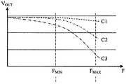
모델의 토폴로지는 1 차 RC 네트워크와 유사하거나, 커패시턴스 (Cd) 와 연관된 저항 (Ria) 은 1 차 저역 통과 필터를 구성한다. 도 4 는, 적용된 주파수의 함수로서, 행 가장자리에 위치된 가압에 대한 제 1 곡선 (C1), 행의 중간에서의 가압에 대한 제 2 곡선 (C2), 행의 단부에서의 가압에 대한 제 3 곡선 (C3) 인, 3 개의 상이한 가압의 포지션들에 대한 행의 출력 신호의 변화를 도시한다. 도 4 의 눈금은 양측 모두에서 로그이다. 그러면, 도 4 에서 보이는 바와 같이, 가압의 포지션이 무엇이든 Ria 의 변화들이 VOUT 의 최소 변화를 야기하는 주파수 (FMIN) 가 존재한다. 역으로, 가압의 포지션에 따라 Ria 의 변화들이 VOUT 의 상당한 감쇠를 야기하는 주파수 (FMAX) 가 존재한다. 따라서, 이러한 주파수 (FMAX) 에서, 이러한 감쇠를 측정함으로써, 그러면 저항 (Ria) 의 값을 확인하고, 결과적으로 행 상의 접촉 지점의 포지션을 결정하기 쉽다.The topology of the model is similar to the primary RC network, or the resistor (Ria ) associated with the capacitance (Cd ) constitutes a first order low pass filter. Fig. 4 shows a first curve C1 for pressurization located at the row edge, a second curve C2 for pressurization in the middle of the row, a third curve C2 for pressurization at the end of the row, Figure 3 shows the change in the output signal of the row for three different pressure positions, curve C3. The scale in FIG. 4 is logarithmic on both sides. Then, as shown in FIG. 4, whatever the position of the pressure, there is a frequency (FMIN ) at which the variations of Ria cause a minimum change of VOUT . Conversely, there is a frequency (FMAX ) at which changes in Ria cause significant attenuation of VOUT depending on the position of the pressure. Thus, at this frequency FMAX , by measuring this attenuation, it is then easy to determine the value of the resistor Ria , and consequently to determine the position of the point of contact on the row.
이러한 측정은 매우 정확할 필요는 없다. 그러나, 2 개의 동시적 가압들의 실제 포지션을 결정하기에는 충분하다. 아시다시피, 대략일지라도, 2 개의 상이한 주파수들에서의 이중 측정을 통해, 가압들의 포지션들, 실제 가압들의 쌍과 실제 가압들의 쌍에 대응하는 고스트 가압들이나 "고스트들" 의 쌍 사이의 불확정성이 올라간다.These measurements need not be very accurate. However, it is sufficient to determine the actual position of the two simultaneous pressures. As you may know, the double measurement at two different frequencies increases the uncertainty between the positions of the pressures, the pair of ghost pressures or "ghosts" corresponding to the pair of actual pressures and the actual presses.
그러나, 사용자의 손가락들의 포지션에서의 불확실성 또는 포지셔닝 오류 중 어느 일방을 낳을 수도 있는 소정의 구성들이 여전히 존재한다. 이러한 구성들 중 하나의 구성은 2 개의 손가락들이 2 개의 이웃 행들 또는 열들을 터치할 경우 일어난다. 이러한 구성은 도 2 에 도시된다. 이 도면에서, 제 1 손가락은 열 (CI) 과 행 (LI) 의 제 1 교차점의 레벨에서 가압하고, 제 2 손가락은 열 (CJ) 과 행 (LI+1) 의 제 2 교차점의 레벨에서 가압한다. 열들의 출력 전압 (VOUT) 은 열들 (CI 및 Cj) 이 가압되었음을 결정하는 것을 가능하게 하는 2 개의 쉽게 식별가능한 스파이크 (spike) 들을 보인다. 한편, 행들의 출력 전압 (VOUT) 은, 전압의 중심 계산들을 이용할지라도, 관련된 행들을 명확하게 식별하는 것을 가능하게 하지 않는 노치 게이트 (notch-gated) 형태를 보인다.However, there are still certain configurations that may result in either uncertainty or positioning errors in the position of the user's fingers. The configuration of one of these configurations occurs when two fingers touch two neighboring rows or columns. This configuration is shown in Fig. In this figure, the first finger presses at the level of the first intersection of row CI and row LI and the second finger presses at the intersection of column CJ and the second intersection of row LI+1 Lt; / RTI > The output voltage VOUT of the columns shows two easily identifiable spikes that make it possible to determine that the columns CI and Cj have been pressed. On the other hand, the output voltage (VOUT ) of the rows shows a notch-gated form that does not make it possible to clearly identify the associated rows, even though they use the center calculations of the voltages.
본 발명에 따른 촉각 디바이스는 이러한 결점들을 보이지 않는다. 본 발명의 물리적 원리는 2 개의 상이한 주파수들에서의 방출 전압들의 이용에 의존한다. 행들 및 열들에 대한 출력 신호들은, 주파수의 함수로서, 행 및 열 상의 가압의 존재뿐만 아니라 이러한 행 및 이러한 열 상의 가압의 포지션을 나타내는 상이한 임피던스들을 가짐이 증명되었다.The haptic device according to the present invention does not exhibit these drawbacks. The physical principles of the present invention depend on the use of emission voltages at two different frequencies. The output signals for rows and columns have been proven to have different impedances as a function of frequency, indicating the presence of pressure on the row and column as well as the position of these rows and this thermal pressure.
이러한 디바이스는 완전히 "듀얼 터치" 이며, 판독 잡음 및 외부의 전자기 방해들에 둔감하고, 마지막으로, 항공학에서 명시된 바와 같은 전자기 방출 표준들과 호환가능하다. 또한, 사용자는 동일한 성능 레벨로 장갑을 낀 손들로 이러한 촉각 표면을 이용할 수 있다.These devices are fully "dual touch ", insensitive to read noise and external electromagnetic disturbances, and finally compatible with electromagnetic emission standards as specified in the aeronautics. In addition, the user can use these tactile surfaces with gloved hands at the same performance level.
좀더 정확하게는, 본 발명의 대상은 복수의 전도 행들 및 전도 열들을 포함하는 매트릭스 터치패드를 포함하는 투영 정전용량 검출을 이용하는 터치스크린 디바이스로서, 상기 패드는 각각의 전도 행 및 각각의 열에 대한 방출 전압들을 발생시키는 전자 제어 수단, 및 각각의 전도 행 및 각각의 열로부터 발생하는 수신 전압들을 수신 및 분석하는 전자 수단에 연결되며,More precisely, an object of the present invention is a touch screen device using projection electrostatic capacitance detection comprising a matrix touch pad including a plurality of conductive rows and conductive columns, said pad comprising a plurality of conductive lines, And an electronic means for receiving and analyzing received voltages arising from each conduction row and each column,
전자 제어 수단은, 각각의 전도 행 및 각각의 열에 대해, 작동 주파수라고 일컬어지는 제 1 주파수에서 방출된 제 1 주기적 방출 전압, 및 제 1 주파수와 상이한, 판별 주파수라고 일컬어지는 제 2 주파수에서 방출된 제 2 주기적 방출 전압을 발생시키며;The electronic control means comprises means for determining, for each conduction row and each column, a first periodic emission voltage emitted at a first frequency, referred to as the operating frequency, and a second periodic emission voltage, emitted at a second frequency, Generating a second periodic emission voltage;
임의의 가압이 없을 시에, 작동 주파수의 값은 이러한 작동 주파수에서 매우 낮은 수신 전압들의 변화들을 야기하도록 충분히 낮고, 판별 주파수의 값은 이러한 판별 주파수에서 행들 및 열들에 따라 주목할 만한 수신 전압들의 변화들을 야기하도록 충분히 높으며;In the absence of any pushing, the value of the operating frequency is low enough to cause very low changes in the received voltages at this operating frequency, and the value of the discrimination frequency is a function of the changes in notable receive voltages High enough to cause it;
수신 및 분석하는 전자 수단 (50) 은, 각각의 행 및 각각의 열에 대해:An electronic means 50 for receiving and analyzing includes, for each row and each column:
- 작동 주파수에서 제 1 수신 전압의 값 및 판별 주파수에서 제 2 수신 전압의 값;The value of the first reception voltage at the operating frequency and the value of the second reception voltage at the discrimination frequency;
- 미리 결정된 값들의 함수로서, 2 개의 수신 전압들의 값들이 터치패드 상의 2 개의 동시적 가압들, 및 관련된 2 개의 행들 및 2 개의 열들 상의 이러한 2 개의 가압들의 위치를 나타내는지를 결정하도록 배열되며;- arranged to determine, as a function of the predetermined values, that the values of the two received voltages represent the two simultaneous presses on the touchpad and the position of these two presses on the associated two rows and two columns;
2 개의 동시적 가압들의 경우에, 제 1 행과 제 1 열의 제 1 교차부에 위치된 제 1 가압, 및 제 2 행과 제 2 열의 제 2 교차점에 위치된 제 2 가압인 2 개의 가압들의 위치결정은:In the case of two simultaneous pressures, the first pressure located at the first intersection of the first row and the first column, and the position of the two presses being the second pressure located at the second intersection of the second row and the second column The decision is:
2 개의 가압들의 전압 변화들에 대응하는 제 1 주파수에 대한 수신 전압들의 "트로프 (trough) 들", 및 제 2 주파수에 대한 수신 전압들의 "트로프들" 을 정확히 나타내는 것을 가능하게 하는 제 1 분석 수단;Troughs " of received voltages for a first frequency corresponding to voltage changes of two pressures, and "troughs" of received voltages for a second frequency, ;
전압 "트로프들" 의 중심들 (barycentres) 을 계산하는 것을 가능하게 하는 제 2 분석 수단;Second analysis means enabling to calculate barycentres of voltage "trops ";
중심들에 대한 지식에 기초하여, 제 1 가압에 대응하는 제 1 행과 제 1 열, 및 제 2 가압에 대응하는 제 2 행과 제 2 열을 결정하는 것을 가능하게 하는 제 3 분석 수단에 의해 수행되는 것을 특징으로 한다.Based on the knowledge of the centers, by means of third analysis means which makes it possible to determine the first row and the first column corresponding to the first pressurization and the second row and the second column corresponding to the second pressurization .
유리하게는, 2 개의 가까운 행들 또는 2 개의 가까운 열들에 대응하는 전압에서의 두 변화들이 하나의 단일 트로프를 형성하는 식으로 제 1 행이 제 2 행의 이웃에 있는 경우 또는, 제 1 열이 제 2 열의 이웃에 있는 경우, 2 개의 가압들의 위치결정은:Advantageously, when the first row is in the neighborhood of the second row, such that two changes in voltage corresponding to two near rows or two near columns form one single trough, In the case of two rows of neighbors, the positioning of the two pressures is:
2 개의 이웃 행들 또는 2 개의 이웃 열들 상의 2 개의 가압들에 대한 전압 변화들에 대응하는 제 1 주파수에 대한 수신 전압들의 "트로프들" 및 제 2 주파수에 대한 수신 전압들의 "트로프들" 을 정확하게 나타내는 것을 가능하게 하는 제 1 분석 수단;&Quot; trops "of received voltages for a first frequency and" troughs "of received voltages for a second frequency corresponding to voltage changes for two presses on two neighboring rows or two neighboring rows A first analysis means for enabling the first analysis means;
2 개의 전압 "트로프들" 의 중심들을 계산하는 것을 가능하게 하는 제 2 분석 수단;Second analysis means enabling to calculate the centers of the two voltage "troughs ";
제 1 가압 또는 제 2 가압에 대응하는 제 1 이웃 행과 제 2 이웃 행 또는 제 1 이웃 열과 제 2 이웃 열을 상기 2 개의 중심들에 대한 지식에 기초하여 결정하는 것을 가능하게 하는 제 3 분석 수단에 의해 수행된다.Third analysis means for enabling determination of a first neighbor row and a second neighbor row or a first neighbor row and a second neighbor row corresponding to a first pressurization or a second pressurization based on knowledge of the two centers, Lt; / RTI >
유리하게는, 수신 전압들을 수신 및 분석하는 전자 수단은 2 개의 동기식 복조기들을 포함하는데, 제 1 복조기는 작동 주파수에서 작동하며, 제 2 복조기는 판별 주파수에서 작동한다.Advantageously, the electronic means for receiving and analyzing receive voltages comprises two synchronous demodulators, wherein the first demodulator operates at an operating frequency and the second demodulator operates at a discriminant frequency.
유리하게는, 수신 및 분석하는 전자 수단은:Advantageously, the electronic means for receiving and analyzing comprises:
- 임의의 가압이 없을 시에 각각의 행 및 각각의 열의 작동 주파수에서의 수신 전압들의 저장된 값들의 테이블;A table of stored values of received voltages at the operating frequency of each row and each column in the absence of any pressure;
- 각각의 행 및 각각의 열에 대해, 측정된 차이들이 관련된 행 또는 열 상의 가압을 나타내는지 여부를 결정하도록 수신 전압들의 측정된 값들과 수신 전압들의 저장된 값들 사이의 차이들을 설정하는 비교 수단을 포함한다.For each row and for each column, comparison means for setting the differences between the measured values of the received voltages and the stored values of the received voltages to determine whether the measured differences represent pressure on the associated row or column .
유리하게는, 작동 주파수는 100 kHz 와 500 kHz 사이에 있고, 판별 주파수는 500 kHz 와 5 MHz 사이에 있다.Advantageously, the operating frequency is between 100 kHz and 500 kHz, and the discrimination frequency is between 500 kHz and 5 MHz.
뒤따르는 비제한적인 설명을 읽을 시에 그리고 첨부된 도면들에 의해 본 발명은 더 잘 이해될 것이고 다른 이점들이 자명해질 것인데:
이미 언급된 도 1 은 2 개의 동시적 가압들에 대한 정전용량 검출의 원리를 도시하며;
이미 언급된 도 2 는 이웃하는 2 개의 행들 또는 2 개의 열들 상의 2 개의 가압들에 대한 정전용량 검출의 문제점을 도시하며;
이미 언급된 도 3 은 터치패드의 행과 열 사이의 교차부 주위의 커패시턴스들 및 전기 저항들의 전기적 다이어그램을 도시하며;
이미 언급된 도 4 는, 2 개의 상이한 주파수들에 대해, 촉감 디바이스에서 가압의 포지션의 함수로서 행 또는 열의 출력 신호의 변화들을 도시하며;
도 5 는 본 발명에 따른 투영 정전용량식 촉감 디바이스의 개략도를 도시하며;
도 6 은 이웃하는 2 개의 행들 또는 2 개의 열들 상의 2 개의 가압들의 검출 및 식별의 원리를 도시한다.Upon reading the following non-limiting description, and by way of the accompanying drawings, the invention will be better understood and other advantages will become apparent:
Figure 1 already mentioned shows the principle of capacitance detection for two simultaneous presses;
Figure 2 already mentioned shows the problem of capacitance detection for two presses on two neighboring rows or two columns;
Figure 3 already mentioned shows an electrical diagram of the capacitances and electrical resistances around the intersection between the rows and columns of the touchpad;
As already mentioned, FIG. 4 shows, for two different frequencies, changes in the output signal of a row or column as a function of the position of the pressure in the tactile device;
Figure 5 shows a schematic diagram of a projection capacitive touch device according to the present invention;
Figure 6 shows the principle of detection and identification of two presses on two neighboring rows or two columns.
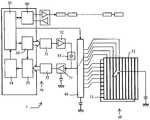
비제한하는 예로서, 도 5 는 본 발명에 따른 투영 정전용량 검출을 이용하는 터치패드를 구비한 디바이스 (1) 를 도시한다. 디바이스 (1) 는 기본적으로 다음을 포함한다:By way of non-limiting example, FIG. 5 shows a
- 제 1 일련의 상호 평행 전도 행들 (11) 을 포함하는 제 1 기판, 및 제 2 일련의 상호 평행 전도 열들 (12) 을 포함하는 제 2 기판을 포함하는 터치패드 (10);A touch pad 10 comprising a first substrate comprising a first series of mutually
- 촉감 디바이스의 동작에 필요한 다양한 방출 신호 및 수신 신호의 제어 및 분석 수단 (20);Means 20 for controlling and analyzing various emission signals and received signals necessary for the operation of the tactile device;
- 디지털-아날로그 변환기 "DAC" (31), 증폭기 (32), 및 주입 커패시터 (33) 를 거쳐 교류 전압들 (VIN) 을 통해 터치패드에 가변 주파수를 공급하는 고주파수 정현파 발생기 (30). 통상, 주파수들은 수백 kHz 와 수 MHz 사이에 있다;- A high
- 다중화기 (40). 다중화기 (40) 는 터치패드 (10) 의 각각의 열 (12) 에 그리고 그 다음에 각각의 행 (11) 에 연속적으로 입력 전압 (VIN) 을 인가하고, 인가된 전압 (VIN) 에 대응하는 각각의 출력 전압 (VOUT) 을 전자 프로세싱 체인 (50) 쪽으로 향하게 한다;- a multiplexer (40). A multiplexer (40) each
- 버퍼 메모리 (51), 아날로그-디지털 변환기 또는 ADC (52), 주파수 발생기 (30) 에 연결된 동기식 복조기 (53), 및 전자 필터링 수단 (54) 을 포함하는 전자 프로세싱 체인 (50). 필터링된 신호들은 분석 수단 (20) 으로 보내진다;An
- 일반적으로 터치패드와 커플링된 뷰잉 디바이스이고 제어, 수정, 또는 인증하고자 하는 정보를 디스플레이하는 외부로의 분석 수단 (20) 에 의해 프로세싱된 신호들의 재송신을 보장하는 송신-수신 수단 (60) 또는 "범용 비동기 송수신기 (Universal Asynchronous Receiver Transmitter)" 를 뜻하는 "UART".Receiving means (60) for ensuring retransmission of signals processed by the analyzing means (20) to the outside, which are generally viewing devices coupled with the touchpad and which display information to be controlled, modified or authenticated, or "UART" which means "Universal Asynchronous Receiver Transmitter".
디바이스는 다음과 같이 동작한다. 정규 모드에서, 패드의 행들 및 열들은 제 1 작동 주파수 (FMIN) 및 제 2 이른바 판별 주파수 (FMAX) 에서 입력 전압 (VIN) 에 의해 영구적으로 그리고 연속적으로 스캐닝된다. 이러한 전압은 수단 (30, 31, 32, 및 33) 으로 구성되는 전자 어셈블리에 의해 발생된다.The device operates as follows. In normal mode, the rows and columns of the pad are scanned permanently and continuously by the input voltage (VIN ) at a first operating frequency (FMIN ) and a second so-called discrimination frequency (FMAX ). This voltage is generated by an electronic assembly consisting of
도 5 에서 손가락으로 상징적으로 나타내어는 가압 중에, 그리고 이러한 가압의 포지션에 따라, 접촉 지점과 접지 사이에 소정의 커패시턴스가 형성되며, 이러한 커패시턴스는 다중화기 (40) 에 행들 및 열들의 저항에 의해 주로 연결된다.5, a predetermined capacitance is formed between the contact point and the ground during the pressing, which is symbolically indicated by a finger, and in accordance with the position of this pressing, and this capacitance is mainly caused by the resistance of the rows and columns in the
이러한 저항식 컴포넌트 및 정전용량식 컴포넌트는 시스템의 전체 임피던스 (Z) 에서의 변화를 야기하고, Z=A+Bj 인 Z.VIN 으로 언급된 바와 같은 출력 신호 (VOUT) 에 영향을 줄 것이다. 신호 (VOUT) 는 그 후에 전자 체인 (50) 에 의해 복조되어 동기식 복조기 (53) 에 의해 Z=A+Bj 이고 j=sin (2π.F.t) 인 실효 값 VOUT=Z.VIN 을 그로부터 추출한다. 동기식 변조는 고 품질 인자를 갖는 대역통과 필터로서 역할을 함으로써 "EMI" 유형의 전자기 방해들을 필터링하는 것을 가능하게 하며, 그렇게 함으로써 다소 선택되지 않은 수동적 필터링들의 이용을 피한다.These resistive and capacitive components will cause a change in the overall impedance Z of the system and will affect the output signal VOUT as referred to as ZVIN , where Z = A + Bj. The signal VOUT is then demodulated by the
적어도 2 개의 측정들이 수행되는데, 하나는 작동 주파수 (FMIN) 에서, 그리고 하나는 판별 주파수 (FMAX) 에서 수행된다. 상당한 치수의 패드들에 있어서는, 여러 판별 주파수들 (FMAX) 을 이용하는 것이 가능하다. 유리하게는, 주파수들 (FMIN 및 FMAX) 은 변조되고 2 개의 동기식 복조기들 (53) 에 의해 별도로 복조됨으로써, 단일 측정으로, 가압의 포지션을 나타내는, 커패시턴스 (C) 및 저항 (R) 의 값들을 입수하는 것을 가능하게 한다. 마지막으로, 복조기 (53) 로부터 발생하는 필터링된 연속 신호가 필터링 수단 (54) 에 의해 필터링된다.At least two measurements are performed, one at the operating frequency (FMIN ) and one at the discrimination frequency (FMAX ). For pads of considerable dimension, it is possible to use several discrimination frequencies (FMAX ). Advantageously, the frequenciesF.sub.MIN andF.sub.MAX are modulated and demodulated separately by two
손의 접근이 없을 시에, 촉감 제어기는 주파수 (FMIN) 에서 패드의 이미지에 영구적으로 영향을 미치고 평균을 하락시켜 그로부터 임피던스들의 정지 테이블을 추론한다. 이러한 이미지는 임피던스들의 순시 값들의 테이블로부터 감해져, 차이들의 테이블을 형성하며, 차이들의 테이블에 기초하여 각각의 교차부 지점이 그 상태에 있다고 하는 것이 가능하다. 이러한 기법은 "Process for operating a capacitive tactile keyboard" 라는 명칭의 특허 제 EP 0 567 364 호에서 부분적으로 설명된다.In the absence of hand access, the tactile controller permanently affects the image of the pad at the frequency (FMIN ) and then subtracts the mean to infer the stop table of impedances from it. This image is subtracted from the table of instantaneous values of impedances to form a table of differences, and it is possible that each intersection point is in that state based on a table of differences. This technique is described in part in patent EP 0 567 364 entitled " Process for operating a capacitive tactile keyboard ".
2 개의 상이한 측정 주파수들의 이용은 상당한 이점을 갖는다. 정렬되지 않은 다수의 가압들의 경우에, 주파수 (FMIN) 에서 그리고 그 다음에 주파수 (FMAX) 에서 4 중의 지점들이 측정된다. 주파수 변화에 뒤이은 신호 변화는 고스트 가압들의 거부를 결정하는데 이용되고, 4 중의 지점들은 다양한 가압들의 좌표를 제공하는 것을 가능하게 한다.The use of two different measurement frequencies has significant advantages. In the case of multiple unadjusted pressures, four points are measured at frequency (FMIN ) and then at frequency (FMAX ). The signal changes following the frequency change are used to determine rejection of the ghost pressures, and the quadruple points enable to provide the coordinates of the various pressures.
가압들의 포지션에 대한 더 많은 세부사항들을 입수하기 위해, 가압들의 위치결정은:In order to obtain more details about the position of the pressures, the positioning of the pressures is:
가압들의 전압 변화들에 대응하는 작동 주파수에 대한 수신 전압들의 "트로프들", 및 판별 주파수에 대한 수신 전압들의 "트로프들" 을 정확히 나타내는 것을 가능하게 하는 제 1 분석 수단; Troughs " of received voltages for an operating frequency corresponding to voltage variations of the pressures, and "troughs" of received voltages for a discriminating frequency;
전압 "트로프들" 의 중심들을 계산하는 것을 가능하게 하는 제 2 분석 수단;Second analysis means enabling to calculate the centers of the voltage "troughs ";
중심들에 대한 지식에 기초하여, 다양한 가압들에 대응하는 행들 및 열들을 결정하는 것을 가능하게 하는 제 3 분석 수단에 의해 수행된다.On the basis of knowledge of the centers, by means of third analysis means which makes it possible to determine the rows and columns corresponding to the various pressures.
예로서, 중심의 결정은 다음의 방식으로 수행된다. 수신 전압들 (VOUT) 의 최초치들 또는 "트로프들" 이 결정된다. 최소치는 특정 행 또는 열에 대응한다. 이 단락 이후부터, 간단함을 위해, 선택적으로, 행들의 수신 전압들의 최초치들만이 관심대상이다. 물론, 방법은 열들에 대해서도 유효하다. 최초치에 대응하는 행 (LMIN) 주위에서, 이러한 행 (LMIN) 의 어느 일측에 위치된 결정된 개수의 행들에 대해, 상기 행들의 중심이 계산되며, 각각의 행에는 상기 행의 출력 전압의 값과 같은 계수가 할당된다. 이러한 중심은 가압 지점의 포지션에 대응한다. 물론, 예를 들어, 전압 최소치 주변의 전압 기울기들을 결정함으로써 기법을 개량하는 것이 가능하다.As an example, the determination of the center is performed in the following manner. Initial values or "troughs" of receive voltages (VOUT ) are determined. The minimum value corresponds to a particular row or column. After this paragraph, for simplicity, alternatively, only the initial values of the received voltages of the rows are of interest. Of course, the method is also valid for columns. Around the line (LMIN) corresponding to the first value, for the lines of a predetermined number located on either side of this line (LMIN), and the center of the row calculation, each row of the output voltage on the line A value equal to the value is assigned. This center corresponds to the position of the pressing point. Of course, it is possible, for example, to improve the technique by determining the voltage gradients around the voltage minimum.
중심 기법은 가압들의 포지션에서의 정확도를 개선시키는 것을 가능하게 한다. 2 개의 상이한 주파수들에서의 측정과 결합되는 경우 다른 이점을 갖는다. 사실, 도 6 에 도시된 바와 같이, 2 개의 동시적 가압들의 경우에서, 제 1 행과 제 1 열의 제 1 교차부에 위치된 제 1 가압 및 제 2 행과 제 2 열의 제 2 교차부에 위치된 제 2 가압의 경우, 및 2 개의 가까운 행들이나 2 개의 가까운 열들에 대응하는 전압에서의 2 개의 변화들이 하나의 단일 전압 트로프를 포함하는 방식으로 제 1 행이 제 2 행의 이웃에 있는 경우나 제 1 열이 제 2 열의 이웃에 있는 경우, 호출된 행들 및 열들을 정확하게 결정하는 것이 가능하다. 사실, 도 6 에서 보이는 바와 같이, 작동 주파수에서, 예를 들어, 2 개의 이웃 행들 (LI 및 LI+1) 상에 위치되는 2 개의 가압들에 대응하는 수신 전압은 호출된 행들을 간단히 결정하는 것을 가능하게 하지 않는 단일 전압 트로트를 제공할 것이다. 2 개의 가압들의 중심을 결정하는 것만이 가능하다. 한편, 판별 주파수에서, 2 개의 가압들 중 하나의 가압에 대응하는 전압 트로프가 감쇠된다. 이제, 제 1 행, 예를 들어, 2 개의 가압들 중 하나의 가압에 대응하는 LI 를 분명하게 결정하는 것을 가능하게 하는 단일 전압 트로프만이 남아 있다. 그 다음에는, 이러한 제 1 가압의 중심 포지션 및 이와 함께 2 개의 가압들의 중심 포지션을 알면, 제 2 가압에 대응하는 제 2 행 (LI+1) 을 결정하는 것이 쉬워진다.The central technique makes it possible to improve the accuracy in the position of the pressures. Have different advantages when combined with measurements at two different frequencies. In fact, as shown in FIG. 6, in the case of two simultaneous pressures, a first pressure located at the first intersection of the first row and first column and a second pressure at the second intersection of the second row and the second column And the first row is in the neighborhood of the second row in such a way that the two changes in voltage corresponding to two near or two near columns include one single voltage trough When the first column is next to the second column, it is possible to determine accurately the called rows and columns. In fact, as shown in FIG. 6, at the operating frequency, for example, the receive voltage corresponding to the two pressures located on the two neighboring rows (LI and LI+1 ) Lt; RTI ID = 0.0 > trot < / RTI > It is only possible to determine the center of the two pressures. On the other hand, at the discrimination frequency, the voltage trough corresponding to one of the two pressures is attenuated. Now, only a single voltage trough remains, which makes it possible to clearly determine the first row, e.g., LI , corresponding to the pressure of one of the two pressures. Then, knowing the center position of this first press and the center position of the two presses together, it becomes easy to determine the second row (LI+1 ) corresponding to the second press.
보이는 바와 같이, 본 발명에 따른 촉감 디바이스에서 구현된 전자 수단은 간단하고, 효과적으로 해결할 수 있게 하는데, 다시 말해, 고스트 감압들의 검출, 가까운 감압들의 검출, 동기식 검출로 인한 외부 전자기 방해들에 대한 둔감성, 및 고조파들 없이 순수 정현파 신호들의 이용을 통한 전자 환경의 방해의 부재라는 투영 정전용량 검출의 주요 문제점들을 효과적으로 해결하는 것을 가능하게 한다.As can be seen, the electronic means embodied in the tactile device according to the invention is simple and effective in that it can be solved, in other words, the detection of ghost decompressions, the detection of nearby decompressions, the insensitivity to external electromagnetic disturbances due to synchronous detection, And the absence of harmonics in the electronic environment through the use of pure sinusoidal signals without harmonics.
Claims (5)
Translated fromKorean상기 전자 제어 수단은, 각각의 전도 행에 대해서 및 각각의 열에 대해서, 작동 주파수라고 일컬어지는 제 1 주파수 (FMIN) 에서 방출되는 제 1 주기적 방출 전압, 및 상기 제 1 주파수와 상이한, 판별 주파수라고 일컬어지는 제 2 주파수 (FMAX) 에서 방출되는 제 2 주기적 방출 전압을 발생시키며,
임의의 가압이 없을 시에, 상기 작동 주파수의 값은 이 작동 주파수에서 상기 수신 전압들의 매우 낮은 변화들을 야기할 만큼 충분히 낮고, 상기 판별 주파수의 값은 이 판별 주파수에서 상기 행들 및 열들에 따라 상기 수신 전압들의 주목할 만한 변화들을 야기할 만큼 충분히 높으며;
상기 수신 및 분석하는 전자 수단 (50) 은, 각각의 행에 대해서 및 각각의 열에 대해서,
- 상기 작동 주파수에서의 제 1 수신 전압의 값, 및 상기 판별 주파수에서의 제 2 수신 전압의 값;
- 미리 결정된 값들의 함수로서, 상기 2 개의 수신 전압들의 값들이 상기 터치패드 상의 2 개의 동시적 가압들 및 관련된 2 개의 행들 및 2 개의 열들 상의 이들 2 개의 가압들의 위치를 나타내는지를 결정하도록 배열되고,
2 개의 동시적 가압들인, 제 1 행과 제 1 열의 제 1 교차부에 위치된 제 1 가압, 및 제 2 행과 제 2 열의 제 2 교차부에 위치된 제 2 가압의 경우에, 상기 2 개의 가압들의 위치결정은,
상기 2 개의 가압들의 전압 변화들에 대응하는 상기 제 1 주파수에 대한 상기 수신 전압들의 "트로프 (trough) 들", 및 상기 제 2 주파수에 대한 상기 수신 전압들의 "트로프들" 을 정확히 나타내는 것을 가능하게 하는 제 1 분석 수단;
상기 전압 "트로프들" 의 중심들을 계산하는 것을 가능하게 하는 제 2 분석 수단;
상기 중심들에 대한 지식에 기초하여, 상기 제 1 가압에 대응하는 상기 제 1 행과 상기 제 1 열, 및 상기 제 2 가압에 대응하는 상기 제 2 행과 상기 제 2 열을 결정하는 것을 가능하게 하는 제 3 분석 수단에 의해 수행되는 것을 특징으로 하는 터치스크린 디바이스.A touch screen device (1) using projection electrostatic capacitance detection comprising a matrix touch pad (10) comprising a plurality of conductive rows (11) and conductive columns (12), the pad comprising: of the discharge voltage to heat the electronic control means 20, and electronic means (50) for receiving and analyzing the received voltages (VOUT) generated from each conductive line, and from each column to generate the (ViN) Lt; / RTI >
The electronic control means comprises a first periodic emission voltage which is emitted at a first frequency (FMIN ), referred to as the operating frequency, for each conduction row and for each column, and a second periodic emission voltage which is different from the first frequency Generates a second periodic emission voltage that is emitted at a second frequency (FMAX )
The value of the operating frequency is low enough to cause very low changes of the received voltages at this operating frequency and the value of the discriminating frequency is determined such that at the discriminating frequency, High enough to cause notable changes in voltages;
The electronic means (50) for receiving and analyzing, for each row and for each column,
A value of a first received voltage at said operating frequency and a value of a second received voltage at said discriminating frequency;
- arranged to determine, as a function of predetermined values, that the values of the two received voltages indicate the position of the two simultaneous presses on the touchpad and the two presses on the two rows and two columns involved,
In the case of a first pressurization located at the first intersection of the first row and the first column and a second pressurization positioned at the second intersection of the second row and the second column, which are two simultaneous pressures, The positioning of the pressures,
Troughs "of the received voltages for the first frequency corresponding to the voltage changes of the two pressures, and" troughs "of the received voltages for the second frequency A first analyzing means for analyzing the image;
Second analysis means enabling to calculate the centers of the voltage "troughs"
Based on knowledge of the centers, it is possible to determine the first row and the first column corresponding to the first pressure and the second row and the second column corresponding to the second pressure Wherein the first analysis means is performed by a second analysis means that performs a second analysis.
2 개의 가까운 행들 또는 2 개의 가까운 열들에 대응하는 전압에서의 2 개의 변화들이 하나의 단일 트로프를 형성하는 식으로, 상기 제 1 행이 상기 제 2 행의 이웃에 있는 경우 또는 상기 제 1 열이 상기 제 2 열의 이웃에 있는 경우, 상기 2 개의 가압들의 위치결정은,
2 개의 이웃 행들 또는 2 개의 이웃 열들 상의 상기 2 개의 가압들에 대한 상기 전압 변화들에 대응하는, 상기 제 1 주파수에 대한 상기 수신 전압들의 "트로프들", 및 상기 제 2 주파수에 대한 상기 수신 전압들의 "트로프들" 을 정확히 나타내는 것을 가능하게 하는 제 1 분석 수단;
2 개의 전압 "트로프들" 의 중심들을 계산하는 것을 가능하게 하는 제 2 분석 수단;
상기 2 개의 중심들에 대한 지식에 기초하여, 상기 제 1 가압 또는 상기 제 2 가압에 대응하는 제 1 이웃 행과 제 2 이웃 행, 또는 제 1 이웃 열과 제 2 이웃 열을 결정하는 것을 가능하게 하는 제 3 분석 수단에 의해 수행되는 것을 특징으로 하는 터치스크린 디바이스.The method according to claim 1,
Wherein two changes in a voltage corresponding to two near rows or two near columns form one single trough wherein the first row is adjacent to the second row, When in the vicinity of the second row,
"Troughs" of the received voltages for the first frequency, corresponding to the voltage changes for the two presses on two neighboring rows or two neighboring rows, &Quot; troughs "of the < / RTI >
Second analysis means enabling to calculate the centers of the two voltage "troughs ";
Based on knowledge of the two centers, to determine a first neighbor row and a second neighbor row, or a first neighbor row and a second neighbor row, corresponding to the first press or the second press Is performed by a third analyzing means.
상기 수신 전압들을 수신 및 분석하는 전자 수단은 2 개의 동기식 복조기들 (53) 인, 상기 작동 주파수에서 작동하는 제 1 복조기, 상기 판별 주파수에서 작동하는 제 2 복조기를 포함하는 것을 특징으로 하는 터치스크린 디바이스.3. The method according to claim 1 or 2,
Characterized in that the electronic means for receiving and analyzing the receive voltages comprises a first demodulator operating at the operating frequency, the second demodulator operating at the discriminating frequency, being two synchronous demodulators (53) .
상기 수신 및 분석하는 전자 수단은,
- 임의의 가압이 없을 시에 각각의 행 및 각각의 열의 상기 작동 주파수에서의 상기 수신 전압들의 저장된 값들에 대한 테이블;
- 각각의 행에 대해서 및 각각의 열에 대해서, 측정된 차이들이 관련된 행 또는 열 상의 가압을 나타내는지 여부를 결정하도록 상기 수신 전압들의 측정된 값들과 상기 수신 전압들의 저장된 값들 사이의 차이들을 설정하는 비교 수단을 포함하는 것을 특징으로 하는 터치스크린 디바이스.4. The method according to any one of claims 1 to 3,
The electronic means for receiving and analyzing comprises:
A table for stored values of the received voltages at the operating frequency of each row and each column in the absence of any pressure;
Comparing for each row and for each column the differences between the measured values of the received voltages and the stored values of the received voltages so as to determine whether the measured differences represent pressure on the associated row or column Wherein the touch screen device comprises a touch screen device.
상기 작동 주파수는 100 kHz 와 500 kHz 사이에 있고, 상기 판별 주파수는 500 kHz 와 5 MHz 사이에 있는 것을 특징으로 하는 터치스크린 디바이스.5. The method according to any one of claims 1 to 4,
Wherein the operating frequency is between 100 kHz and 500 kHz and the discrimination frequency is between 500 kHz and 5 MHz.
Applications Claiming Priority (2)
| Application Number | Priority Date | Filing Date | Title |
|---|---|---|---|
| FR1203298AFR2998989B1 (en) | 2012-12-05 | 2012-12-05 | MULTITOUCHE TOUCH DEVICE WITH MULTIFREQUENCY AND BARCENTRIC CAPACITIVE DETECTION |
| FR1203298 | 2012-12-05 |
Publications (2)
| Publication Number | Publication Date |
|---|---|
| KR20140072821Atrue KR20140072821A (en) | 2014-06-13 |
| KR102201007B1 KR102201007B1 (en) | 2021-01-08 |
Family
ID=47827307
Family Applications (1)
| Application Number | Title | Priority Date | Filing Date |
|---|---|---|---|
| KR1020130150217AExpired - Fee RelatedKR102201007B1 (en) | 2012-12-05 | 2013-12-04 | Multitouch tactile device with multifrequency and barycentric capacitive detection |
Country Status (8)
| Country | Link |
|---|---|
| US (1) | US9453862B2 (en) |
| EP (1) | EP2741188B1 (en) |
| JP (1) | JP6203023B2 (en) |
| KR (1) | KR102201007B1 (en) |
| CN (1) | CN103853407B (en) |
| CA (1) | CA2835587C (en) |
| FR (1) | FR2998989B1 (en) |
| TW (1) | TWI612460B (en) |
Families Citing this family (3)
| Publication number | Priority date | Publication date | Assignee | Title |
|---|---|---|---|---|
| US20190064999A1 (en)* | 2017-08-22 | 2019-02-28 | Stmicroelectronics Asia Pacific Pte Ltd | Multi-frequency scanning of a capacitive panel to address a noise condition |
| FR3086079B1 (en)* | 2018-09-17 | 2021-04-23 | Zodiac Aero Electric | MULTI-KEY TOUCH DEVICE WITH CAPACITIVE DETECTION |
| CN115202504A (en)* | 2022-06-21 | 2022-10-18 | 中国联合网络通信集团有限公司 | Touch identification method and device and storage medium |
Citations (1)
| Publication number | Priority date | Publication date | Assignee | Title |
|---|---|---|---|---|
| EP2196889A2 (en)* | 2008-12-12 | 2010-06-16 | Wacom Co., Ltd. | Architecture and method for multi-aspect touchscreen scanning |
Family Cites Families (20)
| Publication number | Priority date | Publication date | Assignee | Title |
|---|---|---|---|---|
| FR2690544B1 (en) | 1992-04-24 | 1994-06-17 | Sextant Avionique | METHOD FOR OPERATING A CAPACITIVE TOUCH KEYBOARD. |
| US5790107A (en)* | 1995-06-07 | 1998-08-04 | Logitech, Inc. | Touch sensing method and apparatus |
| DE60239504D1 (en)* | 2001-05-08 | 2011-05-05 | Shinetsu Chemical Co | Apparatus and method for making a preform for optical fibers by deposition |
| JP4333428B2 (en)* | 2004-03-22 | 2009-09-16 | 株式会社日立製作所 | Proximity position input device |
| US8482545B2 (en)* | 2008-10-02 | 2013-07-09 | Wacom Co., Ltd. | Combination touch and transducer input system and method |
| TWI403941B (en)* | 2009-08-10 | 2013-08-01 | Innolux Corp | Touch panel display device |
| JP5496735B2 (en)* | 2010-03-30 | 2014-05-21 | 株式会社ワコム | Indicator position detection apparatus and indicator position detection method |
| US8427444B2 (en)* | 2010-04-12 | 2013-04-23 | Silicon Integrated Systems Corp. | Ghost cancellation method for multi-touch sensitive device |
| TWI529681B (en)* | 2010-04-14 | 2016-04-11 | 半導體能源研究所股份有限公司 | Display device and electronic device |
| US8542215B2 (en)* | 2010-04-30 | 2013-09-24 | Microchip Technology Incorporated | Mutual capacitance measurement in a multi-touch input device |
| CN101976139B (en)* | 2010-08-30 | 2012-08-15 | 华映视讯(吴江)有限公司 | Touch panel with function of multi-touch detection and multi-touch detection method |
| TWI408437B (en)* | 2010-09-09 | 2013-09-11 | A liquid crystal display | |
| US8866758B2 (en)* | 2011-02-23 | 2014-10-21 | Honeywell International Inc. | Resistive touch screen displays and systems |
| US8698769B2 (en)* | 2011-08-01 | 2014-04-15 | Sharp Kabushiki Kaisha | Dual mode capacitive touch panel |
| WO2013114793A1 (en)* | 2012-01-30 | 2013-08-08 | パナソニック株式会社 | Tactile-feel presentation device and method for presenting tactile feel |
| US9098153B2 (en)* | 2012-02-01 | 2015-08-04 | Qualcomm Technologies, Inc. | Touch panel excitation using a drive signal having time-varying characteristics |
| TWI456487B (en)* | 2012-04-26 | 2014-10-11 | Acer Inc | Mobile device and gesture determination method |
| US9411928B2 (en)* | 2012-07-17 | 2016-08-09 | Parade Technologies, Ltd. | Discontinuous integration using half periods |
| US9958966B2 (en)* | 2012-10-16 | 2018-05-01 | Atmel Corporation | Active stylus communication and position system |
| US9366708B2 (en)* | 2013-02-06 | 2016-06-14 | Nokia Technologies Oy | Apparatus comprising a flexible substrate and a component supported by the flexible substrate |
- 2012
- 2012-12-05FRFR1203298Apatent/FR2998989B1/ennot_activeExpired - Fee Related
- 2013
- 2013-11-26EPEP13194352.4Apatent/EP2741188B1/enactiveActive
- 2013-11-28TWTW102143571Apatent/TWI612460B/ennot_activeIP Right Cessation
- 2013-12-02CACA2835587Apatent/CA2835587C/enactiveActive
- 2013-12-04KRKR1020130150217Apatent/KR102201007B1/ennot_activeExpired - Fee Related
- 2013-12-04CNCN201310647982.9Apatent/CN103853407B/ennot_activeExpired - Fee Related
- 2013-12-05USUS14/098,407patent/US9453862B2/enactiveActive
- 2013-12-05JPJP2013252121Apatent/JP6203023B2/ennot_activeExpired - Fee Related
Patent Citations (1)
| Publication number | Priority date | Publication date | Assignee | Title |
|---|---|---|---|---|
| EP2196889A2 (en)* | 2008-12-12 | 2010-06-16 | Wacom Co., Ltd. | Architecture and method for multi-aspect touchscreen scanning |
Also Published As
| Publication number | Publication date |
|---|---|
| FR2998989A1 (en) | 2014-06-06 |
| JP6203023B2 (en) | 2017-09-27 |
| US9453862B2 (en) | 2016-09-27 |
| CA2835587A1 (en) | 2014-06-05 |
| EP2741188B1 (en) | 2017-08-23 |
| US20140191769A1 (en) | 2014-07-10 |
| CN103853407A (en) | 2014-06-11 |
| TW201435700A (en) | 2014-09-16 |
| TWI612460B (en) | 2018-01-21 |
| CN103853407B (en) | 2018-05-25 |
| JP2014116005A (en) | 2014-06-26 |
| FR2998989B1 (en) | 2015-01-02 |
| KR102201007B1 (en) | 2021-01-08 |
| CA2835587C (en) | 2020-03-24 |
| EP2741188A1 (en) | 2014-06-11 |
Similar Documents
| Publication | Publication Date | Title |
|---|---|---|
| CN104111763B (en) | The multi-point touch touch sensitive device using multifrequency capacitance detecting of faulty detection device | |
| CN102841714B (en) | Multi-point touch control type touch induction device with multifrequency capacitance detecting | |
| KR102277878B1 (en) | Interleaving sense elements of a capacitive-sense array | |
| US9535598B2 (en) | Hover and touch detection for a digitizer | |
| US9069399B2 (en) | Gain correction for fast panel scanning | |
| US8400422B2 (en) | Method and device for analyzing positions | |
| CN102591515B (en) | Measuring method for the power of multi-mode touch screen device | |
| US9575602B1 (en) | Multi-touch disambiguation | |
| US20110115732A1 (en) | Multimode touchscreen device | |
| US20150070297A1 (en) | Control method for touch panel | |
| CN101414236A (en) | On-screen input image display system | |
| WO2008087638A1 (en) | System and method for calibration of a capacitive touch digitizer system | |
| JP2013152581A (en) | Detector, detection method and display device | |
| WO2007144881A1 (en) | Fingertip touch recognition for a digitizer | |
| WO2017044390A1 (en) | Fingerprint sensor pattern | |
| KR102201007B1 (en) | Multitouch tactile device with multifrequency and barycentric capacitive detection | |
| CN104102397A (en) | Self-contained touch panel |
Legal Events
| Date | Code | Title | Description |
|---|---|---|---|
| PA0109 | Patent application | St.27 status event code:A-0-1-A10-A12-nap-PA0109 | |
| PG1501 | Laying open of application | St.27 status event code:A-1-1-Q10-Q12-nap-PG1501 | |
| R18-X000 | Changes to party contact information recorded | St.27 status event code:A-3-3-R10-R18-oth-X000 | |
| A201 | Request for examination | ||
| P11-X000 | Amendment of application requested | St.27 status event code:A-2-2-P10-P11-nap-X000 | |
| P13-X000 | Application amended | St.27 status event code:A-2-2-P10-P13-nap-X000 | |
| PA0201 | Request for examination | St.27 status event code:A-1-2-D10-D11-exm-PA0201 | |
| E902 | Notification of reason for refusal | ||
| PE0902 | Notice of grounds for rejection | St.27 status event code:A-1-2-D10-D21-exm-PE0902 | |
| P11-X000 | Amendment of application requested | St.27 status event code:A-2-2-P10-P11-nap-X000 | |
| P13-X000 | Application amended | St.27 status event code:A-2-2-P10-P13-nap-X000 | |
| E701 | Decision to grant or registration of patent right | ||
| PE0701 | Decision of registration | St.27 status event code:A-1-2-D10-D22-exm-PE0701 | |
| GRNT | Written decision to grant | ||
| PR0701 | Registration of establishment | St.27 status event code:A-2-4-F10-F11-exm-PR0701 | |
| PR1002 | Payment of registration fee | St.27 status event code:A-2-2-U10-U11-oth-PR1002 Fee payment year number:1 | |
| PG1601 | Publication of registration | St.27 status event code:A-4-4-Q10-Q13-nap-PG1601 | |
| P22-X000 | Classification modified | St.27 status event code:A-4-4-P10-P22-nap-X000 | |
| PC1903 | Unpaid annual fee | St.27 status event code:A-4-4-U10-U13-oth-PC1903 Not in force date:20240106 Payment event data comment text:Termination Category : DEFAULT_OF_REGISTRATION_FEE | |
| R18-X000 | Changes to party contact information recorded | St.27 status event code:A-5-5-R10-R18-oth-X000 | |
| PC1903 | Unpaid annual fee | St.27 status event code:N-4-6-H10-H13-oth-PC1903 Ip right cessation event data comment text:Termination Category : DEFAULT_OF_REGISTRATION_FEE Not in force date:20240106 |