KR20140070126A - Apparatus and method of operating the the illumination apparatus - Google Patents
Apparatus and method of operating the the illumination apparatusDownload PDFInfo
- Publication number
- KR20140070126A KR20140070126AKR1020120138227AKR20120138227AKR20140070126AKR 20140070126 AKR20140070126 AKR 20140070126AKR 1020120138227 AKR1020120138227 AKR 1020120138227AKR 20120138227 AKR20120138227 AKR 20120138227AKR 20140070126 AKR20140070126 AKR 20140070126A
- Authority
- KR
- South Korea
- Prior art keywords
- voltage
- unit
- condition
- dimmer
- output current
- Prior art date
- Legal status (The legal status is an assumption and is not a legal conclusion. Google has not performed a legal analysis and makes no representation as to the accuracy of the status listed.)
- Withdrawn
Links
Images


Classifications
- Y—GENERAL TAGGING OF NEW TECHNOLOGICAL DEVELOPMENTS; GENERAL TAGGING OF CROSS-SECTIONAL TECHNOLOGIES SPANNING OVER SEVERAL SECTIONS OF THE IPC; TECHNICAL SUBJECTS COVERED BY FORMER USPC CROSS-REFERENCE ART COLLECTIONS [XRACs] AND DIGESTS
- Y02—TECHNOLOGIES OR APPLICATIONS FOR MITIGATION OR ADAPTATION AGAINST CLIMATE CHANGE
- Y02B—CLIMATE CHANGE MITIGATION TECHNOLOGIES RELATED TO BUILDINGS, e.g. HOUSING, HOUSE APPLIANCES OR RELATED END-USER APPLICATIONS
- Y02B20/00—Energy efficient lighting technologies, e.g. halogen lamps or gas discharge lamps
- Y02B20/30—Semiconductor lamps, e.g. solid state lamps [SSL] light emitting diodes [LED] or organic LED [OLED]
Landscapes
- Circuit Arrangement For Electric Light Sources In General (AREA)
Abstract
Translated fromKoreanDescription
Translated fromKorean본 발명은 조명 구동 장치에 관한 것으로, 특히 조광기(dimmer)의 동작에 따라 LED(light Emitting Diode)로 공급되는 출력 전류를 제어하는 조명 구동 장치 및 조명 구동 방법에 관한 것이다.BACKGROUND OF THE INVENTION 1. Field of the Invention The present invention relates to an illumination driving apparatus, and more particularly to an illumination driving apparatus and an illumination driving method for controlling an output current supplied to an LED (light emitting diode) according to the operation of a dimmer.
전력변환장치는 전동기, 조명기기 및 각종 통신기기 등에 전력을 공급하기 위하여 사용되며 트랜스포머(Transformer)를 통해 공급되는 전압을 일정 크기의 전압으로 제어하여 상기 장치들을 구동시킨다.The power conversion apparatus is used to supply electric power to an electric motor, a lighting apparatus, various communication apparatuses, and the like, and drives the devices by controlling a voltage supplied through a transformer to a predetermined voltage.
특히, LED(Light Emitting Diode)는 통신기기, TV, 모니터 등의 전자제품에서 여러 가지 신호 전달용으로 사용되고 있는데, 신호 전달용으로 사용되는 LED는 인가되는 전압이 문턱 전압(Threshold)보다 높을 경우 발광하게 되고, 문턱 전압보다 낮을 경우 발광하지 않는 특성을 지니고 있다.In particular, an LED (Light Emitting Diode) is used for various signal transmission in electronic products such as a communication device, a TV, and a monitor. When an applied voltage is higher than a threshold voltage, And does not emit light when it is lower than the threshold voltage.
최근, 조명기기로 사용되는 백열전구보다 조명 효율이 높은 백색 LED가 개발됨에 따라 백열등 또는 형광등과 같은 조명기기를 LED로 대체하기 위한 연구가 진행되고 있으며, 조명용 LED는 저휘도의 신호 전달용 LED와는 달리 LED에 흐르는 전류량이 많고 밝은 빛을 낼 수 있는 고휘도 LED를 사용해야 한다.In recent years, white LEDs with high illumination efficiency have been developed rather than incandescent lamps used as illumination devices, and studies are underway to replace lighting devices such as incandescent lamps or fluorescent lamps with LEDs. Unlike LEDs for signal transmission of low brightness, You should use a high-brightness LED that has a lot of current flowing through the LED and can emit bright light.
이와 같이, 일반 조명 등의 애플리케이션에서 LED를 다수개 직렬연결하여 사용하는 경우, 상기 LED에 일정한 정전류를 제공할 수 있는 정전류 제어가 가능한 구동회로가 필요하다.As described above, when a plurality of LEDs are connected in series in an application such as a general lighting, a driving circuit capable of constant current control capable of providing a constant constant current to the LED is required.
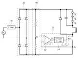
도 1은 종래 기술에 따른 조명 구동 장치를 나타낸 도면이다.1 is a view showing a lighting driving apparatus according to the prior art.
도 1을 참조하면, 종래 기술에 따른 조명 구동 장치는, 상용 교류 전원을 입력받고, 상기 입력된 상용 교류 전원의 위상을 조정하는 조광기(10)와, 상기 조광기(10)를 통해 위상이 조정된 상용 교류 전원을 입력받고, 상기 입력받은 상용 교류 전원을 전파 정류하는 정류기(20)와, 적어도 하나의 스위칭 소자를 포함하며, 상기 스위칭 소자의 스위칭 동작에 의해 부하에 필요한 구동 전원을 공급하는 전력 변환부(30)와, 상기 정류기(20)를 통해 전파 정류된 입력 전압을 감지하는 감지 저항(40)과, 상기 감지 저항(40)을 통해 감지된 전압 레벨과 상기 전력 변환부(30)의 스위칭 소자에 흐르는 전압을 감지하고, 이를 토대로 상기 스위칭 소자의 스위칭 동작을 제어하는 제어부(50)를 포함한다.1, the conventional lighting driving apparatus includes a
제어부(50)는 비교기(52)와 스위칭 제어부(54)를 포함한다.The
비교기(52)는 (+) 단자를 통해 상기 감지 저항(40)에 의해 감지된 입력 전압(Va)을 수신하고, (-) 단자를 통해 상기 스위칭 소자의 드레인-소스 사이에 흐르는 전압을 입력받는다.The
즉, 비교기(52)는 상기 입력 전압(Va)과 드레인-소스 사이에 흐르는 전압 값을 비교하고, 상기 비교 결과를 출력한다.That is, the
스위칭 제어부(54)는 상기 비교기(52)의 비교 결과에 따라 상기 드레인-소스 사이에 흐르는 전압이 상기 입력 전압(Va)보다 높아지는 시점에 상기 스위칭 소자의 턴-오프가 이루어지도록 스위칭 신호를 출력한다.The
이때 스위칭소자의 턴-온시간은 순시적으로 변화되는 입력전압에 따라 동일한 턴-온 시간을 가지게 되고 동일한 턴-온시간에 따라 입력 전류는 입력전압과 같은 sine 전류가 흐르게 되어 고PF 특성을 가지게 된다.At this time, the turn-on time of the switching element has the same turn-on time according to the instantaneous input voltage, and the sine current equal to the input voltage flows in the input current according to the same turn- do.
그러나, 상기와 같은 정전류 제어 방식은 이론상 출력 전류가 일정하도록 되어 있지만, 각종 소자의 오차에 따라 실질적으로 출력되는 전류는 일정하지 않은 문제점이 있다.However, although the output current is theoretically constant in the above-described constant current control method, there is a problem that the output current is not constant in accordance with the error of various devices.
이와 같은 Peak current 제어방식은 Dimmable 제품에서 널리 이용되지만 Dimmable이 아닌 제품에서는 큰 출력전류의 오차에 따라 사용되지 않는 추세이기 때문에 Non-dimmable 제품에서는 널리 사용되지 않고 있다. 따라서 Non-dimmable 제품과 Dimmable 제품을 개발하기 위해서는 특성이 다른 제어IC를 사용하여야 하고 따로 개발되어야 하는 문제점이 발생하게 된다.Such a peak current control method is widely used in dimmable products, but it is not widely used in non-dimmable products because it is not used due to a large output current error in non-dimmable products. Therefore, in order to develop non-dimmable products and dimmable products, control ICs with different characteristics should be used and problems must be developed separately.
만약에 Non-dimmable IC를 사용하여 출력전류를 제어하도록 회로를 조광기(10)를 포함하는 조명 구동 장치에 적용하여 시스템을 구성할 경우 상기 조광기의 동작에 따라 출력 전류는 감소해야 한다. 하지만, 정전류 제어를 위해 보상기를 토대로 출력 전류를 제어하게 되면, 상기 조광기가 동작하여도 계속적인 정전류 제어가 이루어지며, 이에 따라 출력 전류가 감소하지 않는 문제점이 있다.If the system is constructed by applying the circuit to the lighting driving apparatus including the
이에 따라, 조광기의 동작이 필요한 경우, 상기 설명한 바와 같이 피크 전류 제어를 통해 입력 전압의 변화에 따라 피크 전류를 제한하여 출력 전류를 제어하는 방식이 사용된다.Accordingly, when the operation of the dimmer is required, a method of controlling the output current by limiting the peak current according to the change of the input voltage through the peak current control is used as described above.
하지만, 이러한 피크 전류 제어는 감지 저항의 오차 또는 전력 변환부에 사용되는 자기소자의 오차에 따른 전류의 기울기 변화, 그리고 IC 내부의 오차, 입력 전압 변화 등에 따라 일정한 출력 전류의 제어를 하지 못하여 LED수명 또는 PSU 소자들의 수명감소와 같은 문제점이 있다.However, such a peak current control can not control a constant output current due to the error of the sense resistor or the slope of the current due to the error of the magnetic element used in the power conversion unit, the error within the IC, Or a reduction in the life of the PSU elements.
본 발명이 이루고자 하는 기술적 과제는 새로운 방식의 출력 전류 제어 방식을 사용하는 조명 구동 장치 및 조명 구동 방법을 제공하는 것이다.SUMMARY OF THE INVENTION It is an object of the present invention to provide an illumination driving apparatus and an illumination driving method using a novel method of output current control.
본 발명은 입력 전압을 전파 정류하는 정류부, 상기 전파 정류된 입력 전압을 감지하는 감지부, 적어도 하나의 스위칭 소자를 포함하며, 상기 스위칭 소자의 스위칭 동작에 의해 상기 전파 정류된 전압을 소정의 크기로 변환하여 발광소자로 공급하는 전력 변환부, 상기 발광소자에 흐르는 출력 전류를 보상하기 위한 보상 전압을 발생하는 보상부, 상기 정류기에 입력되는 전압의 위상을 제어하는 조광기;According to the present invention, there is provided a switching regulator including a rectifier for full-wave rectifying an input voltage, a sensing unit for sensing the full-wave rectified input voltage, and at least one switching element, A compensator for generating a compensating voltage for compensating an output current flowing through the light emitting element, a dimmer for controlling a phase of a voltage input to the rectifier,
상기 정류기에 입력되는 전압의 제어 여부에 따라 상기 부하로의 출력 전류를 제어하기 위한 조건을 결정하는 조건 결정부 및 상기 조건 결정부의 조건에 따라 상기 감지부의 입력 전압 또는 상기 보상부의 보상 전압 중 어느 하나를 기초로 상기 스위칭 소자를 제어하는 제어부를 포함하는 조명 구동 장치를 포함한다.A condition determining unit for determining a condition for controlling an output current to the load depending on whether a voltage input to the rectifier is controlled and a control unit for controlling either one of an input voltage of the sensing unit and a compensation voltage of the compensating unit And a control unit for controlling the switching device based on the control signal.
또한 본 발명은 입력 전압을 전파 정류하여 감지하는 단계와 상기 감지된 전압의 크기에 따라 부하에 공급되는 출력 전류의 제어를 위한 조건을 결정하는 단계와 상기 결정된 조건에 따라 출력 전류를 공급하기 위한 스위칭 신호를 발생하는 단계 및 상기 스위칭 신호에 따라 입력 전압을 소정의 크기로 변환하여 부하에 출력 전류를 공급하는 단계를 포함하며 상기 결정된 조건은 피크 전류 제어 조건 또는 정전류 제어 조건 중 어느 하나인 조명 구동 방법을 포함한다.According to another aspect of the present invention, there is provided a method of controlling an output current, the method comprising the steps of: detecting and rectifying an input voltage by full-wave rectification; determining a condition for controlling an output current supplied to a load according to a magnitude of the sensed voltage; And a step of supplying an output current to a load by converting an input voltage to a predetermined magnitude according to the switching signal, wherein the determined condition is a peak driving current, which is one of a peak current control condition and a constant current control condition .
본 발명에 따른 실시예에 의하면, 트라이악 조광기(Triac Dimmer)의 선형성과 호환성을 증가시킬 수 있다. 또한 트라이악 조광기가 적용되지 않는 경우 출력 정전류의 제어가 가능하도록 할 수 있다.According to the embodiment of the present invention, the linearity and compatibility of the triac dimmer can be increased. It is also possible to control the output constant current when the triac dimmer is not applied.
즉, 본 발명에서는 트라이악 조광기의 동작에 따라 인덕터에 흐르는 최대 전류를 감소시켜 코어(core)의 포화 문제와 피크(peak) 전류에 따른 다른 소자의 손상을 감소 시킬 수 있고, 출력 전류를 조광기의 동작에 따라 선형적으로 변화 시킬 수 있다.That is, according to the present invention, it is possible to reduce the maximum current flowing through the inductor according to the operation of the triac dimmer, thereby reducing the saturation problem of the core and damaging other elements due to the peak current, It can be changed linearly according to the operation.
도 1은 종래기술에 따른 조명 구동 장치를 나타낸 도면이다.
도 2는 본 발명의 실시 예에 따른 조명 구동 장치를 나타내는 블록도이다.
도 3은 도 2의 조명 구동 장치의 조건 결정부의 상세 구성도이다.
도 4는 조건 결정부와 보상부의 동작상태에 따른 제어부 IC 내부 전압 변화를 나타내는 그래프이다.
도 5는 본 발명의 실시 예에서 조광기가 동작하지 않는 경우 전압 변화를 설명하는 도면이다.
도 6은 본 발명의 실시 예에서 조광기가 동작하는 경우 전압 변화를 설명하는 도면이다.
도 7은 본 발명의 실시 예에 따른 조명 구동 방법을 설명하기 위한 도면이다.1 is a view showing a lighting driving apparatus according to the prior art.
2 is a block diagram showing an illumination driving apparatus according to an embodiment of the present invention.
3 is a detailed configuration diagram of a condition determination unit of the illumination driving apparatus of FIG.
4 is a graph showing changes in the internal voltage of the controller IC according to the operating states of the condition determining unit and the compensating unit.
5 is a view for explaining a voltage change when the dimmer is not operated in the embodiment of the present invention.
6 is a view for explaining a voltage change when the dimmer operates in the embodiment of the present invention.
7 is a view for explaining a lighting driving method according to an embodiment of the present invention.
아래에서는 첨부한 도면을 참고로 하여 본 발명의 실시예에 대하여 본 발명이 속하는 기술 분야에서 통상의 지식을 가진 자가 용이하게 실시할 수 있도록 상세히 설명한다. 그러나 본 발명은 여러 가지 상이한 형태로 구현될 수 있으며 여기에서 설명하는 실시예에 한정되지 않는다. 그리고 도면에서 본 발명을 명확하게 설명하기 위해서 설명과 관계없는 부분은 생략하였으며, 명세서 전체를 통하여 유사한 부분에 대해서는 유사한 도면 부호를 붙였다.Hereinafter, embodiments of the present invention will be described in detail with reference to the accompanying drawings so that those skilled in the art can easily carry out the present invention. The present invention may, however, be embodied in many different forms and should not be construed as limited to the embodiments set forth herein. In order to clearly illustrate the present invention, parts not related to the description are omitted, and similar parts are denoted by like reference characters throughout the specification.
명세서 전체에서, 어떤 부분이 다른 부분과 "연결"되어 있다고 할 때, 이는 "직접적으로 연결"되어 있는 경우뿐 아니라, 그 중간에 다른 소자를 사이에 두고 "전기적으로 연결"되어 있는 경우도 포함한다.Throughout the specification, when a part is referred to as being "connected" to another part, it includes not only "directly connected" but also "electrically connected" with another part in between .
명세서 전체에서, 어떤 부분이 어떤 구성요소를 "포함"한다고 할 때, 이는 특별히 반대되는 기재가 없는 한 다른 구성요소를 제외하는 것이 아니라 다른 구성요소를 더 포함할 수 있는 것을 의미한다. 또한, 명세서에 기재된 "…부", "…기", "모듈" 등의 용어는 적어도 하나의 기능이나 동작을 처리하는 단위를 의미하며, 이는 하드웨어나 소프트웨어 또는 하드웨어 및 소프트웨어의 결합으로 구현될 수 있다.
Throughout the specification, when an element is referred to as "comprising ", it means that it can include other elements as well, without excluding other elements unless specifically stated otherwise. Also, the terms " part, ""module," and " module ", etc. in the specification mean a unit for processing at least one function or operation and may be implemented by hardware or software or a combination of hardware and software have.
이하에서는 도 2 내지 도 7을 참고하여 조광기가 동작하지 않는 상태에서는 LED로의 출력 전류가 기준 전압을 추종하도록 회로를 구성하여 일정한 출력 전류를 얻고, 조광기가 동작하는 상태에서는 조광기에 의해 왜곡되는 입력 전압의 레벨에 따라 출력 전류를 제어할 수 있는 조명 구동 장치 및 이의 조명 구동 방법에 대해 설명하기로 한다.
2 to 7, in a state in which the dimmer is not operated, a circuit is constructed so that the output current to the LED follows the reference voltage to obtain a constant output current. In the state where the dimmer is in operation, A description will be given of an illumination driving apparatus and an illumination driving method capable of controlling the output current according to the level of the driving current.
도 2는 본 발명의 실시 예에 따른 조명 구동 장치를 나타내는 블록도이다.2 is a block diagram showing an illumination driving apparatus according to an embodiment of the present invention.
도 2를 참조하면, 본 발명의 실시 예에 따른 조명 구동 장치는, 교류 전원의 위상을 조정하는 조광기(100)와 교류 전원을 전파 정류하는 정류부(200)와, 발광소자에 필요한 구동 전원을 공급하는 전력 변환부(300)와, 구동 전원에 의해 동작하는 발광소자(400)와, 보상 정보를 출력하는 보상부(500)와, 입력 전압을 감지하는 감지부(700)와 전력 변환부(300)에 스위칭 신호를 출력하는 제어부(600)를 포함한다.
2, the illumination driving apparatus according to the embodiment of the present invention includes a
상기 조광기(100)는 외부로부터 입력되는 조광 신호에 따라 상기 입력된 상용 교류 전원의 위상을 제어하여 출력한다. 상기 조광 신호는 외측의 조도에 따라 발생할 수 있으며, 이에 따라 상기 외측의 조도에 따라 상기 조광기(100)는 상기 입력 교류 전원의 위상을 변환하여 출력할 수 있다.The
상기 정류부(200)는 상기 조광기(100)를 통해 입력되는 교류 전원을 전파 정류하여 출력할 수 있다. 이때 정류부(200)는 하프 브리지 다이오드 또는 풀 브리지 다이오드로 구현가능하며, 이에 대하여 한정하지는 않는다.The
상기 전력변환부(300)는 상기 정류부(200)를 통해 전파 정류된 전원을 공급받고, 상기 전력변환부(300)에 포함되는 스위칭 소자의 스위칭 동작에 따라 상기 전파 정류된 전원의 크기를 변환하여 출력할 수 있다. 이때, 상기 전력 변환부(300)는 절연형 또는 비절연형으로 구성되며, 이에 따라 상기 전파 정류된 전원을 상기 발광소자(400)를 구동시키기 위한 직류 형태의 구동 전류로 변환시켜 출력한다.The
상기 발광소자(400)는 상기 전력 변환부(300)를 통해 출력되는 구동 전류에 의해 구동되다. 이때, 상기 발광소자(400)는 상기 구동 전류에 의해 빛을 발생시키는 LED(light Emitting Diode)일 수 있다.The
상기 보상부(500)는 상기 발광소자(400)로 출력되는 출력 전류를 감지하고, 상기 감지한 출력 전류와 기준 전류를 비교할 수 있다. 또한, 상기 보상부(500)는 상기 출력 전류와 기준 전류에 차이가 발생하는 경우, 상기 출력 전류가 상기 기준 전류를 추종하기 위한 보상 전류를 발생시킬 수 있다. 이때, 상기 보상부(500)는 상기 발생한 보상 전류에 따른 빛을 발생하여, 상기 보상부(500)를 통해 발생한 보상 전류에 따른 정보를 전달하는 광 발생부를 포함한다.The
즉, 상기 보상부(500)는 상기 발광소자(400)의 출력 전류를 감지하고, 상기 감지한 출력 전류와 기준 전류의 차이에 따른 보상 전류에 대응하는 광을 발생하는 광 발생부를 통해 상기 보상 전류에 따른 정보를 제어부(600)로 출력할 수 있다.That is, the compensating
상기 감지부(700)는 복수의 저항을 포함하고, 상기 복수의 저항이 상호 연결되며, 이에 따라 상기 정류기(200)를 통해 전파 정류된 입력 전압의 레벨을 감지할 수 있다.The
상기 조건 결정부(800)는 상기 조광기(100)의 동작 여부에 따라 상기 발광소자(400)로 공급되는 출력 전류의 제어를 위한 조건을 결정할 수 있다.The
바람직하게는, 상기 조건 결정부(800)는 상기 제어부(600)가 상기 조광기(100)의 동작 여부에 따라 상기 보상부(500)를 통해 출력되는 보상 전압 또는 상기 감지부(700)를 통해 감지된 입력 전압 중 어느 하나의 전압 값을 토대로 상기 출력 전류의 제어가 이루어지도록 할 수 있다.Preferably, the
상기 조건 결정부(800)의 동작에 대해서는 하기에서 더욱 상세히 설명하기로 한다.The operation of the
상기 제어부(600)는 상기 보상기(500) 또는 상기 조건 결정부(800)를 통해 결정된 전압을 수신하고, 상기 수신한 전압을 토대로 상기 전력 변환부(300)의 스위칭 소자로 스위칭 신호를 출력하여, 상기 발광소자(400)로 공급되는 출력 전류를 제어할 수 있다.The
즉, 상기 제어부(600)는 상기 수신한 전압에 따라 상기 전력 변환부(300)에 구비된 스위칭 소자의 스위칭 동작을 위한 스위칭 신호를 출력하고, 상기 출력한 스위칭 신호에 의해 상기 전력변환부(300)를 통해 출력되는 전류의 레벨 변경이 이루어지도록 할 수 있다.That is, the
이때, 상기 스위칭 신호는 전력 변환을 위하여 펄스 폭을 가지는데, 상기 조광기(100)가 동작하는 경우에는 상기 감지부(700)에서 감지된 입력 전압에 의해 상기 펄스 폭이 결정되고, 상기 조광기(100)가 동작하지 않는 경우에는 상기 보상부(500)로부터 보상 전압에 의해 상기 펄스 폭이 결정될 수 있다.
In this case, the switching signal has a pulse width for power conversion. When the dimmer 100 operates, the pulse width is determined by the input voltage sensed by the
이하, 상기 조건 결정부(800)에 대하여 설명한다.Hereinafter, the
도 3은 도 2의 조명 구동 장치의 조건 결정부의 상세 구성도이다.3 is a detailed configuration diagram of a condition determination unit of the illumination driving apparatus of FIG.
도 3을 참조하면, 조건 결정부(800)는 비교부(810), 반전부(830), 필터부(850), 다이오드(D1)를 포함한다.3, the
접지가 아니며 상기 비교부(810)와 상기 반전부(830)가 연결되는 노드는 제1 노드이고, 상기 반전부(830)와 상기 필터부(850)가 연결되는 노드는 제2 노드이며, 상기 필터부(850)와 다이오드(D1)이 연결되는 노드는 제3 노드이다.A node to which the
상기 비교부(810)는 OP앰프를 포함하는 레귤레이터(RG1) 또는 비교기를 포함한다.The
상기 비교부(810)는 상기 감지부(700)를 통해 감지된 입력 전압을 기준 전압과 비교하여 기준 전압 보다 높은 전압이 입력되는 경우 로우(low) 신호를 출력하고, 기준 전압 보다 낮은 전압이 입력되는 경우 하이(high) 신호를 출력할 수 있다. 상기 레귤레이터(RG1)에 연결되는 커패시터(C1)는 감지부(700)로부터 입력되는 전압의 잡음을 제거하는 필터 역할을 할 수 있다.상기 반전부(830)는 상기 비교부(810)로부터 입력되는 신호에 따라 트랜지스터(TR1)를 온-오프 하여 상기 비교부(810)의 출력 신호를 반전시킨 신호를 출력할 수 있다.The comparing
일 예로 상기 반전부(830)는 제너 다이오드(Z1), 트랜지스터(TR1), 저항(R1, R2, R3, R4)를 포함한다. 제1 저항(R1)의 일단은 비교부(810)의 출력단과 제너 다이오드(Z1)에 연결되고, 타단은 제4 저항(R4)에 연결될 수 있다. 제4 저항(R4)의 타단은 필터부(850)의 입력단과 트랜지스터(TR1)의 컬렉터에 연결될 수 있다. 제너 다이오드(Z1)의 타단은 제2 저항(R2)에 정방향 연결되고, 제2 저항(R2)의 타단은 제3 저항(R3)의 일단과 트랜지스터(TR1)의 베이스에 연결될 수 있다. 제3 저항(R3)의 타단과 트랜지스터(TR1)의 이미터는 접지에 연결될 수 있다. 다만, 반전부(830)의 구성은 이에 한정하지 않는다.For example, the inverting
상기 필터부(850)는 상기 반전부(830)의 출력을 필터링하여 저장할 수 있다. 상기 필터부는 저항(R5)과 커패시터(C2)를 포함한다.The
또한 다른 실시예로 인덕터와 커패시터를 이용하여 필터부를 구성할 수 있다.In another embodiment, the filter unit may be formed using an inductor and a capacitor.
상기 다이오드(D1)에는 상기 조광기(100)의 동작 여부에 따라 선택적으로 전류가 흐르거나 흐르지 않는다.A current does not flow or flow selectively in the diode D1 depending on whether the dimmer 100 is operated or not.
상기 조광기(100)가 동작하여, 상기 조광기(100)에 의해 입력전압이 왜곡됨에 따라 상기 입력 전압의 평균 레벨이 감소하는 경우, 상기 비교부(810)는 하이 신호를 출력하여 비교부 제1 노드 전압(Va)은 고전압 출력 구간이 늘어난다. 즉 듀티비가 증가한다. 제1 노드의 듀티비가 증가하는 경우 트랜지스터(TR1)의 턴-온 구간 또한 늘어나게 된다. 따라서 제2 노드 전압(Vb)은 상기 비교부(810)의 반전 신호인 로우 신호가 출력되는 구간이 늘어난다. 즉, 듀티비는 감소하게 된다. 제2 노드퓨의 듀티비가 감소하면, 상기 필터부(850)에도 상대적으로 낮은 평균 전압이 저장된다. 상기 필터부(850)에 낮은 평균 전압이 저장되는 경우 다이오드(D1)의 캐소드에는 상대적으로 낮은 전압이 걸리게 되고, 보상부(500)에 비해 낮은 전압이 인가되기 때문에 다이오드(D1)는 도통 상태가 되어 상기 제어부(600)로 입력 신호를 출력할 수 있다.When the dimmer 100 operates and the average level of the input voltage decreases as the input voltage is distorted by the dimmer 100, the
반대로 상기 조광기(100)가 동작하지 않는 경우 상기 입력 전압의 평균 레벨은 높은 상태이고, 이 경우 상기 비교부(810)는 로우 신호를 출력하여 제1 노드 전압(Va)은 저전압이 출력되는 구간이 늘어난다. 즉, 듀티비가 감소하게 된다. 제1 노드의 듀티비가 낮아지는 경우, 트랜지스터(TR1)의 턴-온 구간 또한 감소하게 된다. 따라서 제2 노드 전압(Vb)은 상기 비교부(810)의 반전 신호인 하이 신호가 출력되는 구간이 늘어난다. 즉, 듀티비가 증가하게 된다. 제2 노드 듀티비가 증가하면 상기 필터부(850)에도 상대적으로 높은 평균 전압이 저장된다. 상기 필터부(850)에 높은 평균 전압이 저장되는 경우 상기 다이오드(D1)의 캐소드에는 상대적으로 높은 전압이 걸리게되고, 보상부(500)에 비해 높은 전압이 인가되기 때문에 다이오드(D1)는 턴-오프 상태가 되어 상기 제어부(600)로 입력 신호를 출력할 수 없다.
In contrast, when the dimmer 100 is not operated, the average level of the input voltage is high. In this case, the
도 4는 조건 결정부(800)와 보상부(500)의 동작상태에 따른 제어부(600) IC 내부 전압 변화를 나타내는 그래프이다.4 is a graph showing changes in the internal voltage of the
그래프의 가로축은 조광기(100)의 동작에 따른 입력 전압의 phase cut의 크기를 나타내고, 세로축은 제어부 IC 내부 전압(Vcomp) 변화에 따른 발광 소자(400)의로의 출력 전류(output currrent)의 변화를 나타낸다.The abscissa of the graph represents the magnitude of the phase cut of the input voltage according to the operation of the dimmer 100 and the ordinate represents the change of the output currrent to the
제어부(600)의 내부 전압(Vcomp)이 높아지게 되면 출력 전류(oupput current)는 증가하게 되고, 제어부의 전압(Vcomp)이 낮아지게 되면 출력 전류(output current)는 감소하게 된다.The output current increases when the internal voltage Vcomp of the
즉, 조광기(100)의 동작에 따라 조건 결정부(800)의 전압이 낮아지게 되고, 제어부(600)에 조건 결정부에서 출력되는 낮은 전압이 인가되고, 조광기(100)의 phase cut 레벨에 따라 출력 전류가 가변하게 된다.
That is, the voltage of the
상기 조건 결정부(800)는 상기 조광기의 동작에 따라 다이오드(D1)가 온 - 오프되도록 조절하여, 조광기(100)가 동작하는 경우에는 입력 전압을 기준으로 발광소자(400)에 공급되는 출력 전류를 제어하는 피크 전류 제어 방식을 선택하고, 조광기가 동작하지 않는 경우에는 보상부(500)의 보상 전압을 기준으로 발광소자(400)에 공급되는 출력 전류를 제어하는 정전류 제어 방식으로 출력 전류를 제어할 수 있도록 조건을 결정하는 역할을 할 수 있다.
The
이하에서 조광기(100)의 동작 여부에 따른 조건 결정부(800)의 주요 소자에 걸리는 전압 변화에 대하여 설명한다.Hereinafter, the voltage change applied to the main elements of the
도 5는 본 발명의 실시 예에서 조광기가 동작하지 않는 경우 전압 변화를 설명하는 도면이고, 도 6은 본 발명의 실시 예에서 조광기가 동작하는 경우 전압 변화를 설명하는 도면이다.FIG. 5 is a view for explaining a voltage change when the dimmer is not operated in an embodiment of the present invention, and FIG. 6 is a view for explaining a voltage change when the dimmer operates in the embodiment of the present invention.
도 5를 참고하면, 조광기(100)가 동작하지 않는 경우 감지 전압(Vac)은 정류부(200)에서 전파 정류된 전류가 감지부(700)에서 적당한 크기로 변환되어, 소정의 크기로 변환된 전파 정류 전압이 걸린다.5, when the dimmer 100 does not operate, the sensing voltage Vac is a current that is obtained by converting the current rectified by the rectifying
조건 결정부(800)의 비교부(810)는 기준 전압과 상기 감지 전압(Vac)을 비교하여, 기준 전압 보다 감지 전압(Vac)이 작은 경우에는 제1 노드 전압(Va)으로 하이(high) 신호를 출력하고, 기준 전압 보다 감지 전압(Vac)이 더 큰 경우에는 제1 노드 전압(Va)으로 로우(low) 신호를 출력한다.The comparing
상기 반전부(830)는 상기 제1 노드 전압(Va) 신호를 반전시킨다. 즉, 제1 노드에 하이 신호가 출력되는 경우 제2 노드에는 low 신호가 출력되고, 제1 노드에 로우 신호가 출력되는 경우 제2 노드에는 하이 신호가 출력된다.The inverting
필터부(850)의 커패시터(C2)에 걸리는 제3 노드 전압(Vc)은 제2 노드에 하이 신호가 걸리는 구간이 길어지면 평균 전압이 상승하고, 제2 노드에 로우 신호가 걸리는 구간이 길어지면 평균 전압이 하강한다.The third node voltage Vc applied to the capacitor C2 of the
상기와 같은 과정에 따라 조광기가 동작하지 않는 경우 상기 비교부(810)에서 기준전압 보다 감지 전압(Vac)의 크기가 더 큰 구간의 시간이 더 길기 때문에 제1 노드 전압(Va)는 로우 신호가 출력되는 시간이 길고, 제2 노드 전압(Vb)는 하이 신호가 출력되는 구간이 길다. 즉, 제1 노드의 듀티비는 감소하고, 제2 노드의 듀티비는 증가한다. 또한, 제2 노드의 듀티비가 증가하면, 필터부(850)에 에너지가 저장되는 시간이 길어져 제3 노드에 높은 평균 전압이 출력된다.When the dimmer is not operated according to the above procedure, since the duration of the sensing voltage Vac is longer than the reference voltage in the
이 경우 조건 결정부(800)의 다이오드(D1)에는 캐소드의 높은 전압으로 인하여 다이오드(D1)가 턴-오프상태가 되고, 제어부(600)는 보상부(500)의 보상 신호에 따라 회로의 동작을 제어할 수 있다.
In this case, the diode D1 of the
한편, 도 6를 참조하면, 조광기(100)가 동작하는 경우 조광기의 동작에 따라 위상이 왜곡된 감지 전압(Vac)이 걸린다.Referring to FIG. 6, when the dimmer 100 operates, a sensing voltage Vac having a distorted phase is applied according to the operation of the dimmer.
조건 결정부(800)의 비교부(810)는 기준 전압과 상기 감지 전압(Vac)을 비교하여, 기준 전압 보다 감지 전압(Vac)이 작은 경우, 제1 노드 전압(va)은 하이(high) 신호가 출력되고, 기준 전압 보다 감지 전압(Vac)이 더 큰 경우, 제1 노드 전압(Va)은 로우(low) 신호가 출력된다.The
상기 반전부(830)는 상기 제1 노드 전압(Va) 신호를 반전시킨다. 즉, 제1 노드 전압(Va)이 하이 신호인 경우 제2 노드 전압(Vb)은 로우(low) 신호가 되고, 제1 노드 전압(Va)이 로우 신호인 경우 제2 노드 전압(Vb)는 하이 신호가 된다.The inverting
필터부(850)의 커패시터(C2)에 걸리는 제3 노드 전압(Vc)은 제2 노드 전압(Vb)이 하이 신호인 경우 전압이 상승하고, 제2 노드 전압(Vb)이 로우 신호인 경우 전압이 하강한다.The third node voltage Vc applied to the capacitor C2 of the
상기와 같은 과정에 따라 조광기가 동작하는 경우 상기 비교부(810)에서 기준 전압 보다 감지 전압(Vac)의 크기가 더 큰 구간이 짧아졌다. 따라서 도 5에서 조광기가 동작하지 않는 경우와 비교하여 볼 때 제1 노드 전압(Va)은 하이 신호가 출력되는 시간이 길어지고, 제2 노드 전압(Vb)은 로우 신호가 출력되는 구간이 길어졌다. 즉, 제1 노드의 듀티비는 증가하고, 제2 노드의 듀티비는 감소하였다. 또한, 제2 노드의 듀티비가 감소하기 때문에 필터부(850)에 에너지가 저장되는 시간이 줄어들어 제3 노드에도 상대적으로 낮은 평균 전압이 걸리게 된다.When the dimmer operates according to the above-described procedure, the interval in which the magnitude of the sensing voltage (Vac) is larger than the reference voltage in the
이 경우 조건 결정부(800)의 다이오드(D1)에는 캐소드의 낮은 전압으로 인하여 다이오드(D1)가 턴 온(turn on) 상태가 되고, 제어부(600)는 조건 결정부(800)로부터 출력되는 신호에 따라 회로의 동작을 제어할 수 있다.
In this case, the diode D1 of the
도 7은 본 발명의 실시 예에 따른 조명 구동 방법을 설명하기 위한 도면이다.7 is a view for explaining a lighting driving method according to an embodiment of the present invention.
먼저 입력 전압을 전파 정류하여 감지하는 단계(S10)는 입력 전압을 정류부(200)에서 전파 정류하고 전파 정류 된 전압을 감지부(700)에서 감지한다.In operation S10, the input voltage is rectified by the
상기 감지된 전압의 크기에 따라 발광소자에 공급되는 출력 전류의 제어를 위한 조건을 결정하는 단계(S20)는 비교부(810)에서 상기 감지 전압과 기준 전압을 비교하는 단계와 반전부(830)에서 비교부(810)의 출력을 반전시키는 단계와 상기 반전 된 출력을 필터링 및 저장하는 단계 그리고 상기 저장된 전압 값에 따라 다이오드가 턴-온 또는 턴-오프되는 단계를 포함한다.The step S20 of determining a condition for controlling the output current supplied to the light emitting device according to the detected voltage level may include comparing the sensing voltage with the reference voltage in the comparing
상기 다이오드(D1)가 턴-온 또는 턴-오프되는 단계는 조광기(100)가 동작하는 경우 다이오드가 턴-온되고, 조광기(100)가 동작하지 않는 경우 다이오드(D1)가 턴-오프된다.The diode D1 is turned on or off when the dimmer 100 is operated and the diode D1 is turned off when the dimmer 100 is not operating.
상기 조건을 결정하는 단계(S20)에서 조광기(100)가 동작하는 경우, 결정된 조건에 따라 출력 전류를 공급하기 위한 스위칭 신호를 발생하는 단계(S30)는 제어부(600)에서 상기 감지된 전압의 크기에 따라 출력 전류를 제어할 수 있는 스위칭 신호를 출력한다.The step S30 of generating the switching signal for supplying the output current in accordance with the determined condition when the dimmer 100 operates in the step of determining the condition S20 is performed by the
스위칭 신호에 따라 입력 전압을 소정의 크기로 변환하여 발광소자에 출력 전류를 공급하는 단계(S40)는 전력 변환부(300)에서 제어부(600)의 스위칭 신호를 입력 받아 상기 발광소자에 공급되는 출력 전류를 감소시킨다.The step S40 of converting the input voltage to a predetermined magnitude according to the switching signal to supply the output current to the light emitting device includes receiving the switching signal of the
한편, 상기 조건을 결정하는 단계(S20)에서 조광기(100)가 동작하지 않는 경우, 보상부(500)의 출력에 따라 스위칭 신호를 발생하는 단계(S50)로 진행한다. 상기 보상부(500)의 출력에 따라 스위칭 신호를 발생하는 단계(S50)는 제어부가 발광소자(400)에 실제 흐르는 출력 전류가 기 설정된 기준 전류를 추종하도록 하기 위한 보상부(500)의 보상 전압을 입력 받아 스위칭 신호의 펄스 폭을 결정하는 단계이다.On the other hand, if the dimmer 100 does not operate in the step of determining the condition (S20), the process proceeds to a step S50 of generating a switching signal in accordance with the output of the compensating
스위칭 신호에 따라 입력 전압을 소정의 크기로 변환하여 발광소자(400)에 출력 전류를 공급하는 단계(S60)는 전력 변환부(300)에서 제어부(600)의 스위칭 신호를 입력 받아 상기 발광소자(400)에 공급되는 출력 전류가 일정할 수 있도록 출력 전류를 공급한다.
The step S60 of converting the input voltage to a predetermined magnitude according to the switching signal to supply the output current to the
이상에서 본 발명의 실시 예에 대하여 상세하게 설명하였지만 본 발명의 권리범위는 이에 한정되는 것은 아니고 다음의 청구범위에서 정의하고 있는 본 발명의 기본 개념을 이용한 당업자의 여러 변형 및 개량 형태 또한 본 발명의 권리범위에 속하는 것이다.While the present invention has been particularly shown and described with reference to exemplary embodiments thereof, it is to be understood that the invention is not limited to the disclosed exemplary embodiments, It belongs to the scope of right.
100 : 조광기
200 : 정류부
300 : 전력 변환부
400 : 발광소자
500 : 보상부
600 : 제어부
700 : 감지부
800 : 조건 결정부
810 : 비교부
830 : 반전부
850 : 필터부100: dimmer
200: rectification part
300: power conversion section
400: light emitting element
500:
600:
700:
800: condition determining unit
810:
830: Inverse
850:
Claims (19)
Translated fromKorean상기 전파 정류된 입력 전압을 감지하는 감지부;
적어도 하나의 스위칭 소자를 포함하며, 상기 스위칭 소자의 스위칭 동작에 의해 상기 전파 정류된 전압을 소정의 크기로 변환하여 발광소자로 공급하는 전력 변환부;
상기 발광소자에 흐르는 출력 전류를 보상하기 위한 보상 전압을 발생하는 보상부;
상기 정류기에 입력되는 전압의 위상을 제어하는 조광기;
상기 정류기에 입력되는 전압의 제어 여부에 따라 상기 발광소자로의 출력 전류를 제어하기 위한 조건을 결정하는 조건 결정부; 및
상기 조건 결정부의 조건에 따라 상기 감지부의 입력 전압 또는 상기 보상부의 보상 전압 중 어느 하나를 기초로 상기 스위칭 소자를 제어하는 제어부를 포함하는 조명 구동 장치.A rectifying section for full-wave rectifying an input voltage;
A sensing unit for sensing the full-wave rectified input voltage;
A power conversion unit including at least one switching device, for converting the full-wave rectified voltage into a predetermined voltage by a switching operation of the switching device and supplying the voltage to the light emitting device;
A compensation unit for generating a compensation voltage for compensating an output current flowing to the light emitting device;
A dimmer for controlling a phase of a voltage input to the rectifier;
A condition determining unit that determines a condition for controlling an output current to the light emitting device according to whether a voltage input to the rectifier is controlled; And
And a control unit for controlling the switching device on the basis of either the input voltage of the sensing unit or the compensation voltage of the compensating unit according to the condition of the condition determining unit.
상기 제어부는,
상기 조건 결정부를 통해 결정된 조건에 따라 제1 전류 제어 방식 또는 제2 전류 제어 방식 중 어느 하나의 방식을 이용하여, 상기 발광소자로 공급되는 출력 전류를 제어하는 조명 구동 장치.The method according to claim 1,
Wherein,
And controls an output current supplied to the light emitting element using one of a first current control method and a second current control method according to a condition determined through the condition determination unit.
상기 제1 전류 제어 방식은 상기 감지부를 통해 감지된 입력 전압을 기준으로 하는 피크 전류 제어 방식이고,
상기 제2 전류 제어 방식은 상기 보상부를 통해 발생한 보상 전압을 기준으로 하는 정전류 제어 방식인 조명 구동 장치.3. The method of claim 2,
The first current control scheme is a peak current control scheme based on an input voltage sensed through the sensing unit,
Wherein the second current control scheme is a constant current control scheme based on a compensation voltage generated through the compensation unit.
상기 조건 결정부는,
상기 조광기의 동작 여부에 따라 상기 조건을 결정하는 조명 구동 장치.The method according to claim 1,
Wherein the condition determining unit determines,
And determines the condition according to whether the dimmer is operated or not.
상기 조광기가 동작하는 경우 제1 전류 제어 방식으로 출력 전류를 제어하고,
상기 조광기가 동작하지 않는 경우 제2 전류 제어 방식으로 출력 전류를 제어하는 조명 구동 장치.The method of claim 3,
A first current control method for controlling the output current when the dimmer operates,
And the output current is controlled by a second current control method when the dimmer is not operated.
상기 조건 결정부는,
상기 조광기가 동작하는 경우 상기 감지부를 통해 감지된 입력 전압을 제어부로 출력하고,
상기 조광기가 동작하지 않는 경우 상기 제어부와 개방되어, 상기 보상부의 보상 전압이 제어부로 입력되는 조명 구동 장치.The method according to claim 1,
Wherein the condition determining unit determines,
And outputs the detected input voltage to the controller when the dimmer operates,
And the compensation voltage of the compensation unit is input to the control unit when the dimmer is not operated.
상기 조건 결정부는
상기 감지부를 통해 감지된 입력 전압 및 기준 전압을 비교하는 비교부,
상기 비교부의 출력을 반전 시키는 반전부,
상기 반전부의 출력을 필터링하여 저장하는 필터부, 그리고
상기 필터부의 전압 레벨에 따라 동작하는 다이오드를 포함하는 조명 구동 장치.The method according to claim 1,
The condition determiner
A comparing unit comparing the input voltage and the reference voltage sensed by the sensing unit,
An inverting unit for inverting an output of the comparing unit,
A filter unit for filtering and storing the output of the inverting unit, and
And a diode that operates in accordance with a voltage level of the filter unit.
상기 비교부는 기준 전압과 특정 전압을 비교하여 신호를 발생시키는 소자를 포함하는 조명 구동 장치.8. The method of claim 7,
Wherein the comparator includes an element for comparing a reference voltage with a specific voltage to generate a signal.
상기 신호를 발생시키는 소자는,
OP-AMP, 비교기 또는 션트레귤레이터 중 적어도 하나를 포함하는 조명 구동 장치.9. The method of claim 8,
Wherein the signal generating element comprises:
OP-AMP, a comparator, or a shunt regulator.
상기 필터부는 저항과 커패시터를 포함하는 조명 구동 장치.8. The method of claim 7,
Wherein the filter portion includes a resistor and a capacitor.
상기 필터부는 인덕터와 커패시터를 포함하는 조명 구동 장치.8. The method of claim 7,
Wherein the filter section includes an inductor and a capacitor.
상기 다이오드는
상기 조광기가 동작하는 경우 턴-온되고,
상기 조광기가 동작하지 않는 경우 턴-오프되는 조명 구동 장치.8. The method of claim 7,
The diode
When the dimmer is in operation,
And is turned off when the dimmer is not operated.
상기 감지부는 복수의 저항을 포함하는 조명 구동 장치.The method according to claim 1,
Wherein the sensing unit includes a plurality of resistors.
상기 감지된 전압의 크기에 따라 발광소자에 공급되는 출력 전류의 제어를 위한 조건을 결정하는 단계;
상기 결정된 조건에 따라 출력 전류를 공급하기 위한 스위칭 신호를 발생하는 단계; 및
상기 스위칭 신호에 따라 입력 전압을 소정의 크기로 변환하여 발광소자에 출력 전류를 공급하는 단계를 포함하며,
상기 결정된 조건은 피크 전류 제어 조건 또는 정전류 제어 조건 중 어느 하나인 조명 구동 방법.Wave rectifying and detecting an input voltage;
Determining a condition for controlling an output current supplied to the light emitting device according to a magnitude of the sensed voltage;
Generating a switching signal for supplying an output current according to the determined condition; And
And converting the input voltage into a predetermined voltage according to the switching signal to supply an output current to the light emitting device,
Wherein the determined condition is any one of a peak current control condition and a constant current control condition.
상기 출력 전류의 제어를 위한 조건을 결정하는 단계는,
비교부에서 상기 감지 전압과 기준 전압을 비교하는 단계,
반전부에서 비교부의 출력을 반전시키는 단계,
상기 반전 된 출력을 필터링 및 저장하는 단계, 그리고
상기 저장된 전압 값에 따라 다이오드가 턴-온 또는 턴-오프되는 단계를 포함하는 조명 구동 방법.15. The method of claim 14,
Wherein the step of determining a condition for controlling the output current comprises:
Comparing the sensing voltage with a reference voltage in a comparator,
Inverting the output of the comparator in the inverting section,
Filtering and storing the inverted output, and
And turning the diode on or off according to the stored voltage value.
다이오드가 턴-온 또는 턴-오프되는 단계는,
조광기가 동작하는 경우 다이오드가 턴-온되고, 조광기가 동작하지 않는 경우 다이오드가 턴-오프되는 조명 구동 방법.16. The method of claim 15,
The step of the diode being turned on or off,
Wherein the diode is turned on when the dimmer is operating and the diode is turned off when the dimmer is not operating.
상기 피크 전류 제어 조건은 조광기가 동작하는 경우 상기 감지된 전압의 크기에 따라 출력 전류를 제어하기 위한 조건이고,
상기 정전류 제어 조건은 상기 조광기가 동작하지 않는 경우 보상부의 보상 전압으로 출력 전류를 제어하기 위한 조건인 조명 구동 방법.15. The method of claim 14,
The peak current control condition is a condition for controlling the output current according to the magnitude of the sensed voltage when the dimmer operates,
Wherein the constant current control condition is a condition for controlling an output current to a compensation voltage of the compensator when the dimmer is not operated.
상기 발광소자에 출력 전류를 공급하는 단계는,
상기 조광기가 동작하는 경우,
상기 조광기에 의해 왜곡된 입력 전압에 따라 상기 발광소자에 공급되는 출력 전류를 감소시키는 단계를 포함하고,
상기 조광기가 동작하지 않는 경우,
상기 보상 전압에 따라 기설정된 기준 전류를 추종하도록 일정한 출력 전류를 공급하는 단계를 포함하는 조명 구동 방법.18. The method of claim 17,
Wherein the step of supplying an output current to the light-
When the dimmer operates,
And reducing an output current supplied to the light emitting element according to an input voltage distorted by the dimmer,
When the dimmer does not operate,
And supplying a constant output current to follow a preset reference current according to the compensation voltage.
스위칭 신호를 발생하는 단계는,
상기 피크 전류 제어 조건에서는 왜곡된 입력 전압에 의해 상기 스위칭 신호의 펄스 폭이 결정되고,
상기 정전류 제어 조건에서는 보상 전압에 의해 상기 스위칭 신호의 펄스 폭이 결정되는 조명 구동 방법.15. The method of claim 14,
The step of generating a switching signal comprises:
The pulse width of the switching signal is determined by the distorted input voltage in the peak current control condition,
Wherein the pulse width of the switching signal is determined by the compensation voltage under the constant current control condition.
Priority Applications (1)
| Application Number | Priority Date | Filing Date | Title |
|---|---|---|---|
| KR1020120138227AKR20140070126A (en) | 2012-11-30 | 2012-11-30 | Apparatus and method of operating the the illumination apparatus |
Applications Claiming Priority (1)
| Application Number | Priority Date | Filing Date | Title |
|---|---|---|---|
| KR1020120138227AKR20140070126A (en) | 2012-11-30 | 2012-11-30 | Apparatus and method of operating the the illumination apparatus |
Publications (1)
| Publication Number | Publication Date |
|---|---|
| KR20140070126Atrue KR20140070126A (en) | 2014-06-10 |
Family
ID=51125095
Family Applications (1)
| Application Number | Title | Priority Date | Filing Date |
|---|---|---|---|
| KR1020120138227AWithdrawnKR20140070126A (en) | 2012-11-30 | 2012-11-30 | Apparatus and method of operating the the illumination apparatus |
Country Status (1)
| Country | Link |
|---|---|
| KR (1) | KR20140070126A (en) |
Cited By (4)
| Publication number | Priority date | Publication date | Assignee | Title |
|---|---|---|---|---|
| KR20160032367A (en)* | 2014-09-15 | 2016-03-24 | 매그나칩 반도체 유한회사 | Circuit and method of driving light apparatus |
| CN106211442A (en)* | 2016-07-19 | 2016-12-07 | 华中科技大学 | An Adaptive Primary Side Peak Current Compensation Method for LED Drivers |
| CN110177410A (en)* | 2019-05-24 | 2019-08-27 | 深圳市晟碟半导体有限公司 | A kind of LED light adjusting circuit, dimming device and light-dimming method |
| WO2022075798A1 (en)* | 2020-10-08 | 2022-04-14 | 엘지이노텍 주식회사 | Light driving apparatus and method for driving same |
- 2012
- 2012-11-30KRKR1020120138227Apatent/KR20140070126A/ennot_activeWithdrawn
Cited By (7)
| Publication number | Priority date | Publication date | Assignee | Title |
|---|---|---|---|---|
| KR20160032367A (en)* | 2014-09-15 | 2016-03-24 | 매그나칩 반도체 유한회사 | Circuit and method of driving light apparatus |
| CN106211442A (en)* | 2016-07-19 | 2016-12-07 | 华中科技大学 | An Adaptive Primary Side Peak Current Compensation Method for LED Drivers |
| CN106211442B (en)* | 2016-07-19 | 2018-09-18 | 华中科技大学 | A kind of adaptive primary side peak current compensation method of LED driver |
| CN110177410A (en)* | 2019-05-24 | 2019-08-27 | 深圳市晟碟半导体有限公司 | A kind of LED light adjusting circuit, dimming device and light-dimming method |
| WO2022075798A1 (en)* | 2020-10-08 | 2022-04-14 | 엘지이노텍 주식회사 | Light driving apparatus and method for driving same |
| JP2023545428A (en)* | 2020-10-08 | 2023-10-30 | エルジー イノテック カンパニー リミテッド | Lighting driving device and its driving method |
| US12238834B2 (en) | 2020-10-08 | 2025-02-25 | Lg Innotek Co., Ltd. | Light driving apparatus and method for driving same |
Similar Documents
| Publication | Publication Date | Title |
|---|---|---|
| US8598802B2 (en) | Triac dimmer compatible WLED driving circuit and method thereof | |
| US8222825B2 (en) | Dimmer for a light emitting device | |
| US9300215B2 (en) | Dimmable LED power supply with power factor control | |
| US8339053B2 (en) | LED dimming apparatus | |
| US8044600B2 (en) | Brightness-adjustable LED driving circuit | |
| TWI420972B (en) | Circuits for driving light source, methods for controlling dimming of light source, driving systems, and controllers for regulating brightness of light source | |
| US9089020B2 (en) | Dimming signal generation device and illumination control system using same | |
| US20130127356A1 (en) | Led driving power supply apparatus and led lighting apparatus | |
| US9072138B2 (en) | Color correcting device driver | |
| US8575853B2 (en) | System and method for supplying constant power to luminuous loads | |
| US20120319610A1 (en) | Led lighting apparatus | |
| US10028340B2 (en) | Wall mounted AC to DC converter gang box | |
| JP2012529124A (en) | Apparatus, method, and system for supplying AC line power to a lighting device | |
| US10306717B1 (en) | Flicker-free LED driving apparatus and voltage regulating method thereof | |
| US7230391B2 (en) | Multi-phase input dimming ballast with flyback converter and method therefor | |
| US11602020B2 (en) | Dimming signal generation circuit, dimming signal generation method and LED driver | |
| KR20140070126A (en) | Apparatus and method of operating the the illumination apparatus | |
| CN205793540U (en) | The three-in-one light adjusting circuit of LED in lamp control system | |
| JP6603763B2 (en) | Lighting system | |
| KR20140079041A (en) | Light driving apparatus and driving method thereof | |
| JP2008052994A (en) | Lighting device and control circuit | |
| US8773046B2 (en) | Driving circuit having voltage dividing circuits and coupling circuit for controlling duty cycle of transistor and related circuit driving method thereof | |
| TWI407833B (en) | Driver circuit and method for driving load circuit | |
| JP2014131420A (en) | Power-supply device | |
| KR101705831B1 (en) | Apparatus for dimming light emmiting devices |
Legal Events
| Date | Code | Title | Description |
|---|---|---|---|
| PA0109 | Patent application | Patent event code:PA01091R01D Comment text:Patent Application Patent event date:20121130 | |
| PG1501 | Laying open of application | ||
| PC1203 | Withdrawal of no request for examination | ||
| WITN | Application deemed withdrawn, e.g. because no request for examination was filed or no examination fee was paid |