KR20140063251A - Power supply device for camera device in mobile terminal - Google Patents
Power supply device for camera device in mobile terminalDownload PDFInfo
- Publication number
- KR20140063251A KR20140063251AKR1020120130401AKR20120130401AKR20140063251AKR 20140063251 AKR20140063251 AKR 20140063251AKR 1020120130401 AKR1020120130401 AKR 1020120130401AKR 20120130401 AKR20120130401 AKR 20120130401AKR 20140063251 AKR20140063251 AKR 20140063251A
- Authority
- KR
- South Korea
- Prior art keywords
- power
- input
- power supply
- core
- sensor
- Prior art date
- Legal status (The legal status is an assumption and is not a legal conclusion. Google has not performed a legal analysis and makes no representation as to the accuracy of the status listed.)
- Withdrawn
Links
Images


Classifications
- G—PHYSICS
- G06—COMPUTING OR CALCULATING; COUNTING
- G06F—ELECTRIC DIGITAL DATA PROCESSING
- G06F1/00—Details not covered by groups G06F3/00 - G06F13/00 and G06F21/00
- G06F1/26—Power supply means, e.g. regulation thereof
- H—ELECTRICITY
- H04—ELECTRIC COMMUNICATION TECHNIQUE
- H04N—PICTORIAL COMMUNICATION, e.g. TELEVISION
- H04N23/00—Cameras or camera modules comprising electronic image sensors; Control thereof
- H04N23/60—Control of cameras or camera modules
- H04N23/65—Control of camera operation in relation to power supply
- H04N23/651—Control of camera operation in relation to power supply for reducing power consumption by affecting camera operations, e.g. sleep mode, hibernation mode or power off of selective parts of the camera
- H—ELECTRICITY
- H02—GENERATION; CONVERSION OR DISTRIBUTION OF ELECTRIC POWER
- H02M—APPARATUS FOR CONVERSION BETWEEN AC AND AC, BETWEEN AC AND DC, OR BETWEEN DC AND DC, AND FOR USE WITH MAINS OR SIMILAR POWER SUPPLY SYSTEMS; CONVERSION OF DC OR AC INPUT POWER INTO SURGE OUTPUT POWER; CONTROL OR REGULATION THEREOF
- H02M1/00—Details of apparatus for conversion
- H02M1/0045—Converters combining the concepts of switch-mode regulation and linear regulation, e.g. linear pre-regulator to switching converter, linear and switching converter in parallel, same converter or same transistor operating either in linear or switching mode
- H—ELECTRICITY
- H02—GENERATION; CONVERSION OR DISTRIBUTION OF ELECTRIC POWER
- H02M—APPARATUS FOR CONVERSION BETWEEN AC AND AC, BETWEEN AC AND DC, OR BETWEEN DC AND DC, AND FOR USE WITH MAINS OR SIMILAR POWER SUPPLY SYSTEMS; CONVERSION OF DC OR AC INPUT POWER INTO SURGE OUTPUT POWER; CONTROL OR REGULATION THEREOF
- H02M1/00—Details of apparatus for conversion
- H02M1/0067—Converter structures employing plural converter units, other than for parallel operation of the units on a single load
- H02M1/008—Plural converter units for generating at two or more independent and non-parallel outputs, e.g. systems with plural point of load switching regulators
Landscapes
- Engineering & Computer Science (AREA)
- Multimedia (AREA)
- Signal Processing (AREA)
- Theoretical Computer Science (AREA)
- Physics & Mathematics (AREA)
- General Engineering & Computer Science (AREA)
- General Physics & Mathematics (AREA)
- Charge And Discharge Circuits For Batteries Or The Like (AREA)
- Power Engineering (AREA)
Abstract
Translated fromKoreanDescription
Translated fromKorean본 발명은 카메라 디바이스를 포함하는 모바일 단말에 관한 것으로, 특히 카메라 디바이스에 동작 전원들을 공급하는 카메라 디바이스 전원 공급 장치에 관한 것이다.
The present invention relates to a mobile terminal comprising a camera device, and more particularly to a camera device power supply for supplying operating power to a camera device.
모바일 전화기, 태블릿 컴퓨터, 스마트 폰과 같은 각종 모바일 단말은 카메라 디바이스를 장착하고 있다. 특히 근래에는 모바일 단말이 전면 카메라와 후면 카메라 같은 다수의 카메라 디바이스들을 장착하고 있는 것이 일반화되어 있다. 통상적으로 전면 카메라는 모바일 단말의 전면에 설치되어 모바일 단말의 전방 촬영에 사용되는 카메라를 가리키고, 후면 카메라는 모바일 단말의 후면에 설치되어 모바일 단말의 후방 촬영에 사용되는 카메라를 가리킨다.Various mobile terminals such as mobile phones, tablet computers and smart phones are equipped with camera devices. Particularly in recent years, it has become common that a mobile terminal is equipped with a plurality of camera devices such as a front camera and a rear camera. Typically, the front camera refers to a camera installed on the front of a mobile terminal to be used for taking a front view of the mobile terminal, and the rear view camera refers to a camera installed on a rear face of the mobile terminal and used for rearview of the mobile terminal.
통상적인 모바일 단말의 전면 카메라 배치 예를 보인 도 1을 참조하면, 전면 카메라(102)는 모바일 단말(100)의 전면에 있는 디스플레이(104)의 우측 상부에 배치된다. 이와 달리 전면 카메라(102)는 모바일 단말(100)의 전면에서 우측 상부 이외의 다른 위치에 배치될 수도 있다.1, which is an example of a front camera arrangement of a typical mobile terminal, a
한편 모바일 단말에서 필요한 각종 전원은 파워 컨버터에 의해 배터리 전원으로부터 생성된다. 모바일 단말에 있어서 파워 컨버터로는 LDO(low dropout), 스위칭 레귤레이터가 주로 사용된다. 파워 컨버터의 종류에 따라 전압, 전류 및 효율이 달라진다.On the other hand, various power supplies required by the mobile terminal are generated from the battery power by the power converter. As a power converter in a mobile terminal, a low dropout (LDO) and a switching regulator are mainly used. Voltage, current and efficiency vary depending on the type of power converter.
LDO는 입력 전압과 출력 전압의 차이만큼 입력 전원의 전압을 강하시켜 열로 발산하는 리니어 레귤레이터이다. LDO의 효율은 출력 전압을 입력 전압으로 나눈 값으로 표현된다. 그러므로 LDO의 효율은 입력 전압과 출력 전압의 차이가 클수록 떨어지게 된다. 스위칭 레귤레이터는 스위칭 소자에 의해 입력 직류 전원을 반복적으로 단속하면서 인덕터에 에너지를 저장하는 방식에 의해 출력 전원으로 변환한다. 스위칭 레귤레이터의 효율은 출력 전압 및 전류의 곱을 입력 전압 및 전류의 곱으로 나눈 값으로 표현된다. 스위칭 레귤레이터는 이론상 손실이 없고 열도 발생하지 않는다. 이에 따라 스위칭 레귤레이터는 이상적인 소자를 가정한다면 100% 효율을 가지지만, 실제 소자의 경우에는 일반적으로 80%~95% 정도의 효율을 가진다.The LDO is a linear regulator that dissipates heat by dropping the voltage of the input power supply by the difference between the input voltage and the output voltage. The efficiency of the LDO is expressed as the output voltage divided by the input voltage. Therefore, the efficiency of the LDO decreases as the difference between the input voltage and the output voltage increases. The switching regulator converts the input DC power to the output power by repeatedly interrupting the input DC power by a switching element and storing energy in the inductor. The efficiency of a switching regulator is expressed as the product of the output voltage and current divided by the product of the input voltage and current. The switching regulator is theoretically lossless and does not generate heat. Thus, a switching regulator assumes 100% efficiency assuming an ideal device, but is typically 80% to 95% efficient for an actual device.
모바일 단말에 있어서 배터리 전원으로부터 전면 카메라의 동작 전원을 생성하는 전원 공급 장치는 파워 컨버터로서 LDO를 사용하여 왔다. 전형적으로 전면 카메라는 셀프 카메라 기능이나 화상 통화 기능에 사용되어 왔다. 이에 따라 전면 카메라는 VT(Video Telephony) 카메라라고도 불린다. 이처럼 전면 카메라는 일부 한정된 상황에서만 사용될 뿐이므로, 모바일 단말에서 카메라 디바이스 전원 공급 장치의 소모 전류의 비중이 높지 않았다. 이에 따라 전면 카메라의 동작 전원을 생성하기 위한 파워 컨버터로서 LDO를 사용하여도 모바일 단말 전체의 소모 전류에 미치는 영향이 크지 않았다.A power supply for generating operating power of a front camera from battery power in a mobile terminal has used an LDO as a power converter. Typically, the front-facing camera has been used for self-camera functions and video calling functions. Accordingly, the front side camera is also called a video telephony (VT) camera. Since the front camera is used only in a limited situation, the consumption of the camera device power supply in the mobile terminal is not high. As a result, even if the LDO is used as a power converter for generating the operation power of the front camera, the power consumption of the entire mobile terminal is not significantly affected.
하지만 최근 모바일 단말에 있어서 제스처(gesture) 인식 기능이 중요하게 대두되면서 전면 카메라가 모바일 단말의 각종 사용 모드에서 동작되는 경우가 많아지고 있다. 특히 모바일 단말이 아이들 모드인 경우에도 제스처 인식 등을 위해 전면 카메라 사용이 증가하고 있다. 이에 따라 모바일 단말에 있어서 전면 카메라로 인한 소모 전류의 비중도 높아지고 있다. 따라서 전면 카메라와 같은 카메라 디바이스로 인한 소모 전류 감소가 필요한 상황이다.
In recent years, gesture recognition function has become important in mobile terminals, and front cameras are increasingly used in various modes of use of mobile terminals. Especially, when the mobile terminal is in the idle mode, the use of the front camera for gesture recognition is increasing. Accordingly, the proportion of the consumed current due to the front camera in the mobile terminal is also increasing. Therefore, it is necessary to reduce the consumption current due to the camera device such as the front camera.
따라서 본 발명은 모바일 단말에서 카메라 디바이스로 인한 소모 전류를 감소시킬 수 있는 카메라 디바이스 전원 공급 장치를 제공한다.Accordingly, the present invention provides a camera device power supply device capable of reducing the consumption current due to a camera device in a mobile terminal.
본 발명은 모바일 단말에서 카메라 디바이스로 인한 소모 전류를 최적화할 수 있는 카메라 디바이스 전원 공급 장치를 제공한다.
The present invention provides a camera device power supply capable of optimizing the consumption current due to a camera device in a mobile terminal.
본 발명의 일 측면에 따라, 다수의 동작 전원들에 의해 동작하는 카메라 디바이스를 포함하는 모바일 단말의 카메라 디바이스 전원 공급 장치는, 상기 동작 전원들 중 소비 전력이 가장 큰 동작 전원을 상기 모바일 단말의 배터리 전원으로부터 생성하는 스위칭 레귤레이터를 포함한다.According to an aspect of the present invention, a camera device power supply device of a mobile terminal including a camera device operated by a plurality of operation power supplies supplies power to the mobile terminal, And a switching regulator that is generated from a power source.
본 발명의 다른 측면에 따라, 다수의 동작 전원들에 의해 동작하는 카메라 디바이스를 포함하는 모바일 단말의 카메라 디바이스 전원 공급 장치는, 상기 모바일 단말의 배터리 전원으로부터 서브 전원을 생성하는 스위칭 레귤레이터와, 상기 서브 전원으로부터 상기 동작 전원들 중 코어 전원을 생성하는 LDO와, 상기 서브 전원으로부터 상기 동작 전원들 중 입출력 전원을 생성하는 LDO를 포함하고, 상기 서브 전원이 상기 동작 전원들 중 센서 전원으로 공급된다.According to another aspect of the present invention, a camera device power supply device of a mobile terminal including a camera device operated by a plurality of operation power supplies includes a switching regulator for generating a sub power source from battery power of the mobile terminal, An LDO for generating a core power of the operation power supplies from a power supply and an LDO for generating an input / output power supply among the operation power supplies from the sub power supply, and the sub power supply is supplied to the sensor power supply among the operation power supplies.
본 발명의 또 다른 측면에 따라, 다수의 동작 전원들에 의해 동작하는 카메라 디바이스를 포함하는 모바일 단말의 카메라 디바이스 전원 공급 장치는, 상기 모바일 단말의 배터리 전원으로부터 서브 전원을 생성하는 스위칭 레귤레이터를 포함하고, 상기 서브 전원이 상기 동작 전원들 중 코어 전원, 센서 전원, 입출력 전원으로 공급된다.According to another aspect of the present invention, a camera device power supply of a mobile terminal including a camera device operated by a plurality of operating power supplies includes a switching regulator for generating sub power from battery power of the mobile terminal , And the sub power is supplied to the core power supply, the sensor power supply, and the input / output power supply among the operating power supplies.
본 발명의 또 다른 측면에 따라, 다수의 동작 전원들에 의해 동작하는 카메라 디바이스를 포함하는 모바일 단말의 카메라 디바이스 전원 공급 장치는, 상기 모바일 단말의 배터리 전원으로부터 서브 전원을 생성하는 스위칭 레귤레이터와, 상기 서브 전원으로부터 상기 동작 전원들 중 코어 전원을 생성하는 LDO와, 상기 배터리 전원으로부터 상기 동작 전원들 중 센서 전원을 생성하는 LDO를 포함하고, 상기 서브 전원이 상기 동작 전원들 중 입출력 전원으로 공급된다.According to another aspect of the present invention, there is provided a camera device power supply device of a mobile terminal including a camera device operated by a plurality of operating power supplies, the device comprising: a switching regulator for generating a sub power source from battery power of the mobile terminal; An LDO for generating a core power of the operation power supplies from a sub power supply and an LDO for generating a sensor power supply among the operation power supplies from the battery power supply, and the sub power supply is supplied to the input / output power supply among the operation power supplies.
본 발명의 또 다른 측면에 따라, 다수의 동작 전원들에 의해 동작하는 카메라 디바이스를 포함하는 모바일 단말의 카메라 디바이스 전원 공급 장치는, 상기 모바일 단말의 배터리 전원으로부터 서브 전원을 생성하는 스위칭 레귤레이터와, 상기 배터리 전원으로부터 상기 동작 전원들 중 센서 전원을 생성하는 LDO를 포함하고, 상기 서브 전원이 상기 동작 전원들 중 코어 전원, 입출력 전원으로 공급된다.According to another aspect of the present invention, there is provided a camera device power supply device of a mobile terminal including a camera device operated by a plurality of operating power supplies, the device comprising: a switching regulator for generating a sub power source from battery power of the mobile terminal; And an LDO that generates a sensor power of the operating power supplies from the battery power, and the sub power is supplied to the core power supply and the input / output power supply of the operating power supplies.
본 발명의 또 다른 측면에 따라, 다수의 동작 전원들에 의해 동작하는 카메라 디바이스를 포함하는 모바일 단말의 카메라 디바이스 전원 공급 장치는, 상기 모바일 단말의 배터리 전원으로부터 상기 동작 전원들 중 코어 전원을 생성하는 스위칭 레귤레이터와, 상기 배터리 전원으로부터 서브 전원을 생성하는 스위칭 레귤레이터를 포함하고, 상기 서브 전원이 상기 동작 전원들 중 센서 전원, 입출력 전원으로 공급된다.According to another aspect of the present invention, a camera device power supply of a mobile terminal including a camera device that is operated by a plurality of operating power supplies includes a power supply for generating a core power of the operating power supplies from the battery power of the mobile terminal A switching regulator and a switching regulator for generating a sub power supply from the battery power supply, wherein the sub power supply is supplied to the sensor power supply and the input / output power supply among the operating power supplies.
본 발명의 또 다른 측면에 따라, 다수의 동작 전원들에 의해 동작하는 카메라 디바이스를 포함하는 모바일 단말의 카메라 디바이스 전원 공급 장치는, 상기 모바일 단말의 배터리 전원으로부터 상기 동작 전원들 중 코어 전원을 생성하는 스위칭 레귤레이터와, 상기 배터리 전원으로부터 서브 전원을 생성하는 스위칭 레귤레이터와, 상기 서브 전원으로부터 상기 동작 전원들 중 입출력 전원을 생성하는 LDO를 포함하고, 상기 서브 전원이 상기 동작 전원들 중 센서 전원으로 공급된다.
According to another aspect of the present invention, a camera device power supply of a mobile terminal including a camera device that is operated by a plurality of operating power supplies includes a power supply for generating a core power of the operating power supplies from the battery power of the mobile terminal A switching regulator for generating a sub power source from the battery power source; and an LDO for generating an input / output power source among the operating power sources from the sub power source, wherein the sub power source is supplied to the sensor power source .
본 발명에 따르면 모바일 단말에서 카메라 디바이스의 동작 전원들 중에 적어도 일부 또는 부분적으로 스위칭 레귤레이터에 의해 생성함으로써 카메라 디바이스로 인한 소모 전류를 감소시킬 수 있으며 카메라 디바이스 전원 공급 장치를 최적화할 수 있다.
According to the present invention, it is possible to reduce the consumption current due to the camera device and optimize the camera device power supply by generating at least partly or partially by the switching regulator among the operating power sources of the camera device in the mobile terminal.
도 1은 통상적인 모바일 단말의 전면 카메라 배치 예시도,
도 2는 본 발명의 제1 실시 예에 따른 모바일 단말의 블록도,
도 3은 본 발명의 제2 실시 예에 따른 모바일 단말의 블록도,
도 4는 본 발명의 제3 실시 예에 따른 모바일 단말의 블록도,
도 5는 본 발명의 제4 실시 예에 따른 모바일 단말의 블록도,
도 6은 본 발명의 제5 실시 예에 따른 모바일 단말의 블록도,
도 7은 본 발명의 제6 실시 예에 따른 모바일 단말의 블록도,
도 8은 본 발명의 제7 실시 예에 따른 모바일 단말의 블록도,
도 9는 본 발명의 제8 실시 예에 따른 모바일 단말의 블록도,
도 10은 본 발명의 제9 실시 예에 따른 모바일 단말의 블록도,
도 11은 본 발명의 제10 실시 예에 따른 모바일 단말의 블록도,
도 12는 본 발명의 제11 실시 예에 따른 모바일 단말의 블록도,
도 13은 본 발명의 제12 실시 예에 따른 모바일 단말의 블록도,
도 14는 전면 카메라 파워 시퀀스 예시도.1 is a diagram illustrating an example of a conventional front-side camera placement of a mobile terminal,
2 is a block diagram of a mobile terminal according to a first embodiment of the present invention;
3 is a block diagram of a mobile terminal according to a second embodiment of the present invention;
4 is a block diagram of a mobile terminal according to a third embodiment of the present invention;
5 is a block diagram of a mobile terminal according to a fourth embodiment of the present invention;
6 is a block diagram of a mobile terminal according to a fifth embodiment of the present invention;
7 is a block diagram of a mobile terminal according to a sixth embodiment of the present invention;
8 is a block diagram of a mobile terminal according to a seventh embodiment of the present invention;
9 is a block diagram of a mobile terminal according to an eighth embodiment of the present invention;
10 is a block diagram of a mobile terminal according to a ninth embodiment of the present invention;
11 is a block diagram of a mobile terminal according to a tenth embodiment of the present invention;
12 is a block diagram of a mobile terminal according to an eleventh embodiment of the present invention;
13 is a block diagram of a mobile terminal according to a twelfth embodiment of the present invention;
14 illustrates an example of a front camera power sequence.
이하 본 발명의 실시 예들을 첨부 도면을 참조하여 상세히 설명한다. 첨부된 도면에 대한 참조 부호를 사용한 이하의 설명은 특허청구범위와 그에 균등한 것들에 의해 정의된 것과 같은 본 발명의 실시 예의 포괄적인 이해를 돕기 위한 것이다. 또한 도면들 중에 동일한 구성요소들에는 가능한 한 동일한 참조 부호를 부여하였다.Hereinafter, embodiments of the present invention will be described in detail with reference to the accompanying drawings. BRIEF DESCRIPTION OF THE DRAWINGS The following description, taken with reference to the accompanying drawings, is intended to assist a comprehensive understanding of the embodiments of the invention as defined by the claims and their equivalents. Also, in the drawings, the same components are denoted by the same reference symbols as possible.
또한 본 발명의 실시 예들의 이해를 돕기 위해 여러 가지 특정 상세들이 포함되지만, 이는 단지 예시에 관한 것으로 간주되어야 한다. 따라서 당업자라면 본 발명의 범위 및 정신을 벗어나지 않으면서 이하에 설명된 실시 예들의 여러 가지 변경 및 수정을 할 수 있음을 인식할 것이다. 또한 공지 기능이나 구성에 관한 설명은 명확성과 간결성을 위해 생략될 수 있다.In addition, various specific details are included to facilitate understanding of the embodiments of the present invention, but it should be considered only as an example. Accordingly, those skilled in the art will recognize that various changes and modifications of the embodiments described below may be made without departing from the spirit and scope of the invention. In addition, descriptions of known functions or configurations may be omitted for clarity and brevity.
이하의 설명 및 특허청구범위에서 사용된 용어들 및 단어들은 서지적인 의미에 한정되지 않으며, 단지 본 발명의 명확하고 일관된 이해가 가능하도록 발명자에 의해 사용된 것이다. 그러므로 그 정의는 본 명세서 전반에 걸친 내용을 토대로 내려져야 할 것이다.The terms and words used in the following description and the claims are not intended to be limited to bibliographic meanings, but merely those used by the inventors to enable a clear and consistent understanding of the invention. Therefore, the definition should be based on the contents throughout this specification.
이하에서 모바일 단말에서 전면 카메라의 동작 전원을 생성하는 전원 공급 장치의 예를 들어 본 발명의 실시 예들을 설명한다. 하지만 유사한 기술적 배경을 가지는 다른 장치들에도 본 발명의 실시 예가 적용될 수 있다. 또한 본 발명의 실시 예들은 본 발명이 속하는 기술 분야에서 통상의 지식을 가진 자에 의해 본 발명의 범위를 벗어나지 않는 범위에서 일부 변형을 통해 다른 장치들에도 적용될 수 있다. 즉, 본 발명은 모바일 단말에 있어서 전면 카메라 이외의 다른 카메라 디바이스를 위한 전원 공급 장치에도 마찬가지로 적용될 수 있다.Hereinafter, embodiments of the present invention will be described as an example of a power supply for generating operating power of a front camera in a mobile terminal. However, embodiments of the present invention may be applied to other devices having similar technical backgrounds. Further, the embodiments of the present invention can be applied to other apparatuses by a person having ordinary skill in the art to which the present invention belongs, through some modifications without departing from the scope of the present invention. That is, the present invention can be similarly applied to a power supply device for a camera device other than a front camera in a mobile terminal.
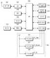
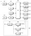
도 2는 본 발명의 제1 실시 예에 따른 모바일 단말의 블록 구성도이다. 도 2의 모바일 단말은 본 발명의 제1 실시 예에 따른 전원 공급 장치(224)를 포함한다.2 is a block diagram of a mobile terminal according to a first embodiment of the present invention. The mobile terminal of FIG. 2 includes a
도 2를 참조하면, AP(Application Processor)(200)는 모바일 단말의 주제어부로서 모바일 단말의 전반적인 기능을 제어 및 처리한다. RF(Radio Frequency) 블록(202)은 이동 통신 기지국으로부터 RF 신호를 수신하여 베이스밴드 신호로 변환하여 CP(Communication Processor)(204)에 제공하며, CP(204)에서 처리된 베이스밴드 신호를 RF 신호로 변환하여 기지국으로 송신한다. CP(204)는 이동 통신을 위한 각종 처리를 한다. WC(Wireless Connectivity)(206)는 Wi-Fi(Wireless Fidelity), BT(Bluetooth), NFC(Near Field Communication)와 같은 통신 기능을 제공한다.Referring to FIG. 2, an application processor (AP) 200 controls and processes an overall function of a mobile terminal as a main part of a mobile terminal. The RF (Radio Frequency) block 202 receives an RF signal from a mobile communication base station, converts the baseband signal into a baseband signal, provides the baseband signal to a CP (Communication Processor) 204, And transmits it to the base station. The
메모리(208)는 AP(200) 및 CP(204)의 동작을 위한 각종 프로그램들을 저장하며, AP(200) 및 CP(204)의 실행에 따른 각종 데이터를 저장한다. 메모리(208)에는 외장형 메모리가 더 포함될 수 있고, HDD(Hard Disk Drive)와 같은 스토리지 장치도 더 포함될 수 있다. PMIC(Power Management Integrated Circuit)(212)는 배터리(210)의 배터리 전원으로부터 모바일 단말의 각 부분에 필요한 동작 전원들을 생성한다.The
터치 스크린 디스플레이(214)는 모바일 단말과 사용자 사이에 입력 인터페이스 및 출력 인터페이스를 제공한다. 터치 스크린 디스플레이(214)는 AP(200)의 동작에 따른 화면을 터치 스크린(도시하지 않았음) 상에 디스플레이하며, 터치 스크린 상의 터치 스크린 입력을 AP(200)에 제공한다. 모바일 단말은 터치 스크린 디스플레이(214) 이외의 다른 입력 디바이스, 예를 들어 키패드나 버튼을 더 포함할 수 있다. 오디오 입출력부(216)는 스피커와 같은 오디오 출력 디바이스, 마이크와 같은 오디오 입력 디바이스를 포함하며, AP(200)의 동작에 따른 오디오를 입력 및 출력한다. 센서부(218)는 자이로(gyro) 센서, 가속도(acceleration) 센서, 근접(proximity) 센서, 조도(ambient light) 센서, 자기(magnetic) 센서 등을 포함한다. 후면 카메라(220)는 모바일 단말의 후면에 설치되어 모바일 단말의 후방 촬영에 사용된다. 전면 카메라(222)는 모바일 단말의 전면에 설치되어 모바일 단말의 전방 촬영에 사용된다.The
전원 공급 장치(224)는 전면 카메라(222)의 동작 전원들을 생성한다. 전면 카메라(222)와 같은 카메라 디바이스는 다수의 동작 전원들을 필요로 한다. 이러한 동작 전원들은 도 2에 보인 예처럼 코어 전원 VT_Core, 센서 전원 VT_Sensor, 입출력 전원 VT_IO을 포함한다. 코어 전원 VT_Core는 전면 카메라(222)의 동작부들 중에 코어 프로세서(도시하지 않았음)에 사용되는 동작 전원이다. 코어 프로세서는 전면 카메라(222)의 동작을 전반적으로 제어하며 촬영에 따른 이미지 신호를 처리한다. 센서 전원 VT_Sensor는 전면 카메라(222)의 동작부들 중에 이미지 센서(도시하지 않았음)에 사용되는 동작 전원이다. 이미지 센서는 피사체 정보를 감지하여 전기적인 영상 신호로 변환한다. 입출력 전원 VT_IO는 전면 카메라(222)의 동작부들 중에 입출력부(도시하지 않았음)에 사용되는 동작 전원이다. 입출력부는 전면 카메라(222)의 코어 프로세서와 AP(200) 간의 데이터 통신을 제공한다.The
전원 공급 장치(224)는 벅 컨버터(buck converter)(226), LDO(low dropout)들(228, 230)을 포함한다. 벅 컨버터(226)는 스위칭 레귤레이터의 한 종류이다. 통상적으로 스위칭 레귤레이터의 종류는 벅 컨버터, 부스트(boost) 컨버터, 벅-부스트(buck-boost) 컨버터, 인버터(inverter) 등이 있다. 벅 컨버터, 부스트 컨버터, 벅-부스트 컨버터는 직류 전원을 직류 전원으로 변환하고 인버터는 직류 전원을 교류 전원으로 변환한다. 벅 컨버터는 입력 전원의 전압을 강압하여 출력하는 스텝-다운(step-down) DC/DC 컨버터이다. 부스트 컨버터는 입력 전원의 전압을 승압하여 출력하는 스텝-업(step-up) DC/DC 컨버터이다. 벅-부스트 컨버터는 입력 전원의 전압의 강압 출력 및 승압 출력을 하는 스텝-다운 및 스텝-업 DC/DC 컨버터이다.The
벅 컨버터(226)는 배터리 전원 BT로부터 코어 전원 VT_Core를 생성하여 전면 카메라(222)에 공급한다. LDO(228)는 배터리 전원 BT로부터 센서 전원 VT_Sensor를 생성하여 전면 카메라(222)에 공급한다. LDO(230)는 배터리 전원 BT로부터 입출력 전원 VT_IO를 생성하여 전면 카메라(222)에 공급한다.The
예를 들어 배터리 전원 BT, 코어 전원 VT_Core, 센서 전원 VT_Sensor, 입출력 전원 VT_IO 각각의 전압이 3.8V, 1.5V, 2.8V, 1.8V이고, 전면 카메라(222)의 부하단 소모 전류, 즉 코어 프로세서, 이미지 센서, 입출력부 각각의 소모 전류가 100mA, 30mA, 5mA이며, 벅 컨버터(226)의 효율이 90%라고 가정할 때, 입력단 소모 전류들, 즉 코어 전원 VT_Core, 센서 전원 VT_Sensor, 입출력 전원 VT_IO 각각의 입력단 소모 전류는 하기 표 1과 같이 된다. 부하단 소모 전류는, 코어 프로세서, 이미지 센서, 입출력부 각각에서 소모되는 전류를 의미한다. 입력단 소모 전류는 배터리 전원 BT로부터 전원 공급 장치(224)와 같은 전원 공급 장치를 통해 전면 카메라(222)로 입력되는 전류를 의미한다. 즉, 도 2의 예에서는 벅 컨버터(226), LDO들(228, 230) 각각에 대한 입력 전류를 의미한다. 이러한 부하단 소모 전류와 입력단 소모 전류의 의미는 후술하는 본 발명의 실시 예들에서도 마찬가지이다.For example, when the voltages of the battery power BT, the core power VT_Core, the sensor power VT_Sensor, and the input / output power VT_IO are 3.8 V, 1.5 V, 2.8 V, and 1.8 V, respectively, Assuming that the consumption currents of the image sensor and the input and output units are 100 mA, 30 mA and 5 mA, respectively, and the efficiency of the
전원action
power
전원 전압[V]action
Power supply voltage [V]
소모 전류[mA]Subordinate
Current consumption [mA]
전압[v]battery
Voltage [v]
소모 전류[mA]Input
Current consumption [mA]
3.8
3.8
상기 표 1에서 보는 바와 같이 LDO들(228, 230)에 의해 생성되는 센서 전원 VT_Sensor, 입출력 전원 VT_IO의 입력단 소모 전류는 부하단 소모 전류와 같지만, 코어 전원 VT_Core의 입력단 소모 전류는 43.85mA로 부하단 소모 전류에 비해 작다. 스위칭 레귤레이터의 효율은 출력 전압 및 전류의 곱을 입력 전압 및 전류의 곱으로 나눈 값으로 표현되므로, 코어 전원 VT_Core의 입력단 소모 전류의 계산식은 코어 전원 VT_Core 전압 * 부하단 소모 전류 / 배터리 전압 / 90% = 1.5V * 100mA / 3.8V / 0.9 = 43.85mA이다.As shown in Table 1, the input terminal consumption current of the sensor power VT_Sensor and the input / output power VT_IO generated by the
만일 코어 전원 VT_Core도 벅 컨버터(226) 대신에 종래와 같이 LDO에 의해 생성한다면, 입력단 소모 전류들은 하기 표 2와 같이 된다.If the core power VT_Core is also generated by the LDO instead of the
전원action
power
전원 전압[V]action
Power supply voltage [V]
소모 전류[mA]Subordinate
Current consumption [mA]
전압[v]battery
Voltage [v]
소모 전류[mA]Input
Current consumption [mA]
3.8
3.8
상기 표 1과 상기 표 2를 비교하면, 코어 전원 VT_Core의 입력단 소모 전류는 LDO에 의해 코어 전원 VT_Core을 생성하는 경우에 비해, 벅 컨버터(226)에 의해 코어 전원 VT_Core을 생성하는 경우가 훨씬 작음을 알 수 있다. 이에 따라 전체 입력단 소모 전류도 135mA에서 78.85mA로 대폭적으로 감소된다.Comparing Table 1 with Table 2 shows that the input power consumption of the core power supply VT_Core is much smaller when the core power supply VT_Core is generated by the
통상적으로 전면 카메라(222)와 같은 카메라 디바이스의 동작 전원들 중에 특히 코어 전원 VT_Core은 소비 전력이 다른 동작 전원들에 비해 크다. 상기 표 1, 2에서 예를 든 것처럼 코어 전원 VT_Core은 통상적으로 배터리 전원과 전압 차가 크며 소모 전류가 많다. 이에 따라 코어 전원 VT_Core을 LDO 대신에 벅 컨버터(226)에 의해 생성함으로써 전원 공급 장치(224)의 소모 전류가 대폭적으로 감소된다.Typically, among the operating power sources of the camera device such as the front-
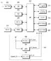
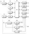
도 3은 본 발명의 제2 실시 예에 따른 모바일 단말의 블록도이다. 도 3의 모바일 단말은 본 발명의 제2 실시 예에 따른 전원 공급 장치(300)를 포함한다. 도 3에서 전원 공급 장치(300) 이외의 나머지 구성 요소들은 전술한 도 2와 동일하므로, 이들에 관한 설명은 생략한다.3 is a block diagram of a mobile terminal according to a second embodiment of the present invention. The mobile terminal of FIG. 3 includes a
도 3을 참조하면, 전원 공급 장치(300)는 벅 컨버터들(302, 304), LDO(306)를 포함한다. 벅 컨버터(302)는 배터리 전원 BT로부터 코어 전원 VT_Core를 생성하여 전면 카메라(222)에 공급한다. 벅 컨버터(304)는 배터리 전원 BT로부터 센서 전원 VT_Sensor를 생성하여 전면 카메라(222)에 공급한다. LDO(306)는 배터리 전원 BT로부터 입출력 전원 VT_IO를 생성하여 전면 카메라(222)에 공급한다.Referring to FIG. 3,
예를 들어 배터리 전원 BT, 코어 전원 VT_Core, 센서 전원 VT_Sensor, 입출력 전원 VT_IO 각각의 전압이 3.8V, 1.5V, 2.8V, 1.8V이고, 전면 카메라(222)의 부하단 소모 전류, 즉 코어 프로세서, 이미지 센서, 입출력부 각각의 소모 전류가 100mA, 30mA, 5mA이며, 벅 컨버터들(302, 304)의 효율이 90%라고 가정할 때, 입력단 소모 전류들, 즉 코어 전원 VT_Core, 센서 전원 VT_Sensor, 입출력 전원 VT_IO 각각의 입력단 소모 전류는 하기 표 3과 같이 된다.For example, when the voltages of the battery power BT, the core power VT_Core, the sensor power VT_Sensor, and the input / output power VT_IO are 3.8 V, 1.5 V, 2.8 V, and 1.8 V, respectively, Assuming that the consumed current of each of the image sensor and the input and output unit is 100 mA, 30 mA and 5 mA, and the efficiency of the
전원action
power
전원 전압[V]action
Power supply voltage [V]
소모 전류[mA]Subordinate
Current consumption [mA]
전압[v]battery
Voltage [v]
소모 전류[mA]Input
Current consumption [mA]
3.8
3.8
상기 표 3에서 보는 바와 같이 LDO(306)에 의해 생성되는 입출력 전원 VT_IO의 입력단 소모 전류는 부하단 소모 전류와 같지만, 코어 전원 VT_Core, 센서 전원 VT_Sensor 각각의 입력단 소모 전류는 43.85mA, 24.56mA로 부하단 소모 전류에 비해 작다. 코어 전원 VT_Core의 입력단 소모 전류의 계산식은 상기 표 1에 관한 설명과 같고, 센서 전원 VT_Sensor의 입력단 소모 전류의 계산식도 이와 마찬가지로 센서 전원 VT_Sensor 전압 * 부하단 소모 전류 / 배터리 전압 / 90%이다.As shown in Table 3, the input terminal consumption current of the input / output power supply VT_IO generated by the
상기 표 3을 상기 표 2와 비교해 보면, 전체 입력단 소모 전류가 135mA에서 73.41mA로 대폭적으로 감소됨을 알 수 있다.Comparing Table 3 with Table 2, it can be seen that the total input terminal current consumption is drastically reduced from 135 mA to 73.41 mA.
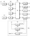
도 4는 본 발명의 제3 실시 예에 따른 모바일 단말의 블록도이다. 도 4의 모바일 단말은 본 발명의 제3 실시 예에 따른 전원 공급 장치(400)를 포함한다. 도 4에서 전원 공급 장치(400) 이외의 나머지 구성 요소들은 전술한 도 2와 동일하므로, 이들에 관한 설명은 생략한다.4 is a block diagram of a mobile terminal according to a third embodiment of the present invention. The mobile terminal of FIG. 4 includes a
도 4를 참조하면, 전원 공급 장치(400)는 벅 컨버터들(402, 406), LDO(404)를 포함한다. 벅 컨버터(402)는 배터리 전원 BT로부터 코어 전원 VT_Core를 생성하여 전면 카메라(222)에 공급한다. LDO(404)는 배터리 전원 BT로부터 센서 전원 VT_Sensor를 생성하여 전면 카메라(222)에 공급한다. 벅 컨버터(406)는 배터리 전원 BT로부터 입출력 전원 VT_IO를 생성하여 전면 카메라(222)에 공급한다.Referring to FIG. 4,
예를 들어 배터리 전원 BT, 코어 전원 VT_Core, 센서 전원 VT_Sensor, 입출력 전원 VT_IO 각각의 전압이 3.8V, 1.5V, 2.8V, 1.8V이고, 전면 카메라(222)의 부하단 소모 전류, 즉 코어 프로세서, 이미지 센서, 입출력부 각각의 소모 전류가 100mA, 30mA, 5mA이며, 벅 컨버터들(402, 406)의 효율이 90%라고 가정할 때, 입력단 소모 전류들, 즉 코어 전원 VT_Core, 센서 전원 VT_Sensor, 입출력 전원 VT_IO 각각의 입력단 소모 전류는 하기 표 4와 같이 된다.For example, when the voltages of the battery power BT, the core power VT_Core, the sensor power VT_Sensor, and the input / output power VT_IO are 3.8 V, 1.5 V, 2.8 V, and 1.8 V, respectively, Assuming that the consumption currents of the image sensor and the input and output units are 100 mA, 30 mA and 5 mA and the efficiency of the
전원action
power
전원 전압[V]action
Power supply voltage [V]
소모 전류[mA]Subordinate
Current consumption [mA]
전압[v]battery
Voltage [v]
소모 전류[mA]Input
Current consumption [mA]
3.8
3.8
상기 표 4에서 보는 바와 같이 LDO(404)에 의해 생성되는 센서 전원 VT_Sensor의 입력단 소모 전류는 부하단 소모 전류와 같지만, 코어 전원 VT_Core, 입출력 전원 VT_IO 각각의 입력단 소모 전류는 43.85mA, 2.63mA로 부하단 소모 전류에 비해 작다. 코어 전원 VT_Core의 입력단 소모 전류의 계산식은 상기 표 1에 관한 설명과 같고, 입출력 전원 VT_IO의 입력단 소모 전류의 계산식도 이와 마찬가지로 입출력 전원 VT_IO 전압 * 부하단 소모 전류 / 배터리 전압 / 90%이다.As shown in Table 4, the input terminal consumption current of the sensor power VT_Sensor generated by the
상기 표 4를 상기 표 2와 비교해 보면, 전체 입력단 소모 전류가 135mA에서 76.48mA로 대폭적으로 감소됨을 알 수 있다.Comparing Table 4 with Table 2, it can be seen that the total input current consumption is drastically reduced from 135 mA to 76.48 mA.
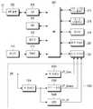
도 5는 발명의 제4 실시 예에 따른 모바일 단말의 블록도이다. 도 5의 모바일 단말은 본 발명의 제4 실시 예에 따른 전원 공급 장치(500)를 포함한다. 도 5에서 전원 공급 장치(500) 이외의 나머지 구성 요소들은 전술한 도 2와 동일하므로, 이들에 관한 설명은 생략한다.5 is a block diagram of a mobile terminal according to a fourth embodiment of the invention. The mobile terminal of FIG. 5 includes a
도 5를 참조하면, 전원 공급 장치(500)는 벅 컨버터들(502~506)을 포함한다. 벅 컨버터(502)는 배터리 전원 BT로부터 코어 전원 VT_Core를 생성하여 전면 카메라(222)에 공급한다. 벅 컨버터(504)는 배터리 전원 BT로부터 센서 전원 VT_Sensor를 생성하여 전면 카메라(222)에 공급한다. 벅 컨버터(506)는 배터리 전원 BT로부터 입출력 전원 VT_IO를 생성하여 전면 카메라(222)에 공급한다.Referring to FIG. 5,
예를 들어 배터리 전원 BT, 코어 전원 VT_Core, 센서 전원 VT_Sensor, 입출력 전원 VT_IO 각각의 전압이 3.8V, 1.5V, 2.8V, 1.8V이고, 전면 카메라(222)의 부하단 소모 전류, 즉 코어 프로세서, 이미지 센서, 입출력부 각각의 소모 전류가 100mA, 30mA, 5mA이며, 벅 컨버터들(502~506)의 효율이 90%라고 가정할 때, 입력단 소모 전류들, 즉 코어 전원 VT_Core, 센서 전원 VT_Sensor, 입출력 전원 VT_IO 각각의 입력단 소모 전류는 하기 표 5와 같이 된다.For example, when the voltages of the battery power BT, the core power VT_Core, the sensor power VT_Sensor, and the input / output power VT_IO are 3.8 V, 1.5 V, 2.8 V, and 1.8 V, respectively, Assuming that the consumed currents of the image sensor and the input and output units are 100 mA, 30 mA and 5 mA and the efficiency of the
전원action
power
전원 전압[V]action
Power supply voltage [V]
소모 전류[mA]Subordinate
Current consumption [mA]
전압[v]battery
Voltage [v]
소모 전류[mA]Input
Current consumption [mA]
3.8
3.8
상기 표 5에서 보는 바와 같이 코어 전원 VT_Core, 센서 전원 VT_Sensor, 입출력 전원 VT_IO 각각의 입력단 소모 전류는 43.85mA, 24.56mA, 2.63mA로 부하단 소모 전류에 비해 작다. 코어 전원 VT_Core의 입력단 소모 전류의 계산식은 상기 표 1에 관한 설명과 같고, 센서 전원 VT_Sensor의 입력단 소모 전류의 계산식은 상기 표 3에 관한 설명과 같으며, 입출력 전원 VT_IO의 입력단 소모 전류의 계산식은 상기 표 4에 관한 설명과 같다.As shown in Table 5, the input terminal consumption currents of the core power VT_Core, the sensor power VT_Sensor, and the input / output power VT_IO are 43.85 mA, 24.56 mA, and 2.63 mA, respectively, The formula for calculating the input terminal consumption current of the core power VT_Core is the same as the description related to Table 1, the calculation formula of the input terminal consumption current of the sensor power VT_Sensor is as described in Table 3, and the calculation formula of the input terminal consumption current of the input / Table 4 shows the description.
상기 표 5를 상기 표 2와 비교해 보면, 전체 입력단 소모 전류가 135mA에서 71.04mA로 대폭적으로 감소됨을 알 수 있다.Comparing Table 5 with Table 2, it can be seen that the total input terminal current consumption is drastically reduced from 135 mA to 71.04 mA.
도 6은 본 발명의 제5 실시 예에 따른 모바일 단말의 블록도이다. 도 6의 모바일 단말은 본 발명의 제5 실시 예에 따른 전원 공급 장치(600)를 포함한다. 도 6에서 전원 공급 장치(600) 이외의 나머지 구성 요소들은 전술한 도 2와 동일하므로, 이들에 관한 설명은 생략한다.6 is a block diagram of a mobile terminal according to a fifth embodiment of the present invention. The mobile terminal of FIG. 6 includes a
도 6을 참조하면, 전원 공급 장치(600)는 벅 컨버터(602), LDO(604), 로드 스위치(606)를 포함한다. 벅 컨버터(602)는 배터리 전원 BT로부터 코어 전원 VT_Core를 생성하여 전면 카메라(222)에 공급한다. LDO(604)는 배터리 전원 BT로부터 센서 전원 VT_Sensor를 생성하여 전면 카메라(222)에 공급한다. 로드 스위치(606)는 시스템 입출력 전원 System_IO를 입출력 전원 VT_IO으로 전면 카메라(222)에 공급한다. 시스템 입출력 전원 System_IO은 PMIC(212)에 의해 생성되는 전원들 중에 모바일 단말의 각종 입출력부들에 공통으로 사용되는 전원이다.6,
전면 카메라(222)와 같은 카메라 디바이스는 노이즈에 민감한 소자이므로, 통상적으로 전원 노이즈 감소를 위해 코어 전원 VT_Core, 센서 전원 VT_Sensor처럼 노이즈에 민감한 동작 전원들은 단독 전원이 사용된다. 하지만 입출력 전원 VT_IO처럼 노이즈에 상대적으로 덜 민감한 동작 전원은 전압이 같고 소비 전력이 높지 않다면 시스템 입출력 전원 System_IO과 같은 공통 전원을 사용할 수도 있다. 그러므로 전원 공급 장치(600)는 입출력 전원 VT_IO의 전압이 시스템 입출력 전원 System_IO의 전압과 같은 경우에, 입출력 전원 VT_IO을 별도의 전원 공급 장치에 의해 생성하는 대신에 로드 스위치(606)에 의해 시스템 입출력 전원 System_IO을 입출력 전원 VT_IO으로 공급하는 경우의 실시 예이다. 통상적으로 로드 스위치는 전원 공급을 단속하는 소자로서, 전원 공급을 외부의 제어에 의해 단속할 필요가 있는 경우에 사용된다.Since the camera device such as the
예를 들어 배터리 전원 BT, 코어 전원 VT_Core, 센서 전원 VT_Sensor, 입출력 전원 VT_IO 각각의 전압이 3.8V, 1.5V, 2.8V, 1.8V이고, 전면 카메라(222)의 부하단 소모 전류, 즉 코어 프로세서, 이미지 센서, 입출력부 각각의 소모 전류가 100mA, 30mA, 5mA이며, 벅 컨버터(602)의 효율이 90%라고 가정할 때, 입력단 소모 전류들, 즉 코어 전원 VT_Core, 센서 전원 VT_Sensor, 입출력 전원 VT_IO 각각의 입력단 소모 전류는 하기 표 6과 같이 된다. 또한 하기 표 6는 입출력 전원 VT_IO으로 공급되는 시스템 입출력 전원 System_IO가 PMIC(212)에서 효율이 90%인 스위칭 레귤레이터에 의해 생성되는 경우의 예이다.For example, when the voltages of the battery power BT, the core power VT_Core, the sensor power VT_Sensor, and the input / output power VT_IO are 3.8 V, 1.5 V, 2.8 V, and 1.8 V, respectively, Assuming that the consumption currents of the image sensor and the input and output units are 100 mA, 30 mA and 5 mA, respectively, and the efficiency of the
전원action
power
전원 전압[V]action
Power supply voltage [V]
소모 전류[mA]Subordinate
Current consumption [mA]
전압[v]battery
Voltage [v]
소모 전류[mA]Input
Current consumption [mA]
3.8
3.8
상기 표 6에서 보는 바와 같이 LDO(604)에 의해 생성되는 센서 전원 VT_Sensor의 입력단 소모 전류는 부하단 소모 전류와 같지만, 코어 전원 VT_Core, 입출력 전원 VT_IO 각각의 입력단 소모 전류는 43.85mA, 2.63mA로 부하단 소모 전류에 비해 작다. 코어 전원 VT_Core의 입력단 소모 전류의 계산식은 상기 표 1에 관한 설명과 같고, 입출력 전원 VT_IO의 입력단 소모 전류의 계산식은 상기 표 4에 관한 설명과 같다.As shown in Table 6, the input terminal consumption current of the sensor power VT_Sensor generated by the
상기 표 6을 상기 표 2와 비교해 보면, 전체 입력단 소모 전류가 135mA에서 76.48mA로 대폭적으로 감소됨을 알 수 있다.Comparing Table 6 with Table 2, it can be seen that the total input current consumption is drastically reduced from 135 mA to 76.48 mA.
도 7은 본 발명의 제6 실시 예에 따른 모바일 단말의 블록도이다. 도 7의 모바일 단말은 본 발명의 제6 실시 예에 따른 전원 공급 장치(700)를 포함한다. 도 7에서 전원 공급 장치(700) 이외의 나머지 구성 요소들은 전술한 도 2와 동일하므로, 이들에 관한 설명은 생략한다.7 is a block diagram of a mobile terminal according to a sixth embodiment of the present invention. The mobile terminal of FIG. 7 includes a
도 7을 참조하면, 전원 공급 장치(700)는 벅 컨버터들(702, 704), 로드 스위치(706)를 포함한다. 벅 컨버터(702)는 배터리 전원 BT로부터 코어 전원 VT_Core를 생성하여 전면 카메라(222)에 공급한다. 벅 컨버터(704)는 배터리 전원 BT로부터 센서 전원 VT_Sensor를 생성하여 전면 카메라(222)에 공급한다. 로드 스위치(706)는 시스템 입출력 전원 System_IO를 입출력 전원 VT_IO으로 전면 카메라(222)에 공급한다.Referring to FIG. 7,
예를 들어 배터리 전원 BT, 코어 전원 VT_Core, 센서 전원 VT_Sensor, 입출력 전원 VT_IO 각각의 전압이 3.8V, 1.5V, 2.8V, 1.8V이고, 전면 카메라(222)의 부하단 소모 전류, 즉 코어 프로세서, 이미지 센서, 입출력부 각각의 소모 전류가 100mA, 30mA, 5mA이며, 벅 컨버터들(702, 704)의 효율이 90%라고 가정할 때, 입력단 소모 전류들, 즉 코어 전원 VT_Core, 센서 전원 VT_Sensor, 입출력 전원 VT_IO 각각의 입력단 소모 전류는 상기 표 5와 동일하게 하기 표 7과 같이 된다. 또한 하기 표 7은 입출력 전원 VT_IO으로 공급되는 시스템 입출력 전원 System_IO가 PMIC(212)에서 효율이 90%인 스위칭 레귤레이터에 의해 생성되는 경우의 예이다.For example, when the voltages of the battery power BT, the core power VT_Core, the sensor power VT_Sensor, and the input / output power VT_IO are 3.8 V, 1.5 V, 2.8 V, and 1.8 V, respectively, Assuming that the consumed current of each of the image sensor and the input and output unit is 100 mA, 30 mA and 5 mA, and the efficiency of the
전원action
power
전원 전압[V]action
Power supply voltage [V]
소모 전류[mA]Subordinate
Current consumption [mA]
전압[v]battery
Voltage [v]
소모 전류[mA]Input
Current consumption [mA]
3.8
3.8
도 8은 본 발명의 제7 실시 예에 따른 모바일 단말의 블록도이다. 도 8에서 전원 공급 장치(800) 이외의 나머지 구성 요소들은 전술한 도 2와 동일하므로, 이들에 관한 설명은 생략한다.8 is a block diagram of a mobile terminal according to a seventh embodiment of the present invention. 8, components other than the
도 8을 참조하면, 전원 공급 장치(800)는 벅 컨버터(802), LDO들(804, 808), 로드 스위치(806)를 포함한다. 벅 컨버터(802)는 배터리 전원 BT로부터 서브 전원을 생성한다. LDO(804)는 벅 컨버터(802)에 의해 생성된 서브 전원으로부터 코어 전원 VT_Core를 생성하여 전면 카메라(222)에 공급한다. 로드 스위치(806)는 벅 컨버터(802)에 의해 생성된 서브 전원을 센서 전원 VT_Sensor으로 전면 카메라(222)에 공급한다. LDO(808)는 벅 컨버터(802)에 의해 생성된 서브 전원을 입출력 전원 VT_IO으로 전면 카메라(222)에 공급한다.8, the
상기 전원 공급 장치(800)는 센서 전원 VT_Sensor의 전압이 코어 전원 VT_Core, 입출력 전원 VT_IO 각각의 전압보다 높은 경우의 실시 예에 따라 구성된 것이다. 그러므로 벅 컨버터(802)는 센서 전원 VT_Sensor의 전압과 동일하면서 코어 전원 VT_Core, 입출력 전원 VT_IO 각각의 전압보다는 높은 전압의 서브 전원을 배터리 전원 BT로부터 생성한다.The
예를 들어 배터리 전원 BT, 코어 전원 VT_Core, 센서 전원 VT_Sensor, 입출력 전원 VT_IO 각각의 전압이 3.8V, 1.5V, 2.8V, 1.8V인 경우, 벅 컨버터(802)는 2.8V의 서브 전원을 생성한다.For example, when the voltages of the battery power BT, the core power VT_Core, the sensor power VT_Sensor, and the input / output power VT_IO are 3.8V, 1.5V, 2.8V, and 1.8V, the
이러한 경우 전면 카메라(222)의 부하단 소모 전류, 즉 코어 프로세서, 이미지 센서, 입출력부 각각의 소모 전류가 100mA, 30mA, 5mA이며, 벅 컨버터(802)의 효율이 90%라고 가정할 때, 입력단 소모 전류들, 즉 코어 전원 VT_Core, 센서 전원 VT_Sensor, 입출력 전원 VT_IO 각각의 입력단 소모 전류는 하기 표 8과 같이 된다.In this case, assuming that the consumed current of each of the bottom-end consumed current of the front-
전원action
power
전원 전압[V]serve
Power supply voltage [V]
전원 전압[V]action
Power supply voltage [V]
소모 전류[mA]Subordinate
Current consumption [mA]
전압[v]battery
Voltage [v]
소모 전류[mA]Input
Current consumption [mA]
2.8
2.8
3.8
3.8
상기 표 8에서 보는 바와 같이 코어 전원 VT_Core, 센서 전원 VT_Sensor, 입출력 전원 VT_IO 각각의 입력단 소모 전류는 81.87mA, 24.56mA, 4.09mA로 부하단 소모 전류에 비해 작다. 코어 전원 VT_Core, 센서 전원 VT_Sensor, 입출력 전원 VT_IO 각각의 입력단 소모 전류의 계산식은 서브 전원 전압 * 부하단 소모 전류 / 배터리 전압 / 90%이 된다.As shown in Table 8, the input terminal consumption currents of the core power VT_Core, the sensor power VT_Sensor, and the input / output power VT_IO are 81.87 mA, 24.56 mA, and 4.09 mA, respectively, The calculation formula of the core power VT_Core, the sensor power VT_Sensor, and the input / output power VT_IO is as follows: sub power supply voltage * lower consumption current / battery voltage / 90%.
상기 표 8을 상기 표 2와 비교해 보면, 전체 입력단 소모 전류가 135mA에서 110.52mA로 감소됨을 알 수 있다.Comparing Table 8 with Table 2, it can be seen that the total input current consumption is reduced from 135 mA to 110.52 mA.
도 9는 본 발명의 제8 실시 예에 따른 모바일 단말의 블록도이다. 도 9에서 전원 공급 장치(900) 이외의 나머지 구성 요소들은 전술한 도 2와 동일하므로, 이들에 관한 설명은 생략한다.9 is a block diagram of a mobile terminal according to an eighth embodiment of the present invention. The remaining components in FIG. 9 other than the
도 9를 참조하면, 전원 공급 장치(900)는 벅 컨버터(902), 로드 스위치들(904~908)를 포함한다. 벅 컨버터(902)는 배터리 전원 BT로부터 서브 전원을 생성한다. 로드 스위치(904)는 벅 컨버터(902)에 의해 생성된 서브 전원을 코어 전원 VT_Core으로 전면 카메라(222)에 공급한다. 로드 스위치(906)는 벅 컨버터(902)에 의해 생성된 서브 전원을 센서 전원 VT_Sensor으로 전면 카메라(222)에 공급한다. 로드 스위치(908)는 벅 컨버터(902)에 의해 생성된 서브 전원을 입출력 전원 VT_IO으로 전면 카메라(222)에 공급한다.9,
상기 전원 공급 장치(900)는 코어 전원 VT_Core, 센서 전원 VT_Sensor, 입출력 전원 VT_IO 각각의 전압이 동일한 경우의 실시 예에 따라 구성된 것이다. 그러므로 벅 컨버터(902)는 센서 전원 VT_Sensor, 코어 전원 VT_Core, 입출력 전원 VT_IO 각각의 전압과 동일한 전압의 서브 전원을 배터리 전원 BT로부터 생성한다.The
예를 들어 배터리 전원 BT의 전압이 3.8V이고, 코어 전원 VT_Core, 센서 전원 VT_Sensor, 입출력 전원 VT_IO 각각의 전압은 1.8V인 경우, 벅 컨버터(902)는 1.8V의 서브 전원을 생성한다.For example, when the voltage of the battery power BT is 3.8 V, and the voltages of the core power VT_Core, the sensor power VT_Sensor, and the input / output power VT_IO are 1.8 V, the
이러한 경우 전면 카메라(222)의 부하단 소모 전류, 즉 코어 프로세서, 이미지 센서, 입출력부 각각의 소모 전류가 100mA, 30mA, 5mA이며, 벅 컨버터(902)의 효율이 90%라고 가정할 때, 입력단 소모 전류들, 즉 코어 전원 VT_Core, 센서 전원 VT_Sensor, 입출력 전원 VT_IO 각각의 입력단 소모 전류는 하기 표 9와 같이 된다.In this case, assuming that the consumed current of each of the bottom-end consumed current of the front-
전원action
power
전원 전압[V]serve
Power supply voltage [V]
전원 전압[V]action
Power supply voltage [V]
소모 전류[mA]Subordinate
Current consumption [mA]
전압[v]battery
Voltage [v]
소모 전류[mA]Input
Current consumption [mA]
1.8
1.8
3.8
3.8
상기 표 9에서 보는 바와 같이 코어 전원 VT_Core, 센서 전원 VT_Sensor, 입출력 전원 VT_IO 각각의 입력단 소모 전류는 52.63mA, 15.78mA, 2.63mA로 부하단 소모 전류에 비해 작다. 코어 전원 VT_Core, 센서 전원 VT_Sensor, 입출력 전원 VT_IO 각각의 입력단 소모 전류의 계산식은 서브 전원 전압 * 부하단 소모 전류 / 배터리 전압 / 90%이 된다.As shown in Table 9, the input terminal consumption currents of the core power VT_Core, the sensor power VT_Sensor, and the input / output power VT_IO are 52.63 mA, 15.78 mA, and 2.63 mA, respectively, The calculation formula of the core power VT_Core, the sensor power VT_Sensor, and the input / output power VT_IO is as follows: sub power supply voltage * lower consumption current / battery voltage / 90%.
상기 표 9를 상기 표 2와 비교해 보면, 전체 입력단 소모 전류가 135mA에서 71.04mA로 대폭적으로 감소됨을 알 수 있다.Comparing Table 9 with Table 2, it can be seen that the total input current consumption is greatly reduced from 135 mA to 71.04 mA.
도 10은 본 발명의 제9 실시 예에 따른 모바일 단말의 블록도이다. 도 10에서 전원 공급 장치(1000) 이외의 나머지 구성 요소들은 전술한 도 2와 동일하므로, 이들에 관한 설명은 생략한다.10 is a block diagram of a mobile terminal according to a ninth embodiment of the present invention. The remaining components in FIG. 10 other than the
도 10을 참조하면, 전원 공급 장치(1000)는 벅 컨버터(1002), LDO들(1004, 1006), 로드 스위치(1008)를 포함한다. 벅 컨버터(1002)는 배터리 전원 BT로부터 서브 전원을 생성한다. LDO(1004)는 벅 컨버터(1002)에 의해 생성된 서브 전원으로부터 코어 전원 VT_Core을 생성하여 전면 카메라(222)에 공급한다. LDO(1006)는 벅 컨버터(1002)에 의해 생성된 서브 전원으로부터 센서 전원 VT_Sensor을 생성하여 전면 카메라(222)에 공급한다. 로드 스위치(1008)는 벅 컨버터(1002)에 의해 생성된 서브 전원을 입출력 전원 VT_IO으로 전면 카메라(222)에 공급한다.10, the
상기 전원 공급 장치(1000)는 센서 전원 VT_Sensor의 전압이 코어 전원 VT_Core, 입출력 전원 VT_IO 각각의 전압보다 높고, 입출력 전원 VT_IO의 전압이 코어 전원 VT_Core의 전압보다 높은 경우에, 입출력 전원 VT_IO의 전압과 동일한 서브 전원을 벅 컨버터(1002)에 의해 생성하는 실시 예에 따라 구성된 것이다. 그러므로 벅 컨버터(1002)는 코어 전원 VT_Core의 전압보다는 높으면서 입출력 전원 VT_IO과 같은 전압의 서브 전원을 배터리 전원 BT로부터 생성한다.When the voltage of the sensor power VT_Sensor is higher than the voltages of the core power supply VT_Core and the input / output power supply VT_IO and the voltage of the input / output power supply VT_IO is higher than the voltage of the core power supply VT_Core, And is configured according to an embodiment in which the sub power source is generated by the
예를 들어 배터리 전원 BT, 코어 전원 VT_Core, 센서 전원 VT_Sensor, 입출력 전원 VT_IO 각각의 전압이 3.8V, 1.5V, 2.8V, 1.8V인 경우, 벅 컨버터(1002)는 1.8V의 서브 전원을 생성한다.For example, when the voltages of the battery power BT, the core power VT_Core, the sensor power VT_Sensor, and the input / output power VT_IO are 3.8V, 1.5V, 2.8V, and 1.8V, the
이러한 경우 전면 카메라(222)의 부하단 소모 전류, 즉 코어 프로세서, 이미지 센서, 입출력부 각각의 소모 전류가 100mA, 30mA, 5mA이며, 벅 컨버터(1002)의 효율이 90%라고 가정할 때, 입력단 소모 전류들, 즉 코어 전원 VT_Core, 센서 전원 VT_Sensor, 입출력 전원 VT_IO 각각의 입력단 소모 전류는 하기 표 10과 같이 된다.In this case, assuming that the consumed currents of the bottom-end consumed current of the front-
전원action
power
전원 전압[V]serve
Power supply voltage [V]
전원 전압[V]action
Power supply voltage [V]
소모 전류[mA]Subordinate
Current consumption [mA]
전압[v]battery
Voltage [v]
소모 전류[mA]Input
Current consumption [mA]
3.8
3.8
상기 표 10에서 보는 바와 같이 LDO(1006)에 의해 생성되는 센서 전원 VT_Sensor의 입력단 소모 전류는 부하단 소모 전류와 같지만, 코어 전원 VT_Core, 입출력 전원 VT_IO 각각의 입력단 소모 전류는 52.63mA, 2.63mA로 부하단 소모 전류에 비해 작다. 코어 전원 VT_Core, 입출력 전원 VT_IO 각각의 입력단 소모 전류의 계산식은 상기 표 9에 관한 설명과 같다.As shown in Table 10, the input terminal consumption current of the sensor power VT_Sensor generated by the
도 11은 본 발명의 제10 실시 예에 따른 모바일 단말의 블록도이다. 도 11에서 전원 공급 장치(1100) 이외의 나머지 구성 요소들은 전술한 도 2와 동일하므로, 이들에 관한 설명은 생략한다.11 is a block diagram of a mobile terminal according to a tenth embodiment of the present invention. 11, components other than the
도 11을 참조하면, 전원 공급 장치(1100)는 벅 컨버터(1102), 로드 스위치들(1104, 1108), LDO(1106)를 포함한다. 벅 컨버터(1102)는 배터리 전원 BT로부터 서브 전원을 생성한다. 로드 스위치(1104)는 벅 컨버터(1102)에 의해 생성된 서브 전원을 코어 전원 VT_Core으로 전면 카메라(222)에 공급한다. LDO(1106)는 배터리 전원 BT로부터 센서 전원 VT_Sensor을 생성하여 전면 카메라(222)에 공급한다. 로드 스위치(1108)는 벅 컨버터(1102)에 의해 생성된 서브 전원을 입출력 전원 VT_IO으로 전면 카메라(222)에 공급한다.11,
상기 전원 공급 장치(1100)는 센서 전원 VT_Sensor의 전압이 코어 전원 VT_Core, 입출력 전원 VT_IO 각각의 전압보다 높고, 코어 전원 VT_Core과 입출력 전원 VT_IO의 전압이 동일한 경우에, 코어 전원 VT_Core, 입출력 전원 VT_IO 각각의 전압과 동일한 서브 전원을 벅 컨버터(1102)에 의해 생성하는 실시 예에 따라 구성된 것이다. 그러므로 벅 컨버터(1102)는 코어 전원 VT_Core, 입출력 전원 VT_IO 각각의 전압과 같은 전압의 서브 전원을 배터리 전원 BT로부터 생성한다.When the voltage of the sensor power VT_Sensor is higher than the voltage of each of the core power VT_Core and the input / output power VT_IO and the voltages of the core power VT_Core and the input / output power VT_IO are the same, the
예를 들어 배터리 전원 BT, 코어 전원 VT_Core, 센서 전원 VT_Sensor, 입출력 전원 VT_IO 각각의 전압이 3.8V, 1.8V, 2.8V, 1.8V인 경우, 벅 컨버터(1102)는 1.8V의 서브 전원을 생성한다.For example, when the voltages of the battery power BT, the core power VT_Core, the sensor power VT_Sensor, and the input / output power VT_IO are 3.8V, 1.8V, 2.8V, and 1.8V, the
이러한 경우 전면 카메라(222)의 부하단 소모 전류, 즉 코어 프로세서, 이미지 센서, 입출력부 각각의 소모 전류가 100mA, 30mA, 5mA이며, 벅 컨버터(1102)의 효율이 90%라고 가정할 때, 입력단 소모 전류들, 즉 코어 전원 VT_Core, 센서 전원 VT_Sensor, 입출력 전원 VT_IO 각각의 입력단 소모 전류는 상기 표 10과 동일하게 하기 표 11과 같이 된다.In this case, assuming that the consumed current of each of the bottom-end consumed current of the front-
전원action
power
전원 전압[V]serve
Power supply voltage [V]
전원 전압[V]action
Power supply voltage [V]
소모 전류[mA]Subordinate
Current consumption [mA]
전압[v]battery
Voltage [v]
소모 전류[mA]Input
Current consumption [mA]
3.8
3.8
상기 표 11에서 보는 바와 같이 LDO(1106)에 의해 생성되는 센서 전원 VT_Sensor의 입력단 소모 전류는 부하단 소모 전류와 같지만, 코어 전원 VT_Core, 입출력 전원 VT_IO 각각의 입력단 소모 전류는 52.63mA, 2.63mA로 부하단 소모 전류에 비해 작다. 코어 전원 VT_Core, 입출력 전원 VT_IO 각각의 입력단 소모 전류의 계산식은 상기 표 9에 관한 설명과 같다.As shown in Table 11, the input terminal consumption current of the sensor power VT_Sensor generated by the
상기 표 11을 상기 표 2와 비교해 보면, 전체 입력단 소모 전류가 135mA에서 85.26mA로 대폭적으로 감소됨을 알 수 있다.Comparing Table 11 with Table 2, it can be seen that the total input terminal current consumption is drastically reduced from 135 mA to 85.26 mA.
도 12는 본 발명의 제11 실시 예에 따른 모바일 단말의 블록도이다. 도 12에서 전원 공급 장치(1200) 이외의 나머지 구성 요소들은 전술한 도 2와 동일하므로, 이들에 관한 설명은 생략한다.12 is a block diagram of a mobile terminal according to an eleventh embodiment of the present invention. 12, components other than the
도 12를 참조하면, 전원 공급 장치(1200)는 벅 컨버터들(1202, 1204), 로드 스위치들(1206, 1208)을 포함한다. 벅 컨버터(1202)는 배터리 전원 BT로부터 코어 전원 VT_Core을 생성하여 전면 카메라(222)에 공급한다. 벅 컨버터(1204)는 배터리 전원 BT로부터 서브 전원을 생성한다. 로드 스위치(1206)는 벅 컨버터(1204)에 의해 생성된 서브 전원을 센서 전원 VT_Sensor으로 전면 카메라(222)에 공급한다. 로드 스위치(1208)는 벅 컨버터(1204)에 의해 생성된 서브 전원을 입출력 전원 VT_IO으로 전면 카메라(222)에 공급한다.12, the
상기 전원 공급 장치(1200)는 센서 전원 VT_Sensor과 입출력 전원 VT_IO의 전압이 동일한 경우에, 센서 전원 VT_Sensor, 입출력 전원 VT_IO 각각의 전압과 동일한 서브 전원을 벅 컨버터(1204)에 의해 생성하는 실시 예에 따라 구성된 것이다. 그러므로 벅 컨버터(1204)는 센서 전원 VT_Sensor, 입출력 전원 VT_IO 각각의 전압과 같은 전압의 서브 전원을 배터리 전원 BT로부터 생성한다.According to an embodiment in which the
예를 들어 배터리 전원 BT, 코어 전원 VT_Core, 센서 전원 VT_Sensor, 입출력 전원 VT_IO 각각의 전압이 3.8V, 1.5V, 1.8V, 1.8V인 경우, 벅 컨버터(1204)는 1.8V의 서브 전원을 생성한다.For example, when the voltages of the battery power BT, the core power VT_Core, the sensor power VT_Sensor, and the input / output power VT_IO are 3.8V, 1.5V, 1.8V, and 1.8V, the
이러한 경우 전면 카메라(222)의 부하단 소모 전류, 즉 코어 프로세서, 이미지 센서, 입출력부 각각의 소모 전류가 100mA, 30mA, 5mA이며, 벅 컨버터들(1202, 1204)의 효율이 90%라고 가정할 때, 입력단 소모 전류들, 즉 코어 전원 VT_Core, 센서 전원 VT_Sensor, 입출력 전원 VT_IO 각각의 입력단 소모 전류는 하기 표 12와 같이 된다.In this case, it is assumed that the consumed currents of the bottom-end consumed current of the front-
전원action
power
전원 전압[V]serve
Power supply voltage [V]
전원 전압[V]action
Power supply voltage [V]
소모 전류[mA]Subordinate
Current consumption [mA]
전압[v]battery
Voltage [v]
소모 전류[mA]Input
Current consumption [mA]
3.8
3.8
상기 표 12에서 보는 바와 같이, 코어 전원 VT_Core, 센서 전원 VT_Sensor, 입출력 전원 VT_IO 각각의 입력단 소모 전류는 43.85mA, 15.78mA, 2.63mA로 부하단 소모 전류에 비해 작다. 코어 전원 VT_Core, 센서 전원 VT_Sensor, 입출력 전원 VT_IO 각각의 입력단 소모 전류의 계산식은 당업자라면 전술한 설명들을 참조하면 용이하게 이해할 수 있을 것이다.As shown in Table 12, the input terminal consumption currents of the core power VT_Core, the sensor power VT_Sensor, and the input / output power VT_IO are 43.85 mA, 15.78 mA, and 2.63 mA, respectively. The calculation formulas of the input power consumption of the core power supply VT_Core, the sensor power supply VT_Sensor, and the input / output power supply VT_IO will be easily understood by those skilled in the art with reference to the above description.
상기 표 12를 상기 표 2와 비교해 보면, 전체 입력단 소모 전류가 135mA에서 62.26mA로 대폭적으로 감소됨을 알 수 있다.Comparing Table 12 with Table 2, it can be seen that the total input current consumption is drastically reduced from 135 mA to 62.26 mA.
도 13은 본 발명의 제12 실시 예에 따른 모바일 단말의 블록도이다. 도 13에서 전원 공급 장치(1300) 이외의 나머지 구성 요소들은 전술한 도 2와 동일하므로, 이들에 관한 설명은 생략한다.13 is a block diagram of a mobile terminal according to a twelfth embodiment of the present invention. The remaining components in FIG. 13 other than the
도 13을 참조하면, 전원 공급 장치(1300)는 벅 컨버터들(1302, 1304), 로드 스위치(1306), LDO(1308)를 포함한다. 벅 컨버터(1302)는 배터리 전원 BT로부터 코어 전원 VT_Core을 생성하여 전면 카메라(222)에 공급한다. 벅 컨버터(1304)는 배터리 전원 BT로부터 서브 전원을 생성한다. 로드 스위치(1306)는 벅 컨버터(1304)에 의해 생성된 서브 전원을 센서 전원 VT_Sensor으로 전면 카메라(222)에 공급한다. LDO(1308)는 벅 컨버터(1304)에 의해 생성된 서브 전원으로부터 입출력 전원 VT_IO을 생성하여 전면 카메라(222)에 공급한다.13, the
상기 전원 공급 장치(1300)는 센서 전원 VT_Sensor의 전압이 입출력 전원 VT_IO의 전압보다 높으며, 센서 전원 VT_Sensor과 동일한 전압의 서브 전원을 벅 컨버터(1304)에 의해 생성하는 경우의 실시 예에 따라 구성된 것이다. 그러므로 벅 컨버터(1304)는 센서 전원 VT_Sensor의 전압과 같은 전압의 서브 전원을 배터리 전원 BT로부터 생성한다.The
예를 들어 배터리 전원 BT, 코어 전원 VT_Core, 센서 전원 VT_Sensor, 입출력 전원 VT_IO 각각의 전압이 3.8V, 1.5V, 2.8V, 1.8V인 경우, 벅 컨버터(1304)는 2.8V의 서브 전원을 생성한다.For example, when the voltages of the battery power BT, the core power VT_Core, the sensor power VT_Sensor, and the input / output power VT_IO are 3.8V, 1.5V, 2.8V, and 1.8V, the
이러한 경우 전면 카메라(222)의 부하단 소모 전류, 즉 코어 프로세서, 이미지 센서, 입출력부 각각의 소모 전류가 100mA, 30mA, 5mA이며, 벅 컨버터들(1302, 1304)의 효율이 90%라고 가정할 때, 입력단 소모 전류들, 즉 코어 전원 VT_Core, 센서 전원 VT_Sensor, 입출력 전원 VT_IO 각각의 입력단 소모 전류는 하기 표 13과 같이 된다.In this case, it is assumed that the consumed currents of the bottom-end consumed current of the
전원action
power
전원 전압[V]serve
Power supply voltage [V]
전원 전압[V]action
Power supply voltage [V]
소모 전류[mA]Subordinate
Current consumption [mA]
전압[v]battery
Voltage [v]
소모 전류[mA]Input
Current consumption [mA]
3.8
3.8
상기 표 13에서 보는 바와 같이, 코어 전원 VT_Core, 센서 전원 VT_Sensor, 입출력 전원 VT_IO 각각의 입력단 소모 전류는 43.85mA, 24.56mA, 2.63mA로 부하단 소모 전류에 비해 작다. 코어 전원 VT_Core, 센서 전원 VT_Sensor, 입출력 전원 VT_IO 각각의 입력단 소모 전류의 계산식은 당업자라면 전술한 설명들을 참조하면 용이하게 이해할 수 있을 것이다.As shown in Table 13, the input terminal consumption currents of the core power VT_Core, the sensor power VT_Sensor, and the input / output power VT_IO are 43.85 mA, 24.56 mA, and 2.63 mA, respectively, The calculation formulas of the input power consumption of the core power supply VT_Core, the sensor power supply VT_Sensor, and the input / output power supply VT_IO will be easily understood by those skilled in the art with reference to the above description.
상기 표 13을 상기 표 2와 비교해 보면, 전체 입력단 소모 전류가 135mA에서 72.50mA로 대폭적으로 감소됨을 알 수 있다.Comparing Table 13 with Table 2, it can be seen that the total input terminal current consumption is drastically reduced from 135 mA to 72.50 mA.
코어 전원 VT_Core, 센서 전원 VT_Sensor, 입출력 전원 VT_IO 각각의 전압, 소비 전력, 모바일 단말 내의 공간 크기 등을 감안하여 상술한 본 발명의 실시 예들 중에 어느 하나의 실시 예 또는 해당 실시 예에 대응하는 구성에 따라 카메라 디바이스 전원 공급 장치를 다양하게 구성할 수 있다. 이에 따라 모바일 단말들 각각에 있어서 코어 전원 VT_Core, 센서 전원 VT_Sensor, 입출력 전원 VT_IO 각각의 전압, 소비 전력, 모바일 단말 내의 공간 크기 등에 따라 각각의 모바일 단말에 최적화된 카메라 디바이스 전원 공급 장치가 제공될 수 있다.The voltage of each of the core power source VT_Core, the sensor power source VT_Sensor, and the input / output power source VT_IO, power consumption, space size in the mobile terminal, and the like, or according to the configuration corresponding to the embodiment of the present invention The camera device power supply can be configured in various ways. Accordingly, in each of the mobile terminals, a camera device power supply device optimized for each mobile terminal can be provided according to the voltage of each of the core power VT_Core, the sensor power VT_Sensor, the input / output power VT_IO, power consumption, .
한편 전면 카메라(222)와 같은 카메라 디바이스는 카메라 디바이스마다 고유의 파워 시퀀스를 가질 수 있다. 파워 시퀀스는 코어 전원 VT_Core, 센서 전원 VT_Sensor, 입출력 전원 VT_IO 각각에 관한 특정한 공급 타이밍을 규정한다.Meanwhile, a camera device such as the
도 14는 전면 카메라 파워 시퀀스 예시도로서, 통상적인 파워 시퀀스의 일예를 보인 것이다. 도 14에 따른 파워 시퀀스 제어는 AP(200)에 의해 이루어질 수 있다. 이러한 경우 AP(200)는 파워 시퀀스에 따라 벅 컨버터의 인에이블 단자, LDO의 인에이블 단자, 로드 스위치의 스위칭 제어 단자를 통해 벅 컨버터, LDO, 로드 스위치를 제어함으로써, 전면 카메라(222)에 대한 코어 전원 VT_Core, 센서 전원 VT_Sensor, 입출력 전원 VT_IO 각각의 공급을 선택적으로 단속한다.Fig. 14 is an illustration of a front camera power sequence, showing an example of a typical power sequence. Fig. The power sequence control according to Fig. 14 can be performed by the
도 14를 참조하면, 코어 전원 VT_Core가 먼저 t1 시점에 공급된 이후에, 예를 들어 센서 전원 VT_Sensor, 입출력 전원 VT_IO는 코어 전원 VT_Core의 공급 시점인 t1 시점으로부터 1ms 내에 공급되어야 한다.Referring to FIG. 14, after the core power source VT_Core is first supplied at time t1, for example, the sensor power VT_Sensor and the input / output power VT_IO must be supplied within 1 ms from the time t1, which is the supply timing of the core power VT_Core.
또한 코어 전원 VT_Core, 센서 전원 VT_Sensor, 입출력 전원 VT_IO이 모두 공급되기 시작한 t2 시점으로부터 적어도 20㎲ 경과 후에 전면 카메라 인에이블 신호 VT_Enable가 액티브되어야 한다. 전면 카메라 인에이블 신호 VT_Enable는 전면 카메라를 인에이블시키기 위한 신호이다. 또한 코어 전원 VT_Core, 센서 전원 VT_Sensor, 입출력 전원 VT_IO이 모두 공급되기 시작한 t2 시점으로부터 적어도 0㎲ 경과 후에 메인 클럭신호 MCLK가 공급되어야 한다. 메인 클럭신호 MCLK는 전면 카메라의 동작을 위한 클럭 신호이다. 그리고 t2 시점으로부터 적어도 4ms 경과 후에 전면 카메라 리셋신호 VT_Reset가 액티브되어야 한다. 또한 카메라 인에이블 신호 VT_Enable는 전면 카메라 리셋신호 VT_Reset가 액티브된 t3 시점으로부터 적어도 4ms 경과 후에 넌-액티브되어야 한다.Also, the front camera enable signal VT_Enable must be active after at least 20 μs elapse from the time point t2 when both the core power VT_Core, the sensor power VT_Sensor, and the input / output power VT_IO are supplied. The front camera enable signal VT_Enable is a signal for enabling the front camera. Also, the main clock signal MCLK must be supplied at least 0 μs after the time point t2 when the core power supply VT_Core, the sensor power supply VT_Sensor, and the input / output power supply VT_IO all start to be supplied. The main clock signal MCLK is a clock signal for the operation of the front side camera. Then, the front camera reset signal VT_Reset must be activated at least 4 ms after the time point t2. Also, the camera enable signal VT_Enable must be non-active after at least 4 ms from the time t3 when the front camera reset signal VT_Reset is active.
전면 카메라는 전면 카메라 리셋신호 VT_Reset의 액티브에 따라 초기화를 완료한 후 이미지 센서에 의해 촬영된 이미지 데이터를 AP로 전송하기 시작한다.The front camera starts to transmit the image data photographed by the image sensor to the AP after completing the initialization according to the active of the front camera reset signal VT_Reset.
한편 상술한 본 발명의 설명에서는 구체적인 실시 예들에 관해 설명하였으나, 본 발명의 범위를 벗어나지 않는 한도 내에서 여러 가지 변형이 가능하다. 예를 들어 전면 카메라(222)로서 도 14의 예와 같은 파워 시퀀스에 따른 코어 전원 VT_Core, 센서 전원 VT_Sensor, 입출력 전원 VT_IO의 공급 시점을 제어하지 않아도 문제가 없는 제품을 사용할 경우, 코어 전원 VT_Core, 센서 전원 VT_Sensor, 입출력 전원 VT_IO의 공급 타이밍을 별도로 제어할 필요가 없다. 이러한 경우 도 6 내지 도 13의 로드 스위치들(606, 706, 806, 904, 906, 1008, 1104, 1108, 1206, 1208, 1306)은 사용할 필요가 없다. 즉, 로드 스위치들(606, 706, 806, 904, 906, 1008, 1104, 1108, 1206, 1208, 1306)은 도선으로 대체할 수 있다.While the present invention has been described in connection with what is presently considered to be practical exemplary embodiments, it is to be understood that the invention is not limited to the disclosed embodiments. For example, when a product which does not cause a problem without controlling the supply timing of the core power supply VT_Core, the sensor power supply VT_Sensor, and the input / output power supply VT_IO according to the power sequence as in the example of FIG. 14 as the
또한 본 발명의 실시 예들에서는 배터리 전원 BT의 전압보다 코어 전원 VT_Core, 센서 전원 VT_Sensor, 입출력 전원 VT_IO 각각의 전압이 모두 낮은 경우의 예를 들어 스위칭 레귤레이터로서 벅 컨버터를 사용하는 예를 들었으나, 카메라 디바이스가 배터리 전원 BT의 전압보다 높은 전압의 동작 전원을 필요로 하는 경우에는 부스트 컨버터가 사용될 수도 있다.In the embodiments of the present invention, the buck converter is used as the switching regulator in the case where the voltages of the core power source VT_Core, the sensor power source VT_Sensor, and the input / output power source VT_IO are lower than the voltage of the battery power source BT, A boost converter may be used if it needs a higher operating voltage than the voltage of the battery power BT.
따라서 본 발명의 범위는 설명된 실시 예에 국한되어 정해져서는 안되며 특허청구범위뿐만 아니라 특허청구범위의 균등한 것들에 의하여 정하여져야 한다.Accordingly, the scope of the present invention should not be limited by the described embodiments, but should be determined by the equivalents of the claims, as well as the claims.
Claims (24)
Translated fromKorean상기 동작 전원들 중 소비 전력이 가장 큰 동작 전원을 상기 모바일 단말의 배터리 전원으로부터 생성하는 스위칭 레귤레이터를 포함함을 특징으로 하는 모바일 단말의 카메라 디바이스 전원 공급 장치.
A camera device power supply of a mobile terminal comprising a camera device operated by a plurality of operating power supplies,
And a switching regulator for generating an operating power having the highest power consumption among the operating power supplies from the battery power of the mobile terminal.
2. The camera device power supply of claim 1, wherein the switching regulator generates a core power of the operating power supplies.
3. The camera device power supply of claim 2, further comprising a switching regulator for generating a sensor power of the operating power supplies from the battery power.
The camera device power supply of claim 3, further comprising a switching regulator for generating an input / output power source of the operating power sources from the battery power source.
The camera device power supply of claim 3, further comprising an LDO (low dropout) for generating an input / output power of the operating power supplies from the battery power.
4. The camera device power supply of claim 3, further comprising a load switch for supplying a system input / output power of the mobile terminal to an input / output power supply of the operation power supplies.
3. The camera device power supply of claim 2, further comprising an LDO (low dropout) for generating a sensor power from the battery power.
8. The camera device power supply of claim 7, further comprising a switching regulator for generating an input / output power source of the operating power sources from the battery power source.
8. The camera device power supply of claim 7, further comprising a low dropout (LDO) for generating an input / output power source of the operating power sources from the battery power source.
8. The camera device power supply of claim 7, further comprising a load switch for supplying a system input / output power of the mobile terminal to an input / output power supply of the operation power supplies.
11. The camera device power supply of any one of claims 1 to 10, wherein the camera device is a front camera.
상기 모바일 단말의 배터리 전원으로부터 서브 전원을 생성하는 스위칭 레귤레이터와,
상기 서브 전원으로부터 상기 동작 전원들 중 코어 전원을 생성하는 LDO(low dropout)와,
상기 서브 전원으로부터 상기 동작 전원들 중 입출력 전원을 생성하는 LDO(low dropout)를 포함하고,
상기 서브 전원이 상기 동작 전원들 중 센서 전원으로 공급됨을 특징으로 하는 모바일 단말의 카메라 디바이스 전원 공급 장치.
A camera device power supply of a mobile terminal comprising a camera device operated by a plurality of operating power supplies,
A switching regulator for generating a sub power from the battery power of the mobile terminal;
An LDO (low dropout) for generating a core power of the operating power supplies from the sub power,
And an LDO (low dropout) for generating an input / output power supply of the operating power supplies from the sub power supply,
Wherein the sub power is supplied to a sensor power supply among the operation power supplies.
13. The camera device power supply of claim 12, further comprising a load switch connected between the sub power and the sensor power.
상기 모바일 단말의 배터리 전원으로부터 서브 전원을 생성하는 스위칭 레귤레이터를 포함하고,
상기 서브 전원이 상기 동작 전원들 중 코어 전원, 센서 전원, 입출력 전원으로 공급됨을 특징으로 하는 모바일 단말의 카메라 디바이스 전원 공급 장치.
A camera device power supply of a mobile terminal comprising a camera device operated by a plurality of operating power supplies,
And a switching regulator for generating a sub power from the battery power of the mobile terminal,
Wherein the sub power is supplied to the core power supply, the sensor power supply, and the input / output power supply of the operation power supplies.
상기 서브 전원과 상기 코어 전원 간에 접속되는 로드 스위치와,
상기 서브 전원과 상기 센서 전원 간에 접속되는 로드 스위치와,
상기 서브 전원과 상기 입출력 전원 간에 접속되는 로드 스위치를 더 포함함을 특징으로 하는 모바일 단말의 카메라 디바이스 전원 공급 장치.
15. The method of claim 14,
A load switch connected between the sub power supply and the core power supply,
A load switch connected between the sub power supply and the sensor power supply,
And a load switch connected between the sub power source and the input / output power source.
상기 모바일 단말의 배터리 전원으로부터 서브 전원을 생성하는 스위칭 레귤레이터와,
상기 서브 전원으로부터 상기 동작 전원들 중 코어 전원을 생성하는 LDO(low dropout)와,
상기 배터리 전원으로부터 상기 동작 전원들 중 센서 전원을 생성하는 LDO(low dropout)를 포함하고,
상기 서브 전원이 상기 동작 전원들 중 입출력 전원으로 공급됨을 특징으로 하는 모바일 단말의 카메라 디바이스 전원 공급 장치.
A camera device power supply of a mobile terminal comprising a camera device operated by a plurality of operating power supplies,
A switching regulator for generating a sub power from the battery power of the mobile terminal;
An LDO (low dropout) for generating a core power of the operating power supplies from the sub power,
And an LDO (low dropout) for generating a sensor power of the operating power supplies from the battery power,
And the sub power is supplied to the input / output power of the operating power supplies.
상기 서브 전원과 상기 입출력 전원 간에 접속되는 로드 스위치를 더 포함함을 특징으로 하는 모바일 단말의 카메라 디바이스 전원 공급 장치.
17. The method of claim 16,
And a load switch connected between the sub power source and the input / output power source.
상기 모바일 단말의 배터리 전원으로부터 서브 전원을 생성하는 스위칭 레귤레이터와,
상기 배터리 전원으로부터 상기 동작 전원들 중 센서 전원을 생성하는 LDO(low dropout)를 포함하고,
상기 서브 전원이 상기 동작 전원들 중 코어 전원, 입출력 전원으로 공급됨을 특징으로 하는 모바일 단말의 카메라 디바이스 전원 공급 장치.
A camera device power supply of a mobile terminal comprising a camera device operated by a plurality of operating power supplies,
A switching regulator for generating a sub power from the battery power of the mobile terminal;
And an LDO (low dropout) for generating a sensor power of the operating power supplies from the battery power,
Wherein the sub power is supplied to the core power supply and the input / output power supply of the operation power supplies.
상기 서브 전원과 상기 코어 전원 간에 접속되는 로드 스위치와,,
상기 서브 전원과 상기 입출력 전원 간에 접속되는 로드 스위치를 더 포함함을 특징으로 하는 모바일 단말의 카메라 디바이스 전원 공급 장치.
19. The method of claim 18,
A load switch connected between the sub power supply and the core power supply;
And a load switch connected between the sub power source and the input / output power source.
상기 모바일 단말의 배터리 전원으로부터 상기 동작 전원들 중 코어 전원을 생성하는 스위칭 레귤레이터와,
상기 배터리 전원으로부터 서브 전원을 생성하는 스위칭 레귤레이터를 포함하고,
상기 서브 전원이 상기 동작 전원들 중 센서 전원, 입출력 전원으로 공급됨을 특징으로 하는 모바일 단말의 카메라 디바이스 전원 공급 장치.
A camera device power supply of a mobile terminal comprising a camera device operated by a plurality of operating power supplies,
A switching regulator for generating a core power of the operating power supplies from battery power of the mobile terminal;
And a switching regulator for generating a sub power source from the battery power,
Wherein the sub power is supplied to a sensor power supply and an input / output power supply of the operation power supplies.
상기 서브 전원과 상기 센서 전원 간에 접속되는 로드 스위치와,
상기 서브 전원과 상기 입출력 전원 간에 접속되는 로드 스위치를 더 포함함을 특징으로 하는 모바일 단말의 카메라 디바이스 전원 공급 장치.
21. The method of claim 20,
A load switch connected between the sub power supply and the sensor power supply,
And a load switch connected between the sub power source and the input / output power source.
상기 모바일 단말의 배터리 전원으로부터 상기 동작 전원들 중 코어 전원을 생성하는 스위칭 레귤레이터와,
상기 배터리 전원으로부터 서브 전원을 생성하는 스위칭 레귤레이터와,
상기 서브 전원으로부터 상기 동작 전원들 중 입출력 전원을 생성하는 LDO(low dropout)를 포함하고,
상기 서브 전원이 상기 동작 전원들 중 센서 전원으로 공급됨을 특징으로 하는 모바일 단말의 카메라 디바이스 전원 공급 장치.
A camera device power supply of a mobile terminal comprising a camera device operated by a plurality of operating power supplies,
A switching regulator for generating a core power of the operating power supplies from battery power of the mobile terminal;
A switching regulator for generating a sub power source from the battery power source,
And an LDO (low dropout) for generating an input / output power supply of the operating power supplies from the sub power supply,
Wherein the sub power is supplied to a sensor power supply among the operation power supplies.
23. The camera device power supply of claim 22, further comprising a load switch connected between the sub power source and the sensor power source.
Priority Applications (2)
| Application Number | Priority Date | Filing Date | Title |
|---|---|---|---|
| KR1020120130401AKR20140063251A (en) | 2012-11-16 | 2012-11-16 | Power supply device for camera device in mobile terminal |
| US14/079,938US20140139728A1 (en) | 2012-11-16 | 2013-11-14 | Power supply device for camera device in a mobile terminal |
Applications Claiming Priority (1)
| Application Number | Priority Date | Filing Date | Title |
|---|---|---|---|
| KR1020120130401AKR20140063251A (en) | 2012-11-16 | 2012-11-16 | Power supply device for camera device in mobile terminal |
Publications (1)
| Publication Number | Publication Date |
|---|---|
| KR20140063251Atrue KR20140063251A (en) | 2014-05-27 |
Family
ID=50727591
Family Applications (1)
| Application Number | Title | Priority Date | Filing Date |
|---|---|---|---|
| KR1020120130401AWithdrawnKR20140063251A (en) | 2012-11-16 | 2012-11-16 | Power supply device for camera device in mobile terminal |
Country Status (2)
| Country | Link |
|---|---|
| US (1) | US20140139728A1 (en) |
| KR (1) | KR20140063251A (en) |
Families Citing this family (3)
| Publication number | Priority date | Publication date | Assignee | Title |
|---|---|---|---|---|
| KR20160103298A (en)* | 2015-02-24 | 2016-09-01 | 에스케이하이닉스 주식회사 | Voltage generator and image sensing device with the same |
| US10277816B2 (en) | 2016-09-28 | 2019-04-30 | Qualcomm Incorporated | Systems and methods to reduce actuator power leakage |
| CN109862254B (en)* | 2018-12-21 | 2021-01-19 | 深圳市沃特沃德软件技术有限公司 | Camera switching method, system and storage medium |
Family Cites Families (4)
| Publication number | Priority date | Publication date | Assignee | Title |
|---|---|---|---|---|
| US8050206B2 (en)* | 2006-11-20 | 2011-11-01 | Micropower Technologies, Inc. | Wireless network camera systems |
| WO2009055741A1 (en)* | 2007-10-26 | 2009-04-30 | Pure Digital Technologies | User interface for a portable digital video camera |
| CA2665340C (en)* | 2008-05-09 | 2013-10-01 | Research In Motion Limited | System and method for dynamic power management of a mobile device |
| TWI407778B (en)* | 2009-03-05 | 2013-09-01 | Novatek Microelectronics Corp | Circuit and method for processing image abnormality caused by power supply |
- 2012
- 2012-11-16KRKR1020120130401Apatent/KR20140063251A/ennot_activeWithdrawn
- 2013
- 2013-11-14USUS14/079,938patent/US20140139728A1/ennot_activeAbandoned
Also Published As
| Publication number | Publication date |
|---|---|
| US20140139728A1 (en) | 2014-05-22 |
Similar Documents
| Publication | Publication Date | Title |
|---|---|---|
| KR101283256B1 (en) | Power Converter with Automatic Mode Switching | |
| US8860390B2 (en) | Switching power supply opposite polarity inductor arrangement | |
| JP6262478B2 (en) | Power supply circuit and its control circuit, electronic equipment | |
| JP4553879B2 (en) | Electronics | |
| CN103545865B (en) | For the apparatus and method powered in the terminal | |
| US9917440B2 (en) | Reconfigurable multiple-output power-delivery system | |
| CN102946451B (en) | Management circuit, power supply configuration and handheld device | |
| US20120139516A1 (en) | Power supply circuit with adaptive input selection and method for power supply | |
| US20220376515A1 (en) | Power delivery architecture for high power portable devices | |
| US12174681B2 (en) | Power supply device and electronic device comprising same | |
| JP5167673B2 (en) | Power supply apparatus and method | |
| CN103929696B (en) | A kind of headset detection processing method, device and mobile terminal | |
| TWI505593B (en) | Configurable power supply system and method of configuring power supply | |
| KR20140063251A (en) | Power supply device for camera device in mobile terminal | |
| CN103023308A (en) | Power Supply Circuit and Power Supply Circuit with Adaptive Enable Charge Pump | |
| US8912782B2 (en) | DC-to-DC converter | |
| CN117833423B (en) | Power supply circuit and electronic equipment | |
| US10797596B2 (en) | Transient booster for zero static loadline switching regulator | |
| CN210517858U (en) | Terminal power supply circuit and terminal | |
| CN117811225B (en) | Wireless charging for input devices | |
| EP3879658B1 (en) | Charging control method and apparatus, electronic device, and storage medium | |
| CN117203868A (en) | Overcurrent protection device for power supply equipment device and operation method thereof | |
| TW201421210A (en) | Power supply device | |
| CN117477688A (en) | Power management circuits and terminal equipment | |
| CN115902379A (en) | Voltage detection method and device, terminal equipment and computer readable storage medium |
Legal Events
| Date | Code | Title | Description |
|---|---|---|---|
| PA0109 | Patent application | Patent event code:PA01091R01D Comment text:Patent Application Patent event date:20121116 | |
| PG1501 | Laying open of application | ||
| PC1203 | Withdrawal of no request for examination | ||
| WITN | Application deemed withdrawn, e.g. because no request for examination was filed or no examination fee was paid |