KR20140060410A - Coffee capsule mounting/dismounting structure - Google Patents
Coffee capsule mounting/dismounting structureDownload PDFInfo
- Publication number
- KR20140060410A KR20140060410AKR1020120126732AKR20120126732AKR20140060410AKR 20140060410 AKR20140060410 AKR 20140060410AKR 1020120126732 AKR1020120126732 AKR 1020120126732AKR 20120126732 AKR20120126732 AKR 20120126732AKR 20140060410 AKR20140060410 AKR 20140060410A
- Authority
- KR
- South Korea
- Prior art keywords
- coffee
- capsule
- housing
- link member
- seating
- Prior art date
- Legal status (The legal status is an assumption and is not a legal conclusion. Google has not performed a legal analysis and makes no representation as to the accuracy of the status listed.)
- Granted
Links
- 239000002775capsuleSubstances0.000titleclaimsabstractdescription171
- 239000007788liquidSubstances0.000claimsabstractdescription20
- 238000003795desorptionMethods0.000claimsabstractdescription11
- 238000007789sealingMethods0.000claimsdescription29
- 238000000034methodMethods0.000claims3
- 241000533293Sesbania emerusSpecies0.000claims1
- XLYOFNOQVPJJNP-UHFFFAOYSA-NwaterSubstancesOXLYOFNOQVPJJNP-UHFFFAOYSA-N0.000description29
- 239000000470constituentSubstances0.000description2
- 238000005553drillingMethods0.000description2
- 238000012986modificationMethods0.000description2
- 230000004048modificationEffects0.000description2
- 238000000605extractionMethods0.000description1
- 230000007774longtermEffects0.000description1
Images


Classifications
- A—HUMAN NECESSITIES
- A47—FURNITURE; DOMESTIC ARTICLES OR APPLIANCES; COFFEE MILLS; SPICE MILLS; SUCTION CLEANERS IN GENERAL
- A47J—KITCHEN EQUIPMENT; COFFEE MILLS; SPICE MILLS; APPARATUS FOR MAKING BEVERAGES
- A47J31/00—Apparatus for making beverages
- A47J31/44—Parts or details or accessories of beverage-making apparatus
- A—HUMAN NECESSITIES
- A47—FURNITURE; DOMESTIC ARTICLES OR APPLIANCES; COFFEE MILLS; SPICE MILLS; SUCTION CLEANERS IN GENERAL
- A47J—KITCHEN EQUIPMENT; COFFEE MILLS; SPICE MILLS; APPARATUS FOR MAKING BEVERAGES
- A47J31/00—Apparatus for making beverages
- A47J31/24—Coffee-making apparatus in which hot water is passed through the filter under pressure, i.e. in which the coffee grounds are extracted under pressure
- A47J31/34—Coffee-making apparatus in which hot water is passed through the filter under pressure, i.e. in which the coffee grounds are extracted under pressure with hot water under liquid pressure
- A47J31/36—Coffee-making apparatus in which hot water is passed through the filter under pressure, i.e. in which the coffee grounds are extracted under pressure with hot water under liquid pressure with mechanical pressure-producing means
- A47J31/3666—Coffee-making apparatus in which hot water is passed through the filter under pressure, i.e. in which the coffee grounds are extracted under pressure with hot water under liquid pressure with mechanical pressure-producing means whereby the loading of the brewing chamber with the brewing material is performed by the user
- A47J31/3676—Cartridges being employed
- A47J31/369—Impermeable cartridges being employed
- A—HUMAN NECESSITIES
- A47—FURNITURE; DOMESTIC ARTICLES OR APPLIANCES; COFFEE MILLS; SPICE MILLS; SUCTION CLEANERS IN GENERAL
- A47J—KITCHEN EQUIPMENT; COFFEE MILLS; SPICE MILLS; APPARATUS FOR MAKING BEVERAGES
- A47J31/00—Apparatus for making beverages
- A47J31/24—Coffee-making apparatus in which hot water is passed through the filter under pressure, i.e. in which the coffee grounds are extracted under pressure
- A47J31/34—Coffee-making apparatus in which hot water is passed through the filter under pressure, i.e. in which the coffee grounds are extracted under pressure with hot water under liquid pressure
- A47J31/36—Coffee-making apparatus in which hot water is passed through the filter under pressure, i.e. in which the coffee grounds are extracted under pressure with hot water under liquid pressure with mechanical pressure-producing means
- A47J31/3604—Coffee-making apparatus in which hot water is passed through the filter under pressure, i.e. in which the coffee grounds are extracted under pressure with hot water under liquid pressure with mechanical pressure-producing means with a mechanism arranged to move the brewing chamber between loading, infusing and ejecting stations
- A47J31/3623—Cartridges being employed
- A47J31/3633—Means to perform transfer from a loading position to an infusing position
- B—PERFORMING OPERATIONS; TRANSPORTING
- B65—CONVEYING; PACKING; STORING; HANDLING THIN OR FILAMENTARY MATERIAL
- B65D—CONTAINERS FOR STORAGE OR TRANSPORT OF ARTICLES OR MATERIALS, e.g. BAGS, BARRELS, BOTTLES, BOXES, CANS, CARTONS, CRATES, DRUMS, JARS, TANKS, HOPPERS, FORWARDING CONTAINERS; ACCESSORIES, CLOSURES, OR FITTINGS THEREFOR; PACKAGING ELEMENTS; PACKAGES
- B65D85/00—Containers, packaging elements or packages, specially adapted for particular articles or materials
- B65D85/70—Containers, packaging elements or packages, specially adapted for particular articles or materials for materials not otherwise provided for
- B65D85/804—Disposable containers or packages with contents which are mixed, infused or dissolved in situ, i.e. without having been previously removed from the package
- A—HUMAN NECESSITIES
- A47—FURNITURE; DOMESTIC ARTICLES OR APPLIANCES; COFFEE MILLS; SPICE MILLS; SUCTION CLEANERS IN GENERAL
- A47J—KITCHEN EQUIPMENT; COFFEE MILLS; SPICE MILLS; APPARATUS FOR MAKING BEVERAGES
- A47J31/00—Apparatus for making beverages
- A47J31/24—Coffee-making apparatus in which hot water is passed through the filter under pressure, i.e. in which the coffee grounds are extracted under pressure
- A47J31/34—Coffee-making apparatus in which hot water is passed through the filter under pressure, i.e. in which the coffee grounds are extracted under pressure with hot water under liquid pressure
- A47J31/36—Coffee-making apparatus in which hot water is passed through the filter under pressure, i.e. in which the coffee grounds are extracted under pressure with hot water under liquid pressure with mechanical pressure-producing means
- A47J31/3604—Coffee-making apparatus in which hot water is passed through the filter under pressure, i.e. in which the coffee grounds are extracted under pressure with hot water under liquid pressure with mechanical pressure-producing means with a mechanism arranged to move the brewing chamber between loading, infusing and ejecting stations
- A47J31/3623—Cartridges being employed
- A47J31/3638—Means to eject the cartridge after brewing
Landscapes
- Engineering & Computer Science (AREA)
- Mechanical Engineering (AREA)
- Food Science & Technology (AREA)
- Apparatus For Making Beverages (AREA)
Abstract
Translated fromKoreanDescription
Translated fromKorean본 발명은 분말상의 커피가 밀봉되게 들어 있는 커피캡슐로부터 액상의 커피를 추출하도록 구성된 커피추출장치에 구비되어 커피캡슐을 커피추출장치에 장탈착하도록 구성된 커피캡슐 장탈착 구조에 관한 것으로, 보다 상세하게는 레버부재와 복수개의 링크부재를 사용하여 커피캡슐이 안착되도록 캡슐하우징에 형성된 안착부의 상부를 하우징덮개에 의해서 개폐하도록 구성된 커피캡슐 장탈착 구조에 관한 것이다.The present invention relates to a coffee capsule field desorption structure provided in a coffee extracting apparatus configured to extract liquid coffee from a coffee capsule in which powdered coffee is enclosed in a sealed manner, Is configured to open and close a top portion of a seating portion formed in a capsule housing by a housing cover so that a coffee capsule is seated using a lever member and a plurality of link members.
커피캡슐은 분말상의 커피가 내부에 밀봉된 상태로 들어 있다. 이러한 커피캡슐에 외부로부터 온수가 밀봉된 상태로 공급되면, 커피캡슐에 액상의 커피가 생성된다. 그리고, 커피캡슐에 생성된 액상의 커피는 외부로 배출되어 사용자에게 공급된다.Coffee capsules contain powdered coffee sealed inside. When hot water is supplied to the coffee capsule in a sealed state from the outside, liquid coffee is produced in the coffee capsule. Then, the liquid coffee produced in the coffee capsule is discharged to the outside and supplied to the user.
커피추출장치는 이에 커피캡슐이 장착되면, 커피캡슐이 밀봉된 상태에서 커피캡슐에 온수를 공급하여 사용자에게 공급하도록 구성되어 있다. 그리고, 커피추출이 완료된 커피캡슐은 커피추출장치로부터 탈착하게 된다.The coffee extracting apparatus is configured to supply hot water to the coffee capsule in a state that the coffee capsule is sealed when the coffee capsule is mounted on the coffee extracting apparatus. Then, the coffee capsule which has been completely extracted is removed from the coffee extracting apparatus.
근래에는 커피추출장치가 정수기와 일체로되어, 정수기에 포함된 하나 이상의 정수필터에 의해서 여과되고 가열된 온정수가 커피캡슐에 공급되도록 함으로써, 커피캡슐로부터 액상의 커피를 추출하도록 하는 등 다양한 기기에 커피추출장치가 응용되고 있다.In recent years, the coffee extracting device is integrated with the water purifier, and the warmed water filtered and heated by the at least one water filter included in the water purifier is supplied to the coffee capsules, thereby extracting the liquid coffee from the coffee capsules. Extraction device has been applied.
이러한 커피추출장치에는 커피캡슐을 커피추출장치에 장탈착할 수 있는 커피캡슐 장탈착 구조가 구비되어 있다.Such a coffee extracting apparatus is provided with a coffee capsule field desorption structure capable of detachably attaching a coffee capsule to a coffee extracting apparatus.
종래의 커피캡슐 장탈착 구조에서는 커피캡슐이 안착되는, 상부가 개방된 안착공간인 안착부 내에 커피캡슐을 장탈착할 수 있는 구성이 구비되어 있었다. 이에 따라, 안착부 내에 커피캡슐을 장탈착할 수 있는 구성이 구비되는 공간이 필요하기 때문에, 안착부의 밀봉이 잘 이루어지지 못한다는 문제점이 있다.In the conventional coffee capsule field desorption structure, there is provided a configuration in which coffee capsules can be installed and dismounted in a seating part, which is a seating space with an open top, on which coffee capsules are seated. Accordingly, there is a problem that the seating portion can not be sealed well because a space is required in which the coffee capsule can be inserted and removed in the seating portion.
이와 같이 안착부의 밀봉이 잘 이루어지지 못하기 때문에, 커피캡슐에서 생성된 액상의 커피가 안착부 내의 전술한 커피캡슐을 장탈착할 수 있는 구성이 구비되는 공간을 통해 외부로 배출될 수 있다는 문제점이 있다.Since the seating portion is not well sealed in this manner, the problem is that the liquid coffee produced in the coffee capsule can be discharged to the outside through a space in which the above-described coffee capsules in the seating portion can be inserted and removed have.
예컨대, 커피의 맛을 좋게 하기 위해서 고압의 온수를 커피캡슐에 공급하는 경우에, 안착부에 고압이 작용하여 커피캡슐에서 생성된 액상의 커피가 안착부 내의 전술한 커피캡슐을 장탈착할 수 있는 구성이 구비되는 공간을 통해 외부로 배출되게 된다.For example, when high-pressure hot water is supplied to the coffee capsules to enhance the taste of the coffee, a high pressure acts on the seating portion, so that the liquid coffee produced in the coffee capsule is able to remove the coffee capsules And is discharged to the outside through the space where the structure is provided.
또한, 전술한 커피캡슐을 장탈착할 수 있는 구성이 구비되는 공간에 액상의 커피 등의 남게 되어 안착부가 오염되어 위생성이 저하된다는 문제점이 있다.In addition, there is a problem in that liquid coffee or the like is left in a space in which the above-described structure capable of removing the coffee capsules is provided, so that the seating portion is contaminated and the hygienic properties are deteriorated.
본 발명은 상기와 같은 종래에서 발생하는 요구 또는 문제들 중 적어도 어느 하나를 인식하여 이루어진 것이다.The present invention is realized by recognizing at least any one of the above-mentioned conventional needs or problems.
본 발명의 목적의 일 측면은 커피캡슐이 안착되는 안착부의 밀봉이 잘 이루어질 수 있도록 하는 것이다.One aspect of the object of the present invention is to enable sealing of the seating portion where the coffee capsule is seated.
본 발명의 목적의 다른 측면은 커피캡슐이 안착되는 안착부가 액상의 커피 등이 남게 됨으로 해서 오염되지 않도록 하여 위생성을 향상시키도록 하는 것이다.Another aspect of the object of the present invention is to improve the hygienic properties by preventing the coffee cups from being contaminated by leaving the liquid coffee or the like left on the seating portion where the coffee capsules are seated.
본 발명의 목적의 또 다른 측면은 레버부재와 복수개의 링크부재를 사용하여 커피캡슐을 용이하게 장탈착하도록 하는 것이다.Another aspect of the object of the present invention is to facilitate the long-term detachment of the coffee capsules by using the lever member and the plurality of link members.
상기 과제들 중 적어도 하나의 과제를 실현하기 위한 일실시 형태와 관련된 커피캡슐 장탈착 구조는 다음과 같은 특징을 포함할 수 있다.A coffee capsular drawer structure according to one embodiment for realizing at least one of the above-mentioned problems may include the following features.
본 발명은 기본적으로 레버부재와 복수개의 링크부재를 사용하여 커피캡슐이 안착되도록 캡슐하우징에 형성된 안착부의 상부를 하우징덮개에 의해서 개폐하도록 구성된 것을 기초로 한다.The present invention is basically based on a structure in which an upper portion of a seating portion formed in a capsule housing is opened and closed by a housing cover so that a coffee capsule is seated using a lever member and a plurality of link members.
본 발명의 일실시 형태에 따른 커피캡슐 장탈착 구조는 분말상의 커피가 밀봉되게 들어 있는 커피캡슐이 안착되는 안착부가 형성되고 커피캡슐에서 생성된 액상의 커피가 외부로 배출되도록 구성된 캡슐하우징; 캡슐하우징에 힌지연결되며 안착부의 개방된 상부를 덮도록 구성된 하우징덮개; 및 레버부재와 복수개의 링크부재를 포함하며 레버부재의 작동에 따른 링크부재의 동작에 의해서 하우징덮개가 회전되도록 구성되어 안착부의 상부를 개폐하는 구동부; 를 포함하여 구성될 수 있다.A capsule shell housing detachment structure according to an embodiment of the present invention includes a capsule housing in which a seating portion on which a coffee capsule containing powdered coffee is sealed is formed and a liquid coffee produced in the coffee capsule is discharged to the outside; A housing cover hinged to the capsule housing and configured to cover an open top of the seat portion; And a driving unit that includes a lever member and a plurality of link members and is configured to rotate the housing cover by the operation of the link member according to the operation of the lever member to open and close the upper portion of the seating unit; As shown in FIG.
이 경우, 상기 구동부는 하우징덮개에 의해서 안착부의 상부가 닫힌 상태에서 안착부에 고압이 작용하여도 하우징덮개가 열리지 않도록 구성될 수 있다.In this case, the driving unit may be configured such that the housing cover is not opened even when a high pressure acts on the seating part in a state where the upper part of the seating part is closed by the housing cover.
또한, 상기 구동부는 캡슐하우징의 상부에 힌지연결되는 레버부재; 일측이 캡슐하우징의 하부에 힌지연결되는 회전링크부재; 일측은 하우징덮개에 힌지연결되고 타측은 회전링크부재의 타측에 힌지연결되는 제1연결링크부재; 및 일측은 레버부재에 힌지연결되고 타측은 회전링크부재의 타측에 힌지연결되는 제2연결링크부재; 를 포함할 수 있다.The driving unit may include a lever member hinged to an upper portion of the capsule housing; A rotary link member hinged to one side of the capsule housing at a lower portion thereof; A first connecting link member hinged to the housing cover at one side and hinged to the other side of the rotating link member at the other side; A second connecting link member hinged to one side of the lever member and hinged to the other side of the rotating link member on the other side; . ≪ / RTI >
그리고, 상기 회전링크부재는 제1,2연결링크부재보다 길이가 짧을 수 있다.The rotation link member may be shorter than the first and second connection link members.
또한, 상기 회전링크부재의 일측에서 타측으로 연장된 제1중심가상선은 제1연결링크부재의 일측에서 타측으로 연장된 제2중심가상선과 제2연결링크부재의 일측에서 타측으로 연장된 제3중심가상선 사이에 위치할 수 있다.A first center-of-gravity line extending from one side of the rotating link member to the other side includes a second center-valley line extending from one side of the first connecting link member to the other side, and a third center-line line extending from one side of the second connecting link member to the other side, It can be located between the merchant lines.
그리고, 상기 제3중심가상선은 제2중심가상선보다 레버부재의 힌지연결부에 가깝게 위치할 수 있다.The third central lowermost line may be positioned closer to the hinge connection of the lever member than the second center lowermost line.
또한, 상기 제1연결링크부재에는 하우징덮개가 안착부의 상부를 닫았을 때 캡슐하우징에 형성된 걸림턱에 걸리는 걸림홈이 형성될 수 있다.In addition, the first connection link member may be formed with a latching groove which is engaged with the latching protrusion formed on the capsule housing when the housing cover covers the upper portion of the latching unit.
그리고, 상기 하우징덮개에는 안착부의 상부를 닫았을 때 안착부에 안착된 커피캡슐의 상부를 천공하고 온수를 공급하는 온수공급부재가 구비될 수 있다.The housing lid may be provided with a hot water supply member for drilling the upper portion of the coffee capsule seated in the seating portion when the upper portion of the seating portion is closed and supplying hot water.
또한, 상기 하우징덮개에는 안착부의 상부를 닫았을 때 캡슐하우징과 하우징덮개 사이를 밀봉하는 제1밀봉부재가 구비될 수 있다.In addition, the housing lid may be provided with a first sealing member that seals between the capsule housing and the housing lid when the upper portion of the seating portion is closed.
그리고, 상기 캡슐하우징에는 안착부에 연결된 커피배출구가 구비되며, 안착부에는 커피캡슐에서 생성된 액상의 커피가 커피배출구로 유동하도록 안착부에 안착된 커피캡슐의 하부를 천공하며 커피배출구에 연결되는 커피공급부재가 구비될 수 있다.The capsule housing is provided with a coffee outlet connected to the seating portion. The seating portion is formed by drilling the lower portion of the coffee capsule seated in the seating portion so that the liquid coffee produced in the coffee capsule flows to the coffee outlet, A coffee supply member may be provided.
또한, 상기 안착부 둘레의 캡슐하우징에는 커피캡슐을 안착부로부터 용이하게 탈착하도록 하나 이상의 파지홈이 형성될 수 있다.In addition, one or more gripping grooves may be formed in the capsule housing around the seating portion to easily detach the coffee capsule from the seating portion.
그리고, 상기 안착부 둘레의 캡슐하우징에는 제2밀봉부재가 구비될 수 있다.The capsule housing around the seating part may be provided with a second sealing member.
또한, 상기 제2밀봉부재에 대응되는 위치의 하우징덮개에는 제2밀봉부재를 가압하는 가압돌기가 형성될 수 있다.Further, the housing lid at the position corresponding to the second sealing member may be formed with a pressing projection for pressing the second sealing member.
이상에서와 같이 본 발명의 실시예에 따르면, 레버부재와 복수개의 링크부재를 사용하여 커피캡슐이 안착되도록 캡슐하우징에 형성된 안착부의 상부를 하우징덮개에 의해서 개폐할 수 있다.As described above, according to the embodiment of the present invention, the upper portion of the seating portion formed in the capsule housing can be opened and closed by the housing cover so that the coffee capsule is seated using the lever member and the plurality of link members.
또한, 본 발명의 실시예에 따르면, 커피캡슐을 캡슐하우징의 안착부에 또는 캡슐하우징의 안착부로부터 사용자가 직접 용이하게 장탈착할 수 있다.Further, according to the embodiment of the present invention, it is possible for the user to easily detach the coffee capsule directly from the seating portion of the capsule housing or from the seating portion of the capsule housing.
그리고 또한, 본 발명의 실시예에 따르면, 커피캡슐이 안착되는 안착부에 커피캡슐 장탈착을 위한 구성이 구비되지 않기 때문에 안착부의 밀봉이 잘 이루어질 수 있다.In addition, according to the embodiment of the present invention, since the configuration for disposing the coffee capsules is not provided in the seating portion on which the coffee capsules are seated, sealing of the seating portions can be performed well.
그리고 또한, 본 발명의 실시예에 따르면, 커피캡슐이 안착되는 안착부에 액상의 커피 등이 남지 않게 되어 안착부가 오염되지 않을 수 있고 위생성이 향상될 수 있다.Further, according to the embodiment of the present invention, liquid coffee or the like is not left on the seating part where the coffee capsule is seated, so that the seating part can be prevented from being contaminated and the hygiene can be improved.
도1은 본 발명에 따른 커피캡슐 장탈착 구조의 일실시예의 사시도이다.
도2는 본 발명에 따른 커피캡슐 장탈착 구조의 일실시예의 분해사시도이다.
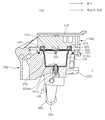
도3은 도1의 A-A'선에 따른 단면도이다.
도4는 도3에서 캡슐하우징의 안착부가 하우징덮개에 의해서 닫혔을 때의 단면도이다.
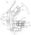
도5와 도6은 본 발명에 따른 커피캡슐 장탈착 구조의 일실시예의 작동을 나타내는 측면도이다.1 is a perspective view of an embodiment of a coffee capsule shell desorption structure according to the present invention.
2 is an exploded perspective view of an embodiment of a coffee capsule field desorption structure according to the present invention.
3 is a cross-sectional view taken along line A-A 'in Fig.
FIG. 4 is a cross-sectional view of the capsule housing of FIG. 3 when the seat is closed by the housing cover;
5 and 6 are side views illustrating the operation of an embodiment of a coffee capsule length desorption structure according to the present invention.
상기와 같은 본 발명의 특징들에 대한 이해를 돕기 위하여, 이하 본 발명의 실시예와 관련된 커피캡슐 장탈착 구조에 대하여 보다 상세하게 설명하도록 하겠다.In order to facilitate understanding of the features of the present invention as described above, the following description will discuss in more detail the structure for detaching coffee capsules according to the embodiment of the present invention.
이하, 설명되는 실시예들은 본 발명의 기술적인 특징을 이해시키기에 가장 적합한 실시예들을 기초로 하여 설명될 것이며, 설명되는 실시예들에 의해 본 발명의 기술적인 특징이 제한되는 것이 아니라, 이하, 설명되는 실시예들과 같이 본 발명이 구현될 수 있다는 것을 예시하는 것이다. 따라서, 본 발명은 아래 설명된 실시예들을 통해 본 발명의 기술 범위 내에서 다양한 변형 실시가 가능하며, 이러한 변형 실시예는 본 발명의 기술 범위 내에 속한다 할 것이다. 그리고, 이하, 설명되는 실시예의 이해를 돕기 위하여 첨부된 도면에 기재된 부호에 있어서, 각 실시예에서 동일한 작용을 하게 되는 구성요소 중 관련된 구성요소는 동일 또는 연장 선상의 숫자로 표기하였다.Hereinafter, exemplary embodiments will be described based on embodiments best suited for understanding the technical characteristics of the present invention, and the technical features of the present invention are not limited by the illustrated embodiments, It is to be understood that the present invention may be implemented as illustrated embodiments. Therefore, it is intended that the present invention covers the modifications and variations of this invention provided they come within the scope of the appended claims and their equivalents. In order to facilitate understanding of the embodiments to be described below, in the reference numerals shown in the accompanying drawings, among the constituent elements which perform the same function in each embodiment, the related constituent elements are indicated by the same or an extension line number.
본 발명과 관련된 실시예들은 기본적으로 레버부재와 복수개의 링크부재를 사용하여 커피캡슐이 안착되도록 캡슐하우징에 형성된 안착부의 상부를 하우징덮개에 의해서 개폐하도록 구성된 것을 기초로 한다.Embodiments related to the present invention are basically constructed such that an upper portion of a seating portion formed in a capsule housing is opened and closed by a housing cover so that a coffee capsule is seated using a lever member and a plurality of link members.
도1 내지 도4에 도시된 실시예와 같이 본 발명에 따른 커피캡슐 장탈착 구조(100)는 캡슐하우징(200), 하우징덮개(300) 및, 구동부(400)를 포함하여 구성될 수 있다.1 to 4, the coffee capsule
캡슐하우징(200)에는 도1 내지 도4에 도시된 실시예와 같이 안착부(210)가 형성될 수 있다. 이러한 안착부(210)는 도시된 실시예와 같이 상부가 개방된 안착공간일 수 있다. 이에 따라, 도시된 바와 같이 분말상의 커피가 밀봉되게 들어 있는 커피캡슐(CA)을 안착부(210)의 개방된 상부를 통해서 안착부(210)에 삽입하여 안착시킬 수 있다.The
또한, 캡슐하우징(200)은 커피캡슐(CA)에서 생성된 액상의 커피가 외부로 배출되도록 구성될 수 있다. 이를 위해서, 도1 내지 도4에 도시된 실시예와 같이 캡슐하우징(200)에는 안착부(210)에 연결된 커피배출구(220)가 구비될 수 있다.Also, the
그리고, 안착부(210)에는 도3과 도4에 도시된 실시예와 같이 커피공급부재(221)가 구비될 수 있다. 커피공급부재(221)의 상부는 도시된 실시예와 같이 뾰족할 수 있다. 따라서, 도3과 도4에 도시된 바와 같이 커피캡슐(CA)이 안착부(210)에 안착되면, 커피캡슐(CA)의 하부가 커피공급부재(221)에 의해서 천공될 수 있다.The
또한, 커피공급부재(221)의 상부에는 도3과 도4에 도시된 실시예와 같이 유동구멍(221a)이 형성되고 커피공급부재(221)에는 유동구멍(221a)에 연결된 커피유로(221b)가 형성될 수 있다. 그리고, 커피공급부재(221)는 커피배출구(220)에 연결될 수 있다.3 and 4, a
이러한 구성에 의해서, 후술하고 도4에 도시된 바와 같이 하우징덮개(300)에 구비되는 온수공급부재(310)에 의해서 커피캡슐(CA)에 온수가 공급됨으로써 커피캡슐(CA)에 생성된 액상의 커피가 커피공급부재(221)의 유동구멍(221a)을 통해 커피유로(221b)에 유입될 수 있다. 그리고, 액상의 커피는 커피유로(221b)와 커피배출구(220)를 유동하여 외부로 배출될 수 있다.4, hot water is supplied to the coffee capsule CA by the hot
도1 내지 도4에 도시된 실시예와 같이 안착부(210) 둘레의 캡슐하우징(200)에는 하나 이상의 파지홈(211)이 형성될 수 있다. 도시된 실시예와 같이 2개의 파지홈(211)이 서로 마주보도록 안착부(210) 둘레의 캡슐하우징(200)에 형성될 수 있다. 이러한 파지홈(211)에 의해서, 도1과 도3 및 도6에 도시된 바와 같이 캡슐하우징(200)의 안착부(210)의 상부가 열렸을 때, 사용자가 커피캡슐(CA)을 용이하게 파지할 수 있다. 그리고, 커피캡슐(CA)을 안착부(210)에 또는 캡슐하우징의 안착부로부터 사용자가 직접 용이하게 장탈착할 수 있다.One or more
또한, 안착부(210) 둘레의 캡슐하우징(200)에는 도1 내지 도4에 도시된 실시예와 같이 제2밀봉부재(212)가 구비될 수 있다. 이러한 제2밀봉부재(212)는 안착부(210) 둘레의 캡슐하우징(200)에 형성된 제2밀봉부재홈(212a)에 삽입되어 구비될 수 있다. 이에 의해서, 전술한 바와 같이 파지홈(211)이 캡슐하우징(200)에 형성되더라도, 캡슐하우징(200)과 하우징덮개(300) 사이의 밀봉이 이루어질 수 있다.In addition, the
그리고, 도1 내지 도4에 도시된 실시예와 같이 제2밀봉부재(212)에 대응되는 위치의 하우징덮개(300)에는 가압돌기(330)가 형성될 수 있다. 이에 따라, 도4와 도5에 도시된 바와 같이 하우징덮개(300)가 안착부(210)의 상부를 닫았을 때, 하우징덮개(300)의 가압돌기(330)가 캡슐하우징(200)의 제2밀봉부재(212)를 가압할 수 있다. 그러므로, 제2밀봉부재(212)에 의한 캡슐하우징(200)과 하우징덮개(300) 사이의 밀봉이 견고하게 이루어질 수 있다.1 to 4, the
하우징덮개(300)는 도1과 도3 및 도4에 도시된 실시예와 같이 캡슐하우징(200)에 힌지연결될 수 있다. 이에 따라, 하우징덮개(300)는 도5와 도6에 도시된 바와 같이 캡슐하우징(200)의 하우징덮개(300) 힌지연결부를 중심으로 회전될 수 있다.The
도1과 도2에 도시된 실시예와 같이 캡슐하우징(200)의 상부에 하우징덮개(300)를 위한 힌지연결돌기가 형성되고 하우징덮개(300)에 캡슐하우징(200)의 하우징덮개(300)를 위한 힌지연결돌기가 삽입되는 힌지연결구멍이 형성되어 하우징덮개(300)가 캡슐하우징(200)의 상부에 힌지연결될 수 있다.A hinge connection protrusion for the
그러나, 하우징덮개(300)가 캡슐하우징(200)의 상부에 힌지연결되는 구성은 도시된 실시예에 한정되지 않고, 힌지연결되는 구성이라면 주지의 어떠한 구성이라도 가능하다.However, the structure in which the
또한, 하우징덮개(300)는 도4와 도5에 도시된 바와 같이 안착부(210)의 개방된 상부를 덮도록 구성될 수 있다.In addition, the
도1과 도3 및 도4에 도시된 실시예와 같이 하우징덮개(300)에는 온수공급부재(310)가 구비될 수 있다. 이러한 온수공급부재(310)는 연결관(도시되지 않음)에 의해서 온수공급원(도시되지 않음)에 연결될 수 있다.The
온수공급부재(310)는 도1과 도3 및 도4에 도시된 실시예와 같이 뾰족할 수 있다. 이에 따라, 도4와 도5에 도시된 바와 같이 하우징덮개(300)가 안착부(210)의 상부를 닫았을 때, 캡슐하우징(200)의 안착부(210)에 안착된 커피캡슐(CA)의 상부를 천공할 수 있다.The hot
또한, 도1 내지 도4에 도시된 실시예와 같이 온수공급부재(310)에는 온수공급구멍(311)과, 온수공급구멍(311)과 온수공급원에 연결된 온수유로(도시되지 않음)가 형성될 수 있다. 이에 따라, 온수공급원의 온수가 온수유로를 유동하여 온수공급구멍(311)을 통해 커피캡슐(CA)에 공급될 수 있다. 그리고, 이에 의해서 커피캡슐(CA)에 액상의 커피가 생성될 수 있다.1 to 4, the hot
한편, 커피캡슐(CA)에는 커피캡슐(CA)에서 생성되는 액상의 커피의 맛을 좋게 하기 위해서, 온수공급부재(310)를 통해 고압의 온수가 커피캡슐(CA)에 공급되도록 할 수도 있다.On the other hand, high-pressure hot water may be supplied to the coffee capsule CA through the hot
도1과 도3 및 도4에 도시된 실시예와 같이 하우징덮개(300)에는 제1밀봉부재(320)가 구비될 수 있다. 제1밀봉부재(320)는 도시된 실시예와 같이 하우징덮개(300)에 형성된 제1밀봉부재홈(321)에 구비될 수 있다. 이러한 제1밀봉부재(320)에 의해서 도4와 도5에 도시된 바와 같이 하우징덮개(300)가 캡슐하우징(200)의 안착부(210)의 개방된 상부를 닫았을 때, 캡슐하우징(200)과 하우징덮개(300) 사이를 1차적으로 밀봉할 수 있다.As shown in FIGS. 1, 3 and 4, the
그리고, 전술한 바와 같이 캡슐하우징(200)에 구비되는 제2밀봉부재(212)에 의해서 도4와 도5에 도시된 바와 같이 하우징덮개(300)가 안착부(210)의 상부를 닫았을 때, 캡슐하우징(200)과 하우징덮개(300) 사이가 2차적으로 밀봉될 수 있다. 이에 따라, 캡슐하우징(200)과 하우징덮개(300) 사이의 밀봉이 견고하게 이루어질 수 있다.4 and 5, when the
구동부(400)는 도1 내지 도4에 도시된 실시예와 같이 레버부재(410)와 복수개의 링크부재(420,430,440)를 포함할 수 있다. 그리고, 도5와 도6에 도시된 바와 같이 레버부재(410)의 작동에 따른 링크부재(420,430,440)의 동작에 의해서 하우징덮개(300)가 회전되도록 구성될 수 있다. 이에 따라, 캡슐하우징(200)의 장착부(210)의 상부를 도5와 도6에 도시된 바와 같이 개폐할 수 있다. 그리고, 커피캡슐(CA)을 안착부(210)에 또는 안착부(210)로부터 사용자가 직접 용이하게 장탈착할 수 있다.The driving
이와 같이, 커피캡슐(CA)을 사용자가 직접 안착부(210)에 또는 안착부(210)로부터 장탈착할 수 있기 때문에, 안착부(210)에 커피캡슐(CA)을 장탈착하기 위한 구성을 구비할 필요가 없게 된다. 따라서, 안착부(210)에 커피캡슐(CA) 장탈착용 구성을 위한 공간이 없어도 되어, 안착부(210)의 밀봉이 잘 이루어질 수 있다. 그러므로, 안착부(210)에 액상의 커피 등의 남지 않게 되어 오염되지 않을 수 있어서 위생성이 향상될 수 있다.As described above, since the coffee capsule CA can be directly attached to and detached from the
도4와 도5에 도시된 바와 같이 하우징덮개(300)에 의해서 캡슐하우징(200)의 안착부(210)의 상부가 닫힌 상태에서, 구동부(400)는 안착부(210)에 고압이 작용하여도, 예컨대 전술한 바와 같이 커피캡슐(CA)에 고압이 온수가 공급되어 안착부(210)에 고압이 작용하여도 하우징덮개(300)가 열리지 않도록 구성될 수 있다.4 and 5, when the upper portion of the
이를 위해서, 구동부(400)는 도1 내지 도4에 도시된 실시예와 같이 레버부재(410), 회전링크부재(420), 제1연결링크부재(430) 및, 제2연결링크부재(440)를 포함할 수 있다.To this end, the driving
도1과 도5 및 도6에 도시된 실시예와 같이 레버부재(410)는 캡슐하우징(200)의 상부에 힌지연결될 수 있다. 이에 따라, 레버부재(410)는 도5와 도6에 도시된 바와 같이 캡슐하우징(200)의 레버부재(410) 힌지연결부를 중심으로 회전될 수 있다.The
캡슐하우징(200)의 상부에 레버부재(410)를 위한 힌지연결돌기가 도1과 도2에 도시된 실시에와 같이 형성되고 레버부재(410)에 캡슐하우징(200)의 레버부재(410)를 위한 힌지연결돌기가 삽입되는 힌지연결구멍이 형성되어 레버부재(410)가 캡슐하우징(200)의 상부에 힌지연결될 수 있다.A hinge connection protrusion for the
그러나, 레버부재(410)가 캡슐하우징(200)의 상부에 힌지연결되는 구성은 도시된 실시예에 한정되지 않고, 힌지연결되는 구성이라면 주지의 어떠한 구성이라도 가능하다.However, the structure in which the
회전링크부재(420)는 도1과 도5 및 도6에 도시된 실시예와 같이 일측이 캡슐하우징(200)의 하부에 힌지연결될 수 있다. 이에 따라, 도5와 도6에 도시된 바와 같이 회전링크부재(420)는 일측을 중심으로 회전될 수 있다.The
도1과 도5 및 도6에 도시된 실시예와 같이 회전링크부재(420)의 일측에는 힌지연결돌기가 형성되고 캡슐하우징(200)의 하부에는 회전링크부재(420)의 힌지연결돌기가 삽입되는 힌지연결구멍이 형성되어 회전링크부재(420)의 일측이 캡슐하우징(200)의 하부에 힌지연결될 수 있다.A hinge connection protrusion is formed on one side of the
그러나, 회전링크부재(420)의 일측이 캡슐하우징(200)의 하부에 힌지연결되는 구성은 이에 한정되지 않고, 힌지연결되는 구성이라면 주지의 어떠한 구성이라도 가능하다.However, the configuration in which one side of the
제1연결링크부재(430)의 일측은 도1과 도5 및 도6에 도시된 실시예와 같이 하우징덮개(300)에 힌지연결될 수 있다. 그리고, 제1연결링크부재(430)의 타측은 회전링크부재(420)의 타측에 힌지연결될 수 있다. 이에 따라, 도5와 도6에 도시된 바와 같이 회전링크부재(420)의 회전에 의해서 제1연결링크부재(430)가 이동하여 하우징덮개(300)가 회전되도록 할 수 있다.One side of the first connecting
도1과 도5 및 도6에 도시된 실시예와 같이 하우징덮개(300)에는 힌지연결돌기가 형성되고 제1연결링크부재(430)의 일측에는 하우징덮개(300)의 힌지연결돌기가 삽입되는 힌지연결구멍이 형성되어 제1연결링크부재(430)의 일측이 하우징덮개(300)에 힌지연결될 수 있다. 또한, 회전링크부재(420)의 타측에는 힌지연결돌기가 형성되고 제1연결부재(430)의 타측에는 회전링크부재(420)의 타측의 힌지연결돌기 삽입되는 힌지연결구멍이 형성되어 제1연결링크부재(430)의 타측이 회전링크부재(420)의 타측에 힌지연결될 수 있다.1, 5 and 6, a hinge connection protrusion is formed on the
그러나, 제1연결링크부재(430)의 일측이 하우징덮개(300)에 힌지연결되고 타측이 회전링크부재(420)의 타측에 힌지연결되는 구성은 도시된 실시예에 한정되지 않고, 힌지연결되는 구성이라면 주지의 어떠한 구성이라도 가능하다.However, the structure in which one side of the first connecting
한편, 도1과 도2에 도시된 실시예와 같이 제1연결링크부재(430)에는 걸림홈(431)이 형성될 수 있다. 이러한 걸림홈(431)은 도5에 도시된 바와 같이 하우징덮개(300)가 안착부(210)의 상부를 닫았을 때 캡슐하우징(200)에 형성된 걸림턱(230)에 걸릴 수 있다. 이에 의해서, 하우징덮개(300)가 안착부(210)의 상부를 닫았을 때, 하우징덮개(300)가 후술할 바와 같이 레버부재(410)에 의하지 아니하면 위로 들어올려지지 아니할 수 있다.1 and 2, the first
제2연결링크부재(440)의 일측은 도1과 도5 및 도6에 도시된 실시예와 같이 레버부재(410)에 힌지연결될 수 있다. 그리고, 제2연결링크부재(440)의 타측은 회전링크부재(420)의 타측에 힌지연결될 수 있다. 이에 따라, 도5와 도6에 도시된 바와 같이 레버부재(410)의 작동에 의해서 제2연결링크부재(440)가 이동하여 회전링크부재(420)가 회전되도록 할 수 있다.One side of the second connecting
도1과 도5 및 도6에 도시된 실시예와 같이 레버부재(410)에는 힌지연결돌기가 형성되고 제2연결링크부재(440)의 일측에는 레버부재(410)의 힌지연결돌기가 삽입되는 힌지연결구멍이 형성되어 제2연결링크부재(440)의 일측이 레버부재(410)에 힌지연결될 수 있다. 또한, 제2연결링크부재(440)의 타측에는 회전링크부재(420)의 타측에 형성된 힌지연결돌기가 삽입되는 힌지연결구멍이 형성되어 제2연결링크부재(440)의 타측이 회전링크부재(420)의 타측에 힌지연결될 수 있다.The
그러나, 제2연결링크부재(440)의 일측이 레버부재(410)에 힌지연결되고 타측이 회전링크부재(420)의 타측에 힌지연결되는 구성은 도시된 실시예에 한정되지 않고, 힌지연결되는 구성이라면 주지의 어떠한 구성이라도 가능하다.However, the configuration in which one side of the second connecting
회전링크부재(420)는 도1과 도5 및 도6에 도시된 실시예와 같이 제1연결링크부재(430)와 제2연결링크부재(440)보다 길이가 짧을 수 있다. 이에 따라, 도5와 도6에 도시된 바와 같이 레버부재(410)의 작동에 의해서 제1연결링크부재(430)가 이동하고 회전링크부재(420)가 회전하며 제2연결링크부재(440)가 이동하여 하우징덮개(300)가 회전될 수 있다. 이에 의해서, 하우징덮개(300)가 캡슐하우징(200)의 안착부(210)의 상부를 개폐할 수 있다.The
한편, 도5에 도시된 바와 같이 하우징덮개(300)가 안착부(210)의 상부를 닫았을 때, 회전링크부재(420)의 일측에서 타측으로 연장된 제1중심가상선(L1)은 제1연결링크부재(430)의 일측에서 타측으로 연장된 제2중심가상선(L2)과 제2연결링크부재(440)의 일측에서 타측으로 연장된 제3중심가상선(L3) 사이에 위치할 수 있다.5, when the
이에 따라, 레버부재(410)를 올렸을 때, 제2연결링크부재(440)의 이동으로 인한 회전링크부재(420)의 회전방향과, 캡슐하우징(200)의 안착부(210)에 고압이 작용하여 하우징덮개(300)을 올리는 힘에 의해서 제1연결링크부재(430)의 이동으로 인한 회전링크부재(420)의 회전방향이 다를 수 있다.The rotation direction of the
또한, 제3중심가상선(L3)은 제2중심가상선(L2)보다 레버부재(410)의 힌지연결부에 가깝게 위치할 수 있다.In addition, the third center-gravity line L3 may be positioned closer to the hinge connection portion of the
따라서, 도5에 도시된 바와 같이 하우징덮개(300)에 의해서 캡슐하우징(200)의 안착부(210)의 상부가 닫혔을 때, 레버부재(410)를 들어올리면, 제2연결링크부재(440)가 레버부재(410)의 힌지연결부 측으로 이동하여 회전링크부재(420)가 도면에서 보아 시계방향으로 회전될 수 있다. 그러므로, 제1연결링크부재(430)에 의해서 하우징덮개(300)가 열릴 수 있다.5, when the upper portion of the
그리고, 하우징덮개(300)에 의해서 캡슐하우징(200)의 안착부(210)의 상부가 도5에 도시된 바와 같이 닫혔을 때, 캡슐하우징(200)의 안착부(210)에 고압이 작용하면, 하우징덮개(300)가 들어올려지는 방향으로 힘이 작용하게 된다. 이에 따라, 제1연결링크부재(430)가 레버부재(410)의 힌지연결부로부터 멀어지는 방향으로 제1연결링크부재(430)에 힘이 작용할 수 있다. 그리고, 회전링크부재(420)가 도면에서 보아 반시계방향으로 회전되는 방향으로 회전링크부재(420)에 힘이 작용할 수 있다. 그러므로, 하우징덮개(300)가 제1연결링크부재(430)에 의해서 캡슐하우징(200)의 안착부(210)의 상부를 더 닫을 수 있다.
When the upper portion of the
이상에서와 같이 본 발명에 따른 커피캡슐 장탈착 구조를 사용하면, 레버부재와 복수개의 링크부재를 사용하여 커피캡슐이 안착되도록 캡슐하우징에 형성된 안착부의 상부를 하우징덮개에 의해서 개폐할 수 있으며, 커피캡슐을 캡슐하우징의 안착부에 또는 캡슐하우징의 안착부로부터 사용자가 직접 용이하게 장탈착할 수 있고, 안착부에 커피캡슐 장탈착을 위한 구성이 구비되지 않기 때문에 안착부의 밀봉이 잘 이루어질 수 있으며, 안착부에 액상의 커피 등이 남지 않게 되어 안착부가 오염되지 않을 수 있고 위생성이 향상될 수 있다.
As described above, according to the present invention, it is possible to open and close the upper part of the seating part formed in the capsule housing by using the housing cover so that the coffee capsule is seated using the lever member and the plurality of link members, The user can easily and conveniently remove the capsule from the seating portion of the capsule housing or from the seating portion of the capsule housing and the seating portion can be well sealed because no configuration for removing the coffee cap is provided in the seating portion, Liquid coffee or the like is not left on the seating portion, so that the seating portion can be prevented from being contaminated and the hygiene can be improved.
상기와 같이 설명된 커피캡슐 장탈착 구조는 상기 설명된 실시예의 구성이 한정되게 적용될 수 있는 것이 아니라, 상기 실시예들은 다양한 변형이 이루어질 수 있도록 각 실시예들의 전부 또는 일부가 선택적으로 조합되어 구성될 수도 있다.
The above-described coffee capillary bowl desorption structure is not limited to the configuration of the above-described embodiments, but all or a part of the embodiments may be selectively combined so that various modifications may be made to the embodiments It is possible.
100 : 커피캡슐 장탈착 구조200 : 캡슐하우징
210 : 안착부211 : 파지홈
212 : 제2밀봉부재212a : 제2밀봉부재홈
220 : 커피배출구221 : 커피공급부재
221a : 유동구멍221b : 커피유로
300 : 하우징덮개310 : 온수공급부재
311 : 온수공급구멍320 : 제1밀봉부재
321 : 제1밀봉부재홈330 : 가압돌기
400 : 구동부410 : 레버부재
420 : 회전링크부재430 : 제1연결링크부재
440 : 제2연결링크부재CA : 커피캡슐
L1 : 제1중심가상선L2 : 제2중심가상선
L3 : 제3중심가상선100: Capsule detachable structure 200: Capsule housing
210: seat part 211: gripping groove
212: second sealing
220: coffee outlet 221: coffee supply member
221a:
300: housing cover 310: hot water supply member
311: hot water supply hole 320: first sealing member
321: first sealing member groove 330: pressing projection
400: driving part 410: lever member
420: rotating link member 430: first connecting link member
440: second connection link member CA: coffee capsule
L1: first center-of-gravity image line L2: second center-
L3: Third central merchant line
Claims (13)
Translated fromKorean상기 캡슐하우징(200)에 힌지연결되며 상기 안착부(210)의 개방된 상부를 덮도록 구성된 하우징덮개(300); 및
레버부재(410)와 복수개의 링크부재(420,430,440)를 포함하며 상기 레버부재(410)의 작동에 따른 링크부재(420,430,440)의 동작에 의해서 상기 하우징덮개(300)가 회전되도록 구성되어 상기 안착부(210)의 상부를 개폐하는 구동부(400);
를 포함하여 구성된 커피캡슐 장탈착 구조.A capsule housing (200) in which a seating part (210) on which a coffee capsule (CA) containing powdered coffee is sealed is formed and a liquid coffee produced in the coffee capsule (CA) is discharged to the outside;
A housing cover (300) hinged to the capsule housing (200) and configured to cover an open top of the seating part (210); And
The housing cover 300 is configured to be rotated by the operation of the link members 420, 430 and 440 according to the operation of the lever member 410 including the lever member 410 and the plurality of link members 420, 430 and 440, 210);
Wherein the coffee capillary detachment structure comprises:
상기 캡슐하우징(200)의 상부에 힌지연결되는 레버부재(410);
일측이 상기 캡슐하우징(200)의 하부에 힌지연결되는 회전링크부재(420);
일측은 상기 하우징덮개(300)에 힌지연결되고 타측은 상기 회전링크부재(420)의 타측에 힌지연결되는 제1연결링크부재(430); 및
일측은 상기 레버부재(410)에 힌지연결되고 타측은 상기 회전링크부재(420)의 타측에 힌지연결되는 제2연결링크부재(440); 를 포함하는 것을 특징으로 하는 커피캡슐 장탈착 구조.3. The apparatus of claim 2, wherein the driving unit (400)
A lever member 410 hinged to the upper portion of the capsule housing 200;
A rotary link member 420 having one side hinged to the lower portion of the capsule housing 200;
A first connecting link member 430 hinged to the housing cover 300 at one side and hinged to the other side of the rotating link member 420 at the other side; And
A second connecting link member (440) hinged to the lever member (410) at one side and hinged to the other side of the rotating link member (420) at the other side; Wherein the coffee capsules are arranged in a plurality of rows.
상기 안착부(210)에는 커피캡슐(CA)에서 생성된 액상의 커피가 상기 커피배출구(220)로 유동하도록 상기 안착부(210)에 안착된 커피캡슐(CA)의 하부를 천공하며 상기 커피배출구(220)에 연결되는 커피공급부재(221)가 구비되는 것을 특징으로 하는 커피캡슐 장탈착 구조.[3] The apparatus according to claim 1, wherein the capsule housing (200) is provided with a coffee outlet (220) connected to the seating part (210)
The seating part 210 punctures the lower part of the coffee capsule CA seated on the seating part 210 so that the liquid coffee produced in the coffee capsule CA flows to the coffee outlet 220, And a coffee supply member (221) connected to the coffee bag (220).
13. The method of claim 12, wherein the housing lid (300) at a position corresponding to the second sealing member (212) is formed with a pressing projection (330) for pressing the second sealing member (212) Desorption structure.
Priority Applications (4)
| Application Number | Priority Date | Filing Date | Title |
|---|---|---|---|
| KR1020120126732AKR102064177B1 (en) | 2012-11-09 | 2012-11-09 | Coffee capsule mounting/dismounting structure |
| PCT/KR2013/009875WO2014073822A1 (en) | 2012-11-09 | 2013-11-04 | Coffee capsule mounting and removal structure |
| CN201380058027.XACN104780817B (en) | 2012-11-09 | 2013-11-04 | Coffee capsule mounting and removal structure |
| EP13852909.4AEP2918198B1 (en) | 2012-11-09 | 2013-11-04 | Coffee capsule mounting and removal structure |
Applications Claiming Priority (1)
| Application Number | Priority Date | Filing Date | Title |
|---|---|---|---|
| KR1020120126732AKR102064177B1 (en) | 2012-11-09 | 2012-11-09 | Coffee capsule mounting/dismounting structure |
Publications (2)
| Publication Number | Publication Date |
|---|---|
| KR20140060410Atrue KR20140060410A (en) | 2014-05-20 |
| KR102064177B1 KR102064177B1 (en) | 2020-01-09 |
Family
ID=50684870
Family Applications (1)
| Application Number | Title | Priority Date | Filing Date |
|---|---|---|---|
| KR1020120126732AActiveKR102064177B1 (en) | 2012-11-09 | 2012-11-09 | Coffee capsule mounting/dismounting structure |
Country Status (4)
| Country | Link |
|---|---|
| EP (1) | EP2918198B1 (en) |
| KR (1) | KR102064177B1 (en) |
| CN (1) | CN104780817B (en) |
| WO (1) | WO2014073822A1 (en) |
Cited By (4)
| Publication number | Priority date | Publication date | Assignee | Title |
|---|---|---|---|---|
| WO2016039543A1 (en)* | 2014-09-12 | 2016-03-17 | 코웨이 주식회사 | Beverage extracting device and water purifier including same |
| KR20160031687A (en)* | 2014-09-12 | 2016-03-23 | 코웨이 주식회사 | Beverage extracting apparatus |
| KR20160039093A (en)* | 2014-09-30 | 2016-04-08 | 코웨이 주식회사 | Beverage extracting apparatus and water purifier including the same |
| KR20180010865A (en)* | 2016-07-22 | 2018-01-31 | 엘지전자 주식회사 | Coffee extraction device |
Families Citing this family (7)
| Publication number | Priority date | Publication date | Assignee | Title |
|---|---|---|---|---|
| EP3143911A1 (en)* | 2015-09-17 | 2017-03-22 | Mocoffee AG | Apparatus for producing a beverage from a capsule |
| CN108784360B (en)* | 2018-07-30 | 2023-10-31 | 宁波三A集团电器有限公司 | Coffee machine brewing structure with fool-proof function |
| US12171361B2 (en) | 2020-12-30 | 2024-12-24 | Sharkninja Operating Llc | Hybrid receptacle beverage brewing system |
| CN115191832A (en)* | 2022-07-29 | 2022-10-18 | 广东亿龙电器科技有限公司 | Electric brewing device |
| USD1048792S1 (en) | 2023-04-12 | 2024-10-29 | Sharkninja Operating Llc | Coffee machine |
| USD1048793S1 (en) | 2023-05-02 | 2024-10-29 | Sharkninja Operating Llc | Coffee machine |
| KR102594263B1 (en) | 2023-05-31 | 2023-10-27 | (주)하나프리 | Capsule coffee extraction basket compatible with various coffee machines |
Family Cites Families (14)
| Publication number | Priority date | Publication date | Assignee | Title |
|---|---|---|---|---|
| US7146904B2 (en) | 2004-01-06 | 2006-12-12 | Whirlpool Corporation | Top load coffee maker with front access water reservoir |
| DK1702543T3 (en) | 2004-10-25 | 2008-01-07 | Nestec Sa | Capsule with sealants |
| PT1853142E (en)* | 2005-02-07 | 2009-05-05 | Nestec Sa | Device for preparing a drink from a capsule by injection of a pressurized fluid and capsule-holder adapted therefore |
| WO2007016977A1 (en)* | 2005-08-05 | 2007-02-15 | Delica Ag | Device for extracting an extraction product contained in a capsule by means of a liquid extraction agent |
| DE602006009232D1 (en)* | 2006-05-24 | 2009-10-29 | Nestec Sa | Brewing device for capsule with locking mechanism with variable transmission ratio |
| US8573114B2 (en)* | 2006-09-07 | 2013-11-05 | Keurig, Incorporated | Method and apparatus for beverage formation with liquid delivery control |
| ITFI20070028A1 (en)* | 2007-02-07 | 2008-08-08 | Saeco Ipr Ltd | INFUSION DEVICE FOR THE PREPARATION OF DRINKS FROM SINGLE-DOSE CAPSULES WITH A CAPSULES CENTERING DEVICE. |
| CA2688310C (en)* | 2007-06-05 | 2015-11-17 | Nestec S.A. | Method for preparing a beverage or liquid food and system using brewing centrifugal force |
| ITFI20070267A1 (en)* | 2007-11-28 | 2009-05-29 | Saeco Ipr Ltd | "INFUSION GROUP FOR THE PREPARATION OF DRINKS FROM SINGLE-DOSE PACKAGES AND MACHINE INCLUDING THE GROUP" |
| EP2238878A1 (en)* | 2009-04-09 | 2010-10-13 | Nestec S.A. | Beverage preparation device having a closing mechanism with force demultiplying means |
| IT1395049B1 (en)* | 2009-08-10 | 2012-09-05 | Capitani Srl | INFUSION GROUP |
| IT1396016B1 (en)* | 2009-10-15 | 2012-11-09 | Swiss Caffe Asia Ltd | INFUSION DEVICE FOR INFUSION AND SIMILAR CAPSULES, PARTICULARLY FOR ESPRESSO AND SIMILAR COFFEE MACHINES. |
| CN201727359U (en)* | 2010-05-07 | 2011-02-02 | 漳州灿坤实业有限公司 | Extraction mechanism of coffee capsule |
| JP5909494B2 (en)* | 2010-10-08 | 2016-04-26 | コーニンクレッカ フィリップス エヌ ヴェKoninklijke Philips N.V. | Extraction unit using horizontal motion |
- 2012
- 2012-11-09KRKR1020120126732Apatent/KR102064177B1/enactiveActive
- 2013
- 2013-11-04EPEP13852909.4Apatent/EP2918198B1/enactiveActive
- 2013-11-04WOPCT/KR2013/009875patent/WO2014073822A1/enactiveApplication Filing
- 2013-11-04CNCN201380058027.XApatent/CN104780817B/enactiveActive
Cited By (5)
| Publication number | Priority date | Publication date | Assignee | Title |
|---|---|---|---|---|
| WO2016039543A1 (en)* | 2014-09-12 | 2016-03-17 | 코웨이 주식회사 | Beverage extracting device and water purifier including same |
| KR20160031687A (en)* | 2014-09-12 | 2016-03-23 | 코웨이 주식회사 | Beverage extracting apparatus |
| US10973365B2 (en) | 2014-09-12 | 2021-04-13 | Coway Co., Ltd | Beverage extracting device and water purifier including same |
| KR20160039093A (en)* | 2014-09-30 | 2016-04-08 | 코웨이 주식회사 | Beverage extracting apparatus and water purifier including the same |
| KR20180010865A (en)* | 2016-07-22 | 2018-01-31 | 엘지전자 주식회사 | Coffee extraction device |
Also Published As
| Publication number | Publication date |
|---|---|
| CN104780817A (en) | 2015-07-15 |
| WO2014073822A8 (en) | 2015-05-07 |
| EP2918198A1 (en) | 2015-09-16 |
| WO2014073822A1 (en) | 2014-05-15 |
| EP2918198B1 (en) | 2020-01-08 |
| KR102064177B1 (en) | 2020-01-09 |
| CN104780817B (en) | 2017-05-10 |
| EP2918198A4 (en) | 2015-11-25 |
Similar Documents
| Publication | Publication Date | Title |
|---|---|---|
| KR20140060410A (en) | Coffee capsule mounting/dismounting structure | |
| KR102449623B1 (en) | Capsule coffee extraction device | |
| KR20160031686A (en) | Beverage extracting apparatus and water purifier including the same | |
| KR20110053368A (en) | Coffee holding arm of hand loading coffee machine | |
| KR101572956B1 (en) | Beverage maker for all cartridge | |
| KR102533256B1 (en) | Filter fixing unit and water purifier having thereof | |
| WO2003059778A3 (en) | Closed capsule with opening mean | |
| PT1702543E (en) | Capsule with sealing means | |
| CN106742648B (en) | A kind of lid of rotating opening | |
| CN217610860U (en) | Sewage filter box of ground cleaning equipment and sewage box structure thereof | |
| CN204931152U (en) | One is made tea thermos cup | |
| KR101448275B1 (en) | Beverage maker equipped with separator cartridge | |
| KR101648624B1 (en) | Cartridge for infusing beverage and device for both infusing beverage using the same | |
| KR20110009651U (en) | Portable dripper and beverage vessel with the same | |
| CN101336792B (en) | Filter coffee-maker comprising a removable filter holder | |
| KR20140073329A (en) | Coffee capsule mounting/dismounting structure | |
| KR101854864B1 (en) | Portable device for extracting coffee from coffee capsule | |
| JP2012157432A (en) | Beverage container | |
| KR20140126793A (en) | Beverage discharging structure of beverge capsule | |
| TWI534046B (en) | Anti-drip with cap | |
| KR101289339B1 (en) | Extraction apparatus of beverage | |
| CN105708116B (en) | The outdoor kettle of one | |
| CN207744711U (en) | A kind of electronic cigarette | |
| KR20150066189A (en) | Receptacle universal beverage maker | |
| CN101648619A (en) | Sliding pin type incorrect opening preventing container cover |
Legal Events
| Date | Code | Title | Description |
|---|---|---|---|
| PA0109 | Patent application | Patent event code:PA01091R01D Comment text:Patent Application Patent event date:20121109 | |
| PG1501 | Laying open of application | ||
| A201 | Request for examination | ||
| PA0201 | Request for examination | Patent event code:PA02012R01D Patent event date:20171108 Comment text:Request for Examination of Application Patent event code:PA02011R01I Patent event date:20121109 Comment text:Patent Application | |
| E902 | Notification of reason for refusal | ||
| PE0902 | Notice of grounds for rejection | Comment text:Notification of reason for refusal Patent event date:20190528 Patent event code:PE09021S01D | |
| E701 | Decision to grant or registration of patent right | ||
| PE0701 | Decision of registration | Patent event code:PE07011S01D Comment text:Decision to Grant Registration Patent event date:20191119 | |
| GRNT | Written decision to grant | ||
| PR0701 | Registration of establishment | Comment text:Registration of Establishment Patent event date:20200103 Patent event code:PR07011E01D | |
| PR1002 | Payment of registration fee | Payment date:20200106 End annual number:3 Start annual number:1 | |
| PG1601 | Publication of registration | ||
| PR1001 | Payment of annual fee | Payment date:20231226 Start annual number:5 End annual number:5 | |
| PR1001 | Payment of annual fee | Payment date:20241224 Start annual number:6 End annual number:6 |