KR20140055943A - Led lighting device - Google Patents
Led lighting deviceDownload PDFInfo
- Publication number
- KR20140055943A KR20140055943AKR1020130073097AKR20130073097AKR20140055943AKR 20140055943 AKR20140055943 AKR 20140055943AKR 1020130073097 AKR1020130073097 AKR 1020130073097AKR 20130073097 AKR20130073097 AKR 20130073097AKR 20140055943 AKR20140055943 AKR 20140055943A
- Authority
- KR
- South Korea
- Prior art keywords
- case
- led
- light
- present
- case portion
- Prior art date
- Legal status (The legal status is an assumption and is not a legal conclusion. Google has not performed a legal analysis and makes no representation as to the accuracy of the status listed.)
- Ceased
Links
Images


Classifications
- F—MECHANICAL ENGINEERING; LIGHTING; HEATING; WEAPONS; BLASTING
- F21—LIGHTING
- F21V—FUNCTIONAL FEATURES OR DETAILS OF LIGHTING DEVICES OR SYSTEMS THEREOF; STRUCTURAL COMBINATIONS OF LIGHTING DEVICES WITH OTHER ARTICLES, NOT OTHERWISE PROVIDED FOR
- F21V7/00—Reflectors for light sources
- F21V7/04—Optical design
- F—MECHANICAL ENGINEERING; LIGHTING; HEATING; WEAPONS; BLASTING
- F21—LIGHTING
- F21S—NON-PORTABLE LIGHTING DEVICES; SYSTEMS THEREOF; VEHICLE LIGHTING DEVICES SPECIALLY ADAPTED FOR VEHICLE EXTERIORS
- F21S8/00—Lighting devices intended for fixed installation
- F21S8/02—Lighting devices intended for fixed installation of recess-mounted type, e.g. downlighters
- F—MECHANICAL ENGINEERING; LIGHTING; HEATING; WEAPONS; BLASTING
- F21—LIGHTING
- F21S—NON-PORTABLE LIGHTING DEVICES; SYSTEMS THEREOF; VEHICLE LIGHTING DEVICES SPECIALLY ADAPTED FOR VEHICLE EXTERIORS
- F21S8/00—Lighting devices intended for fixed installation
- F21S8/03—Lighting devices intended for fixed installation of surface-mounted type
- F—MECHANICAL ENGINEERING; LIGHTING; HEATING; WEAPONS; BLASTING
- F21—LIGHTING
- F21S—NON-PORTABLE LIGHTING DEVICES; SYSTEMS THEREOF; VEHICLE LIGHTING DEVICES SPECIALLY ADAPTED FOR VEHICLE EXTERIORS
- F21S8/00—Lighting devices intended for fixed installation
- F21S8/04—Lighting devices intended for fixed installation intended only for mounting on a ceiling or the like overhead structures
- F21S8/06—Lighting devices intended for fixed installation intended only for mounting on a ceiling or the like overhead structures by suspension
- F—MECHANICAL ENGINEERING; LIGHTING; HEATING; WEAPONS; BLASTING
- F21—LIGHTING
- F21V—FUNCTIONAL FEATURES OR DETAILS OF LIGHTING DEVICES OR SYSTEMS THEREOF; STRUCTURAL COMBINATIONS OF LIGHTING DEVICES WITH OTHER ARTICLES, NOT OTHERWISE PROVIDED FOR
- F21V21/00—Supporting, suspending, or attaching arrangements for lighting devices; Hand grips
- F21V21/14—Adjustable mountings
- F21V21/30—Pivoted housings or frames
- F—MECHANICAL ENGINEERING; LIGHTING; HEATING; WEAPONS; BLASTING
- F21—LIGHTING
- F21V—FUNCTIONAL FEATURES OR DETAILS OF LIGHTING DEVICES OR SYSTEMS THEREOF; STRUCTURAL COMBINATIONS OF LIGHTING DEVICES WITH OTHER ARTICLES, NOT OTHERWISE PROVIDED FOR
- F21V23/00—Arrangement of electric circuit elements in or on lighting devices
- F21V23/02—Arrangement of electric circuit elements in or on lighting devices the elements being transformers, impedances or power supply units, e.g. a transformer with a rectifier
- F21V23/023—Power supplies in a casing
- F—MECHANICAL ENGINEERING; LIGHTING; HEATING; WEAPONS; BLASTING
- F21—LIGHTING
- F21V—FUNCTIONAL FEATURES OR DETAILS OF LIGHTING DEVICES OR SYSTEMS THEREOF; STRUCTURAL COMBINATIONS OF LIGHTING DEVICES WITH OTHER ARTICLES, NOT OTHERWISE PROVIDED FOR
- F21V7/00—Reflectors for light sources
- F21V7/0008—Reflectors for light sources providing for indirect lighting
- F—MECHANICAL ENGINEERING; LIGHTING; HEATING; WEAPONS; BLASTING
- F21—LIGHTING
- F21V—FUNCTIONAL FEATURES OR DETAILS OF LIGHTING DEVICES OR SYSTEMS THEREOF; STRUCTURAL COMBINATIONS OF LIGHTING DEVICES WITH OTHER ARTICLES, NOT OTHERWISE PROVIDED FOR
- F21V7/00—Reflectors for light sources
- F21V7/0025—Combination of two or more reflectors for a single light source
- F21V7/0033—Combination of two or more reflectors for a single light source with successive reflections from one reflector to the next or following
- F21V7/0041—Combination of two or more reflectors for a single light source with successive reflections from one reflector to the next or following for avoiding direct view of the light source or to prevent dazzling
- F—MECHANICAL ENGINEERING; LIGHTING; HEATING; WEAPONS; BLASTING
- F21—LIGHTING
- F21V—FUNCTIONAL FEATURES OR DETAILS OF LIGHTING DEVICES OR SYSTEMS THEREOF; STRUCTURAL COMBINATIONS OF LIGHTING DEVICES WITH OTHER ARTICLES, NOT OTHERWISE PROVIDED FOR
- F21V7/00—Reflectors for light sources
- F21V7/005—Reflectors for light sources with an elongated shape to cooperate with linear light sources
- F—MECHANICAL ENGINEERING; LIGHTING; HEATING; WEAPONS; BLASTING
- F21—LIGHTING
- F21Y—INDEXING SCHEME ASSOCIATED WITH SUBCLASSES F21K, F21L, F21S and F21V, RELATING TO THE FORM OR THE KIND OF THE LIGHT SOURCES OR OF THE COLOUR OF THE LIGHT EMITTED
- F21Y2103/00—Elongate light sources, e.g. fluorescent tubes
- F21Y2103/10—Elongate light sources, e.g. fluorescent tubes comprising a linear array of point-like light-generating elements
- F—MECHANICAL ENGINEERING; LIGHTING; HEATING; WEAPONS; BLASTING
- F21—LIGHTING
- F21Y—INDEXING SCHEME ASSOCIATED WITH SUBCLASSES F21K, F21L, F21S and F21V, RELATING TO THE FORM OR THE KIND OF THE LIGHT SOURCES OR OF THE COLOUR OF THE LIGHT EMITTED
- F21Y2115/00—Light-generating elements of semiconductor light sources
- F21Y2115/10—Light-emitting diodes [LED]
Landscapes
- Engineering & Computer Science (AREA)
- General Engineering & Computer Science (AREA)
- Power Engineering (AREA)
- Non-Portable Lighting Devices Or Systems Thereof (AREA)
- Fastening Of Light Sources Or Lamp Holders (AREA)
- Arrangement Of Elements, Cooling, Sealing, Or The Like Of Lighting Devices (AREA)
Abstract
Translated fromKoreanDescription
Translated fromKorean본 발명은 엘이디 조명장치에 관한 것으로, 보다 상세하게는 확장성과 범용성을 향상시킬 수 있는 엘이디 조명장치에 관한 것이다.
BACKGROUND OF THE
일반적으로 엘이디를 이용한 실내 조명장치는 일반적인 소켓형 전구를 대체하기 위한 벌브형의 조명장치와 형광등을 대체하기 위한 면조명 장치로 크게 구분할 수 있다.In general, an indoor lighting device using LEDs can be broadly classified into a bulb-type lighting device for replacing a general socket-type bulb and a surface lighting device for replacing a fluorescent lamp.
그 중 면조명 장치는 일정 면적의 확산판을 커버로 사용하는 것이 대부분이며, 그 예로 등록특허 10-0998980호(등록일자 2010년 12월 1일)를 들 수 있다. 상기 등록특허의 대표도면인 도 4에는 상향으로 광을 방출하도록 다수의 엘이디가 배치된 기판을 실장하고, 그 기판의 상부측에 적어도 한 층 이상의 확산층이 포함되도록 하여, 다수의 엘이디에서 방출된 광들을 확산시켜 특정한 크기의 면 전체에서 일정한 조도로 조명할 수 있도록 한 구성이다.
Among them, most of the surface lighting devices use a diffusion plate having a predetermined area as a cover, for example, Registration No. 10-0998980 (registered on Dec. 1, 2010). 4, which is a representative drawing of the above-mentioned patent, includes a substrate on which a plurality of LEDs are arranged to emit light upward, and at least one diffusion layer is included on the upper side of the substrate, So as to illuminate the entire surface of a specific size with a uniform illumination.
이와 같은 구성은 일반적인 면 조명 장치에서 흔히 사용하는 방법으로, 확산판은 광이 일부에서 집중적으로 방출되는 것을 방지하여 눈부심의 발생을 방지하는 효과가 있으나, 광 손실이 많아 광효율이 저하되는 문제점이 있었다.
Such a configuration is a method commonly used in a general planar illumination device. The diffusion plate prevents the light from being partially emitted intensively, thereby preventing the occurrence of glare, but there is a problem in that the light efficiency is lowered due to a large optical loss .
이러한 이유로 충분한 조도의 면광원을 제공하기 위해서는 필요 이상으로 많은 수의 엘이디를 사용해야 하기 때문에 엘이디 조명의 저전력소모라는 장점이 퇴색하게 되며, 엘이디에서 방출되는 열을 처리하기가 용이하지 않아 그 열에 의해 엘이디의 수명이 단축될 수 있는 문제점이 있었다.
For this reason, it is necessary to use a larger number of LEDs than necessary in order to provide a planar light source of sufficient illuminance, so that the advantage of low power consumption of the LED illumination is reduced and it is not easy to handle heat emitted from the LED, There is a problem in that the life of the battery can be shortened.
아울러 상기 등록특허의 도 4에 도시된 면발광장치의 경우에는 동일한 출력의 엘이디 칩을 사용한다는 가정하에 종래 40와트(W)급의 조명장치에서 20와트(W)급으로 설계를 변경하게 되면, 케이스의 설계를 반드시 변경해야 하는 문제점이 있었다.In addition, in the case of the surface light emitting device shown in FIG. 4 of the above-mentioned patent application, when a design is changed to a 20-watt (W) class in a conventional 40-watt (W) There has been a problem that the design of the case must be changed.
이는 20와트(W)급에서는 엘이디의 수가 40와트(W)급의 절반만 사용되며, 그 엘이디의 수가 줄어 그 엘이디 사이의 간격은 더 넓어지게 된다. 이로 인해 엘이디 광방출면에서 직하방향의 확산판에는 밝은 영역과 어두운 영역이 발생하여, 출사면의 조명 불균일이 발생하게 된다.
At 20 watts (W), only half of the 40 watt (W) class is used, and the number of LEDs is reduced, so that the gap between the LEDs becomes wider. As a result, a bright region and a dark region are generated in the diffusion plate in the direct downward direction on the light emitting surface of the LED, resulting in uneven lighting on the emitting surface.
이러한 조명 불균일을 해소하기 위해서는 엘이디와 확산판의 사이 거리를 더 넓게 조정하는 설계 변경을 하거나 실제 발광부는 절반의 크기로 제작하고 나머지 절반부분은 반사갓 등으로 해결해야 하는 문제점이 있었다.
In order to overcome such unevenness of illumination, there has been a problem that a design change is made to adjust the distance between the LED and the diffusion plate to be wider or the actual light emitting portion is made to have a half size and the other half is to be corrected with a reflector.
상기와 같은 문제점을 감안한 본 발명이 해결하고자 하는 기술적 과제는, 등기구 사이즈의 변형 없이도 저전력이고 균일한 조명광을 발산하는 엘이디 조명장치를 제공함에 있다.SUMMARY OF THE INVENTION The present invention has been made in view of the above problems, and it is an object of the present invention to provide an LED lighting device that emits uniform illumination light with low power consumption without changing the size of a lighting device.
아울러 본 발명이 해결하고자 하는 다른 과제는, 엘이디의 수를 줄여 엘이디에서 발생 되는 열에 의한 문제를 최소화할 수 있는 엘이디 조명장치를 제공함에 있다.Another object of the present invention is to provide an LED illumination device capable of reducing the number of LEDs and minimizing the heat generated by the LED.
그리고 본 발명이 해결하고자 하는 다른 과제는, 확산판을 사용하지 않으면서도 눈부심의 발생을 방지할 수 있는 엘이디 조명장치를 제공함에 있다.Another object of the present invention is to provide an LED illumination device capable of preventing the occurrence of glare without using a diffusion plate.
또한 본 발명이 해결하고자 하는 다른 과제는, 현재 사용하고 있는 실내의 형광등 기구를 용이하게 대체할 수 있어 범용성이 우수하며, 설치위치의 요구 조도에 부합하도록 우수한 확장성을 가지는 엘이디 조명장치를 제공함에 있다.
Another object of the present invention is to provide an LED lighting device having excellent extensibility so as to be easily replaceable with a currently used indoor fluorescent lamp apparatus, have.
상기와 같은 과제를 해결하기 위한 본 발명 엘이디 조명장치는, 반사공간을 제공하도록 광방출면을 제외한 나머지 부분을 감싸고 설정된 깊이를 가지며, 내측 상부 가장자리가 경사면인 케이스부와, 상기 케이스부의 측면부가 케이스의 내측으로 절곡된 안착면과, 상기 안착면 상에 고정되며, 다수의 엘이디가 실장된 기판과, 상기 케이스부의 내측 상부 중앙부에 위치하여 상기 엘이디의 광을 반사시켜, 상기 케이스부가 제공하는 상기 반사공간 내에서 광의 반사 및 확산이 이루어지도록 하는 반사부를 포함한다.
According to an aspect of the present invention, there is provided an LED illumination device including a case portion having a predetermined depth and having an inner upper edge inclined to cover a remaining portion except a light emitting surface to provide a reflective space, And a plurality of light emitting diodes (LEDs) disposed on an inner upper central portion of the case portion to reflect light of the LEDs, And a reflection portion for allowing reflection and diffusion of light to be performed in the space.
본 발명 엘이디 조명장치는, 반사를 통해 면조명이 가능하도록 반사공간을 제공하는 케이스와, 상기 케이스의 출광면의 측면측에서 경사지게 위치하고, 발광면이 반사공간을 향하도록 배치된 엘이디를 사용하여 엘이디의 방출광이 케이스에서 반사되어 면발광이 이루어지도록 함으로써, 기존 설치된 등기구의 사이즈를 변형하지 않고서도 저전력이고 균일한 조명이 가능한 조명장치를 제공할 수 있는 효과가 있다.An LED lighting apparatus according to the present invention includes a case for providing a reflective space for surface illumination through reflection and an LED disposed obliquely on the side of the light emitting surface of the case and arranged so that the light emitting surface faces the reflective space. The light emitted from the light source is reflected by the case to cause the surface light emission to be performed, thereby providing an illumination device capable of achieving low power and uniform illumination without changing the size of a conventional installed luminaire.
그리고 본 발명 용적발광형 조명장치는, 엘이디의 광을 반사면에 일차 반사 및 확산시켜 면조명을 이룸으로써, 확산판을 사용하지 않고도 눈부심의 발생을 방지할 수 있는 효과가 있다. 또한, 확산판을 사용하지 않아 광효율을 높여 엘이디의 수를 상대적으로 줄일 수 있는 효과가 있다.In addition, the light emitting device of the present invention has an effect of preventing the occurrence of glare without using a diffuser plate, by primarily reflecting and diffusing the light of the LED onto the reflecting surface. In addition, since the diffusion plate is not used, the light efficiency can be increased and the number of LEDs can be relatively reduced.
이와 같이 엘이디의 수를 줄일 수 있어, 소비전력을 줄일 수 있는 효과가 있고, 제조비용을 낮출 수 있으며, 열의 발생을 최소화하여 별도의 열 방출구조가 요구되지 않음으로써 조명장치의 중량을 줄이고 구조를 단순화할 수 있는 효과가 있다.In this way, the number of LEDs can be reduced, power consumption can be reduced, manufacturing cost can be lowered, heat generation can be minimized, and a separate heat radiation structure is not required. There is an effect that can be simplified.
또한 본 발명은 기존의 매립형 형광등 기구를 용이하게 대체할 수 있어, 범용성이 용이하며, 필요에 따라 다수로 확장 설치가 가능하여 설치위치에 요구되는 조도의 조명을 용이하게 제공할 수 있는 효과가 있다.
Further, the present invention can easily replace conventional buried fluorescent lamp apparatuses, and is easy to use, and can be extended and installed as many as necessary, so that it is possible to easily provide illuminance required for the installation position .
도 1은 본 발명의 바람직한 실시예에 따른 엘이디 조명장치의 분해 사시도이다.
도 2는 도 1에서 A-A 방향의 단면 구성도이다.
도 3은 본 발명의 엘이디 조명장치의 광방출 모식도이다.
도 4는 본 발명의 다른 실시예에 따른 엘이디 조명장치의 단면 구성도이다.
도 5는 본 발명의 다른 실시예에 따른 엘이디 조명장치의 단면 구성도이다.
도 6은 본 발명의 엘이디 조명장치를 다수로 연결하여 조도를 높인 조명장치의 단면 구성도이다.
도 7 내지 도 9는 각각 본 발명의 다른 실시에에 따른 엘이디 조명장치의 단면 구성도이다.
도 10은 본 발명의 엘이디 조명장치의 일실시 설치상태도이다.
도 11은 도 10에서 A-A 단면 구성도이다.1 is an exploded perspective view of an LED illumination apparatus according to a preferred embodiment of the present invention.
Fig. 2 is a cross-sectional view taken along line AA in Fig. 1. Fig.
3 is a schematic diagram of light emission of the LED illumination device of the present invention.
4 is a cross-sectional view of an LED illumination device according to another embodiment of the present invention.
5 is a cross-sectional view of an LED illumination device according to another embodiment of the present invention.
FIG. 6 is a cross-sectional view of an illuminating device in which a plurality of LED illumination devices of the present invention are connected to increase the illuminance.
7 to 9 are cross-sectional structural diagrams of an LED illumination device according to another embodiment of the present invention.
10 is a view showing an embodiment of the LED illumination device of the present invention.
11 is a cross-sectional view taken along line AA in Fig.
이하, 본 발명의 바람직한 실시예들에 따른 엘이디 조명장치에 대하여 첨부한 도면을 참조하여 상세히 설명한다.
Hereinafter, an LED illumination device according to preferred embodiments of the present invention will be described in detail with reference to the accompanying drawings.
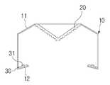
도 1은 본 발명의 바람직한 실시예에 따른 엘이디 조명장치의 분해 사시도이고, 도 2는 도 1에서 A-A 방향의 결합상태 단면 구성도이다.FIG. 1 is an exploded perspective view of an LED illumination apparatus according to a preferred embodiment of the present invention, and FIG. 2 is a cross-sectional view of an assembled state in the direction of A-A in FIG.
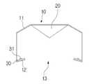
도 1과 도 2를 각각 참조하면 본 발명의 바람직한 실시예에 따른 엘이디 조명장치는, 저면에 광방출면(13)을 가지는 상자 형상이며, 내측 상부의 일부가 경사진 경사면(11)을 가지며, 광방출면(13)의 양측면 가장자리에 경사진 안착면(12)을 제공하는 케이스부(10)와, 상기 케이스부(10)의 내측 상부 중앙부에 마련된 반사부(20)와, 상기 안착면(12)에 안착되며, 다수의 엘이디(31)를 실장하는 기판(30)을 포함하여 구성된다.
Referring to FIGS. 1 and 2, the LED illumination apparatus according to the preferred embodiment of the present invention has a box-like shape having a
이하, 상기와 같이 구성되는 본 발명의 바람직한 실시예에 따른 엘이디 조명장치의 구성과 작용을 보다 상세히 설명한다.
Hereinafter, the configuration and operation of the LED illumination device according to the preferred embodiment of the present invention will be described in detail.
먼저, 케이스부(10)는 하부가 개방된 상자형의 구조를 가지고 있다. 즉, 저면에 광방출면(13)이 형성되며 그 광방출면(13)을 제외한 다른 부분은 밀폐되어, 상기 엘이디(31)의 광이 케이스부(10) 내측에서 충분히 반사될 수 있는 공간을 제공한다.
First, the
상기 케이스부(10)의 측면은 지면과 수직하며, 그 측면의 하부 끝단 일부는 케이스부(10)의 내측을 향하여 절곡되어 안착면(12)을 이룬다. 상기 안착면(12)과 상기 케이스부(10)의 측면이 이루는 내각은 90도 미만인 예각을 이룬다.A side surface of the
상기 안착면(12)은 상기 광방출면(13)에 대하여 서로 마주하는 두 변의 위치에 마련될 수 있으며, 필요에 따라서는 한 변 또는 네 변 모두에 형성될 수 있다.
The
상기 케이스부(10)의 내측 상부면의 중앙부는 평탄한 형상이며, 그 평탄한 중앙부로부터 상기 측면에 연결되는 면은 경사면(11)을 이룬다. 이 경사면(11)은 상기 케이스부(10)의 측면측으로 갈수록 낮아지는 것으로 할 수 있다.
The central portion of the inner upper surface of the
상기 케이스부(10)의 평탄한 면인 내측 상부면의 중앙부에는 반사부(20)가 위치한다. 상기 반사부(20)는 단면 형상이 역삼각형이며, 상기 케이스부(10)의 경사면(11)과 경계를 이룬다.A
즉, 상기 케이스부(10)와 반사부(20)가 이루는 공간은 상기 케이스부(10)의 경사면(11)과 반사부(20)의 경계가 이루는 부분이 가장 높은 공간이 된다.
That is, the space between the
상기 안착면(12)에는 다수의 엘이디(31)를 실장하는 기판(30)이 고정 설치된다. 따라서 상기 다수의 엘이디(31)의 광방출면은 상기 안착면(12)에 수직인 방향이 되며, 엘이디(31)에서 방출된 광은 직접 케이스부(10)의 측면 안쪽에 조사된다.
A
도 3은 본 발명의 엘이디 조명장치에서 광이 반사되는 형태를 도시한 모식도이다.3 is a schematic diagram showing a form in which light is reflected by the LED illumination device of the present invention.
도 3을 참조하면 상기 엘이디(31)의 광은 케이스부(10)의 측면측에 반사되고, 그 반사각도에 따라 케이스부(10)의 경사면(11)과 반사부(20)에서 반복적으로 반사가 이루어진다.3, the light from the
따라서 상기 엘이디(31)에서 방출된 광은 케이스부(10)의 내측공간에서 다수회의 반사가 이루어지면서, 그 케이스부(10)의 내측 공간에 가두어지는 현상이 발생한다.Accordingly, the light emitted from the
이처럼 가두어졌던 광은 상기 광방출면(13)을 통해 하향으로 방출되어, 조명을 하게 된다.
The light thus confined is emitted downward through the
상기와 같이 본 발명은 엘이디의 빛을 직접 조명에 사용하지 않고, 케이스부(10)가 이루는 공간에 광을 가두어 이를 면조명으로 제공 하기 때문에 렌즈 또는 확산판을 사용하지 않고도 눈부심이 감소하게 된다.
As described above, since the light of the LED is not directly used for the illumination, the light is confined in the space formed by the
앞서 설명한 바와 같이 확산판을 사용하지 않음으로써, 광효율을 높일 수 있으며 따라서 동일한 조도를 제공하는 기준으로 볼 때 엘이디(31)의 수량을 줄일 수 있게 되어, 보다 더 저전력의 조명장치를 제공할 수 있다.By not using the diffusion plate as described above, it is possible to increase the light efficiency, and therefore, it is possible to reduce the number of the
또한 엘이디(31)의 수를 줄임으로써 엘이디(31)에서 발생하는 열에 의한 문제점의 발생도 감소된다. 즉 별도의 방열구조를 사용하지 않고도 열의 발생에 의한 엘이디의 수명 단축을 방지할 수 있다.
Also, by reducing the number of
이처럼 방열구조를 사용하지 않아도 되는 이유의 하나로, 통상의 엘이디 조명장치는 엘이디가 천정에 설치되어, 대류에 의한 방열이 용이하지 않기 때문에 별도의 방열구조를 사용하는 방향으로 기술 개발이 이루어졌으나, 본 발명은 엘이디(31)를 천정의 외측으로 위치시킨 구조이며, 이는 대류의 용이성에 의해 열방출이 보다 더 용이하게 된다.
As one of the reasons why the heat dissipation structure is not used, a conventional LED lighting device has been developed in the direction of using a separate heat dissipation structure because the LED is installed on the ceiling and heat dissipation due to convection is not easy. The invention has a structure in which the
도 4와 도 5는 각각 본 발명의 다른 실시예에 따른 엘이디 조명장치의 단면 구성도이다.4 and 5 are cross-sectional views of an LED illumination device according to another embodiment of the present invention, respectively.
도 4와 도 5를 각각 참조하면, 반사부(20)의 형상을 상기 도 2를 참조하여 설명한 예와는 다르게 단면상 반원형(도 4)으로 하거나, 역삼각형 구조에서 반사면이 다수의 단차 또는 요철을 가지도록 형성되어, 불균일한 조도를 가지는 형태로 변형할 수 있다.4 and 5, the shape of the
도 5의 불균일한 조도를 가지는 반사면은 상기 도 4의 반사부(20) 형상에도 적용할 수 있다.
5 may be applied to the shape of the
상기 도 4의 단면상 반원형 구조의 반사부(20)와 도 5의 다수의 단차를 가지는 역삼각형 구조는 광의 반사각도를 보다 다양화하여, 상기 케이스부(10)가 이루는 공간 내에서 광의 반사와 확산이 보다 다양하고, 불규칙하게 일어나도록 할 수 있다.4 and the inverted triangular structure having a plurality of stepped portions in FIG. 5 may further diversify the reflection angle of light, and the reflection and diffusion of light in the space formed by the
이러한 다양하고 불규칙적인 광의 반사는 보다 균일한 확산이 일어나도록 하여, 상기 광방출면(13)을 통해 방출되는 광이 면광원과 보다 더 유사하게 되도록 할 수 있다.
This diverse and irregular reflection of light may cause a more uniform diffusion to cause the light emitted through the
상기 반사부(20)의 형상은 본 발명에서 모든 실시예를 도시하고 설명하기는 어려우며 엘이디(31)에서 방출되는 광을 케이스부(10)의 내측 공간에서 확산시킬 수 있는 구조이면 그 구조에 무관하게 적용될 수 있다.
The shape of the
도 6은 본 발명을 이용하여 조도를 높이는 구조의 일실시 단면 구성도이다.FIG. 6 is a configuration view of an embodiment of a structure for raising the illuminance using the present invention.
도 6을 참조하면 앞서 도 2에 도시한 구조의 본 발명을 다수로 결합하여 조도 요구치가 높은 분야에 적용할 수 있다.Referring to FIG. 6, the present invention having the structure shown in FIG.
조도 요구치가 높은 분야는 공장의 조명등이나 가로등 등 설치 높이가 상대적으로 높은 분야가 될 수 있다.
Areas with high illumination requirements can be relatively high installed areas such as factory lights and street lights.
상기 도 6의 구성은, 케이스부(10)의 측면 외측이 서로 접하도록 연결한 것으로, 조도 요구치에 부합하도록 다수의 엘이디 조명장치를 결합한 것이다. 이는 조도 요구치에 따라 케이스부(10)의 설계를 변경하는 불편함 없이, 단일한 엘이디 조명장치를 단위로 하여 동일 설계를 적용할 수 있음을 보여준다.
The configuration of FIG. 6 is such that the outside of the side surface of the
도 7은 본 발명의 다른 실시예에 따른 엘이디 조명장치의 단면 구성도이다.7 is a cross-sectional view of an LED illumination device according to another embodiment of the present invention.
도 7을 참조하면 본 발명의 다른 실시예에 따른 엘이디 조명장치는, 앞선 실시예들에서 반사부(20)를 사용하지 않고, 상기 케이스부(10)의 상부 중앙부를 상기 반사부(20)의 형상으로 절곡하여 그 케이스부(10)의 내측 상부 중앙부를 앞선 실시예들의 반사부(20)와 같이 엘이디(31)의 광을 케이스부(10) 내에서 반사 및 확산이 충분히 일어날 수 있도록 할 수 있다.7, the LED lighting apparatus according to another embodiment of the present invention may be modified such that the upper central portion of the
이러한 예는 상기 반사부(20)가 케이스부(10)와 분리된 구성품일 수 있거나, 케이스부(10)의 형상 변경으로 그 케이스부(10)와 일체인 반사부를 제공할 수 있음을 시사한다.
This example suggests that the
도 8은 본 발명의 다른 실시예에 따른 엘이디 조명장치의 단면 구성도이다.8 is a cross-sectional view of an LED illumination device according to another embodiment of the present invention.
도 8을 참조하면 본 발명은 도 7의 실시예와는 다르게 케이스부(10)의 내측 상부 중앙부가 평탄한 구조를 가지고 있다.Referring to FIG. 8, unlike the embodiment of FIG. 7, the inner upper central portion of the
이러한 구조에서는 상기 안착면(12)과 케이스부(10)의 내측 측면이 이루는 각도와 케이스부(10)의 내측 상부 가장자리인 경사면(11)의 경사에만 의존하여 엘이디(31)의 광을 케이스부(10) 내측에서 반사 및 확산시켜 면발광을 이룰 수 있다.
The light emitted from the
도 9는 본 발명의 다른 실시예에 따른 엘이디 조명장치의 단면 구성도이다.9 is a cross-sectional view of an LED illumination device according to another embodiment of the present invention.
도 9를 참조하면 본 발명은 도 7의 실시예와는 다르게 케이스부(10)와 일체인 반사부(20)를 사용하지 않고, 경사면(11)이 케이스부(10)의 상부 중앙측에서 서로 맞닿게 구성할 수 있다.9, the present invention differs from the embodiment shown in FIG. 7 in that the
이러한 구조 역시 상기 도 8의 실시예에서와 같이 안착면과 케이스부(10)의 내측 측면이 이루는 각도와 경사면(11)의 각도를 이용하여 반사 및 공간 내에서의 확산이 이루어지도록 하여, 광방출면(13)에서 면발광이 일어나도록 한다.
8, reflection and diffusion in the space are performed using the angle formed by the seating surface and the inner side surface of the
도 10은 본 발명의 바람직한 실시예에 따른 엘이디 조명장치의 설치 상태도이고, 도 11은 도 10에서 A-A 단면 구성도이고, 도 12는 도 10의 일부 측면을 도시한 동작 설명도이다.FIG. 10 is an installation view of an LED illumination apparatus according to a preferred embodiment of the present invention, FIG. 11 is a cross-sectional view taken along line A-A in FIG. 10, and FIG. 12 is an explanatory view showing an operation of a part of FIG.
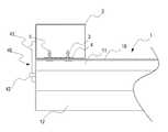
도 10 내지 도 12를 각각 참조하면 본 발명의 바람직한 실시예에 따른 엘이디 조명장치(1)는 저면에 소켓부(3)가 마련된 한 쌍의 지지프레임(2)의 양단 저면에 다수가 고정설치될 수 있다.10 to 12, the
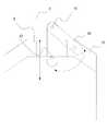
이때 각 엘이디 조명장치(1)의 교체가 용이하도록 상기 한 쌍의 지지프레임(2)의 바깥쪽 측면에는 회동축부(41)을 중심으로 회전하면서 상기 엘이디 조명장치(1)의 양단에 각각 마련된 고정돌기부(42)에 결합되어 상기 엘이디 조명장치(1)가 착탈이 용이한 상태로 고정하는 회전고정부(40)를 포함하여 구성된다.At this time, on the outer side surfaces of the pair of support frames 2, the
상기 회전고정부(40)는 판상구조이며, 상기 회동축부(41)에 의해 그 위치가 고정된 상태로 회전 가능하며, 그 회전방향으로 절개된 홈이 마련되어 상기 고정돌기부(42)가 그 절개된 홈에 삽입되도록 하여 지지프레임(2)에 엘이디 조명장치(1)를 결합 고정할 수 있다.
The
상기 엘이디 조명장치(1)의 상기 지지프레임(2)과 접하는 부분에는 돌출된 플러그(5)를 포함하며, 상기 플러그(5)는 지지프레임(2)에 마련된 소켓부(3)에 삽입되어 전원을 공급받을 수 있으며, 그 플러그(5)에는 전선이 연결되어 상기 안착면(12)에 위치하는 기판(30)에 전원을 공급한다.
The
상기 소켓부(3)는 플러그(5)가 쉽게 이탈되지 않으며, 안정적인 전원의 공급이 가능하도록 상기 플러그(5)의 측면측으로 탄성복원력을 가지는 형상으로 구성하는 것이 바람직하다.
It is preferable that the
또한 상기 도 12에 도시한 바와 같이 회전고정부(40)에 의해 본 발명에 따른 엘이디 조명장치(1)가 쉽게 탈부착 될 수 있음을 나타낸다. 회전고정부(40)에 의해 다수의 엘이디 조명장치(1)를 필요에 따라 상기 지지프레임(2)에 고정하여 사용 목적에 부합하는 조도의 조명장치를 제공할 수 있게 되며, 손상된 엘이디 조명장치(1)를 쉽게 교체하여 사용할 수 있게 된다.12 shows that the
미설명 부호 6은 상기 한 쌍의 지지프레임(2)의 상부일부를 연결하여 고정하는 고정프레임을 나타낸다. 상기 고정프레임(6)에는 천장이나 기타 위치에 고정프레임(6)을 설치할 수 있는 와이어가 제공될 수 있으며, 도면에는 생략되었으나 외부의 교류전원을 입력받아 직류전원으로 변환하여 상기 한 쌍의 지지프레임(2) 중 적어도 하나에 마련된 기판(4)을 통해 상기 소켓부(3)로 전원을 공급하는 전원공급부가 마련될 수 있다.
이와 같은 구성에 의하여 본 발명은 탈부착이 용이하게 되며, 교체가 필요한 엘이디 조명장치(1)를 하나의 단위로 교체가 가능하여, 유지 보수 및 관리 비용을 줄일 수 있는 장점이 있다.
According to this configuration, the present invention is easy to attach and detach, and it is possible to replace the
본 발명은 상기 실시예에 한정되지 않고 본 발명의 기술적 요지를 벗어나지 아니하는 범위 내에서 다양하게 수정, 변형되어 실시될 수 있음은 본 발명이 속하는 기술분야에서 통상의 지식을 가진 자에 있어서 자명한 것이다.It will be apparent to those skilled in the art that various modifications and variations can be made in the present invention without departing from the spirit and scope of the invention will be.
예를 들어 상기 케이스부(10)의 내면 전체는 광반사효율을 높이기 위하여 반사면으로 처리되거나, 반사시트가 부착된 것일 수 있다.
For example, the entire inner surface of the
10:케이스부 11:경사면
12:안착면 13:광방출면
20:반사부 30:기판
31:엘이디10: case part 11: inclined surface
12: seat surface 13: light emitting surface
20: reflection part 30: substrate
31: LED
Claims (11)
Translated fromKorean상기 케이스부의 측면부가 케이스의 내측으로 절곡된 안착면과,
상기 안착면 상에 고정되며, 다수의 엘이디가 실장되는 기판을 포함하는 엘이디 조명장치.
A case portion having a predetermined depth and enclosing a remaining portion except for the light emitting surface so as to provide a reflective space,
A side surface portion of the case portion being folded toward the inside of the case,
And a substrate fixed on the seating surface and having a plurality of LEDs mounted thereon.
상기 안착면은,
상기 케이스부의 측면부 내측과의 내각이 예각인 것을 특징으로 하는 엘이디 조명장치.
The method according to claim 1,
The seat surface
And an inner angle of the inside of the side portion of the case portion is an acute angle.
상기 케이스부의 내측 상부 중앙부에 위치하여 상기 엘이디의 광을 반사시켜, 상기 케이스부가 제공하는 상기 반사공간 내에서 광의 반사 및 확산이 이루어지도록 하는 반사부를 포함하는 엘이디 조명장치.
The method according to claim 1,
And a reflector positioned at an inner upper central portion of the case portion and reflecting the light of the LED to cause reflection and diffusion of light in the reflective space provided by the case portion.
상기 반사부는 상기 케이스부의 상부 중앙부가 하향 절곡된 것을 특징으로 하는 엘이디 조명장치.
The method of claim 3,
Wherein the reflective portion is bent downward at an upper center portion of the case portion.
상기 케이스부의 내측 상부의 상기 경사면은,
상기 반사부에서 상기 케이스부의 측면까지 위치하며, 상기 케이스부의 측면측이 낮도록 경사진 것을 특징으로 하는 엘이디 조명장치.
The method according to claim 3 or 4,
The inclined surface on the inner upper side of the case portion
And the side of the case part is lower than the side of the case part.
상기 케이스부 내측 상부의 상기 경사면은,
상기 케이스부의 내측 상부 중앙에서 서로 접하며, 상기 케이스부의 측면까지 위치하며, 상기 케이스부의 측면측이 낮도록 경사진 것을 특징으로 하는 엘이디 조명장치.
The method according to claim 1,
The inclined surface on the inside upper side of the case part
Wherein the upper surface of the case part is in contact with the inner upper center of the case part, and the side surface of the case part is lower than the side surface of the case part.
상기 반사부는,
단면이 역삼각형 또는 반원형인 것을 특징으로 하는 엘이디 조명장치.
The method according to claim 3 or 4,
The reflector includes:
Wherein the cross section is inverted triangular or semicircular.
상기 반사부는 단차 또는 요철을 가지는 반사면을 제공하는 것을 특징으로 하는 엘이디 조명장치.
8. The method of claim 7,
Wherein the reflective portion provides a reflecting surface having a step or protrusion.
상기 케이스부의 상부 양단부가 다수로 결합 되는 한 쌍의 지지프레임을 더 포함하되,
상기 케이스부의 탈부착이 용이하도록 상기 한 쌍의 지지프레임의 바깥쪽에는 회전결합부가 마련된 것을 특징으로 하는 엘이디 조명장치.
The method according to claim 1,
And a pair of support frames to which both ends of the upper portion of the case are coupled in plural,
Wherein a rotation engaging portion is provided on an outer side of the pair of support frames to facilitate detachment and attachment of the case portion.
상기 회전결합부는,
상기 지지프레임의 측면에 마련된 회동축부에 위치가 고정된 상태로 회전가능하며, 상기 케이스부의 양단부에 마련된 고정돌기부가 끼움결합되는 절개홈이 마련된 것을 특징으로 하는 엘이디 조명장치.
10. The method of claim 9,
The rotary coupling unit includes:
Wherein the case is provided with a cutout groove in which a fixing protrusion provided at both ends of the case portion is fitted and fitted into a rotatable shaft portion provided on a side surface of the support frame.
상기 지지프레임은 전원의 공급을 위한 소켓부가 마련되어 있으며,
상기 지지프레임의 상부에는 상기 기판에 연결되는 플러그가 돌출되어, 상기 지지프레임과 상기 케이스부의 결합에 의해 상기 기판에 전원이 공급되는 것을 특징으로 하는 엘이디 조명장치.
11. The method according to claim 9 or 10,
The support frame is provided with a socket for supplying power,
Wherein a plug connected to the substrate protrudes from the upper portion of the support frame, and power is supplied to the substrate by the engagement of the support frame and the case portion.
Priority Applications (6)
| Application Number | Priority Date | Filing Date | Title |
|---|---|---|---|
| PCT/KR2013/009629WO2014069857A1 (en) | 2012-10-30 | 2013-10-28 | Led lighting apparatus |
| EP13850576.3AEP2916063B1 (en) | 2012-10-30 | 2013-10-28 | Led lighting apparatus |
| AU2013338872AAU2013338872B2 (en) | 2012-10-30 | 2013-10-28 | LED lighting apparatus |
| JP2015540597AJP6379098B2 (en) | 2012-10-30 | 2013-10-28 | LED lighting device |
| US14/699,317US9810399B2 (en) | 2012-10-30 | 2015-04-29 | LED lighting apparatus |
| JP2017048444AJP2017103259A (en) | 2012-10-30 | 2017-03-14 | LED lighting device |
Applications Claiming Priority (2)
| Application Number | Priority Date | Filing Date | Title |
|---|---|---|---|
| KR1020120121277 | 2012-10-30 | ||
| KR20120121277 | 2012-10-30 |
Publications (1)
| Publication Number | Publication Date |
|---|---|
| KR20140055943Atrue KR20140055943A (en) | 2014-05-09 |
Family
ID=50887485
Family Applications (1)
| Application Number | Title | Priority Date | Filing Date |
|---|---|---|---|
| KR1020130073097ACeasedKR20140055943A (en) | 2012-10-30 | 2013-06-25 | Led lighting device |
Country Status (6)
| Country | Link |
|---|---|
| US (1) | US9810399B2 (en) |
| EP (1) | EP2916063B1 (en) |
| JP (2) | JP6379098B2 (en) |
| KR (1) | KR20140055943A (en) |
| AU (1) | AU2013338872B2 (en) |
| WO (1) | WO2014069857A1 (en) |
Cited By (1)
| Publication number | Priority date | Publication date | Assignee | Title |
|---|---|---|---|---|
| CN104154446A (en)* | 2014-08-07 | 2014-11-19 | 张勇 | Novel reflection-type LED fluorescent tube |
Families Citing this family (13)
| Publication number | Priority date | Publication date | Assignee | Title |
|---|---|---|---|---|
| KR20140055943A (en)* | 2012-10-30 | 2014-05-09 | 주식회사 케이엠더블유 | Led lighting device |
| JP6226183B2 (en)* | 2013-11-05 | 2017-11-08 | レシップホールディングス株式会社 | lighting equipment |
| CN105874271B (en)* | 2013-11-18 | 2019-07-09 | 飞利浦灯具控股公司 | Acoustics lighting tiles |
| DE202014103605U1 (en)* | 2014-08-04 | 2014-08-21 | Brillant Ag | Electric light |
| KR101601531B1 (en)* | 2014-11-07 | 2016-03-10 | 주식회사 지엘비젼 | Lighting Device |
| ITUA20161504A1 (en)* | 2016-03-09 | 2017-09-09 | Neri S P A | OPTIC AND ILLUMINATING BODY |
| EP3631287B1 (en) | 2017-05-25 | 2021-07-07 | Signify Holding B.V. | Luminaire |
| US10670205B2 (en)* | 2018-03-09 | 2020-06-02 | Finelite Inc. | Open channel LED light fixture for indirect lighting |
| US10718476B2 (en)* | 2018-03-09 | 2020-07-21 | Finelite Inc. | LED light fixture for indirect lighting with adaptable baffle structure |
| NL2022161B1 (en)* | 2018-12-10 | 2020-07-02 | Veko Lightsystems Int B V | LED-equipped light fixture for high light output |
| JP7125813B2 (en)* | 2019-06-03 | 2022-08-25 | 株式会社モデュレックス | Luminaire body |
| US10928020B1 (en)* | 2019-08-22 | 2021-02-23 | Usg Interiors, Llc | Light bar for suspended ceiling |
| JP7399678B2 (en)* | 2019-10-28 | 2023-12-18 | 株式会社ダイセル | Resin molding for optical semiconductor devices and optical semiconductor devices |
Family Cites Families (25)
| Publication number | Priority date | Publication date | Assignee | Title |
|---|---|---|---|---|
| US2721635A (en)* | 1953-02-16 | 1955-10-25 | Fullerton Mfg Corp | Door assembly |
| JPH06131905A (en)* | 1992-10-14 | 1994-05-13 | Tokyo Electric Co Ltd | lighting equipment |
| JPH11134913A (en)* | 1997-10-31 | 1999-05-21 | Toshiba Lighting & Technology Corp | lighting equipment |
| US6149283A (en)* | 1998-12-09 | 2000-11-21 | Rensselaer Polytechnic Institute (Rpi) | LED lamp with reflector and multicolor adjuster |
| JP4527230B2 (en)* | 2000-02-28 | 2010-08-18 | 三菱電機照明株式会社 | Surface-emitting LED light source |
| JP2003036722A (en)* | 2001-07-25 | 2003-02-07 | Toshiba Lighting & Technology Corp | lighting equipment |
| US7635198B2 (en)* | 2004-06-18 | 2009-12-22 | Acuity Brands, Inc. | Replacement light fixture and lens assembly for same |
| US7255459B2 (en)* | 2005-12-16 | 2007-08-14 | United Microdisplay Optronics Corp. | Light emitting diode light source |
| US7658506B2 (en)* | 2006-05-12 | 2010-02-09 | Philips Solid-State Lighting Solutions, Inc. | Recessed cove lighting apparatus for architectural surfaces |
| US20080030982A1 (en)* | 2006-08-04 | 2008-02-07 | Vode Llc | Modular lighting system |
| US8374498B2 (en)* | 2006-09-29 | 2013-02-12 | Microscan Systems, Inc. | Systems and/or devices for camera-based inspections |
| JP5030661B2 (en)* | 2007-05-16 | 2012-09-19 | シャープ株式会社 | Lighting device |
| CN101681059B (en)* | 2007-05-29 | 2014-03-05 | 皇家飞利浦电子股份有限公司 | Lighting systems, illuminators and backlight units |
| CN104197247A (en)* | 2007-12-18 | 2014-12-10 | 皇家飞利浦电子股份有限公司 | Illumination system, luminaire and backlighting unit |
| JP2010033893A (en)* | 2008-07-29 | 2010-02-12 | Nec Lighting Ltd | Light-emitting device and light emission method |
| KR100998980B1 (en) | 2008-09-12 | 2010-12-09 | 자화전자(주) | LED lighting device with direct placement without border |
| US8579473B2 (en)* | 2008-09-12 | 2013-11-12 | Koninklijke Philips N.V. | Luminaire for indirect illumination |
| KR20100103327A (en)* | 2009-03-13 | 2010-09-27 | 이엔지테크놀러지 주식회사 | Fluorescent lamp unit |
| US8000594B2 (en)* | 2009-07-02 | 2011-08-16 | Microscan Systems, Inc. | Diffuse reflective illuminator |
| KR101114159B1 (en)* | 2009-07-23 | 2012-03-09 | 엘지이노텍 주식회사 | Lgiht emitting device |
| US8197105B2 (en)* | 2009-08-13 | 2012-06-12 | Intematix Corporation | LED-based lamps |
| JP5421711B2 (en)* | 2009-09-30 | 2014-02-19 | イーデーエム株式会社 | Lighting device |
| KR101652816B1 (en)* | 2010-04-10 | 2016-09-01 | 엘지이노텍 주식회사 | Lighting device |
| JP2012204146A (en)* | 2011-03-25 | 2012-10-22 | Toshiba Lighting & Technology Corp | Led lighting fixture |
| KR20140055943A (en)* | 2012-10-30 | 2014-05-09 | 주식회사 케이엠더블유 | Led lighting device |
- 2013
- 2013-06-25KRKR1020130073097Apatent/KR20140055943A/ennot_activeCeased
- 2013-10-28AUAU2013338872Apatent/AU2013338872B2/ennot_activeCeased
- 2013-10-28EPEP13850576.3Apatent/EP2916063B1/ennot_activeNot-in-force
- 2013-10-28JPJP2015540597Apatent/JP6379098B2/ennot_activeExpired - Fee Related
- 2013-10-28WOPCT/KR2013/009629patent/WO2014069857A1/enactiveApplication Filing
- 2015
- 2015-04-29USUS14/699,317patent/US9810399B2/enactiveActive
- 2017
- 2017-03-14JPJP2017048444Apatent/JP2017103259A/enactivePending
Cited By (1)
| Publication number | Priority date | Publication date | Assignee | Title |
|---|---|---|---|---|
| CN104154446A (en)* | 2014-08-07 | 2014-11-19 | 张勇 | Novel reflection-type LED fluorescent tube |
Also Published As
| Publication number | Publication date |
|---|---|
| JP6379098B2 (en) | 2018-08-22 |
| US20150241023A1 (en) | 2015-08-27 |
| EP2916063A1 (en) | 2015-09-09 |
| EP2916063A4 (en) | 2016-06-08 |
| US9810399B2 (en) | 2017-11-07 |
| JP2017103259A (en) | 2017-06-08 |
| EP2916063B1 (en) | 2017-09-20 |
| WO2014069857A1 (en) | 2014-05-08 |
| AU2013338872B2 (en) | 2016-12-22 |
| JP2015537348A (en) | 2015-12-24 |
| AU2013338872A1 (en) | 2015-06-11 |
Similar Documents
| Publication | Publication Date | Title |
|---|---|---|
| KR20140055943A (en) | Led lighting device | |
| EP2752617B1 (en) | Spherical lamp with easy heat dissipation | |
| KR20200002186A (en) | Line type led lighting apparatus | |
| US10060608B2 (en) | Detachable LED lighting device | |
| KR20160000972A (en) | An indirect lighting device using LED | |
| KR101568669B1 (en) | LED lighting device | |
| JP4676563B1 (en) | LED lighting device integrated with lighting equipment. | |
| KR20110050060A (en) | Linear LED Lamps for Fluorescent Lamps | |
| KR101023826B1 (en) | Bulb type LED lamp | |
| KR200471915Y1 (en) | Lighting Apparautus. | |
| KR101325080B1 (en) | A led candle lamp | |
| CN209801280U (en) | Anti-dazzle spotlight | |
| KR20110000897A (en) | LED lighting | |
| KR200485494Y1 (en) | LED PL Lighting Device | |
| KR20160126385A (en) | Anti-glare LED lighting device | |
| KR20160071501A (en) | LED lighting module for medical treatment | |
| KR100985275B1 (en) | Modular LED Lamps | |
| CN216643877U (en) | Anti-dazzle lamp | |
| JP2012099456A (en) | Lighting device | |
| KR200448152Y1 (en) | Lighting device for embedding light emitting diode | |
| KR101020637B1 (en) | Led lighting fixtures | |
| KR101741152B1 (en) | Detachable type LED lighting device | |
| KR20200124124A (en) | Embedded LED Lighting System | |
| KR101181340B1 (en) | LED light | |
| KR101260289B1 (en) | LED Lighting apparatus |
Legal Events
| Date | Code | Title | Description |
|---|---|---|---|
| PA0109 | Patent application | Patent event code:PA01091R01D Comment text:Patent Application Patent event date:20130625 | |
| PG1501 | Laying open of application | ||
| PN2301 | Change of applicant | Patent event date:20171027 Comment text:Notification of Change of Applicant Patent event code:PN23011R01D | |
| PN2301 | Change of applicant | Patent event date:20180412 Comment text:Notification of Change of Applicant Patent event code:PN23011R01D | |
| PA0201 | Request for examination | Patent event code:PA02012R01D Patent event date:20180622 Comment text:Request for Examination of Application Patent event code:PA02011R01I Patent event date:20130625 Comment text:Patent Application | |
| E902 | Notification of reason for refusal | ||
| PE0902 | Notice of grounds for rejection | Comment text:Notification of reason for refusal Patent event date:20190620 Patent event code:PE09021S01D | |
| E601 | Decision to refuse application | ||
| PE0601 | Decision on rejection of patent | Patent event date:20191130 Comment text:Decision to Refuse Application Patent event code:PE06012S01D Patent event date:20190620 Comment text:Notification of reason for refusal Patent event code:PE06011S01I |