KR20140047412A - Tandem array lens sheet - Google Patents
Tandem array lens sheetDownload PDFInfo
- Publication number
- KR20140047412A KR20140047412AKR1020120113681AKR20120113681AKR20140047412AKR 20140047412 AKR20140047412 AKR 20140047412AKR 1020120113681 AKR1020120113681 AKR 1020120113681AKR 20120113681 AKR20120113681 AKR 20120113681AKR 20140047412 AKR20140047412 AKR 20140047412A
- Authority
- KR
- South Korea
- Prior art keywords
- lens sheet
- sheet
- lens
- microlenses
- fine
- Prior art date
- Legal status (The legal status is an assumption and is not a legal conclusion. Google has not performed a legal analysis and makes no representation as to the accuracy of the status listed.)
- Withdrawn
Links
Images


Classifications
- G—PHYSICS
- G02—OPTICS
- G02B—OPTICAL ELEMENTS, SYSTEMS OR APPARATUS
- G02B5/00—Optical elements other than lenses
- G02B5/02—Diffusing elements; Afocal elements
- G02B5/0205—Diffusing elements; Afocal elements characterised by the diffusing properties
- G02B5/0257—Diffusing elements; Afocal elements characterised by the diffusing properties creating an anisotropic diffusion characteristic, i.e. distributing output differently in two perpendicular axes
- G—PHYSICS
- G02—OPTICS
- G02B—OPTICAL ELEMENTS, SYSTEMS OR APPARATUS
- G02B5/00—Optical elements other than lenses
- G02B5/02—Diffusing elements; Afocal elements
- G02B5/0205—Diffusing elements; Afocal elements characterised by the diffusing properties
- G02B5/021—Diffusing elements; Afocal elements characterised by the diffusing properties the diffusion taking place at the element's surface, e.g. by means of surface roughening or microprismatic structures
- G02B5/0221—Diffusing elements; Afocal elements characterised by the diffusing properties the diffusion taking place at the element's surface, e.g. by means of surface roughening or microprismatic structures the surface having an irregular structure
- G—PHYSICS
- G02—OPTICS
- G02B—OPTICAL ELEMENTS, SYSTEMS OR APPARATUS
- G02B5/00—Optical elements other than lenses
- G02B5/02—Diffusing elements; Afocal elements
- G02B5/0205—Diffusing elements; Afocal elements characterised by the diffusing properties
- G02B5/021—Diffusing elements; Afocal elements characterised by the diffusing properties the diffusion taking place at the element's surface, e.g. by means of surface roughening or microprismatic structures
- G02B5/0231—Diffusing elements; Afocal elements characterised by the diffusing properties the diffusion taking place at the element's surface, e.g. by means of surface roughening or microprismatic structures the surface having microprismatic or micropyramidal shape
Landscapes
- Physics & Mathematics (AREA)
- General Physics & Mathematics (AREA)
- Optics & Photonics (AREA)
- Planar Illumination Modules (AREA)
- Liquid Crystal (AREA)
- Optical Elements Other Than Lenses (AREA)
Abstract
Translated fromKoreanDescription
Translated fromKorean본 발명은 액정표시장치(LCD)에 사용되는 백라이트 유닛(BLU)의 광학 성능을 향상시키기 위한 렌즈가 탠덤 형식으로 배열(tandem array)된 광학시트에 관한 것이다.The present invention relates to an optical sheet having a tandem array of lenses for improving optical performance of a backlight unit (BLU) used in a liquid crystal display (LCD).
액정표시장치는 정보사회 환경 및 기술의 발전에 따라 그 응용범위가 점차 확대되고 있으며, 액정표시장치로서 많은 모델의 제품이 출시되고 있다. 이와 같은 액정표시장치의 패널은 스스로 발광하지 못하므로 패널 뒤에서 광을 제공해 주는 백라이트 유닛을 구비해야 한다.The liquid crystal display device is gradually expanding its application range according to the information society environment and the development of technology, and many models of the liquid crystal display device have been released. Since the panel of such a liquid crystal display device does not emit light by itself, it should be provided with a backlight unit that provides light behind the panel.
백라이트 유닛은 LED 또는 램프와 같은 광원과, 광원에서 나오는 빛을 화면에 고루 퍼지게 하는 도광판, 그리고 반사 필름, 확산 필름, 집광 필름, 편광 필름 등 각종 광학 필름들로 구성된다. 이런 백라이트 유닛은 광원의 조광 방향에 따라 엣지형과 직하형으로 구분된다.The backlight unit includes a light source such as an LED or a lamp, a light guide plate that spreads light emitted from the light source evenly on a screen, and various optical films such as a reflective film, a diffusion film, a light collecting film, and a polarizing film. Such a backlight unit is classified into an edge type and a direct type according to the dimming direction of the light source.
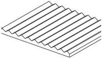
집광 필름은 빛을 굴절 혹은 반사시켜 주는 패턴이 삽입된 형태로, 일반적으로 마이크로 렌즈 시트(도 1 참조)와 프리즘 시트(도 2 참조)가 주로 사용된다. 그러나, 프리즘 시트는 광특성은 우수하나 은폐력(shielding property)이 부족한 문제가 있고, 마이크로 렌즈 시트는 은폐력은 우수하나 광특성이 낮은 문제가 있다.The light condensing film is a form in which a pattern for refracting or reflecting light is inserted. Generally, a micro lens sheet (see FIG. 1) and a prism sheet (see FIG. 2) are mainly used. However, the prism sheet has a problem of excellent optical properties but lack of shielding properties, and the microlens sheet has a problem of excellent hiding power but low optical properties.
이런 이유로, 기능상 프리즘 시트와 마이크로 렌즈 시트의 중간에 위치하는 은폐력이 우수하면서 광특성도 우수한 또 다른 패턴 집광 필름의 필요성이 대두되고 있다. 일례로, 대한민국 공개특허공보 제 2010-4537 호는 광 확산층의 일면에 프리즘 배열이 형성된 시트로서 프리즘 꼭지부에 소정의 곡률을 갖는 두 개 이상의 반구 형상의 광학 구조물이 동일한 결 방향으로 형성되어 있는 복합 광학시트를 개시하고 있다.For this reason, there is a need for another pattern condensing film that has excellent hiding power and excellent optical properties positioned between the functional prism sheet and the micro lens sheet. For example, Korean Patent Laid-Open Publication No. 2010-4537 is a composite sheet in which a prism array is formed on one surface of a light diffusion layer, in which two or more hemispherical optical structures having a predetermined curvature in a prism vertex are formed in the same grain direction. An optical sheet is disclosed.
따라서, 본 발명의 목적은 종래의 광학시트의 단점을 보완하는, 은폐력과 광특성이 모두 우수한 새로운 패턴의 광학시트를 제공하는 것이다.Accordingly, it is an object of the present invention to provide a new pattern of optical sheet excellent in both hiding power and optical properties, which compensates for the disadvantages of the conventional optical sheet.
상기 목적에 따라, 본 발명은한쪽 또는 양쪽 표면 상에 형성된 복수의 볼록형 미세 렌즈를 포함하는 시트로서, 상기 미세 렌즈가 열(row)에 맞추어 인접한 복수의 열로 배열(tandem array)되되 같은 열 내에서 서로 이웃하는 미세 렌즈끼리 부분적으로 중첩되어 연결된 것을 특징으로 하는, 렌즈 시트를 제공한다.In accordance with the above object, the present invention A sheet comprising a plurality of convex microlenses formed on one or both surfaces, wherein the microlenses are arranged in a plurality of adjacent rows in accordance with a row, and partially adjacent to each other in the same row. Provided is a lens sheet, which is connected in an overlapping manner.
본 발명에 따른 렌즈 시트는 탠덤 배열 방식의 렌즈로 인해 은폐력과 광특성이 모두 우수하고, 주름, 모아레, 웨트아웃(wet-out) 현상 등을 방지할 수 있으므로, 액정표시장치에 사용되는 백라이트 유닛의 광학시트로서 유용하게 활용될 수 있다.
The lens sheet according to the present invention has excellent hiding power and optical characteristics due to the tandem array lens, and can prevent wrinkles, moiré, and wet-out phenomenon, and therefore, the backlight unit used in the liquid crystal display device. It can be usefully used as an optical sheet of.
도 1 및 2 는 기존의 마이크로 렌즈 시트 및 프리즘 시트를 각각 나타낸 것이다.
도 3 내지 6 은 본 발명의 렌즈 시트의 일례를 나타낸 모식도로서, 구체적으로, 도 3 은 3 차원적으로 나타낸 것이고, 도 4 는 평면적으로 나타낸 것이며, 도 5 및 6 은 열 방향(도 4 의 y-y' 방향)에 대한 단면을 나타낸 것이다.
도 7 은 본 발명의 렌즈 시트에서 개별 미세 렌즈의 단면 형상을 예시한 것이다.
도 8 은 백라이트 유닛에서 본 발명의 렌즈 시트(a)와 기존의 마이크로 렌즈 시트(b)의 광도 시야각을 측정한 것이다.
도 9 는 백라이트 유닛에서 본 발명의 렌즈 시트(a)와 기존의 마이크로 렌즈 시트(b)의 광특성 및 은폐력을 비교한 것이다.
도 10 은 백라이트 유닛에서 교차 프리즘 시트에 있어서 광원 쪽의 프리즘 시트로서, 각각 본 발명의 렌즈 시트(a), 기존의 마이크로 렌즈 시트(b), 및 기존의 프리즘 시트(c)를 형성했을 경우의 수평 시야각을 측정한 것이다.
1 and 2 show a conventional micro lens sheet and a prism sheet, respectively.
3 to 6 are schematic views showing an example of the lens sheet of the present invention. Specifically, FIG. 3 is shown in three dimensions, FIG. 4 is shown in plan, and FIGS. 5 and 6 are in the column direction (yy in FIG. 4). 'Cross-section).
7 illustrates the cross-sectional shape of individual micro lenses in the lens sheet of the present invention.
8 is a view of measuring the luminance viewing angle of the lens sheet (a) of the present invention and the conventional micro lens sheet (b) in the backlight unit.
9 is a comparison of the optical characteristics and hiding power of the lens sheet (a) of the present invention and the conventional micro lens sheet (b) in the backlight unit.
Fig. 10 shows the prism sheet on the light source side in the cross prism sheet in the backlight unit, in which the lens sheet (a) of the present invention, the conventional micro lens sheet (b), and the conventional prism sheet (c) are formed, respectively. The horizontal viewing angle is measured.
본 발명의 렌즈 시트는 한쪽 또는 양쪽 표면 상에 형성된 복수의 볼록형 미세 렌즈를 포함하는 시트로서, 이하 첨부한 도면을 참조하여 본 발명의 렌즈 시트를 보다 구체적으로 설명한다.
The lens sheet of the present invention is a sheet including a plurality of convex microlenses formed on one or both surfaces, which will be described below in detail with reference to the accompanying drawings.
미세 렌즈의 배열 패턴Array Pattern of Fine Lenses
본 발명의 렌즈 시트 표면 상에 형성된 미세 렌즈는, 도 3 내지 6 에서 보는 바와 같이, 열(도 4의 y-y'방향)에 맞추어 인접한 복수의 열로 배열되며, 같은 열 내에서 서로 이웃하는 렌즈끼리 부분적으로 중첩되어 연결된 형태를 갖는다.The microlenses formed on the surface of the lens sheet of the present invention, as shown in Figs. 3 to 6, are arranged in a plurality of rows adjacent to each other in a row (y-y 'direction in Fig. 4) and adjacent to each other in the same row. The parts overlap each other and have a connected form.
즉, 본 발명의 렌즈 시트는, 종래의 마이크로 렌즈 시트처럼 단일 렌즈들이 독립적으로 배열된 형태(도 1 참조) 또는 종래의 프리즘 시트처럼 한쪽 방향으로 길게 늘어뜨린 렌즈들이 수직된 방향으로 배열된 형태(도 2 참조)와는 달리, 단일 렌즈들이 탠덤 형식으로 배열되면서 개개의 열 내에서 일부 중첩되어 연결되어 있는 것을 특징으로 한다.That is, the lens sheet of the present invention has a form in which single lenses are arranged independently like a conventional micro lens sheet (see FIG. 1) or lenses in which a long line of lenses is arranged in a vertical direction such as a conventional prism sheet ( Unlike FIG. 2, single lenses are arranged in tandem and are partially overlapped and connected in individual rows.
보다 구체적으로 본 발명의 렌즈 시트는, 서로 분리되어 규칙적으로 배열된 개별적인 반구형 렌즈를 포함하는 기존의 마이크로 렌즈 시트와는 달리, 일부가 중첩 연결되어 탠덤 배열된 미세 렌즈를 포함함으로써 휘도와 같은 광특성을 향상시킬 수 있다. 또한, 기존의 프리즘 시트가 한쪽 방향(즉 결 방향)으로 규칙성 있는 연속적인 렌즈가 형성된 것과는 달리, 본 발명의 렌즈 시트는 개개의 열 내에서 일부분만 랜덤(random)하게 중첩된 연결 부위를 가지므로, 빛의 경로를 변화시켜 렌즈 배열 패턴을 은폐시키는 효과를 향상시키고 고온 또는 다습 등의 환경에서도 레진의 영향도를 저하시켜 기존 UV 경화 제품들의 취약점인 주름 현상을 방지하는 효과가 있다.
More specifically, the lens sheet of the present invention, unlike the conventional micro lens sheet including the individual hemispherical lens arranged separately from each other, and includes a microlens in which part is overlapped and tandem arranged, optical properties such as luminance Can improve. In addition, unlike conventional prism sheets in which regular lenses are formed in one direction (i.e. grain direction), the lens sheet of the present invention has connecting portions randomly overlapping only a portion within individual rows. Therefore, by changing the path of the light to improve the effect of hiding the lens array pattern, the effect of the resin is reduced in the environment, such as high temperature or high humidity, it is effective to prevent the wrinkles vulnerabilities of existing UV curing products.
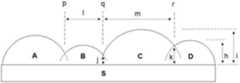
또한, 도 5 에서 예시되는 바와 같이, 상기 개개의 열 내에서 일렬로 배열된 미세 렌즈들(A, B, C, D)은 서로 중첩된 지점(p, q, r) 간의 거리(l, m)가 예를 들어 10 내지 3,000 ㎛ 범위일 수 있고, 또는 휘도 등을 고려하여 50 내지 3,000 ㎛ 범위일 수 있으며, 더 구체적으로는 300 내지 700 ㎛ 범위일 수 있고, 특히 상기 범위 내에서 랜덤하게 변화할 수 있다. 이와 같이, 중첩 연결되는 부분이 랜덤하게 형성됨으로써 모아레(moire) 등의 현상을 방지할 수 있다.In addition, as illustrated in FIG. 5, the fine lenses A, B, C, and D arranged in a row in the respective columns have a distance l, m between the overlapping points p, q, and r. ) May be, for example, in the range of 10 to 3,000 μm, or may be in the range of 50 to 3,000 μm in consideration of luminance, etc., more specifically in the range of 300 to 700 μm, and particularly randomly changed within the above range. can do. As such, the overlapped portions are randomly formed, thereby preventing a phenomenon such as moire.
아울러, 미세 렌즈 간에 중첩되는 정도도 랜덤하게 나타나는데, 도 5 의 미세 렌즈(C)를 예로 들면, 이웃 렌즈(B, D)와의 중첩 지점(q, r)의 기재층(S)으로부터의 높이(j, k)는 서로 다를 수 있으며, 상기 중첩 지점의 높이(j, k)는 예를 들어 0㎛ 초과 300㎛ 미만의 범위 내에서 랜덤할 수 있고, 또는 0㎛ 초과 50㎛ 미만의 범위 내에서 랜덤할 수 있다.In addition, the degree of overlap between the microlenses is also randomly displayed. For example, when the microlenses C of FIG. 5 are used, the height (from the base layer S of the overlapping points q and r with the neighboring lenses B and D) is determined. j, k) may be different from each other, and the heights j, k of the overlapping points may be random, for example, in a range of more than 0 μm and less than 300 μm, or in a range of more than 0 μm and less than 50 μm. It can be random.
개개의 미세 렌즈는 같은 열 내에서 서로 다른 높이(h, i)를 가질 수 있으며, 이와 같이 미세 렌즈들이 서로 다른 높이로 형성되어 웨트아웃 현상을 방지할 수 있다. 미세 렌즈의 최저 높이에 대한 최고 높이의 비율이 예를 들어 1 초과 3 이하일 수 있으며, 또는 1 초과 1.5 이하일 수 있다. 또한, 미세 렌즈의 최대 높이는 예를 들어 1 내지 300 ㎛일 수 있으며, 또는 1 내지 50 ㎛일 수 있다.The individual microlenses may have different heights h and i in the same row, and thus the microlenses may be formed at different heights to prevent the wetout phenomenon. The ratio of the highest height to the lowest height of the microlenses may be for example greater than 1 and less than or equal to 3, or greater than or equal to 1.5 and less than or equal to 1. In addition, the maximum height of the microlenses may be, for example, 1 to 300 μm, or may be 1 to 50 μm.
또한, 도 6 에서 예시되는 바와 같이, 상기 개개의 열 내에서 서로 이웃하는 두 개의 미세 렌즈(B, C)가 중첩된 지점(q)에서 상기 두 미세 렌즈(B, C)의 표면에 대한 각각의 접선(q-b, q-c) 사이의 각도(a)가 1°내지 150°의 범위일 수 있다.
Further, as illustrated in FIG. 6, each of the surfaces of the two micro lenses B and C at the point q at which the two micro lenses B and C neighboring each other in the respective rows overlap. The angle a between the tangents qb and qc may be in the range of 1 ° to 150 °.
개별 미세 렌즈의 형상은 위에서 보았을 때에는 도 4 에서와 같이 열 방향(y-y')으로 대체로 길쭉한 형태일 수 있으며, 예를 들어, 본 발명의 렌즈 시트를 위에서 보았을 때, 미세 렌즈가 일렬로 배열된 열(y-y')의 폭(w)은 예를 들어 10 내지 200 ㎛ 범위일 수 있고 보다 바람직하게는 30 내지 100 ㎛ 범위일 수 있으며, 또한 랜덤하게 중첩된 지점 간의 거리(d)는 예를 들어 10 내지 3,000 ㎛ 범위일 수 있고 보다 바람직하게는 50 내지 3,000 ㎛ 범위일 수 있다. 개별적인 미세 렌즈를 기준으로 설명하면, 개별 미세 렌즈의 크기는 열의 폭 방향으로는 10 내지 200 ㎛일 수 있고, 열의 길이 방향으로는 10 내지 3,000 ㎛ 일 수 있다.
The shape of the individual microlenses may be generally elongated in the column direction (y-y ') as seen from above when viewed from above. For example, when viewed from above, the microlenses are arranged in a row. The width w of the given rows y-y 'may for example be in the range of 10 to 200 μm and more preferably in the range of 30 to 100 μm and also the distance d between the randomly overlapping points For example, it may range from 10 to 3,000 μm, more preferably from 50 to 3,000 μm. Referring to the individual fine lenses, the size of the individual fine lenses may be 10 to 200 μm in the width direction of the column, and may be 10 to 3,000 μm in the length direction of the column.
또한, 배열된 개개의 미세 렌즈는 도 7에서 보듯이 매우 다양한 단면 형상을 가질 수 있다.In addition, the individual fine lenses arranged may have a wide variety of cross-sectional shapes as shown in FIG.
예를 들어, 열에 수직한 방향(도 4의 x-x'방향)의 단면 형상을 관찰하였을 때, 반원형(i), 반타원형(ii), 포물선형(iii), 쌍곡선형(iv), 모서리가 뾰족한 삼각형(v), 또는 모서리가 둥근 삼각형(vi)의 단면 형상을 가질 수 있으며, 바람직하게는, 렌즈의 단면으로서 반타원형 혹은 포물선형 등의 비구면 형상이 적용될 경우 은폐력을 향상시키고 반치각 등의 시야각 특성을 향상시킬 수 있다.For example, when the cross-sectional shape in the direction perpendicular to the column (x-x 'direction in Fig. 4) is observed, the semicircle (i), the semi-ellipse (ii), the parabolic (iii), the hyperbolic (iv), and the corners are observed. It may have a cross-sectional shape of a sharp triangle (v) or a rounded triangle (vi). Preferably, when an aspherical shape such as a semi-elliptic or parabolic shape is applied as a cross section of the lens, the concealing force may be improved and the half-angle angle may be used. Can improve the viewing angle characteristics.
또한, 열 방향(도 4의 y-y'방향)의 단면 형상을 관찰하였을 때, 중첩되는 부분을 고려하지 않은 개개의 미세 렌즈는, 모서리가 둥근 사다리꼴 또는 반타원형의 단면 형상으로서, 예를 들어, 렌즈 중간부 평면부가 긴 형상(vii), 렌즈 중간부 평면부가 짧은 형상(viii), 또는 렌즈 중간부 평면부가 없는 형상(ix)의 단면을 가질 수 있다. 이 때, 미세 렌즈끼리의 중첩은 상기 단면 형상에서 렌즈 좌우의 곡률 부분에 형성될 수 있다.
In addition, when the cross-sectional shape of the column direction (y-y 'direction of FIG. 4) is observed, each microlens which does not consider the overlapping part is a trapezoid or semi-elliptic cross-sectional shape with rounded corners, for example In other words, the lens intermediate portion flat portion may have a cross section of an elongated shape (vii), a lens intermediate portion flat portion (viii), or a shape (ix) without a lens intermediate portion flat portion. At this time, the overlap of the fine lenses may be formed in the curvature portions of the left and right of the lens in the cross-sectional shape.
본 발명의 탠덤 배열의 미세 렌즈 패턴은 다양한 공정을 이용하여 형성될 수 있다. 일례로, 초정밀 패턴 가공기를 사용해서 미세 렌즈 패턴의 금형(mold)을 물리적으로 가공한 뒤, 그 결과 패턴이 새겨진 금형에 광경화 수지를 이용하여 UV 캐스팅하여 제조할 수 있다.
The fine lens pattern of the tandem array of the present invention can be formed using various processes. For example, the ultra-fine pattern processing machine may be used to physically process a mold of a fine lens pattern, and as a result, may be manufactured by UV casting the photo-cured resin into the mold having the pattern engraved thereon.
렌즈 시트의 재질Material of the lens sheet
본 발명의 렌즈 시트는 광경화형 수지로 이루어질 수 있으며, 미세 렌즈들은 렌즈 시트의 기재층과 동일 재질이거나 상이한 재질일 수 있다. 광경화형 수지로는 자외선, 전자선 등의 활성 에너지선으로 경화가능한 것이라면 특별히 한정되지 않으며, 이의 구체적인 예로는 폴리에스테르류; 에폭시계 수지; 폴리에스테르(메트)아크릴레이트, 에폭시(메트)아크릴레이트, 우레탄(메트)아크릴레이트 등의 (메트)아크릴레이트계 수지; 및 이들의 혼합물을 들 수 있다. 이중에서도 (메트)아크릴레이트계 수지가 광학특성의 관점에서 특히 바람직하다. 상기 광경화형 수지는 1.41~1.59 범위의 굴절율을 갖는 것이 바람직한데, 경화후 수지의 굴절율이 1.41 이상일 때 전광선 투과율의 증가로 인한 광확산 효과의 저감 및 은폐력의 저하를 방지할 수 있고, 1.59 이하일 때 전광선 투과율의 감소로 인한 휘도의 저하를 방지할 수 있다.
The lens sheet of the present invention may be made of a photocurable resin, and the fine lenses may be made of the same material or different materials as the base layer of the lens sheet. The photocurable resin is not particularly limited as long as it is curable by active energy rays such as ultraviolet rays and electron beams, and specific examples thereof include polyesters; Epoxy resin; (Meth) acrylate type resins, such as polyester (meth) acrylate, epoxy (meth) acrylate, and urethane (meth) acrylate; And mixtures thereof. Of these, (meth) acrylate resins are particularly preferred in view of optical properties. Preferably, the photocurable resin has a refractive index in the range of 1.41 to 1.59. When the refractive index of the resin after curing is 1.41 or more, it is possible to prevent the reduction of the light diffusion effect and the hiding power due to the increase in the total light transmittance, and when it is 1.59 or less. The fall of the luminance due to the decrease in the total light transmittance can be prevented.
본 발명의 렌즈 시트에 있어서, 앞서 설명한 탠덤 배열의 미세 렌즈가 시트의 일면에 형성될 경우, 시트의 다른 면에는 동일한 탠덤 배열의 미세 렌즈 뿐만 아니라 그 외 다른 배열의 렌즈가 형성될 수 있다. 예를 들어, 시트의 다른 면에는 도 1 과 같은 마이크로 렌즈가 형성될 수 있다. 또는, 시트의 다른 면에 도 2 와 같은 프리즘 배열의 렌즈가 형성될 수 있으며, 예컨대 프리즘의 배열 방향(결 방향)은 일면에 형성된 탠덤 배열 렌즈의 열(row) 방향과 수직하도록 구성될 수 있다.In the lens sheet of the present invention, when the microlenses of the tandem array described above are formed on one surface of the sheet, other lenses of the same tandem array as well as other arrays may be formed on the other side of the sheet. For example, a micro lens as shown in FIG. 1 may be formed on the other side of the sheet. Alternatively, a prism array lens as shown in FIG. 2 may be formed on the other side of the sheet, and for example, the arrangement direction (grain direction) of the prism may be configured to be perpendicular to the row direction of the tandem array lens formed on one surface. .
한편, 종래의 교차 프리즘 시트 구조(둘 이상의 프리즘 시트가 적층되되 결 방향이 서로 수직되도록 배열된 구조)에서 하나의 시트로서 본 발명의 렌즈 시트를 사용할 수 있는데, 바람직하게는 광원 쪽의 프리즘 시트를 본 발명의 렌즈 시트로서 대체함으로써 종래보다 광시야를 확보하고 은폐력을 향상시킬 수 있다.
Meanwhile, the lens sheet of the present invention can be used as a sheet in a conventional cross prism sheet structure (a structure in which two or more prism sheets are stacked so that the grain direction is perpendicular to each other). Preferably, the prism sheet on the light source side is used. By replacing with the lens sheet of the present invention, it is possible to secure a wider field of view and improve the hiding power than before.
코팅층Coating layer
본 발명의 렌즈 시트에 있어서, 앞서 설명한 탠덤 배열의 미세 렌즈가 시트의 일면에 형성될 경우, 시트의 다른 면에는 요철화된(embossed) 코팅층이 형성될 수 있다.In the lens sheet of the present invention, when the fine lens of the tandem array described above is formed on one side of the sheet, an embossed coating layer may be formed on the other side of the sheet.
상기 요철화된 코팅층은 광을 확산시키기 위해 형성되어 있는 층으로서 광경화형 수지로 이루어질 수 있으며, 이의 구체적인 예로는 앞서의 렌즈 시트의 재질에서 예시한 수지들이 가능하다.The uneven coating layer may be formed of a photocurable resin as a layer formed to diffuse light, and specific examples thereof may include resins exemplified in the material of the lens sheet.
또한, 상기 요철화된 코팅층은 확산 기능을 위하여 비드를 포함할 수 있다. 상기 비드는 경질 아크릴레이트, 폴리스티렌, 나일론, 연질 아크릴레이트 및 실리콘 중에서 선택된 재질을 포함하는 유기 고분자 비드일 수 있으며, 이들 중 내용제성이 좋아 분산이 용이한 경질 아크릴레이트가 바람직하다. 상기 비드는 구형이 바람직하며, 0.5 내지 10 ㎛, 바람직하게는 0.8 내지 6 ㎛의 평균 입경을 가질 수 있다.
In addition, the uneven coating layer may include beads for the diffusion function. The beads may be organic polymer beads comprising a material selected from the group consisting of hard acrylate, polystyrene, nylon, soft acrylate and silicone. Among them, hard acrylate having good solvent resistance and easy dispersion is preferable. The beads are preferably spherical, and may have an average particle diameter of 0.5 to 10 mu m, preferably 0.8 to 6 mu m.
백라이트 유닛 및 액정표시장치Backlight Unit and Liquid Crystal Display
이상의 본 발명에 따른 렌즈 시트는, 백라이트 유닛의 제조에 사용될 수 있다. 즉, 빛을 제공하는 하나 이상의 광원에 인접하여 본 발명의 렌즈 시트를 위치시킴으로써 백라이트 유닛의 제조가 가능하다. 또한, 이러한 백라이트 유닛을 액정 패널의 후면에 배치시켜 액정 패널을 조명하도록 하는 액정표시장치의 제조도 가능하다.
The lens sheet according to the present invention can be used in the manufacture of a backlight unit. That is, the backlight unit can be manufactured by positioning the lens sheet of the present invention adjacent to one or more light sources that provide light. In addition, it is also possible to manufacture a liquid crystal display device such that the backlight unit is disposed on the rear side of the liquid crystal panel to illuminate the liquid crystal panel.
렌즈 시트의 특성 평가Evaluation of the characteristics of the lens sheet
이하 본 발명의 렌즈 시트의 특성을 평가한 시험예를 첨부한다.
The test example which evaluated the characteristic of the lens sheet of this invention is attached below.
(1) 광특성 및 은폐력의 평가
(1) Evaluation of optical characteristics and hiding power
엣지형 백라이트 유닛 구조에서, 시트로서 하기 (a) 또는 (b) 를 사용하여, 광특성 및 은폐력을 평가하였다:In the edge type backlight unit structure, the optical characteristics and hiding power were evaluated using the following (a) or (b) as a sheet:
(a) 본 발명의 탠덤 배열 렌즈 시트(한쪽 표면 상에 형성된 복수의 볼록형 미세 렌즈를 포함하는 시트로서 상기 미세 렌즈가 열에 맞추어 인접한 복수의 열로 배열되되 같은 열 내에서 서로 이웃하는 미세 렌즈끼리 부분적으로 중첩되어 연결된 렌즈 시트)를 2매 적층(a) The tandem array lens sheet of the present invention (a sheet comprising a plurality of convex microlenses formed on one surface, wherein the microlenses are arranged in a plurality of adjacent rows in accordance with the rows, and partially adjacent to each other in the same row. 2 sheets of overlapped and connected lens sheets)
(b) 종래의 마이크로 렌즈 시트(UTE24B, 미래나노텍사)를 2매 적층
(b) Laminating two conventional micro lens sheets (UTE24B, Mirae Nanotech Co., Ltd.)
이들의 광도 시야각을 측정하여, 그 결과를 도 8 에 나타내었으며, 도 9 에 발광면의 이미지를 도시하였다.These luminance viewing angles were measured, and the results are shown in FIG. 8, and an image of the light emitting surface is shown in FIG. 9.
도 8 및 9 에서 보듯이, 백라이트 유닛에 본 발명의 렌즈 시트를 사용한 경우(a)가 마이크로 렌즈 시트를 사용한 경우(b)보다 광특성 및 은폐력이 우수함을 알 수 있다.
As shown in FIGS. 8 and 9, it can be seen that the case where the lens sheet of the present invention is used for the backlight unit (a) is superior in optical properties and hiding power than when the lens sheet (b) is used.
(2) 수평 시야각의 평가
(2) evaluation of horizontal viewing angle
엣지형 백라이트 유닛 구조에서, 교차 프리즘 시트 중 광원 쪽의 프리즘 시트로서 본 발명의 탠덤 배열 렌즈 시트(a), 기존의 마이크로 렌즈 시트(b), 및 기존의 프리즘 시트(c)를 각각 도입하여, 각각의 수평 시야각을 측정하였다. 그 결과를 도 10 및 하기 표 1 에 나타내었다.In the edge type backlight unit structure, the tandem array lens sheet (a), the conventional micro lens sheet (b), and the conventional prism sheet (c) of the present invention are introduced as the prism sheet on the light source side of the cross prism sheet, respectively, Each horizontal viewing angle was measured. The results are shown in FIG. 10 and Table 1 below.
도 10 및 표 1에서 보듯이, 광원쪽 프리즘 시트로서 기존의 프리즘 시트(c)를 적용한 경우 최대 휘도는 높으나 시야각이 매우 협소하였고, 반면 기존의 마이크로 렌즈 시트(b)를 적용한 경우에는 시야각은 우수하나 휘도가 매우 낮게 측정되었다. 이에 반해 본 발명의 탠덤 배열 렌즈(a)를 형성한 경우에는 시야각이 우수하면서도 휘도 저하가 크지 않았다.
As shown in FIG. 10 and Table 1, when the conventional prism sheet (c) is applied as the light source-side prism sheet, the maximum luminance is high but the viewing angle is very narrow, whereas when the conventional micro lens sheet (b) is applied, the viewing angle is excellent. One luminance was measured very low. On the contrary, in the case where the tandem array lens a of the present invention was formed, the viewing angle was excellent and the luminance was not large.
이상 살펴본 바와 같이, 본 발명에 따른 렌즈 시트는 탠덤 배열 방식의 미세 렌즈로 인해 은폐력과 광특성이 모두 우수하고, 주름, 모아레, 웨트아웃(wet-out) 현상 등을 방지할 수 있으므로, 액정표시장치에 사용되는 백라이트 유닛의 광학시트로서 유용하게 활용될 수 있다.
As described above, the lens sheet according to the present invention has excellent hiding power and optical characteristics due to the tandem array of fine lenses, and can prevent wrinkles, moiré, and wet-out, and thus, liquid crystal display. It can be usefully used as an optical sheet of a backlight unit used in the device.
w 및 d: 미세 렌즈의 폭 및 길이
x 및 x': 미세 렌즈 배열의 열에 수직한 방향
y 및 y': 미세 렌즈 배열의 열 방향
A, B, C 및 D: 미세 렌즈S: 렌즈 시트의 기재층
p, q 및 r: 중첩 지점l 및 m: 중첩 지점 간의 거리
h 및 i: 미세 렌즈의 높이j 및 k: 중첩 지점의 높이w and d: width and length of the fine lens
x and x ': direction perpendicular to the columns of the microlens array
y and y ': column direction of the microlens array
A, B, C, and D: fine lens S: base material layer of lens sheet
p, q, and r: overlap points l and m: distance between overlap points
h and i: height of the microlenses j and k: height of the overlapping points
Claims (9)
Translated fromKoreanA sheet comprising a plurality of convex microlenses formed on one or both surfaces, wherein the microlenses are arranged in a plurality of adjacent rows in accordance with a row, and partially adjacent to each other in the same row. The lens sheet, characterized in that overlapping and connected.
상기 미세 렌즈가, 반원형, 반타원형, 포물선형, 쌍곡선형, 모서리가 뾰족한 삼각형, 또는 모서리가 둥근 삼각형의 단면 형상을 갖는 것을 특징으로 하는, 렌즈 시트.
The method according to claim 1,
The lens sheet, characterized in that the fine lens has a cross-sectional shape of semi-circular, semi-elliptic, parabolic, hyperbolic, triangular corners, or triangular corners.
상기 열 각각이 10 내지 200 ㎛의 폭을 갖는 것을 특징으로 하는, 렌즈 시트.
The method according to claim 1,
A lens sheet, characterized in that each of the rows has a width of 10 to 200 ㎛.
상기 미세 렌즈가 같은 열 내에서 서로 중첩된 지점 간에 10 내지 3,000 ㎛의 거리를 갖는 것을 특징으로 하는, 렌즈 시트.
The method according to claim 1,
A lens sheet, characterized in that the microlenses have a distance of 10 to 3,000 mu m between the points overlapping each other in the same row.
상기 미세 렌즈가 서로 중첩된 지점 간의 거리가, 같은 열 내에서 랜덤(random)하게 변화하는 것을 특징으로 하는, 렌즈 시트.
5. The method of claim 4,
And the distance between the points at which the microlenses overlap each other varies randomly within the same row.
상기 미세 렌즈가 같은 열 내에서 서로 다른 높이를 가지되, 미세 렌즈의 최저 높이에 대한 최고 높이의 비율이 1 초과 3 이하인 것을 특징으로 하는, 렌즈 시트.
The method according to claim 1,
The lens sheet, characterized in that the fine lens has a different height in the same row, the ratio of the highest height to the lowest height of the fine lens is more than 1 and less than 3.
상기 미세 렌즈가 서로 중첩된 지점의 높이가, 같은 열 내에서 랜덤하게 변화하는 것을 특징으로 하는, 렌즈 시트.
The method according to claim 1,
A lens sheet, wherein the heights of the points at which the fine lenses overlap with each other vary randomly within the same row.
상기 렌즈 시트가
상기 복수의 볼록형 미세 렌즈를 한쪽 표면 상에 포함하고,
다른 쪽 표면 상에는 요철화된(embossed) 코팅층을 포함하는 것을 특징으로 하는, 렌즈 시트.
The method according to claim 1,
The lens sheet
Including the plurality of convex micro lenses on one surface,
A lens sheet, characterized in that it comprises an embossed coating layer on the other surface.
상기 렌즈 시트의 열 방향의 단면을 볼 때,
서로 이웃하는 두 미세 렌즈가 중첩된 지점에서 상기 두 미세 렌즈의 표면에 대한 각각의 접선 사이의 각도가 1°내지 150°인 것을 특징으로 하는, 렌즈 시트.The method according to claim 1,
When viewing the cross section in the column direction of the lens sheet,
A lens sheet, characterized in that the angle between each tangent to the surfaces of the two micro lenses at a point where two neighboring micro lenses overlap each other is 1 ° to 150 °.
Priority Applications (3)
| Application Number | Priority Date | Filing Date | Title |
|---|---|---|---|
| KR1020120113681AKR20140047412A (en) | 2012-10-12 | 2012-10-12 | Tandem array lens sheet |
| CN201310670093.4ACN103728676A (en) | 2012-10-12 | 2013-10-12 | Tandem array lens sheet |
| TW102136937ATW201423165A (en) | 2012-10-12 | 2013-10-14 | Tandem array lens sheet |
Applications Claiming Priority (1)
| Application Number | Priority Date | Filing Date | Title |
|---|---|---|---|
| KR1020120113681AKR20140047412A (en) | 2012-10-12 | 2012-10-12 | Tandem array lens sheet |
Publications (1)
| Publication Number | Publication Date |
|---|---|
| KR20140047412Atrue KR20140047412A (en) | 2014-04-22 |
Family
ID=50452827
Family Applications (1)
| Application Number | Title | Priority Date | Filing Date |
|---|---|---|---|
| KR1020120113681AWithdrawnKR20140047412A (en) | 2012-10-12 | 2012-10-12 | Tandem array lens sheet |
Country Status (3)
| Country | Link |
|---|---|
| KR (1) | KR20140047412A (en) |
| CN (1) | CN103728676A (en) |
| TW (1) | TW201423165A (en) |
Cited By (6)
| Publication number | Priority date | Publication date | Assignee | Title |
|---|---|---|---|---|
| KR20180079927A (en)* | 2017-01-03 | 2018-07-11 | 에스케이씨하이테크앤마케팅(주) | Decorative sheet with discontinuous lenticular lenses |
| US10816844B2 (en) | 2018-07-23 | 2020-10-27 | Samsung Display Co., Ltd. | Display device |
| KR20210003339A (en)* | 2019-07-01 | 2021-01-12 | 주식회사 멤스룩스 | Diffuser having asymmetry type light output pattern and method for manufacturing thereof |
| WO2021224716A1 (en)* | 2020-05-08 | 2021-11-11 | 3M Innovative Properties Company | Optically diffusive film with elongated structures |
| US11531153B2 (en) | 2019-03-22 | 2022-12-20 | Lg Innotek Co., Ltd. | Lighting module and lighting device comprising same |
| US11543579B2 (en) | 2019-03-22 | 2023-01-03 | Lg Innotek Co., Ltd. | Lighting module and lighting device comprising same |
Families Citing this family (4)
| Publication number | Priority date | Publication date | Assignee | Title |
|---|---|---|---|---|
| CN106054307A (en)* | 2016-07-28 | 2016-10-26 | 滁州佳宏光电有限公司 | Light guide plate with brightening effect and manufacturing process thereof |
| CN111221062B (en)* | 2020-03-19 | 2022-02-08 | 宁波舜宇车载光学技术有限公司 | Display device |
| CN113495309B (en)* | 2020-03-20 | 2023-12-01 | 宁波舜宇车载光学技术有限公司 | light diffusion system |
| CN113156558A (en)* | 2021-03-19 | 2021-07-23 | 苏州维旺科技有限公司 | Mini LED diffusion sheet, preparation process thereof and backlight module |
Family Cites Families (4)
| Publication number | Priority date | Publication date | Assignee | Title |
|---|---|---|---|---|
| US5536455A (en)* | 1994-01-03 | 1996-07-16 | Omron Corporation | Method of manufacturing lens array |
| TWI319095B (en)* | 2005-09-29 | 2010-01-01 | Skc Haas Display Films Llc | Light diffusive sheet for backlight unit and preparation thereof |
| KR101254843B1 (en)* | 2006-02-17 | 2013-04-15 | 칼 짜이스 에스엠티 게엠베하 | Optical integrator for an illumination system of a microlithographic projection exposure apparatus |
| KR101032191B1 (en)* | 2010-12-13 | 2011-05-02 | 이주현 | Multi-lens Multi-lens Lens Sheet |
- 2012
- 2012-10-12KRKR1020120113681Apatent/KR20140047412A/ennot_activeWithdrawn
- 2013
- 2013-10-12CNCN201310670093.4Apatent/CN103728676A/enactivePending
- 2013-10-14TWTW102136937Apatent/TW201423165A/enunknown
Cited By (10)
| Publication number | Priority date | Publication date | Assignee | Title |
|---|---|---|---|---|
| KR20180079927A (en)* | 2017-01-03 | 2018-07-11 | 에스케이씨하이테크앤마케팅(주) | Decorative sheet with discontinuous lenticular lenses |
| US10816844B2 (en) | 2018-07-23 | 2020-10-27 | Samsung Display Co., Ltd. | Display device |
| US11531153B2 (en) | 2019-03-22 | 2022-12-20 | Lg Innotek Co., Ltd. | Lighting module and lighting device comprising same |
| US11543579B2 (en) | 2019-03-22 | 2023-01-03 | Lg Innotek Co., Ltd. | Lighting module and lighting device comprising same |
| US11828969B2 (en) | 2019-03-22 | 2023-11-28 | Lg Innotek Co., Ltd. | Lighting module and lighting device comprising same |
| US11841525B2 (en) | 2019-03-22 | 2023-12-12 | Lg Innotek Co., Ltd. | Lighting module and lighting device comprising same |
| KR20210003339A (en)* | 2019-07-01 | 2021-01-12 | 주식회사 멤스룩스 | Diffuser having asymmetry type light output pattern and method for manufacturing thereof |
| JP2021009356A (en)* | 2019-07-01 | 2021-01-28 | メムスラックス | Diffuser with asymmetric light output pattern and method of manufacturing the same |
| US11774645B2 (en) | 2019-07-01 | 2023-10-03 | Memslux | Diffuser having asymmetric light output pattern and method of manufacturing same |
| WO2021224716A1 (en)* | 2020-05-08 | 2021-11-11 | 3M Innovative Properties Company | Optically diffusive film with elongated structures |
Also Published As
| Publication number | Publication date |
|---|---|
| TW201423165A (en) | 2014-06-16 |
| CN103728676A (en) | 2014-04-16 |
Similar Documents
| Publication | Publication Date | Title |
|---|---|---|
| KR20140047412A (en) | Tandem array lens sheet | |
| KR20070085643A (en) | Curved long wedge within optical film | |
| JP5397572B1 (en) | Illumination device and display device | |
| TWI434075B (en) | Optical sheet and backlight unit having the same | |
| JP5526763B2 (en) | Illumination device and display device provided with concealment structure | |
| CN116068678B (en) | A light-uniform film, a novel composite light-uniform film and a preparation method thereof | |
| CN107003435A (en) | Optical sheet, planar light source device and display device | |
| JP2022183047A (en) | Light diffusion sheet, backlight unit, liquid crystal display device and information equipment | |
| US7708446B2 (en) | Display film stacks and a method of modeling the films | |
| JP2010210882A (en) | Optical sheet and display using the same | |
| JP2010160437A (en) | Optical sheet, back light unit and display | |
| US7845811B2 (en) | Prism sheet and liquid crystal display device using the same | |
| JP2013011667A (en) | Optical sheet, surface light source device and image display device | |
| JP5834524B2 (en) | Optical member, surface light source device, and image display device | |
| KR20120075059A (en) | Optical sheet and optical apparatus including the same | |
| US7845810B2 (en) | Prism sheet and liquid crystal display device using the same | |
| JP2010054995A (en) | Lens sheet, backlight unit and display apparatus | |
| KR100932606B1 (en) | Optical film and backlight unit including same | |
| US20090116219A1 (en) | Prism sheet and backlight module using the same | |
| JP2015191686A (en) | Light guide, edge light type lighting apparatus and image display device | |
| KR20170065984A (en) | Composition optical sheet including function of diffusion plate integrated light diffusion means | |
| JP2008003246A (en) | Optical functional sheet and lighting device | |
| KR20150062864A (en) | Complex optical sheet and back light unit comprising the same | |
| JP2012242636A (en) | Light diffusion sheet, surface light source device, and image display device | |
| JP2010152276A (en) | Surface light source device, display device and optical member |
Legal Events
| Date | Code | Title | Description |
|---|---|---|---|
| PA0109 | Patent application | Patent event code:PA01091R01D Comment text:Patent Application Patent event date:20121012 | |
| PG1501 | Laying open of application | ||
| PC1203 | Withdrawal of no request for examination | ||
| WITN | Application deemed withdrawn, e.g. because no request for examination was filed or no examination fee was paid |