KR20140046525A - Backlight unit and display device having the same - Google Patents
Backlight unit and display device having the sameDownload PDFInfo
- Publication number
- KR20140046525A KR20140046525AKR1020120110118AKR20120110118AKR20140046525AKR 20140046525 AKR20140046525 AKR 20140046525AKR 1020120110118 AKR1020120110118 AKR 1020120110118AKR 20120110118 AKR20120110118 AKR 20120110118AKR 20140046525 AKR20140046525 AKR 20140046525A
- Authority
- KR
- South Korea
- Prior art keywords
- light
- guide plate
- light guide
- light source
- sub
- Prior art date
- Legal status (The legal status is an assumption and is not a legal conclusion. Google has not performed a legal analysis and makes no representation as to the accuracy of the status listed.)
- Withdrawn
Links
Images


Classifications
- G—PHYSICS
- G02—OPTICS
- G02B—OPTICAL ELEMENTS, SYSTEMS OR APPARATUS
- G02B6/00—Light guides; Structural details of arrangements comprising light guides and other optical elements, e.g. couplings
- G02B6/0001—Light guides; Structural details of arrangements comprising light guides and other optical elements, e.g. couplings specially adapted for lighting devices or systems
- G02B6/0011—Light guides; Structural details of arrangements comprising light guides and other optical elements, e.g. couplings specially adapted for lighting devices or systems the light guides being planar or of plate-like form
- G02B6/0075—Arrangements of multiple light guides
- G02B6/0078—Side-by-side arrangements, e.g. for large area displays
- G02B6/008—Side-by-side arrangements, e.g. for large area displays of the partially overlapping type
- G—PHYSICS
- G02—OPTICS
- G02B—OPTICAL ELEMENTS, SYSTEMS OR APPARATUS
- G02B6/00—Light guides; Structural details of arrangements comprising light guides and other optical elements, e.g. couplings
- G02B6/0001—Light guides; Structural details of arrangements comprising light guides and other optical elements, e.g. couplings specially adapted for lighting devices or systems
- G02B6/0011—Light guides; Structural details of arrangements comprising light guides and other optical elements, e.g. couplings specially adapted for lighting devices or systems the light guides being planar or of plate-like form
- G02B6/0013—Means for improving the coupling-in of light from the light source into the light guide
- G02B6/0023—Means for improving the coupling-in of light from the light source into the light guide provided by one optical element, or plurality thereof, placed between the light guide and the light source, or around the light source
- G02B6/0031—Reflecting element, sheet or layer
- G—PHYSICS
- G02—OPTICS
- G02B—OPTICAL ELEMENTS, SYSTEMS OR APPARATUS
- G02B6/00—Light guides; Structural details of arrangements comprising light guides and other optical elements, e.g. couplings
- G02B6/0001—Light guides; Structural details of arrangements comprising light guides and other optical elements, e.g. couplings specially adapted for lighting devices or systems
- G02B6/0011—Light guides; Structural details of arrangements comprising light guides and other optical elements, e.g. couplings specially adapted for lighting devices or systems the light guides being planar or of plate-like form
- G02B6/0033—Means for improving the coupling-out of light from the light guide
- G02B6/0035—Means for improving the coupling-out of light from the light guide provided on the surface of the light guide or in the bulk of it
- G02B6/0036—2-D arrangement of prisms, protrusions, indentations or roughened surfaces
- G—PHYSICS
- G02—OPTICS
- G02B—OPTICAL ELEMENTS, SYSTEMS OR APPARATUS
- G02B6/00—Light guides; Structural details of arrangements comprising light guides and other optical elements, e.g. couplings
- G02B6/0001—Light guides; Structural details of arrangements comprising light guides and other optical elements, e.g. couplings specially adapted for lighting devices or systems
- G02B6/0011—Light guides; Structural details of arrangements comprising light guides and other optical elements, e.g. couplings specially adapted for lighting devices or systems the light guides being planar or of plate-like form
- G02B6/0033—Means for improving the coupling-out of light from the light guide
- G02B6/0058—Means for improving the coupling-out of light from the light guide varying in density, size, shape or depth along the light guide
- G02B6/0061—Means for improving the coupling-out of light from the light guide varying in density, size, shape or depth along the light guide to provide homogeneous light output intensity
- G—PHYSICS
- G02—OPTICS
- G02B—OPTICAL ELEMENTS, SYSTEMS OR APPARATUS
- G02B6/00—Light guides; Structural details of arrangements comprising light guides and other optical elements, e.g. couplings
- G02B6/0001—Light guides; Structural details of arrangements comprising light guides and other optical elements, e.g. couplings specially adapted for lighting devices or systems
- G02B6/0011—Light guides; Structural details of arrangements comprising light guides and other optical elements, e.g. couplings specially adapted for lighting devices or systems the light guides being planar or of plate-like form
- G02B6/0066—Light guides; Structural details of arrangements comprising light guides and other optical elements, e.g. couplings specially adapted for lighting devices or systems the light guides being planar or of plate-like form characterised by the light source being coupled to the light guide
- G02B6/0068—Arrangements of plural sources, e.g. multi-colour light sources
- G—PHYSICS
- G02—OPTICS
- G02B—OPTICAL ELEMENTS, SYSTEMS OR APPARATUS
- G02B6/00—Light guides; Structural details of arrangements comprising light guides and other optical elements, e.g. couplings
- G02B6/0001—Light guides; Structural details of arrangements comprising light guides and other optical elements, e.g. couplings specially adapted for lighting devices or systems
- G02B6/0011—Light guides; Structural details of arrangements comprising light guides and other optical elements, e.g. couplings specially adapted for lighting devices or systems the light guides being planar or of plate-like form
- G02B6/0075—Arrangements of multiple light guides
- G02B6/0076—Stacked arrangements of multiple light guides of the same or different cross-sectional area
Landscapes
- Physics & Mathematics (AREA)
- General Physics & Mathematics (AREA)
- Optics & Photonics (AREA)
- Planar Illumination Modules (AREA)
- Liquid Crystal (AREA)
Abstract
Translated fromKoreanDescription
Translated fromKorean본 발명은 백라이트 유닛과 이를 포함하는 표시 장치에 관한 것으로서, 보다 상세하게는 로컬 디밍이 가능한 에지형의 백라이트 유닛 및 이를 포함하는 표시 장치에 관한 것이다.The present invention relates to a backlight unit and a display device including the same, and more particularly, to an edge type backlight unit capable of local dimming and a display device including the same.
액정 표시 장치(Liquid Crystal Display)는 현재 가장 널리 사용되고 있는 평판 표시 장치(Flat PanelDisplay) 중 하나로서, 전극이 형성되어 있는 두 장의 기판과 그 사이에 개재되어 있는 액정층으로 이루어지는표시 패널을 포함하여 영상을 표시하는 장치이다. 그러나, 표시 패널은 자체적으로 발광하지 못하는 비발광성소자이기 때문에, 이러한 표시 패널로 광을 공급하는 백라이트 유닛(Backlight Unit)이 요구된다.Liquid Crystal Display (Liquid Crystal Display) is one of the most widely used flat panel display (Flat Panel Display), the image including a display panel consisting of two substrates on which electrodes are formed and a liquid crystal layer interposed therebetween It is a device to display. However, since the display panel is a non-light emitting device that cannot emit light by itself, a backlight unit for supplying light to such a display panel is required.
백라이트 유닛은 광원블록의 위치에 따라 에지형 백라이트 유닛과 직하형 백라이트 유닛으로 구분된다. 에지형백라이트 유닛에서는 광원블록이 표시 패널의 후방 일측에 구비되는 반면, 직하형 백라이트 유닛에서는 광원블록이 표시 패널의 후방에 구비된다.The backlight unit is divided into an edge type backlight unit and a direct type backlight unit according to the position of the light source block. In the edge type backlight unit, the light source block is provided at the rear side of the display panel, while in the direct type backlight unit, the light source block is provided at the rear of the display panel.
최근 액정 표시 장치의 슬림화 경향에 따라 두께의 감소에 한계가 있는 직하형 백라이트 유닛보다 에지형 백라이트 유닛을 사용하는 추세이다.Recently, an edge type backlight unit is used rather than a direct type backlight unit, which has a limitation in thickness reduction due to the slimming trend of the liquid crystal display.
한편, 액정 표시 장치의 소비 전력을 감소시키기 위하여 복수개의 영역 중 필요한 영역의 밝기만 변화시키는 로컬 디밍(local dimming) 기술이 다양한 측면에서 개발되고 있다.Meanwhile, in order to reduce power consumption of the liquid crystal display, a local dimming technique for changing only brightness of a required region among a plurality of regions is being developed in various aspects.
그런데, 전술한 에지형 백라이트 유닛에서는 광원블록이 표시 패널의 후방에 위치하는 것이 아니라, 표시 패널의 후방에 위치하는 도광판의 측면에 위치하여 광원블록으로부터 방출되는 빛이 도광판의 전면으로 확산되기 때문에 영역별로 밝기를 조절하는 로컬 디밍을 구현하는 것이 어렵다.However, in the above-described edge type backlight unit, the light source block is not located at the rear of the display panel, but is located at the side of the light guide plate located at the rear of the display panel, so that light emitted from the light source block is diffused to the front surface of the light guide plate. It is difficult to implement local dimming to adjust brightness.
본 발명이 해결하고자 하는 기술적 과제는 액정 표시 장치의 두께 감소와 소비 전력의 감소를 가능하게 하는 백라이트 유닛을 제공하는 것이다.SUMMARY OF THE INVENTION The present invention has been made in an effort to provide a backlight unit capable of reducing thickness of a liquid crystal display and power consumption.
본 발명의 기술적 과제들은 이상에서 언급한 기술적 과제들로 제한되지 않으며, 언급되지 않은 또 다른 기술적 과제들은 아래의 기재로부터 당업자에게 명확하게 이해될 수 있을 것이다.The technical objects of the present invention are not limited to the above-mentioned technical problems, and other technical subjects not mentioned can be clearly understood by those skilled in the art from the following description.
본 발명의 일 실시예에 따른 표시 장치용 백라이트 유닛은 제1 패턴을 갖는 메인 도광판과, 제2 패턴을 갖는 서브 도광판과, 상기 메인 도광판에 광을 제공하는 메인 광원부 및 상기 서브 도광판에 광을 제공하며 적어도 그 일부가 상기 메인 도광판의 일부와 중첩하는 서브 광원부를 포함한다. 여기서, 상기 제1 패턴과 상기 제2 패턴은 평면상에서 볼 때 서로 중첩되지 않는다.According to an exemplary embodiment, a backlight unit for a display device includes a main light guide plate having a first pattern, a sub light guide plate having a second pattern, a main light source unit providing light to the main light guide plate, and providing light to the sub light guide plate. And at least a part of the sub light source unit overlapping a part of the main light guide plate. Here, the first pattern and the second pattern do not overlap each other when viewed in a plan view.
본 발명의 일 실시예에 있어서, 상기 서브 도광판은 상기 메인 도광판보다 작다.In one embodiment of the present invention, the sub light guide plate is smaller than the main light guide plate.
본 발명의 일 실시예에 있어서, 상기 메인 광원부는 상기 메인 도광판의 양측에 제공된 제1 광원 블록 및 제2 광원 블록을 포함하고 상기 서브 광원부는 상기 서브 도광판의 양측에 제공된 제3 광원 블록 및 제4 광원 블록을 포함할 수 있다. 상기 제1 내지 제4 광원 블록들은 각각 N개(N은 자연수)의 광원 그룹을 포함할 수 있으며, 상기 광원 그룹은 n개(n은 자연수)의 광원을 포함할 수 있다. 상기 광원 그룹이 복수로 제공될 때 상기 광원 그룹들은 독립적으로 구동될 수 있다.In example embodiments, the main light source unit may include a first light source block and a second light source block provided on both sides of the main light guide plate, and the sub light source unit may include third and fourth light source blocks provided on both sides of the sub light guide plate. It may include a light source block. Each of the first to fourth light source blocks may include N light source groups (N is a natural number), and the light source group may include n light sources (n is a natural number). When the plurality of light source groups are provided, the light source groups may be driven independently.
본 발명의 다른 실시예에 따른 표시 장치용 백라이트 유닛은 제1 패턴을 갖는 메인 도광판과, 상기 메인 도광판으로부터 분리되고 제2 패턴을 가지며 상기 메인 도광판보다 작은 서브 도광판과, 상기 메인 도광판에 광을 제공하는 메인 광원부, 및 상기 서브 도광판에 광을 제공하는 서브 광원부를 포함한다. 여기서, 상기 제1 패턴과 상기 제2 패턴은 평면상에서 볼 때 서로 중첩되지 않는다.According to another exemplary embodiment of the present invention, a backlight unit for a display device includes a main light guide plate having a first pattern, a sub light guide plate separated from the main light guide plate, and having a second pattern and smaller than the main light guide plate, and providing light to the main light guide plate. And a sub light source unit for providing light to the sub light guide plate. Here, the first pattern and the second pattern do not overlap each other when viewed in a plan view.
본 발명에 따르면 두께가 감소하고 소비 전력이 감소된 백라이트 유닛을 제공한다.According to the present invention, there is provided a backlight unit having a reduced thickness and a reduced power consumption.
본 발명의 기술적 과제들은 이상에서 언급한 기술적 과제들로 제한되지 않으며, 언급되지 않은 또 다른 기술적 과제들은 아래의 기재로부터 당업자에게 명확하게 이해될 수 있을 것이다.The technical objects of the present invention are not limited to the above-mentioned technical problems, and other technical subjects not mentioned can be clearly understood by those skilled in the art from the following description.
도 1은 본 발명의 제1 실시예에 따른 표시 장치를 도시한 분해 사시도이다.
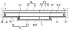
도 2는 도 1의 I-I'선에 따른 단면도이다.
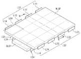
도 3a는 본 발명의 제1 실시예에 따른 표시 장치에 있어서 광원부와 도광부를 도시한 사시도이다.
도 3b는 도 3a의 II-II'선에 따른 단면도이다.
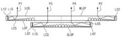
도 3c는 도 3a의 광원부와 도광부를 도시한 평면도이다.
도 4는 본 발명의 일 실시예에 따른 표시 장치를 나타낸 블록도이다.
도 5은 본 발명의 복수의 발광 영역을 도시한 도면이다.
도 6은 본 발명의 제2 실시예에 따른 백라이트 유닛을 나타낸 평면도이다.
도 7는 본 발명의 제3 실시예에 따른 백라이트 유닛을 나타낸 단면도이다.
도 8은 본 발명의 제4 실시예에 따른 백라이트 유닛을 나타낸 단면도이다.
도 9는 본 발명의 제5 실시예에 따른 표시 장치에 있어서 도 1의 I-I'선에 대응하는 단면도이다.
도 10a는 본 발명의 제5 실시예에 따른 표시 장치에 있어서 광원부와 도광부를 도시한 사시도이다.
도 10b는 도 10a의 III-III'선에 따른 단면도이다.
도 10c는 도 10a의 광원부와 도광부를 도시한 평면도이다.
도 11은 본 발명의 제6 실시예에 따른 표시 장치의 단면도로서, 도 1의 I-I'선에 대응하는 것이다.
도 12a는 본 발명의 제7 실시예에 따른 표시 장치에 있어서 광원부와 도광부를 도시한 사시도이다.
도 12b는 도 12a의 IV-IV'선에 따른 단면도이다.
도 12c는 도 12a의 광원부와 도광부를 표시한 평면도이다.
도 13a는 본 발명의 제8 실시예에 따른 표시 장치에 있어서 광원부와 도광부를 도시한 사시도이다.
도 13b는 도 13a의 V-V'선에 따른 단면도이다.
도 13c는 도 13a의 광원부와 도광부를 표시한 평면도이다.
도 14a, 도 14b, 및 도 14c는 각각 본 발명의 실시예들에 있어서 도광부에 형성된 출광 패턴을 도광판과 함께 확대하여 도시한 사시도, 측면도, 및 평면도이다.
도 15a 및 도 15b는 출광 패턴의 변형예들을 나타낸 단면도들이고, 도 15c 내지 도 15f는 출광 패턴의 변형예들을 나타낸 평면도들이다.
도 16은 본 발명의 따른 백라이트 유닛에 있어서 각 발광 영역의 단면의 휘도 시뮬레이션 그래프이다.
도 17a는 광 가이드 패턴을 설명하기 위한 광원부와 도광부의 사시도이다.
도 17b는 도 17a의 VI-VI'선에 따른 단면도이다.
도 17c는 도 17a의 VII-VII'선에 따른 단면도이다.
도 18a 및 도 18b는 각각 광 가이드 패턴의 다른 일례들을 설명하기 위한 백라이트 유닛의 사시도이다.1 is an exploded perspective view illustrating a display device according to a first exemplary embodiment of the present invention.
2 is a cross-sectional view taken along the line I-I 'of FIG.
3A is a perspective view illustrating a light source unit and a light guide unit in the display device according to the first exemplary embodiment of the present invention.
3B is a cross-sectional view taken along the line II-II 'of FIG. 3A.
3C is a plan view illustrating the light source unit and the light guide unit of FIG. 3A.
4 is a block diagram illustrating a display device according to an exemplary embodiment of the present invention.
5 is a diagram illustrating a plurality of light emitting regions of the present invention.
6 is a plan view illustrating a backlight unit according to a second exemplary embodiment of the present invention.
7 is a cross-sectional view illustrating a backlight unit according to a third embodiment of the present invention.
8 is a cross-sectional view illustrating a backlight unit according to a fourth embodiment of the present invention.
9 is a cross-sectional view taken along the line II ′ of FIG. 1 in the display device according to the fifth exemplary embodiment.
10A is a perspective view illustrating a light source unit and a light guide unit in a display device according to a fifth exemplary embodiment of the present invention.
FIG. 10B is a cross-sectional view taken along the line III-III ′ of FIG. 10A.
FIG. 10C is a plan view illustrating the light source unit and the light guide unit of FIG. 10A.
11 is a cross-sectional view of the display device according to the sixth exemplary embodiment, which corresponds to the line II ′ of FIG. 1.
12A is a perspective view illustrating a light source unit and a light guide unit in the display device according to the seventh exemplary embodiment.
12B is a cross-sectional view taken along line IV-IV 'of FIG. 12A.
12C is a plan view illustrating the light source unit and the light guide unit of FIG. 12A.
13A is a perspective view illustrating a light source unit and a light guide unit in a display device according to an eighth exemplary embodiment of the present invention.
FIG. 13B is a cross-sectional view taken along the line VV ′ of FIG. 13A.
FIG. 13C is a plan view illustrating the light source unit and the light guide unit of FIG. 13A.
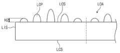
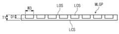
14A, 14B, and 14C are perspective views, side views, and plan views, respectively, illustrating an enlarged view of a light output pattern formed in a light guide portion together with a light guide plate in embodiments of the present invention.
15A and 15B are cross-sectional views illustrating modifications of the light emission pattern, and FIGS. 15C to 15F are plan views illustrating modifications of the light emission pattern.
16 is a luminance simulation graph of a cross section of each light emitting area in the backlight unit according to the present invention.
17A is a perspective view of a light source unit and a light guide unit for explaining the light guide pattern.
17B is a cross-sectional view taken along the line VI-VI 'of FIG. 17A.
FIG. 17C is a cross-sectional view taken along the line VII-VII ′ of FIG. 17A.
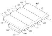
18A and 18B are perspective views of a backlight unit for explaining other examples of the light guide pattern, respectively.
본 발명은 다양한 변경을 가할 수 있고 여러 가지 형태를 가질 수 있는 바, 특정 실시예들을 도면에 예시하고 본문에 상세하게 설명하고자 한다. 그러나, 이는 본 발명을 특정한 개시 형태에 대해 한정하려는 것이 아니며, 본 발명의 사상 및 기술 범위에 포함되는 모든 변경, 균등물 내지 대체물을 포함하는 것으로 이해되어야 한다.The present invention is capable of various modifications and various forms, and specific embodiments are illustrated in the drawings and described in detail in the text. It should be understood, however, that the invention is not intended to be limited to the particular forms disclosed, but includes all modifications, equivalents, and alternatives falling within the spirit and scope of the invention.
이하, 첨부된 도면들을 참조하여 본 발명의 실시예들을 보다 상세히 설명하고자 한다.Hereinafter, embodiments of the present invention will be described in detail with reference to the accompanying drawings.
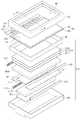
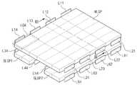
도 1은 본 발명의 제1 실시예에 따른 표시 장치를 도시한 분해 사시도이다. 도 2는 도 1의 I-I'선에 따른 단면도이다.1 is an exploded perspective view showing a display device according to a first embodiment of the present invention. 2 is a cross-sectional view taken along the line I-I 'of FIG.
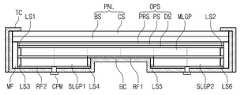
도 1 및 도 2를 참조하면, 상기 표시 장치는 표시 패널(PNL), 백라이트 유닛(BLU), 및 탑 샤시(TC)를 포함한다. 여기서, 설명의 편의를 위해, 상기 표시 장치에서 영상이 제공되는 방향을 상부 방향으로, 상기 상부 방향의 반대 방향을 하부 방향으로 하여 설명하나, 상기 상부 방향이나 하부 방향은 상대적인 개념으로서 다른 방향으로 변환될 수 있다.1 and 2, the display device includes a display panel PNL, a backlight unit BLU, and a top chassis TC. Here, for convenience of explanation, the direction in which the image is provided in the display device is referred to as an upward direction and the direction opposite to the upward direction is referred to as a downward direction, and the upward direction and the downward direction are converted into different directions .
상기 표시 패널(PNL)은 영상을 표시한다. 상기 표시 패널(PNL)은 수광형 표시 패널로서, 액정 표시 패널(liquid crystal display panel), 전기습윤 표시 패널(electrowetting display panel), 전기영동 표시 패널 (electrophoretic display panel), MEMS 표시 패널(microelectromechanical system display panel) 등을 포함할 수 있다. 본 실시예에서는 액정 표시 패널을 예로서 설명한다.The display panel (PNL) displays an image. The display panel PNL may be a light-receiving display panel, and may be a liquid crystal display panel, an electrowetting display panel, an electrophoretic display panel, a microelectromechanical system display panel and the like. In this embodiment, a liquid crystal display panel will be described as an example.
상기 표시 패널(PNL)은 서로 평행한 두 쌍의 변들을 가지는 직사각형의 판상으로 마련될 수 있으며, 두 쌍의 변들 중 어느 한 쌍의 변이 다른 한 쌍의 변보다 길게 제공될 수 있다. 상기 표시 패널(PNL)은 베이스 기판(BS)과, 상기 베이스 기판(BS)에 대향되는 대향 기판(CS), 및 상기 베이스 기판(BS)과 상기 대향 기판(CS) 사이에 형성된 액정층(미도시)을 포함한다. 상기 표시 패널(PNL)은 평면상에서 볼 때 영상이 표시되는 표시 영역(DA)과, 상기 표시 영역(DA)을 둘러싸며 영상이 표시되지 않은 비표시 영역(NDA)으로 이루어진다. 상기 비표시 영역(NDA)은 상기 탑 샤시(TC)에 의해 가려진다.The display panel PNL may be provided in a rectangular plate shape having two pairs of sides parallel to each other, and one pair of sides of the two pairs of sides may be provided longer than the other pair of sides. The display panel PNL includes a base substrate BS, a counter substrate CS opposed to the base substrate BS, and a liquid crystal layer (not shown) formed between the base substrate BS and the counter substrate CS Time). The display panel PNL includes a display area DA for displaying an image when viewed on a plane and a non-display area NDA for surrounding the display area DA and displaying no image. The non-display area NDA is covered by the top chassis TC.
본 발명의 일 실시예에 따르면, 상기 베이스 기판(BS)은 다수의 화소 전극들(미도시) 및 상기 화소 전극들과 일대일 대응하여 전기적으로 연결된 다수의 박막 트랜지스터(미도시)들을 포함할 수 있다. 각 박막 트랜지스터는 대응하는 화소 전극 측으로 제공되는 구동 신호를 스위칭한다. 또한, 상기 대향 기판(CS)은 상기 화소 전극들과 함께 상기 액정의 배열을 제어하는 전계를 형성하는 공통전극(미도시)을 포함할 수 있다. 상기 표시 패널(PNL)은 상기 액정층을 구동하여 전방으로 영상을 표시하는 역할을 한다.According to one embodiment of the present invention, the base substrate BS may include a plurality of pixel electrodes (not shown) and a plurality of thin film transistors (not shown) electrically connected to the pixel electrodes in a one-to-one correspondence . Each thin film transistor switches the driving signal provided to the corresponding pixel electrode side. In addition, the counter substrate CS may include a common electrode (not shown) for forming an electric field for controlling the arrangement of the liquid crystal together with the pixel electrodes. The display panel (PNL) drives the liquid crystal layer to display an image forward.
상기 표시 패널(PNL)에는 상기 구동 신호를 제공하는 구동칩(CH), 상기 구동칩(CH)이 실장되는 테이프 캐리어 패키지(Tape Carrier Package, TCP) 및 TCP를 통해 상기 표시 패널(PNL)과 전기적으로 연결되는 인쇄 회로 기판(PCB)이 제공될 수 있다. 도 1에 있어서, 상기 인쇄 회로 기판(PCB)은 상기 표시 패널(PNL)과 동일 평면에 도시되었으나, 후술할 보텀 샤시(BC)의 외부면에 배치될 수 있으며, 이 때, 상기 TCP가 상기 보텀 샤시(BC)의 외부면을 따라 구부러져 상기 표시 패널(PNL)과 상기 인쇄 회로 기판(PCB)을 이을 수 있다. 한편, 상기 구동칩(CH)은 외부 신호에 응답하여 상기 표시 패널(PNL)을 구동하기 위한 상기 구동 신호를 발생한다. 상기 외부 신호는 상기 인쇄회로 기판(PCB)으로부터 공급된 신호이고, 상기 외부 신호에는 영상 신호, 각종 제어신호 및 구동 전압 등이 포함될 수 있다.The display panel PNL is electrically connected to the display panel PNL through a TCP, a tape carrier package (TCP) on which the driving chip CH is mounted, a driving chip CH for providing the driving signal, A printed circuit board (PCB) may be provided. In FIG. 1, the printed circuit board PCB is illustrated on the same plane as the display panel PNL, but may be disposed on an outer surface of the bottom chassis BC, which will be described later. The display panel PNL and the printed circuit board PCB may be bent along the outer surface of the chassis BC. Meanwhile, the driving chip CH generates the driving signal for driving the display panel PNL in response to an external signal. The external signal is a signal supplied from the printed circuit board (PCB), and the external signal may include a video signal, various control signals, and a driving voltage.
상기 백라이트 유닛(BLU)는 상기 표시 패널(PNL)에 광을 제공하기 위한 것으로서, 상기 표시 패널(PNL)의 하부에 제공된다. 상기 백라이트 유닛(BLU)는 상기 표시 패널(PNL)을 지지하는 몰드 프레임(MF), 광을 출사하는 광원들이 포함된 광원부, 상기 광을 상기 표시 패널(PNL) 방향으로 인도하는 도광부, 상기 광의 효율을 높이기 위한 광학 시트들(OPS), 상기 광의 진행 방향을 변경하기 위한 반사 시트(RF1, RF2), 및 상기 표시 패널(PNL), 상기 몰드 프레임(MF), 상기 광원부, 상기 도광부, 상기 광학 시트들(OPS), 및 상기 반사 시트(RF1, RF2)를 수납하는 보텀 샤시(BC)를 포함한다.The backlight unit BLU is used to provide light to the display panel PNL and is provided below the display panel PNL. The backlight unit BLU may include a mold frame MF supporting the display panel PNL, a light source unit including light sources emitting light, a light guide unit guiding the light toward the display panel PNL, Optical sheets OPS for increasing efficiency, reflective sheets RF1 and RF2 for changing the traveling direction of the light, and the display panel PNL, the mold frame MF, the light source unit, the light guide unit, An optical sheet OPS and a bottom chassis BC for receiving the reflective sheets RF1 and RF2 are included.
상기 몰드 프레임(MF)은 상기 표시 패널(PNL)의 가장자리를 따라 제공되어 상기 표시 패널(PNL)의 하부에서 상기 표시 패널(PNL)을 지지한다. 상기 몰드 프레임(MF)은 상기 표시 패널(PNL) 이외의 구성요소, 예를 들어 상기 도광부, 상기 광원부, 상기 광학 시트들(OPS) 등을 고정하거나 지지하도록 하는 고정 부재, 예를 들어, 걸림턱(미도시)을 가질 수 있다. 상기 몰드 프레임(MF)은 상기 표시 패널(PNL)의 네 변에 대응하는 위치, 또는 상기 네 변의 적어도 일부에 대응하는 위치에 제공될 수 있다. 예를 들어, 상기 몰드 프레임(MF)은 상기 표시 패널(PNL)의 네 변에 대응하는 사각의 고리 형상을 가질 수 있으며, 또는, 상기 표시 패널(PNL)의 가장자리 중 세 변에 대응하는 ㄷ자 형상을 가질 수 있다. 상기 몰드 프레임(MF)은 단일 개수로 일체로 형성될 수 있으나 필요에 따라 복수로 형성되어 조립될 수 있다. 상기 몰드 프레임(MF)은 고분자 수지와 같은 유기 재료로 이루어질 수 있다. 그러나, 이에 한정되는 것은 아니며, 동일한 형상과 기능을 갖는다면 다른 재료로도 이루어질 수 있다.The mold frame MF is provided along an edge of the display panel PNL to support the display panel PNL at a lower portion of the display panel PNL. The mold frame MF is a fixing member for fixing or supporting a component other than the display panel PNL, for example, the light guide part, the light source part, the optical sheets OPS, and the like. It may have a jaw (not shown). The mold frame MF may be provided at a position corresponding to four sides of the display panel PNL, or at a position corresponding to at least a part of the four sides. For example, the mold frame MF may have a quadrangular ring shape corresponding to four sides of the display panel PNL, or may have a U-shaped shape corresponding to three sides of the edges of the display panel PNL Lt; / RTI > The mold frames MF may be integrally formed by a single number, but may be formed as a plurality of mold assemblies as required. The mold frame MF may be made of an organic material such as a polymer resin. However, the present invention is not limited thereto, and other materials may be used as long as they have the same shape and function.
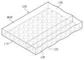
상기 도광부는 상기 표시 패널(PNL)의 하부에 제공되어, 상기 광을 상기 표시 패널(PNL) 방향으로 가이드한다. 상기 도광부는 상기 표시 패널(PNL)의 하부에 제공된 상기 표시 패널(PNL)과 실질적으로 동일 크기로 제공된 메인 도광판(MLGP)과, 상기 메인 도광판(MLGP)의 하부에 제공되며 상기 메인 도광판(MLGP)의 일부와 중첩하는 서브 도광판(SLGP)을 포함한다.The light guide portion is provided under the display panel PNL to guide the light toward the display panel PNL. The light guide portion is provided with a main light guide plate MLGP substantially the same size as the display panel PNL provided under the display panel PNL, and is provided under the main light guide plate MLGP and is provided under the main light guide plate MLGP. And a sub light guide plate (SLGP) overlapping with a portion of the light guide plate.
상기 메인 도광판(MLGP)과 상기 서브 도광판(SLGP)은 평면 상에서 볼 때 대략 사각형의 판상으로 제공된다. 상기 사각형의 각 변들은 상기 표시 패널(PNL)의 장변들과 단변들 중 어느 한 변과 평행할 수 있다.The main light guide plate MLGP and the sub light guide plate SLGP are provided in a substantially rectangular plate shape when viewed in plan view. Each side of the quadrangle may be parallel to any one of long sides and short sides of the display panel PNL.
상기 광원부는 상기 메인 도광판(MLGP)과 상기 서브 도광판(SLGP)으로 광을 제공한다. 상기 광원부에는 복수의 광원 블록들(LS1, LS3, LS3, LS4)과 상기 광원 블록들을 제어하는 광원부 제어 유닛이 연결될 수 있다. 도 4에서 후술되는 상기 광원부 제어 유닛(50)은 상기 표시 패널(PNL)에서 표시되는 영상을 분석하여 로컬 디밍 신호를 출력하고 상기 로컬 디밍 신호에 응답하여 상기 광원 그룹들 각각의 휘도를 개별 제어한다. 상기 광원 블록들은 상기 메인 도광판(MLGP)의 양측에 배치된 제1 광원 블록(LS1)과 제2 광원 블록(LS2), 및 상기 서브 도광판(SLGP)의 양측에 배치된 제3 광원 블록(LS3)과 제4 광원 블록(LS4)을 포함한다. 각 광원 블록은 복수의 광원들과, 상기 광원들을 지지하는 지지부를 포함한다. 상기 지지부는 상기 광원에 전원을 공급하고 제어하는 배선이 인쇄된 회로 기판일 수 있으며, 후술할 메인 도광판(MLGP) 및 서브 도광판(SLGP)의 입광면들을 따라 길게 연장된 직사각 형상의 판상일 수 있다. 상기 광원들은 점광원, 선광원, 또는 면광원 등이 다양하게 사용될 수 있으며 이에 한정되지는 않는다. 본 발명의 실시예에서는 일 예로서 LED(light emitting diode)를 점광원으로서 사용한 것을 도시하였다. 상기 LED는 복수 개로 제공되며 상기 기판 상에 상기 소정 방향을 따라 일렬로 배치될 수 있다. 여기서, 광원이라 함은 동일한 전원 라인에 연결되어 온/오프가 단일하게 구동되는 광원들의 단위를 뜻하는 것으로서, 출사되는 광량이 개별적으로 조절될 수 있는 최소 단위의 발광 단위를 의미한다. 따라서, 하나의 광원은 문자 그대로 하나의 광원, 예를 들어, 예를 들어, 하나의 LED를 포함할 수 있으나, 동시에 밝기가 조절되는 n개의 광원들(n은 자연수)로 이루어진 복수의 광원 그룹, 예를 들어, 복수의 LED들을 포함할 수 있다.The light source unit provides light to the main light guide plate MLGP and the sub light guide plate SLGP. A plurality of light source blocks LS1, LS3, LS3 and LS4 and a light source unit control unit for controlling the light source blocks may be connected to the light source unit. The light
본 발명의 제1 실시예에서는 상기 광원 블록들이 상기 인쇄 회로 기판과 상기 복수의 광원들로 이루어진 것을 도시하였으나, 이에 한정되는 것은 아니다. 즉, 상기 지지부는 생략될 수 있으며, 상기 지지부가 생략되는 경우에는 상기 광원들을 지지하는 별도의 지지 부재 및/또는 상기 광원들에 전원을 공급하는 별도의 배선이 마련될 수 있다.In the first embodiment of the present invention, the light source blocks are formed of the printed circuit board and the plurality of light sources, but are not limited thereto. That is, the support part may be omitted, and when the support part is omitted, a separate support member for supporting the light sources and / or a separate wiring for supplying power to the light sources may be provided.
상기 메인 도광판(MLGP), 상기 서브 도광판(SLGP), 및 상기 광원부에 대해서는 상세히 후술한다.The main light guide plate MLGP, the sub light guide plate SLGP, and the light source unit will be described in detail later.
상기 광학 시트(OPS)는 상기 도광부과 상기 표시 패널(PNL) 사이에 제공된다. 상기 광학 시트(OPS)는 상기 광원으로부터 나온 광을 제어하는 역할을 한다. 상기 광학 시트(OPS)는 상기 도광부 상에 적층된 확산 시트(DS), 프리즘 시트(PS) 및 보호 시트(PRS)를 포함한다.The optical sheet OPS is provided between the light guide portion and the display panel PNL. The optical sheet OPS serves to control the light emitted from the light source. The optical sheet OPS includes a diffusion sheet DS, a prism sheet PS, and a protective sheet PRS stacked on the light guide portion.
상기 확산 시트(DS)는 상기 광을 확산한다. 상기 프리즘 시트(PS)는 상기 확산 시트(DS)에서 확산된 빛을 상부의 표시 패널(PNL)의 평면에 수직한 방향으로 집광하는 역할을 수행한다. 상기 프리즘 시트(PS)를 통과한 빛은 거의 대부분 상기 표시 패널(PNL)에 수직하게 입사된다. 상기 보호 시트(PRS)는 상기 프리즘 시트(PS) 상에 위치한다. 상기 보호 시트(PRS)는 상기 프리즘 시트(PS)를 외부의 충격으로부터 보호한다. 본 실시예에서는 상기 광학 시트(OPS)가 상기 확산 시트(DS), 상기 프리즘 시트(PS), 및 상기 보호 시트(PRS)가 한 매씩 구비된 것을 예로 들었으나 이에 한정되는 것은 아니다. 상기 광학 시트(OPS)는 상기 확산시트, 상기 프리즘 시트(PS), 및 상기 보호 시트(PRS) 중 적어도 어느 하나를 복수 매 겹쳐서 사용할 수 있으며, 필요에 따라 어느 하나 이상의 시트를 생략할 수도 있다. 또한, 상기 확산 시트(DS), 상기 프리즘 시트(PS), 및 상기 보호 시트(PRS)는 순서를 바꾸어 적층할 수 있다.The diffusion sheet DS diffuses the light. The prism sheet PS functions to condense the light diffused in the diffusion sheet DS in a direction perpendicular to the plane of the upper display panel PNL. The light having passed through the prism sheet PS is almost vertically incident on the display panel PNL. The protective sheet PRS is positioned on the prism sheet PS. The protective sheet PRS protects the prism sheet PS from an external impact. The optical sheet OPS includes the diffusion sheet DS, the prism sheet PS, and the protection sheet PRS. However, the present invention is not limited thereto. The optical sheet OPS may be used by stacking at least one of the diffusion sheet, the prism sheet PS, and the protective sheet PRS in a plurality, and may omit any one or more sheets as necessary. In addition, the diffusion sheet DS, the prism sheet PS, and the protective sheet PRS may be laminated in order.
상기 반사 시트(RF1, RF2)는 상기 표시 패널(PNL) 방향으로 제공되지 않고 누설되는 광을 반사시켜 상기 표시 패널(PNL) 방향으로 광의 경로를 변경시키기 위한 것으로, 상기 도광부의 하부에 구비된다. 상기 반사 시트(RF1, RF2)는 상기 메인 도광판(MLGP)의 하부에 제공된 제1 반사 시트(RF1)와 상기 서브 도광판(SLGP)의 하부에 제공된 제2 반사 시트(RF2)를 포함한다. 상기 제1 반사 시트(RF1)와 상기 제2 반사 시트(RF2)는 상기 보텀 샤시(BC) 상에 구비되어 상기 광을 반사시킨다. 그 결과, 상기 제1 및 제2 반사 시트(RF1, RF2)에 의해 상기 표시 패널(PNL) 측으로 제공되는 광의 양이 증가된다. 상기 제1 반사 시트(RF1)는 상기 서브 도광판(SLGP)에 광을 제공하는 상기 제3 광원 블록(LS3)과 상기 제4 광원 블록(LS4)을 상부에서 커버함으로써, 상기 제3 광원 블록(LS3)과 상기 제4 광원 블록(LS4)으로부터 출사한 광이 곧바로 상기 메인 도광판(MLGP)으로 입사하는 것을 막는다.The reflective sheets RF1 and RF2 are not provided in the display panel PNL direction to reflect the leaked light and change the path of the light in the direction of the display panel PNL. The reflective sheets RF1 and RF2 include a first reflective sheet RF1 provided under the main light guide plate MLGP and a second reflective sheet RF2 provided under the sub light guide plate SLGP. The first reflective sheet RF1 and the second reflective sheet RF2 are provided on the bottom chassis BC to reflect the light. As a result, the amount of light provided to the display panel PNL side by the first and second reflective sheets RF1 and RF2 is increased. The first reflective sheet RF1 covers the third light source block LS3 and the fourth light source block LS4, which provide light to the sub light guide plate SLGP, to cover the third light source block LS3. ) And the light emitted from the fourth light source block LS4 are prevented from directly entering the main LGP.
상기 메인 도광판(MLGP)과 상기 서브 도광판(SLGP) 사이에는 투명 시트(TF)가 더 제공될 수 있다. 상기 투명 시트(TF)는 상기 메인 도광판(MLGP)의 하부에 제공되되, 상기 메인 도광판(MLGP)과 상기 서브 도광판(SLGP)의 중첩 영역에만 제공된다. 상기 메인 도광판(MLGP)의 하부 중 상기 서브 도광판(SLGP)가 제공되지 않는 부분에는 상술한 제1 반사 시트(RF1)이 제공된다. 여기서, 상기 투명 시트(TF)는 상기 제1 반사 시트(RF1)와 동일 평면 상에 제공되며, 상기 투명 시트(TF)와 상기 제1 반사 시트(RF1)이 제공된 영역은 상기 메인 도광판(MLGP)가 제공된 영역과 실질적으로 동일하다.A transparent sheet TF may be further provided between the main light guide plate MLGP and the sub light guide plate SLGP. The transparent sheet TF is provided under the main light guide plate MLGP, and is provided only in an overlapping region of the main light guide plate MLGP and the sub light guide plate SLGP. The above-described first reflective sheet RF1 is provided at a portion of the lower portion of the main LGP that is not provided with the sub LGP. Here, the transparent sheet TF is provided on the same plane as the first reflective sheet RF1, and the area where the transparent sheet TF and the first reflective sheet RF1 are provided is the main light guide plate MLGP. Is substantially the same as the area provided.
한편, 상기 투명 시트(TF)와 상기 제1 반사 시트(RF1)은 서로 분리되지 않는 일체로 제공될 수 있다. 이 경우, 상기 제1 반사 시트(RF1) 부분에는 반사 물질이 코팅되거나 라미네이트될 수 있다.Meanwhile, the transparent sheet TF and the first reflective sheet RF1 may be integrally provided without being separated from each other. In this case, a portion of the first reflective sheet RF1 may be coated or laminated with a reflective material.
상기 메인 도광판(MLGP)과 상기 서브 도광판(SLGP) 사이는 상기 제1 반사 시트(RF1)의 두께만큼 이격될 수 있는 바, 상기 투명 시트(TF)는 상기 제1 반사 시트(RF1)에 대응하는 두께를 가질 수 있다.The main light guide plate MLGP and the sub light guide plate SLGP may be spaced apart by the thickness of the first reflective sheet RF1, and the transparent sheet TF may correspond to the first reflective sheet RF1. It may have a thickness.
상기 투명 시트(TF)는 상기 메인 도광판(MLGP)과 상기 서브 도광판(SLGP)의 굴절률과 유사하거나 실질적으로 동일한 굴절률을 가질 수 있으며, 이 경우, 상기 서브 도광판(SLGP)으로부터 상기 메인 도광판(MLGP)으로 진행하는 광의 손실이 감소된다.The transparent sheet TF may have a refractive index that is similar to or substantially the same as that of the main LGP and the sub LGP. In this case, the main LGP may be formed from the sub LGP. Loss of light traveling to it is reduced.
상기 투명 시트(TF)는 상기 상기 메인 도광판(MLGP)과 상기 서브 도광판(SLGP)과 동일하거나 유사한 물질로 제조될 수 있다. 또한, 상기 투명 시트(TF)는 상기 상기 메인 도광판(MLGP) 및 상기 서브 도광판(SLGP)의 굴절률과 동일하거나 유사하다면 상기 상기 메인 도광판(MLGP) 및 상기 서브 도광판(SLGP)과 다른 물질로 제조될 수 있다. 예를 들어, 상기 투명 시트(TF)는 트리아세틸셀룰로오스 등의 아세테이트계 수지, 폴리에틸렌테레프탈레이트(PET), 폴리에틸렌나프탈레이트(PEN) 등의 폴리에스테르계 수지, 폴리에테르술폰계 수지, 폴리술폰계 수지, 폴리카보네이트계 수지, 폴리아미드계 수지, 폴리이미드계 수지, 폴리올레핀계 수지, 아크릴계 수지, 폴리노르보르넨계 수지, 셀룰로오스계 수지, 폴리아릴레이트계 수지, 폴리스티렌계 수지, 폴리비닐알콜계 수지, 폴리염화비닐계 수지, 폴리염화비닐리덴계 수지, 폴리아크릴계 수지 등으로 이루어질 수 있다. 또한, 상기 투명 시트(TF)는 상기 수지 중 어느 한 종으로 이루어질 수 있으나, 이에 한정되는 것은 아니며 두 종 이상의 수지로 이루어질 수도 있다.The transparent sheet TF may be made of the same or similar material as that of the main LGP and the sub LGP. In addition, the transparent sheet TF may be made of a material different from that of the main LGP and the sub LGP if the same or similar to the refractive indices of the main LGP and the sub LGP. Can be. For example, the transparent sheet (TF) may be a polyester resin such as acetate resin such as triacetyl cellulose, polyethylene terephthalate (PET), polyethylene naphthalate (PEN), polyether sulfone resin, or polysulfone resin. , Polycarbonate resin, polyamide resin, polyimide resin, polyolefin resin, acrylic resin, polynorbornene resin, cellulose resin, polyarylate resin, polystyrene resin, polyvinyl alcohol resin, polychloride It may be made of a vinyl resin, polyvinylidene chloride resin, polyacrylic resin, and the like. In addition, the transparent sheet TF may be made of any one of the above resins, but is not limited thereto and may be made of two or more resins.
상기 보텀 샤시(BC)는 상기 백라이트 유닛(BLU) 하부에 제공되어, 상기 백라이트 유닛(BLU)의 구성 요소들을 수납한다. 상기 보텀 샤시(BC)는 상기 반사 시트(RF1, RF2)의 하부에 상기 반사 시트(RF1, RF2)의 배면에 평행한 바닥부와, 상기 바닥부로부터 상방 절곡되어 연장된 측벽부를 포함할 수 있다. 상기 바닥부와 상기 측벽부로 이루어진 공간에 상기 백라이트 유닛(BLU)이 수납된다. 상기 바닥부는 상기 메인 도광판(MLGP)과 상기 서브 도광판(SLGP) 의 하부 형상에 따라 굴곡지게 형성될 수 있으며, 이 경우, 상기 서브 도광판(SLGP)이 제공되지 않은 상기 보텀 샤시(BC)의 외부면에는 상기한 인쇄 회로 기판(PCB) 등이 제공될 수 있다. 이에 따라, 상기 표시 장치의 전체 부피가 크게 증가함이 없이 상기 인쇄 회로 기판(PCB)과 같은 구성 요소를 컴팩트하게 적재할 수 있다.The bottom chassis BC is provided under the backlight unit BLU to accommodate components of the backlight unit BLU. The bottom chassis BC may include a bottom portion parallel to the rear surface of the reflective sheets RF1 and RF2 and a sidewall portion bent upwardly from the bottom portion under the reflective sheets RF1 and RF2. . The backlight unit BLU is accommodated in a space formed by the bottom part and the side wall part. The bottom portion may be formed to be bent according to the lower shapes of the main LGP and the sub LGP. In this case, an outer surface of the bottom chassis BC is not provided with the sub LGP. The printed circuit board (PCB) and the like may be provided. Accordingly, a component such as the printed circuit board (PCB) may be compactly loaded without greatly increasing the overall volume of the display device.
상기 탑 샤시(TC)는 상기 표시 패널(PNL)의 상부에 제공된다. 상기 탑 샤시(TC)는 상기 표시 패널(PNL)의 전면 가장자리를 지지하며, 상기 몰드 프레임(MF)의 측면 또는 상기 보텀 샤시(BC)의 측면을 커버할 수 있다. 상기 탑 샤시(TC)에는 상기 표시 패널(PNL)의 표시 영역(DA)을 노출시키는 표시창(WD)이 형성되어 있다.The top chassis TC is provided on top of the display panel PNL. The top chassis TC supports the front edge of the display panel PNL and can cover the side surface of the mold frame MF or the side surface of the bottom chassis BC. A display window WD for exposing the display area DA of the display panel PNL is formed on the top chassis TC.
이하, 상기 백라이트 유닛(BLU)에 있어서, 상기 광원부와 상기 도광부에 대해 상세하게 설명한다.Hereinafter, the light source unit and the light guide unit will be described in detail in the backlight unit BLU.
도 3a는 본 발명의 제1 실시예에 따른 표시 장치에 있어서 광원부와 도광부를 도시한 사시도이다. 도 3b는 도 3a의 II-II'선에 따른 단면도이다. 도 3c는 도 3a의 광원부와 도광부를 도시한 평면도로서, 서로 다른 층에 배치되는 메인 도광판(MLGP), 서브 도광판(SLGP), 및 광원부를 편의상 동일 평면에 나란히 도시한 것이다. 상기 메인 도광판(MLGP)의 일부와 상기 서브 도광판(SLGP)은 중첩됨으로써 평면상에서 동일한 행과 열을 표시하기 때문에, 상기 중첩된 일부 행과 열은 동일한 부호로 표시되었다.3A is a perspective view illustrating a light source unit and a light guide unit in the display device according to the first exemplary embodiment of the present invention. 3B is a cross-sectional view taken along the line II-II 'of FIG. 3A. FIG. 3C is a plan view illustrating the light source unit and the light guide unit of FIG. 3A, and the main light guide plate MLGP, the sub light guide plate SLGP, and the light source unit disposed on different layers are side-by-side for convenience. Since a part of the main LGP MLGP and the sub LGP SLGP display the same rows and columns on a plane by overlapping, the overlapping some rows and columns are denoted by the same reference numerals.
도 3a, 도 3b, 및 도 3c를 참조하면, 본 발명의 제1 실시예에 따른 백라이트 유닛은 표시 패널(PNL)에 광을 제공하기 위한 광원부와, 상기 광을 상기 표시 패널(PNL) 방향으로 인도하는 도광부를 포함한다.3A, 3B, and 3C, a backlight unit according to a first embodiment of the present invention includes a light source unit for providing light to a display panel PNL, and the light toward the display panel PNL. It includes a light guide to guide.
상기 도광부는 메인 도광판(MLGP)과, 상기 메인 도광판(MLGP)보다 작은 크기로 제공되는 서브 도광판(SLGP)을 포함한다. 평면 상에서 볼 때, 상기 메인 도광판(MLGP)과 상기 서브 도광판(SLGP)은 중첩된다. 여기서, 상기 메인 도광판(MLGP) 및 상기 서브 도광판(SLGP)은 표시 패널(PNL) 측에서 보았을 때 하나의 도광판만이 존재하는 것처럼 서로 중첩되어 있다. 상기 도광부는 평면상에서 볼 때 복수의 발광 영역들(LOA)을 구성한다. 상기 발광 영역들(LOA)은 매트릭스 형태로 배열되며 상기 표시 패널(PNL)의 대응하는 표시 영역(DA)에 각각 광을 제공한다. 도 3a, 도 3b, 및 도 3c에서는 상기 발광 영역들(LOA)이 MxN의 매트릭스를 이룰 때 M=4, N=4인 경우를 도시한 것이다. 이하, 상기 메인 도광판(MLGP)과 상기 서브 도광판(SLGP)은 상기 발광 영역들(LOA)에 대응하여 구비되므로, 상기 메인 도광판(MLGP)과 상기 서브 도광판(SLGP)에서의 특정 영역(출광 영역들 및/또는 투과 영역들)의 위치는 평면 상에서 볼 때의 상기 발광 영역들(LOA)을 행과 열을 기준으로 한다.The light guide part includes a main light guide plate MLGP and a sub light guide plate SLGP provided in a smaller size than the main light guide plate MLGP. In the plan view, the main light guide plate MLGP and the sub light guide plate SLGP overlap. The main light guide plate MLGP and the sub light guide plate SLGP overlap each other as if only one light guide plate exists when viewed from the display panel PNL side. The light guide portion constitutes a plurality of light emitting regions LOA in plan view. The light emitting regions LOA are arranged in a matrix and provide light to corresponding display regions DA of the display panel PNL, respectively. 3A, 3B, and 3C show the case where M = 4 and N = 4 when the light emitting regions LOA form a matrix of M × N. Hereinafter, since the main light guide plate MLGP and the sub light guide plate SLGP are provided to correspond to the light emitting regions LOA, specific regions (light emission areas) in the main light guide plate MLGP and the sub light guide plate SLGP are provided. And / or transmissive regions) are based on rows and columns of the light emitting regions LOA in plan view.
상기 메인 도광판(MLGP)과 상기 서브 도광판(SLGP) 각각은 상기 광원부와 인접하여 광이 입사되는 입광면(LIS)과, 일 단부가 상기 입광면(LIS)과 연결되고 광이 출사되는 면인 출광면(LOS)과, 상기 입광면(LIS)과 연결되며 상기 출광면(LOS)과 대향하는 대향면(LCS)을 포함한다. 상기 입광면(LIS)은 상기 광원부와 대향하며 상기 광원부로부터 출사된 광이 입사된다.Each of the main light guide plate MLGP and the sub light guide plate SLGP has a light incident surface LIS in which light is incident adjacent to the light source unit, and an light exit surface of which one end is connected to the light incident surface LIS and the light is emitted. And an opposing surface LCS connected to the light emitting surface LOS and facing the light emitting surface LOS. The light incident surface LIS is opposite to the light source unit and light emitted from the light source unit is incident.
상기 입광면(LIS) 상에는 상기 광원부로부터의 광의 입사 효율을 높이기 위한 입사 패턴이 추가될 수 있다. 상기 입사 패턴은 상기 입광면(LIS)으로부터 돌출되거나 함몰되도록 형성된 돌기 패턴들일 수 있다.An incident pattern may be added on the light incident surface LIS to increase the incident efficiency of the light from the light source unit. The incident patterns may be protrusion patterns formed to protrude or recess from the light incident surface LIS.
상기 입광면(LIS)으로 입사된 광은 상기 메인 도광판(MLGP) 또는 상기 서브 도광판(SLGP) 내에서 복수 회 반사되면서 진행하며, 상기 출광면(LOS)을 통해 상기 표시 패널(PNL) 방향, 즉, 상부 방향으로 출광된다. 여기서, 상기 광원부가 복수의 광원 블록들로 제공되는 경우, 상기 입광면(LIS) 또한 상기 광원 블록들에 대응하여 복수로 제공될 수 있다.The light incident on the light incident surface LIS is reflected a plurality of times in the main light guide plate MLGP or the sub light guide plate SLGP, and is directed toward the display panel PNL through the light exit surface LOS. , Light is emitted upward. Here, when the light source unit is provided with a plurality of light source blocks, the light incident surface LIS may also be provided in plurality corresponding to the light source blocks.
상기 메인 도광판(MLGP)은 상기 표시 패널(PNL)의 표시 영역에 대응하는 영역에 복수의 출광 영역들(A1)과 복수의 투과 영역들(B1)을 포함한다. 상기 출광 영역들(A1)은 상기 광원부로부터 제공된 광을 표시 패널(PNL)로 제공하기 위한 출광 패턴(LOP)이 제공된 영역이다. 상기 출광 패턴(LOP)은 상기 메인 도광판(MLGP) 내에서 진행하는 광의 경로를 변경(예를 들어, 반사)시킴으로써 상기 출광 패턴(LOP)이 형성된 영역에 대응하는 상기 출광면(LOS)으로 광을 출사하게 하는 패턴을 말한다(이에 대한 상세한 설명은 도면과 함께 후술한다). 상기 출광 패턴(LOP)은 상기 메인 도광판(MLGP)의 주로 대향면(LCS)에 형성된다. 상기 광원부로부터 상기 메인 도광판(MLGP) 내로 진행하는 광의 진로는 상기 출광 패턴(LOP)에 의해 상기 표시 패널(PNL) 방향으로 변경된다. 다만, 본 발명이 이에 한정되는 것은 아니며, 상기 출광 패턴(LOP)은 상기 출광면(LOS)에 형성될 수도 있다.The main LGP MLGP includes a plurality of light emitting regions A1 and a plurality of transmissive regions B1 in a region corresponding to the display region of the display panel PNL. The light exit areas A1 are areas provided with a light exit pattern LOP for providing light provided from the light source unit to the display panel PNL. The light exit pattern LOP is configured to change (eg, reflect) the path of the light traveling in the main LGP MLGP to direct light to the light exit surface LOS corresponding to an area where the light exit pattern LOP is formed. Refers to a pattern that causes it to exit (a detailed description thereof will be described later in conjunction with the drawings). The light exit pattern LOP is formed mainly on the opposing surface LCS of the main light guide plate MLGP. The path of the light traveling from the light source to the main LGP MLGP is changed in the direction of the display panel PNL by the light exit pattern LOP. However, the present invention is not limited thereto, and the light exit pattern LOP may be formed on the light exit surface LOS.
상기 투과 영역들(B1)은 상기 출광 패턴(LOP)이 제공되지 않은 영역으로서, 하부 방향으로부터 상부 방향으로 진행하는 광, 즉, 상기 표시 패널(PNL) 방향으로 진행하는 광은 투과시키나, 상기 출광면(LOS)에 평행하거나 비스듬하게 제공되는 광의 대부분(즉 임계각에 이르지 못한 광)을 반사시키는 영역이다.The transmissive regions B1 are regions in which the light exit pattern LOP is not provided and transmit light traveling from a lower direction to an upper direction, that is, light traveling toward the display panel PNL. The area reflects most of the light (ie, light not reaching the critical angle) provided parallel or obliquely to the light plane (LOS).
상기 서브 도광판(SLGP)은 상기 발광 영역들(LOA)의 일부에 대응하여 중첩한다. 상기 서브 도광판(SLGP)은 상기 메인 도광판(MLGP)의 상기 투과 영역들(B1)에 대응하는 출광 영역들(A2)을 가지며 별도의 투과 영역들이 없다.The sub light guide plate SLGP overlaps a portion of the light emitting regions LOA. The sub light guide plate SLGP has light exit areas A2 corresponding to the transmission areas B1 of the main light guide plate MLGP, and there are no separate transmission areas.
상기 메인 도광판(MLGP)의 양측과 상기 서브 도광판(SLGP)의 양측에는 상기 광원부가 배치된다. 구체적으로, 상기 메인 도광판(MLGP)의 행 방향 양측에는 상기 메인 도광판(MLGP)을 사이에 두고 서로 마주보는 제1 광원 블록(LS1)과 제2 광원 블록(LS2)이 제공된다. 상기 서브 도광판(SLGP)의 행 방향 양측에는 상기 서브 도광판(SLGP)을 사이에 두고 서로 마주보는 제3 광원 블록(LS3)과 제4 광원 블록(LS4)이 제공된다. 상기 제3 광원 블록(LS3)과 상기 제4 광원 블록(LS4) 각각은 상기 제1 광원 블록(LS1) 및 상기 제2 광원 블록(LS2)과 동일한 방향인 열 방향으로 연장된다.The light source unit may be disposed on both sides of the main LGP and the sub LGP. Specifically, the first light source block LS1 and the second light source block LS2 facing each other with the main light guide plate MLGP interposed therebetween are provided at both sides of the row LGP in the row direction. The third light source block LS3 and the fourth light source block LS4 facing each other with the sub light guide plate SLGP interposed therebetween are provided at both sides of the row light guide plate SLGP in the row direction. Each of the third light source block LS3 and the fourth light source block LS4 extends in a column direction in the same direction as the first light source block LS1 and the second light source block LS2.
상기 제1 광원 블록(LS1) 내지 상기 제4 광원 블록(LS4) 각각은 열 방향으로 연장되며, 상기 제1 광원 블록(LS1) 내지 상기 제4 광원 블록(LS4)은 각각 상기 행들에 대응하여 M개(본 실시예에서는 M=4)의 광원들을 갖는다. 즉, 상기 제1 광원 블록(LS1)은 L11, L12, L13, L14의 광원들을 가지며, 상기 제2 광원 블록(LS2)은 L21, L22, L23, L24의 광원들을, 상기 제3 광원 블록(LS3)은 L31, L32, L33, L34의 광원들을, 상기 제4 광원 블록(LS4)은 L41, L42, L43, L44의 광원들을 갖는다. 상기 제1 광원 블록(LS1) 내지 상기 제4 광원 블록(LS4)의 각 광원은 인접한 열의 상기 발광 영역들(LOA)에 일대일로 대응된다. 예를 들어, 상기 제1 광원 블록(LS1)의 L11, L12, L13, L14 광원들은 순서대로 제1 열(C1)의 제1 행(R1), 제2 행(R2), 제3 행(R3), 및 제4 행(R4)의 발광 영역들과 일대일로 대응한다. 이하, 각 광원에 있어서 숫자들 중 앞의 것은 각 광원 블록의 숫자를 의미하며, 뒤의 것은 각 광원 블록에서의 대응하는 행의 숫자를 의미한다. 예를 들어, L23의 경우, 제2 광원 블록(LS2)의 제3 행(R3)의 광원을 의미한다. 여기서, 상기 각 광원은 하나의 광원만으로 이루어질 수도 있으나, 이에 한정되는 것은 아니며, 복수의 광원들, 예를 들어, n개(n은 자연수)의 광원들을 포함하는 광원 그룹일 수도 있다.Each of the first light source block LS1 to the fourth light source block LS4 extends in a column direction, and the first light source block LS1 to the fourth light source block LS4 respectively correspond to the rows. Light sources (M = 4 in this embodiment). That is, the first light source block LS1 has light sources of L11, L12, L13, and L14, and the second light source block LS2 receives light sources of L21, L22, L23, and L24, and the third light source block LS3. ) Has light sources of L31, L32, L33, L34, and the fourth light source block LS4 has light sources of L41, L42, L43, and L44. Each light source of the first light source block LS1 to the fourth light source block LS4 corresponds one-to-one to the light emitting regions LOA in an adjacent column. For example, the light sources L11, L12, L13, and L14 of the first light source block LS1 are sequentially arranged in the first row R1, the second row R2, and the third row R3 of the first column C1. ) And the light emitting regions of the fourth row R4 in a one-to-one correspondence. Hereinafter, in each light source, the former means the number of each light source block, and the latter means the number of the corresponding row in each light source block. For example, in the case of L23, it means the light source of the 3rd row R3 of the 2nd light source block LS2. Here, each light source may be formed of only one light source, but is not limited thereto, and may be a light source group including a plurality of light sources, for example, n light sources (n is a natural number).
상기 서브 도광판(SLGP)에 있어서, 상기 출광 영역들(A2)은 상기 서브 도광판(SLGP)에 있어서의 출광 패턴(LOP)이 형성된 영역을 의미한다. 이하, 상기 메인 도광판(MLGP)에서의 출광 영역들(A1)은 상기 서브 도광판(SLGP)의 출광 영역들(A1)과 구별하기 위해 제1 출광 영역들(A1)로 지칭하며, 상기 서브 도광판(SLGP)의 출광 영역들(A2)은 제2 출광 영역들(A2)로 지칭한다.In the sub light guide plate SLGP, the light exit areas A2 mean areas in which the light exit pattern LOP is formed in the sub light guide plate SLGP. Hereinafter, the light exit areas A1 of the main LGP are referred to as first light exit areas A1 to distinguish them from the light exit areas A1 of the sub LGP. The light exit areas A2 of the SLGP are referred to as second light exit areas A2.
상기 제2 출광 영역들(A2)은 상기 제1 출광 영역들(A1)과 마찬가지로 상기 광원부의 배열에 따라 대응하는 열들에 배치된다. 본 발명의 제1 실시예에 있어서, 상기 광원부는 상기 서브 도광판(SLGP)에 대해 상기 열 방향으로 배열된 상기 제3 광원 블록(LS3)과 상기 제4 광원 블록(LS4)을 포함하며, 상기 제2 출광 영역들(A2)은 2개의 열, 즉, 상기 제3 광원 블록(LS3)에 대응하는 하나의 열과, 상기 제4 광원 블록(LS4)에 대응하는 다른 하나의 열에 배치된다. 이에 따라, 상기 발광 영역들(LOA)에 있어서, 상기 메인 도광판(MLGP)의 출광 패턴(LOP)이 형성된 영역들은 서브 도광판(SLGP)의 출광 패턴(LOP)이 형성된 영역들과 중첩되지 않는다. 그 결과, 상기 제1 출광 영역들(A1)과 상기 제2 출광 영역들(A2)는 서로 중첩하지 않으면서 평면상에 배열되므로, 상기 도광부의 상부 즉, 사용자가 상기 표시 패널(PNL) 측에서 도광부를 볼 때에는 상기 도광부의 전면(whole surface)에 상기 출광 패턴(LOP)이 배치된 것처럼 보인다. 상기 도광부의 상기 출광 패턴(LOP)이 형성된 영역의 면적의 합이 표시 패널(PNL)의 표시 영역(DSP)에 대응되는 상기 도광부의 전체 면적과 일치하도록 형성된다. 본 발명의 제1 실시예에서는, 도 3a, 도 3b, 및 도 3c에 도시된 바와 같이, 상기 메인 도광판(MLGP)이 4개의 행들(R1, R2, R3, R4)과 4개의 열들(C1, C2, C3, C4)을 가질 때, 상기 서브 도광판(SLGP)은 4개의 행들(R1, R2, R3, R4)과 2개의 열들(C2, C3)을 가진 것을 도시하였다. 여기서, 상기 메인 도광판(MLGP)에 있어서, 상기 제1 출광 영역들(A1)은 제1 열(C1) 및 제4 열(C4)의 발광 영역들(LOA)에 대응하며, 상기 투과 영역들(B1)은 제2 열(C2) 및 제3 열(C3)의 발광 영역들(LOA)에 대응한다. 상기 서브 도광판(SLGP)에 있어서, 상기 제2 출광 영역(A2)은 상기 발광 영역들(LOA) 중 상기 투과 영역들(B1)에 해당하는 제2 열(C2) 및 제3 열(C3)의 발광 영역들(LOA)에 대응한다.The second light emitting regions A2 are disposed in corresponding columns according to the arrangement of the light source unit, similarly to the first light emitting regions A1. In a first embodiment of the present invention, the light source unit includes the third light source block LS3 and the fourth light source block LS4 arranged in the column direction with respect to the sub light guide plate SLGP. The two light emitting regions A2 are disposed in two columns, one column corresponding to the third light source block LS3 and the other column corresponding to the fourth light source block LS4. Accordingly, in the light emitting regions LOA, regions in which the light exit pattern LOP of the main LGP is formed does not overlap with regions in which the light exit pattern LOP of the sub LGP is formed. As a result, since the first light emitting regions A1 and the second light emitting regions A2 are arranged on a plane without overlapping with each other, the first light emitting regions A1 and the second light emitting regions A2 are arranged on a plane, that is, the user is placed on the display panel PNL side. When the light guide portion is viewed, the light exit pattern LOP may be disposed on the whole surface of the light guide portion. The sum of the areas of the area where the light exit pattern LOP is formed in the light guide part is formed to match the total area of the light guide part corresponding to the display area DSP of the display panel PNL. In the first embodiment of the present invention, as shown in FIGS. 3A, 3B, and 3C, the main LGP has four rows R1, R2, R3, and R4 and four columns C1, When having C2, C3, C4, the sub light guide plate SLGP is shown with four rows R1, R2, R3, R4 and two columns C2, C3. In the main light guide plate MLGP, the first light emitting regions A1 correspond to the light emitting regions LOA of the first column C1 and the fourth column C4, and the transmission regions B1 corresponds to the light emitting regions LOA of the second column C2 and the third column C3. In the sub light guide plate SLGP, the second light emitting area A2 may include a second column C2 and a third column C3 corresponding to the transmission areas B1 of the light emitting areas LOA. Corresponding to the light emitting regions LOA.
본 발명의 제1 실시예에 있어서, 상기 제1 출광 영역들(A1)의 하부에는 상기 제1 반사 시트(RF1)이 제공되고, 상기 제2 출광 영역들(A2)의 하부에는 제2 반사 시트(RF2)이 제공된다. 상기 제1 반사 시트(RF1)은 양면 반사 시트일 수 있으며, 상기 제2 반사 시트(RF2)은 상면만 반사하는 일면 반사 시트일 수 있다. 여기서, 상기 제3 광원 블록(LS3)들과 상기 제4 광원 블록(LS4)들은 평면 상에서 볼 때 상기 발광 영역들(LOA) 중 상기 제1 출광 영역(A1) 내에 배치된다. 그러나, 상기 제1 출광 영역(A1)의 하부에는 도 1 및 도 2에서 도시된 바와 같이 제1 반사 시트(RF1)가 제공되므로, 상기 제3 광원 블록(LS3)들과 상기 제4 광원 블록(LS4)들로부터 출사된 광은 상기 제1 반사 시트(RF1)에 의해 반사되어 상기 제2 출광 영역(A2)으로만 진행한다. 그 결과, 상기 제3 광원 블록(LS3)들과 상기 제4 광원 블록(LS4)들로부터 광이 출사된다고 해도 수직 상방에 위치한 상기 제1 출광 영역(A1)으로 곧바로 진행하지 않는다.In the first embodiment of the present invention, the first reflective sheet RF1 is provided under the first light emitting regions A1, and the second reflective sheet is under the second light emitting regions A2. (RF2) is provided. The first reflective sheet RF1 may be a double-sided reflective sheet, and the second reflective sheet RF2 may be a one-side reflective sheet that reflects only an upper surface. Here, the third light source blocks LS3 and the fourth light source blocks LS4 are disposed in the first light emitting area A1 of the light emitting areas LOA when viewed in plan view. However, since the first reflective sheet RF1 is provided under the first light emitting area A1 as shown in FIGS. 1 and 2, the third light source blocks LS3 and the fourth light source block ( The light emitted from LS4) is reflected by the first reflective sheet RF1 and proceeds only to the second light emitting area A2. As a result, even if light is emitted from the third light source blocks LS3 and the fourth light source blocks LS4, the light does not immediately proceed to the first light emission area A1 located vertically upward.
상기한 구조를 갖는 백라이트 유닛에 있어서, 상기 광원부와 상기 도광부에 있어서의 광의 진행 경로를 도 3b와 도 5를 참조하여 설명하면 다음과 같다.In the backlight unit having the above-described structure, the path of the light in the light source unit and the light guide unit will be described with reference to FIGS. 3B and 5.
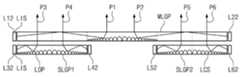
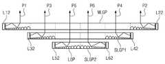
상기 제1 광원 블록(LS1)에서 출사된 제1 광(P1)은 상기 메인 도광판(MLGP)의 입광면(LIS)을 통해 상기 메인 도광판(MLGP) 내로 입사한다. 상기 제1 광(P1)은 상기 메인 도광판(MLGP) 내의 출광 영역들(A1) 중 가장 가까운 영역들(즉, 제1 열(C1)의 발광 영역들(LOA))에서 상기 출광 패턴(LOP) 및 제1 반사 시트(RF1)에 의해 상기 표시 패널(PNL) 방향으로 진행 경로가 변경된다. 이에 따라, 상기 제1 광(P1)은 상기 메인 도광판(MLGP)의 출광면(LOS)을 통해 상기 표시 패널(PNL) 방향으로 진행한다.The first light P1 emitted from the first light source block LS1 is incident into the main light guide plate MLGP through the light incident surface LIS of the main light guide plate MLGP. The first light P1 may be disposed in the light emitting pattern LOP in the closest regions among the light emitting regions A1 in the main LGP MLGP (ie, the light emitting regions LOA of the first column C1). And a traveling path in the direction of the display panel PNL by the first reflective sheet RF1. Accordingly, the first light P1 travels in the direction of the display panel PNL through the light exit surface LOS of the main LGP MLGP.
상기 제2 광원 블록(LS2)에서 출사된 제2 광(P2)은 상기 메인 도광판(MLGP)의 입광면(LIS)을 통해 상기 메인 도광판(MLGP) 내로 입사하며, 상기 메인 도광판(MLGP) 내의 출광 영역들(A1) 중 가장 가까운 영역들(즉, 제4열의 발광 영역들(LOA))에서 상기 출광 패턴(LOP) 및 제1 반사 시트(RF1)에 의해 상기 표시 패널(PNL) 방향으로 진행 경로가 변경된다. 이에 따라 상기 제2 광(P2)은 상기 메인 도광판(MLGP)의 출광면(LOS)을 통해 상기 표시 패널(PNL) 방향으로 진행한다.The second light P2 emitted from the second light source block LS2 is incident into the main light guide plate MLGP through the light incident surface LIS of the main light guide plate MLGP, and is emitted from the main light guide plate MLGP. A path traveling in the direction of the display panel PNL by the light emission pattern LOP and the first reflective sheet RF1 in the nearest areas among the areas A1 (that is, the light emitting areas LOA in the fourth row). Is changed. Accordingly, the second light P2 travels toward the display panel PNL through the light exit surface LOS of the main LGP MLGP.
상기 제3 광원 블록(LS3)에서 출사된 제3 광(P3)은 상기 서브 도광판(SLGP)의 입광면(LIS)을 통해 상기 서브 도광판(SLGP) 내로 입사하며, 상기 서브 도광판(SLGP) 내의 출광 영역들(A1) 중 가장 가까운 영역들(즉, 제2열의 발광 영역들(LOA))에서 상기 출광 패턴(LOP) 및 제2 반사 시트(RF2)에 의해 상기 표시 패널(PNL) 방향으로 진행 경로가 변경된다. 이에 따라 제3 광(P3)은 상기 서브 도광판(SLGP)의 출광면(LOS)을 통해 상기 메인 도광판(MLGP)의 투과 영역들(B1)(제2 열(C2)의 발광 영역들(LOA))로 진행한다. 여기서, 상기 제3 광(P3)은 상기 서브 도광판(SLGP)의 출광면(LOS), 상기 메인 도광판(MLGP)의 대향면(LCS), 및 상기 메인 도광판(MLGP)의 출광면(LOS)에 실질적으로 수직한 방향으로 진행하기 때문에 상기 메인 도광판(MLGP) 내에서 반사 없이 곧바로 상부 방향으로 투과된다. 그 결과, 상기 제3 광(P3)이 상기 표시 패널(PNL)에 제공된다.The third light P3 emitted from the third light source block LS3 enters the sub light guide plate SLGP through the light incident surface LIS of the sub light guide plate SLGP, and emits light in the sub light guide plate SLGP. A path traveling in the direction of the display panel PNL by the light emission pattern LOP and the second reflective sheet RF2 in the nearest regions among the regions A1 (that is, the light emitting regions LOA in the second row). Is changed. Accordingly, the third light P3 transmits the light emitting regions LO1 of the main LGP MLGP through the light emitting surface LOS of the sub LGP SLGP (the light emitting regions LOA of the second column C2). Proceed to). The third light P3 may be disposed on the light exit surface LOS of the sub LGP, the opposite surface LCS of the MLGP, and the light exit surface LOS of the main LGP. As it travels in a substantially vertical direction, it is transmitted directly in the main light guide plate MLGP without reflection in the upper direction. As a result, the third light P3 is provided to the display panel PNL.
상기 제4 광원 블록(LS4)에서 출사된 제4 광(P4)은 상기 서브 도광판(SLGP)의 입광면(LIS)을 통해 상기 서브 도광판(SLGP) 내로 입사하며, 상기 서브 도광판(SLGP) 내의 출광 영역들(A1) 중 가장 가까운 영역들(즉, 제3 열(C3)의 발광 영역들(LOA))에서 상기 출광 패턴(LOP) 및 제2 반사 시트(RF2)에 의해 상기 표시 패널(PNL) 방향으로 진행 경로가 변경된다. 이에 따라 제3 광(P3)은 상기 서브 도광판(SLGP)의 출광면(LOS)을 통해 상기 메인 도광판(MLGP)의 투과 영역들(B1)(제3열의 발광 영역들(LOA))로 진행한다. 여기서, 상기 제3 광(P3)은 상기 서브 도광판(SLGP)의 출광면(LOS), 상기 메인 도광판(MLGP)의 대향면(LCS), 및 상기 메인 도광판(MLGP)의 출광면(LOS)에 실질적으로 수직한 방향으로 진행하기 때문에 상기 메인 도광판(MLGP) 내에서 반사 없이 곧바로 투과된다. 그 결과, 상기 제4 광(P4)이 상기 표시 패널(PNL)에 제공된다.The fourth light P4 emitted from the fourth light source block LS4 enters the sub light guide plate SLGP through the light incident surface LIS of the sub light guide plate SLGP, and emits light in the sub light guide plate SLGP. The display panel PNL by the light emission pattern LOP and the second reflective sheet RF2 in the closest regions of the regions A1 (that is, the light emitting regions LOA of the third column C3). The travel path changes in the direction. Accordingly, the third light P3 proceeds to the transmission areas B1 (the third row of light emitting areas LOA) of the main light guide plate MLGP through the light exit surface LOS of the sub light guide plate SLGP. . The third light P3 may be disposed on the light exit surface LOS of the sub LGP, the opposite surface LCS of the MLGP, and the light exit surface LOS of the main LGP. As it travels in a substantially vertical direction, it is directly transmitted without reflection in the main LGP. As a result, the fourth light P4 is provided to the display panel PNL.
여기서, 상기 제1 광원 블록(LS1) 내지 상기 제4 광원 블록(LS4)의 광원들은 각각 대응하는 상기 발광 영역들(LOA) 중 각 광원이 속하는 행의 발광 영역(LOA)에 일대 일로 대응한다. 즉, 도 3b에 도시된 바와 같이, 상기 제1 광원 블록(LS1)의 제2 행(R2)에 대응하는 광원으로부터 출사된 제1 광(P1)은 제1 열(C1) 제2 행의 발광 영역(LOA)에서 상기 표시 패널(PNL) 방향으로 출사되며, 상기 제2 광원 블록(LS2)의 제2 행(R2)에 대응하는 광원으로부터 출사된 제2 광(P2)은 제4 열(C4) 제2 행의 발광 영역(LOA)에서 상기 표시 패널(PNL) 방향으로 출사되며, 상기 제3 광원 블록(LS3)의 제2 행(R2)에 대응하는 광원으로부터 출사된 제3 광(P3)은 제2 열(C2) 제2 행(R2)의 발광 영역(LOA)에서 상기 표시 패널(PNL) 방향으로 출사되며, 상기 제4 광원 블록(LS4)의 제2 행(R2)에 대응하는 광원 출사된 제4 광(P4)은 제3 열(C3) 제2 행(R2)의 발광 영역(LOA)에서 상기 표시 패널(PNL) 방향으로 출사된다. 도 3c의 평면도에 있어서, 각 광원으로부터 출사된 광은 화살표로 표시된 바, 상기 광은 화살표가 끝나는 지점에 해당하는 발광 영역들(LOA)로부터 상기 표시 패널(PNL) 방향으로 출사된다. 일 예로, 제4 광원 블록(LS4)의 제4 행에 대응하는 광원으로부터 출사된 광은 상기 서브 도광판(SLGP)의 제3 열(C3) 제4 행(R4)의 발광 영역(LOA)으로부터 출사된다.Here, the light sources of the first light source block LS1 to the fourth light source block LS4 correspond to the light emitting area LOA of the row to which each light source belongs among the corresponding light emitting areas LOA, respectively. That is, as shown in FIG. 3B, the first light P1 emitted from the light source corresponding to the second row R2 of the first light source block LS1 emits light in the second row of the first column C1. The second light P2 emitted from the area LOA toward the display panel PNL and emitted from the light sources corresponding to the second row R2 of the second light source block LS2 is arranged in the fourth column C4. The third light P3 emitted from the light source corresponding to the second row R2 of the third light source block LS3 in the light emitting area LOA of the second row and toward the display panel PNL. Is emitted toward the display panel PNL in the light emitting area LOA of the second row R2 of the second column C2 and corresponds to the second row R2 of the fourth light source block LS4. The emitted fourth light P4 is emitted toward the display panel PNL in the emission area LOA of the second row R2 of the third column C3. In the plan view of FIG. 3C, light emitted from each light source is indicated by an arrow, and the light is emitted from the emission regions LOA corresponding to the point where the arrow ends, toward the display panel PNL. For example, the light emitted from the light source corresponding to the fourth row of the fourth light source block LS4 is emitted from the light emitting region LOA of the fourth row R4 of the third column C3 of the sub LGP SLGP. do.
또한, 본 발명의 실시예에 있어서, 상기 출광 영역들은 상기 광원부가 제공된 방향과 평행한 방향으로 상기 광원부에 열에 배치된 것을 개시하였으나, 이에 한정되는 것은 아니다. 예를 들어, 본 발명의 실시예에서는 상기 광원부가 상기 행 방향으로 배열된 경우, 상기 출광 영역들은 상기 행 방향으로 배치될 수 있다. 따라서, 본 발명의 다른 실시예들에 있어서는 상기 광원 블록들 및 상기 메인 도광판(MLGP)과 상기 서브 도광판(SLGP)의 배치에 따라 행이나 열 방향이 바뀔 수 있음에 유의해야 한다.In addition, in the exemplary embodiment of the present invention, the light emitting regions are disclosed in the light source unit in a direction parallel to the direction in which the light source unit is provided, but is not limited thereto. For example, in the exemplary embodiment of the present invention, when the light source units are arranged in the row direction, the light exit areas may be disposed in the row direction. Therefore, in other embodiments of the present disclosure, it should be noted that the row or column direction may be changed according to the arrangement of the light source blocks, the main LGP, and the sub LGP.
본 발명의 실시예에 따르면, 상기 제1 광원 블록(LS1)과 상기 제2 광원 블록(LS2)은 상기 메인 도광판(MLGP)의 양측에 위치하고, 상기 제3 광원 블록(LS3)과 상기 제4 광원 블록(LS4)은 상기 서브 도광판(SLGP)의 양측에 위치함으로써 평면상에서 볼 때 상기 제1 내지 제4 광원 블록들(LS1, LS2, LS3, LS4) 모두가 서로 이격된다. 이에 따라, 상기 제1 내지 제4 광원 블록들(LS1, LS2, LS3, LS4)로부터 발생하는 열이 특정 위치에 집중되는 현상이 없으며, 상기 열이 상기 백라이트 유닛에 골고루 퍼지는 효과가 있다. 그 결과, 상기 백라이트 유닛에 있어서 과열로 일어날 수 있는 오동작이나 결함이 제거되거나 감소된다. 또한, 상기 서브 도광판(SLGP)은 상기 메인 도광판(MLGP)에 비해 작은 크기로 형성되기 때문에 상기 메인 도광판(MLGP)을 제조할 때 사용되는 재료의 양이 감소한다. 이에 더해, 상기 서브 도광판(SLGP)이 상기 메인 도광판(MLGP)보다 작게 형성되기 때문에 상기 서브 도광판(SLGP)이 형성되지 않은 영역이 빈 공간으로 남는다. 상기 빈 공간은 상기 표시 패널(PNL)을 구동하는 인쇄 회로 기판(PCB) 등을 수납하는 데 사용될 수 있다.According to an embodiment of the present invention, the first light source block LS1 and the second light source block LS2 are located at both sides of the main light guide plate MLGP, and the third light source block LS3 and the fourth light source. The block LS4 is positioned at both sides of the sub light guide plate SLGP so that all of the first to fourth light source blocks LS1, LS2, LS3, and LS4 are spaced apart from each other in plan view. Accordingly, there is no phenomenon in which heat generated from the first to fourth light source blocks LS1, LS2, LS3, and LS4 is concentrated at a specific position, and the heat is spread evenly through the backlight unit. As a result, malfunctions or defects that may occur due to overheating in the backlight unit are eliminated or reduced. In addition, since the sub light guide plate SLGP is formed to have a smaller size than the main light guide plate MLGP, the amount of material used when manufacturing the main light guide plate MLGP is reduced. In addition, since the sub light guide plate SLGP is formed smaller than the main light guide plate MLGP, an area where the sub light guide plate SLGP is not formed is left as an empty space. The empty space may be used to accommodate a printed circuit board PCB driving the display panel PNL.
상기한 바와 같이, 상기 광원부가 제1 내지 제4 광원 블록으로 제공되고, 제1 내지 제4 광원 블록 각각이 복수의 광원들(또는 복수의 광원 그룹들)을 포함한다. 상기 제1 내지 제4 광원 블록은 하나의 열의 발광 영역들에 대응되며, 각 광원 블록들 내의 각 광원(또는 각 광원 그룹)은 상기 발광 영역들 중 어느 하나와 일대일로 대응된다. 상기 각 광원은 온/오프가 개별적으로 구동될 수 있기 때문에, 상기 각 광원의 구동 여부에 따라 상기 발광 영역들로부터 출사되는 광량의 제어가 가능하다. 즉, 2차원 로컬 디밍이 가능한 바, 이하 도 4 및 도 5를 참조하여 본 발명의 일 실시예에 따른 2차원 로컬 디밍에 대해 설명하기로 한다.As described above, the light source unit is provided to the first to fourth light source blocks, and each of the first to fourth light source blocks includes a plurality of light sources (or a plurality of light source groups). The first to fourth light source blocks correspond to light emitting regions of one row, and each light source (or each light source group) in each light source block corresponds one to one of the light emitting regions. Since each of the light sources may be individually driven on and off, it is possible to control the amount of light emitted from the light emitting regions depending on whether the respective light sources are driven. That is, two-dimensional local dimming is possible. Hereinafter, two-dimensional local dimming according to an embodiment of the present invention will be described with reference to FIGS. 4 and 5.
도 4는 본 발명의 일 실시예에 따른 표시 장치를 나타낸 블록도이며, 도 5은 본 발명의 복수의 발광 영역을 도시한 도면이다.4 is a block diagram illustrating a display device according to an exemplary embodiment of the present invention, and FIG. 5 is a diagram illustrating a plurality of light emitting regions of the present invention.
도 4 및 도 5를 참조하면, 본 발명의 실시예에 따른 표시 장치는 표시 패널(PNL), 상기 표시 패널(PNL)의 데이터 라인들(DL)을 구동하기 위한 데이터 드라이버(40), 상기 표시 패널의 게이트 라인들(GL)을 구동하기 위한 게이트 드라이버(30), 상기 데이터 드라이버(40)와 상기 게이트 드라이버(30)를 제어하는 타이밍 콘트롤러(20), 상기 표시 패널(PNL)에 빛을 제공하는 광원부(60), 상기 광원부(60)를 구동하는 광원부 제어 유닛(50)을 구비한다. 상기 광원부 제어 유닛(50)은 입력 영상을 분석하여 그 분석 결과에 따라 상기 광원부(60)를 제어할 수 있다.4 and 5, a display device according to an exemplary embodiment of the present invention includes a display panel PNL, a
상기 표시 패널(PNL)은 매트릭스 형태로 배열된 복수의 화소들을 포함하며, 각 화소는 대응하는 게이트 라인(GL)과 대응하는 데이터 라인(EL)에 각각 게이트 전극 및 소오스 전극이 연결되는 박막 트랜지스터(Tr), 상기 박막 트랜지스터(Tr)의 드레인 전극에 연결되는 액정 커패시터(CLC) 및 스토리지 커패시터(CST)를 포함한다.The display panel PNL includes a plurality of pixels arranged in a matrix form, each pixel having a gate electrode and a source electrode connected to a corresponding gate line GL and a corresponding data line EL, respectively. Tr), a liquid crystal capacitor CLC and a storage capacitor CST connected to the drain electrode of the thin film transistor Tr.
상기 데이터 드라이버(40)는 타이밍 콘트롤러(20)의 제어 하에 디지털 비디오 데이터(RGB)를 래치한다. 그리고 데이터 드라이버(40)는 정극성/부극성 감마보상전압을 이용하여 디지털 비디오 데이터(RGB)를 정극성/부극성 아날로그 데이터전압으로 변환하여 데이터 라인들(DL)에 공급한다.The
상기 게이트 드라이버(30)는 쉬프트 레지스터, 쉬프트 레지스터의 출력신호를 화소의 박막 트랜지스터(Tr) 구동에 적합한 스윙폭으로 변환하기 위한 레벨 쉬프터, 및 출력 버퍼 등을 포함한다. 이 게이트 드라이버(30)는 다수의 게이트 드라이브 집적회로들로 구성되어 대략 1 수평 기간의 펄스폭을 가지는 게이트 신호를 순차적으로 출력하여 상기 게이트 라인들에 공급한다.The
상기 타이밍 콘트롤러(20)는 외부 비디오 소스가 실장된 시스템 보드로부터 입력되는 디지털 비디오 데이터(RGB)와 타이밍 신호들(Vsync, Hsync, DE, DCLK)을 입력받아 디지털 비디오 데이터(RGB)를 상기 데이터 드라이버(40)에 공급한다. 그리고 타이밍 콘트롤러(20)는 시스템 보드로부터의 타이밍 신호들(Vsync, Hsync, DE, DCLK)에 기초하여 상기 데이터 드라이버(40)와 상기 게이트 드라이버(30)의 동작 타이밍을 제어하기 위한 타이밍 제어신호들(DDC, GDC)을 발생한다. 상기 타이밍 콘트롤러(20)는 특정 프레임 주파수, 예를 들어, 60Hz의 프레임 주파수로 입력되는 입력 영상 신호의 프레임들 사이에 보간 프레임을 삽입하고 소스 타이밍 제어 신호(DDC)와 게이트 타이밍 제어신호(GDC)를 체배하여 60xN(N은 2 이상의 양의 정수)Hz의 프레임 주파수로 상기 데이터 드라이버(40)와 상기 게이트 드라이버(30)의 동작을 제어할 수 있다.The
상기 게이트 라인들(GL)에 상기 게이트 신호들이 순차적으로 인가되면, 이에 동기하여 상기 데이터 라인들(DL)에 상기 데이터 신호들이 인가된다. 이 중 선택된 게이트 라인(GL)에 해당 게이트 신호가 인가되면, 상기 선택된 게이트 라인(GL)에 연결된 박막 트랜지스터(Tr)는 상기 해당 게이트 신호에 응답하여 턴-온 된다. 상기 턴-온된 박막 트랜지스터(Tr)가 연결된 데이터 라인(DL)으로 데이터 신호가 인가되면, 인가된 데이터 신호는 상기 턴-온된 박막 트랜지스터(Tr)를 거쳐 상기 액정 커패시터(CLC)와 상기 스토리지 커패시터(CST)에 충전된다. 상기 액정 커패시터(CLC)는 충전된 전압에 따라 액정의 광 투과율을 조절한다. 상기 스토리지 커패시터(Cst)는 상기 박막 트랜지스터(Tr)의 턴 온시 데이터 신호를 축적하고, 상기 박막 트랜지스터(Tr1)의 턴 오프시 축적된 데이터 신호를 상기 액정 커패시터(CLC)에 인가하여 상기 액정 커패시터(CLC)의 충전을 유지시킨다. 이러한 방식을 통해서 상기 표시 패널(PNL)은 영상을 표시할 수 있다.When the gate signals are sequentially applied to the gate lines GL, the data signals are applied to the data lines DL in synchronization with the gate signals. When the corresponding gate signal is applied to the selected gate line GL, the thin film transistor Tr connected to the selected gate line GL is turned on in response to the corresponding gate signal. When a data signal is applied to the data line DL to which the turned-on thin film transistor Tr is connected, the applied data signal passes through the liquid crystal capacitor CLC and the storage capacitor through the turned-on thin film transistor Tr. (CST ) is charged. The liquid crystal capacitor CLC adjusts the light transmittance of the liquid crystal according to the charged voltage. The storage capacitor Cst accumulates a data signal at turn-on of the thin film transistor Tr and applies the data signal accumulated at turn-off of the thin film transistor Tr1 to the liquid crystal capacitor CLC . Maintain filling of (CLC ). In this manner, the display panel PNL can display an image.
상기 광원부(60)의 각 광원들은 상기 광원부 제어 유닛(50)에 의해 개별로 전류가 공급되어 독립적으로 발광양이 제어된다.Each of the light sources of the
상기 광원부 제어 유닛(50)은 상기 제1 광원 블록 내지 제4 광원 블록의 각 광원들에 공급되는 전류세기를 다르게 조정한다. 상기 광원부 제어 유닛(50)은 시스템 보드로부터 입력되는 디지털 비디오 데이터(RGB)를 분석하여 입력 영상을 도 5에 도시된 발광 영역들(LOA11 내지 LOA44)에 맵핑시키고 히스토그램 분석과 같은 영상 분석 기법을 이용하여 입력 영상의 휘도를 블록 크기 단위로 분석한다. 그리고 광원부 제어 유닛(50)은 블록 크기로 분석된 휘도에 비례하여 광원들의 공급 전류를 조정하기 위한 로컬 디밍 신호를 출력하고 상기 로컬 디밍 신호에 응답하여 제1 내지 제4 광원 블록들의 각 광원들로부터 출사되는 광의 휘도을 제어한다. 여기서, 상기 광원부 제어 유닛(50)은 타이밍신호들(Vsync, Hsync, DE, DCLK)을 입력 받아 타이밍 콘트롤러(20)와 동기된다. 상기 광원부 제어 유닛(50)은 외부의 시스템 보드에 실장되거나 타이밍 콘트롤러(20) 내에 내장될 수 있다.The light
상기 광원부 제어 유닛(50)은 또한 로컬 디밍 신호에 따라 상기 표시 패널(PNL)에 표시되는 영상에서 상대적으로 밝은 발광 영역에 대응하는 광원의 공급 전류를 높게 조정한다. 반면에 상기 영상에서 상대적으로 어두운 발광 영역에 대응하는 광원의 공급 전류를 낮게 조정한다. 이에 따라, 각 발광 영역의 영상에 따라 각 광원의 발광 세기가 제어되는 로컬 디밍이 구현된다.The light
여기서, 상기 광원부가 상기 메인 도광판(MLGP)와 상기 서브 도광판(SLGP) 각각의 양측에 구비됨으로써, 각 도광판의 일측에만 광원부가 구비될 때에 비해, 상기 표시 영역이 상대적으로 많은 수의 발광 영역들(LOA)로 나눠질 수 있다. 또한, 상기 메인 도광판과 상기 서브 도광판 각각의 양측에 배치되는 광원부의 광원들의 개수를 조절함으로써 다양한 형상 및 크기의 발광 영역들(LOA)를 형성할 수 있다.Here, the light source unit is provided at both sides of each of the main LGP and the sub LGP, so that the display area has a relatively large number of light emitting regions compared to when only one side of each LGP is provided. LOA). In addition, the light emitting regions LOA of various shapes and sizes may be formed by adjusting the number of light sources of the light source unit disposed at both sides of each of the main LGP and the sub LGP.
그 결과, 표시 장치의 영상에 대응하여 각 발광 영역들에 제공되는 광의 휘도가 세세하게 제어됨으로써 표시 장치의 콘트라스트비가 향상된다. 또한, 영상에 대응하여 각 광원들의 온/오프가 조절됨으로써 소비전력이 감소된다.As a result, the brightness of the light provided to each of the light emitting regions is finely controlled corresponding to the image of the display device, thereby improving the contrast ratio of the display device. In addition, the power consumption is reduced by controlling the on / off of each light source corresponding to the image.
도 6은 본 발명의 제2 실시예에 따른 백라이트 유닛을 나타낸 평면도이다. 본 평면도는 서로 다른 층에 배치된 메인 도광판(MLGP), 서브 도광판(SLGP) 및 광원부를 편의상 동일 평면에 나란히 도시한 것이다. 본 발명의 제2 실시예에 따른 백라이트 유닛은 5x4의 발광 영역(LOA)을 갖는다.6 is a plan view illustrating a backlight unit according to a second exemplary embodiment of the present invention. The plan view shows the main light guide plate MLGP, the sub light guide plate SLGP, and the light source unit arranged side by side on the same plane for convenience. The backlight unit according to the second embodiment of the present invention has a light emitting area (LOA) of 5x4.
이하의 실시예들에 있어서, 중복된 설명을 피하기 위하여 상술한 제1 실시예에 따른 제조 방법과 다른 점을 위주로 설명한다. 후술할 실시예들에서 특별히 설명하지 않은 부분은 별도의 언급이 없는 한 상술한 제1 실시예에 따른다. 동일한 번호는 동일한 구성요소를, 유사한 번호는 유사한 구성요소를 나타낸다.In the following embodiments, in order to avoid overlapping description, it will be mainly described the difference from the manufacturing method according to the first embodiment described above. Parts not specifically described in the following embodiments will be described in the above-described first embodiment unless otherwise noted. Like numbers refer to like elements and similar numbers represent like elements.
도 6을 참조하면, 백라이트 유닛은 각 광원 블록에 포함되는 광원들의 개수를 변경한 것을 제외하고는 전술한 제1 실시예와 실질적으로 동일하다. 이는 제1 실시예에 비하여 광원들의 개수만 변화하였기 때문이다. 즉, 상기 제1 광원 블록(LS1), 제2 광원 블록(LS2), 제3 광원 블록(LS3), 및 제4 광원 블록(LS4)은 각각 5개의 광원들을 가진다. 여기서, 메인 도광판(MLGP)에 있어서 출광 패턴(LOP)이 형성된 영역은 제1 실시예에서와 같이 발광 영역들(LOA) 중 제1 열(C1)과 제4 열(C4)에 대응하며, 서브 도광판(SLGP)에 있어서 상기 출광 패턴(LOP)이 형성된 영역은 제1 실시예서와 같이 상기 발광 영역들(LOA) 중 제2 열(C2)과 제4 열(C4)에 대응한다.Referring to FIG. 6, the backlight unit is substantially the same as the above-described first embodiment except that the number of light sources included in each light source block is changed. This is because only the number of light sources has changed compared with the first embodiment. That is, the first light source block LS1, the second light source block LS2, the third light source block LS3, and the fourth light source block LS4 each have five light sources. Here, the region in which the light emission pattern LOP is formed in the main LGP corresponds to the first column C1 and the fourth column C4 of the light emitting regions LOA, as in the first embodiment. In the light guide plate SLGP, the region in which the light emission pattern LOP is formed corresponds to the second column C2 and the fourth column C4 of the light emitting regions LOA as in the first embodiment.
본 발명의 제2 실시예에 따르면, 상기 각 광원 블록이 가지는 광원 개수가 증가됨으로써 발광 영역들의 개수도 증가한다. 이에 따라, 표시 영역의 세세한 로컬 디밍이 가능하다.According to the second embodiment of the present invention, the number of light emitting regions also increases by increasing the number of light sources included in each light source block. As a result, fine local dimming of the display area is possible.
상기 한 바와 같이, 제2 실시예에서는 광원들의 개수 또는 광원 그룹들의 개수를 조절함으로써 발광 영역들의 행의 개수가 변경될 수 있다. 그러나 본 발명의 실시예들에서는 이에 한정되는 것은 아니며, 본 발명의 다른 실시예에서는 서브 도광판들의 개수를 조절함으로써 상기 발광 영역들의 열의 개수도 변경될 수 있다.As described above, in the second embodiment, the number of rows of emission areas may be changed by adjusting the number of light sources or the number of light source groups. However, embodiments of the present invention are not limited thereto, and in another embodiment of the present invention, the number of columns of the light emitting regions may also be changed by adjusting the number of sub light guide plates.
도 7는 본 발명의 제3 실시예에 따른 백라이트 유닛을 나타낸 단면도로서, 도 3a의 II-II'선에 대응하는 것이다.FIG. 7 is a cross-sectional view illustrating a backlight unit according to a third exemplary embodiment of the present invention and corresponds to line II-II ′ of FIG. 3A.
도 3a 내지 도 3c와 도 7를 참조하면, 본 발명의 제3 실시예에 있어서 백라이트 유닛은 메인 도광판(MLGP)과 서브 도광판(SLGP)에 출광 패턴이 추가적으로 구비된 것을 제외하고는 전술한 제1 실시예와 실질적으로 동일하다. 즉, 상기 메인 도광판(MSLP)의 제1 출광 영역들(A1)에 대응하는 출광면(LOS) 상에 제1 추가 출광 패턴(ALOP1)이 구비되며, 상기 서브 도광판(SLGP)의 제2 출광 영역들(A2)에 대응하는 출광면(LOS) 상에도 제2 추가 출광 패턴(ALOP2)이 구비된다. 상기 제1 및 제2 추가 출광 패턴(ALOP1, ALOP2)은 상기 메인 도광판(MLGP)과 상기 서브 도광판(SLGP)의 측면으로부터 입사한 광들이 상기 제1 및 제2 출광 영역들(A1, A2)에서 상기 표시 패널(PNL)의 하면에 대해 최대한 수직하게 진행하도록 출사된 광의 각도를 조절한다. 상기 제1 및 제2 추가 출광 패턴(ALOP1, ALOP2)은 상기 출광면들(LOS)으로부터 볼록하거나 오목한 패턴일 수 있으며, 그 단면이 삼각형, 반원, 타원형 등 다양한 형상으로 제공될 수 있다. 본 발명의 제3 실시예에서는 상기 제1 및 제2 추가 출광 패턴(ALOP1, ALOP2)이 상기 출광면들(LOS)으로부터 돌출되고 그 단면이 삼각형인 프리즘 형상인 것을 일 예로서 도시하였다. 상기 제1 및 제2 추가 출광 패턴들(ALOP1, ALOP2)은 상기 투과 영역들(B1)에는 제공되지 않는다.3A to 3C and 7, in the third exemplary embodiment of the present invention, the backlight unit is the first light except that the light emitting pattern is additionally provided on the main LGP and the sub LGP. It is substantially the same as the embodiment. That is, a first additional light exit pattern ALOP1 is provided on the light exit surface LOS corresponding to the first light exit areas A1 of the main LGP, and a second light exit area of the sub LGP SLGP. The second additional light exit pattern ALOP2 is also provided on the light exit surface LOS corresponding to the field A2. The first and second additional light emission patterns ALOP1 and ALOP2 have light incident from side surfaces of the main light guide plate MLGP and the sub light guide plate SLGP in the first and second light exit regions A1 and A2. The angle of the emitted light is adjusted to be as perpendicular to the bottom surface of the display panel PNL as possible. The first and second additional light exit patterns ALOP1 and ALOP2 may be convex or concave patterns from the light exit surfaces LOS, and cross-sections thereof may be provided in various shapes such as triangles, semicircles, and ellipses. In the third exemplary embodiment of the present invention, the first and second additional light exit patterns ALOP1 and ALOP2 protrude from the light exit surfaces LOS and have a prism shape having a triangular cross section. The first and second additional light emission patterns ALOP1 and ALOP2 are not provided in the transmission areas B1.
도 8는 본 발명의 제4 실시예에 따른 백라이트 유닛을 나타낸 단면도로서, 도 3a의 II-II'선에 대응하는 것이다.FIG. 8 is a cross-sectional view illustrating a backlight unit according to a fourth embodiment of the present invention and corresponds to line II-II ′ of FIG. 3A.
도 3a 내지 도 3c 및 도 8를 참조하면, 본 발명의 제4 실시예에 있어서 백라이트 유닛은 평면상에서 볼 때 메인 도광판(MLGP)의 출광 영역들 일부와 서브 도광판(SLGP)의 출광 영역들 일부가 중첩한다는 점을 제외하고는 전술한 제1 실시예와 실질적으로 동일하다. 즉, 평면상에서 볼 때, 상기 메인 도광판(MLGP)은 제1 출광 영역들(A1)에 제공된 출광 패턴들(LOP)과 상기 서브 도광판(SLGP)의 제2 출광 영역들(A2)에 제공된 출광 패턴들(LOP)의 일부가 서로 중첩한다. 상기 출광 패턴들(LOP)의 중첩은 상기 메인 도광판(MLGP)의 출광 패턴들(LOP)를 투과 영역들(B1) 쪽으로 일부 연장하여 형성하거나, 또는 상기 서브 도광판(SLGP)의 제2 출광 영역들(A2)을 상기 메인 도광판(MLGP)의 제1 출광 영역들(A1) 하부에 연장하여 형성하는 방식으로 이루어질 수 있다.3A to 3C and 8, in the fourth exemplary embodiment of the present invention, in the planar view, some of the light emitting regions of the main LGP and the light emitting regions of the sub LGP may be disposed in plan view. It is substantially the same as the first embodiment described above except that it overlaps. That is, in a plan view, the main light guide plate MLGP may have light output patterns LOP provided in the first light emitting regions A1 and light output patterns provided in the second light emitting regions A2 of the sub light guide plate SLGP. Some of the LOPs overlap each other. The overlap of the light exit patterns LOP may be formed by partially extending the light exit patterns LOP of the main LGP MLGP toward the transmission regions B1, or second light exit areas of the sub LGP SLGP. A2 may be formed by extending below the first light emitting regions A1 of the main LGP.
상기한 바와 같이 상기 제1 출광 영역들(A1)과 상기 제2 출광 영역들(A2)이 일부 중첩하는 경우, 상기 제2 출광 영역(A2)에 광을 제공하는 제3 및 제4 광원 블록들(LS3, LS4)이 사용자에게 시인되는 현상이 감소되거나 방지된다.As described above, when the first light emitting areas A1 and the second light emitting areas A2 partially overlap, the third and fourth light source blocks providing light to the second light emitting area A2. The phenomenon in which the LS3 and LS4 are recognized by the user is reduced or prevented.
도 9은 본 발명의 제5 실시예에 따른 표시 장치에 있어서 도 1의 I-I'선에 대응하는 단면도이다. 도 10a는 본 발명의 제5 실시예에 따른 표시 장치에 있어서 광원부와 도광부를 도시한 사시도이다. 도 10b는 도 10a의 III-III'선에 따른 단면도이고, 도 10c는 도 10a의 광원부와 도광부를 도시한 평면도이다. 도 10c는 도 10a의 광원부와 도광부를 도시한 평면도로서, 서로 다른 층에 배치되는 메인 도광판(MLGP), 서브 도광판(SLGP), 및 광원부를 편의상 동일 평면에 나란히 도시한 것이다. 상기 메인 도광판(MLGP)의 일부와 상기 서브 도광판(SLGP)은 중첩됨으로써 평면상에서 동일한 행과 열을 표시하기 때문에, 상기 중첩된 일부 행과 열은 동일한 부호로 표시되었다.9 is a cross-sectional view taken along the line II ′ of FIG. 1 in the display device according to the fifth exemplary embodiment. 10A is a perspective view illustrating a light source unit and a light guide unit in a display device according to a fifth exemplary embodiment of the present invention. FIG. 10B is a cross-sectional view taken along the line III-III ′ of FIG. 10A, and FIG. 10C is a plan view illustrating the light source unit and the light guide unit of FIG. 10A. FIG. 10C is a plan view illustrating the light source unit and the light guide unit of FIG. 10A, and the main light guide plate MLGP, the sub light guide plate SLGP, and the light source unit disposed on different layers are arranged side by side on the same plane for convenience. Since a part of the main LGP MLGP and the sub LGP SLGP display the same rows and columns on a plane by overlapping, the overlapping some rows and columns are denoted by the same reference numerals.
도 9를 참조하면, 상기 표시 장치는 표시 패널(PNL), 백라이트 유닛, 및 탑 샤시(TC)를 포함한다.Referring to FIG. 9, the display device includes a display panel PNL, a backlight unit, and a top chassis TC.
상기 표시 패널(PNL)은 영상을 표시한다. 상기 표시 패널(PNL)은 서로 평행한 두 쌍의 변들을 가지는 직사각형의 판상으로 마련될 수 있으며, 두 쌍의 변들 중 어느 한 쌍의 변이 다른 한 쌍의 변보다 길게 제공될 수 있다.The display panel (PNL) displays an image. The display panel PNL may be provided in a rectangular plate shape having two pairs of sides parallel to each other, and one pair of sides of the two pairs of sides may be provided longer than the other pair of sides.
상기 백라이트 유닛는 상기 표시 패널(PNL)에 광을 제공하기 위한 것으로서, 상기 표시 패널(PNL)의 하부에 제공된다. 상기 백라이트 유닛는 상기 표시 패널(PNL)을 지지하는 몰드 프레임(MF), 광을 출사하는 광원들(LS)이 포함된 광원부, 상기 광을 상기 표시 패널(PNL) 방향으로 인도하는 도광부, 상기 광의 효율을 높이기 위한 광학 시트(OPS), 상기 광의 진행 방향을 변경하기 위한 반사 시트(RF1, RF2), 및 상기 표시 패널(PNL), 상기 몰드 프레임(MF), 상기 광원부, 상기 도광부, 상기 광학 시트들(OPS), 및 상기 반사 시트(RF1, RF2)를 수납하는 보텀 샤시(BC)를 포함한다.The backlight unit is provided to provide light to the display panel PNL and is provided below the display panel PNL. The backlight unit may include a mold frame MF supporting the display panel PNL, a light source unit including light sources LS for emitting light, a light guide unit for guiding the light toward the display panel PNL, Optical sheet OPS for increasing efficiency, reflective sheets RF1 and RF2 for changing the traveling direction of the light, and the display panel PNL, the mold frame MF, the light source unit, the light guide unit, and the optical unit Sheets OPS and bottom chassis BC for receiving the reflective sheets RF1 and RF2.
상기 몰드 프레임(MF)은 상기 표시 패널(PNL)의 가장자리를 따라 제공되어 상기 표시 패널(PNL)의 하부에서 상기 표시 패널(PNL)을 지지한다.The mold frame MF is provided along an edge of the display panel PNL to support the display panel PNL at a lower portion of the display panel PNL.
상기 도광부은 상기 표시 패널(PNL)의 하부에 제공되어, 상기 광을 상기 표시 패널(PNL) 방향으로 가이드한다. 상기 도광부는 상기 표시 패널(PNL)의 하부에 제공된 상기 표시 패널(PNL)과 실질적으로 동일 크기로 제공된 메인 도광판(MLGP)과, 상기 메인 도광판(MLGP)의 하부에 제공되며 상기 메인 도광판(MLGP)의 일부와 중첩하는 서브 도광판들(SLGP)을 포함한다.The light guide part is provided under the display panel PNL to guide the light toward the display panel PNL. The light guide portion is provided with a main light guide plate MLGP substantially the same size as the display panel PNL provided under the display panel PNL, and is provided under the main light guide plate MLGP and is provided under the main light guide plate MLGP. Sub-light guide plates (SLGP) overlapping with a portion thereof.
본 발명의 제3 실시예에서 상기 백라이트 유닛(BLU)는 상기 하나의 메인 도광판(MLGP)과, 두 개의 서브 도광판들, 즉, 제1 서브 도광판(SLGP1) 및 제2 서브 도광판(SLGP2)을 포함하는 표시 장치이다. 상기 메인 도광판(MLGP)과, 상기 제1 서브 도광판(SLGP1), 및 제2 서브 도광판(SLGP2)은 평면 상에서 볼 때 대략 사각형의 판상으로 제공된다. 상기 사각형의 각 변들은 상기 표시 패널(PNL)의 장변들과 단변들 중 어느 한 변과 평행할 수 있다.In the third embodiment of the present invention, the backlight unit BLU includes the one main LGP and two sub LGPs, that is, the first sub LGP and the second sub LGP. It is a display device. The main light guide plate MLGP, the first sub light guide plate SLGP1, and the second sub light guide plate SLGP2 are provided in a substantially rectangular plate shape when viewed in plan view. Each side of the quadrangle may be parallel to any one of long sides and short sides of the display panel PNL.
상기 광원부는 상기 메인 도광판(MLGP)과, 상기 제1 서브 도광판(SLGP1), 및 제2 서브 도광판(SLGP2)으로 광을 제공한다. 상기 광원부는 복수의 광원 블록을 포함할 수 있으며, 상기 메인 도광판(MLGP)의 양측에 배치된 제1 광원 블록(LS1)과 제2 광원 블록(LS2), 상기 제1 서브 도광판(SLGP1)의 양측에 배치된 제3 광원 블록(LS3)과 제4 광원 블록(LS4), 및 상기 제2 서브 도광판(SLGP2)의 양측에 배치된 제5 광원 블록(LS5)과 제6 광원 블록(LS6)을 포함한다. 각 광원 블록은 복수의 광원들과, 상기 광원들을 지지하는 지지부를 포함한다.The light source unit provides light to the main light guide plate MLGP, the first sub light guide plate SLGP1, and the second sub light guide plate SLGP2. The light source unit may include a plurality of light source blocks, and the first light source block LS1 and the second light source block LS2 disposed on both sides of the main light guide plate MLGP, and both sides of the first sub light guide plate SLGP1. And a third light source block LS3 and a fourth light source block LS4 disposed at the second light source block LS5, and a fifth light source block LS5 and a sixth light source block LS6 disposed at both sides of the second sub light guide plate SLGP2. do. Each light source block includes a plurality of light sources and a support for supporting the light sources.
상기 광학 시트(OPS)는 상기 도광부와 상기 표시 패널(PNL) 사이에 제공된다. 상기 광학 시트(OPS)는 상기 광원으로부터 나온 광을 제어하는 역할을 한다. 상기 광학 시트(OPS)는 상기 도광부 상에 적층된 확산 시트(DS), 프리즘 시트(PS) 및 보호 시트(PRS)를 포함한다.The optical sheet OPS is provided between the light guide portion and the display panel PNL. The optical sheet OPS serves to control the light emitted from the light source. The optical sheet OPS includes a diffusion sheet DS, a prism sheet PS, and a protective sheet PRS stacked on the light guide portion.
상기 반사 시트(RF1, RF2)는 상기 표시 패널(PNL) 방향으로 제공되지 않고 누설되는 광을 반사시켜 상기 표시 패널(PNL) 방향으로 광의 경로를 변경시키기 위한 것으로, 상기 도광부의 하부에 구비된다. 상기 반사 시트(RF1, RF2)는 상기 메인 도광판(MLGP)의 하부에 제공된 제1 반사 시트(RF1)와 상기 제1 서브 도광판(SLGP1) 및 상기 제2 서브 도광판(SLGP2)의 하부에 제공된 제2 반사 시트(RF2)를 포함한다. 여기서, 상기 제1 서브 도광판(SLGP1) 및 상기 제2 서브 도광판(SLGP2)이 서로 이격되어 있으므로, 상기 제1 서브 도광판(SLGP1) 및 상기 제2 서브 도광판(SLGP2)의 하부에 제공된 제2 반사 시트(RF2) 또한 두 부분으로 마련되며 서로 이격된다. 상기 제1 반사 시트(RF1)와 상기 제2 반사 시트(RF2)는 상기 보텀 샤시(BC) 상에 구비되어 상기 광을 반사시킨다. 그 결과, 상기 제1 및 제2 반사 시트(RF1, RF2)에 의해 상기 표시 패널(PNL) 측으로 제공되는 광의 양이 증가된다. 또한, 상기 제1 반사 시트(RF1)는 상기 제1 서브 도광판(SLGP1) 및 상기 제2 서브 도광판(SLGP2)에 광을 제공하는 상기 제3 광원 블록(LS3) 내지 제6 광원 블록(LS6)을 커버함으로써, 상기 제3 광원 블록(LS3) 내지 상기 제6 광원 블록(LS6)으로부터 출사한 광이 상기 제1 서브 도광판(SLGP1) 및 제2 서브 도광판(SLGP2)에 입사됨이 없이 곧바로 상기 메인 도광판(MLGP)으로 입사하는 것을 막는다.The reflective sheets RF1 and RF2 are not provided in the display panel PNL direction to reflect the leaked light and change the path of the light in the direction of the display panel PNL. The reflective sheets RF1 and RF2 are formed on the first reflective sheet RF1 provided under the main light guide plate MLGP, the second sub light guide plate SLGP1 and the second sub light guide plate SLGP2. The reflective sheet RF2 is included. Here, since the first sub light guide plate SLGP1 and the second sub light guide plate SLGP2 are spaced apart from each other, the second reflective sheet provided under the first sub light guide plate SLGP1 and the second sub light guide plate SLGP2. (RF2) is also provided in two parts and spaced apart from each other. The first reflective sheet RF1 and the second reflective sheet RF2 are provided on the bottom chassis BC to reflect the light. As a result, the amount of light provided to the display panel PNL side by the first and second reflective sheets RF1 and RF2 is increased. In addition, the first reflective sheet RF1 may include the third light source block LS3 to the sixth light source block LS6 that provide light to the first sub light guide plate SLGP1 and the second sub light guide plate SLGP2. By covering the light, the light emitted from the third light source block LS3 to the sixth light source block LS6 is not directly incident on the first sub light guide plate SLGP1 and the second sub light guide plate SLGP2, and thus the main light guide plate Prevent entry into (MLGP).
상기 메인 도광판(MLGP)과 상기 제1 서브 도광판(SLGP1) 사이, 및 상기 메인 도광판(MLGP)과 상기 제2 서브 도광판(SLGP2) 사이에는 투명 시트(TF)가 더 제공될 수 있다. 상기 메인 도광판(MLGP)과 상기 제1 서브 도광판(SLGP1) 사이 및 상기 메인 도광판(MLGP)과 상기 제2 서브 도광판(SLGP2) 사이는 상기 제1 반사 시트(RF1)의 두께만큼 이격될 수 있는 바, 상기 투명 시트(TF)는 상기 제1 반사 시트(RF1)에 대응하는 두께를 가질 수 있다. 상기 투명 시트(TF)는 상기 메인 도광판(MLGP)과, 상기 제1 서브 도광판(SLGP1) 및 상기 제 2서브 도광판(SLGP)의 굴절률과 유사하거나 실질적 동일한 굴절률을 가질 수 있으며, 이 경우, 상기 제1 서브 도광판(SLGP1) 또는/및 상기 제2 서브 도광판(SLGP2)으로부터 상기 메인 도광판(MLGP)으로 진행하는 광의 손실이 감소된다.A transparent sheet TF may be further provided between the main LGP MLGP and the first sub LGP SLGP1, and between the main LGP MLGP and the second sub LGP SLGP2. The main light guide plate MLGP and the first sub light guide plate SLGP1 and the main light guide plate MLGP and the second sub light guide plate SLGP2 may be spaced apart by the thickness of the first reflective sheet RF1. The transparent sheet TF may have a thickness corresponding to the first reflective sheet RF1. The transparent sheet TF may have a refractive index that is similar to or substantially the same as that of the main LGP, the first sub LGP SLGP1, and the second sub LGP. Loss of light traveling from the first sub light guide plate SLGP1 or the second sub light guide plate SLGP2 to the main light guide plate MLGP is reduced.
상기 보텀 샤시(BC)는 상기 백라이트 유닛 하부에 제공되어, 상기 백라이트 유닛(BLU)의 구성 요소들을 수납한다. 상기 보텀 샤시(BC)는 상기 반사 시트(RF1, RF2)의 하부에 상기 반사 시트(RF1, RF2)의 배면에 평행한 바닥부와, 상기 바닥부로부터 상방 절곡되어 연장된 측벽부를 포함할 수 있다. 상기 바닥부는 상기 메인 도광판(MLGP)과 상기 제1 서브 도광판(SLGP1) 및 상기 제2 서브 도광판(SLGP2)의 하부 형상에 따라 굴곡지게 형성될 수 있다. 상기 바닥부와 상기 측벽부로 이루어진 공간에 상기 백라이트 유닛이 수납된다.The bottom chassis BC is provided under the backlight unit to receive components of the backlight unit BLU. The bottom chassis BC may include a bottom portion parallel to the rear surface of the reflective sheets RF1 and RF2 and a sidewall portion bent upwardly from the bottom portion under the reflective sheets RF1 and RF2. . The bottom portion may be formed to be bent according to the lower shapes of the main LGP, the first sub LGP SLGP1, and the second sub LGP SLGP2. The backlight unit is accommodated in a space formed by the bottom portion and the side wall portion.
한편, 상기 서브 도광판(SLGP)이 제공되지 않은 상기 보텀 샤시(BC)의 외부면에는 상기한 인쇄 회로 기판(PCB) 등이 제공될 수 있다. 상기 보텀 샤시(BC)에 있어서, 상기 제1 서브 도광판(SLGP1) 및 상기 제2 서브 도광판(SLGP2)이 제공되지 않은 영역은 상기 제1 서브 도광판(SLGP1) 및 상기 제2 서브 도광판(SLGP2)이 제공된 영역에 비해 상기 메인 도광판(MLGP) 방면으로 함몰된다. 상기 함몰된 공간에, 상기 인쇄 회로 기판(PCB)과 같은 구성 요소를 상기 표시 장치의 전체 부피가 크게 증가함이 없이 컴팩트하게 적재할 수 있다.The printed circuit board PCB may be provided on an outer surface of the bottom chassis BC on which the sub light guide plate SLGP is not provided. In the bottom chassis BC, an area where the first sub light guide plate SLGP1 and the second sub light guide plate SLGP2 are not provided is the first sub light guide plate SLGP1 and the second sub light guide plate SLGP2. The main light guide plate (MLGP) toward the recessed area compared to the provided area. In the recessed space, components such as the printed circuit board (PCB) may be compactly loaded without greatly increasing the total volume of the display device.
상기 탑 샤시(TC)는 상기 표시 패널(PNL)의 상부에 제공된다. 상기 탑 샤시(TC)는 상기 표시 패널(PNL)의 전면 가장자리를 지지하며, 상기 몰드 프레임(MF)의 측면 또는 상기 보텀 샤시(BC)의 측면을 커버할 수 있다.The top chassis TC is provided on top of the display panel PNL. The top chassis TC supports the front edge of the display panel PNL and can cover the side surface of the mold frame MF or the side surface of the bottom chassis BC.
이하, 상기 백라이트 유닛에 있어서, 상기 광원부와 상기 도광부에 대해 상세하게 설명한다.Hereinafter, the light source unit and the light guide unit will be described in detail in the backlight unit.
본 발명의 제5 실시예에 있어서는, 상기 발광 영역들(LOA)의 열의 개수는 상기 서브 도광판(SLGP)의 개수에 따라 달라질 수 있다. 도 10a, 도 10b, 및 도 10c에서는 상기 발광 영역들(LOA)이 MxN의 매트릭스를 이룰 때 M=4, N=6인 경우가 도시되었다.In a fifth embodiment of the present invention, the number of columns of the light emitting regions LOA may vary depending on the number of sub light guide plates SLGP. 10A, 10B, and 10C, when the light emitting regions LOA form a matrix of M × N, M = 4 and N = 6 are illustrated.
도 10a, 도 10b, 및 도 10c를 참조하면, 본 발명의 제5 실시예에 따른 백라이트 유닛은 표시 패널(PNL)에 광을 제공하기 위한 광원부와, 상기 광을 상기 표시 패널(PNL) 방향으로 인도하는 도광부를 포함한다.10A, 10B, and 10C, a backlight unit according to a fifth embodiment of the present invention includes a light source unit for providing light to a display panel PNL, and directs the light toward the display panel PNL. It includes a light guide to guide.
상기 도광부는 메인 도광판(MLGP)과 상기 메인 도광판(MLGP)보다 작은 크기로 제공되는 서브 도광판들, 즉 제1 서브 도광판(SLGP1) 및 제2 서브 도광판(SLGP2)을 갖는다. 상기 메인 도광판(MLGP)과 상기 제1 및 제2 서브 도광판들(SLGP1, SLGP2)은 중첩되어, 상기 메인 도광판(MLGP) 및 상기 제1 및 제2 서브 도광판(SLGP1, SLGP2)은 표시 패널(PNL) 측에서 보았을 때 하나의 도광판만이 존재하는 것처럼 서로 중첩되어 있다. 상기 도광부는 평면상에서 볼 때 복수의 발광 영역(LOA)을 구성한다. 상기 발광 영역들(LOA)은 매트릭스 형태로 배열되며 상기 표시 패널(PNL)의 대응하는 표시 영역에 각각 광을 제공한다.The light guide portion has a main light guide plate MLGP and sub light guide plates provided in a smaller size than the main light guide plate MLGP, that is, the first sub light guide plate SLGP1 and the second sub light guide plate SLGP2. The main light guide plate MLGP and the first and second sub light guide plates SLGP1 and SLGP2 overlap each other, and the main light guide plate MLGP and the first and second sub light guide plates SLGP1 and SLGP2 are displayed on the display panel PNL. When viewed from the side, they overlap each other as if only one light guide plate exists. The light guide portion constitutes a plurality of light emitting regions LOA in plan view. The light emitting regions LOA are arranged in a matrix and provide light to corresponding display regions of the display panel PNL.
상기 메인 도광판(MLGP)은 발광 영역들(LOA)에 대응하는 복수의 출광 영역들(A1)과 복수의 투과 영역들(B1)을 포함한다.The main LGP MLGP includes a plurality of light emitting regions A1 and a plurality of transmission regions B1 corresponding to the light emitting regions LOA.
상기 메인 도광판(MLGP)의 양측에는 제1 광원 블록(LS1)과 제2 광원 블록(LS2)이 배치된다. 구체적으로, 상기 메인 도광판(MLGP)의 행 방향 양측에는 상기 메인 도광판(MLGP)을 사이에 두고 서로 마주보는 제1 광원 블록(LS1)과 제2 광원 블록(LS2)이 제공된다. 상기 제1 광원 블록(LS1)과 상기 제2 광원 블록(LS2) 각각은 열 방향으로 연장되며, 상기 제1 광원 블록(LS1)과 상기 제2 광원 블록(LS2)은 각각 상기 행들에 대응하여 M개의 광원들을 갖는다.The first light source block LS1 and the second light source block LS2 are disposed at both sides of the main LGP. Specifically, the first light source block LS1 and the second light source block LS2 facing each other with the main light guide plate MLGP interposed therebetween are provided at both sides of the row LGP in the row direction. Each of the first light source block LS1 and the second light source block LS2 extends in a column direction, and the first light source block LS1 and the second light source block LS2 respectively correspond to the rows. Has light sources.
상기 출광 영역들(A1)은 상기 광원 블록이 제공된 방향과 평행한 방향으로 상기 광원부에 대응하는 열에 배치된다. 본 발명의 제3 실시예에서는 상기 출광 영역들(A1)이 상기 제1 광원 블록(LS1)에 대응하는 제3 열(C3)의 광원 블록과, 상기 제2 광원 블록(LS2)에 대응하는 제4 열(C4)의 광원 블록에 대응한다. 상기 출광 영역들(A1)을 제외한 영역들은 투과 영역들(B1)에 해당하며, 본 실시예에서는 제1 열(C1), 제2 열(C2), 제5 열(C5), 및 제6 열(C6)의 발광 영역들(LOA)에 대응된다.The light exit areas A1 are disposed in a row corresponding to the light source unit in a direction parallel to the direction in which the light source block is provided. In the third exemplary embodiment of the present invention, the light emitting regions A1 correspond to the light source blocks of the third column C3 corresponding to the first light source block LS1 and the second light source blocks LS2. Corresponds to the light source blocks in four rows C4. The regions except for the light emission regions A1 correspond to the transmission regions B1, and in the present embodiment, the first column C1, the second column C2, the fifth column C5, and the sixth column Corresponding to the light emitting regions LOA of C6.
상기 서브 도광판들은 상기 메인 도광판(MLGP)보다 작게 형성된 제1 서브 도광판(SLGP1)과 제2 서브 도광판(SLGP2)을 포함하며, 상기 메인 도광판(MLGP)의 하부에 제공된다. 상기 제1 서브 도광판(SLGP1)과 제2 서브 도광판(SLGP2)은 상기 발광 영역들(LOA)의 일부에 대응하여 중첩한다. 상기 제1 서브 도광판(SLGP1)과 제2 서브 도광판(SLGP2)은 상기 메인 도광판(MLGP)의 상기 투과 영역들(B1)에 대응하는 출광 영역들(A1)을 가지며 별도의 투과 영역들이 없다. 상기 제1 서브 도광판(SLGP1)과 제2 서브 도광판(SLGP2)에 있어서, 상기 출광 영역들(A1)은 상기 메인 도광판(MLGP)에 있어서의 출광 패턴(LOP)과 실질적으로 동일한 출광 패턴(LOP)이 형성된 영역을 의미한다. 이하, 상기 메인 도광판(MLGP)에서의 출광 영역들(A1)은 상기 서브 도광판(SLGP)의 출광 영역들과 구별하기 위해 제1 출광 영역들(A1)로 지칭하며, 상기 제1 서브 도광판(SLGP1)과 제2 서브 도광판(SLGP2)의 출광 영역들은 제2 출광 영역들(A2)과 제3 출광 영역들(A3)로 지칭한다.The sub light guide plates include a first sub light guide plate SLGP1 and a second sub light guide plate SLGP2 formed smaller than the main light guide plate MLGP, and are provided below the main light guide plate MLGP. The first sub light guide plate SLGP1 and the second sub light guide plate SLGP2 overlap one portion of the emission regions LOA. The first sub light guide plate SLGP1 and the second sub light guide plate SLGP2 have light exit areas A1 corresponding to the transmission areas B1 of the main light guide plate MLGP and do not have separate transmission areas. In the first sub light guide plate SLGP1 and the second sub light guide plate SLGP2, the light exit areas A1 are substantially the same light exit pattern LOP in the main light guide plate MLGP. This means the formed area. Hereinafter, the light exit areas A1 of the main LGP may be referred to as first light exit areas A1 to distinguish them from the light exit areas of the sub LGP. ) And the light emitting regions of the second sub light guide plate SLGP2 are referred to as second light emitting regions A2 and third light emitting regions A3.
상기 제2 출광 영역들(A2)과 상기 제3 출광 영역들(A3)은 상기 제1 출광 영역들(A1)과 마찬가지로 상기 광원 블록들의 배열에 따라 대응하는 열들에 배치된다. 본 발명의 제3 실시예에 있어서, 상기 광원부는 상기 제1 서브 도광판(SLGP1)에 대해 상기 열 방향으로 배열된 상기 제3 광원 블록(LS3)과 상기 제4 광원 블록(LS4)을 포함하며, 상기 제2 출광 영역들(A2)은 상기 광원 블록들 중 2개의 열, 즉, 상기 제3 광원 블록(LS3)에 대응하는 하나의 열(본 실시예에서는 제1 열(C1))과, 상기 제2 광원 블록(LS2)에 대응하는 다른 하나의 열(본 실시예에서는 제2 열(C2))에 배치된다. 또한, 상기 광원부는 상기 제2 서브 도광판(SLGP2)에 대해 상기 열 방향으로 배열된 상기 제5 광원 블록(LS5)과 상기 제5 광원 블록(LS5)을 포함하며, 상기 제3 출광 영역들(A3)은 상기 광원 블록들 중 2개의 열, 즉, 상기 제5 광원 블록(LS5)에 대응하는 하나의 열(본 실시예에서는 제5 열(C5))과, 상기 제2 광원 블록(LS2)에 대응하는 다른 하나의 열(본 실시예에서는 제6 열(C6))에 배치된다.The second light emitting regions A2 and the third light emitting regions A3 are disposed in corresponding columns according to the arrangement of the light source blocks, similarly to the first light emitting regions A1. In a third embodiment of the present invention, the light source unit includes the third light source block LS3 and the fourth light source block LS4 arranged in the column direction with respect to the first sub light guide plate SLGP1. The second light emitting regions A2 may include two columns of the light source blocks, that is, one column corresponding to the third light source block LS3 (first column C1 in the present embodiment), and The other column (second column C2 in this embodiment) corresponding to the second light source block LS2 is disposed. In addition, the light source unit includes the fifth light source block LS5 and the fifth light source block LS5 arranged in the column direction with respect to the second sub light guide plate SLGP2, and the third light exit areas A3. ) Denotes two columns of the light source blocks, that is, one column corresponding to the fifth light source block LS5 (in this embodiment, the fifth column C5) and the second light source block LS2. In another corresponding column (sixth column C6 in this embodiment).
상기 발광 영역들(LOA)에 있어서, 상기 메인 도광판(MLGP)의 출광 패턴(LOP)이 형성된 영역들은 서브 도광판들의 출광 패턴(LOP)이 형성된 영역들과 중첩되지 않으면서, 상기 도광부의 상부 즉, 표시 패널(PNL) 측에서 도광부를 볼 때에는 상기 도광부의 전면(whole surface)에 상기 출광 패턴(LOP)이 배치된 것처럼 보인다. 즉, 상기 도광부의 상기 출광 패턴(LOP)이 형성된 영역의 면적의 합이 표시 패널(PNL)의 표시 영역에 대응되는 상기 도광부의 전체 면적과 일치하도록 형성된다.In the light emitting regions LOA, regions in which the light exit pattern LOP of the main LGP is formed do not overlap with regions in which the light exit patterns LOP of the sub LGPs are formed, that is, in the upper portion of the light guide portion, that is, When the light guide portion is viewed from the display panel PNL side, the light emission pattern LOP may appear to be disposed on the whole surface of the light guide portion. That is, the sum of the areas of the areas where the light exit pattern LOP is formed in the light guide part is formed to match the total area of the light guide part corresponding to the display area of the display panel PNL.
상기한 구조를 갖는 백라이트 유닛에 있어서, 상기 광원부와 상기 도광부에 있어서의 광의 진행 경로를 도 10b와 도 10c를 참조하여 설명하면 다음과 같다.In the backlight unit having the above-described structure, the path of the light in the light source unit and the light guide unit will be described with reference to FIGS. 10B and 10C as follows.
상기 제1 광원 블록(LS1)에서 출사된 제1 광(P1)은 상기 메인 도광판(MLGP)의 입광면(LIS)을 통해 상기 메인 도광판(MLGP) 내로 입사한다. 상기 제1 광(P1)은 상기 메인 도광판(MLGP) 내의 출광 영역들(A1) 중 가장 가까운 영역들, 즉 제3 열(C3)의 발광 영역들(LOA)에서 상기 출광 패턴(LOP) 및 제1 반사 시트(RF1)에 의해 광 진행 경로가 상기 표시 패널(PNL) 방향으로 변경된다. 이에 따라, 상기 제1 광(P1)은 상기 메인 도광판(MLGP)의 출광면(LOS)을 통해 상기 표시 패널(PNL) 방향으로 진행한다.The first light P1 emitted from the first light source block LS1 is incident into the main light guide plate MLGP through the light incident surface LIS of the main light guide plate MLGP. The first light P1 is formed of the light exit pattern LOP and the first light exit area L1 in the closest areas among the light exit areas A1 in the main LGP MLGP, that is, in the light emission areas LOA of the third column C3. The light propagation path is changed in the direction of the display panel PNL by the one reflective sheet RF1. Accordingly, the first light P1 travels in the direction of the display panel PNL through the light exit surface LOS of the main LGP MLGP.
상기 제2 광원 블록(LS2)에서 출사된 제2 광(P2)은 상기 제1 광(P1)과 실질적으로 동일한 방식으로 제4 열(C4)의 발광 영역들(LOA)에서 상기 출광 패턴(LOP) 및 제1 반사 시트(RF1)에 의해 광 진행 경로가 상기 표시 패널(PNL) 방향으로 변경된다. 이에 따라 상기 제2 광(P2)은 상기 메인 도광판(MLGP)의 출광면(LOS)을 통해 상기 표시 패널(PNL) 방향으로 진행한다.The second light P2 emitted from the second light source block LS2 is the light emission pattern LOP in the light emitting regions LOA of the fourth column C4 in substantially the same manner as the first light P1. ) And the first reflective sheet RF1 change the light propagation path toward the display panel PNL. Accordingly, the second light P2 travels toward the display panel PNL through the light exit surface LOS of the main LGP MLGP.
상기 제3 광원 블록(LS3)에서 출사된 제3 광(P3)은 상기 제1 서브 도광판(SLGP1)의 입광면(LIS)을 통해 상기 제1 서브 도광판(SLGP1) 내로 입사하며, 상기 제1 서브 도광판(SLGP1) 내의 출광 영역들(A1) 중 가장 가까운 영역들, 즉, 제1열의 발광 영역들(LOA)에서 상기 출광 패턴(LOP) 및 제2 반사 시트(RF2)에 의해 광 진행 경로가 상기 표시 패널(PNL) 방향으로 변경된다. 이에 따라 제3 광(P3)은 상기 제1 서브 도광판(SLGP1)의 출광면(LOS)을 통해 상기 메인 도광판(MLGP)의 투과 영역들(B1)(제1 열(C1)의 발광 영역들(LOA))로 진행한다. 여기서, 상기 제3 광(P3)은 상기 제1 서브 도광판(SLGP1)의 출광면(LOS), 상기 메인 도광판(MLGP)의 대향면(LCS), 및 상기 메인 도광판(MLGP)의 출광면(LOS)에 실질적으로 수직한 방향으로 진행하기 때문에 상기 메인 도광판(MLGP) 내에서는 반사 없이 곧바로 투과된다. 그 결과, 상기 제3 광(P3)은 상기 표시 패널(PNL)에 제공된다.The third light P3 emitted from the third light source block LS3 is incident into the first sub light guide plate SLGP1 through the light incident surface LIS of the first sub light guide plate SLGP1, and is incident on the first sub light guide plate SLGP1. The light propagation path is caused by the light exit pattern LOP and the second reflective sheet RF2 in the light emitting areas LOA of the first light emitting areas A1 in the light guide plate SLGP1. The direction of the display panel PNL is changed. Accordingly, the third light P3 transmits the light emitting regions B1 (the light emitting regions of the first column C1) of the main light guide plate MLGP through the light exit surface LOS of the first sub light guide plate SLGP1. Proceed to LOA)). Here, the third light P3 may include the light exit surface LOS of the first sub light guide plate SLGP1, the opposite surface LCS of the main light guide plate MLGP, and the light exit surface LOS of the main light guide plate MLGP. In the main light guide plate MLGP, the light is transmitted immediately without reflection because the light flows in a direction substantially perpendicular to the light guide plate. As a result, the third light P3 is provided to the display panel PNL.
상기 제4 광원 블록(LS4)에서 출사된 제4 광(P4)은 상기 제3 광(P3)과 실질적으로 동일한 방식으로, 제2 열(C2)의 발광 영역들(LOA)에서 상기 출광 패턴(LOP) 및 제2 반사 시트(RF2)에 의해 광 진행 경로가 상기 표시 패널(PNL) 방향으로 변경되어 상기 표시 패널(PNL)에 제공된다.The fourth light P4 emitted from the fourth light source block LS4 is substantially the same as the third light P3, and the light emission pattern L may be formed in the light emitting regions LOA of the second column C2. The light propagation path is changed in the direction of the display panel PNL by the LOP and the second reflective sheet RF2 and provided to the display panel PNL.
상기 제5 광원 블록(LS5)에서 출사된 제5 광(P5)은 상기 제3 광(P3)과 실질적으로 동일한 방식으로, 제5 열(C5)의 발광 영역들(LOA)에서 상기 출광 패턴(LOP) 및 제2 반사 시트(RF2)에 의해 광 진행 경로가 상기 표시 패널(PNL) 방향으로 변경되어 상기 표시 패널(PNL)에 제공된다.The fifth light P5 emitted from the fifth light source block LS5 is substantially the same as that of the third light P3, so that the light emission pattern L may be formed in the light emitting regions LOA of the fifth column C5. The light propagation path is changed in the direction of the display panel PNL by the LOP and the second reflective sheet RF2 and provided to the display panel PNL.
상기 제6 광원 블록(LS6)에서 출사된 제6 광(P6)은 상기 제3 광(P3)과 실질적으로 동일한 방식으로, 제6 열(C6)의 발광 영역들(LOA)에서 상기 출광 패턴(LOP) 및 제2 반사 시트(RF2)에 의해 광 진행 경로가 상기 표시 패널(PNL) 방향으로 변경되어 상기 표시 패널(PNL)에 제공된다.The sixth light P6 emitted from the sixth light source block LS6 is substantially the same as that of the third light P3, and the light emission pattern L may be formed in the emission regions LOA of the sixth column C6. The light propagation path is changed in the direction of the display panel PNL by the LOP and the second reflective sheet RF2 and provided to the display panel PNL.
여기서, 상기 제1 광원 블록(LS1) 내지 상기 제4 광원 블록(LS4)의 광원들은 각각 대응하는 상기 발광 영역들(LOA) 중 각 광원이 속하는 행의 발광 영역(LOA)에 일대 일로 대응한다. 도 10c의 평면도에 있어서, 각 광원으로부터 출사된 광은 화살표로 표시된 바, 상기 광은 화살표가 끝나는 지점에 해당하는 발광 영역들(LOA)로부터 상기 표시 패널(PNL) 방향으로 출사된다. 일 예로, 제4 광원 블록(LS4)의 제2 행에 대응하는 광원으로부터 출사된 광은 상기 제1 서브 도광판(SLGP1)의 제2 행 제2 열(C2)의 발광 영역(LOA)으로부터 출사된다.Here, the light sources of the first light source block LS1 to the fourth light source block LS4 correspond to the light emitting area LOA of the row to which each light source belongs among the corresponding light emitting areas LOA, respectively. In the plan view of FIG. 10C, light emitted from each light source is indicated by an arrow, and the light is emitted from the emission regions LOA corresponding to the point where the arrow ends, toward the display panel PNL. For example, the light emitted from the light source corresponding to the second row of the fourth light source block LS4 is emitted from the emission area LOA of the second row C2 of the second row of the first sub light guide plate SLGP1. .
상기한 바와 같이, 상기 광원부가 복수의 광원 블록으로 제공될 때 각 광원 블록은 하나의 열의 발광 영역들(LOA)에 대응되며, 각 광원은 상기 발광 영역들(LOA) 중 어느 하나와 일대일로 대응된다. 상기 각 광원은 온/오프가 개별적으로 구동될 수 있기 때문에, 상기 각 광원의 구동 여부에 따라 상기 발광 영역들(LOA)로부터 출사되는 광량의 제어가 가능하다. 즉, 2차원 로컬 디밍이 가능하다. 여기서, 상기 광원 블록들이 상기 메인 도광판(MLGP)의 양측에 제공됨으로써 상기 메인 도광판(MLGP)은 상기 광원 블록의 수에 대응하는 2열의 발광 영역들(LOA)의 구동이 가능하다. 또한, 상기 광원 블록들이 상기 서브 도광판들(SLGP)의 양측에 각각 제공됨으로써 상기 발광 영역들(LOA) 중 상기 서브 도광판(SLGP) 개수의 2배의 열의 구동이 가능하다. 즉, 상기 서브 도광판들(SLGP)의 개수가 n개인 경우, 총 열의 수 N은 2+2n개가 된다. 본 발명의 실시예에서는, 상기 메인 도광판(MLGP)에서의 두 개의 열, 제1 서브 도광판(SLGP1)에서의 두 개의 열, 및 제2 서브 도광판(SLGP2)에서의 두 개의 열에 대응하는 만큼의 발광 영역들(LOA), 즉, 6개의 열에 대응하는 발광 영역들(LOA)의 제어가 가능하다.As described above, when the light source unit is provided as a plurality of light source blocks, each light source block corresponds to one row of light emitting regions LOA, and each light source corresponds one to one of the light emitting regions LOA. do. Since each of the light sources may be individually driven on and off, it is possible to control the amount of light emitted from the light emitting regions LOA depending on whether the respective light sources are driven. That is, two-dimensional local dimming is possible. Here, the light source blocks are provided at both sides of the main light guide plate MLGP, so that the main light guide plate MLGP can drive two rows of light emitting regions LOA corresponding to the number of the light source blocks. In addition, the light source blocks may be provided at both sides of the sub light guide plates SLGP, so that twice as many rows of the sub light guide plates SLGP can be driven among the light emitting regions LOA. That is, when the number of sub light guide plates SLGP is n, the total number N of columns is 2 + 2n. In an exemplary embodiment of the present invention, light emission corresponding to two columns in the main LGP, two columns in the first sub LGP, and two columns in the second LGP, SLGP2. It is possible to control the areas LOA, that is, the light emitting areas LOA corresponding to six columns.
도 11은 본 발명의 제6 실시예에 따른 표시 장치의 단면도로서, 도 1의 I-I'선에 대응하는 것이다.11 is a cross-sectional view of the display device according to the sixth exemplary embodiment, which corresponds to the line II ′ of FIG. 1.
본 발명의 제6 실시예는 본 발명의 제5 실시예의 변형예에 해당한다. 따라서, 본 발명의 제6 실시예에서는 중복된 설명을 피하기 위하여 상술한 제5 실시예에 따른 제조 방법과 다른 점을 위주로 설명한다. 후술할 실시예들에서 특별히 설명하지 않은 부분은 별도의 언급이 없는 한 상술한 제5 실시예에 따른다. 동일한 번호는 동일한 구성요소를, 유사한 번호는 유사한 구성요소를 나타낸다.The sixth embodiment of the present invention corresponds to a modification of the fifth embodiment of the present invention. Therefore, the sixth embodiment of the present invention focuses on the differences from the manufacturing method according to the fifth embodiment described above in order to avoid redundant description. Parts not specifically described in the embodiments to be described below are in accordance with the fifth embodiment described above unless otherwise noted. Like numbers refer to like elements and similar numbers represent like elements.
도 11을 참조하면, 본 발명의 제6 실시예에 따른 표시 장치는 표시 패널(PNL), 백라이트 유닛(BLU), 및 탑 샤시(TC)를 포함한다.Referring to FIG. 11, a display device according to a sixth embodiment of the present invention includes a display panel PNL, a backlight unit BLU, and a top chassis TC.
상기 백라이트 유닛(BLU)는 상기 표시 패널(PNL)에 광을 제공하기 위한 것으로서, 상기 표시 패널(PNL)의 하부에 제공된다. 상기 백라이트 유닛(BLU)는 상기 표시 패널을 지지하는 몰드 프레임(MF), 광을 출사하는 광원들(LS)이 포함된 광원부, 상기 광을 상기 표시 패널(PNL) 방향으로 인도하는 도광부, 상기 광의 효율을 높이기 위한 광학 시트(OPS), 상기 광의 진행 방향을 변경하기 위한 반사 시트(RF1, RF2), 상기 반사 시트(RF1, RF2) 하부에 제공된 보텀 샤시(BC), 및 상기 도광부와 상기 보텀 샤시(BC)를 고정하는 고정 부재(CPM)를 포함한다.The backlight unit BLU is used to provide light to the display panel PNL and is provided below the display panel PNL. The backlight unit BLU may include a mold frame MF supporting the display panel, a light source unit including light sources LS for emitting light, a light guide unit for guiding the light toward the display panel PNL, An optical sheet OPS for increasing the efficiency of light, reflective sheets RF1 and RF2 for changing a traveling direction of the light, a bottom chassis BC provided below the reflective sheets RF1 and RF2, and the light guide unit and the light guide unit. And a fixing member CPM for fixing the bottom chassis BC.
상기 도광부는 메인 도광판(MLGP)과 상기 메인 도광판(MLGP)의 하부에 제공된 제1 서브 도광판(SLGP1)과 제2 서브 도광판(SLGP2)을 갖는다.The light guide portion has a main light guide plate MLGP and a first sub light guide plate SLGP1 and a second sub light guide plate SLGP2 provided under the main light guide plate MLGP.
상기 보텀 샤시(BC)는 상기 제1 서브 도광판(SLGP1)과 상기 제2 서브 도광판(SLGP2)과 중첩하는 영역에서 그 일부가 제거된 적어도 하나의 홀을 가질 수 있다. 또한 상기 보텀 샤시(BC)와 제1 서브 도광판(SLGP1) 사이, 및 상기 보텀 샤시(BC)와 상기 제2 도광판 사이에 제공된 제2 반사 시트(RF2) 또한, 상기 홀에 대응하는 개구를 가질 수 있다.The bottom chassis BC may have at least one hole in which a portion of the bottom chassis BC is overlapped with the first sub light guide plate SLGP1 and the second sub light guide plate SLGP2. In addition, a second reflective sheet RF2 provided between the bottom chassis BC and the first sub light guide plate SLGP1 and between the bottom chassis BC and the second light guide plate may also have an opening corresponding to the hole. have.
상기 고정 부재(CPM)는 상기 홀 및 개구를 관통하여 상기 제1 서브 도광판(SLGP1) 및 상기 제2 서브 도광판(SLGP2) 각각에 부착되어 상기 제1 서브 도광판(SLGP1) 및 상기 제2 도광판을 고정한다. 상기 제1 서브 도광판(SLGP1)과 상기 제2 서브 도광판(SLGP2)은 서로 이격되어 고정되어 있지 않으며, 상기 메인 도광판(MLGP)이 가요성 여부에 따라 상기 제1 서브 도광판(SLGP1) 및 상기 제2 서브 도광판(SLGP2)의 위치가 유동할 수 있다. 상기 고정 부재(CPM)는 상기 제1 서브 도광판(SLGP1) 및 상기 제2 도광판을 안정적으로 상기 보텀 샤시(BC)에 고정하고 지지한다.The fixing member CPM is attached to each of the first sub light guide plate SLGP1 and the second sub light guide plate SLGP2 through the hole and the opening to fix the first sub light guide plate SLGP1 and the second light guide plate. do. The first sub light guide plate SLGP1 and the second sub light guide plate SLGP2 are not spaced apart from each other and fixed to each other. The position of the sub light guide plate SLGP2 may flow. The fixing member CPM stably fixes and supports the first sub light guide plate SLGP1 and the second light guide plate to the bottom chassis BC.
이렇게 외관 불균일을 가져올 수 있는 도광부와 보텀 샤시(BC) 사이의 간격을 균일하게 가져가는 구조가 필요하다. 이런 구조는 상기 도광부와 상기 보텀 샤시(BC)를 부착하여 방지할 수 있으며, 직접적으로 점착물과 같은 테이프를 이용한 부착은 광학 효율에 불규칙적인 영향을 줄 수 있으므로, 특정적으로 작은 영역, 즉 광학적으로 가리는 것이 가능하도록 하는 구조를 적용한다. 상기 보텀 샤시(BC)와 반사 시트(RF1, RF2)에 구멍을 형성하여 몰드 재질의 핀을 삽입하여 도광부의 한 면과 직접적으로 융착이 되도록 한다. 상기 융착은 초음파 공법을 이용한다. 이렇게 되면 도광부와 반사 시트(RF1, RF2), 보텀 샤시(BC)가 벌어질 수 없게 되어 일정한 간격이 유지 되어, 외관에 문제없게 된다.Thus, there is a need for a structure that uniformly spaces the gap between the light guide portion and the bottom chassis BC, which may cause uneven appearance. Such a structure can be prevented by attaching the light guide portion and the bottom chassis BC, and since the attachment using a tape such as an adhesive can have an irregular effect on the optical efficiency, specifically a small area, that is, Apply a structure that makes it possible to mask optically. Holes are formed in the bottom chassis BC and the reflective sheets RF1 and RF2 so that pins of a mold material are inserted to directly fuse with one surface of the light guide part. The fusion uses an ultrasonic method. In this case, the light guide portion, the reflective sheets RF1 and RF2, and the bottom chassis BC cannot be opened so that a constant distance is maintained, thereby preventing appearance problems.
본 발명의 제6 실시예에서는 상기 고정 부재(CPM)가 상기 제1 서브 도광판(SLGP1) 및 상기 제2 서브 도광판(SLPG2)에 부착되어 고정하는 것을 개시하였으나, 상기 제1 서브 도광판(SLGP1) 및 상기 제2 서브 도광판(SLPG2)을 고정 및 지지할 수 있는 것이라면 이에 한정되는 것은 아니다.In the sixth embodiment of the present invention, the fixing member CPM is attached to and fixed to the first sub light guide plate SLGP1 and the second sub light guide plate SLPG2, but the first sub light guide plate SLGP1 and If the second sub light guide plate SLPG2 can be fixed and supported, the present invention is not limited thereto.
본 발명의 제7 실시예에 있어서, 상기 발광 영역들(LOA)의 행과 열의 개수는 광원 블록들의 개수와 상기 서브 도광판(SLGP)의 개수에 따라 달라질 수 있다. 도 12a, 도 12b, 및 도 12c에서는 상기 발광 영역들(LOA)이 MxN의 매트릭스를 이룰 때 M=6, N=8인 경우를 도시한 것이다.In the seventh embodiment of the present invention, the number of rows and columns of the light emitting regions LOA may vary depending on the number of light source blocks and the number of sub light guide plates SLGP. 12A, 12B, and 12C show a case where M = 6 and N = 8 when the light emitting regions LOA form a matrix of M × N.
도 12a, 도 12b, 및 도 12c는 본 발명의 제7 실시예에 따른 표시 장치의 일부를 도시한 것으로서, 도 12a는 본 발명의 제7 실시예에 따른 표시 장치에 있어서 광원부와 도광부를 도시한 사시도이다. 도 12b는 도 12a의 IV-IV'선에 따른 단면도이다. 여기서, 도 12c는 도 12a의 광원부와 도광부를 도시한 평면도로서, 서로 다른 층에 배치되는 메인 도광판(MLGP), 서브 도광판(SLGP), 및 광원부를 편의상 동일 평면에 나란히 도시한 것이다. 상기 메인 도광판(MLGP)의 일부와 상기 서브 도광판(SLGP)은 중첩됨으로써 평면상에서 동일한 행과 열을 표시하기 때문에, 상기 중첩된 일부 행과 열은 동일한 부호로 표시되었다.12A, 12B, and 12C illustrate a portion of a display device according to a seventh embodiment of the present invention, and FIG. 12A illustrates a light source unit and a light guide unit in a display device according to a seventh embodiment of the present invention. Perspective view. 12B is a cross-sectional view taken along line IV-IV 'of FIG. 12A. 12C is a plan view illustrating the light source unit and the light guide unit of FIG. 12A, and the main light guide plate MLGP, the sub light guide plate SLGP, and the light source unit disposed on different layers are arranged side by side on the same plane for convenience. Since a part of the main LGP MLGP and the sub LGP SLGP display the same rows and columns on a plane by overlapping, the overlapping some rows and columns are denoted by the same reference numerals.
도 12a, 도 12b, 및 도 12c를 참조하면, 본 발명의 제7 실시예에 따른 백라이트 유닛은 표시 패널(PNL)에 광을 제공하기 위한 광원부와, 상기 광을 상기 표시 패널(PNL) 방향으로 인도하는 도광부를 포함한다.12A, 12B, and 12C, a backlight unit according to a seventh embodiment of the present invention includes a light source unit for providing light to a display panel PNL, and directs the light toward the display panel PNL. It includes a light guide to guide.
상기 도광부는 메인 도광판(MLGP)과 상기 메인 도광판(MLGP)보다 작은 크기로 제공되는 서브 도광판들(SLGP)을 갖는다. 상기 메인 도광판(MLGP)과 상기 서브 도광판들(SLGP)은 중첩되어, 상기 메인 도광판(MLGP) 및 상기 서브 도광판(SLGP)은 표시 패널(PNL) 측에서 보았을 때 하나의 도광판만이 존재하는 것처럼 서로 중첩되어 있다. 상기 도광부는 평면상에서 볼 때 복수의 발광 영역(LOA)을 구성한다. 상기 발광 영역들(LOA)은 매트릭스 형태로 배열되며 상기 표시 패널(PNL)의 대응하는 표시 영역에 각각 광을 제공한다. 상기 메인 도광판(MLGP)은 상기 표시 패널(PNL)의 표시 영역에 대응하는 영역에 위치한 복수의 발광 영역들(LOA)을 가지는 바, 상기 발광 영역(LOA)은 복수의 제1 출광 영역들(A1)과 복수의 투과 영역들(B1)을 포함한다.The light guide portion has a main light guide plate MLGP and sub light guide plates SLGP provided in a smaller size than the main light guide plate MLGP. The main light guide plate MLGP and the sub light guide plates SLGP overlap each other, so that the main light guide plate MLGP and the sub light guide plate SLGP are each other as if only one light guide plate exists when viewed from the display panel PNL side. Nested. The light guide portion constitutes a plurality of light emitting regions LOA in plan view. The light emitting regions LOA are arranged in a matrix and provide light to corresponding display regions of the display panel PNL. The main light guide plate MLGP has a plurality of light emitting regions LOA positioned in an area corresponding to the display area of the display panel PNL, and the light emitting region LOA includes a plurality of first light emitting regions A1. ) And a plurality of transmission regions B1.
상기 메인 도광판(MLGP)의 양측에는 제1 광원 블록(LS1)과 제2 광원 블록(LS2)이 배치된다. 구체적으로, 상기 메인 도광판(MLGP)의 행 방향 양측에는 상기 메인 도광판(MLGP)을 사이에 두고 서로 마주보는 제1 광원 블록(LS1)과 제2 광원 블록(LS2)이 제공된다. 상기 제1 광원 블록(LS1)과 상기 제2 광원 블록(LS2) 각각은 열 방향으로 연장되며, 상기 제1 광원 블록(LS1)과 상기 제2 광원 블록(LS2)은 각각 상기 행들에 대응하여 M개의 광원들을 갖는다. 본 발명의 제6 실시예에서 상기 M=6이다.The first light source block LS1 and the second light source block LS2 are disposed at both sides of the main LGP. Specifically, the first light source block LS1 and the second light source block LS2 facing each other with the main light guide plate MLGP interposed therebetween are provided at both sides of the row LGP in the row direction. Each of the first light source block LS1 and the second light source block LS2 extends in a column direction, and the first light source block LS1 and the second light source block LS2 respectively correspond to the rows. Has light sources. In a sixth embodiment of the present invention, M = 6.
상기 제1 출광 영역들(A1)은 상기 광원 블록이 제공된 방향과 평행한 방향으로 상기 광원부에 대응하는 열에 배치된다. 본 발명의 제6 실시예에서는 상기 제1 출광 영역들(A1)이 상기 제1 광원 블록(LS1)에 대응하는 제3 열(C3)의 광원 블록과, 상기 제2 광원 블록(LS2)에 대응하는 제6 열(C6)의 광원 블록에 대응한다. 상기 제1 출광 영역들(A1)을 제외한 영역들은 투과 영역들(B1)에 해당하며, 본 실시예에서는 제1 열(C1), 제2 열(C2), 제4 열(C4), 제5 열(C5), 제 7열, 및 제8열의 발광 영역들(LOA)에 대응된다.The first light emitting regions A1 are disposed in a row corresponding to the light source unit in a direction parallel to the direction in which the light source block is provided. In the sixth exemplary embodiment of the present invention, the first light emitting regions A1 correspond to the light source blocks of the third column C3 corresponding to the first light source block LS1 and the second light source block LS2. Corresponds to the light source block of the sixth column C6. The regions except for the first light-emission regions A1 correspond to the transmission regions B1, and in the present embodiment, the first column C1, the second column C2, the fourth column C4, and the fifth column. Corresponding to the light emitting regions LOA in the column C5, the seventh column, and the eighth column.
상기 서브 도광판들(SLGP)은 상기 메인 도광판(MLGP)보다 작게 형성된 제1 서브 도광판(SLGP1) 내지 제3 서브 도광판(SLGP3)을 포함하며, 상기 메인 도광판(MLGP)의 하부에 제공된다. 상기 제1 서브 도광판(SLGP1) 내지 제3 서브 도광판(SLGP3)은 서로 이격되어 형성된다. 평면 상에서 볼 때 상기 제1 서브 도광판(SLGP1)과 상기 제2 서브 도광판(SLGP2)은 상기 제1 출광 영역(A1) 중 제3 열(C3)의 발광 영역(LOA)을 사이에 두고 서로 이격되며, 상기 제2 서브 도광판(SLGP2)과 상기 제3 서브 도광판(SLGP3)은 상기 제1 출광 영역(A1) 중 제6열의 발광 영역(LOA)을 사이에 두고 서로 이격된다.The sub light guide plates SLGP include first sub light guide plates SLGP1 to third sub light guide plates SLGP3 formed smaller than the main light guide plate MLGP, and are provided below the main light guide plate MLGP. The first sub light guide plate SLGP1 to the third sub light guide plate SLGP3 are spaced apart from each other. In a plan view, the first sub light guide plate SLGP1 and the second sub light guide plate SLGP2 are spaced apart from each other with the light emitting area LOA in the third column C3 of the first light emitting area A1 interposed therebetween. The second sub light guide plate SLGP2 and the third sub light guide plate SLGP3 are spaced apart from each other with a light emitting area LOA in a sixth row among the first light emitting areas A1 interposed therebetween.
상기 제1 서브 도광판(SLGP1) 내지 제3 서브 도광판(SLGP3)은 상기 투과 영역들(B1)에 대응하여 중첩한다. 상기 제1 서브 도광판(SLGP1) 내지 제3 서브 도광판(SLGP3)은 상기 메인 도광판(MLGP)의 상기 투과 영역들(B1)에 각각 대응하는 제2 출광 영역들(A2) 내지 제4 출광 영역들을 가지며 별도의 투과 영역들(B1)이 없다.The first sub light guide plate SLGP1 to the third sub light guide plate SLGP3 overlap with the transmissive regions B1. The first sub light guide plate SLGP1 to the third sub light guide plate SLGP3 have second light emission areas A2 to fourth light emission areas respectively corresponding to the transmission areas B1 of the main light guide plate MLGP. There are no separate transmission areas B1.
상기 제2 출광 영역들(A2) 내지 상기 제4 출광 영역들은 상기 제1 출광 영역들(A1)과 마찬가지로 상기 광원 블록들의 배열에 따라 대응하는 열들에 배치된다. 본 발명의 제6 실시예에 있어서, 상기 광원부는 상기 제1 서브 도광판(SLGP1)에 대해 상기 열 방향으로 배열된 상기 제3 광원 블록(LS3)과 상기 제4 광원 블록(LS4)을 포함하며, 상기 제2 출광 영역들(A2)은 상기 발광 영역들(LOA) 중 제1 열(C1)과 제2 열(C2)의 발광 영역들(LOA)에 대응한다. 또한, 상기 광원부는 상기 제2 서브 도광판(SLGP2)에 대해 상기 열 방향으로 배열된 제5 광원 블록(LS5)과 제6 광원 블록(LS6)을 포함하며, 상기 제3 출광 영역들(A3)은 상기 발광 영역들(LOA) 중 제4 열(C4)과 제5 열(C5)의 발광 영역들(LOA)에 대응한다. 이에 더해, 상기 광원부는 상기 제3 서브 도광판(SLGP3)에 대해 상기 열 방향으로 배열된 제7 광원 블록(LS7)과 제8 광원 블록(LS8)을 포함하며, 상기 제4 출광 영역들(A4)은 상기 발광 영역들(LOA) 중 제7 열(C7)과 제8 열(C8)의 발광 영역들(LOA)에 대응한다.The second light emitting regions A2 to the fourth light emitting regions are arranged in corresponding columns according to the arrangement of the light source blocks similarly to the first light emitting regions A1. In a sixth embodiment of the present invention, the light source unit includes the third light source block LS3 and the fourth light source block LS4 arranged in the column direction with respect to the first sub light guide plate SLGP1. The second light emitting regions A2 correspond to the light emitting regions LOA of the first column C1 and the second column C2 of the light emitting regions LOA. In addition, the light source unit may include a fifth light source block LS5 and a sixth light source block LS6 arranged in the column direction with respect to the second sub light guide plate SLGP2. The light emitting regions LOA of the fourth column C4 and the fifth column C5 of the light emitting regions LOA correspond to each other. In addition, the light source unit includes a seventh light source block LS7 and an eighth light source block LS8 arranged in the column direction with respect to the third sub light guide plate SLGP3, and include the fourth light exit areas A4. Corresponds to the light emitting regions LOA of the seventh column C7 and the eighth column C8 of the light emitting regions LOA.
상기한 구조를 갖는 백라이트 유닛에 있어서, 상기 광원부와 상기 도광부에 있어서의 광의 진행 경로는 다음과 같다.In the backlight unit having the above structure, the propagation path of light in the light source unit and the light guide unit is as follows.
상기 제1 광원 블록(LS1)에서 출사된 제1 광(P1) 내지 상기 제8 광원 블록(LS8)에서 출사된 제8 광(P8)은 상기 메인 도광판(MLGP) 또는 상기 서브 도광판들(SLGP)의 입광면(LIS)을 통해 상기 메인 도광판(MLGP) 또는 상기 서브 도광판들(SLGP) 내로 입사한다. 상기 제1 광(P1) 내지 제8 광(P8)은 상기 메인 도광판(MLGP) 또는 상기 서브 도광판들(SLGP) 내의 출광 영역들 중 가장 가까운 영역들에서 상기 출광 패턴(LOP) 및 제1 반사 시트(RF1) 또는 제2 반사 시트(RF2)에 의해 광 진행 경로가 상기 표시 패널(PNL) 방향으로 변경된다. 이에 따라, 상기 제1 광(P1) 내지 제8 광(P8)은 상기 메인 도광판(MLGP)의 출광면(LOS)을 통해 상기 표시 패널(PNL) 방향으로 진행한다.The first light P1 emitted from the first light source block LS1 to the eighth light P8 emitted from the eighth light source block LS8 are the main LGP or the sub LGPs SLGP. The light incident surface LIS is incident into the main LGP or the sub LGPs SLGP. The first light P1 to the eighth light P8 are the light exit pattern LOP and the first reflective sheet in the closest areas among the light exit areas in the main LGP or the sub LGPs SLGP. The light propagation path is changed toward the display panel PNL by the RF1 or the second reflective sheet RF2. Accordingly, the first light P1 to the eighth light P8 travel in the direction of the display panel PNL through the light exit surface LOS of the main light guide plate MLGP.
여기서, 상기 제1 광원 블록(LS1) 내지 상기 제4 광원 블록(LS4)의 광원들은 각각 대응하는 상기 발광 영역들(LOA) 중 각 광원이 속하는 행의 발광 영역(LOA)에 일대 일로 대응한다. 따라서, 상기 광원들의 개수가 M개일 때, 상기 발광 영역들(LOA)의 행의 개수도 M개이다. 도 12c의 평면도에 있어서, 각 광원으로부터 출사된 광은 화살표로 표시된 바, 상기 광은 화살표가 끝나는 지점에 해당하는 발광 영역들(LOA)로부터 상기 표시 패널(PNL) 방향으로 출사된다. 일 예로, 제6 광원 블록(LS6)의 제5 행에 대응하는 광원으로부터 출사된 광은 상기 제2 서브 도광판(SLGP2)의 제5 행 제5 열(C5)의 발광 영역(LOA)으로부터 출사된다.Here, the light sources of the first light source block LS1 to the fourth light source block LS4 correspond to the light emitting area LOA of the row to which each light source belongs among the corresponding light emitting areas LOA, respectively. Therefore, when the number of the light sources is M, the number of rows of the light emitting regions LOA is also M. In the plan view of FIG. 12C, light emitted from each light source is indicated by an arrow, and the light is emitted from the emission regions LOA corresponding to the point where the arrow ends, toward the display panel PNL. For example, the light emitted from the light source corresponding to the fifth row of the sixth light source block LS6 is emitted from the light emitting region LOA of the fifth row fifth column C5 of the second sub light guide plate SLGP2. .
상기한 바와 같이, 상기 광원부가 복수의 광원 블록으로 제공될 때 각 광원 블록은 하나의 열의 발광 영역들(LOA)에 대응되며, 각 광원은 상기 발광 영역들(LOA) 중 어느 하나와 일대일로 대응된다. 상기 각 광원은 온/오프가 개별적으로 구동될 수 있기 때문에, 상기 각 광원의 구동 여부에 따라 상기 발광 영역들(LOA)로부터 출사되는 광량의 제어가 가능하다. 즉, 2차원 로컬 디밍이 가능하다.As described above, when the light source unit is provided as a plurality of light source blocks, each light source block corresponds to one row of light emitting regions LOA, and each light source corresponds one to one of the light emitting regions LOA. do. Since each of the light sources may be individually driven on and off, it is possible to control the amount of light emitted from the light emitting regions LOA depending on whether the respective light sources are driven. That is, two-dimensional local dimming is possible.
여기서, 상기 광원 블록들이 상기 메인 도광판(MLGP) 및 상기 서브 도광판들(SLGP)의 양측에 제공됨으로써, 상기 발광 영역들(LOA) 중 상기 각 광원 블록에 제공된 광원들 개수만큼의 행의 구동이 구동이 가능하다. 또한, 상기 광원 블록들이 상기 서브 도광판들(SLGP)의 양측에 각각 제공됨으로써 상기 발광 영역들(LOA) 중 상기 서브 도광판(SLGP) 개수의 2배의 열의 구동이 가능하다. 즉, 상기 서브 도광판들(SLGP)의 개수가 n개인 경우, 총 열의 수 N은 2+2n개가 된다.Here, the light source blocks are provided at both sides of the main LGP and the sub LGPs SLGP, so that driving of the number of rows of the light sources provided in the light source blocks among the light emitting regions LOA is driven. This is possible. In addition, the light source blocks may be provided at both sides of the sub light guide plates SLGP, so that twice as many rows of the sub light guide plates SLGP can be driven among the light emitting regions LOA. That is, when the number of sub light guide plates SLGP is n, the total number N of columns is 2 + 2n.
여기서, 상기 광원부에 있어서, 상기 각 광원이 상기 발광 영역들(LOA) 중 어느 하나와 일대일로 대응하면 족하며, 상기 광원부가 상기 메인 도광판(MLGP)과 상기 서브 도광판들(SLGP) 각각의 양측에 반드시 구비될 필요는 없다.Here, in the light source unit, each light source corresponds to one of the light emitting regions LOA in a one-to-one manner, and the light source unit is disposed at both sides of each of the main LGP and the sub LGPs SLGP. It does not necessarily have to be provided.
본 발명의 제8 실시예에 있어서, 메인 도광판과 서브 도광판들은 다양한 형태로 적층될 수 있다. 도 13a, 도 13b, 및 도 13c는 본 발명의 제8 실시예에 따른 표시 장치의 일부를 도시한 것으로서, 도 13a는 본 발명의 제8 실시예에 따른 표시 장치에 있어서 광원부와 도광부를 도시한 사시도이다. 도 13b는 도 13a의 V-V'선에 따른 단면도이다. 여기서, 도 13c는 도 13a의 광원부와 도광부를 도시한 평면도로서, 서로 다른 층에 배치되는 메인 도광판(MLGP), 서브 도광판들(SLGP), 및 광원부를 편의상 동일 평면에 나란히 도시한 것이다. 상기 메인 도광판(MLGP)의 일부와 상기 서브 도광판들(SLGP)은 중첩됨으로써 평면상에서 동일한 행과 열을 표시하기 때문에, 상기 중첩된 일부 행과 열은 동일한 부호로 표시되었다. 본 실시예에 있어서, 발광 영역들(LOA)은 MxN의 매트릭스를 이루며 이 때 M=4, N=6이다.In the eighth embodiment of the present invention, the main LGP and the sub LGP may be stacked in various forms. 13A, 13B, and 13C illustrate a part of a display device according to an eighth embodiment of the present invention, and FIG. 13A illustrates a light source unit and a light guide unit in a display device according to an eighth embodiment of the present invention. Perspective view. FIG. 13B is a cross-sectional view taken along the line VV ′ of FIG. 13A. Here, FIG. 13C is a plan view illustrating the light source part and the light guide part of FIG. 13A, and the main light guide plate MLGP, the sub light guide plates SLGP, and the light source parts arranged on different layers are arranged side by side on the same plane for convenience. Since the part of the main LGP MLGP and the sub LGPs SLGP overlap to display the same rows and columns on a plane, the overlapping some rows and columns are denoted by the same reference numerals. In the present embodiment, the light emitting regions LOA form a matrix of M × N, where M = 4 and N = 6.
도 13a, 도 13b, 및 도 13c를 참조하면, 본 발명의 제8 실시예에 따른 백라이트 유닛은 표시 패널(PNL)에 광을 제공하기 위한 광원부와, 상기 광을 상기 표시 패널(PNL) 방향으로 인도하는 도광부를 포함한다.13A, 13B, and 13C, a backlight unit according to an eighth embodiment of the present invention includes a light source unit for providing light to a display panel PNL, and directs the light toward the display panel PNL. It includes a light guide to guide.
상기 도광부는 상기 도광부는 평면상에서 볼 때 복수의 발광 영역(LOA)을 구성하며, 메인 도광판(MLGP)과 상기 메인 도광판(MLGP)보다 작은 크기로 제공되는 제1 서브 도광판(SLGP1)과, 상기 제1 서브 도광판(SLGP1)보다 작은 크기로 제공되는 제2 서브 도광판(SLGP2)을 갖는다. 각 서브 도광판(SLGP)에 있어서, 적어도 한 행의 발광 영역들(LOA)과 공통적으로 중첩하며, 상기 각 서브 도광판(SLGP)과 상기 발광 영역들(LOA)의 중첩 면적은 서로 다르다. 즉, 상기 메인 도광판(MLGP)과 상기 제1 서브 도광판(SLGP1)은 일부 영역에서 중첩되고, 상기 제2 서브 도광판(SLGP2)은 상기 메인 도광판(MLGP)과 상기 제1 서브 도광판(SLGP1)의 중첩 영역 중 일부 영역에 배치되어 상기 메인 도광판(MLGP), 상기 제1 서브 도광판(SLGP1)과 중첩된다. 이에 따라, 상기 메인 도광판(MLGP) 및 상기 제1 서브 도광판(SLGP1) 및 상기 제2 서브 도광판(SLGP2)은 표시 패널(PNL) 측에서 보았을 때 하나의 도광판만이 존재하는 것처럼 서로 중첩되어 있다.The light guide part includes a plurality of light emitting regions LOA when viewed in a plan view, the first sub light guide plate SLGP1 having a smaller size than the main light guide plate MLGP and the main light guide plate MLGP, and the first light guide plate SLGP1. The second sub light guide plate SLGP2 is provided in a smaller size than the first sub light guide plate SLGP1. In each sub light guide plate SLGP, the light emitting areas LOA of at least one row are overlapped in common, and the overlap areas of the sub light guide plates SLGP and the light emitting areas LOA are different from each other. That is, the main light guide plate MLGP and the first sub light guide plate SLGP1 overlap each other, and the second sub light guide plate SLGP2 overlaps the main light guide plate MLGP and the first sub light guide plate SLGP1. The first light guide plate MLGP and the first sub light guide plate SLGP1 are disposed in some areas of the area. Accordingly, the main light guide plate MLGP, the first sub light guide plate SLGP1, and the second sub light guide plate SLGP2 overlap each other as if only one light guide plate exists when viewed from the display panel PNL side.
상기 발광 영역들(LOA)은 매트릭스 형태로 배열되며 상기 표시 패널(PNL)의 대응하는 표시 영역에 각각 광을 제공한다. 상기 메인 도광판(MLGP)은 상기 표시 패널(PNL)의 표시 영역에 대응하는 영역에 위치한 복수의 발광 영역들(LOA)을 가지는 바, 상기 발광 영역(LOA)은 복수의 제1 출광 영역들(A1)과 복수의 제1 투과 영역들(B1)을 포함한다. 상기 제1 출광 영역(A1)은 제1 열(C1) 및 제6 열(C6)의 발광 영역들(LOA)에 대응한다. 상기 제1 투과 영역들(B1)은 제2 열(C2) 내지 제5 열(C5)의 발광 영역들(LOA)에 대응한다.The light emitting regions LOA are arranged in a matrix and provide light to corresponding display regions of the display panel PNL. The main light guide plate MLGP has a plurality of light emitting regions LOA positioned in an area corresponding to the display area of the display panel PNL, and the light emitting region LOA includes a plurality of first light emitting regions A1. ) And a plurality of first transmission regions B1. The first light emitting area A1 corresponds to the light emitting areas LOA of the first column C1 and the sixth column C6. The first transmission regions B1 correspond to the emission regions LOA of the second column C2 to the fifth column C5.
상기 메인 도광판(MLGP)의 양측에는 제1 광원 블록(LS1)과 제2 광원 블록(LS2)이 배치된다. 구체적으로, 상기 메인 도광판(MLGP)의 행 방향 양측에는 상기 메인 도광판(MLGP)을 사이에 두고 서로 마주보는 제1 광원 블록(LS1)과 제2 광원 블록(LS2)이 제공된다.The first light source block LS1 and the second light source block LS2 are disposed at both sides of the main LGP. Specifically, the first light source block LS1 and the second light source block LS2 facing each other with the main light guide plate MLGP interposed therebetween are provided at both sides of the row LGP in the row direction.
상기 제1 서브 도광판(SLGP1)은 상기 메인 도광판(MLGP)의 하부에 제공된다. 상기 제1 서브 도광판(SLGP1)은 상기 제1 투과 영역들(B1)에 대응하여 중첩하여 제공된다. 상기 제1 서브 도광판(SLGP1)은 복수의 제2 출광 영역들(A2)과 복수의 제2 투과 영역들(B1)(또는 서브 투과 영역(B1))을 포함한다. 상기 제2 출광 영역들(A2)은 제2 열(C2) 및 제5 열(C5)의 발광 영역들(LOA)에 대응한다. 상기 제2 투과 영역들(B1)은 제3 열(C3) 및 제4 열(C4)의 발광 영역들(LOA)에 대응한다. 이에 따라, 상기 제1 출광 영역(A1)에 대응하는 제2 열(C2) 및 제5 열(C5)은 상기 제2 투과 영역(B1)에 의해 서로 이격된다.The first sub light guide plate SLGP1 is provided under the main light guide plate MLGP. The first sub light guide plate SLGP1 is provided to overlap the first transmissive regions B1. The first sub light guide plate SLGP1 includes a plurality of second light emitting regions A2 and a plurality of second transmission regions B1 (or a sub transmission region B1). The second light emitting regions A2 correspond to the light emitting regions LOA of the second column C2 and the fifth column C5. The second transmission regions B1 correspond to the emission regions LOA of the third column C3 and the fourth column C4. Accordingly, the second column C2 and the fifth column C5 corresponding to the first light exit area A1 are spaced apart from each other by the second transmission area B1.
상기 제2 서브 도광판(SLGP2)은 상기 제1 서브 도광판(SLGP1)의 하부에 제공된다. 상기 제2 서브 도광판(SLGP2)은 상기 제2 투과 영역들(B1)에 대응하여 중첩하여 제공된다. 상기 제2 서브 도광판(SLGP2)은 복수의 제3 출광 영역들(A3)을 포함한다. 상기 제3 출광 영역들(A3)은 제3 열(C3) 및 제4 열(C4)의 발광광 영역들에 대응하며, 별도의 투과 영역들(B1)이 없다.The second sub light guide plate SLGP2 is provided under the first sub light guide plate SLGP1. The second sub light guide plate SLGP2 is provided to overlap the second transmissive regions B1. The second sub light guide plate SLGP2 includes a plurality of third light emitting regions A3. The third light emitting regions A3 correspond to the light emitting regions of the third column C3 and the fourth column C4, and there are no separate transmission regions B1.
상기 제1 출광 영역들(A1) 내지 상기 제3 출광 영역들(A3)은 광원 블록들의 배열에 따라 대응하는 열들에 배치된다. 본 발명의 제8 실시예에 있어서, 상기 광원부는 상기 메인 도광판(MLGP)의 양측에 상기 메인 도광판(MLGP)을 사이에 두고 제공된 제1 광원 블록(LS1)과 제2 광원 블록(LS2), 상기 제1 서브 도광판(SLGP1)의 양측에 상기 제1 서브 도광판(SLGP1)을 사이에 두고 제공된 제3 광원 블록(LS3)과 제4 광원 블록(LS4), 및 상기 제2 서브 도광판(SLGP2)의 양측에 상기 제2 서브 도광판(SLGP2)을 사이에 두고 제공된 제5 광원 블록(LS5)과 제6 광원 블록(LS6)을 포함한다.The first light emitting regions A1 to the third light emitting regions A3 are disposed in corresponding columns according to the arrangement of the light source blocks. In an eighth embodiment of the present invention, the light source unit includes a first light source block LS1 and a second light source block LS2 provided on both sides of the main light guide plate MLGP with the main light guide plate MLGP interposed therebetween. Both sides of the third light guide block LS3 and the fourth light source block LS4 and the second sub light guide plate SLGP2 provided with the first sub light guide plate SLGP1 interposed on both sides of the first sub light guide plate SLGP1. And a fifth light source block LS5 and a sixth light source block LS6 provided with the second sub light guide plate SLGP2 interposed therebetween.
상기 광원 블록들은 상기 발광 영역들(LOA)의 열들에 일 대일로 대응되는 바, 상기 제1 광원 블록(LS1)은 제1 열(C1), 상기 제2 광원 블록(LS2)은 제6 열(C6), 상기 제3 광원 블록(LS3)은 제2 열(C2), 상기 제4 광원 블록(LS4)은 제5 열(C5), 제5 광원 블록(LS5)은 제3 열(C3), 및 상기 제6 광원 블록(LS6)은 제4 열(C4)의 광원 블록들에 대응된다.The light source blocks correspond one-to-one to the columns of the light emitting regions LOA. The first light source block LS1 is the first column C1, and the second light source block LS2 is the sixth column. C6), the third light source block LS3 is the second column C2, the fourth light source block LS4 is the fifth column C5, the fifth light source block LS5 is the third column C3, And the sixth light source block LS6 corresponds to the light source blocks of the fourth column C4.
상기한 구조를 갖는 백라이트 유닛에 있어서, 상기 광원부와 상기 도광부에 있어서의 광의 진행 경로는 다음과 같다.In the backlight unit having the above structure, the propagation path of light in the light source unit and the light guide unit is as follows.
상기 제1 광원 블록(LS1)과 상기 제2 광원 블록(LS2)에서 출사된 제1 광(P1)과 제2 광(P2)은 상기 메인 도광판(MLGP)의 입광면(LIS)을 통해 상기 메인 도광판(MLGP) 내로 입사한다. 상기 제1 광(P1)과 상기 제2 광(P2)은은 상기 메인 도광판(MLGP) 내의 제1 출광 영역들(A1) 중 가장 가까운 제1 출광 영역들(A1)에서 광 진행 경로가 상기 상기 표시 패널(PNL) 방향으로 변경된다. 이에 따라, 상기 제1 광(P1) 및 제2 광(P2)은 상기 메인 도광판(MLGP)의 출광면(LOS)을 통해 상기 표시 패널(PNL) 방향으로 진행한다.The first light P1 and the second light P2 emitted from the first light source block LS1 and the second light source block LS2 are connected to the main light through the light incident surface LIS of the main light guide plate MLGP. It enters into the light guide plate MLGP. The first light P1 and the second light P2 may have a light propagation path in the first light emitting areas A1 nearest to the first light emitting areas A1 in the main LGP. The direction of the panel PNL is changed. Accordingly, the first light P1 and the second light P2 travel toward the display panel PNL through the light exit surface LOS of the main LGP.
상기 제3 광원 블록(LS3)과 상기 제4 광원 블록(LS4)에서 출사된 제3 광(P3)과 제4 광(P4)은 상기 제1 서브 도광판(SLGP1)의 입광면(LIS)을 통해 상기 제1 서브 도광판(SLGP1) 내로 입사한다. 상기 제3 광(P3)과 상기 제4 광(P4)은 상기 제1 서브 도광판(SLGP1) 내의 제2 출광 영역들(A2) 중 가장 가까운 제2 출광 영역들(A2)에서 광 진행 경로가 상기 상기 표시 패널(PNL) 방향으로 변경된다. 이에 따라, 상기 제3 광(P3) 및 제4 광(P4)은 상기 제1 서브 도광판(SLGP1)의 출광면(LOS)을 통해 출사하여 상기 메인 도광판(MLGP)의 제1 투과 영역(B1)을 거쳐 상기 표시 패널(PNL) 방향으로 진행한다.The third light P3 and the fourth light P4 emitted from the third light source block LS3 and the fourth light source block LS4 pass through the light incident surface LIS of the first sub light guide plate SLGP1. The light is incident into the first sub light guide plate SLGP1. The light propagation path of the third light P3 and the fourth light P4 is in the second light emitting areas A2 closest to the second light emitting areas A2 in the first sub light guide plate SLGP1. The direction of the display panel PNL is changed. Accordingly, the third light P3 and the fourth light P4 are emitted through the light exit surface LOS of the first sub light guide plate SLGP1, and thus the first transmission region B1 of the main light guide plate MLGP. In the direction of the display panel (PNL) through.
상기 제5 광원 블록(LS5)과 상기 제6 광원 블록(LS6)에서 출사된 제5 광(P5)과 제6 광(P6)은 상기 제2 서브 도광판(SLGP2)의 입광면(LIS)을 통해 상기 제2 서브 도광판(SLGP2) 내로 입사한다. 상기 제5 광(P5)과 상기 제5 광(P5)은 상기 제2 서브 도광판(SLGP2) 내의 제3 출광 영역들(A3) 중 가장 가까운 제3 출광 영역들(A3)에서 광 진행 경로가 상기 상기 표시 패널(PNL) 방향으로 변경된다. 이에 따라, 상기 제5 광(P5) 및 제5 광(P5)은 상기 제2 서브 도광판(SLGP2)의 출광면(LOS)을 통해 출사하여 상기 제1 서브 도광판(SLGP1)의 제2 투과 영역(B1)과 상기 메인 도광판(MLGP)의 제1 투과 영역(B1)을 거쳐 상기 표시 패널(PNL) 방향으로 진행한다.The fifth light P5 and the sixth light P6 emitted from the fifth light source block LS5 and the sixth light source block LS6 are transmitted through the light incident surface LIS of the second sub light guide plate SLGP2. The light is incident into the second sub light guide plate SLGP2. The fifth light P5 and the fifth light P5 have a light propagation path in the third light emitting areas A3 closest to the third light emitting areas A3 in the second sub light guide plate SLGP2. The direction of the display panel PNL is changed. Accordingly, the fifth light P5 and the fifth light P5 are emitted through the light exit surface LOS of the second sub light guide plate SLGP2, and thus, the second transmission region of the first sub light guide plate SLGP1. In the direction of the display panel PNL through the B1) and the first transmission region B1 of the main LGP MLGP.
여기서, 상기 제1 광원 블록(LS1) 내지 상기 제6 광원 블록(LS6)의 광원들은 각각 대응하는 상기 발광 영역들(LOA) 중 각 광원이 속하는 행의 발광 영역(LOA)에 일대 일로 대응한다. 따라서, 상기 광원들의 개수가 M개일 때, 상기 발광 영역들(LOA)의 행의 개수도 M개이며, 본 실시예에서는 상기 M은 4이다. 도 13c의 평면도에 있어서, 각 광원으로부터 출사된 광은 화살표로 표시된 바, 상기 광은 화살표가 끝나는 지점에 해당하는 발광 영역들(LOA)로부터 상기 표시 패널(PNL) 방향으로 출사된다.Here, the light sources of the first light source block LS1 to the sixth light source block LS6 correspond to the light emitting areas LOA of the row to which each light source belongs among the corresponding light emitting areas LOA, respectively. Therefore, when the number of the light sources is M, the number of rows of the light emitting regions LOA is also M, and in the present embodiment, M is four. In the plan view of FIG. 13C, light emitted from each light source is indicated by an arrow, and the light is emitted from the emission regions LOA corresponding to the point where the arrow ends in the direction of the display panel PNL.
상기한 바와 같이, 상기 광원부가 복수의 광원 블록으로 제공될 때 각 광원 블록은 하나의 열의 발광 영역들(LOA)에 대응되며, 각 광원은 상기 발광 영역들(LOA) 중 어느 하나와 일대일로 대응된다. 상기 각 광원은 온/오프가 개별적으로 구동될 수 있기 때문에, 상기 각 광원의 구동 여부에 따라 상기 발광 영역들(LOA)로부터 출사되는 광량의 제어가 가능하다. 즉, 2차원 로컬 디밍이 가능하다.As described above, when the light source unit is provided as a plurality of light source blocks, each light source block corresponds to one row of light emitting regions LOA, and each light source corresponds one to one of the light emitting regions LOA. do. Since each of the light sources may be individually driven on and off, it is possible to control the amount of light emitted from the light emitting regions LOA depending on whether the respective light sources are driven. That is, two-dimensional local dimming is possible.
여기서, 상기 광원 블록들이 상기 메인 도광판(MLGP) 및 상기 서브 도광판들(SLGP)의 양측에 제공됨으로써, 상기 발광 영역들(LOA) 중 상기 각 광원 블록에 제공된 광원들 개수만큼의 행의 구동이 구동이 가능하다. 또한, 상기 광원 블록들이 상기 서브 도광판들(SLGP)의 양측에 각각 제공됨으로써 상기 발광 영역들(LOA) 중 상기 서브 도광판(SLGP) 개수의 2배의 열의 구동이 가능하다. 즉, 상기 서브 도광판들(SLGP)의 개수가 n개인 경우, 총 열의 수 N은 2+2n개가 된다.Here, the light source blocks are provided at both sides of the main LGP and the sub LGPs SLGP, so that driving of the number of rows of the light sources provided in the light source blocks among the light emitting regions LOA is driven. This is possible. In addition, the light source blocks may be provided at both sides of the sub light guide plates SLGP, so that twice as many rows of the sub light guide plates SLGP can be driven among the light emitting regions LOA. That is, when the number of sub light guide plates SLGP is n, the total number N of columns is 2 + 2n.
여기서, 상기 광원부에 있어서, 상기 각 광원이 상기 발광 영역들(LOA) 중 어느 하나와 일대일로 대응하면 족하며, 상기 광원부가 상기 메인 도광판(MLGP)과 상기 서브 도광판들(SLGP) 각각의 양측에 반드시 구비될 필요는 없다.Here, in the light source unit, each light source corresponds to one of the light emitting regions LOA in a one-to-one manner, and the light source unit is disposed at both sides of each of the main LGP and the sub LGPs SLGP. It does not necessarily have to be provided.
또한, 본 발명의 실시예들에서는 상기 각 광원 블록 내에 포함된 광원들의 수가 상기 메인 도광판(MLGP)이나 상기 서브 도광판들(SLGP)에 상관없이 한 표시 장치 내에서는 동일한 것을 개시하였으나, 이에 한정되는 것은 아니다. 예를 들어, 상기 메인 도광판(MLGP)의 일측의 광원 블록은 p개의 광원들을 포함하고, 상기 메인 도광판(MLGP)의 타측의 광원 블록은 상기 p개보다 더 많은 개수의 q개의 광원들을 포함할 수 있다. 이에 따라, 상기 발광 영역들(LOA)의 개수를 조절할 수 있으며, 이에 더해 모양이나 면적도 조절할 수 있음은 당업자에게 자명할 것이다.Further, in the exemplary embodiments of the present invention, the number of light sources included in each light source block is disclosed to be the same in one display device regardless of the main LGP or the sub LGPs. no. For example, the light source block on one side of the main LGP may include p light sources, and the light source block on the other side of the main LGP may include more than q light sources. have. Accordingly, it will be apparent to those skilled in the art that the number of the light emitting regions LOA can be adjusted, and in addition, the shape or area can be adjusted.
이하, 전술한 출광 패턴(LOP)에 대하여 이하 도 14a, 도 14b, 및 도 14c를 참조하여 상세히 설명한다. 도 14a, 도 14b, 및 도 14c는 각각 본 발명의 실시예들에 있어서 도광부에 형성된 출광 패턴(LOP)을 도광판과 함께 확대하여 도시한 사시도, 측면도, 및 평면도이다. 여기서, 상기 도광판이라 함은 상술한 실시예들에 있어서 메인 도광판(MLGP) 및 서브 도광판들(SLGP)을 의미한다. 설명의 편의를 위하여, 본 도면에서의 출광 패턴(LOP)들은 제1 실시예에의 메인 도광판(MLGP) 중 출광 영역 중 하나를 일부를 확대하여 도시하였다. 그러나, 이에 한정되는 것은 아니며, 상술한 다른 다양한 실시예에도 적용될 수 있음은 자명하다.Hereinafter, the above-described light exit pattern LOP will be described in detail with reference to FIGS. 14A, 14B, and 14C. 14A, 14B, and 14C are perspective views, side views, and plan views, respectively, illustrating an enlarged view of a light exit pattern LOP formed in a light guide portion together with a light guide plate in embodiments of the present invention. Here, the light guide plate means the main light guide plate MLGP and the sub light guide plates SLGP in the above-described embodiments. For convenience of explanation, the light emission patterns LOPs in this drawing enlarge one portion of the light emission area of the main LGP of the first embodiment. However, it is not limited thereto and it is obvious that the present invention may be applied to various other embodiments described above.
도 14a 내지 도 14c를 참조하면, 출광 패턴(LOP)은 도광판의 대향면(LCS)에 형성되어 출광면(LOS)과 마주보며, 광을 반사시키는 패턴이다. 이러한 출광 패턴(LOP)은 출광면(LOS) 방향으로 오목하게 형성된 패턴인 것이 바람직하나, 이와 반대로 상기 출광면(LOS)과 반대 방향으로 볼록하게 형성된 패턴일 수도 있다. 단, 전술한 바와 같이 상기 출광 패턴(LOP)은 상기 출광면(LOS)에도 형성될 수도 있으며, 이러한 경우 출광 패턴(LOP)은 상기 대향면(LCS) 방향으로 오목하게 패턴이거나 상기 대향면(LCS) 반대 방향으로 볼록하게 형성된 패턴일 수도 있다.14A to 14C, the light exit pattern LOP is formed on the opposing surface LCS of the light guide plate to face the light exit surface LOS and reflect light. The light exit pattern LOP may be a pattern formed concave in the light exit surface LOS direction. On the contrary, the light exit pattern LOP may be a pattern formed convexly in a direction opposite to the light exit surface LOS. However, as described above, the light exit pattern LOP may be formed on the light exit surface LOS, and in this case, the light exit pattern LOP may be concave in the direction of the opposite surface LCS or the opposite surface LCS. The pattern may be convex in the opposite direction.
상기 도광판은 그 표면이 경면(鏡面)인 경우 광의 전반사 현상이 발생하는데, 이와 같이 도광판의 소정 영역 예컨대, 상기 출광 영역의 대향면(LCS)에 상기 출광 패턴(LOP)을 형성하면, 상기 출광 패턴(LOP)의 반사면에서 광이 반사되어 광의 경로가 출광면(LOS) 방향으로 바뀌는 것이다. 따라서, 전술한 바와 같이 광은 상기 출광 패턴(LOP)이 형성된 영역에서 집중적으로 출사된다.When the surface of the light guide plate is a mirror surface, total reflection of light occurs. Thus, when the light exit pattern LOP is formed on a predetermined area of the light guide plate, for example, an opposite surface LCS of the light exit area, the light exit pattern is formed. The light is reflected from the reflecting surface of the LOP so that the path of the light changes in the outgoing surface LOS direction. Therefore, as described above, the light is emitted intensively in the region where the light exit pattern LOP is formed.
이러한 상기 출광 패턴(LOP)은 인쇄나 레이저 가공 등에 의하여 손쉽게 형성될 수 있다.The light exit pattern LOP may be easily formed by printing or laser processing.
본 도면에서는 상기 출광 패턴(LOP)이 반구형이고, 매트릭스 형상으로 배열된 경우를 도시하였으나, 본 발명이 이에 한정되는 것은 아니며, 상기 출광 패턴(LOP)의 형상, 개수, 크기, 배열 방법, 밀도 등은 다양하게 변경될 수 있다. 예컨대, 본 실시예에서는 상기 출광 패턴(LOP)은 반구형이나, 이에 한정되지 않으며 피라미드 형상, 다각 기둥형상, 프리즘 형상 등 다양한 입체 도형의 형상을 가질 수 있고 그에 따라 상기 출광 패턴(LOP)의 단면 형상이나 평면 형상은 사각형, 삼각형 등 다양한 형상을 가질 수 있다. 상기 출광 패턴(LOP)은 매트릭스 형상으로 배열되는 대신 서로 엇갈리게 지그재그로 배열되거나 또는 랜덤(random)하게 배열될 수도 있다. 여기서, 본 발명의 실시예에서는 상기 출광 패턴(LOP)이 상기 대향면(LCS)에 대해 오목하게 형성된 것을 개시하였으나, 이에 한정되지 않으며, 상기 대향면(LCS)로부터 바깥 방향으로 볼록하게 형성되거나, 상기 대향면(LCS)를 기준으로 하여 오목한 부분과 볼록한 부분이 혼재되도록 형성될 수 있음은 물론이다. 이에 더해, 상기 출광 패턴(LOP)는 상기한 바와 같이 상기 도광판 자체에 패턴이 형성된 것뿐만 아니라 상기 도광판의 상기 대향면(LCS)에 인쇄되거나 부착될 수도 있다.Although the light exit pattern LOP is hemispherical and is arranged in a matrix shape, the present invention is not limited thereto, and the shape, number, size, arrangement method, density, etc. of the light exit pattern LOP are illustrated in FIG. Can be changed in various ways. For example, in the present embodiment, the light exit pattern LOP is hemispherical, but is not limited thereto, and may have various three-dimensional shapes such as a pyramid shape, a polygonal column shape, and a prism shape, and accordingly, the cross-sectional shape of the light emission pattern LOP However, the planar shape may have various shapes such as a rectangle and a triangle. The light emission patterns LOP may be arranged in a staggered manner or randomly staggered with each other instead of being arranged in a matrix shape. Here, in the exemplary embodiment of the present invention, the light output pattern LOP is formed to be concave with respect to the opposing surface LCS. Of course, the concave portion and the convex portion may be formed to be mixed with respect to the opposing surface LCS. In addition, the light output pattern LOP may be printed or attached to the opposing surface LCS of the light guide plate as well as the pattern formed on the light guide plate itself.
여기서, 휘도의 균일성을 높이기 위하여 하나의 출광 영역 내에서 상기 출광 패턴(LOP)의 폭, 높이, 밀도를 다음과 같이 조절할 수 있다. 일반적으로 상기 입광면(LIS)에서 멀어질수록 휘도가 떨어지게 되므로 상기 입광면(LIS)에서 먼 곳의 휘도를 높이기 위하여 입광면(LIS)과 수직 방향에서 상기 입광면(LIS)으로부터 멀어질수록 하나의 출광 영역내에 형성되는 상기 출광 패턴(LOP)의 폭(W1), 높이(H1) 및 밀도(단위 면적당 형성되는 출광 패턴(LOP)의 개수) 중 적어도 하나가 증가하는 것이 바람직하다.Here, in order to increase the uniformity of luminance, the width, height, and density of the light exit pattern LOP in one light exit area may be adjusted as follows. In general, as the distance from the light incident surface LIS decreases, the brightness decreases, so as to move away from the light incident surface LIS in a direction perpendicular to the light incident surface LIS, in order to increase the brightness far from the light incident surface LIS. Preferably, at least one of the width W1, the height H1, and the density (the number of the light output patterns LOPs formed per unit area) of the light output pattern LOP formed in the light emitting area of the light source are increased.
도 15a내지 도 15f는 출광 패턴(LOP)의 변형예를 도시한 것으로서, 도 15a 및 도 15b는 출광 패턴(LOP)의 변형예들을 나타낸 단면도이고, 도 15c 내지 도 15f는 상기 출광 패턴(LOP)의 변형예들을 나타낸 평면도이다.15A to 15F illustrate modifications of the light exit pattern LOP, and FIGS. 15A and 15B are cross-sectional views illustrating modified examples of the light exit pattern LOP, and FIGS. 15C to 15F illustrate the light exit pattern LOP. A plan view showing modified examples of the.
도 15a를 참조하면, 출광 패턴(LOP)은 입광면(LIS)으로부터 멀어질수록 높이(H1)가 증가할 수 있다.Referring to FIG. 15A, the height H1 may increase as the light exit pattern LOP is farther from the light incident surface LIS.
또는, 도 15b를 참조하면, 출광 패턴(LOP)은 일 발광 영역에 있어서 중심부에서의 높이(H2)가 가장 크고 상기 중심부로부터 가장자리로 갈수록 상기 높이가 작아질 수 있다. 여기서, 상기 출광 패턴(LOP)는 출광면(LOS)에 제공되는 돌기 형상일 수 있다.Alternatively, referring to FIG. 15B, the light emission pattern LOP may have the largest height H2 at the center portion in one light emitting area, and the height may decrease from the center portion to the edge. Here, the light exit pattern LOP may have a protrusion shape provided on the light exit surface LOS.
또는 도 15c를 참조하면, 출광 패턴(LOP)은 입광면(LIS)으로부터 멀어질수록 입광면(LIS) 방향의 폭(W1)이 증가할 수 있다.Alternatively, referring to FIG. 15C, as the light exit pattern LOP is farther from the light incident surface LIS, the width W1 in the light incident surface LIS direction may increase.
또는, 도 15d를 참조하면, 출광 패턴(LOP)은 입광면(LIS)으로부터 멀어질수록 밀도가 증가할 수 있다.Alternatively, referring to FIG. 15D, the light emission pattern LOP may increase in density away from the light incident surface LIS.
또는 도 15e를 참조하면, 출광 패턴(LOP)는 일 발광 영역에 있어서 중심부에서의 밀도가 가장 높으며 가장자리로 갈수록 밀도가 감소할 수 있다. 출광면에 형성된 출광 패턴의 경우에 해당하는지, 그렇다면 그 내용을 명시하는 것이 좋을 듯 함Alternatively, referring to FIG. 15E, the light emission pattern LOP may have the highest density at the center in one emission area and may decrease in density toward the edge. It is appropriate to specify whether or not it corresponds to the light emission pattern formed on the light exit surface.
또는 도 15f를 참조하면, 출광 패턴(LOP)는 일 발광 영역에 있어서 중심부에서의 폭이 가장 넓고 가장자리로 갈수록 폭이 감소할 수 있다. [14e, 14f는 출광패턴이 출광면에 형성된 경우에 해당하는 것인지, 그렇다면 명시하는 것이 나을 듯 함]Alternatively, referring to FIG. 15F, the light emission pattern LOP may have the widest width at the center in the light emitting area and may decrease in width toward the edge. [14e, 14f, if the outgoing pattern is formed on the outgoing surface, if so it would be better to specify]
상기한 실시예들에 있어서, 상기 입광면(LIS)에서 멀어지더라도 상기 출광 패턴(LOP)에 따라 각 위치에서의 반사 확률이 증가하여 광효율이 증가하므로, 도광판 전면에서 전체적으로 휘도를 균일하게 유지할 수 있다.In the above-described embodiments, since the reflection probability at each position increases according to the light exit pattern LOP, even if it moves away from the light incident surface LIS, the light efficiency is increased, so that the brightness of the entire light guide plate can be uniformly maintained. have.
도 16은 본 발명의 따른 백라이트 유닛에 있어서 각 발광 영역의 단면의 휘도 시뮬레이션 그래프로서, 본 발명의 제5 실시예에 따른 백라이트 유닛을 이용한 경우를 나타내었다. 각 그래프에 있어서, 제1 광원 블록 내지 제6 광원 블록으로부터 출사된 광의 그래프는 L1 내지 L6로 각각 도시되었으며, 제1 광원 블록 내지 제6 광원 블록이 전부 온 상태일 때의 휘도 그래프는 LT로 도시되었다. 여기서, 상기 제1 광원 블록 내지 제6 광원 블록으로부터 출사된 광이 출광되는 영역들은 R1 내지 R6로 각각 도시되었으며, 상기 출광 영역들은 상기 발광 영역들 중 제1 열 내지 제6 열에 각각 대응한다.FIG. 16 illustrates a luminance simulation graph of a cross section of each emission region in the backlight unit according to the present invention, and illustrates a case in which the backlight unit according to the fifth embodiment of the present invention is used. In each graph, graphs of light emitted from the first to sixth light source blocks are shown as L1 to L6, respectively, and luminance graphs when the first to sixth light source blocks are all turned on are shown as LT. It became. In this case, regions in which light emitted from the first to sixth light source blocks are emitted are shown as R1 to R6, respectively, and the light emitting regions correspond to first to sixth columns of the light emitting regions, respectively.
도 16을 참고하면, 제1 내지 제6 광원 블록들으로부터 출사된 광은 실질적으로 각각 대응하는 출광 영역들에서 출광된다. 즉, 제1 광원 블록으로부터 출사된 광은 R1으로만 출광하며, 제2 광원 블록으로부터 출사된 광은 R2로만 출광한다. 이와 같이, 상기 제1 내지 제6 광원 블록들은 매치된 출광 영역으로만 출광하기 때문에, 상기 제1 내지 제6 광원 블록들의 온/오프를 조절함으로써 상기 출광 영역들로부터 출사된 광의 휘도를 조절할 수 있다.Referring to FIG. 16, light emitted from the first to sixth light source blocks is substantially emitted in corresponding light exit regions, respectively. That is, light emitted from the first light source block is emitted only to R1, and light emitted from the second light source block is emitted only to R2. As described above, since the first to sixth light source blocks emit only the matched light exit area, the brightness of the light emitted from the light exit areas may be adjusted by controlling on / off of the first to sixth light source blocks. .
여기서, 어느 한 광원 블록에서 출사된 광의 그래프는 실질적으로 산 모양, 예를 들어, 정규 분포 곡선 형태를 갖는다. 상기 출사 광의 그래프는 출광 패턴의 높이, 형상, 폭, 밀도 등에 따라 조절될 수 있으며, 이에 따라, 상기 한 광원 블록에서 출사된 광이 상기 광원 블록에 대응하는 출광 영역 내에서 대부분의 광이 출광된다. 한편, 해당 영역이 아닌 인접한 발광 영역으로 진행하는 광이 있을 수 있으나, 상기 인접한 발광 영역으로 진행하는 광에 대해 인접한 영역의 광량을 조절함으로써, 각 발광 영역의 최종적인 광량이 일정하게 조절될 수 있다. 예를 들어, A 발광 영역과 B 발광 영역이 있을 때, A 발광 영역으로 출사되어야 할 광이 B 발광 영역으로 진행한 경우, 원래 B 발광 영역으로부터 출사되는 광량을 A 발광 영역으로부터 넘어온 광량만큼 뺌으로써, B 발광 영역의 전체 광량을 특정 값을 갖도록 유지할 수 있다.Here, the graph of light emitted from one light source block has a substantially mountain shape, for example, a normal distribution curve shape. The graph of the emitted light may be adjusted according to the height, shape, width, density, and the like of the light exit pattern, whereby the light emitted from the one light source block is mostly emitted in the light exit area corresponding to the light source block. . Meanwhile, although there may be light traveling to the adjacent light emitting area instead of the corresponding area, the final light amount of each light emitting area may be constantly adjusted by adjusting the light amount of the adjacent area with respect to the light traveling to the adjacent light emitting area. . For example, when there is a light emitting area A and a light emitting area B, when the light to be emitted to the light emitting area proceeds to the light emitting area B, by subtracting the amount of light originally emitted from the light emitting area B by the amount of light from the light emitting area A , The total amount of light in the B emission region can be maintained to have a specific value.
한편, 전술한 본 발명의 실시예들에 있어서, 광원 블록에서 도광판으로 입사된 광이 입광면(LIS)과 수직한 방향으로 직진하는 것으로 가정되고 그에 따라 설명되었다. 그러나, 실질적으로 광원블록에서 도광부로 입사된 광은 입광면(LIS)과 수직한 방향으로 직진하면서 양 측면으로 어느 정도 확산된다. 전술한 바와 같이 광원블록은 발광 영역의 행을 구분하는 역할을 하는데, 이처럼 광원블록에서 입사된 광의 측면 확산이 발생하는 경우 발광 영역의 행이 명확하게 구분되기 어렵다. 따라서, 이하에서 설명하는 바와 같이 본 발명의 제1 실시예 및 그 변형예들이나 제2 실시예 및 그 변형예의 도광부에 광원블록으로부터 입사된 광이 직진하게 하는 소정 패턴(이하, 광 가이드 패턴(GP)이라 함)을 추가로 형성하는 것이 더욱 바람직하다.Meanwhile, in the above-described embodiments of the present invention, it is assumed that light incident from the light source block into the light guide plate is assumed to go straight in the direction perpendicular to the light incident surface LIS and has been described accordingly. However, the light incident from the light source block into the light guide portion is substantially diffused to both sides while going straight in the direction perpendicular to the light incident surface LIS. As described above, the light source block serves to distinguish the rows of the light emitting regions, and when the side diffusion of the light incident from the light source block occurs, the rows of the light emitting regions are difficult to be clearly distinguished. Therefore, as described below, a predetermined pattern (hereinafter, referred to as a light guide pattern) for directing the light incident from the light source block to the light guide portion of the first embodiment and its modifications or the second embodiment and its modifications, will be described below. More preferably)).
도 17a는 본 발명의 일 실시예에 따른 표시 장치에 있어서, 백라이트 유닛에 형성되는 광 가이드 패턴(GP)의 일례를 설명하기 위한 사시도이며, 도 17b는 도 17a의 VI-VI'선에 따른 단면도, 도 17c는 도 17a의 VII-VII'선에 따른 단면도이다. 여기서, 설명의 편의를 위하여, 본 도면에서의 광 가이드 패턴(GP)이 제1 실시예에의 메인 도광판(MLGP)에 형성된 것을 도시하였으나, 이에 한정되는 것은 아니며, 본 도면들에 도시된 광 가이드 패턴(GP)이 본 발명의 다른 실시예들에도 적용될 수 있음은 당업자에게 자명하다.17A is a perspective view illustrating an example of a light guide pattern GP formed in a backlight unit in a display device according to an exemplary embodiment. FIG. 17B is a cross-sectional view taken along the line VI-VI ′ of FIG. 17A. 17C is a cross-sectional view taken along the line VII-VII ′ of FIG. 17A. Here, for convenience of description, it is shown that the light guide pattern GP in this drawing is formed in the main light guide plate MLGP according to the first embodiment, but the present invention is not limited thereto, and the light guide shown in the drawings is illustrated. It is apparent to those skilled in the art that the pattern GP may be applied to other embodiments of the present invention.
도 17a 내지 도 17c를 참조하면, 광 가이드 패턴(GP)은 도광부에 입사된 광이 측면으로 확산되는 것을 방지하기 위하여 광을 반사시키는 패턴이다. 본 실시예에서는 광 가이드 패턴(GP)이 출광면(LOS)으로부터 대향면(LCS) 방향으로 형성된 경우를 도시하고 있으나, 이와 반대로 대향면(LCS)으로부터 출광면(LOS) 방향으로 형성될 수도 있고 이 경우는 상기 출광면(LOS)으로부터 대향면(LCS) 방향으로 형성된 경우와 동일한 형상을 갖되 대향면(LCS)과 출광면(LOS)의 위치만 바뀐 경우에 해당한다.17A to 17C, the light guide pattern GP is a pattern that reflects light to prevent the light incident on the light guide portion from being diffused to the side. In the present exemplary embodiment, the light guide pattern GP is formed in the direction of the facing surface LCS from the light emitting surface LOS. However, the light guide pattern GP may be formed in the direction of the emitting surface LOS from the opposite surface LCS. This case corresponds to a case in which the position of the opposing surface LCS and the light emitting surface LOS is changed while having the same shape as that formed in the direction of the opposing surface LCS from the light emitting surface LOS.
광 가이드 패턴(GP)은 입광면(LIS)과 수직한 방향 즉, 제3 방향으로 상대적으로 길고, 입광면(LIS)과 평행한 방향 즉, 제1 방향으로는 상대적으로 좁은 폭을 갖도록 형성된다. 광 가이드 패턴(GP)의 제3 방향 폭은 도면부호 W3로 표시하고 제1 방향 폭은 도면부호 W2로 표시하였다. 또한, 광 가이드 패턴(GP)은 제2 방향으로 도광부의 두께(T1)보다 작은 값의 깊이(d1)를 갖도록 형성된다. 이와 같이 광 가이드 패턴(GP)의 제3 방향 폭(W3)이 제1 방향 폭(W2)보다 크도록 하는 것은 광이 제3 방향으로 직진하게 하기 위함이다. 또한, 광 가이드 패턴(GP)의 깊이(d1)를 도광부의 두께(T1)보다 작은 값으로 한정하는 것은 광 가이드 패턴(GP)에 의하여 휘선이 증가하는 것을 방지하기 위해서이다.The light guide pattern GP is formed to be relatively long in a direction perpendicular to the light incident surface LIS, that is, in a third direction, and to have a relatively narrow width in a direction parallel to the light incident surface LIS, that is, in the first direction. . The third direction width of the light guide pattern GP is indicated by reference numeral W3 and the first direction width is indicated by reference numeral W2. In addition, the light guide pattern GP is formed to have a depth d1 of a value smaller than the thickness T1 of the light guide portion in the second direction. As such, the third direction width W3 of the light guide pattern GP is larger than the first direction width W2 in order to allow the light to go straight in the third direction. Further, the depth d1 of the light guide pattern GP is limited to a value smaller than the thickness T1 of the light guide part in order to prevent the bright line from increasing due to the light guide pattern GP.
이러한 광 가이드 패턴(GP)은 도광부의 전 영역에 걸쳐 복수개가 형성되되, 광 가이드 패턴(GP)끼리 연결되지 않도록 형성되고 특히 서로 평행하도록 형성된다. 본 실시예에서는, 광 가이드 패턴(GP)이 매트릭스 형태로 배열된 경우 즉, 제3 방향에서 일렬로 배열되고 제1 방향에서 동일한 간격으로 평행하게 배열된 경우를 도시하고 있으나, 본 발명이 이에 한정되는 것은 아니며, 광 가이드 패턴(GP)의 배열은 변경될 수 있다. 예컨대, 광 가이드 패턴(GP)은 서로 연결되지 않으면서 서로 평행하도록 형성되는 조건을 만족시키면서, 랜덤하게 배열될 수도 있다. 이와 같이 광 가이드 패턴(GP)을 랜덤하게 배열하면 광 가이드 패턴(GP)에 의하여 휘선이 증가하는 것을 방지할 수 있다.The plurality of light guide patterns GP may be formed over the entire region of the light guide part, but the light guide patterns GP may be formed so as not to be connected to each other, in particular, to be parallel to each other. In the present exemplary embodiment, the light guide patterns GP are arranged in a matrix form, that is, the light guide patterns GP are arranged in a row in the third direction and arranged in parallel at the same interval in the first direction, but the present invention is limited thereto. The arrangement of the light guide pattern GP may be changed. For example, the light guide patterns GP may be randomly arranged while satisfying the condition that they are formed to be parallel to each other without being connected to each other. As such, when the light guide patterns GP are randomly arranged, bright lines may be prevented from increasing due to the light guide patterns GP.
본 실시예에서는 VI-VI'선에 따른 단면도와 VII-VII'선에 따른 단면도에서 광 가이드 패턴(GP)의 형상이 사각형인 경우를 도시하였으나, 본 발명이 이에 한정되는 것은 아니며, 광 가이드 패턴(GP)의 단면 형상은 변형될 수 있다. 즉, 광 가이드 패턴(GP)의 단면 현상은 유선형, 마름모, 타원 등일 수 있고, 광 가이드 패턴(GP)의 제3 방향 폭(W3)이제1 방향 폭(W2)보다 크기만 하면 그 형상에 특별히 제한이 있는 것은 아니다. 이러한 광 가이드 패턴(GP)은 인쇄나 레이저 가공 등에 의하여 손쉽게 형성될 수 있다. 위와 같이 도광부에 광 가이드 패턴(GP)을 형성하면, 광 가이드 패턴(GP)을 형성하지 않은 경우에 비하여 광원블록에서 출사된 광의 직진성이 보장된다.Although the shape of the light guide pattern GP is rectangular in the cross-sectional view along the line VI-VI 'and the cross-sectional view along the line VII-VII' in the present embodiment, the present invention is not limited thereto. The cross-sectional shape of GP may be deformed. That is, the cross-sectional phenomenon of the light guide pattern GP may be a streamlined shape, a rhombus, an ellipse, or the like, and the shape of the light guide pattern GP may be particularly limited if the third direction width W3 of the light guide pattern GP is larger than the first direction width W2. There is no limit. The light guide pattern GP may be easily formed by printing or laser processing. When the light guide pattern GP is formed in the light guide unit as described above, the straightness of the light emitted from the light source block is guaranteed as compared with the case where the light guide pattern GP is not formed.
또한, 도면에는 도시되지 않았으나, 전술한 출광 패턴(LOP)과 상기 광 가이드 패턴(GP)은 서로 동일한 면 또는 서로 동일하지 않은 면에 각각 형성될 수 있으며, 평면상에서 볼 때 서로 중첩되지 않도록 형성될 수 있다.In addition, although not shown in the drawings, the above-mentioned light exit pattern LOP and the light guide pattern GP may be formed on the same surface or not on the same surface, and may not be overlapped with each other when viewed in plan view. Can be.
한편, 전술한 형태의 광 가이드 패턴을 이용하는 것 외에도 광원블록이 발광 영역의 행을 구분하는 역할을 수행하는 데에 도움을 줄 수 있는 여러 가지 형태의 광 가이드 패턴이 제공될 수 있다. 도 18a 및 도 18b는 본 발명의 실시예들에 따른 표시 장치에 있어서, 백라이트 유닛에 형성되는 광 가이드 패턴의 다른 일례들을 설명하기 위한 사시도이다.Meanwhile, in addition to using the light guide pattern of the above-described type, various types of light guide patterns may be provided that may help the light source block to play a role of distinguishing rows of the light emitting regions. 18A and 18B are perspective views illustrating another example of a light guide pattern formed in a backlight unit in a display device according to example embodiments.
도 18a는 본 발명의 일 실시예에 따른 백라이트 유닛에 형성되는 렌티큘라 형(lenticular type) 광 가이드 패턴(LC1 내지 LC8)의 일례를 설명하기 위한 사시도이다. 본 도면들은 제1 실시예의 백라이트 유닛에 포함된 메인 도광판(MLGP) 및 서브 도광판(SLGP)상에 형성된 렌티큘라 형 광 가이드 패턴(LC1 내지 LC8)을 적용한 예를 도시한 것이나, 본 발명이 이에 한정되는 것은 아니며, 본 도면들에 도시된 렌티큘라 형 광 가이드 패턴(LC1 내지 LC8)이 본 발명의 다른 실시예들에도 적용될 수 있음은 당업자에게 자명하다.18A is a perspective view illustrating an example of lenticular type light guide patterns LC1 to LC8 formed in a backlight unit according to an exemplary embodiment of the present invention. The drawings show an example in which the lenticular fluorescent guide patterns LC1 to LC8 are formed on the main LGP and the sub LGP included in the backlight unit of the first embodiment, but the present invention is limited thereto. It is apparent to those skilled in the art that the lenticular fluorescent guide patterns LC1 to LC8 shown in the drawings may be applied to other embodiments of the present invention.
도 18a를 참조하면, 메인 도광판(MLGP)과 서브 도광판(SLGP)의 출광면들(LOS) 상에는 각 광원 블록에 각각 대응하는 M개의 렌티큘라 형 광 가이드 패턴들(LC1 내지 LC8)이 형성된다. 예컨대, 본 실시예에서는, 상기 렌티큘라 형 광 가이드 패턴(LC1 내지 LC8)은 입광면들(LIS)에 인접한 광원 블록에 포함되는 복수의 광원들의 개수에 각각 대응한다.Referring to FIG. 18A, M lenticular light guide patterns LC1 to LC8 corresponding to each light source block are formed on the light exit surfaces LOS of the main light guide plate MLGP and the sub light guide plate SLGP. For example, in the present embodiment, the lenticular light guide patterns LC1 to LC8 correspond to the number of light sources included in the light source blocks adjacent to the light incident surfaces LIS.
상기 렌티큘라 형 광 가이드 패턴(LC1 내지, LC8)은 각각 제1 방향에서는 양 끝이 오목하고 가운데가 볼록한 렌즈 형상을 가지면서 행 방향으로 연장된다. 이러한 렌티큘라 형 광 가이드 패턴(LC1 내지 LC8)은 상기 메인 도광판(MLGP) 또는 상기 서브 도광판(SLGP)을 이루는 물질과 동일한 물질로 이루어지는 것이 바람직하다. 또한, 상기 렌티큘라 형 광 가이드 패턴(LC1 내지 LC8)은 각각 상기 메인 도광판(MLGP) 또는 상기 서브 도광판(SLGP)와 분리되지 않는 일체로 형성될 수 있다.Each of the lenticular fluorescent guide patterns LC1 to LC8 extends in the row direction while having a lens shape in which both ends are concave and convex in the first direction. The lenticular fluorescent guide patterns LC1 to LC8 may be made of the same material as the material of the main LGP or the sub LGP. In addition, the lenticular fluorescent guide patterns LC1 to LC8 may be integrally formed without being separated from the main LGP or the sub LGP.
이와 같은 렌티큘라 형 광 가이드 패턴(LC1 내지 LC8)을 형성하면, 상기 메인 도광판(MLGP) 또는 상기 서브 도광판(SLGP)에 입사된 광이 주로 렌티큘라 형 광 가이드 패턴(LC1 내지 LC8)의 볼록한 부분에서 출사되고 양 끝의 오목한 부분에서는 출사되지 않거나 적은 양이 출사된다. 결과적으로, 렌티큘라 형 광 가이드 패턴(LC1 내지 LC8)을 형성하면, 전술한 형태의 광 가이드 패턴(LC1 내지 LC8)을 형성한 경우와 유사하게 광원 블록에 대응하는 행의 발광 영역들이 더욱 명확하게 온/오프될 수 있기 때문에 각 발광 영역에 따라 효과적으로 휘도 차이가 나타나 효율적인 로컬 디밍이 가능하다.When the lenticular fluorescent guide patterns LC1 to LC8 are formed, the light incident on the main LGP or the sub LGP is mainly convex in the lenticular fluorescent guide patterns LC1 to LC8. Are emitted from the exit and no or only a small amount is emitted from the concave portions at both ends. As a result, when the lenticular light guide patterns LC1 to LC8 are formed, the light emitting regions of the rows corresponding to the light source blocks are more clearly defined, similarly to the case where the light guide patterns LC1 to LC8 of the above-described type are formed. Since it can be turned on and off, the luminance difference is effectively displayed according to each light emitting area, thereby enabling efficient local dimming.
도 18b는 본 발명의 일 실시예에 따른 백라이트 유닛에 형성되는 렌티큘라 형(lenticular type) 광 가이드 패턴(LC1 내지 LC8)의 다른 일례를 설명하기 위한 사시도이다. 도 18b를 참조하면, 메인 도광판(MLGP)에는 렌티큘라형 광 가이드 패턴(LC1, LC2, LC3, LC4)이 출광면(LOS) 상에 제공되나, 서브 도광판(SLGP)에는 렌티큘라형 광 가이드 패턴(LC5', LC6', LC7', LC8')이 대향면(LCS) 상에 제공된다.FIG. 18B is a perspective view illustrating another example of the lenticular type light guide patterns LC1 to LC8 formed in the backlight unit according to an exemplary embodiment of the present invention. Referring to FIG. 18B, the lenticular light guide patterns LC1, LC2, LC3, and LC4 are provided on the light exit surface LOS on the main LGP, but the lenticular light guide pattern is provided on the sub LGP. (LC5 ', LC6', LC7 ', LC8') are provided on the opposite surface LCS.
또한, 도시하지는 않았으나, 도 18a 및 도 18b에 도시된 렌티큘라 형 광 가이드 패턴 이외에도 프리즘 형 패턴(prism-type pattern) 등의 마이크로 패턴 등이 광 가이드 패턴으로 채용될 수 있다.Although not shown, in addition to the lenticular light guide patterns shown in FIGS. 18A and 18B, micro-patterns such as prism-type patterns may be employed as the light guide patterns.
상술한 실시예들에 따르면 본 발명에 따른 표시 장치에서는 상기 발광 영역들이 2차원적으로 배열됨과 동시에 상기 발광 영역들이 독립적으로 구동됨으로써 표시 장치의 2차원 로컬 디밍의 구현이 용이하다. 그 결과, 상기 광원들의 턴 온/오프로 인한 흑과 백의 색 분리가 용이해지며, 상기 광원들의 소비 전력과 발열이 감소하는 효과가 있다. 또한, 표시 영역에 대응하여 광원들이 제공되지만, 도광판들의 측부에 광원들이 위치하는 에지형이 백라이트 유닛에 도입됨으로써, 결과적으로 표시 장치 자체의 두께를 감소된다. 이에 따라, 슬림한 표시 장치가 제공된다.According to the embodiments described above, in the display device according to the present invention, the emission areas are two-dimensionally arranged and the emission areas are independently driven, thereby easily implementing two-dimensional local dimming of the display device. As a result, color separation between black and white due to turn on / off of the light sources is facilitated, and power consumption and heat generation of the light sources are reduced. In addition, although light sources are provided corresponding to the display area, an edge type in which the light sources are located on the sides of the light guide plates is introduced into the backlight unit, thereby reducing the thickness of the display device itself. Accordingly, a slim display device is provided.
이상에서는 본 발명의 바람직한 실시예를 참조하여 설명하였지만, 해당 기술 분야의 숙련된 당업자 또는 해당 기술 분야에 통상의 지식을 갖는 자라면, 후술될 특허청구범위에 기재된 본 발명의 사상 및 기술 영역으로부터 벗어나지 않는 범위 내에서 본 발명을 다양하게 수정 및 변경시킬 수 있음을 이해할 수 있을 것이다.While the present invention has been described in connection with what is presently considered to be the most practical and preferred embodiment, it is to be understood that the invention is not limited to the disclosed embodiments, but, on the contrary, It will be understood that various modifications and changes may be made thereto without departing from the scope of the present invention.
예를 들어, 본 발명의 실시예들에서는 메인 도광판이 한 개인 것을 도시하였으나, 메인 도광판이 복수 개로 제공될 수 있다. 또한, 본 발명의 실시예들은 각각이 별개로서 설명되었으나, 양립불가능하여 조합이 불가능한 경우가 아니라면 실시예들 사이에서의 조합도 가능하다.For example, although the main light guide plate is illustrated in one embodiment, a plurality of main light guide plates may be provided. In addition, although embodiments of the present invention have been described as separate, combinations between the embodiments are also possible unless incompatibility is not possible.
따라서, 본 발명의 기술적 범위는 명세서의 상세한 설명에 기재된 내용으로 한정되는 것이 아니라 특허청구범위에 의해 정하여져야만 할 것이다.Therefore, the technical scope of the present invention should not be limited to the contents described in the detailed description of the specification, but should be defined by the claims.
MLGP : 메인 도광판PNL : 표시 패널
SLGP : 서브 도광판LS1, LS2, LS3, LS4 : 제1 내지 제4 광원 블록
LOA : 발광 영역MLGP: Main LGP PNL: Display Panel
SLGP: Sub light guide plates LS1, LS2, LS3, LS4: First to fourth light source blocks
LOA: emitting area
Claims (40)
Translated fromKorean제2 패턴을 갖는 서브 도광판; 및
상기 메인 도광판과 상기 서브 도광판에 광을 제공하는 광원부를 포함하며,
상기 광원부는
상기 메인 도광판에 광을 제공하는 메인 광원부; 및
상기 서브 도광판에 광을 제공하며 적어도 그 일부가 상기 메인 도광판의 일부와 중첩하는 서브 광원부를 포함하며,
상기 제1 패턴과 상기 제2 패턴은 평면상에서 볼 때 서로 중첩되지 않는 백라이트 유닛.A main light guide plate having a first pattern;
A sub light guide plate having a second pattern; And
A light source unit providing light to the main light guide plate and the sub light guide plate;
The light source unit
A main light source unit providing light to the main light guide plate; And
A sub light source unit configured to provide light to the sub light guide plate, at least a part of which overlaps a part of the main light guide plate,
The backlight unit does not overlap each other when the first pattern and the second pattern in plan view.
상기 서브 도광판은 상기 메인 도광판보다 작은 백라이트 유닛.The method according to claim 1,
The sub light guide plate is smaller than the main light guide plate.
상기 메인 광원부는 상기 메인 도광판의 양측에 제공된 제1 광원 블록 및 제2 광원 블록을 포함하고 상기 서브 광원부는 상기 서브 도광판의 양측에 제공된 제3 광원 블록 및 제4 광원 블록을 포함하는 백라이트 유닛.3. The method of claim 2,
The main light source unit includes a first light source block and a second light source block provided on both sides of the main light guide plate, and the sub light source unit includes a third light source block and a fourth light source block provided on both sides of the sub light guide plate.
상기 제1 내지 제4 광원 블록들은 각각 N개(N은 자연수)의 광원 그룹을 포함하는 백라이트 유닛.The method of claim 3,
Each of the first to fourth light source blocks includes N light source groups (N is a natural number).
상기 광원 그룹은 n개(n은 자연수)의 광원을 포함하는 백라이트 유닛.5. The method of claim 4,
The light source group includes n light sources (n is a natural number).
상기 광원 그룹이 복수로 제공될 때 상기 광원 그룹들은 독립적으로 구동되는 백라이트 유닛.5. The method of claim 4,
And the light source groups are driven independently when the plurality of light source groups are provided.
상기 광원부 제어 유닛은 입력 영상을 분석하여 로컬 디밍 신호를 출력하고 상기 로컬 디밍 신호에 응답하여 상기 광원 그룹들 각각의 휘도를 개별 제어하는 백라이트 유닛.The method according to claim 6,
The light source unit control unit analyzes an input image, outputs a local dimming signal, and individually controls luminance of each of the light source groups in response to the local dimming signal.
상기 제1 내지 제4 광원 블록들은 서로 평행한 방향으로 구비되는 백라이트 유닛.The method of claim 3,
The first to fourth light source blocks are provided in a direction parallel to each other.
상기 제3 및 상기 제4 광원 블록들과 상기 메인 도광판 사이에 제공된 반사 시트를 더 포함하는 백라이트 유닛.The method of claim 3,
And a reflective sheet provided between the third and fourth light source blocks and the main light guide plate.
상기 반사 시트가 제공되지 않은 영역에 대응하여 상기 메인 도광판과 상기 서브 도광판 사이에 제공된 투명 필름을 더 포함하는 백라이트 유닛.10. The method of claim 9,
And a transparent film provided between the main light guide plate and the sub light guide plate corresponding to a region where the reflective sheet is not provided.
상기 서브 도광판은 복수로 제공되는 백라이트 유닛.The method of claim 1,
The sub light guide plate is provided in plurality.
각 서브 도광판은 평면상에서 볼 때 서로 이격된 백라이트 유닛.12. The method of claim 11,
Each sub light guide plate is a backlight unit spaced apart from each other in plan view.
각 서브 도광판은 평면상에서 볼 때 적어도 일부가 서로 중첩하며, 상기 각 서브 도광판과 상기 메인 도광판과의 중첩 면적은 서로 다른 백라이트 유닛.12. The method of claim 11,
And at least a portion of each sub light guide plate overlapping each other when viewed in plan view, and an overlapping area between the sub light guide plates and the main light guide plate is different from each other.
상기 메인 도광판과 상기 서브 도광판 각각은 상기 광원부와 인접하여 광이 입사되는 입광면과, 일 단부가 상기 입광면과 연결되고 광이 출사되는 면인 출광면과, 일 단부과 상기 입광면과 연결되며 상기 출광면과 대향하는 대향면을 포함하는 백라이트 유닛.The method of claim 1,
Each of the main light guide plate and the sub light guide plate may include a light incident surface to which light is incident adjacent to the light source unit, an light exit surface of which one end is connected to the light incident surface, and a light exits; A backlight unit comprising an opposing surface facing the light emitting surface.
상기 제1 패턴 및 상기 제2 패턴 각각은 상기 대향면 또는 상기 출광면에 제공되는 백라이트 유닛.15. The method of claim 14,
Each of the first pattern and the second pattern is provided on the opposite surface or the light exit surface.
상기 제1 패턴 및 상기 제2 패턴 중 적어도 하나는 상기 출광면으로부터 상기 대향면 방향 또는 상기 대향면으로부터 상기 출광면 방향으로 형성된 입체 형상을 가지며, 상기 입체 형상은 상기 대향면 및 상기 출광면 중 적어도 어느 하나에 형성된 백라이트 유닛.16. The method of claim 15,
At least one of the first pattern and the second pattern has a three-dimensional shape formed in the opposite surface direction from the light emitting surface or in the light-emitting surface direction from the opposite surface, the three-dimensional shape is at least of the opposite surface and the light emitting surface The backlight unit formed in any one.
상기 제1 패턴 및 상기 제2 패턴 중 적어도 하나는 상기 입광면으로부터 멀어질수록 높이, 폭, 및 밀도 중 적어도 하나가 증가하는 백라이트 유닛.17. The method of claim 16,
At least one of the first pattern and the second pattern increases at least one of height, width, and density as the distance from the light incident surface increases.
상기 메인 도광판은 M개의 행과 N개의 열(M은 1 이상의 자연수, N은 3 이상의 자연수)로 배열된 복수의 발광 영역들을 가지며, 상기 발광 영역들은 상기 제1 패턴이 제공된 제1 영역과, 상기 제1 영역을 제외한 제2 영역으로 나누어지고,
상기 서브 도광판은 상기 제2 영역에 대응하여 위치하는 백라이트 유닛.The method according to claim 1,
The main light guide plate has a plurality of light emitting regions arranged in M rows and N columns (M is a natural number of 1 or more and N is a natural number of 3 or more). The light emitting regions may include a first region provided with the first pattern, Divided into a second region except the first region,
The sub light guide plate is positioned in correspondence with the second area.
상기 서브 도광판은 상기 메인 도광판보다 작으며, 상기 제2 영역 중 적어도 한 행과 중첩하는 백라이트 유닛.The method of claim 18, wherein
The sub light guide plate is smaller than the main light guide plate and overlaps at least one row of the second regions.
상기 광원부는 상기 메인 도광판의 상기 행 방향의 양측에 제공된 제1 및 제2 광원 블록과 상기 서브 도광판의 상기 행 방향의 양측에 제공된 제3 및 제4 광원 블록을 포함하며,
상기 제3 및 제4 광원 블록 중 적어도 하나는 상기 발광 영역들 중 적어도 한 행과 중첩하는 백라이트 유닛.19. The method of claim 18,
The light source unit includes first and second light source blocks provided on both sides of the row direction of the main LGP, and third and fourth light source blocks provided on both sides of the row direction of the sub LGP.
At least one of the third and fourth light source blocks overlaps at least one row of the light emitting regions.
상기 제1 내지 제4 광원 블록들은 각각 N개의 광원 그룹(N은 자연수)을 포함하며, 상기 광원 그룹은 n개의 광원들(n은 자연수)를 포함하는 백라이트 유닛.21. The method of claim 20,
The first to fourth light source blocks each include N light source groups (N is a natural number), and the light source group includes n light sources (n is a natural number).
상기 제1 광원 블록에 있어서, 상기 광원 그룹은 복수로 제공되고, 상기 광원 그룹들은 상기 제1 영역들 중 상기 광원 그룹들에 가장 인접한 상기 발광 영역들에 일대일 대응하는 백라이트 유닛.22. The method of claim 21,
The backlight unit of claim 1, wherein a plurality of light source groups are provided, and the light source groups correspond one-to-one to the light emitting regions closest to the light source groups among the first regions.
상기 제2 광원 블록에 있어서, 상기 광원 그룹은 복수로 제공되고, 상기 광원 그룹들은 상기 제2 영역들 중 상기 광원 그룹들에 가장 인접한 발광 영역들에 일대일 대응하는 백라이트 유닛.The method of claim 22,
The backlight unit of claim 2, wherein the plurality of light source groups are provided in plurality, and the light source groups correspond one-to-one to light emitting regions closest to the light source groups among the second regions.
상기 서브 도광판은 상기 서로 다른 열의 상기 발광 영역들과 중첩하도록 복수로 제공되며, 상기 서브 도광판들은 적어도 한 열의 상기 발광 영역들을 사이에 두고 서로 이격된 백라이트 유닛.19. The method of claim 18,
The sub light guide plates are provided in plural to overlap the light emitting regions of the different rows, and the sub light guide plates are spaced apart from each other with at least one row of the light emitting regions therebetween.
상기 서브 도광판은 적어도 한 행의 발광 영역들과 공통적으로 중첩하도록 복수로 제공되며, 상기 각 서브 도광판과 상기 발광 영역들의 중첩 면적은 서로 다른 백라이트 유닛.19. The method of claim 18,
The sub light guide plate is provided in plurality so as to commonly overlap the light emitting regions of at least one row, and the overlap area of each sub light guide plate and the light emitting regions is different from each other.
상기 메인 도광판 및 상기 서브 도광판 중 적어도 하나에 제공되며 상기 광이 상기 열 방향으로 진행하도록 안내하는 광 가이드 패턴을 더 포함하는 백라이트 유닛.19. The method of claim 18,
And a light guide pattern provided on at least one of the main light guide plate and the sub light guide plate to guide the light to travel in the column direction.
상기 광 가이드 패턴은 상기 출광면으로부터 상기 대향면 방향으로 형성되거나 또는 상기 대향면으로부터 상기 출광면 방향으로 형성되어 상기 광을 반사하고, 상기 입광면과 수직한 방향의 폭이 상기 입광면과 평행한 방향의 폭보다 큰 값을 가지면서 상기 도광부의 두께 방향 폭이 상기 도광부의 두께 보다 작은 값을 갖는 백라이트 유닛.27. The method of claim 26,
The light guide pattern is formed in the direction of the opposite surface from the light exit surface or in the direction of the light exit surface from the opposite surface to reflect the light, and a width in a direction perpendicular to the light incident surface is parallel to the light incident surface. The backlight unit having a value larger than the width of the light guide portion, the thickness direction width of the light guide portion is smaller than the thickness of the light guide portion.
상기 광 가이드 패턴은 상기 출광면 상에 형성되면서 상기 행에 각각 대응하는 M개의 프리즘 패턴 또는 M개의 렌티큘라 패턴을 포함하고, 상기 프리즘 패턴 또는 상기 렌티큘라 패턴은 상기 입광면과 평행한 방향의 단면은 가운데가 볼록하고 양끝이 오목한 형상을 가지면서 상기 입광면과 수직한 방향으로 연장되는 백라이트 유닛.28. The method of claim 27,
The light guide pattern is formed on the light exit surface and includes M prism patterns or M lenticular patterns corresponding to the rows, respectively, and the prism pattern or the lenticular pattern has a cross section parallel to the light incident surface. The back light unit is convex in the center and concave at both ends and extending in a direction perpendicular to the light incident surface.
상기 메인 도광판과 상기 서브 도광판 및 상기 광원을 수납하는 보텀 샤시; 및 상기 보텀 샤시와 상기 서브 도광판을 고정하는 고정 부재를 더 포함하는 백라이트 유닛.The method of claim 1,
A bottom chassis to accommodate the main light guide plate, the sub light guide plate, and the light source; And a fixing member configured to fix the bottom chassis and the sub light guide plate.
상기 보텀 샤시는 그 일부가 제거된 적어도 하나의 홀을 가지며, 상기 고정 부재는 상기 홀을 관통하여 상기 서브 도광판에 부착되는 백라이트 유닛.30. The method of claim 29,
The bottom chassis has at least one hole, a portion of which is removed, and the fixing member is attached to the sub light guide plate through the hole.
상기 메인 도광판 및 상기 서브 도광판의 적어도 일부 영역에 제공되는 광의 휘도와 나머지 영역에 제공되는 광의 휘도를 개별적으로 제어하는 광원부 제어 유닛을 더 포함하는 백라이트 유닛,The method of claim 1,
A backlight unit further comprising a light source unit control unit for individually controlling luminance of light provided to at least some regions of the main LGP and the sub LGP, and luminance of light provided to the remaining regions;
상기 메인 도광판으로부터 분리되고 제2 패턴을 가지며 상기 메인 도광판보다 작은 서브 도광판;
상기 메인 도광판에 광을 제공하는 메인 광원부; 및
상기 서브 도광판에 광을 제공하는 서브 광원부를 포함하며,
상기 제1 패턴과 상기 제2 패턴은 평면상에서 볼 때 서로 중첩되지 않는 백라이트 유닛.A main light guide plate having a first pattern; And
A sub light guide plate separated from the main light guide plate and having a second pattern and smaller than the main light guide plate;
A main light source unit providing light to the main light guide plate; And
A sub light source unit providing light to the sub light guide plate;
The backlight unit does not overlap each other when the first pattern and the second pattern in plan view.
상기 메인 광원부는 상기 메인 도광판의 양측에 제공된 제1 광원 블록 및 제2 광원 블록을 포함하고 상기 서브 광원부는 상기 서브 도광판의 양측에 제공된 제3 광원 블록 및 제4 광원 블록을 포함하는 백라이트 유닛.33. The method of claim 32,
The main light source unit includes a first light source block and a second light source block provided on both sides of the main light guide plate, and the sub light source unit includes a third light source block and a fourth light source block provided on both sides of the sub light guide plate.
상기 제1 내지 제4 광원 블록들은 각각 N개(N은 자연수)의 광원 그룹을 포함하는 백라이트 유닛.34. The method of claim 33,
Each of the first to fourth light source blocks includes N light source groups (N is a natural number).
상기 광원 그룹은 n개(n은 자연수)의 광원을 포함하는 백라이트 유닛.35. The method of claim 34,
The light source group includes n light sources (n is a natural number).
상기 광원 그룹이 복수로 제공될 때 상기 광원 그룹들은 독립적으로 구동되는 백라이트 유닛.36. The method of claim 35,
And the light source groups are driven independently when the plurality of light source groups are provided.
상기 메인 도광판 및 상기 서브 도광판의 적어도 일부 영역에 제공되는 광의 휘도와 나머지 영역에 제공되는 광의 휘도를 개별적으로 제어하는 광원부 제어 유닛을 더 포함하는 백라이트 유닛.33. The method of claim 32,
And a light source unit control unit for individually controlling luminance of light provided to at least some regions of the main LGP and the sub LGP and luminance of light provided to the remaining regions.
평면상에서 볼 때 상기 발광 영역들 중 일부 발광 영역들에 대응하여 상기 메인 도광판과 중첩하는 서브 도광판; 및
상기 메인 도광판 및 상기 서브 도광판 각각의 양 측면에 제공되어 상기 메인 도광판과 상기 서브 도광판으로 상기 광을 제공하는 광원부를 포함하는 백라이트 유닛.A main light guide plate on which light is emitted and has a plurality of light emitting regions arranged in a matrix;
A sub light guide plate overlapping with the main light guide plate corresponding to some of the light emitting areas in a plan view; And
And a light source unit provided at both sides of each of the main light guide plate and the sub light guide plate to provide the light to the main light guide plate and the sub light guide plate.
상기 표시 패널에 광을 제공하는 백라이트 유닛을 포함하고,
상기 백라이트 유닛은
제1 패턴을 갖는 메인 도광판;
제2 패턴을 갖는 서브 도광판;
상기 메인 도광판에 광을 제공하는 메인 광원부; 및
상기 서브 도광판에 광을 제공하며 적어도 그 일부가 상기 메인 도광판의 일부와 중첩하는 서브 광원부; 및
상기 메인 도광판 및 상기 서브 도광판의 적어도 일부 영역에 제공되는 광의 휘도와 나머지 영역에 제공되는 광의 휘도를 개별적으로 제어하는 광원부 제어 유닛을 포함하는 표시 장치.A display panel displaying an image; And
And a backlight unit for providing light to the display panel,
The backlight unit
A main light guide plate having a first pattern;
A sub light guide plate having a second pattern;
A main light source unit providing light to the main light guide plate; And
A sub light source unit providing light to the sub light guide plate and at least a part thereof overlaps with a part of the main light guide plate; And
And a light source unit control unit for individually controlling the luminance of light provided to at least some regions of the main LGP and the sub LGP and the luminance of light provided to the remaining regions.
상기 표시 패널에 광을 제공하는 백라이트 유닛을 포함하고,
상기 백라이트 유닛은
제1 패턴을 갖는 메인 도광판;
상기 메인 도광판으로부터 분리되고 제2 패턴을 가지며 상기 메인 도광판보다 작은 서브 도광판; 및
상기 메인 도광판 및 상기 서브 도광판의 적어도 일부 영역에 제공되는 광의 휘도와 나머지 영역에 제공되는 광의 휘도를 개별적으로 제어하는 광원부 제어 유닛을 포함하고,
상기 제1 패턴과 상기 제2 패턴은 평면상에서 볼 때 서로 중첩되지 않는 표시 장치.A display panel displaying an image; And
And a backlight unit for providing light to the display panel,
The backlight unit
A main light guide plate having a first pattern;
A sub light guide plate separated from the main light guide plate and having a second pattern and smaller than the main light guide plate; And
A light source unit control unit for individually controlling the luminance of the light provided to at least some regions of the main LGP and the sub LGP and the luminance of the light provided to the remaining regions;
The display device of claim 1, wherein the first pattern and the second pattern do not overlap each other in plan view.
Priority Applications (5)
| Application Number | Priority Date | Filing Date | Title |
|---|---|---|---|
| KR1020120110118AKR20140046525A (en) | 2012-10-04 | 2012-10-04 | Backlight unit and display device having the same |
| US13/864,106US20140098563A1 (en) | 2012-10-04 | 2013-04-16 | Backlight unit and display device having the same |
| EP13165863.5AEP2716965A1 (en) | 2012-10-04 | 2013-04-29 | Backlight unit and display device having the same |
| CN201310276349.3ACN103712124A (en) | 2012-10-04 | 2013-07-03 | Backlight unit |
| JP2013145023AJP2014075334A (en) | 2012-10-04 | 2013-07-10 | Backlight unit and display device having the same |
Applications Claiming Priority (1)
| Application Number | Priority Date | Filing Date | Title |
|---|---|---|---|
| KR1020120110118AKR20140046525A (en) | 2012-10-04 | 2012-10-04 | Backlight unit and display device having the same |
Publications (1)
| Publication Number | Publication Date |
|---|---|
| KR20140046525Atrue KR20140046525A (en) | 2014-04-21 |
Family
ID=48325398
Family Applications (1)
| Application Number | Title | Priority Date | Filing Date |
|---|---|---|---|
| KR1020120110118AWithdrawnKR20140046525A (en) | 2012-10-04 | 2012-10-04 | Backlight unit and display device having the same |
Country Status (5)
| Country | Link |
|---|---|
| US (1) | US20140098563A1 (en) |
| EP (1) | EP2716965A1 (en) |
| JP (1) | JP2014075334A (en) |
| KR (1) | KR20140046525A (en) |
| CN (1) | CN103712124A (en) |
Cited By (2)
| Publication number | Priority date | Publication date | Assignee | Title |
|---|---|---|---|---|
| KR20160030830A (en)* | 2014-09-11 | 2016-03-21 | 엘지디스플레이 주식회사 | Backlight unit and image display device using the same |
| WO2017007087A1 (en)* | 2015-07-06 | 2017-01-12 | Samsung Electronics Co., Ltd. | Backlight unit of display apparatus and display apparatus |
Families Citing this family (30)
| Publication number | Priority date | Publication date | Assignee | Title |
|---|---|---|---|---|
| TW201321863A (en)* | 2011-11-27 | 2013-06-01 | Compal Electronics Inc | Electronic device |
| TWI485479B (en)* | 2013-03-15 | 2015-05-21 | Au Optronics Corp | Backlight module with composed reflective surface |
| JP5621015B1 (en)* | 2013-05-31 | 2014-11-05 | シャープ株式会社 | Light guide plate, illumination device, display device, and television receiver |
| TW201531777A (en)* | 2014-02-07 | 2015-08-16 | Chunghwa Picture Tubes Ltd | Transparent display apparatus |
| KR102130280B1 (en)* | 2014-06-25 | 2020-07-09 | 엘지디스플레이 주식회사 | Curved backlight unit and curved display apparatus having the same |
| CN104121516B (en)* | 2014-07-11 | 2016-08-17 | 京东方科技集团股份有限公司 | Lamp holder and desk lamp for desk lamp |
| CN107533256B (en)* | 2015-04-06 | 2022-02-11 | 索尼公司 | Illumination device and display device |
| CN104834046A (en)* | 2015-05-05 | 2015-08-12 | 武汉华星光电技术有限公司 | Backlight unit and lighting device |
| CN105182653A (en)* | 2015-09-14 | 2015-12-23 | 京东方科技集团股份有限公司 | Electrophoresis display panel and electrophoresis display device |
| CN105609060B (en)* | 2016-03-10 | 2019-02-12 | 上海天马微电子有限公司 | Backlight unit, display screen and display device |
| KR20170126070A (en)* | 2016-05-04 | 2017-11-16 | 삼성디스플레이 주식회사 | Display device |
| US10274661B1 (en)* | 2016-07-28 | 2019-04-30 | Rockwell Collins, Inc. | Compact waveguide backlight system and method |
| CN108303763A (en)* | 2017-01-12 | 2018-07-20 | 京东方科技集团股份有限公司 | Light guide plate and preparation method thereof, backlight and display device |
| CN206489351U (en)* | 2017-02-20 | 2017-09-12 | 扬升照明股份有限公司 | Backlight module |
| DE102017104433A1 (en)* | 2017-03-03 | 2018-09-06 | HELLA GmbH & Co. KGaA | Process for producing a plastic component with a layer composite and a molded plastic body |
| CN106813164A (en)* | 2017-04-01 | 2017-06-09 | 京东方科技集团股份有限公司 | Backing structure and display device |
| US20180335667A1 (en)* | 2017-05-19 | 2018-11-22 | Innolux Corporation | Backlight module and display device containing the same |
| US10605980B2 (en) | 2017-06-04 | 2020-03-31 | Svv Technology Innovations, Inc. | Stepped light guide illumination systems |
| CN109407201B (en)* | 2018-11-01 | 2021-01-05 | 苏州佳世达电通有限公司 | Display device |
| EP3878693B1 (en)* | 2020-03-13 | 2023-05-24 | Grupo Antolin-Ingenieria, S.A. | Backlit interior trim panel for vehicle interior |
| CN113156567B (en) | 2021-02-07 | 2022-09-02 | 捷开通讯(深圳)有限公司 | Light guide plate and display device |
| JP7612886B2 (en) | 2021-09-22 | 2025-01-14 | 株式会社ジャパンディスプレイ | Lighting equipment |
| KR102522095B1 (en)* | 2021-09-29 | 2023-04-17 | 엘지디스플레이 주식회사 | Display Device |
| WO2023063115A1 (en)* | 2021-10-11 | 2023-04-20 | 株式会社ジャパンディスプレイ | Lighting device |
| CN114415418A (en)* | 2021-12-30 | 2022-04-29 | 厦门天马微电子有限公司 | Backlight module and display device |
| CN114355672A (en)* | 2022-01-10 | 2022-04-15 | Tcl华星光电技术有限公司 | Light source module, liquid crystal display device and display equipment |
| CN114355671A (en)* | 2022-01-10 | 2022-04-15 | Tcl华星光电技术有限公司 | Light source module, liquid crystal display device and display equipment |
| CN114355670A (en)* | 2022-01-10 | 2022-04-15 | Tcl华星光电技术有限公司 | Light source module, liquid crystal display device and display equipment |
| KR20240083467A (en)* | 2022-12-05 | 2024-06-12 | 엘지디스플레이 주식회사 | Back light unit and Display including the same |
| CN116540450A (en)* | 2023-05-18 | 2023-08-04 | 北京京东方显示技术有限公司 | A backlight module, display device and control method thereof |
Family Cites Families (11)
| Publication number | Priority date | Publication date | Assignee | Title |
|---|---|---|---|---|
| TW514709B (en)* | 2000-05-04 | 2002-12-21 | Koninkl Philips Electronics Nv | Illumination system and display device |
| JP4482286B2 (en)* | 2003-03-31 | 2010-06-16 | シャープ株式会社 | Illumination device and display device including the same |
| JP4748684B2 (en)* | 2006-11-15 | 2011-08-17 | シチズン電子株式会社 | Backlight unit and display device |
| US7798698B2 (en)* | 2007-03-23 | 2010-09-21 | Victor Company Of Japan, Limited | Lighting device and display device |
| CN101334550B (en)* | 2007-06-29 | 2010-08-25 | 群康科技(深圳)有限公司 | Liquid crystal display device and driving method thereof |
| CN101393300B (en)* | 2008-11-13 | 2010-04-21 | 友达光电股份有限公司 | liquid crystal display and light guide plate thereof |
| JP2010175606A (en)* | 2009-01-27 | 2010-08-12 | Masao Yoshida | Display plate of light-emitting diode type, and thin and long illumination tool |
| US8752973B2 (en)* | 2009-10-06 | 2014-06-17 | Sharp Kabushiki Kaisha | Lighting device, display device and television receiver |
| CN101865390B (en)* | 2010-06-17 | 2011-11-23 | 深圳市华星光电技术有限公司 | Backlight module and display device |
| KR101767452B1 (en)* | 2010-07-05 | 2017-08-14 | 삼성디스플레이 주식회사 | Backlight unit of liquid crystal display |
| CN101956936B (en)* | 2010-07-30 | 2014-09-24 | 深圳市华星光电技术有限公司 | Side-view backlight module and liquid crystal displayer using same |
- 2012
- 2012-10-04KRKR1020120110118Apatent/KR20140046525A/ennot_activeWithdrawn
- 2013
- 2013-04-16USUS13/864,106patent/US20140098563A1/ennot_activeAbandoned
- 2013-04-29EPEP13165863.5Apatent/EP2716965A1/ennot_activeWithdrawn
- 2013-07-03CNCN201310276349.3Apatent/CN103712124A/enactivePending
- 2013-07-10JPJP2013145023Apatent/JP2014075334A/enactivePending
Cited By (4)
| Publication number | Priority date | Publication date | Assignee | Title |
|---|---|---|---|---|
| KR20160030830A (en)* | 2014-09-11 | 2016-03-21 | 엘지디스플레이 주식회사 | Backlight unit and image display device using the same |
| WO2017007087A1 (en)* | 2015-07-06 | 2017-01-12 | Samsung Electronics Co., Ltd. | Backlight unit of display apparatus and display apparatus |
| KR20170005537A (en)* | 2015-07-06 | 2017-01-16 | 삼성전자주식회사 | Back light unit of display apparatus and display apparatus |
| US10041653B2 (en) | 2015-07-06 | 2018-08-07 | Samsung Electronics Co., Ltd. | Backlight unit of display apparatus and display apparatus |
Also Published As
| Publication number | Publication date |
|---|---|
| US20140098563A1 (en) | 2014-04-10 |
| EP2716965A1 (en) | 2014-04-09 |
| CN103712124A (en) | 2014-04-09 |
| JP2014075334A (en) | 2014-04-24 |
Similar Documents
| Publication | Publication Date | Title |
|---|---|---|
| KR20140046525A (en) | Backlight unit and display device having the same | |
| KR102297644B1 (en) | Backlight unit and liquid crystal display device including the same | |
| US8330708B2 (en) | Display device | |
| US8582282B2 (en) | Display apparatus | |
| KR100964466B1 (en) | Display apparatus | |
| US10032392B2 (en) | Backlight unit and display device having the same | |
| CN203250042U (en) | Light guide plate and liquid crystal display device | |
| KR20100024324A (en) | Backlight unit and liquid crystal display device having the same | |
| KR20130000902A (en) | Backlight unit and display apparatus using the same | |
| KR20150084216A (en) | Optical pattern sheet, backlight unit and liquid crystal display having the same | |
| JP5959868B2 (en) | Backlight unit and display device using the same | |
| EP3124857B1 (en) | Light guide plate and backlight unit including the same | |
| KR20130014224A (en) | Backlight unit and display system | |
| KR20200040338A (en) | Backlight unit and display device including the same | |
| KR20130009342A (en) | Backlight unit and display apparatus using the same | |
| US8836892B2 (en) | Backlight assembly, liquid crystal display having the backlight assembly and method of manufacturing the liquid crystal display | |
| KR101654373B1 (en) | Backlight unit and display apparatus thereof | |
| KR20060078576A (en) | Back light unit and liquid crystal display device using the same | |
| KR101309260B1 (en) | Backlight unit | |
| KR20130000905A (en) | Backlight unit and display apparatus using the same | |
| KR101654372B1 (en) | Backlight unit and display apparatus thereof | |
| KR20120138368A (en) | Backlight unit and display apparatus using the same | |
| KR101854852B1 (en) | Lighting apparatus | |
| KR20110117451A (en) | Display device | |
| JP2009187827A (en) | Liquid crystal display |
Legal Events
| Date | Code | Title | Description |
|---|---|---|---|
| PA0109 | Patent application | Patent event code:PA01091R01D Comment text:Patent Application Patent event date:20121004 | |
| PG1501 | Laying open of application | ||
| PC1203 | Withdrawal of no request for examination | ||
| WITN | Application deemed withdrawn, e.g. because no request for examination was filed or no examination fee was paid |