KR20140044359A - Method and apparatus for transmitting control information in a wireless communication system - Google Patents
Method and apparatus for transmitting control information in a wireless communication systemDownload PDFInfo
- Publication number
- KR20140044359A KR20140044359AKR1020147000447AKR20147000447AKR20140044359AKR 20140044359 AKR20140044359 AKR 20140044359AKR 1020147000447 AKR1020147000447 AKR 1020147000447AKR 20147000447 AKR20147000447 AKR 20147000447AKR 20140044359 AKR20140044359 AKR 20140044359A
- Authority
- KR
- South Korea
- Prior art keywords
- transmitted
- subframe
- control information
- data
- pdsch
- Prior art date
- Legal status (The legal status is an assumption and is not a legal conclusion. Google has not performed a legal analysis and makes no representation as to the accuracy of the status listed.)
- Withdrawn
Links
- 238000000034methodMethods0.000titleclaimsabstractdescription42
- 238000004891communicationMethods0.000titleclaimsdescription16
- 230000005540biological transmissionEffects0.000claimsabstractdescription85
- 238000012545processingMethods0.000claimsdescription18
- 238000010586diagramMethods0.000description22
- 230000002776aggregationEffects0.000description10
- 238000004220aggregationMethods0.000description10
- 238000013468resource allocationMethods0.000description9
- 125000004122cyclic groupChemical group0.000description8
- 230000001360synchronised effectEffects0.000description6
- 230000003044adaptive effectEffects0.000description5
- 230000006870functionEffects0.000description5
- 230000004044responseEffects0.000description5
- 238000005516engineering processMethods0.000description3
- 239000010410layerSubstances0.000description3
- 230000008859changeEffects0.000description2
- 230000000694effectsEffects0.000description2
- 238000010295mobile communicationMethods0.000description2
- 230000008569processEffects0.000description2
- 230000011664signalingEffects0.000description2
- 241000760358EnodesSpecies0.000description1
- 108010003272Hyaluronate lyaseProteins0.000description1
- 230000004913activationEffects0.000description1
- 238000003491arrayMethods0.000description1
- 239000000969carrierSubstances0.000description1
- 238000012790confirmationMethods0.000description1
- 239000013256coordination polymerSubstances0.000description1
- 230000004069differentiationEffects0.000description1
- 239000002355dual-layerSubstances0.000description1
- 230000007774longtermEffects0.000description1
- 238000013507mappingMethods0.000description1
- 238000012986modificationMethods0.000description1
- 230000004048modificationEffects0.000description1
- 230000001151other effectEffects0.000description1
- 230000008054signal transmissionEffects0.000description1
- 239000013589supplementSubstances0.000description1
Images


Classifications
- H—ELECTRICITY
- H04—ELECTRIC COMMUNICATION TECHNIQUE
- H04J—MULTIPLEX COMMUNICATION
- H04J11/00—Orthogonal multiplex systems, e.g. using WALSH codes
- H04J11/0023—Interference mitigation or co-ordination
- H—ELECTRICITY
- H04—ELECTRIC COMMUNICATION TECHNIQUE
- H04L—TRANSMISSION OF DIGITAL INFORMATION, e.g. TELEGRAPHIC COMMUNICATION
- H04L5/00—Arrangements affording multiple use of the transmission path
- H04L5/0091—Signalling for the administration of the divided path, e.g. signalling of configuration information
- H04L5/0092—Indication of how the channel is divided
- H—ELECTRICITY
- H04—ELECTRIC COMMUNICATION TECHNIQUE
- H04L—TRANSMISSION OF DIGITAL INFORMATION, e.g. TELEGRAPHIC COMMUNICATION
- H04L1/00—Arrangements for detecting or preventing errors in the information received
- H04L1/12—Arrangements for detecting or preventing errors in the information received by using return channel
- H04L1/16—Arrangements for detecting or preventing errors in the information received by using return channel in which the return channel carries supervisory signals, e.g. repetition request signals
- H04L1/18—Automatic repetition systems, e.g. Van Duuren systems
- H04L1/1829—Arrangements specially adapted for the receiver end
- H04L1/1854—Scheduling and prioritising arrangements
- H—ELECTRICITY
- H04—ELECTRIC COMMUNICATION TECHNIQUE
- H04B—TRANSMISSION
- H04B7/00—Radio transmission systems, i.e. using radiation field
- H04B7/24—Radio transmission systems, i.e. using radiation field for communication between two or more posts
- H04B7/26—Radio transmission systems, i.e. using radiation field for communication between two or more posts at least one of which is mobile
- H04B7/2603—Arrangements for wireless physical layer control
- H—ELECTRICITY
- H04—ELECTRIC COMMUNICATION TECHNIQUE
- H04L—TRANSMISSION OF DIGITAL INFORMATION, e.g. TELEGRAPHIC COMMUNICATION
- H04L1/00—Arrangements for detecting or preventing errors in the information received
- H04L1/12—Arrangements for detecting or preventing errors in the information received by using return channel
- H04L1/16—Arrangements for detecting or preventing errors in the information received by using return channel in which the return channel carries supervisory signals, e.g. repetition request signals
- H04L1/18—Automatic repetition systems, e.g. Van Duuren systems
- H04L1/1812—Hybrid protocols; Hybrid automatic repeat request [HARQ]
- H04L1/1819—Hybrid protocols; Hybrid automatic repeat request [HARQ] with retransmission of additional or different redundancy
- H—ELECTRICITY
- H04—ELECTRIC COMMUNICATION TECHNIQUE
- H04J—MULTIPLEX COMMUNICATION
- H04J2211/00—Orthogonal indexing scheme relating to orthogonal multiplex systems
- H04J2211/003—Orthogonal indexing scheme relating to orthogonal multiplex systems within particular systems or standards
- H04J2211/005—Long term evolution [LTE]
- H—ELECTRICITY
- H04—ELECTRIC COMMUNICATION TECHNIQUE
- H04J—MULTIPLEX COMMUNICATION
- H04J2211/00—Orthogonal indexing scheme relating to orthogonal multiplex systems
- H04J2211/003—Orthogonal indexing scheme relating to orthogonal multiplex systems within particular systems or standards
- H04J2211/006—Single carrier frequency division multiple access [SC FDMA]
Landscapes
- Engineering & Computer Science (AREA)
- Signal Processing (AREA)
- Computer Networks & Wireless Communication (AREA)
- Mobile Radio Communication Systems (AREA)
Abstract
Translated fromKoreanDescription
Translated fromKorean이하의 설명은 무선통신 시스템에서 제어정보의 송수신 방법 및 이를 위한 장치에 대한 것이다.The following description relates to a method for transmitting and receiving control information and a device therefor in a wireless communication system.
무선 통신 시스템이 음성이나 데이터 등과 같은 다양한 종류의 통신 서비스를 제공하기 위해 광범위하게 전개되고 있다. 일반적으로 무선 통신 시스템은 가용한 시스템 자원(대역폭, 전송 파워 등)을 공유하여 다중 사용자와의 통신을 지원할 수 있는 다중 접속(multiple access) 시스템이다. 다중 접속 시스템의 예들로는 CDMA(code division multiple access) 시스템, FDMA(frequency division multiple access) 시스템, TDMA(time division multiple access) 시스템, OFDMA(orthogonal frequency division multiple access) 시스템, SC-FDMA(single carrier frequency division multiple access) 시스템, MC-FDMA(multi carrier frequency division multiple access) 시스템 등이 있다.Background of the Invention [0002] Wireless communication systems are widely deployed to provide various types of communication services such as voice and data. Generally, a wireless communication system is a multiple access system capable of supporting communication with multiple users by sharing available system resources (bandwidth, transmission power, etc.). Examples of multiple access systems include a code division multiple access (CDMA) system, a frequency division multiple access (FDMA) system, a time division multiple access (TDMA) system, an orthogonal frequency division multiple access (OFDMA) system, a single carrier frequency division multiple access (MC-FDMA) system, and a multi-carrier frequency division multiple access (MC-FDMA) system.
본 발명은 제어정보의 송수신 방법 및 장치에 관한 것으로, 특히 e-PDCCH가 도입되는 경우에 있어서 신호의 전송 타이밍에 관련된 것이다.The present invention relates to a method and apparatus for transmitting and receiving control information, and more particularly, to a signal transmission timing when an e-PDCCH is introduced.
본 발명에서 이루고자 하는 기술적 과제들은 이상에서 언급한 기술적 과제들로 제한되지 않으며, 언급하지 않은 또 다른 기술적 과제들은 아래의 기재로부터 본 발명이 속하는 기술분야에서 통상의 지식을 가진 자에게 명확하게 이해될 수 있을 것이다.It is to be understood that both the foregoing general description and the following detailed description are exemplary and explanatory and are not restrictive of the invention, unless further departing from the spirit and scope of the invention as defined by the appended claims. It will be possible.
본 발명의 제1 기술적인 측면은, 기지국의 제어 정보 전송 방법에 있어서, 물리하향링크공용채널(Physical Downlink Shared Channel, PDSCH) 상으로 데이터를 전송하는 단계; 상기 데이터가 전송된 서브프레임으로부터 4번째 뒤의 서브프레임에서 상기 데이터에 대한 수신확인응답을 수신하는 단계를 포함하며, 상기 PDSCH를 지시하는 하향링크제어정보가 물리제어포맷지시채널에 의해 지시되는 자원을 제외한 자원 영역상에서 전송되는 경우, 상기 하향링크 제어정보는 상기 PDSCH가 전송된 서브프레임의 k번째 앞의 서브프레임에서 전송된 것인, 제어 정보 전송 방법이다.A first technical aspect of the present invention is a method of transmitting control information of a base station, the method comprising: transmitting data on a physical downlink shared channel (PDSCH); Receiving an acknowledgment for the data in a fourth subframe from the subframe in which the data is transmitted, wherein the downlink control information indicating the PDSCH is indicated by a physical control format indication channel; When the transmission control information is transmitted in the resource region except for, the downlink control information is a control information transmission method that is transmitted in a subframe kth preceding the subframe in which the PDSCH is transmitted.
본 발명의 제2 기술적인 측면은, 단말의 제어 정보 수신 방법에 있어서, 물리하향링크공용채널(Physical Downlink Shared Channel, PDSCH) 상으로 데이터를 수신하는 단계; 상기 데이터가 수신된 서브프레임으로부터 4번째 뒤의 서브프레임에서 상기 데이터에 대한 수신확인응답을 전송하는 단계를 포함하며, 상기 PDSCH를 지시하는 하향링크제어정보가 물리제어포맷지시채널에 의해 지시되는 자원을 제외한 자원 영역상에서 전송되는 경우, 상기 하향링크 제어정보는 상기 PDSCH가 수신된 서브프레임의 직전 서브프레임에서 수신된 것인, 제어 정보 수신 방법이다.According to a second technical aspect of the present invention, there is provided a method of receiving control information of a terminal, the method comprising: receiving data on a physical downlink shared channel (PDSCH); And transmitting an acknowledgment for the data in a fourth subframe from the subframe in which the data is received, wherein downlink control information indicating the PDSCH is indicated by a physical control format indication channel. When the transmission control information is transmitted in the resource region except for, the downlink control information is received in a subframe immediately before the subframe in which the PDSCH is received.
본 발명의 제3 기술적인 측면은, 무선통신시스템에서 기지국 장치에 있어서, 전송 모듈; 및 프로세서를 포함하고, 상기 프로세서는, 물리하향링크공용채널(Physical Downlink Shared Channel, PDSCH) 상으로 데이터를 전송하며, 상기 데이터가 전송된 서브프레임으로부터 4번째 뒤의 서브프레임에서 상기 데이터에 대한 수신확인응답을 수신하되, 상기 PDSCH를 지시하는 하향링크제어정보가 물리제어포맷지시채널에 의해 지시되는 자원을 제외한 자원 영역상에서 전송되는 경우, 상기 하향링크 제어정보는 상기 PDSCH가 전송된 서브프레임의 k번째 앞의 서브프레임에서 전송된 것인, 기지국 장치이다.A third technical aspect of the present invention is a base station apparatus in a wireless communication system, comprising: a transmission module; And a processor, wherein the processor transmits data on a Physical Downlink Shared Channel (PDSCH), and receives the data in a subframe fourth after the subframe in which the data is transmitted. When receiving an acknowledgment and transmitting downlink control information indicating the PDSCH in a resource region other than the resource indicated by the physical control format indication channel, the downlink control information is k in the subframe in which the PDSCH is transmitted. The base station apparatus, which is transmitted in the first preceding subframe.
본 발명의 제4 기술적인 측면은, 무선통신시스템에서 기지국 장치에 있어서, 전송 모듈; 및 프로세서를 포함하고, 상기 프로세서는, 물리하향링크제어채널(Physical Downlink Control Channel, PDCCH)을 전송하고, 상기 PDCCH가 전송된 서브프레임으로부터 4번째 뒤의 서브프레임에서 데이터를 수신하되, 상기 데이터가 전송될 자원에 관한 하향링크제어정보가 물리제어포맷지시채널에 의해 지시되는 자원을 제외한 자원 영역상에서 전송되는 경우, 상기 하향링크제어정보는 상기 PDCCH가 전송된 서브프레임의 k번째 앞의 서브프레임에서 전송된 것인, 기지국 장치이다.A fourth technical aspect of the present invention is a base station apparatus in a wireless communication system, comprising: a transmission module; And a processor, wherein the processor transmits a physical downlink control channel (PDCCH) and receives data in a fourth subframe from the subframe in which the PDCCH is transmitted. When downlink control information about a resource to be transmitted is transmitted on a resource region except for a resource indicated by a physical control format indication channel, the downlink control information is stored in the kth subframe of the subframe in which the PDCCH is transmitted. The base station apparatus.
본 발명의 제1 내지 제2 기술적인 측면은, 다음 사항의 전 일부를 포함할 수 있다.The first and second technical aspects of the present invention may include all of the following matters.
상기 k는 셀 크기, 단말의 프로세싱 시간 또는 상기 단말의 셀 내 위치 중 적어도 하나 이상을 고려하여 결정될 수 있다.K may be determined in consideration of at least one or more of a cell size, a processing time of a terminal, or a position in a cell of the terminal.
상기 하향링크제어정보는 상기 PDSCH가 전송되는 자원 블록의 할당 정보를 포함할 수 있다.The downlink control information may include allocation information of a resource block on which the PDSCH is transmitted.
상기 하향링크제어정보는 상기 PDSCH가 전송되는 서브프레임까지 유효한 것일 수 있다.The downlink control information may be valid up to a subframe in which the PDSCH is transmitted.
상기 하향링크제어정보는 단말 특정 참조신호와 함께 프리코딩되어 전송되는 것일 수 있다.The downlink control information may be precoded and transmitted together with the terminal specific reference signal.
본 발명의 제3 내지 제4 기술적인 측면은, 다음 사항의 전 일부를 포함할 수 있다.The third to fourth technical aspects of the present invention may include all of the following matters.
상기 k는 셀 크기, 단말의 프로세싱 시간 또는 상기 단말의 셀 내 위치 중 적어도 하나 이상을 고려하여 결정될 수 있다.K may be determined in consideration of at least one or more of a cell size, a processing time of a terminal, or a position in a cell of the terminal.
상기 하향링크제어정보는 상기 데이터가 전송될 자원 블록의 승인 정보를 포함할 수 있다.The downlink control information may include grant information of a resource block to which the data is to be transmitted.
상기 자원 블록의 승인 정보는 연속적인 자원 블록을 지시하는 것일 수 있다.The approval information of the resource block may indicate successive resource blocks.
상기 하향링크제어정보는 단말 특정 참조신호와 함께 프리코딩되어 전송되는 것일 수 있다.The downlink control information may be precoded and transmitted together with the terminal specific reference signal.
본 발명에 의하면, e-PDCCH가 도입되는 경우에도 원활하게 디코딩 시간을 확보할 수 있다.According to the present invention, even when the e-PDCCH is introduced, the decoding time can be secured smoothly.
본 발명에서 얻을 수 있는 효과는 이상에서 언급한 효과들로 제한되지 않으며, 언급하지 않은 또 다른 효과들은 아래의 기재로부터 본 발명이 속하는 기술분야에서 통상의 지식을 가진 자에게 명확하게 이해될 수 있을 것이다.The effects obtained by the present invention are not limited to the above-mentioned effects, and other effects not mentioned can be clearly understood by those skilled in the art from the following description will be.
도 1 은 하향링크 무선 프레임의 구조를 설명하기 위한 도면이다.
도 2는 하나의 하향링크 슬롯에 대한 자원 그리드(resource grid)의 일례를 나타낸 예시도이다.
도 3은 하향링크 서브프레임의 구조를 나타내는 도면이다.
도 4는 상향링크 서브프레임의 구조를 나타내는 도면이다.
도 5 및 도 6 은 하향링크 제어채널들이 할당되는 단위인 자원요소그룹(REG)을 설명하는 도면이다.
도 7 은 물리제어포맷지시자채널(PCFICH)이 전송되는 방식을 나타내는 도면이다.
도 8 은 PCFICH 및 물리HARQ지시자채널(PHICH)의 위치를 나타내는 도면이다.
도 9 는 PHICH 그룹이 매핑되는 하향링크 자원요소 위치를 나타내는 도면이다.
도 10은 각 집합레벨에서의 탐색공간을 설명하기 위한 도면이다.
도 11은 상향링크 재전송 타이밍을 설명하기 위한 도면이다.
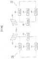
도 12는 본 발명의 일 실시예에 따른 상향링크 전송 타이밍을 설명하기 위한 도면이다.
도 13은 본 발명의 일 실시예에 따른 PUSCH 전송 타이밍을 설명하기 위한 도면이다.
도 14는 본 발명에 따른 기지국 장치 및 단말 장치의 구성을 도시한 도면이다.1 is a view for explaining a structure of a downlink radio frame.
2 is an exemplary diagram illustrating an example of a resource grid for one downlink slot.
3 is a diagram showing a structure of a downlink sub-frame.
4 is a diagram illustrating the structure of an uplink subframe.
5 and 6 are views for explaining a resource element group REG, which is a unit in which downlink control channels are allocated.
7 is a diagram showing a manner in which a physical control format indicator channel (PCFICH) is transmitted.
8 is a diagram illustrating the positions of a PCFICH and a physical HARQ indicator channel (PHICH).
9 is a diagram illustrating a location of a downlink resource element to which a PHICH group is mapped.
10 is a diagram for explaining a search space at each set level.
11 is a diagram for explaining uplink retransmission timing.
12 is a diagram illustrating uplink transmission timing according to an embodiment of the present invention.
13 is a diagram illustrating a PUSCH transmission timing according to an embodiment of the present invention.
14 is a diagram illustrating the configuration of a base station apparatus and a terminal apparatus according to the present invention.
이하의 실시예들은 본 발명의 구성요소들과 특징들을 소정 형태로 결합한 것들이다. 각 구성요소 또는 특징은 별도의 명시적 언급이 없는 한 선택적인 것으로 고려될 수 있다. 각 구성요소 또는 특징은 다른 구성요소나 특징과 결합되지 않은 형태로 실시될 수 있다. 또한, 일부 구성요소들 및/또는 특징들을 결합하여 본 발명의 실시예를 구성할 수도 있다. 본 발명의 실시예들에서 설명되는 동작들의 순서는 변경될 수 있다. 어느 실시예의 일부 구성이나 특징은 다른 실시예에 포함될 수 있고, 또는 다른 실시예의 대응하는 구성 또는 특징과 교체될 수 있다.The following embodiments are a combination of elements and features of the present invention in a predetermined form. Each component or characteristic may be considered optional unless otherwise expressly stated. Each component or feature may be implemented in a form that is not combined with other components or features. In addition, some of the elements and / or features may be combined to form an embodiment of the present invention. The order of the operations described in the embodiments of the present invention may be changed. Some configurations or features of certain embodiments may be included in other embodiments, or may be replaced with corresponding configurations or features of other embodiments.
본 명세서에서 본 발명의 실시예들을 기지국과 단말 간의 데이터 송신 및 수신의 관계를 중심으로 설명한다. 여기서, 기지국은 단말과 직접적으로 통신을 수행하는 네트워크의 종단 노드(terminal node)로서의 의미를 갖는다. 본 문서에서 기지국에 의해 수행되는 것으로 설명된 특정 동작은 경우에 따라서는 기지국의 상위 노드(upper node)에 의해 수행될 수도 있다.Embodiments of the present invention will be described herein with reference to the relationship between data transmission and reception between a base station and a terminal. Here, the BS has a meaning as a terminal node of a network that directly communicates with the MS. The particular operation described herein as performed by the base station may be performed by an upper node of the base station, as the case may be.
즉, 기지국을 포함하는 다수의 네트워크 노드들(network nodes)로 이루어지는 네트워크에서 단말과의 통신을 위해 수행되는 다양한 동작들은 기지국 또는 기지국 이외의 다른 네트워크 노드들에 의해 수행될 수 있음은 자명하다. '기지국(BS: Base Station)'은 고정국(fixed station), Node B, eNode B(eNB), 액세스 포인트(AP: Access Point) 등의 용어에 의해 대체될 수 있다. 릴레이는 Relay Node(RN), Relay Station(RS) 등의 용어에 의해 대체될 수 있다. 또한, '단말(Terminal)'은 UE(User Equipment), MS(Mobile Station), MSS(Mobile Subscriber Station), SS(Subscriber Station) 등의 용어로 대체될 수 있다.That is, it is apparent that various operations performed for communication with a terminal in a network composed of a plurality of network nodes including a base station can be performed by a network node other than the base station or the base station. A 'base station (BS)' may be replaced by a term such as a fixed station, a Node B, an eNode B (eNB), an access point (AP) Relays can be replaced by terms such as Relay Node (RN), Relay Station (RS), and so on. The term 'terminal' may be replaced with terms such as User Equipment (UE), Mobile Station (MS), Mobile Subscriber Station (MSS), and Subscriber Station (SS).
이하의 설명에서 사용되는 특정 용어들은 본 발명의 이해를 돕기 위해서 제공된 것이며, 이러한 특정 용어의 사용은 본 발명의 기술적 사상을 벗어나지 않는 범위에서 다른 형태로 변경될 수 있다.The specific terminology used in the following description is provided to aid understanding of the present invention, and the use of such specific terminology may be changed into other forms without departing from the technical idea of the present invention.
몇몇 경우, 본 발명의 개념이 모호해지는 것을 피하기 위하여 공지의 구조 및 장치는 생략되거나, 각 구조 및 장치의 핵심기능을 중심으로 한 블록도 형식으로 도시될 수 있다. 또한, 본 명세서 전체에서 동일한 구성요소에 대해서는 동일한 도면 부호를 사용하여 설명한다.In some instances, well-known structures and devices may be omitted or may be shown in block diagram form, centering on the core functionality of each structure and device, to avoid obscuring the concepts of the present invention. In the following description, the same components are denoted by the same reference numerals throughout the specification.
본 발명의 실시예들은 무선 접속 시스템들인 IEEE 802 시스템, 3GPP 시스템, 3GPP LTE 및 LTE-A(LTE-Advanced)시스템 및 3GPP2 시스템 중 적어도 하나에 개시된 표준 문서들에 의해 뒷받침될 수 있다. 즉, 본 발명의 실시예들 중 본 발명의 기술적 사상을 명확히 드러내기 위해 설명하지 않은 단계들 또는 부분들은 상기 문서들에 의해 뒷받침될 수 있다. 또한, 본 문서에서 개시하고 있는 모든 용어들은 상기 표준 문서에 의해 설명될 수 있다.Embodiments of the present invention may be supported by standard documents disclosed in at least one of the IEEE 802 systems, 3GPP systems, 3GPP LTE and LTE-Advanced (LTE-Advanced) systems, and 3GPP2 systems, which are wireless access systems. That is, the steps or portions of the embodiments of the present invention that are not described in order to clearly illustrate the technical idea of the present invention can be supported by the documents. In addition, all terms disclosed in this document may be described by the standard document.
이하의 기술은 CDMA(Code Division Multiple Access), FDMA(Frequency Division Multiple Access), TDMA(Time Division Multiple Access), OFDMA(Orthogonal Frequency Division Multiple Access), SC-FDMA(Single Carrier Frequency Division Multiple Access) 등과 같은 다양한 무선 접속 시스템에 사용될 수 있다. CDMA는 UTRA(Universal Terrestrial Radio Access)나 CDMA2000과 같은 무선 기술(radio technology)로 구현될 수 있다. TDMA는 GSM(Global System for Mobile communications)/GPRS(General Packet Radio Service)/EDGE(Enhanced Data Rates for GSM Evolution)와 같은 무선 기술로 구현될 수 있다. OFDMA는 IEEE 802.11 (Wi-Fi), IEEE 802.16 (WiMAX), IEEE 802-20, E-UTRA(Evolved UTRA) 등과 같은 무선 기술로 구현될 수 있다. UTRA는 UMTS(Universal Mobile Telecommunications System)의 일부이다. 3GPP(3rd Generation Partnership Project) LTE(long term evolution)는 E-UTRA를 사용하는 E-UMTS(Evolved UMTS)의 일부로써, 하향링크에서 OFDMA를 채용하고 상향링크에서 SC-FDMA를 채용한다. LTE-A(Advanced)는 3GPP LTE의 진화이다. WiMAX는 IEEE 802.16e 규격(WirelessMAN-OFDMA Reference System) 및 발전된 IEEE 802.16m 규격(WirelessMAN-OFDMA Advanced system)에 의하여 설명될 수 있다. 명확성을 위하여 이하에서는 3GPP LTE 및 3GPP LTE-A 시스템을 위주로 설명하지만 본 발명의 기술적 사상이 이에 제한되는 것은 아니다.The following description will be made on the assumption that the present invention is applicable to a CDMA system such as Code Division Multiple Access (CDMA), Frequency Division Multiple Access (FDMA), Time Division Multiple Access (TDMA), Orthogonal Frequency Division Multiple Access (OFDMA), and Single Carrier Frequency Division Multiple Access And can be used in various wireless access systems. CDMA may be implemented in radio technology such as Universal Terrestrial Radio Access (UTRA) or CDMA2000. The TDMA may be implemented in a wireless technology such as Global System for Mobile communications (GSM) / General Packet Radio Service (GPRS) / Enhanced Data Rates for GSM Evolution (EDGE). OFDMA may be implemented in wireless technologies such as IEEE 802.11 (Wi-Fi), IEEE 802.16 (WiMAX), IEEE 802-20, and Evolved UTRA (E-UTRA). UTRA is part of the Universal Mobile Telecommunications System (UMTS). 3GPP (3rd Generation Partnership Project) LTE (Long Term Evolution) is a part of E-UMTS (Evolved UMTS) using E-UTRA, adopting OFDMA in downlink and SC-FDMA in uplink. LTE-A (Advanced) is the evolution of 3GPP LTE. WiMAX can be described by the IEEE 802.16e standard (WirelessMAN-OFDMA Reference System) and the advanced IEEE 802.16m standard (WirelessMAN-OFDMA Advanced system). For the sake of clarity, the 3GPP LTE and 3GPP LTE-A systems will be described below, but the technical idea of the present invention is not limited thereto.
도 1은 3GPP LTE 시스템에서 사용되는 무선 프레임의 구조를 나타내는 도면이다. 도 1(a)를 참조하면 하나의 무선 프레임은 10 개의 서브프레임을 포함하고, 하나의 서브프레임은 시간 영역에서 2 개의 슬롯을 포함한다. 하나의 서브프레임을 전송하는 시간은 전송시간간격(Transmission Time Interval; TTI)으로 정의된다. 예를 들어, 하나의 서브프레임은 1ms의 길이를 가질 수 있고, 하나의 슬롯은 0.5ms의 길이를 가질 수 있다. 하나의 슬롯은 시간 영역에서 복수개의 OFDM 심볼들을 포함할 수 있다. 3GPP LTE 시스템은 하향링크에서 OFDMA 방식을 이용하므로, 상기 OFDM 심볼은 하나의 심볼 길이(period)를 나타낸다. 하나의 심볼은 상향링크에서 SC-FDMA 심볼 또는 심볼 길이로 칭하여질 수 있다. 자원블록(Resource Block; RB)은 자원 할당 단위로서, 하나의 슬롯에서 복수개의 연속하는 부반송파를 포함한다. 위와 같은 무선 프레임의 구조는 단지 예시적인 것이다. 따라서, 하나의 무선 프레임에 포함되는 서브프레임의 개수, 하나의 서브프레임에 포함되는 슬롯의 개수, 또는 하나의 슬롯에 포함되는 OFDM 심볼의 개수는 다양한 방식으로 변경될 수도 있다.1 is a diagram illustrating a structure of a radio frame used in a 3GPP LTE system. Referring to FIG. 1 (a), one radio frame includes 10 subframes, and one subframe includes two slots in the time domain. The transmission time of one subframe is defined as a transmission time interval (TTI). For example, one subframe may have a length of 1 ms, and one slot may have a length of 0.5 ms. One slot may comprise a plurality of OFDM symbols in the time domain. Since the 3GPP LTE system uses the OFDMA scheme in the downlink, the OFDM symbol represents one symbol period. One symbol may be referred to as an SC-FDMA symbol or a symbol length in the uplink. A resource block (RB) is a resource allocation unit, and includes a plurality of consecutive subcarriers in one slot. The structure of such a radio frame is merely exemplary. Therefore, the number of subframes included in one radio frame, the number of slots included in one subframe, or the number of OFDM symbols included in one slot may be changed in various manners.
도 1(b)는 타입 2 무선 프레임의 구조를 예시한다. 타입 2 무선 프레임은 2개의 하프 프레임(half frame)으로 구성된다. 각 하프 프레임은 5개의 서브프레임과 DwPTS(Downlink Pilot Time Slot), 보호구간(Guard Period, GP), UpPTS(Uplink Pilot Time Slot)로 구성되며, 이 중 1개의 서브프레임은 2개의 슬롯으로 구성된다. DwPTS는 단말에서의 초기 셀 탐색, 동기화 또는 채널 추정에 사용된다. UpPTS는 기지국에서의 채널 추정과 단말의 상향링크 전송 동기를 맞추는 데 사용된다. 보호구간은 상향링크와 하향링크 사이에 하향링크 신호의 다중경로 지연으로 인해 상향링크에서 생기는 간섭을 제거하기 위한 구간이다.Fig. 1 (b) illustrates the structure of a
여기서 무선 프레임의 구조는 예시에 불과하고, 무선 프레임에 포함되는 서브프레임의 수 또는 서브프레임에 포함되는 슬롯의 수, 슬롯에 포함되는 심볼의 수는 다양하게 변경될 수 있다.Here, the structure of the radio frame is merely an example, and the number of subframes included in a radio frame, the number of slots included in a subframe, and the number of symbols included in a slot can be variously changed.
도 2는 하향링크 슬롯에서의 자원 그리드(resource grid)를 나타내는 도면이다. 하나의 하향링크 슬롯은 시간 영역에서 7 개의 OFDM 심볼을 포함하고, 하나의 자원블록(RB)은 주파수 영역에서 12 개의 부반송파를 포함하는 것으로 도시되어 있지만, 본 발명이 이에 제한되는 것은 아니다. 예를 들어, 일반 CP(Cyclic Prefix)의 경우에는 하나의 슬롯이 7 OFDM 심볼을 포함하지만, 확장된 CP(extended-CP)의 경우에는 하나의 슬롯이 6 OFDM 심볼을 포함할 수 있다. 자원 그리드 상의 각각의 요소는 자원 요소(resource element)라 한다. 하나의 자원블록은 12×7 자원 요소를 포함한다. 하향링크 슬롯에 포함되는 자원블록들의 NDL의 개수는 하향링크 전송 대역폭에 따른다. 상향링크 슬롯의 구조는 하향링크 슬롯의 구조와 동일할 수 있다.2 is a diagram illustrating a resource grid in a downlink slot. One downlink slot includes seven OFDM symbols in the time domain and one resource block (RB) is shown to include 12 subcarriers in the frequency domain, but the present invention is not limited thereto. For example, one slot includes 7 OFDM symbols in the case of a general cyclic prefix (CP), but one slot may include 6 OFDM symbols in the case of an extended-CP (CP). Each element on the resource grid is called a resource element. One resource block includes 12 × 7 resource elements. The number of NDLs of resource blocks included in a downlink slot depends on a downlink transmission bandwidth. The structure of the uplink slot may be the same as the structure of the downlink slot.
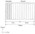
도 3은 하향링크 서브프레임의 구조를 나타내는 도면이다. 하나의 서브프레임 내에서 첫 번째 슬롯의 앞 부분의 최대 3 개의 OFDM 심볼은 제어 채널이 할당되는 제어 영역에 해당한다. 나머지 OFDM 심볼들은 물리하향링크공유채널(Physical Downlink Shared Chancel; PDSCH)이 할당되는 데이터 영역에 해당한다. 3GPP LTE 시스템에서 사용되는 하향링크 제어 채널들에는, 예를 들어, 물리제어포맷지시자채널(Physical Control Format Indicator Channel; PCFICH), 물리하향링크제어채널(Physical Downlink Control Channel; PDCCH), 물리HARQ지시자채널(Physical Hybrid automatic repeat request Indicator Channel; PHICH) 등이 있다.3 is a diagram showing a structure of a downlink sub-frame. In a subframe, a maximum of three OFDM symbols in the first part of the first slot corresponds to a control area to which a control channel is allocated. The remaining OFDM symbols correspond to a data area to which a Physical Downlink Shared Chanel (PDSCH) is allocated. The downlink control channels used in the 3GPP LTE system include, for example, a physical control format indicator channel (PCFICH), a physical downlink control channel (PDCCH), a physical HARQ indicator channel (Physical Hybrid Automatic Repeat Request Indicator Channel (PHICH)).
PCFICH는 서브프레임의 첫 번째 OFDM 심볼에서 전송되고 서브프레임 내의 제어 채널 전송에 사용되는 OFDM 심볼의 개수에 대한 정보를 포함한다.The PCFICH includes information on the number of OFDM symbols transmitted in the first OFDM symbol of the subframe and used for control channel transmission in the subframe.
PHICH는 상향링크 전송의 응답으로서 HARQ ACK/NACK 신호를 포함한다.The PHICH includes an HARQ ACK / NACK signal as a response to the uplink transmission.
PDCCH를 통하여 전송되는 제어 정보를 하향링크제어정보(Downlink Control Information; DCI)라 한다. DCI는 상향링크 또는 하향링크 스케줄링 정보를 포함하거나 임의의 단말 그룹에 대한 상향링크 전송 전력 제어 명령을 포함한다. PDCCH는 하향링크공유채널(DL-SCH)의 자원 할당 및 전송 포맷, 상향링크공유채널(UL-SCH)의 자원 할당 정보, 페이징채널(PCH)의 페이징 정보, DL-SCH 상의 시스템 정보, PDSCH 상으로 전송되는 임의접속응답(Random Access Response)과 같은 상위계층 제어 메시지의 자원 할당, 임의의 단말 그룹 내의 개별 단말에 대한 전송 전력 제어 명령의 세트, 전송 전력 제어 정보, VoIP(Voice over IP)의 활성화 등을 포함할 수 있다. 복수의 PDCCH가 제어 영역 내에서 전송될 수 있다. 단말은 복수의 PDCCH를 모니터링할 수 있다. PDCCH는 하나 이상의 연속하는 제어채널요소(Control Channel Element; CCE)의 조합(aggregation)으로 전송된다. CCE는 무선 채널의 상태에 기초한 코딩 레이트로 PDCCH를 제공하기 위해 사용되는 논리 할당 단위이다. CCE는 복수개의 자원 요소 그룹에 대응한다. PDCCH의 포맷과 이용가능한 비트 수는 CCE의 개수와 CCE에 의해 제공되는 코딩 레이트 간의 상관관계에 따라서 결정된다. 기지국은 단말에게 전송되는 DCI에 따라서 PDCCH 포맷을 결정하고, 제어 정보에 순환잉여검사(Cyclic Redundancy Check; CRC)를 부가한다. CRC는 PDCCH의 소유자 또는 용도에 따라 무선 네트워크 임시 식별자(Radio Network Temporary Identifier; RNTI)라 하는 식별자로 마스킹된다. PDCCH가 특정 단말에 대한 것이면, 단말의 cell-RNTI(C-RNTI) 식별자가 CRC에 마스킹될 수 있다. 또는, PDCCH가 페이징 메시지에 대한 것이면, 페이징 지시자 식별자(Paging Indicator Identifier; P-RNTI)가 CRC에 마스킹될 수 있다. PDCCH가 시스템 정보(보다 구체적으로, 시스템 정보 블록(SIB))에 대한 것이면, 시스템 정보 식별자 및 시스템 정보 RNTI(SI-RNTI)가 CRC에 마스킹될 수 있다. 단말의 임의 접속 프리앰블의 전송에 대한 응답인 임의접속응답을 나타내기 위해, 임의접속-RNTI(RA-RNTI)가 CRC에 마스킹될 수 있다.The control information transmitted through the PDCCH is referred to as downlink control information (DCI). The DCI includes uplink or downlink scheduling information or includes an uplink transmission power control command for an arbitrary terminal group. The PDCCH includes a resource allocation and transmission format of a downlink shared channel (DL-SCH), resource allocation information of an uplink shared channel (UL-SCH), paging information of a paging channel (PCH), system information on a DL- A set of transmission power control commands for individual terminals in an arbitrary terminal group, transmission power control information, activation of VoIP (Voice over IP), resource allocation of upper layer control messages such as random access response And the like. A plurality of PDCCHs may be transmitted within the control domain. The UE can monitor a plurality of PDCCHs. The PDCCH is transmitted in an aggregation of one or more contiguous Control Channel Elements (CCEs). The CCE is a logical allocation unit used to provide the PDCCH with a coding rate based on the state of the wireless channel. The CCE corresponds to a plurality of resource element groups. The format of the PDCCH and the number of available bits are determined according to the correlation between the number of CCEs and the coding rate provided by the CCE. The base station determines the PDCCH format according to the DCI transmitted to the UE and adds a cyclic redundancy check (CRC) to the control information. The CRC is masked with an identifier called a Radio Network Temporary Identifier (RNTI) according to the owner or use of the PDCCH. If the PDCCH is for a particular UE, the cell-RNTI (C-RNTI) identifier of the UE may be masked in the CRC. Alternatively, if the PDCCH is for a paging message, a Paging Indicator Identifier (P-RNTI) may be masked in the CRC. If the PDCCH is for system information (more specifically, the System Information Block (SIB)), the system information identifier and the system information RNTI (SI-RNTI) may be masked to the CRC. A random access-RNTI (RA-RNTI) may be masked to the CRC to indicate a random access response that is a response to the transmission of the UE's random access preamble.
도 4는 상향링크 서브프레임의 구조를 나타내는 도면이다. 상향링크 서브프레임은 주파수 영역에서 제어 영역과 데이터 영역으로 분할될 수 있다. 제어 영역에는 상향링크 제어 정보를 포함하는 물리상향링크제어채널(Physical Uplink Control Channel; PUCCH)이 할당된다. 데이터 영역에는 사용자 데이터를 포함하는 물리상향링크공유채널(Physical uplink shared channel; PUSCH)이 할당된다. 단일 반송파 특성을 유지하기 위해서, 하나의 단말은 PUCCH와 PUSCH를 동시에 전송하지 않는다. 하나의 단말에 대한 PUCCH는 서브프레임에서 자원블록 쌍(RB pair)에 할당된다. 자원블록 쌍에 속하는 자원블록들은 2 슬롯에 대하여 상이한 부반송파를 차지한다. 이를 PUCCH에 할당되는 자원블록 쌍이 슬롯 경계에서 주파수-호핑(frequency-hopped)된다고 한다.4 is a diagram illustrating the structure of an uplink subframe. The UL subframe may be divided into a control region and a data region in the frequency domain. A physical uplink control channel (PUCCH) including uplink control information is allocated to the control region. A physical uplink shared channel (PUSCH) including user data is allocated to the data area. To maintain a single carrier characteristic, one terminal does not transmit PUCCH and PUSCH at the same time. A PUCCH for one terminal is allocated to a resource block pair (RB pair) in a subframe. Resource blocks belonging to a resource block pair occupy different subcarriers for two slots. It is assumed that the resource block pair allocated to the PUCCH is frequency-hopped at the slot boundary.
DCIDCI 포맷 format
현재 LTE-A(release 10)에 의하면 DCI 포맷 0, 1, 1A, 1B, 1C, 1D, 2, 2A, 2B, 2C, 3, 3A, 4 가 정의되어 있다. 여기서 DCI 포맷 0, 1A, 3, 3A는, 후술할 블라인드 복호 횟수를 줄이기 위해 동일한 메시지 크기를 갖도록 규정되어 있다. 이러한 DCI 포맷들은 전송하려는 제어정보의 용도에 따라 i)상향링크 승인에 사용되는 DCI 포맷 0, 4, ii)하향링크 스케줄링 할당에 사용되는 DCI 포맷 1, 1A, 1B, 1C, 1D, 2, 2A, 2B, 2C, iii)전력제어 명령을 위한 DCI 포맷 3, 3A로 구분할 수 있다.According to LTE-A (release 10), DCI formats 0, 1, 1A, 1B, 1C, 1D, 2, 2A, 2B, 2C, 3, 3A and 4 are defined. Here, DCI formats 0, 1A, 3, and 3A are defined to have the same message size in order to reduce the number of blind decryption to be described later. These DCI formats may be: i) DCI formats 0, 4, ii) DCI formats 1, 1A, 1B, 1C, 1D, 2, 2A used for downlink scheduling assignment, depending on the purpose of the control information to be transmitted. , 2B, 2C, and iii) DCI formats 3 and 3A for power control commands.
상향링크 승인에 사용되는 DCI 포맷 0의 경우, 후술할 반송파 병합에 관련하여 필요한 반송파 오프셋(carrier indicator), DCI 포맷 0과 1A를 구분하는데 사용되는 오프셋(flag for format 0/format 1A differentiation), 상향링크 PUSCH 전송에서 주파수 호핑이 사용되는지 여부를 알려주는 호핑 플래그(frequency hopping flag), 단말이 PUSCH 전송에 사용해야 할 자원블록 할당에 대한 정보(resource block assignment), 변조 및 부호화 방식(modulation and coding scheme), HARQ 프로세스와 관련해 초기전송을 위해 버퍼를 비우는데 사용되는 새 데이터 지시자(new data indicator), PUSCH를 위한 전송전력 제어명령(TPC command for scheduled for PUSCH), DMRS(Demodulation reference signal)를 위한 순환이동 정보(cyclic shift for DM RS and OCC index), TDD 동작에서 필요한 상향링크 인덱스(UL index) 및 채널품질정보(Channel Quality Indicator) 요구 정보(CSI request) 등을 포함할 수 있다. 한편, DCI 포맷 0의 경우 동기식 HARQ를 사용하므로 하향링크 스케줄링 할당에 관련된 DCI 포맷들처럼 리던던시 버전(redundancy version)을 포함하지 않는다. 반송파 오프셋의 경우, 크로스 반송파 스케줄링이 사용되지 않는 경우에는 DCI 포맷에 포함되지 않는다.In the case of
DCI 포맷 4는 LTE-A 릴리즈 10에서 새로이 추가된 것으로서 LTE-A에서 상향링크 전송에 공간 다중화가 적용되는 것을 지원하기 위한 것이다. DCI 포맷 4의 경우 DCI 포맷 0과 비교하여 공간 다중화를 위한 정보들을 더 포함하므로 더 큰 메시지 크기를 가지며, DCI 포맷 0에 포함되는 제어정보에 추가적인 제어정보를 더 포함한다. 즉, DCI 포맷 4의 경우, 두 번째 전송블록을 위한 변조 및 부호화 방식, 다중 안테나 전송을 위한 프리코딩 정보, 사운딩참조신호 요청(SRS request) 정보를 더 포함한다. 한편, DCI 포맷 4는 DCI 포맷 0보다 큰 크기를 가지므로 DCI 포맷 0과 1A를 구분하는 오프셋은 포함하지 않는다.
하향링크 스케줄링 할당에 관련된 DCI 포맷 1, 1A, 1B, 1C, 1D, 2, 2A, 2B, 2C는 크게 공간 다중화를 지원하지 않는 1, 1A, 1B, 1C, 1D 와 공간 다중화를 지원하는 2, 2A, 2B, 2C 로 구분될 수 있다.DCI formats 1, 1A, 1B, 1C, 1D, 2, 2A, 2B and 2C related to downlink scheduling assignment are divided into 1, 1A, 1B, 1C and 1D, which do not support spatial multiplexing, 2A, 2B, and 2C.
DCI 포맷 1C는 컴팩트 하향링크 할당으로서 주파수 연속적 할당만을 지원하며, 다른 포맷들과 비교해 반송파 오프셋, 리던던시 버전을 포함하지 않는다.DCI format 1C only supports frequency sequential assignment as a compact downlink assignment, and does not include carrier offset, redundancy versions compared to other formats.
DCI 포맷 1A는 하향링크 스케줄링 및 랜덤 액세스 절차를 위한 포맷이다. 여기에는 반송파 오프셋, 하향링크 분산형 전송이 사용되는지 여부를 알려주는 표시자, PDSCH 자원 할당 정보, 변조 및 부호화 방식, 리던던시 버전, 소프트 컴바이닝을 위해 사용되는 프로세서를 알려주기 위한 HARQ 프로세서 번호, HARQ 프로세스와 관련해 초기전송을 위해 버퍼를 비우는데 사용되는 새 데이터 오프셋, PUCCH를 위한 전송전력 제어명령, TDD 동작에서 필요한 상향링크 인덱스 등을 포함할 수 있다.DCI format 1A is a format for downlink scheduling and random access procedures. An HARQ processor number for informing a processor used for soft combining, a HARQ processor number for informing a processor used for soft combining, a HARQ processor number for informing a processor used for soft combining, A new data offset used to empty the buffer for initial transmission in relation to the process, a transmit power control command for the PUCCH, an uplink index required for TDD operation, and the like.
DCI 포맷 1의 경우 대부분의 제어정보가 DCI 포맷 1A과 유사하다. 다만, DCI 포맷 1A가 연속적인 자원 할당에 관련된 것과 비교해, DCI 포맷 1은 비연속적 자원 할당을 지원한다. 따라서 DCI 포맷 1은 자원할당 헤더를 더 포함하므로 자원할당의 유연성이 증가하는 것의 트레이드 오프로서 제어 시그널링 오버헤드는 다소 증가한다.For
DCI 포맷 1B, 1D의 경우에는 DCI 포맷 1과 비교해 프리코딩 정보를 더 포함하는 점에서 공통된다. DCI 포맷 1B는 PMI 확인을, DCI 포맷 1D는 하향링크 전력 오프셋 정보를 각각 포함한다. 그 외 DCI 포맷 1B, 1D에 포함된 제어정보는 DCI 포맷 1A의 경우와 대부분 일치한다.In the case of DCI formats 1B and 1D, they are common in that they further include precoding information as compared with
DCI 포맷 2, 2A, 2B, 2C는 기본적으로 DCI 포맷 1A에 포함된 제어정보들을 대부분 포함하면서, 공간 다중화를 위한 정보들을 더 포함한다. 여기에는 두 번째 전송 블록에 관한 변조 및 부호화 방식, 새 데이터 오프셋 및 리던던시 버전이 해당된다.The DCI formats 2, 2A, 2B, and 2C basically include most of the control information included in the DCI format 1A, and further include information for spatial multiplexing. This includes modulation and coding schemes, new data offsets and redundancy versions for the second transport block.
DCI 포맷 2는 폐루프 공간 다중화를 지원하며, 2A는 개루프 공간 다중화를 지원한다. 양자 모두 프리코딩 정보를 포함한다. DCI 포맷 2B는 빔 포밍과 결합된 듀얼 레이어 공간 다중화를 지원하며 DMRS를 위한 순환이동 정보를 더 포함한다. DCI 포맷 2C는 DCI 포맷 2B의 확장으로 이해될 수 있으며 여덟개의 레이어까지 공공간 다중화를 지원한다.
DCI 포맷 3, 3A는 전술한 상향링크 승인 및 하향링크 스케줄링 할당을 위한 DCI 포맷들에 포함되어 있는 전송전력 제어 정보를 보완, 즉 반-지속적(semi-persistent) 스케줄링을 지원하기 위해 사용될 수 있다. DCI 포맷 3의 경우 단말당 1bit, 3A의 경우 2bit의 명령이 사용된다.The DCI formats 3 and 3A may be used to supplement the transmission power control information included in the DCI formats for the uplink grant and the downlink scheduling assignment described above, i.e., to support semi-persistent scheduling. In case of
상술한 바와 같은 DCI 포맷 중 어느 하나는 하나의 PDCCH를 통해 전송되며, 복수의 PDCCH가 제어 영역 내에서 전송될 수 있다. 단말은 복수의 PDCCH를 모니터링 할 수 있다.Any one of the DCI formats as described above is transmitted on one PDCCH, and a plurality of PDCCHs can be transmitted in the control domain. The UE can monitor a plurality of PDCCHs.
하향링크 제어채널의 구성Configuration of downlink control channel
하향링크 제어채널이 전송되는 영역으로 기본적으로는 각각의 서브프레임의 처음 3개의 OFDM 심볼이 사용될 수 있으며, 하향링크 제어채널의 오버헤드에 따라서 1 내지 3개의 OFDM 심볼이 사용될 수 있다. 하향링크 제어채널을 위한 OFDM 심볼의 개수를 각 서브프레임마다 조정하기 위하여, PCFICH가 사용될 수 있다. 상향링크 전송에 대한 확인응답(긍정확인응답(ACK)/부정확인응답(NACK))을 하향링크를 통하여 제공하기 위하여 PHICH가 사용될 수 있다. 또한, 하향링크 데이터전송 또는 상향링크의 데이터전송을 위한 제어정보의 전송을 위해서 PDCCH가 사용될 수 있다.The first three OFDM symbols of each subframe may be used as the transmission area of the downlink control channel, and one to three OFDM symbols may be used according to the overhead of the downlink control channel. In order to adjust the number of OFDM symbols for the downlink control channel for each subframe, a PCFICH may be used. The PHICH may be used to provide an acknowledgment (positive acknowledgment (ACK) / negative acknowledgment (NACK)) for the uplink transmission on the downlink. In addition, a PDCCH can be used for transmission of control information for downlink data transmission or uplink data transmission.
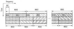
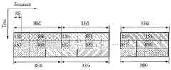
도 5 및 도 6 은 위와 같은 하향링크 제어채널들이 각각의 서브프레임의 제어 영역에서 자원요소그룹(Resource Element Group; REG) 단위로 할당되는 것을 나타낸다. 도 5 은 1 개 또는 2 개의 전송 안테나 구성을 가지는 시스템에 대한 것이고, 도 6 은 4 개의 전송 안테나 구성을 가지는 시스템에 대한 것이다. 도 5 및 도 6 에서 도시하는 바와 같이, 제어채널이 할당되는 기본적인 자원단위인 REG 는, 참조신호가 할당되는 자원요소를 제외하고 주파수 영역에서 연접한 4개의 RE 로 구성된다. 하향링크 제어채널의 오버헤드에 따라서 특정 개수의 REG 가 하향링크 제어채널의 전송에 이용될 수 있다.5 and 6 show that the DL control channels are allocated in units of Resource Element Groups (REG) in the control regions of the respective subframes. FIG. 5 is for a system with one or two transmit antenna configurations, and FIG. 6 is for a system with four transmit antenna configurations. As shown in FIGS. 5 and 6, the REG, which is a basic resource unit to which the control channel is allocated, is composed of four REs concatenated in the frequency domain except for the resource element to which the reference signal is allocated. Depending on the overhead of the downlink control channel, a certain number of REGs may be used for transmission of the downlink control channel.
PCFICHPCFICH ( (PhysicalPhysicalControlControlFormatFormatIndicatorIndicatorChannelChannel))
각각의 모든 서브프레임마다 해당 서브프레임의 자원 할당 정보 등을 제공하기 위해서 PDCCH 가 OFDM 심볼 인덱스 0 내지 2 사이에서 전송될 수 있고, 제어채널의 오버헤드에 따라서 OFDM 심볼 인덱스 0 이 사용되거나, OFDM 심볼 인덱스 0 및 1이 사용되거나, OFDM 심볼 인덱스 0 내지 2 가 사용될 수 있다. 이와 같이 제어채널이 사용하는 OFDM 심볼의 개수를 서브프레임마다 변경 할 수 있는데, 이에 대한 정보는 PCFICH를 통해 제공될 수 있다. 따라서, PCFICH는 각각의 모든 서브프레임에서 전송되어야 한다.A PDCCH may be transmitted between
PCFICH를 통해 3가지의 정보가 제공될 수 있다. 아래의 표 1 은 PCFICH의 CFI(Control Format Indicator)를 나타낸다. CFI=1 은 OFDM 심볼 인덱스 0 에서 PDCCH가 전송됨을 나타내고, CFI=2 는 OFDM 심볼 인덱스 0 및 1 에서 PDCCH가 전송됨을 나타내고, CFI=3 은 OFDM 심볼 인덱스 0 내지 2 에서 PDCCH가 전송됨을 나타낸다.Three kinds of information can be provided through PCFICH. Table 1 below shows CFI (Control Format Indicator) of PCFICH. CFI = 1 indicates that the PDCCH is transmitted at the

PCFICH 를 통해 전송되는 정보는 시스템 대역폭(system bandwidth)에 따라 다르게 정의될 수 있다. 예를 들면, 시스템의 대역폭이 특정 임계치보다 작은 경우 CFI=1, 2, 3 은 각각 2, 3, 4 개의 OFDM 심볼이 PDCCH를 위해 사용됨을 나타낼 수도 있다.Information transmitted through the PCFICH may be defined differently depending on the system bandwidth. For example, if the bandwidth of the system is below a certain threshold, CFI = 1, 2, 3 may indicate that 2, 3, or 4 OFDM symbols are used for the PDCCH, respectively.
도 7 은 PCFICH가 전송되는 방식을 나타내는 도면이다. 도 7 에서 도시하는 REG 는, 4개의 부반송파로 구성되어 있고, RS(참조신호)를 제외한 데이터 부반송파로만 구성되어 있으며, 일반적으로 전송 다이버시티(transmit diversity) 기법이 적용될 수 있다. 또한 REG의 위치는, 셀간에 간섭을 주지 않도록 셀마다 (즉, 셀 식별자에 따라서) 주파수 시프트될 수 있다. 추가적으로, PCFICH는 항상 서브프레임의 첫 번째 OFDM 심볼(OFDM 심볼 인덱스 0)에서 전송된다. 이에 따라 수신단에서는 서브프레임을 수신할 때에 먼저 PCFICH의 정보를 확인하여 PDCCH 가 전송되는 OFDM 심볼의 개수를 파악하고 그에 따라서 PDCCH를 통해 전송되는 제어 정보를 수신할 수 있다.7 is a diagram showing a manner in which the PCFICH is transmitted. The REG shown in FIG. 7 is composed of four subcarriers, and is composed only of data subcarriers except RS (reference signal), and a transmit diversity technique can be generally applied. Also, the position of the REG may be frequency-shifted per cell (i.e., depending on the cell identifier) so as not to interfere with the cells. In addition, the PCFICH is always transmitted in the first OFDM symbol (OFDM symbol index 0) of the subframe. Accordingly, the receiver can check the information of the PCFICH to receive the control information transmitted through the PDCCH according to the number of the OFDM symbols to which the PDCCH is transmitted.
PHICHPHICH ( (PhysicalPhysicalHybridHybrid--ARQARQIndicatorIndicatorChannelChannel))
도 8 은 특정 대역폭에서 일반적으로 적용되는 PCFICH 및 PHICH 채널의 위치를 나타내는 도면이다. PHICH 를 통해서 상향링크 데이터 전송에 대한 ACK/NACK 정보가 전송된다. 하나의 서브프레임에서 여러 개의 PHICH 그룹이 만들어지고, 하나의 PHICH 그룹에는 여러 개의 PHICH가 존재한다. 따라서, 하나의 PHICH 그룹에는 여러 개의 단말에 대한 PHICH 채널이 포함된다.8 is a diagram showing locations of PCFICH and PHICH channels generally applied in a specific bandwidth. ACK / NACK information for uplink data transmission is transmitted through the PHICH. A plurality of PHICH groups are created in one subframe, and a plurality of PHICHs are present in one PHICH group. Therefore, one PHICH group includes PHICH channels for a plurality of terminals.
도 8 에서 도시하는 바와 같이, 여러 개의 PHICH 그룹에서 각 단말기에 대한 PHICH 할당은, PUSCH 자원 할당(resource allocation)의 가장 낮은 물리자원블록(Physical Resource Block; PRB) 인덱스(lowest PRB index)와, 상향링크 승인(grant) PDCCH 를 통해 전송되는 복조참조신호(Demodulation RS; DMRS)를 위한 순환시프트(Cyclic Shift) 인덱스를 이용하여 이루어진다. DMRS 는 상향링크 참조신호이며, 상향링크 데이터의 복조를 위한 채널 추정을 위해서 상향링크 전송과 함께 제공되는 신호이다. 또한, PHICH 자원은 (


상기 수학식 1 에서nDMRS 는 PHICH 가 연관된 상향링크 전송에서 사용된 DMRS 에 적용되는 순환시프트이며, 해당 PUSCH 전송과 연관된 전송블록(TB)에 대한 가장 최근의 상향링크 승인 제어 정보(예를 들어, DCI 포맷 0 또는 4)의 'cyclic shift for DMRS' 필드의 값에 매핑된다. 예를 들어, 가장 최근의 상향링크 승인 DCI 포맷의 'cyclic shift for DMRS' 필드는 3 비트 크기를 가질 수 있고, 이 필드가 '000'값을 가지면nDMRS 는 '0' 값을 가지도록 설정될 수 있다.In
상기 수학식 1 에서


상기 수학식 2 에서Ng 는 물리방송채널(Physical Broadcast Channel; PBCH)로 전송되는 PHICH 자원의 양에 대한 정보이며,Ng 는 2 비트 크기를 가지고 (Ng∈ {1/6,1/2,1,2})으로 표현된다. 상기 수학식 2 에서
또한, 기존의 3GPP LTE 릴리즈-8/9 에서 정의되는 직교 시퀀스의 예는 아래의 표 2 와 같다.An example of the orthogonal sequence defined in the existing 3GPP LTE Release-8/9 is shown in Table 2 below.

도 9 는 PHICH 그룹이 매핑되는 하향링크 자원요소 위치를 나타내는 도면이다. PHICH 그룹은 PHICH 구간(duration)에 따라서 도 9 와 같이 하나의 서브프레임 내에서 상이한 시간 영역 (즉, 상이한 OS(OFDM Symbol)) 상에서 구성될 수도 있다.9 is a diagram illustrating a location of a downlink resource element to which a PHICH group is mapped. The PHICH group may be configured in different time domains (i.e., different OFDM symbols) within one subframe as shown in FIG. 9 depending on the PHICH duration.
PDCCHPDCCH 프로세싱 Processing
PDCCH를 RE들에 매핑할 때 연속된 논리할당단위인 제어채널요소(CCE)가 사용된다. 하나의 CCE는 복수(예를 들어, 9개)의 자원요소그룹(REG)을 포함하고, 하나의 REG는 참조 신호(RS)를 제외한 상태에서 이웃하는 네 개의 RE로 구성된다.When mapping the PDCCH to the REs, a control channel element (CCE) which is a consecutive logical allocation unit is used. One CCE includes a plurality of (e.g., nine) resource element groups (REG), and one REG is composed of four neighboring REs excluding the reference signal RS.
특정한 PDCCH를 위해 필요한 CCE의 개수는 제어정보의 크기인 DCI 페이로드, 셀 대역폭, 채널 부호화율 등에 따라 달라진다. 구체적으로 특정한 PDCCH를 위한 CCE의 개수는 다음 표 3과 같이 PDCCH 포맷에 따라 정의될 수 있다.The number of CCEs required for a particular PDCCH depends on the DCI payload, the cell bandwidth, the channel coding rate, etc., which is the size of the control information. Specifically, the number of CCEs for a specific PDCCH can be defined according to the PDCCH format as shown in Table 3 below.

PDCCH는 앞서 설명된 바와 같이 네가지 포맷 중 어느 하나의 포맷이 사용될 수 있는데, 이는 단말에게 알려지지 않는다. 따라서 단말의 입장에서는 PDCCH 포맷을 알지 못한 채 복호를 하여야 하는데, 이를 블라인드 복호라 한다. 다만, 단말이 하향링크에 사용되는 가능한 모든 CCE를 각 PDCCH 포맷에 대하여 복호하는 것은 큰 부담이 되므로, 스케줄러에 대한 제약과 복호 시도 횟수를 고려하여 탐색공간(Search Space)이 정의된다.The PDCCH can use any one of the four formats as described above, which is unknown to the UE. Therefore, the UE must decode the PDCCH without knowing the PDCCH format. This is called blind decoding. However, it is a great burden to the UE to decode all possible CCEs used in the downlink for each PDCCH format. Therefore, a search space is defined in consideration of the constraints on the scheduler and the number of decoding attempts.
즉, 탐색공간은 집합레벨(Aggregation Level) 상에서 단말이 복호를 시도해야 하는 CCE들로 이루어진 후보 PDCCH의 집합이다. 여기서 집합레벨 및 PDCCH 후보의 수는 다음 표 4와 같이 정의될 수 있다.That is, the search space is a set of candidate PDCCHs, which are composed of CCEs to which the UE should attempt to decode at an aggregation level. Here, the aggregation level and the number of PDCCH candidates can be defined as shown in Table 4 below.

상기 표 4에서 알 수 있듯이 4가지의 집합레벨이 존재하므로, 단말은 각 집합레벨에 따라 복수개의 탐색공간을 갖게 된다. 또한, 표 4에서 나타내는 바와 같이 탐색공간은 단말 특정 탐색공간과 공통 탐색공간으로 구분될 수 있다. 단말 특정 탐색공간은 특정한 단말들을 위한 것으로서 각 단말은 단말 특정 탐색공간을 모니터링(가능한 DCI 포맷에 따라 PDCCH 후보 집합에 대해 복호를 시도하는 것)하여 PDCCH에 마스킹되어 있는 RNTI 및 CRC를 확인하여 유효하면 제어정보를 획득할 수 있다.As shown in Table 4, since there are four aggregation levels, the UE has a plurality of search spaces according to each aggregation level. In addition, as shown in Table 4, the search space can be divided into a UE-specific search space and a common search space. The UE-specific search space is for specific UEs. Each UE monitors the UE-specific search space (attempts to decode the PDCCH candidate set according to the possible DCI format) to check the RNTI and CRC masked in the PDCCH Control information can be obtained.
공통 탐색공간은 시스템 정보에 대한 동적 스케줄링이나 페이징 메시지 등 복수개의 단말 또는 모든 단말들이 PDCCH를 수신해야 할 필요가 있는 경우를 위한 것이다. 다만, 공통 탐색공간은 자원 운용상 특정 단말을 위한 것으로 사용될 수도 있다. 또한, 공통 탐색공간은 단말 특정 탐색공간과 오버랩될 수도 있다.The common search space is for a case where a plurality of terminals or all terminals, such as dynamic scheduling or paging message for system information, need to receive a PDCCH. However, the common search space may be used for a specific terminal in resource operation. Further, the common search space may overlap with the UE-specific search space.
상기 탐색공간은 구체적으로 다음과 같은 수학식 3에 의해 결정될 수 있다.Specifically, the search space can be determined by the following equation (3).

여기서,L 은 집합레벨,Yk 는 RNTI 및 서브프레임 번호 k에 의해 결정되는 변수,m' 는 PDCCH 후보 수로서 반송파 병합이 적용된 경우m' =m +M(L)·nCI 로, 그렇지 않은 경우m' =m 로서m = 0,…,M(L)-1 이며M(L) 은 PDCCH 후보 수,NCCE,k 는 k번째 서브프레임에서 제어영역의 전체 CCE 개수,i 는 PDCCH 에서 각 PDCCH 후보에서 개별 CCE를 지정하는 인자로서i = 0,…,L-1 이다. 공통 탐색공간의 경우Yk 는 항상 0으로 결정된다.WhereL is a set level,Yk is a variable determined by RNTI and subframe number k,m ' is the number of PDCCH candidates, andm' =m +M(L)nCI when carrier aggregation is applied. Wherem ' =m asm = 0,... ,M(L) -1, andM(L) is PDCCH candidates,NCCE,k is the total number of CCE,i of the control area in the k-th subframe is a parameter that specifies the individual CCE in each PDCCH candidates PDCCHi = 0,… ,L -1. In the common search space,Yk is always determined as 0.
도 10은 상기 수학식 3에 따라 정의될 수 있는 각 집합레벨에서의 단말 특정 탐색공간(음영부분)을 나타낸다. 여기서 반송파 병합은 사용되지 않았으며NCCE,k 는 설명의 편의를 위해 32개로 예시되었음을 밝혀둔다.FIG. 10 shows a terminal specific search space (shaded portion) at each set level that can be defined according to Equation (3) above. Here, carrieraggregation is not used, and it is noted thatNCCEandk are illustrated as 32 for convenience of description.
도 10의 (a), (b), (c), (d)는 각각 집합레벨 1, 2, 4, 8의 경우를 예시하며 숫자는 CCE 번호를 나타낸다. 도 10에서 각 집합레벨에서 탐색공간의 시작 CCE는 상술한 바와 같이 RNTI 및 서브프레임 번호 k로 결정되는데 하나의 단말에 대해 같은 서브프레임 내에서 모듈로 함수와L 로 인해 집합레벨마다 서로 다르게 결정될 수 있으며L 로 인해 항상 집합 레벨의 배수로만 결정된다. 여기서Yk 는 예시적으로 CCE 번호 18로 전제되었다. 시작 CCE부터 단말은 해당 집합레벨에 따라 결정되는 CCE들 단위로 순차적으로 복호를 시도하게 된다. 예를 들어, 도 10의 (b)에서 단말은 시작 CCE인 CCE 번호 4부터 집합레벨에 따라 2개의 CCE 단위로 복호를 시도한다.10 (a), 10 (b), 10 (c) and 10 (d) illustrate the case of the
상술한 바와 같이 단말은 탐색공간에 대해 복호를 시도하는데, 이 복호시도의 횟수는 DCI 포맷 및 RRC 시그널링을 통해 결정되는 전송모드(Transmission mode)로 결정된다. 반송파 병합이 적용되지 않는 경우, 단말은 공통탐색공간에 대해 PDCCH 후보 수 6개 각각에 대해 두 가지의 DCI 크기(DCI 포맷 0/1A/3/3A 및 DCI 포맷 1C)를 고려하여야 하므로 최대 12번의 복호 시도가 필요하다. 단말 특정 탐색공간에 대해서는, PDCCH 후보 수(6 + 6 + 2 + 2 = 16) 에 대해 두 가지의 DCI 크기를 고려하므로 최대 32번의 복호 시도가 필요하다. 따라서 반송파 병합이 적용되지 않는 경우 최대 44회의 복호 시도가 필요하다.As described above, the UE attempts to decode the search space, and the number of the decoding attempts is determined as a transmission mode determined through DCI format and RRC signaling. If carrier aggregation is not applied, the UE should consider two DCI sizes (
한편, 반송파 병합이 적용되는 경우 하향링크 자원(구성 반송파) 수만큼의 단말 특정 탐색공간과 DCI 포맷 4를 위한 복호가 더 추가되므로, 최대 복호횟수는 더 증가하게 된다.On the other hand, when carrier aggregation is applied, since the UE specific search space and the decoding for
상향링크 재전송Uplink Retransmission
LTE/LTE-A 시스템에서 상향링크 재전송은 동기식(synchronous) 비-적응형(non-adaptive) 재전송을 기본으로 하며, 랜덤 액세스 자원과의 충돌 등의 이유로 동기식 적응형(adaptive) 재전송이 사용될 수도 있다.In LTE / LTE-A system, uplink retransmission is based on synchronous non-adaptive retransmission, and synchronous adaptive retransmission may be used due to collision with random access resources. .
여기서, 동기식 전송이란 하나의 데이터 패킷을 전송한 시점 (예를 들어, n 번째 서브프레임) 이후의 미리 정해진 시점(예를 들어, n+k 번째 서브프레임)에 재전송이 수행되는 방식을 의미한다 (FDD의 경우 k는 4가 적용된다). 비-적응형 재전송은 이전 전송에서 사용된 주파수 자원(예를 들어, 물리자원블록(PRB)) 영역 및 전송 방법(예를 들어, 변조기법 등)과 동일한 주파수 자원 및 전송 방법을 사용하는 방식이다. 한편, 적응형 재전송은 상향링크 승인에서 지시되는 스케줄링 제어정보에 따라서 재전송이 수행되는 주파수 자원 및 전송 방법이 이전 전송과 상이하게 설정될 수도 있는 방식이다.Here, synchronous transmission refers to a method in which retransmission is performed at a predetermined time point (eg, n + kth subframe) after a time point (for example, nth subframe) of transmitting one data packet ( For FDD k is 4). Non-adaptive retransmission is a method that uses the same frequency resources and transmission methods as the frequency resource (e.g., physical resource block (PRB)) region and transmission method (e.g., modulation technique, etc.) used in previous transmissions. . On the other hand, the adaptive retransmission is a scheme in which the frequency resource and the transmission method in which the retransmission is performed according to the scheduling control information indicated in the uplink grant may be set differently from the previous transmission.
상향링크 재전송은 전술한 PHICH 및 DCI 포맷 0 또는 4를 통하여 지시될 수 있다. 단말이 PHICH를 통하여 이전의(previous) 상향링크 전송에 대한 ACK/NACK을 수신하여 동기식(synchronous) 비-적응적(non-adaptive) 재전송을 수행할 수 있고, 또는 단말이 기지국으로부터 DCI 포맷 0 또는 4를 통하여 상향링크 승인을 수신하여 동기식 적응적(adaptive) 재전송을 수행할 수 있다.Uplink retransmission may be indicated through the aforementioned PHICH and
만약 단말이 PHICH를 수신하는 동시에 상향링크 승인 PDCCH를 수신하는 경우에는, PHICH는 무시하고 상향링크 승인 PDCCH 의 제어정보에 따라서 상향링크 전송을 수행할 수 있다. 상향링크 승인 PDCCH(예를 들어, DCI 포맷 0 또는 4)에는 새 데이터지시자(New Data Indicator; NDI)가 포함되는데, NDI 비트가 이전에 제공된 NDI 값에 비하여 토글(toggle)된 경우에는, 단말은 이전 전송이 성공한 것으로 간주하고 새로운 데이터를 전송할 수 있다. 한편, 단말이 PHICH 를 통해서 이전 전송에 대해서 ACK 을 수신하더라도, PHICH 수신과 동시에 또는 그 후에 수신되는 상향링크 승인 PDCCH 에서 NDI 값이 토글되지 않으면 단말은 이전 전송에 대한 버퍼를 비우지(flush) 않도록 구성된다.If the UE receives the PHICH and simultaneously receives the uplink grant PDCCH, the UE may ignore the PHICH and perform uplink transmission according to the control information of the uplink grant PDCCH. The uplink grant PDCCH (eg,
상향링크 재전송 타이밍Uplink Retransmission Timing
이하에서는 앞서 설명된 상향링크 재전송의 타이밍 관계에 대해 도 11을 참조하여 설명한다. LTE/LTE-A 시스템에서 FDD의 경우, 단말은 n번 서브프레임에서 PDSCH를 수신하면 n+4번 서브프레임에서 PDSCH에 대한 ACK/NACK을 전송하는데, 도 11은 이 경우를 전제로 한 것이다.Hereinafter, the timing relationship of the uplink retransmission described above will be described with reference to FIG. 11. In case of FDD in the LTE / LTE-A system, when a UE receives a PDSCH in subframe n, the UE transmits ACK / NACK for the PDSCH in subframe n + 4. FIG. 11 is based on this case.
도 11을 참조하면, 기지국이 n번 서브프레임에서 PDSCH 및 PDSCH를 지시하는 PDCCH를 전송하면(DL transmission at eNodeB) 단말은 하향링크 전파지연(DL propagation delay)이 경과한 후 이를 수신한다(DL reception at UE). 단말은 n+4번 서브프레임에서 PDSCH에 대한 ACK/NACK을 기지국으로 전송하여야 하는데, 이 경우 기지국으로 전송에 있어서의 전파지연, 즉 상향링크 전파지연(UL propagation delay) 및 PDSCH를 수신할 때 겪은 하향링크 전파지연으로 인해 타이밍 어드밴스(Timing advance)를 수행하여야 한다.Referring to FIG. 11, when a base station transmits a PDSCH and a PDCCH indicating a PDSCH in subframe n (DL transmission at eNodeB), the UE receives this after DL propagation delay has passed (DL reception). at UE). The UE should transmit an ACK / NACK for the PDSCH to the base station in
따라서, 단말이 PDSCH를 수신하고 디코딩한 후 ACK/NACK을 생성하여 전송하기까지 허용되는 프로세싱 타임(processing time)은, 3개의 서브프레임 시간인 3ms가 아니라 (3ms - 왕복 전파지연(Propagation Round Trip Time, RTT))이 된다. 100km의 셀 반경을 고려하면 RTT는 0.66ms 정도이므로, 단말의 프로세싱 타임은 2.34ms 정도가 될 수 있다.Therefore, the processing time allowed until the UE receives and decodes the PDSCH and generates and transmits the ACK / NACK is not 3ms, which is three subframe times (3ms-round trip propagation delay time). , RTT)). Considering the cell radius of 100 km, since the RTT is about 0.66 ms, the processing time of the terminal may be about 2.34 ms.
PUSCHPUSCH 전송 타이밍 Transmission timing
PDCCH 상으로 상향링크 승인을 수신한 순간과 이 상향링크 승인에 따라 PUSCH를 전송하는 순간의 타이밍도 고정되어 있다. 구체적으로, FDD에서는 단말이 n번 서브프레임에서 상향링크 승인을 수신하면, n+4번 서브프레임에서 PUSCH를 전송한다. TDD의 경우는 다양한 TDD 설정(configuration)이 존재하므로 FDD와 같이 n+4라는 타이밍이 모든 경우에 적용될 수 없고, 따라서 상향링크 승인이 어떤 상향링크 서브프레임에 적용되는지를 알려주는 상향링크 인덱스 필드, UL index 필드가 상향링크 승인과 함께 DCI에 포함된다.The timing of receiving an uplink grant on the PDCCH and transmitting a PUSCH according to the uplink grant is also fixed. Specifically, in the FDD, when the UE receives an uplink grant in subframe n, the PUSCH is transmitted in
이와 같은, PUSCH 전송의 경우 앞서 설명된 상향링크 재전송 타이밍과 유사한 프로세싱 타임이 주어질 수 있는데, 상향링크 재전송 타이밍의 경우와 비교해 약간의 프로세싱 타임이 더 주어진다. 이는 PUSCH 전송의 경우, PDCCH를 위해 서브프레임의 처음 3개(최대 4개)의 OFDM 심볼을 디코딩하여 상향링크 승인을 알 수 있으므로, 서브프레임 전부를 디코딩하여야 하는 상향링크 재전송 타이밍의 경우에 비해 몇 개의 OFDM 심볼만큼의 프로세싱 타임이 더 있는 결과가 된다.As such, in the case of PUSCH transmission, processing time similar to the uplink retransmission timing described above may be given, but a little more processing time is given compared to the case of uplink retransmission timing. In the case of PUSCH transmission, since the uplink grant is known by decoding the first three (up to four) OFDM symbols of the subframe for the PDCCH, the number of subframes compared to the case of uplink retransmission timing that requires decoding all the subframes. This results in more processing time as many as OFDM symbols.
상술한 바와 같은 상향링크 재전송 타이밍 및 PUSCH 전송 타이밍은 단말의 프로세싱 타임을 적절히 고려하여 결정된 것이지만, 현재 논의되고 있는 e-PDCCH가 도입되는 경우 문제가 발생할 수 있다. 이하에서는 이에 대해 보다 상세히 알아보고 e-PDCCH가 도입되는 경우에도 단말에게 충분한 프로세싱 타임을 제공할 수 있는 상향링크 재전송 타이밍 및 PUSCH 전송 타이밍에 대한 본 발명의 실시예를 살펴보기로 한다.Although the uplink retransmission timing and the PUSCH transmission timing as described above are determined in consideration of the processing time of the UE, a problem may occur when the e-PDCCH being discussed is introduced. Hereinafter, an embodiment of the present invention for uplink retransmission timing and PUSCH transmission timing that can provide sufficient processing time to the UE even when the e-PDCCH is introduced will be described in detail.
우선, 현재 논의되고 있는 e-PDCCH는 기존 LTE/LTE-A 시스템에서 데이터 영역, 즉 PUSCH 전송에 사용되는 자원영역 상으로 PDCCH를 전송하는 개념이다. 이러한 e-PDCCH는 반송파 병합(Carrier Aggregation), 협력 멀티 포인트(Coordinated Multi Point, CoMP), MU-MIMO(Multi User Multiple-input-Multiple-output), MTC(Machine Type Communication), HetNet(Heterogeneous Network) 등에서의 기존 PDCCH의 용량한계, 셀 사이에서의 PDCCH간 및/또는 PDCCH와 PUSCH/PUCCH간의 간섭 문제 등이 도입 배경이다. e-PDCCH는 앞서 언급된 것과 같이 PDSCH 영역에서 전송될 수 있으며, DMRS(DeModulation Reference Signal)을 기반으로 할 수 있다. 즉, 단말이 e-PDCCH를 디코딩할 때 채널 추정을 DMRS를 이용할 수 있으며, 이를 위해 기지국은 e-PDCCH와 DMRS를 함께 프리코딩할 수 있다.First, e-PDCCH, which is currently discussed, is a concept of transmitting a PDCCH on a data region, that is, a resource region used for PUSCH transmission in an existing LTE / LTE-A system. The e-PDCCH may be a carrier aggregation, Coordinated Multi Point (CoMP), Multi User Multiple-Input Multiple-Output (MU-MIMO), Machine Type Communication (MTC), Heterogeneous Network And the interference problem between the PDCCH and the PUSCH / PUCCH between the PDCCH and the PDCCH between cells. The e-PDCCH may be transmitted in the PDSCH region as described above, and may be based on a DMRS (DeModulation Reference Signal). That is, when the UE decodes the e-PDCCH, the channel estimation can use the DMRS, and the base station can precode the e-PDCCH and the DMRS together.
상기와 같은 e-PDCCH가 도입되는 경우, 앞서 설명된 상향링크 재전송 타이밍 및 PUSCH 전송 타이밍은 단말에게 충분한 프로세싱 타임을 제공하는데 실패할 가능성이 있다. 보다 상세히 설명하면, 기존에는 PDCCH가 서브프레임의 처음 3개(4개)의 심볼에 전송되고 이후에 PDSCH가 전송되는 구조이므로 단말은 우선 PDCCH를 디코딩하여 DCI로부터 지시되는 자원 영역에서 PDSCH를 디코딩하였다. 따라서, 상향링크 재전송 타이밍 및 PUSCH 전송 타이밍을 결정하는 데 있어서 PDCCH의 디코딩에 필요한 프로세싱 타임은 중요한 요소가 아니었다. 그러나, 앞서 설명된 것과 같이 e-PDCCH는 PDSCH 영역에서 전송될 수 있으므로, 단말은 e-PDCCH를 디코딩하기 위해서는 서브프레임의 신호를 모두 수신할 필요가 있다. 다시 말해, 단말은 서브프레임의 신호를 모두 수신하고 이후 e-PDCCH를 디코딩하고 다음으로 PDSCH를 디코딩하여야 한다. 따라서, e-PDCCH의 디코딩이 완료되기까지의 시간이 기존에 비해 더 필요하게 되고, 기존 타이밍에서 보장하는 단말의 프로세싱 타임이 줄어들게 된다. 결국, 단말은 e-PDCCH로 인해 기존에 정의된 타이밍 관계에 따른 ACK/NACK 또는 PUSCH 전송에 실패할 수도 있다.When the e-PDCCH as described above is introduced, the uplink retransmission timing and the PUSCH transmission timing described above may fail to provide sufficient processing time to the UE. In more detail, conventionally, since the PDCCH is transmitted in the first three (four) symbols of a subframe and then the PDSCH is transmitted, the UE first decodes the PDCCH and decodes the PDSCH in a resource region indicated by the DCI. . Therefore, the processing time required for decoding the PDCCH was not an important factor in determining uplink retransmission timing and PUSCH transmission timing. However, as described above, since the e-PDCCH may be transmitted in the PDSCH region, the UE needs to receive all the signals of the subframe in order to decode the e-PDCCH. In other words, the terminal should receive all the signals of the subframe and then decode the e-PDCCH and then decode the PDSCH. Accordingly, the time until the decoding of the e-PDCCH is completed is more necessary than before, and the processing time of the UE guaranteed by the existing timing is reduced. As a result, the UE may fail to transmit ACK / NACK or PUSCH according to a previously defined timing relationship due to the e-PDCCH.
상술한 문제점을 해결하기 위해 이하에서는 e-PDCCH의 전송과 ACK/NACK 또는 PUSCH의 전송 타이밍에 대해 도 12 내지 도 13을 참조하여 설명한다.In order to solve the above problem, the transmission of the e-PDCCH and the transmission timing of the ACK / NACK or the PUSCH will be described with reference to FIGS. 12 to 13.
도 12는 본 발명의 일 실시예에 따른 상향링크 전송 타이밍을 설명하기 위한 도면이다.12 is a diagram illustrating uplink transmission timing according to an embodiment of the present invention.
도 12를 참조하면, n번 서브프레임에서 기지국은 단말에게 PDSCH를 전송하고, 단말이 PDSCH가 전송된 서브프레임으로부터 4번째 뒤의 서브프레임인 n+4번 서브프레임에서 PDSCH에 대한 수신확인응답, ACK/NACK을 PUCCH 또는 PUSCH를 통해 전송하는 것이 도시되어 있다. 여기서, n번 서브프레임에서 전송되는 PDSCH를 지시하는 PDCCH가 기존 LTE/LTE-A 시스템에서의 PDCCH가 아니라 e-PDCCH인 경우, 그 e-PDCCH는 n번 서브프레임보다 k번째 앞선 서브프레임에서 전송될 수 있다.Referring to FIG. 12, in subframe n, the base station transmits a PDSCH to the terminal, and the terminal receives an acknowledgment response for the PDSCH in subframe n + 4, which is a fourth frame after the subframe in which the PDSCH is transmitted. Transmitting ACK / NACK over PUCCH or PUSCH is shown. Here, when the PDCCH indicating the PDSCH transmitted in subframe n is an e-PDCCH instead of a PDCCH in the existing LTE / LTE-A system, the e-PDCCH is transmitted in the kth subframe preceding the nth subframe. Can be.
여기서 k값은 단말의 프로세싱 시간을 고려하여 결정되는 것으로써, 경우에 따라 셀 크기, 단말의 셀 내 위치 등을 더 고려하여 유동적으로 결정될 수도 있다. 다만, 기지국은 가장 나쁜 경우까지를 고려하여야 하고 제어정보의 전송 타이밍이 변동되는 것은 바람직하지 않을 수 있으므로, 도 12에서 예시된 것과 같이 e-PDCCH가 PDSCH가 전송되는 서브프레임의 직전 서브프레임, 즉 n-1번 서브프레임에서 전송되는 것이 가장 바람직할 것이다.Here, the k value is determined in consideration of the processing time of the terminal, and in some cases, may be dynamically determined in consideration of the cell size, the position of the terminal in the cell, and the like. However, since the base station should consider the worst case and it may be undesirable to change the transmission timing of the control information, as illustrated in FIG. 12, the e-PDCCH is a subframe immediately before the subframe in which the PDSCH is transmitted, that is, It is most desirable to be transmitted in subframe n-1.
또한, 기존의 LTE/LTE-A 시스템에서는 하향링크 스케줄링 할당, 보다 명확하게는 PDSCH가 전송되는 자원 블록의 할당 정보가 포함된 DCI 는 해당 PDCCH가 전송되는 서브프레임에서만 유효하다. 따라서, 본 발명의 실시예에서와 같이 PDSCH를 지시하는 하향링크 스케줄링 할당 정보가 e-PDCCH 상으로 전송되되, e-PDCCH가 PDSCH가 전송되는 서브프레임의 k번째 앞선 서브프레임에서 전송되는 경우에는, 기존과 달리 하향링크 스케줄링 할당 정보는 k값만큼의 서브프레임 동안 유효하도록 추가적으로 설정될 필요가 있을 것이다.In addition, in the existing LTE / LTE-A system, a DCI including downlink scheduling allocation, more specifically, allocation information of a resource block through which a PDSCH is transmitted, is valid only in a subframe in which the corresponding PDCCH is transmitted. Therefore, as in the embodiment of the present invention, when downlink scheduling allocation information indicating the PDSCH is transmitted on the e-PDCCH, and the e-PDCCH is transmitted in the kth preceding subframe of the subframe in which the PDSCH is transmitted, Unlike the prior art, downlink scheduling allocation information may need to be additionally configured to be valid for subframes of k values.
계속해서, 도 13은 본 발명의 일 실시예에 따른 PUSCH 전송 타이밍을 설명하기 위한 도면이다.13 is a diagram for explaining PUSCH transmission timing according to an embodiment of the present invention.
도 13을 참조하면, n번 서브프레임에서 PDCCH가 전송되고 n+4번 서브프레임에서 PUSCH가 전송되되, PUSCH 전송을 위한 상향링크 승인을 포함하는 DCI 는 n-1번 서브프레임에서 e-PDCCH를 통해 전송되는 것을 도시하고 있다. 이와같이 설정함으로써 단말은 상향링크 승인을 획득하고 PUSCH를 전송하기까지 프로세싱 타임을 충분히 확보할 수 있게 된다.Referring to FIG. 13, a PDCCH is transmitted in subframe n and a PUSCH is transmitted in subframe n + 4, and a DCI including an uplink grant for PUSCH transmission uses an e-PDCCH in subframe n-1. It shows what is transmitted through. By configuring in this way, the UE can secure enough processing time until acquiring the uplink grant and transmitting the PUSCH.
여기서 e-PDCCH가 전송되는 서브프레임이 도 13에서는 n-2번 서브프레임으로 예시되었으나, 앞서 설명된 것과 같이 k번째 앞선 서브프레임에서 전송될 수도 있다.Here, although the subframe in which the e-PDCCH is transmitted is illustrated as a subframe n-2 in FIG. 13, it may be transmitted in the kth preceding subframe as described above.
또한, 상기 설명에서 PUSCH 전송 타이밍이 기존의 상향링크 승인과 PUSCH 전송 타이밍과 달라지므로, 이를 단말에게 알려주는 정보가 상향링크 승인을 포함하는 DCI (DCI 포맷 0, 4)에 포함되거나, 기존 필드를 이용할 수도 있다. 기존 필드를 이용하는 경우, TDD에서 PUSCH 전송을 위한 서브프레임을 알려주는 UL index 필드를 활용할 수 있을 것이다. 보다 상세히, UL index 필드는 TDD의 경우에만 DCI에 포함되는데, 이를 FDD의 경우에도 포함시키고 필드값이 상향링크 승인과 PUSCH 전송 타이밍의 변화를 알려주는 방식으로 운용될 수 있다.In addition, in the above description, since the PUSCH transmission timing is different from the existing uplink grant and the PUSCH transmission timing, information informing the UE is included in the DCI (DCI formats 0 and 4) including the uplink grant or the existing field. It can also be used. If the existing field is used, a UL index field indicating a subframe for PUSCH transmission in TDD may be utilized. In more detail, the UL index field is included in the DCI only in the case of TDD. The UL index field may be included in the case of FDD and may be operated in such a manner that the field value informs the change of the uplink grant and the PUSCH transmission timing.
도 14는 본 발명에 따른 기지국 장치 및 단말 장치의 구성을 도시한 도면이다.14 is a diagram illustrating the configuration of a base station apparatus and a terminal apparatus according to the present invention.
도 14를 참조하면 본 발명에 따른 기지국 장치(1410)는, 수신모듈(1411), 전송모듈(1412), 프로세서(1413), 메모리(1414) 및 복수개의 안테나(1415)를 포함할 수 있다. 복수개의 안테나(1415)는 MIMO 송수신을 지원하는 기지국 장치를 의미한다. 수신모듈(1411)은 단말로부터의 상향링크 상의 각종 신호, 데이터 및 정보를 수신할 수 있다. 전송모듈(1412)은 단말로의 하향링크 상의 각종 신호, 데이터 및 정보를 전송할 수 있다. 프로세서(1413)는 기지국 장치(1410) 전반의 동작을 제어할 수 있으며, 앞서 설명된 본 발명의 실시예를 구현하도록 동작할 수 있다.Referring to FIG. 14, the
기지국 장치(1410)의 프로세서(1413)는 그 외에도 기지국 장치(1410)가 수신한 정보, 외부로 전송할 정보 등을 연산 처리하는 기능을 수행하며, 메모리(1414)는 연산 처리된 정보 등을 소정시간 동안 저장할 수 있으며, 버퍼(미도시) 등의 구성요소로 대체될 수 있다.The
계속해서 도 14를 참조하면 본 발명에 따른 단말 장치(1420)는, 수신모듈(1421), 전송모듈(1422), 프로세서(1423), 메모리(1424) 및 복수개의 안테나(1425)를 포함할 수 있다. 복수개의 안테나(1425)는 MIMO 송수신을 지원하는 단말 장치를 의미한다. 수신모듈(1421)은 기지국으로부터의 하향링크 상의 각종 신호, 데이터 및 정보를 수신할 수 있다. 전송모듈(1422)은 기지국으로의 상향링크 상의 각종 신호, 데이터 및 정보를 전송할 수 있다. 프로세서(1423)는 단말 장치(1420) 전반의 동작을 제어할 수 있으며, 앞서 설명된 본 발명의 실시예를 구현하도록 동작할 수 있다.14, a
단말 장치(1420)의 프로세서(1423)는 그 외에도 단말 장치(1420)가 수신한 정보, 외부로 전송할 정보 등을 연산 처리하는 기능을 수행하며, 메모리(1424)는 연산 처리된 정보 등을 소정시간 동안 저장할 수 있으며, 버퍼(미도시) 등의 구성요소로 대체될 수 있다.The
위와 같은 기지국 장치 및 단말 장치의 구체적인 구성은, 전술한 본 발명의 다양한 실시예에서 설명한 사항들이 독립적으로 적용되거나 또는 2 이상의 실시예가 동시에 적용되도록 구현될 수 있으며, 중복되는 내용은 명확성을 위하여 설명을 생략한다.The specific configuration of the base station apparatus and the terminal apparatus may be implemented such that the above-described embodiments of the present invention are applied independently or two or more embodiments may be simultaneously applied. For the sake of clarity, It is omitted.
또한, 도 14에 대한 설명에 있어서 기지국 장치(1410)에 대한 설명은 하향링크 전송 주체 또는 상향링크 수신 주체로서의 장치에 대해서도 동일하게 적용될 수 있고, 단말 장치(1420)에 대한 설명은 하향링크 수신 주체 또는 상향링크 전송 주체로서의 릴레이 장치에 대해서도 동일하게 적용될 수 있다.In addition, in the description of FIG. 14, the description of the
상술한 본 발명의 실시예들은 다양한 수단을 통해 구현될 수 있다. 예를 들어, 본 발명의 실시예들은 하드웨어, 펌웨어(firmware), 소프트웨어 또는 그것들의 결합 등에 의해 구현될 수 있다.The above-described embodiments of the present invention can be implemented by various means. For example, embodiments of the present invention may be implemented by hardware, firmware, software, or a combination thereof.
하드웨어에 의한 구현의 경우, 본 발명의 실시예들에 따른 방법은 하나 또는 그 이상의 ASICs(Application Specific Integrated Circuits), DSPs(Digital Signal Processors), DSPDs(Digital Signal Processing Devices), PLDs(Programmable Logic Devices), FPGAs(Field Programmable Gate Arrays), 프로세서, 컨트롤러, 마이크로 컨트롤러, 마이크로 프로세서 등에 의해 구현될 수 있다.In the case of hardware implementation, the method according to embodiments of the present invention may be implemented in one or more Application Specific Integrated Circuits (ASICs), Digital Signal Processors (DSPs), Digital Signal Processing Devices (DSPDs), Programmable Logic Devices (PLDs) , FPGAs (Field Programmable Gate Arrays), processors, controllers, microcontrollers, microprocessors, and the like.
펌웨어나 소프트웨어에 의한 구현의 경우, 본 발명의 실시예들에 따른 방법은 이상에서 설명된 기능 또는 동작들을 수행하는 모듈, 절차 또는 함수 등의 형태로 구현될 수 있다. 소프트웨어 코드는 메모리 유닛에 저장되어 프로세서에 의해 구동될 수 있다. 상기 메모리 유닛은 상기 프로세서 내부 또는 외부에 위치하여, 이미 공지된 다양한 수단에 의해 상기 프로세서와 데이터를 주고 받을 수 있다.In the case of an implementation by firmware or software, the method according to embodiments of the present invention may be implemented in the form of a module, a procedure or a function for performing the functions or operations described above. The software code can be stored in a memory unit and driven by the processor. The memory unit may be located inside or outside the processor, and may exchange data with the processor by various well-known means.
상술한 바와 같이 개시된 본 발명의 바람직한 실시예들에 대한 상세한 설명은 당업자가 본 발명을 구현하고 실시할 수 있도록 제공되었다. 상기에서는 본 발명의 바람직한 실시예들을 참조하여 설명하였지만, 해당 기술 분야의 숙련된 당업자는 본 발명의 영역으로부터 벗어나지 않는 범위 내에서 본 발명을 다양하게 수정 및 변경시킬 수 있음을 이해할 수 있을 것이다. 예를 들어, 당업자는 상술한 실시예들에 기재된 각 구성을 서로 조합하는 방식으로 이용할 수 있다. 따라서, 본 발명은 여기에 나타난 실시예들에 제한되려는 것이 아니라, 여기서 개시된 원리들 및 신규한 특징들과 일치하는 최광의 범위를 부여하려는 것이다.DETAILED DESCRIPTION OF THE PREFERRED EMBODIMENTS The foregoing description of the preferred embodiments of the invention disclosed herein has been presented to enable any person skilled in the art to make and use the present invention. While the present invention has been particularly shown and described with reference to preferred embodiments thereof, it will be understood by those skilled in the art that various changes and modifications may be made therein without departing from the spirit and scope of the invention as defined by the appended claims. For example, those skilled in the art can utilize each of the configurations described in the above-described embodiments in a manner of mutually combining them. Accordingly, the present invention is not intended to be limited to the embodiments shown herein but is to be accorded the widest scope consistent with the principles and novel features disclosed herein.
본 발명은 본 발명의 정신 및 필수적 특징을 벗어나지 않는 범위에서 다른 특정한 형태로 구체화될 수 있다. 따라서, 상기의 상세한 설명은 모든 면에서 제한적으로 해석되어서는 아니 되고 예시적인 것으로 고려되어야 한다. 본 발명의 범위는 첨부된 청구항의 합리적 해석에 의해 결정되어야 하고, 본 발명의 등가적 범위 내에서의 모든 변경은 본 발명의 범위에 포함된다. 본 발명은 여기에 나타난 실시예들에 제한되려는 것이 아니라, 여기서 개시된 원리들 및 신규한 특징들과 일치하는 최광의 범위를 부여하려는 것이다. 또한, 특허청구범위에서 명시적인 인용 관계가 있지 않은 청구항들을 결합하여 실시예를 구성하거나 출원 후의 보정에 의해 새로운 청구항으로 포함할 수 있다.The present invention may be embodied in other specific forms without departing from the spirit or essential characteristics thereof. Accordingly, the above description should not be construed in a limiting sense in all respects and should be considered illustrative. The scope of the invention should be determined by reasonable interpretation of the appended claims, and all changes within the equivalent scope of the invention are included in the scope of the invention. The present invention is not intended to be limited to the embodiments shown herein but is to be accorded the widest scope consistent with the principles and novel features disclosed herein. In addition, claims that do not have an explicit citation in the claims can be combined to form an embodiment or included as a new claim by amendment after the application.
상술한 설명에서는 본 발명을 3GPP LTE 계열 이동 통신 시스템에 적용되는 형태를 중심으로 설명하였으나, 본 발명은 다양한 무선통신 시스템에 동일 또는 균등한 원리로 이용될 수 있다.In the above description, the present invention is applied to a 3GPP LTE mobile communication system. However, the present invention can be applied to various wireless communication systems on the same or equivalent principle.
Claims (13)
Translated fromKorean물리하향링크공용채널(Physical Downlink Shared Channel, PDSCH) 상으로 데이터를 전송하는 단계;
상기 데이터가 전송된 서브프레임으로부터 4번째 뒤의 서브프레임에서 상기 데이터에 대한 수신확인응답을 수신하는 단계를 포함하며,
상기 PDSCH를 지시하는 하향링크제어정보가 물리제어포맷지시채널에 의해 지시되는 자원을 제외한 자원 영역상에서 전송되는 경우, 상기 하향링크 제어정보는 상기 PDSCH가 전송된 서브프레임의 k번째 앞의 서브프레임에서 전송된 것인, 제어 정보 전송 방법.In the method of transmitting control information of a base station in a wireless communication system,
Transmitting data on a Physical Downlink Shared Channel (PDSCH);
Receiving an acknowledgment for the data in a subframe fourth after the subframe in which the data was transmitted,
When downlink control information indicating the PDSCH is transmitted on a resource region except for a resource indicated by a physical control format indication channel, the downlink control information is transmitted in the kth subframe of the subframe in which the PDSCH is transmitted. And control information transmission method.
상기 k는 셀 크기, 단말의 프로세싱 시간 또는 상기 단말의 셀 내 위치 중 적어도 하나 이상을 고려하여 결정되는, 제어 정보 전송 방법.The method of claim 1,
K is determined in consideration of at least one or more of a cell size, a processing time of a terminal, or a position in a cell of the terminal.
상기 하향링크제어정보는 상기 PDSCH가 전송되는 자원 블록의 할당 정보를 포함하는, 제어 정보 전송 방법.The method of claim 1,
The downlink control information includes allocation information of a resource block on which the PDSCH is transmitted.
상기 하향링크제어정보는 상기 PDSCH가 전송되는 서브프레임까지 유효한 것인, 제어 정보 전송 방법.The method of claim 1,
The downlink control information is valid until the subframe in which the PDSCH is transmitted, control information transmission method.
상기 하향링크제어정보는 단말 특정 참조신호와 함께 프리코딩되어 전송되는 것인, 제어 정보 전송 방법.The method of claim 1,
The downlink control information is precoded and transmitted with the terminal specific reference signal, control information transmission method.
물리하향링크공용채널(Physical Downlink Shared Channel, PDSCH) 상으로 데이터를 수신하는 단계;
상기 데이터가 수신된 서브프레임으로부터 4번째 뒤의 서브프레임에서 상기 데이터에 대한 수신확인응답을 전송하는 단계를 포함하며,
상기 PDSCH를 지시하는 하향링크제어정보가 물리제어포맷지시채널에 의해 지시되는 자원을 제외한 자원 영역상에서 전송되는 경우, 상기 하향링크 제어정보는 상기 PDSCH가 수신된 서브프레임의 직전 서브프레임에서 수신된 것인, 제어 정보 수신 방법.In the method of receiving control information of a terminal in a wireless communication system,
Receiving data on a Physical Downlink Shared Channel (PDSCH);
Transmitting an acknowledgment for the data in a subframe fourth after the subframe in which the data was received,
When downlink control information indicating the PDSCH is transmitted in a resource region except for a resource indicated by a physical control format indication channel, the downlink control information is received in a subframe immediately before the subframe in which the PDSCH is received. Method of receiving control information.
전송 모듈; 및
프로세서를 포함하고,
상기 프로세서는, 물리하향링크공용채널(Physical Downlink Shared Channel, PDSCH) 상으로 데이터를 전송하며, 상기 데이터가 전송된 서브프레임으로부터 4번째 뒤의 서브프레임에서 상기 데이터에 대한 수신확인응답을 수신하되, 상기 PDSCH를 지시하는 하향링크제어정보가 물리제어포맷지시채널에 의해 지시되는 자원을 제외한 자원 영역상에서 전송되는 경우, 상기 하향링크 제어정보는 상기 PDSCH가 전송된 서브프레임의 k번째 앞의 서브프레임에서 전송된 것인, 기지국 장치.A base station apparatus in a wireless communication system,
Transmission module; And
A processor,
The processor transmits data on a Physical Downlink Shared Channel (PDSCH), and receives an acknowledgment for the data in a subframe four times after the subframe in which the data is transmitted. When downlink control information indicating the PDSCH is transmitted on a resource region except for a resource indicated by a physical control format indication channel, the downlink control information is transmitted in the kth subframe of the subframe in which the PDSCH is transmitted. The base station apparatus.
물리하향링크제어채널(Physical Downlink Control Channel, PDCCH)을 전송하는 단계;
상기 PDCCH가 전송된 서브프레임으로부터 4번째 뒤의 서브프레임에서 데이터를 수신하는 단계를 포함하며,
상기 데이터가 전송될 자원에 관한 하향링크제어정보가 물리제어포맷지시채널에 의해 지시되는 자원을 제외한 자원 영역상에서 전송되는 경우, 상기 하향링크제어정보는 상기 PDCCH가 전송된 서브프레임의 k번째 앞의 서브프레임에서 전송된 것인, 제어 정보 전송 방법.In the method of transmitting control information of a base station in a wireless communication system,
Transmitting a physical downlink control channel (PDCCH);
Receiving data in a fourth subframe from the subframe in which the PDCCH is transmitted,
When downlink control information about a resource to which the data is to be transmitted is transmitted on a resource region except for a resource indicated by a physical control format indication channel, the downlink control information is k-th preceding a subframe in which the PDCCH is transmitted. The control information transmission method, which is transmitted in a subframe.
상기 k는 셀 크기, 단말의 프로세싱 시간 또는 상기 단말의 셀 내 위치 중 적어도 하나 이상을 고려하여 결정되는, 제어 정보 전송 방법.9. The method of claim 8,
K is determined in consideration of at least one or more of a cell size, a processing time of a terminal, or a position in a cell of the terminal.
상기 하향링크제어정보는 상기 데이터가 전송될 자원 블록의 승인 정보를 포함하는, 제어 정보 전송 방법.9. The method of claim 8,
The downlink control information includes control information of the resource block to which the data is to be transmitted, control information transmission method.
상기 자원 블록의 승인 정보는 연속적인 자원 블록을 지시하는 것인, 제어 정보 전송 방법.11. The method of claim 10,
The acknowledgment information of the resource block indicates a continuous resource block.
상기 하향링크제어정보는 단말 특정 참조신호와 함께 프리코딩되어 전송되는 것인, 제어 정보 전송 방법.9. The method of claim 8,
The downlink control information is precoded and transmitted with the terminal specific reference signal, control information transmission method.
전송 모듈; 및
프로세서를 포함하고,
상기 프로세서는, 물리하향링크제어채널(Physical Downlink Control Channel, PDCCH)을 전송하고, 상기 PDCCH가 전송된 서브프레임으로부터 4번째 뒤의 서브프레임에서 데이터를 수신하되, 상기 데이터가 전송될 자원에 관한 하향링크제어정보가 물리제어포맷지시채널에 의해 지시되는 자원을 제외한 자원 영역상에서 전송되는 경우, 상기 하향링크제어정보는 상기 PDCCH가 전송된 서브프레임의 k번째 앞의 서브프레임에서 전송된 것인, 기지국 장치.A base station apparatus in a wireless communication system,
Transmission module; And
A processor,
The processor transmits a physical downlink control channel (PDCCH) and receives data in a subframe after the fourth frame from the subframe in which the PDCCH is transmitted, but has a downlink regarding a resource to which the data is transmitted. When the link control information is transmitted on the resource region except for the resource indicated by the physical control format indication channel, the downlink control information is transmitted in the kth subframe before the subframe in which the PDCCH is transmitted. Device.
Applications Claiming Priority (3)
| Application Number | Priority Date | Filing Date | Title |
|---|---|---|---|
| US201161511570P | 2011-07-26 | 2011-07-26 | |
| US61/511,570 | 2011-07-26 | ||
| PCT/KR2012/005965WO2013015629A2 (en) | 2011-07-26 | 2012-07-26 | Method and apparatus for transmitting control information in a wireless communication system |
Publications (1)
| Publication Number | Publication Date |
|---|---|
| KR20140044359Atrue KR20140044359A (en) | 2014-04-14 |
Family
ID=47601664
Family Applications (1)
| Application Number | Title | Priority Date | Filing Date |
|---|---|---|---|
| KR1020147000447AWithdrawnKR20140044359A (en) | 2011-07-26 | 2012-07-26 | Method and apparatus for transmitting control information in a wireless communication system |
Country Status (4)
| Country | Link |
|---|---|
| US (1) | US9749117B2 (en) |
| KR (1) | KR20140044359A (en) |
| CN (1) | CN103733549B (en) |
| WO (1) | WO2013015629A2 (en) |
Cited By (3)
| Publication number | Priority date | Publication date | Assignee | Title |
|---|---|---|---|---|
| WO2017138772A3 (en)* | 2016-02-12 | 2018-08-02 | 엘지전자 주식회사 | Method for transmitting and receiving signals between base station and terminal in wireless communication system, and device supporting same |
| CN113411900A (en)* | 2015-12-30 | 2021-09-17 | 黑莓有限公司 | Method, base station and bearer for transmitting downlink control information message |
| KR20230007263A (en)* | 2018-02-14 | 2023-01-12 | 씨스코 시스템즈, 인코포레이티드 | Method and apparatus for performing random access in new radio system |
Families Citing this family (24)
| Publication number | Priority date | Publication date | Assignee | Title |
|---|---|---|---|---|
| JP6638943B2 (en)* | 2013-07-05 | 2020-02-05 | 富士通コネクテッドテクノロジーズ株式会社 | Information acquisition method, parameter optimization method, device therefor, system |
| WO2015035597A1 (en)* | 2013-09-13 | 2015-03-19 | Nokia Siemens Networks Oy | Apparatus and method for communication |
| CN105515726B (en)* | 2014-09-26 | 2020-01-17 | 上海诺基亚贝尔股份有限公司 | Method and device for reducing blind decoding complexity for coverage enhanced MTC (machine type communication) equipment |
| CN111049633B (en)* | 2015-01-09 | 2022-09-02 | 三星电子株式会社 | Method and apparatus for transmitting control channel for terminal in wireless communication system |
| EP3079409B1 (en)* | 2015-04-10 | 2020-02-19 | Panasonic Intellectual Property Corporation of America | System information scheduling in machine type communication |
| WO2016171399A1 (en)* | 2015-04-22 | 2016-10-27 | 엘지전자 주식회사 | Method for transmitting and receiving data channel, and lc device |
| WO2016192032A1 (en)* | 2015-06-02 | 2016-12-08 | 华为技术有限公司 | Data transmission method, system and terminal |
| CN106559195B (en)* | 2015-09-25 | 2020-11-20 | 中兴通讯股份有限公司 | Method and device for sending measurement reference signal |
| CN108352916B (en)* | 2015-11-02 | 2020-09-04 | Lg电子株式会社 | Method and apparatus for monitoring control channel in unlicensed frequency band |
| US20190191434A1 (en)* | 2016-07-21 | 2019-06-20 | Nokia Technologies Oy | Downlink control channel search space definition for reduced processing time |
| CN107708151A (en)* | 2016-08-09 | 2018-02-16 | 中兴通讯股份有限公司 | A kind of method and apparatus of system message Slice |
| WO2018062898A1 (en)* | 2016-09-28 | 2018-04-05 | 엘지전자 주식회사 | Method and apparatus for selecting resource and transmitting pssch in wireless communication system |
| US11800548B2 (en) | 2016-10-26 | 2023-10-24 | Telefonaktiebolaget Lm Ericsson | Instant uplink access without always on feedback |
| EP3319390A1 (en)* | 2016-11-04 | 2018-05-09 | Panasonic Intellectual Property Corporation of America | Collision handling of multiple dci |
| RU2760210C2 (en)* | 2016-12-28 | 2021-11-22 | Нтт Докомо, Инк. | User terminal and radio communication method |
| US11283551B2 (en) | 2017-01-07 | 2022-03-22 | Lg Electronics Inc. | Method for terminal resending data in wireless communication system, and communication device using same |
| US10575361B2 (en)* | 2017-01-31 | 2020-02-25 | Apple Inc. | Fast switching between control channels during radio resource control connection |
| WO2019216703A1 (en) | 2018-05-11 | 2019-11-14 | 삼성전자 주식회사 | Method and device for determining transmission time in wireless communication system |
| KR102775023B1 (en)* | 2018-05-11 | 2025-03-04 | 삼성전자주식회사 | Method and apparatus for determining timing of transmission in wireless communication system |
| US11483814B2 (en) | 2019-01-04 | 2022-10-25 | Qualcomm Incorporated | Control channel design for shared wireless communications |
| US11503607B2 (en)* | 2019-03-27 | 2022-11-15 | Lg Electronics Inc. | Method and apparatus for monitoring preconfigured downlink resource based on the uplink transmission |
| JP6995823B2 (en)* | 2019-12-25 | 2022-02-04 | シャープ株式会社 | Terminal equipment, base station equipment, and communication methods |
| WO2022027581A1 (en)* | 2020-08-07 | 2022-02-10 | Lenovo (Beijing) Limited | Method and apparatus for multiplexing mac ces |
| CN112911720B (en)* | 2021-02-28 | 2024-09-17 | 唐亮 | A method and system for managing data stored in a blockchain system |
Family Cites Families (13)
| Publication number | Priority date | Publication date | Assignee | Title |
|---|---|---|---|---|
| JP2006109519A (en)* | 2005-12-19 | 2006-04-20 | Matsushita Electric Ind Co Ltd | Mobile station apparatus and reception method in mobile station apparatus |
| CN101682919A (en) | 2007-03-19 | 2010-03-24 | 株式会社Ntt都科摩 | Base station device, mobile station, radio communication system, and communication control method |
| EP2103017B1 (en)* | 2007-03-29 | 2014-01-08 | LG Electronics Inc. | Method of transmitting sounding reference signal in wireless communication system |
| KR100905385B1 (en) | 2008-03-16 | 2009-06-30 | 엘지전자 주식회사 | Efficient Transmission Method of Control Signal in Wireless Communication System |
| JP4511611B2 (en) | 2008-05-29 | 2010-07-28 | 株式会社エヌ・ティ・ティ・ドコモ | Radio resource selection method, radio base station, and mobile station |
| KR101573072B1 (en) | 2008-08-27 | 2015-12-01 | 엘지전자 주식회사 | Method for transmitting control information in a wireless communication system |
| US9584215B2 (en)* | 2009-05-08 | 2017-02-28 | Lg Electronics Inc. | Relay node and method for receiving a signal from a base station in a mobile communication system |
| WO2010131886A2 (en)* | 2009-05-12 | 2010-11-18 | Lg Electronics Inc. | Method for transceiving data with both a mobile station and a relay station in a broadband wireless communication system |
| WO2011025195A2 (en)* | 2009-08-23 | 2011-03-03 | 엘지전자 주식회사 | Transmission method of downlink signal in wireless communication system and transmission apparatus therefor |
| CN102036314B (en) | 2009-09-28 | 2014-12-10 | 夏普株式会社 | Method for processing cross-carrier indication and user equipment |
| KR101750371B1 (en)* | 2009-12-24 | 2017-07-03 | 삼성전자 주식회사 | Method and apparatus defining transmission and reception time of physical channels supporting cross carrier scheduling in TDD cellular communication systems |
| WO2011137408A2 (en)* | 2010-04-30 | 2011-11-03 | Interdigital Patent Holdings, Inc. | Determination of carriers and multiplexing for uplink control information transmission |
| US9160513B2 (en)* | 2011-07-28 | 2015-10-13 | Qualcomm Incorporated | Method and apparatus for signaling control data of aggregated carriers |
- 2012
- 2012-07-26KRKR1020147000447Apatent/KR20140044359A/ennot_activeWithdrawn
- 2012-07-26CNCN201280036857.8Apatent/CN103733549B/ennot_activeExpired - Fee Related
- 2012-07-26USUS14/233,450patent/US9749117B2/ennot_activeExpired - Fee Related
- 2012-07-26WOPCT/KR2012/005965patent/WO2013015629A2/enactiveApplication Filing
Cited By (6)
| Publication number | Priority date | Publication date | Assignee | Title |
|---|---|---|---|---|
| CN113411900A (en)* | 2015-12-30 | 2021-09-17 | 黑莓有限公司 | Method, base station and bearer for transmitting downlink control information message |
| CN113411900B (en)* | 2015-12-30 | 2024-03-08 | 黑莓有限公司 | Method, base station and carrier for transmitting downlink control information message |
| WO2017138772A3 (en)* | 2016-02-12 | 2018-08-02 | 엘지전자 주식회사 | Method for transmitting and receiving signals between base station and terminal in wireless communication system, and device supporting same |
| US10790953B2 (en) | 2016-02-12 | 2020-09-29 | Lg Electronics Inc. | Method for transmitting and receiving signals between base station and terminal in wireless communication system, and device supporting same |
| KR20230007263A (en)* | 2018-02-14 | 2023-01-12 | 씨스코 시스템즈, 인코포레이티드 | Method and apparatus for performing random access in new radio system |
| US12273921B2 (en) | 2018-02-14 | 2025-04-08 | Cisco Technology, Inc. | Method and apparatus for performing random access |
Also Published As
| Publication number | Publication date |
|---|---|
| WO2013015629A2 (en) | 2013-01-31 |
| WO2013015629A3 (en) | 2013-03-21 |
| CN103733549A (en) | 2014-04-16 |
| US20140153531A1 (en) | 2014-06-05 |
| CN103733549B (en) | 2017-02-15 |
| US9749117B2 (en) | 2017-08-29 |
Similar Documents
| Publication | Publication Date | Title |
|---|---|---|
| US9749117B2 (en) | Method and apparatus for transmitting control information in a wireless communication system | |
| KR102127535B1 (en) | Method and device for transmitting/obtaining control information in wireless communication system | |
| US10098107B2 (en) | Method and apparatus for transceiving control information in a wireless communication system | |
| US10516460B2 (en) | Method and apparatus for transmitting and receiving wireless signal in wireless communication system | |
| CN110061824B (en) | Method of transceiving signals and apparatus therefor | |
| KR102131832B1 (en) | Method and apparatus for transmitting control information in wireless communication system | |
| US20160330721A1 (en) | Method of transmitting/receiving downlink control information and user equipment therefor in wireless access system | |
| US9538516B2 (en) | Method and device for receiving data in wireless communication system | |
| US9369239B2 (en) | Method and apparatus for transmitting acknowledgments in wireless communication systems | |
| US9603137B2 (en) | Method and apparatus for transceiving control information in a wireless communication system | |
| US9401794B2 (en) | Method and apparatus for acquiring control information in wireless communication system | |
| US8964670B2 (en) | Method for transmitting control information in a wireless communication system using multiple carriers | |
| US9350510B2 (en) | Method and apparatus for acquiring control information in a wireless communication system | |
| KR20140072834A (en) | Data transceiving method and apparatus for same | |
| KR101909036B1 (en) | Method and apparatus for transceiving signals | |
| US20150373677A1 (en) | Method and apparatus for receiving downlink signal in wireless communication system | |
| JP5873953B2 (en) | Control information receiving method and apparatus in wireless communication system | |
| US20140314038A1 (en) | Method and apparatus for transmitting control information in a wireless communication system | |
| US9661621B2 (en) | Method and device for obtaining control information in a wireless communication system |
Legal Events
| Date | Code | Title | Description |
|---|---|---|---|
| PA0105 | International application | Patent event date:20140107 Patent event code:PA01051R01D Comment text:International Patent Application | |
| PG1501 | Laying open of application | ||
| PC1203 | Withdrawal of no request for examination | ||
| WITN | Application deemed withdrawn, e.g. because no request for examination was filed or no examination fee was paid |