KR20140043889A - Systems and methods for treating urinary incontinence - Google Patents
Systems and methods for treating urinary incontinenceDownload PDFInfo
- Publication number
- KR20140043889A KR20140043889AKR1020137026126AKR20137026126AKR20140043889AKR 20140043889 AKR20140043889 AKR 20140043889AKR 1020137026126 AKR1020137026126 AKR 1020137026126AKR 20137026126 AKR20137026126 AKR 20137026126AKR 20140043889 AKR20140043889 AKR 20140043889A
- Authority
- KR
- South Korea
- Prior art keywords
- mesh
- needle
- anchor
- implant
- subject
- Prior art date
- Legal status (The legal status is an assumption and is not a legal conclusion. Google has not performed a legal analysis and makes no representation as to the accuracy of the status listed.)
- Withdrawn
Links
- 238000000034methodMethods0.000titleclaimsdescription54
- 206010046543Urinary incontinenceDiseases0.000titleclaimsdescription27
- 239000007943implantSubstances0.000claimsabstractdescription176
- 238000003780insertionMethods0.000claimsabstractdescription15
- 230000037431insertionEffects0.000claimsabstractdescription15
- 239000003292glueSubstances0.000claimsdescription45
- 239000000463materialSubstances0.000claimsdescription18
- 239000004744fabricSubstances0.000claimsdescription13
- 239000003814drugSubstances0.000claimsdescription5
- 229940079593drugDrugs0.000claimsdescription5
- 230000014759maintenance of locationEffects0.000claimsdescription3
- 230000002093peripheral effectEffects0.000claimsdescription3
- 206010021639IncontinenceDiseases0.000claims4
- 239000004593EpoxySubstances0.000abstractdescription9
- 230000003444anaesthetic effectEffects0.000abstractdescription9
- 238000012546transferMethods0.000abstractdescription9
- 210000001519tissueAnatomy0.000description22
- 239000004033plasticSubstances0.000description10
- 229920003023plasticPolymers0.000description10
- 239000012530fluidSubstances0.000description8
- 230000000717retained effectEffects0.000description8
- 201000010099diseaseDiseases0.000description6
- 208000037265diseases, disorders, signs and symptomsDiseases0.000description6
- 238000004873anchoringMethods0.000description5
- 230000007774longtermEffects0.000description4
- 238000001356surgical procedureMethods0.000description4
- 241001465754MetazoaSpecies0.000description3
- 230000000712assemblyEffects0.000description3
- 238000000429assemblyMethods0.000description3
- 230000008901benefitEffects0.000description3
- 239000000560biocompatible materialSubstances0.000description3
- 239000002131composite materialSubstances0.000description3
- 230000008878couplingEffects0.000description3
- 238000010168coupling processMethods0.000description3
- 238000005859coupling reactionMethods0.000description3
- 239000013013elastic materialSubstances0.000description3
- 238000002513implantationMethods0.000description3
- 238000009434installationMethods0.000description3
- 238000004519manufacturing processMethods0.000description3
- 239000002184metalSubstances0.000description3
- 238000000926separation methodMethods0.000description3
- 210000003708urethraAnatomy0.000description3
- 210000001215vaginaAnatomy0.000description3
- FAPWRFPIFSIZLT-UHFFFAOYSA-MSodium chlorideChemical compound[Na+].[Cl-]FAPWRFPIFSIZLT-UHFFFAOYSA-M0.000description2
- 229940035674anestheticsDrugs0.000description2
- 239000012459cleaning agentSubstances0.000description2
- 238000013461designMethods0.000description2
- 239000003193general anesthetic agentSubstances0.000description2
- 210000003205muscleAnatomy0.000description2
- 239000011780sodium chlorideSubstances0.000description2
- 239000004743PolypropyleneSubstances0.000description1
- 230000001154acute effectEffects0.000description1
- 238000007792additionMethods0.000description1
- 238000004378air conditioningMethods0.000description1
- 238000004891communicationMethods0.000description1
- 238000007796conventional methodMethods0.000description1
- 230000007812deficiencyEffects0.000description1
- 238000012217deletionMethods0.000description1
- 230000037430deletionEffects0.000description1
- 238000011161developmentMethods0.000description1
- 238000007599dischargingMethods0.000description1
- 230000000694effectsEffects0.000description1
- 238000007373indentationMethods0.000description1
- 230000005764inhibitory processEffects0.000description1
- 230000001788irregularEffects0.000description1
- 210000003041ligamentAnatomy0.000description1
- 239000003589local anesthetic agentSubstances0.000description1
- 230000013011matingEffects0.000description1
- 238000012986modificationMethods0.000description1
- 230000004048modificationEffects0.000description1
- 230000000414obstructive effectEffects0.000description1
- 229920000642polymerPolymers0.000description1
- -1polypropylenePolymers0.000description1
- 229920001155polypropylenePolymers0.000description1
- 229920001296polysiloxanePolymers0.000description1
- 230000002980postoperative effectEffects0.000description1
- 238000003825pressingMethods0.000description1
- 238000004080punchingMethods0.000description1
- 239000007787solidSubstances0.000description1
- 210000002700urineAnatomy0.000description1
- 125000000391vinyl groupChemical group[H]C([*])=C([H])[H]0.000description1
- 229920002554vinyl polymerPolymers0.000description1
Images


Classifications
- A—HUMAN NECESSITIES
- A61—MEDICAL OR VETERINARY SCIENCE; HYGIENE
- A61F—FILTERS IMPLANTABLE INTO BLOOD VESSELS; PROSTHESES; DEVICES PROVIDING PATENCY TO, OR PREVENTING COLLAPSING OF, TUBULAR STRUCTURES OF THE BODY, e.g. STENTS; ORTHOPAEDIC, NURSING OR CONTRACEPTIVE DEVICES; FOMENTATION; TREATMENT OR PROTECTION OF EYES OR EARS; BANDAGES, DRESSINGS OR ABSORBENT PADS; FIRST-AID KITS
- A61F2/00—Filters implantable into blood vessels; Prostheses, i.e. artificial substitutes or replacements for parts of the body; Appliances for connecting them with the body; Devices providing patency to, or preventing collapsing of, tubular structures of the body, e.g. stents
- A61F2/02—Prostheses implantable into the body
- A—HUMAN NECESSITIES
- A61—MEDICAL OR VETERINARY SCIENCE; HYGIENE
- A61F—FILTERS IMPLANTABLE INTO BLOOD VESSELS; PROSTHESES; DEVICES PROVIDING PATENCY TO, OR PREVENTING COLLAPSING OF, TUBULAR STRUCTURES OF THE BODY, e.g. STENTS; ORTHOPAEDIC, NURSING OR CONTRACEPTIVE DEVICES; FOMENTATION; TREATMENT OR PROTECTION OF EYES OR EARS; BANDAGES, DRESSINGS OR ABSORBENT PADS; FIRST-AID KITS
- A61F2/00—Filters implantable into blood vessels; Prostheses, i.e. artificial substitutes or replacements for parts of the body; Appliances for connecting them with the body; Devices providing patency to, or preventing collapsing of, tubular structures of the body, e.g. stents
- A61F2/0004—Closure means for urethra or rectum, i.e. anti-incontinence devices or support slings against pelvic prolapse
- A61F2/0031—Closure means for urethra or rectum, i.e. anti-incontinence devices or support slings against pelvic prolapse for constricting the lumen; Support slings for the urethra
- A61F2/0036—Closure means for urethra or rectum, i.e. anti-incontinence devices or support slings against pelvic prolapse for constricting the lumen; Support slings for the urethra implantable
- A61F2/0045—Support slings
- A—HUMAN NECESSITIES
- A61—MEDICAL OR VETERINARY SCIENCE; HYGIENE
- A61B—DIAGNOSIS; SURGERY; IDENTIFICATION
- A61B17/00—Surgical instruments, devices or methods
- A61B17/04—Surgical instruments, devices or methods for suturing wounds; Holders or packages for needles or suture materials
- A61B17/0401—Suture anchors, buttons or pledgets, i.e. means for attaching sutures to bone, cartilage or soft tissue; Instruments for applying or removing suture anchors
- A—HUMAN NECESSITIES
- A61—MEDICAL OR VETERINARY SCIENCE; HYGIENE
- A61B—DIAGNOSIS; SURGERY; IDENTIFICATION
- A61B17/00—Surgical instruments, devices or methods
- A61B17/04—Surgical instruments, devices or methods for suturing wounds; Holders or packages for needles or suture materials
- A61B17/06—Needles ; Sutures; Needle-suture combinations; Holders or packages for needles or suture materials
- A61B17/06066—Needles, e.g. needle tip configurations
- A61B17/06109—Big needles, either gripped by hand or connectable to a handle
- A—HUMAN NECESSITIES
- A61—MEDICAL OR VETERINARY SCIENCE; HYGIENE
- A61B—DIAGNOSIS; SURGERY; IDENTIFICATION
- A61B17/00—Surgical instruments, devices or methods
- A61B2017/00743—Type of operation; Specification of treatment sites
- A61B2017/00805—Treatment of female stress urinary incontinence
- A—HUMAN NECESSITIES
- A61—MEDICAL OR VETERINARY SCIENCE; HYGIENE
- A61B—DIAGNOSIS; SURGERY; IDENTIFICATION
- A61B17/00—Surgical instruments, devices or methods
- A61B17/04—Surgical instruments, devices or methods for suturing wounds; Holders or packages for needles or suture materials
- A61B17/0401—Suture anchors, buttons or pledgets, i.e. means for attaching sutures to bone, cartilage or soft tissue; Instruments for applying or removing suture anchors
- A61B2017/0404—Buttons
- A—HUMAN NECESSITIES
- A61—MEDICAL OR VETERINARY SCIENCE; HYGIENE
- A61B—DIAGNOSIS; SURGERY; IDENTIFICATION
- A61B17/00—Surgical instruments, devices or methods
- A61B17/04—Surgical instruments, devices or methods for suturing wounds; Holders or packages for needles or suture materials
- A61B17/0401—Suture anchors, buttons or pledgets, i.e. means for attaching sutures to bone, cartilage or soft tissue; Instruments for applying or removing suture anchors
- A61B2017/0412—Suture anchors, buttons or pledgets, i.e. means for attaching sutures to bone, cartilage or soft tissue; Instruments for applying or removing suture anchors having anchoring barbs or pins extending outwardly from suture anchor body
- A—HUMAN NECESSITIES
- A61—MEDICAL OR VETERINARY SCIENCE; HYGIENE
- A61B—DIAGNOSIS; SURGERY; IDENTIFICATION
- A61B17/00—Surgical instruments, devices or methods
- A61B17/04—Surgical instruments, devices or methods for suturing wounds; Holders or packages for needles or suture materials
- A61B17/0401—Suture anchors, buttons or pledgets, i.e. means for attaching sutures to bone, cartilage or soft tissue; Instruments for applying or removing suture anchors
- A61B2017/0464—Suture anchors, buttons or pledgets, i.e. means for attaching sutures to bone, cartilage or soft tissue; Instruments for applying or removing suture anchors for soft tissue
- A—HUMAN NECESSITIES
- A61—MEDICAL OR VETERINARY SCIENCE; HYGIENE
- A61B—DIAGNOSIS; SURGERY; IDENTIFICATION
- A61B17/00—Surgical instruments, devices or methods
- A61B17/04—Surgical instruments, devices or methods for suturing wounds; Holders or packages for needles or suture materials
- A61B17/06—Needles ; Sutures; Needle-suture combinations; Holders or packages for needles or suture materials
- A61B17/06166—Sutures
- A61B2017/06176—Sutures with protrusions, e.g. barbs
- A—HUMAN NECESSITIES
- A61—MEDICAL OR VETERINARY SCIENCE; HYGIENE
- A61F—FILTERS IMPLANTABLE INTO BLOOD VESSELS; PROSTHESES; DEVICES PROVIDING PATENCY TO, OR PREVENTING COLLAPSING OF, TUBULAR STRUCTURES OF THE BODY, e.g. STENTS; ORTHOPAEDIC, NURSING OR CONTRACEPTIVE DEVICES; FOMENTATION; TREATMENT OR PROTECTION OF EYES OR EARS; BANDAGES, DRESSINGS OR ABSORBENT PADS; FIRST-AID KITS
- A61F2220/00—Fixations or connections for prostheses classified in groups A61F2/00 - A61F2/26 or A61F2/82 or A61F9/00 or A61F11/00 or subgroups thereof
- A61F2220/0008—Fixation appliances for connecting prostheses to the body
- A61F2220/0016—Fixation appliances for connecting prostheses to the body with sharp anchoring protrusions, e.g. barbs, pins, spikes
Landscapes
- Health & Medical Sciences (AREA)
- Life Sciences & Earth Sciences (AREA)
- Surgery (AREA)
- Animal Behavior & Ethology (AREA)
- General Health & Medical Sciences (AREA)
- Engineering & Computer Science (AREA)
- Biomedical Technology (AREA)
- Heart & Thoracic Surgery (AREA)
- Veterinary Medicine (AREA)
- Public Health (AREA)
- Medical Informatics (AREA)
- Molecular Biology (AREA)
- Nuclear Medicine, Radiotherapy & Molecular Imaging (AREA)
- Urology & Nephrology (AREA)
- Cardiology (AREA)
- Oral & Maxillofacial Surgery (AREA)
- Transplantation (AREA)
- Vascular Medicine (AREA)
- Rheumatology (AREA)
- Prostheses (AREA)
- Surgical Instruments (AREA)
Abstract
Translated fromKoreanDescription
Translated fromKorean관련출원들에 대한 상호참조Cross reference to related applications
이 출원은 참조문헌으로 본원에 포함시키는, 2011년 3월 3일에 출원된 미국가특허출원번호 61/449,078, 및 2012년 2월 1일에 출원된 미국가특허출원번호 61/593,353의 우선권을 주장한다.
This application claims the priority of US Provisional Patent Application No. 61 / 449,078, filed March 3, 2011, and US Provisional Patent Application No. 61 / 593,353, filed February 1, 2012, which is incorporated herein by reference. .
본 발명은 일반적으로 의료 디바이스들 및 절차들의 분야에 관한 것으로, 특히 요실금을 치료하기 위한 외과 시스템들 및 방법들에 관한 것이다.
The present invention relates generally to the field of medical devices and procedures, and more particularly to surgical systems and methods for treating urinary incontinence.
요실금은 환자가 불수의적 요실을 경험하는 질병이다. 이것은 환자의 삶의 질에 부정적으로 영향을 미칠 수 있는 매우 고통스러운 문제가 될 수 있다. 현재까지, 공지된 치료 방법들은 완전히 만족스러운 것으로 입증되지 않았다.
Urinary incontinence is a disease in which a patient experiences involuntary urine. This can be a very painful problem that can negatively affect a patient's quality of life. To date, known treatment methods have not proven completely satisfactory.
따라서, 요실금을 치료하기 위한 개선된 시스템들 및 방법들에 대한 필요성이 존재한다. 본 발명이 주로 지향되는 이들 및 다른 문제들에 대한 해결책을 제공하는 것이다.
Thus, there is a need for improved systems and methods for treating urinary incontinence. It is to provide a solution to these and other problems, to which the present invention is primarily directed.
일반적으로 기술하여, 본 발명은 요실금과 같은 질병을 치료하기 위한 시스템들 및 방법들에 관한 것이다. 시스템들은 임플란트를 피술자 내에 임플란트하기 위한 외과 임플란트 및 외과 장치를 포함한다. 장치는 삽입 니들, 니들 상에 맞추어지는 리테이너(retainer), 및 니들을 조작하기 위한 핸들을 포함한다. 임플란트는 메시(mesh) 슬링, 원단 앵커(distal anchor), 및 근단 앵커를 포함하고, 메시는 임플란트 동안 리테이너에 의해 니들(needle)에 유지된다. 사용에서, 니들은 피술자 내에 삽입되고, 원단 앵커 및 근단 앵커가 장치되고, 리테이너가 제거되어 메시를 자리 내에 전개한다. 메시로부터 확장하여 원단 앵커를 돌아 이어지는 장력부여 조립체가 메시에 장력을 부여하기 위해 조작될 수 있고, 장력부여 스트링 상에 일방향 기계식 멈추개들은 메시에 장력이 부여된 상태로 고착시키기 위해 맞물릴 수 있다. 다른 실시예들에서, 원단 앵커의 회전 요소는 니들과 함께 회전하여 원단 앵커 바브(barb)들을 근단쪽으로 재 위치시켜 메시의 원단 단부를 원단쪽으로 재 위치시키고 그럼으로써 메시에 장력을 부여한다. 일부 실시예들에서, 마취제를 외과 부위에 이송하고 및/또는 앵커들을 형성하기 위해 에폭시를 메시에 이송하기 위해 니들 내에 루멘이 사용된다.
Generally described, the present invention relates to systems and methods for treating diseases such as urinary incontinence. The systems include surgical implants and surgical devices for implanting the implant into the subject. The apparatus includes an insertion needle, a retainer fitted on the needle, and a handle for manipulating the needle. The implant includes a mesh sling, a distal anchor, and a proximal anchor, wherein the mesh is held on the needle by a retainer during the implant. In use, the needle is inserted into the subject, the distal anchor and the near-end anchor are installed, and the retainer is removed to deploy the mesh in place. A tensioning assembly extending from the mesh back to the far end anchor can be manipulated to tension the mesh, and the one-way mechanical stops on the tensioning string can be engaged to secure the mesh in tension. . In other embodiments, the rotating element of the far end anchor rotates with the needle to reposition the far end anchor barbs toward the proximal end to reposition the far end of the mesh toward the far end and thereby tension the mesh. In some embodiments, lumens are used in the needle to transfer anesthetic to the surgical site and / or to transfer the epoxy to the mesh to form anchors.
종래 시스템들 및 방법들의 결점들에 대해 개선하고 본원에 기술된 이점들을 달성하기 위해 채용되는 특정한 기술들 및 구조들은 실시예들의 다음 상세한 설명 및 첨부된 도면들 및 청구항들로부터 명백해질 것이다.
Specific techniques and structures employed to improve upon the deficiencies of conventional systems and methods and to achieve the advantages described herein will become apparent from the following detailed description of the embodiments and the accompanying drawings and claims.
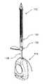
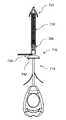
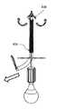
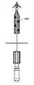
도 1은 본 발명의 제 1 실시예에 따른 외과 시스템의 사시도로서, 임플란트 및 임플란트를 임플란트하기 위한 디바이스를 도시한 것이다.
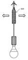
도 2는 전개된 위치에서 도 1의 임플란트의 사시도이다.
도 3은 도 2의 임플란트의 원단 부분의 측면도이다.
도 4는 도 2의 임플란트의 근단 부분의 사시도이다.
도 5는 도 1의 디바이스 및 임플란트의 사시도로서, 사용의 방법예에 따라 피술자의 신체 내에 삽입되는 임플란트를 도시한 것이다.
도 6은 메시를 전개하기 위해 리테이너가 제거된 도 5의 디바이스 및 임플란트를 도시한 것이다.
도 7은 메시가 장력이 부여된 도 6의 디바이스 및 임플란트를 도시한 것이다.
도 8은 메시가 장력이 부여되지 않은 도 6의 임플란트의 상측 부분의 측면도이다.
도 9는 메시가 장력이 부여된 도 8의 임플란트의 상측 부분을 도시한 것이다.
도 10은 메시가 장력이 부여된 도 9의 임플란트의 상측 부분의 우측 상세도이다.
도 11은 디바이스가 제거된 도 7의 임플란트를 도시한 것이다.
도 12는 과잉의 봉합선이 제거된 도 11의 임플란트를 도시한 것이다.
도 13은 근단 앵커가 제거된 도 12의 임플란트를 도시한 것이다.
도 14는 장기간 사용을 위해 임플란트된 도 13의 임플란트를 도시한 것이다.
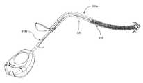
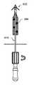
도 15는 본 발명의 제 2 실시예에 따른 외과 시스템의 사시도로서, 임플란트 및 임플란트를 임플란트하기 위한 디바이스를 도시한 것이다.
도 16은 도 15의 외과 시스템의 측면도이다.
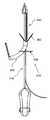
도 17은 전개된 위치에서 도 15의 임플란트의 사시도이다.
도 18은 도 17의 임플란트의 근단 부분의 사시도이다.
도 19는 도 15의 디바이스 및 임플란트의 사시도로서, 사용의 방법예에 따라 피술자의 신체에 삽입된 임플란트를 도시한 것이다.
도 20은 메시를 전개하기 위해 리테이너가 제거된 도 19의 디바이스 및 임플란트를 도시한 것이다.
도 21은 메시가 장력이 부여된 도 20의 디바이스 및 임플란트를 도시한 것이다.
도 22는 장기간 사용을 위해 임플란트된 도 21의 임플란트를 도시한 것이다.
도 23은 대안적 실시예에 따라 외과 시스템의 원단 앵커의 사시도이다.
도 24는 본 발명의 제 3 실시예에 따른 외과 시스템의 사시도로서, 임플란트 및 임플란트를 임플란트하기 위한 디바이스를 도시한 것이다.
도 25는 대안적 실시예에 따라 외과 시스템의 사시도이다.
도 26은 본 발명의 제 4 실시예에 따른 외과 시스템의 임플란트의 사시도이다.
도 27은 도 26의 디바이스 및 임플란트의 측면도로서, 피술자의 신체 내에 삽입된 임플란트 및 메시를 전개하기 위해 제거된 리테이너를 도시한 것이다.
도 28은 메시가 전개된 도 27의 디바이스 및 임플란트를 도시한 사시도이다.
도 29는 메시의 기부가 더욱 전개된 도 28의 임플란트를 도시한 것이다.
도 30은 대안적 실시예에 따른 외과 시스템의 메시의 사시도이다.
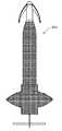
도 31은 본 발명의 제 5 실시예에 따른 외과 시스템의 임플란트의 사시도로서, 전개된 메시 기부를 도시한 것이다.
도 32는 도 31의 임플란트의 측면도이다.
도 33은 본 발명의 제 6 실시예에 따른 외과 시스템의 임플란트의 사시도로서, 전개된 메시 기부를 도시한 것이다.
도 34는 도 33의 임플란트의 측면도이다.
도 35는 본 발명의 제 7 실시예에 따른 외과 시스템의 임플란트의 사시도로서, 전개된 메시 기부를 도시한 것이다.
도 36은 도 35의 임플란트의 측면도이다.
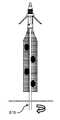
도 37은 본 발명의 제 8 실시예에 따른 외과 시스템의 사시도로서, 임플란트 및 임플란트를 임플란트하기 위한 디바이스를 도시한 것이다.
도 38은 도 37의 디바이스 및 임플란트의 사시도로서, 사용의 방법예에 따라 피술자의 신체에 삽입된 임플란트를 도시한 것이다.
도 39는 리테이너가 제거되고 메시 및 이의 기부가 전개된 도 38의 디바이스 및 임플란트를 도시한 것이다.
도 40은 메시가 장력이 부여된 도 39의 디바이스 및 임플란트를 도시한 것이다.
도 41은 제 1 선택에 따라 니들을 원단쪽으로 전진시킴으로써 메시가 장력이 부여된 도 40의 디바이스 및 임플란트를 도시한 것이다.
도 42는 메시가 완전히 장력이 부여된 도 41의 디바이스 및 임플란트를 도시한 것이다.
도 43은 디바이스가 제거된 도 42의 임플란트를 도시한 것이다.
도 44는 과잉의 봉합선이 제거된 도 43의 임플란트를 도시한 것이다.
도 45는 제 2 선택에 따라 메시가 장력이 부여된 도 40의 임플란트 및 디바이스를 도시한 것이다.
도 46은 디바이스가 제거되고 앵커-판을 원단쪽으로 전진시킴으로써 메시가 장력이 부여된 도 45의 임플란트를 도시한 것이다.
도 47은 디바이스가 제거된 도 46의 임플란트 및 디바이스를 도시한 것이다.
도 48은 과잉의 봉합선이 제거된 도 47의 임플란트 및 디바이스를 도시한 것이다.
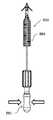
도 49는 본 발명의 제 9 실시예에 따른 외과 시스템의 측면도로서, 임플란트 및 임플란트를 임플란트하기 위한 디바이스를 도시한 것이다.
도 50은 도 49의 디바이스의 핸들 및 니들의 사시도이다.
도 51은 도 49의 디바이스의 글루 디스펜서의 사시도이다.
도 52는 도 49의 디바이스의 리테이너 튜브의 사시도이다.
도 53은 전개된 위치에서 도 49의 임플란트의 측면도이다.
도 54는 도 53의 임플란트의 원단 앵커 및 원단 단부의 사시도이다.
도 55는 도 53의 원단 앵커의 회전 요소의 사시도이다.
도 56은 도 53의 원단 앵커의 고정 요소의 사시도이다.
도 57은 사용의 방법예에 따라 임플란트할 준비가 된 도 49의 디바이스 및 임플란트의 측면도이다.
도 58은 도 57의 디바이스 및 임플란트의 사시도로서, 피술자의 신체 내에 삽입된 임플란트를 도시한 것이다.
도 59는 리테이너가 제거되고 원단 앵커가 전개한 도 58의 디바이스 및 임플란트를 도시한 것이다.
도 60은 도 59의 디바이스 및 임플란트의 측면도로서, 제거된 리테이너 및 전개된 메시를 도시한 것이다.
도 61은 글루 디스펜서가 작동된 도 60의 디바이스 및 임플란트를 도시한 것이다.
도 62는 글루가 메시 상에 배출된 도 61의 임플란트를 도시한 것이다.
도 63은 글루 스폿들이 메시 상에 형성된 도 62의 임플란트를 도시한 것이다.
도 64는 핸들 및 니들을 회전시킴으로써 메시가 장력이 부여되는 도 63의 임플란트를 도시한 것이다.
도 65는 메시가 장력이 부여된 도 64의 임플란트를 도시한 것이다.
도 66은 핸들 및 니들을 역회전시킴으로써 디바이스가 제거된 도 65의 임플란트를 도시한 것이다.
도 67은 장기간 사용을 위해 임플란트된 도 66의 임플란트를 도시한 것이다.
도 68은 본 발명의 제 10 실시예에 따른 외과 시스템의 사시도로서, 임플란트 및 임플란트를 임플란트하기 위한 디바이스를 도시한 것이다.
도 69는 도 68의 임플란트의 커넥터 샤프트, 원단 앵커, 및 근단 앵커의 사시도이다.
도 70은 함께 조립된 도 68의 임플란트의 커넥터 샤프트, 원단 앵커, 및 근단 앵커를 도시한 것이다.
도 71은 근단 앵커 및 도 68의 임플란트의 커넥터 샤프트의 근단 부분의 측면도이다.
도 72는 사용의 방법예에 따라 임플란트할 준비가 된 도 68의 디바이스 및 임플란트의 측면도이다.
도 73은 도 72의 디바이스 및 임플란트의 사시도로서, 피술자의 신체 내에 삽입된 임플란트를 도시한 것이다.
도 74는 도 73의 디바이스 및 임플란트의 측면도로서, 제거된 리테이너 및 전개된 원단 앵커를 도시한 것이다.
도 75는 리테이너가 제거되고 메시 및 근단 앵커가 전개된 도 74의 디바이스 및 임플란트를 도시한 것이다.
도 76은 핸들 및 니들을 회전시킴으로써 메시가 장력이 부여된 도 75의 디바이스 및 임플란트를 도시한 것이다.
도 77은 메시가 장력이 부여된 도 76의 임플란트를 도시한 것이다.
도 78은 메시가 제거된 도 77의 임플란트를 도시한 것이다.
도 79는 장기간 사용을 위해 임플란트된 도 78의 임플란트를 도시한 것이다.
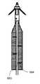
도 80은 본 발명의 제 11 실시예에 따른 외과 시스템의 사시도로서, 임플란트 및 임플란트를 임플란트하기 위한 디바이스, 및 마취약을 이송하기 위한 주사기와 함께 도시되었다.
도 81은 도 80의 외과 시스템의 사시도로서, 절결한 부분과 함께 글루 디스펜서를 도시한 것이다.
도 82은 도 81의 글루 디스펜서의 사시도이다.
도 83은 도 81의 글루 디스펜서의 원단 부분의 측면도이다.
도 84는 도 81의 글루 디스펜서의 근단 부분의 측면도이다.
도 85는 도 80의 임플란트의 원단 앵커의 고정 요소의 측면도이다.
도 86은 도 85의 고정 요소의 사시도이다.
도 87은 리테이너가 제거된 도 80의 디바이스 및 임플란트의 사시도이다.
도 88은 도 87의 임플란트의 원단 부분을 도시한 것이다.
도 89는 도 88의 메시의 부분의 상세도이다.
도 90은 대안적 실시예에 따른 임플란트의 메시의 사시도이다.
도 91은 도 88의 메시의 부분의 상세도이다.
도 92은 또 다른 대안적 실시예에 따른 임플란트의 메시의 부분의 사시도이다.
도 93은 도 92의 메시의 부분의 상세도이다.1 is a perspective view of a surgical system according to a first embodiment of the present invention, showing an implant and a device for implanting an implant.
FIG. 2 is a perspective view of the implant of FIG. 1 in the deployed position. FIG.
3 is a side view of the distal end of the implant of FIG. 2.
4 is a perspective view of the proximal end of the implant of FIG. 2.
FIG. 5 is a perspective view of the device and implant of FIG. 1, illustrating an implant inserted into the body of a subject in accordance with an example method of use. FIG.
FIG. 6 shows the device and implant of FIG. 5 with the retainer removed to deploy the mesh. FIG.
FIG. 7 shows the device and implant of FIG. 6 with the mesh tensioned. FIG.
8 is a side view of the upper portion of the implant of FIG. 6 with no mesh tensioned;
FIG. 9 shows the upper portion of the implant of FIG. 8 with the mesh tensioned. FIG.
10 is a right detail view of the upper portion of the implant of FIG. 9 with the mesh tensioned.
FIG. 11 shows the implant of FIG. 7 with the device removed. FIG.
FIG. 12 shows the implant of FIG. 11 with excess suture removed. FIG.
FIG. 13 shows the implant of FIG. 12 with the proximal anchor removed. FIG.
FIG. 14 shows the implant of FIG. 13 implanted for long term use.
15 is a perspective view of a surgical system according to a second embodiment of the present invention, showing an implant and a device for implanting an implant.
16 is a side view of the surgical system of FIG. 15.
17 is a perspective view of the implant of FIG. 15 in a deployed position.
18 is a perspective view of the proximal end of the implant of FIG. 17.
FIG. 19 is a perspective view of the device and implant of FIG. 15, illustrating an implant inserted into a body of a subject in accordance with an example method of use. FIG.
20 illustrates the device and implant of FIG. 19 with the retainer removed to deploy the mesh.
FIG. 21 illustrates the device and implant of FIG. 20 with the mesh tensioned.
FIG. 22 shows the implant of FIG. 21 implanted for long term use.
23 is a perspective view of a distal anchor of a surgical system in accordance with an alternative embodiment.
24 is a perspective view of a surgical system according to a third embodiment of the present invention, showing an implant and a device for implanting the implant.
25 is a perspective view of a surgical system according to an alternative embodiment.
26 is a perspective view of an implant of a surgical system according to a fourth embodiment of the present invention.
FIG. 27 is a side view of the device and implant of FIG. 26 showing the retainer removed to deploy the implant and mesh inserted into the body of the subject.
FIG. 28 is a perspective view of the device and implant of FIG. 27 with a mesh deployed. FIG.
FIG. 29 illustrates the implant of FIG. 28 with the base of the mesh further deployed.
30 is a perspective view of a mesh of a surgical system according to an alternative embodiment.
31 is a perspective view of an implant of a surgical system according to a fifth embodiment of the present invention, showing the deployed mesh base.
32 is a side view of the implant of FIG. 31.
33 is a perspective view of an implant of a surgical system according to a sixth embodiment of the present invention, showing the deployed mesh base.
34 is a side view of the implant of FIG. 33.
35 is a perspective view of an implant of the surgical system according to the seventh embodiment of the present invention, showing the deployed mesh base.
36 is a side view of the implant of FIG. 35.
37 is a perspective view of a surgical system according to an eighth embodiment of the present invention, showing an implant and a device for implanting an implant.
FIG. 38 is a perspective view of the device and implant of FIG. 37, illustrating an implant inserted into the body of a subject in accordance with an example method of use. FIG.
FIG. 39 illustrates the device and implant of FIG. 38 with the retainer removed and the mesh and its base deployed.
FIG. 40 illustrates the device and implant of FIG. 39 with the mesh tensioned.
FIG. 41 illustrates the device and implant of FIG. 40 with the mesh tensioned by advancing the needle toward the distal end according to the first selection.
FIG. 42 illustrates the device and implant of FIG. 41 with the mesh fully tensioned.
FIG. 43 illustrates the implant of FIG. 42 with the device removed.
FIG. 44 illustrates the implant of FIG. 43 with excess sutures removed.
45 illustrates the implant and device of FIG. 40 with the mesh tensioned according to a second selection.
FIG. 46 illustrates the implant of FIG. 45 with the device tensioned and the mesh tensioned by advancing the anchor-plate toward the distal end.
FIG. 47 illustrates the implant and device of FIG. 46 with the device removed.
FIG. 48 illustrates the implant and device of FIG. 47 with excess sutures removed.
49 is a side view of a surgical system according to a ninth embodiment of the present invention, illustrating an implant and a device for implanting an implant.
50 is a perspective view of a handle and a needle of the device of FIG. 49;
FIG. 51 is a perspective view of the glue dispenser of the device of FIG. 49. FIG.
52 is a perspective view of a retainer tube of the device of FIG. 49.
53 is a side view of the implant of FIG. 49 in a deployed position.
FIG. 54 is a perspective view of the distal anchor and distal end of the implant of FIG. 53. FIG.
55 is a perspective view of a rotating element of the far end anchor of FIG. 53.
56 is a perspective view of the securing element of the far end anchor of FIG. 53.
57 is a side view of the device and implant of FIG. 49 ready for implantation according to an example method of use.
FIG. 58 is a perspective view of the device and implant of FIG. 57, illustrating an implant inserted into the body of a subject. FIG.
FIG. 59 shows the device and implant of FIG. 58 with the retainer removed and the far end anchor deployed. FIG.
FIG. 60 is a side view of the device and implant of FIG. 59 showing the retainer and the deployed mesh removed. FIG.
FIG. 61 shows the device and implant of FIG. 60 with the glue dispenser operated. FIG.
FIG. 62 shows the implant of FIG. 61 with glue ejected onto the mesh.
FIG. 63 illustrates the implant of FIG. 62 with glue spots formed on the mesh.
FIG. 64 illustrates the implant of FIG. 63 in which the mesh is tensioned by rotating the handle and needle.
FIG. 65 shows the implant of FIG. 64 with the mesh tensioned.
FIG. 66 shows the implant of FIG. 65 with the device removed by reversing the handle and needle.
FIG. 67 illustrates the implant of FIG. 66 implanted for long term use.
FIG. 68 is a perspective view of a surgical system according to a tenth embodiment of the present invention, illustrating an implant and a device for implanting an implant.
FIG. 69 is a perspective view of the connector shaft, distal anchor, and the near-end anchor of the implant of FIG. 68.
FIG. 70 illustrates the connector shaft, distal anchor, and near-end anchor of the implant of FIG. 68 assembled together.
FIG. 71 is a side view of the proximal end of the proximal anchor and the connector shaft of the implant of FIG. 68; FIG.
72 is a side view of the device and implant of FIG. 68 ready for implantation in accordance with an example method of use.
73 is a perspective view of the device and implant of FIG. 72, illustrating an implant inserted into the body of a subject.
FIG. 74 is a side view of the device and implant of FIG. 73 showing the retainer removed and the deployed distal anchor.
FIG. 75 illustrates the device and implant of FIG. 74 with the retainer removed and the mesh and proximal anchors deployed.
FIG. 76 illustrates the device and implant of FIG. 75 in which the mesh is tensioned by rotating the handle and needle.
FIG. 77 illustrates the implant of FIG. 76 with mesh tensioned.
FIG. 78 shows the implant of FIG. 77 with the mesh removed.
FIG. 79 illustrates the implant of FIG. 78 implanted for long term use.
80 is a perspective view of a surgical system according to an eleventh embodiment of the present invention, shown with an implant, a device for implanting an implant, and a syringe for transporting anesthetics.
FIG. 81 is a perspective view of the surgical system of FIG. 80 showing the glue dispenser with a cutout; FIG.
FIG. 82 is a perspective view of the glue dispenser of FIG. 81.
FIG. 83 is a side view of the distal end of the glue dispenser of FIG. 81. FIG.
FIG. 84 is a side view of the proximal end of the glue dispenser of FIG. 81. FIG.
85 is a side view of the securing element of the far end anchor of the implant of FIG. 80.
86 is a perspective view of the fixing element of FIG. 85.
FIG. 87 is a perspective view of the device and implant of FIG. 80 with the retainer removed. FIG.
88 illustrates the distal end of the implant of FIG. 87.
FIG. 89 is a detail view of a portion of the mesh of FIG. 88.
90 is a perspective view of a mesh of an implant according to an alternative embodiment.
FIG. 91 is a detail view of a portion of the mesh of FIG. 88.
92 is a perspective view of a portion of a mesh of an implant according to another alternative embodiment.
93 is a detail view of a portion of the mesh of FIG. 92.
일반적으로 기술하여 본 발명은 요실금과 같은 질병을 치료하기 위한 시스템들 및 방법들에 관한 것이다. 시스템들 각각은 외과 임플란트 및 외과 임플란트를 사람 또는 다른 동물 피술자 내에 임플란트하기 위한 외과 장치/디바이스/구현을 포함한다. 또한, 방법들 각각은 외과 임플란트를 사람 또는 다른 동물 피술자 내에 임플란트하기 위해 외과 장치를 사용하기 위한 외과 절차들을 포함한다. 임플란트 및 장치, 및 이들의 사용 방법이 여성 사람들에서 요실금을 치료하는데 사용하기 위해 본원에서 기술되지만, 당업자들은 이들을 남성들 및/또는 다른 동물들에서 동일한 혹은 다른 질병을 외과적으로 치료하는데 사용하기 위해 개조하는 방법을 알 것이다.
Generally described, the present invention relates to systems and methods for treating diseases such as urinary incontinence. Each of the systems includes a surgical device / device / implementation for implanting a surgical implant and surgical implant in a human or other animal subject. Each of the methods also includes surgical procedures for using the surgical device to implant the surgical implant in a human or other animal subject. Although implants and devices, and methods of use thereof, are described herein for use in treating urinary incontinence in female people, those skilled in the art will use them to surgically treat the same or different diseases in men and / or other animals. You will know how to convert.
도 1 ~ 도 14는 외과 시스템을 사용하는 방법뿐만 아니라, 본 발명의 제 1 실시예에 따른 외과 시스템(10)을 도시한 것이다. 외과 시스템(10)은 외과 임플란트(12) 및 외과 임플란트를 피술자의 신체에 임플란트하기 위한 외과 장치(14)를 포함한다.
1-14 illustrate a method of using a surgical system, as well as a
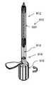
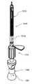
주로 도 1을 참조하면, 외과 장치(14)는 핸들(16), 핸들로부터 확장하는 니들(18), 및 임플란트(12)를 니들 상에 자리에 유지하기 위한 바깥 리테이너(20)를 포함한다. 핸들(16)은 전형적으로 외과 사용자의 한 손 안에 쉽게 손으로 잡아 조작할 수 있게 크기, 형상화되며, 그외가 구성된다. 일부 실시예들에서, 핸들(16)은 피술자 내에 배출하기 위해(예를 들면, 니들(18)의 루멘(lumen)을 통하여, 그리고 예를 들면, 핸들 상에 버튼을 눌러 압착하여 유체를 니들 내로 보냄으로써) 유체(예를 들면, 에폭시, 식염수 또는 또 다른 세척약, 또는 마취제 또는 또 다른 약물)를 저장하는 중공 부분(예를 들면, 가요성 라이너(liner)를 가진)을 갖는다. 핸들(16)은 이 기술에 공지된 제조 기술들을 사용하여 플라스틱, 금속, 합성물, 또는 다른 물질로 만들어질 수 있다.
Referring primarily to FIG. 1,
니들(18)은 핸들(16)로부터 확장하는 근단 단부(24)와 조직에 구멍을 내기 위한 예리한 원단 단부(26)를 가진 긴 샤프트(22)를 포함한다. 일부 실시예들에서, 니들(18)은 이 내에 형성된 것으로서 피술자 내에 유체(예를 들면, 핸들(16) 내에 저장되는, 예를 들면, 에폭시, 식염수 또는 또 다른 세척약, 또는 마취제 또는 또 다른 약물)을 배출하는 루멘을 갖는다. 니들(18)은 이 기술에 공지된 제조 기술들을 사용하여 금속, 플라스틱, 합성물, 또는 다른 물질로 만들어질 수 있다.
그리고, 바깥 리테이너(20)는 임플란트하기 위해 임플란트를 니들에 유지하게 니들(18) 상에 위치되며, 일단 니들이 자리에 삽입되면 임플란트가 리테이너가 없는 니들로부터 피술자의 신체 내 자리 안으로 전개될 수 있게 제거될 수 있다. 리테이너(20)는 니들(18)이 위치 내에 삽입된 상태에서 리테이너를 제거하고 그럼으로써 임플란트(12)를 피술자의 신체 내에 자리 안에 전개하는 조작/작업을 위해 사용자에 의해 접근될 수 있는 분리 부재(28)를 포함할 수 있다. 리테이너(20)는 이 기술에 공지된 제조 기술들을 사용하여 플라스틱(예를 들면, 투명한 연한 비닐), 금속, 합성물, 또는 그외 다른 물질로 만들어질 수 있다.
The
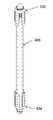
도시된 실시예에서, 예를 들면, 리테이너(20)는 임플란트(12)(또는 적어도 메시 및 이의 근단 앵커)의 길이를 실질적으로 확장하고 이를 덮는 튜브에 의해 제공되며, 이의 길이(도 52 참조)를 따라 확장하는 길이방향의 파괴 지역(29)을 가지며, 탄성적으로 편향가능한 물질로 만들어진다. 도시된 실시예에서, 리테이너 튜브(20)는 리테이너가 니들(18) 상에 맞추어졌을 때 다른 숨겨진 밑에 있는 임플란트(12)가 이를 통해 보여질 수 있도록 대체로 투명한 폴리머로 만들어진다. 분리 부재(28)는 튜브(20)의 근단 단부 부분으로부터 대체로 반경방향으로 바깥쪽으로 확장하는 당김 탭(tab)에 의해 제공된다. 파괴 지역(29)은 분리 부재에 힘을 인가하였을 때 파괴되는 미리 형성된 슬릿, 천공된 혹은 스코어 라인에 의해서, 혹은 보유 폐쇄 위치에서 방면 개방 위치로 편향하게 튜브(20)가 조작될 수 있게 하는 또 다른 유형의 길이방향의 파괴 지역에 의해 제공될 수 있다. 리테이너 튜브(20)가 임플란트(12)에 걸쳐 니들(18) 상에 장착된 상태에서, 튜브는 보유 폐쇄 위치로 반경방향으로 안쪽으로 탄성적으로 바이어스되어 피술자의 신체 내에 삽입하기 위한 니들에 의해 운반되는 임플란트를 보유한다. 또한, 니들(18)이 피술자의 신체 내에 삽입된 상태에서, 리테이너 튜브(20)는 임플란트를 피술자의 신체 내에 전개하여 놔두기 위해서 니들 및 임플란트(12)로부터 제거하기 위한 방면 개방 위치로 탄성적으로 편향하게 조작될 수 있다. 예를 들면, 리테이너 튜브(20)는 파괴 지역(29)을 따라 열리게 튜브를 당기고 이를 니들(18)로부터 끌어/미끄러지게 내리기 위해 당김-탭 분리 부재(28)를 당김으로써 방면 개방 위치로 탄성적으로 편향하게 조작될 수 있다.
In the illustrated embodiment, for example, the
다른 실시예들에서, 리테이너는 본원에 기술된 임플란트 보유 및 방면/전개 기능을 제공하게 개조된 시스(sheath), 케이지, 코일, 스크롤, 클립, 클램프, 클래스프, 망원 조립체, 팬-날개 조립체, 또는 그외 다른 구조 또는 조립체에 의해 제공된다. 일부 이러한 실시예들에서, 리테이너가 본원에 기술된 바와 같은 이의 의도된 기능을 수행하기 위해 파괴 지역 및 분리 부재가 제공될 필요는 없다. 또한, 다른 실시예들에서, 분리 부재는 본원에 기술된 임플란트 보유 및 전개 기능을 제공하게 개조된 축상으로 확장하는 당김 탭 또는 스트링, 회전 철회 요소, 또는 또 다른 구조 또는 조립체에 의해 제공된다.
In other embodiments, the retainer may be a sheath, cage, coil, scroll, clip, clamp, clasp, telephoto assembly, fan-wing assembly, adapted to provide the implant retention and orientation / deployment functions described herein. Or by other structures or assemblies. In some such embodiments, it is not necessary for the retainer to be provided with a breaking zone and separation member in order to perform its intended function as described herein. Further, in other embodiments, the separating member is provided by an axially extending pull tab or string, rotational retraction element, or another structure or assembly adapted to provide the implant retention and deployment function described herein.
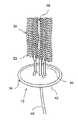
주로 도 2 ~ 도 4를 참조하면, 외과 임플란트(12)는 외과 메시 슬링(sling), 및 피술자의 신체 내 자리에 임플란트된 메시를 고정하기 위한 하나 이상의 앵커들을 포함한다. 도시된 실시예에서, 예를 들면, 외과 임플란트(12)는 외과 메시(30), 원단 앵커(32), 근단 앵커(34), 및 임플란트된 메시를 원단 앵커와 근단 앵커 사이에서 장력을 부여하기 위한 메시-장력부여 조립체(36)를 포함한다. 다른 실시예들에서, 임플란트(12)의 일체된 부분으로서 원단 또는 근단 앵커만이 제공되고, 메시(30)의 다른 단부는 예를 들면 별도로 제공된 봉합선들 또는 에폭시(이 발명의 목적들을 위해 앵커들로 간주된다)에 의해 자리에 고정된다. 그리고, 다른 실시예들에서, 메시 장력부여는 예를 들면 메시를 미리 장력이 부여된 상태에서 임플란트함으로써, 혹은 메시를 위한 장력부여 조립체를 포함하는 임플란트 또는 장치 없이 메시의 근단 단부를 당김으로써 제공된다.
Referring primarily to FIGS. 2-4, the
도시된 실시예에서, 외과 메시(30)는 폴리프로필렌과 같은 탄성적으로 가요성있는 생체적합 물질로 만들어지는 긴, 가요성 있는, 시트같은 메시 또는 격자 스크린이다. 다른 실시예들에서, 메시는 진정한 메시 또는 격자 스크린이 아니며 그보다는 고형이거나, 천공되거나, 직조되거나, 아니면 본원에 기술된 바와 같이 의도된 슬링 사용을 위해 구성되어 만들어질 수 있는 물질의 시트, 패널, 혹은 스트립이다. 전형적인 상업적인 실시예에서, 메시(30)는 요망될 수 있는 대로 더 길거나 더 짧을 수 있을지라도, 약 40mm 길이이다. 외과 메시(30)는 피술자의 신체 내에 삽입할 준비가 된 저장된 위치로 장치(14)에 의해 수용된다(예를 들면, 바깥 튜브 리테이너(20)와 니들 샤프트(22) 사이에). 예를 들면, 저장된 위치에서 메시(30)는 니들(18) 둘레에 조밀한(compact) 길이방향 배열로 접어지고(예를 들면, 폴딩(fold) 또는 랩(wrap) 된다) 니들 상에 맞추어진 튜브 리테이너(20)에 의해 보유될 수 있다. 튜브 리테이너(20)를 제거하였을 때, 메시(30)는 사용을 위한 전개된 위치로 측방으로 바깥쪽으로(예를 들면, 메시를 펼쳐지게 하는 물질의 탄성에 의해) 확장된다. 메시(30)가 완전히 자체-전개하는데 충분히 탄성이지 않은 물질로 만들어지는 실시예들에서, 메시는 의사에 의해 전개된 위치로 측방으로 바깥쪽으로 손으로 당겨질 수 있다. 일부 실시예들에서, 외과 메시(혹은 적어도 이의 부분들)는 생체흡수가능 물질(예를 들면, 통상의 생체흡수가능 봉합선들에서 사용되는 유형들의)로 만들어진다.
In the illustrated embodiment,
원단 앵커(32)는 메시(30)의 원단 단부(31)에 위치되고 이에 결합되며, 근단 앵커(34)는 메시의 근단 단부(33)에 위치되고 이에 결합된다. 도시된 실시예에서, 원단 앵커(32)는 몸체(36) 및 몸체로부터 측방으로 확장하는 하나 이상의(예를 들면, 도시된 바와 같이, 2개) 바브들(38)을 갖는다. 바브들(38)은 원단 앵커(32)를 자리에 고정하기 위해 조직 내에 건다. 도시된 실시예에서, 바브들(38)은 보유 폐쇄 위치에서 리테이너(20)의 원단 단부로부터 원단쪽으로 위치되고, 이에 따라 니들(18) 및 임플란트(12) 삽입(이들이 전형적으로 작은 치수의 외과 절개를 통해 삽입시 얼마간 안쪽으로 편향할지라도) 동안에 반경방향으로 안쪽 위치에 보유되지 않고 리테이너 제거시 반경방향으로 바깥쪽으로 전개된다. 다른 실시예들에서, 바브들은 보유 폐쇄 위치에서 리테이너의 원단 단부로부터 근단쪽으로 위치되고 이에 따라 이들은 니들 및 임플란트 삽입 동안 반경방향으로 안쪽 위치에 보유되고 이어 리테이너의 제거시 탄성적으로 편향되어 반경방향으로 바깥쪽으로 전개된다. 그리고, 원단-앵커 몸체(36)는 니들(18)에 의해 맞물리는 수용부(40)(예를 들면, 도시된 바와 같이 중앙 애퍼처, 혹은 측방으로 위치된 애퍼처 또는 노치)를 포함하고 따라서 니들을 피술자의 신체 내에 삽입할 때 원단 앵커(32)는 앵커링을 위해 니들에 의해 임플란트 부위까지 운반된다.
The
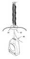
도시된 실시예의 근단 앵커(34)는 메시(30)의 근단 단부에 위치되고 이에 결합되는 판(예를 들면, 디스크 또는 매끄러운 끝부분들을 가진 그외 다른 형상의 판)(42)에 의해 제공된다. 전형적으로, 앵커-디스크(42)는 플라스틱과 같은 생체적합 물질로 만들어지고 하나 이상의 메시-대-앵커 커넥터들(44)로 메시(30)의 근단 단부에 고정된다. 메시-대-앵커 커넥터들(44)은 메시(30)를 근단 앵커(34)에 결합하기 위한 통상의 봉합선들, 스트링들, 코드들, 타이들, 또는 그외 다른 통상의 연결 요소들에 의해 제공될 수 있다. 예를 들면, 도시된 실시예에서, 앵커-디스크(42)는 2개의 통상의 생체흡수가능 봉합선들(44)로 메시(30)에 고정된다. 메시(30)가 임플란트되었을 때, 앵커-디스크(42)는 메시가 조직과 일체가 되고 이에 따라 자리에 고정될 때까지 질 피부를 들어올려진 위치에 고정하기 위해 피술자의 신체의 질 피부 밖에 이에 대항하여 위치된 채로 있게 된다. 생체흡수가능 봉합선들(44)은 이들이 메시(30)가 조직과 일체가 되어 자리에 고정하게 되는데 충분한 시간 -이 시간에 앵커-디스크(42)(흡수가능한 봉합선들에 의해 메시에 부착된다)는 메시로부터 분리하고 피술자의 신체로부터 자유롭게 떨어진다- 후에 피술자의 신체 내에 흡수되게 선택된다.
The
다른 실시예들에서, 원단 및/또는 근단 앵커들은 본원에 기술된 메시-앵커링 기능을 제공하기 위해 선택된 다른 통상의 앵커 요소들에 의해 제공될 수 있다. 예를 들면, 원단 및/또는 근단 앵커들은 메시로부터 확장하여 교시된 메시를 당기기 위해 요도 주위 조직들 내에 걸어질 수 있는 복수의 작은 원단 및/또는 근단 바브들(예를 들면, 통상의 바브 봉합선들 상에 포함된 유형의)에 의해 제공될 수 있다. 이러한 실시예들에서, 바브들은 이들이 메시의 설치에 간섭하지는 않으나 일단 메시가 자리에 임플란트되면 바브들이 메시를 인접 조직에 고정하는데 도움을 주게 메시에 결합되거나 이와 일체로 형성될 수 있다.
In other embodiments, the far end and / or near-end anchors may be provided by other conventional anchor elements selected to provide the mesh-anchoring function described herein. For example, the distal and / or near-end anchors may be a plurality of small distal and / or near-end barbs (eg, conventional barb sutures) that may be hooked into the tissues around the urethra to pull the taught mesh extending from the mesh. Of the type contained therein). In such embodiments, the barbs may be coupled to or integrally formed with the mesh to help the barbs secure the mesh to adjacent tissue once they are implanted in place but do not interfere with the mesh's installation.
외과 임플란트(12)의 메시-장력부여 조립체(36)는 임플란트된 메시(30)를 원단 앵커들(32)과 근단 앵커(34) 사이에서 장력을 부여하게 개조된다. 장력부여 조립체(36)는 메시(30)에서 원단 앵커(32) 쪽으로 확장하고, 원단 앵커와 미끄럼 맞물리고, 사용자가 장력부여 스트링을 근단쪽으로 당겨 그럼으로써 메시에 장력을 부여하기 위해 메시의 원단 단부(31)를 원단쪽으로 당길 수 있도록 근단 앵커(34) 쪽으로 근단쪽으로 확장하는, 적어도 한 원단-장력부여 스트링을 포함할 수 있다. 이에 따라, 장력부여 스트링과 원단 앵커(32)와의 맞물림은 장력부여 스트링에 인가되는 근단 장력부여 힘을 메시(30)에 인가되는 원단 장력부여 힘으로 전환하게 기능한다.
The mesh-tensioning
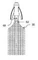
예를 들면, 도시된 실시예의 메시-장력부여 조립체(36)는 원단-장력부여 스트링(46) 및 원단 앵커(32) 내에 측방 개구(48)를 포함하고, 장력부여 스트링은 메시(30)의 원단 단부(31)로부터 원단쪽으로, 원단-앵커 개구를 측방에서 통과하여, 메시 및 근단 앵커(34)를 근단쪽으로 지나 확장한다. 장력부여 스트링(46)은 통상의 봉합선, 스트링, 코드, 스트립, 또는 그외 다른 가요성있는 긴 요소에 의해 제공될 수 있다. 장력부여 스트링(46)은 메시(30)와 선형으로 나란히 이어질 수 있고, 혹은 이것은 메시에 장력을 부여하는데 도움을 주게 메시를 통해 직조될 수 있다. 또한, 장력부여 스트링(46)은 근단 앵커(34) 내(예를 들면, 이의 디스크-판(42) 내) 개구(예를 들면, 도시된 중심 축상의 애퍼처, 또는 노치, 홈, 또는 중심-일탈 개구)(49)를 통과하여 이어질 수 있다. 장력부여 스트링(46) 및 니들 샤프트(22)는 근단-앵커 디스크-판(42) 내 동일 개구를 통하여, 혹은 별도의/전용의 개구들을 통하여 확장할 수 있다. 따라서, 근단-앵커 디스크-판(42) 밑에 장력부여 스트링(46)의 자유 단부를 당기는 것은 메시(30)를 원단 앵커(32) 쪽으로 원단쪽으로 위로 당겨 요망되는 만큼 메시에 장력을 부여한다. 또한, 원단 앵커(32) 내 개구(48)는 원단 앵커로부터 근단쪽으로 확장하는 탭(50) 내 형성되는 애퍼처(도시된 바와 같은), 노치, 홈, 등에 의해 제공될 수 있다.
For example, the mesh-tensioning
이렇게 하여, 장력부여 스트링(46) 및 원단-앵커 개구(48)는 메시에 장력을 부여하기 위해 장력부여 스트링 상에 근단/아래쪽으로의 힘을 메시(30) 상에 원단/위쪽으로의 힘으로 전환하는 힘-역전 풀리 또는 윈치 메시-장력부여 조립체를 형성한다. 대안적 실시예들에서, 메시에 장력을 부여하기 위해 장력부여 스트링(또는 그외 다른 장력부여 요소) 상에 근단/아래쪽으로의 힘을 메시 상에 원단/위쪽으로의 힘으로 전환하기 위해 다른 통상의 유형들의 힘-역전 조립체들이 구현된다. 이러한 대안적 힘-역전 조립체들은 라체팅 시스템들, 미니-기어 시스템들, 등을 포함할 수 있다. 그리고, 다른 실시예들에서, 메시에 장력을 부여하기 위해 이의 원단 단부를 "당기는" 힘-역전 조립체 대신에, 장력부여 조립체는 이의 원단 단부를 원단쪽으로 밀어 메시에 장력을 부여하는 "미는" 요소를 포함한다. 이러한 밀어 장력을 부여하는 요소는 임플란트의 한 부분으로서 일체로 제공될 수 있고, 혹은 이것은 별도로 제공될 수 있다(예를 들면, 메시 원단 단부에서 소켓 또는 캐치에 의해 수용되는 통상의 외과 도구).
In this way, the
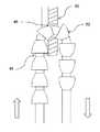
또한, 장력부여 스트링(46)은 일방향 전진(도 8 ~ 도 10 참조)을 제공하기 위해 원단 앵커(32) 내 측방 개구(48)에 관하여 크기 및 형상화된 테이퍼된 이끔(leading) 표면들 및 가로놓인 끌림(trailing) 표면들을 가진 일련의 일방향 기계식 멈추개들(52)을 포함할 수 있다. 기계식 멈추개들(52)은, 예를 들면, 웨지 형상, Y-형상, 돔-형상, 또는 장력부여 스트링(46)에 일체로 형성되거나 그에 부착된 다른-테이퍼된 노트들, 또는 다른 몸체들에 의해 제공될 수 있다. 일부 실시예들에서, 일방향 기계식 멈추개들(52)을 가진 장력부여 스트링(46)은 통상의 바브 봉합선에 의해 제공된다. 기계식 멈추개들(52)은 탄성적으로 안쪽으로 편향하는 이들의 테이퍼된 이끔 표면들에 의해 일방향으로(도 10의 우측에 방향 화살표로 나타낸 바와 같이) 원단 앵커(32) 내 측방 개구(48)를 통과하여 당겨질 수 있다. 그러나 이들은 이들의 가로놓인 끌림 표면들이 개구의 것보다 큰 주변 치수를 갖고 있어 기계식 멈추개들(52)이 개구를 통해 뒤로 지나가지 못하게 하기 때문에, 적어도 멈추개들 또는 개구를 손상시키지 않고는, 반대 방향(도 10의 좌측에 방향 화살표로 나타낸 바와 같이)으로 원단 앵커(32) 내 측방 개구(48)를 통과하여 당겨질 수 없다. 이렇게 하여, 일단 개구(48)를 통과하여 당겨지면, 멈추개들(52)은 장력부여 스트링(46)을 증분적으로 증가된 장력부여의 위치들에 고착시켜 뒤쪽으로 느슨해지는 것을 방지한다. 이것은 원단-앵커 개구(48)를 통과하여 하나 이상의 추가의 기계식 멈추개들(52)을 당김으로써 더 큰 억제를 위해 의사가 메시(30) 상에 장력을 조일 수 있게 함으로써 수술후 조절가능성을 갖게 한다. 이러한 이유로, 장력부여 스트링(46)은 의사가 필요하다면 나중에(초기 설치 후에) 메시를 조일 수 있도록 메시(30)가 임플란트된 후에 전형적으로 질 내에 남겨진다.
In addition, the
다른 실시예들에서, 장력부여 스트링(46)은 기계식 멈추개들없이 제공되고 메시 상에 장력을 유지하기 위해 자체, 메시(30), 원단 앵커(32), 근단 앵커(34), 임플란트(12)의 또 다른 부분, 또는 피술자의 신체에 고정된다(예를 들면, 묶거나 봉합에 의해). 일부 다른 실시예들에서, 기계식 멈추개들(52)은 근단 앵커(34) 내 개구(49)를 통과하여 이어지는(원단-앵커 개구(48)를 통과하여 이어지는 장력부여 스트링의 부분을 따라 위치되는 대신에) 장력부여 스트링(46)의 부분을 따라 확장하며, 근단-앵커 개구는 장력부여를 위해 일방향 전진을 제공하기 위해 기계식 멈추개들에 관하여 크기 및 형상화된다.
In other embodiments, tensioning
주로 도 5 ~ 도 14를 참조하면, 장치(14)를 사용하여 임플란트(12)를 임플란트하는 방법이 이제 기술될 것이다. 도 5는 피술자의 신체 내 자리에 삽입된, 외과 임플란트(12)를 유지하는 외과 장치(14)를 도시한 것이다. 따라서 의사는 원단-지향의 힘을 핸들(16)에 가함으로써 시스템(10)을 위치시키는데, 이것은 장치(14)의 니들(18)의 예리한 원단 단부(26)가 피술자의 피부(8)에 구멍을 내게 하여 메시(30)를 설치하기 위한 요망되는 위치로 니들이 피술자의 신체 내에 삽입될 수 있게 한다. 장치(14)는 원단 앵커(32)가 요망되는 위치에 조직 내에 장치되고 근단 앵커(34)가 밖에 그리고 전형적으로 피부(8)에 인접하게 위치될 때까지 전진된다. 이어서 원단 앵커(32)가 자리에 고정된 상태에서, 분리 부재(28)는 보유 폐쇄 위치(도 5)에서 방면 개방 위치(도시되지 않음)로 리테이너(20)를 당겨 장치(14)(도 6)로부터 떨어지게 조작된다. 이것은 반경방향으로 바깥쪽/측방이고(파괴 지역(29)을 열고 리테이너(20)를 보유 폐쇄 위치에서 방면 개방 위치로 당기기 위해) 축상으로 아래쪽/근단쪽(방면된 리테이너를 니들(18)로부터 피술자의 신체 밖으로 슬라이딩하기 위해) 방향으로 분리 부재(28)를 당김으로써 행해질 수 있다. 이것은 이어 탄성 메시(30)가 펼쳐져 이에 따라 저장된 위치(도 5)에서 전개된 위치(도 6)로 전개할 수 있게 한다.
Referring primarily to FIGS. 5-14, a method of implanting
이때, 의사는 장력부여 스트링(46)을 근단쪽으로 당기는데, 이에 따라 메시(30)를 원단쪽으로 당기게 되어 이를 원단 앵커(32) 쪽으로 당기고 따라서 근단-앵커 디스크-판(42)을 이의 들어올려진 위치(도 7)로 당긴다. 추가적으로 혹은 대안적으로, 니들(18)은 기계식 멈추개(예를 들면, 핀, 탭, 또는 그외 다른 돌기) -이 위에 디스크-판(42)이 위치되고 니들에 관하여 근단 이동으로부터 유지된다- 을 포함할 수 있고, 의사는 장력부여 스트링(46)을 당김으로써 메시에 장력이 부여될 수 있게 디스크-판(42)을 들어올리고 메시(30) 내에 느슨함을 없애기 위해 핸들(16)을 원단쪽으로 밀 수 있다. 기계식 멈추개들(52)(도 8 ~ 도 10)의 일방향 전진 및 고착 기능은 메시(30)를 이 장력이 부여된 상태로 고착한다. 이어, 장치(14)는 제거되고, 그럼으로써 니들(18)을 원단 앵커(32)의 수용부(40)와의 맞물림으로부터 그리고 피술자의 신체로부터 빼내고, 그럼으로써 임플란트가 자리에 장력이 부여된 상태로 두어 요실금 또는 그외 다른 질병을 치료한다(도 11).
At this time, the surgeon pulls the
임플란트(12)는 요망되는 효과들이 얻어진다면 이 위치에 남겨둘 수 있고, 혹은 그렇지 않다면 의사는 또 다른 하나 이상의 기계식 멈추개들(52)을 원단 앵커 개구(48)(도 8 ~ 도 10)를 통과하여 당기기 위해 장력부여 스트링(46)을 더 당김으로써 수술후에 메시(30)에 더욱 장력을 부여할 수 있다. 일단 메시(30)의 효과적인 장력이 달성되었으면, 의사는 피술자의 신체(도 12) 밖으로 확장하는 장력부여 스트링(46)의 과잉 부분을 제거한다(예를 들면, 잘라낸다).
The
시간이 지남에 따라, 메시(30)를 근단 앵커(34)에 연결하는 생체흡수가능 커넥터들(예를 들면, 봉합선들)(44)은 피술자의 신체에 의해 흡수된다. 이것이 일어났을 때, 근단 앵커(34)는 근단 앵커(34)로부터 분리되어 자유롭게 떨어진다(도 13). 그러면, 임플란트(12)는 이 임플란트된 위치에 남겨지게 되어, 요망되는 효과적인 장력을 장기간 제공하여 요실금 또는 그외 다른 질병을 치료한다(도 14).
Over time, the bioabsorbable connectors (eg, sutures) 44 connecting the
다른 대안적 실시예들에서, 메시의 원단 단부는 원단 앵커에 고정적으로 부착되고, 장력부여 스트링은 제공되지 않으며, 메시의 장력부여는 메시의 근단 단부로부터 근단쪽으로 확장하는 근단-장력부여 스트링을 당김으로써 달성된다. 근단-장력부여 스트링은 기계식 멈추개들을 가질 수 있고 근단 앵커는 근단-장력부여 스트링이 확장하는 개구일 수 있어, 기계식 멈추개들 및 근단-앵커 개구는 공조하여 메시가 장력이 부여된 채로 근단-장력부여 스트링을 자리에 고착시키기 위한 일방향 전진을 제공할 수 있다.
In other alternative embodiments, the distal end of the mesh is fixedly attached to the distal anchor, no tensioning string is provided, and the tensioning of the mesh pulls the near-end tension string extending toward the near end from the near end of the mesh. Is achieved. The proximal-tension string may have mechanical stops and the proximal anchor may be an opening through which the proximal-tension string extends, such that the mechanical stops and the proximal-anchor opening co-operate so that the mesh is tensioned with tension. One way forward may be provided to secure the tensioning string in place.
발명의 제 1 실시예 및 이의 다수의 대안적 실시예들을 기술하였으므로, 발명의 추가의 실시예들은 기술되지 않을 것이다. 본원에 기술된 실시예들의 어느 것의 특징들은 본원에 분명하게 개시되지 않은 발명의 추가의 실시예들을 형성하기 위해 다른 본원에 기술된 실시예들 혹은 다른 개시되지 않은 실시예들의 특징들과 조합될 수 있음이 당업자들에 의해 이해될 것이다.
Having described the first embodiment of the invention and numerous alternative embodiments thereof, further embodiments of the invention will not be described. Features of any of the embodiments described herein may be combined with features of other described embodiments or other non-disclosed embodiments to form further embodiments of the invention that are not expressly disclosed herein. It will be understood by those skilled in the art.
도 15 ~ 도 23은 외과 시스템을 사용하는 방법뿐만 아니라, 본 발명의 제 2 실시예에 따른 외과 시스템(110)을 도시한 것이다. 외과 시스템(110)(도 15 ~ 도 18) 및 방법(도 19 ~ 도 22)은 몇 가지를 제외하고, 제 1 실시예의 것들과 동일하거나 유사하다. 이에 따라, 외과 시스템(110)은 외과 임플란트를 피술자의 피부(108)를 관통하여 이들의 신체 내에 임플란트하기 위한 외과 임플란트(112) 및 외과 장치(114)를 포함한다. 외과 장치(114)는 제 1 실시예의 것과 동일할 수 있다. 그리고 외과 임플란트(112)는 근단 앵커(134)를 제외하고 제 1 실시예의 것과 동일할 수 있다.
15-23 illustrate a method of using a surgical system, as well as a
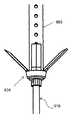
이 실시예에서, 외부에 위치된 앵커-디스크 대신에, 근단 앵커(134)는 메시(130)에 결합된 몸체(154) 및 피술자의 신체 내에 위치시키기 위해 앵커 몸체로부터 확장하는 하나 이상의 접어질 수 있는 바브들(156)을 포함한다. 앵커 몸체(154)는 축상의 구멍(158)을 포함할 수 있고 이를 통해 니들(118)이 사용 동안 확장하고 철회된다. 또한, 앵커 몸체(154)는 메시(30)에 직접 혹은 생체흡수가능 봉합선들과 같은 커넥터들에 의해 고정될 수 있다. 일부 실시예들에서, 근단 앵커(134)(및/또는 원단 앵커(132))는 바브들(156)의 휨을 제한하기 위해 하나 이상의 멈추개들 또는 노치들을 포함한다. 또한, 일부 다른 실시예들에서, 원단 앵커(132) 및 근단 앵커(134) 중 하나 혹은 둘 다는 피술자의 신체 내에 흡수될 수 있는 생체흡수가능 물질로 만들어진다. 선택적으로, 바브들(156)은 이를 관통하는 하나 이상의 홀들 혹은 조직을 잡을 수 있게 하는 오목부들(indentations)을 안에 포함할 수 있다. 또한, 원단 앵커(132) 및 근단 앵커(134) 중 하나 혹은 둘 다는 이로부터 확장하는 부분을 포함할 수 있는데 이에 리테이너(120)가 분리가능하게 결합된다.
In this embodiment, instead of an externally located anchor-disc, the
접어질 수 있는 바브들(156)은 예를 들면 탄성 물질로 만들어진 적어도 한 부분을 포함하고 바이어스하기 위해 스프링 요소들(예를 들면, 생체흡수가능한 탄력있는 원단쪽으로-당겨지는 봉합선들 또는 원단쪽으로-미는 코일들) 포함함으로써 반경방향으로 바깥쪽으로 탄성적으로 바이어스된다. 바브들(156)은 초기에는 저장된 위치에 있는데 이 위치에서 이들은 앵커 몸체(154) 쪽으로/이에 대항하여 반경방향으로 안쪽으로 탄성적으로 편향되고, 이의 보유 폐쇄 위치(리테이너 또한 메시(130)를 저장된 위치에 유지하는)(도 15 ~ 도 16 및 도 19)에서, 예를 들면 바깥 튜브 리테이너 내에 리테이너(120)에 의해 그에 유지된다. 그러나, 임플란트(114)가 환자의 신체 내 자리에 삽입되고 리테이너(120)가 제거된 후에, 바브들(156)은 자유로이 탄성적으로 반경방향으로 바깥쪽으로 편향한다(도 20). 이어, 바브들(156)은 이들이 장력부여를 위해 메시(130)를 자리에 고정하기 위해(도 17 ~ 도 18 및 도 21 ~ 도 22) 조직 내에 거는 이들의 반경방향으로 바깥쪽으로 확장된 위치들로 완전히 전개한다.
또한, 대안적 실시예에서 원단 앵커(132a)는 바브들(138a) 각각이 앵커 몸체(도 23)로부터 확장하는 더 얇고/더 좁은 몸체(136a) 및 홈(예를 들면, 예각 측 상에 슬릿 또는 노치)(158a)을 갖는다. 이것은 메시가 임플란트되고 리테이너가 제거된 후에 바브들(138a)이 전개할 준비가 된, 예를 들면 리테이너에 의해 그에 유지되는 저장된 위치(도시되지 않음)로 바브들(138a)이 탄성적으로 안쪽으로 편향하게 한다.
Also, in an alternative embodiment the
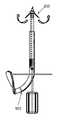
도 24는 몇 가지를 제외하고 제 1 실시예의 것들과 동일하거나 유사한 주요 성분들을 가진, 본 발명의 제 3 실시예에 따른 외과 시스템(310)을 도시한 것이다. 특히, 외과 장치의 니들(318)은 이것이 지금까지 도시된 다른 실시예들에 있는 바와 같이 선형이 아니다. 도시된 실시예에서, 예를 들면, 니들(318)은 한 평면에서 만곡되고, 저장된 위치에 가요성 메시(330) 및 보유 폐쇄 위치에 가요성 리테이너(320)는 한 평면에서 만곡된 순응 형상이다. 도 25에 도시된 대안적 실시예에서, 외과 시스템(310a)은 두 평면들에서 만곡되는 니들(318a)을 포함하고, 저장된 위치에서 가요성 메시(330a) 및 보유 폐쇄 위치에 가요성 리테이너(320a)는 두 평면들에서 만곡된 순응 형상이다.
FIG. 24 illustrates a
일부 실시예들에서, 외과 메시 임플란트는 자리에 마찰 고정을 위한 증가된 표면적을 제공하기 위해 이의 근단 단부에서 측방으로 확장하는 기부(base)를 포함한다. 측방으로 확장하는 기부는 낮은 프로파일을 가진 저장된 안쪽 위치에서 추가의 표면적을 제공하기 위해 측방으로 확장하는 전개된 바깥쪽 위치로 이동한다. 측방 기부는 메시의 수직/길이방향의 부분과 동일하거나 다른 생체적합 물질로 만들어질 수 있다.
In some embodiments, the surgical mesh implant includes a base extending laterally at its proximal end to provide increased surface area for frictional fixation in place. The laterally expanding base moves from the stored inward location with the low profile to the laterally expanding outward location to provide additional surface area. The lateral base can be made of the same or different biocompatible material as the vertical / lengthwise portion of the mesh.
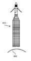
예를 들면, 도 26 ~ 도 30은 본 발명의 제 4 실시예에 따른 외과 시스템(310)을 도시한 것이다. 외과 시스템(310) 및 이의 사용 방법은 몇 가지를 제외하고 제 1 실시예의 것과 동일하거나 유사하다. 이에 따라, 외과 시스템(310)은 외과 임플란트를 피술자의 피부(308)를 관통하여 이들의 신체 내에 임플란트하기 위한 외과 임플란트(312) 및 외과 장치(314)를 포함한다. 외과 장치(314)는 제 1 실시예의 것과 동일할 수 있다. 그리고 외과 임플란트(312)는 메시(330)를 제외하고 제 1 실시예의 것과 동일할 수 있다.
For example, FIGS. 26-30 illustrate a
이 실시예에서, 외과 메시(330)는 이의 근단 단부(333)에 메시의 서로 대향하는 측들로부터 측방으로 확장하며 전개된 위치에 있을 때 메시와 공조하여 반전된 "T"(프로파일에서)의 전반적인 형상을 취하는, 2개의 평탄한 패널들(360)의 형태로 측방으로 확장하는 기부를 포함한다. 측 패널들(360)은 사각형(도시된 바와 같이)일 수 있고 혹은 이들은 또 다른 규칙적인 혹은 불규칙적인 형상(예를 들면, 다각형 혹은 반원형)을 가질 수 있다. 전형적인 상업적 실시예들에서, 메시(330)는 약 25mm의 길이를 가지며, 기부들(360)은 반전된 "T" 형상 메시가 프로파일로 보았을 때, 총체적으로 약 16mm의 길이를 가지며, 메시/기부들의 폭은 메시가 상부/원단 단부에서 보았을 때 약 8mm, 6mm, 또는 5mm이다. 다른 실시예들에서, 측 패널들은 만곡된 끝부분들을 가지며 및/또는 비-수직 위치로 전개된다.
In this embodiment, the
측 패널들(360)을 전개하기 위해서, 이들은 측 패널들의 자유로운 바깥 부분들과 장력부여 스트링(346) 사이에서 확장하는 패널-전개 스트링들(예를 들면, 봉합선들 또는 코드들)(362)을 포함할 수 있다. 이렇게 하여, 니들(318)을 피술자의 신체 내에 삽입하고 리테이너 튜브(320)(도 27 ~ 도 28)를 제거하기 위해 외과 시스템(310)을 사용한 후에, 의사는 장력부여 스트링(346)을 당겨 패널들(360)을 대체로 수평의 전개된 위치로(또한 메시(330)를 원단쪽으로 장력을 부여하면서) 밑으로 전개할 수 있다.
To develop the
또한, 장력부여 스트링(346)은 메시에 장력을 부여하기 위해, 메시(330)로부터 위로/원단쪽으로, 원단 앵커(332)를 통과하고/둘러, 메시 및 근단 앵커(334)를 지나기 위해 반대로 아래쪽/근단쪽으로 이어진다(장력부여 스트링을 아래쪽/근단쪽으로 당기는 것은, 위에 기술된 바와 같이, 메시의 원단 단부를 위쪽으로/원단쪽으로 당긴다). 이 실시예에서, 장력부여 스트링(346)은 근단 앵커-디스크(342)(바브들 및 디스크는 가압하에 약간 편향/변형/압축된다) 내 개구(344)를 통과하여 일방향 전진을 제공하도록 크기 및 형상화된 기계식 멈추개들(352)을 포함한다. 그러나, 일방향 멈추개들(352)은 장력부여 스트링(346)이 반대 방향으로 앵커-디스크(342)에 관하여 반대로 슬라이딩하지 못하게 한다. 이렇게 하여, 의사는 요망되는 만큼 메시(330)에 장력을 부여하기 위해 장력부여 스트링(346)을 당길 수 있고, 그러면 기계식 멈추개들(352)은 스트링을 보유할 것이며 이에 따라 메시(330)를 이 장력이 부여된 위치에 보유할 것이다.
In addition, the
도 30에 도시된 대안적 실시예에서, 측 패널들(360a) 각각은 이들에 부착된 탄성 플라스틱 스트립들(364a)과 같은 하나 이상의 긴 기부-전개 부재들 및 메시(330a)의 수직/길이방향 부분을 포함한다. 플라스틱 스트립들(364a)은 메시(330a)의 수직 부분에 대체로 수직한 전개된 바깥쪽 위치로 바깥쪽으로(적어도 그 쪽으로) 회전시키기 위해 측 패널들(360a)을 바이어스한다. 측 패널들(360a)은 예를 들면 리테이너 튜브(이의 제거 전에)에 의해 수직 메시 부분에 대항하여 같은 높이로 이들의 저장된 안쪽 위치에 보유되고 리테이너 튜브의 제거시 자유로이 전개한다.
In the alternative embodiment shown in FIG. 30, each of the
유사하게, 도 31 ~ 도 32는 본 발명의 제 5 실시예에 따른 외과 시스템의 외과 임플란트(412)를 도시한 것이다. 외과 시스템 및 이의 사용 방법은 몇 가지를 제외하고 제 4 실시예의 것과 동일하거나 유사하다. 특히, 이 실시예의 임플란트(412)의 외과 메시(430)는 위쪽으로 확장하는 돔(예를 들면, 전반적으로 구형 시트의 하반부)(466) 형태의 측방으로 확장하는 기부를 포함하고, 이를 대체로 중심에서 관통하여 장력부여 스트링(446)이 확장한다. 임플란트(412)를 사용할 때, 조직층은 이의 안쪽 저장된 위치(도시되지 않음)로부터 전개된 위치로 바깥쪽으로 확장될 때 돔 형상 기부(466)의 바깥 표면/벽에 대항하여 "컵 형상"이 되며, 돔 형상 기부의 만곡은 자리에 마찰 고정하기 위한 증가된 표면적을 제공한다. 돔 형상 기부(466)는 메시(430)의 수직 부분에 대항하여 같은 높이에 저장된 안쪽 위치로부터 전개된 바깥쪽 위치로(적어도 그 쪽으로) 돔 형상 기부를 바깥쪽으로 바이어스하기 위해 탄성 플라스틱 스트링들(468)과 같은 하나 이상의 긴 기부-전개 부재들을 포함할 수 있다. 돔 형상 기부(466)는 예를 들면 리테이너 튜브(이의 제거 전에)에 의해 메시(430)의 수직 부분에 대항하여 같은 높이에 이의 저장된 안쪽 위치에 보유되고 리테이너 튜브의 제거시 자유로이 전개한다.
Similarly, FIGS. 31-32 illustrate
또한 유사하게, 도 33 ~ 도 34는 본 발명의 제 6 실시예에 따른 외과 시스템의 외과 임플란트(512)를 도시한 것이다. 외과 시스템 및 이의 사용 방법은 한 가지를 제외하고 제 5 실시예의 것과 동일하거나 유사하다. 특히, 이 실시예의 임플란트(512)의 외과 메시(530)는 아래쪽으로 확장하는 돔(예를 들면, 전반적으로 구형 시트의 상반부)(566) 형태의 측방으로 확장하는 기부를 포함하고, 이를 대체로 중앙에서 관통하여 장력부여 스트링(546)이 확장한다. 임플란트(512)를 사용할 때, 근단 앵커-디스크(534) 및 조직층은 이의 안쪽 저장된 위치(도시되지 않음)로부터 전개된 위치로 바깥쪽으로 확장될 때 양호한 고정을 위해 돔 형상 기부 안으로 "컵 형상"이 되며, 돔 형상 시트의 만곡은 자리에 마찰 고정하기 위한 증가된 표면적을 제공한다. 돔 형상 기부(566)는 메시의 수직 부분에 대항하여 같은 높이에 저장된 안쪽 위치로부터 전개된 바깥쪽 위치로(혹은 적어도 그 쪽으로) 돔 형상 기부를 바깥쪽으로 바이어스하기 위해 탄성 플라스틱 스트링들(568)과 같은 하나 이상의 긴 기부-전개 부재들을 포함할 수 있다. 돔 형상 기부(566)는 예를 들면 리테이너 튜브(이의 제거 전에)에 의해 메시(530)의 수직 부분에 대항하여 같은 높이에 이의 저장된 안쪽으로 위치에 보유되고 리테이너 튜브의 제거시 자유로이 전개한다.
Also similarly, FIGS. 33-34 illustrate
또한 유사하게, 도 35 ~ 도 36은 본 발명의 제 7 실시예에 따른 외과 시스템의 외과 임플란트(612)를 도시한 것이다. 외과 시스템 및 이의 사용 방법은 하나를 제외하고 제 5 및 제 6 실시예의 것과 동일하거나 유사하다. 특히, 이 실시예의 임플란트(612)의 외과 메시(630)는 접어질 수 있는/확장가능한 3D 가요성 받침접시(예를 들면, 전반적으로 구형 시트의 상측 부분 및 전반적으로 구형 시트의 하측 부분은 아코디언 유사, 벨로즈 유사 방식으로 함께 결합되거나 일체로 형성된다)(666) 형태의 측방으로 확장하는 기부를 포함한다. 원단 칼라(672)는 기부(666)의 원단 단부와 메시(630)의 근단 단부 사이에 고정되게 부착될 수 있다. 그리고, 근단 칼라(673)는 받침접시 기부(666)의 근단 단부에 고정되게 부착될 수 있고, 이를 대체로 중앙에서 관통하여 장력부여 스트링(646)이 확장한다.
Also similarly, FIGS. 35-36 illustrate
이 실시예를 사용할 때, 근단 칼라(673)는 부착된 윗 부분에 대항하여 받침접시 기부(666)의 자유 밑 부분을 압착하여, 그럼으로써 기부를 이의 반경방향으로 접어진 위치(도시되지 않음)에서 이의 반경방향으로 확장된 위치(도시된)로 조작하기 위해 원단쪽으로/위쪽으로(예를 들면, 통상의 외과 기구에 의해) 밀어질 수 있다. 반경방향으로 접어진 위치에서, 받침접시 기부(666)는 이것이 메시(630)에 관하여 같은 높이가 되도록(이것은 메시를 넘어, 혹은 이를 훨씬 넘어 측방으로 바깥쪽으로 확장하지 않는다) 길이방향으로/축상으로 길어진다. 그리고, 반경방향으로 확장된 위치에서, 받침접시 기부(666)는 이의 중간 부분이 반경방향으로 바깥쪽으로 힘을 받아 자리에 마찰 고정하기 위한 증가된 표면적을 제공하도록 길이방향으로/축상으로 압착된다. 받침접시 기부(666)는 예를 들면 리테이너 튜브(이의 제거 전에)에 의해 메시(630)의 수직 부분에 대항하여 같은 높이가 되게 이의 저장된 안쪽 위치에 보유될 수 있고 리테이너 튜브의 제거시 자유로이 전개할 수 있다. 다른 실시예들에서, 받침접시 기부는 받침접시 기부를 저장된 안쪽 위치로부터 전개된 바깥쪽 위치로(혹은 적어도 그 쪽으로) 바이어스하기 위해 탄성 플라스틱 스트링들과 같은 하나 이상의 긴 기부-전개 부재들을 포함할 수 있다.
When using this embodiment, the
또한 유사하게, 도 37 ~ 도 48은 본 발명의 제 8 예시적인 실시예에 따른 외과 시스템(710) 및 이의 사용 방법을 도시한 것이다. 외과 시스템(710) 및 이의 사용 방법은 하나를 제외하고 제 5 내지 제 7 실시예의 것과 동일하거나 유사하다. 특히, 이 실시예의 임플란트(712)의 외과 메시(730)는 전개되었을 때 낙하산 돔(예를 들면, 위에 기술된 돔 형상 기부(566)와 유사하게, 대체로 구형 시트의 상측 부분)(766) 형태의 측방으로 확장하는 기부를 포함한다. 그리고, 근단 앵커(734)는 대체로 순응하는 볼록 돔 형상 형상을 가진 앵커-디스크(742) 형태이며, 따라서 이들 둘은 이들 사이에 조직층과 함께 짝을 이루어 각 개원(fornix)을 따라 질의 내표면에 메시 기부(766)의 적용을 더욱 촉진한다.
Also similarly, FIGS. 37-48 illustrate a
주로 도 37 ~ 도 40을 참조하면, 하나 이상의(예를 들면, 도시된 바와 같이 하나) 원단쪽으로-장력부여 스트링들(746)은, 위에 기술된 것과 유사하게, 메시(730)의 원단 단부로부터 위쪽으로/원단쪽으로, 원단 앵커(732)를 측방으로 통과하여/둘러, 메시(730) 및 낙하산-돔 형상 기부(766)의 길이를 따라 반대로 밑으로(예를 들면, 대체로 중앙에서 이를 통과하여), 근단 앵커-디스크(742)를 대체로 중앙에서 통과하여 확장한다. 그리고, 복수의 기부-전개 스트링들(768)은 낙하산-돔 형상 기부(766)의 자유 주변 끝부분(들)으로부터 확장하며, 근단 앵커-디스크(742) 내 개구(749)를 통과하여 이어질 수 있고, 수렴된/주 기부-전개 스트링(769)에 함께 수렴할 수 있다(돔 형상 기부 및 복수의 기부-전개 스트링들은 함께하여 낙하산의 전체적인 외양을 갖는다). 일부 실시예들에서, 기부-전개 스트링들(768)은 낙하산-돔 형상 기부(774)의 길이를 따라 확장하며, 일부 이러한 실시예들에서, 기부-전개 스트링들의 이들 부분들은 낙하산-돔 형상 기부를 이의 저장된 안쪽 위치에서 이의 전개된 바깥쪽 위치로 바이어스하는 탄성 스트립들에 의해 제공된다.
Mainly referring to FIGS. 37-40, one or more (eg, one as shown)
메시-장력부여 스트링(746) 및 주 기부-전개 스트링(769)(혹은 개개의 기부-전개 스트링들(768))은 크림프, 노트, 등에 의해 근단 앵커-디스크(742) 밑에/근단에 함께 결합될 수 있고, 따라서 이들은 함께 조작될 수 있고 메시(730), 낙하산-돔 형상 기부(766), 및 앵커-디스크를 자리에 보유하기 위한 기계식 멈추개(앵커-디스크 개구(749)를 통과하여 원단쪽으로 반대로 위로 맞추기엔 너무 크다)을 제공할 수 있다. 또한, 이렇게 하여, 함께 결합된 메시-장력부여 스트링(746) 및 주 기부-전개 스트링(769)(혹은 개개의 기부-전개 스트링들(768))은 메시(330) 및 낙하산-돔 형상 기부(766)를 요망되는 위치 및 상태로 더욱 장력을 부여하기 위해 함께 당겨질 수 있다.
The mesh-
사용에서, 장치(714)는 메시(730)를 피술자의 피부(708)를 관통하여 이들의 신체 내로 삽입하기 위해 사용되고, 리테이너(720)가 제거되고, 메시(730)가 전개된다(도 38 ~ 도 39). 낙하산-돔 형상 기부(766)는 기부가 탄성적으로 변형가능 물질로 만들어지고 및/또는 탄성 장력부여 부재들(예를 들면, 플라스틱 스트립들 또는 스트링들)을 포함하기 때문에 리테이너 튜브(720)가 제거되었을 때 이의 저장된 안쪽/아래쪽 위치에서 이의 전개된 바깥쪽/아래쪽 위치로 전개한다. 전개된 위치에서 낙하산-돔 형상 기부(766)의 만곡은 자리에 마찰 고정을 위한 증가된 표면적을 제공한다.
In use, the
이어서 니들(718)은 가요성 기부가 덜 가요적인 볼록 앵커-디스크(도 40)의 형상에 순응하게, 볼록 앵커-디스크(742)를 기부(766)에 가까이까지 이들 사이에 피부(708)를 두고 전진하기 위해 원단쪽으로 전진된다. 그럼으로써, 낙하산-돔 형상 기부(766)는 기부-전개 스트링(들)(769, 768) 상에 장력을 유지하면서 볼록 앵커-디스크가 이에 대항하여 (그 사이의 피부(708)로) 위쪽으로 힘을 받았을 때 볼록 앵커-디스크(742)의 형상에 순응하게 바깥쪽으로 더욱 확장/납작해진다. 제 1 선택적 방법(도 41 ~ 도 44)에서 이것은 니들(718)을 위쪽으로/원단쪽으로 전진시킴으로써 행해지고 제 2 선택(도 45 ~ 도 48)에서 이것은 볼록 앵커-디스크(742)를 위쪽으로/원단쪽으로 전진시킴으로써 니들없이 행해진다.
제 1 선택을 참조하면, 도 41에서, 임플란트(712)는 주/수렴된 기부-전개 스트링(769) 상에 장력을 유지하면서 낙하산-돔 형상 기부(766)를 볼록 앵커-디스크(742)에 순응하게 니들(718)이 전진됨으로써 장치(714)에 의해 설치되고 전개된다. 도 42에서, 니들(718)이 제거되고, 도 43에서 메시-장력부여 스트링(746) 및 수렴된 기부-전개 스트링(769)은 근단 앵커-디스크(742)에 원단쪽으로 함께 결합되고, 도 44에서, 함께 결합된 메시-장력부여 스트링 및 수렴된 기부-전개 스트링이 제거되어 완성된 임플란트가 자리에 남겨진다.
Referring to the first selection, in FIG. 41, the
그리고, 제 2 선택을 참조하면, 도 45에서 임플란트(712)는 장치(714)에 의해 설치되고 전개되고, 도 46에서 주/수렴된 기부-전개 스트링(769) 상에 장력을 유지하면서 낙하산-돔 형상 기부(766)를 볼록 앵커-디스크(니들(718)을 사용함이 없이)에 순응하게 볼록 앵커-디스크(742)이 전진된 상태에서 니들(718)이 제거된다. 도 47에서 메시-장력부여 스트링(746) 및 수렴된 기부-전개 스트링(769)은 근단 앵커-디스크(742)에 원단쪽으로 함께 결합되고, 도 48에서, 함께 결합된 메시-장력부여 스트링 및 수렴된 기부-전개 스트링이 제거되어 완성된 임플란트가 자리에 남겨진다.
And with reference to the second option, the
대안적 실시예에서, 저장된 위치에 낙하산-돔 형상 기부는 안쪽/아래쪽 위치(도 33 ~ 도 34 및 도 37 ~ 도 48의 아래쪽-돔 실시예들의 방식으로) 대신에 안쪽/위쪽 위치(도 31 ~ 도 32의 위쪽으로-돔 실시예의 방식으로)에 있다. 이러한 실시예들에서, 기부-전개 스트링을 당기는 것은 기부가 반경방향으로 안쪽으로 접어지지 않게 하는 충분히 단단한 물질로 만들어진 기부를 사용하여, 낙하산-돔 형상 기부를 저장된 안쪽/위쪽 위치에서 전개된 바깥쪽/아래쪽 위치로 원단쪽으로 밑으로 전개한다. 또 다른 대안적 실시예에서, 낙하산-돔 형상 기부는 탄성 장력부여 부재들을 포함하여, 탄성 물질로 만들어짐과 아울러 및/또는 기부-전개 스트링들에 의해 장력이 부여될 수 있는 탄성 물질로 만들어지기 때문에 전개한다.
In an alternative embodiment, the parachute-dome shaped base in the stored position is in the inward / upward position (in the manner of the bottom-dome embodiments of FIGS. 33-34 and 37-48) (FIG. 31). 32, upwards-in the manner of the dome embodiment). In these embodiments, pulling the base-deployment string uses a base made of a sufficiently rigid material that prevents the base from folding inward in the radial direction, so that the parachute-dome shaped base is deployed outward in a stored inward / upward position. Unfold downward toward the fabric in the down position. In another alternative embodiment, the parachute-dome shaped base is made of an elastic material, including elastic tensioning members, which may be made of an elastic material and / or may be tensioned by the base-developing strings. Because of the development.
도 49 ~ 도 67은 외과 시스템을 사용하는 방법뿐만 아니라, 본 발명의 제 9 실시예에 따른 외과 시스템(810)을 도시한 것이다. 외과 시스템(810)(도 49 ~ 도 56) 및 방법(도 57 ~ 도 67)은 몇 가지를 제외하고 본원에 기술된 다른 실시예들의 것들과 동일하거나 유사하다. 이에 따라, 외과 시스템(810)은 외과 임플란트를 피술자의 피부(808)를 관통하여 이들의 신체 내에 임플란트하기 위한 외과 임플란트(812) 및 외과 장치(814)를 포함한다. 장치(814)는 핸들(816)(예를 들면, 원통 형상), 이로부터 확장하는 니들(818), 및 니들 상에 맞추어지는 리테이너(820)(예를 들면, 천공된 파괴 지역(829) 및 분리 부재(826)를 가진 튜브)를 포함한다. 임플란트(814)는 메시(830), 원단 앵커(832)(이 실시예에서 다른 형태를 갖는다), 메시-장력부여 조립체(836)(이 실시예에서 다른 형태를 갖는다), 및 비-일체적 근단 앵커(834)(이 실시예에서 다른 형태를 갖는다)를 갖는다.
49-67 illustrate a
이 실시예에서, 메시-장력부여 조립체는 회전 힘의 적용에 의해 메시(830)에 장력을 부여하게 원단 앵커(832)를 원단쪽으로 전진하게 개조된다. 도시된 실시예에서(도 54 ~ 도 56), 예를 들면, 원단 앵커(832)는 회전 요소(870), 및 회전 요소의 회전에 의해 자리에 앵커링되고 메시(830)에 장력을 부여하기 위해 회전 요소를 원단쪽으로 전진하는 고정 요소(871)를 포함한다. 회전 요소(870)는 니들 수용부(840)(예를 들면, 중앙 구멍이며, 이를 통해 니들 팁(826)은 앵커 몸체가 제 1 회전 방향으로 니들(818)과 함께 회전하도록 동축상으로 확장하고 맞춘다)를 가진 앵커 몸체(836), 수나사(872), 및 방면가능 결합 조립체(873)의 적어도 한 요소를 포함한다. 메시(830)(예를 들면, 이의 원단 단부)는 앵커 몸체(836)에 부착된다.
In this embodiment, the mesh-tension assembly is adapted to advance the
방면가능 결합 조립체(873)는 원단-앵커 몸체(836) 내에 "L" 슬롯(874)을 포함하는 회전-방면 베이오넷 조립체 및 니들(818)로부터 확장하는 핀(875)에 의해 제공될 수 있다. 이들 성분들은 한 방향으로 니들(818)의 회전시 L-슬롯(874)의 측방 부분의 끝벽에 대항하여 핀(875)의 힘에 의해 이와 함께 원단-앵커 몸체(836)가 함께 동시 회전하게 하도록 도시된 바와 같이 구성될 수 있다. 그러나, 반대 방향으로 니들(818)의 회전은(고정 요소(871)가 조직에 의해 마찰로 맞물리고 그럼으로써 그와 함께 동시 회전하는 것에 대항하여 영향을 받음으로써) 핀이 L-슬롯(도 54에 도시된 위치)의 축상의 부분과 정렬할 때까지 핀(875)이 L-슬롯(874)의 측방 부분을 따라 이동하게 한다. 이 위치에서, 니들(818)은 근단쪽으로 철회될 수 있고 그럼으로써 원단 앵커(832)에의 조작가능한 연결로부터 빼내어, 원단 앵커가 자리에 고정된 상태가 된다.
그리고, 고정 요소(871)는 이로부터 확장하는 바브들(838)을 가진 칼라(876), 앵커 몸체(836)의 회전 요소(870)의 수나사와 결합하는 암나사(877), 및 방면가능 결합 조립체(873)의 핀(875)(혹은 또 다른 요소)을 포함한다. 또한, 바브들(383)은 니들 삽입 동안 리테이너를 자리에 유지하기 위해 리테이너 튜브(820) 상에 공조 요소(도시되지 않음)를 맞물리는 적어도 한 돌기(예를 들면, 핀, 보스, 램프, 혹은 그외 다른 돌출 요소)를 포함할 수 있다. 또한, 바브들(383)은 원단 앵커(832)를 자리에 고정하는데 도움을 주기 위해 조직을 수용적으로 맞물리는 일련의 혹은 한 어레이의 개구들(예를 들면, 홀들, 홈들, 노치들, 또는 그외 다른 개구들)을 포함할 수 있다.
The
니들(818)은 핸들(816)과 함께 회전하는데, 예를 들면, 이들은 마찰/간섭 맞춤에 의해 함께 부착될 수 있다. 따라서, 핸들(816)은 니들(818) 및 이에 따라 원단-앵커 회전 요소(870)의 몸체(836)를 회전시키기 위해 원단쪽으로 회전되고 밀어질 수 있다. 그러나, 바브들(838)이 전개되어 조직과 맞물린 상태에서, 원단-앵커 고정 요소(871)는 회전 요소(870)와 함께 회전하지 않는다. 대신에, 서로 짝이 되는 나삿니들(872, 877)은 회전 요소(870)가 -이에 메시(830)가 부착되어 있다- 원단쪽으로 전진하게 하며(반면 바브들(838)은 원단쪽으로 전진하지 않는다), 그럼으로써 메시에 장력을 부여한다.
또한, 이 실시예의 근단 앵커(834)는 본원에 다른 곳에 기술된 것과는 다르다. 바브 앵커 대신에, 메시(830)의 근단 단부는 에폭시 앵커들에 의해 자리에 고정되고, 장치(814) 및 임플란트(812)는 이것을 허용하기 위한 변형들을 포함한다. 도시된 실시예에서, 예를 들면, 장치(814)는 니들(818)(이의 근단에서 이의 원단 단부로)를 통해 줄곧 축상으로 확장하는 루멘(882), 그리고 반경방향/측방 글루(glue) 포트들(883) -이를 통해 글루가 니들 루멘으로부터 메시(830) 상에 이송될 수 있다- 를 포함하는 니들과 유체가 연통하는 출구 개구(881)를 가진 글루 디스펜서(dispenser)(880)를 포함한다(도 50 ~ 도 51). 글루 디스펜서(880)는 니들 루멘(882) 안으로 해서 이를 통하여 힘을 받아(예를 들면, 디스펜서 벌브를 짜냄으로써)되어 디스펜서의 외과 부위 원단에 이송될 수 있는 에폭시(본 실시예의 경우에)와 같은 하나 이상의 유체들을 유지하기 위한 내부 저류지를 정의하는 벌브/펌프에 의해 제공될 수 있다. 함께 회전하거나 회전적으로 독립(예를 들면, 개재된 회전 베어링에 의해)이 될 수 있게 글루 디스펜서(880)는 핸들(816)(니들(818)을 통해 직접 혹은 간접적으로)에 부착될 수 있다.
In addition, the near-end anchor 834 in this embodiment is different from that described elsewhere herein. Instead of the barb anchor, the proximal end of the
니들(818)에는 글루가 이로부터 토출되지 못하게, 폐쇄된 원단 단부(823), 혹은 폐색된 개방 단부가 형성될 수 있다. 대안적으로, 니들은 개방 원단 단부를 가질 수 있고 유체(예를 들면, 글루 및/또는 마취제)가 이를 통해 배출될 수 있다. 대안적으로 혹은 추가적으로, 마취제가 니들 루멘을 통해 외과 부위에 이송될 수 있게 마취제와 같은 또 다른 유체를 담고 있는 동일 혹은 상이한 유체 디스펜서가 니들에 결합될 수 있다.
전형적인 상업적 실시예들에서, 글루 디스펜서(880)는 약 15mm 길이이며, 핸들(816)은 약 15mm 길이이며, 니들(818)은 약 60mm 길이이며, 메시(830)는 약 30mm 길이이며, 원단 앵커(832)는 약 10mm 길이이다. 또한, 니들(818)의 외직경은 약 2.2mm이며, 원단 앵커 칼라(876)(이들의 반경방향으로 안쪽으로 저장된 위치에 바브들(838)과 함께)의 외직경은 약 60mm이며, 리테이너 튜브(820)의 외직경은 약 3.6mm이다. 그리고, 메시의 폭은 약 6mm이다. 물론, 시스템(810)은 요망될 수 있는 바와 같이, 다른 치수들로 제공될 수 있다.
In typical commercial embodiments, the
이 실시예의 서로 다른 구조적 측면들을 기술하였고, 이제 이의 사용의 상세가 기술될 것이다. 장치(814)는 니들(818)을 자리에 삽입하기 위해 사용되고, 리테이너(820)는 제거되고, 방면된 원단-앵커 바브들(838) 및 메시(830)는 이들의 전개된 위치들로 측방으로 뻗어나간다(도 57 ~도 60). 이어서, 글루를 니들의 글루 포트들(883)을 통해 그들이 글루 스폿들(884)을 형성하는 메시(830) 상에 이송하기 위해 디스펜서(880)가 작동된다(도 61 ~ 도 62). 글루 스폿들(884)은 이들이 메시(830)를 조직에 결합(bind)할 때까지 건조 또는 아니면 경화되게 한다(도 63). 이어, 원단 앵커의 고정 요소(871)의 바브들(838)은 그 자리에 남아 있고, 글루 스폿들(884)은 메시(830)의 이들 위치들을 자리에 고정하고 있는 동안, 니들(818)이 회전되어 원단쪽으로 전진되고 이에 따라 원단 앵커(832)의 회전 요소(870)를 회전시켜 원단쪽으로 전진시켜, 그럼으로써 메시의 원단 단부를 원단쪽으로 전진하여 메시에 장력을 부여한다(도 64 ~ 도 65). 마지막으로, 니들(818)은 이를 원단 앵커(832)로부터 방면하게 역회전되고, 니들을 피술자의 신체로부터 빼내기 위해 근단쪽으로 철회되며, 임플란트(812)는 슬링-유사 형태로 자리에 장력이 부여되어 남는다(도 66 ~ 도 67).
Different structural aspects of this embodiment have been described, and details of its use will now be described. The
니들(818) 상에 글루 포트들(883)의 위치들은 메시(830) 상에 요망되는 곳에 글루 스폿들(884)이 위치하게 선택된다. 도시된 바와 같이, 글루 스폿들(884)은 메시(830)의 길이를 따라 위치된다. 요망된다면, 이들은 메시의 더 많은 길이를 따라 장력을 더할 수 있기 위해서 메시(830)의 근단 단부 가까이에 집중될 수 있다.
The locations of the
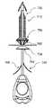
도 68 ~ 도 80은 외과 시스템을 사용하는 방법뿐만 아니라, 본 발명의 제 10 실시예에 따른 외과 시스템(910)을 도시한 것이다. 외과 시스템(910)(도 68 ~ 도 71) 및 방법(도 72 ~ 도 80)은 몇 가지를 제외하고 본원에 기술된 다른 실시예들의 것들과 동일하거나 유사하다. 이에 따라, 외과 시스템(910)은 외과 임플란트를 피술자의 피부(908)를 통해 이들의 신체 내에 임플란트하기 위한 외과 임플란트(912) 및 외과 장치(914)를 포함한다. 장치(914)는 핸들(916), 이로부터 확장하는 니들(918), 및 니들상에 맞추어진 리테이너(920)를 포함한다. 임플란트(914)는 메시(930), 원단 앵커(932) 및 메시-장력부여 조립체(예를 들면, 바로 전의 실시예에서와 같이 회전적으로 조절가능한 메시-장력부여 앵커), 및 근단 앵커(934)를 포함한다.
68-80 illustrate a
이 실시예에서, 임플란트(912)는 원단 앵커(932)와 근단 앵커(934) 사이에서 확장하고 이들에 부착된 커넥터 샤프트(985)를 추가적으로 포함한다. 커넥터 샤프트(985)는 루멘(986)을 포함하며 이를 통해 니들(918)이 임플란트 동안에 수용되어 유지된다. 도시된 것과 같은 일부 실시예들에서, 커넥터 샤프트(985)는 복수의 측방 포트들(987)을 포함하며 이를 통해 유체가 이송된다. 예를 들면, 포트들(985)은 니들(918)이 제거된 후에 주사기를 커넥터 샤프트(985)의 루멘(986) 내에 삽입함으로써 약물(예를 들면, 마취약)을 외과 부위에 이송하기 위해 사용될 수 있다. 또는, 포트들(985)은 자리에 메시의 원단 또는 근단 앵커들의 고정(혹은 적어도 고정에 기여하는)을 형성하기 위해 글루를 메시(930)에 이송하기 위해 사용될 수 있다.
In this embodiment, the
커넥터 샤프트(985)는 시간이 지남에 따라 신체 내에 흡수되는 생체흡수가능 물질로 만들어진다. 그리고, 도시된 것과 같은 실시예들에서, 특히 추가의 근단 앵커링을 제공하기 위해 에폭시를 사용할 때, 원단 앵커(934) 또한 시간이 지남에 따라 신체 내에 흡수되는 생체흡수가능 물질로 만들어진다. 이에 따라, 커넥터 샤프트(985) 및 원단 앵커(934)는 외과 절차 동안에 임플란트되고 따라서 글루가 조직에의 더 강한 본딩을 형성할 때까지 메시(930)를 위한 안정성 및 고정을 제공하며, 이어 이들은 신체 내에 흡수되고 따라서 이들을 제거하기 위해 별도의 외과 절차가 필요하지 않다. 측방 포트들(987)은 커넥터 샤프트(985)의 구조상의 이익을 희생함이 없이, 신체에 의해 덜 흡수되는 물질이 있게 되는 추가의 이익을 제공한다.
The
이 실시예의 서로 다른 구조상의 측면들을 기술하였으며, 이제 이의 사용의 상세기 기술될 것이다. 장치(914)는 니들(918)을 자리에 삽입하기 위해 사용되고, 리테이너(920)는 제거되고, 방면된 원단-앵커(932), 근단 앵커(934), 및 메시(930)는 이들의 전개된 위치들로 측방으로 뻗어나간다(도 72 ~ 도 75). 글루 앵커 스폿들을 제공할 때, 글루 디스펜서가 니들(918) 내에 삽입되고(이것이 아직 행해지지 않았다면), 이어서 글루를 니들의 글루 포트들을 통해 메시 상에 -이곳에 메시를 조직에 결합(bind)할 때까지 건조 또는 아니면 경화하는 글루 스폿들을 형성한다(도시되지 않음)- 이송하기 위해 글루 디스펜서가 작동된다. 이어, 원단 앵커의 고정 요소의 바브들(938)은 자리에 남아 있는 동안, 니들(918)이 회전되어 원단쪽으로 전진되고 이에 따라 원단 앵커(932)의 회전 요소를 회전시켜 원단쪽으로 전진시켜, 그럼으로써 메시의 원단 단부를 원단쪽으로 전진하여 메시에 장력을 부여한다(도 76 ~ 도 77). 마지막으로, 니들(918)은 이를 원단 앵커(932)로부터 방면하게 역회전되고, 니들을 피술자의 신체로부터 빼내기 위해 근단쪽으로 철회되며, 임플란트(912)는 커넥터 샤프트(985) 및 원단 앵커(934)가 신체에 의해 흡수되어 메시(930) 및 원단 앵커(932)가 슬링-유사 형태(도 78 ~ 도 79)로 자리에 장력이 부여되어 남게 될 때까지 자리에 남겨진다.
The different structural aspects of this embodiment have been described and the details of its use will now be described. The
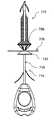
도 80 ~ 도 93은 본 발명의 제 11 실시예에 따른 외과 시스템(1010)을 도시한 것이다. 외과 시스템(1010) 및 방법은 몇 가지를 제외하고 본원에 기술된 다른 실시예들의 것들과 동일하거나 유사하다. 이에 따라, 외과 시스템(1010)은 외과 임플란트를 피술자의 피부를 통해 이들의 신체 내에 임플란트하기 위한 외과 임플란트(1012) 및 외과 장치(1014)를 포함한다. 장치(1014)는 핸들(1016), 이로부터 확장하는 니들(1018), 및 니들 상에 맞추어진 리테이너(1020)를 포함한다. 임플란트(1014)는 메시(1030) 및 원단 앵커(1032) 및 메시-장력부여 조립체(예를 들면, 바로 전의 두 실시예들에서와 같은 회전적으로 조절가능한 메시-장력부여 앵커)를 포함한다.
80-93 show a
도 80 ~ 도 84를 참조하면, 이 실시예에서, 글루-저류지 디스펜서(1080)에는 이에 부착된 핸들(1090) 및 이로부터 확장하는 글루 니들(1091)이 제공된다. 글루 니들(1091)은 동축상의 방식으로 장치 니들(1018)의 루멘 내에 수용되고, 측방 포트들(도시되지 않음)을 가지며 이를 통해 글루는 장치-니들 루멘 내로, 그리고 장치-니들 글루 포트들(도시되지 않음)을 통과하여 밖으로, 그리고 메시(1030) 상에 이송된다. 글루 니들(1091)의 원단 단부는 폐색막 설계로 되어 있고, 따라서 예를 들면 플러그(1092)에 의해 차단된다. 글루-저류지 디스펜서(1080)는 실리콘 또는 그외 다른 탄성적으로 가요성있는 물질로 만들어질 수 있다.
80-84, in this embodiment, the glue-
또한, 니들(1089)을 가진 주사기(1088)는 외과 임플란트 부위에 마취약과 같은 약물을 이송하기 위해 제공된다. 주사기 니들(1089)은 동축상의 방식으로 니들(1018)의 루멘 내에 삽입될 수 있다. 이 실시예는 메시(1030)가 자리에 접착되고 장치 니들(1018)이 측방 글루 포트들을 포함하는 실시예들에 있을 때 특히 유용하다(그러나 이것만은 아니다). 이에 따라, 외과 임플란트 부위에 니들(1018)을 삽입한 후에, 마취약을 이송하기 위해 주사기(1088)가 삽입되고 이것은 제거되고 메시-앵커링 글루를 이송하기 위해 글루 니들이 이의 자리에 삽입된다.
In addition, a
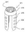
도 85 ~ 도 86을 참조하면, 이 실시예에서, 원단 앵커(1034)의 회전 요소(1071)는 수정된 설계를 갖는다. 특히, 이것은 전개되었을 때 바브들의 반경방향으로 바깥쪽으로 이동을 제한하기 위해 바브들(1038)이 나삿니가 있는 칼라 몸체(1076)로부터 확장하는 수정된 노치들(1058)을 포함한다.
85-86, in this embodiment, the
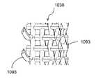
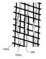
그리고 도 87 ~ 도 93을 참조하면, 메시(1030)는 이를 자리에 고정하는데 도움을 주는 앵커링 바브들을 포함할 수 있다. 도 87 ~ 도 89의 실시예에서, 메시(1030)는 메시로부터 확장하는 후크가 있는 나삿니 형태의 바브들(1093)을 포함한다. 예를 들면, 메시(1030)는 측방 나삿니들의 단부들이 후크들(1093)을 형성하는 길이방향 및 측방 모노필라멘트 나삿니들로 만들어질 수 있다. 도 90 ~ 도 91의 실시예에서, 메시(1030a)는 바브들 없이 제공되는데, 그러나 바브 봉합선들(1094a)은 메시를 통해 직조되므로 메시가 장력이 부여었을 때 봉합선들은 메시에 관하여 자리에 유지된다. 바브 봉합선들(1094a)은 일체로 형성된 바브들(1093a)을 포함하고, 공지되고 시판되는 유형의 통상의 바브 봉합선들에 의해 제공될 수 있다. 그리고, 도 92 ~ 도 93의 실시예에서, 메시(1030b)에는 통상의 바브 봉합선들에서 공통적인 동일 유형의 일체형 바브들(1093b)이 제공된다.
87 to 93, the
요약하여, 여성 피술자에 사용에서, 본원에 기술되고 첨부된 도면들에 도시된 외과 장치의 어느 것이든 본원에 기술되고 첨부된 도면들에 도시된 외과 메시들 중 하나를 자리 내에 이송하고 고정하여 앵커링하기 위해 사용될 수 있다. 장치의 니들 팁은 질 피부를 관통하여 요도 주위 영역 내로 삽입되고 속폐쇄근 또는 비뇨생식 횡경막(urogential diaphragm) 쪽으로 위쪽으로 지향된다. 일부 실시예들에서, 장치가 전진되었을 때, 국부 마취제가 니들 루멘 및 팁을 통해 이송될 수 있다. 일단 팁이 요망되는 조직(예를 들면, 근육 또는 인대)에 도달하면, 팁은 이 조직을 관통하고 외과 메시의 원단 앵커의 바브들은 고정을 위해 조직 안으로 전개된다. 니들 및 메시를 둘러싸는 리테이너 튜브는 요도 주위 영역에서 메시를 노출/전개하기 위해 분리 탭을 당김으로써 빼낸다. 손으로 질원개를 밀어 원단 앵커가 장치될 수 있다. 이어서, 니들은 신체로부터 제거된다. 메시는 의사에 의해 요망되는 바에 따라 위치되고 장력이 부여될 수 있다(이를테면 장력부여 스트링을 당기거나 나삿니가 있는 원단 앵커를 회전시킴으로써). 선택적으로, 메시를 자리에 장치하고 하나 이상의 앵커 지점들을 형성하는데 도움을 주기 위해 니들을 통해 에폭시(예를 들면, 글루 또는 그외 다른 점착성 물질)가 배출될 수 있다. 메시가 근단 앵커를 포함한다면, 근단 앵커는 자리 내로 조작되고 조직 내에(이를테면 질 피부 뒤에) 고착될 수 있다. 근단 앵커가 근단 디스크를 포함한다면, 디스크는 장치가 신체 안으로 전진될 때 질 피부 밖에 위치되고 디스크는 나중에 질로부터 제거된다(예를 들면, 생체흡수가능 봉합선들에 의해). 장력부여 스트링을 사용하는 실시예들에서, 이것은 의사가 설치 후에 필요하다면 나중에 메시 슬링을 조일 수 있도록 메시가 임플란트된 후에 질 내에 남겨질 수 있다.
In summary, in use with female subjects, any of the surgical devices described herein and shown in the accompanying drawings anchors by transporting and securing one of the surgical meshes described herein and shown in the accompanying drawings in place. Can be used to The needle tip of the device penetrates into the vaginal skin and into the area around the urethra and is directed upward towards the obstructive muscle or urogenital diaphragm. In some embodiments, when the device is advanced, a local anesthetic may be delivered through the needle lumen and the tip. Once the tip reaches the desired tissue (eg, muscle or ligament), the tip penetrates the tissue and the barbs of the distal anchor of the surgical mesh are deployed into the tissue for fixation. The retainer tube surrounding the needle and mesh is pulled out by pulling the separation tab to expose / expand the mesh in the area around the urethra. The distal anchor can be mounted by pushing the vaginal canal by hand. The needle is then removed from the body. The mesh can be positioned and tensioned as desired by the physician (such as by pulling the tensioning string or rotating the threaded far-end anchor). Optionally, epoxy (eg, glue or other tacky material) may be discharged through the needle to assist in positioning the mesh and forming one or more anchor points. If the mesh comprises a proximal anchor, the proximal anchor can be manipulated into place and secured within the tissue (such as behind the vaginal skin). If the proximal anchor comprises a proximal disk, the disk is positioned outside the vaginal skin when the device is advanced into the body and the disk is later removed from the vagina (eg, by bioabsorbable sutures). In embodiments using a tensioning string, this may be left in the vagina after the mesh has been implanted so that the surgeon may later tighten the mesh sling if necessary after installation.
이 발명은 본원에 기술 및/또는 도시된 구체적 치수들, 디바이스들, 방법들, 조건들, 또는 파라미터들로 제한되지 않으며 본원에 사용된 용어는 단지 예로서 특정 실시예들을 기술할 목적을 위한 것임이 이해되어야 한다. 이에 따라, 용어는 넓게 해석되게 의도되며 청구된 발명을 불필요하게 제한하게 의도되지 않는다. 예를 들면, 첨부된 청구항들을 포함한 명세서에 사용된 바와 같이, 단수 표현은 복수를 포함하며, "또는"이라는 용어는 "및/또는"을 의미하고, 특정 숫자값의 언급은 맥락이 달리 명백히 나타내지 않는 한 적어도 이 특정 값을 포함한다. 또한, 본원에 기술된 임의의 방법들은 기술된 단계들의 순서로 제한되게 한 것이 아니라 본원에 분명하게 달리 언급하지 않는 한, 다른 순서들로 실행될 수 있다.
This invention is not limited to the specific dimensions, devices, methods, conditions, or parameters described and / or shown herein, and the terminology used herein is for the purpose of describing particular embodiments by way of example only. This should be understood. Accordingly, the terms are intended to be interpreted broadly and not to unnecessarily limit the claimed invention. For example, as used in the specification including the appended claims, the singular forms "a", "an" and "or" refer to "and / or" and the reference to a particular numeric value is not expressly indicated otherwise in the context. Include at least this specific value unless otherwise specified. In addition, any of the methods described herein are not intended to be limited to the order of steps described, but may be executed in other orders, unless expressly stated otherwise herein.
발명이 바람직한 실시예들을 참조하여 기술되었지만, 다양한 수정, 추가 및 삭제는 다음 청구항들에 의해 정의되는 바와 같이 발명의 범위 내에 있음이 당업자들에 의해 이해될 것이다.While the invention has been described with reference to preferred embodiments, it will be understood by those skilled in the art that various modifications, additions and deletions are within the scope of the invention as defined by the following claims.
Claims (20)
Translated fromKorean메시(mesh) 및 상기 메시에 결합된 원단 앵커(distal anchor)를 포함하는 외과 임플란트; 및
상기 피술자의 신체 내에 삽입되게 개조된 니들(needle), 상기 니들이 확장하며 잡을 수 있는 핸들, 및 삽입 동안 상기 메시를 상기 니들에 유지하고 삽입 후엔 상기 메시를 제자리에 고정시키는 상기 원단 앵커와 사용하기 위해 상기 메시를 전개된 위치에 전개하기 위해 상기 니들로부터 제거될 수 있는 리테이너(retainer)를 포함하며, 상기 임플란트를 임플란트하게 동작하는 외과 디바이스를 포함하는,
요실금 치료 시스템.
A system for treating incontinence in a subject's body,
A surgical implant comprising a mesh and a distal anchor coupled to the mesh; And
For use with a needle adapted to be inserted into the subject's body, a handle that the needle expands and grips, and the distal anchor that holds the mesh to the needle during insertion and holds the mesh in place after insertion A retainer that can be removed from the needle for deploying the mesh to a deployed position, the surgical device including a surgical device for implanting the implant,
Urinary Incontinence Treatment System.
상기 메시에 장력을 부여하기 위해 상기 메시의 원단 단부를 원단쪽으로 이동하게 개조된 메시-장력부여 조립체를 더 포함하는,
요실금 치료 시스템.
The method according to claim 1,
Further comprising a mesh-tensioning assembly adapted to move the distal end of the mesh towards the distal end to tension the mesh;
Urinary Incontinence Treatment System.
상기 메시-장력부여 조립체는 상기 메시로부터 원단쪽으로 확장하고, 상기 원단 앵커에 미끄러지며 맞물리고, 상기 핸들을 향해 근단쪽으로 확장하는 장력부여 스트링을 포함하고, 상기 장력부여 스트링을 근단쪽으로 당기는 것은 상기 메시에 장력을 부여하기 위해 상기 메시를 원단쪽으로 당기는,
요실금 치료 시스템.
3. The method of claim 2,
The mesh-tensioning assembly includes a tensioning string that extends from the mesh toward the distal end, slides and engages with the distal anchor, and extends proximally toward the handle, and pulling the tensioning string toward the distal end Pulling the mesh towards the fabric to tension it,
Urinary Incontinence Treatment System.
상기 장력부여 스트링은 일방향으로 전진하는 기계식 멈추개들을 포함하고, 상기 원단 앵커는 개구를 포함하며 이를 통해 상기 장력부여 스트링이 확장하며, 상기 앵커 개구 및 상기 기계식 멈추개들은 상기 장력부여 스트링을 제자리에 선택적으로 고착시키기 위해 상기 장력부여 스트링의 일방향 전진을 제공하게 구성된,
요실금 치료 시스템.
The method of claim 3, wherein
The tensioning string includes mechanical stops advancing in one direction, the distal anchor includes an opening through which the tensioning string extends, and the anchor opening and the mechanical stops hold the tensioning string in place. Configured to provide one-way advancement of the tensioning string to selectively secure
Urinary Incontinence Treatment System.
상기 메시-장력부여 조립체는 상기 원단 앵커 내에 탑재되고, 회전 요소 및 고정 요소를 포함하며, 상기 회전 요소는 이와 함께 동시-회전하기 위해 상기 니들에 장착되고 상기 메시에 결합되는 앵커 몸체를 포함하며, 상기 고정 요소는 상기 피술자의 신체 내 자리에 맞물리고 유지되는 앵커 바브(barb)들을 포함하며, 제 1 회전 방향으로 상기 니들의 회전시, 상기 앵커 몸체는 그와 함께 회전하며, 상기 앵커 바브들은 상기 메시에 장력을 부여하기 위해 상기 앵커 몸체가 원단쪽으로 전진하게 하지 않는,
요실금 치료 시스템.
3. The method of claim 2,
The mesh-tensioning assembly is mounted in the distal anchor and includes a rotating element and a fixing element, the rotating element comprising an anchor body mounted to the needle and coupled to the mesh for co-rotating therewith; The fastening element includes anchor bars that engage and remain in place within the body of the subject, and upon rotation of the needle in a first direction of rotation, the anchor body rotates with it, and the anchor barbs are Does not allow the anchor body to advance towards the fabric to tension the mesh,
Urinary Incontinence Treatment System.
상기 앵커 몸체는 스크류 나삿니들을 포함하며, 상기 고정 요소는 칼라를 포함하고 이로부터 상기 바브들이 확장하며 상기 칼라는 상기 앵커 몸체의 상기 원단 전진을 야기하기 위해 상기 앵커 몸체 나삿니들에 결합하는 스크류 나삿니들을 갖는,
요실금 치료 시스템.
6. The method of claim 5,
The anchor body includes screw threads, wherein the securing element comprises a collar from which the barbs extend and the collar engages screw threads that engage the anchor body threads to cause the distal advancement of the anchor body. Having,
Urinary Incontinence Treatment System.
상기 앵커 몸체는 베이오넷-맞춤 슬롯(bayonet-fitting slot)을 포함하며, 상기 니들은 상기 베이오넷-맞춤 슬롯과 공조하며 상기 앵커 몸체가 제 2 반대 회전 방향이 아니라 상기 제 1 회전 방향으로 상기 니들과 함께 동시 회전하도록 개조된 베이오넷-맞춤 핀을 포함하며, 상기 제 2 회전 방향으로 회전시, 상기 니들은 상기 니들 핀이 상기 앵커-몸체 슬롯으로부터 근단쪽으로 빼내질 수 있게 상기 앵커 몸체로부터 분리하는,
요실금 치료 시스템.
6. The method of claim 5,
The anchor body includes a bayonet-fitting slot, the needle cooperates with the bayonet-fitting slot and the anchor body is in the first rotational direction rather than in a second opposite rotational direction. And a bayonet-fitting pin adapted to co-rotate with the needle, when rotating in the second direction of rotation, the needle separates from the anchor body such that the needle pin can be pulled out proximally from the anchor-body slot. ,
Urinary Incontinence Treatment System.
상기 메시는 탄성적으로 가요성있는 물질로 만들어지고, 삽입을 위한 자리에 있는 상기 리테이너와 저장된 위치로 압축(compacted)되고, 상기 리테이너의 제거시 탄성적으로 펼쳐져 전개된 위치로 측방으로 확장하는,
요실금 치료 시스템.
The method according to claim 1,
The mesh is made of an elastically flexible material, compacted to a stored position with the retainer in place for insertion, and laterally expanded to an elastically deployed and deployed position upon removal of the retainer,
Urinary Incontinence Treatment System.
상기 리테이너는, 상기 메시가 상기 저장된 위치로 압축된 채로 상기 메시 상에 맞추어지며, 상기 메시 및 니들 상에 장착된 폐쇄된 보유 위치에서 상기 리테이너가 상기 메시 및 니들로부터 제거될 수 있는 개방 방면 위치로 상기 리테이너가 조작될 수 있게 하는 파괴 지역을 포함하는 튜브에 의해 제공되는,
요실금 치료 시스템.
The method of claim 8,
The retainer is adapted to fit on the mesh with the mesh compressed to the stored position and to an open position in which the retainer can be removed from the mesh and needle in a closed retention position mounted on the mesh and needle. Provided by a tube comprising a breaking zone allowing the retainer to be operated,
Urinary Incontinence Treatment System.
상기 메시는 자리에 고정하기 위한 증가된 표면적을 제공하는 측방으로 확장가능한 기부(base)를 포함하는,
요실금 치료 시스템.
The method according to claim 1,
The mesh includes a laterally expandable base that provides increased surface area for securing in place.
Urinary Incontinence Treatment System.
상기 메시 기부는 돔-형상인,
요실금 치료 시스템.
11. The method of claim 10,
Wherein the mesh base is dome-shaped,
Urinary Incontinence Treatment System.
상기 메시 기부는 주변 자유 끝부분을 포함하고, 상기 시스템은 상기 자유 끝부분으로부터 확장하는 복수의 기부-전개 스트링들을 더 포함하며, 상기 기부-전개 스트링들을 근단쪽으로 당기는 것은 상기 기부를 상기 니들에 대항하여 압축된 저장된 위치에서 상기 돔 형상을 갖는 전개된 위치로 조작하는,
요실금 치료 시스템.
The method of claim 11,
The mesh base includes a peripheral free end, the system further includes a plurality of base-developed strings extending from the free end, and pulling the base-developed strings proximally against the needle. Manipulating the compressed position into a deployed position having the dome shape,
Urinary Incontinence Treatment System.
상기 전개된 위치에서 상기 돔-형상 기부가 순응하는 볼록 형상을 갖는 디스크 판을 포함하는 근단 앵커를 더 포함하는,
요실금 치료 시스템.
The method of claim 11,
Further comprising a proximal anchor comprising a disk plate having a convex shape to which the dome-shaped base is compliant in the deployed position,
Urinary Incontinence Treatment System.
상기 피술자의 신체 외부에 위치될 수 있고 생체흡수가능 커넥터(connector)에 의해 상기 메시의 근단 단부에 결합되는 디스크 판을 포함하는 근단 앵커를 더 포함하고, 상기 피술자의 신체에 의해 상기 커넥터가 흡수되었을 때 상기 디스크 판은 상기 피술자의 신체로부터 자유롭게 되는,
요실금 치료 시스템.
The method according to claim 1,
And a proximal anchor that may be located outside the body of the subject and including a disk plate coupled to the proximal end of the mesh by a bioabsorbable connector, the connector being absorbed by the body of the subject. When the disc plate is freed from the subject's body,
Urinary Incontinence Treatment System.
근단 앵커, 및 상기 원단 앵커와 상기 근단 앵커 사이에서 확장하는 커넥터 샤프트를 더 포함하고, 상기 커넥터 샤프트는 생체흡수가능 물질로 만들어져 상기 메시가 상기 피술자의 신체 내에 삽입된 후에 상기 생체흡수가능 커넥터가 상기 피술자의 신체에 의해 흡수되는,
요실금 치료 시스템.
The method according to claim 1,
A proximal anchor, and a connector shaft extending between the distal anchor and the proximal anchor, wherein the connector shaft is made of a bioabsorbable material such that the bioabsorbable connector is formed after the mesh is inserted into the body of the subject. Absorbed by the subject's body,
Urinary Incontinence Treatment System.
상기 니들은 루멘(lumen) 및 측방 글루(glue) 포트들을 포함하며, 상기 시스템은 글루 디스펜서(dispenser)를 더 포함하고 이로부터 글루가 상기 니들 및 상기 글루 포트들을 통과하여 상기 메시 상에 이송될 수 있는,
요실금 치료 시스템.
The method according to claim 1,
The needle includes lumen and lateral glue ports, the system further comprising a glue dispenser from which glue can pass through the needle and the glue ports onto the mesh. there is,
Urinary Incontinence Treatment System.
상기 니들은 루멘을 포함하며, 상기 시스템은 주사기를 더 포함하고 이로부터 약물이 상기 니들을 통과하여 상기 피술자의 신체로 이송될 수 있는,
요실금 치료 시스템.
The method according to claim 1,
The needle includes a lumen, the system further comprising a syringe from which drug can be passed through the needle to the subject's body,
Urinary Incontinence Treatment System.
상기 니들 및 임플란트를 상기 피술자의 신체 내에 삽입하는 단계;
상기 메시를 전개하기 위해 상기 리테이너를 상기 니들로부터 제거하는 단계;
상기 요실금을 치료하기 위해 상기 메시에 장력을 부여하는 단계;
상기 장력이 부여된 메시를 남기기 위해 상기 피술자의 신체로부터 상기 니들을 제거하는 단계를 포함하는,
방법.
A method of using the system of claim 1 for treating incontinence in a subject's body,
Inserting the needle and implant into the body of the subject;
Removing the retainer from the needle to deploy the mesh;
Tensioning the mesh to treat the incontinence;
Removing the needle from the subject's body to leave the tensioned mesh;
Way.
상기 임플란트는 메시 및 상기 메시에 결합된 원단 앵커를 포함하며, 상기 디바이스는
상기 피술자의 신체 내에 삽입되게 개조된 니들;
상기 니들이 확장하며 잡을 수 있는 핸들; 및
삽입 동안 상기 메시를 상기 니들에 유지하고 삽입 후엔 상기 메시를 제자리에 고정시키는 상기 원단 앵커와 사용하기 위해 상기 메시를 전개된 위치에 전개하기 위해 상기 니들로부터 제거될 수 있는 리테이너를 포함하는,
외과 디바이스.
A surgical device for implanting a surgical implant to treat urinary incontinence in a subject's body,
The implant includes a mesh and a fabric anchor coupled to the mesh, wherein the device is
A needle adapted to be inserted into the body of the subject;
A handle that the needle can expand and grip; And
A retainer that can be removed from the needle to deploy the mesh in its deployed position for use with the distal anchor that holds the mesh to the needle during insertion and secures the mesh in place after insertion;
Surgical device.
상기 디바이스는 상기 피술자의 신체 내에 삽입하기 위한 니들, 상기 니들이 확장하는 잡는 핸들, 및 상기 니들에 장착하는 리테이너를 포함하며, 상기 임플란트는
상기 피술자의 신체 내에서 자리에 고정하는 원단 앵커; 및
상기 원단 앵커에 결합되고, 상기 피술자의 신체 내에 삽입 동안 상기 리테이너에 의해 상기 니들로 유지되고, 상기 리테이너의 삽입 및 제거 후에 상기 메시를 제자리에 고정하는 상기 원단 앵커와 사용하기 위해 전개된 위치로 측방으로 확장될 수 있는 메시를 포함하는,
외과 임플란트.
A surgical implant for implanting by a surgical device to treat incontinence in a subject's body,
The device includes a needle for insertion into the body of the subject, a holding handle on which the needle extends, and a retainer mounted to the needle, wherein the implant is
A fabric anchor fixed in place within the body of the subject; And
Coupled to the distal anchor, held by the retainer by the retainer during insertion into the subject's body, and laterally in a deployed position for use with the distal anchor securing the mesh in place after insertion and removal of the retainer. Containing meshes that can be expanded into,
Surgical implants.
Applications Claiming Priority (5)
| Application Number | Priority Date | Filing Date | Title |
|---|---|---|---|
| US201161449078P | 2011-03-03 | 2011-03-03 | |
| US61/449,078 | 2011-03-03 | ||
| US201261593353P | 2012-02-01 | 2012-02-01 | |
| US61/593,353 | 2012-02-01 | ||
| PCT/US2012/027727WO2012119145A1 (en) | 2011-03-03 | 2012-03-05 | Systems and methods for treating urinary incontinence |
Publications (1)
| Publication Number | Publication Date |
|---|---|
| KR20140043889Atrue KR20140043889A (en) | 2014-04-11 |
Family
ID=46758324
Family Applications (1)
| Application Number | Title | Priority Date | Filing Date |
|---|---|---|---|
| KR1020137026126AWithdrawnKR20140043889A (en) | 2011-03-03 | 2012-03-05 | Systems and methods for treating urinary incontinence |
Country Status (8)
| Country | Link |
|---|---|
| US (1) | US20120259168A1 (en) |
| EP (1) | EP2680786A4 (en) |
| JP (1) | JP2014514008A (en) |
| KR (1) | KR20140043889A (en) |
| CN (1) | CN103561681B (en) |
| AU (1) | AU2012223152A1 (en) |
| CA (1) | CA2828981A1 (en) |
| WO (1) | WO2012119145A1 (en) |
Families Citing this family (12)
| Publication number | Priority date | Publication date | Assignee | Title |
|---|---|---|---|---|
| US20060167481A1 (en)* | 2005-01-25 | 2006-07-27 | Esophyx, Inc. | Slitted tissue fixation devices and assemblies for deploying the same |
| US8720446B2 (en)* | 2010-06-04 | 2014-05-13 | Coloplast A/S | Sacrocolpopexy support and method of implantation |
| US20140257029A1 (en)* | 2013-03-11 | 2014-09-11 | Boston Scientific Scimed, Inc. | Medical device and method for injecting a fluid |
| US10039626B2 (en) | 2013-03-11 | 2018-08-07 | Boston Scientific Scimed, Inc. | Incontinence sling, delivery device and method of use |
| KR101534814B1 (en)* | 2015-03-05 | 2015-07-08 | 심길섭 | Mesh assembly |
| EP3324882B1 (en)* | 2015-07-21 | 2023-10-25 | Tela Bio, Inc. | Compliance control stitching in substrate materials |
| ES3029211T3 (en) | 2017-01-16 | 2025-06-23 | Coloplast As | Sacrocolpopexy support |
| CN117481866A (en)* | 2017-12-27 | 2024-02-02 | 苏州优迈医疗器械有限公司 | Device for adjusting and fixing tension of surgical mesh and surgical application of device |
| US11389157B2 (en)* | 2020-05-27 | 2022-07-19 | Mentor Worldwide Llc | Wound closure assemblies and methods for approximating tissue |
| WO2022022821A1 (en)* | 2020-07-29 | 2022-02-03 | Promedon Gmbh | A human implant arrangement for constricting a human tissue structure |
| CN115737194A (en)* | 2022-11-29 | 2023-03-07 | 苏州优迈医疗器械有限公司 | Urinary incontinence suspension belt and application thereof |
| CN116849741A (en)* | 2023-08-09 | 2023-10-10 | 浙江科惠医疗器械股份有限公司 | An implanter that can simultaneously implant bone anchors, patches and sutures |
Family Cites Families (29)
| Publication number | Priority date | Publication date | Assignee | Title |
|---|---|---|---|---|
| US5300106A (en)* | 1991-06-07 | 1994-04-05 | Cardiac Pacemakers, Inc. | Insertion and tunneling tool for a subcutaneous wire patch electrode |
| US5957953A (en)* | 1996-02-16 | 1999-09-28 | Smith & Nephew, Inc. | Expandable suture anchor |
| US6984241B2 (en)* | 1996-09-13 | 2006-01-10 | Tendon Technology, Ltd. | Apparatus and methods for tendon or ligament repair |
| ATE371409T1 (en)* | 1998-05-21 | 2007-09-15 | Christopher J Walshe | SYSTEM FOR FIXING TISSUE |
| US6042536A (en)* | 1998-08-13 | 2000-03-28 | Contimed, Inc. | Bladder sling |
| US7410460B2 (en)* | 1998-11-23 | 2008-08-12 | Benderev Theodore V | System for securing sutures, grafts and soft tissue to bone and periosteum |
| ES2322551T3 (en)* | 2000-11-20 | 2009-06-23 | Ethicon, Inc. | SURGICAL INSTRUMENT FOR THE TREATMENT OF FEMALE URINARY INCONTINENCE. |
| GB0108088D0 (en)* | 2001-03-30 | 2001-05-23 | Browning Healthcare Ltd | Surgical implant |
| FR2831051B1 (en)* | 2001-10-22 | 2004-07-30 | Johnson & Johnson Internat | MINI SUPPORT UNDER URETHRO-CERVICAL |
| US6911003B2 (en)* | 2002-03-07 | 2005-06-28 | Ams Research Corporation | Transobturator surgical articles and methods |
| CA2492630C (en)* | 2002-08-02 | 2009-01-13 | C.R. Bard, Inc. | Self anchoring sling and introducer system |
| US7235042B2 (en)* | 2003-09-16 | 2007-06-26 | Acorn Cardiovascular, Inc. | Apparatus and method for applying cardiac support device |
| WO2005067802A1 (en)* | 2004-01-20 | 2005-07-28 | Van Der Weiden Robertus Matthe | Assembly and method for attaching particularly a vagina to a spine |
| WO2006049725A2 (en)* | 2004-03-23 | 2006-05-11 | Minimus Surgical Systems | Surgical systems and devices to enhance gastric restriction therapies |
| EP3087949B1 (en)* | 2004-06-14 | 2018-07-25 | Boston Scientific Limited | System relating to implantable supportive slings |
| EP1816979B1 (en)* | 2004-10-05 | 2012-04-18 | AMS Research Corporation | Device for supporting vaginal cuff |
| US20060149264A1 (en)* | 2004-12-20 | 2006-07-06 | Castaneda Javier E | Screw locking systems for bone plates |
| AU2006210494B2 (en)* | 2005-02-04 | 2011-01-06 | Ams Research Corporation | Needle design for male transobturator sling |
| CA2908132C (en)* | 2006-02-16 | 2018-12-11 | Ams Research Corporation | Surgical articles and methods for treating pelvic conditions |
| CA2654294C (en)* | 2006-06-22 | 2016-09-20 | Ams Research Corporation | Adjustable tension incontinence sling assemblies |
| CN101534746A (en)* | 2006-07-25 | 2009-09-16 | Ams研究公司 | Surgical articles and methods for treating pelvic conditions |
| CA2734026C (en)* | 2007-01-02 | 2015-06-09 | Boston Scientific Scimed, Inc. | Reinforced mesh for retropubic implants |
| EP2194913A1 (en)* | 2007-09-21 | 2010-06-16 | AMS Research Corporation | Pelvic floor treatments and related tools and implants |
| EP2247252A4 (en)* | 2008-02-14 | 2015-01-28 | Robert C Brown | Method for treating stress urinary incontinence and symptomatic pelvic relaxation |
| US8585579B2 (en)* | 2009-02-05 | 2013-11-19 | Coloplast A/S | Implantable anatomical support |
| US8720446B2 (en)* | 2010-06-04 | 2014-05-13 | Coloplast A/S | Sacrocolpopexy support and method of implantation |
| US8585578B2 (en)* | 2009-02-05 | 2013-11-19 | Coloplast A/S | Implantable devices, tools and methods for anatomical support |
| US20100292733A1 (en)* | 2009-05-12 | 2010-11-18 | Foundry Newco Xi, Inc. | Knotless suture anchor and methods of use |
| US8109867B2 (en)* | 2009-05-28 | 2012-02-07 | Rosenblatt Associates, Llc | Tubular mesh for sacrocolpopexy and related procedures |
- 2012
- 2012-03-05KRKR1020137026126Apatent/KR20140043889A/ennot_activeWithdrawn
- 2012-03-05JPJP2013556673Apatent/JP2014514008A/enactivePending
- 2012-03-05AUAU2012223152Apatent/AU2012223152A1/ennot_activeAbandoned
- 2012-03-05EPEP12752256.3Apatent/EP2680786A4/ennot_activeWithdrawn
- 2012-03-05USUS13/412,225patent/US20120259168A1/ennot_activeAbandoned
- 2012-03-05CNCN201280021752.5Apatent/CN103561681B/ennot_activeExpired - Fee Related
- 2012-03-05WOPCT/US2012/027727patent/WO2012119145A1/enactiveApplication Filing
- 2012-03-05CACA2828981Apatent/CA2828981A1/ennot_activeAbandoned
Also Published As
| Publication number | Publication date |
|---|---|
| CN103561681B (en) | 2016-01-13 |
| AU2012223152A1 (en) | 2013-10-24 |
| WO2012119145A1 (en) | 2012-09-07 |
| JP2014514008A (en) | 2014-06-19 |
| EP2680786A4 (en) | 2015-04-15 |
| AU2012223152A2 (en) | 2014-01-30 |
| US20120259168A1 (en) | 2012-10-11 |
| EP2680786A1 (en) | 2014-01-08 |
| CN103561681A (en) | 2014-02-05 |
| CA2828981A1 (en) | 2012-09-07 |
Similar Documents
| Publication | Publication Date | Title |
|---|---|---|
| KR20140043889A (en) | Systems and methods for treating urinary incontinence | |
| ES2688601T3 (en) | Compressive fabric anchor sets | |
| US11844510B2 (en) | All-suture suture anchor systems and methods | |
| CA2557722C (en) | Methods and devices for reducing hollow organ volume | |
| US9241710B2 (en) | Surgical fasteners and fastening devices | |
| US20150018876A1 (en) | Low profile tissue anchors, tissue anchor systems, and methods for their delivery and use | |
| US8961539B2 (en) | Endoscopic implant system and method | |
| AU2009302169A1 (en) | Termination devices and related methods | |
| CN104053406A (en) | tissue repair components | |
| TW201225997A (en) | Assembly and method for stabilizing a percutaneous cable | |
| US20210275290A1 (en) | Soft suture staple system with tethered anchoring mechanism | |
| ES2864169T3 (en) | Anchor for implantation in a body |
Legal Events
| Date | Code | Title | Description |
|---|---|---|---|
| PA0105 | International application | Patent event date:20131002 Patent event code:PA01051R01D Comment text:International Patent Application | |
| PG1501 | Laying open of application | ||
| PC1203 | Withdrawal of no request for examination | ||
| WITN | Application deemed withdrawn, e.g. because no request for examination was filed or no examination fee was paid |