KR20140043159A - Line tracking with automatic model initialization by graph matching and cycle detection - Google Patents
Line tracking with automatic model initialization by graph matching and cycle detectionDownload PDFInfo
- Publication number
- KR20140043159A KR20140043159AKR1020147005465AKR20147005465AKR20140043159AKR 20140043159 AKR20140043159 AKR 20140043159AKR 1020147005465 AKR1020147005465 AKR 1020147005465AKR 20147005465 AKR20147005465 AKR 20147005465AKR 20140043159 AKR20140043159 AKR 20140043159A
- Authority
- KR
- South Korea
- Prior art keywords
- lines
- group
- subgraph
- interest
- forming
- Prior art date
- Legal status (The legal status is an assumption and is not a legal conclusion. Google has not performed a legal analysis and makes no representation as to the accuracy of the status listed.)
- Ceased
Links
Images


Classifications
- G—PHYSICS
- G06—COMPUTING OR CALCULATING; COUNTING
- G06T—IMAGE DATA PROCESSING OR GENERATION, IN GENERAL
- G06T7/00—Image analysis
- G06T7/20—Analysis of motion
- G—PHYSICS
- G06—COMPUTING OR CALCULATING; COUNTING
- G06T—IMAGE DATA PROCESSING OR GENERATION, IN GENERAL
- G06T7/00—Image analysis
- G06T7/20—Analysis of motion
- G06T7/246—Analysis of motion using feature-based methods, e.g. the tracking of corners or segments
- G06T7/251—Analysis of motion using feature-based methods, e.g. the tracking of corners or segments involving models
- G—PHYSICS
- G06—COMPUTING OR CALCULATING; COUNTING
- G06T—IMAGE DATA PROCESSING OR GENERATION, IN GENERAL
- G06T2207/00—Indexing scheme for image analysis or image enhancement
- G06T2207/10—Image acquisition modality
- G06T2207/10016—Video; Image sequence
Landscapes
- Engineering & Computer Science (AREA)
- Multimedia (AREA)
- Computer Vision & Pattern Recognition (AREA)
- Physics & Mathematics (AREA)
- General Physics & Mathematics (AREA)
- Theoretical Computer Science (AREA)
- Image Analysis (AREA)
- Studio Devices (AREA)
Abstract
Translated fromKoreanDescription
Translated fromKorean관련 출원(들)에 대한 상호참조Cross-reference to related application (s)
본 출원은 "Line Tracking With Automatic Model Initialization by Graph Matching and Cycle Detection" 의 명칭으로 2012년 3월 9일자로 출원된 미국 특허출원 제13/416,721호를 우선권 주장하고, 이 출원은, 차례로, "Line Tracking With Automatic Model Initialization by Graph Matching and Cycle Detection" 의 명칭으로 2011년 9월 2일자로 출원된 미국 가특허출원 제61/530,907호에 대해 35 USC 119 하에서 우선권 주장하며, 이 출원들 양자는 본 발명의 양수인에게 양도되고 본 명세서에 참조로 통합된다.This application claims priority to US patent application Ser. No. 13 / 416,721, filed Mar. 9, 2012, entitled “Line Tracking With Automatic Model Initialization by Graph Matching and Cycle Detection,” which in turn is “Line Tracking With Automatic Model Initialization by Graph Matching and Cycle Detection”. Tracking with Automatic Model Initialization by Graph Matching and Cycle Detection, US Patent Application Ser. No. 61 / 530,907, filed Sep. 2, 2011, claims priority under 35 USC 119, both of which are incorporated herein by reference. Is assigned to the assignee of and incorporated herein by reference.
본 명세서에 설명된 청구물의 실시형태들은 일반적으로 포지션 및 트래킹에 관한 것으로서, 더 상세하게는, 비전 기반 트래킹에 관한 것이다.Embodiments of the claims described herein generally relate to position and tracking and, more particularly, to vision based tracking.
비전 기반 트래킹 시스템들은 레퍼런스 이미지에 대한 카메라의 포지션 및 배향 (포즈) 을 추정하는데 사용된다. 레퍼런스 이미지는 통상적으로, 카메라 또는 다른 카메라들에 의해 캡처된 실세계 환경의 일부의 다중의 이미지들 (종종 프레임들로서 지칭됨) 에 기초한다. 결정된 카메라의 포즈를 사용하여, 증강 현실과 같지만 이에 한정되지 않는 어플리케이션들이 수행될 수도 있다. 정확하고 강인한 트래킹은, 가상 증강과 실세계 환경 간의 기밀한 등록을 가능케 하기 때문에, 증강 현실과 같은 어플리케이션에 대해 특히 중요하다.Vision-based tracking systems are used to estimate the position and orientation (pose) of the camera relative to the reference image. The reference image is typically based on multiple images (often referred to as frames) of a portion of the real world environment captured by the camera or other cameras. Using the determined pose of the camera, applications such as but not limited to augmented reality may be performed. Accurate and robust tracking is particularly important for applications such as augmented reality because it enables confidential registration between virtual augmentation and real world environments.
비전 기반 트래킹의 일 타입은 이미지에 있어서 라인들을 검출하고 트래킹하는 것에 기초한다. 라인 트래킹 알고리즘들은, 예를 들어, 트래킹되는 오브젝트가 매우 작은 텍스처를 갖는 경우에 유용하다. 하지만, 종래의 라인 트래킹은, 다수의 증강 현실 어플리케이션들에 대해 요구되는 강인성이 결여된다. 따라서, 라인 트래킹에 있어서의 개선이 바람직하다.One type of vision based tracking is based on detecting and tracking lines in an image. Line tracking algorithms are useful, for example, when the object being tracked has a very small texture. However, conventional line tracking lacks the robustness required for many augmented reality applications. Therefore, improvement in line tracking is desirable.
모바일 플랫폼에 있어서의 비전 기반 트래킹 시스템은 검출된 라인들의 그룹들을 이용하여 오브젝트들을 트래킹한다. 트래킹 시스템은 트래킹될 오브젝트의 캡처된 이미지에서의 라인들을 검출한다. 라인들의 그룹들은 검출된 라인들로부터 형성된다. 라인들의 그룹들은 검출된 라인들의 교차 포인트들을 산출하고, 연결된 라인들을 식별하기 위해 교차 포인트들을 이용함으로써 형성될 수도 있으며, 여기서, 라인들의 그룹들은 연결된 라인들을 이용하여 형성된다. 검출된 라인들의 그래프가 구성되고 교차 포인트들이 식별될 수도 있다. 관심있는 서브그래프들이 연결들을 이용하여 생성되고, 라인들의 그룹이 관심있는 서브그래프들로 형성된다. 일단 라인들의 그룹들이 형성되면, 라인들의 그룹들은, 예를 들어, 오브젝트의 현재 이미지에서의 라인들의 그룹들을 오브젝트의 이전 이미지에서의 라인들의 그룹들과 비교함으로써, 오브젝트를 트래킹하는데 사용된다.The vision based tracking system in the mobile platform tracks the objects using the groups of detected lines. The tracking system detects the lines in the captured image of the object to be tracked. Groups of lines are formed from the detected lines. Groups of lines may be formed by calculating intersection points of detected lines and using intersection points to identify connected lines, where groups of lines are formed using connected lines. A graph of detected lines is constructed and intersection points may be identified. Subgraphs of interest are created using the connections, and a group of lines is formed of subgraphs of interest. Once groups of lines are formed, the groups of lines are used to track the object, for example, by comparing the groups of lines in the current image of the object with the groups of lines in the previous image of the object.
일 실시형태에 있어서, 일 방법은 트래킹될 오브젝트의 이미지를 캡처하는 단계; 오브젝트의 이미지에 있어서 복수의 라인들을 검출하는 단계; 복수의 라인들로부터 라인들의 그룹을 형성하는 단계; 및 라인들의 그룹을 이용하여 오브젝트를 트래킹하는 단계를 포함한다.In one embodiment, a method includes capturing an image of an object to be tracked; Detecting a plurality of lines in the image of the object; Forming a group of lines from the plurality of lines; And tracking the object using the group of lines.
일 실시형태에 있어서, 일 장치는 카메라; 및 카메라에 접속된 프로세서를 포함하고, 프로세서는 트래킹될 오브젝트의 카메라에 의해 캡처된 이미지에 있어서 복수의 라인들을 검출하고, 복수의 라인들로부터 라인들의 그룹을 형성하며, 그리고 라인들의 그룹을 이용하여 오브젝트를 트래킹하도록 구성된다.In one embodiment, an apparatus comprises a camera; And a processor connected to the camera, the processor detecting a plurality of lines in the image captured by the camera of the object to be tracked, forming a group of lines from the plurality of lines, and using the group of lines Configured to track the object.
일 실시형태에 있어서, 일 장치는 트래킹될 오브젝트의 이미지를 캡처하는 수단; 오브젝트의 이미지에 있어서 복수의 라인들을 검출하는 수단; 복수의 라인들로부터 라인들의 그룹을 형성하는 수단; 및 라인들의 그룹을 이용하여 오브젝트를 트래킹하는 수단을 포함한다.In one embodiment, an apparatus includes means for capturing an image of an object to be tracked; Means for detecting a plurality of lines in an image of the object; Means for forming a group of lines from the plurality of lines; And means for tracking the object using the group of lines.
일 실시형태에 있어서, 저장된 프로그램 코드를 포함하는 비-일시적인 컴퓨터 판독가능 매체는 트래킹될 오브젝트의 이미지를 캡처하기 위한 프로그램 코드; 오브젝트의 이미지에 있어서 복수의 라인들을 검출하기 위한 프로그램 코드; 복수의 라인들로부터 라인들의 그룹을 형성하기 위한 프로그램 코드; 및 라인들의 그룹을 이용하여 오브젝트를 트래킹하기 위한 프로그램 코드를 포함한다.In one embodiment, a non-transitory computer readable medium comprising stored program code includes: program code for capturing an image of an object to be tracked; Program code for detecting a plurality of lines in an image of the object; Program code for forming a group of lines from the plurality of lines; And program code for tracking the object using the group of lines.
도 1a 및 도 1b 는, 각각, 본 명세서에서 설명되는 바와 같은 강인한 방식으로 비전 기반 라인 트래킹을 수행하는 것이 가능한 모바일 플랫폼의 전면측 및 후면측을 도시한 것이다.
도 2 는 비전 기반 트래킹 유닛의 2개의 메인 컴포넌트들을 도시한 것이다.
도 3 은 비전 기반 트래킹 유닛에서의 라인 검출의 컴포넌트들을 도시한 것이다.
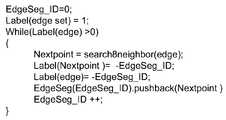
도 4 는 에지 링킹 알고리즘을 도시한 것이다.
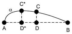
도 5 는 라인 피팅에서 사용된 라인 근사화를 도시한 것이다.
도 6 은 비전 기반 트래킹 유닛에서의 라인 트래킹을 도시한 것이다.
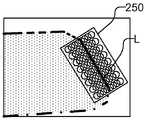
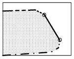
도 7a, 도 7b, 및 도 7c 는, 라인 피팅을 위해 프로세싱되는 다수의 에지들을 포함하는 이미지를 도시한 것이다.
도 8 은 라인들의 그룹을 이용하여 오브젝트들을 트래킹하는 방법을 도시한 플로우이다.
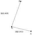
도 9 는 3개의 포인트들 간의 라인들을 도시한 것이다.
도 10 은 정점들 (A, B, C, 및 D) 간의 라인들을 도시한 것이다.
도 11 은 사이클 검출 및 분할을 도시한 것이다.
도 12a 및 도 12b 는, 각각, 에지들을 나타낸 오리지널 그래프 및 추출된 사이클들을 나타낸 그래프를 도시한 것이다.
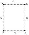
도 13 은 도 10 과 유사한 정점들 (A, B, C, 및 D) 간의 라인들을 도시하지만, 에지들 (e1-e4) 을 라벨링한다.
도 14 는 매트릭스 표현에 기초한 사이클 검출의 일 예로서 4개의 정점들 간의 5개의 라인들을 도시한 것이다.
도 15 는 도 14 에 도시된 그래프를 분할하는 것을 도시한 것이다.
도 16 은 라인들의 그룹을 이용하여 오브젝트들을 트래킹하는 것이 가능한 모바일 플랫폼의 블록 다이어그램이다.1A and 1B illustrate the front side and back side of a mobile platform capable of performing vision based line tracking in a robust manner as described herein, respectively.
2 shows two main components of a vision based tracking unit.
3 illustrates components of line detection in a vision based tracking unit.
4 illustrates an edge linking algorithm.
5 shows the line approximation used in line fitting.
6 illustrates line tracking in a vision based tracking unit.
7A, 7B, and 7C illustrate an image that includes multiple edges that are processed for line fitting.
8 is a flow diagram illustrating a method of tracking objects using a group of lines.
9 shows lines between three points.
10 shows the lines between vertices A, B, C, and D. FIG.
11 illustrates cycle detection and division.
12A and 12B show an original graph showing edges and a graph showing extracted cycles, respectively.
FIG. 13 shows lines between vertices A, B, C, and D similar to FIG. 10, but labels the edges e1- e4 .
14 shows five lines between four vertices as an example of cycle detection based on a matrix representation.
FIG. 15 illustrates dividing the graph shown in FIG. 14.
16 is a block diagram of a mobile platform capable of tracking objects using a group of lines.
도 1a 및 도 1b 는, 각각, 본 명세서에서 설명되는 바와 같은 강인한 방식으로 비전 기반 라인 트래킹을 수행하는 것이 가능한 모바일 플랫폼 (100) 의 전면측 및 후면측을 도시한 것이다. 모바일 플랫폼 (100) 은 하우징 (101), 터치 스크린 디스플레이일 수도 있는 디스플레이 (102)뿐 아니라 스피커 (104) 및 마이크로폰 (106) 을 포함하는 것으로서 도시된다. 모바일 플랫폼 (100) 은 비전 기반 트래킹 유닛 (112) 에 대한 환경을 이미징하기 위한 카메라 (110) 를 더 포함한다. 비전 기반 트래킹 유닛 (112) 은 라인들의 그룹들을 트래킹한다. 대부분의 종래의 라인 트래킹 시스템들의 단점들 중 하나는 라인들이 독립적으로 트래킹된다는 것이며, 이는 프로세스의 강인성을 제한한다. 라인들의 그룹들을 트래킹하는 것은 트래킹 프로세스의 강인성을 개선시킨다. 부가적으로, 비전 기반 트래킹 유닛 (112) 은 자동 모델 초기화를 이용하여 트래킹될 라인들의 그룹들을 획득할 수도 있다. 자동 모델 초기화는, 예를 들어, 그래프 매칭 및 사이클 검출일 수도 있다. 비전 기반 트래킹 유닛 (112) 은 레퍼런스 프리 및 레퍼런스 기반 트래킹으로 사용될 수도 있다.1A and 1B illustrate the front side and back side of the
본 명세서에서 사용된 바와 같이, 모바일 플랫폼은 셀룰러 또는 다른 무선 통신 디바이스, 퍼스널 통신 시스템 (PCS) 디바이스, 퍼스널 네비게이션 디바이스 (PND), 퍼스널 정보 매니저 (PIM), 퍼스널 디지털 보조기 (PDA), 또는 다른 적절한 모바일 디바이스와 같은 임의의 휴대용 전자 디바이스를 지칭한다. 모바일 플랫폼은 네비게이션 포지셔닝 신호들과 같은 무선 통신 및/또는 네비게이션 신호들을 수신하는 것이 가능할 수도 있다. 용어 "모바일 플랫폼" 은 또한, 위성 신호 수신, 보조 데이터 수신, 및/또는 포지션 관련 프로세싱이 그 디바이스에서 또는 PND 에서 발생하는지 여부에 무관하게, 예를 들어, 단거리 무선, 적외선, 유선 접속, 또는 다른 접속에 의한 퍼스널 네비게이션 디바이스 (PND) 와 통신하는 디바이스들을 포함하도록 의도된다. 또한, "모바일 플랫폼" 은, 비전 기반 트래킹이 가능한 무선 통신 디바이스들, 컴퓨터들, 랩탑들, 태블릿 컴퓨터들 등을 포함한 모든 전자 디바이스들을 포함하도록 의도된다.As used herein, a mobile platform may be a cellular or other wireless communication device, personal communication system (PCS) device, personal navigation device (PND), personal information manager (PIM), personal digital assistant (PDA), or other suitable. It refers to any portable electronic device, such as a mobile device. The mobile platform may be capable of receiving wireless communication and / or navigation signals, such as navigation positioning signals. The term “mobile platform” also refers to, for example, short range wireless, infrared, wired connection, or other, regardless of whether satellite signal reception, auxiliary data reception, and / or position related processing occurs at the device or at the PND. It is intended to include devices in communication with a personal navigation device (PND) by connection. Also, "mobile platform" is intended to include all electronic devices, including wireless communication devices, computers, laptops, tablet computers, etc., capable of vision-based tracking.
도 2 에 의해 도시된 바와 같이, 비전 기반 트래킹 유닛 (112) 은 2개의 메인 컴포넌트들: 즉, 라인 검출 (200) 및 트래킹 (220) 을 포함한다. 도 2 및 도 3 에 도시된 바와 같이, 라인 검출 (200) 은 초기화 (202), 에지 검출 (204), 에지 링킹 (206), 및 라인 세그먼트 피팅 (208) 을 포함한다. 도 2 및 도 6 에 도시된 바와 같이, 트래킹 (220) 은, 도 2 에 도시된 바와 같이, 로컬 탐색의 수행, 에지 세트의 분포의 산출 및 프레임 투 프레임 트래킹을 포함한다. 라인 검출 (200) 에서의 초기화 (202) 는 트래킹될 오브젝트의 입력 이미지를 제공하는 것을 포함한다. 에지 검출 (204) 은, 예를 들어, 당업계에 널리 공지된 캐니 에지 검출기, 소벨 에지 검출기, 프리윗 에지 검출기, 또는 다른 적절한 에지 검출기에 의해 수행될 수도 있다. 그 후, 비-최대 억제를 통한 에지 박형화가, 에지 포인트들의 세트를 에지 맵의 형태로 생성하기 위해 수행된다. 그 후, 에지 링킹 (206) 이 수행되어, 에지 세그먼트들을 발생시킨다. 예로써, 도 4 는, 사용될 수도 있는 에지 링킹 알고리즘을 도시한 것이다. 에지 링킹 알고리즘은, 로컬 이웃에서 에지 맵을 조사하고 이 영역에서 다른 에지 포인트들을 식별함으로써, 에지 맵에서 각각의 에지 포인트를 조사하고, 그 포인트를 에지 세그먼트 ID 로 라벨링한다. 예로써, 로컬 이웃은 에지 포인트 주위의 8×8 픽셀 영역일 수도 있다. 그 후, 라인 세그먼트 피팅 (208) 이, 복수의 라인 세그먼트들에 의해 에지를 표현하기 위해 수행된다. 예로써, 도 5 는 포인트들 (A 내지 B) 간의 곡선 (α) 에 대한 라인 피팅을 도시한 것이다. 포인트들 (A 및 B) 간의 곡선 (α) 상의 각각의 포인트 (C) 에 대해, 알고리즘은 라인 (CD) 가 라인 (AB) 에 수직하도록, 즉, <AB, CD> = 0 이도록 라인 (AB) 상의 포인트 (D) 를 먼저 식별한다. 거리 (CD) 가 노트되고, 최대 거리 (CD) 를 발생시키는 포인트 (C) 가 식별되어, 도 5 에 포인트 (C*) 에 의해 표현된다. 최대 거리, 즉, 포인트 (C*) 와 대응하는 포인트 (D*) 간의 최대 거리가 적절히 사전 선택된 임계치 (T) 미만이면, 라인 (AB) 은 곡선 (α) 의 양호한 근사로 고려된다. 한편, 최대 거리가 임계치 (T) 이상이면, 알고리즘은 개별 라인들 (AC* 및 C*B) 각각에 대해 반복된다.As shown by FIG. 2, the vision based
도 6 은 비전 기반 트래킹 유닛에서의 라인 트래킹 (220) 을 도시한 것이다. 이전 프레임 상의 라인 검출 (200) 단계에서 식별된 각각의 라인 세그먼트에 대해, 로컬 탐색 영역이 현재 프레임에서 식별된다 (222). 도 7a 는 에지 영역 (L) 주위의 8×8 픽셀 영역일 수도 있는 로컬 탐색 영역 (250) 을 갖는 다수의 에지들을 포함하는 이미지를 도시한 것이다. 다음, 로컬 탐색 영역에서의 각각의 픽셀에 대해, 구배 (gradient) 의 크기 및 배향이 현재 이미지에 기초하여 산출된다 (224). 일 실시형태에 있어서, 캐니 연산자가 이미지 구배들을 산출하기 위해 이용될 수도 있다. 대안적으로, 소벨 또는 프리윗 커널들, 또는 등가 구배 산출 커널들이 이미지 구배들을 산출하기 위해 이용될 수도 있다. 비-최대 억제가 구배 맵에 대해 부가적으로 수행될 수도 있다. 구배 배향들 및 구배 크기들의 분포가 산출되고, 라인 세그먼트 (L) 와 유사한 분포를 갖는 에지 포인트들의 서브세트를 탐색 영역에서 식별하기 위해 사용된다. 선형 회귀 기술들이, 도 7b 에 도시된 바와 같이, 에지 포인트들의 선택된 서브세트의 지배적인 방향을 계산하여 최근접 에지 후보를 선택하기 위해 채용될 수도 있다 (226). 일 실시형태에 있어서, PCA (Principal Component Analysis) 가 에지 포인트들의 서브세트의 지배적인 방향을 식별하기 위해 채용될 수도 있다. 도 7c 에 도시된 바와 같이, 라인 세그먼트는 현재 프레임에 있어서 에지 포인트들의 서브세트에 대해 피팅되고 (228), 라인 세그먼트의 그 파라미터들은 피팅 에러를 최소화하기 위해 추가로 정세화된다 (230).6 illustrates line tracking 220 in a vision based tracking unit. For each line segment identified in the
라인 트래킹 시스템의 강인성을 증가시키기 위해, 라인들은 더 우수한 디스크립션을 형성하기 위해 그룹들로 결합되고, 그 후, 이들이 트래킹될 수 있다. 도 8 은 라인들의 그룹을 이용하여 오브젝트들을 트래킹하는 방법을 도시한 것이다. 도 8 에 도시된 바와 같이, 트래킹될 오브젝트의 이미지가, 예를 들어, 모바일 플랫폼 (100) 에 의해 캡처된 이미지들 또는 비디오의 복수의 프레임들 중 하나로서 캡처된다 (302). 오브젝트의 이미지에 있어서의 복수의 라인들이, 예를 들어, 도 3 에서 상기 설명된 바와 같이 또는 임의의 다른 요구된 방식으로 검출된다 (304). 라인들의 그룹이 복수의 라인들로부터 형성되고 (306), 라인들의 그룹은, 예를 들어, 도 6 에서 상기 설명된 바와 같이 또는 임의의 다른 요구된 방식으로 일 프레임으로부터 다음 프레임으로 오브젝트를 트래킹하는데 사용된다 (308). 라인들의 그룹은, 예를 들어, 정사각형, 직사각형, 또는 사이클과 같은 폐쇄된 도형에 있어서 연결된 라인들일 수도 있다.In order to increase the robustness of the line tracking system, the lines can be combined into groups to form a better description and then they can be tracked. 8 illustrates a method of tracking objects using a group of lines. As shown in FIG. 8, an image of the object to be tracked is captured 302, for example, as one of a plurality of frames of images or video captured by the
라인들의 그룹들은, 복수의 라인들의 모든 교차 포인트들을 산출하고, 연결된 라인들을 식별하기 위해 교차 포인트들을 이용함으로써 형성될 수도 있다 (306). 예를 들어, 라인들의 그룹은, 복수의 라인들로부터 그래프를 구성하고; 복수의 라인들의 모든 교차 포인트들을 산출하며; 그리고 교차 포인트들의 각 쌍 사이의 연결들을 이용하여 관심있는 서브그래프를 생성함으로써 형성될 수도 있다. 일단 교차 포인트들이 식별되면, 라인들의 세트에 대한 그래프 (G) 는 다음과 같이 구성될 수도 있다:Groups of lines may be formed by calculating all intersection points of the plurality of lines and using the intersection points to identify connected lines (306). For example, a group of lines constitutes a graph from a plurality of lines; Calculate all intersection points of the plurality of lines; And may be formed by generating a subgraph of interest using the connections between each pair of intersection points. Once the intersection points are identified, the graph G for the set of lines may be constructed as follows:

여기서, T 는 적절히 선택된 임계치이다. 예로써, 도 9 는 라인 (A,B) 및 라인 (A,C) 를 갖는 포인트들 (A, B, 및 C) 을 도시한 것이다. 이 그래프에 대한 매트릭스 (G) 는 다음과 같이 기입될 수 있다:Where T is an appropriately selected threshold. By way of example, FIG. 9 shows points A, B, and C with line A, B and line A, C. FIG. The matrix G for this graph can be written as follows:

예로써, 도 10 은As an example, FIG. 10

에 의해 기술되는 정점들 (A, B, C) 을 갖는 다른 가능한 서브그래프를 도시한 것이다.Another possible subgraph with the vertices (A, B, C) described by is shown.
그 후, 관심있는 서브그래프가 라인들의 관심있는 그룹을 이용하여 형성될 수도 있다. 트래킹 관점으로부터의 관심있는 서브그래프들은 삼각형, 정사각형, 직사각형, 일반 다각형 또는 사이클일 수도 있다.Then, the subgraph of interest may be formed using the interested group of lines. Subgraphs of interest from the tracking point of view may be triangles, squares, rectangles, general polygons, or cycles.
일단 라인들의 그룹이 예를 들어 관심있는 서브그래프로서 형성되면, 매칭 기술들이 프레임으로부터 프레임으로 라인들의 그룹을 트래킹하기 위해 사용될 수 있다 (308). 매칭은 레퍼런스를 갖고 또는 레퍼런스 없이 수행될 수도 있다.Once a group of lines is formed, for example as a subgraph of interest, matching techniques can be used to track the group of lines from frame to frame (308). Matching may be performed with or without a reference.
트래킹될 오브젝트의 사전 지식이 이용가능하면, 이 정보가 활용될 수 있고, 정확한 서브그래프 및 오브젝트 트래킹이, 현재 입력 프레임을 관심있는 공지된 오브젝트와 매칭함으로써 수행될 수 있다. 예로써, 오브젝트 트래킹을 도울 수 있는 사전 지식의 타입은 2D 트래킹인 경우 트래킹될 오브젝트의 레퍼런스 이미지, 3D 트래킹인 경우 오브젝트의 레퍼런스 3D 모델, 3D 오브젝트의 상이한 뷰들로부터의 프레임들의 시퀀스, 또는 심지어 2D 또는 3D 모델의 에지 맵일 수 있다.If prior knowledge of the object to be tracked is available, this information can be utilized and accurate subgraph and object tracking can be performed by matching the current input frame with a known object of interest. By way of example, the type of prior knowledge that may help tracking an object is a reference image of the object to be tracked in 2D tracking, a reference 3D model of the object in 3D tracking, a sequence of frames from different views of the 3D object, or even 2D or It may be an edge map of the 3D model.
사전 지식의 부재 시, 트래킹은 후속 프레임들을 비교함으로써, 즉, 현재 프레임을 이전 프레임과 비교함으로써 수행되며, 이전 프레임은 직전 프레임, 또는 현재 프레임을 복수의 프레임들만큼 선행하는 프레임 중 어느 하나일 수도 있다. 어떠한 사전 지식없이, 사이클 검출이 수행될 수도 있으며, 여기서, 그래프에 있어서의 폐쇄된 경로는, 하기에서 논의되는 바와 같이, 관심있는 영역의 경계인 것으로 고려된다.In the absence of prior knowledge, tracking is performed by comparing subsequent frames, that is, by comparing the current frame with the previous frame, which may be either the preceding frame or a frame that precedes the current frame by a plurality of frames. have. Without any prior knowledge, cycle detection may be performed, where the closed path in the graph is considered to be the boundary of the region of interest, as discussed below.
매칭 단계에 있어서, 현재 이미지에서의 검출된 라인들의 세트가 주어지면, 모든 교차 포인트들이 산출된다. 그래프는 교차 포인트들의 각 쌍 사이의 연결을 고려함으로써 형성된다. 그 후, 모델 초기화가 수행되어, 관심있는 서브그래프들을 검출하고, 정확한 서브그래프 그래프 매칭이 사용되어, 검출된 서브그래프를 (레퍼런스 기반 트래킹인 경우) 모델 프레임의 서브그래프와 그리고 (레퍼런스 프리 트래킹인 경우) 이전 프레임의 서브그래프와 비교한다.In the matching step, given a set of detected lines in the current image, all intersection points are calculated. The graph is formed by considering the connection between each pair of intersection points. Subsequently, model initialization is performed to detect subgraphs of interest, and accurate subgraph graph matching is used to map the detected subgraphs to subgraphs of the model frame (if reference-based tracking) and (reference-free tracking). If) compare with subgraph of previous frame.
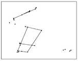
부가적으로, 라인들의 그룹들은 사이클들을 검출하기 위해 함께 결합될 수도 있다. 사이클 검출은 그래프 및 각각의 결과적인 서브그래프를, 각각의 결과적인 서브그래프가 하나의 사이클을 포함할 때까지 2 로 반복적으로 분할하는 것을 포함한다. 하나의 사이클을 포함하는 결과적인 서브그래프들은 관심있는 서브그래프들로서 리포팅된다. 사이클 검출이 도 11 에 도시되어 있으며, 도 11 은, 2 로 분할되고 이에 의해 1개 사이클 및 3개 사이클들을 포함하는 서브그래프들을 생성하는 4개의 사이클들을 포함하는 그래프를 도시한다. 3개 사이클들을 갖는 서브그래프는 다시 분할되어, 부가적인 서브그래프들을 생성하며, 이 부가적인 서브그래프들은 각각의 서브그래프가 오직 1개의 사이클만을 가질 때까지 추가로 분할된다. 그 후, 1개 사이클을 포함하는 서브그래프들 모두가 결과로서 반환된다. 이러한 프로세스의 2개의 메인 컴포넌트들은 하기에서 예시되는 사이클 검출 및 그래프 분할이다. 예로써, 도 12a 및 도 12b 는, 각각, 점선 및 도트-대시 라인으로 식별되는, 에지들을 나타낸 오리지널 그래프 및 추출된 사이클들을 나타낸 그래프를 도시한 것이다.In addition, groups of lines may be combined together to detect cycles. Cycle detection involves iteratively dividing the graph and each resulting subgraph into two until each resulting subgraph contains one cycle. The resulting subgraphs containing one cycle are reported as the subgraphs of interest. Cycle detection is shown in FIG. 11, which shows a graph comprising four cycles divided into two and thereby creating subgraphs containing one cycle and three cycles. The subgraph with three cycles is subdivided again to create additional subgraphs, which are further divided until each subgraph has only one cycle. Then, all of the subgraphs containing one cycle are returned as a result. The two main components of this process are cycle detection and graph segmentation, which are illustrated below. As an example, FIGS. 12A and 12B show an original graph showing edges and a graph showing extracted cycles, respectively, identified by dashed lines and dot-dash lines.
사이클 검출은 다양한 방식들로 수행될 수도 있다. 논의를 용이하게 하기 위해, H0 가 정점들의 공간을 나타낸다고 한다. 예를 들어, 도 10 에 도시된 서브그래프를 참조하면, H0 는,Cycle detection may be performed in various ways. To facilitate the discussion, it is assumed that H0 represents the space of the vertices. For example, referring to the subgraph shown in FIG. 10, H0 is

이도록 정점들의 세트 {A,B,C,D} 의 거듭제곱 세트이다.Is the power set of the set of vertices {A, B, C, D}.
추가로, H1 은, 도 10 과 유사하지만,In addition, H1 is similar to FIG. 10,

이도록 에지들 (e1-e4) 을 라벨링한 도 13 에 도시된 바와 같이 에지들의 세트 {e1,e2,e3,e4} 의 거듭제곱 세트를 나타낸다.Denotes a power set of the set of edges {e1 , e2 , e3 , e4 } as shown in FIG. 13, which labels the edges e1 -e4 to be.
사이클 검출은 또한, 다음과 같이 정의된 경계 연산자 ∂를 이용하여 수행될 수도 있다:Cycle detection may also be performed using the boundary operator ∂ defined as follows:

따라서, 경계 연산자 하에서, 사이클c ∈ H1 은 다음과 같이 정의될 수 있다:Thus, under the boundary operator, the cyclec ∈ H1 can be defined as follows:

사이클들 C 의 공간은 벡터 공간이고 ∂의 널 공간이며 사이클들의 수는 제로와 동일한 ∂의 고유값 (eigenvalue) 의 수와 동일함을 유의해야 한다.Note that the space of cycles C is a vector space and the null space of ∂ and the number of cycles is equal to the number of eigenvalues of ∂ equal to zero.
예로써, 도 13 에 도시된 그래프에 대해, 경계 연산자 ∂는 ∂(e)=De로서 수학적으로 표현될 수 있으며, 여기서, 매트릭스 D 는For example, for the graph shown in FIG. 13, the boundary operator ∂ can be mathematically represented as ∂ (e ) =De , where matrix D is

에 의해 주어진다.Lt; / RTI >
예를 들어, E.g,

이다.to be.
이러한 디스크립션에 기초하여, 에지들 (e1, e2, e3, 및 e4) 은 모듈러 2 가산에 따르기 때문에 사이클을 형성한다:Based on this description, the edges e1 , e2 , e3 , and e4 form a cycle because they follow the modular 2 addition:

예로써, 도 14 는 4개의 정점들 사이의 5개의 라인들을 도시한다. 사이클들의 수는, 제로와 동일한 라플라시안 매트릭스의 고유값들의 수를 고찰함으로써 발견될 수 있다. 이 예에 있어서, 라플라시안 매트릭스 L=DTD 이By way of example, FIG. 14 shows five lines between four vertices. The number of cycles can be found by considering the number of eigenvalues of the Laplacian matrix equal to zero. In this example, the Laplacian matrix L = DT D is

에 의해 주어진다.Lt; / RTI >
수학식 11 에 나타낸 바와 같이, 도 14 에 도시된 사이클들의 그래프에 대해 2개의 제로 고유값들이 존재하고, 따라서, 2개의 사이클들이 존재한다. 따라서, 도 14 에 도시된 그래프는, 분할이 경계 포인트들에서 발생하는 도 15 에 도시된 바와 같이 분할되어야 한다. 그래프 분할을 위한 적절한 구현은 Harish Chintakunta, Hamid Krim, Divide 및 Conquer 에 의해 "Localizing Coverage holes in Sensor Networks", IEEE SECON, 2010년 6월호에 기술되며, 이는 본 명세서에 참조로 통합된다. 그래프 분할이 수행된 이후, 각각의 서브그래프에 있어서의 폐쇄된 경로가 발견되고, 관심있는 영역의 경계인 것으로 고려된다. 그 후, 이들 결과적인 사이클들은 트래킹 프로세스에서 이용될 수도 있다.As shown in equation (11), there are two zero eigenvalues for the graph of the cycles shown in FIG. 14, and therefore there are two cycles. Thus, the graph shown in FIG. 14 should be split as shown in FIG. 15 where splitting occurs at boundary points. Suitable implementations for graph segmentation are described by Harish Chintakunta, Hamid Krim, Divide and Conquer in "Localizing Coverage holes in Sensor Networks," IEEE SECON, June 2010, which is incorporated herein by reference. After the graph segmentation is performed, a closed path in each subgraph is found and considered to be the boundary of the region of interest. These resulting cycles may then be used in the tracking process.
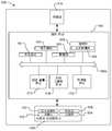
도 16 은 라인들의 그룹을 이용하여 오브젝트들을 트래킹하는 것이 가능한 모바일 플랫폼 (100) 의 블록 다이어그램이다. 모바일 플랫폼 (100) 은 카메라 (110) 뿐 아니라 사용자 인터페이스 (150) 를 포함하고, 이 사용자 인터페이스는 카메라 (110) 에 의해 캡처된 이미지들을 디스플레이하는 것이 가능한 디스플레이 (102) 를 포함한다. 사용자 인터페이스 (150) 는 또한, 사용자가 모바일 플랫폼 (100) 에 정보를 입력할 수 있는 키패드 (152) 또는 다른 입력 디바이스를 포함할 수도 있다. 요구된다면, 키패드 (152) 는 터치 센서를 갖는 디스플레이 (102) 로 가상 키패드를 통합함으로써 제거될 수도 있다. 사용자 인터페이스 (150) 는 또한, 예를 들어, 모바일 플랫폼이 셀룰러 전화이면 마이크로폰 (106) 및 스피커 (104) 를 포함할 수도 있다. 마이크로폰 (106) 은 오디오 주석을 입력하는데 사용될 수도 있다. 물론, 모바일 플랫폼 (100) 은 본 개시에 관련없는 다른 엘리먼트들을 포함할 수도 있다.16 is a block diagram of a
모바일 플랫폼 (100) 은 또한, 카메라 (110) 및 사용자 인터페이스 (150) 뿐 아니라 제공될 수도 있는 다른 시스템들에 접속되고 통신하는 제어 유닛 (160) 을 포함한다. 예를 들어, 가속도계들, 자이로스코프들, 자력계들과 같은 모션 및/또는 포지션 센서들이 제공되고 트래킹에 이용되는 부가 정보를 제공하기 위해 사용될 수도 있다. 제어 유닛 (160) 은 상기 논의된 바와 같은 카메라 (110) 로부터의 데이터를 수용 및 프로세싱한다. 제어 유닛 (160) 은 버스 (160b), 프로세서 (161) 및 관련 메모리 (164), 하드웨어 (162), 소프트웨어 (165), 및 펌웨어 (163) 에 의해 제공될 수도 있다. 모바일 플랫폼 (100) 은, 도 1 에 도시된 비전 기반 트래킹 유닛 (112) 을 구성하고 상기 설명된 바와 같이 동작하는 라인 검출 유닛 (172), 라인 그룹핑 유닛 (174), 및 트래킹 유닛 (176) 을 포함한다. 라인 검출 유닛 (172), 라인 그룹핑 유닛 (174), 및 트래킹 유닛 (176) 은 명료화를 위해 별도로 도시되고 프로세서 (161) 로부터 분리되지만, 프로세서 (161) 에서 구동되는 소프트웨어 (165) 에서의 명령들에 기초하여 프로세서 (161) 에 구현되고/되거나 단일 유닛일 수도 있다. 본 명세서에서 사용된 바와 같이, 프로세서 (161) 뿐 아니라 라인 검출 유닛 (172), 라인 그룹핑 유닛 (174) 및 트래킹 유닛 (176) 중 하나 이상은 하나 이상의 마이크로프로세서들, 임베디드 프로세서들, 제어기들, 주문형 집적회로들 (ASICs), 디지털 신호 프로세서들 (DSPs) 등을 포함할 수 있지만 반드시 포함할 필요는 없음이 이해될 것이다. 용어 '프로세서' 는 특정 하드웨어보다는 시스템에 의해 구현된 기능들을 기술하도록 의도된다. 더욱이, 본 명세서에서 사용된 바와 같이, 용어 "메모리" 는 모바일 플랫폼과 연관된 롱텀, 숏텀, 또는 다른 메모리를 포함한 임의의 타입의 컴퓨터 저장 매체를 지칭하고, 메모리의 임의의 특정 타입 또는 메모리들의 수, 또는 메모리가 저장되는 매체의 타입에 한정되지 않는다.
본 명세서에서 설명된 방법들은 어플리케이션에 의존하여 다양한 수단들에 의해 구현될 수도 있다. 예를 들어, 이들 방법들은 하드웨어 (162), 펌웨어 (163), 소프트웨어 (165), 또는 이들의 임의의 조합에서 구현될 수도 있다. 하드웨어 구현에 대해, 프로세싱 유닛들은 하나 이상의 주문형 집적회로들 (ASICs), 디지털 신호 프로세서들 (DSPs), 디지털 신호 프로세싱 디바이스들 (DSPDs), 프로그래머블 로직 디바이스들 (PLDs), 필드 프로그래머블 게이트 어레이들 (FPGAs), 프로세서들, 제어기들, 마이크로-제어기들, 마이크로프로세서들, 전자 디바이스들, 본 명세서에서 설명된 기능들을 수행하도록 설계된 다른 전자 유닛들, 또는 이들의 조합 내에서 구현될 수도 있다.The methods described herein may be implemented by various means depending on the application. For example, these methods may be implemented in
펌웨어 및/또는 소프트웨어 구현에 대해, 방법들이, 본 명세서에서 설명된 기능들을 수행하는 모듈들 (예를 들어, 절차들, 기능부들 등) 로 구현될 수도 있다. 명령들을 유형으로 수록하는 임의의 머신 판독가능 매체가 본 명세서에서 설명된 방법들을 구현하는데 사용될 수도 있다. 예를 들어, 소프트웨어 코드들은 메모리 (164) 에 저장되고 프로세서 (161) 에 의해 실행될 수도 있다. 메모리는 프로세서 (161) 내에 또는 프로세서 외부에 구현될 수도 있다.For firmware and / or software implementations, the methods may be implemented with modules (eg, procedures, functionalities, etc.) that perform the functions described herein. Any machine readable medium containing the types of instructions may be used to implement the methods described herein. For example, software codes may be stored in
펌웨어 및/또는 소프트웨어에서 구현된다면, 그 기능들은 컴퓨터 판독가능 매체 상에 하나 이상의 명령들 또는 코드로서 저장될 수도 있다. 예들로는, 데이터 구조로 인코딩된 비-일시적인 컴퓨터 판독가능 매체 및 컴퓨터 프로그램으로 인코딩된 컴퓨터 판독가능 매체를 포함한다. 컴퓨터 판독가능 매체는 물리적 컴퓨터 저장 매체를 포함한다. 저장 매체는, 컴퓨터에 의해 액세스될 수 있는 임의의 가용 매체일 수도 있다. 한정이 아닌 예로서, 그러한 컴퓨터 판독가능 매체는 RAM, ROM, 플래시 메모리, EEPROM, CD-ROM 또는 다른 광학 디스크 저장부, 자기 디스크 저장부 또는 다른 자기 저장 디바이스들, 또는 원하는 프로그램 코드를 명령들 또는 데이터 구조들의 형태로 저장하는데 이용될 수 있고 또한 컴퓨터에 의해 액세스될 수 있는 임의의 다른 매체를 포함할 수 있으며; 본 명세서에서 사용된 바와 같이, 디스크 (disk) 및 디스크 (disc) 는 컴팩트 디스크 (CD), 레이저 디스크, 광학 디스크, 디지털 다기능 디스크 (DVD), 플로피 디스크 및 블루레이 디스크를 포함하고, 여기서, 디스크(disk)들은 통상적으로 데이터를 자기적으로 재생하지만 디스크(disc)들은 레이저들을 이용하여 데이터를 광학적으로 재생한다. 상기의 조합들이 또한, 컴퓨터 판독가능 매체의 범위 내에 포함되어야 한다.If implemented in firmware and / or software, the functions may be stored as one or more instructions or code on a computer readable medium. Examples include non-transitory computer readable media encoded with a data structure and computer readable media encoded with a computer program. Computer readable media include physical computer storage media. The storage medium may be any available media that can be accessed by a computer. By way of example, and not limitation, such computer readable media may comprise RAM, ROM, flash memory, EEPROM, CD-ROM or other optical disk storage, magnetic disk storage or other magnetic storage devices, or instructions or code of desired program code. May include any other medium that can be used to store data in the form of data structures and that can be accessed by a computer; As used herein, disks and disks include compact disks (CDs), laser disks, optical disks, digital versatile disks (DVDs), floppy disks and Blu-ray disks, where disks Disks typically reproduce data magnetically while disks optically reproduce data using lasers. Combinations of the above should also be included within the scope of computer readable media.
본 발명이 교육적 목적으로 특정 실시형태들과 관련하여 예시되지만, 본 발명은 이에 한정되지 않는다. 다양한 적응들 및 변형들이 본 발명의 범위로부터 일탈함없이 행해질 수도 있다. 따라서, 첨부된 청구항들의 사상 및 범위는 전술한 설명에 한정되지 않아야 한다.Although the present invention is illustrated in connection with specific embodiments for educational purposes, the invention is not so limited. Various adaptations and modifications may be made without departing from the scope of the present invention. Accordingly, the spirit and scope of the appended claims should not be limited to the foregoing description.
Claims (28)
Translated fromKorean상기 오브젝트의 상기 이미지에 있어서 복수의 라인들을 검출하는 단계;
상기 복수의 라인들로부터 라인들의 그룹을 형성하는 단계; 및
상기 라인들의 그룹을 이용하여 상기 오브젝트를 트래킹하는 단계를 포함하는, 방법.Capturing an image of the object to be tracked;
Detecting a plurality of lines in the image of the object;
Forming a group of lines from the plurality of lines; And
Tracking the object using the group of lines.
상기 라인들의 그룹은 연결된 라인들을 포함하는, 방법.The method according to claim 1,
The group of lines comprises connected lines.
상기 연결된 라인들은 폐쇄된 도형을 형성하는, 방법.3. The method of claim 2,
The connected lines form a closed figure.
상기 복수의 라인들로부터 라인들의 그룹을 형성하는 단계는,
상기 복수의 라인들의 모든 교차 포인트들을 산출하는 단계;
상기 교차 포인트들을 이용하여 연결된 라인들을 식별하는 단계; 및
상기 연결된 라인들로 상기 라인들의 그룹을 형성하는 단계를 포함하는, 방법.The method according to claim 1,
Forming a group of lines from the plurality of lines,
Calculating all intersection points of the plurality of lines;
Identifying connected lines using the intersection points; And
Forming the group of lines with the connected lines.
상기 복수의 라인들로부터 라인들의 그룹을 형성하는 단계는,
상기 복수의 라인들로부터 그래프를 구성하는 단계;
상기 복수의 라인들의 모든 교차 포인트들을 산출하는 단계;
교차 포인트들의 각 쌍 사이의 연결들을 이용하여 관심있는 서브그래프를 생성하는 단계; 및
상기 관심있는 서브그래프로부터 상기 라인들의 그룹을 형성하는 단계를 포함하는, 방법.The method according to claim 1,
Forming a group of lines from the plurality of lines,
Constructing a graph from the plurality of lines;
Calculating all intersection points of the plurality of lines;
Generating a subgraph of interest using the connections between each pair of intersection points; And
Forming the group of lines from the subgraph of interest.
상기 오브젝트의 레퍼런스 모델을 상기 관심있는 서브그래프에 매칭함으로써 트래킹될 오브젝트를 검출하는 단계를 더 포함하는, 방법.6. The method of claim 5,
Detecting the object to be tracked by matching the reference model of the object to the subgraph of interest.
상기 라인들의 그룹을 이용하여 상기 오브젝트를 트래킹하는 단계는 상기 오브젝트의 레퍼런스 모델을 상기 관심있는 서브그래프에 매칭하는 단계를 포함하는, 방법.6. The method of claim 5,
Tracking the object using the group of lines includes matching a reference model of the object to the subgraph of interest.
상기 관심있는 서브그래프를 생성하는 단계는,
상기 그래프 및 각각의 결과적인 서브그래프를, 상기 각각의 결과적인 서브그래프가 하나의 사이클을 포함할 때까지 2 로 반복적으로 분할하는 단계; 및
하나의 사이클을 포함하는 결과적인 서브그래프들을 관심있는 서브그래프들로서 리포팅하는 단계를 포함하는, 방법.6. The method of claim 5,
Generating the subgraph of interest,
Iteratively dividing the graph and each resulting subgraph into two until each resulting subgraph contains one cycle; And
Reporting the resulting subgraphs containing one cycle as subgraphs of interest.
상기 라인들의 그룹을 이용하여 상기 오브젝트를 트래킹하는 단계는 상기 라인들의 그룹을 이용하여 상기 오브젝트의 현재 이미지를 상기 오브젝트의 이전 이미지와 비교하는 단계를 포함하는, 방법.The method according to claim 1,
Tracking the object using the group of lines comprises comparing a current image of the object with a previous image of the object using the group of lines.
상기 카메라에 접속된 프로세서를 포함하고,
상기 프로세서는 트래킹될 오브젝트의 상기 카메라에 의해 캡처된 이미지에 있어서 복수의 라인들을 검출하고, 상기 복수의 라인들로부터 라인들의 그룹을 형성하며, 그리고 상기 라인들의 그룹을 이용하여 상기 오브젝트를 트래킹하도록 구성되는, 장치.camera; And
A processor connected to the camera,
The processor is configured to detect a plurality of lines in the image captured by the camera of the object to be tracked, form a group of lines from the plurality of lines, and track the object using the group of lines. Device.
상기 라인들의 그룹은 연결된 라인들을 포함하는, 장치.11. The method of claim 10,
Wherein the group of lines comprises connected lines.
상기 연결된 라인들은 폐쇄된 도형을 형성하는, 장치.The method of claim 11,
The connected lines form a closed figure.
상기 프로세서는, 상기 복수의 라인들의 모든 교차 포인트들을 산출하고, 상기 교차 포인트들을 이용하여 연결된 라인들을 식별하며, 그리고 상기 연결된 라인들로 상기 라인들의 그룹을 형성하도록 구성됨으로써 상기 복수의 라인들로부터 상기 라인들의 그룹을 형성하도록 구성되는, 장치.11. The method of claim 10,
The processor is configured to calculate all intersection points of the plurality of lines, identify connected lines using the intersection points, and form the group of lines with the connected lines so that the plurality of lines are separated from the plurality of lines. And to form a group of lines.
상기 프로세서는, 상기 복수의 라인들로부터 그래프를 구성하고; 상기 복수의 라인들의 모든 교차 포인트들을 산출하고; 교차 포인트들의 각 쌍 사이의 연결들을 이용하여 관심있는 서브그래프를 생성하며; 그리고 상기 관심있는 서브그래프로부터 상기 라인들의 그룹을 형성하도록 구성됨으로써 상기 복수의 라인들로부터 상기 라인들의 그룹을 형성하도록 구성되는, 장치.11. The method of claim 10,
The processor constructs a graph from the plurality of lines; Calculate all intersection points of the plurality of lines; Generate connections of interest using the connections between each pair of intersection points; And form the group of lines from the subgraph of interest, thereby forming the group of lines from the plurality of lines.
상기 프로세서는, 상기 오브젝트의 레퍼런스 모델을 상기 관심있는 서브그래프에 매칭하도록 구성됨으로써 트래킹될 오브젝트를 검출하도록 추가로 구성되는, 장치.15. The method of claim 14,
And the processor is further configured to detect the object to be tracked by being configured to match the reference model of the object to the subgraph of interest.
상기 프로세서는, 상기 오브젝트의 레퍼런스 모델을 상기 관심있는 서브그래프에 매칭하도록 구성됨으로써 상기 라인들의 그룹을 이용하여 상기 오브젝트를 트래킹하도록 구성되는, 장치.15. The method of claim 14,
And the processor is configured to track the object using the group of lines by being configured to match a reference model of the object to the subgraph of interest.
상기 프로세서는, 상기 그래프 및 각각의 결과적인 서브그래프를, 상기 각각의 결과적인 서브그래프가 하나의 사이클을 포함할 때까지 2 로 반복적으로 분할하며; 그리고 하나의 사이클을 포함하는 결과적인 서브그래프들을 관심있는 서브그래프들로서 리포팅하도록 구성됨으로써 상기 관심있는 서브그래프를 생성하도록 구성되는, 장치.15. The method of claim 14,
The processor recursively divides the graph and each resulting subgraph into two until each resulting subgraph contains one cycle; And generate the subgraph of interest by being configured to report the resulting subgraphs containing one cycle as the subgraphs of interest.
상기 프로세서는, 상기 카메라에 의해 캡처된 상기 오브젝트의 현재 이미지를 상기 카메라에 의해 캡처된 상기 오브젝트의 이전 이미지와 비교하도록 구성됨으로써 상기 라인들의 그룹을 이용하여 상기 오브젝트를 트래킹하도록 구성되는, 장치.11. The method of claim 10,
The processor is configured to track the object using the group of lines by being configured to compare a current image of the object captured by the camera with a previous image of the object captured by the camera.
상기 오브젝트의 상기 이미지에 있어서 복수의 라인들을 검출하는 수단;
상기 복수의 라인들로부터 라인들의 그룹을 형성하는 수단; 및
상기 라인들의 그룹을 이용하여 상기 오브젝트를 트래킹하는 수단을 포함하는, 장치.Means for capturing an image of an object to be tracked;
Means for detecting a plurality of lines in the image of the object;
Means for forming a group of lines from the plurality of lines; And
Means for tracking the object using the group of lines.
상기 라인들의 그룹은, 폐쇄된 도형을 형성하는 연결된 라인들을 포함하는, 장치.20. The method of claim 19,
Wherein said group of lines comprises connected lines forming a closed figure.
상기 복수의 라인들로부터 라인들의 그룹을 형성하는 수단은,
상기 복수의 라인들의 모든 교차 포인트들을 산출하는 수단;
상기 교차 포인트들을 이용하여 연결된 라인들을 식별하는 수단; 및
상기 연결된 라인들로 상기 라인들의 그룹을 형성하는 수단을 포함하는, 장치.20. The method of claim 19,
Means for forming a group of lines from the plurality of lines,
Means for calculating all intersection points of the plurality of lines;
Means for identifying connected lines using the intersection points; And
Means for forming the group of lines into the connected lines.
상기 복수의 라인들로부터 라인들의 그룹을 형성하는 수단은,
상기 복수의 라인들로부터 그래프를 구성하는 수단;
상기 복수의 라인들의 모든 교차 포인트들을 산출하는 수단;
교차 포인트들의 각 쌍 사이의 연결들을 이용하여 관심있는 서브그래프를 생성하는 수단; 및
상기 관심있는 서브그래프로부터 상기 라인들의 그룹을 형성하는 수단을 포함하는, 장치.20. The method of claim 19,
Means for forming a group of lines from the plurality of lines,
Means for constructing a graph from the plurality of lines;
Means for calculating all intersection points of the plurality of lines;
Means for generating a subgraph of interest using the connections between each pair of intersection points; And
Means for forming the group of lines from the subgraph of interest.
상기 라인들의 그룹을 이용하여 상기 오브젝트를 트래킹하는 수단은 상기 라인들의 그룹을 이용하여 상기 오브젝트의 현재 이미지를 상기 오브젝트의 이전 이미지와 비교하는 수단을 포함하는, 장치.20. The method of claim 19,
Means for tracking the object using the group of lines includes means for comparing the current image of the object with a previous image of the object using the group of lines.
트래킹될 오브젝트의 이미지를 캡처하기 위한 프로그램 코드;
상기 오브젝트의 상기 이미지에 있어서 복수의 라인들을 검출하기 위한 프로그램 코드;
상기 복수의 라인들로부터 라인들의 그룹을 형성하기 위한 프로그램 코드; 및
상기 라인들의 그룹을 이용하여 상기 오브젝트를 트래킹하기 위한 프로그램 코드를 포함하는, 비-일시적인 컴퓨터 판독가능 매체.A non-transitory computer readable medium containing stored program code, comprising:
Program code for capturing an image of an object to be tracked;
Program code for detecting a plurality of lines in the image of the object;
Program code for forming a group of lines from the plurality of lines; And
And non-transitory program code for tracking the object using the group of lines.
상기 라인들의 그룹은, 폐쇄된 도형을 형성하는 연결된 라인들을 포함하는, 비-일시적인 컴퓨터 판독가능 매체.25. The method of claim 24,
And the group of lines comprises connected lines forming a closed figure.
상기 복수의 라인들로부터 라인들의 그룹을 형성하기 위한 프로그램 코드는,
상기 복수의 라인들의 모든 교차 포인트들을 산출하기 위한 프로그램 코드;
상기 교차 포인트들을 이용하여 연결된 라인들을 식별하기 위한 프로그램 코드; 및
상기 연결된 라인들로 상기 라인들의 그룹을 형성하기 위한 프로그램 코드를 포함하는, 비-일시적인 컴퓨터 판독가능 매체.25. The method of claim 24,
Program code for forming a group of lines from the plurality of lines,
Program code for calculating all intersection points of the plurality of lines;
Program code for identifying connected lines using the intersection points; And
Non-transitory computer readable medium comprising program code for forming the group of lines into the connected lines.
상기 복수의 라인들로부터 라인들의 그룹을 형성하는 것은,
상기 복수의 라인들로부터 그래프를 구성하기 위한 프로그램 코드;
상기 복수의 라인들의 모든 교차 포인트들을 산출하기 위한 프로그램 코드;
교차 포인트들의 각 쌍 사이의 연결들을 이용하여 관심있는 서브그래프를 생성하기 위한 프로그램 코드; 및
상기 관심있는 서브그래프로부터 상기 라인들의 그룹을 형성하기 위한 프로그램 코드를 포함하는, 비-일시적인 컴퓨터 판독가능 매체.25. The method of claim 24,
Forming a group of lines from the plurality of lines,
Program code for constructing a graph from the plurality of lines;
Program code for calculating all intersection points of the plurality of lines;
Program code for generating a subgraph of interest using the connections between each pair of intersection points; And
Non-transitory computer readable medium comprising program code for forming the group of lines from the subgraph of interest.
상기 라인들의 그룹을 이용하여 상기 오브젝트를 트래킹하기 위한 프로그램 코드는 상기 라인들의 그룹을 이용하여 상기 오브젝트의 현재 이미지를 상기 오브젝트의 이전 이미지와 비교하기 위한 프로그램 코드를 포함하는, 비-일시적인 컴퓨터 판독가능 매체.25. The method of claim 24,
Program code for tracking the object using the group of lines includes program code for comparing the current image of the object with a previous image of the object using the group of lines. media.
Applications Claiming Priority (5)
| Application Number | Priority Date | Filing Date | Title |
|---|---|---|---|
| US201161530907P | 2011-09-02 | 2011-09-02 | |
| US61/530,907 | 2011-09-02 | ||
| US13/416,721 | 2012-03-09 | ||
| US13/416,721US9582896B2 (en) | 2011-09-02 | 2012-03-09 | Line tracking with automatic model initialization by graph matching and cycle detection |
| PCT/US2012/051737WO2013032785A1 (en) | 2011-09-02 | 2012-08-21 | Line tracking with automatic model initialization by graph matching and cycle detection |
Related Child Applications (1)
| Application Number | Title | Priority Date | Filing Date |
|---|---|---|---|
| KR1020167006998ADivisionKR20160036081A (en) | 2011-09-02 | 2012-08-21 | Line tracking with automatic model initialization by graph matching and cycle detection |
Publications (1)
| Publication Number | Publication Date |
|---|---|
| KR20140043159Atrue KR20140043159A (en) | 2014-04-08 |
Family
ID=47752857
Family Applications (2)
| Application Number | Title | Priority Date | Filing Date |
|---|---|---|---|
| KR1020147005465ACeasedKR20140043159A (en) | 2011-09-02 | 2012-08-21 | Line tracking with automatic model initialization by graph matching and cycle detection |
| KR1020167006998AWithdrawnKR20160036081A (en) | 2011-09-02 | 2012-08-21 | Line tracking with automatic model initialization by graph matching and cycle detection |
Family Applications After (1)
| Application Number | Title | Priority Date | Filing Date |
|---|---|---|---|
| KR1020167006998AWithdrawnKR20160036081A (en) | 2011-09-02 | 2012-08-21 | Line tracking with automatic model initialization by graph matching and cycle detection |
Country Status (6)
| Country | Link |
|---|---|
| US (1) | US9582896B2 (en) |
| EP (1) | EP2751781A1 (en) |
| JP (2) | JP2014529823A (en) |
| KR (2) | KR20140043159A (en) |
| CN (1) | CN103765477B (en) |
| WO (1) | WO2013032785A1 (en) |
Families Citing this family (5)
| Publication number | Priority date | Publication date | Assignee | Title |
|---|---|---|---|---|
| EP2829054A1 (en)* | 2012-03-19 | 2015-01-28 | Sony Mobile Communications AB | Smart cameras |
| US9626579B2 (en)* | 2014-05-05 | 2017-04-18 | Qualcomm Incorporated | Increasing canny filter implementation speed |
| US9665804B2 (en)* | 2014-11-12 | 2017-05-30 | Qualcomm Incorporated | Systems and methods for tracking an object |
| US10115031B1 (en)* | 2015-02-27 | 2018-10-30 | Evernote Corporation | Detecting rectangular page and content boundaries from smartphone video stream |
| US11044390B2 (en)* | 2016-02-10 | 2021-06-22 | Karl Storz Imaging, Inc. | Imaging system for identifying a boundary between active and inactive portions of a digital image |
Family Cites Families (13)
| Publication number | Priority date | Publication date | Assignee | Title |
|---|---|---|---|---|
| US4891762A (en)* | 1988-02-09 | 1990-01-02 | Chotiros Nicholas P | Method and apparatus for tracking, mapping and recognition of spatial patterns |
| US6173066B1 (en) | 1996-05-21 | 2001-01-09 | Cybernet Systems Corporation | Pose determination and tracking by matching 3D objects to a 2D sensor |
| JP3800905B2 (en) | 1999-07-27 | 2006-07-26 | 松下電工株式会社 | Image feature tracking processing method, image feature tracking processing device, and three-dimensional data creation method |
| US6489922B1 (en)* | 2000-04-22 | 2002-12-03 | American Gnc Corporation | Passive/ranging/tracking processing method for collision avoidance guidance and control |
| US7450743B2 (en) | 2004-01-21 | 2008-11-11 | Siemens Medical Solutions Usa, Inc. | Method and system of affine registration of inter-operative two dimensional images and pre-operative three dimensional images |
| US7738705B2 (en)* | 2004-06-30 | 2010-06-15 | Stefano Casadei | Hierarchical method and system for pattern recognition and edge detection |
| US7801330B2 (en)* | 2005-06-24 | 2010-09-21 | Objectvideo, Inc. | Target detection and tracking from video streams |
| US7831098B2 (en)* | 2006-11-07 | 2010-11-09 | Recognition Robotics | System and method for visual searching of objects using lines |
| CN101493889B (en)* | 2008-01-23 | 2011-12-07 | 华为技术有限公司 | Method and apparatus for tracking video object |
| JP5388932B2 (en) | 2009-04-30 | 2014-01-15 | キヤノン株式会社 | Information processing apparatus and control method thereof |
| JP5321417B2 (en) | 2009-11-10 | 2013-10-23 | 株式会社Jvcケンウッド | Perspective transformation parameter generation device, image correction device, perspective transformation parameter generation method, image correction method, and program |
| US8358808B2 (en)* | 2010-01-08 | 2013-01-22 | University Of Washington | Video-based vehicle detection and tracking using spatio-temporal maps |
| WO2013052613A1 (en)* | 2011-10-04 | 2013-04-11 | Institute For Hepatitis And Virus Research | Substituted aminothiazoles as inhibitors of cancers, including hepatocellular carcinoma, and as inhibitors of hepatitis virus replication |
- 2012
- 2012-03-09USUS13/416,721patent/US9582896B2/enactiveActive
- 2012-08-21WOPCT/US2012/051737patent/WO2013032785A1/enactiveApplication Filing
- 2012-08-21CNCN201280041546.0Apatent/CN103765477B/ennot_activeExpired - Fee Related
- 2012-08-21EPEP12754166.2Apatent/EP2751781A1/ennot_activeWithdrawn
- 2012-08-21KRKR1020147005465Apatent/KR20140043159A/ennot_activeCeased
- 2012-08-21JPJP2014528450Apatent/JP2014529823A/enactivePending
- 2012-08-21KRKR1020167006998Apatent/KR20160036081A/ennot_activeWithdrawn
- 2016
- 2016-04-28JPJP2016090685Apatent/JP6240706B2/enactiveActive
Also Published As
| Publication number | Publication date |
|---|---|
| JP6240706B2 (en) | 2017-11-29 |
| US9582896B2 (en) | 2017-02-28 |
| US20130057700A1 (en) | 2013-03-07 |
| CN103765477B (en) | 2016-08-17 |
| CN103765477A (en) | 2014-04-30 |
| JP2016136439A (en) | 2016-07-28 |
| KR20160036081A (en) | 2016-04-01 |
| EP2751781A1 (en) | 2014-07-09 |
| WO2013032785A1 (en) | 2013-03-07 |
| JP2014529823A (en) | 2014-11-13 |
Similar Documents
| Publication | Publication Date | Title |
|---|---|---|
| JP5950973B2 (en) | Method, apparatus and system for selecting a frame | |
| US10573018B2 (en) | Three dimensional scene reconstruction based on contextual analysis | |
| JP6043856B2 (en) | Head pose estimation using RGBD camera | |
| CN107111880B (en) | Occlusion Handling for Computer Vision | |
| US10373380B2 (en) | 3-dimensional scene analysis for augmented reality operations | |
| JP6348574B2 (en) | Monocular visual SLAM using global camera movement and panoramic camera movement | |
| JP5847924B2 (en) | 2D image capture for augmented reality representation | |
| EP3206163B1 (en) | Image processing method, mobile device and method for generating a video image database | |
| US8879894B2 (en) | Pixel analysis and frame alignment for background frames | |
| JP2019075082A (en) | Video processing method and device using depth value estimation | |
| US20120206597A1 (en) | Moving object detection apparatus and moving object detection method | |
| CN113705669A (en) | Data matching method and device, electronic equipment and storage medium | |
| KR20140014298A (en) | Planar mapping and tracking for mobile devices | |
| CN108027884A (en) | Optimization object detects | |
| JP6240706B2 (en) | Line tracking using automatic model initialization with graph matching and cycle detection | |
| CN112085842A (en) | Depth value determination method and device, electronic equipment and storage medium | |
| JP6163732B2 (en) | Image processing apparatus, program, and method | |
| KR102542363B1 (en) | Method for recognizing object in 3 dimentional space |
Legal Events
| Date | Code | Title | Description |
|---|---|---|---|
| A201 | Request for examination | ||
| PA0105 | International application | Patent event date:20140228 Patent event code:PA01051R01D Comment text:International Patent Application | |
| PA0201 | Request for examination | Patent event code:PA02012R01D Patent event date:20140228 Comment text:Request for Examination of Application | |
| PG1501 | Laying open of application | ||
| E902 | Notification of reason for refusal | ||
| PE0902 | Notice of grounds for rejection | Comment text:Notification of reason for refusal Patent event date:20150323 Patent event code:PE09021S01D | |
| E601 | Decision to refuse application | ||
| PE0601 | Decision on rejection of patent | Patent event date:20151216 Comment text:Decision to Refuse Application Patent event code:PE06012S01D Patent event date:20150323 Comment text:Notification of reason for refusal Patent event code:PE06011S01I | |
| A107 | Divisional application of patent | ||
| J201 | Request for trial against refusal decision | ||
| PA0104 | Divisional application for international application | Comment text:Divisional Application for International Patent Patent event code:PA01041R01D Patent event date:20160316 | |
| PJ0201 | Trial against decision of rejection | Patent event date:20160316 Comment text:Request for Trial against Decision on Refusal Patent event code:PJ02012R01D Patent event date:20151216 Comment text:Decision to Refuse Application Patent event code:PJ02011S01I Appeal kind category:Appeal against decision to decline refusal Appeal identifier:2016101001580 Request date:20160316 | |
| J301 | Trial decision | Free format text:TRIAL NUMBER: 2016101001580; TRIAL DECISION FOR APPEAL AGAINST DECISION TO DECLINE REFUSAL REQUESTED 20160316 Effective date:20180320 | |
| PJ1301 | Trial decision | Patent event code:PJ13011S01D Patent event date:20180320 Comment text:Trial Decision on Objection to Decision on Refusal Appeal kind category:Appeal against decision to decline refusal Request date:20160316 Decision date:20180320 Appeal identifier:2016101001580 |