KR20140042516A - Compressed energy storage apparatus using liquid refrigerant - Google Patents
Compressed energy storage apparatus using liquid refrigerantDownload PDFInfo
- Publication number
- KR20140042516A KR20140042516AKR1020120109370AKR20120109370AKR20140042516AKR 20140042516 AKR20140042516 AKR 20140042516AKR 1020120109370 AKR1020120109370 AKR 1020120109370AKR 20120109370 AKR20120109370 AKR 20120109370AKR 20140042516 AKR20140042516 AKR 20140042516A
- Authority
- KR
- South Korea
- Prior art keywords
- refrigerant
- compressed
- energy storage
- storage unit
- storage device
- Prior art date
- Legal status (The legal status is an assumption and is not a legal conclusion. Google has not performed a legal analysis and makes no representation as to the accuracy of the status listed.)
- Ceased
Links
- 239000003507refrigerantSubstances0.000titleclaimsabstractdescription127
- 238000004146energy storageMethods0.000titleclaimsabstractdescription64
- 239000007788liquidSubstances0.000title1
- 230000006835compressionEffects0.000claimsabstractdescription30
- 238000007906compressionMethods0.000claimsabstractdescription30
- 238000010438heat treatmentMethods0.000claimsabstractdescription4
- 238000000034methodMethods0.000claimsdescription20
- 239000012782phase change materialSubstances0.000claimsdescription6
- 238000010248power generationMethods0.000claimsdescription6
- 238000001704evaporationMethods0.000claims1
- 238000010586diagramMethods0.000description5
- 238000005338heat storageMethods0.000description5
- 239000000463materialSubstances0.000description4
- 238000010276constructionMethods0.000description3
- 239000011232storage materialSubstances0.000description3
- 238000012423maintenanceMethods0.000description2
- 230000008016vaporizationEffects0.000description2
- 238000002485combustion reactionMethods0.000description1
- 239000002826coolantSubstances0.000description1
- 230000004927fusionEffects0.000description1
- 230000001105regulatory effectEffects0.000description1
- 238000009834vaporizationMethods0.000description1
Images


Classifications
- F—MECHANICAL ENGINEERING; LIGHTING; HEATING; WEAPONS; BLASTING
- F02—COMBUSTION ENGINES; HOT-GAS OR COMBUSTION-PRODUCT ENGINE PLANTS
- F02C—GAS-TURBINE PLANTS; AIR INTAKES FOR JET-PROPULSION PLANTS; CONTROLLING FUEL SUPPLY IN AIR-BREATHING JET-PROPULSION PLANTS
- F02C6/00—Plural gas-turbine plants; Combinations of gas-turbine plants with other apparatus; Adaptations of gas-turbine plants for special use
- F02C6/14—Gas-turbine plants having means for storing energy, e.g. for meeting peak loads
- F02C6/16—Gas-turbine plants having means for storing energy, e.g. for meeting peak loads for storing compressed air
- F—MECHANICAL ENGINEERING; LIGHTING; HEATING; WEAPONS; BLASTING
- F01—MACHINES OR ENGINES IN GENERAL; ENGINE PLANTS IN GENERAL; STEAM ENGINES
- F01D—NON-POSITIVE DISPLACEMENT MACHINES OR ENGINES, e.g. STEAM TURBINES
- F01D15/00—Adaptations of machines or engines for special use; Combinations of engines with devices driven thereby
- F01D15/10—Adaptations for driving, or combinations with, electric generators
- F—MECHANICAL ENGINEERING; LIGHTING; HEATING; WEAPONS; BLASTING
- F01—MACHINES OR ENGINES IN GENERAL; ENGINE PLANTS IN GENERAL; STEAM ENGINES
- F01D—NON-POSITIVE DISPLACEMENT MACHINES OR ENGINES, e.g. STEAM TURBINES
- F01D19/00—Starting of machines or engines; Regulating, controlling, or safety means in connection therewith
- F01D19/02—Starting of machines or engines; Regulating, controlling, or safety means in connection therewith dependent on temperature of component parts, e.g. of turbine-casing
- F—MECHANICAL ENGINEERING; LIGHTING; HEATING; WEAPONS; BLASTING
- F01—MACHINES OR ENGINES IN GENERAL; ENGINE PLANTS IN GENERAL; STEAM ENGINES
- F01K—STEAM ENGINE PLANTS; STEAM ACCUMULATORS; ENGINE PLANTS NOT OTHERWISE PROVIDED FOR; ENGINES USING SPECIAL WORKING FLUIDS OR CYCLES
- F01K27/00—Plants for converting heat or fluid energy into mechanical energy, not otherwise provided for
- Y—GENERAL TAGGING OF NEW TECHNOLOGICAL DEVELOPMENTS; GENERAL TAGGING OF CROSS-SECTIONAL TECHNOLOGIES SPANNING OVER SEVERAL SECTIONS OF THE IPC; TECHNICAL SUBJECTS COVERED BY FORMER USPC CROSS-REFERENCE ART COLLECTIONS [XRACs] AND DIGESTS
- Y02—TECHNOLOGIES OR APPLICATIONS FOR MITIGATION OR ADAPTATION AGAINST CLIMATE CHANGE
- Y02E—REDUCTION OF GREENHOUSE GAS [GHG] EMISSIONS, RELATED TO ENERGY GENERATION, TRANSMISSION OR DISTRIBUTION
- Y02E60/00—Enabling technologies; Technologies with a potential or indirect contribution to GHG emissions mitigation
- Y02E60/16—Mechanical energy storage, e.g. flywheels or pressurised fluids
Landscapes
- Engineering & Computer Science (AREA)
- Mechanical Engineering (AREA)
- General Engineering & Computer Science (AREA)
- Chemical & Material Sciences (AREA)
- Combustion & Propulsion (AREA)
- Separation By Low-Temperature Treatments (AREA)
Abstract
Translated fromKoreanDescription
Translated fromKorean본 발명의 일 실시예는 액화냉매를 이용한 압축에너지 저장 장치에 관한 것이다.
One embodiment of the present invention relates to a compressed energy storage device using a liquefied refrigerant.
종래의 에너지 저장 방법은 크게 배터리를 이용하는 방법과 플라이휠을 이용하는 방법 그리고 압축공기를 이용하는 방법이 대표적이다.Conventional energy storage methods are typically a method using a battery, a flywheel method and a compressed air method.
이 중 대용량 에너지를 저장할 수 있는 것은 압축공기 저장 방식이다.Among them, a large amount of energy can be stored in the compressed air storage method.
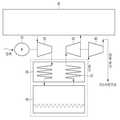
도 1은 종래의 대표적인 압축공기를 이용한 에너지 저장방식인 진보된 단열 압축공기 에너지저장(AA-CAES: Advanced Adiabatic Energy Storage)장치를 나타낸다.1 illustrates an advanced adiabatic compressed energy storage (AA-CAES) device, which is a conventional energy storage method using compressed air.
압축공기 에너지 저장장치는 주로 전력이 남는 경우(전력공급능력이 전력수요를 초과하는 경우)에 에너지를 저장하기 위해 전동기(1)를 이용하여 공기 압축기(2)를 구동한 후 이 과정에서 단열압축에 의해 발생된 열을 축열 열교환기(3)에서 흡수하여 열에너지를 저장하고 온도가 떨어진 압축공기는 압축공기 저장실(4)에 저장된다. 전력수요가 증가하여 전력공급량을 초과하게 되면 에너지를 방출하기 위해 압축공기 저장실(4)에 저장된 압축공기를 축열 열교환기(3)를 통과시켜 저장된 열에너지로 가열한 후 이를 이용하여 터빈(5)을 구동함으로써 연결된 발전기(6)에서 전력을 생산하게 된다. 여기에 사용되는 터빈은 가스터빈이 많이 채용되는데, 가스터빈의 경우 성능향상을 위해 원래 고압의 공기를 이용하므로 저장된 압축공기를 활용하는 것이 합리적이기 때문이다.Compressed air energy storage device mainly uses the electric motor (1) to drive the air compressor (2) to store energy in the case of remaining power (when the power supply capacity exceeds the power demand), and then adiabatic compression in this process The heat generated by the heat storage heat exchanger (3) absorbs heat energy, and the compressed air whose temperature has fallen is stored in the compressed air storage chamber (4). When the power demand is increased and the power supply is exceeded, the compressed air stored in the compressed air storage chamber 4 is passed through the heat storage heat exchanger 3 to heat the stored thermal energy to release energy, and then the
그러나 압축공기 저장을 위한 압축공기 저장실(4)의 경우 대용량의 압축에너지 저장을 위해 거대한 공간을 필요로 할 뿐 아니라 압력을 유지하기 위해 고 기밀을 필요로 한다. 거대한 공간 전체(도 1의 점선으로 도시한 영역)를 고압, 고 기밀로 유지하는 것은 기술적으로도 쉬운 일이 아닐뿐더러 높은 비용을 수반할 수밖에 없다. 또한 압축공기 저장실의 공기량에 따라 압축과 팽창 시 압력 변화가 커서 압축기와 터빈의 성능에도 크게 영향을 끼친다. 또한 열교환기는 비열이 낮은 공기의 현열을 흡수해야 하므로 대형이 되며 열교환량도 크지 않다.However, the compressed air storage chamber 4 for storing compressed air not only requires a huge space for storing a large amount of compressed energy, but also requires high airtightness to maintain pressure. Maintaining the entire large space (area shown by the dotted line in FIG. 1) as high pressure and high airtight is not only technically easy but also entails high cost. In addition, the pressure changes during compression and expansion according to the amount of air in the compressed air storage room greatly affects the performance of the compressor and turbine. In addition, since the heat exchanger must absorb the sensible heat of the low specific heat air, the heat exchanger becomes large and the heat exchange amount is not large.
따라서, 종래의 압축공기 에너지저장방식은 별도의 비용을 수반하지 않는 공기를 매체로 한다는 장점이 있으나 쉽게 액화가 되지 않는 공기의 특성으로 인해 거대한 공간에 대한 고기밀을 필요로 할 수밖에 없다.
Therefore, the conventional compressed air energy storage method has the advantage of using air as a medium that does not involve a separate cost, but due to the characteristics of air that is not easily liquefied, it is inevitably required to have high airtight for a huge space.
본 발명의 일 실시예는 압축 냉매 저장부의 크기를 획기적으로 줄일 수 있으며, 열에너지 저장부에서 비열이 큰 막대한 양의 잠열을 흡수하므로 열교환기 효율이 향상시킬 수 있고, 운전(압축, 팽창) 중 압축 냉매 저장부의 압력 변화가 적어 냉매 압축부와 공기 터빈을 고효율 구간에서 지속적으로 운전할 수 있는 액화냉매를 이용한 압축에너지 저장 장치를 제공한다.
According to an embodiment of the present invention, the size of the compressed refrigerant storage unit can be drastically reduced, and heat exchanger efficiency can be improved by absorbing a large amount of latent heat having a large specific heat in the thermal energy storage unit, and compression during operation (compression and expansion). The present invention provides a compressed energy storage device using liquefied refrigerant that can continuously operate the refrigerant compression unit and the air turbine in a high efficiency section due to a small pressure change in the refrigerant storage unit.
본 발명의 일 실시예에 의한 액화냉매를 이용한 압축에너지 저장 장치는 전동기를 이용하여 냉매를 압축하는 냉매 압축부, 상기 압축 냉매를 저장하는 압축 냉매 저장부,상기 냉매 압축부가 냉매를 압축시 발생하는 열 에너지를 저장하고, 상기 압축 냉매 저장부에 저장된 압축 냉매를 가열하여 팽창시키는 열에너지 저장부, 상기 팽창된 압축 냉매를 이용하여 전력을 생성하는 터빈 및 상기 터빈을 통과하여 저압이 된 냉매를 저장하는 저압 냉매 저장부를 포함한다. 상기 열에너지 저장부는 열교환기를 포함할 수 있다. 상기 열교환기는 상기 열에너지 저장부에 저장된 열에너지를 이용하여 상기 압축 냉매를 가열하여 기화시킬 수 있다. 상기 터빈에는 발전부가 연결되고, 상기 발전부는 상기 터빈을 통과한 기화된 냉매를 이용하여 전력을 생성할 수 있다. 상기 냉매 압축부는 상기 저압 냉매 저장부로부터 냉매를 공급받을 수 있다. 상기 압축 냉매 저장부와 저압 냉매 저장부는 상기 냉매 압축부와 터빈에 의하여 폐회로를 구성하도록 설계될 수 있다. 상기 열에너지 저장부는 상변화 물질로 구성될 수 있다. 상기 액화냉매를 이용한 압축에너지 저장 장치는 상기 터빈에서 출력되는 전력으로 공기를 압축하는 공기압축기를 더 포함할 수 있다.
Compressed energy storage device using a liquefied refrigerant according to an embodiment of the present invention is a refrigerant compression unit for compressing a refrigerant using an electric motor, a compressed refrigerant storage unit for storing the compressed refrigerant, the refrigerant compression unit is generated when compressing the refrigerant A heat energy storage unit for storing thermal energy and expanding and expanding the compressed refrigerant stored in the compressed refrigerant storage unit, a turbine for generating power using the expanded compressed refrigerant, and a refrigerant having a low pressure passing through the turbine; And a low pressure refrigerant reservoir. The thermal energy storage unit may include a heat exchanger. The heat exchanger may vaporize the compressed refrigerant by using the thermal energy stored in the thermal energy storage unit. A power generation unit may be connected to the turbine, and the power generation unit may generate power by using the vaporized refrigerant passing through the turbine. The refrigerant compression unit may receive a refrigerant from the low pressure refrigerant storage unit. The compressed refrigerant storage unit and the low pressure refrigerant storage unit may be designed to form a closed circuit by the refrigerant compression unit and the turbine. The thermal energy storage unit may be made of a phase change material. The compressed energy storage device using the liquefied refrigerant may further include an air compressor for compressing air by the power output from the turbine.
본 발명의 일 실시예에 따른 액화냉매를 이용한 압축에너지 저장 장치는 압축 냉매 저장부의 크기를 획기적으로 줄일 수 있어 건설 비용을 절감 할 수 있다.Compressed energy storage device using a liquefied refrigerant according to an embodiment of the present invention can significantly reduce the size of the compressed refrigerant storage unit can reduce the construction cost.
또한, 본 발명의 일 실시예에 따른 액화냉매를 이용한 압축에너지 저장 장치는 열에너지 저장부에서 비열이 큰 막대한 양의 잠열을 흡수하므로 열교환기 효율이 향상될 수 있다.In addition, since the compressed energy storage device using the liquefied refrigerant according to an embodiment of the present invention absorbs a large amount of latent heat having a large specific heat in the thermal energy storage unit, heat exchanger efficiency may be improved.
또한, 본 발명의 일 실시예에 따른 액화냉매를 이용한 압축에너지 저장 장치는 운전(압축, 팽창) 중 압축 냉매 저장부의 압력 변화가 적어 냉매 압축부와 공기 터빈을 고효율 구간에서 지속적으로 운전할 수 있다.
In addition, the compressed energy storage device using the liquefied refrigerant according to an embodiment of the present invention is less pressure changes in the compressed refrigerant storage unit during operation (compression, expansion) can continuously operate the refrigerant compressor and the air turbine in a high efficiency section.
도 1은 종래의 액화냉매를 이용한 압축에너지 저장장치를 도시한 구성도이다.
도 2는 본 발명의 일 실시예에 따른 액화냉매를 이용한 압축에너지 저장 장치를 도시한 구성도이다.
도 3은 본 발명의 다른 실시예에 따른 액화냉매를 이용한 압축에너지 저장 장치를 도시한 구성도이다.1 is a block diagram showing a compressed energy storage device using a conventional liquefied refrigerant.
2 is a block diagram showing a compressed energy storage device using a liquefied refrigerant according to an embodiment of the present invention.
3 is a block diagram showing a compressed energy storage device using a liquefied refrigerant according to another embodiment of the present invention.
본 발명이 속하는 기술 분야에서 통상의 지식을 가진 자가 본 발명을 용이하게 실시할 수 있을 정도로 본 발명의 바람직한 일 실시예를 첨부된 도면을 참조하여 상세하게 설명하면 다음과 같다.DETAILED DESCRIPTION OF EXEMPLARY EMBODIMENTS Hereinafter, preferred embodiments of the present invention will be described in detail with reference to the accompanying drawings, in which those skilled in the art can readily implement the present invention.
도 2는 본 발명의 일 실시예에 따른 액화냉매를 이용한 압축에너지 저장 장치를 도시한 구성도이다.2 is a block diagram showing a compressed energy storage device using a liquefied refrigerant according to an embodiment of the present invention.
본 발명의 일 실시예에 따른 액화냉매를 이용한 압축에너지 저장 장치는 도 2를 참조하면, 전동기(10), 냉매 압축부(20), 열에너지 저장부(30), 압축 냉매 저장부(40), 터빈(50), 저압 냉매 저장부(60) 및 발전부(70)을 포함한다.In the compressed energy storage device using the liquefied refrigerant according to an embodiment of the present invention, referring to FIG. 2, the
상기 전동기(10)에는 상기 냉매 압축부(20)이 연결되어 있으며, 상기 냉매 압축부(20)는 상기 전동기(10)을 이용해 냉매를 압축한다.The
상기 열에너지 저장부(30)는 상기 냉매 압축부(20)가 냉매를 압축하는 과정에서 발생하는 열 에너지를 저장한다. 또한, 상기 열에너지 저장부(30)는 열 교환기(31)를 구비하여, 상기 냉매를 가열하여 팽창 시키는 것이 가능하다.The thermal
상기 압축 냉매 저장부(40)는 상기 압축된 냉매를 저장하는 공간이다.The compressed
본 발명에 따른 상기 압축 냉매 저장부(40)은 고압, 고 기밀을 필요로 하지만 종래의 공기를 이용하는 고압저장조(4)에 비해 크기가 수백분의 일 정도로 현저히 적으므로, 건설 및 유지 비용을 종래의 압축공기 에너지 저장장치에 비해 절감하는 것이 가능하다.The compressed
상기 터빈(50)은 상기 열에너지 저장부(30)에 연결되어 있다.The
즉, 상기 열에너지 저장부(30)의 열 교환기(31)에 의해 팽창되면서 기화된 압축 냉매는 상기 터빈(50)을 통과하고, 이 과정에서 상기 터빈(50)은 상기 발전부(70)에 연결되어 있으므로, 전력을 생산하는 것이 가능하다.That is, the compressed refrigerant evaporated while being expanded by the
상기 과정은 냉매의 기화과정으로 이루어지며, 이 과정에 필요한 많은 양의 잠열을 상기 열에너지 저장부(30)로부터 다시 흡수하게 된다.The process consists of a vaporization process of the refrigerant, and absorbs a large amount of latent heat necessary for this process from the thermal
여기서, 상기 열에너지 저장부(30)는 많은 양의 열에너지를 흡수하여야 하므로 축열 물질로서 열용량이 큰 물질로 구성되거나, 상변환 물질(PCM)을 이용하여 잠열(또는 융해열)을 이용할 필요가 있다.Here, since the thermal
여기서, 상기 상변환 물질(PCM)은 잠열재, 축열재, 축냉재, 열조절성물질로 해석할 수 있다. 이 물질은 상변화 과정을 통하여 많은 양의 열에너지를 축적하거나 저장된 열에너지를 방출 하는 것이 가능한 물질이다.Here, the phase change material (PCM) may be interpreted as a latent heat material, heat storage material, heat storage material, heat regulating material. This material is capable of accumulating a large amount of heat energy or releasing stored heat energy through a phase change process.
상기 저압 냉매 저장부(60)에는 상기 압축 냉매 저장부(40), 상기 열에너지 저장부(30) 및 상기 터빈(50)을 순차적으로 거치면서, 저압이 된 냉매가 유입된다.A low pressure refrigerant flows into the low pressure
상기 저압 냉매 저장부(60)은 거대한 공간을 필요로 하나 낮은 압력을 유지하므로 건설 및 유지 비용이 상기 압축 냉매 저장부(40)에 비해 상대적으로 적다.The low pressure
상기 저압 냉매 저장부(60)에 유입되는 저압의 냉매는 상기 냉매 압축부(20)를 통해 다시 압축이 된다.The low pressure refrigerant flowing into the low pressure
여기서, 본 발명의 일 실시예에 따른 액화냉매를 이용한 압축에너지 저장 장치는 종래의 압축공기 에너지 저장 장치와 구조적으로 다른 점은 압축 냉매 저장부(40)과 저압 냉매 저장부(60)이 분리되어 있는 점이며, 압축 매체로서 공기가 아닌 냉매를 채용한다는 점이다.Here, the compressed energy storage device using the liquefied refrigerant according to an embodiment of the present invention is structurally different from the conventional compressed air energy storage device is the compressed
또한, 종래의 압축공기 에너지저장 장치는 도 1을 참조하면, 공기를 대기 중에서 흡입하여 대기로 방출하는 개회로(Open Loop)로 구성되나, 냉매는 비용이 수반되고 대기 중으로 방출할 수 없으므로 압축 냉매 저장부(40)과 저압 냉매 저장부(60) 간에 냉매 압축부(20)와 터빈(50)을 통한 이동을 하는 폐회로(Closed Loop)로 구성된다.In addition, the conventional compressed air energy storage device is composed of an open loop that inhales air in the air and releases it to the atmosphere, referring to FIG. 1, but the refrigerant has a cost and cannot be released into the air. It is composed of a closed loop to move through the
다음은 본 발명의 다른 실시예에 따른 액화냉매를 이용한 압축에너지 저장 장치에 대하여 설명한다.Next, a compression energy storage device using a liquefied refrigerant according to another embodiment of the present invention will be described.
도 3은 본 발명의 다른 실시예에 따른 액화냉매를 이용한 압축에너지 저장 장치를 도시한 구성도이다.3 is a block diagram showing a compressed energy storage device using a liquefied refrigerant according to another embodiment of the present invention.
본 발명의 다른 실시예에 따른 액화냉매를 이용한 압축에너지 저장 장치는 전동기(10), 냉매 압축부(20), 열에너지 저장부(30), 압축 냉매 저장부(40), 터빈(50), 저압 냉매 저장부(60) 및 공기압축기(80)를 포함한다.Compressed energy storage device using a liquefied refrigerant according to another embodiment of the present invention is an
본 발명의 다른 실시예에 따른 액화냉매를 이용한 압축에너지 저장 장치는 도 2에 따른 액화냉매를 이용한 압축에너지 저장 장치와 공기압축기(80)의 구조가 다르게 형성된다. 따라서, 이하에서 본 발명의 다른 실시예에 따른 액화냉매를 이용한 압축에너지 저장 장치는 공기압축기(80)를 중심으로 설명한다. 또한, 상기 다른 실시예에 따른 액화냉매를 이용한 압축에너지 저장 장치는 도 2에 따른 액화냉매를 이용한 압축에너지 저장 장치와 동일 또는 유사한 부분에 대하여 동일한 도면부호를 사용하며, 여기서 상세한 설명을 생략한다.In the compressed energy storage device using the liquefied refrigerant according to another embodiment of the present invention, the structure of the compressed energy storage device and the
상기 도 2는 압축된 냉매를 기화시켜 상기 터빈(50)을 구동하여 에너지를 회수하는 장치를 나타내었으나 실제로는 공기를 압축하여, 가스터빈(미도시)의 연소용 공기로 활용하는 경우가 많다.Although FIG. 2 illustrates an apparatus for recovering energy by vaporizing a compressed refrigerant to drive the
이것은 가스터빈의 제대로 된 성능을 내기 위해 고압의 공기를 필요로 하기 때문이며, 실제 가스터빈 가동 시 출력의 60% 정도를 공기압축기(80)의 동력으로 소모한다.This is because high-pressure air is required for proper performance of the gas turbine, and in actual operation of the gas turbine, about 60% of the power is consumed by the power of the
따라서 본 발명의 다른 실시예에 따른 액화냉매를 이용한 압축에너지 저장 장치는 가스터빈에 적용하는 경우, 도 3과 같이 터빈(50)의 출력으로 공기압축기(80)를 직접 가동하여, 압축된 공기를 상기 가스터빈에 공급하는 것이 가능하다.
Therefore, the compressed energy storage device using the liquefied refrigerant according to another embodiment of the present invention, when applied to the gas turbine, by directly operating the
본 발명은 상기 실시 예들에 한정되지 않고 본 발명의 기술적 요지를 벗어나지 아니하는 범위 내에서 다양하게 수정 및 변형되어 실시될 수 있음은 본 발명이 속하는 기술분야에서 통상의 지식을 가진 자에 있어서 자명한 것이다.
It will be apparent to those skilled in the art that the present invention is not limited to the above embodiments and may be practiced in various ways without departing from the spirit of the present invention. will be.
10: 전동기20: 냉매 압축부
30: 열에너지 저장부31: 열 교환기
40: 압축 냉매 저장부50: 터빈
60: 저압 냉매 저장부70: 발전부
80: 공기압축기10: electric motor 20: refrigerant compression unit
30: heat energy storage unit 31: heat exchanger
40: compressed refrigerant storage 50: turbine
60: low pressure refrigerant storage unit 70: power generation unit
80: air compressor
Claims (8)
Translated fromKorean상기 압축 냉매를 저장하는 압축 냉매 저장부;
상기 냉매 압축부가 냉매를 압축시 발생하는 열 에너지를 저장하고, 상기 압축 냉매 저장부에 저장된 압축 냉매를 가열하여 팽창시키는 열에너지 저장부;
상기 팽창된 압축 냉매를 이용하여 전력을 생성하는 터빈; 및
상기 터빈을 통과하여 저압이 된 냉매를 저장하는 저압 냉매 저장부를 포함하는 것을 특징으로 하는 액화냉매를 이용한 압축에너지 저장장치.A refrigerant compression unit compressing the refrigerant using an electric motor;
A compressed refrigerant storage unit storing the compressed refrigerant;
A heat energy storage unit for storing the thermal energy generated when the refrigerant compression unit compresses the refrigerant, and heating and expanding the compressed refrigerant stored in the compressed refrigerant storage unit;
A turbine for generating electric power using the expanded compressed refrigerant; And
Compressed energy storage device using a liquefied refrigerant comprising a low-pressure refrigerant storage unit for storing a low-pressure refrigerant passing through the turbine.
상기 열에너지 저장부는 열교환기를 포함하는 것을 특징으로 하는 액화냉매를 이용한 압축에너지 저장장치.The method of claim 1,
The thermal energy storage unit is a compressed energy storage device using a liquefied refrigerant, characterized in that it comprises a heat exchanger.
상기 열교환기는 상기 열에너지 저장부에 저장된 열에너지를 이용하여 상기 압축 냉매를 가열하여 기화시키는 것을 특징으로 하는 액화냉매를 이용한 압축에너지 저장장치.3. The method of claim 2,
The heat exchanger is a compressed energy storage device using a liquefied refrigerant, characterized in that for evaporating by heating the compressed refrigerant using the heat energy stored in the heat energy storage unit.
상기 터빈에는 발전부가 연결되고,
상기 발전부는 상기 터빈을 통과한 기화된 냉매를 이용하여 전력을 생성하는 것을 특징으로 하는 액화냉매를 이용한 압축에너지 저장장치.The method of claim 1,
The turbine is connected to the power generation unit,
The generation unit compressed energy storage device using a liquefied refrigerant, characterized in that for generating power using the vaporized refrigerant passing through the turbine.
상기 냉매 압축부는 상기 저압 냉매 저장부로부터 냉매를 공급받는 것을 특징으로 하는 액화냉매를 이용한 압축에너지 저장장치.The method of claim 1,
The refrigerant compression unit compressed energy storage device using a liquefied refrigerant, characterized in that the refrigerant is supplied from the low pressure refrigerant storage unit.
상기 압축 냉매 저장부와 저압 냉매 저장부는 상기 냉매 압축부와 터빈에 의하여 폐회로를 구성하도록 설계된 것을 특징으로 하는 액화냉매를 이용한 압축에너지 저장장치.The method of claim 1,
The compressed refrigerant storage unit and the low pressure refrigerant storage unit is a compressed energy storage device using a liquefied refrigerant, characterized in that designed to form a closed circuit by the refrigerant compression unit and the turbine.
상기 열에너지 저장부는 상변화 물질로 구성되는 것을 특징으로 하는 액화냉매를 이용한 압축에너지 저장장치.The method of claim 1,
The thermal energy storage unit is a compressed energy storage device using a liquefied refrigerant, characterized in that consisting of a phase change material.
상기 터빈에서 출력되는 전력으로 공기를 압축하는 공기압축기를 더 포함하는 것을 특징으로 하는 액화냉매를 이용한 압축에너지 저장장치.8. The method according to any one of claims 1 to 7,
Compressed energy storage device using a liquefied refrigerant further comprises an air compressor for compressing the air with the power output from the turbine.
Priority Applications (1)
| Application Number | Priority Date | Filing Date | Title |
|---|---|---|---|
| KR1020120109370AKR20140042516A (en) | 2012-09-28 | 2012-09-28 | Compressed energy storage apparatus using liquid refrigerant |
Applications Claiming Priority (1)
| Application Number | Priority Date | Filing Date | Title |
|---|---|---|---|
| KR1020120109370AKR20140042516A (en) | 2012-09-28 | 2012-09-28 | Compressed energy storage apparatus using liquid refrigerant |
Publications (1)
| Publication Number | Publication Date |
|---|---|
| KR20140042516Atrue KR20140042516A (en) | 2014-04-07 |
Family
ID=50651675
Family Applications (1)
| Application Number | Title | Priority Date | Filing Date |
|---|---|---|---|
| KR1020120109370ACeasedKR20140042516A (en) | 2012-09-28 | 2012-09-28 | Compressed energy storage apparatus using liquid refrigerant |
Country Status (1)
| Country | Link |
|---|---|
| KR (1) | KR20140042516A (en) |
Cited By (1)
| Publication number | Priority date | Publication date | Assignee | Title |
|---|---|---|---|---|
| CN108487945A (en)* | 2018-04-17 | 2018-09-04 | 动能(北京)科技发展有限公司 | A kind of device to be generated electricity to peak-trough electricity using compressed air |
Citations (4)
| Publication number | Priority date | Publication date | Assignee | Title |
|---|---|---|---|---|
| US4353214A (en)* | 1978-11-24 | 1982-10-12 | Gardner James H | Energy storage system for electric utility plant |
| JPH11159342A (en)* | 1997-11-25 | 1999-06-15 | Hitachi Ltd | Energy storage type gas turbine power generation system |
| US20110094229A1 (en)* | 2009-10-27 | 2011-04-28 | Freund Sebastian W | Adiabatic compressed air energy storage system with combustor |
| US20120216520A1 (en)* | 2009-11-09 | 2012-08-30 | Institute Of Engineering Thermophysics, Chinese Academy Of Sciences | Energy storage system using supercritical air |
- 2012
- 2012-09-28KRKR1020120109370Apatent/KR20140042516A/ennot_activeCeased
Patent Citations (4)
| Publication number | Priority date | Publication date | Assignee | Title |
|---|---|---|---|---|
| US4353214A (en)* | 1978-11-24 | 1982-10-12 | Gardner James H | Energy storage system for electric utility plant |
| JPH11159342A (en)* | 1997-11-25 | 1999-06-15 | Hitachi Ltd | Energy storage type gas turbine power generation system |
| US20110094229A1 (en)* | 2009-10-27 | 2011-04-28 | Freund Sebastian W | Adiabatic compressed air energy storage system with combustor |
| US20120216520A1 (en)* | 2009-11-09 | 2012-08-30 | Institute Of Engineering Thermophysics, Chinese Academy Of Sciences | Energy storage system using supercritical air |
Cited By (1)
| Publication number | Priority date | Publication date | Assignee | Title |
|---|---|---|---|---|
| CN108487945A (en)* | 2018-04-17 | 2018-09-04 | 动能(北京)科技发展有限公司 | A kind of device to be generated electricity to peak-trough electricity using compressed air |
Similar Documents
| Publication | Publication Date | Title |
|---|---|---|
| CN112985144B (en) | Multistage compression energy storage device and method based on carbon dioxide gas-liquid phase change | |
| CN108533343A (en) | A kind of method and system improving compressed-air energy storage efficiency using ORC | |
| WO2018218617A1 (en) | Staged cold energy storage type supercritical compressed air energy storage system and method | |
| JP2017516057A (en) | Self-driven thermal compression heat pump cooling method | |
| GB2517009A (en) | Apparatus and method for storing energy | |
| CN111648833A (en) | A liquefied air energy storage system | |
| CN103712366B (en) | A kind of cryogen cold energy use system | |
| Wang et al. | The application of cryogens in liquid fluid energy storage systems | |
| CN109306963A (en) | A compressed air energy storage method and energy storage system | |
| JP6745247B2 (en) | Energy conversion system | |
| WO2014026738A3 (en) | Method and device for generating electrical energy | |
| ES2636924T3 (en) | Reversible storage system of electrical energy as thermal energy | |
| US8297064B2 (en) | Energy efficient air conditioning system | |
| CN107702429B (en) | Energy efficiency improving device and method for liquid air energy storage system | |
| JP4029056B2 (en) | Solar system | |
| JP2009022123A (en) | Power generation method using heat collection by heat pump | |
| KR20140042516A (en) | Compressed energy storage apparatus using liquid refrigerant | |
| KR102142611B1 (en) | Liquid-air energy storage system using stirling device | |
| CN102829569B (en) | Refrigeration equipment | |
| CN203629121U (en) | Cryogenic fluid cold energy utilization system | |
| JP2013217512A (en) | Engine driven heat pump air conditioner | |
| JP5658201B2 (en) | Power generation device using liquid air and liquid hydrogen | |
| CN102588009B (en) | Air energy saving air-conditioner generation system | |
| JP2014517211A (en) | Method and apparatus for storing energy by a thermal pressure combined storage | |
| KR101080235B1 (en) | LNG Evaporation System |
Legal Events
| Date | Code | Title | Description |
|---|---|---|---|
| PA0109 | Patent application | Patent event code:PA01091R01D Comment text:Patent Application Patent event date:20120928 | |
| PG1501 | Laying open of application | ||
| A201 | Request for examination | ||
| PA0201 | Request for examination | Patent event code:PA02012R01D Patent event date:20170921 Comment text:Request for Examination of Application Patent event code:PA02011R01I Patent event date:20120928 Comment text:Patent Application | |
| E902 | Notification of reason for refusal | ||
| PE0902 | Notice of grounds for rejection | Comment text:Notification of reason for refusal Patent event date:20180716 Patent event code:PE09021S01D | |
| E90F | Notification of reason for final refusal | ||
| PE0902 | Notice of grounds for rejection | Comment text:Final Notice of Reason for Refusal Patent event date:20190131 Patent event code:PE09021S02D | |
| E601 | Decision to refuse application | ||
| PE0601 | Decision on rejection of patent | Patent event date:20190829 Comment text:Decision to Refuse Application Patent event code:PE06012S01D Patent event date:20190131 Comment text:Final Notice of Reason for Refusal Patent event code:PE06011S02I Patent event date:20180716 Comment text:Notification of reason for refusal Patent event code:PE06011S01I |