KR20140035892A - Integrated catalytic protection of oxidation sensitive materials - Google Patents
Integrated catalytic protection of oxidation sensitive materialsDownload PDFInfo
- Publication number
- KR20140035892A KR20140035892AKR1020137027216AKR20137027216AKR20140035892AKR 20140035892 AKR20140035892 AKR 20140035892AKR 1020137027216 AKR1020137027216 AKR 1020137027216AKR 20137027216 AKR20137027216 AKR 20137027216AKR 20140035892 AKR20140035892 AKR 20140035892A
- Authority
- KR
- South Korea
- Prior art keywords
- sensor
- protective coating
- vivo
- protective
- indicator
- Prior art date
- Legal status (The legal status is an assumption and is not a legal conclusion. Google has not performed a legal analysis and makes no representation as to the accuracy of the status listed.)
- Granted
Links
Images


Classifications
- A—HUMAN NECESSITIES
- A61—MEDICAL OR VETERINARY SCIENCE; HYGIENE
- A61B—DIAGNOSIS; SURGERY; IDENTIFICATION
- A61B5/00—Measuring for diagnostic purposes; Identification of persons
- A61B5/07—Endoradiosondes
- A61B5/076—Permanent implantation
- A—HUMAN NECESSITIES
- A61—MEDICAL OR VETERINARY SCIENCE; HYGIENE
- A61B—DIAGNOSIS; SURGERY; IDENTIFICATION
- A61B5/00—Measuring for diagnostic purposes; Identification of persons
- A61B5/145—Measuring characteristics of blood in vivo, e.g. gas concentration or pH-value ; Measuring characteristics of body fluids or tissues, e.g. interstitial fluid or cerebral tissue
- A61B5/1455—Measuring characteristics of blood in vivo, e.g. gas concentration or pH-value ; Measuring characteristics of body fluids or tissues, e.g. interstitial fluid or cerebral tissue using optical sensors, e.g. spectral photometrical oximeters
- A61B5/1459—Measuring characteristics of blood in vivo, e.g. gas concentration or pH-value ; Measuring characteristics of body fluids or tissues, e.g. interstitial fluid or cerebral tissue using optical sensors, e.g. spectral photometrical oximeters invasive, e.g. introduced into the body by a catheter
- A—HUMAN NECESSITIES
- A61—MEDICAL OR VETERINARY SCIENCE; HYGIENE
- A61B—DIAGNOSIS; SURGERY; IDENTIFICATION
- A61B5/00—Measuring for diagnostic purposes; Identification of persons
- A61B5/145—Measuring characteristics of blood in vivo, e.g. gas concentration or pH-value ; Measuring characteristics of body fluids or tissues, e.g. interstitial fluid or cerebral tissue
- A61B5/14532—Measuring characteristics of blood in vivo, e.g. gas concentration or pH-value ; Measuring characteristics of body fluids or tissues, e.g. interstitial fluid or cerebral tissue for measuring glucose, e.g. by tissue impedance measurement
- A—HUMAN NECESSITIES
- A61—MEDICAL OR VETERINARY SCIENCE; HYGIENE
- A61B—DIAGNOSIS; SURGERY; IDENTIFICATION
- A61B2562/00—Details of sensors; Constructional details of sensor housings or probes; Accessories for sensors
- A61B2562/02—Details of sensors specially adapted for in-vivo measurements
- A61B2562/028—Microscale sensors, e.g. electromechanical sensors [MEMS]
- A—HUMAN NECESSITIES
- A61—MEDICAL OR VETERINARY SCIENCE; HYGIENE
- A61B—DIAGNOSIS; SURGERY; IDENTIFICATION
- A61B2562/00—Details of sensors; Constructional details of sensor housings or probes; Accessories for sensors
- A61B2562/16—Details of sensor housings or probes; Details of structural supports for sensors
- A61B2562/162—Capsule shaped sensor housings, e.g. for swallowing or implantation
- A—HUMAN NECESSITIES
- A61—MEDICAL OR VETERINARY SCIENCE; HYGIENE
- A61B—DIAGNOSIS; SURGERY; IDENTIFICATION
- A61B2562/00—Details of sensors; Constructional details of sensor housings or probes; Accessories for sensors
- A61B2562/18—Shielding or protection of sensors from environmental influences, e.g. protection from mechanical damage
Landscapes
- Health & Medical Sciences (AREA)
- Life Sciences & Earth Sciences (AREA)
- Physics & Mathematics (AREA)
- Medical Informatics (AREA)
- Surgery (AREA)
- Biophysics (AREA)
- Pathology (AREA)
- Engineering & Computer Science (AREA)
- Biomedical Technology (AREA)
- Heart & Thoracic Surgery (AREA)
- Veterinary Medicine (AREA)
- Molecular Biology (AREA)
- Public Health (AREA)
- Animal Behavior & Ethology (AREA)
- General Health & Medical Sciences (AREA)
- Optics & Photonics (AREA)
- Spectroscopy & Molecular Physics (AREA)
- Emergency Medicine (AREA)
- Materials For Medical Uses (AREA)
- Measurement Of The Respiration, Hearing Ability, Form, And Blood Characteristics Of Living Organisms (AREA)
- Investigating Or Analysing Biological Materials (AREA)
- Electrotherapy Devices (AREA)
Abstract
Translated fromKoreanDescription
Translated fromKorean본 출원은 선출원인, 2011년 3월 15일에 제출된 미국 가출원 제61/452,893호의 이익을 주장하고, 또한 선출원인, 2011년 8월 25일에 제출된 미국 가출원 제61/527,368호의 이익을 주장하며, 이에 의해 이들 출원의 내용은 그 전체가 참조에 의해 본 명세서에 포함된다. 본 발명은 정부 기관에 의해 수여된 행정 계약 하의 정부 지원에 의해 이루어진 것이 아니므로, 정부는 본 발명에서 권리를 보유하지 않는다.This application claims the benefit of US Provisional Application No. 61 / 452,893, filed March 15, 2011, and also claims the benefit of US Provisional Application No. 61 / 527,368, filed August 25, 2011. The contents of these applications are hereby incorporated by reference in their entirety. Since the present invention is not made by government support under an administrative contract awarded by a government agency, the government has no rights in the present invention.
본 발명은 촉매적 보호와 물질 또는 장치의 통합에 의한, 산화에 민감한 물질 및 장치의 촉매적 보호에 관한 것이다. 구체적으로, 본 발명은 사람을 포함한 동물의 체내로 이식되거나 삽입되도록 설계된 장치에 관한 것이다. 보다 구체적으로는, 본 발명은 매질(medium) 중 분석 물질의 존재 또는 농도를 검출하기 위한, 완전히 자족적(self-contained)이고, 여러 분석 물질의 인 시투(in situ) 검출을 위해 장치를 사람에게 이식될 수 있게 하는 매우 작은 크기를 특징으로 하는, 전자-광학-기반(electro-optical-based) 감지 장치에 관한 것이나 이에 한정되지 않는다.The present invention relates to catalytic protection of oxidation sensitive materials and devices by catalytic protection and integration of materials or devices. In particular, the present invention relates to a device designed to be implanted or inserted into the body of an animal, including a human. More specifically, the present invention is completely self-contained for detecting the presence or concentration of an analyte in a medium, and a device for in situ detection of various analytes. An electro-optical-based sensing device, characterized by a very small size that can be implanted into an electronic device, is not limited thereto.
본 명세서에 기술되거나 참조된 참고문헌 중 어느 것도 청구된 발명에 대한 선행 기술로 인정되지 않는다.None of the references described or referenced herein is recognized as prior art to the claimed invention.
여러 생리적 조건을 모니터링하기 위한 이식가능한 장치가 알려져 있다. 이들 장치는, 예를 들면, Colvin에 의한 미국 특허 제5,517,313호; Colvin에 의한 미국 특허 제5,910,661호; Colvin에 의한 미국 특허 제5,917,605호; Colvin에 의한 미국 특허 제5,894,351호; Colvin에 의한 미국 특허 제6,304,766호; Colvin 등에 의한 미국 특허 제6,344,360호; Colvin에 의한 미국 특허 제6,330,464호; Lesho에 의한 미국 특허 제6,400,974호; Colvin에 의한 미국 특허 제6,794,195호; Colvin 등에 의한 미국 특허 제6,940,590호; Daniloff 등에 의한 미국 특허 제6,800,451호; Colvin 등에 의한 미국 특허 제7,375,347호; Colvin 등에 의한 미국 특허 제7,135,342호; Colvin 등에 의한 미국 특허 제7,157,723호; Colvin 등에 의한 미국 특허 제7,308,292호; Colvin 등에 의한 미국 특허 제7,190,445호; Lesho에 의한 미국 특허 제7,553,280호; Colvin, Jr.등에 의한 미국 특허 제7,800,078호; Colvin, Jr.등에 의한 미국 특허 제7,713,745호; Colvin, Jr.등에 의한 미국 특허 제7,851,225호; J. Colvin 등에 의한 미국 특허 제7,939,832호; 및 하기 미국 특허 출원: 2004년 4월 16일에 제출된 Colvin 등에 의한 미국 특허 출원 제10/825,648호; 2004년 8월 24일에 제출된 Colvin 등에 의한 미국 특허 출원 제10/923,698호; 2006년 6월 7일에 제출된 Waters 등에 의한 미국 특허 출원 제11/447,980호; 2006년 7월 17일에 제출된 Merical 등에 의한 미국 특허 출원 제11/487,435호; 2007년 10월 26일에 제출된 Colvin에 의한 미국 특허 출원 제11/925,272호; 2009년 7월 24일에 제출된 Colvin, Jr. 등에 의한 미국 특허 출원 제12/508,727호; 2009년 6월 29일에 제출된 Lesho에 의한 미국 특허 출원 제12/493,478호; 2010년 4월 21일에 제출된 Colvin, Jr. 등에 의한 미국 특허 출원 제12/764,389호; 2010년 12월 13일에 제출된 Colvin, Jr. 등에 의한 미국 특허 출원 제12/966,693호; 2011년 5월 9일에 제출된 Colvin 등에 의한 미국 특허 출원 제13/103,561호; 및 2011년 6월 29일에 제출된 J. Colvin 등에 의한 미국 특허 출원 제13/171,711호에 기술된 센서를 포함한다; 전술된 내용 모두는 본 명세서에 참조에 의해 포함된다. 본 출원에서 사용된 용어가 포함된 참고문헌에서의 용어의 사용과 상충되는 경우, 본 출원의 정의가 지배할 것이다.Implantable devices for monitoring various physiological conditions are known. These devices are described, for example, in US Pat. No. 5,517,313 to Colvin; US Patent No. 5,910,661 to Colvin; US Patent No. 5,917,605 to Colvin; US Patent No. 5,894,351 by Colvin; US Patent No. 6,304,766 to Colvin; US Patent No. 6,344,360 to Colvin et al .; US Patent No. 6,330,464 to Colvin; US Patent No. 6,400,974 by Lesho; US Patent No. 6,794,195 to Colvin; US Patent No. 6,940,590 to Colvin et al .; US Patent No. 6,800,451 to Daniloff et al .; US Patent No. 7,375,347 to Colvin et al .; US Patent No. 7,135,342 to Colvin et al .; US Patent No. 7,157,723 to Colvin et al .; US Patent No. 7,308,292 to Colvin et al .; US Patent No. 7,190,445 to Colvin et al .; US Patent 7,553,280 to Lesho; US Patent No. 7,800,078 to Colvin, Jr. et al .; US Patent No. 7,713,745 to Colvin, Jr. et al .; US Patent No. 7,851,225 to Colvin, Jr. et al .; US Patent No. 7,939,832 to J. Colvin et al .; And the following US patent application: US Patent Application No. 10 / 825,648 to Colvin et al., Filed April 16, 2004; US Patent Application No. 10 / 923,698 by Colvin et al., Filed August 24, 2004; US Patent Application No. 11 / 447,980 to Waters et al. Filed June 7, 2006; US Patent Application No. 11 / 487,435 to Merical et al., Filed July 17, 2006; US Patent Application No. 11 / 925,272 to Colvin, filed October 26, 2007; Submitted on July 24, 2009 by Colvin, Jr. US Patent Application No. 12 / 508,727 to et al .; US Patent Application No. 12 / 493,478 by Lesho, filed June 29, 2009; Submitted on April 21, 2010 by Colvin, Jr. US Patent Application No. 12 / 764,389 to et al .; Submitted by Colvin, Jr. on December 13, 2010. US Patent Application No. 12 / 966,693 by et al .; US Patent Application No. 13 / 103,561 to Colvin et al., Filed May 9, 2011; And the sensor described in US Patent Application No. 13 / 171,711 to J. Colvin et al., Filed June 29, 2011; All of the foregoing is incorporated herein by reference. In case of conflict with the use of a term in a cited reference, the definition of the present application shall control.
외부 물질(foreign object)이 체내에 들어올 경우, 그 외부 물질을 제거하거나 중화시키기 위한 즉각적인 면역 반응 (즉, 염증)이 존재한다. 외부 물질이 의도적으로 이식된 물질, 장치 또는 센서일 경우, 염증 반응은 이식물(implant)의 기능성에 손상을 유발하거나 그렇지 않으면 부정적인 영향을 미칠 수 있다. 그러므로, 염증 반응 및 만성 이물 반응(chronic foreign body response), 즉 산화의 생화학적 활성을 견딤으로써, 장치의 효능 및 유효 수명이 부정적인 영향을 받지 않게 할 수 있는, 이식가능한 장치 (또는 물질)에 대한 요구가 존재한다. 효능 또는 유효 수명의 중대한 상실 없이 염증 반응 및 이물 반응의 생화학적 활성을 견딜 수 있도록, 이식가능한 장치 (또는 물질)를 제조하거나 처리하는 방법에 대한 상응하는 요구가 존재한다.When a foreign object enters the body, there is an immediate immune response (ie inflammation) to remove or neutralize the foreign material. If the foreign material is an intentionally implanted material, device or sensor, the inflammatory response may cause or otherwise adversely affect the functionality of the implant. Therefore, for implantable devices (or substances), which can withstand the inflammatory and chronic foreign body responses, i.e., the biochemical activity of oxidation, so that the efficacy and useful life of the device are not adversely affected. There is a demand. There is a corresponding need for a method of making or processing an implantable device (or substance) so that it can withstand the biochemical activity of inflammatory and foreign body reactions without significant loss of efficacy or useful life.
생체 내 산화의 문제점 및 이에 상응하는, 염증 반응과 연관된 활성산소종 (ROS)에 의한 생체 내 물질 및 기능의 파괴가 잘 알려져 있다. 본 명세서에서 사용된 바와 같이, ROS는 활성산소종, 고활성산소종(highly reactive oxygen species), 또는 활성산소 라디칼 종을 나타내고, 과산화수소와 같은 과산화물을 포함한다. 파괴적인 산화로부터 이식된 장치 또는 물질을 적어도 부분적으로 보호하는 일부 수단은, 이식된 장치 또는 물질 내에 고정화되거나 그로부터 생체 내의 주변 공간으로 침출될 수 있는 항산화제의 사용을 포함하였다. 또한, 다양한 항-염증제(anti-inflammatory varieties), 수퍼옥사이드 디스뮤타아제 모방체(superoxide dismutase mimetic), 및 기타 유사 작용제와 같은 전신성 약물(systemic drug)은, 항산화제와 조합으로, 또는 항산화제 대신에, 이식된 장치 또는 물질 주위의 영역으로 국소적으로 침출되거나 주입될 수 있다. 그와 같은 경우, 그 장치 또는 물질은 국소 생체 내 환경에 약물 또는 물질을 포함하거나 침출시켜야 하므로 상처 치유에 영향력을 갖게 될 수 있고, 장치 자체를 그의 본래 의도된 목적 이외에 약물 전달 장치(mechanism)가 되도록 한다. 추가의 약물/물질 방출 특성을 추가하는 것은 이식물 설계에 복잡성, 변동성, 및 불확실성을 부여할 수 있고 장치 또는 물질의 안전성 및 효능의 입증을 복잡하게 할 수 있다. 또한, 염증 반응은 상처에 존재할 수 있는 박테리아를 죽이는 치유의 정상적인 부분이기 때문에, 이와 같은 그 외에는 정상적인 상처 치유의 측면을 불가능하게 할 수 있는 약물 또는 침출된 시약은 환자를 위태롭게 할 수 있다. 이상적으로는, 단지 이식물의 민감하고 취약한 구성요소(들)를 보호할 수 있는 통합된 장치 해결책(integrated device solution)은 이 문제를 해결하는 가장 안전하고 효율적인 수단일 것이다.The problem of oxidation in vivo and the corresponding destruction of substances and functions in vivo by reactive oxygen species (ROS) associated with inflammatory responses are well known. As used herein, ROS refers to reactive oxygen species, highly reactive oxygen species, or reactive oxygen radical species, and includes peroxides such as hydrogen peroxide. Some means of at least partially protecting an implanted device or material from disruptive oxidation has included the use of an antioxidant that can be immobilized in or implanted from the implanted device or material into the surrounding space in vivo. In addition, systemic drugs, such as various anti-inflammatory varieties, superoxide dismutase mimetic, and other similar agents, may be used in combination with, or in place of, antioxidants. Can be locally leached or injected into the area around the implanted device or material. In such cases, the device or material may have an effect on wound healing because the device or material must contain or leach the drug or material into the local in vivo environment, and the device itself may have a drug delivery mechanism other than its originally intended purpose. Be sure to Adding additional drug / material release properties can add complexity, variability, and uncertainty to the implant design and can complicate the demonstration of safety and efficacy of the device or material. In addition, since the inflammatory response is a normal part of the healing that kills bacteria that may be present in the wound, drugs or leached reagents that otherwise would render aspects of normal wound healing impossible to endanger the patient. Ideally, an integrated device solution that can only protect the sensitive and vulnerable component (s) of the implant would be the safest and most efficient means of solving this problem.
발명의 요약Summary of the Invention
본 발명의 양태는 하기 기술된 여러 형태의 발명으로 실시되나, 이에 한정되지 않는다.Aspects of the invention are practiced with, but are not limited to, the various forms of invention described below.
일 양태에서, 본 발명은 생체 내 기능성(in vivo functionality)을 갖는 이식가능한 장치, 및 상기 이식가능한 장치의 표면에 근접해 있는 보호 물질을 포함하는 장치에 관한 것이다. 상기 보호 물질은 염증 반응 및/또는 이물 반응으로 인한 상기 이식가능한 장치의 열화(degradation) 또는 간섭(interference)을 방지 또는 감소시킨다. 또한, 상기 보호 물질은 생체 내 활성산소종 또는 생물산화제(biological oxidizer)를 촉매에 의해 분해하거나 불활성화시키는 금속 또는 금속 산화물을 포함할 수 있다.In one aspect, the invention relates to an implantable device having in vivo functionality, and a device comprising a protective material proximate the surface of the implantable device. The protective material prevents or reduces degradation or interference of the implantable device due to inflammatory and / or foreign body reactions. In addition, the protective material may include a metal or metal oxide that decomposes or inactivates reactive oxygen species or a biological oxidizer in vivo by a catalyst.
다른 양태에서, 본 발명은 생체 내 기능성을 갖는 이식가능한 장치 및 상기 이식가능한 장치의 표면에 증착된 보호용 코팅을 포함하는 장치에 관한 것이다. 상기 보호용 코팅은 염증 반응 및/또는 이물 반응으로 인한 상기 이식가능한 장치의 열화 또는 간섭을 방지 또는 감소시킨다. 또한, 상기 보호용 코팅은 생체 내 활성산소종 또는 생물산화제를 촉매에 의해 분해하거나 불활성화시키는 금속 또는 금속 산화물을 포함할 수 있다.In another aspect, the present invention relates to an implantable device having in vivo functionality and a device comprising a protective coating deposited on a surface of the implantable device. The protective coating prevents or reduces degradation or interference of the implantable device due to inflammatory and / or foreign body reactions. In addition, the protective coating may include a metal or metal oxide that decomposes or inactivates active oxygen species or biooxidant in vivo by a catalyst.
다른 양태에서, 본 발명은 생체 내 적용에 있어서 이식가능한 장치를 사용하는 방법에 관한 것이다. 상기 방법은 적어도, 생체 내 기능성을 갖는 이식가능한 장치를 제공하는 단계를 포함한다. 상기 이식가능한 장치는 상기 장치상에 가해진 보호용 코팅층을 갖고, 상기 방법에 의해 가해진 보호용 코팅은 염증 반응 및/또는 이물 반응으로 인한 상기 이식가능한 장치의 열화 또는 간섭을 방지 또는 감소시킨다. 상기 방법에 의해 가해진 보호용 코팅은 생체 내 활성산소종 또는 생물산화제를 촉매에 의해 분해하거나 불활성화시키는 금속 또는 금속 산화물을 포함할 수 있다. 또한, 상기 방법은 상기 이식가능한 장치를 개체의 체내에 이식하는 단계를 포함한다.In another aspect, the invention relates to a method of using an implantable device for in vivo application. The method includes providing at least an implantable device having in vivo functionality. The implantable device has a protective coating applied on the device, and the protective coating applied by the method prevents or reduces degradation or interference of the implantable device due to an inflammatory and / or foreign body reaction. The protective coating applied by the method may comprise a metal or metal oxide that decomposes or inactivates active oxygen species or biooxidant in vivo with a catalyst. The method also includes implanting the implantable device into the body of the individual.
다른 양태에서, 본 발명은 생체 내 시료 중 분석 물질의 존재 또는 농도를 검출하는 방법에 관한 것이다. 상기 방법은 적어도, 상기 장치가 목적 분석 물질에 노출될 경우 변화하는 검출가능한 특성을 갖는 장치에 생체 내 시료를 노출시키는 단계를 포함한다. 상기 장치는 부분적으로, 염증 반응 및/또는 이물 반응으로부터 상기 장치의 열화 또는 간섭을 방지 또는 감소시키는 보호용 코팅층을 포함한다. 상기 보호용 코팅은 생체 내 활성산소종 또는 생물산화제를 촉매에 의해 분해 또는 불활성화시키는 금속 또는 금속 산화물을 포함함으로써, 상기 장치는 보호용 코팅이 없는 상응하는 장치에 비하여, 산화에 의한 열화 또는 간섭에 대해 향상된 내성을 가질 수 있다. 상기 방법은 상기 검출가능한 특성의 변화를 측정함으로써 생체 내 시료 중 목적 분석 물질의 존재 또는 농도를 결정하는 단계를 더 포함한다.In another aspect, the invention relates to a method for detecting the presence or concentration of an analyte in a sample in vivo. The method comprises at least exposing the in vivo sample to a device having detectable properties that change when the device is exposed to the desired analyte. The device includes, in part, a protective coating layer that prevents or reduces degradation or interference of the device from inflammatory and / or foreign body reactions. The protective coating comprises a metal or metal oxide that decomposes or inactivates active oxygen species or biooxidant in vivo by a catalyst such that the device is improved against degradation or interference by oxidation, as compared to a corresponding device without a protective coating. May be resistant. The method further includes determining the presence or concentration of the desired analyte in the sample in vivo by measuring the change in the detectable property.
다른 양태에서, 본 발명은 동물에서 글루코스의 존재 또는 농도를 결정하기 위한, 이식가능한 글루코스 센서이다. 상기 센서는, 센서 몸체를 둘러싼 외부 표면을 갖는 센서 몸체, 상기 센서 몸체 내에서 방사선을 방출하는, 상기 센서 몸체 내의 방사선원, 상기 센서 몸체의 상기 외부 표면의 적어도 일부와 근접하게 위치한, 상기 동물 내 글루코스의 존재 또는 농도에 의해 영향받는 지시 요소(indicator element)를 포함할 수 있다. 또한, 상기 센서는, 상기 센서 몸체 내에 위치하고 상기 센서 몸체 내에서 방사선을 수용하도록 배치된 감광성 요소를 포함할 수 있고, 상기 감광성 요소는 지시 요소로부터 수용되는 방사선에 반응하고, 동물 내 글루코스의 존재 또는 농도를 나타내는 신호를 방출하도록 배열된다. 또한, 상기 센서는 은, 팔라듐, 백금, 망간, 또는 합금, 또는 금-함유 합금, 또는 그의 조합을 포함하고, 적어도 부분적으로 상기 지시 요소를 둘러싸는 보호용 장벽을 포함할 수 있다.In another aspect, the invention is an implantable glucose sensor for determining the presence or concentration of glucose in an animal. The sensor includes a sensor body having an outer surface surrounding the sensor body, a radiation source within the sensor body that emits radiation within the sensor body, and located in close proximity to at least a portion of the outer surface of the sensor body. It may include an indicator element affected by the presence or concentration of. In addition, the sensor may comprise a photosensitive element located within the sensor body and arranged to receive radiation within the sensor body, the photosensitive element responsive to radiation received from the indicator element, the presence of glucose in the animal or Arranged to emit a signal indicative of concentration. The sensor may also comprise a protective barrier comprising silver, palladium, platinum, manganese, or an alloy, or a gold-containing alloy, or a combination thereof, and at least partially surrounding the indicator element.
다른 양태에서, 본 발명은 발전기, 상기 발전기에 연결된 리드선(lead wire) 및 적어도 심박조율기의 표면에 근접해 있거나 그 표면을 포함하는 보호 물질을 포함하는 심박조율기일 수 있다. 상기 보호 물질은 염증 반응 및/또는 이물 반응으로 인한 상기 심박조율기의 열화 또는 간섭을 방지 또는 감소시킬 수 있다. 또한, 상기 보호 물질은 생체 내 활성산소종 또는 생물산화제를 촉매에 의해 분해하거나 불활성화시키는 금속 또는 금속 산화물을 포함할 수 있다.In another aspect, the invention may be a pacemaker comprising a generator, a lead wire connected to the generator and a protective material at least in proximity to or including the surface of the pacemaker. The protective material may prevent or reduce deterioration or interference of the pacemaker due to inflammatory and / or foreign body reactions. In addition, the protective material may include a metal or metal oxide that decomposes or inactivates active oxygen species or biooxidant in vivo by a catalyst.
본 발명의 이들 및 기타의 특징, 양태, 및 이점은, 하기의 상세한 설명, 첨부된 청구항 및 수반되는 도면을 고려한 후 통상의 기술자에게 명백해질 것이다.These and other features, aspects, and advantages of the present invention will become apparent to those skilled in the art upon consideration of the following detailed description, the appended claims, and the accompanying drawings.
본 발명은, 생체 내로 이식되고 생체 내 기능성을 수행하도록 설계된, 장치 및/또는 물질, 및 그와 같은 장치 및/또는 물질을 사용하는 방법으로 구현된다. 그와 같은 시스템은 바람직하게는 이식가능한 센서, 및 보다 바람직하게는, 이식가능한 글루코스 측정 센서를 포함할 수 있다. 그와 같은 센서는 매끄럽고 둥근, 직사각형(oblong), 계란(oval), 또는 타원(elliptical) 형태 (예를 들면, 콩-형태 또는 약제학적 캡슐-형태)를 가질 수 있다. 본 명세서에 기술된 장치의 바람직한 구체예는 글루코스 검출 센서의 구체예이나, 본 발명은 단지 이식가능한 글루코스 센서, 또는 단지 이식가능한 센서로 한정되거나, 또는 단지 센서로 한정되지 않는다.The present invention is embodied by devices and / or materials, and methods of using such devices and / or materials, implanted in vivo and designed to perform in vivo functionality. Such a system may preferably include an implantable sensor, and more preferably an implantable glucose measurement sensor. Such sensors may have a smooth, round, oblong, oval, or elliptical form (eg, bean- or pharmaceutical capsule-shaped). Preferred embodiments of the devices described herein are embodiments of glucose detection sensors, but the invention is not limited to only implantable glucose sensors, or only implantable sensors, or only sensors.
본 발명의 목적은, 파괴되거나 (신호 또는 기계적 강도에서) 약화되거나, 또는 일반적으로 염증 반응으로 인한 ROS로부터의 산화의 결과로 감소된 기능 또는 유용성을 가질 수 있는 이식가능한 센서, 물질, 또는 장치를 보호하는 것이다. 그와 같은 감소된 기능 또는 유용성은, 기계적 강도의 상실, 피팅(pitting), 원하지 않는 분해 산물의 체내로의 침출, 표면 변형에 의한 조직 손상, 또는 약물 전달 시스템의 동태 프로파일(kinetic profile)의 손상으로 나타날 수 있다. 염증은 종종 이식 과정, 이식된 장치, 또는 이들 두 가지에 의해 촉진될 수 있다. 본 발명의 추가의 목적은, 센서 또는 (주위 활성산소종에 의한 손상에 영향받기 쉬울 수 있는 장치 또는 구성요소인) 기타 이식가능한 장치 또는 구성요소의 설계 내에 포함된, 산화적 손상 또는 분해로부터 이식된 센서 또는 장치를 보호할 특징을 결합시키는 것이다. 생명체 내에서 발생하고 손상을 유발하는 것으로 알려진 고활성산소종 (ROS)은 예를 들면, 과산화수소 (H2O2), 수산기 라디칼 (OH·), 하이포클로라이트 (OCl-), 퍼옥시니트리트 (OONO-), 및 수퍼옥사이드 (O2-)를 포함한다. 이들 ROS 종 중에서, 과산화수소는 생체 내 이식된 센서 또는 장치에 손상을 유발하는 데 있어 가장 문제가 되는 것으로 보인다. 그러므로, 본 발명의 특정한 목적은, 체내에 생성된 과산화수소 및 기타 ROS로 인한 신호의 상실 및 단축된 유효 수명으로부터 센서 또는 장치의 생체 내 기능을 보호하는 것이다.It is an object of the present invention to provide an implantable sensor, material, or device that may be destroyed or weakened (in signal or mechanical strength) or may have reduced functionality or utility as a result of oxidation from ROS, generally due to an inflammatory response. To protect. Such reduced functionality or utility may be due to loss of mechanical strength, pitting, leaching of unwanted degradation products into the body, tissue damage by surface modification, or damage to the kinetic profile of the drug delivery system. May appear. Inflammation can often be promoted by the transplantation process, the implanted device, or both. A further object of the present invention is to implant from oxidative damage or degradation, which is included in the design of a sensor or other implantable device or component (which is a device or component that may be susceptible to damage by peripheral oxygen species). To combine features to protect the sensor or device. Highly active oxygen species (ROS) known to occur and cause damage in living organisms include, for example, hydrogen peroxide (H2 O2 ), hydroxyl radicals (OH· ), hypochlorite (OCl− ), peroxynitrite (OONO-), andsuperoxide-comprises (O2). Of these ROS species, hydrogen peroxide appears to be the most problematic in causing damage to implanted sensors or devices in vivo. Therefore, a particular object of the present invention is to protect the in vivo function of the sensor or device from loss of signal and shortened useful life due to hydrogen peroxide and other ROS produced in the body.
은, 팔라듐, 및 백금과 같은 특정 금속, 및 그의 산화물 및, 망간과 같은 기타 금속은 과산화수소를 산소 분자와 물로 분해하는 촉매적 기능을 갖는다. 따라서, 본 발명의 구체예는 과산화수소가 산화에 영향받기 쉬운 물질을 산화시키는 것을 방지하기 위하여 그와 같은 금속을 산화에 민감한 물질과 결합하여 사용하는 것을 추구한다. 특히, 산화에 민감한 물질은 본 발명의 구체예에 따른 다공성 센서 이식물 전체에 분산된 지시 고분자일 수 있다. 본 명세서에 사용된, "지시 고분자(indicator macromolecule)"는 비교적 친수성인 분자 또는 구조와 공-중합된 지시 단량체(indicator monomer)를 포함하는 구조를 의미한다. 본 발명의 일부 구체예에서, 과산화수소의 분해를 촉매하는 금속 또는 금속 산화물은 보호 대상인 물질을 적어도 부분적으로 둘러싸는, 와이어, 메쉬(mesh), 또는 코일의 형태와 같이, 민감성 물질에 근접해 있는 여러 배열에 의해 산화에 민감한 물질과 조합된다. 본 발명의 추가의 구체예에서, 촉매적 기능을 갖는 금속은, 기타 금속의 특성을 이용하기 위하여, 금과 같은, 기타의 금속과 합금될 수 있다. 본 발명의 다른 구체예에서, 과산화수소의 분해를 촉매하는 금속은 스퍼터 증착(sputter deposition)을 통해 민감성 물질에 근접한 영역을 금속 또는 금속 산화물로 코팅함으로써, 산화에 민감한 물질과 조합된다. 구체예에서, 산화에 민감한 물질의 일부는 나머지 인접 부위에 보호를 제공하기 위해 촉매에 의해 코팅될 수 있다. 구체예에서, 촉매적 다공성 또는 ROS 확산성 접촉층은 ROS와 보호 대상인 종(speices) 사이에 위치될 수 있다. 본 발명의 구체예는 촉매적 선택성 장벽(catalytic selective barrier) 또는 선택투과 확산 장벽(permseletive diffusion barrier)으로 작용할 수 있다.Certain metals, such as silver, palladium, and platinum, and their oxides, and other metals, such as manganese, have a catalytic function of decomposing hydrogen peroxide into oxygen molecules and water. Accordingly, embodiments of the present invention seek to use such metals in combination with oxidation sensitive materials to prevent hydrogen peroxide from oxidizing materials susceptible to oxidation. In particular, the oxidation sensitive material may be an indicator polymer dispersed throughout the porous sensor implant according to embodiments of the present invention. As used herein, "indicator macromolecule" means a structure comprising an indicator monomer co-polymerized with a relatively hydrophilic molecule or structure. In some embodiments of the invention, the metal or metal oxide that catalyzes the decomposition of hydrogen peroxide may be arranged in proximity to sensitive materials, such as in the form of a wire, mesh, or coil, at least partially surrounding the material to be protected. In combination with substances sensitive to oxidation. In a further embodiment of the invention, the metal with catalytic function can be alloyed with other metals, such as gold, to take advantage of the properties of the other metals. In another embodiment of the present invention, the metal catalyzing the decomposition of hydrogen peroxide is combined with a material susceptible to oxidation by coating a region close to the sensitive material with metal or metal oxide via sputter deposition. In an embodiment, some of the oxidation sensitive materials may be coated by a catalyst to provide protection to the remaining adjacent sites. In an embodiment, the catalytic porous or ROS diffusive contact layer can be located between the ROS and the protected species. Embodiments of the present invention may serve as a catalytic selective barrier or a permseletive diffusion barrier.
과산화수소는 이식물 기능(implant functionality)을 파괴하는 ROS 중 가장 문제가 있는 것으로 고려된다. 나머지 4개의 ROS 종은 생체 내에서 파괴되거나, 생성이 촉진되지 않거나, 또는 과산화물로 전환되기 때문에, 이식물 기능에 유의한 영향을 미치는 것으로 보이지 않는다. 보다 반응성이 높은 수퍼옥사이드는 수퍼옥사이드 디스뮤타아제에 의해 자연적으로 과산화수소로 전환된다. 수산기 라디칼은 극도로 반응성이 높아서 무언가와 반응하기 전에 아주 멀리 확산될 수는 없고, 그러므로, 일부 구체예에서 이식된 장치 또는 물질의 표면상에서 옹스트롬(angstrom) 단위의 거리로 한정된다. 하이포클로라이트는, 과산화수소의 존재하에서, 물, 산소, 및 염소 이온으로 분해된다. 일산화질소 (NO) 라디칼은, 생체 내 수퍼옥사이드의 존재 하에서, 그 자체가 분해 촉매로 작용하는 주위 이산화탄소를 통해 분해되는 퍼옥시니트리트를 생성한다. 과산화수소는 반응성이 있고 충분히 안정하여, 다공성 센서 이식물 및 센서의 지시 영역(indicator region) 전체로 확산되고 존재하는 모든 지시 분자를 산화시키는 지속성을 가져서, 생체 내 센서 기능의 상실을 초래한다.Hydrogen peroxide is considered the most problematic of ROS that destroys implant functionality. The remaining four ROS species do not appear to have a significant impact on implant function because they are destroyed in vivo, are not promoted production, or are converted to peroxides. The more reactive superoxides are naturally converted to hydrogen peroxide by superoxide dismutase. Hydroxyl radicals are extremely reactive and cannot diffuse very far before reacting with something, and therefore in some embodiments are limited to the distance in angstroms on the surface of the implanted device or material. Hypochlorite is decomposed into water, oxygen, and chlorine ions in the presence of hydrogen peroxide. Nitrogen monoxide (NO) radicals produce peroxynitrite which, in the presence of superoxide in vivo, degrades through ambient carbon dioxide, which itself acts as a decomposition catalyst. Hydrogen peroxide is reactive and sufficiently stable, diffused throughout the porous sensor implant and the indicator region of the sensor and has the persistence to oxidize all indicator molecules present, resulting in loss of sensor function in vivo.
본 발명의 실시에 있어 유용한 장치는 상기 (단락 [0004]) 열거되고 본 명세서에 참조에 의해 포함된 특허 및 문헌에 기술된 장치를 포함한다. 바람직한 구체예에서, 상기 장치는 미국 특허 제7,553,280호, 미국 특허 제7,800,078호, 또는 미국 특허 제7,713,745호에 기술된 센서와 같은 이식가능한 글루코스 측정 센서이다. 본 발명의 일부 구체예에서, 상기 센서는 센서 몸체, 포켓(pocket) 상에 코팅되거나, 매립된(imbedded), 또는 센서 몸체의 외부 표면상에 고정화된 다공성 이식물을 포함할 수 있다. 또한, 상기 센서는 지시 이식물(indicator graft)의 형광 수준을 나타내는 신호를 발생시키는 다공성 센서 이식재(graft material) 전체에 분포되고 그와 공-중합된 형광 지시 단량체를 포함할 수 있다. 또한, 상기 센서는 방사선원 (예를 들면, LED), 및 감광성 검출기 요소를 포함할 수 있다. 이들 예는 본 명세서에 참조에 의해 포함되는, 미국 특허 제7,553,280호에 개시되어 있다. 지시 고분자로 지칭될 수 있는, 공-중합된 지시 단량체는, 다공성 공-중합체 이식재 전체에 위치된 이식물의 인식 단량체(recognition monomer)와 함께, 다공성 센서 이식물을 형성하기 위해 제조된다(formulated). 대안적으로 센서 중심(sensor core)으로 지칭되는 센서 몸체(sensor body)는, 그 센서가 이용될 매질의 굴절률과는 충분히 상이한 굴절률을 갖는, 적합한, 광학적 투과성 중합체 물질(optically transmissive polymer material)로부터 형성되어, 그 중합체는 광도파로(optical wave guide)로서 작용할 수 있다. 일 구체예에서, 또한 상기 센서는, 방사선원을 작동시키는 전원 및, 신호를, 감광성 검출기에 기반하여, 외부 수신기에 무선으로 전송할 수 있는 자료 전송(data telemetry)의 능동 수단 또는 수동 수단을 가질 수 있다. 이것의 예는, 본 명세서에 참조에 의해 포함되는 미국 특허 제7,800,078호에 개시되어 있다. 센서 몸체는 방사선원과 감광성 검출기, 및 기타 전자 기기를 완전히 봉입(encapsulate)하여, 자족적인 장치를 형성할 수 있다. 일부 구체예에서, 다공성 센서 이식물 및 지시 고분자는 센서 몸체의 표면상에 있는 특정 영역 내에만 위치한다.Devices useful in the practice of the present invention include those described in the patents and documents listed above (paragraph) and incorporated by reference herein. In a preferred embodiment, the device is an implantable glucose measurement sensor, such as the sensor described in US Pat. No. 7,553,280, US Pat. No. 7,800,078, or US Pat. No. 7,713,745. In some embodiments of the invention, the sensor may comprise a porous implant coated on, embedded in, or immobilized on an outer surface of the sensor body, a pocket of the sensor body. The sensor may also include fluorescent indicator monomers distributed throughout and co-polymerized with the porous sensor graft material that generate a signal indicative of the fluorescence level of the indicator graft. The sensor may also include a radiation source (eg, LED), and a photosensitive detector element. These examples are disclosed in US Pat. No. 7,553,280, which is incorporated herein by reference. Co-polymerized indicator monomers, which may be referred to as indicator polymers, are formulated to form a porous sensor implant, along with a recognition monomer of the implant located throughout the porous co-polymer implant. The sensor body, alternatively referred to as the sensor core, is formed from a suitable, optically transmissive polymer material having a refractive index sufficiently different from that of the medium in which the sensor is to be used. The polymer can then act as an optical wave guide. In one embodiment, the sensor may also have an active or passive means of data telemetry capable of wirelessly transmitting a signal to the external receiver, based on a photosensitive detector, a power source for operating the radiation source. . Examples of this are disclosed in US Pat. No. 7,800,078, which is incorporated herein by reference. The sensor body can completely encapsulate a radiation source, a photosensitive detector, and other electronic devices to form a self-contained device. In some embodiments, the porous sensor implant and the indicator polymer are only located within certain areas on the surface of the sensor body.
본 발명의 여러 구체예에서, 다공성 센서 이식물 및 지시 단량체의 특정한 조성은 센서를 이용한 검출 대상인 특정의 분석 물질 및/또는 센서가 분석 물질을 검출하는데 이용될 장소에 따라 변할 수 있다. 바람직하게는, 통상적으로 마크로-세공(macro-pore) 또는 마이크로-세공(micro-pore)으로 지칭되는 다양한 크기의 세공을 포함할 수 있는 다공성 센서 이식물은, 지시 고분자의 분석 물질에 대한 노출을 촉진하고, 지시 고분자의 광학적 특성 (예를 들면, 형광 지시 고분자의 형광 수준)은 지시 분자가 노출되는 특정 분석 물질의 농도의 함수이다. 통상적으로, 센서 이식물의 세공은 특정 분석 물질의 센서 이식물을 통한 확산을 가능하게 하기에 충분한 크기를 갖는다. 바람직한 구체예에서, 센서 이식물의 다공성 막 구조, 및 마크로세공의 크기 (평균 약 1 마이크론)는, 투명한 비-산란성 중합체 제제(non-scattering polymer formulation)에 비해 약 78%의 신호 증가를 제공하는 광 산란 효과를 생성한다. 이 광 산란은 시스템의 전반적인 효율을 증가시키고 이식물에 백색 외관을 제공한다.In various embodiments of the present invention, the specific composition of the porous sensor implant and the indicator monomer can vary depending on the particular analyte being detected using the sensor and / or where the sensor will be used to detect the analyte. Preferably, porous sensor implants, which may include pores of various sizes, commonly referred to as macro-pore or micro-pore, provide for exposure of the indicator polymer to the analyte. And the optical properties of the indicator polymer (eg, the fluorescence level of the fluorescent indicator polymer) are a function of the concentration of the particular analyte to which the indicator molecule is exposed. Typically, the pores of the sensor implant are large enough to enable diffusion of the particular analyte through the sensor implant. In a preferred embodiment, the porous membrane structure of the sensor implant, and the size of the macropores (average about 1 micron), provide a light increase of about 78% compared to a transparent non-scattering polymer formulation. Create a scattering effect. This light scattering increases the overall efficiency of the system and gives the implant a white appearance.
형광 분자는 항체 또는 기타 분자와 결합될 경우 진단 분야에서 태그(tag) 및 프로브로 이용될 수 있고, 특정 분석 물질, 예를 들면, 글루코스를 검출하기 위해 특별히 설계된 화학적 및 생화학적 활성 지시자(indicator)로 이용될 수 있도록 분자 수준에서 배열될 수 있다. 안트릴보론산(anthrylboronic acid)-함유 화합물을 이용한 형광 센서는 글루코스와 프락토스의 결합을 포함한, 탄수화물 결합을 표시하는 형광 화학센서(fluorescent chemosensor)로 이용될 수 있다. 형광 분자는, 분해에 영향받기 쉬워서, 시간 경과에 따라 종종 다양한 산화 속도로 형광 강도 (또는 휘도)를 상실한다. 산화는 공통적으로 광표백(photobleaching), (즉, 광-산화), 또는 형광 분자의 국소 환경 내에 있는 여러 활성산소종과 연관될 수 있다. 생체 내에서, 정상적인 활성산소종은 잠재적인 산화제이고, 과산화수소, 수산기 라디칼, 퍼옥시니트리트, 수퍼옥사이드 등과 같은, 일반적인 건강한 치유 반응(healthy healing reaction)에 포함된 활성산소종을 포함할 수 있다. 또한, 생명체 내에는 분자의 분해에 있어서 특정한 목적의 산화를 위한 옥시게나제(oxygenase)로 불리는 특정의 효소가 존재한다. 일반적으로, 형광 분자에 대한 활성산소종 또는 옥시게나제 활성의 역효과는 형광의 상실이다. 지시 분자, 또는 수동적 태그, 프로브, 또는 표지(label)의 경우, 장치, 또는 진단의 유효 수명 및 민감도는, 형광 신호의 산화적 열화에 의해 제한되거나, 또는 완전히 효과 없는 것으로 될 수 있다.Fluorescent molecules can be used as tags and probes in the diagnostic field when combined with antibodies or other molecules, and chemical and biochemical activity indicators designed specifically for detecting specific analytes such as glucose. It can be arranged at the molecular level so that it can be used as. Fluorescent sensors using anthrylboronic acid-containing compounds can be used as fluorescent chemosensors that represent carbohydrate bonds, including the bonds of glucose and fructose. Fluorescent molecules are susceptible to degradation and thus lose fluorescence intensity (or luminance) at various oxidation rates, often over time. Oxidation may be commonly associated with photobleaching, (ie photo-oxidation), or with several reactive oxygen species within the local environment of fluorescent molecules. In vivo, normal reactive oxygen species are potential oxidants and may include reactive oxygen species involved in common healthy healing reactions, such as hydrogen peroxide, hydroxyl radicals, peroxynitrite, superoxide, and the like. In living organisms, there are also specific enzymes called oxygenases for oxidation of specific purposes in the breakdown of molecules. In general, the adverse effect of reactive oxygen species or oxygenase activity on fluorescent molecules is the loss of fluorescence. In the case of indicator molecules, or passive tags, probes, or labels, the useful life and sensitivity of the device, or diagnosis, may be limited by oxidative degradation of the fluorescence signal, or may become completely ineffective.
간질액(interstitial fluid; ISF)에서 ROS의 원천은, 상처에 대해 반응하는 경우를 제외하고는 정상적으로 ISF 내에 존재하지 않는 호중구(neutrophil)로부터 일 수 있다. 호중구는 일반적으로 그의 특별한 회복 및 보호 기능을 수행하기 위하여 손상에 반응하여 제한된 시간 동안 간질 공간(interstitial space) 내에 존재한다. 호중구는 손상된 조직 및 이물질을 산화시키고 분해하여 재생/회복이 완료되도록 하는 고활성산소종을 방출한다. 도 1a에 나타낸 바와 같이, 또한 이들 활성산소종은, 산화에 영향받기 쉬울 수 있는 물질 및/또는 화학적 지시자와 같은 핵심적인 기능성 구성요소를 공격함으로써 이식된 장치, 물질 또는 센서에 손상을 줄 수 있다.The source of ROS in interstitial fluid (ISF) may be from neutrophils that normally do not exist in ISF except when reacting to a wound. Neutrophils are generally present in the interstitial space for a limited time in response to damage in order to perform their special recovery and protective functions. Neutrophils release highly active oxygen species that oxidize and degrade damaged tissue and foreign material to complete regeneration / recovery. As shown in FIG. 1A, these reactive oxygen species can also damage implanted devices, materials or sensors by attacking key functional components, such as substances and / or chemical indicators that may be susceptible to oxidation. .
본 발명의 구체예에서 이용되는 바람직한 지시 단량체는 활성산소종에 의한 산화적 손상에 내성을 갖도록 설계된, 미국 특허 출원 공개 제2007/0014726호에 기술된 것을 포함한다. 그러나, 통상의 기술자는 여러 유형의 지시자, 특히 상기 (단락 [0004])에 인용된 특허 및 문헌에 기술된 지시자가 이용될 수 있다는 것을 인식할 것이다. 바람직한 구체예에서, 상기 지시자는 페닐보론산 잔기를 포함한다. Preferred indicator monomers used in embodiments of the present invention include those described in US Patent Application Publication No. 2007/0014726, which is designed to be resistant to oxidative damage by reactive oxygen species. However, one of ordinary skill in the art will recognize that various types of indicators may be used, particularly those described in the patents and documents cited above (paragraph). In a preferred embodiment, the indicator comprises a phenylboronic acid residue.
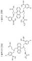
또한, 본 발명의 구체예에서 이용되는 바람직한 지시 단량체는 지시 분자의 산화에 대한 감수성을 감소시키기 위하여 전자흡인기(electron withdrawing group)를 포함하도록 설계된, 미국 특허 제7,851,225호에 기술된 것을 포함할 수 있다. 본 발명의 구체예에서, 아릴 보론산 잔기를 포함하는 지시 분자는 하나 이상의 전자흡인기를 보론산 잔기를 포함하는 방향족 모이어티에 첨가함으로써, 보로네이트 모이어티를 안정화시켜, 산화에 대해 더욱 내성을 갖도록 제조될 수 있다. 용어 "아릴(aryl)"은 페닐 화합물, 다핵성 방향족 화합물, 헤테로방향족 화합물, 다핵성 헤테로방향족 화합물 등과 같은, 광범위한 방향족 기(aromatic group)를 포함하는 것으로 이해될 것이다. 비-한정적 예는 페닐, 나프틸, 안트릴, 피리딜 등을 포함한다. 광범위한 전자흡인기가 본 발명의 범위 내에 속하고, 할로겐, 시아노, 니트로, 할로-치환(halo-substituted) 알킬, 카르복실산, 에스테르, 설폰산, 케톤, 알데히드, 설폰아마이드, 설폰, 설포닐, 설폭사이드, 할로-치환 설폰, 할로-치환 알콕시, 할로-치환 케톤, 아마이드 등, 또는 그의 조합을 포함하나 이에 한정되지 않는다. 가장 바람직하게는, 전자흡인기는 트리플루오로메틸이다. 본 발명의 구체예에서, 지시 분자의 전자흡인기는 하기 나타낸 지시 분자의 특정한 화학 구조 중 R1 및/또는 R2 위치를 차지한다:In addition, preferred indicator monomers used in embodiments of the present invention may include those described in US Pat. No. 7,851,225, which is designed to include an electron withdrawing group to reduce the susceptibility to oxidation of the indicator molecules. . In an embodiment of the invention, the indicator molecule comprising an aryl boronic acid residue is prepared to stabilize the boronate moiety by adding one or more electron withdrawing groups to the aromatic moiety comprising the boronic acid residue, thereby making it more resistant to oxidation. Can be. The term "aryl" will be understood to encompass a wide variety of aromatic groups, such as phenyl compounds, polynuclear aromatic compounds, heteroaromatic compounds, polynuclear heteroaromatic compounds, and the like. Non-limiting examples include phenyl, naphthyl, anthryl, pyridyl and the like. A wide range of electron withdrawing groups are within the scope of the present invention and include halogen, cyano, nitro, halo-substituted alkyl, carboxylic acid, ester, sulfonic acid, ketone, aldehyde, sulfonamide, sulfone, sulfonyl, Sulfoxides, halo-substituted sulfones, halo-substituted alkoxy, halo-substituted ketones, amides, and the like, or combinations thereof. Most preferably, the electron withdrawing group is trifluoromethyl. In an embodiment of the invention, the electron withdrawing group of the indicator molecule occupies the R1 and / or R2 position of the specific chemical structure of the indicator molecule shown below:

여기서, 각 "Ar"은 아릴 기이고; R1 및 R2 각각은 동일하거나 상이하고 전자흡인기이며; "m" 및 "n"은 각각 독립적으로 1 내지 10의 정수이고; R4는 검출가능한 모이어티이며; 및 각 R은 독립적으로, 0개 내지 10개의 인접한(contiguous) 또는 분지형 탄소 및/또는 헤테로원자를 갖는 결합기이고 하나 이상의 R은 추가로 중합성 단량체 단위를 갖는다. 특히 바람직한 구체예에서, 지시자는 도 2aa 내지 2bc에 도시된 하나 이상의 화합물을 포함한다. 또한, 지시 단량체 화합물 및 검출 시스템이 중합체 형태로 존재할 수 있다는 것이 상기 정의로부터 이해될 것이다.Wherein each "Ar" is an aryl group; Each of R1 and R2 is the same or different and is an electron withdrawing group; "m" and "n" are each independently an integer of 1 to 10; R4 is a detectable moiety; And each R is independently a linking group having from 0 to 10 contiguous or branched carbons and / or heteroatoms and at least one R further has a polymerizable monomer unit. In a particularly preferred embodiment, the indicator comprises one or more compounds shown in FIGS. 2A-2B. It will also be understood from the above definition that the indicated monomeric compound and the detection system may exist in polymer form.
본 명세서에 기술된 발명은 지시자를 보호할 수 있고, 도 2aa 내지 2bc에 상세히 나타낸 바람직한 구조에 한정되지 않는다는 것이 이해되어야 한다. 또한, 체내로 투여되는 기타의 물질 및 생물의약품(biologics)는 산화, 특히 ROS로 인한 산화에 의해 손상될 수 있다. 그와 같은 기타의 물질은 흡광형(absorbance type) 지시자, 단백질, 분자, 정형외과용 이식물, 미용 이식물, 심박조율기 와이어 등일 수 있다. 지시자 또는 구조가 퍼옥사이드/ROS에 의한 산화에 영향받기 쉬운 한, 본 명세서에 기술된 발명은 그와 같은 지시자 또는 구조를 보호할 것이다.It is to be understood that the invention described herein may protect the indicator and is not limited to the preferred structure shown in detail in FIGS. 2A-2B. In addition, other substances and biologics administered into the body can be damaged by oxidation, in particular by oxidation due to ROS. Such other materials may be absorbance type indicators, proteins, molecules, orthopedic implants, cosmetic implants, pacemaker wires, and the like. As long as the indicator or structure is susceptible to oxidation by peroxide / ROS, the invention described herein will protect such indicator or structure.
이식가능한 장치는 단지 그 장치의 삽입을 가능하게 하는 일정 크기의 피부의 파괴(breach)를 요한다. 본 발명의 일 구체예에서, 센서는 그것을 근육과 진피 사이의 피하 공간 내에 위치시키는 과정에서 피부를 통해 이식된다. 가장 작고 생체적합성이 가장 높은 장치의 경우에도, 이물질 침입의 결과로 국소 조직 및 인접 조직에 기계적 손상이 발생한다. 이는, 우선 장치가 피부를 관통해야 하고, 그 후 그의 의도된 생체 내 기능을 발휘하기 위해 조직을 치환(displace)하여, 장치가 배치되고 머무르게 될, 포켓 또는 공간을 형성해야 하기 때문이다. 센서의 상대적인 크기 및 이동(displacement) 이외의, 센서 그 자체의 상대적인 생체적합성은, 센서 또는 장치를 제자리에 놓기 위하여 국소 조직에 가해지는 최소의 손상에 영향을 미치지 않는다. 이물질 침입 및 국소 조직 손상의 결과, 즉각적이고 정상적인 염증 케스케이드(cascade)가 숙주를 보호하기 위한 목적으로 그 침입에 직접 반응하여 숙주 내에서 시작되고, 침입의 기계적 손상을 교정하기 위한 회복 과정을 즉시 시작한다, 즉 상처가 치유되기 시작한다.Implantable devices only require a break in the skin of some size to allow insertion of the device. In one embodiment of the invention, the sensor is implanted through the skin in the process of placing it in the subcutaneous space between the muscle and the dermis. Even for the smallest and most biocompatible devices, mechanical damage occurs to local and adjacent tissues as a result of foreign body intrusion. This is because the device must first penetrate the skin and then displace the tissue to exert its intended in vivo function to form a pocket or space in which the device will be placed and stayed. In addition to the relative size and displacement of the sensor, the relative biocompatibility of the sensor itself does not affect the minimal damage to local tissue to place the sensor or device in place. As a result of foreign body invasion and local tissue damage, an immediate and normal inflammatory cascade begins directly within the host in response to the invasion for the purpose of protecting the host and immediately initiates a recovery process to correct for mechanical damage of the invasion. The wound begins to heal.
센서가 동물, 및 보다 정확하게는 사람의 내부에 배치될 경우, 거의 즉각적인 생물학적 반응, 및 염증의 직접적인 결과로 신체에 의한 센서의 확대된 성능에 가해지는 손상이 존재한다는 것이 관찰된다. 염증에 의한 손상의 순 결과는, 예를 들면 신호 강도를 감소시킴으로써 장치의 유효 수명을 단축시키는 것이다. 기타의 장치에 있어서, 유효 수명의 감소는 반응 파울링(response fouling), 기계적 강도의 감소, 전기적 또는 기계적 단열 특성, (생체적합성에 영향을 미칠 수 있는) 표면 침식의 관점에서, 또는 기타 측정가능한 특성에 따라 측정될 수 있다.It is observed that when sensors are placed inside animals, and more precisely in humans, there is a damage that affects the expanded performance of the sensor by the body as a direct result of an almost immediate biological response, and inflammation. The net result of damage from inflammation is to shorten the useful life of the device, for example by reducing signal strength. In other devices, the reduction in useful life may be in terms of response fouling, reduction in mechanical strength, electrical or mechanical insulation properties, surface erosion (which may affect biocompatibility), or other measurable. It can be measured according to the characteristics.
염증 반응은 부분적으로는 손상에 직접 반응하여 발생하는 일시적인 상태로 구성된다. 장치를 이식한 결과 필연적으로 작은 조직 손상이 존재하고, ROS와 연관된 염증 반응의 특정의 양태는 이식된 장치에 부정적인 영향을 미칠 수 있다는 것이 관찰되었다. 또한, 일시적인 치유 기간 후, 센서 주변의 염증 상태가 유의하게 진정됨에도 불구하고, 이식된 장치에 대한 만성적인, 낮은 수준의 이물 반응이 존재한다.The inflammatory response consists in part in a transient state that occurs in direct response to injury. As a result of implanting the device, it has been observed that small tissue damage is inevitably present, and that certain aspects of the inflammatory response associated with ROS can negatively affect the implanted device. In addition, after a temporary healing period, there is a chronic, low level of foreign body response to the implanted device, despite the significant calm of the inflammatory state around the sensor.
상기-언급된 문제에 대한 해결책은 이식물의 영역에서 국소적으로 발생되는 ROS를 분해하는 물질, 구조, 및/또는 코팅을 이식된 장치의 표면상에 또는 그 주변에 적용하는 것이다. 일단 장치가 이식되면, 그 물질, 구조, 및/또는 코팅은 다공성 센서 이식물로 들어오는 ROS에 대한 화학적 장벽을 제공함으로써, 도 1b에 도시된 바와 같이, ROS가 산화를 통해 지시 시스템(indicator system)을 공격할 수 있는 것을 방지한다.The solution to the above-mentioned problem is to apply a material, structure, and / or coating on or around the surface of the implanted device that degrades ROS locally occurring in the area of the implant. Once the device is implanted, the material, structure, and / or coating provides a chemical barrier to the ROS entering the porous sensor implant, thereby allowing the ROS to oxidize through the indicator system, as shown in FIG. 1B. Prevents you from attacking.
본 발명의 구체예에서, 물질, 구조, 및/또는 코팅은, 예를 들면, 은, 팔라듐 또는 백금, 또는 그의 산화물과 같은, 생체 내 환경에서 충분히 무독성인, ROS (특히 과산화수소)의 분해를 촉매할 수 있는 생리적으로 적합한 금속 또는 금속 산화물을 포함할 수 있다. 생리적으로 적합한 금속이 본 발명의 구체예에서 코팅으로 구현되는 경우, 그 코팅은 스퍼터 증착에 의한 것과 같은, 적합한 방식으로 센서 물질에 적용될 수 있다. 상기 물질, 구조, 및/또는 코팅의 두께는 광범위하게, 예를 들면, 약 0.5 nm 내지 약 2.5 nm로 변할 수 있다. 본 발명의 추가의 구체예에서, 상기 물질, 구조, 및/또는 코팅의 두께는 약 1 nm 내지 20 nm 두께일 수 있다. 본 발명의 추가의 구체예에서, 상기 물질, 구조, 및/또는 코팅의 두께는 약 3 nm 내지 약 6 nm 두께일 수 있다.In embodiments of the invention, the material, structure, and / or coating catalyzes the decomposition of ROS (particularly hydrogen peroxide), which is sufficiently nontoxic in an in vivo environment, such as, for example, silver, palladium or platinum, or oxides thereof. Physiologically suitable metals or metal oxides as may be included. If a physiologically suitable metal is implemented as a coating in an embodiment of the invention, the coating may be applied to the sensor material in a suitable manner, such as by sputter deposition. The thickness of the material, structure, and / or coating can vary widely, for example, from about 0.5 nm to about 2.5 nm. In further embodiments of the invention, the thickness of the material, structure, and / or coating may be about 1 nm to 20 nm thick. In further embodiments of the invention, the thickness of the material, structure, and / or coating may be from about 3 nm to about 6 nm thick.
도 3은 신호가 이식된 글루코스 센서로부터 나올 경우, 장치 이식에 대한 생물학적 반응, 특히, ROS의 존재의 결과로서, 정규화된(normalized) 신호 상실의 예를 도시하는 그래프이다. 도 3의 데이터는, 세 명의 서로 다른 사람에게, 후방 손목(dorsal wrist) 영역의 피하 공간 내에 이식된 3개의 센서 (P06, P10, 및 P11로 표시)로부터 얻었다. 이 과정의 종결 후, 외부 와치 판독기(external watch reader)를 센서 위에 두어 센서와 외부 판독기 간의 데이터 소통을 가능하게 하였다. 이 센서로부터 4일에 걸쳐 신호 데이터를 수집하였다. 이식 과정 (과정 자체는 약 5분이 요구됨) 후 1일 내에 매우 신속하고 유의한 신호의 감소가 발생한 것을 도 3으로부터 확인할 수 있다. 정규화 스케일 상에서, 두 개의 센서에서의 신호는 24시간 후 실질적으로 100% 감소된 반면, 제3 센서로부터의 신호는 24시간 후 약 90% 감소하였다. 이 신호의 감소는 이식물의 전반적인 유효 수명을 단축시키므로 바람직하지 않다.FIG. 3 is a graph showing an example of normalized signal loss as a result of biological response to device implantation, in particular the presence of ROS, when the signal is from an implanted glucose sensor. The data in FIG. 3 were obtained from three sensors (labeled P06, P10, and P11) implanted in the subcutaneous space of the dorsal wrist region to three different persons. After the end of this process, an external watch reader was placed on the sensor to enable data communication between the sensor and the external reader. Signal data was collected from this sensor over four days. It can be seen from FIG. 3 that a very rapid and significant signal reduction occurred within 1 day after the transplantation procedure (process itself requires about 5 minutes). On the normalization scale, the signal from the two sensors decreased substantially 100% after 24 hours, while the signal from the third sensor decreased about 90% after 24 hours. Reduction of this signal is undesirable because it shortens the overall useful life of the implant.
본 발명의 구체예는 염증 반응과 연관된 ROS가, ROS가 존재할 수 있는 간극 공간 등에 배치된 센서 이식물에 손상을 입힐 수 있는 산화 메커니즘을 다룬다. 구체적으로, 본 발명의 구체예는 산화가 ROS에 의해 유발되는, 지시 고분자의 산화에 의한 신호의 상실을 다룬다. 사람 (및 동물)로부터 외식된(explanted) 센서의 분석은 활성산소종 공격의 구체적이고 결정적인 증거를 보여준다. 본 발명의 맥락에서, 외식된 센서는 생체 내로 이식된 후 그 생체로부터 제거된 센서 (또는 통상적으로 생물 조직이 아닌 외부 물질)이다. 외식된 센서는 생체로부터의 추출 후 외식체(explant)에 부착된 채 남아있는 생물학적 물질을 가질 수 있다. 상처 치유와 잠재적으로 연관된 산화제는, 손상에 반응하여 그 부위로 이동되는 국소적 회복 세포(local repair cell)로부터 생성되는 과산화수소, 수퍼옥사이드, 하이포클로라이트, 퍼옥시니트리트, 및 수산기 라디칼을 포함한다. 본 발명의 구체예에서 글루코스 센서로 작동하는, 지시 고분자에 가해지는 ROS에 의한 특정의 산화 반응의 손상이 도 1a에 나타난다.Embodiments of the present invention address oxidative mechanisms in which ROS associated with inflammatory responses can damage sensor implants disposed in gap spaces or the like in which ROS may be present. Specifically, embodiments of the present invention deal with the loss of signal by oxidation of the indicator polymer, where oxidation is caused by ROS. Analysis of sensors explanted from humans (and animals) shows specific and conclusive evidence of reactive oxygen species attack. In the context of the present invention, an explanted sensor is a sensor (or typically an external material that is not a biological tissue) that has been removed from the living body after being implanted in vivo. The explanted sensor may have biological material that remains attached to the explant after extraction from the living body. Oxidants potentially associated with wound healing include hydrogen peroxide, superoxide, hypochlorite, peroxynitrite, and hydroxyl radicals generated from local repair cells that are moved to the site in response to injury. . Damage to certain oxidation reactions by ROS applied to the indicator polymer, acting as a glucose sensor in an embodiment of the present invention, is shown in FIG.
도 1a는 본 발명과 관련하여 유용할 수 있는 하나의 글루코스 지시 분자 (단량체)의 생체 내 ROS 산화성 탈붕소화(oxidative deboronation) 반응을 나타내고, 호중구 회복 세포 메커니즘에 의해 생성된 ROS의 직접적인 결과로, 이 지시 시스템의 보로네이트 인식 요소가 수산기로 전환됨을 나타낸다. 지시 시스템의 보로네이트 인식 요소가 수산기로 산화된, 표준 지시 분자의 생체 내 변화된(altered) 지시 분자로의 전환은, 그 분자에서 활성의 완전한 상실 (구체적으로, 글루코스 농도에 의해 영향 받는 형광 변조)을 유발한다. 도 1a에 나타낸 바와 같은 반응에서 임계적 결합 에너지(critical bond energy)는: C-C = 358 kJ/mol; C-B = 323 kJ/mol; 및 B-O = 519 kJ/mol이다. 이들 결합 에너지는, 가장 낮은 결합 에너지를 갖는 탄소-붕소 결합이 산화에 의한 공격 및 절단에 가장 쉽게 영향받을 수 있다는 것을 암시한다. 이 분석은 Alizarin Red 분석 (보로네이트에 대해 음성)에 의해, 및 추가적으로 확대된 동물 검사(extended animal testing)로부터 외식된 센서에 대한 Gibbs 검사 (페놀에 대해 양성)로부터 확인된다. 지시 분자로부터 보로네이트의 상실은 직접적으로 형광 신호 변조의 상실을 초래한다.1A shows the in vivo ROS oxidative deboronation reaction of one glucose indicating molecule (monomer) that may be useful in connection with the present invention and is a direct result of ROS produced by the neutrophil repair cellular mechanism, It indicates that the boronate recognition element of this pointing system is converted to a hydroxyl group. The conversion of a standard indicator molecule into an altered indicator molecule in vivo, in which the boronate recognition element of the indicator system is oxidized to a hydroxyl group, results in complete loss of activity in that molecule (specifically, fluorescence modulation affected by glucose concentration). Cause. The critical bond energy in the reaction as shown in FIG. 1A is: C-C = 358 kJ / mol; C-B = 323 kJ / mol; And B-O = 519 kJ / mol. These binding energies suggest that the carbon-boron bonds with the lowest binding energy can be most easily affected by attack and cleavage by oxidation. This assay is confirmed by Alizarin Red assay (negative for boronate) and from Gibbs test (positive for phenol) on sensors explanted from extended animal testing. Loss of boronate from the indicator molecule directly leads to loss of fluorescence signal modulation.
전술한 바와 같이, ROS에 의해 유도된 산화는 센서를 피부 아래에 이식하는 자극 및 국소 조직에 수반되는 파괴와 소규모 손상의 결과로 얻어지는 정상적인 치유 염증(healing inflammation)의 결과이다. 지시 고분자가 하나 이상의 보론산 인식 요소를 포함할 경우, ROS에 의해 유도된 산화는 탈붕소화를 유발하여 지시 고분자로부터 신호의 상실을 초래하고, 그에 의해 센서의 유효 수명을 단축시킨다. 또한, ROS에 의해 유도된 산화는 기타의 유사하게 영향받기 쉬운 장치 또는 물질의 유효 수명을 단축시킬 수 있다. 과산화수소는 이식물의 지시 고분자를 산화시키는 가능성이 가장 높은 ROS 종으로 확인되었다.As mentioned above, oxidation induced by ROS is the result of normal healing inflammation resulting from the stimulation of implanting the sensor under the skin and the destruction and minor damage associated with local tissue. If the indicator polymer contains one or more boronic acid recognition elements, oxidation induced by ROS causes deboronization, resulting in loss of signal from the indicator polymer, thereby shortening the useful life of the sensor. Oxidation induced by ROS can also shorten the useful life of other similarly susceptible devices or materials. Hydrogen peroxide was identified as the ROS species most likely to oxidize the indicator polymer of the implant.
그러나, 과산화수소의 산소와 물로의 분해는 하기와 같이 금속성 은에 의해 촉매된다:However, the decomposition of hydrogen peroxide into oxygen and water is catalyzed by metallic silver as follows:
금속성 은에 의한 과산화수소의 촉매에 의한 분해 Catalytic Decomposition of Hydrogen Peroxide by Metallic Silver

열역학적으로 우세함(favored) Thermodynamically favored
하기 기술된 실험은, 금속성 은이 어떻게 과산화물이 센서의 생체 내 기능성을 파괴할 수 있는 것보다 더 빠르게 과산화수소를 분해함으로써 지시 이식물을 보호하는 방식으로 본 발명의 일 구체예에 따른 센서 상에 설치되거나 센서 내에 배열되는지를 결정하기 위해 수행되었다. 또한, 팔라듐 및 백금을 포함한 기타 금속을 과산화수소에 대한 유사한 활성 및 본 발명의 일 구체예에 따른 센서와의 통합에 대해서 연구하였다. 도 1b는 본 발명의 구체예에 따라, 과산화수소의 분해를 촉매하는 금속의 존재로 인해, ROS로부터 유래된 산화성 탈붕소화 반응으로부터 본 발명과의 관계에서 유용할 수 있는 하나의 글루코스 지시 분자의 생체 내 보호를 나타낸다. 또한, 촉매 반응에 의해 과산화수소를 분해하는 금속의 산화물이 본 발명의 구체예에 있어서 적합할 수 있다.The experiments described below may be installed on a sensor according to one embodiment of the present invention in a manner in which metallic silver protects the indicator implant by decomposing hydrogen peroxide faster than how the peroxide can destroy the in vivo functionality of the sensor. This was done to determine if it was arranged in the sensor. In addition, other metals, including palladium and platinum, have been studied for similar activity against hydrogen peroxide and integration with sensors according to one embodiment of the invention. FIG. 1B shows a biomarker of one glucose indicating molecule that may be useful in a relationship with the present invention from an oxidative deboration reaction derived from ROS, due to the presence of a metal that catalyzes the decomposition of hydrogen peroxide, in accordance with an embodiment of the present invention. Indicates my protection In addition, oxides of metals that decompose hydrogen peroxide by catalytic reaction may be suitable in embodiments of the present invention.
본 발명의 일 구체예는, ROS로부터 유래된 산화의 효과로부터 장치를 보호하는 보호층을 포함하는 이식가능한 장치이다. 구체예에서, 이 장치는 목적 분석 물질에 민감한 이식물 내에 내장된(embedded) 지시 고분자를 가질 수 있는 다공성 센서 이식물에 적어도 부분적으로 매입된(encased) 센서일 수 있다. 바람직한 구체예에서, 지시 고분자는 글루코스의 존재에 민감할 수 있다. 구체예에서, 보호층은 ROS가 이식가능한 장치의 기타 구성요소와 반응할 수 있기 전, ROS의 분해를 촉매하는 금속으로 구성된다. 일부 구체예에서, 보호층의 금속은 은, 백금, 팔라듐, 망간, 및/또는 그의 합금 또는 금-함유 합금으로 구성된다. 일부 구체예에서, 보호층은 장치의 적어도 일부를 둘러싸는 와이어, 메쉬, 또는 기타 구조 용기(structural encasement)의 형태일 수 있다. 다른 구체예에서, 보호층은 장치의 적어도 일부 상에 스퍼터-증착된(sputter-deposited) 코팅의 형태일 수 있다. 이들 비-한정적인 구체예가 하기 기재된 예시적인 구체예로 이용된다.One embodiment of the invention is an implantable device comprising a protective layer that protects the device from the effects of oxidation derived from ROS. In an embodiment, the device may be a sensor that is at least partially encased in a porous sensor implant that may have an indicator polymer embedded in an implant that is sensitive to the analyte of interest. In a preferred embodiment, the indicator polymer can be sensitive to the presence of glucose. In an embodiment, the protective layer consists of a metal that catalyzes the degradation of the ROS before the ROS can react with other components of the implantable device. In some embodiments, the metal of the protective layer is composed of silver, platinum, palladium, manganese, and / or alloys or gold-containing alloys thereof. In some embodiments, the protective layer may be in the form of a wire, mesh, or other structural encasement surrounding at least a portion of the device. In other embodiments, the protective layer may be in the form of a sputter-deposited coating on at least a portion of the device. These non-limiting embodiments are used in the exemplary embodiments described below.
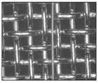
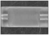
본 발명의 일 구체예에서, 금속성 은은 센서 이식물과 외부 환경 사이에 배치되어, 과산화수소가, 메쉬와 같은, 다공성 촉매 장벽을 통해 확산되는 것이 요구되고, 따라서 지시 분자와의 반응 전에 물과 산소로 분해될 것이다. 과산화수소를 분해하기 위한 은의 효능을 도 4a에 나타낸 바와 같이, 180 × 180 마이크론의 순은 메쉬(pure silver mesh)를 이용하여 시험하였다. (이 메쉬에 대해 사용된 값은 와이어/인치를 의미한다. 또한, 도 4a는 스케일을 제공하기 위하여 은 메쉬와 함께 25 마이크론 두께(직경)의 금 와이어를 나타낸다.) 도 4b는 본 발명의 일 구체예에 따라, 메쉬(403) 및 메쉬(403)가 어떻게, 다공성 센서 이식물(402)의 영역을 갖는 센서(401)의 주위에 맞춰지는지에 대한 도시이다. 도 4c는 본 발명의 일 구체예에 따라 사용된 메쉬의 측면도 및 단면도(end view)에 대한 추가의 도시이다.In one embodiment of the present invention, metallic silver is disposed between the sensor implant and the external environment such that hydrogen peroxide is required to diffuse through the porous catalyst barrier, such as a mesh, and thus with water and oxygen prior to reaction with the indicator molecule. Will be disassembled. The efficacy of silver to degrade hydrogen peroxide was tested using a pure silver mesh of 180 × 180 microns, as shown in FIG. 4A. (The values used for this mesh refer to wires / inch. Also, Figure 4A shows a 25 micron thick (diameter) gold wire with a silver mesh to provide scale.) Figure 4B illustrates one aspect of the present invention. According to an embodiment, it is shown how
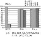
과산화수소에 대한 은 메쉬의 촉매 효과를 시험하기 위하여, 자일레놀 오렌지를 함유한 4개의 시료 (시료 A, B, C, 및 D)를 하기 설명된 바와 같이 시험하였다. 검출은 자일레놀 오렌지의 존재하에서 철의 철 이온으로의 산화에 기초하고, 용액 중 과산화수소를 포함하지 않은 시료가 투명하고 오렌지 색으로 보인다. 과산화수소가 자일레놀 오렌지와 함께 존재하는 경우, 용액은 자주색이고 불투명하게 보인다. 시료 (A)는 과산화수소가 첨가되지 않은 대조군이었다. 시료 (B)는 은을 포함하지 않고 0.2 mM 과산화수소를 포함하였다; 이 시료 중 과산화수소는 용액을 자주색이고 불투명하게 하였다. 시료 (C)는 30분 동안 은 메쉬를 포함한 0.2 mM 과산화수소를 포함하였다. 시료 (B)에 비하여, 시료 (C)는 보다 투명하고 밝은 색을 띠어서, 시료 (C)의 용액 중 과산화수소의 양이 감소되었음을 나타내었다. 시료 (D)는 60분 동안 은 메쉬를 포함한 0.2 mM 과산화수소를 포함하였다. 시료 (D)는 오렌지 색을 띠고 투명하며 대조군인 시료 (A)와 동일하게 보여서, 시료 (D) 용액 중 남아있는 과산화수소가 존재하지 않음을 나타내었다.In order to test the catalytic effect of silver mesh on hydrogen peroxide, four samples containing xenol orange (Samples A, B, C, and D) were tested as described below. Detection is based on the oxidation of iron to iron ions in the presence of xenol orange, and the sample without hydrogen peroxide in solution appears transparent and orange in color. If hydrogen peroxide is present with the xenol orange, the solution appears purple and opaque. Sample (A) was a control without hydrogen peroxide added. Sample (B) did not contain silver and contained 0.2 mM hydrogen peroxide; Hydrogen peroxide in this sample made the solution purple and opaque. Sample (C) contained 0.2 mM hydrogen peroxide with a silver mesh for 30 minutes. Compared to sample (B), sample (C) was more transparent and brighter, indicating that the amount of hydrogen peroxide in the solution of sample (C) was reduced. Sample (D) contained 0.2 mM hydrogen peroxide with a silver mesh for 60 minutes. Sample (D) was orange, transparent and looked the same as control (A), indicating that there was no hydrogen peroxide remaining in the sample (D) solution.
도 5a는 시료 (A), (B), (C), 및 (D)에 대한 가시광선 스펙트럼에서의 흡수 프로파일을 나타낸다. 주목할만한 것은, 60분 동안 은에 노출시킨 0.2 mM의 과산화수소인, 시료 (D)의 흡수 프로파일이 과산화수소를 포함하지 않은 대조군 시료 (A)의 흡수 프로파일과 거의 동일하다는 점이다.5A shows absorption profiles in the visible light spectrum for samples (A), (B), (C), and (D). Notably, the absorption profile of sample (D), 0.2 mM hydrogen peroxide exposed to silver for 60 minutes, is nearly identical to the absorption profile of control sample (A) without hydrogen peroxide.
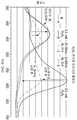
도 5b는 물에서 과산화수소의 은 메쉬에 의한 인 비트로 분해 프로파일과, 인체 이식 부위에서 측정된 과산화수소의 인 비보 생성 프로파일 간 비교를 나타낸다. 이 인 비트로 분해 프로파일은 pH 약 7인 물 중 0.2 mM 과산화수소 1.5 mL 내에 있는 약 60 mg의 은 메쉬의 것이다. 두 프로파일을 비교하면, 180 × 180의 순은 메쉬와 같은 은 촉매를 사용한 과산화수소 분해 속도가, 사람의 제1형 당뇨병 상처 치유에서 측정된 과산화수소의 인 비보 생성 속도보다 약 7배 빠르다는 것이 명백하다.5B shows a comparison between the in vitro degradation profile by the silver mesh of hydrogen peroxide in water and the in vivo production profile of hydrogen peroxide measured at the site of human implantation. This in vitro degradation profile is about 60 mg of silver mesh in 1.5 mL of 0.2 mM hydrogen peroxide in water at pH about 7. Comparing the two profiles, it is evident that the rate of hydrogen peroxide degradation using a silver catalyst such as a 180 × 180 pure silver mesh is about seven times faster than the in vivo production rate of hydrogen peroxide measured in
과산화수소를 물과 산소로 분해하는 데 있어서 은의 촉매 활성은 매우 효과적이어서, 이와 같은 목적을 위해 이식가능한 장치와 함께 사용되는 은이, 이식물과 근접해 있기만 한 경우에도 여전히 효과적일 것이다. 다시 말해서, 은은 장치의 구조에 반드시 결합되거나 포함될 필요는 없다. 그러나, 과산화수소를 분해하는 은의 인 비트로 촉매 활성은 염소 이온에 의해 억제될 수 있다는 것이 알려져 있다. 염소에 의한 은의 이와 같은 억제는 은 촉매 피독(silver catalyst poisoning)으로 지칭될 수 있다.The catalytic activity of silver in the decomposition of hydrogen peroxide into water and oxygen is so effective that silver used with implantable devices for this purpose will still be effective if it is in close proximity to the implant. In other words, silver does not necessarily need to be combined or included in the structure of the device. However, it is known that the in vitro catalytic activity of silver which decomposes hydrogen peroxide can be suppressed by chlorine ions. Such inhibition of silver by chlorine may be referred to as silver catalyst poisoning.
또한, 팔라듐 및 백금과 같은 기타의 금속은 상이한 속도 및 효율 및 반응속도(kinetic) 프로파일로 과산화수소를 분해한다. 본 발명의 발명자는 팔라듐 또는 백금 어느 것도 염소에 의해 피독되거나 혈청 알부민 (70 mg/ml 이상)의 높은 단백질 농도에 의해 억제되지 않았다는 것을 발견하였다. 은과 유사하게, 팔라듐과 백금 또한, 신체가 과산화수소를 생성할 수 있는 것보다 빠른 속도로 과산화수소를 분해하고, 이식가능한 장치에 근접하여, 과산화수소가 그 장치에 도달하고 및/또는 손상시키는 것을 방지하는 데 있어서 효과적이다. 대안적으로, 은, 팔라듐, 백금, 금 또는 그의 조합의 합금 또는 그의 산화물이 과산화수소의 산소와 물로의 분해를 촉매하는 데 이용될 수 있다. 본 발명의 맥락에서, 근접(close proximity)은 장치 및/또는 물질이 의도된 방식으로 기능할 수 있게 하는 충분히 가까운 거리이다. 근접한 것으로서 인정되는 거리 또는 두께의 범위는, 구조적 구체예(structural embodiment)의 구조 및 배열에 따라, 변할 것이다. 일반적으로, 근접의 범위는 약 2.5 mm 이하일 것이다. 본 발명의 구체예에서, 센서를 보호하기 위해 이용되는 구조는 센서 몸체를 완전히 둘러싸거나 봉입할 필요는 없으나, 센서의 지시 영역을 보호하도록 구현되어야 한다.In addition, other metals, such as palladium and platinum, decompose hydrogen peroxide with different rates and efficiencies and kinetic profiles. The inventors of the present invention found that neither palladium or platinum was poisoned by chlorine or inhibited by the high protein concentration of serum albumin (70 mg / ml or more). Similar to silver, palladium and platinum also decompose hydrogen peroxide at a faster rate than the body can produce hydrogen peroxide, and in proximity to the implantable device, preventing hydrogen peroxide from reaching and / or damaging the device. Effective in Alternatively, alloys of silver, palladium, platinum, gold or combinations thereof or oxides thereof may be used to catalyze the decomposition of hydrogen peroxide into oxygen and water. In the context of the present invention, close proximity is a close enough distance to allow the device and / or material to function in the intended manner. The range of distances or thicknesses recognized as close will vary depending upon the structure and arrangement of the structural embodiments. In general, the range of proximity will be about 2.5 mm or less. In an embodiment of the invention, the structure used to protect the sensor need not completely surround or enclose the sensor body, but should be implemented to protect the pointing area of the sensor.
백금과 팔라듐 시료를 인산염 완충 염수(PBS) 중 0.2 mM 과산화수소의 용액에 수 시간 동안 37℃에서 각각 두었다. 시료는 본 발명의 일 구체예에 따른 센서 중심(sensor core)의 막 이식물 영역 상에 배치되고(slid) 순수 금속 와이어로 싸인 백금 메쉬 및 팔라듐 코일이었다. 이 실험은 각 시도(trial)마다 도입된 신선한 과산화수소로, 여러 상이한 시료에 의해 반복되었다. 백금과 팔라듐 시료는 용액 중의 과산화수소를 완전히 분해하였다. 본 발명의 일부 구체예에서, 백금과 팔라듐은 금속 촉매를 센서 내로 포함시키는 구조를 설계하는데 이용되는 바람직한 금속이다. 이와 같은 구조는 장치 표면으로부터 측정된, 약 2.5 mm 이하의 두께일 수 있다.Platinum and palladium samples were each placed in a solution of 0.2 mM hydrogen peroxide in phosphate buffered saline (PBS) at 37 ° C. for several hours. The sample was a platinum mesh and a palladium coil wrapped on pure metal wire and slid on the membrane implant region of the sensor core according to one embodiment of the invention. This experiment was repeated with several different samples with fresh hydrogen peroxide introduced in each trial. Platinum and palladium samples completely decomposed hydrogen peroxide in the solution. In some embodiments of the present invention, platinum and palladium are preferred metals used to design structures that incorporate a metal catalyst into the sensor. Such a structure can be up to about 2.5 mm thick, measured from the device surface.
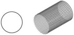
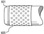
도 6a 및 6b는 본 발명의 구체예에 따른, 센서 중심(601)에 감긴 와이어(602)의 측면도 및 단면도를 도시한다. 도 6c 및 6d는 본 발명의 구체예에 따른, 센서 중심(601)에 감긴 메쉬(603)를 도시한다. 비-제한적인 구체예에서, 와이어와 메쉬는 코일 또는 실린더 배열로 감기고(wrap) 센서로 연결되어(slip over), 글루코스와 같은 분석 물질이 코일 또는 메쉬의 틈 사이로 확산될 수 있게 한다. 코일 또는 메쉬 형태의 금속 또는 금속 산화물 외에, 본 발명의 구체예에서 고려된 기타의 구조적 배열은, 도 6e에서와 같은 천공형(perforated) 또는 슬롯형(slotted) 용기(604), 도 6f에서와 같은 천공형 또는 슬롯형 호일(605), 도 6g에서와 같은 천공형 또는 슬롯형 재킷(jacket)(606), 도 6h에서와 같은 링 또는 부분 링(partial ring)(607), 도 6i에서와 같은 위브(weave) 또는 첩직(Dutch weave)(608), 도 6j에서와 같은 지그-재그 패턴의 메쉬(609), 및 금속 및/또는 금속 산화물 와이어 및/또는 리본, 또는 기타 형태의 원료(material stock)로 제조된 기타 그와 같은 구조이다. 이들 구조는, 과산화수소가 이식가능한 센서의 이식물 내로 확산되려고 할 경우, 주위에 있는 과산화수소가 금속상에서 반응하도록 설계된다. 본 발명의 바람직한 구체예에서, 설계는, 주변 과산화수소에 의한 산화로부터 이식물 지시 고분자를 보호하기 위하여, 외부 환경에 노출되는 금속의 표면적을 증가시키고, 이식가능한 센서의 이식물 표면을 덮는 충분한 밀도의 세공(pore), 틈(gap), 및/또는 다공(perforation)을 갖는 확산층이 되도록 의도된다.6A and 6B show side and cross-sectional views of
본 발명의 대안적인 구체예는, 다공성 센서 이식물 내에 현탁된(suspended), (본 명세서에 개시된) 과산화수소의 분해를 촉매하는 금속의 나노입자 형태를 이용할 수 있다. 비-제한적인 일 구체예에서, 다공성 센서 이식재의 형성은, 나노입자 금속이 첨가될 수 있는 겔 현탁액을 포함할 수 있다. 일단 장치의 일부로 형성되면, 이식물 내에 포획된 나노입자 금속을 갖는 다공성 센서 이식물은 지시 분자와 같은, 센서 이식물 및 장치의 기타 구성요소의, ROS에 의해 유도된 산화를 방지하기 위해 작동할 수 있다. 본 발명의 구체예에서, 나노입자 금속은 다공성 센서 이식물 전체에 균일하게 분포될 수 있고 및/또는 이식물 내에 미세-국재화(micro-localized)될 수 있다. 본 발명의 비-제한적인 일 구체예에서, 이 나노입자 금속은 직경이 80 nm 이하일 수 있다.Alternative embodiments of the present invention may utilize nanoparticle forms of metals that catalyze the decomposition of hydrogen peroxide (disclosed herein) suspended in a porous sensor implant. In one non-limiting embodiment, the formation of the porous sensor implant can include a gel suspension to which nanoparticle metal can be added. Once formed as part of the device, the porous sensor implant with nanoparticle metal trapped in the implant may act to prevent ROS induced oxidation of the sensor implant and other components of the device, such as indicator molecules. Can be. In an embodiment of the invention, the nanoparticle metal may be uniformly distributed throughout the porous sensor implant and / or micro-localized within the implant. In one non-limiting embodiment of the invention, the nanoparticle metal can be up to 80 nm in diameter.
구조 용기 (예를 들면, 와이어, 메쉬, 시스(sheath) 등)을 이용하는 구체예는, 이식가능한 장치의 매우 작은 크기로 인해, 과산화수소에 의한 산화적 분해로부터 이식가능한 장치를 보호하는데 성공적인 반면, 그와 같은 보호용 구조가 이식물과 외측 용액 (및 조직) 간 장벽과 같은 장치상에 기계적으로 설치되기 곤란하거나 어려울 수 있다는 것이 인식된다. 또한, 그와 같은 구조 용기(encasing)의 이용은, 특히 백금 및 팔라듐 물질의 경우 고가일 수 있다. 또한, 이식가능한 장치에 포함되는 구조에 요구되는, 주변 효과(edge effects), 표면 형태학, 및 작은 크기의 제작 품질(fabrication quality)은 구조 용기에 관련된 문제일 수 있다. 또한, 과산화수소의 촉매화는 금속의 표면에서 발생하고, 과산화수소 원자의 크기에 비하여, 구조적 구체예에서 고려되는 금속의 양은 과산화수소의 원하는 분해를 달성하기 위해 이론적으로 요구될 수 있는 것보다 큰 규모(orders of magnitude)일 수 있다. 또한, 조직이 코일, 메쉬, 위브 등의 공간으로 성장할 수도 있고, 센서의 잠재적인 제거를 보다 지루하고 국소 조직에 일정 정도 손상을 미치게 할 수 있다는 우려가 있다. 그러나, 이는 구조 용기를 이용하는 구체예가 ROS에 의해 유도된 산화와 관련된 전술된 문제에 대한 실행가능하고 강력한 해결책이 아니라는 점을 암시하는 것을 의미하지는 않는다. 반대로, 그들은 매우 효과적인 것으로 확인되었다.Embodiments using rescue vessels (eg, wires, meshes, sheaths, etc.) have been successful in protecting implantable devices from oxidative degradation by hydrogen peroxide, due to their very small size. It is appreciated that a protective structure such as may be difficult or difficult to mechanically install on a device such as a barrier between an implant and an outer solution (and tissue). In addition, the use of such structural casings can be expensive, especially for platinum and palladium materials. In addition, edge effects, surface morphology, and small-scale fabrication quality, which are required for structures included in implantable devices, can be a problem with structural containers. In addition, the catalysis of hydrogen peroxide occurs at the surface of the metal, and relative to the size of the hydrogen peroxide atom, the amount of metal contemplated in the structural embodiments is orders of magnitude larger than what might be theoretically required to achieve the desired decomposition of hydrogen peroxide. of magnitude). In addition, there is a concern that tissue may grow into spaces such as coils, meshes, weaves, etc., and that potential removal of the sensor may be more tedious and cause some damage to local tissue. However, this does not imply that embodiments using rescue vessels are not a viable and powerful solution to the aforementioned problems associated with oxidation induced by ROS. On the contrary, they have been found to be very effective.
본 발명의 다른 구체예에서, 보호용 금속이 스퍼터 코팅 기법을 이용하여 다공성 센서 이식물에 적용될 수 있다. 예를 들면, 이 기법은 은, 백금, 팔라듐, 망간, 금, 및 그의 합금 및/또는 산화물을 포함하는 스퍼터링 표적(sputtering target)을 이용할 수 있다. 금속 또는 금속 산화물에 의해 스퍼터 코팅된 센서 이식물은 센서 이식물 내로 분석 물질을 통과시킬 수 있도록 충분히 다공성을 유지해야 하지만, 센서 이식물 내로의 과산화수소의 확산에 대한 보호용 장벽으로서 여전히 효과적으로 작용해야 한다. 본 발명의 구체예에서, 촉매로 작용하는 금속 또는 금속 산화물은, 외계 및 내부 이식물 간의 약간 구불구불한(tortuous) 확산층으로 배열될 수 있어서, 높은 농도 및 빠른 생리적 생성 속도의 과산화수소로부터도 지시자를 보호한다. 또한, 약간 구불구불한 확산층은 영구적으로 선택적인 촉매성 장벽(permanently selective catalytic barrier)으로 특징지어질 수 있다. 스퍼터 증착(sputter deposition)은 물질을 금속원 또는 "표적"으로부터 스퍼터링, 즉 토출(ejecting)한 후, 그 표적으로부터의 원자를 기질 상에 증착시킴으로써 얇은 금속 필름을 증착시키는 잘 알려진 방법이다. 일반적으로, 진공-밀폐 환경 내에서, 고에너지 이온화 가스는 플라스마를 형성하고 표적을 향해 투사되어(projected) 금속 표적의 원자를 그 표적으로부터 분리시킨다(broken off). 표적으로부터 제거된(dislodged) 금속 원자가 기질 상에 증착될 경우, 그 금속의 얇은 막이 기질 상에 형성되고 기질과 결합한다. 표적에 대한 투사에 사용되는 가스 및 표적 자체의 조성에 따라서, 기질 상에 증착되는 금속 필름은 순 금속, 합금, 산화물, 질화물, 산질화물 등일 수 있다. 도 7은 스퍼터 코팅 챔버의 일반적인 표현이다.In another embodiment of the invention, a protective metal may be applied to the porous sensor implant using sputter coating techniques. For example, this technique may utilize a sputtering target comprising silver, platinum, palladium, manganese, gold, and alloys and / or oxides thereof. Sensor implants sputter-coated with metal or metal oxides must remain porous enough to allow analyte to pass into the sensor implant, but still function effectively as a protective barrier against the diffusion of hydrogen peroxide into the sensor implant. In embodiments of the present invention, the metal or metal oxide serving as a catalyst may be arranged in a slightly tortuous diffusion layer between the outer and inner implants, thus indicating the indicator even from hydrogen peroxide at high concentrations and fast physiological production rates. Protect. In addition, the slightly serpentine diffusion layer can be characterized as a permanently selective catalytic barrier. Sputter deposition is a well known method of depositing thin metal films by sputtering, ie, ejecting, material from a metal source or "target" and then depositing atoms from the target onto the substrate. In general, in a vacuum-sealed environment, high energy ionizing gases form plasma and are projected towards a target to break off atoms of the metal target from the target. When dislodged metal atoms are deposited on a substrate, a thin film of the metal forms on the substrate and binds to the substrate. Depending on the gas used to project the target and the composition of the target itself, the metal film deposited on the substrate may be pure metal, alloy, oxide, nitride, oxynitride, or the like. 7 is a general representation of a sputter coating chamber.
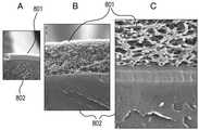
다공성 센서 이식물상으로의 스퍼터 증착의 초기 검사를 위해 금 표적을 이용하였다. 도 8A 내지 C는 금으로 스퍼터 코팅된 센서 이식물의, 배율 증가에 따른, 3개의 SEM 이미지이다. 다공성 센서 이식재 자체는 정상적으로는 SEM에 의해 가시적이지 않다. 사진 속 이미지는, SEM 하에서 가시적인, 하이드록시에틸메타크릴레이트 (hydroxyethylmethacrylate; HEMA) 공중합체 이식물(801)의 표면상에 스퍼터링된 금속성 금의 이미지이다. 따라서, 이들 사진은 단지, 금 표적을 이용한 스퍼터 증착 후 이식물 요소 표면을 덮은 금속성 금 쉘(shell)의 사진이다. 도 8A 내지 C에서 이용된 센서 이식물(801)은 절단된 후 스퍼터링되어, 이식물 막의 단면 이미지 및 풀 깊이(full depth)를 SEM 하에서 관찰할 수 있었다. 만일 단지 외측으로부터 스퍼터링된 후 절단되고, 그 후 SEM 이미지화되었다면, 예상되는 이미지는 하부의 비가시적인(invisible) 유기 이식물 층 위에 배치된(riding atop) 금속성 다공성 얇은 층일 것이다. 이식물 영역에서 가시적인 금속성 금 층은, 매우 얇고 (수 nm), 최소한 다공성 이식물 자체의 표면적과 일치하는 매우 큰 표면적을 갖는다. 금속에 의한 이식물(801)의 스퍼터 코팅은 이식물의 마크로-기공성(macro-porosity)을 방해하거나(clog) 또는 막지(foul) 않는다; 즉, 목적 분석 물질이 여전히 지시 분자를 통해 확산되고 이와 상호작용할 수 있을 것이다. 본 발명의 구체예에서, 센서를 보호하는데 이용되는 코팅은 센서 몸체(802)를 완전히 둘러싸거나 봉입할 필요도, 센서 상에 존재하는 다공성 이식물(801)의 전체 부분(entire portion)을 덮을 필요도 없으나, 다만 센서의 지시 영역을 보호하도록 구현될 필요는 있다.Gold targets were used for initial testing of sputter deposition onto porous sensor implants. 8A-C are three SEM images with increasing magnification of sensor implants sputter coated with gold. The porous sensor implant itself is normally not visible by SEM. The image in the photograph is an image of metallic gold sputtered onto the surface of the hydroxyethylmethacrylate (HEMA)
도 9는 센서 몸체의 내부 지향적인, 이식물의 외측 표면으로부터의 SEM 사진이다. 또한, 이 이미지는 엄밀히 말해 이식물의 이미지가 아니고, 이식물을 SEM에 의해 가시화되도록 하는, 이식물 상에 스퍼터링된 금속성 금의 이미지이다. 이 이미지는, 가시적인 이식물의 전체 표면적이 효과적으로 금에 의해 코팅됨을 나타낸다. 따라서, 노출된 금속의 표면적이 적어도 이식물의 표면적에 상당한다는(equivalent) 것을 추론할 수 있다. 전술된 도 6a의 구체예는 400 마이크론 직경의 팔라듐 와이어 코일을 이용하고, 외경(outside diameter) 주위를 감은 과산화수소에 대한 탁월한 보호를 나타내었다. 다공성 센서 이식물 상으로의 금속의 스퍼터 코팅은 와이어 코일보다 더 큰 표면적을 갖는다. 이는, 다공성 센서 이식물 상에 스퍼터 코팅된 금속의 보호 능력이 상기 논의된 발명의 구조 용기를 이용하는 구체예보다 우수할 수 있다는 것을 암시한다.FIG. 9 is a SEM photograph from the outer surface of the implant, inwardly facing the sensor body. FIG. Also, this image is not strictly an image of the implant, but an image of metallic gold sputtered onto the implant, causing the implant to be visualized by SEM. This image shows that the entire surface area of the visible implant is effectively coated by gold. Thus, one can infer that the surface area of the exposed metal is at least equivalent to the surface area of the implant. The above-described embodiment of FIG. 6A employs a 400 micron diameter palladium wire coil and exhibits excellent protection against hydrogen peroxide wrapped around an outside diameter. The sputter coating of metal onto the porous sensor implant has a larger surface area than the wire coils. This suggests that the protective ability of sputter coated metals on porous sensor implants may be superior to embodiments utilizing the structural vessels of the invention discussed above.
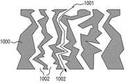
도 10a는 본 발명의 일 구체예에 따른, 센서 몸체(1003)의 외측 구조의 일부일 수 있는, 다공성 센서 이식물을 포함하는 구불구불한 막 구조(1000)의 도시이다. 용질(1001)은 막(1000)을 통과하고 가로지르기 위해 구불구불한 확산 통로(1002)를 따라야 한다. 도 10b는, 또한 다공성 센서 이식물(1000)에 표시된 지시 분자(1005)를 갖는, 금속화된 표면층(1004)을 갖는 구불구불한 막(1000)의 도시이다. 이것은 구불구불한 확산 장벽을 형성함에도 불구하고, 마크로세공은 여전히 약 1 마이크론이고, 금속 오염(metal fouling) 없이 활짝 열려있다. 구체예에서, 스퍼터링된 다공성 센서 이식물의 깊이는 마이크로 수준의 시선에 제한된다. 표적으로부터 스퍼터링된 금속은, 스퍼터링된 금속이 충돌 후 증착(deposits upon impact)하므로, 통상적으로 구불구불한 막 구조로 깊게 확산될 수 없고, 따라서 도 10b에 나타낸 바와 같이, 그림자 진 표면 아래 영역은 코팅되지 않은 채 남아있다. 본 발명의 일부 구체예에서, 다공성 센서 이식물 내로 금속화된 층(1004)의 두께는 5 마이크론 이하일 수 있다. 다른 구체예에서, 추가의 압력이 스퍼터링 환경에 도입될 수 있거나, 자기장이 이용될 수 있거나, 또는 기타의 방법이 이용되어 구불구불한 막(1000)이 가시선 증착의 지점(point of line of sight deposition)을 지나 스퍼터링되도록 함으로써, 금속화된 층(1004)이 다공성 센서 이식물의 풀 깊이를 통해 아래로 확장될 수 있다. 전술한 바와 같이, 센서 이식물은 스퍼터 증착 후 다공성으로 남아있다.10A is an illustration of a
본 발명의 특정의 구체예에서, 다공성 센서 이식물의 풀 깊이는 약 100 마이크론이다. 금속에 의해 스퍼터 코팅된 다공성 센서 이식물의 표면적은 스퍼터링된 금속에 의해 덮인 지시 분자의 기능을 상실할 것으로 예상된다. 그러나, 그와 같은 구체예에서, 약 상부 5 마이크론이 표면 금속화에 할당되어 촉매성 금속 보호층을 제공한다면, 센서 이식물의 나머지 약 95 마이크론은 본 발명의 구체예에 따른 신호 및 변조를 제공하기에 충분하고도 남는다. 이식물 막 상에 스퍼터링된 금속이 이식물 막의 구조적 완전성 또는 기능에 부정적인 영향을 미칠 것에 대해서는 걱정할 필요가 없다. 본 발명의 구체예에서, 금속 층의 두께는 약 0.5 nm 내지 약 500 nm 두께일 수 있다. 본 발명의 특정한 구체예에서, 스퍼터링된 금속층의 두께는 약 1 내지 20 nm 두께이다. 본 발명의 바람직한 구체예에서, 스퍼터링된 금속층의 두께는 약 3 내지 6 nm 두께이다.In certain embodiments of the invention, the pool depth of the porous sensor implant is about 100 microns. The surface area of the sputter coated porous sensor implant with metal is expected to lose the function of the indicator molecules covered by the sputtered metal. However, in such embodiments, if about 5 microns of top is assigned to the surface metallization to provide a catalytic metal protective layer, the remaining about 95 microns of the sensor implant may provide for signal and modulation in accordance with embodiments of the present invention. Enough to remain. There is no need to worry that the metal sputtered on the implant membrane will negatively affect the structural integrity or function of the implant membrane. In embodiments of the invention, the thickness of the metal layer may be about 0.5 nm to about 500 nm thick. In certain embodiments of the invention, the thickness of the sputtered metal layer is about 1-20 nm thick. In a preferred embodiment of the invention, the thickness of the sputtered metal layer is about 3-6 nm thick.
바람직한 구체예에 있어서, 팔라듐과 백금은 모두 통상적으로 사용되고 상업적으로 입수가능한 스퍼터링 표적이다. 이들 금속, 또는 이들 금속의 합금 또는 조합 또는 선택적으로 이 종류의 다른 것이 다공성 이식물 층의 표면을 스퍼터링하는데 이용될 수 있다. 센서 이식물 상에 스퍼터링되는 이들 금속은, 글루코스 (또는 다른 목적 분석 물질)의 자유 확산을 가능하게 하나, 또한 상처 치유 동안 및 생체 내에서 센서의 유효 수명 기간 동안 센서 표면에 접하는 과산화수소를 분해시킬 이식물 상의 보호층을 구성할 수 있다. 여러 구체예에서, 센서 중심의 전체 표면이 스퍼터 코팅되거나 센서 중심의 일부만이 코팅될 수 있다.In a preferred embodiment, both palladium and platinum are commonly used and commercially available sputtering targets. These metals, or alloys or combinations of these metals, or optionally others of this kind, can be used to sputter the surface of the porous implant layer. These metals, sputtered onto the sensor implant, allow for free diffusion of glucose (or other analytes of interest), but also to decompose hydrogen peroxide in contact with the sensor surface during wound healing and in vivo for the lifetime of the sensor. The protective layer on water can be comprised. In various embodiments, the entire surface of the sensor center may be sputter coated or only a portion of the sensor center may be coated.
도 11a 및 11b는 본 발명의 맥락에서 이용될 수 있는 대표적인 센서 장치를 도시한다. 구체적으로, 도 11a 및 11b는 대표적인 전자-광학 감지 장치의 내부(1104)의 마이크로일렉트로닉스(microelectronics)(1105)를 포함하는 중합체 용기(1103)를 나타낸다. 마이크로일렉트로닉스(1105)는, 예를 들면, 방사선원(1102) 및 검출기(1101)와 같은, 마이크로일렉트로닉 구성요소를 포함할 수 있다. 바람직한 일 구체예에서, 방사선원(1102)은 LED이고, 기타의 방사선원도 이용될 수 있다. 또한 바람직한 일 구체예에서, 검출기(1101)는 감광성 요소 (예를 들면, 광검출기, 광다이오드)이고, 기타의 검출 장치도 이용될 수 있다. 대표적인 전자-광학 감지 장치에 포함될 수 있는 마이크로일렉트로닉스는, 본 명세서에 참조에 의해 그 전체가 포함되는, 미국 특허 제6,330,464호에 기술되어 있다.11A and 11B illustrate exemplary sensor devices that can be used in the context of the present invention. Specifically, FIGS. 11A and 11B show a
도 11b에 보다 상세하게 나타낸 바와 같이, 센서 장치의 표면은, 도 10b에 유사하게 나타낸 바와 같이, 다공성 센서 이식물(1000)을 덮는 백금 금속 코팅(1004)을 갖는 구불구불한 막을 포함한다.As shown in more detail in FIG. 11B, the surface of the sensor device includes a serpentine membrane with a
스퍼터 코팅으로 이용되는 본 발명의 범위 내의 금속 (예를 들면, 백금, 팔라듐 등)은 센서 이식물의 세공을 잠재적으로 방해하거나 막는 데 대한 걱정을 유발하지 않는다. 예를 들면, 백금 원자의 원자반경은 135 pm이고 직경은 270 pm이며, 즉, 백금 원자는 0.27 nm의 직경을 갖는다. 따라서, 센서 이식물 표면의 상부에 있는, 약 3 nm 두께인 백금의 스퍼터 코팅은, 약 11개의 백금 원자 두께가 될 것이다. 유사하게, 약 6 nm 두께의 백금 코팅은 약 22개의 백금 원자 두께일 것이다. 따라서, 1 ㎛ (1,000 nm) 너비의 마크로세공을, 세공 벽의 금속 코팅의 두께에 의해 6 nm까지 줄이는 것은, 994 nm의 세공 직경을 남기며, 이는 세공의 유의한 압축은 아니다. 유사하게, 금 스퍼터 코팅에 의해, 도 9의 SEM 이미지에서 나타난 바와 같은 다공성 센서 이식물의 마크로세공의 최대 직경은 약 1 ㎛이다.Metals within the scope of the invention used as sputter coatings (eg, platinum, palladium, etc.) do not cause concern about potentially obstructing or blocking pores of the sensor implant. For example, the atomic radius of platinum atoms is 135 pm and the diameter is 270 pm, ie, the platinum atoms have a diameter of 0.27 nm. Thus, a sputter coating of about 3 nm thick platinum on top of the sensor implant surface will be about 11 platinum atoms thick. Similarly, a platinum coating about 6 nm thick would be about 22 platinum atoms thick. Thus, reducing 1 μm (1,000 nm) wide macropores to 6 nm by the thickness of the metal coating of the pore wall leaves a pore diameter of 994 nm, which is not a significant compression of the pores. Similarly, with gold sputter coating, the maximum diameter of the macropores of the porous sensor implant as shown in the SEM image of FIG. 9 is about 1 μm.
개시된 스퍼터 코팅 방법은 다공성 센서 이식물의 마크로세공을 완전히 채우지 않고, 외측 마크로세공 안에 막을 형성(line)하므로, 본 발명의 일부 구체예는 의도적인 다공성 구조의 이점을 유지할 수 있다. 대안적으로, 비-다공성 구조가 스퍼터 코팅되어 ROS에 의한 분해를 방지하는 동일한 목표를 달성할 수 있다. 비교적 빠른 산화제 분해 속도를 갖는 스퍼터 증착된 촉매성 코팅은, 본 발명의 구체예의 다공성 센서 이식물과 같은 산화 민감성 물질에 인접하여 대안적으로 또는 추가로 적용될 수 있고, 그와 같은 산화 민감성 물질의 산화적 분해를 효과적으로 방지할 수 있다. 예를 들면, 센서의 단지 절반 또는 그 미만으로, 또는 그의 표면의 일부에 산화 민감성 영역을 갖는 센서 (또는 기타의 장치)에 있어서, 스퍼터 코팅은 (도 6h에 나타낸 구조 용기 구체예와 유사하게) 그 센서의 반대쪽 (즉, 뒤쪽)에 가해질 수 있고, 코팅의 근접성은, ROS의 빠른 동적 분해 속도로 인해, 산화로부터 센서의 기능적인 요소를 보호하기에 충분할 것이다. 스퍼터 코팅은 연속적이어야 할 필요는 없다; 스퍼터 코팅은 장치, 센서, 또는 물질을 보호하는데 필요한 산화제 분해 속도를 달성하기 위한 (면적 및/또는 질량의 관점에서) 양의 촉매를 제공하기 위해 필요한 만큼, 하나 이상의 충분한 영역, 근접성, 및/또는 형태로 가해질 수 있다. 대안적으로, 스퍼터링된 물질의 원하는 코팅은, 센서 또는 장치를 스퍼터 챔버에 넣기 전에 그의 표면을 단순히 마스킹함으로써 제조되어, 원하는 촉매의 형태 및 배치에 따라 스퍼터링된 촉매 물질의 증착을 가능하게 할 수 있다.Since the disclosed sputter coating method does not completely fill the macropores of the porous sensor implant, but lines the outer macropores, some embodiments of the present invention may retain the advantages of the intentional porous structure. Alternatively, the non-porous structure can be sputter coated to achieve the same goal of preventing degradation by ROS. Sputter deposited catalytic coatings having a relatively high rate of oxidant degradation can be applied alternatively or additionally adjacent to oxidation sensitive materials, such as porous sensor implants of embodiments of the present invention, and oxidation of such oxidation sensitive materials. It can effectively prevent degradation. For example, for a sensor (or other device) having an oxidation sensitive area on only half or less of the sensor, or on a portion of its surface, the sputter coating (similar to the structural vessel embodiment shown in FIG. 6H) It can be applied on the opposite side (ie back) of the sensor, and the proximity of the coating will be sufficient to protect the sensor's functional elements from oxidation due to the fast dynamic decomposition rate of the ROS. The sputter coating need not be continuous; One or more sufficient areas, proximity, and / or sputter coatings are necessary to provide an amount of catalyst (in terms of area and / or mass) to achieve the rate of oxidant degradation required to protect the device, sensor, or material. Can be added in the form. Alternatively, the desired coating of sputtered material can be prepared by simply masking its surface prior to placing the sensor or device into the sputter chamber, allowing deposition of the sputtered catalyst material according to the shape and configuration of the desired catalyst. .
시험 목적을 위해, 백금 표적에 의한 스퍼터 코팅이 수행되어, 센서 중심 (내부 전원, 송신기 등이 없는 본 발명의 일 구체예에 따른 센서 몸체)에 백금 코팅을 생성시켰다. 중량의 관점에서, 다공성 센서 이식물 표면상에 스퍼터링된 백금의 총량은 약 10 ㎍으로 예상된다. 이 결정은 센서 중심 표면적 평가, 금속 밀도, 및 정격(nomimal) 금속화 두께 (약 3 nm)로부터 얻어진다. 동일한 금속화 두께에 해당하는 팔라듐의 중량은 약 5 ㎍이다.For testing purposes, sputter coating with a platinum target was performed to produce a platinum coating at the sensor center (sensor body according to one embodiment of the invention without internal power source, transmitter, etc.). In terms of weight, the total amount of platinum sputtered on the porous sensor implant surface is expected to be about 10 μg. This crystal is obtained from sensor center surface area assessment, metal density, and nominal metallization thickness (about 3 nm). The weight of palladium corresponding to the same metallization thickness is about 5 μg.
다공성 센서 이식물을 효율적으로 스퍼터 코팅하기 위하여, 센서 중심의 구체예는 센서 중심 길이의 부분을 따르는 "새들 컷(saddle cut)"을 갖도록 변형시켰다. 일부 구체예에서, 이 새들 컷은, 센서 몸체의 포켓 영역에 주조될 다공성 센서 이식재와 지시 단량체의 공-중합 제조를 가능하게 하는, 센서 몸체의 표면으로 기계가공되는, 리세스된(recessed), 균일한 깊이의 포켓이다. 구체예에서, 지시 고분자를 갖는 다공성 센서 이식물은 이들 영역 내에 위치한다. 새들 컷은 지시 고분자를 갖는 다공성 센서 이식물의 영역, 및 그에 따라 스퍼터 코팅을 위한 영역을 국한시키고, 이는 생체 내에서 기능할 경우 센서로부터의 유도 전력 원격계측(inductive power telemetry)에 의한 기생 간섭(parasitic interference)을 최소화하도록 한다. 또한, 새들 컷은, 단지 국소 영역에만 코팅에 요구되므로, 스퍼터 챔버 내 센서의 효율적인 설치를 가능하게 하여, 센서 중심의 회전의 필요성을 제거한다. 본 발명의 다른 구체예에서, 센서 중심의 둘 이상의 측면 또는 영역이 스퍼터 코팅될 수 있다. 본 발명의 추가의 구체예에서, 코팅 영역은, 스퍼터 코팅의 크기 및 기하학적 구조가 센서의 기능을 수용하는 한, 적합한 형태, 예를 들면, 둥근, 정사각형의, 직사각형의 형태, 또는 심지어 센서 중심을 연속해서 둘러싸는 영역의 형태를 가질 수 있다.In order to efficiently sputter coat porous sensor implants, sensor-centric embodiments have been modified to have a "saddle cut" along a portion of the sensor center length. In some embodiments, the saddle cut is recessed, machined into the surface of the sensor body, to enable co-polymerization of the indicator monomer with the porous sensor implant to be cast in the pocket region of the sensor body. It is a pocket of uniform depth. In an embodiment, the porous sensor implant with the indicator polymer is located within these regions. The saddle cut confines the area of the porous sensor implant with the indicating polymer, and hence the area for sputter coating, which is parasitic by inductive power telemetry from the sensor when functioning in vivo. Minimize interference. In addition, saddle cuts are required for coating only in local areas, thus enabling efficient installation of the sensor in the sputter chamber, thus eliminating the need for rotation around the sensor. In other embodiments of the invention, two or more sides or regions of the sensor center may be sputter coated. In a further embodiment of the invention, the coating area is in a suitable shape, for example round, square, rectangular, or even sensor center as long as the size and geometry of the sputter coating accommodates the function of the sensor. It may have the form of a region enclosed in succession.
본 발명의 구체예가 도 12 내지 16에 추가로 나타나고 도시되어 있다. 도 12a는 테이퍼형 깊이 절삭(tapered depth cut)을 갖는 새들 컷의 측면 프로파일 이미지를 도시한다. 도 12b는 균일한 절삭 깊이를 갖는 새들 컷의 측면 프로파일 이미지를 도시한다. 도 12c는 새들 컷 센서 중심에 대한 설계 도식(design schematic)이다. 도 12d는 균일한 깊이의 새들 컷 센서 중심의 평면도의 도시이다. 도 13 및 14는 새들 컷 센서 중심 (도 13)과 표준 "360도 컷" 센서 중심 (도 14) 간 차이를 나타낸다. 도 13 및 14의 센서 중심은 완충용액 내에 잠겨있고, 재수화된 지시 고분자를 갖는 영역은 불투명한 백색으로 보여진다. 도 14에 나타낸 바와 같이, 새들 컷 이식물이 본 발명의 모든 구체예에 대하여 요구되는 것은 아니다; 다공성 센서 이식물은, 그것이 센서 몸체의 특정한 영역 내에 위치하거나 센서 몸체를 완전히 덮는지 여부와 무관하게 보호될 수 있다. 도 15는 새들 컷 센서 중심이, 지시 분자를 갖는 다공성 센서 이식물의 영역을 보호하기 위하여 스퍼터링에 노출되는 영역 (도시된 바와 같이, 다공성 센서 이식물 영역을 갖는 센서 중심의 좌측 절반)의 추가의 도시이다.Embodiments of the invention are further shown and illustrated in FIGS. 12-16. 12A shows a side profile image of a saddle cut with a tapered depth cut. 12B shows a side profile image of a saddle cut with uniform cutting depth. 12C is a design schematic for the saddle cut sensor center. 12D shows a top view of the saddle cut sensor center of uniform depth. 13 and 14 show the difference between the saddle cut sensor center (FIG. 13) and the standard “360 degree cut” sensor center (FIG. 14). The sensor centers of FIGS. 13 and 14 are immersed in a buffer and the area with the rehydrated indicator polymer is shown in opaque white. As shown in FIG. 14, saddle cut implants are not required for all embodiments of the present invention; The porous sensor implant can be protected regardless of whether it is located within a specific area of the sensor body or completely covers the sensor body. FIG. 15 is a further illustration of the area where the saddle cut sensor center is exposed to sputtering to protect the area of the porous sensor implant with indicator molecules (left half of the sensor center with porous sensor implant area, as shown). to be.
제조시의 고려사항 또는 생체 내 기능성이 배열에 의해 향상된다면 기타의 배열 또는 컷이 이용될 수 있다. 예를 들면, 센서 중심이 기타 기하학적 구조에 따라 절삭되거나, 스퍼터링될 수 있는 여러 깊이의 천공(perforation)을 갖거나, 또는 센서 중심과는 별개로 스퍼터링된 (어떤 형태의 장치에도 적용될 수 있는) 필름으로 둘러싸일 수 있다.Other arrangements or cuts may be used if manufacturing considerations or in vivo functionality is enhanced by alignment. For example, a film in which the sensor center has various depths of perforation that can be cut or sputtered according to other geometries, or sputtered separately from the sensor center (which can be applied to any type of device). It may be surrounded by.
도 16a 및 16b는 아르곤 플라스마에 의해 증착된, 3 nm의 백금으로 스퍼터링된, 건조된, 지시층 (다공성 센서 이식물)을 갖는 새들 컷 중심을 나타내는 이미지이다. 이 층은 매우 얇기 때문에 백금 코팅의 가시적인 흔적이 존재하지 않는다. 완충용액 내에 침수 후, 투명한 건조된 (스퍼터링된) 이식물은 도 16c에 나타낸 바와 같이 백색의 불투명한 기능적인 상태로 재수화된다. 3 nm의 금속화 층은 단지 약 11개의 원자 두께이므로 표면 금속화의 흔적은 가시적이지 않다.16A and 16B are images showing saddle cut centers with a dried, indicator layer (porous sensor implant), sputtered with 3 nm platinum, deposited by argon plasma. This layer is so thin that there are no visible traces of the platinum coating. After immersion in buffer, the clear, dried (sputtered) implant is rehydrated to a white opaque functional state as shown in FIG. 16C. Since the metallization layer of 3 nm is only about 11 atoms thick, traces of surface metallization are not visible.
도 17a 및 17b는 (각각 변조의 퍼센트 및 절대 변조(absolute modulation)의 관점에서) 3개의 센서 중심으로부터의 신호 강도의 변조 데이터를 나타낸다. 변조는 센서 중심으로부터 측정된 신호 강도를 의미한다. 3개의 새들 컷 중심이 시험되었고, 그것은 스퍼터 코팅을 거치지 않은 하나의 대조군, 및 중심 3이 중심 2보다 더 두꺼운 백금층을 갖는 것인, 두 개의 상이한 두께의 백금으로 스퍼터링된 "중심 2" 및 "중심 3"이다.17A and 17B show modulation data of signal strength from three sensor centers (in terms of percentage of modulation and absolute modulation, respectively). Modulation refers to the signal strength measured from the sensor center. Three saddle cut centers were tested, one control without sputter coating, and a "
과산화수소의 처리 전에, 0 mM의 글루코스 및 18 mM의 글루코스의 존재 하에서 각 중심의 신호 강도를 형광계에 의해 측정하였다. 다음으로, 각 중심을 37℃에서 24시간 동안 완충용액 중의 0.2 mM 과산화수소에 침수시킨 후 신호 강도를 다시 시험하였다. 탈보호된 중심의 신호 강도는 단지 과산화수소에 의한 1회의 24시간 처리에 의해 파괴되었다. 중심 2 및 중심 3은 (실험 오차 이내에서) 영향받지 않은 채 유지되었다. 이 시스템에 두 번째 24시간 과산화수소 노출 세션을 위해 중심 2 및 중심 3을 다시 로딩시켰다. 두 번째 산화, 총 누적 48시간의 과산화수소 노출 후, 중심 2 및 중심 3 어느 것도 과산화수소로 인한 유의한 분해를 나타내지 않았다. 분광계 설정에 있어서 실험적인 오차 또는 매우 작은 샘플링의 결과일 수도 있지만, 표면상에 더 두꺼운 백금층을 갖는 중심 3에 대한 데이터가 약간 더 우수한 (더 잘 보호되는) 것으로 보인다.Prior to treatment with hydrogen peroxide, the signal intensity at each center in the presence of 0 mM glucose and 18 mM glucose was measured by a fluorometer. Next, each center was immersed in 0.2 mM hydrogen peroxide in buffer at 37 ° C. for 24 hours and then signal strength was tested again. The signal strength of the deprotected center was only destroyed by one 24 hour treatment with hydrogen peroxide.
도 17a 및 17b는, 0.2 mM 과산화수소 중 24시간의 침수 후에, 백금으로 스퍼터 코팅되지 않았던 대조군 시료 중심은 그의 신호가 과산화수소 노출에 의해 파괴되었다는 것을 나타낸다. 대조적으로, 백금 스퍼터 코팅을 갖는 중심은 동일한 기간 전체에 걸쳐 완전하게 보호되었다. 이는, 주변부의 고농도의 과산화수소로 인한 산화로부터 이식물 지시층을 보호하기 위한, 이식물 표면상의 매우 얇게 스퍼터링된 촉매의 인 비트로 효과를 입증한다.17A and 17B show that after 24 hours of immersion in 0.2 mM hydrogen peroxide, the control sample center that was not sputter coated with platinum showed that its signal was destroyed by hydrogen peroxide exposure. In contrast, the center with a platinum sputter coating was completely protected throughout the same period. This demonstrates the in vitro effect of a very thin sputtered catalyst on the implant surface to protect the implant indicator layer from oxidation due to high concentrations of hydrogen peroxide in the periphery.
본 발명의 목적은 상처 치유 동안의 산화 및 센서 수명기간 동안 더 낮은-수준의 만성 산화에 의해 유발되는 주요 신호 손실로부터 보호하는 것이다. 장치가 상처 치유 동안 발생하는 산화로부터 보호된다면, 궁극적으로 센서 이식물의 유효 수명을 확립하는 것은 더 낮은-수준의 만성 산화가 된다. 장기간의 이물 반응으로부터의 산화를 방지하는 보호층은 센서의 유효 수명을 크게 연장시킬 것이다.It is an object of the present invention to protect against major signal loss caused by oxidation during wound healing and lower-level chronic oxidation during sensor lifetime. If the device is protected from oxidation that occurs during wound healing, ultimately establishing the useful life of the sensor implant becomes a lower-level chronic oxidation. A protective layer that prevents oxidation from prolonged foreign body reactions will greatly extend the useful life of the sensor.
생체 내 장치를 위한 추가의 중요한 성능 인자는 교정(calibration) 간 시간의 연장이다. 더 긴 재교정 간격(recalibration interval)을 갖는 장치가 센서의 증가된 수명으로 인해 비용 및 건강에 있어서 사용자에게 더 좋다. 일반적으로, 그 외에는 기계적, 화학적, 및 전기적으로 안정한 센서는, 분석 물질의 농도가 유일한 변수인 동안 교정 상태를 유지할 것이다. 그러나, 만성적인 산화 하에서, 꾸준한 분해성 변화(degradative change)가 지시자 또는 구성 물질의 산화에 의해 장치에 부과됨으로써, 단지 분석 물질의 변화에만 기인되는 변화를 초과하는 기계적 및/또는 화학적 변화를 유발한다. 화학적 또는 생화학적 전환 시스템(transduction system)을 이용하는 센서에 있어서, 지시자의 점진적 산화는 시간의 경과에 따라 신호 드리프트(signal drift) 또는 신호 감쇄로 나타내는 제2 변수가 된다. 분석 물질에 의해 유발되지 않는, 또는 신호 처리 시스템에 의해 이해되고 보상되는 신호 이동은, 센서가 교정으로부터 벗어나게 하고(drift out of calibration) 그의 성능 표준 내로 재-교정되어야 한다. 센서 전환 시스템 내의 지시자 또는 물질 성분의 산화를 제거하거나, 또는 그 진행을 늦추는 것에 의해서도, 재교정 간격은 연장된다. 일부 생체 내 센서는 24시간 마다 3회의 재교정을 요구할 수 있다. 단지 1주일, 1개월, 또는 1분기 마다 1회와 같은, 유의하게 더 긴 간격으로 재교정될 필요가 있는 센서는 사용자에게 훨씬 큰 가치를 지닌다. 본 발명의 구체예에서, 지시 분자가 충분히 보호되어 신호의 급격한 상실이 없거나, 분해성 변화가 완전히 중단된다면, 필요한 교정은 제조시에만 존재할 것이다.A further important performance factor for in vivo devices is the prolongation of the time between calibrations. Devices with longer recalibration intervals are better for the user in terms of cost and health due to the increased lifetime of the sensor. In general, other mechanically, chemically, and electrically stable sensors will remain calibrated while the concentration of the analyte is the only variable. However, under chronic oxidation, steady degradative changes are imposed on the device by oxidation of indicators or constituents, resulting in mechanical and / or chemical changes that exceed changes due only to changes in the analyte. In sensors using chemical or biochemical transduction systems, the gradual oxidation of the indicator becomes a second variable represented by signal drift or signal attenuation over time. Signal shifts that are not caused by the analyte or that are understood and compensated for by the signal processing system must drift out of calibration and re-calibrate into their performance standards. Recalibration intervals are also extended by removing oxidation or slowing the progress of indicators or material components in the sensor conversion system. Some in vivo sensors may require three recalibrations every 24 hours. Sensors that need to be recalibrated at significantly longer intervals, such as only once a week, month, or quarterly, are of much greater value to the user. In embodiments of the invention, if the indicator molecule is sufficiently protected so that there is no sudden loss of signal, or the change in degradability is completely stopped, the necessary correction will only be present at the time of manufacture.
센서의 표면상에 설치된 플라스마 스퍼터링된 백금 다공성 촉매성 확산 장벽(plasma sputtered platinum porous catalytic diffusion barrier)의 이용에 의해, 사람에서 ROS 분해로부터의 이식된 센서의 보호를 평가하기 위한, 연구를 수행하였다. 이 연구에서, 21개의 센서에 Electron Microscopy Sciences EMS150TS을 이용하여 3 nm 깊이까지 금속성 백금에 의해 스퍼터링하였다. EMS150TS의 플라스마 챔버를 플러싱 하고, 비우고, 0.01 mbar까지 아르곤 기체로 다시 채웠다. 전류는 25 mA로 설정하고, 백금 두께는 챔버 내에 장착된 두께 모니터에 의해 결정하였다. 백금 증착 후, 센서를 에틸렌 옥사이드에 의한 멸균을 위해 포장하고 70% 상대습도 (RH)에서 보관하였다.A study was conducted to evaluate the protection of implanted sensors from ROS degradation in humans by the use of a plasma sputtered platinum porous catalytic diffusion barrier mounted on the surface of the sensor. In this study, 21 sensors were sputtered with metallic platinum to 3 nm depth using Electron Microscopy Sciences EMS150TS. The plasma chamber of EMS150TS was flushed, emptied and refilled with argon gas to 0.01 mbar. The current was set to 25 mA and the platinum thickness was determined by a thickness monitor mounted in the chamber. After platinum deposition, the sensor was packaged for sterilization with ethylene oxide and stored at 70% relative humidity (RH).
21개 실험용(experimental) 모든, 백금 스퍼터링된 센서를 12명의 사람 (제1형 당뇨병) 자원자의 후방 손목 영역에서 근막(fascia) 위의 피하 공간으로 이식하였다. 유사하게, 백금 처리가 없는 12개의 대조군 센서를 7명의 제1형 당뇨병 사람 자원자에서 동일한 손목 위치에 이식하였다. 개체 식별 번호는, 센서가 각각 왼팔 또는 오른팔에 이식되었는지를 표시하기 위하여 각각 "LA" 또는 "RA"를 포함한다. 나타낸 데이터는 외부 판독자로의 센서의 무선 원격측정 이송(telemetry feed)으로부터 얻어진 변조이다.All 21 experimental, platinum sputtered sensors were implanted into the subcutaneous space above the fascia in the posterior wrist region of 12 human (
표 1은 생체 내 이식물로부터 얻은 비교 결과를 나타낸다. 대조군 센서로부터 얻은 데이터는 이식 동안 7일, 10일, 16일, 23일, 및 28일에 기록되었다. 실험용, 백금 스퍼터링 된 센서로부터 얻은 데이터는 이식 후 3일, 13일, 21일, 26일, 및 29일에 기록되었다.Table 1 shows the comparison results from in vivo implants. Data from the control sensor was recorded at 7 days, 10 days, 16 days, 23 days, and 28 days during transplantation. Data from experimental, platinum sputtered sensors were recorded at 3, 13, 21, 26, and 29 days after implantation.
(Modulation remaining at each read session)Modulation Retained in Each Reading Session
(Modulation remaining at each read session)
대조군
(combined)Sum
(combined)
((platinumplatinumsputteredsputtered
3일
3 days
13일
13th
21일
21st
26일
26 days
29일
29 days
표 1의 데이터로부터 확인될 수 있는 바와 같이, 백금 표면 확산 장벽은 처리되지 않은 장치에 비하여 2배를 초과하는 만큼의 신호를 보존한다. 중요하게도, 백금 스퍼터 처리를 이용한 센서 어느 것도 처리되지 않은 군에서 전형적인 0까지 분해되지 않는다. 데이터는, 백금이 주변에서 계속 진행 중일 수 있는, ROS를 요구하는 정상적인 치유 반응(heal-up reaction)을 방해하지 않고 지시 이식물의 미세환경 내에서 지시 시스템의 국소적 보호를 제공한다는 것을 나타낸다. 또한, 대조군에서 남아있는 것으로 나타나는 변조의 유의한 센서-대-센서 및/또는 개체-대-개체의 가변성은 실험용, 백금 스퍼터 군에서 나타나지 않는다.As can be seen from the data in Table 1, the platinum surface diffusion barrier retains more than twice as much signal as untreated devices. Importantly, none of the sensors using platinum sputter treatment degrade to typical zero in the untreated group. The data indicate that platinum provides local protection of the indicator system within the microenvironment of the indicator implant without interfering with normal healing-up reactions that require ROS, which may be ongoing in the vicinity. In addition, significant sensor-to-sensor and / or individual-to-individual variability of modulation that appears to remain in the control group does not appear in the experimental, platinum sputter group.
표 2는 표 1의 생체 내 이식물에 대한 기대 수명 데이터를 나타낸다. 이식물의 기대 수명은 곡선 적합 외삽(curve fit extrapolation)에 의해 계산된다. 표 2에서, 컬럼은 일 수의 범위 및 방문 횟수의 관점에서 데이터를 표시한다. 명시된 범위의 일 수로부터 수집된 데이터를, 그 신호가 너무 낮게 저하되어 정확성 규격(accuracy specification)을 유지할 수 없게 되기 전에, 센서의 기대 유효 수명을 계산하고 외삽하기 위해 이용하였다. 장치 또는 물질의 이식 후, 염증 반응의 ROS를 포함하는 자연적인 치유 과정이 계속된다. 따라서, 이 치료 기간 내에 또는 그 후에 후속 시간 간격에서 행해진 계산은, 이식 직후에 치유가 막 시작된 경우 계산된 것보다 이식된 장치 또는 물질의 완전한 수명을 보다 잘 나타내는 것으로 기대될 것이다. 이 기간의 종료 무렵에 이용된 데이터는, 그 치유 과정이 기간의 종료 무렵에 더 안정적이므로, 보다 일찍 얻어진 데이터보다 더 안정적이고 더 정확한 것으로 기대될 것이다. 각 컬럼에 표시된 방문은, 환자가 이식-후, 환자의 이식물로부터의 계산에 이용된 측정값이 취해질 때까지 행한 클리닉으로의 방문 횟수를 의미한다.Table 2 shows life expectancy data for the in vivo implants in Table 1. The life expectancy of the implant is calculated by curve fit extrapolation. In Table 2, the columns represent data in terms of range of days and number of visits. Data collected from the specified range of days was used to calculate and extrapolate the expected useful life of the sensor before its signal degraded too low to maintain the accuracy specification. After implantation of the device or material, the natural healing process continues, including the ROS of the inflammatory response. Thus, calculations made at subsequent time intervals within or after this treatment period will be expected to better represent the complete lifespan of the implanted device or material than would be calculated if healing had just begun immediately after implantation. The data used at the end of this period will be expected to be more stable and more accurate than the data obtained earlier, since the healing process is more stable at the end of the period. Visits indicated in each column refer to the number of visits to the clinic that the patient made after transplantation, until the measurements used for calculations from the patient's implants were taken.
(2회 방문)7-10 days
(2 visits)
(3회 방문)7-16 days
(3 visits)
(4회 방문)7-23 days
(4 visits)
(5회 방문)7-28 days
(5 visits)
(4회 방문)10-28 days
(4 visits)
(3회 방문)16-28 days
(3 visits)
백금platinum스퍼Spur터링된 것Turret
(2회 방문)3-13 days
(2 visits)
(3회 방문)3-21 days
(3 visits)
(4회 방문)3-25 days
(4 visits)
(5회 방문)3-29 days
(5 visits)
(4회 방문)13-29 days
(4 visits)
(3회 방문)21-29 days
(3 visits)
표 2에서 계산된 데이터로부터 확인될 수 있는 바와 같이, 센서의 변조로부터 결정된, 이식물의 기대 수명은, 이식물이 그의 표면상에 스퍼터링된 백금 장벽층에 의해 보호되는 경우 훨씬 증가한다.As can be seen from the data calculated in Table 2, the life expectancy of the implant, determined from the modulation of the sensor, is much increased when the implant is protected by a platinum barrier layer sputtered on its surface.
다른 양태에서, 본 발명은, 일정 부분에서 생체 내 염증 반응에 영향받기 쉬울 수 있는, 생체물질 또는 이식된 물질 또는 장치에 적용을 가지며, 이러한 물질 또는 장치는 속성상 수동적, 구조적, 또는 기능적일 수 있다. 본 발명의 예시적인, 비-제한적인 적용이 하기에 설명된다.In another aspect, the invention has application to a biomaterial or implanted material or device, which may be susceptible to an in vivo inflammatory response at some point, which material or device may be passive, structural, or functional in nature. have. Exemplary, non-limiting applications of the invention are described below.
본 출원의 상기 개시된 구체예 이외의 연속 글루코스 측정기(continuous glucose monitor)도 본 발명으로부터 이익을 얻을 것이다. 예를 들면, 경피적 침-형 내재성(transcutaneous needle-type indwelling) 연속 글루코스 측정기 (CGM)는 또한 국소 염증 반응 및 이물 반응을 촉진하는 방식으로 피하 조직과 직접 접한다. 신체는 완전히 이식가능한 장치로서 이들 이물질의 침입 및 기계적 조직 손상(insult)에 반응할 것이다. 과산화수소 및 ROS가 화학적으로 또는 생화학적으로 전환되는 시스템(chemically or biochemically transduced system)에 상당한 산화적 손상을 유발하는 데 있어서 동일한 효과를 갖고, 따라서 본 발명으로부터 이익을 얻을 것이 예상된다.Continuous glucose monitors other than the above disclosed embodiments of the present application will also benefit from the present invention. For example, transcutaneous needle-type indwelling continuous glucose meters (CGM) also directly contact subcutaneous tissue in a manner that promotes local inflammatory and foreign body reactions. The body will respond to invasion and mechanical tissue insults of these foreign bodies as fully implantable devices. Hydrogen peroxide and ROS have the same effect in causing significant oxidative damage to chemically or biochemically transduced systems, and are therefore expected to benefit from the present invention.
구체적으로, 과산화수소를 그의 감지 기능의 일부로 이용하는 글루코스 옥시다아제 센서는 종종 과산화수소가 생체 내 환경으로 자유롭게 들어가는 것을 방지해야 한다. 그와 같은 센서는 추가적인 촉매를 이용하여 과산화수소를 분해하거나 라미네이트(laminate)를 센서의 일부로 이용하여 과산화수소가 생체 내 환경으로 들어가고 및/또는 응집하는 것을 방지할 수 있다. 본 발명에 개시된 촉매성 보호가 그와 같은 장치에 적용될 수 있다.In particular, glucose oxidase sensors that use hydrogen peroxide as part of their sensing function often must prevent hydrogen peroxide from freely entering the in vivo environment. Such sensors may utilize additional catalysts to decompose hydrogen peroxide or use laminates as part of the sensor to prevent hydrogen peroxide from entering and / or agglomerating in vivo. The catalytic protection disclosed in the present invention can be applied to such a device.
(센서와 같은) 능동적인 물질 또는 (정형외과적 또는 미용적 적용에서와 같은) 수동적인 물질인 것에 관계없이, 모든 이식물은 생체 조직 및 체액에 노출되고, 따라서 신체의 정상적인 반응 시스템을 통한 산화에 영향받기 쉽다. 살아있는 세포는, 일반적으로 이식된 물질/장치에 의해 직접적으로, 및/또는 이식된 물질 또는 장치를 물리적으로 이식함으로써 유발되는 불가피한 조직 파괴 회복(tissue disruption repair)에 의해, 촉진되는 국소화된 염증 반응 및 이물 반응으로 알려져 있는 반응에서, 과산화수소와 같은 활성산소종을 생성한다. 일반적으로 장치 또는 물질은 생체 조직에서 산화성 공격(oxidative assault)에 의해 손상된다. 그와 같은 장치는, 제한 없이, 심박조율기, 관절 이식물, 붕대, 정형외과적 장치, 미용 또는 재건용 수술 이식물, 또는 침출 약물 전달을 위한 서방형 다공성 중합체 물질 이식물을 포함할 수 있다. 예시적인 이식된 생체물질은 폴리우레탄 및 기타 중합체와 같은 물질을 포함할 수 있다. 손상은 구조적 약화, 특성의 열화, 기능의 상실, 또는 의도된 것 이외의 상이한 조성으로의 화학 구조 자체의 변형으로 나타날 수 있다. 이와 같은 산화성 공격은 정상적이지만, 종종 이식물의 유효 수명을 단축시키거나, 이식물의 최적의 성능을 손상하거나, 또는 이식물의 완전한 고장(failure)을 유발한다. 본 발명에 따라, 이식되는 노출성 물질에 적용되는, 약 0.5 nm 내지 약 2.5 mm 두께의 보호용 장벽층의, 매우 얇은, 일부 구체예에서 서브마이크론(submicron)인 층의 적용은 장치를 ROS에 의한 산화로부터 국소적으로 보호할 수 있다.Regardless of whether it is an active substance (such as a sensor) or a passive substance (such as in orthopedic or cosmetic applications), all implants are exposed to living tissue and body fluids, thus oxidizing through the body's normal reaction system. Affected by Living cells are generally localized inflammatory responses that are facilitated by implanted materials / devices directly and / or by inevitable tissue disruption repair caused by physically implanting the implanted materials or devices and In reactions known as foreign body reactions, they produce reactive oxygen species, such as hydrogen peroxide. In general, devices or materials are damaged by oxidative assault in living tissue. Such devices may include, without limitation, pacemakers, joint implants, bandages, orthopedic devices, cosmetic or reconstructive surgical implants, or sustained release porous polymeric material implants for leaching drug delivery. Exemplary implanted biomaterials can include materials such as polyurethanes and other polymers. Damage can be manifested by structural weakness, deterioration of properties, loss of function, or modification of the chemical structure itself to a different composition than intended. Such oxidative attacks are normal, but often shorten the useful life of the implant, compromise the optimal performance of the implant, or cause a complete failure of the implant. In accordance with the present invention, the application of a very thin, in some embodiments submicron layer of protective barrier layer of about 0.5 nm to about 2.5 mm thickness applied to the implanted exposed material may cause the device to Local protection from oxidation.
본 발명의 대안적인 구체예에서, 도 18에 나타낸 바와 같이, ROS에 의해 유도되는 산화를 방지하는 촉매성 장벽은, 적어도 심장(1800)을 조절하기 위해 이식된 심박조율기의 발전기(1801) 및 심박조율기 리드(1802)를 포함하는, 심박조율기에 적용될 수 있다. 심박조율기는 염증 반응 및 만성 이물반응 및 관련된 ROS에 의해 유도되는 산화의 대상이 된다. 구체적으로, 촉매성 장벽은, 본 발명의 구체예에 따라, 적어도 부분적으로 심박조율기 리드(1802)를 둘러싸는 구조 용기, 또는 잠재적으로 스퍼터 증착을 통해 심박조율기 리드(1802)에 가해지는 코팅의 형태로 심박조율기 리드(1802)에 적용될 수 있다.In an alternative embodiment of the present invention, as shown in FIG. 18, the catalytic barrier to prevent oxidation induced by ROS includes at least a
대안적으로, 염증 반응은, 제한 없이, EEG 또는 EKG 패치의 폴리머 접착제, 시계줄, 귀걸이, 또는 사람이 그에 대해 급성 민감성 또는 알러지를 갖는 기타의 물질을 포함한 자극에 반응하여, 피부의 외부 표면상에서 발생할 수 있다. 본 발명에 따라, 그와 같은 물질에 적용되는, 매우 얇은, 일부 구체예에서 서브마이크론일 수 있는, 약 0.5 nm 내지 약 2.5 mm 두께의 보호용 장벽층의 적용은 그와 같은 물질을 ROS로부터 보호할 수 있다.Alternatively, the inflammatory response, on the external surface of the skin, in response to irritation, including, without limitation, polymer adhesives, watch bands, earrings, or other substances of human acute sensitivity or allergy to EEG or EKG patches. May occur. According to the present invention, the application of a protective barrier layer of about 0.5 nm to about 2.5 mm thickness, which may be a very thin, in some embodiments, submicron applied to such materials, will protect such materials from ROS. Can be.
또한, 과산화수소 (ROS)에의 노출이 물질 또는 분자의 성능, 또는 장치 기능성을 손상시키거나, 열화시킬 수 있는 것인 기타의 비-이식성 환경 또는 적용 내의 기타의 노출이 본 발명으로부터 이익을 얻을 것이다. 분자, 초소형회로, 광학적, 화학적, 또는 미세기계적 구조물(micromechanical construct)이 다공성 보호층 내에 매입(encase)되고, 외측으로부터 금속화되고, 의도된 분자에의 자유로운 확산 접근을 가능하게 하지만, 금속화 층에서 무해한 산소와 물로 분해되는, 손상을 주는 과산화물 및 기타 ROS에 대항하는 보호용 장벽을 제공할 수 있다. RFID 구성요소를 갖는 장치와 같은, 보호로부터 이득을 얻으나 분석 물질에의 확산성 접근을 요구하지 않는 장치는, 다공성 코팅이 없는 물질의 표면상으로의 직접적인 금속화에 의해 이익을 얻을 수 있다. 또한, 금속 필름을 다공성 표면에 가용하지 않는 적용은 보다 균일한 표면을 충분하게 보호하는데 적절한 두께를 가질 수 있다.In addition, other exposures in other non-implantable environments or applications where exposure to hydrogen peroxide (ROS) may impair or degrade the performance of the material or molecule, or device functionality, will benefit from the present invention. Molecular, microcircuit, optical, chemical, or micromechanical constructs are encased in a porous protective layer, metallized from the outside, and allow free diffusion access to the intended molecule, but the metallization layer May provide a protective barrier against damaging peroxides and other ROS that decompose into harmless oxygen and water. Devices that benefit from protection, such as devices with RFID components, but do not require diffuse access to the analyte, may benefit from direct metallization onto the surface of the material without the porous coating. In addition, applications in which the metal film is not available to the porous surface may have a thickness that is adequate to sufficiently protect a more uniform surface.
본 발명이 상기에 상세하게 기술되나, 본 발명은 기술된 특정의 구체예에 한정되는 것으로 의도되지 않는다. 통상의 기술자가 본 발명의 개념으로부터 벗어나지 않고 본 명세서에 기술된 특정의 구체예로부터 여러가지 용도 및 변형(modifications of and departures)을 만들 수 있다는 것은 명백하다.Although the invention is described in detail above, the invention is not intended to be limited to the particular embodiments described. It is apparent that one of ordinary skill in the art can make various uses and modifications of certain embodiments described herein without departing from the concept of the invention.
도 1a는 생체 내 활성산소종(ROS)에 노출될 경우 글루코스 지시자(glucose indicator)의 탈보호된 -B(OH)2 인식 요소가 산화되는 화학 반응의 도해이다.
도 1b는 -B(OH)2 인식 요소가 산화될 수 있기 전에, 은, 팔라듐, 및/또는 백금의 존재가 과산화수소의 분해를 촉매하므로, 글루코스 지시자의 -B(OH)2 인식 요소가 생체 내 활성산소종(ROS)에 의해 산화되지 않는 화학 반응의 도해이다.
도 2aa 내지 2bc는 본 발명의 일 구체예에 따른, 친수성 공중합체와 조합으로 이용하기 위한 바람직한 지시 단량체의 예의 도시를 포함한다.
도 3은 생체 내 이식 후, 본 발명의 일 구체예에 따라서 처리되지 않았던 3개의 글루코스 센서로부터, 활성산소종(ROS)으로 인한, 시간 경과에 따른 신호의 상실을 나타내는 그래프이다.
도 4a는 본 발명의 구체예에 따라서, 과산화수소를 비활성화시키는데 이용되는 은 메쉬의 사진이다.
도 4b 및 4c는 이식가능한 센서의 주변에 맞도록 배열된, 본 발명의 일 구체예에 따른 메쉬에 대한 설계의 도시이다.
도 5a는 과산화수소의 검출을 검사하는데 이용된 4개의 자일레놀 오렌지-기반 시료의 흡수 프로파일이다.
도 5b는 생체 내 과산화수소 생성 프로파일과 은에 의한 과산화수소 분해 프로파일의 비교이다.
도 6a 및 6b는 금속 와이어가 이식가능한 센서 중심의 일부의 코일로 감긴 것인, 본 발명의 일 구체예의 측면도 및 단면도이다.
도 6c 및 6d는 금속 메쉬가 이식가능한 센서 중심의 일부에 끼워진, 본 발명의 일 구체예의 측면도 및 단면도이다.
도 6e는 슬롯형 금속 용기가 이식가능한 센서 중심의 일부에 끼워진, 본 발명의 일 구체예의 측면도이다.
도 6f는 천공형 금속 호일이 이식가능한 센서 중심의 일부에 끼워진, 본 발명의 일 구체예의 측면도이다.
도 6g는 천공형 금속 재킷이 이식가능한 센서 중심의 일부에 끼워진, 본 발명의 일 구체예의 측면도이다.
도 6h는 금속 링 및 금속 부분 링이 이식가능한 센서 중심의 일부에 끼워진, 본 발명의 일 구체예의 측면도이다.
도 6i는 금속 위브(metal weave)가 이식가능한 센서 중심의 일부에 근접한, 본 발명의 일 구체예의 측면도이다.
도 6j는 지그-재그 패턴의 금속 메쉬가 이식가능한 센서 중심의 일부에 끼워진, 본 발명의 일 구체예의 측면도이다.
도 7은 이식가능한 센서의 다공성 센서 이식물 상으로의 금속의 플라스마 스퍼터링의 도시이다.
도 8A, 8B, 및 8C는 이식가능한 센서 중심상으로 스퍼터링된 금속성 금의, 증가하는 확대 수준에서의, 주사전자현미경 (SEM)의 단면 이미지이다.
도 9는 금으로 스퍼터링된 이식가능한 센서 중심의 외측 표면의 SEM 이미지이다.
도 10a는 본 발명의 구체예에 따른, 다공성 센서 이식물의 구불구불한 막의 도해이다.
도 10b는 추가적으로 다공성 센서 이식물 전체적으로 분산되고 금속으로 스퍼터 코팅된 지시 고분자를 보여주는, 구불구불한 막의 도해이다.
도 11a는 본 발명의 구체예에 따른, 지시 단량체를 고정화하기 위한 고정화 지지체를 나타내는 이식 장치의 일반적인 도식이다.
도 11b는, 구체적으로 이식물 내로 통합된 지시 단량체 및 다공성 센서 이식물의 표면상으로, 및 보다 일반적으로는, 장치 전체에 스퍼터링된 백금 장벽층을 갖는 다공성 센서 이식물 막인, 고정화 지지체를 추가로 나타내는, 도 11a의 상세 도식이다.
도 12a는 본 발명의 구체예에 따른, 테이퍼형 깊이 절삭에 의한 센서 중심에서의 새들 컷을 나타내는 이식가능한 센서의 센서 중심의 도시이다.
도 12b는 본 발명의 구체예에 따른, 균일한 깊이 절삭에 의한 센서 중심에서의 새들 컷을 나타내는 이식가능한 센서의 센서 중심의 도시이다.
도 12c는 본 발명의 구체예에 따른, 새들 컷 센서 중심의 설계 도해이다.
도 12d는 본 발명의 구체예에 따른, 균일한 깊이의 새들 컷 센서 중심의 평면도 도시이다.
도 13은 표면상에 재수화된 지시 고분자를 갖는 새들 컷 센서 중심의 이미지이다.
도 14는 표면상에 재수화된 지시 고분자를 갖는 360도 컷 센서 중심의 이미지이다.
도 15는 스퍼터링된 금속층이 적용될 새들 컷 센서 중심의 도시이다.
도 16a 및 16b는 상부에 스퍼터링된 백금층을 갖는 새들 컷 센서 중심의 이미지이다.
도 16c는 지시 고분자를 완충용액에 노출시키고 재수화시킨 후, 상부에 스퍼터링된 백금층을 갖는 새들 컷 센서 중심의 이미지이다.
도 17a 및 17b는 스퍼터 코팅된 백금층을 갖는 센서 중심과, 갖지 않는 센서 중심으로부터의 광 강도의 변조, 및 스퍼터 코팅된 백금의 과산화수소에의 노출에 대한 영향에 관련된 그래프 데이터이다.
도 18은 본 발명의 구체예에 따른 보호 물질이 내포될 수 있는 심박조율기의 도시이다.1A is a diagram of a chemical reaction in which the deprotected -B (OH)2 recognition element of the glucose indicator is oxidized upon exposure to reactive oxygen species (ROS) in vivo.
Figure 1B shows that the presence of silver, palladium, and / or platinum catalyzes the decomposition of hydrogen peroxide before the -B (OH)2 recognition element can be oxidized, so that the -B (OH)2 recognition element of the glucose indicator is in vivo. An illustration of a chemical reaction that is not oxidized by reactive oxygen species (ROS).
2A-2BC include illustrations of examples of preferred indicator monomers for use in combination with hydrophilic copolymers, according to one embodiment of the invention.
3 is a graph showing the loss of signal over time, due to reactive oxygen species (ROS), from three glucose sensors that were not processed according to one embodiment of the present invention after implantation in vivo.
4A is a photograph of a silver mesh used to deactivate hydrogen peroxide, in accordance with an embodiment of the invention.
4B and 4C are illustrations of a design for a mesh in accordance with one embodiment of the present invention, arranged to fit around the implantable sensor.
5A is an absorption profile of four xylenol orange-based samples used to test the detection of hydrogen peroxide.
5B is a comparison of the hydrogen peroxide production profile in vivo and the hydrogen peroxide decomposition profile by silver.
6A and 6B are side and cross-sectional views of one embodiment of the present invention, wherein the metal wire is wound into a coil of a portion of the implantable sensor center.
6C and 6D are side and cross-sectional views of one embodiment of the present invention with a metal mesh fitted in a portion of an implantable sensor center.
6E is a side view of one embodiment of the present invention with a slotted metal container fitted in a portion of an implantable sensor center.
6F is a side view of one embodiment of the present invention with perforated metal foil sandwiched in a portion of an implantable sensor center.
6G is a side view of one embodiment of the present invention with a perforated metal jacket fitted to a portion of the implantable sensor center.
6H is a side view of one embodiment of the present invention with a metal ring and a metal part ring fitted in a portion of the implantable sensor center.
FIG. 6I is a side view of one embodiment of the present invention in which a metal weave is close to a portion of the implantable sensor center. FIG.
6J is a side view of one embodiment of the present invention with a zig-zag pattern metal mesh fitted to a portion of the implantable sensor center.
7 is an illustration of plasma sputtering of metal onto a porous sensor implant of an implantable sensor.
8A, 8B, and 8C are cross-sectional images of scanning electron microscopy (SEM), at increasing magnification levels, of metallic gold sputtered onto implantable sensor centers.
9 is an SEM image of the outer surface of the implantable sensor center sputtered with gold.
10A is a diagram of a meandering membrane of a porous sensor implant, in accordance with an embodiment of the present invention.
10B is an illustration of a serpentine membrane, showing the indicator polymer further dispersed throughout the porous sensor implant and sputter coated with metal.
FIG. 11A is a general schematic of an implant device showing an immobilization support for immobilizing an indicator monomer according to an embodiment of the present invention. FIG.
FIG. 11B further illustrates an immobilization support, specifically a porous sensor implant membrane having a platinum barrier layer sputtered throughout the device, and more generally on the surface of the indicator monomer and the porous sensor implant integrated into the implant. FIG. 11A is a detailed diagram.
12A is a sensor center view of an implantable sensor showing a saddle cut at the sensor center by tapered depth cutting, according to an embodiment of the invention.
12B is a sensor center illustration of an implantable sensor showing a saddle cut at the sensor center by uniform depth cutting, according to an embodiment of the invention.
12C is a design illustration of a saddle cut sensor center, in accordance with an embodiment of the present invention.
12D is a top plan view of a saddle cut sensor center of uniform depth, in accordance with an embodiment of the present invention.
FIG. 13 is an image of a saddle cut sensor center with a rehydrated indicator polymer on the surface. FIG.
14 is an image of a 360 degree cut sensor center with a rehydrated indicator polymer on the surface.
15 is a diagram of a saddle cut sensor center to which a sputtered metal layer is to be applied.
16A and 16B are images of a saddle cut sensor center with a platinum layer sputtered on top.
FIG. 16C is an image of a saddle cut sensor center with a sputtered platinum layer on top after exposing the indicator polymer to buffer and rehydrating.
17A and 17B are graphical data relating to the sensor center with a sputter coated platinum layer, the modulation of light intensity from the sensor center without and the effect of sputter coated platinum on exposure to hydrogen peroxide.
18 is an illustration of a pacemaker in which a protective material may be incorporated in accordance with an embodiment of the present invention.
401: 센서
402: 다공성 센서 이식물
403: 메쉬(mesh)
601: 센서 중심
602: 와이어(wire)
603: 메쉬
604: 천공형(perforated) 또는 슬롯형(slotted) 용기
605: 천공형 또는 슬롯형 호일
606: 천공형 또는 슬롯형 재킷(jacket)
607: 링 또는 부분 링(partial ring)
608: 위브(weave) 또는 첩직(Dutch weave)
801: 다공성 이식물
802: 센서 몸체
1000: 구불구불한 막 구조
1001: 용질
1002: 구불구불한 확산 통로
1003: 센서 몸체
1004: 금속화된 표면층
1005: 지시 분자
1101: 검출기
1102: 방사선원
1103: 중합체 용기
1104: 전자-광학 감지 장치의 내부
1105: 마이크로일렉트로닉스(microelectronics)
1800: 심장
1801: 심박조율기의 발전기
1802: 심박조율기 리드401: sensor
402: porous sensor implant
403 mesh
601: sensor centered
602: wire
603: mesh
604: perforated or slotted container
605: perforated or slotted foil
606: perforated or slotted jacket
607: ring or partial ring
608 weave or Dutch weave
801: porous implant
802: sensor body
1000: winding membrane structure
1001: solute
1002: Winding Diffusion Path
1003: sensor body
1004: metallized surface layer
1005: indicating molecule
1101: detector
1102: radiation source
1103: polymer container
1104: inside of the electro-optical sensing device
1105: microelectronics
1800: heart
1801: generator of pacemaker
1802: pacemaker lead
Claims (62)
Translated fromKorean(b) 상기 이식가능한 장치의 표면에 근접해 있는 보호 물질(protective material)을 포함하고,
(1) 상기 보호 물질은 염증 반응 및/또는 이물 반응(foreign body response)으로 인한 상기 이식가능한 장치의 열화(degradation) 또는 간섭(interference)을 방지 또는 감소시키고; 및
(2) 상기 보호 물질은 생체 내 활성산소종 또는 생물산화제(biological oxidizer)를 촉매에 의해 분해하거나 불활성화시키는 금속 또는 금속 산화물을 포함하는 것인 장치.(a) an implantable device having in vivo functionality; And
(b) a protective material proximate the surface of the implantable device,
(1) the protective material prevents or reduces degradation or interference of the implantable device due to an inflammatory response and / or foreign body response; And
(2) The protective material comprises a metal or metal oxide that decomposes or inactivates reactive oxygen species or a biological oxidizer in vivo by a catalyst.
(b) 상기 이식가능한 장치에 가해진 보호용 코팅층(a layer of protective coating)을 포함하고,
(1) 상기 보호용 코팅은 염증 반응 및/또는 이물 반응으로부터 상기 이식가능한 장치의 열화 또는 간섭을 방지 또는 감소시키고; 및
(2) 상기 보호용 코팅은 생체 내 활성산소종 또는 생물산화제를 촉매에 의해 분해하거나 불활성화시키는 금속 또는 금속 산화물을 포함하는 것인 장치.(a) an implantable device having in vivo functionality; And
(b) a layer of protective coating applied to the implantable device,
(1) the protective coating prevents or reduces degradation or interference of the implantable device from inflammatory and / or foreign body reactions; And
(2) The protective coating comprises a metal or metal oxide that decomposes or inactivates active oxygen species or biooxidant in vivo with a catalyst.
(1) 염증 반응 및/또는 이물 반응으로 인한 이식가능한 장치의 열화 또는 간섭을 방지 또는 감소시키고; 및
(2) 생체 내 활성산소종 또는 생물산화제를 촉매에 의해 분해하거나 불활성화시키는 금속 또는 금속 산화물을 포함하는, 보호용 코팅층을 그 위에 포함하는,
이식가능한 장치를 제공하는 단계; 및
(b) 상기 이식가능한 장치를 개체의 체내에 이식하는 단계를 포함하는,
생체 내 적용을 위해 이식가능한 장치를 사용하는 방법.(a) has in vivo functionality,
(1) prevent or reduce degradation or interference of the implantable device due to inflammatory and / or foreign body reactions; And
(2) comprising thereon a protective coating layer comprising a metal or metal oxide that decomposes or inactivates active oxygen species or biooxidant in vivo by a catalyst,
Providing an implantable device; And
(b) implanting the implantable device into the body of the individual,
A method of using an implantable device for in vivo application.
(a) 분석 물질에 노출될 경우 변화하는 검출가능한 특성(quality)을 갖는, 이식 가능한 장치에 시료를 노출시키는 단계로서, 상기 장치는 그 위에 적용된,
(1) 염증 반응 및/또는 이물 반응으로부터 장치의 열화 또는 간섭을 방지 또는 감소시키고; 및
(2) 생체 내 활성산소종 또는 생물산화제를 촉매에 의해 분해하거나 불활성화시키는 금속 또는 금속 산화물을 포함하는 보호용 코팅층을 포함하여,
상기 장치가 보호용 코팅이 없는 상응하는 장치에 비하여, 열화 또는 간섭에 대해 향상된 내성을 갖는 것인 단계; 및
(b) 상기 검출가능한 특성의 변화를 측정함으로써 상기 시료 중 상기 분석 물질의 존재 또는 농도를 결정하는 단계를 포함하는 것인 방법.A method of detecting the presence or concentration of an analyte in a sample in vivo, the method comprising:
(a) exposing a sample to an implantable device having a detectable quality that changes when exposed to an analyte, the device being applied thereon;
(1) prevent or reduce deterioration or interference of the device from inflammatory reactions and / or foreign body reactions; And
(2) a protective coating layer comprising a metal or metal oxide that decomposes or inactivates active oxygen species or biooxidant in vivo by a catalyst,
Said device having improved resistance to degradation or interference compared to a corresponding device without a protective coating; And
(b) determining the presence or concentration of the analyte in the sample by measuring a change in the detectable property.
(a) 센서 몸체를 둘러싸는 외부 표면을 갖는 센서 몸체;
(b) 상기 센서 몸체 내로 방사선을 방출하는, 상기 센서 몸체 내의 방사선원(radiation source);
(c) 상기 센서 몸체의 상기 외부 표면의 적어도 일부와 근접하게 위치한, 동물 내 글루코스 존재 또는 농도에 의해 영향받는 지시 요소(indicator element);
(d) 상기 센서 몸체 내에 위치하고 상기 센서 몸체 내에서 방사선을 수용하도록 배치된 감광성 요소로서, 상기 감광성 요소는 상기 지시 요소로부터 수용되는 방사선에 반응하여, 동물 내 글루코스의 존재 또는 농도를 나타내는 신호를 방출하도록 배열된 것인 감광성 요소; 및
(e) 은, 팔라듐, 백금, 망간, 또는 합금, 또는 금-함유 합금, 또는 그의 조합을 포함하고, 적어도 부분적으로 상기 지시 요소를 둘러싸는 보호용 장벽(protective barrier)을 포함하는 것인 센서.An implantable glucose sensor for determining the presence or concentration of glucose in an animal, the sensor comprising:
(a) a sensor body having an outer surface surrounding the sensor body;
(b) a radiation source in the sensor body that emits radiation into the sensor body;
(c) an indicator element located in close proximity to at least a portion of the outer surface of the sensor body and affected by the presence or concentration of glucose in the animal;
(d) a photosensitive element located within the sensor body and arranged to receive radiation within the sensor body, the photosensitive element emitting a signal indicative of the presence or concentration of glucose in the animal in response to radiation received from the indicator element A photosensitive element arranged to be; And
(e) is a sensor comprising a palladium, platinum, manganese, or alloy, or a gold-containing alloy, or a combination thereof and at least partially comprising a protective barrier surrounding the indicator element.
(b) 상기 발전기에 연결된 리드선(lead wire); 및
(c) 적어도 심박조율기 리드의 표면에 근접해 있거나 그 표면을 포함하는 보호 물질을 포함하고,
(1) 상기 보호 물질은 염증 반응 및/또는 이물 반응으로 인한 심박조율기 리드의 열화 또는 간섭을 방지 또는 감소시키고; 및
(2) 상기 보호 물질은 생체 내 활성산소종 또는 생물산화제를 촉매에 의해 분해하거나 불활성화시키는 금속 또는 금속 산화물을 포함하는 것인 심박조율기.
(a) an electrical generator;
(b) a lead wire connected to the generator; And
(c) a protective material at least in proximity to or including the surface of the pacemaker lead,
(1) the protective material prevents or reduces deterioration or interference of pacemaker leads due to inflammatory and / or foreign body reactions; And
(2) The pacemaker is a pacemaker comprising a metal or a metal oxide which decomposes or inactivates active oxygen species or a biooxidant in vivo by a catalyst.
Applications Claiming Priority (5)
| Application Number | Priority Date | Filing Date | Title |
|---|---|---|---|
| US201161452893P | 2011-03-15 | 2011-03-15 | |
| US61/452,893 | 2011-03-15 | ||
| US201161527368P | 2011-08-25 | 2011-08-25 | |
| US61/527,368 | 2011-08-25 | ||
| PCT/US2012/029209WO2012125814A2 (en) | 2011-03-15 | 2012-03-15 | Integrated catalytic protection of oxidation sensitive materials |
Publications (2)
| Publication Number | Publication Date |
|---|---|
| KR20140035892Atrue KR20140035892A (en) | 2014-03-24 |
| KR101959067B1 KR101959067B1 (en) | 2019-03-15 |
Family
ID=46828999
Family Applications (1)
| Application Number | Title | Priority Date | Filing Date |
|---|---|---|---|
| KR1020137027216AExpired - Fee RelatedKR101959067B1 (en) | 2011-03-15 | 2012-03-15 | Integrated catalytic protection of oxidation sensitive materials |
Country Status (10)
| Country | Link |
|---|---|
| US (2) | US9681824B2 (en) |
| EP (1) | EP2685884B1 (en) |
| JP (1) | JP6084172B2 (en) |
| KR (1) | KR101959067B1 (en) |
| CN (1) | CN103533884B (en) |
| AU (1) | AU2012229109A1 (en) |
| CA (1) | CA2830432C (en) |
| SG (1) | SG193496A1 (en) |
| TW (1) | TWI592663B (en) |
| WO (1) | WO2012125814A2 (en) |
Cited By (1)
| Publication number | Priority date | Publication date | Assignee | Title |
|---|---|---|---|---|
| KR20200007374A (en)* | 2018-07-13 | 2020-01-22 | 주식회사 엔게인 | Hydro gel and glucose sensor including the same |
Families Citing this family (37)
| Publication number | Priority date | Publication date | Assignee | Title |
|---|---|---|---|---|
| US20150366367A1 (en) | 2007-03-19 | 2015-12-24 | Augustine Temperature Management LLC | Electric heating pad with electrosurgical grounding |
| US8283602B2 (en) | 2007-03-19 | 2012-10-09 | Augustine Temperature Management LLC | Heating blanket |
| US10201935B2 (en) | 2007-03-19 | 2019-02-12 | Augustine Temperature Management LLC | Electric heating pad |
| CN103533884B (en) | 2011-03-15 | 2016-06-01 | 传感技术股份有限公司 | The integrated catalytic protection of oxidation sensitive material |
| WO2014043204A1 (en)* | 2012-09-14 | 2014-03-20 | Senseonics, Incorporated | Integrated catalytic protection of oxidation sensitive materials |
| US9427182B2 (en) | 2012-12-28 | 2016-08-30 | Senseonics, Incorporated | Analyte permeable membrane systems for oxidative and optical stability |
| US11109779B2 (en) | 2012-12-28 | 2021-09-07 | Senseonics, Incorporated | Chemical modification of analyte permeable membrane for enhanced oxidative stability |
| EP3035849B1 (en) | 2013-08-21 | 2019-07-31 | Senseonics, Incorporated | Drug elution for in vivo protection of bio-sensing analytes |
| US9963556B2 (en)* | 2013-09-18 | 2018-05-08 | Senseonics, Incorporated | Critical point drying of hydrogels in analyte sensors |
| CN106662559B (en)* | 2014-02-19 | 2019-09-27 | 马林克罗特医疗产品知识产权公司 | Method for compensating for long term sensitivity drift of an electrochemical gas sensor exposed to nitric oxide |
| US9962122B2 (en) | 2014-04-10 | 2018-05-08 | Augustine Temperature Management LLC | Underbody warming systems |
| WO2016077742A1 (en) | 2014-11-13 | 2016-05-19 | Augustine Temperature Management, Llc | Heated underbody warming systems with electrosurgical grounding |
| JP6906541B2 (en) | 2015-11-16 | 2021-07-21 | ヒーリー,エルエルシー | Synthesized surface-functionalized and acidified metal oxide materials for energy storage, catalyst, photovoltaic and sensor applications |
| US20180000997A1 (en)* | 2016-06-29 | 2018-01-04 | Berlock Aps | Implantable Device Having an Outer Surface Comprising Gold and Its Use as an Anti-Migration Device |
| WO2018075657A1 (en)* | 2016-10-18 | 2018-04-26 | Senseonics, Incorporated | Real time assessement of sensor performance and prediction of the end of the functional life of an implanted sensor |
| US10700349B2 (en) | 2016-11-15 | 2020-06-30 | HHeLI, LLC | Surface-functionalized, acidified metal oxide material in an acidified electrolyte system or an acidified electrode system |
| CN117727928A (en) | 2017-04-10 | 2024-03-19 | 氢氦锂有限公司 | Batteries with new components |
| ES2995163T3 (en) | 2017-04-19 | 2025-02-07 | Senseonics Inc | Detecting and correcting for changes to an analyte indicator |
| US12369824B2 (en) | 2017-04-19 | 2025-07-29 | Senseonics, Incorporated | Detecting and correcting for interference in an analyte monitoring system |
| KR20220044222A (en) | 2017-05-17 | 2022-04-06 | 에이치헬리, 엘엘씨 | Battery cell with novel construction |
| KR20220057651A (en) | 2017-05-17 | 2022-05-09 | 에이치헬리, 엘엘씨 | Battery with acidified cathode and lithium anode |
| US10978731B2 (en) | 2017-06-21 | 2021-04-13 | HHeLI, LLC | Ultra high capacity performance battery cell |
| US11165090B2 (en) | 2017-09-22 | 2021-11-02 | HHeLI, LLC | Construction of ultra high capacity performance battery cells |
| EP3716851A4 (en)* | 2017-11-28 | 2021-08-25 | Senseonics, Incorporated | Analyte indicator integrated with a catalytically active material |
| KR102632805B1 (en) | 2018-09-10 | 2024-02-02 | 에이치헬리, 엘엘씨 | How to use ultra-high capacity performance battery cells |
| JP7394850B2 (en)* | 2018-11-02 | 2023-12-08 | センセオニクス,インコーポレーテッド | Drug elution matrix on analyte indicator |
| CA3120776A1 (en)* | 2018-12-05 | 2020-06-11 | Senseonics, Incorporated | Reduction of in vivo analyte signal degradation using multiple metals |
| US10765580B1 (en) | 2019-03-27 | 2020-09-08 | Augustine Biomedical And Design, Llc | Patient securement system for the surgical trendelenburg position |
| EP3965657B1 (en) | 2019-05-08 | 2025-03-05 | Senseonics, Incorporated | Mediation of in vivo analyte signal degradation |
| US11963761B2 (en) | 2019-05-16 | 2024-04-23 | Senseonics, Incorporated | Mediation of in vivo analyte signal degradation |
| US20200395598A1 (en) | 2019-06-12 | 2020-12-17 | HHeLI, LLC | Blended active materials for battery cells |
| US12278342B2 (en) | 2019-06-12 | 2025-04-15 | HHeLI, LLC | Alkaline and acidified metal oxide blended active materials |
| CN115176155A (en) | 2019-10-25 | 2022-10-11 | 塞卡科实验室有限公司 | Indicator compounds, devices including indicator compounds, and methods of making and using the same |
| IL273038B (en) | 2020-03-03 | 2022-02-01 | Ben Zion Karmon | Bone implant |
| US11844733B1 (en) | 2022-06-23 | 2023-12-19 | Augustine Biomedical And Design, Llc | Patient securement system for the surgical Trendelenburg position |
| US20240260861A1 (en)* | 2023-02-06 | 2024-08-08 | Senseonics, Incorporated | Reduction of in vivo analyte signal degradation using multiple metals |
| CN116392648B (en)* | 2023-04-14 | 2024-08-23 | 中国科学院长春应用化学研究所 | Anticoagulation composite coating with dual responsiveness to temperature and inflammation, and preparation method and application thereof |
Family Cites Families (63)
| Publication number | Priority date | Publication date | Assignee | Title |
|---|---|---|---|---|
| JPS63291595A (en) | 1987-05-22 | 1988-11-29 | Meidensha Electric Mfg Co Ltd | Determination of glucose in biospecimen |
| US5517313A (en) | 1995-02-21 | 1996-05-14 | Colvin, Jr.; Arthur E. | Fluorescent optical sensor |
| US5772864A (en) | 1996-02-23 | 1998-06-30 | Meadox Medicals, Inc. | Method for manufacturing implantable medical devices |
| US5833603A (en) | 1996-03-13 | 1998-11-10 | Lipomatrix, Inc. | Implantable biosensing transponder |
| US20050033132A1 (en) | 1997-03-04 | 2005-02-10 | Shults Mark C. | Analyte measuring device |
| US8527026B2 (en) | 1997-03-04 | 2013-09-03 | Dexcom, Inc. | Device and method for determining analyte levels |
| US5910661A (en) | 1997-05-13 | 1999-06-08 | Colvin, Jr.; Arthur E. | Flourescence sensing device |
| US5917605A (en) | 1997-05-13 | 1999-06-29 | Colvin, Jr.; Arthur E. | Fluorescence sensing device |
| US5894351A (en) | 1997-05-13 | 1999-04-13 | Colvin, Jr.; Arthur E. | Fluorescence sensing device |
| US5922183A (en) | 1997-06-23 | 1999-07-13 | Eic Laboratories, Inc. | Metal oxide matrix biosensors |
| WO1999007277A1 (en) | 1997-08-09 | 1999-02-18 | Roche Diagnostics Gmbh | Analytical device for in vivo analysis in the body of a patient |
| KR100718953B1 (en) | 1998-03-11 | 2007-05-16 | 센서즈 포 메드슨 앤드 사이언스 인코포레이티드 | Analysis of Specimen by Fluorescent Lanthanide Chelate |
| US6304766B1 (en)* | 1998-08-26 | 2001-10-16 | Sensors For Medicine And Science | Optical-based sensing devices, especially for in-situ sensing in humans |
| KR100682488B1 (en)* | 1998-08-26 | 2007-02-15 | 센서즈 포 메드슨 앤드 사이언스 인코포레이티드 | Optical system |
| DE19855421C2 (en)* | 1998-11-02 | 2001-09-20 | Alcove Surfaces Gmbh | Implant |
| US6189536B1 (en)* | 1999-04-15 | 2001-02-20 | Medtronic Inc. | Method for protecting implantable devices |
| US6400974B1 (en) | 2000-06-29 | 2002-06-04 | Sensors For Medicine And Science, Inc. | Implanted sensor processing system and method for processing implanted sensor output |
| US7553280B2 (en) | 2000-06-29 | 2009-06-30 | Sensors For Medicine And Science, Inc. | Implanted sensor processing system and method |
| BR0112871A (en) | 2000-08-04 | 2003-04-22 | Sensors For Med & Science Inc | Analyte detection for aqueous environments |
| US7470420B2 (en)* | 2000-12-05 | 2008-12-30 | The Regents Of The University Of California | Optical determination of glucose utilizing boronic acid adducts |
| US6800451B2 (en) | 2001-01-05 | 2004-10-05 | Sensors For Medicine And Science, Inc. | Detection of glucose in solutions also containing an alpha-hydroxy acid or a beta-diketone |
| BR0209357A (en) | 2001-05-04 | 2004-06-08 | Sensors For Med & Science Inc | Electro-reading device with reference channel |
| TWI293363B (en) | 2001-12-11 | 2008-02-11 | Sensors For Med & Science Inc | High performance fluorescent optical sensor |
| KR20030055609A (en) | 2001-12-27 | 2003-07-04 | 김재열 | cable twist prevent type auto weldign device |
| SE0200269D0 (en) | 2002-01-31 | 2002-01-31 | Ellem Bioteknik Ab | Material for implantation |
| US20040063167A1 (en) | 2002-07-12 | 2004-04-01 | Peter Kaastrup | Minimising calibration problems of in vivo glucose sensors |
| JP2007525858A (en) | 2003-04-15 | 2007-09-06 | センサーズ・フォー・メデセン・アンド・サイエンス・インコーポレーテッド | Printed circuit device with integrated antenna and implantable sensor processing device with printed integrated circuit board antenna |
| US7467003B2 (en) | 2003-12-05 | 2008-12-16 | Dexcom, Inc. | Dual electrode system for a continuous analyte sensor |
| US7519408B2 (en)* | 2003-11-19 | 2009-04-14 | Dexcom, Inc. | Integrated receiver for continuous analyte sensor |
| US20050095174A1 (en)* | 2003-10-31 | 2005-05-05 | Wolf David E. | Semipermeable sensors for detecting analyte |
| ATE482650T1 (en)* | 2003-11-03 | 2010-10-15 | Microchips Inc | MEDICAL DEVICE FOR MEASURING GLUCOSE |
| EP2301428B1 (en) | 2003-12-09 | 2016-11-30 | Dexcom, Inc. | Signal processing for continuous analyte sensor |
| US8165651B2 (en) | 2004-02-09 | 2012-04-24 | Abbott Diabetes Care Inc. | Analyte sensor, and associated system and method employing a catalytic agent |
| JP2005315871A (en) | 2004-03-31 | 2005-11-10 | Terumo Corp | Intracorporeal substance measuring assembly, manufacturing method for intracorporeal substance measuring assembly, and embedded type substance sensor |
| US7450980B2 (en) | 2004-03-31 | 2008-11-11 | Terumo Kabushiki Kaisha | Intracorporeal substance measuring assembly |
| US7713745B2 (en) | 2004-04-13 | 2010-05-11 | Sensors For Medicine And Science, Inc. | Non-covalent immobilization of indicator molecules |
| US20050234316A1 (en) | 2004-04-16 | 2005-10-20 | Sensors For Medicine And Science, Inc. | Housing for a circuit that is to be implanted in-vivo and process of making the same |
| US7375347B2 (en) | 2004-04-26 | 2008-05-20 | Sensors For Medicine And Science, Inc. | Systems and methods for extending the useful life of optical sensors |
| US7783333B2 (en) | 2004-07-13 | 2010-08-24 | Dexcom, Inc. | Transcutaneous medical device with variable stiffness |
| US20070045902A1 (en) | 2004-07-13 | 2007-03-01 | Brauker James H | Analyte sensor |
| US8073548B2 (en) | 2004-08-24 | 2011-12-06 | Sensors For Medicine And Science, Inc. | Wristband or other type of band having an adjustable antenna for use with a sensor reader |
| US8308794B2 (en)* | 2004-11-15 | 2012-11-13 | IZEK Technologies, Inc. | Instrumented implantable stents, vascular grafts and other medical devices |
| US7308292B2 (en) | 2005-04-15 | 2007-12-11 | Sensors For Medicine And Science, Inc. | Optical-based sensing devices |
| US20060282042A1 (en) | 2005-06-08 | 2006-12-14 | Sensors For Medicine And Science, Inc. | Insertion device and method |
| US20070014726A1 (en) | 2005-07-18 | 2007-01-18 | Sensors For Medicine And Science | Oxidation-resistant indicator macromolecule |
| EP1790977A1 (en) | 2005-11-23 | 2007-05-30 | SONY DEUTSCHLAND GmbH | Nanoparticle/nanofiber based chemical sensor, arrays of such sensors, uses and method of fabrication thereof, and method of detecting an analyte |
| US20100202966A1 (en) | 2006-03-28 | 2010-08-12 | Yossi Gross | Implantable Sensor |
| US20080125838A1 (en) | 2006-08-10 | 2008-05-29 | Medtronic, Inc. | Implantable Devices With Photocatalytic Surfaces |
| MX2009005781A (en) | 2006-11-30 | 2009-06-10 | Sensors For Med & Science Inc | Oxidation resistant indicator molecules. |
| EP2135302A2 (en) | 2007-03-08 | 2009-12-23 | Sensors For Medicine And Science, Inc. | Light emitting diode for harsh environments |
| WO2008141241A1 (en)* | 2007-05-10 | 2008-11-20 | Glumetrics, Inc. | Equilibrium non-consuming fluorescence sensor for real time intravascular glucose measurement |
| AU2009276832A1 (en) | 2008-07-28 | 2010-02-04 | Sensors For Medicine & Science, Inc. | Systems and methods for optical measurement of analyte concentration |
| EP4227675B1 (en) | 2008-09-19 | 2024-12-11 | DexCom, Inc. | Particle-containing membrane and particulate electrode for analyte sensors |
| AU2010233152B2 (en) | 2009-04-09 | 2014-12-04 | The Children's Hospital Of Philadelphia | Ligand-specific inhibition of attachment of immune cells to implantable biomaterials |
| WO2010123972A1 (en) | 2009-04-21 | 2010-10-28 | Sensors For Medicine And Science, Inc. | Protective shell for an in vivo sensor made from resorbable polymer |
| US8940544B2 (en) | 2010-02-08 | 2015-01-27 | Medtronic Minimed, Inc. | Antioxidant protection of a chemical sensor |
| EP2537034B1 (en) | 2010-02-16 | 2019-01-02 | Lightship Medical Limited | Barrier layer for glucose sensor |
| JP5101659B2 (en)* | 2010-05-25 | 2012-12-19 | 株式会社東芝 | Blood pressure sensor |
| US20120053427A1 (en)* | 2010-08-31 | 2012-03-01 | Glumetrics, Inc. | Optical sensor configuration and methods for monitoring glucose activity in interstitial fluid |
| CA3012355C (en) | 2010-10-06 | 2023-05-16 | Profusa, Inc. | Tissue-integrating sensors |
| CN103533884B (en) | 2011-03-15 | 2016-06-01 | 传感技术股份有限公司 | The integrated catalytic protection of oxidation sensitive material |
| EP2744909B1 (en) | 2011-08-17 | 2021-09-22 | Baxter International Inc. | Method for preparing a barrier layer for a glucose sensor |
| AU2013234126A1 (en) | 2012-03-15 | 2014-09-25 | Lightship Medical Limited | Sensor for detecting the amount of analyte in a sample |
- 2012
- 2012-03-15CNCN201280023591.3Apatent/CN103533884B/ennot_activeExpired - Fee Related
- 2012-03-15KRKR1020137027216Apatent/KR101959067B1/ennot_activeExpired - Fee Related
- 2012-03-15EPEP12757630.4Apatent/EP2685884B1/enactiveActive
- 2012-03-15AUAU2012229109Apatent/AU2012229109A1/ennot_activeAbandoned
- 2012-03-15USUS13/421,013patent/US9681824B2/enactiveActive
- 2012-03-15WOPCT/US2012/029209patent/WO2012125814A2/enactiveApplication Filing
- 2012-03-15JPJP2013558170Apatent/JP6084172B2/ennot_activeExpired - Fee Related
- 2012-03-15CACA2830432Apatent/CA2830432C/enactiveActive
- 2012-03-15TWTW101109012Apatent/TWI592663B/ennot_activeIP Right Cessation
- 2012-03-15SGSG2013069745Apatent/SG193496A1/enunknown
- 2017
- 2017-06-15USUS15/623,474patent/US10674937B2/enactiveActive
Cited By (1)
| Publication number | Priority date | Publication date | Assignee | Title |
|---|---|---|---|---|
| KR20200007374A (en)* | 2018-07-13 | 2020-01-22 | 주식회사 엔게인 | Hydro gel and glucose sensor including the same |
Also Published As
| Publication number | Publication date |
|---|---|
| JP6084172B2 (en) | 2017-02-22 |
| TWI592663B (en) | 2017-07-21 |
| CA2830432A1 (en) | 2012-09-20 |
| SG193496A1 (en) | 2013-10-30 |
| TW201243332A (en) | 2012-11-01 |
| AU2012229109A1 (en) | 2013-10-10 |
| US9681824B2 (en) | 2017-06-20 |
| EP2685884B1 (en) | 2020-09-23 |
| EP2685884A4 (en) | 2015-04-15 |
| KR101959067B1 (en) | 2019-03-15 |
| CN103533884A (en) | 2014-01-22 |
| WO2012125814A3 (en) | 2013-12-27 |
| US20120238842A1 (en) | 2012-09-20 |
| US10674937B2 (en) | 2020-06-09 |
| EP2685884A2 (en) | 2014-01-22 |
| CA2830432C (en) | 2022-04-26 |
| CN103533884B (en) | 2016-06-01 |
| JP2014514033A (en) | 2014-06-19 |
| WO2012125814A2 (en) | 2012-09-20 |
| US20180146885A1 (en) | 2018-05-31 |
Similar Documents
| Publication | Publication Date | Title |
|---|---|---|
| US10674937B2 (en) | Integrated catalytic protection of oxidation sensitive materials | |
| US20170202517A1 (en) | Integrated catalytic protection of oxidation sensitive materials | |
| US20200337619A1 (en) | Bio-adaptable implantable sensor apparatus and methods | |
| Colvin et al. | Increased in vivo stability and functional lifetime of an implantable glucose sensor through platinum catalysis | |
| CN109419515B (en) | Implantable chemical sensor with staged activation | |
| US20100298674A1 (en) | Protective shell for an in vivo sensor made from resorbable polymer | |
| TW201434436A (en) | Analyte permeable membrane systems for oxidative and optical stability | |
| Uzair et al. | Noninvasively imaging pH at the surface of implanted orthopedic devices with X-ray excited luminescence chemical imaging | |
| US11109779B2 (en) | Chemical modification of analyte permeable membrane for enhanced oxidative stability | |
| Pradhan et al. | Continuous Monitoring of Glucose and Oxygen using an Insertable Biomaterial-based Multianalyte Barcode Sensor | |
| EP3891498B1 (en) | Reduction of in vivo analyte signal degradation using multiple metals | |
| US20240260861A1 (en) | Reduction of in vivo analyte signal degradation using multiple metals | |
| JP7394850B2 (en) | Drug elution matrix on analyte indicator |
Legal Events
| Date | Code | Title | Description |
|---|---|---|---|
| PA0105 | International application | St.27 status event code:A-0-1-A10-A15-nap-PA0105 | |
| PG1501 | Laying open of application | St.27 status event code:A-1-1-Q10-Q12-nap-PG1501 | |
| A201 | Request for examination | ||
| P11-X000 | Amendment of application requested | St.27 status event code:A-2-2-P10-P11-nap-X000 | |
| P13-X000 | Application amended | St.27 status event code:A-2-2-P10-P13-nap-X000 | |
| PA0201 | Request for examination | St.27 status event code:A-1-2-D10-D11-exm-PA0201 | |
| E902 | Notification of reason for refusal | ||
| PE0902 | Notice of grounds for rejection | St.27 status event code:A-1-2-D10-D21-exm-PE0902 | |
| T11-X000 | Administrative time limit extension requested | St.27 status event code:U-3-3-T10-T11-oth-X000 | |
| E13-X000 | Pre-grant limitation requested | St.27 status event code:A-2-3-E10-E13-lim-X000 | |
| P11-X000 | Amendment of application requested | St.27 status event code:A-2-2-P10-P11-nap-X000 | |
| P13-X000 | Application amended | St.27 status event code:A-2-2-P10-P13-nap-X000 | |
| E701 | Decision to grant or registration of patent right | ||
| PE0701 | Decision of registration | St.27 status event code:A-1-2-D10-D22-exm-PE0701 | |
| GRNT | Written decision to grant | ||
| PR0701 | Registration of establishment | St.27 status event code:A-2-4-F10-F11-exm-PR0701 | |
| PR1002 | Payment of registration fee | St.27 status event code:A-2-2-U10-U12-oth-PR1002 Fee payment year number:1 | |
| PG1601 | Publication of registration | St.27 status event code:A-4-4-Q10-Q13-nap-PG1601 | |
| PC1903 | Unpaid annual fee | St.27 status event code:A-4-4-U10-U13-oth-PC1903 Not in force date:20220312 Payment event data comment text:Termination Category : DEFAULT_OF_REGISTRATION_FEE | |
| PC1903 | Unpaid annual fee | St.27 status event code:N-4-6-H10-H13-oth-PC1903 Ip right cessation event data comment text:Termination Category : DEFAULT_OF_REGISTRATION_FEE Not in force date:20220312 |