KR20140035832A - Etching apparatus and etching method - Google Patents
Etching apparatus and etching methodDownload PDFInfo
- Publication number
- KR20140035832A KR20140035832AKR1020130108193AKR20130108193AKR20140035832AKR 20140035832 AKR20140035832 AKR 20140035832AKR 1020130108193 AKR1020130108193 AKR 1020130108193AKR 20130108193 AKR20130108193 AKR 20130108193AKR 20140035832 AKR20140035832 AKR 20140035832A
- Authority
- KR
- South Korea
- Prior art keywords
- gas
- etching
- film
- chamber
- cluster
- Prior art date
- Legal status (The legal status is an assumption and is not a legal conclusion. Google has not performed a legal analysis and makes no representation as to the accuracy of the status listed.)
- Granted
Links
Images


Classifications
- H—ELECTRICITY
- H01—ELECTRIC ELEMENTS
- H01L—SEMICONDUCTOR DEVICES NOT COVERED BY CLASS H10
- H01L21/00—Processes or apparatus adapted for the manufacture or treatment of semiconductor or solid state devices or of parts thereof
- H01L21/02—Manufacture or treatment of semiconductor devices or of parts thereof
- H01L21/04—Manufacture or treatment of semiconductor devices or of parts thereof the devices having potential barriers, e.g. a PN junction, depletion layer or carrier concentration layer
- H01L21/34—Manufacture or treatment of semiconductor devices or of parts thereof the devices having potential barriers, e.g. a PN junction, depletion layer or carrier concentration layer the devices having semiconductor bodies not provided for in groups H01L21/18, H10D48/04 and H10D48/07, with or without impurities, e.g. doping materials
- H01L21/46—Treatment of semiconductor bodies using processes or apparatus not provided for in groups H01L21/428
- H01L21/461—Treatment of semiconductor bodies using processes or apparatus not provided for in groups H01L21/428 to change their surface-physical characteristics or shape, e.g. etching, polishing, cutting
- H01L21/465—Chemical or electrical treatment, e.g. electrolytic etching
- H—ELECTRICITY
- H01—ELECTRIC ELEMENTS
- H01L—SEMICONDUCTOR DEVICES NOT COVERED BY CLASS H10
- H01L21/00—Processes or apparatus adapted for the manufacture or treatment of semiconductor or solid state devices or of parts thereof
- H01L21/67—Apparatus specially adapted for handling semiconductor or electric solid state devices during manufacture or treatment thereof; Apparatus specially adapted for handling wafers during manufacture or treatment of semiconductor or electric solid state devices or components ; Apparatus not specifically provided for elsewhere
- H01L21/67005—Apparatus not specifically provided for elsewhere
- H01L21/67011—Apparatus for manufacture or treatment
- H01L21/67017—Apparatus for fluid treatment
- H01L21/67063—Apparatus for fluid treatment for etching
- H01L21/67069—Apparatus for fluid treatment for etching for drying etching
- H—ELECTRICITY
- H01—ELECTRIC ELEMENTS
- H01L—SEMICONDUCTOR DEVICES NOT COVERED BY CLASS H10
- H01L21/00—Processes or apparatus adapted for the manufacture or treatment of semiconductor or solid state devices or of parts thereof
- H01L21/02—Manufacture or treatment of semiconductor devices or of parts thereof
- H01L21/04—Manufacture or treatment of semiconductor devices or of parts thereof the devices having potential barriers, e.g. a PN junction, depletion layer or carrier concentration layer
- H01L21/18—Manufacture or treatment of semiconductor devices or of parts thereof the devices having potential barriers, e.g. a PN junction, depletion layer or carrier concentration layer the devices having semiconductor bodies comprising elements of Group IV of the Periodic Table or AIIIBV compounds with or without impurities, e.g. doping materials
- H01L21/30—Treatment of semiconductor bodies using processes or apparatus not provided for in groups H01L21/20 - H01L21/26
- H01L21/302—Treatment of semiconductor bodies using processes or apparatus not provided for in groups H01L21/20 - H01L21/26 to change their surface-physical characteristics or shape, e.g. etching, polishing, cutting
- H01L21/306—Chemical or electrical treatment, e.g. electrolytic etching
- H01L21/3065—Plasma etching; Reactive-ion etching
- H—ELECTRICITY
- H01—ELECTRIC ELEMENTS
- H01L—SEMICONDUCTOR DEVICES NOT COVERED BY CLASS H10
- H01L21/00—Processes or apparatus adapted for the manufacture or treatment of semiconductor or solid state devices or of parts thereof
- H01L21/02—Manufacture or treatment of semiconductor devices or of parts thereof
- H01L21/04—Manufacture or treatment of semiconductor devices or of parts thereof the devices having potential barriers, e.g. a PN junction, depletion layer or carrier concentration layer
- H01L21/18—Manufacture or treatment of semiconductor devices or of parts thereof the devices having potential barriers, e.g. a PN junction, depletion layer or carrier concentration layer the devices having semiconductor bodies comprising elements of Group IV of the Periodic Table or AIIIBV compounds with or without impurities, e.g. doping materials
- H01L21/30—Treatment of semiconductor bodies using processes or apparatus not provided for in groups H01L21/20 - H01L21/26
- H01L21/31—Treatment of semiconductor bodies using processes or apparatus not provided for in groups H01L21/20 - H01L21/26 to form insulating layers thereon, e.g. for masking or by using photolithographic techniques; After treatment of these layers; Selection of materials for these layers
- H01L21/3105—After-treatment
- H01L21/311—Etching the insulating layers by chemical or physical means
- H01L21/31105—Etching inorganic layers
- H01L21/31111—Etching inorganic layers by chemical means
- H01L21/31116—Etching inorganic layers by chemical means by dry-etching
- H—ELECTRICITY
- H01—ELECTRIC ELEMENTS
- H01L—SEMICONDUCTOR DEVICES NOT COVERED BY CLASS H10
- H01L21/00—Processes or apparatus adapted for the manufacture or treatment of semiconductor or solid state devices or of parts thereof
- H01L21/70—Manufacture or treatment of devices consisting of a plurality of solid state components formed in or on a common substrate or of parts thereof; Manufacture of integrated circuit devices or of parts thereof
- H01L21/71—Manufacture of specific parts of devices defined in group H01L21/70
- H01L21/768—Applying interconnections to be used for carrying current between separate components within a device comprising conductors and dielectrics
- H01L21/76801—Applying interconnections to be used for carrying current between separate components within a device comprising conductors and dielectrics characterised by the formation and the after-treatment of the dielectrics, e.g. smoothing
- H01L21/76822—Modification of the material of dielectric layers, e.g. grading, after-treatment to improve the stability of the layers, to increase their density etc.
- H01L21/76826—Modification of the material of dielectric layers, e.g. grading, after-treatment to improve the stability of the layers, to increase their density etc. by contacting the layer with gases, liquids or plasmas
Landscapes
- Engineering & Computer Science (AREA)
- Physics & Mathematics (AREA)
- Microelectronics & Electronic Packaging (AREA)
- General Physics & Mathematics (AREA)
- Manufacturing & Machinery (AREA)
- Computer Hardware Design (AREA)
- Condensed Matter Physics & Semiconductors (AREA)
- Power Engineering (AREA)
- Chemical & Material Sciences (AREA)
- Plasma & Fusion (AREA)
- Chemical Kinetics & Catalysis (AREA)
- General Chemical & Material Sciences (AREA)
- Inorganic Chemistry (AREA)
- Drying Of Semiconductors (AREA)
Abstract
Translated fromKorean
Description
Translated fromKorean기판에 형성된 소정 재료의 막을 에칭하는 에칭 장치 및 에칭 방법에 관한 것이다.An etching apparatus and an etching method for etching a film of a predetermined material formed on a substrate.
최근, 반도체 디바이스의 제조 과정에서, 드라이 에칭이나 웨트 에칭을 대신하는 미세화 에칭이 가능한 방법으로서, 화학적 산화물 제거 처리(Chemical Oxide Removal; COR)로 불리는 비플라즈마 드라이 에칭 기술이 주목받고 있다(예를 들면, 특허 문헌 1, 2 참조).In recent years, a non-plasma dry etching technique called Chemical Oxide Removal (COR) has been attracting attention as a method capable of miniaturization etching instead of dry etching or wet etching in the manufacturing process of a semiconductor device (for example, , Patent Documents 1 and 2).
COR에 있어서, 실리콘(Si), 산화 실리콘(SiO2), 질화 실리콘(SiN) 등의 실리콘계 재료를 에칭할 경우에는, 불화 수소(HF) 가스나, HF 가스와 암모니아(NH3) 가스의 혼합 가스 등이 이용되고 있고, 이들의 막을 양호한 선택비로 에칭하는 것이 요구되고 있다.In COR, when etching a silicon-based material such as silicon (Si), silicon oxide (SiO2 ), silicon nitride (SiN), a mixture of hydrogen fluoride (HF) gas, HF gas and ammonia (NH3 ) gas Gases and the like are used, and etching of these films with a good selectivity is required.
이들 중에서, SiN은 HF 가스로 에칭할 수 있고, SiO2은 HF 가스로는 에칭하기 어렵지만, HF 가스와 NH3 가스와의 혼합 가스로 에칭할 수 있다는 것이 알려져 있다. 따라서, SiN막과 SiO2막이 공존하고 있는 경우에 있어서, SiN막을 SiO2막에 대하여 고선택비로 에칭할 경우에는, HF 가스가 유효하다고 생각된다.Among them, it is known that SiN can be etched with HF gas, and SiO2 can be etched with HF gas, but can be etched with a mixed gas of HF gas and NH3 gas. Therefore, in the case where the SiN film and the SiO2 film coexist, when the SiN film is etched at a high selectivity with respect to the SiO2 film, it is considered that HF gas is effective.
그러나, SiN막을 HF 가스로 에칭할 경우, 그 반응 생성물로서 NH3 가스가 생성되고, HF 가스와 NH3 가스에 의해 SiO2막이 에칭되어 버리기 때문에, 실제로는 HF 가스에 의해 SiN막을 SiO2막에 대하여 고선택비로 에칭하는 것은 어렵다. 이러한 문제는, SiN막과 SiO2막이 공존하고 있는 경우에 있어서, HF 가스에 의해 SiN막을 에칭하는 경우에 한하지 않고, 적층막 중 소정의 막을 소정의 에칭 가스로 에칭할 때에, 다른 막의 에칭의 진행에 기여하는 가스가 생성되는 경우에 발생한다.However, when the SiN film is etched with HF gas, NH3 gas is generated as the reaction product, and since the SiO2 film is etched by the HF gas and NH3 gas, the SiN film is actually applied to the SiO2 film by HF gas. It is difficult to etch with high selectivity with respect to. This problem is not limited to the case where the SiN film is etched by HF gas when the SiN film and the SiO2 film coexist, and when etching a predetermined film among the laminated films with a predetermined etching gas, Occurs when gas is produced that contributes to the progression.
이러한 문제를 해소하기 위해서는, 적당한 타이밍에서 챔버 내를 진공 배기 및 퍼지 가스의 공급에 의해, 반응에 의해 생성된 가스를 퍼지하는 것이 생각되지만, 이러한 챔버 내의 퍼지는 시간이 걸리고, 양산성이 나빠져버린다.In order to solve this problem, it is conceivable to purge the gas generated by the reaction by supplying the vacuum exhaust and the purge gas into the chamber at an appropriate timing, but the purging in such a chamber takes time, and the productivity is deteriorated.
본 발명은 이러한 사정을 감안해서 이루어진 것으로, 소정의 에칭 대상막을 소정의 에칭 가스로 에칭할 때에, 반응에 의해 생성되는 가스를 단시간에 챔버로부터 제거할 수 있는 에칭 장치 및 에칭 방법을 제공한다.This invention is made | formed in view of such a situation, and provides the etching apparatus and the etching method which can remove the gas produced | generated by reaction in a short time from a chamber when etching a predetermined | prescribed etching target film with a predetermined etching gas.
본 발명의 제 1 관점에서는, 에칭 대상막을 가지는 피처리 기판이 수용되는 챔버와, 상기 챔버 내를 배기하는 배기 기구와, 상기 챔버 내에 에칭 가스를 도입하는 에칭 가스 도입 기구와, 상기 챔버 내에 가스 클러스터를 생성하기 위한 클러스터 가스를 분사해서 상기 챔버 내에 가스 클러스터를 생성하는 가스 클러스터 생성 기구를 구비하고, 상기 에칭 가스에 의한 상기 에칭 대상막의 에칭시에, 반응에 의해 생성하는 가스를, 상기 가스 클러스터 생성 기구에서 생성된 가스 클러스터에 의해 상기 챔버로부터 배출시키는 것을 특징으로 하는 에칭 장치를 제공한다.In the first aspect of the present invention, a chamber in which a substrate to be processed having an etching target film is accommodated, an exhaust mechanism for exhausting the inside of the chamber, an etching gas introduction mechanism for introducing an etching gas into the chamber, and a gas cluster in the chamber And a gas cluster generating mechanism for injecting a cluster gas for generating a gas to generate a gas cluster in the chamber, wherein the gas cluster is generated by a reaction during the etching of the etching target film by the etching gas. Etching apparatus, characterized in that the discharge from the chamber by the gas cluster generated in the instrument.
상기 제 1 관점에 있어서, 상기 에칭 가스 도입 기구 및 상기 가스 클러스터 생성 기구는, 상기 에칭 가스를 상기 챔버에 토출하고, 또한 상기 클러스터 가스를 상기 챔버에 분사하는 공통의 샤워헤드를 가지는 구성으로 할 수 있다.In the first aspect, the etching gas introduction mechanism and the gas cluster generating mechanism may be configured to have a common shower head which discharges the etching gas into the chamber and injects the cluster gas into the chamber. have.
상기 제 1 관점의 에칭 장치는, 상기 에칭 대상막이 SiN막이며, 상기 에칭 가스가 HF 가스이며, 상기 반응에 의해 생성하는 가스가 NH3 가스인 경우에 적용 가능하다.The etching apparatus of the first aspect is applicable when the etching target film is an SiN film, the etching gas is an HF gas, and the gas generated by the reaction is an NH3 gas.
또한, 상기 제 1 관점의 에칭 장치는, 상기 피처리 기판이 표면에 적층막을 가지고, 상기 적층막 중 소정의 막이 상기 에칭 대상막이며, 상기 반응에 의해 생성하는 가스가 상기 적층막의 다른 막의 에칭의 진행에 기여하는 것인 경우에 바람직하다. 이러한 경우로서, 상기 에칭 대상막이 SiN막이며, 상기 다른 막이 SiO2막이며, 상기 에칭 가스가 HF 가스이며, 상기 반응에 의해 생성하는 가스가 NH3 가스인 경우를 들 수 있다.In the etching apparatus of the first aspect, the substrate to be processed has a laminated film on a surface thereof, a predetermined film among the laminated films is the etching target film, and a gas generated by the reaction is used for etching other films of the laminated film. It is preferable when it contributes to progression. In such a case, there may be mentioned a case where the etching target film is a SiN film, the other film is a SiO2 film, the etching gas is an HF gas, and the gas generated by the reaction is an NH3 gas.
상기 제 1 관점에 있어서, 상기 가스 클러스터 생성 기구는, 클러스터 가스로서 불활성 가스를 이용할 수 있다.In the first aspect, the gas cluster generating mechanism may use an inert gas as the cluster gas.
본 발명의 제 2 관점에서는, 에칭 대상막을 가지는 피처리 기판을 챔버 내에 수용하고, 상기 챔버 내에 에칭 가스를 도입하여, 상기 에칭 대상막을 에칭하고, 상기 에칭 가스에 의한 에칭시에, 반응에 의해 생성하는 가스를, 상기 챔버 내에 클러스터 가스를 분사하는 것에 의해 생성된 가스 클러스터에 의해 상기 챔버로부터 배출시키는 것을 특징으로 하는 에칭 방법을 제공한다.In a second aspect of the present invention, a substrate to be processed having an etching target film is accommodated in a chamber, an etching gas is introduced into the chamber, the etching target film is etched, and is generated by reaction upon etching with the etching gas. A gas to be discharged is discharged from the chamber by a gas cluster generated by injecting a cluster gas into the chamber.
상기 제 2 관점의 에칭 방법은, 상기 에칭 대상막이 SiN막이며, 상기 에칭 가스가 HF 가스이며, 상기 반응에 의해 생성하는 가스가 NH3 가스인 경우에 적용 가능하다.The etching method of the second aspect is applicable when the etching target film is an SiN film, the etching gas is an HF gas, and the gas generated by the reaction is an NH3 gas.
또한, 상기 제 2 관점의 에칭 방법은, 상기 피처리 기판이 표면에 적층막을 가지고, 상기 적층막 중 소정의 막이 상기 에칭 대상막이며, 상기 반응에 의해 생성하는 가스가 상기 적층막의 다른 막의 에칭의 진행에 기여하는 것인 경우에 바람직하다. 이러한 경우로서, 상기 에칭 대상막이 SiN막이며, 상기 다른 막이 SiO2막이며, 상기 에칭 가스가 HF 가스이며, 상기 반응에 의해 생성하는 가스가 NH3 가스인 경우를 들 수 있다.In the etching method of the second aspect, the substrate to be processed has a laminated film on the surface, a predetermined film among the laminated films is the etching target film, and a gas generated by the reaction is used for etching another film of the laminated film. It is preferable when it contributes to progression. In such a case, there may be mentioned a case where the etching target film is a SiN film, the other film is a SiO2 film, the etching gas is an HF gas, and the gas generated by the reaction is an NH3 gas.
상기 제 2 관점에 있어서, 상기 클러스터 가스로서 불활성 가스를 이용할 수 있다. 이런 경우에, 상기 클러스터 가스로서, Ar 가스 또는 CO2 가스를 이용할 수 있다.In the second aspect, an inert gas can be used as the cluster gas. In this case, Ar gas or CO2 gas may be used as the cluster gas.
또한, 상기 제 2 관점에 있어서, 상기 에칭 대상막의 에칭과, 상기 클러스터에 의한 반응에 의해 생성하는 가스의 제거를 교대로 행할 수 있다. 또한, 상기 에칭 대상막의 에칭과, 상기 클러스터에 의한 반응에 의해 생성하는 가스의 제거를 동시에 행하는 것도 가능하다.In the second aspect, the etching of the etching target film and the removal of the gas generated by the reaction by the cluster can be performed alternately. It is also possible to simultaneously perform the etching of the etching target film and the removal of gas generated by the reaction by the cluster.
본 발명의 제 3 관점에서는, 에칭 장치를 제어하기 위한 프로그램이 기억된 기억 매체로서, 상기 프로그램은, 컴퓨터 상에서 실행될 때, 상기 제 2 관점의 에칭 방법이 실행되도록 상기 에칭 장치를 제어하는 것을 특징으로 하는 기억 매체를 제공한다.
In a third aspect of the present invention, there is provided a storage medium in which a program for controlling an etching apparatus is stored, wherein the program controls the etching apparatus so that the etching method of the second aspect is executed when executed on a computer. It provides a storage medium.
본 발명에 의하면, 에칭 가스에 의한 에칭 대상막의 에칭시에, 반응에 의해 생성하는 가스를, 가스 클러스터 생성 기구에서 생성된 가스 클러스터에 의해 챔버로부터 배출시키므로, 극히 단시간에 반응에 의해 생성하는 가스를 챔버로부터 제거할 수 있다.
According to the present invention, at the time of etching the etching target film by the etching gas, the gas generated by the reaction is discharged from the chamber by the gas cluster generated by the gas cluster generating mechanism, so that the gas generated by the reaction in a very short time is generated. It can be removed from the chamber.
도 1은 본 발명의 일 실시형태에 따른 에칭 장치를 탑재한 처리 시스템을 나타내는 개략 구성도이다.
도 2는 도 1의 처리 시스템에 탑재된 PHT 처리 장치를 나타내는 단면도이다.
도 3은 도 1의 처리 시스템에 탑재된 본 발명의 일 실시형태에 따른 에칭 장치인 COR 처리 장치의 개략 구성을 나타내는 단면도이다.
도 4는 도 1의 처리 시스템에 탑재된 본 발명의 일 실시형태에 따른 에칭 장치인 COR 처리 장치에 이용되는 샤워헤드를 나타내는 저면도이다.
도 5는 본 발명의 일 실시형태에 적용되는 피처리 기판(웨이퍼)의 구조를 나타내는 단면도이다.
도 6은 HF 가스를 공급하는 에칭 공정과, 가스 클러스터를 공급하는 퍼지 공정을 교대로 행할 경우의 시퀀스를 나타내는 도면이다.BRIEF DESCRIPTION OF THE DRAWINGS It is a schematic block diagram which shows the processing system equipped with the etching apparatus which concerns on one Embodiment of this invention.
FIG. 2 is a cross-sectional view illustrating a PHT processing apparatus mounted on the processing system of FIG. 1.
3 is a cross-sectional view showing a schematic configuration of a COR processing apparatus which is an etching apparatus according to an embodiment of the present invention mounted on the processing system of FIG. 1.
4 is a bottom view illustrating a shower head used in a COR processing apparatus which is an etching apparatus according to an embodiment of the present invention mounted on the processing system of FIG. 1.
It is sectional drawing which shows the structure of the to-be-processed substrate (wafer) applied to one Embodiment of this invention.
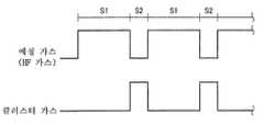
It is a figure which shows the sequence at the time of performing the etching process which supplies HF gas, and the purge process which supplies a gas cluster alternately.
이하, 도면을 참조하여, 본 발명의 실시예에 대해서 설명한다.Hereinafter, embodiments of the present invention will be described with reference to the drawings.
도 1은 본 발명의 일 실시형태에 따른 에칭 장치를 탑재한 처리 시스템을 나타내는 개략 구성도이다. 이 처리 시스템(1)은, 반도체 웨이퍼 (이하, 단순히 웨이퍼로 기술한다)(W)를 반출입하는 반출입부(2)와, 반출입부(2)에 인접하여 마련된 2개의 로드록실(L/L)(3)과, 각 로드록실(3)에 각각 인접해서 마련된, 웨이퍼(W)에 대하여 PHT(Post Heat Treatment) 처리를 행하는 PHT 처리 장치(PHT)(4)와, 각 PHT 처리 장치(4)에 각각 인접해서 마련된, 웨이퍼(W)에 대하여 비플라즈마 에칭인 COR 처리를 행하는 COR 처리 장치(5)를 구비하고 있다. COR 처리 장치(5)는, 본 실시형태에 관한 에칭 장치로서 기능하고, 웨이퍼(W)의 표면에 형성된 SiN막을 HF 가스에 의해 에칭하는 것이다. 로드록실(3), PHT 처리 장치(4) 및 COR 처리 장치(5)는, 이 순서대로 일직선 상에 배열되어 마련되어 있다.BRIEF DESCRIPTION OF THE DRAWINGS It is a schematic block diagram which shows the processing system equipped with the etching apparatus which concerns on one Embodiment of this invention. This processing system 1 includes a carry-out / out
반출입부(2)는, 웨이퍼(W)를 반송하는 제 1 웨이퍼 반송 기구(11)가 내부에 마련된 반송실(L/M)(12)을 가지고 있다. 제 1 웨이퍼 반송 기구(11)는, 웨이퍼(W)를 대략 수평으로 유지하는 2개의 반송 아암(11a, 11b)을 가지고 있다. 반송실(12)의 길이 방향의 측부에는, 탑재대(13)가 마련되어 있고, 이 탑재대(13)에는, 웨이퍼(W)를 복수매 나열하여 수용 가능한 캐리어(C)가, 예를 들면, 3개 접속할 수 있도록 되어 있다. 또한, 반송실(12)에 인접하여, 웨이퍼(W)를 회전시켜서 편심량을 광학적으로 구하여 위치 정렬을 행하는 오리엔터(14)가 설치되어 있다.The carrying in / out
반출입부(2)에 있어서, 웨이퍼(W)는, 반송 아암(11a, 11b)에 의해 유지되고, 제 1 웨이퍼 반송 기구(11)의 구동에 의해 대략 수평면 내에서 직진 이동, 또한 승강되는 것에 의해, 소망하는 위치에 반송된다. 그리고, 탑재대(13)상의 캐리어(C), 오리엔터(14), 로드록실(3)에 대하여 각각 반송 아암(11a, 11b)이 진퇴하는 것에 의해, 반출입되도록 되어 있다.In the carrying-in / out
각 로드록실(3)은, 반송실(12)과의 사이에 각각 게이트 밸브(16)가 개재된 상태에서, 반송실(12)에 각각 연결되어 있다. 각 로드록실(3)내에는, 웨이퍼(W)를 반송하는 제 2 웨이퍼 반송 기구(17)가 마련되어 있다. 또한, 로드록실(3)은, 소정의 진공도까지 진공 배기 가능하게 구성되어 있다.Each
제 2 웨이퍼 반송 기구(17)는, 다관절 아암 구조를 가지고 있고, 웨이퍼(W)를 대략 수평으로 유지하는 피크를 가지고 있다. 이 웨이퍼 반송 기구(17)에 있어서는, 다관절 아암을 수축한 상태에서 피크가 로드록실(3)내에 위치하고, 다관절 아암을 신장하는 것에 의해, 피크가 PHT 처리 장치(4)에 도달하고, 또한 신장하는 것에 의해 COR 처리 장치(5)에 도달하는 것이 가능하게 되어 있고, 웨이퍼(W)를 로드록실(3), PHT 처리 장치(4), 및 COR 처리 장치(5) 사이에서의 웨이퍼(W)를 반송하는 것이 가능하게 되어 있다.The second
PHT 처리 장치(4)는, 도 2에 도시하는 바와 같이, 진공 배기 가능한 챔버(20)와, 그 중에서 웨이퍼(W)를 탑재하는 탑재대(23)를 가지고, 탑재대(23)에는 히터(24)가 매설되어 있고, 이 히터(24)에 의해 COR 처리가 실시된 후의 웨이퍼(W)를 가열해서 COR 처리에 의해 생성한 반응 생성물을 기화(승화)시키는 PHT 처리를 행한다. 챔버(20)의 로드록실(3)측에는, 로드록실(3)과의 사이에서 웨이퍼를 반송하는 반입출구(20a)가 마련되어 있고, 이 반입출구(20a)는 게이트 밸브(22)에 의해 개폐 가능하게 되어 있다. 또한, 챔버(20)의 COR 처리 장치(5)측에는 COR 처리 장치(5)와의 사이에서 웨이퍼(W)를 반송하는 반입출구(20b)가 마련되어 있고, 이 반입출구(20b)는 게이트 밸브(54)에 의해 개폐 가능하게 되어 있다. 또한, 챔버(20)에, 예를 들면, 질소 가스(N2) 등의 불활성 가스를 공급하는 가스 공급로(25)를 구비한 가스 공급 기구(26), 및 챔버(20)내를 배기하는 배기로(27)를 구비한 배기 기구(28)가 구비되어 있다. 가스 공급로(25)는, 질소 가스 공급원(30)에 접속되어 있다. 그리고, 가스 공급로(25)에는, 유로의 개폐 동작 및 질소 가스의 공급 유량의 조절이 가능한 유량 조정 밸브(31)가 개설되어 있다. 배기 기구(28)의 배기로(27)에는, 개폐 밸브(32) 및 진공 펌프(33)가 마련되어 있다.As shown in FIG. 2, the
COR 처리 장치(5)는, 도 3에 도시하는 바와 같이, 밀폐 구조의 챔버(40)를 구비하고 있고, 챔버(40)의 내부에는, 웨이퍼(W)를 대략 수평으로 한 상태로 탑재시키는 탑재대(42)가 마련되어 있다. 또한, COR 처리 장치(5)에는, 챔버(40)에 HF 가스 및 NH3 가스 등을 공급하는 가스 공급 기구(43), 챔버(40)내를 배기하는 배기 기구(44)가 마련되어 있다.The
챔버(40)는, 챔버 본체(51)와 커버부(52)와에 의해 구성되어 있다. 챔버 본체(51)는, 거의 원통 형상의 측벽부(51a)와 바닥부(51b)와를 가지고, 상부는 개구로 되어 있고, 이 개구가 커버부(52)로 닫힌다. 측벽부(51a)와 커버부(52)와는, 시일 부재(도시하지 않음)에 의해 시일되고, 챔버(40)내의 기밀성이 확보된다.The
측벽부(51a)에는, PHT 처리 장치(4)의 챔버(20)에 대하여 웨이퍼(W)를 반출입하는 반입출구(53)가 마련되어 있고, 이 반입출구(53)는 게이트 밸브(54)에 의해 개폐 가능하게 되어 있다.The
탑재대(42)는, 평면시에 있어서 대략 원형을 이루고 있고, 챔버(40)의 바닥부(51b)에 고정되어 있다. 탑재대(42)의 내부에는, 탑재대(42)의 온도를 조절하는 온도 조절기(65)가 마련되어 있다. 온도 조절기(65)는, 예를 들면, 온도 조절용 매체(예를 들면, 물 등)가 순환하는 관로(管路)를 구비하고 있고, 이러한 관로내를 흐르는 온도 조절용 매체와 탑재대(42) 간에 열교환이 행해지도록 하는 것에 의해, 탑재대(42)의 온도가 조절되고, 탑재대(42)상의 웨이퍼(W)의 온도 제어가 이루어진다.The mounting table 42 is substantially circular in plan view, and is fixed to the bottom 51b of the
챔버(40)의 커버부(52)는, 외측을 구성하는 커버 부재(55)와, 커버 부재(55)의 내측에 감입되어, 탑재대(42)를 향하도록 마련된 샤워헤드(56)를 가지고 있다. 샤워헤드(56)는 원통 형상을 이루는 측벽(57a)과 상부벽(57b)을 가지는 본체(57)와, 본체(57)의 바닥부에 마련된 샤워 플레이트(58)를 가지고 있다. 본체(57)와 샤워 플레이트(58)로 형성되는 공간에는, 샤워 플레이트(58)와 평행하게 플레이트(59)가 마련되어 있고, 본체(57)의 상부벽(57b)과 플레이트(59)와의 사이는 제 1 공간(60a)으로 되어 있고, 플레이트(59)와 샤워 플레이트(58)와의 사이는 제 2 공간(60b)으로 되어 있다.The
제 1 공간(60a)에는, 가스 공급 기구(43)의 제 1 가스 공급 배관(71)이 삽입되어 있고, 제 1 공간(60a)에 연결되는 복수의 가스 통로(61)가 플레이트(59)로부터 샤워 플레이트(58)에 연장되고 있다. 이 가스 통로(61)는, 샤워 플레이트(58)에 형성된 복수의 제 1 가스 토출 구멍(62)에 연결되어 있다. 한편, 제 2 공간(60b)에는, 가스 공급 기구(43)의 제 2 가스 공급 배관(72)이 삽입되어 있고, 이 제 2 공간(60b)에는, 샤워 플레이트(58)에 형성된 복수의 제 2 가스 토출 구멍(63)이 연결되어 있다.The first
그리고, 제 1 가스 공급 배관(71)으로부터 제 1 공간(60a)에 공급된 가스가 가스 통로(61) 및 제 1 가스 토출 구멍(62)을 거쳐서 챔버(40)내에 토출된다. 또한, 제 2 가스 공급 배관(72)으로부터 제 2 공간(60b)에 공급된 가스가 제 2 가스 토출 구멍(63)을 거쳐서 챔버(40)내에 토출된다.The gas supplied from the first
가스 공급 기구(43)는, 상술한 제 1 가스 공급 배관(71) 및 제 2 가스 공급 배관(72)을 가지고 있고, 또한 이들 제 1 가스 공급 배관(71) 및 제 2 가스 공급 배관(72)에 각각 접속된 HF 가스 공급원(73) 및 클러스터 가스 공급원(74)을 가지고 있다. 또한, 제 1 가스 공급 배관(71)에는 제 3 가스 공급 배관(75)이 접속되어 있고, 제 3 가스 공급 배관(75)에는, 희석 가스로서의 Ar 가스를 공급하는 Ar 가스 공급원(77)이 접속되어 있다. 희석 가스로서는 Ar 가스에 한하지 않으며, N2 가스 등의 다른 불활성 가스라도 좋다. 제 1 ~ 제 3 가스 공급 배관(71, 72, 75)에는 유로의 개폐 동작 및 유량 제어를 행하는 유량 제어기(79)가 마련되어 있다. 유량 제어기(79)는, 예를 들면, 개폐 밸브 및 매스 플로우 컨트롤러에 의해 구성되어 있다.The
HF 가스 및 희석 가스로서의 Ar 가스는, 제 1 가스 공급 배관(71), 제 1 공간(60a) 및 가스 통로(61)를 거쳐서 제 1 가스 토출 구멍(62)으로부터 챔버(40)내에 토출되고, 클러스터 가스는, 제 2 가스 공급 배관(72) 및 제 2 공간(60b)을 거쳐서 제 2 가스 토출 구멍(63)으로부터 챔버(40)내에 분사된다.Ar gas as the HF gas and the dilution gas is discharged into the
도 4의 저면도에 도시하는 바와 같이, HF 가스 등을 토출하는 제 1 가스 토출 구멍(62) 및 클러스터 가스를 토출하는 제 2 가스 토출 구멍(63)은, 다수가 교대로 형성되어 있다.As shown in the bottom view of FIG. 4, the 1st
제 2 가스 토출 구멍(63)으로부터 분사된 클러스터 가스는, 배기 기구(44)에 의해 진공 배기된 챔버(40)내에서 단열 팽창하고, 가스의 원자 또는 분자의 일부가 반데르발스힘에 의해 수개에서 수만개가 응집하여 가스 클러스터가 된다. 가스 클러스터를 형성하기 위한 클러스터 가스는 특별히 한정되지 않지만, Ar 가스, N2 가스, CO2 가스 등의 불활성 가스가 예시된다. 또한, 제 2 가스 토출 구멍(63)의 직경은, 클러스터화에 적합한 길이, 예를 들면, 0.2 ~ 3.0 mm정도로 하는 것이 바람직하다.The cluster gas injected from the second
반응 가스인 HF 가스는 SiN막을 에칭할 때에, 반응 생성물로서 NH3 가스와 고체 형상의 불소 화합물을 생성시킨다. 가스 클러스터는, 반응 생성물인 NH3 가스를 챔버(40)의 외부에 효율적으로 배출하는 기능을 가진다.HF gas, which is a reaction gas, generates NH3 gas and a solid fluorine compound as reaction products when etching the SiN film. The gas cluster has a function of efficiently discharging NH3 gas, which is a reaction product, to the outside of the
배기 기구(44)는, 챔버(40)의 바닥부(51b)에 형성된 배기구(81)에 연결되는 배기 배관(82)을 가지고 있고, 또한, 배기 배관(82)에 마련된, 챔버(40)내의 압력을 제어하기 위한 자동 압력 제어 밸브(APC)(83) 및 챔버(40)내를 배기하기 위한 진공 펌프(84)를 가지고 있다.The
챔버(40)의 측벽으로부터 챔버(40)내에, 챔버(40)내의 압력을 계측하기 위한 2개의 캐패시턴스 마노미터(86a, 86b)가 마련되어 있다. 캐패시턴스 마노미터(86a)는 고압력용, 캐패시턴스 마노미터(86b)는 저압력용으로 되어 있다. 탑재대(42)에 탑재된 웨이퍼(W)의 근방에는, 웨이퍼(W)의 온도를 검출하는 온도 센서(도시하지 않음)가 마련되어 있다.In the
COR 처리 장치(5)를 구성하는 챔버(40), 탑재대(42) 등의 각종 구성 부품의 재질로서는, Al이 이용되고 있다. 챔버(40)를 구성하는 Al재는 순수한 것이라도 좋고, 내면(챔버 본체(51)의 내면, 샤워헤드(56)의 하면 등)에 양극 산화 처리를 실시한 것이라도 좋다. 한편, 탑재대(42)를 구성하는 Al의 표면은 내마모성이 요구되므로, 양극 산화 처리를 행하여 표면에 내마모성이 높은 산화 피막(Al2O3)을 형성하는 것이 바람직하다.Al is used as a material of various component parts, such as the
도 1에 도시하는 바와 같이, 처리 시스템(1)은 제어부(90)를 가지고 있다. 제어부(90)는, 처리 시스템(1)의 각 구성부를 제어하는 마이크로 프로세서(컴퓨터)를 구비한 프로세스 컨트롤러(91)를 가지고 있다. 프로세스 컨트롤러(91)에는, 오퍼레이터가 처리 시스템(1)을 관리하기 위해서 커맨드의 입력 조작 등을 행하는 키보드나, 처리 시스템(1)의 가동 상황을 가시화해서 표시하는 디스플레이 등을 가지는 유저 인터페이스(92)가 접속되어 있다. 또한, 프로세스 컨트롤러(91)에는, 처리 시스템(1)으로 실행되는 각종 처리, 예를 들면, COR 처리 장치(5)에 있어서의 처리 가스의 공급이나 챔버(40)내의 배기 등을 프로세스 컨트롤러(91)의 제어로 실현하기 위한 제어 프로그램이나, 처리 조건에 따라 처리 시스템(1)의 각 구성부에 소정의 처리를 실행시키기 위한 처리 레시피나, 각종 데이타베이스 등이 저장된 기억부(93)가 접속되어 있다. 레시피는 기억부(93) 안의 적당한 기억 매체(도시하지 않음)에 기억되어 있다. 그리고, 필요에 따라서, 임의의 레시피를 기억부(93)로부터 호출해서 프로세스 컨트롤러(91)에서 실행시키는 것에 의해, 프로세스 컨트롤러(91)의 제어 하에서, 처리 시스템(1)에서의 소망하는 처리가 행해진다.As shown in FIG. 1, the processing system 1 has a control unit 90. The control part 90 has the
다음에, 이러한 처리 시스템(1)을 이용한 본 실시형태의 에칭 방법에 대해서 설명한다.Next, the etching method of this embodiment using this processing system 1 is demonstrated.
본 실시형태에서는, 웨이퍼(W) 상에 존재하는 SiN막을 에칭한다. 예를 들면, 도 5에 도시하는 바와 같이, 실리콘 기판(200) 상에 SiN막(201) 및 패턴화된 SiO2막(202)이 형성되어 있는 웨이퍼(W)에 있어서, SiN막(201)을 에칭한다.In this embodiment, the SiN film which exists on the wafer W is etched. For example, as shown in FIG. 5, in the wafer W in which the
먼저, 도 5에 나타내는 상태의 웨이퍼(W)를 캐리어(C)내에 수납하고, 처리 시스템(1)에 반송한다. 처리 시스템(1)에 있어서는, 대기측의 게이트 밸브(16)를 연 상태에서 반출입부(2)의 캐리어(C)로부터 제 1 웨이퍼 반송 기구(11)의 반송 아암(11a, 11b) 중 어느 하나에 의해 웨이퍼(W)를 1매 로드록실(3)에 반송하고, 로드록실(3)내의 제 2 웨이퍼 반송 기구(17)의 피크에 전달한다.First, the wafer W of the state shown in FIG. 5 is accommodated in the carrier C, and is conveyed to the processing system 1. In the processing system 1, any one of the conveying
그 후, 대기측의 게이트 밸브(16)를 닫아서 로드록실(3)내를 진공 배기하고, 다음에 게이트 밸브(22) 및 게이트 밸브(54)를 열어서, 피크를 COR 처리 장치(5)까지 신장하여 탑재대(42)에 웨이퍼(W)를 탑재한다.Thereafter, the
그 후, 피크를 로드록실(3)에 되돌리고, 게이트 밸브(54)를 닫고, 챔버(40)내를 밀폐 상태로 한다. 이 상태에서, 온도 조절기(65)에 의해 탑재대(42) 상의 웨이퍼(W)의 온도를 소정의 온도(예를 들면, 10~200℃)로 조절하고, 가스 공급 기구(43)로부터, HF 가스 및 Ar 가스를, 제 1 가스 공급 배관(71), 제 1 공간(60a) 및 가스 통로(61)를 거쳐서 제 1 가스 토출 구멍(62)으로부터 챔버(40)내에 토출한다.Thereafter, the peak is returned to the
이에 따라, HF 가스는 챔버(40)내에 공급되고, 챔버(40)내의 분위기는 HF 가스를 포함하는 분위기가 되고, 웨이퍼(W) 상에 형성된 SiN막(201)이 선택적으로 HF 가스와 반응한다.Accordingly, the HF gas is supplied into the
이 때, SiO2는 HF와는 반응하기 어렵기 때문에, SiO2막(202)은 거의 에칭되지 않을 것이다. 그러나, HF 가스에 의해 SiN막(201)을 에칭했을 때에 반응 생성물로서 NH3 가스가 발생하고, 그 촉매 효과에 의해 SiO2막(202)의 에칭이 진행되어 버린다. 이 때문에, 이와 같이 SiN막과 SiO2막이 공존한 상태에서 SiN막을 SiO2막에 대하여 고에칭 선택비로 에칭하는 것은 매우 곤란하다.At this time, since SiO2 hardly reacts with HF, the SiO2 film 202 will hardly be etched. However, when the
이러한 문제를 해소하기 위해서는, 적당한 타이밍으로 챔버(40)내를 진공 배기 및 퍼지 가스의 공급에 의해 NH3 가스를 퍼지하는 것이 생각되지만, 이러한 챔버(40)내의 퍼지는 시간이 걸리고, 양산성이 나빠져버린다.In order to solve this problem, it is conceivable to purge the NH3 gas in the
여기서, 본 실시형태에서는, Ar 가스나 CO2 가스 등의 클러스터 가스를 샤워헤드(56)의 제 2 가스 토출 구멍(63)으로부터 진공으로 유지된 챔버(40)에 분사시킴으로써, 단열 팽창시켜서, 클러스터 가스의 원자 또는 분자의 일부가 반데르발스힘에 의해 수개로부터 수만개가 응집한 가스 클러스터를 형성시키고, 가스 클러스터에 의해 챔버(40)내에서 생성한 반응 생성물인 NH3 가스를 챔버(40) 외부에 배출시킨다. 가스 클러스터는 물리적 작용이 크기 때문에, 챔버(40)내에서 생성한 반응 생성물인 NH3 가스를 신속하게 배출시킬 수 있고, NH3 가스를 퍼지하는 시간을 통상의 가스 퍼지보다도 극히 짧게 할 수 있다. 이 때문에, 양산성을 해치는 일 없이 에칭 반응에 의해 생성된 NH3 가스를 챔버(40)로부터 제거할 수 있다.Here, in the present embodiment, by injecting the cluster gas such as Ar gas and CO2 gas in the
이에 따라, HF 가스에 의해 SiO2막이 거의 에칭되는 일 없이 SiN막을 에칭할 수 있고, 높은 에칭 선택비로 SiN막을 에칭할 수 있다.As a result, the SiN film can be etched with almost no etching of the SiO2 film by HF gas, and the SiN film can be etched with a high etching selectivity.
실제의 에칭에 있어서는, 도 6에 도시하는 바와 같이, HF 가스를 공급하는 에칭 공정(S1)과, 클러스터 가스를 공급하는 것에 의해 생성되는 가스 클러스터에 의한 퍼지 공정(S2)을 교대로 반복하는 것에 의해 행할 수 있다. 이 때, 가스 클러스터에 의한 퍼지 공정(S2)은 겨우 수초 정도로 할 수 있다. 또한, 에칭 공정(S1)은, 10 ~ 30sec 정도로 할 수 있다. 또한, 에칭 가스인 HF 가스와 가스 클러스터를 동시에 공급하고, 반응 생성물인 NH3 가스를 배출하면서 에칭을 행하도록 할 수도 있다.In actual etching, as shown in FIG. 6, the etching process S1 which supplies HF gas, and the purge process S2 by the gas cluster produced by supplying a cluster gas are alternately repeated. This can be done by. At this time, the purge process (S2) by the gas cluster can be made into only a few seconds. In addition, etching process S1 can be made into about 10-30 sec. Further, the etching may be performed while simultaneously supplying the HF gas and the gas cluster, which are etching gases, and the NH3 gas, which is a reaction product.
이러한 에칭이 종료한 후, 웨이퍼(W)의 표면에는 고체 형상의 반응 생성물로서 불소 화합물이 잔존하고 있으므로, PHT 처리 장치(4)에 의해 불소 화합물의 가열 제거를 행한다.After completion of such etching, since the fluorine compound remains as a solid reaction product on the surface of the wafer W, the fluorine compound is heated and removed by the
구체적으로는, 게이트 밸브(22, 54)를 열고, 제 2 웨이퍼 반송 기구(17)의 피크에 의해 탑재대(42) 상의 처리후의 웨이퍼(W)를 수취하고, PHT 처리 장치(4)의 챔버(20)내의 탑재대(23) 상에 탑재한다. 그리고, 피크를 로드록실(3)에 퇴피시키고, 게이트 밸브(22, 54)를 닫고, 챔버(20)내에 N2 가스를 도입하면서, 히터(24)에 의해 탑재대(23)상의 웨이퍼(W)를 가열한다. 이에 따라, 상기 COR 처리에 의해 발생한 불소 화합물이 가열되어서 기화하여 제거된다.Specifically, the
이렇게, COR 처리 후, PHT 처리를 행하는 것에 의해, 드라이 분위기에서 반응 생성물인 불소 화합물을 제거할 수 있고, 워터마크 등이 발생하지 않는다. 또한, 플라즈마 없이 에칭할 수 있으므로 손상이 적은 처리가 가능해진다. 또한, COR 처리는, 소정 시간 경과 후, 에칭이 진행되지 않으므로, 오버 에칭을 시도해도 반응이 진행하지 않고, 엔드 포인트 관리가 불필요하게 된다.Thus, by performing PHT processing after COR processing, the fluorine compound which is a reaction product can be removed in dry atmosphere, and a watermark etc. do not generate | occur | produce. In addition, since etching can be performed without plasma, a process with little damage can be performed. In addition, since a COR process does not advance etching after predetermined time passes, even if it tries to overetch, reaction does not progress and end point management becomes unnecessary.
이상, 본 실시형태에 의하면, COR 처리 장치(5)에 있어서, HF 가스에 의해 SiN막의 에칭을 행할 때의 반응에 의해 생성되는 NH3 가스를 가스 클러스터에 의해 챔버(40)의 외부에 배출시키므로, 극히 단시간에 NH3을 챔버(40)로부터 제거할 수 있다. 또한, 이와 같이 NH3 가스를 챔버(40)로부터 제거하는 것에 의해, HF 가스와 NH3 가스와의 공존에 의해 발생하는 SiO2막의 에칭을 억제할 수 있고, SiO2막에 대하여 고에칭 선택비로 SiN막을 에칭할 수 있다.As described above, according to the present embodiment, since the NH3 gas generated by the reaction when the SiN film is etched by the HF gas is discharged to the outside of the
또, 본 발명은 상기 실시 형태에 한정되는 일 없이, 여러가지 변형이 가능하다. 예를 들면, 상기 실시 형태에서는, SiN막을 HF 가스로 에칭하는 경우에 대해서 나타냈지만, 에칭 대상막 및 에칭 가스는 이에 한하지 않고, 적층막 중 소정의 막을 소정의 에칭 가스로 에칭할 때에, 다른 막의 에칭을 진행시키는 가스가 생성되는 경우, 예를 들면, HF로 Si를 에칭하여 SiF4이 발생되는 경우 등, 에칭시의 반응에 의해 제거해야 할 가스가 발생하는 경우의 전반에 유효하다.In addition, this invention is not limited to the said embodiment, A various deformation | transformation is possible. For example, in the said embodiment, although the case where the SiN film was etched with HF gas was shown, the etching target film and the etching gas are not limited to this, and when etching a predetermined film among laminated films with a predetermined etching gas, It is effective in the first half of the case where a gas to be etched is generated, for example, when Si is etched with HF to generate SiF4 , and a gas to be removed by the reaction during etching is generated.
또한, 상기 실시 형태에서는, 클러스터 가스로서 Ar 가스, N2 가스, CO2 가스 등의 불활성 가스를 예시했지만, 본 발명의 클러스터 가스는 에칭시의 반응에 의해 생성된 가스를 배출하기 위한 것으로, 에칭에 악영향을 미치지 않고 이러한 기능을 발휘할 수 있다면, 불활성 가스에 한하지 않는다.In the above embodiment, although an example of an inert gas such as Ar gas, N2 gas, CO2 gas is used as the cluster gas, cluster gas of the present invention is designed to discharge the gas generated by the reaction at the time of etching, the etching If it can exert such a function without adversely affecting, it is not limited to inert gas.
또한, 상기 실시 형태에서는, 피처리 기판으로서 반도체 웨이퍼를 이용한 경우에 대해서 나타냈지만, 반도체 웨이퍼에 한하지 않고, LCD(액정 디스플레이)용 기판으로 대표되는 FPD(플랫 패널 디스플레이) 기판이나, 세라믹 기판 등의 다른 기판이라도 좋다.
In addition, in the said embodiment, although the case where a semiconductor wafer was used as a to-be-processed substrate was shown, it is not limited to a semiconductor wafer, FPD (flat panel display) board | substrate represented by the substrate for LCD (liquid crystal display), a ceramic substrate, etc. Other substrates may be used.
1: 처리 시스템 2: 반출입부
3: 로드록실 4: PHT 처리 장치
5: COR 처리 장치 11: 제 1 웨이퍼 반송 기구
17: 제 2 웨이퍼 반송 기구 40: 챔버
43: 가스 공급 기구 44: 배기 기구
56: 샤워헤드 73: HF 가스 공급원
74: 클러스터 가스 공급원 77: 아르곤 가스 공급원
86a, 86b: 캐패시턴스 마노미터 90: 제어부
200: 실리콘 기판 201: SiN막
202: SiO2막 W: 반도체 웨이퍼1: Processing system 2:
3: loadlock room 4: PHT processing unit
5: COR processing apparatus 11: 1st wafer conveyance mechanism
17: second wafer transfer mechanism 40: chamber
43: gas supply mechanism 44: exhaust mechanism
56: showerhead 73: HF gas source
74: cluster gas source 77: argon gas source
86a, 86b: Capacitance manometer 90:
200: silicon substrate 201: SiN film
202: SiO2 film W: semiconductor wafer
Claims (15)
Translated fromKorean상기 챔버 내를 배기하는 배기 기구와,
상기 챔버 내에 에칭 가스를 도입하는 에칭 가스 도입 기구와,
상기 챔버 내에 가스 클러스터를 생성하기 위한 클러스터 가스를 분사해서 상기 챔버 내에 가스 클러스터를 생성하는 가스 클러스터 생성 기구를 구비하고,
상기 에칭 가스에 의한 상기 에칭 대상막의 에칭시에, 반응에 의해 생성되는 가스를, 상기 가스 클러스터 생성 기구에서 분사된 클러스터 가스로부터 생성된 가스 클러스터에 의해 상기 챔버로부터 배출시키는 것을 특징으로 하는 에칭 장치.
A chamber in which a substrate to be processed having an etching target film is accommodated;
An exhaust mechanism for exhausting the inside of the chamber,
An etching gas introduction mechanism for introducing an etching gas into the chamber;
A gas cluster generating mechanism for injecting a cluster gas for generating a gas cluster in the chamber to generate a gas cluster in the chamber,
In the etching of the etching target film by the etching gas, the gas generated by the reaction is discharged from the chamber by a gas cluster generated from the cluster gas injected by the gas cluster generating mechanism.
상기 에칭 가스 도입 기구 및 상기 가스 클러스터 생성 기구는, 상기 에칭 가스를 상기 챔버에 토출하고, 또한 상기 클러스터 가스를 상기 챔버에 분사하는 공통의 샤워헤드를 가지는 것을 특징으로 하는 에칭 장치.
The method of claim 1,
The etching gas introduction mechanism and the gas cluster generating mechanism have a common shower head which discharges the etching gas into the chamber and injects the cluster gas into the chamber.
상기 에칭 대상막은 SiN막이며, 상기 에칭 가스는 HF 가스이며, 상기 반응에 의해 생성되는 가스는 NH3 가스인 것을 특징으로 하는 에칭 장치.
3. The method according to claim 1 or 2,
The etching target film is an SiN film, the etching gas is an HF gas, and the gas generated by the reaction is an NH3 gas.
상기 피처리 기판은, 표면에 적층막을 가지고, 상기 적층막 중 소정의 막이 상기 에칭 대상막이며, 상기 반응에 의해 생성되는 가스는, 상기 적층막의 다른 막의 에칭의 진행에 기여하는 것을 특징으로 하는 에칭 장치.
3. The method according to claim 1 or 2,
The said to-be-processed substrate has a laminated film on the surface, the predetermined | prescribed film | membrane of the said laminated film is the said etching target film, and the gas produced | generated by the said reaction contributes to the progress of the etching of the other film | membrane of the said laminated film. Device.
상기 에칭 대상막은 SiN막이며, 상기 다른 막은 SiO2막이며, 상기 에칭 가스는 HF 가스이며, 상기 반응에 의해 생성되는 가스는 NH3 가스인 것을 특징으로 하는 에칭 장치.
5. The method of claim 4,
The etching target film is a SiN film, the other film is a SiO2 film, the etching gas is an HF gas, and the gas generated by the reaction is an NH3 gas.
상기 가스 클러스터 생성 기구는, 상기 클러스터 가스로서 불활성 가스를 이용하는 것을 특징으로 하는 에칭 장치.
6. The method according to any one of claims 1 to 5,
The gas cluster generating mechanism uses an inert gas as the cluster gas.
상기 챔버 내에 에칭 가스를 도입하여 상기 에칭 대상막을 에칭하고,
상기 에칭 대상막의 에칭시에, 반응에 의해 생성되는 가스를, 상기 챔버 내에 클러스터 가스를 분사하는 것에 의해 생성된 가스 클러스터를 사용함으로써 상기 챔버로부터 배출시키는 것을 특징으로 하는 에칭 방법.
A substrate to be treated having an etching target film is accommodated in the chamber,
An etching gas is introduced into the chamber to etch the etching target film;
At the time of etching of the said etching target film, the gas produced | generated by reaction is discharged | emitted from the said chamber by using the gas cluster produced | generated by injecting a cluster gas into the said chamber.
상기 에칭 대상막은 SiN막이며, 상기 에칭 가스는 HF 가스이며, 상기 반응에 의해 생성되는 가스는 NH3가스인 것을 특징으로 하는 에칭 방법.
The method of claim 7, wherein
The etching target film is a SiN film, the etching gas is an HF gas, and the gas generated by the reaction is NH3. It is a gas, The etching method characterized by the above-mentioned.
상기 피처리 기판은, 표면에 적층막을 가지고, 상기 적층막 중 소정의 막이 상기 에칭 대상막이며, 상기 반응에 의해 생성되는 가스는, 상기 적층막의 다른 막의 에칭의 진행에 기여하는 것을 특징으로 하는 에칭 방법.
The method of claim 7, wherein
The said to-be-processed substrate has a laminated film on the surface, the predetermined | prescribed film | membrane of the said laminated film is the said etching target film, and the gas produced | generated by the said reaction contributes to the progress of the etching of the other film | membrane of the said laminated film. Way.
상기 에칭 대상막은 SiN막이며, 상기 다른 막은 SiO2막이며, 상기 에칭 가스는 HF 가스이며, 상기 반응에 의해 생성되는 가스는 NH3 가스인 것을 특징으로 하는 에칭 방법.
The method of claim 9,
The etching target film is an SiN film, the other film is a SiO2 film, the etching gas is an HF gas, and the gas generated by the reaction is an NH3 gas.
상기 클러스터 가스로서 불활성 가스를 이용하는 것을 특징으로 하는 에칭 방법.
11. The method according to any one of claims 7 to 10,
An inert gas is used as the cluster gas.
상기 클러스터 가스는, Ar 가스 또는 CO2 가스인 것을 특징으로 하는 에칭 방법.
The method of claim 11,
The cluster gas is an Ar gas or a CO2 gas.
상기 에칭 대상막의 에칭과, 상기 반응에 의해 생성되는 가스의 배출을 교대로 행하는 것을 특징으로 하는 에칭 방법.
13. The method according to any one of claims 7 to 12,
The etching method of the said etching target film and discharge | emission of the gas produced | generated by the said reaction are performed alternately.
상기 에칭 대상막의 에칭과, 상기 반응에 의해 생성되는 가스의 배출을 동시에 행하는 것을 특징으로 하는 에칭 방법.
13. The method according to any one of claims 7 to 12,
Etching method, characterized in that the etching of the etching target film and the discharge of the gas generated by the reaction at the same time.
Applications Claiming Priority (2)
| Application Number | Priority Date | Filing Date | Title |
|---|---|---|---|
| JPJP-P-2012-203418 | 2012-09-14 | ||
| JP2012203418AJP5997555B2 (en) | 2012-09-14 | 2012-09-14 | Etching apparatus and etching method |
Publications (2)
| Publication Number | Publication Date |
|---|---|
| KR20140035832Atrue KR20140035832A (en) | 2014-03-24 |
| KR101716535B1 KR101716535B1 (en) | 2017-03-14 |
Family
ID=50273393
Family Applications (1)
| Application Number | Title | Priority Date | Filing Date |
|---|---|---|---|
| KR1020130108193AExpired - Fee RelatedKR101716535B1 (en) | 2012-09-14 | 2013-09-10 | Etching apparatus and etching method |
Country Status (3)
| Country | Link |
|---|---|
| US (1) | US9236272B2 (en) |
| JP (1) | JP5997555B2 (en) |
| KR (1) | KR101716535B1 (en) |
Families Citing this family (6)
| Publication number | Priority date | Publication date | Assignee | Title |
|---|---|---|---|---|
| JP6139986B2 (en)* | 2013-05-31 | 2017-05-31 | 東京エレクトロン株式会社 | Etching method |
| KR102468565B1 (en) | 2014-10-06 | 2022-11-17 | 티이엘 매뉴팩처링 앤드 엔지니어링 오브 아메리카, 인크. | Systems and methods for treating substrates with cryogenic fluid mixtures |
| FR3041471B1 (en)* | 2015-09-18 | 2018-07-27 | Commissariat A L'energie Atomique Et Aux Energies Alternatives | METHOD FOR FORMING SPACERS OF A GRID OF A TRANSISTOR |
| JP6813459B2 (en) | 2017-09-08 | 2021-01-13 | キオクシア株式会社 | Plasma processing equipment |
| JP7459720B2 (en)* | 2020-08-11 | 2024-04-02 | 東京エレクトロン株式会社 | Method, apparatus and system for etching silicon oxide film |
| KR20220087623A (en)* | 2020-12-17 | 2022-06-27 | 삼성전자주식회사 | Apparatus for processing a substrate |
Citations (5)
| Publication number | Priority date | Publication date | Assignee | Title |
|---|---|---|---|---|
| JP2005039185A (en) | 2003-06-24 | 2005-02-10 | Tokyo Electron Ltd | Work processing apparatus, work processing method therefor, pressure control method, work carrying method, and carrying apparatus |
| JP2008160000A (en) | 2006-12-26 | 2008-07-10 | Tokyo Electron Ltd | Gas processing apparatus, gas processing method, and storage medium |
| KR20120030000A (en)* | 2010-09-17 | 2012-03-27 | 도쿄엘렉트론가부시키가이샤 | Vacuum processing apparatus, vacuum processing method, and micro-machining apparatus |
| JP2012084656A (en)* | 2010-10-08 | 2012-04-26 | Denso Corp | Semiconductor manufacturing apparatus and semiconductor manufacturing method |
| US8187486B1 (en)* | 2007-12-13 | 2012-05-29 | Novellus Systems, Inc. | Modulating etch selectivity and etch rate of silicon nitride thin films |
Family Cites Families (11)
| Publication number | Priority date | Publication date | Assignee | Title |
|---|---|---|---|---|
| US5505816A (en)* | 1993-12-16 | 1996-04-09 | International Business Machines Corporation | Etching of silicon dioxide selectively to silicon nitride and polysilicon |
| JP2004091829A (en)* | 2002-08-30 | 2004-03-25 | Tokyo Electron Ltd | Etching method and etching apparatus |
| US20050241669A1 (en)* | 2004-04-29 | 2005-11-03 | Tokyo Electron Limited | Method and system of dry cleaning a processing chamber |
| US20070048456A1 (en)* | 2004-09-14 | 2007-03-01 | Keshner Marvin S | Plasma enhanced chemical vapor deposition apparatus and method |
| JP4652282B2 (en)* | 2006-05-30 | 2011-03-16 | 三菱電機株式会社 | Silicon substrate surface treatment method and solar cell manufacturing method |
| JP4954734B2 (en)* | 2007-01-30 | 2012-06-20 | 東京エレクトロン株式会社 | Substrate processing apparatus and gas supply method |
| JP5374039B2 (en)* | 2007-12-27 | 2013-12-25 | 東京エレクトロン株式会社 | Substrate processing method, substrate processing apparatus, and storage medium |
| KR101002493B1 (en)* | 2007-12-28 | 2010-12-17 | 주식회사 하이닉스반도체 | Device Separation Method of Semiconductor Memory Device |
| US8252194B2 (en)* | 2008-05-02 | 2012-08-28 | Micron Technology, Inc. | Methods of removing silicon oxide |
| JP5210191B2 (en)* | 2009-02-03 | 2013-06-12 | 東京エレクトロン株式会社 | Silicon nitride film dry etching method |
| JP5815967B2 (en)* | 2011-03-31 | 2015-11-17 | 東京エレクトロン株式会社 | Substrate cleaning apparatus and vacuum processing system |
- 2012
- 2012-09-14JPJP2012203418Apatent/JP5997555B2/ennot_activeExpired - Fee Related
- 2013
- 2013-09-10KRKR1020130108193Apatent/KR101716535B1/ennot_activeExpired - Fee Related
- 2013-09-10USUS14/022,449patent/US9236272B2/ennot_activeExpired - Fee Related
Patent Citations (5)
| Publication number | Priority date | Publication date | Assignee | Title |
|---|---|---|---|---|
| JP2005039185A (en) | 2003-06-24 | 2005-02-10 | Tokyo Electron Ltd | Work processing apparatus, work processing method therefor, pressure control method, work carrying method, and carrying apparatus |
| JP2008160000A (en) | 2006-12-26 | 2008-07-10 | Tokyo Electron Ltd | Gas processing apparatus, gas processing method, and storage medium |
| US8187486B1 (en)* | 2007-12-13 | 2012-05-29 | Novellus Systems, Inc. | Modulating etch selectivity and etch rate of silicon nitride thin films |
| KR20120030000A (en)* | 2010-09-17 | 2012-03-27 | 도쿄엘렉트론가부시키가이샤 | Vacuum processing apparatus, vacuum processing method, and micro-machining apparatus |
| JP2012084656A (en)* | 2010-10-08 | 2012-04-26 | Denso Corp | Semiconductor manufacturing apparatus and semiconductor manufacturing method |
Also Published As
| Publication number | Publication date |
|---|---|
| JP2014060221A (en) | 2014-04-03 |
| JP5997555B2 (en) | 2016-09-28 |
| US9236272B2 (en) | 2016-01-12 |
| KR101716535B1 (en) | 2017-03-14 |
| US20140076849A1 (en) | 2014-03-20 |
Similar Documents
| Publication | Publication Date | Title |
|---|---|---|
| TWI682453B (en) | Etching method | |
| JP6139986B2 (en) | Etching method | |
| TWI806835B (en) | Etching method and manufacturing method of DRAM capacitor | |
| JP6110848B2 (en) | Gas processing method | |
| JP6073172B2 (en) | Etching method | |
| TWI669757B (en) | Etching method | |
| JP6097192B2 (en) | Etching method | |
| TWI648790B (en) | Etching method | |
| KR20140035832A (en) | Etching apparatus and etching method | |
| JP2020205304A (en) | Etching method and etching equipment | |
| KR101715460B1 (en) | Gas treatment method | |
| WO2015186461A1 (en) | Method for etching | |
| JP2015073035A (en) | Etching method | |
| JP2014013841A (en) | Processing method and conditioning method |
Legal Events
| Date | Code | Title | Description |
|---|---|---|---|
| PA0109 | Patent application | St.27 status event code:A-0-1-A10-A12-nap-PA0109 | |
| PG1501 | Laying open of application | St.27 status event code:A-1-1-Q10-Q12-nap-PG1501 | |
| A201 | Request for examination | ||
| P11-X000 | Amendment of application requested | St.27 status event code:A-2-2-P10-P11-nap-X000 | |
| P13-X000 | Application amended | St.27 status event code:A-2-2-P10-P13-nap-X000 | |
| PA0201 | Request for examination | St.27 status event code:A-1-2-D10-D11-exm-PA0201 | |
| P22-X000 | Classification modified | St.27 status event code:A-2-2-P10-P22-nap-X000 | |
| D13-X000 | Search requested | St.27 status event code:A-1-2-D10-D13-srh-X000 | |
| D14-X000 | Search report completed | St.27 status event code:A-1-2-D10-D14-srh-X000 | |
| E902 | Notification of reason for refusal | ||
| PE0902 | Notice of grounds for rejection | St.27 status event code:A-1-2-D10-D21-exm-PE0902 | |
| E13-X000 | Pre-grant limitation requested | St.27 status event code:A-2-3-E10-E13-lim-X000 | |
| P11-X000 | Amendment of application requested | St.27 status event code:A-2-2-P10-P11-nap-X000 | |
| P13-X000 | Application amended | St.27 status event code:A-2-2-P10-P13-nap-X000 | |
| E701 | Decision to grant or registration of patent right | ||
| PE0701 | Decision of registration | St.27 status event code:A-1-2-D10-D22-exm-PE0701 | |
| GRNT | Written decision to grant | ||
| PR0701 | Registration of establishment | St.27 status event code:A-2-4-F10-F11-exm-PR0701 | |
| PR1002 | Payment of registration fee | St.27 status event code:A-2-2-U10-U11-oth-PR1002 Fee payment year number:1 | |
| PG1601 | Publication of registration | St.27 status event code:A-4-4-Q10-Q13-nap-PG1601 | |
| FPAY | Annual fee payment | Payment date:20200218 Year of fee payment:4 | |
| PR1001 | Payment of annual fee | St.27 status event code:A-4-4-U10-U11-oth-PR1001 Fee payment year number:4 | |
| PR1001 | Payment of annual fee | St.27 status event code:A-4-4-U10-U11-oth-PR1001 Fee payment year number:5 | |
| PR1001 | Payment of annual fee | St.27 status event code:A-4-4-U10-U11-oth-PR1001 Fee payment year number:6 | |
| PC1903 | Unpaid annual fee | St.27 status event code:A-4-4-U10-U13-oth-PC1903 Not in force date:20230309 Payment event data comment text:Termination Category : DEFAULT_OF_REGISTRATION_FEE | |
| P22-X000 | Classification modified | St.27 status event code:A-4-4-P10-P22-nap-X000 | |
| PC1903 | Unpaid annual fee | St.27 status event code:N-4-6-H10-H13-oth-PC1903 Ip right cessation event data comment text:Termination Category : DEFAULT_OF_REGISTRATION_FEE Not in force date:20230309 |