KR20140032363A - Fluoroscopy systems and methods - Google Patents
Fluoroscopy systems and methodsDownload PDFInfo
- Publication number
- KR20140032363A KR20140032363AKR1020137017677AKR20137017677AKR20140032363AKR 20140032363 AKR20140032363 AKR 20140032363AKR 1020137017677 AKR1020137017677 AKR 1020137017677AKR 20137017677 AKR20137017677 AKR 20137017677AKR 20140032363 AKR20140032363 AKR 20140032363A
- Authority
- KR
- South Korea
- Prior art keywords
- imaging system
- control
- range
- fluoroscopy
- step size
- Prior art date
- Legal status (The legal status is an assumption and is not a legal conclusion. Google has not performed a legal analysis and makes no representation as to the accuracy of the status listed.)
- Granted
Links
Images


Classifications
- A—HUMAN NECESSITIES
- A61—MEDICAL OR VETERINARY SCIENCE; HYGIENE
- A61B—DIAGNOSIS; SURGERY; IDENTIFICATION
- A61B6/00—Apparatus or devices for radiation diagnosis; Apparatus or devices for radiation diagnosis combined with radiation therapy equipment
- A61B6/46—Arrangements for interfacing with the operator or the patient
- A61B6/461—Displaying means of special interest
- A—HUMAN NECESSITIES
- A61—MEDICAL OR VETERINARY SCIENCE; HYGIENE
- A61B—DIAGNOSIS; SURGERY; IDENTIFICATION
- A61B6/00—Apparatus or devices for radiation diagnosis; Apparatus or devices for radiation diagnosis combined with radiation therapy equipment
- A61B6/12—Arrangements for detecting or locating foreign bodies
- A—HUMAN NECESSITIES
- A61—MEDICAL OR VETERINARY SCIENCE; HYGIENE
- A61B—DIAGNOSIS; SURGERY; IDENTIFICATION
- A61B6/00—Apparatus or devices for radiation diagnosis; Apparatus or devices for radiation diagnosis combined with radiation therapy equipment
- A61B6/46—Arrangements for interfacing with the operator or the patient
- A61B6/467—Arrangements for interfacing with the operator or the patient characterised by special input means
- A—HUMAN NECESSITIES
- A61—MEDICAL OR VETERINARY SCIENCE; HYGIENE
- A61B—DIAGNOSIS; SURGERY; IDENTIFICATION
- A61B6/00—Apparatus or devices for radiation diagnosis; Apparatus or devices for radiation diagnosis combined with radiation therapy equipment
- A61B6/48—Diagnostic techniques
- A61B6/486—Diagnostic techniques involving generating temporal series of image data
- A61B6/487—Diagnostic techniques involving generating temporal series of image data involving fluoroscopy
- A—HUMAN NECESSITIES
- A61—MEDICAL OR VETERINARY SCIENCE; HYGIENE
- A61B—DIAGNOSIS; SURGERY; IDENTIFICATION
- A61B6/00—Apparatus or devices for radiation diagnosis; Apparatus or devices for radiation diagnosis combined with radiation therapy equipment
- A61B6/54—Control of apparatus or devices for radiation diagnosis
Landscapes
- Health & Medical Sciences (AREA)
- Life Sciences & Earth Sciences (AREA)
- Engineering & Computer Science (AREA)
- Medical Informatics (AREA)
- Radiology & Medical Imaging (AREA)
- Molecular Biology (AREA)
- Biophysics (AREA)
- Nuclear Medicine, Radiotherapy & Molecular Imaging (AREA)
- Optics & Photonics (AREA)
- Pathology (AREA)
- Physics & Mathematics (AREA)
- Biomedical Technology (AREA)
- Heart & Thoracic Surgery (AREA)
- High Energy & Nuclear Physics (AREA)
- Surgery (AREA)
- Animal Behavior & Ethology (AREA)
- General Health & Medical Sciences (AREA)
- Public Health (AREA)
- Veterinary Medicine (AREA)
- Human Computer Interaction (AREA)
- Apparatus For Radiation Diagnosis (AREA)
Abstract
Translated fromKorean
Description
Translated fromKorean본원에 개시된 청구 대상은 X선 이미징 시스템에 관한 것으로서, 특히 형광투시 이미징 시스템 및 방법에 관한 것이다.The subject matter disclosed herein relates to X-ray imaging systems, and more particularly to fluoroscopic imaging systems and methods.
형광투시 이미징 시스템은 이미징 동작 중에 비디오로서 보여질 수 있는 환자의 해부학적 조직(또는 움직이거나 또는 움직이지 않는(inanimate) 피검자의 내부 피처(feature))의 X선 이미지를 획득하는 것을 돕는다. 그러한 형광투시 시스템은, 혈관 조영술(angiographic) 시술, 위장 내의(gastrointestinal) 시술, 심장(cardiology) 시술 등과 같은, 매우 다양한 의료적인 시술 중에 환자의 해부학적 조직을 관찰하기 위한 여러 가지 적용예에서 이용된다. 임상적인(clinical) 적용예에 따라서, 전형적으로 방사선 기사(radiologist)가 이미징 시스템의 셋업과 관련되는 복수의 시스템 매개변수에 영향을 미치는 동작 모드를 선택한다. 예를 들면, 선택된 모드는 환자에게 노출되는 X선 선량(dose), 디스플레이 상에서 얻어지는 이미지 품질 등에 영향을 미칠 수도 있다.The fluoroscopic imaging system helps to acquire an X-ray image of the patient's anatomical tissue (or internal features of a moving or inanimate subject) that can be viewed as a video during an imaging operation. Such fluoroscopy systems are used in various applications for observing a patient's anatomical tissue during a wide variety of medical procedures, such as angiographic procedures, gastrointestinal procedures, cardiology procedures, and the like. . Depending on the clinical application, a radiologist typically selects an operating mode that affects a plurality of system parameters related to the setup of the imaging system. For example, the selected mode may affect the X-ray dose exposed to the patient, the image quality obtained on the display, and the like.
그러한 형광투시 이미징 시스템이 채용될 수 있는 여러 가지 시술이 다양하기 때문에, 고정된 값으로 시스템에 의해서 미리 세팅된 이미징 매개변수는 실시되는 이미징 동작에 대해서 최적이 되지 못할 수 있다. 추가적으로, 이미징 동작의 일부에 대해서 적합한 이미징 매개변수 값이 동일한 동작의 다른 부분에 대해서는 적합하지 않을 수 있다. 일부 전통적인 시스템은, 시스템의 제어 패널 상에 배치된 제어부의 각각에 대해서 주어진 고정된 범위 및 스텝(step) 크기를 제공함으로써, 이미징 동작 중에 조작자가 조정할 수 있게 허용한다. 그러나, 모든 조작자 및 시술에 대해서 동일하게 유지되는 미리 세팅된 범위 및 스텝 크기는, 이미징 동작 중에 이미징 매개변수를 제어할 수 있는 조작자의 능력을 여전히 제한한다. 따라서, 그러한 단점을 극복하는 개선된 형광투시 시스템에 대한 필요성이 존재하고 있다.Because of the variety of procedures in which such fluoroscopic imaging systems can be employed, imaging parameters preset by the system to fixed values may not be optimal for the imaging operation being performed. In addition, suitable imaging parameter values for some of the imaging operations may not be suitable for other portions of the same operation. Some traditional systems allow the operator to adjust during an imaging operation by providing a fixed range and step size given for each of the controls disposed on the control panel of the system. However, the preset range and step size, which remain the same for all operators and procedures, still limits the operator's ability to control imaging parameters during the imaging operation. Thus, there is a need for an improved fluoroscopy system that overcomes such disadvantages.
일 실시예에 따르면, 형광투시 이미징 시스템은 피검자의 제 1 측부(side)에 배치되고, X선을 발생시켜 X선을 피검자를 향해서 투사하도록 구성된 X선 발생기를 포함한다. 이미징 시스템은 또한 피검자의 제 1 측부에 반대되는 피검자의 제 2 측부 상에 배치되고, 피검자에 의해서 감쇠된(attenuated) 후의 X선 발생기로부터의 X선을 수신하고 감쇠된 X선을 피검자 피처를 나타내는 디지털 신호로 변환하는 검출기를 포함한다. 또한, 이미징 시스템은 검출기에 커플링되며, 또한 검출기로부터 디지털 신호를 수신하고, 디지털 신호를 프로세스하고, 프로세스된 디지털 신호를 디스플레이용 모니터로 통신하도록 구성된 제어 회로를 포함한다. 추가적으로, 이미징 시스템은 디지털 신호에 영향을 미치는 하나 이상의 이미징 매개변수를 사용자가 조정할 수 있게 하도록 구성된 적어도 하나의 설정가능한 조정부를 포함하는 사용자 인터페이스를 포함하며, 상기 제어 회로는 사용자 인터페이스를 통한 사용자로부터의 입력에 기초하여 설정가능한 조정부의 범위, 설정가능한 조정부의 스텝 크기, 또는 설정가능한 조정부의 디폴트값 중 적어도 하나를 세팅하도록 구성된다.According to one embodiment, the fluoroscopic imaging system includes an X-ray generator disposed on a first side of a subject and configured to generate X-rays to project X-rays toward the subject. The imaging system is also disposed on the second side of the subject opposite the first side of the subject and receives X-rays from the X-ray generator after being attenuated by the subject and indicative of the subject feature. And a detector that converts the digital signal. The imaging system also includes control circuitry coupled to the detector and further configured to receive a digital signal from the detector, process the digital signal, and communicate the processed digital signal to a monitor for display. Additionally, the imaging system includes a user interface including at least one configurable adjustment portion configured to enable a user to adjust one or more imaging parameters affecting the digital signal, wherein the control circuitry is provided from the user through the user interface. And configured to set at least one of a range of the settable adjuster, a step size of the settable adjuster, or a default value of the settable adjuster based on the input.
다른 실시예에 따르면, 형광투시 이미징 시스템은 피검자의 제 1 측부 상에 배치되고, X선을 생성하는 X선 공급원, 및 피검자의 제 1 측부에 반대되는 피검자의 제 2 측부 상에 배치되고, 피검자에 의해서 감쇠된 후의 X선을 수신하고 수신된 X선을 피검자 피처를 나타내는 디지털 데이터로 변환하는 X선 검출기를 포함한다. 이미징 시스템은 또한 X선 공급원 및 X선 검출기에 커플링되며, 검출기로부터 디지털 신호를 수신하고, 피검자 피처의 이미지를 생성하기 위해서 디지털 신호를 프로세스하고, 그리고 X선 공급원, X선 검출기, 및/또는 디지털 데이터의 하나 이상의 이미징 매개변수를 제어하는 제어 회로를 포함한다. 이미징 시스템은 X선 공급원, X선 검출기, 또는 디지털 데이터의 하나 이상의 이미징 매개변수 중 적어도 하나의 레벨을 조정할 수 있게 하도록 구성된 적어도 하나의 조정가능한 제어부를 포함하는 사용자 인터페이스를 포함하며, 상기 조정가능한 제어부의 범위는 설정가능하다.According to another embodiment, the fluoroscopic imaging system is disposed on a first side of a subject, disposed on an X-ray source that generates X-rays, and on a second side of the subject opposite to the first side of the subject, And an X-ray detector for receiving the X-rays after being attenuated by and converting the received X-rays into digital data representing the subject features. The imaging system is also coupled to the X-ray source and the X-ray detector, receives the digital signal from the detector, processes the digital signal to generate an image of the subject feature, and the X-ray source, X-ray detector, and / or Control circuitry for controlling one or more imaging parameters of the digital data. The imaging system includes a user interface including at least one adjustable control configured to be able to adjust the level of at least one of an X-ray source, an X-ray detector, or one or more imaging parameters of digital data, the adjustable control The range of can be set.
추가적인 실시예에 따라서, 형광투시 이미징 시스템의 제어 방법은 이미징 동작을 위한 현재 이미징 동작 모드의 선택을 검출하는 단계, 선택된 현재의 이미징 모드에 기초하여 이미징 시스템의 사용자 인터페이스 상에 배치된 적어도 하나의 설정가능한 조정부의 기능을 세팅하는 단계, 그리고 적어도 하나의 설정가능한 조정부의 범위를 사용자가 세팅할 수 있게 하는 단계를 포함한다.According to a further embodiment, a method of controlling a fluoroscopic imaging system includes detecting a selection of a current imaging mode of operation for an imaging operation, at least one setting disposed on a user interface of the imaging system based on the selected current imaging mode. Setting a function of a possible adjustment part, and allowing a user to set a range of at least one settable adjustment part.
본 발명의 이러한 그리고 다른 특징, 양태, 및 장점은 첨부 도면을 참조할 때 이하의 구체적인 설명으로부터 보다 잘 이해될 수 있을 것이고, 상기 도면 전체를 통해서 유사한 참조부호는 유사한 부분을 나타낸다.These and other features, aspects, and advantages of the present invention will be better understood from the following detailed description when taken in conjunction with the accompanying drawings, in which like reference characters designate similar parts throughout.
도 1은 이미징 동작을 통한 환자의 해부학적 조직을 연속적으로 이미징하도록 구성된 예시적인 형광투시 시스템을 도시한 도면,
도 2는 동작될 수 있는 형광투시 시스템의 예시적인 구성요소를 도시한 블록도,
도 3은 형광투시 시스템을 동작시키기 위해서 도 2의 제어 회로에 의해서 채용될 수 있는 예시적인 방법을 도시한 도면,
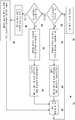
도 4는 사용자 선택 모드에 기초하여 설정가능한 조정부의 기능을 세팅하기 위해서 제어부에 의해서 이용될 수 있는 예시적인 방법을 도시한 블록도,
도 5는 하나 이상의 예시적인 설정가능한 조정부를 포함하는 제어 패널의 실시예를 도시하는 도면.1 illustrates an exemplary fluoroscopy system configured to continuously image a patient's anatomical tissue via an imaging operation;
2 is a block diagram illustrating exemplary components of a fluoroscopic system that can be operated;
3 depicts an exemplary method that may be employed by the control circuit of FIG. 2 to operate a fluoroscopy system;
4 is a block diagram illustrating an exemplary method that may be used by a control unit to set a function of a configurable adjustment unit based on a user selection mode;
5 illustrates an embodiment of a control panel including one or more exemplary configurable adjustments.
이하에서 구체적으로 설명하는 바와 같이, 높은 순간적인(temporal) 해상도로 이미징 시술 중에 환자의 해부학적 조직과 같은 관심 피검자의 내부 피처를 관찰하기 위한 형광투시 이미징 시스템 및 방법이 제공된다. 특정 실시예는 조작자가 설정가능한 조정부를 통해서 형광투시 동작 중에 하나 이상의 이미징 매개변수를 조정할 수 있게 하는 피처를 포함할 수 있으며, 그러한 설정가능한 조정부는 형광투시 시스템의 제어 패널 상에 위치될 수 있다. 설정가능한 조정부의 범위, 설정가능한 조정부의 스텝 크기, 또는 설정가능한 조정부의 디폴트값 중 하나 이상이 이미징 시스템의 제어부에 의해서 자동적으로 세팅될 수 있다. 또한, 본 발명의 실시예는 또한 조작자가 설정가능한 조정부의 범위, 설정가능한 조정부의 스텝 크기, 또는 설정가능한 조정부의 디폴트값 중 적어도 하나를 세팅할 수 있게 할 수 있다. 예를 들어, 일 실시예에서, 제어부는 설정가능한 조정부의 스텝 크기를 약 10%까지 그리고 설정가능한 조정부의 범위를 0% 내지 100% 까지 자동적으로 세팅할 수도 있다. 즉, 범위, 스텝 크기, 및 디폴트값이 조작자의 입력이 없이 미리 규정되고 고정된 전통적인 시스템에 대비할 때, 본 발명의 실시예는 동작이 실시되는 동안에 주어진 동작에 대해서 적절한 적합한 값을 자동적으로 결정할 수 있는 한편, 동작이 수행되는 동안 주어진 동작에 대해서 적절하게 그러한 값을 변경할 수 있는 능력을 조작자에게 제공할 수 있다. 예를 들어, 일부 전통적인 적용예에서, 방사선 기사가, 상이한 범위, 스텝 크기, 및/또는 디폴트값이 요구될 수 있는 상이한 시술 사이에서 전환(transition)할 수도 있다. 그러한 적용예에서, 형광투시 동작 중에 그러한 매개변수를 자동적으로 변경하는 것 및/또는 형광투시 동작 중에 방사선 기사가 그러한 매개변수를 동적으로(dynamically) 변경할 수 있게 하는 것은, 조작자에게 증가된 탄력성(flexibility)을 제공할 수도 있으며, 그에 따라 조작자가 획득 이미지를 보다 최적화할 수 있게 한다.As will be described in detail below, fluoroscopic imaging systems and methods are provided for observing an internal feature of a subject of interest, such as the anatomical tissue of a patient, during an imaging procedure at high temporal resolution. Certain embodiments may include features that enable an operator to adjust one or more imaging parameters during fluoroscopy operations through configurable adjustments, which may be located on the control panel of the fluoroscopy system. One or more of the range of the settable adjustment section, the step size of the settable adjustment section, or the default value of the settable adjustment section may be automatically set by the control section of the imaging system. In addition, embodiments of the present invention may also enable the operator to set at least one of a range of adjustable settings, a step size of adjustable settings, or a default value of adjustable settings. For example, in one embodiment, the controller may automatically set the step size of the configurable adjuster up to about 10% and the range of the configurable adjuster from 0% to 100%. That is, when a range, step size, and default value are prepared for a traditional system that is predefined and fixed without operator input, embodiments of the present invention can automatically determine appropriate suitable values for a given operation while the operation is being performed. On the other hand, it can provide the operator with the ability to change such values as appropriate for a given operation while the operation is being performed. For example, in some traditional applications, the radiographer may transition between different procedures where different ranges, step sizes, and / or default values may be required. In such applications, automatically changing such parameters during fluoroscopic operation and / or allowing the radiographer to dynamically change such parameters during fluoroscopic operation may result in increased flexibility for the operator. ), Which allows the operator to further optimize the acquired image.
본원에 개시된 실시예는 일반적인 형광투시 이미징 시스템의 내용으로 설명되며, 여기에서 환자는 이미징 시술 중에 X선으로 이미지화되어 조작자에게 디스플레이되는 이미징 시퀀스의 실질적으로 연속적인 플로우(예를 들어, 초당 30 프레임)를 생성한다. 그러나, 본 발명의 실시예는, 바륨 삼킴(barium swallow) 검사를 위한 기록형(recorded) 형광투시 시스템, 위치결정(positioning) 시술(예를 들어, 혈관 조영술 시술 중에 카테터의 진행)을 위한 미기록형 형광투시 시스템, 조합된 기록형 및 미기록형 형광투시 시스템(예를 들어, 진단을 위한 미기록형 형광투시를 이용한 위장 형광투시 및 문서화(ducumentation)를 위한 기록형 형광투시) 등과 같은 임의의 적합한 형광투시 시스템에서 이용될 수 있다. 사실상, 설정가능한 조정부 및 설정가능한 조정부를 제어하는 방법의 실시예가 임의의 적합한 방사선 사진 또는 형광투시 시스템에서 적용될 수 있으며, 미기록형 형광투시로 제한되지 않을 것이다.The embodiments disclosed herein are described in the context of a general fluoroscopic imaging system, where the patient is a substantially continuous flow of imaging sequence (eg, 30 frames per second) that is imaged by an X-ray during the imaging procedure and displayed to the operator. Create However, embodiments of the present invention provide a recordable fluoroscopy system for barium swallow testing, an unrecorded type for positioning (e.g., progression of the catheter during angiography). Any suitable fluoroscopy, such as a fluoroscopy system, combined recordable and unrecorded fluoroscopy systems (e.g., gastrointestinal fluoroscopy using unrecorded fluoroscopy for diagnosis and recordable fluoroscopy for documentation), and the like. It can be used in the system. Indeed, embodiments of the settable adjustments and methods of controlling the settable adjustments may be applied in any suitable radiographic or fluoroscopy system, and will not be limited to unrecorded fluoroscopy.
이제 도면을 참조하면, 도 1은, 이미징 동작을 통해서, 의료적인 또는 스크리닝 콘텍스트(screening context)에서 인간 피검자 또는 환자(12)의 해부학적 조직과 같은, 피검자의 내부적인 피처를 연속적으로 이미지화하도록 구성된 예시적인 형광투시 시스템(10)을 도시한다. 도시된 형광투시 시스템(10)은 콜리메이터(16), 포트(17) 및 필터(미도시)를 가지는 X선 튜브(14), 환자가 위치되는 테이블(18), 이미징 콘솔(console)(20), 이미지 증강장치(intensifier)(22), 카메라(24), 및 모니터(26)를 포함한다. 이미징 콘솔(20)은 제 1 제어 패널(30) 및 제 2 제어 패널(32)을 포함하는 사용자 인터페이스(28)를 포함한다. 제 1 제어 패널(30)은 디스플레이(34) 및 복수의 설정가능한 조정부(36)를 포함한다. 제 2 제어 패널(32)은 디스플레이(38) 및 설정가능한 조정부(40 및 42)를 포함하고, 상기 설정가능한 조정부 각각은 매개변수 값을 증가 또는 감소시키도록 구성된다. 모니터(26)는 또한 이미징 동작 중에 이미지의 시퀀스를 조작자에게 디스플레이하도록 구성된 디스플레이(44)를 포함한다.Referring now to the drawings, FIG. 1 is configured to continuously image an internal feature of a subject, such as an anatomical tissue of a human subject or
동작 중에, X선 공급원(14)은, 예를 들어, 통상적인 음극 및 양극 X선 생성 시스템을 통해서 X선 비임을 생성한다. 일부 실시예에서, 콜리메이터(16)에 도달하기 전에 X선 비임을 필터링하여 희망하는 에너지 스펙트럼을 제공할 수도 있다. 이러한 목적을 위해서, 일부 실시예는, 에너지 기반의 필터(예를 들어, 알루미늄), 균등화(equalization) 필터(예를 들어, 트로프(trough) 필터, 바우-타이(bow-tie) 필터, ?지(wedge) 필터 등) 등과 같은 하나 이상의 희망하는 필터를 포함할 수도 있다. 또한, X선 비임의 크기 및 형상은, 포트(17)로부터 빠져나가기에 앞서서, 콜리메이터(16)에 의해서 조정된다. 포트(17)로부터 빠져나간 후에, X선 비임은 테이블(18) 및 상기 테이블 상에 위치된 환자(12)를 통과한다.In operation,
X선 비임은 환자의 해부학적 조직에 의해서 감쇠되고, 감쇠된 비임의 적어도 일부가 이미징 콘솔(20)에 장착된 이미지 증강장치(22)의 고민감성 검출기에 의해서 검출된다. 이미지 증강장치(22)는 적은 수의 X선 광자로부터 수용가능한 품질의 투사 이미지를 생성하도록 구성된다. 그러한 피처는 형광투시 시스템에서 유리할 수 있는데, 이는 이미징 동작을 통한 연속적인 이미징이 환자를 상당한 양의 X선 에너지에 대해서 노출시킬 수 있기 때문이다. 이미지 증강장치(22)로부터의 출력 신호가 비디오 카메라(24)를 통해서 모니터(26)로 연속적으로 전달되어, 이미징 동작 중에 디스플레이(44) 상에서 관찰할 수 있게 한다.The X-ray beam is attenuated by the anatomical tissue of the patient, and at least a portion of the attenuated beam is detected by the high sensitivity detector of the
본원의 개시 내용이 의료용 진단 콘텍스트에서의 형광투시 시스템을 이용하는 것에 대해서 언급하고 있지만, 그러한 시스템은 다른 콘텍스트에서도 또한 이용될 수 있다는 것을 주지하여야 한다. 예를 들어, 인간 피검자에서, 시스템이 스크리닝 및 그와 유사한 적용예를 위해서 이용될 수도 있다. 다른 환경에서, 시스템이 소화물, 수화물, 운반 차량 등 내의 물품을 검출하기 위해서 이용될 수도 있다. 또한, 일부 실시예에서, 그러한 형광투시 이미징 시스템이 파이프 또는 풍력 블레이드와 같은 산업적인 부품의 검사를 위해서 이용될 수도 있다.Although the disclosure herein refers to using a fluoroscopic system in a medical diagnostic context, it should be noted that such a system may also be used in other contexts. For example, in human subjects, the system may be used for screening and similar applications. In other circumstances, the system may be used to detect articles in packages, baggage, transport vehicles, and the like. In addition, in some embodiments, such fluoroscopic imaging systems may be used for inspection of industrial components such as pipes or wind blades.
사용 중에, 형광투시 이미징 동작이 이루어짐에 따라, 조작자는 이미징 동작의 하나 이상의 매개변수를 동적으로 조정하기 위해서 설정가능한 조정부(36, 40 및 42) 중 하나 이상을 이용할 수 있다. 또한, 시스템 제어부는 자동적으로 조정할 수 있고 및/또는 조작자가 형광투시 동작을 통해서 설정가능한 조정부의 각각의 범위, 스텝 크기 및 디폴트값 중 하나 이상을 조정할 수 있다. 예를 들어, 일 실시예에서, 설정가능한 조정부(36)는, 조작자가 노이즈 감소 레벨, 디스플레이되는 비디오에서의 콘트라스트 레벨, 디스플레이되는 비디오의 휘도, 디스플레이되는 이미지의 에지(edge) 증강 등을 제어할 수 있게 허용하도록 구성될 수 있다. 추가적인 예로서, 콘트라스트 레벨을 조정할 수 있도록 조작자에게 제공된 하나의 설정가능한 조정부는 제어부에 의해서 자동적으로 구성될 수 있고 및/또는 해당 설정가능한 조정부과 연관된 범위, 스텝 크기 및 디폴트값을 결정하기 위해서 조작자에 의해서 구성될 수도 있다. 따라서, 필요에 따라서 이미징 시술 중에, 콘트라스트 레벨 조정의 범위, 스텝 크기 및 디폴트값을 시스템이 자동적으로 변경할 수 있고 및/또는 조작자가 변경할 수도 있다. 그러한 피처(특징)는, 그러한 값이 시스템 셋업 중에 미리 결정되고 그리고 이미징 동작을 통해서 고정적으로 유지되는 시스템에 대비하여, 분명한 장점을 제공할 수 있다. 예를 들어, 조정부의 자동적인 및/또는 수동적인 설정가능성을 허용함으로써, 본 발명의 실시예는 이미징 동작 중에 모니터(26) 상에서 디스플레이되는 비디오의 다이나믹한 조정 및 최적화를 촉진할 수 있다.In use, as the fluoroscopic imaging operation is made, the operator may use one or more of the
또한, 일부 실시예에서, 설정가능한 조정부(36, 40 및 42)의 기능은 이미징 동작에 앞서서 및/또는 이미징 동작 중에 결정될 수 있다. 또한, 그러한 조정부의 기능은 동적으로 조정될 수 있고, 그에 따라 동작 중에 자동적으로 및/또는 조작자로부터의 입력에 따라서 변화되도록 구성될 수 있다. 예를 들어, 도시된 실시예에서, 사용자는 이미징 동작의 제 1 부분 동안 이미지 콘트라스트를 증가 및/또는 감소시키기 위해서 조정부(40 및 42)를 이용할 수 있고 및/또는 이미징 동작의 제 2 부분 동안 이미지 휘도를 증가 및/또는 감소시키기 위해서 조정부(40 및 42)를 이용할 수도 있다. 따라서, 설정가능한 조정부(40 및 42)가 이미징 동작 중의 임의의 주어진 시간에 조정하도록 구성된 매개변수를 디스플레이하도록, 디스플레이(38)가 맞춰질 수 있다.Further, in some embodiments, the functionality of the
도시된 설정가능한 조정부는 노브(36) 및 버튼(40 및 42)을 포함한다. 그러나, 다른 실시예에서, 설정가능한 조정부가 노브, 버튼, 스위치, 패널 등을 포함할 수 있으나, 이러한 것으로 제한되지 않는다는 것을 이해하여야 할 것이다. 사실상, 설정가능한 조정부는, 기능, 스텝 크기, 범위 및 디폴트값 중 적어도 하나가 이미징 동작에 앞서서 또는 그 도중에 조작자에 의해서 세팅될 수 있는 형광투시 시스템의 임의 부분에 대해서 커플링되는 임의의 적합한 디바이스일 수 있다. 또한, 일부 실시예에서, 설정가능한 조정부는 디스플레이(예를 들어, 34 또는 38)와 연관되지 않을 수 있을 것이고 그리고 콘솔(20)의 제어 패널 상에 위치되지 않을 수도 있다.The settable adjuster shown includes knob 36 and
도 1의 형광투시 시스템은, 예를 들어 약 0.5 내지 약 5 mA 사이의, X선 비임을 연속적으로 생성하도록 구성된 연속적인 형광투시 시스템으로서 이용하기 위한 것으로 설명되었다는 것을 주지하여야 할 것이다. 그러한 시스템에서, 비디오 카메라(24)는 임의의 적절한 레이트(rate)(예를 들어, 약 30 프레임/초)로 생성된 투사 이미지를 디스플레이하도록 구성될 수도 있다. 그러나, 형광투시 시스템은, 고 선량 레이트 형광투시 시스템(예를 들어, 특별하게 활성화된 형광투시), 펄스형 형광투시(예를 들어, 가변 프레임 레이트 펄스형 형광투시) 등과 같은 임의의 희망하는 타입의 형광투시 시스템일 수 있다는 것을 주지하여야 할 것이다. 사실상, 도 1의 형광투시 시스템의 설정가능한 조정부가 임의의 적합한 형광투시 이미징 시스템에서 이용될 수도 있다.It should be noted that the fluoroscopy system of FIG. 1 has been described for use as a continuous fluoroscopy system configured to continuously produce an X-ray beam, for example between about 0.5 to about 5 mA. In such a system,
도 2는 본 발명의 실시예에 따라서 동작될 수 있는 형광투시 시스템(46)의 예시적인 구성요소를 도시한 블록도이다. 도시된 형광투시 시스템(46)은 X선 튜브(14), X선(48), 환자(12), 이미지 증강장치(22), 광학적 회로(50), 콘솔(20), 사용자 인터페이스(28) 및 모니터(26)를 포함한다. 콘솔(20)은 프로세싱 및 제어 회로(52) 그리고 메모리(54)를 포함한다. 동작 중에, X선 튜브(14)는 환자(12)를 향해서 지향된 X선(48)을 생성한다. 환자를 통과한 후에, 감쇠된 X선의 적어도 일부가 이미지 증강장치(22)에 의해서 검출되고, 그러한 이미지 증강장치는 연속적인 또는 반(semi)-연속적인 동작을 위해서 구성된다. 검출 후에, 이미지 신호가 광학적 회로(50) 및 프로세싱 및 제어 회로(52)로 전달된다.2 is a block diagram illustrating exemplary components of a
프로세싱 회로(52)는 유입 신호를 수신하고, 모니터(26) 상에서의 디스플레이를 위해서 및/또는 메모리(54) 내의 저장을 위해서 그러한 신호를 프로세스한다. 예를 들어, 일 실시예에서, 프로세싱 회로(52)가 사용자 인터페이스를 통해서 조작자로부터 수신된 하나 이상의 입력에 따라서 유입 신호를 프로세스할 수도 있다. 추가적인 예로서, 조작자는 사용자 인터페이스(28) 상에서 설정가능한 조정부의 기능, 디폴트값, 범위 및/또는 스텝 크기를 세팅할 수 있고, 그리고 후속하여 희망하는 매개변수(예를 들어, 콘트라스트 또는 휘도 레벨)를 프로세싱 회로(52)로 통신하기 위해서 설정가능한 조정부를 이용할 수도 있다. 따라서, 프로세싱 회로(52)는 설정가능한 조정부의 하나 이상의 희망하는 피처와 관련하여 사용자 인터페이스(28)로부터 입력을 수신하도록 그리고 수신된 입력에 따라서 그 회로에 배치된 조정부를 구성하도록 구성된다. 추가적으로, 프로세싱 회로(52)는, 수신된 이미지 신호를 모니터(26) 상에서 디스플레이하기에 앞서서 그러한 신호를 프로세스하기 위해서, 상기 구성된 조정부로부터 수신된 입력을 이용하도록 추가적으로 구성된다. 또한, 현재의 동작 모드에 따라서, 제어 회로(52)는 하나 이상의 수신된 신호를 메모리(54)에 저장할 수 있다. 예를 들어, 특정 혈관 조영술 시술에서, 환자(12) 내에 카테터를 위치시키는 동안에, 수신된 이미지 신호를 모니터(26) 상에서 디스플레이하도록 프로세싱 회로(52)가 구성될 수도 있다. 그러나, 카테터의 적절한 배치가 이루진 후에, 방사선 사진 콘트라스트 이미지가 관심의 대상이 되는 관(vessel) 또는 신체 공동(cavity) 내로 주입될 때, 펄스형 방사선 사진 이미지를 기록 및 저장하도록 프로세싱 회로(52)가 구성될 수 있다. 그러한 방식에서, 프로세싱 회로(52)는, 주어진 동작에서 요구되는 경우에, 기록형 그리고 미기록형 형광투시 사이에서 변화되도록 이미징 시스템(46)을 동작시킬 수 있다.Processing
도 3은, 본 발명의 실시예에 따라서 형광투시 시스템을 동작시키기 위해서 도 2의 제어 회로에 의해서 채용될 수 있는 예시적인 방법(56)을 도시한다. 그러한 방법(56)은, 예를 들어, 형광투시 시스템이 조작자에 의해서 파워 온(ON) 될 때, 이미징 시스템의 활성화를 검출하는 단계(블록 58)를 포함한다. 시스템 활성화 후에, 제어 회로는 희망하는 시술 및/또는 모드와 관련된 데이터를 수신한다(블록 60). 예를 들면, 조작자는 소아(pediatric) 모드, 성인 모드, 콘트라스트 재료 타입(예를 들어, 바륨, 요오드 등), 이용되는 수술 도구의 타입(예를 들어, 주사기, 금속 기구 등), 이미징 프레임 레이트 등을 특정할 수 있다. 즉, 제어부는 선택된 모드 또는 시술 타입에 따라서 동작하도록 구성될 수 있다.3 shows an
또한, 상기 방법(56)은 이미징 매개변수와 연관된 설정가능한 조정부의 범위를 선택된 시술 및/또는 모드에 대한 디폴트 범위로 세팅하는 단계(블록 62)를 포함할 수 있다. 유사하게, 상기 방법(56)은 이미징 매개변수와 연관된 설정가능한 조정부의 스텝 크기를 선택된 시술 또는 모드에 대한 디폴트 스텝 크기로 세팅하는 단계(블록 64)를 포함한다. 범위 및 스텝 크기에 대한 디폴트 세팅이 조작자 입력에 무관하게 제어부에 의해서 자동적으로 결정될 수 있고 또는 선택된 특별한 모드 또는 시술에 대한 조작자의 지시에 기초하여 제어부에 의해서 선택될 수 있다는 것을 이해하여야 할 것이다. 그러한 방식에서, 설정가능한 조정부에 대한 디폴트 세팅은 자동적으로 변경될 수 있고 및/또는 주어진 적용예에 대해서 요구되는 경우에 조작자 입력에 기초하여 변경될 수도 있다.In addition, the
일단 개시되면, 제어 회로는 설정가능한 조정부 제어의 이미징 매개변수에 관한 디폴트 범위에 대한 희망하는 변화에 대해 조작자를 재촉하도록(블록 66) 그리고 조작자에 의해서 요구되는 범위를 실행하도록(블록 68) 구성된다. 예를 들어, 소아 환자가 이미지화되는 실시예에서, 조작자는 이미징 매개변수에 대한 설정가능한 조정부의 범위를, 성인 환자에 적합한 보다 높은 범위(예를 들어, 0-9 범위)가 아니라, 낮은 범위(예를 들어, 0-2 범위)로 제한할 수도 있다. 그 대신에, 다른 실시예에서, 제어 회로는, 현재의 검사 타입 및 유입되는 이미지 데이터에 기초하여, 설정가능한 조정부 제어의 이미징 매개변수에 대한 적합한 범위를 자동적으로 결정하고 실행하도록 구성될 수도 있다. 그러한 피처는, 시술 타입에만 기초하여 범위를 자동적으로 결정하고 세팅하는 시스템에 대비하여 장점을 제공할 수 있는데, 이는 일부 경우에서, 동일한 시술 타입에 대해서도, 환자의 크기에 기초하여, 다양한 상이한 범위가 요구될 수도 있다.Once initiated, the control circuitry is configured to prompt the operator for a desired change to the default range for the imaging parameters of the configurable adjuster control (block 66) and to execute the range required by the operator (block 68). . For example, in embodiments where a pediatric patient is imaged, the operator may not set the range of configurable adjustments to the imaging parameters to a lower range (not a higher range (eg, 0-9 range) suitable for an adult patient). For example, in the range 0-2). Instead, in another embodiment, the control circuit may be configured to automatically determine and execute a suitable range for the imaging parameters of the configurable adjuster control based on the current inspection type and the incoming image data. Such features may offer advantages over systems that automatically determine and set ranges based solely on the type of procedure, which, in some cases, may have a variety of different ranges, based on the size of the patient, even for the same type of procedure. May be required.
상기 방법(56)은 또한 셋업에서 설정가능한 조정부에 대해서 개시된 디폴트 스텝 크기에 대한 희망하는 변화에 대해 조작자를 재촉하는 단계(블록 70) 및 조작자에 의해서 요구되는 스텝 크기를 실행하는 단계(블록 72)를 포함한다. 예를 들어, 사용자는 이미징 매개변수와 연관된 설정가능한 조정부의 스텝 크기를 특정 범위의 미세 튜닝을 위한 적절한 희망 스텝 크기로 조정할 수도 있다. 그러한 방식에서, 제어부는, 조작자에 의해서 요구되는 바에 따라서, 제 1 이미징 매개변수에 대한 설정가능한 조정부의 범위 및 스텝 크기를 구성할 수 있다. 또한, 동일한 로직(logic)을 이용하여, 부가적인 이미징 매개변수를 제어하도록 구성된 임의의 부가적인 설정가능한 조정부의 범위 및 스텝 크기를 세팅할 수 있고(블록 74), 그리고 이미징 시술이 가능해질 수 있다(블록 76). 비록, 도시된 방법(56)이 형광투시 시스템의 셋업의 콘텍스트에서 설명되었지만, 다른 실시예에서, 희망에 따라서 범위 및 스텝 크기를 조정하기 위해서 그러한 로직이 이미징 동작의 전체를 통해서 이용될 수 있다는 것을 주지하여야 할 것이다.The
도 4는, 본 발명의 실시예에 따라서 사용자가 선택한 모드에 기초하여 설정가능한 조정부의 기능을 세팅하기 위해서 제어부에 의해서 이용될 수 있는 예시적인 방법(78)을 도시한 블록도이다. 구체적으로, 상기 방법(78)은 형광투시 이미징 동작의 개시를 검출하는 단계(블록 80) 및 제 1 모드가 선택되었는지의 여부를 체크하는 단계(블록 82)를 포함한다. 예를 들어, 제어 회로는 소아 모드, 성인 모드, 콘트라스트 재료 모드 등의 선택에 대해서 체크할 수도 있다. 만약 제 1 모드가 선택된다면, 제어부는 제 1 매개변수 세트에 따라서 설정가능한 조정부의 기능을 세팅하도록 구성된다(블록 84). 즉, 제어부는 설정가능한 조정부의 각각에 대한 매개변수를 선택된 모드에 기초한 제어부로 할당할 수도 있다. 예를 들어, 제 1 설정가능한 조정부가 콘트라스트 레벨과 연관될 수 있고, 제 2 설정가능한 조정부가 휘도 레벨과 연관될 수 있으며, 또한 다른 설정가능한 조정부가 다른 레벨 등과 연관될 수도 있다.4 is a block diagram illustrating an
제 1의 선택된 모드에 따라서 설정가능한 조정부의 기능을 세팅한 후에, 제어부는 시스템 제어부로부터 자동적으로 또는 조작자로부터 설정가능한 조정부의 각각에 대한 희망 범위 및 스텝 크기를 수신하도록 추가적으로 구성된다(블록 86). 즉, 이전과 같이, 사용자는 이미징 모드, 환자 크기 등에 기초하여 희망하는 범위 및 스텝 크기를 규정할 수 있다. 이미징 시스템의 후속 동작을 통해서, 제어부는 선택된 이미징 모드를 계속적으로 모니터링할 수 있고(블록 88), 이미징 모드에서의 변화가 발생된다면, 제어부는 설정가능한 조정부의 기능 중 하나 이상을 리셋할 수 있다.After setting the function of the configurable adjustment portion in accordance with the first selected mode, the control portion is further configured to receive the desired range and step size for each of the adjustment portions that can be set automatically from the system control portion or from the operator (block 86). That is, as before, the user can define the desired range and step size based on the imaging mode, patient size, and the like. Through subsequent operations of the imaging system, the control unit can continuously monitor the selected imaging mode (block 88), and if a change in the imaging mode occurs, the control unit can reset one or more of the functions of the configurable adjustment unit.
제 1 이미징 모드가 선택되지 않을 때, 제어부는 제 2 모드가 선택되었는지의 여부를 체크하고(블록 90), 만약 제 2 모드가 선택된 것으로 체크되었다면, 제어부는 제 2 매개변수 세트에 따라서 설정가능한 조정부의 기능을 세팅한다(블록 92). 예를 들어, 제 2 모드가 성인 이미징 모드일 수 있고, 제어부는 그에 따라 조정부의 기능을 세팅할 수도 있다. 이전과 같이, 이어서 제어부는, 적절한 이미징 매개변수를 세팅하도록 구성된 설정가능한 조정부의 각각에 대해서 희망하는 범위 및 스텝 크기를 수신하고(블록 94), 선택된 모드로의 변화에 대해서 이미징 동작을 계속적으로 모니터링한다(블록 88).When the first imaging mode is not selected, the controller checks whether or not the second mode is selected (block 90), and if the second mode is checked as selected, the controller is configured to adjust according to the second set of parameters. Set the function of (block 92). For example, the second mode may be an adult imaging mode, and the controller may set the function of the adjuster accordingly. As before, the control then receives the desired range and step size for each of the configurable adjustments configured to set the appropriate imaging parameters (block 94) and continuously monitors the imaging operation for changes to the selected mode. (Block 88).
만약 제 2 모드가 선택되지 않는다면, 제어부는 주어진 이미징 시스템(블록 96)과 연관된 임의의 추가적인 모드의 선택에 대해서 체크하고, 선택된 모드 및 조작자 입력에 기초하여 설정가능한 조정부의 각각에 대한 기능, 스텝 크기 및 범위를 실행한다(블록 98). 즉, 비록 단지 2개의 모드 체크만이 설명되었지만, 부가적인 실시예에서, 임의의 희망하는 수의 모드 체크 및 기능적인 매개변수 세트가 제어 로직에 포함될 수 있다는 것을 주지하여야 할 것이다. 그러한 방식에서, 본원에서 개시된 제어 회로의 특정 실시예가 선택된 이미징 모드에 기초하여 설정가능한 조정부의 기능을 세팅하도록 구성될 수도 있다.If the second mode is not selected, the control checks for the selection of any additional modes associated with the given imaging system (block 96), and the function, step size for each of the configurable controls based on the selected mode and operator input. And execute the range (block 98). That is, although only two mode checks have been described, it should be noted that in additional embodiments, any desired number of mode checks and functional parameter sets may be included in the control logic. In such a manner, certain embodiments of the control circuit disclosed herein may be configured to set the function of the configurable adjuster based on the selected imaging mode.
도 5는 본 발명의 양태에 따른 하나 이상의 예시적인 설정가능한 조정부를 포함하는 제어 패널(100)의 실시예를 도시한다. 제어 패널(100)은 제 1 설정가능한 조정부 패널(102), 제 2 설정가능한 조정부 패널(104) 및 제 3 설정가능한 조정부 패널(106)을 포함한다. 제 1 패널(102)은, 하나 이상의 증분 마커(increment marker)(112, 114, 116, 118 및 120)를 향해서 지향될 수 있는 표시부(110)를 가지는 노브(108)를 포함한다. 제 2 패널(104)은, 하나 이상의 증분 마커(126, 128, 130, 132, 및 134)를 향해서 지향될 수 있는 제 2 표시부(124)를 가지는 제 2 노브를 포함한다. 또한, 제 3 패널(106)은 디스플레이(136), 증가 버튼(138) 및 감소 버튼(140)을 포함한다.5 illustrates an embodiment of a
동작 중에, 기능이, 예를 들어, 조작자에 의해서 특정된 바에 따라서 직접적으로 또는 조작자 선택 모드에 기초한 제어부에 의한 결정을 통해서 간접적으로, 제 1 노브(108) 및 제 2 노브(122)에 대해서 할당된다. 유사하게, 제 3 패널(106)의 기능이 결정될 수 있고, 그리고 버튼(138 및 140)이 조정하도록 구성된 매개변수가 디스플레이(136) 상에서 보여질 수 있다. 스텝 크기가 또한 노브(108 및 122)의 각각에 대해서 할당될 수 있다. 즉, 노브가 증감 마커 사이에서(예를 들어, 마커(112)와 마커(114) 사이 또는 마커(130)와 마커(132) 사이에서) 회전될 때 증가되거나 감소되는 이미징 매개변수의 양이 조작자에 의해서 세팅될 수 있다. 추가적으로, 범위가 노브(108 및 122)의 각각에 대해서 할당될 수 있다. 즉, 노브가 극단적인 좌측 위치(예를 들어, 마커(112) 또는 마커(126))로부터 극단적인 우측 위치(예를 들어, 마커(120) 또는 마커(134))로 이동될 때 주어진 이미징 매개변수에 대해서 허용된 변화의 양이 조작자에 의해서 또한 세팅될 수 있다.During operation, a function is assigned to the
유사하게, 제 3 패널(106)에 대한 범위 및 스텝 크기가 조작자 유닛에 기초하여 제어부에 의해서 세팅될 수 있다. 예를 들어, 버튼(138 및 140)이 각각의 누름시에 이미징 매개변수를 증가 또는 감소시키게 될 양(즉, 스텝 크기)이 조작자에 의해서 세팅될 수도 있다. 또한, 일단 세팅되면, 패널(102, 104, 및 106) 상에 배치된 설정가능한 조정부의 범위 및 스텝 크기가 이미징 동작을 통해서 조작자에 의해서 재조정될 수 있다는 것을 주지하여야 할 것이다. 또한, 도시된 제어 패널(100) 상에서 보여지는 설정가능한 조정부는 적절한 설정가능한 조정부의 실시예이며, 그리고 본 발명을 그러한 노브 및 버튼으로 제한하는 것을 의미하는 것은 아니다. 디폴트값, 범위, 스텝 크기, 또는 기능 중 적어도 하나와 관련하여 구성될 수 있는 임의의 적합한 조정이 본 발명의 실시예에 따라서 이용될 수도 있다.Similarly, the range and step size for the
이렇게 기술된 설명은, 최적의 모드를 포함하여, 본 발명을 개시하기 위해서, 그리고 임의의 당업자가, 임의의 디바이스 또는 시스템을 제조 및 이용하는 것 그리고 임의의 포함된 방법을 실행하는 것을 포함하여, 본 발명을 실시할 수 있게 하기 위해서 예를 이용한다. 본 발명의 특허받을 수 있는 범위는 청구항에 의해서 규정될 것이고, 그리고 당업자가 안출할 수 있는 다른 예를 포함할 수도 있다. 그러한 다른 예가 청구항의 문헌적인 언어와 상이하지 않은 구성요소를 가진다면, 또는 그러한 다른 예가 청구항의 문헌적인 언어와 비실질적으로(insubstantial) 상이한 균등한 구성요소를 포함한다면, 그러한 다른 예는 청구항의 범위 내에 포함될 것이다.The description set forth above, including the best mode, discloses the present invention, and any one skilled in the art, including manufacturing and using any device or system, and implementing any included method, Examples are used to enable the invention to be practiced. The patentable scope of the invention will be defined by the claims, and may include other examples that occur to those skilled in the art. If such other examples have elements that do not differ from the literary language of the claims, or if such other examples include equivalent components that are insubstantial from the literal language of the claims, such other examples are within the scope of the claims. Will be included within.
Claims (25)
Translated fromKorean피검자의 제 1 측부 상에 배치되고, X선을 발생시켜 X선을 상기 피검자를 향해서 투사하도록 구성된 X선 발생기;
상기 피검자의 제 1 측부에 반대되는 상기 피검자의 제 2 측부 상에 배치되고, 상기 피검자에 의해서 감쇠된 후의 X선 발생기로부터의 X선을 수신하고 감쇠된 X선을 피검자 피처를 나타내는 디지털 신호로 변환하는 검출기;
상기 검출기에 커플링되며, 형광투시 이미징 동작 중에 상기 검출기로부터 디지털 신호를 수신하고, 디지털 신호를 프로세스하고, 프로세스된 디지털 신호를 디스플레이용 모니터로 통신하도록 구성된 제어 회로; 및
형광투시 이미징 동작 중에 디지털 신호에 영향을 미치는 하나 이상의 이미징 매개변수를 사용자가 조정할 수 있게 하도록 구성된 적어도 하나의 설정가능한 조정부를 포함하는 사용자 인터페이스를 포함하며,
상기 제어 회로는 설정가능한 조정부의 범위, 설정가능한 조정부의 스텝 크기, 또는 설정가능한 조정부의 디폴트값 중 적어도 하나를 세팅하도록 구성되는
형광투시 이미징 시스템.In a fluoroscopic imaging system,
An X-ray generator disposed on the first side of the subject and configured to generate X-rays to project X-rays toward the subject;
Disposed on the second side of the subject opposite the first side of the subject, receiving X-rays from the X-ray generator after being attenuated by the subject and converting the attenuated X-rays into a digital signal representing the subject's features A detector;
Control circuitry coupled to the detector and configured to receive a digital signal from the detector during fluoroscopic imaging operation, process the digital signal, and communicate the processed digital signal to a monitor for display; And
A user interface comprising at least one configurable adjustment configured to enable a user to adjust one or more imaging parameters affecting the digital signal during fluoroscopic imaging operation,
The control circuit is configured to set at least one of a range of a settable adjuster, a step size of a settable adjuster, or a default value of a settable adjuster.
Fluoroscopy Imaging System.
상기 제어 회로는 상기 사용자 인터페이스를 통한 상기 사용자로부터의 입력에 기초하여 상기 설정가능한 조정부의 기능을 세팅하도록 추가적으로 구성되는
형광투시 이미징 시스템.The method of claim 1,
The control circuit is further configured to set a function of the settable adjustment unit based on an input from the user through the user interface.
Fluoroscopy Imaging System.
상기 설정가능한 조정부는 노이즈 레벨, 이미지 콘트라스트 레벨, 약물(agent) 증강 레벨 및 휘도 레벨 중 적어도 하나를 조정하도록 추가적으로 구성되는
형광투시 이미징 시스템.The method of claim 1,
The configurable adjustment unit is further configured to adjust at least one of a noise level, an image contrast level, an agent enhancement level, and a luminance level.
Fluoroscopy Imaging System.
상기 제어 회로는 상기 사용자 인터페이스를 통해 선택된 모드를 수신하고 상기 선택된 모드에 기초하여 상기 설정가능한 조정부의 기능을 세팅하도록 추가적으로 구성되는
형광투시 이미징 시스템.The method of claim 1,
The control circuit is further configured to receive a selected mode via the user interface and to set a function of the configurable adjustment unit based on the selected mode.
Fluoroscopy Imaging System.
상기 설정가능한 조정부는 노브, 누름가능한 버튼 및 전자적 인터페이스 중 적어도 하나인
형광투시 이미징 시스템.The method of claim 1,
The configurable adjustment portion is at least one of a knob, a pushable button and an electronic interface.
Fluoroscopy Imaging System.
상기 제어 회로는 상기 설정가능한 조정부의 범위를 세팅하도록 구성되고, 또한 상기 범위의 일부에 대해서 상기 설정가능한 조정부의 스텝 크기를 결정하여 세팅하도록 추가적으로 구성되는
형광투시 이미징 시스템.The method of claim 1,
The control circuit is configured to set a range of the settable adjustment section, and is further configured to determine and set the step size of the settable adjustment section for a portion of the range.
Fluoroscopy Imaging System.
상기 설정가능한 조정부의 타입, 범위, 스텝 크기 또는 디폴트값 중 적어도 하나는 상기 사용자 인터페이스를 통한 사용자로부터의 입력 및 상기 제어 회로의 자동적인 결정 중 적어도 하나에 기초하여 세팅되는
형광투시 이미징 시스템.The method of claim 1,
At least one of the type, range, step size or default value of the configurable adjustment unit is set based on at least one of an input from the user through the user interface and automatic determination of the control circuitry.
Fluoroscopy Imaging System.
상기 제어 회로는, 상기 설정가능한 조정부의 타입, 범위 및 스텝 크기 중 하나 이상이 디폴트값으로부터 변경될 때, 사용자에게 경고하도록 구성되는
형광투시 이미징 시스템.The method of claim 1,
The control circuitry is configured to warn the user when one or more of the type, range and step size of the configurable adjustment portion are changed from a default value.
Fluoroscopy Imaging System.
상기 선택된 모드는 소아 모드, 콘트라스트 약물 모드 및 수술 기구 모드 중 하나 이상인
형광투시 이미징 시스템.5. The method of claim 4,
The selected mode is one or more of pediatric mode, contrast drug mode and surgical instrument mode.
Fluoroscopy Imaging System.
피검자의 제 1 측부 상에 배치되고, X선을 발생하도록 구성되는 X선 공급원;
상기 피검자의 제 1 측부에 반대되는 상기 피검자의 제 2 측부 상에 배치되고, 상기 피검자에 의해서 감쇠된 후의 X선을 수신하고 수신된 X선을 피검자 피처를 나타내는 디지털 데이터로 변환하도록 구성되는 X선 검출기;
상기 X선 공급원 및 X선 검출기에 커플링되며, 상기 X선 검출기로부터 디지털 데이터를 수신하고, 상기 피검자 피처의 이미지를 생성하기 위해서 상기 디지털 데이터를 프로세스하고, 상기 X선 공급원, 상기 X선 검출기, 및/또는 상기 디지털 데이터의 하나 이상의 이미징 매개변수를 제어하도록 구성되는 제어 회로; 및
형광투시 이미징 동작 중에 상기 X선 공급원, 상기 X선 검출기, 또는 상기 디지털 데이터의 하나 이상의 이미징 매개변수 중 적어도 하나의 레벨을 조정할 수 있게 하도록 구성된 적어도 하나의 조정가능한 제어부를 포함하는 사용자 인터페이스를 포함하며,
상기 조정가능한 제어부의 범위는 설정가능한
형광투시 이미징 시스템.In a fluoroscopic imaging system,
An X-ray source disposed on the first side of the subject and configured to generate X-rays;
An X-ray disposed on the second side of the subject opposite the first side of the subject and configured to receive X-rays after being attenuated by the subject and convert the received X-rays into digital data representing the subject's features Detectors;
Coupled to the X-ray source and X-ray detector, receive the digital data from the X-ray detector, process the digital data to generate an image of the subject feature, the X-ray source, the X-ray detector, And / or control circuitry configured to control one or more imaging parameters of the digital data; And
A user interface including at least one adjustable control configured to be able to adjust the level of at least one of the X-ray source, the X-ray detector, or one or more imaging parameters of the digital data during fluoroscopic imaging operation; ,
The range of the adjustable control is settable
Fluoroscopy Imaging System.
상기 하나 이상의 이미징 매개변수는 노이즈 레벨, 이미지 콘트라스트 레벨, 약물 증강 레벨, X선 세기 레벨, 검출기 민감도 레벨 및 휘도 레벨 중 적어도 하나를 포함하는
형광투시 이미징 시스템.11. The method of claim 10,
The one or more imaging parameters include at least one of noise level, image contrast level, drug enhancement level, X-ray intensity level, detector sensitivity level and luminance level.
Fluoroscopy Imaging System.
상기 조정가능한 제어부의 스텝 크기는 조작자에 의해서 세팅되고 사용자 인터페이스를 통해 상기 제어 회로로 통신되도록 구성되는
형광투시 이미징 시스템.11. The method of claim 10,
The step size of the adjustable control is set by an operator and configured to communicate with the control circuit via a user interface.
Fluoroscopy Imaging System.
상기 조정가능한 제어부의 기능은 사용자 인터페이스를 통해 조작자에 의해서 지시된 시술 또는 이미징 모드에 기초하여 상기 제어 회로에 의해서 결정되도록 구성되는
형광투시 이미징 시스템.11. The method of claim 10,
The function of the adjustable control is configured to be determined by the control circuit based on a procedure or imaging mode instructed by an operator via a user interface.
Fluoroscopy Imaging System.
상기 조정가능한 제어부의 범위는 조작자에 의해서 세팅되고 사용자 인터페이스를 통해 상기 제어 회로로 통신되도록 구성되는
형광투시 이미징 시스템.11. The method of claim 10,
The range of the adjustable control is set by an operator and configured to communicate with the control circuit via a user interface.
Fluoroscopy Imaging System.
상기 제어 회로는, 상기 조정가능한 제어부의 범위가 조정됨에 따라 상기 이미징 동작 중에 상기 범위의 미리 세팅된 부분에 대해서 상기 조정가능한 제어부의 스텝 크기를 동적으로 조정하도록 구성되는
형광투시 이미징 시스템.11. The method of claim 10,
The control circuit is configured to dynamically adjust the step size of the adjustable control with respect to a preset portion of the range during the imaging operation as the range of the adjustable control is adjusted.
Fluoroscopy Imaging System.
상기 조정가능한 제어부는 노브, 누름가능 버튼 및 전자적 인터페이스 중 적어도 하나인
형광투시 이미징 시스템.11. The method of claim 10,
The adjustable control is at least one of a knob, a pushable button and an electronic interface.
Fluoroscopy Imaging System.
상기 제어 회로는, 상기 사용자 인터페이스를 통한 사용자로부터의 입력 또는 상기 제어 회로에 의해서 자동적으로 수행되는 결정에 기초하여, 상기 설정가능한 조정부의 타입, 범위 및 스텝 크기 중 하나 이상이 디폴트값으로부터 변경될 때, 사용자에게 경고하도록 구성되는
형광투시 이미징 시스템.11. The method of claim 10,
The control circuitry is adapted to change one or more of the type, range, and step size of the configurable adjustment portion based on an input from a user through the user interface or a decision made automatically by the control circuit. , Configured to warn the user
Fluoroscopy Imaging System.
이미징 동작을 위한 현재 이미징 동작 모드의 선택을 검출하는 단계;
선택된 현재의 이미징 모드에 기초하여 이미징 시스템의 사용자 인터페이스 상에 배치된 적어도 하나의 설정가능한 조정부의 기능을 세팅하는 단계; 및
형광투시 이미징 동작 중에 적어도 하나의 설정가능한 조정부의 범위를 사용자가 세팅할 수 있게 하는 단계를 포함하는
형광투시 이미징 시스템의 제어 방법.In the control method of the fluoroscopic imaging system,
Detecting a selection of a current imaging mode of operation for the imaging operation;
Setting a function of at least one configurable adjustment portion disposed on a user interface of the imaging system based on the selected current imaging mode; And
Allowing a user to set a range of at least one configurable adjustment portion during fluoroscopic imaging operation
Method of Control of a Fluoroscopy Imaging System.
적어도 하나의 설정가능한 조정부의 스텝 크기를 사용자가 세팅할 수 있게 하는 단계를 더 포함하는
형광투시 이미징 시스템의 제어 방법.19. The method of claim 18,
Allowing the user to set a step size of the at least one configurable adjustment portion
Method of Control of a Fluoroscopy Imaging System.
선택된 범위에 기초하여 적어도 하나의 설정가능한 조정부의 스텝 크기를 자동적으로 결정하여 세팅하는 단계를 더 포함하는
형광투시 이미징 시스템의 제어 방법.19. The method of claim 18,
And automatically determining and setting the step size of the at least one configurable adjustment portion based on the selected range.
Method of Control of a Fluoroscopy Imaging System.
이미징 동작 중에 현재의 이미징 동작 모드의 변화를 검출하고, 검출된 현재의 이미징 동작 모드에 기초하여 적어도 하나의 설정가능한 조정부의 기능을 리셋하는 단계를 더 포함하는
형광투시 이미징 시스템의 제어 방법.19. The method of claim 18,
Detecting a change in a current imaging mode of operation during an imaging operation, and resetting a function of the at least one settable adjuster based on the detected current imaging mode of operation;
Method of Control of a Fluoroscopy Imaging System.
상기 적어도 하나의 설정가능한 조정부의 기능이 리셋된 후에 상기 적어도 하나의 설정가능한 조정부의 범위를 사용자가 리셋할 수 있게 하는 단계를 더 포함하는
형광투시 이미징 시스템의 제어 방법.The method of claim 19,
Enabling the user to reset the range of the at least one settable adjuster after the function of the at least one settable adjuster is reset
Method of Control of a fluoroscopic imaging system.
상기 적어도 하나의 설정가능한 조정부의 기능 및 범위가 리셋된 후에 상기 적어도 하나의 설정가능한 조정부의 스텝 크기를 사용자가 리셋할 수 있게 하는 단계를 더 포함하는
형광투시 이미징 시스템의 제어 방법.23. The method of claim 22,
Enabling the user to reset the step size of the at least one settable adjuster after the function and range of the at least one settable adjuster are reset
Method of Control of a Fluoroscopy Imaging System.
이미징 동작 중에 획득된 이미지 데이터에 기초하여 상기 설정가능한 조정부의 적절한 범위 및 적절한 스텝 크기 중 하나 이상을 자동적으로 결정하는 단계를 더 포함하는
형광투시 이미징 시스템의 제어 방법.19. The method of claim 18,
And automatically determining one or more of an appropriate range and an appropriate step size of the configurable adjustment portion based on the image data obtained during the imaging operation.
Method of Control of a Fluoroscopy Imaging System.
상기 사용자로부터의 입력 또는 자동적인 결정에 기초하여, 상기 설정가능한 조정부의 타입, 범위 및 스텝 크기 중 하나 이상이 디폴트값으로부터 변경될 때, 사용자에게 경고하는 단계를 더 포함하는
형광투시 이미징 시스템의 제어 방법.19. The method of claim 18,
Alerting the user when one or more of the type, range, and step size of the configurable adjustment portion are changed from a default value based on an input or automatic determination from the user;
Method of Control of a Fluoroscopy Imaging System.
Applications Claiming Priority (4)
| Application Number | Priority Date | Filing Date | Title |
|---|---|---|---|
| US201113986673A | 2011-01-07 | 2011-01-07 | |
| US12/986,673US8681942B2 (en) | 2011-01-07 | 2011-01-07 | Fluoroscopy systems and methods |
| US12/986,673 | 2011-01-07 | ||
| PCT/US2011/064053WO2012094097A1 (en) | 2011-01-07 | 2011-12-09 | Fluoroscopy systems and methods |
Publications (2)
| Publication Number | Publication Date |
|---|---|
| KR20140032363Atrue KR20140032363A (en) | 2014-03-14 |
| KR101895090B1 KR101895090B1 (en) | 2018-09-04 |
Family
ID=50643971
Family Applications (1)
| Application Number | Title | Priority Date | Filing Date |
|---|---|---|---|
| KR1020137017677AActiveKR101895090B1 (en) | 2011-01-07 | 2011-12-09 | Fluoroscopy systems and methods |
Country Status (1)
| Country | Link |
|---|---|
| KR (1) | KR101895090B1 (en) |
Citations (4)
| Publication number | Priority date | Publication date | Assignee | Title |
|---|---|---|---|---|
| JP2007509687A (en)* | 2003-10-29 | 2007-04-19 | コーニンクレッカ フィリップス エレクトロニクス エヌ ヴィ | Apparatus and method for adjusting imaging parameters of X-ray apparatus |
| JP2008212644A (en)* | 2007-02-06 | 2008-09-18 | Canon Inc | Radiation imaging apparatus, driving method thereof, and radiation imaging system |
| US20080319275A1 (en)* | 2007-06-20 | 2008-12-25 | Surgmatix, Inc. | Surgical data monitoring and display system |
| US20100061507A1 (en)* | 2007-03-01 | 2010-03-11 | Hideki Fujii | X-ray apparatus |
- 2011
- 2011-12-09KRKR1020137017677Apatent/KR101895090B1/enactiveActive
Patent Citations (4)
| Publication number | Priority date | Publication date | Assignee | Title |
|---|---|---|---|---|
| JP2007509687A (en)* | 2003-10-29 | 2007-04-19 | コーニンクレッカ フィリップス エレクトロニクス エヌ ヴィ | Apparatus and method for adjusting imaging parameters of X-ray apparatus |
| JP2008212644A (en)* | 2007-02-06 | 2008-09-18 | Canon Inc | Radiation imaging apparatus, driving method thereof, and radiation imaging system |
| US20100061507A1 (en)* | 2007-03-01 | 2010-03-11 | Hideki Fujii | X-ray apparatus |
| US20080319275A1 (en)* | 2007-06-20 | 2008-12-25 | Surgmatix, Inc. | Surgical data monitoring and display system |
Also Published As
| Publication number | Publication date |
|---|---|
| KR101895090B1 (en) | 2018-09-04 |
Similar Documents
| Publication | Publication Date | Title |
|---|---|---|
| US7715528B2 (en) | X-ray diagnostic apparatus | |
| KR20170015992A (en) | Systems and methods of automated dose control in x-ray imaging | |
| JP5742970B2 (en) | Radiography equipment | |
| JP7341950B2 (en) | Image processing device, radiation imaging system, image processing method, and image processing program | |
| JP6125257B2 (en) | Medical diagnostic apparatus and image processing apparatus | |
| JP7397636B2 (en) | Radiographic imaging system, method and program | |
| JP5422171B2 (en) | X-ray diagnostic imaging equipment | |
| CN113100792B (en) | System and method for X-ray imaging | |
| JP2010273834A (en) | X-ray diagnostic imaging equipment | |
| JP7354059B2 (en) | Image processing device, radiographic imaging system, image processing program, and image processing method | |
| CN111938676B (en) | X-ray photographic apparatus | |
| US8681942B2 (en) | Fluoroscopy systems and methods | |
| JP4601446B2 (en) | X-ray equipment | |
| JP2011019712A (en) | X-ray equipment | |
| US8326009B2 (en) | Method for producing an X-ray image during a mammography | |
| JP2011080971A (en) | Ct equipment | |
| JP2011239804A (en) | X-ray examination apparatus | |
| KR101895090B1 (en) | Fluoroscopy systems and methods | |
| JP2019187814A (en) | Medical image processing apparatus, x-ray diagnostic apparatus and medical image processing program | |
| CN116058857A (en) | X-ray fluoroscopic apparatus | |
| JP5044457B2 (en) | Radiation imaging apparatus and imaging condition setting method | |
| JP2018068747A (en) | Radiation tomography imaging device and program | |
| JP2021191388A (en) | Processing device, operation method of processing device, and operation program of processing device | |
| JP2007244484A (en) | X-ray diagnostic equipment | |
| JP2007213979A (en) | X-ray diagnostic equipment |
Legal Events
| Date | Code | Title | Description |
|---|---|---|---|
| PA0105 | International application | St.27 status event code:A-0-1-A10-A15-nap-PA0105 | |
| PG1501 | Laying open of application | St.27 status event code:A-1-1-Q10-Q12-nap-PG1501 | |
| R18-X000 | Changes to party contact information recorded | St.27 status event code:A-3-3-R10-R18-oth-X000 | |
| R18-X000 | Changes to party contact information recorded | St.27 status event code:A-3-3-R10-R18-oth-X000 | |
| A201 | Request for examination | ||
| E13-X000 | Pre-grant limitation requested | St.27 status event code:A-2-3-E10-E13-lim-X000 | |
| P11-X000 | Amendment of application requested | St.27 status event code:A-2-2-P10-P11-nap-X000 | |
| P13-X000 | Application amended | St.27 status event code:A-2-2-P10-P13-nap-X000 | |
| PA0201 | Request for examination | St.27 status event code:A-1-2-D10-D11-exm-PA0201 | |
| P22-X000 | Classification modified | St.27 status event code:A-2-2-P10-P22-nap-X000 | |
| E902 | Notification of reason for refusal | ||
| PE0902 | Notice of grounds for rejection | St.27 status event code:A-1-2-D10-D21-exm-PE0902 | |
| E13-X000 | Pre-grant limitation requested | St.27 status event code:A-2-3-E10-E13-lim-X000 | |
| P11-X000 | Amendment of application requested | St.27 status event code:A-2-2-P10-P11-nap-X000 | |
| P13-X000 | Application amended | St.27 status event code:A-2-2-P10-P13-nap-X000 | |
| E701 | Decision to grant or registration of patent right | ||
| PE0701 | Decision of registration | St.27 status event code:A-1-2-D10-D22-exm-PE0701 | |
| GRNT | Written decision to grant | ||
| PR0701 | Registration of establishment | St.27 status event code:A-2-4-F10-F11-exm-PR0701 | |
| PR1002 | Payment of registration fee | St.27 status event code:A-2-2-U10-U12-oth-PR1002 Fee payment year number:1 | |
| PG1601 | Publication of registration | St.27 status event code:A-4-4-Q10-Q13-nap-PG1601 | |
| R18-X000 | Changes to party contact information recorded | St.27 status event code:A-5-5-R10-R18-oth-X000 | |
| R18-X000 | Changes to party contact information recorded | St.27 status event code:A-5-5-R10-R18-oth-X000 | |
| P22-X000 | Classification modified | St.27 status event code:A-4-4-P10-P22-nap-X000 | |
| PR1001 | Payment of annual fee | St.27 status event code:A-4-4-U10-U11-oth-PR1001 Fee payment year number:4 | |
| PR1001 | Payment of annual fee | St.27 status event code:A-4-4-U10-U11-oth-PR1001 Fee payment year number:5 | |
| PR1001 | Payment of annual fee | St.27 status event code:A-4-4-U10-U11-oth-PR1001 Fee payment year number:6 | |
| PR1001 | Payment of annual fee | St.27 status event code:A-4-4-U10-U11-oth-PR1001 Fee payment year number:7 | |
| PN2301 | Change of applicant | St.27 status event code:A-5-5-R10-R11-asn-PN2301 | |
| PN2301 | Change of applicant | St.27 status event code:A-5-5-R10-R14-asn-PN2301 | |
| R18-X000 | Changes to party contact information recorded | St.27 status event code:A-5-5-R10-R18-oth-X000 | |
| PR1001 | Payment of annual fee | St.27 status event code:A-4-4-U10-U11-oth-PR1001 Fee payment year number:8 |