KR20140026722A - Ear-phone operation system and ear-phone operating method, and portable device supporting the same - Google Patents
Ear-phone operation system and ear-phone operating method, and portable device supporting the sameDownload PDFInfo
- Publication number
- KR20140026722A KR20140026722AKR1020120092142AKR20120092142AKR20140026722AKR 20140026722 AKR20140026722 AKR 20140026722AKR 1020120092142 AKR1020120092142 AKR 1020120092142AKR 20120092142 AKR20120092142 AKR 20120092142AKR 20140026722 AKR20140026722 AKR 20140026722A
- Authority
- KR
- South Korea
- Prior art keywords
- earphone
- terminal
- voltage
- microphone
- detector
- Prior art date
- Legal status (The legal status is an assumption and is not a legal conclusion. Google has not performed a legal analysis and makes no representation as to the accuracy of the status listed.)
- Granted
Links
Images


Classifications
- H—ELECTRICITY
- H04—ELECTRIC COMMUNICATION TECHNIQUE
- H04M—TELEPHONIC COMMUNICATION
- H04M1/00—Substation equipment, e.g. for use by subscribers
- H04M1/02—Constructional features of telephone sets
- H04M1/0202—Portable telephone sets, e.g. cordless phones, mobile phones or bar type handsets
- H04M1/026—Details of the structure or mounting of specific components
- H04M1/0274—Details of the structure or mounting of specific components for an electrical connector module
- H—ELECTRICITY
- H04—ELECTRIC COMMUNICATION TECHNIQUE
- H04B—TRANSMISSION
- H04B1/00—Details of transmission systems, not covered by a single one of groups H04B3/00 - H04B13/00; Details of transmission systems not characterised by the medium used for transmission
- H04B1/38—Transceivers, i.e. devices in which transmitter and receiver form a structural unit and in which at least one part is used for functions of transmitting and receiving
- H—ELECTRICITY
- H04—ELECTRIC COMMUNICATION TECHNIQUE
- H04R—LOUDSPEAKERS, MICROPHONES, GRAMOPHONE PICK-UPS OR LIKE ACOUSTIC ELECTROMECHANICAL TRANSDUCERS; DEAF-AID SETS; PUBLIC ADDRESS SYSTEMS
- H04R1/00—Details of transducers, loudspeakers or microphones
- H04R1/10—Earpieces; Attachments therefor ; Earphones; Monophonic headphones
- H—ELECTRICITY
- H04—ELECTRIC COMMUNICATION TECHNIQUE
- H04M—TELEPHONIC COMMUNICATION
- H04M1/00—Substation equipment, e.g. for use by subscribers
- H04M1/60—Substation equipment, e.g. for use by subscribers including speech amplifiers
- H04M1/6033—Substation equipment, e.g. for use by subscribers including speech amplifiers for providing handsfree use or a loudspeaker mode in telephone sets
- H04M1/6041—Portable telephones adapted for handsfree use
- H04M1/6058—Portable telephones adapted for handsfree use involving the use of a headset accessory device connected to the portable telephone
- H—ELECTRICITY
- H04—ELECTRIC COMMUNICATION TECHNIQUE
- H04R—LOUDSPEAKERS, MICROPHONES, GRAMOPHONE PICK-UPS OR LIKE ACOUSTIC ELECTROMECHANICAL TRANSDUCERS; DEAF-AID SETS; PUBLIC ADDRESS SYSTEMS
- H04R2420/00—Details of connection covered by H04R, not provided for in its groups
- H04R2420/05—Detection of connection of loudspeakers or headphones to amplifiers
Landscapes
- Engineering & Computer Science (AREA)
- Signal Processing (AREA)
- Computer Networks & Wireless Communication (AREA)
- Physics & Mathematics (AREA)
- Acoustics & Sound (AREA)
- Telephone Function (AREA)
- Circuit For Audible Band Transducer (AREA)
- Headphones And Earphones (AREA)
- Stereophonic Arrangements (AREA)
Abstract
Translated fromKoreanDescription
Translated fromKorean본 발명은 이어폰 접속 인터페이스 운용에 관한 것으로, 특히 이어폰 접속 인터페이스에 이물이 유입된 상태에서도 정상적인 이어폰 접속 검출 및 이어폰 운용을 수행할 수 있도록 지원하는 이어폰 접속 인터페이스 및 이어폰 운용 방법과, 이를 지원하는 단말기에 관한 것이다.The present invention relates to an earphone connection interface, and more particularly, to an earphone connection interface and earphone operating method that enables normal earphone connection detection and earphone operation to be performed even when a foreign object is introduced into an earphone connection interface, .
최근 들어, 휴대 단말기는 이동성을 기반으로 폭넓은 사용이 이루어지고 있다. 특히, 휴대 단말기 중에 이동하면서도 음성 통화가 가능한 이동통신 단말기는 국민 대다수가 사용하고 있을 정도로 그 인기가 매우 높은 휴대 단말기이다. 한편, 이동통신 단말기는 화자 간의 통화 정보를 송수신하는 기능을 주요 기능으로 하면서도 다른 다양한 기능들을 가질 수 있다. 예를 들어, 종래 휴대 단말기는 파일 재생 기능에 대응하는 MP3 기능을 가지기도 하고, 영상을 수집할 수 있는 디지털 카메라에 대응하는 영상 수집 기능을 가지기도 한다. 또한, 종래 휴대 단말기의 경우, 모바일 게임이나 아케이드 게임 등을 수행할 수 있는 기능 등을 지원하고 있다.In recent years, mobile terminals have been widely used based on mobility. Particularly, a mobile communication terminal capable of voice communication while moving in the mobile terminal is a mobile terminal having a very high popularity, so that the majority of the people use it. Meanwhile, the mobile communication terminal has a function of transmitting / receiving call information between speakers, and may have various other functions. For example, a conventional portable terminal has an MP3 function corresponding to a file playback function, and also has an image collection function corresponding to a digital camera capable of collecting images. In addition, in the case of a conventional portable terminal, it supports a function of performing a mobile game or an arcade game.
한편, 종래 휴대 단말기는 오디오 출력 과정에서 타인에게 방해를 주거나 또는 오디오 청취를 혼자 즐기기 위하여 이어폰 시스템을 제공하고 있다. 이에 따라 사용자는 이어폰 장치를 이용하여 시간 및 장소에 관계없이 음악 청취나 방송 청취 등을 수행할 수 있다. 여기서 종래 이어폰 시스템은 이어폰 장치의 플러그가 원통형의 홀 형상으로 마련된 단말기의 이어폰 접속 인터페이스에 삽입됨에 따라 단말기가 이어폰의 접속을 감지하는 시스템을 채용하고 있다. 특히 종래 이어폰 시스템은 이어폰 장치의 플러그 첨단부와 단말기의 이어폰 접속 인터페이스의 내측 밑단이 접촉됨에 따라 이어폰 장치 접속을 감지하도록 설계되고 있다.Meanwhile, the conventional portable terminal provides an earphone system for disturbing other people during audio output or enjoying audio listening alone. Accordingly, the user can listen to music or listen to broadcasting, regardless of time and place, using the earphone device. Here, the conventional earphone system employs a system in which a terminal senses connection of an earphone as the plug of the earphone device is inserted into an earphone connection interface of a terminal provided in a cylindrical hole shape. Particularly, the conventional earphone system is designed to detect the connection of the earphone device as the plug tip of the earphone device comes into contact with the inner bottom of the earphone connection interface of the terminal.
상술한 구조의 종래 이어폰 시스템은 이어폰 접속 인터페이스 내측에 별다른 문제가 없을 경우 이어폰 장치를 정상적으로 운용할 수 있도록 지원한다. 그러나 이물질이 이어폰 접속 인터페이스에 유입되는 경우 이어폰 접속 인터페이스의 전기적 연결 관계에 이상이 발생하여 단말기 오동작이 발생할 수 있다. 특히 이어폰 접속 인터페이스에 전기적 연결이 가능한 물질 예를 들면 전해질이 함유된 물이 유입되는 경우 이어폰 접속 인터페이스의 내측 밑단에 물이 고이게 되고 이 물은 전기적 통로 역할을 수행하여 이어폰 장치 접속을 인식하도록 마련된 단자들을 전기적으로 연결시킨다.The conventional earphone system having the above-described structure supports normal operation of the earphone device when there is no problem inside the earphone connection interface. However, when a foreign object flows into the earphone connection interface, an abnormality occurs in the electrical connection relation of the earphone connection interface, so that malfunction of the terminal may occur. In particular, when an electrically connectable material such as an electrolytic water is introduced into the earphone connection interface, water is accumulated on the inner bottom of the earphone connection interface, and the water acts as an electrical path, Respectively.
결과적으로 단말기는 실제 이어폰 장치가 접속되지 않았음에도 이어폰 장치가 접속된 것으로 인식하여 이어폰 장치 기능을 지원하게 된다. 특히 단말기가 이어폰 장치 접속 시 단말의 스피커 기능을 턴-오프하도록 설계되는 경우 단말기의 정상 이용이 불가능한 문제를 낳게 된다. 이러한 문제는 이어폰 접속 인터페이스에 바닷물과 같은 물질 유입뿐만 아니라 빗물과 같은 물이 유입된 이후 부식 등에 의하여 전기적 성향을 띄게 되는 경우에도 발생할 수 있다.As a result, even though the actual earphone device is not connected, the terminal recognizes that the earphone device is connected and supports the earphone device function. In particular, when the terminal is designed to turn off the speaker function of the terminal when the earphone is connected, the normal use of the terminal becomes impossible. Such a problem may occur not only in the inflow of materials such as seawater into the earphone connection interface but also in the case where the water is introduced, such as rainwater, and becomes electrically prone to corrosion due to corrosion.
따라서 본 발명의 목적은 전술된 바와 같은 종래 기술의 문제점을 해결하기 위한 것으로, 이어폰 접속 인터페이스에 이물이 유입되더라도 정상적인 이어폰 장치 접속을 검출하고, 이에 따른 정상적인 이어폰 기능 지원을 수행할 수 있도록 지원하는 이어폰 접속 인터페이스 및 이어폰 운용 방법과, 이를 지원하는 단말기를 제공함에 있다.SUMMARY OF THE INVENTION It is therefore an object of the present invention to solve the problems of the prior art as described above and to provide an earphone connecting device capable of detecting normal earphone device connection even when foreign matter enters the earphone connection interface, A connection interface, an earphone operating method, and a terminal supporting the same.
상기 목적을 달성하기 위한 본 발명은 제1 영역에 배치되어 접촉 상황에 따라 전기적 변화를 검출하기 위한 제1 검출자, 상기 제1 영역과 다른 제2 영역에 배치되어 이어폰 플러그 삽입 시 발생하는 전기적 변화를 검출하는 제2 검출자를 포함하는 것을 특징으로 하는 이어폰 접속 인터페이스의 구성을 개시한다. 여기서 접촉 상황은 이어폰 접속 인터페이스에 이어폰 플러그가 접속되거나 또는 이물 유입에 따른 이물 접촉 상황 중 적어도 하나가 될 수 있다.According to an aspect of the present invention, there is provided an electronic device including a first detector disposed in a first area and detecting an electrical change according to a contact situation, a second detector disposed in a second area different from the first area, And a second detector for detecting an earphone connection interface. Here, the contact state may be at least one of an earphone plug connection to the earphone connection interface or a foreign object contact state due to foreign matter inflow.
본 발명은 또한, 접촉 상황에 따라 전기적 변화를 검출하는 적어도 두 개의 단자들이 배치된 이어폰 접속 인터페이스, 상기 이어폰 접속 인터페이스의 두 단자들의 신호 변화를 검출하여 이어폰 장치 접속에 따른 기능 지원 또는 이어폰 장치 미접속에 따른 기능 지원을 구분하여 지원하는 제어부를 포함하는 것을 특징으로 하는 이어폰 운용을 지원하는 단말기의 구성을 개시한다.The present invention also relates to an earphone connection interface in which at least two terminals for detecting an electrical change according to a contact situation are disposed, a function support corresponding to the connection of the earphone device by detecting a signal change of two terminals of the earphone connection interface, And a controller for separately supporting the function support according to the earphone operation.
본 발명은 또한, 제1 영역에 배치되어 접촉 상황에 따라 전기적 변화를 검출하기 위한 제1 검출자 및 상기 제1 영역과 다른 제2 영역에 배치되어 이어폰 플러그 삽입 시 발생하는 전기적 변화를 검출하는 제2 검출자를 포함하는 것을 특징으로 하는 이어폰 접속 인터페이스를 마련하는 과정, 상기 제1 검출자 및 제2 검출자의 신호 변화에 따라 이어폰 장치 접속에 따른 기능 수행 또는 이어폰 장치 미접속에 따른 기능 수행을 지원하는 과정을 포함하는 것을 특징으로 이어폰 운용 방법의 구성을 개시한다.The present invention also relates to a wireless communication device comprising a first detector disposed in a first area for detecting an electrical change in accordance with a contact situation and a second detector disposed in a second area different from the first area to detect an electrical change 2 detectors, a function of performing a function according to the connection of the earphone device according to a signal change of the first detector and a second detector, or a function performing the function according to an unconnected earphone device The method of the earphone operating method according to the present invention includes the steps of:
이상에서 살펴본 바와 같이 본 발명에 따른 이어폰 접속 인터페이스 및 이를 지원하는 단말기에 따르면, 본 발명은 이어폰 접속 인터페이스에 이물이 유입되더라도 이어폰 장치의 접속 인식을 정상적으로 수행할 수 있어 이어폰 장치 및 이어폰 운용 방법과, 단말기 운용을 정상적으로 수행할 수 있도록 지원한다.As described above, according to the earphone connection interface and the terminal supporting the earphone according to the present invention, even if an object enters the earphone connection interface, the earphone device can recognize the connection of the earphone device normally, It supports the terminal operation normally.
도 1은 본 발명의 실시 예에 따른 이어폰 운용 시스템의 구성을 개략적으로 나타낸 도면.
도 2는 본 발명의 실시 예에 따른 이어폰 운용 시스템 구성 중 단말기의 이어폰 접속 인터페이스 구성을 보다 상세히 나타낸 도면.
도 3은 본 발명의 이어폰 접속 인터페이스에 이어폰 플러그가 삽입된 상태를 나타낸 회로도.
도 4는 본 발명의 제1 실시 예에 따른 이어폰 접속 인터페이스의 회로 구성을 보다 상세히 나타낸 도면.
도 5는 본 발명의 제1 실시 예에 따른 이어폰 접속 인터페이스의 상태 변화를 설명하기 위한 도면들.
도 6은 이물 유입 이전 이후 상태에서의 3극 이어폰 접속에 따른 변화 값 검출을 나타낸 도면.
도 7은 본 발명의 제2 실시 예에 따른 이어폰 접속 인터페이스의 회로 구성을 보다 상세히 나타낸 도면.
도 8은 본 발명의 제3 실시 예에 따른 이어폰 접속 인터페이스의 회로 구성을 보다 상세히 나타낸 도면.
도 9는 이물 전체 충진에 따른 구분을 위한 이어폰 접속 인터페이스의 회로 구성을 나타낸 도면.
도 10은 본 발명의 실시 예에 따른 단말기 구성을 보다 상세히 나타낸 도면.
도 11은 본 발명의 실시 예에 다른 이어폰 운용 방법을 설명하기 위한 도면.BRIEF DESCRIPTION OF THE DRAWINGS FIG. 1 is a schematic view showing a configuration of an earphone operating system according to an embodiment of the present invention; FIG.
2 is a block diagram illustrating a configuration of an earphone connection interface of a mobile communication terminal in an earphone operating system according to an embodiment of the present invention.
3 is a circuit diagram showing a state where an earphone plug is inserted into an earphone connection interface of the present invention.
4 is a detailed circuit diagram of the earphone connection interface according to the first embodiment of the present invention;
5 is a view for explaining a state change of an earphone connection interface according to the first embodiment of the present invention.
Fig. 6 is a diagram showing change value detection according to triode earphone connection in a state after foreign matter inflow. Fig.
FIG. 7 is a detailed circuit diagram of an earphone connection interface according to a second embodiment of the present invention; FIG.
8 is a detailed circuit diagram of an earphone connection interface according to a third embodiment of the present invention;
9 is a circuit diagram of an earphone connection interface for discrimination according to the filling of a foreign object.
10 is a more detailed diagram of a terminal configuration according to an embodiment of the present invention.
11 is a view for explaining an earphone operating method according to an embodiment of the present invention.
이하, 본 발명의 실시 예를 첨부된 도면에 의거하여 상세히 설명한다.Hereinafter, embodiments of the present invention will be described in detail with reference to the accompanying drawings.
실시 예를 설명함에 있어서 본 발명이 속하는 기술분야에 익히 알려져 있고 본 발명과 직접적으로 관련이 없는 기술 내용에 대해서는 설명을 생략한다. 또한, 실질적으로 동일한 구성과 기능을 가진 구성 요소들에 대해서는 상세한 설명을 생략하도록 한다.In the following description of the embodiments of the present invention, descriptions of techniques which are well known in the technical field of the present invention and are not directly related to the present invention will be omitted. In addition, detailed description of components having substantially the same configuration and function will be omitted.
마찬가지의 이유로 첨부 도면에 있어서 일부 구성요소는 과장되거나 생략되거나 또는 개략적으로 도시되었으며, 각 구성요소의 크기는 실제 크기를 전적으로 반영하는 것이 아니다. 따라서 본 발명은 첨부한 도면에 그려진 상대적인 크기나 간격에 의해 제한되어지지 않는다.For the same reason, some of the elements in the accompanying drawings are exaggerated, omitted, or schematically shown, and the size of each element does not entirely reflect the actual size. Accordingly, the present invention is not limited by the relative size or spacing depicted in the accompanying drawings.
이하 본 발명의 이어폰 운용 시스템은 이어폰 장치 또는 이물 유입 구분을 위하여 이어폰 장치의 이어폰 플러그에 배치된 단자들 중 적어도 두 개의 단자 접촉을 검출하는 단자들이 배치된 이어폰 접속 인터페이스와 상기 이어폰 접속 인터페이스의 두 단자들의 신호 변화를 검출하여 상기 이어폰 장치 접속 또는 이물 유입을 구분하도록 지원하는 제어부를 포함하는 단말기를 마련한다.The earphone operation system according to the present invention includes an earphone connection interface in which terminals for detecting at least two terminal contacts among terminals disposed in an earphone plug of an earphone device for an earphone device or foreign matter inflow section are disposed, And a controller for detecting a change in the signal of the earphone device or detecting a change in the signal of the earphone device.
여기서 이어폰 접속 인터페이스는 상기 두 개의 단자 중 상기 이어폰 플러그의 첨단부에 배치된 단자의 접촉 또는 유입된 이물에 의한 전기적 변화를 검출하기 위한 제1 검출자 및 상기 이어폰 플러그의 다른 단자의 접촉을 검출하기 위한 제2 검출자를 포함할 수 있다. 이하 설명에서 제1 검출자는 이어폰 검출 단자를 예시하여 설명하며, 제2 검출자는 단말 마이크 단자 또는 별도로 배치하는 단말 접지 검출 단자를 포함할 수있다. 그러나 본 발명이 이에 한정되는 것은 아니며 이어폰 접속 인터페이스에 배치된 다른 단자들 또는 설계자 의도에 따라 추가 마련되는 특정 단자들 중 적어도 하나가 될 수 있을 것이다. 이하 설명에서 이어폰 접속 인터페이스의 단자 접촉 상황은 이어폰 플러그와 이어폰 접속 인터페이스의 단자들 간의 접촉 및 이물과 이어폰 접속 인터페이스의 단자들 간의 접촉 중 적어도 하나를 포함할 수 있다.Wherein the earphone connection interface detects a contact of a terminal disposed at a tip portion of the earphone plug between the two terminals and a first detector for detecting an electrical change due to an incoming foreign object and a contact of another terminal of the earphone plug And a second detector for detecting the second detector. In the following description, the first detector explains the earphone detecting terminal and the second detector may include a terminal microphone terminal or a separately disposed terminal grounding detecting terminal. However, the present invention is not limited thereto, and may be at least one of other terminals disposed on the earphone connection interface or specific terminals added according to the designer's intention. In the following description, the terminal contact situation of the earphone connection interface may include at least one of a contact between the earphone plug and the terminals of the earphone connection interface and a contact between the foreign object and the terminals of the earphone connection interface.
도 1은 본 발명의 실시 예에 따른 이어폰 운용 시스템(10)의 구성을 개략적으로 나타낸 도면이며, 도 2는 본 발명의 제1 실시 예에 따른 이어폰 운용 시스템(10) 구성 중 이어폰 접속 인터페이스(170)의 이물 유입 상태를 나타낸 도면이며, 도 3은 본 발명의 제1 실시 예에 따른 이물 유입된 이어폰 접속 인터페이스(170)에 이어폰 장치(200)의 이어폰 플러그(210)가 삽입된 상태를 나타낸 도면이다.FIG. 1 is a view schematically showing a configuration of an
도 1 내지 도 3을 참조하면, 본 발명의 이어폰 운용 시스템(10)은 단말기(100) 및 이어폰 장치(200)를 포함하여 구성될 수 있다.1 to 3, the
이와 같은 구성을 포함하는 본 발명의 이어폰 운용 시스템(10)은 이어폰 장치(200)의 이어폰 플러그(210)가 단말기(100)의 이어폰 접속 인터페이스(170)에 삽입되는 경우 단말기(100)의 제어부(160)가 삽입된 이어폰 플러그(210)를 인식하여 이어폰 기능을 지원할 수 있다. 그리고 본 발명의 이어폰 운용 시스템(10)은 이어폰 접속 인터페이스(170)에 이물(20)이 유입된 경우 이어폰 장치(200)를 미 접속 상태로 인식하고 단말기(100)가 별도의 이어폰 기능 지원을 수행하지 않도록 지원한다. 이에 따라 본 발명의 이어폰 운용 시스템(10)은 단말기(100)가 이어폰 장치(200) 접속과 이물(20) 유입 경우를 각각 구분할 수 있도록 함으로써 이어폰 장치(200) 삽입 또는 이어폰 장치(200) 미 삽입에 따른 정상적인 단말기 기능 운용을 지원할 수 있다.The
이어폰 장치(200)는 도시된 바와 같이 원통의 기둥 형상의 이어폰 플러그(210)와, 이어폰 플러그(210)에 연결된 신호 라인(220) 및 신호 라인(200)의 끝단에 배치된 이어폰 출력부(240)를 포함한다. 이어폰 출력부(240)는 이어폰 좌측 출력부(241) 및 이어폰 우측 출력부(242)를 포함할 수 있다. 이러한 이어폰 장치(200)는 마이크 지원 여부에 따라 3극 및 4극으로 구분될 수 있다. 마이크 지원 4극 이어폰 장치는 도시된 바와 같이 마이크 모듈(230)이 신호 라인(220) 일측에 배치될 수 있다. 3극 이어폰 장치는 마이크 모듈이 제외될 수 있다. 그리고 이어폰 장치(200)는 4극 이어폰 장치와 3극 이어폰 장치의 이어폰 플러그가 다르게 구성될 수 있다. 즉 4극 이어폰 장치의 이어폰 플러그(210)는 4개의 극을 가지는 형태로 마련되며, 3극 이어폰 장치의 이어폰 플러그(210)는 3개의 극을 가지는 형태로 마련될 수 있다. 본 발명의 이어폰 운용 시스템(10)은 이어폰 장치(200)의 3극 또는 4극에 관계없이 이물(20) 유입과 이어폰 장치(200) 접속을 각각 구분할 수 있도록 지원할 수 있다.The
단말기(100)는 도시된 바와 같이 측면 일측에 또는 설계자의 의도에 따른 특정 위치에 이어폰 장치(200)의 이어폰 플러그(210)가 삽입될 수 있는 이어폰 접속 인터페이스(170)를 마련하고, 이어폰 장치(200) 삽입에 따라 이어폰 기능을 지원한다. 이어폰 기능 지원 시 단말기(100)는 설계 방식에 따라 단말기(100)에 마련된 스피커 기능을 턴-오프하고 단말기(100)에서 발생된 오디오 신호를 이어폰 장치(200)를 통하여 출력되도록 지원할 수 있다. 또한 이어폰 기능 지원 시 단말기(100)는 접속되는 이어폰 장치(200)의 극수에 따라 단말기의 마이크 기능을 턴-오프하고 이어폰 장치(200)의 마이크 기능을 지원할 수 있다. 여기서 단말기(100)는 마이크 모듈이 제외된 3극 이어폰 장치가 삽입되면 단말기(100)의 마이크 기능을 활성화되는 사용자 기능에 따라 선택적으로 운용할 수 있다.The
한편 본 발명의 이어폰 접속 인터페이스(170)에 이어폰 플러그(210)가 삽입되면 도 3에 도시된 바와 같은 상태가 될 수 있다. 이를 보다 상세히 설명하면, 이어폰 플러그(210)의 이어폰 좌측 단자(214), 이어폰 우측 단자(213), 이어폰 접지 단자(212), 이어폰 마이크 단자(211)는 각각 이어폰 접속 인터페이스(170)의 단말 좌측 단자(174), 단말 우측 단자(173), 단말 접지 단자(172) 및 단말 마이크 단자(171)에 연결될 수 있다. 한편, 이어폰 접속 인터페이스(170)는 이어폰 장치의 타입에 따라 단자들의 배치 위치가 다르게 설계될 수 있다. 예를 들어, 이어폰 플러그(210)의 단자 배치가 돌출된 플러그의 첨단부에서부터 이어폰 좌측 단자, 이어폰 우측 단자, 이어폰 마이크 단자 및 이어폰 접지 단자 순으로 배치될 수도 있다. 이에 따라 본 발명의 이어폰 접속 인터페이스(170) 또한 홀의 밑단에서부터 단말 좌측 단자, 단말 우측 단자, 단말 마이크 단자 및 단말 접지 단자 순으로 배치될 수 있을 것이다.Meanwhile, when the
또한 이어폰 플러그(210)의 이어폰 좌측 단자(214)는 이어폰 접속 인터페이스(170)에 마련된 이어폰 검출 단자(175)에 전기적으로 접속된다. 여기서 이어폰 검출 단자(175)는 제1 비교기(71)에 연결되며, 제1 비교기(71)는 제어부(160)에 연결되거나 또는 GPIO 포트를 통해 제어부(160)에 연결될 수 있다. 단말 마이크 단자(171)는 마이크 지원 회로(300)를 통하여 제어부(160)에 연결될 수 있다. 이와 같은 구조의 본 발명의 이어폰 운용 시스템(10)은 제1 비교기(71)의 검출 값과 마이크 지원 회로(300)의 검출 값을 비교하여 이물(20) 유입 상태와, 이물(20)이 유입된 이어폰 장치(200) 접속 상태를 구분할 수 있다.The earphone left
즉 이어폰 장치(200)가 접속되지 않는 경우 이어폰 운용 시스템(10)의 제어부(160)는 단말 좌측 단자(174)와 이물(20) 및 이어폰 검출 단자(175) 사이의 연결에 형성되는 전압 레벨을 수집함과 아울러 단말 마이크 단자(171)의 오픈된 상태에 따른 전압 레벨을 수집할 수 있다. 또한 이어폰 장치(200)가 접속된 경우 이어폰 운용 시스템(10)의 제어부(160)는 단말 좌측 단자(174)와 이물(20) 및 이어폰 검출 단자(175) 사이에 형성되는 전압 레벨을 수집함과 아울러 단말 마이크 단자(171)와 이어폰 마이크 단자(211) 연결에 따라 형성된 전압 레벨을 수집한다. 이에 따라 제어부(160)는 단말 마이크 단자(171)의 전압 레벨에 따라 이어폰 장치(200) 접속을 이물(20)에 관계없이 구분할 수 있다.The
상술한 바와 같은 구조를 가지는 이어폰 접속 인터페이스(170)에서 제어부(160)는 마이크 지원 회로(300)에 마련된 단말 마이크 단자에 형성된 전압을 검출하는 Ear_ADC 포트 전압 레벨을 실시간으로 모니터링할 수 있도록 설계된 경우 소프트웨어적으로 이물(20) 유입 구분 및 그에 따른 기능 수행을 제어할 수 있다. 이를 보다 상세히 설명하면 제어부(160)는 이어폰 검출 포트(EAR_Det)의 전압 상태가 변화되면, 이어폰 장치(200) 삽입이거나 이물(20) 삽입 중 하나의 상태로 판단할 수 있다. 이때 제어부(160)는 Ear_ADC 전압 레벨이 이어폰 장치(200)의 마이크 모듈(230) 운용을 위해 제공되는 이어 마이크 바이어스 전압원의 전압보다 작을 경우 정상 이어폰 장치(200) 삽입 상태로 인식하고 그에 따른 기능 수행 즉 이어폰 장치(200) 삽입에 따른 기능 수행 예를 들면 오디오 신호 패스를 이어폰 접속 인터페이스(170)로 전환하도록 제어할 수 있다. 그리고 제어부(160)는 Ear_ADC 전압 레벨이 이어 마이크 바이어스 전압원의 전압과 같을 경우 이물(20) 유입 상태임으로 이어폰 장치(200) 미 삽입으로 판단하고 이어폰 기능 지원을 하지 않고 이어폰 장치(200) 미 삽입에 따른 기능 수행이 되도록 제어할 수 있다. 즉 제어부(160)는 단말기(100)에 마련된 스피커 및 마이크를 통하여 오디오 신호 수집 및 출력 중 적어도 하나를 수행하도록 지원할 수 있다.In the
한편 이어폰 장치(200) 삽입 이후 이어폰 검출 포트(EAR_Det)의 전압 상태가 변화되면 제어부(160)는 이어폰 장치(200) 삽입 해제로 판단할 수 있다. 그러면 제어부(160)는 이어폰 장치(200) 삽입 해제에 따른 단말기 기능을 제어할 수 있다. 이어폰 검출 포트(EAR_Det)의 전압 상태가 유지되면서 EAR_ADC 값 변화가 발생할 경우 제어부(160)는 이물(20)이 유입된 상태에서 이어폰 장치(200)가 삽입된 이후 제거되는 경우로 인식할 수 있다. 이에 따라 제어부(160)는 Ear_ADC 전압 레벨이 이어 마이크 바이어스 전압원의 전압과 같을 경우 이물 침투 상태에서 이어폰 장치(200) 제거 상태로 인식할 수 있다. 이어폰 장치(200) 제거의 경우 제어부(160)는 이어 마이크 바이어스 전압 공급을 중지하고 단말기(100)의 스피커 및 마이크 설정을 이어폰 장치(200) 삽입 이전 상태로 복원할 수 있다.If the voltage state of the earphone detection port EAR_Det changes after the
한편 Ear_ADC 전압 레벨을 실시간 모니터링하지 않도록 단말기가 설계된 경우, 다음 도 4에 도시된 바와 같은 하드웨어 비교기 배치를 기반으로 이어폰 장치(200) 인식을 수행할 수 있다.On the other hand, if the terminal is designed not to monitor the Ear_ADC voltage level in real time, it can perform the recognition of the
도 4는 본 발명의 제1 실시 예에 따른 이어폰 접속 검출을 수행할 수 있는 단말기(100)의 이어폰 접속 인터페이스(170) 구조를 보다 상세히 나타낸 도면이다.4 is a more detailed view of the structure of the
도 4를 참조하면, 본 발명의 이어폰 접속 인터페이스(170)는 앞서 설명한 바와 같이 원통형의 홈 내벽에 단말 마이크 단자(171), 단말 접지 단자(172), 단말 좌측 단자(174) 및 단말 우측 단자(173)들이 돌출된 형태로 마련될 수 있다. 그리고 이어폰 검출 단자(175)는 단말 좌측 단자(174)와 동일 선상에 정렬되는 위치에 배치되어 이어폰 장치(200)가 접속되는 과정에서 단말 좌측 단자(174)에 접촉되는 이어폰 좌측 단자(214)에 동일하게 접촉될 수 있다. 한편 단말 좌측 단자(174)는 이어폰 접속 인터페이스(170)에 마련된 홈의 내측 밑단에 배치되며, 이어폰 검출 단자(175) 역시 이어폰 접속 인터페이스(170)의 홈 내측 밑단에 배치될 수 있다. 이에 따라 전해 특성을 가지는 이물(20) 등이 유입되어 고이는 경우 이어폰 접속 인터페이스(170)의 내측 밑바닥에 주로 고이게 되며, 결과적으로 이어폰 검출 단자(175)와 단말 좌측 단자(174)를 전기적으로 연결시킬 수 있다. 단말 접지 단자(172)는 이어폰 접속 인터페이스(170)에 접속되는 이어폰 장치(200)의 이어폰 접지 단자(212)에 연결되어 이어폰 장치(200)의 접지 기능을 수행하는 구성이다.4, the
단말 우측 단자(173)는 제어부(160)의 이어폰 우측 포트(EAR_SPK_R)에 연결되어, 제어부(160) 제어에 따라 이어폰 우측 신호가 전달되는 단자이다. 이러한 단말 우측 단자(173)는 삽입되는 이어폰 장치(200)의 이어폰 우측 단자(213)와 전기적으로 연결될 수 있다. 결과적으로 제어부(160)가 출력되는 이어폰 우측 신호는 단말 우측 단자(173), 이어폰 우측 단자(213)를 통하여 이어폰 우측 출력부(242)로 출력될 수 있다.The terminal
단말 좌측 단자(174)는 제어부(160)의 이어폰 좌측 포트(EAR_SPK_L)에 연결되어, 제어부(160)가 제공하는 이어폰 좌측 신호가 전달된다. 이러한 단말 좌측 단자(174)는 삽입되는 이어폰 장치(200)의 이어폰 좌측 단자(214) 및 이어폰 좌측 출력부(241)를 포함하는 패스를 형성하고, 상기 이어폰 좌측 신호가 전달되는 통로 역할을 수행할 수 있다. 특히 이어폰 좌측 포트(EAR_SPK_L)에는 단말 좌측 단자(174)에 접촉되는 이어폰 장치(200) 또는 이물(20) 등에 의한 전기적 변화에 따른 제1 비교기(71) 출력이 전달될 수 있다.The
이어폰 검출 단자(175)는 제어부(160)의 이어폰 검출 포트(EAR_Det)에 연결된다. 이러한 이어폰 검출 단자(175)는 이어폰 장치(200) 삽입 또는 이물(20) 유입에 따른 전기적 신호 변화를 제공하는 제1 비교기(71)와 연결된다. 그리고 이어폰 검출 단자(175)에 제1 풀업 저항(R1)이 연결된 풀업 전압(Vdd)이 제공될 수 있다. 제1 풀업 저항(R1)에 연결되는 풀업 전압(Vdd)은 제1 비교기(71)의 입력 전압으로 배치된다. 그리고 풀업 전압(Vdd)은 이어폰 플러그(210)가 이어폰 검출 단자(175)에 접촉됨에 따라 전압 변화를 가지게 되며, 이에 따라 제1 비교기(71)의 입력 전압이 변화되어 제1 비교기(71)의 출력이 변화될 수 있다. 제1 비교기(71)의 출력이 이어폰 검출 포트(EAR_Det)를 통하여 전달되면 제어부(160)는 제1 비교기(71) 출력 변화를 통하여 이어폰 장치(200) 삽입 또는 이물(20) 유입 상태 중 적어도 하나의 상태를 판단할 수 있다.The
단말 마이크 단자(171)는 이어폰 접속 인터페이스(170)의 홈 개구부 최외곽 내벽에 돌출되는 형태로 배치될 수 있다. 이에 따라 이어폰 장치(200)가 이어폰 접속 인터페이스(170)에 삽입되는 경우 이어폰 플러그(210)의 안쪽에 마련된 이어폰 마이크 단자(211)와 전기적으로 접촉될 수 있다. 이러한 단말 마이크 단자(171)와 제어부(160) 사이에는 마이크 지원 회로(300)가 배치될 수 있다. 마이크 지원 회로(300)는 도시된 바와 같이 제어부(160)의 이어 마이크 P 포트(Ear_Mic_P) 및 이어 마이크 N 포트(Ear_Mic_N)와 연결되는 신호 라인, 이어 마이크 바이어스 전압원(Ear_Mic_Bias)의 전압이 공급되는 공급 라인, 제2 풀업 저항(R2)이 배치되어 풀업 전압을 공급하는 공급 라인을 포함할 수 있다. 여기서 제2 풀업 저항(R2)이 연결된 풀업 전압(Vdd)은 마이크 지원 회로(300)에 포함된 신호 라인들의 기본 전압 상태를 제공한다.The
이어 마이크 바이어스 전압원(Ear_Mic_Bias)과 단말 마이크 단자(171) 사이에는 필터(310)가 배치될 수 있다. 필터(310)는 마이크 지원 회로(300)에 유입되는 노이즈를 제거하는 역할을 수행할 수 있다. 이어 마이크 바이어스 전압원(Ear_Mic_Bias)은 단말 마이크 단자(171)에 4극 이어폰 장치(200)가 접속되는 경우 이어폰 장치(200)의 마이크 기능 지원을 위해 일정 전원을 제공하는 구성이다.A
마이크 지원 회로(300)는 제어부(160)의 Ear_ADC 포트와 연결되는 신호 라인, 제어부(160)의 이어폰 제거 검출 포트(Ear_Remove_Interrupt)와 연결되는 신호 라인 및 제어부(160)의 이어잭 키 인터럽트 포트(Ear_Jack_Remote Key_Interrupt)와 연결되는 신호 라인을 포함할 수 있다. 이어폰 제거 검출 포트(Ear_Remove_Interrupt)와 단말 마이크 단자(171) 사이에는 제2 비교기(320)가 배치될 수 있으며, 이어잭 키 인터럽트 포트(Ear_Jack_Remote Key_Interrupt)와 단말 마이크 단자(171) 사이에는 제3 비교기(330)가 배치될 수 있다.The
마이크 지원 회로(300)의 제2 비교기(320)는 이어폰 장치(200) 삽입 이전에는 제2 풀업 저항(R2)이 연결된 풀업 전압(Vdd)을 입력 전압으로 수신하며, 4극 이어폰 장치(200)의 마이크 모듈에 마련된 신호 키들의 운용에 따라 전압이 변경되는 경우 변경되는 전압에 따른 출력을 이어잭 키 인터럽트 포트(Ear_Jack_Remote Key_Interrupt)에 전달한다.The
특히 본 발명의 마이크 지원 회로(300)에는 이어폰 장치(200) 해제에 따른 전기적 변화를 확인하기 위하여 제3 비교기(330)가 이어폰 제거 검출 포트(Ear_Remove_Interrupt)에 연결된다. 제3 비교기(330)는 이어 마이크 바이어스 전압원(Ear_Mic_Bias)의 전압, 이어폰 장치(200) 삽입 시 단말 마이크 단자(171)의 전압이 제공된 상태에서 이어폰 장치(200) 제거에 따라 이어폰 마이크 단자(211)와 단말 마이크 단자(171) 간의 단선이 발생하고 그에 따른 전기적 변화에 해당하는 값을 이어폰 제거 검출 포트(Ear_Remove_Interrupt)에 전달한다. 제어부(160)는 이어폰 제거 검출 포트(Ear_Remove_Interrupt)로 수신된 신호 변화에 따라 이어 마이크 바이어스 전압원(Ear_Mic_Bias)의 전압 공급 중지를 제어할 수 있다.In particular, in the
상술한 상기 각 포트들은 제어부(160)에 직접 연결될 수도 있으나 제어부(160)의 포트 배분 등 다양한 목적을 위하여 GPIO 포트를 통하여 제어부(160)에 연결될 수 있다.The ports described above may be directly connected to the
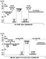
도 5는 본 발명의 제1 실시 예에 따른 이물(20)이 유입된 이어폰 장치(200) 삽입 이전 및 이후 상태에 따른 검출 값을 나타낸 도면이다.5 is a view showing detection values according to a state before and after the insertion of the
특히 첫 번째 변화 그래프는 이물(20) 유입이 없는 정상 상태에서의 4극 이어폰 장치(200) 삽입에 따른 전압 변화를 나타낸 것이다. 첫 번째 변화 그래프에 도시된 바와 같이 이어폰 장치(200) 미 삽입 상태에서는 제2 풀업 저항(R2)에 연결된 풀업 전압(Vdd)이 단말 마이크 단자(171)의 전압으로 제공될 수 있다. 이때 제2 풀업 저항(R2)에 연결된 풀업 전압(Vdd)의 크기는 1.8V로 가정하기로 한다. 이에 따라 제어부(160)의 Ear_ADC 포트에는 이어폰 장치(200) 미 삽입 상태에서 1.8V가 검출될 수 있다.Particularly, the first change graph shows the change in voltage due to the insertion of the
한편 이어폰 장치(200)가 이어폰 접속 인터페이스(170)에 접속되면 이어폰 플러그(210)가 이어폰 접속 인터페이스(170)에 배치된 단말 마이크 단자(171), 단말 접지 단자(172), 단말 우측 단자(173) 및 단말 좌측 단자(174)들 중 특히 단말 접지 단자(172) 등에 접촉됨에 따라 최저 전압으로 드롭될 수 있다. 여기서 최저 전압은 0.04V로 가정하기로 한다. 이후 이어폰 장치(200)가 정상적으로 이어폰 접속 인터페이스(170)에 삽입되고, 이어폰 플러그(210) 중 이어폰 좌측 단자(214)와 단말기(100)의 이어폰 검출 단자(175)가 접촉되면, 이어폰 검출 단자(175)에 연결된 제1 비교기(71) 출력 변화가 발생하고, 이 출력 변화는 이어폰 검출 포트(Ear_Det)에 전달될 수 있다.When the
또한 이어폰 장치(200)의 정상 삽입에 따라 이어폰 마이크 단자(211)가 단말 마이크 단자(171)에 접촉되면 제어부(160)는 이어잭 키 인터럽트 포트(Ear_Jack_Remote Key_Interrupt)의 변화를 인식하여 이어폰 장치(200) 삽입을 판단할 수 있다. 여기서 이어잭 키 인터럽트 포트(Ear_Jack_Remote Key_Interrupt)와 연결되는 제2 비교기(320)의 참조 전압이 0.84 V로 제공되는 상태에서 제2 비교기(320)의 입력 전압 변화에 따라 제2 비교기(320)의 출력이 변화될 수 있다. 이어잭 키 인터럽트 포트(Ear_Jack_Remote Key_Interrupt)는 이어폰 장치(200) 삽입에 따라 이러한 제2 비교기(320)의 전압 변화를 수신할 수 있다.When the
한편 제어부(160)는 이어폰 검출 단자(175)와 연결된 이어폰 검출 포트(EAR_Det) 및 이어잭 키 인터럽트 포트(Ear_Jack_Remote Key_Interrupt)의 신호 검출을 통하여 이어폰 장치(200)가 삽입된 것으로 확인되면, 이어 마이크 바이어스 전압원(Ear_Mic_Bias)의 전압을 단말 마이크 단자(171)를 통해 이어폰 마이크 단자(211)에 공급하도록 제어할 수 있다. 여기서 이어 마이크 바이어스 전압원(Ear_Mic_Bias)의 전압을 2.8V로 가정하면, 결과적으로 단말 마이크 단자(171)에 걸리는 전압은 이어 마이크 바이어스 전압원(Ear_Mic_Bias) 전압이 마이크 모듈(230)에 마련된 소자들에 의해 전압 강하하게 되는데 예를 들면 2.57V 전압이 형성될 수 있다. 이어 마이크 바이어스 전압원(Ear_Mic_Bias) 전압은 이어폰 장치(200)가 이어폰 접속 인터페이스(170)에 삽입되어 있는 동안 이어폰 장치(200)의 마이크 모듈(230) 운용을 위하여 지속적으로 제공될 수 있다. 결국 이어폰 장치(200)가 이어폰 접속 인터페이스에 삽입되어 있는 상태에서 단말 마이크 단자(171)에는 2.57V가 유지될 수 있다.On the other hand, when it is determined that the
이어폰 장치(200)에 배치된 마이크 모듈(230)의 특정 버튼 예를 들면 Send/End key 등이 눌려지면 마이크 모듈(230)에 마련된 신호 패스 전환이 발생하고, 해당 패스에 배치된 소자들에 의하여 전압 강하가 발생할 수 있다. 즉 사용자가 마이크 모듈(230)의 특정 버튼을 활성화하는 경우, 단말 마이크 단자(171)에 형성되는 전압은 해당 버튼에 의한 전압 강하에 따라 일정 전압 강하 예를 들면 0.12V로 전압 강하될 수 있다. 이때 단말 마이크 단자(171)에 형성되는 전압은 제2 비교기(320)의 입력 전압으로 제공될 수 있으며, 제2 비교기(320)의 입력 전압 변화에 따라 제어부(160)의 이어잭 키 인터럽트 포트(Ear_Jack_Remote Key_Interrupt)에 전달되는 신호에 변화가 발생할 수 있다. 결과적으로 제어부(160)는 이어잭 키 인터럽트 포트(Ear_Jack_Remote Key_Interrupt)에 전달되는 신호 변화에 따라 마이크 모듈(230)의 버튼이 눌려진 것을 인식할 수 있다. 마이크 모듈(230)의 버튼 눌림이 해제되는 경우, 단말 마이크 단자(171)에는 이어 마이크 바이어스 전압원(Ear_Mic_Bias) 전압이 다시 공급되고 Ear_ADC 포트에 검출되는 전압은 4극 이어폰 정상 삽입에 따른 2.57V가 형성될 수 있다.When a specific button, for example, a Send / End key, of the
이어폰 장치(200)가 이어폰 접속 인터페이스(170)에서 제거되면, 이 과정에서 이어폰 좌측 단자(214)와 이어폰 검출 단자(175) 사이의 단선이 발생하고, 제1 비교기(71)의 입력 전압에 변화가 발생할 수 있다. 결과적으로 이어폰 검출 포트(EAR_Det)에는 제1 비교기(71)의 입력 전압 변화에 따른 출력이 전달된다. 한편 단말 마이크 단자(171)에 형성되는 전압은 마이크 모듈(230)의 단선에 따라 마이크 모듈(230)에 의한 전압 강하 요소가 제거되기 때문에 이어 마이크 바이어스 전압원(Ear_Mic_Bias) 전압이 온전하게 제공될 수 있다.When the
결국 단말 마이크 단자(171)에 형성되는 전압은 이어 마이크 바이어스 전압원(Ear_Mic_Bias) 전압인 2.8V가 형성될 수 있다. 이러한 이어 마이크 바이어스 전압원(Ear_Mic_Bias) 전압 또는 단말 마이크 단자(171) 전압은 제3 비교기(330)의 입력 전압으로 제공될 수 있다. 여기서 제3 비교기(330)의 참조 전압이 2.68V로 설정된 것으로 가정하면, 제3 비교기(330)의 입력 전압이 2.57V에서 2.8V로 전압 변화가 발생함에 따라 제3 비교기(330)의 출력이 변경될 수 있다.As a result, the voltage formed at the
여기서 제3 비교기(330)의 참조 전압은 이어 마이크 바이어스 전압원(Ear_Mic_Bias) 전압이 마이크 모듈(230)에 의해 전압 강하가 발생한 전압을 이어 마이크 바이어스 전압원(Ear_Mic_Bias) 전압에서 감산하고, 감산 결과의 1/2의 값과 마이크 모듈(230)에 의해 전압 강하된 이어 마이크 바이어스 전압원(Ear_Mic_Bias) 전압의 합의 값으로 결정될 수 있다. 예를 들어 이어 마이크 바이어스 전압원(Ear_Mic_Bias) 전압을 A라고 가정하고 마이크 모듈(230)에 의해 전압 강하된 이어 마이크 바이어스 전압원(Ear_Mic_Bias) 전압을 B라고 가정하면 제3 비교기(330)의 참조 전압은 다음과 같은 수학식 1에 의해 결정될 수 있다.Here, the reference voltage of the
[수학식 1][Equation 1]
제3 비교기(330) 참조 전압 = B + 1/2(A-B)
The
제3 비교기(330)의 출력 변화는 이어폰 제거 검출 포트(Ear_Remove_Interrupt)에 전달된다. 제어부(160)는 이어폰 검출 포트(EAR_Det) 및 이어폰 제거 검출 포트(Ear_Remove_Interrupt)의 신호 변화를 통하여 이어폰 장치(200)가 이어폰 접속 인터페이스(170)에서 제거된 것을 인식할 수 있다. 그러면 제어부(160)는 이어 마이크 바이어스 전압원(Ear_Mic_Bias) 전압의 공급을 해제하고 이어폰 장치(200) 해제에 따른 기능 수행 예를 들면 단말기(100)에서 수행되는 사용자 기능에 따라 본체의 스피커 기능 및 마이크 기능 중 적어도 하나를 활성화하거나, 비활성화하도록 제어할 수 있다.The output change of the
한편 이물(20)이 이어폰 접속 인터페이스(170)에 유입되면, 이어폰 검출 단자(175)와 단말 좌측 단자(174) 사이에 전기적 연결 통로가 형성된다. 이에 따라 이어폰 검출 포트(EAR_Det)의 제1 비교기(71)의 입력 전압에 변화가 발생하고 이어폰 검출 포트(EAR_Det)에는 제1 비교기(71)의 변환된 출력이 전달될 수 있다. 한편 단말 마이크 단자(171)에는 제2 풀업 저항(R2)이 연결된 풀업 전압 예를 들면 1.8V가 제공되며, 이에 따라 Ear_ADC 포트에는 1.8V가 두 번째 그래프에서와 같이 유지될 수 있다.On the other hand, when the
이물(20)이 유입된 상태에서 4극 이어폰 장치(200)가 이어폰 접속 인터페이스(170)에 접속되면, 제어부(160)는 세 번째 그래프에서와 같은 전압 변화를 통하여 이어폰 장치(200) 운용을 지원할 수 있다. 즉 제어부(160)는 이어폰 장치(200) 미 삽입 상태에서는 제2 풀업 저항(R2)에 연결된 풀업 전압 공급에 따라 1.8V를 Ear_ADC 포트로 전달받고, 이물(20)이 유입된 상태에서는 1.8V 전압 검출이 유지될 수 있다.When the
한편 이어폰 장치(200)가 삽입되면 이어폰 검출 단자(175)의 전압 변화는 이물(20)에 의하여 이미 발생한 상태이기 때문에 제2 비교기(320)의 입력 전압 변화에 따른 이어잭 키 인터럽트 포트(Ear_Jack_Remote Key_Interrupt)에 전달되는 신호 변화를 검출할 수 있다. 제어부(160)는 이어잭 키 인터럽트 포트(Ear_Jack_Remote Key_Interrupt)의 신호 변화가 발생하면 이어폰 장치(200) 삽입으로 인식하고 이어 마이크 바이어스 전압원(Ear_Mic_Bias) 전압을 단말 마이크 단자(171)에 공급하도록 제어할 수 있다.On the other hand, when the
결국 이어폰 장치(200)에 연결된 마이크 모듈(230)이 이어 마이크 바이어스 전압원(Ear_Mic_Bias) 전압을 전압 강하하기 때문에 Ear_ADC 포트에는 앞서 가정한 2.57V가 검출될 수 있다. 제어부(160)는 해당 전압 유지 시 4극 이어폰 정상 삽입 상태로 판단하고 그에 따른 이어폰 장치(200) 기능을 운용하도록 제어할 수 있다. 한편 이어폰 장치(200)가 이어폰 접속 인터페이스(170)에서 제거되면, 이어폰 검출 포트(EAR_Det)의 전압 변화는 발생하지 않고, 제3 비교기(330)의 입력 전압 변화에 따라 이어폰 제거 검출 포트(Ear_Remove_Interrupt)의 전압 변화가 발생한다. 제어부(160)는 이어폰 제거 검출 포트(Ear_Remove_Interrupt) 전압 변화 발생 시 이어폰 장치(200) 삽입 해제로 판단하고, 이어 마이크 바이어스 전압원(Ear_Mic_Bias)의 전압 공급을 중지하도록 제어할 수 있다.As a result, since the
상술한 바와 같이 본 발명의 이어폰 접속 인터페이스(170)는 단말 마이크 단자(171)에 풀업 전압을 제공하고, 이어잭 키 인터럽트 포트(Ear_Jack_Remote Key_Interrupt)의 전압 변화 발생에 따라 이물(20) 유입에 관계없이 이어폰 장치(200) 삽입을 정상적으로 인식할 수 있도록 지원한다. 그리고 본 발명의 이어폰 접속 인터페이스(170)는 이어폰 제거 검출을 위한 제3 비교기(330) 배치를 통하여 이어폰 제거 시 전압 변화를 검출하고 그에 따른 단말기 동작 제어를 수행하도록 지원한다.As described above, the
한편 상술한 설명에서는 4극 이어폰 삽입 및 운용에 대해서만 설명하였으나, 본 발명이 이에 한정되는 것은 아니다. 즉 본 발명의 이어폰 접속 인터페이스(170)는 3극 이어폰이 삽입되어도 이물(20) 유입에 관계없이 정상 동작을 수행할 수 있다. 3극 이어폰의 경우 이어폰 마이크 단자가 별도 마련되지 않고, 이어폰 마이크 단자 영역이 이어폰 접지 단자에 포함되도록 설계된다.In the above description, only the insertion and operation of the four-pole earphone has been described, but the present invention is not limited thereto. That is, the
도 6은 이물 유입 이전 이후 상태에서의 3극 이어폰 접속에 따른 변화 값 검출을 나타낸 도면이다.FIG. 6 is a diagram showing change value detection according to triode earphone connection in a state after foreign matter is introduced. FIG.
도 6을 참조하면, 이물이 유입되지 않은 상황에서 이어폰 접속 인터페이스(170)의 3극 이어폰 장치 접속 전후 변화는 첫 번째 그래프와 같은 변화를 가질 수 있다. 이를 보다 상세히 설명하면, 이어폰 접속 인터페이스(170)의 단말 마이크 단자(171)와 연결된 Ear_ADC 포트는 제2 풀업 저항(R2)이 배치된 풀업 전압에 의하여 3극 이어폰 장치 삽입 이전에 1.8V 전압을 검출할 수 있다. 이후 3극 이어폰 장치가 본 발명의 이어폰 접속 인터페이스(170)에 삽입되면, 단말 마이크 단자(171)는 3극 이어폰 장치의 이어폰 접지 단자와 연결될 수 있다. 결과적으로 Ear_ADC 포트에는 최소 전압 예를 들면, 0.04V가 검출될 수 있다. 이때, 마이크 지원 회로(300)는 이어폰 검출 포트(EAR_Det) 및 이어잭 키 인터럽트 포트(Ear_Jack_Remote Key_Interrupt)의 전압 상태 변화가 동시에 발생함을 감지할 수 있다. 한편 단말기(100)는 접속된 이어폰 장치의 극수 확인을 위하여 이어 마이크 바이어스 전압원(Ear_Mic_Bias)의 전압을 공급한다. 이에 따라 Ear_ADC 포트에는 이어 마이크 바이어스 전압원(Ear_Mic_Bias)의 전압이 형성되어 2.57V가 검출될 수 있다. 이후 제어부(160)는 3극 이어폰 장치 접속을 확인하고 이어 마이크 바이어스 전압원(Ear_Mic_Bias)의 전압을 차단하게 되며, 이에 따라 Ear_ADC 포트에는 접지 단자 연결에 따라 검출되는 최소 전압 즉 0.04V가 검출될 수 있다.Referring to FIG. 6, the change of the
한편 3극 이어폰 장치가 이어폰 접속 인터페이스(170)에서 제거되면, 다시 풀업 전압이 단말 마이크 단자(171)에 공급됨에 따라 Ear_ADC 포트에는 1.8V의 전위가 형성될 수 있다. 이때 이어폰 검출 포트(EAR_Det) 및 이어잭 키 인터럽트 포트(Ear_Jack_Remote Key_Interrupt)의 전압 상태 변화가 동시에 발생한다. 제어부(160)는 상술한 포트들의 전압 상태 동시 변화를 기준으로 3극 이어폰 장치 삽입 해제를 판단할 수 있다.Meanwhile, when the triode earphone device is removed from the
한편 이물이 유입된 상황에서 3극 이어폰 장치가 삽입된 경우 도 6의 두 번째 그래프와 같은 신호 변화가 발생할 수 있다. 즉 이물이 유입된 상황에서 3극 이어폰 장치의 경우 실질적으로 이물이 유입되지 않은 상황과 다르지 않은 상태 변화를 가질 수 있다. 특히 이어폰 미 삽입 상태에서 이물이 유입되더라도 마이크 지원 회로(300)의 이어폰 검출 포트(EAR_Det)에는 전압 상태가 변화하지만, 이어잭 키 인터럽트 포트(Ear_Jack_Remote Key_Interrupt)의 전압 상태 변화는 발생하지 않는다. 그리고 3극 이어폰 장치가 이어폰 접속 인터페이스(170)에 삽입되면, 이어잭 키 인터럽트 포트(Ear_Jack_Remote Key_Interrupt)에 전압 변화가 발생한다. 이러한 전압 변화는 3극 이어폰 장치의 이어폰 접속 인터페이스(170)의 접속 해제 시에도 발생하게 된다. 이에 따라 단말기(100)의 제어부는 이어잭 키 인터럽트 포트(Ear_Jack_Remote Key_Interrupt)의 전압 변화를 통하여 3극 이어폰 장치 접속 해제를 판별하고 그에 따른 기능 수행을 지원할 수 있다. 상술한 같이 본 발명의 이어폰 접속 인터페이스(170)를 가지는 단말기(100)는 이물 유입에 관계없이 3극 이어폰 장치의 접속을 정상 처리할 수 있도록 지원한다.On the other hand, in the case where a three-pole earphone is inserted in a state where a foreign object is introduced, a signal change as shown in the second graph of FIG. 6 may occur. That is, in the case of a foreign matter, the three-pole earphone device may have a state change that is not different from a situation in which the foreign matter is not substantially introduced. Particularly, even if a foreign object flows in the earphone non-inserted state, the voltage state changes in the earphone detection port EAR_Det of the
한편 상술한 설명에서 일정 전압 수치를 언급하긴 하였으나 본 발명이 상술한 특정 수치의 전압에 한정되는 것은 아니다. 즉 상술한 각 전압 수치들은 단말기(100) 별로 적용되는 풀업 전압 또는 이어 마이크 바이어스 전압원의 전압 변경 등에 따라 달라질 수 있다. 또한 각 비교기의 성능에 따라 비교기의 참조 전압 역시 변경될 수 있을 것이다.Although the above description refers to the constant voltage value, the present invention is not limited to the voltage of the specific value mentioned above. That is, the above-described voltage values may vary depending on the pull-up voltage applied to each terminal 100 or the voltage change of the ear microphone bias voltage source. Also, the reference voltage of the comparator can be changed according to the performance of each comparator.
도 7은 본 발명의 제2 실시 예에 따른 이어폰 접속 검출을 수행할 수 있는 단말기(100)의 이어폰 접속 인터페이스(170) 구조를 보다 상세히 나타낸 도면이다.7 is a more detailed view of the structure of the
도 7을 참조하면, 본 발명의 이어폰 접속 인터페이스(170)는 도시된 바와 같이 단말 마이크 단자(171), 단말 접지 단자(172), 단말 좌측 단자(174), 단말 우측 단자(173) 및 이어폰 검출 단자(175)를 포함하며, 특히 단말 접지 단자(172)의 동일 선상에 정렬 배치되는 단말 접지 검출 단자(177)를 포함할 수 있다.7, the
이어폰 검출 단자(175)는 단말 좌측 단자(174)와 정렬 배치된다. 이에 따라 이어폰 장치(200)가 이어폰 접속 인터페이스(170)에 삽입되면 이어폰 검출 단자(175)와 단말 좌측 단자(174)는 각각 이어폰 장치(200)의 이어폰 좌측 단자(214)에 접촉될 수 있다. 이어폰 검출 단자(175)에는 제1 풀업 저항(R1)이 연결된 풀업 전압이 공급되며, 이러한 풀업 전압은 제1 비교기(71)의 입력 전압이 된다. 이에 따라 이어폰 검출 단자(175)에 이어폰 좌측 단자(214)가 접촉되면 제1 비교기(71)의 입력 전압에 변화가 발생하여 제1 비교기(71)의 출력이 변경될 수 있다.The
단말 마이크 단자(171)는 마이크 지원 회로(300)를 통하여 제어부(160)에 연결되며 이어폰 마이크 단자(211) 연결 시 이어 마이크 기능 지원을 위한 신호 송수신을 지원한다. 마이크 지원 회로(300)는 단말 마이크 단자(171)에 연결되는 Ear_Mic_P 포트와 Ear_Mic_N 포트, 단말 마이크 단자(171)와 이어 마이크 바이어스 전압원(Ear_Mic_Bias) 사이에 연결되는 필터(310), 단말 마이크 단자(171)와 이어잭 키 인터럽트 포트(Ear_Jack_Remote Key_Interrupt) 사이에 배치되는 제2 비교기(320)를 포함할 수 있다.The
단말 좌측 단자(174)는 제어부(160)의 이어폰 좌측 포트(EAR_SPK_L)에 연결되며, 단말 우측 단자(173)는 제어부(160)의 이어폰 우측 포트(EAR_SPK_R)에 연결될 수 있다. 제어부(160)는 이어폰 장치(200) 삽입을 인식하면 단말 좌측 단자(174)에 오디오 신호를 출력하고, 이 오디오 신호는 단말 좌측 단자(174)에 연결된 이어폰 좌측 단자(214)에 전달될 수 있다. 또한 제어부(160)는 이어폰 장치(200) 삽입을 인식하면 단말 우측 단자(173)에 오디오 신호를 출력하며, 이 오디오 신호는 단말 우측 단자(173)에 연결된 이어폰 우측 단자(213)에 전달될 수 있다.The terminal left terminal 174 may be connected to the earphone left port EAR_SPK_L of the
특히 본 발명의 제2 실시 예에 따른 이어폰 접속 인터페이스(170)는 별도로 마련된 단말 접지 검출 단자(177)를 더 포함하며, 단말 접지 검출 단자(177)는 도시된 바와 같이 게이트(73)를 통하여 이어폰 검출 포트(EAR_Det)에 연결될 수 있다. 한편 제1 비교기(71)의 출력 또는 게이트(73)를 통하여 이어폰 검출 포트(EAR_Det)에 연결될 수 있다. 여기서 게이트(73)는 XOR 게이트로서 입력되는 제1 비교기(71)의 출력 및 단말 접지 검출 단자(177)에 형성되는 전압의 크기에 따라 이어폰 검출 포트(EAR_Det)에 특정 전압 레벨의 신호가 전달될 수 있다.In particular, the
게이트(73)의 입력단으로 배치된 A, B 지점에 대한 게이트(73) 출력은 다음 표 1과 같다. 여기서 A 및 B 지점 사이에는 제3 저항(R3)이 배치될 수 있다.The output of the
상술한 표 1에 대하여 보다 상세히 설명하면, 먼저 이어폰 접속 인터페이스(170)에 이어폰 장치(200) 삽입이 없고 이물(20) 유입도 없는 경우 A 및 B 지점은 각각 Low 상태의 값에 따라 논리 값으로 "0"의 값들을 가질 수 있다. 이를 위하여 제1 비교기(71)는 이어폰 장치(200)나 이물(20) 유입이 없는 경우 Low 신호가 출력되도록 설계될 수 있다.If the
한편 이물(20)이 유입되면, 이어폰 검출 단자(175)와 단말 좌측 단자(174)가 연결되며 이에 따라 풀업 전압이 이어폰 검출 단자(175)와 이물(20) 및 단말 좌측 단자(174)를 포함하는 패스를 통하게 된다. 결과적으로 제1 비교기(71)의 입력 전압에 변화가 발생하고 제1 비교기(71)는 이러한 변화에 따라 이전과 다른 출력 즉 High 신호를 출력할 수 있다. 이 High 신호는 A 지점의 전압을 논리 값으로 "1"의 값을 가지도록 형성한다.The
한편 이어폰 접속 인터페이스(170)에 실제 이어폰 장치(200) 삽입이 없는 상태이기 때문에 단말 접지 검출 단자(177)는 개방 상태 또는 플로팅(Floating) 상태를 가지게 되며 이에 따라 B 지점은 A 지점의 전압 값을 따르게 되어 논리 값이 "1"을 가지게 된다. 결과적으로 게이트(73)의 입력단이 모두 "1"의 값을 가지게 되며, 이에 따라 게이트(73) 출력은 "0"의 값을 가진다. 이어폰 검출 단자(175)는 논리 값 "0"이 전달되면 이어폰 장치 미 삽입 상태 또는 이물(20) 유입 상태로 판단하고 이어폰 기능을 지원하지 않도록 지원할 수 있다.Since the
이어폰 장치(200)가 이어폰 접속 인터페이스(170)에 접속되면 제1 비교기(71)의 출력은 변경되며, 또한 단말 접지 검출 단자(177)는 단말 접지 단자(172)에 연결되어 접지 상태를 가질 수 있다. 결국 단말 접지 검출 단자(177)에 연결되는 B 지점은 접지에 의하여 Low 상태를 가지며 이에 따라 게이트(73)의 입력단에는 각각 논리 값 "1" 및 "0"의 신호가 입력될 수 있다. 게이트(73) 출력은 입력단에 형성된 논리 값에 따라 "1"의 값을 출력하며, 제어부(160)는 이어폰 검출 포트(EAR_Det)에 "1"에 해당하는 신호가 전달되면 이어폰 장치(200) 삽입으로 인식하고 이이폰 기능 지원을 수행할 수 있다.When the
상술한 바와 같이 본 발명의 실시 예에 따른 이어폰 운용 시스템(10)은 이어폰 접속 인터페이스(170)에 단말 접지 검출 단자(177)와 게이트(73)를 배치함으로써 이물(20) 유입 상태에서도 이어폰 장치(200) 미삽입으로 인식하고 그에 따른 기능 수행을 지원할 수 있다.As described above, the
한편 상술한 설명에서 본 발명의 이어폰 접속 인터페이스(170)에 배치되는 단자들의 배치는 앞서 언급한 바와 같이 단말 마이크 단자와 단말 접지 단자의 위치가 판매 지역 등에 따라 변경될 수 있다. 즉 이어폰 접속 인터페이스(170)는 단말 마이크 단자가 단말 접지 단자보다 단말 우측 단자에 인접된 위치에 배치되도록 설계될 수 있다. 또한 이어폰 접속 인터페이스(170)는 단말 접지 단자가 단말 마이크 단자보다 단말 우측 단자에 인접된 위치에 배치될 수도 있다. 이에 따라 본 발명의 이어폰 접속 인터페이스(170)에서 단말 접지 검출 단자(177)의 위치 또한 단말 접지 단자의 위치 변화에 따라 다르게 설계될 수도 있을 것이다. 따라서 본 발명의 단말 접지 검출 단자(177)의 위치에 한정되는 것이 아니라, 이물 유입됨에 따라 전기적 연결이 형성될 수 있는 이어폰 접속 인터페이스(170)의 홀 밑단으로부터 일정 거리 이격된 위치에 이어폰 장치 접속을 인식할 수 있는 단자가 추가 마련되는 구성으로서 이해되어야 할 것입니다. 또는 별도 단자의 추가 없이 홀 밑단으로부터 일정 거리 이격된 위치의 단말 단자들의 신호 변화를 통하여 이어폰 장치의 정상 동작 지원을 위한 기술로 이해되어야 할 것이다.Meanwhile, in the above description, the positions of the terminals disposed in the
도 8은 본 발명의 제3 실시 예에 따른 이어폰 접속 검출을 수행할 수 있는 단말기(100)의 이어폰 접속 인터페이스(170) 구조를 보다 상세히 나타낸 도면이다.FIG. 8 is a diagram illustrating a detailed structure of an
도 8을 참조하면, 본 발명의 제3 실시 예에 따른 이어폰 접속 인터페이스(170)는 단말 마이크 단자(171), 단말 접지 단자(172), 단말 우측 단자(173), 단말 좌측 단자(174), 이어폰 검출 단자(175)를 포함하며, 단말 접지 단자(172)에 정렬 배치되는 단말 접지 검출 단자(177)를 포함할 수 있다.8, the
단말 마이크 단자(171)는 앞서 도 6에서 설명한 마이크 지원 회로(300)를 통하여 제어부(160)에 연결된다. 이러한 단말 마이크 단자(171)는 제어부(160) 제어에 따라 마이크 기능 지원을 위한 신호 송수신을 수행하는 통로 역할을 수행한다. 단말 우측 단자(173)는 제어부(160)의 이어폰 우측 포트(EAR_SPK_R)에 연결되며, 단말 좌측 단자(174)는 제어부(160)의 이어폰 좌측 포트(EAR_SPK_L)에 연결될 수 있다.The
이어폰 검출 단자(175)는 제1 풀업 저항(R1)이 연결된 풀업 전압이 제공되며, 제1 비교기(71)의 입력단에 연결될 수 있다. 제1 비교기(71)의 출력은 이어폰 검출 포트(EAR_Det)에 전달된다.The
단말 접지 검출 단자(177)에는 제3 풀업 저항(R4)을 통해 풀업 전압이 제공된다. 그리고 단말 접지 검출 단자(177)는 제어부(160)의 접지 단자 검출 포트(GND_Open_Det)에 연결된다. 이에 따라 단말 접지 검출 단자(177)에 이어폰 장치(200)가 삽입되면 접지 단자 검출 포트(GND_Open_Det)에 전압 변화가 발생하고, 제어부(160)는 접지 단자 검출 포트(GND_Open_Det) 확인을 통하여 이어폰 장치(200) 삽입을 확인할 수 있다. 이러한 본 발명의 제3 실시 에에 따른 이어폰 접속 인터페이스(170)의 이어폰 장치 검출은 다음 표 2와 같다.The terminal
상술한 표 2에서와 같이 이어폰 장치(200) 삽입을 이어폰 검출 단자(175)와 단말 접지 검출 단자(177)의 전압 변화를 통하여 확인함으로써 이물(20) 유입에 따른 오동작을 방지하고, 이어폰 장치(200) 삽입에 따른 정확한 인식을 통하여 이어폰 기능을 지원할 수 있다.The insertion of the
한편, 이물(20)은 도 9에 도시된 바와 같이 이어폰 접속 인터페이스(170)에 일정 부분 이상 충진될 수도 있다. 이 경우 앞서 설명한 다양한 실시 예에 적용되는 회로가 적용되기 어려울 수 있다. 즉 단말 접지 검출 단자(177)가 이물(20) 유입에 따른 정상 동작을 수행하지 못할 수 있다. 이를 보완하기 위하여, 본 발명의 이어폰 접속 인터페이스(170)는 도 9에 도시된 바와 같이 제4 비교기(79) 및 제4 비교기(79)의 비교 전압으로 이용되는 일정 전압 Vdd를 분배하는 분배 저항들(R5, R6)이 더 마련될 수 있다. 결과적으로 단말 접지 검출 단자(177)와 제3 풀업 저항(R4) 사이의 전압을 제1 입력 값으로 하며, 분배 저항들(R5, R6)에 의해 일정 전압 Vdd를 분배한 비교 전압의 비교를 통하여 제4 비교기(79)의 출력이 결정될 수 있다. 제4 비교기(79)의 출력은 제어부(160)의 GND_DET 포트에 전달될 수 있다. 여기서 GND_DET 포트는 이전 실시 예들에서 설명한 GND_OPEN_DET 포트와 동일한 포트이며, 다만 명칭을 다르게 할당한 것이다.On the other hand, the
이물(20)이 도시된 바와 같이 이어폰 접속 인터페이스(170)에 충진되며, 해당 이물(20)은 단말 접지 검출 단자(177)에 대하여 일정 저항으로 작용하게 된다. 여기서 이물(20)은 그 특성에 따라 저항값이 다르게 형성될 수 있다. 예를 들어 수돗물의 경우 180K옴의 저항값을 가질 수 있으며, 바닷물이나 소금물의 경우 20K옴의 저항값을 가질 수 있다. 결과적으로 제4 비교기(79)의 제1 입력 값이 이전 풀업 전압(Vdd) 상태에서 이물(20)에 의한 분배 전압으로 변경될 수 있다. 제4 비교기(79)는 제1 입력 값과 비교 전압을 비교하되, 제1 입력 값이 비교 전압에 비하여 높은 경우 이전 출력 신호와 동일한 신호의 출력을 유지할 수 있으며, 제1 입력 값이 비교 전압에 비하여 낮은 경우 이전 출력 신호와 다른 출력 신호를 출력할 수 있다. 이어폰 플러그(210)가 이어폰 접속 인터페이스(170)에 삽입되면, 단말 접지 검출 단자(177)의 전위는 접지 전위로 떨어지기 때문에 제4 비교기(79)의 제1 입력 값의 전위는 접지 전위가 될 수 있다. 한편 이어폰 접속 인터페이스(170)에 이물이 삽입되면 제4 비교기(79)의 제1 입력 값의 전위는 접지 전위보다는 높은 전위를 형성된다. 이에 따라 제4 비교기(79)의 비교 전압이 접지 전위보다는 높고 풀업 전압(Vdd)보다는 낮은 전압 사이의 일정 전압이 되도록 분배 저항들(R5, R6)의 저항 값이 결정될 수 있다. 이 분배 저항들(R5, R6)은 이용하는 일정 전압의 크기에 따라 달라질 수 있기 때문에 각 이어폰 접속 인터페이스(170)의 특성에 따라 변경될 수 있을 것이다.The
상술한 바와 같이 본 발명의 이어폰 접속 인터페이스(170)의 구조는 이물(20)이 유입되더라도 적절한 형태의 신호 전달을 통하여 이어폰 플러그의 삽입과 구분될 수 있도록 지원할 수 있다.As described above, the structure of the
도 10은 본 발명의 실시 예에 따른 단말기 구조를 보다 상세히 나타낸 도면이다.10 is a detailed diagram illustrating a terminal structure according to an embodiment of the present invention.
도 10을 참조하면, 본 발명의 단말기(100)는 통신부(110), 입력부(120), 오디오 처리부(130), 표시부(140), 저장부(150) 및 제어부(160)를 포함하여 이어폰 장치(200) 삽입을 위한 이어폰 접속 인터페이스(170)를 포함할 수 있다. 여기서 상기 단말기(100)의 구성 중 통신부(110)의 구성은 단말기(100)가 통신 기능을 지원하지 않는 경우 생략될 수도 있다. 입력부(120)는 단말기(100) 운용을 위한 입력 신호를 생성하는 구성으로서, 버튼이나 키, 사이드 키 등으로 마련될 수 있다. 여기서 표시부(140)가 터치스크린 형태로 마련되는 경우 표시부(140)는 입력부 역할을 수행할 수 있다.10, a terminal 100 according to the present invention includes a
상술한 본 발명의 단말기(100)는 이어폰 장치(200)가 이어폰 접속 인터페이스(170)에 접속되는 경우, 해당 이어폰 장치(200)의 삽입을 인식하고, 이어폰 장치(200)와 관련된 기능 지원을 수행할 수 있다. 이때 이어폰 접속 인터페이스(170)는 이어폰 삽입 검출을 위한 두 개의 검출자들을 이용할 수 있도록 지원한다. 즉 이어폰 접속 인터페이스(170)는 앞서 설명한 바와 같이 이어폰 검출 단자(175)에 해당하는 제1 검출자와, 단말 마이크 단자(171)에 마련된 회로들을 포함하는 제2 검출자를 마련하거나, 단말 접지 검출 단자(177)에 해당하는 제2 검출자를 마련할 수 있다. 그러면 제어부(160)는 제1 검출자 및 제2 검출자의 전압 변화 상태를 파악하여 현재 상태가 이물(20) 유입 상태인지 또는 이어폰 장치(200) 삽입 상태인지, 이물(20) 유입된 상태에서 이어폰 장치(200) 삽입 상태인지 등을 확인할 수 있다. 그리고 제어부(160)는 이물(20) 유입된 상태인 경우 별도의 이어폰 기능 지원을 수행하지 않도록 지원할 수 있으며, 이어폰 장치(200)가 삽입된 상태인 경우 이어폰 기능을 정상적으로 수행되도록 제어할 수 있다.When the
한편 상술한 설명에서 제2 검출자는 단말 마이크 단자(171)에 연결되는 회로를 포함하는 구성이거나, 단말 접지 검출 단자(177)에 연결되는 회로를 포함하는 구성으로서 설명하지만 본 발명이 이에 한정되는 것은 아니다. 즉 설계 방식에 따라 단말 우측 단자(173)에 정렬되는 단말 우측 검출 단자를 단말 접지 검출 단자(177)와 유사한 방식으로 배치할 수 있다. 이 경우 제2 검출자는 단말 우측 검출 단자와 이를 포함하는 회로의 구성이 될 수 있다.On the other hand, in the above description, the second detector is configured to include a circuit connected to the
따라서 본 발명의 이어폰 접속 인터페이스(170)는 이어폰 장치(200)가 삽입되는 환경에서 적어도 두 개의 검출자를 마련하고, 각 검출자들의 전압 변화 상태를 기반으로 이어폰 장치(200)의 정상 삽입 상태를 파악하고 그에 따른 이어폰 기능 운용을 지원하는 기술로 이해될 수 있을 것이다.Therefore, the
오디오 처리부(130)는 단말기(100)의 오디오 신호 출력을 위한 스피커(SPK) 및 오디오 신호 수집을 위한 마이크(MIC)를 포함할 수 있다. 이러한 오디오 처리부(130)는 이어폰 접속 인터페이스(170)에 이어폰 장치(200)가 삽입되면 스피커(SPK) 및 마이크(MIC) 기능을 턴-오프 하도록 제어하고, 해당 기능을 이어폰 장치(200)를 기반으로 수행되도록 오디오 신호 패스(Path) 전환을 수행할 수 있다. 그리고 오디오 처리부(130)는 이어폰 장치(200)가 이어폰 접속 인터페이스(170)로부터 제거되거나 이어폰 장치(200) 미접속 상태이면, 단말기(100) 본체의 스피커(SPK) 및 마이크(MIC) 기능을 턴-온하도록 오디오 신호 패스의 원래 상태로의 복귀 또는 원래 상태의 오디오 패스 유지를 제어할 수 있다. 이때 오디오 처리부(130)는 제어부(160) 제어에 따라 현재 활성화되고 있는 사용자 기능이 요구하는 스피커(SPK) 및 마이크(MIC) 중 적어도 하나를 활성화하도록 지원한다.The
표시부(140)는 단말기(100)의 사용자 기능 운용에 따른 다양한 화면을 출력할 수 있다. 특히 표시부(140)는 이어폰 접속 인터페이스(170)에 이어폰 장치(200)가 삽입되거나 이물(20)이 유입된 경우 그에 따른 각각의 구분된 알람 등을 출력할 수 있다. 이를 위하여 제어부(160)는 앞서 설명한 제1 검출자 및 제2 검출자의 전압 변화를 확인하고, 이어폰 접속 인터페이스(170)에 이물(20)이 유입된 상태로 판단되면, 표시부(140)에 이어폰 접속 인터페이스(170)에 이물(20)이 유입되었음을 알리는 팝업을 출력하도록 제어하거나 메시지를 출력하도록 제어할 수 있다. 그리고 제어부(160)는 이어폰 접속 인터페이스(170)에 삽입된 이물 제거를 위한 사전 정의된 안내 정보를 표시부(140)에 출력하도록 제어할 수 있다. 상술한 표시부(140)는 상기 이어폰 장치(200) 삽입 또는 해제, 상기 이물 유입, 상기 유입된 이물의 제거, 상기 이물 유입된 상태에서 이어폰 장치 삽입 또는 해제에 따른 안내 메시지를 출력할 수 있다. 여기서 안내 메시지는 텍스트나 특정 화면이나 특정 아이콘 중 적어도 하나를 포함할 수 있으며, 추가로 오디오 처리부(130)에 전달될 음성 파일을 포함할 수도 있다. 이를 통하여 사용자는 단말기(100)가 현재 어떠한 상태로 운용되는지를 적절히 인지할 수 있다. 추가로 표시부(140)는 이물 유입된 상태에 대한 메시지나 이미지 등을 다양하게 제공할 수 있다. 즉 제어부(160)는 이어폰 접속 인터페이스(170)로부터 전달되는 신호 값들을 기반으로 이어폰 검출 단자(Ear_DET)가 배치된 부위에만 이물(20)이 유입되어 있는 상태인지, 이어폰 접속 인터페이스(170) 전반에 걸쳐 이물(20)이 유입되어 있는 상태인지 등을 구분할 수 있다. 이에 따라 표시부(140)는 제어부(160) 제어에 따라 이물(20)이 충진된 상태 즉 일부 충진 또는 전부 충진 등을 구분할 수 있는 메시지나 이미지를 출력할 수 있다.The
한편 제어부(160)는 이어폰 접속 인터페이스(170)에 이어폰 장치(200)가 삽입되면, 이어폰 장치(200) 삽입 인식을 표시부(140) 및 오디오 처리부(130) 중 적어도 하나를 통해 안내할 수 있다. 그리고 제어부(160)는 이어폰 장치(200) 삽입을 통하여 수행될 수 있는 사용자 기능 목록을 표시부(140)에 출력하도록 지원할 수 있다. 한편 제어부(160)는 오디오 신호 출력 기능을 지원하는 특정 사용자 기능이 활성화된 상태에서 이어폰 접속 인터페이스(170)에 이어폰 장치(200)가 삽입되면 오디오 처리부(130)의 스피커(SPK)를 통하여 출력되는 오디오 신호의 스피커(SPK) 출력을 중지하고, 해당 오디오 신호가 이어폰 장치(200)를 통하여 출력되도록 제어할 수 있다.Meanwhile, when the
도 11은 본 발명의 실시 예에 따른 이어폰 운용 시스템의 구성에 있어서 이물(20) 유입에 관계없이 이어폰 장치(200) 접속 및 해제의 정상 인식을 위한 방법을 설명하기 위한 도면이다. 이하 설명에서 이어폰 운용 시스템(10)은 이어폰 장치 접속을 인식하기 위하여 앞서 설명한 이어폰 접속 인터페이스에 배치된 단말 단자들 중 일부 단자들을 각각 제1 검출자와 제2 검출자로서 명명하여 설명하기로 한다.11 is a diagram for explaining a method for recognizing normal connection and disconnection of the
도 11을 참조하면, 단말기(100)의 제어부(160)는 전원이 공급되면 단말기(100) 각 구성에 필요한 전원을 분배하고 사용자 기능 지원을 위하여 901 단계에서와 같이 대기 상태를 유지할 수 있다. 이 단계에서 제어부(160)는 입력부(120) 또는 입력 기능의 표시부(140)로부터 특정 사용자 기능 활성화를 위한 입력 신호가 발생하면 해당 입력 신호에 따라 사용자 기능을 활성화하도록 지원할 수 있다.Referring to FIG. 11, the
한편 제어부(160)는 903 단계에서 이어폰 접속 인터페이스(170)에서 이어폰 장치(200) 접속을 인식하기 위해 마련된 제1 검출자가 제1 설정 값을 가지는지 여부를 확인할 수 있다. 이 단계에서 제1 검출자가 제1 설정 값을 가지지 않는 경우 제어부(160)는 905 단계로 분기하여 단말기 종료를 위한 입력 신호 발생 여부를 확인하고, 해당 입력 신호 발생이 없는 경우 901 단계로 분기하여 대기 상태 또는 특정 사용자 기능 운용 상태를 지원할 수 있다. 여기서 제1 검출자는 앞서 설명한 이어폰 검출 단자(175) 및 그와 연결된 회로 구성이 될 수 있다. 그리고 제1 설정 값은 제1 검출자에 제공된 전압이 변화를 가짐에 따른 특정 전압 레벨이 될 수 있다. 결과적으로 제1 검출자가 제1 설정 값과 동일한 경우는 이물(20) 유입에 따라 이어폰 검출 단자(175)에 제공되는 풀업 전압이 변화되는 것을 의미할 수 있을 것이다.The
한편 903 단계에서 이어폰 접속 인터페이스(170)에 마련된 제1 검출자가 제1 설정 값을 가지는 경우, 제어부(160)는 907 단계로 분기하여 제2 검출자가 제2 설정 값을 가지는지를 확인할 수 있다. 여기서 제2 검출자는 다양한 실시 예들에서 언급한 단말 마이크 단자(171) 및 그에 연결되는 회로, 단말 접지 검출 단자(177) 및 그에 연결되는 회로 등이 될 수 있다. 또한 제2 검출자는 설계자 의도에 따라 단말 우측 검출 단자가 단말 접지 검출 단자(177)를 대신하여 마련되는 경우 단말 우측 검출 단자가 될 수도 있을 것이다. 제2 검출자가 제2 설정 값을 가지는 의미는 제2 검출자에 제공되는 전압이 변화되어 특정 전압 레벨이 되는 것을 의미할 수 있다. 즉 이어폰 장치(200) 삽입에 따라 제2 검출자에 제공되는 전압에 변화가 발생한 경우가 될 수 있다. 제어부(160)는 907 단계에서 제2 검출자가 이어폰 장치(200) 삽입에 해당하는 제2 설정 값을 가지지 못하는 경우 911 단계로 분기하여 이물(20) 유입에 따른 상태임을 확정할 수 있다. 이 경우 제어부(160)는 이물(20) 유입에 따른 안내 메시지를 표시부(140) 및 오디오 처리부(130) 중 적어도 하나를 통하여 출력할 수 있다.On the other hand, if the first detector provided in the
한편 907 단계에서 제2 검출자가 제2 설정 값을 가지는 경우 즉 이어폰 장치(200) 삽입에 따라 제2 검출자가 기 정의된 특정 전압 레벨을 가지는 경우 제어부(160)는 909 단계로 분기하여 이어폰 장치(200) 인식 및 이어폰 장치(200) 접속에 따른 기능 수행을 지원할 수 있다. 즉 제어부(160)는 이어폰 장치(200) 접속에 따라 단말기(100)에서 생성된 오디오 신호를 이어폰 장치(200)를 통하여 출력되도록 오디오 패스 전환을 수행할 수 있으며, 이어폰 장치(200)가 4극 이어폰인 경우 마이크 신호를 수집하여 처리하도록 지원할 수 있다. 한편 제어부(160)는 이물이 유입되더라도 검출자들의 전기적 변화 검출을 통하여 이어폰 장치(200) 미접속 상태인 경우 단말기(100)를 통한 오디오 신호의 출력에 해당하는 오디오 패스를 유지하도록 제어할 수 있다.On the other hand, if the second detector has the second set value in
한편 상기 제어부(160)는 상술한 제1 검출자 및 제2 검출자의 전압 레벨 변화에 따른 설정 값 확인을 위하여 각 검출자들과 연결되는 포트를 마련할 수 있다.Meanwhile, the
이상에서 설명한 바와 같이 본 발명의 실시 예에 따른 이어폰 운용 시스템(10)의 이어폰 접속 인터페이스 및 이어폰 운용 방법과, 이를 지원하는 단말기에 따르면 본 발명의 이어폰 접속 인터페이스(170)에 이물(20)이 유입되더라도 정상적인 이어폰 장치(200) 인식을 수행할 수 있으며, 그에 따른 정상적인 이어폰 장치(200) 기반 기능 운용을 지원할 수 있다. 이를 위하여 본 발명은 이어폰 접속 인터페이스의 밑단의 제1 영역에 배치되어 전기적 변화를 검출할 수 있는 제1 검출자와, 밑단으로부터 일정 간격 이격된 위치의 제2 영역에 배치되어 이어폰 접속에 따른 전기적 변화를 검출할 수 있는 제2 검출자를 포함한다.As described above, according to the earphone connecting interface and earphone operating method of the
한편 상술한 단말기(100)는 그 제공 형태에 따라 다양한 추가 모듈을 더 포함할 수 있다. 즉 상기 단말기(100)는 통신 단말기인 경우 근거리 통신을 위한 근거리통신모듈, 상기 단말기(100)의 유선통신방식 또는 무선통신방식에 의한 데이터 송수신을 위한 인터페이스, 인터넷 네트워크와 통신하여 인터넷 기능을 수행하는 인터넷통신모듈 및 디지털 방송 수신과 재생 기능을 수행하는 디지털방송모듈 등과 같이 상기에서 언급되지 않은 구성들을 더 포함할 수도 있다. 이러한 구성 요소들은 디지털 기기의 컨버전스(convergence) 추세에 따라 변형이 매우 다양하여 모두 열거할 수는 없으나, 상기 언급된 구성 요소들과 동등한 수준의 구성 요소가 상기 디바이스에 추가로 더 포함되어 구성될 수 있다. 또한 본 발명의 단말기(100)는 그 제공 형태에 따라 상기한 구성에서 특정 구성들이 제외되거나 다른 구성으로 대체될 수도 있음은 물론이다. 이는 본 기술분야의 통상의 지식을 가진 자에겐 쉽게 이해될 수 있을 것이다.Meanwhile, the terminal 100 may further include various additional modules according to the providing mode. That is, the terminal 100 is a communication terminal, a short-range communication module for short-range communication, an interface for data transmission / reception by a wired communication method or a wireless communication method of the terminal 100, An Internet communication module, and a digital broadcasting module that performs digital broadcasting reception and reproduction functions. These components can not be enumerated because of a wide variety of variations depending on the convergence trend of the digital device, but it is also possible that components having the same level as the above-mentioned components are further included in the device have. Also, it is needless to say that the
또한 본 발명의 실시 예에 따른 상기 단말기(100)는 다양한 통신 시스템들에 대응되는 통신 프로토콜들(communication protocols)에 의거하여 동작하는 모든 이동통신 단말기들(mobile communication terminals)을 비롯하여, PMP(Portable Multimedia Player), 디지털방송 플레이어, PDA(Personal Digital Assistant), 음악 재생기(예컨대, MP3 플레이어), 휴대게임단말, 스마트 폰(Smart Phone), 노트북(Notebook) 및 핸드헬드 PC 등 모든 정보통신기기와 멀티미디어기기 및 그에 대한 응용기기를 포함할 수 있다.Also, the terminal 100 according to the embodiment of the present invention may include all mobile communication terminals operating based on communication protocols corresponding to various communication systems, PMP (Portable Multimedia) Player, a digital broadcasting player, a PDA (Personal Digital Assistant), a music player (for example, an MP3 player), a portable game terminal, a smart phone, a notebook, a handheld PC, And an application device therefor.
한편, 본 명세서와 도면을 통해 본 발명의 바람직한 실시 예들에 대하여 설명하였으며, 비록 특정 용어들이 사용되었으나, 이는 단지 본 발명의 기술 내용을 쉽게 설명하고 발명의 이해를 돕기 위한 일반적인 의미에서 사용된 것일 뿐, 본 발명의 범위를 한정하고자 하는 것은 아니다. 여기에 개시된 실시 예외에도 본 발명의 기술적 사상에 바탕을 둔 다른 변형 예들이 실시 가능하다는 것은 본 발명이 속하는 기술분야에서 통상의 지식을 가진 자에게 자명한 것이다.While the present invention has been particularly shown and described with reference to exemplary embodiments thereof, it is to be understood that the invention is not limited to the disclosed exemplary embodiments. , And are not intended to limit the scope of the present invention. It will be apparent to those skilled in the art that other modifications based on the technical idea of the present invention may be practiced without departing from the scope of the invention disclosed herein.
10 : 이어폰 시스템100 : 단말기
110 : 통신부120 : 입력부
130 : 오디오 처리부140 : 표시부
150 : 저장부160 : 제어부
170 : 이어폰 접속 인터페이스
200 : 이어폰 장치210 : 이어폰 플러그
220 : 신호 라인230 : 마이크 모듈
240 : 이어폰 출력부241 : 이어폰 좌측 출력부
242 : 이어폰 우측 출력부10: earphone system 100: terminal
110: communication unit 120: input unit
130: audio processor 140:
150: storage unit 160:
170: Earphone connection interface
200: Earphone device 210: Earphone plug
220: signal line 230: microphone module
240: earphone output unit 241: earphone left output unit
242: earphone right output section
Claims (20)
Translated fromKorean상기 제1 영역과 다른 제2 영역에 배치되어 접촉 상황에 따라 전기적 변화를 검출하는 제2 검출자;를 포함하는 것을 특징으로 하는 이어폰 접속 인터페이스.A first detector disposed in the first region for detecting an electrical change in accordance with a contact situation;
And a second detector disposed in a second region different from the first region and detecting an electrical change according to a contact situation.
상기 제1 검출자는
이어폰 플러그 삽입 시 상기 이어폰 플러그의 이어폰 좌측 단자와 접촉되도록 상기 이어폰 접속 인터페이스의 내측 밑단에 형성된 이어폰 검출 단자이며,
상기 제2 검출자는
단말 마이크 단자 및 상기 이어폰 플러그의 이어폰 접지 단자와 접촉되도록 마련되는 단말 접지 검출 단자 중 적어도 하나인 것을 특징으로 하는 이어폰 접속 인터페이스.The method according to claim 1,
The first detector
An earphone detection terminal formed at an inner bottom of the earphone connection interface to be in contact with a left ear terminal of the earphone plug when the earphone plug is inserted,
The second detector
Wherein the earphone connection terminal is at least one of a terminal microphone terminal and a terminal ground detection terminal provided to be in contact with an earphone ground terminal of the earphone plug.
상기 이어폰 접속 인터페이스의 두 단자들의 신호 변화를 검출하여 이어폰 장치 접속에 따른 기능 지원 또는 이어폰 장치 미접속에 따른 기능 지원을 수행하는 제어부;를 포함하는 것을 특징으로 하는 이어폰 운용을 지원하는 단말기.An earphone connection interface in which at least two terminals for detecting an electrical change in accordance with a contact situation are disposed;
And a control unit for detecting a signal change of the two terminals of the earphone connection interface to perform a function for supporting an earphone connection or a function for supporting an earphone connection.
상기 이어폰 접속 인터페이스는
홈 내벽에 돌출 배치되며 이어폰 플러그에 접촉되는 단말 마이크 단자, 상기 이어폰 플러그의 이어폰 접지 단자에 접촉되는 단말 접지 단자, 상기 이어폰 플러그의 이어폰 우측 단자에 접촉되는 단말 우측 단자, 상기 이어폰 플러그의 이어폰 좌측 단자에 접촉되는 단말 좌측 단자, 상기 이어폰 플러그의 이어폰 좌측 단자에 접촉되는 이어폰 검출 단자;
상기 이어폰 검출 단자에 연결되는 제1 풀업 저항과 상기 제1 풀업 저항을 통해 상기 이어폰 검출 단자에 제공되는 풀업 전압;
상기 이어폰 검출 단자를 입력 전압으로 하는 제1 비교기;
상기 단말 마이크 단자에 연결되는 제2 풀업 저항과 상기 제2 풀업 저항을 통해 상기 단말 마이크 단자에 제공되는 풀업 전압을 포함하는 마이크 지원 회로;를 포함하는 것을 특징으로 하는 이어폰 운용을 지원하는 단말기.The method of claim 3,
The earphone connection interface
A terminal grounding terminal protruding from an inner wall of the groove and contacting the earphone plug, a terminal grounding terminal contacting the earphone grounding terminal of the earphone plug, a terminal right terminal contacting the earphone right terminal of the earphone plug, An earphone detection terminal which contacts the left ear terminal of the earphone plug;
A first pull-up resistor connected to the earphone detecting terminal and a pull-up voltage provided to the earphone detecting terminal through the first pull-up resistor;
A first comparator having the earphone detecting terminal as an input voltage;
And a microphone support circuit including a second pull-up resistor connected to the terminal microphone terminal and a pull-up voltage provided to the terminal microphone terminal through the second pull-up resistor.
상기 마이크 지원 회로는
상기 단말 마이크 단자에 연결되며 상기 이어폰 장치에 마련된 마이크 모듈의 키 눌림에 따른 전압 변화를 입력 전압으로 하고, 상기 전압 변화에 따른 일정 신호를 출력하는 제2 비교기;
상기 마이크 모듈 운용을 위한 전압을 공급하는 이어 마이크 바이어스 전압원;
상기 이어폰 장치의 삽입 또는 상기 이이폰 장치의 제거 과정에서 발생하는 전압 변화에 따라 일정 신호를 출력하는 제3 비교기;를 더 포함하는 것을 특징으로 하는 이어폰 운용을 지원하는 단말기.5. The method of claim 4,
The microphone support circuit
A second comparator connected to the terminal microphone terminal and configured to output a predetermined signal corresponding to the voltage change as an input voltage according to a voltage change of a key of a microphone module provided in the earphone device;
An ear microphone bias voltage source for supplying a voltage for operating the microphone module;
Further comprising a third comparator for outputting a predetermined signal in response to a change in voltage occurring during insertion of the earphone device or removal of the earphone device.
상기 제어부는
상기 제3 비교기의 일정 출력 신호에 따라 상기 단말 마이크 단자에 공급되는 상기 이어 마이크 바이어스 전압원의 전압 공급을 중지하도록 제어하는 것을 특징으로 하는 이어폰 운용을 지원하는 단말기.6. The method of claim 5,
The control unit
And stops supplying the voltage of the earphone bias voltage source supplied to the terminal microphone terminal according to a constant output signal of the third comparator.
상기 이어폰 접속 인터페이스는
홈 내벽에 돌출 배치되는 단말 마이크 단자, 단말 접지 단자, 단말 우측 단자, 단말 좌측 단자;
상기 이어폰 장치의 홈 밑단에 배치되어 접촉 상황에 따라 전기적 변화를 검출하는 이어폰 검출 단자;
상기 이어폰 검출 단자와 일정 간격 이격되며 상기 홈 내벽에 배치되어 이어폰 장치 접속에 따른 전기적 변화를 검출하는 단말 접지 검출 단자;
상기 이어폰 검출 단자에 연결되는 제1 풀업 저항과 상기 제1 풀업 저항을 통해 상기 이어폰 검출 단자에 제공되는 풀업 전압;
상기 단말 접지 검출 단자에 연결되는 제3 풀업 저항과 상기 제3 풀업 저항을 통해 상기 이어폰 검출 단자에 제공되는 풀업 전압;을 포함하는 것을 특징으로 하는 이어폰 운용을 지원하는 단말기.The method of claim 3,
The earphone connection interface
Terminal microphone terminal, terminal ground terminal, terminal right terminal, terminal left terminal;
An earphone detection terminal disposed at a bottom of the earphone device to detect an electrical change according to a contact state;
A terminal grounding detecting terminal spaced apart from the earphone detecting terminal by a predetermined distance and disposed on the inner wall of the groove to detect an electrical change due to the connection of the earphone device;
A first pull-up resistor connected to the earphone detecting terminal and a pull-up voltage provided to the earphone detecting terminal through the first pull-up resistor;
A third pull-up resistor connected to the terminal ground detection terminal, and a pull-up voltage provided to the earphone detection terminal through the third pull-up resistor.
상기 제어부는
상기 단말 접지 검출 단자에 연결되는 단말 접지 검출 포트;
상기 이어폰 검출 단자에 연결되는 이어폰 검출 포트;를 포함하고,
상기 단말 접지 검출 포트와 상기 이어폰 검출 포트에 형성되는 전압 레벨에 따라 상기 이어폰 장치 접속에 따른 오디오 패스 전환 또는 이어폰 장치 미접속에 따른 오디오 패스 유지를 제어하는 것을 특징으로 하는 이어폰 운용을 지원하는 단말기.8. The method of claim 7,
The control unit
A terminal ground detection port connected to the terminal ground detection terminal;
And an earphone detection port connected to the earphone detection terminal,
Wherein the controller controls audio path switching according to connection of the earphone device or audio path maintenance according to an unconnected earphone device according to a voltage level formed at the terminal grounding detection port and the earphone detection port.
상기 단말 접지 검출 단자에 연결되며 풀업 전압이 제공되는 풀업 저항;
상기 풀업 저항에 형성되는 전압을 입력 값으로 하며, 일정 비교 전압을 가지는 비교기;를 더 포함하고,
상기 제어부는
상기 입력 값이 비교 전압보다 낮은 경우 이어폰 플러그 삽입으로 인식하여 이어폰 기능을 지원하며, 상기 입력 값이 비교 전압보다 높고 상기 풀업 전압보다 낮은 경우 이물 삽입으로 인식하여 이물 삽입에 따른 기능을 지원하는 것을 특징으로 하는 이어폰 운용을 지원하는 단말기.8. The method of claim 7,
A pull-up resistor connected to the terminal ground detection terminal and provided with a pull-up voltage;
Further comprising a comparator having a voltage formed on the pull-up resistor as an input value and having a predetermined comparison voltage,
The control unit
When the input value is lower than the comparison voltage, it is recognized as an earphone plug insertion to support an earphone function. When the input value is higher than the comparison voltage and lower than the pull-up voltage, Which supports earphone operation.
상기 이어폰 접속 인터페이스는
홈 내벽에 돌출 배치되는 단말 마이크 단자, 단말 접지 단자, 단말 우측 단자, 단말 좌측 단자;
상기 이어폰 장치의 홈 밑단에 배치되어 접촉 상황에 따라 전기적 변화를 검출하는 이어폰 검출 단자;
상기 이어폰 검출 단자와 일정 간격 이격된 상기 홈 내벽에 배치되어 이어폰 장치 접속에 따른 전기적 변화를 검출하는 단말 접지 검출 단자;
상기 이어폰 검출 단자에 연결되는 제1 풀업 저항과 상기 제1 풀업 저항을 통해 상기 이어폰 검출 단자에 제공되는 풀업 전압;
상기 단말 접지 검출 단자에 형성되는 전압 및 상기 이어폰 검출 단자에 형성되는 전압을 입력 전압으로 하는 게이트;를 포함하는 것을 특징으로 하는 이어폰 운용을 지원하는 단말기.The method of claim 3,
The earphone connection interface
Terminal microphone terminal, terminal ground terminal, terminal right terminal, terminal left terminal;
An earphone detection terminal disposed at a bottom of the earphone device to detect an electrical change according to a contact state;
A terminal grounding detecting terminal disposed on the inner wall of the groove spaced apart from the earphone detecting terminal by a predetermined distance to detect an electrical change due to the connection of the earphone device;
A first pull-up resistor connected to the earphone detecting terminal and a pull-up voltage provided to the earphone detecting terminal through the first pull-up resistor;
And a gate having a voltage formed at the terminal ground detection terminal and a voltage formed at the earphone detection terminal as an input voltage.
상기 제어부는
상기 게이트 출력에 따라 이어폰 장치 삽입 여부를 판단하는 것을 특징으로 하는 이어폰 운용을 지원하는 단말기.The method of claim 3,
The control unit
And determines whether the earphone device is inserted according to the gate output.
상기 이어폰 접속 인터페이스는
홈 내벽에 돌출 배치되며 이어폰 플러그에 접촉되는 단말 마이크 단자, 상기 이어폰 플러그의 이어폰 접지 단자에 접촉되는 단말 접지 단자, 상기 이어폰 플러그의 이어폰 우측 단자에 접촉되는 단말 우측 단자, 상기 이어폰 플러그의 이어폰 좌측 단자에 접촉되는 단말 좌측 단자, 상기 이어폰 플러그의 이어폰 좌측 단자에 접촉되는 이어폰 검출 단자;
상기 이어폰 검출 단자에 연결되는 제1 풀업 저항과 상기 제1 풀업 저항을 통해 상기 이어폰 검출 단자에 제공되는 풀업 전압;
상기 이어폰 검출 단자를 입력 전압으로 하는 제1 비교기;를 포함하고,
상기 제어부는
상기 이어폰 검출 단자에 연결되는 이어폰 검출 포트의 전압 상태가 변화되고, 상기 단말 마이크 단자 형성 전압 레벨이 상기 이어폰 장치의 마이크 모듈 운용을 위해 제공되는 이어 마이크 바이어스 전압원의 전압보다 작을 경우 이어폰 장치 삽입에 따른 기능 수행을 제어하며, 상기 단말 마이크 단자 형성 전압 레벨이 이어 마이크 바이어스 전압원의 전압과 같을 경우 이어폰 장치 미삽입에 따른 기능 수행을 제어하는 것을 특징으로 하는 이어폰 운용을 지원하는 단말기.The method of claim 3,
The earphone connection interface
A terminal grounding terminal protruding from an inner wall of the groove and contacting the earphone plug, a terminal grounding terminal contacting the earphone grounding terminal of the earphone plug, a terminal right terminal contacting the earphone right terminal of the earphone plug, An earphone detection terminal which contacts the left ear terminal of the earphone plug;
A first pull-up resistor connected to the earphone detecting terminal and a pull-up voltage provided to the earphone detecting terminal through the first pull-up resistor;
And a first comparator having the earphone detection terminal as an input voltage,
The control unit
When the voltage state of the earphone detecting port connected to the earphone detecting terminal is changed and the terminal microphone terminal forming voltage level is lower than the voltage of the ear microphone bias voltage source provided for the operation of the microphone module of the earphone device, Wherein the controller controls the function of the earphone terminal when the voltage level of the terminal microphone terminal voltage is equal to the voltage of the ear microphone bias voltage source.
상기 제어부는
상기 이어폰 장치 삽입 이후 상기 이어폰 검출 포트의 전압 상태가 변화되는 경우 상기 이어폰 장치 삽입 해제를 인식하며,
상기 이어폰 검출 포트의 전압 상태가 유지되면서 상기 단말 마이크 단자 형성되는 전압 레벨이 상기 이어 마이크 바이어스 전압원의 전압과 같을 경우 상기 이물이 유입된 상태에서 상기 이어폰 장치가 삽입된 이후 제거되는 경우로 인식하는 것을 특징으로 하는 이어폰 운용을 지원하는 단말기.13. The method of claim 12,
The control unit
Recognizes the earphone device insertion release when the voltage state of the earphone detection port changes after inserting the earphone device,
When the voltage level of the earphone detection port is maintained and the voltage level of the earphone microphone terminal is equal to the voltage of the earphone bias voltage source, it is recognized that the earphone is removed after the earphone is inserted Features a terminal that supports earphone operation.
상기 적어도 두 단자의 전기적 신호 변화에 따라 상기 이어폰 장치 삽입 또는 해제, 이물 유입, 유입된 이물의 충진 상태, 상기 유입된 이물 제거, 상기 이물 유입된 상태에서 이어폰 장치 삽입 또는 해제에 따른 안내 메시지 및 이미지 중 적어도 하나를 출력하는 표시부;를 더 포함하는 것을 특징으로 하는 이어폰 운용을 지원하는 단말기.The method of claim 3,
The earphone device is inserted or released according to an electrical signal change of the at least two terminals, a foreign matter inflow, a filling state of an inflow foreign object, a foreign matter removal, a guidance message and an image according to the insertion or release of the earphone device in the foreign matter inflow state And a display unit for outputting at least one of the earphone operation information and the earphone operation information.
상기 제1 검출자 및 제2 검출자의 신호 변화에 따라 이어폰 장치 접속에 따른 기능 수행 또는 이어폰 장치 미접속에 따른 기능 수행을 지원하는 과정;을 포함하는 것을 특징으로 이어폰 운용 방법.And a second detector disposed in the first area and detecting a change in electric potential in accordance with the contact situation and a second detector disposed in a second area different from the first area and detecting an electrical change occurring upon insertion of the earphone plug The method comprising: providing an earphone connection interface;
And performing a function according to the connection of the earphone device or a function execution according to the connection of the earphone device according to a signal change of the first detector and the second detector.
상기 지원 과정은
상기 제1 검출자에 형성된 전압 레벨이 변경되고 상기 제2 검출자에 형성된 전압 레벨이 유지되는 경우 상기 이어폰 장치 미접속에 따른 기능 수행을 지원하는 과정;
상기 제1 검출자에 형성된 전압 레벨 및 상기 제2 검출자에 형성된 전압 레벨이 변경되는 경우 상기 이어폰 장치 삽입에 따른 기능 수행을 지원하는 과정;을 포함하는 것을 특징으로 하는 이어폰 운용 방법.16. The method of claim 15,
The above-
Supporting a function according to an unconnected earphone device when a voltage level formed on the first detector is changed and a voltage level formed on the second detector is maintained;
And supporting a function of inserting the earphone device when a voltage level formed on the first detector and a voltage level formed on the second detector are changed.
상기 지원 과정은
상기 제1 검출자에 형성된 전압 레벨 변경 후 상기 제2 검출자에 형성된 전압 레벨이 변경되는 경우 이어폰 장치 접속에 따른 기능 수행을 지원하는 과정인 것을 특징으로 하는 이어폰 운용 방법.17. The method of claim 16,
The above-
And a function of performing a function according to the connection of the earphone device when the voltage level formed on the second detector is changed after changing the voltage level formed on the first detector.
상기 이어폰 장치의 삽입 상태에서 상기 제1 검출자 및 제2 검출자의 신호 변화에 따라 상기 이어폰 장치의 삽입해제를 판단하는 판단 과정;
상기 이어폰 장치 삽입해제에 따라 상기 이어폰 기능을 비활성화하도록 제어하는 과정;을 더 포함하는 것을 특징으로 하는 이어폰 운용 방법.16. The method of claim 15,
Determining whether the earphone device is to be unplugged according to signal changes of the first detector and the second detector in the inserted state of the earphone device;
And controlling the earphone function to be deactivated according to the insertion / removal of the earphone device.
상기 제1 검출자 및 제2 검출자의 전기적 변화에 따라 상기 이어폰 장치 삽입 또는 해제, 이물 유입, 상기 유입된 이물 제거, 상기 이물 유입된 상태에서 이어폰 장치 삽입 또는 해제 중 적어도 하나의 상태에 따른 안내 메시지를 출력하는 과정;을 더 포함하는 것을 특징으로 하는 이어폰 운용 방법.16. The method of claim 15,
A guide message according to at least one of a state of inserting or releasing the earphone device, an inflow of foreign matter, a removal of the inflow foreign matter, or an insertion or release of the earphone device in the inflow state, according to the electrical change of the first detector and the second detector, The method of claim 1, further comprising the steps of:
상기 제1 검출자 및 제2 검출자의 전기적 변화가 발생한 경우, 상기 이어폰 장치 삽입 또는 해제에 따른 안내 메시지를 출력하는 과정;
상기 제1 검출자의 전기적 변화가 발생하고 상기 제2 검출자의 전기적 변화가 없는 경우 상기 이물 유입에 따른 안내 메시지를 출력하는 과정;을 더 포함하는 것을 특징으로 하는 이어폰 운용 방법.20. The method of claim 19,
Outputting a guidance message upon insertion or release of the earphone device when an electrical change occurs in the first detector and the second detector;
And outputting a guidance message according to the foreign matter inflow when the electrical change of the first detector occurs and there is no electrical change of the second detector.
Priority Applications (4)
| Application Number | Priority Date | Filing Date | Title |
|---|---|---|---|
| KR1020120092142AKR101946486B1 (en) | 2012-08-23 | 2012-08-23 | Ear-phone Operation System and Ear-phone Operating Method, and Portable Device supporting the same |
| US13/956,861US9841452B2 (en) | 2012-08-23 | 2013-08-01 | Earphone connection interface and method of operating earphone, and terminal for supporting the same |
| CN201310369775.1ACN103634724B (en) | 2012-08-23 | 2013-08-22 | Earphone connection interface, earphone operating method and the terminal for supporting the interface and method |
| EP13181267.9AEP2701367B1 (en) | 2012-08-23 | 2013-08-22 | Earphone connection interface and method of operating earphone, and terminal for supporting the same |
Applications Claiming Priority (1)
| Application Number | Priority Date | Filing Date | Title |
|---|---|---|---|
| KR1020120092142AKR101946486B1 (en) | 2012-08-23 | 2012-08-23 | Ear-phone Operation System and Ear-phone Operating Method, and Portable Device supporting the same |
Publications (2)
| Publication Number | Publication Date |
|---|---|
| KR20140026722Atrue KR20140026722A (en) | 2014-03-06 |
| KR101946486B1 KR101946486B1 (en) | 2019-04-26 |
Family
ID=49054383
Family Applications (1)
| Application Number | Title | Priority Date | Filing Date |
|---|---|---|---|
| KR1020120092142AExpired - Fee RelatedKR101946486B1 (en) | 2012-08-23 | 2012-08-23 | Ear-phone Operation System and Ear-phone Operating Method, and Portable Device supporting the same |
Country Status (4)
| Country | Link |
|---|---|
| US (1) | US9841452B2 (en) |
| EP (1) | EP2701367B1 (en) |
| KR (1) | KR101946486B1 (en) |
| CN (1) | CN103634724B (en) |
Cited By (9)
| Publication number | Priority date | Publication date | Assignee | Title |
|---|---|---|---|---|
| WO2016085814A1 (en)* | 2014-11-24 | 2016-06-02 | Knowles Electronics, Llc | Apparatus and method for detecting earphone removal and insertion |
| KR20160063113A (en) | 2014-11-26 | 2016-06-03 | 에릭슨엘지엔터프라이즈 주식회사 | Method and apparatus for controlling of sound power |
| KR20170000710A (en)* | 2015-06-24 | 2017-01-03 | 삼성전자주식회사 | Electronic apparatus and method for preventing misperception of ear phone inserting of the same |
| US9779716B2 (en) | 2015-12-30 | 2017-10-03 | Knowles Electronics, Llc | Occlusion reduction and active noise reduction based on seal quality |
| US9812149B2 (en) | 2016-01-28 | 2017-11-07 | Knowles Electronics, Llc | Methods and systems for providing consistency in noise reduction during speech and non-speech periods |
| US9830930B2 (en) | 2015-12-30 | 2017-11-28 | Knowles Electronics, Llc | Voice-enhanced awareness mode |
| US9860659B2 (en) | 2014-11-28 | 2018-01-02 | Samsung Electronics Co., Ltd. | Method and apparatus for identifying foreign substances in connectors |
| US9961443B2 (en) | 2015-09-14 | 2018-05-01 | Knowles Electronics, Llc | Microphone signal fusion |
| KR20190036575A (en)* | 2017-09-27 | 2019-04-05 | 삼성전자주식회사 | Audio device and operating method of audio device |
Families Citing this family (19)
| Publication number | Priority date | Publication date | Assignee | Title |
|---|---|---|---|---|
| US9519602B2 (en)* | 2013-08-06 | 2016-12-13 | Fairchild Semiconductor Corporation | Audio jack system |
| US9674598B2 (en) | 2014-04-15 | 2017-06-06 | Fairchild Semiconductor Corporation | Audio accessory communication with active noise cancellation |
| KR102340794B1 (en) | 2014-05-01 | 2021-12-21 | 삼성전자주식회사 | Wearable Device and Method for Controlling the Wearable Device |
| US10379877B2 (en) | 2014-05-01 | 2019-08-13 | Samsung Electronics Co., Ltd. | Wearable device and method of controlling the same |
| US10571869B2 (en)* | 2014-10-29 | 2020-02-25 | Xiaomi Inc. | Systems for mode switching in an appliance |
| KR102491941B1 (en)* | 2015-03-18 | 2023-01-27 | 삼성전자주식회사 | Electronic device and method for controlling power |
| US9949049B2 (en) | 2016-03-18 | 2018-04-17 | Samsung Electronics Co., Ltd. | Apparatus and method of detecting audio jack |
| US9921800B2 (en) | 2016-05-25 | 2018-03-20 | Google Llc | Methods, systems and media for controlling audio output |
| WO2018232604A1 (en)* | 2017-06-20 | 2018-12-27 | 华为技术有限公司 | Audio control method, circuit, graphical user interface, electronic device and storage medium |
| KR102546483B1 (en)* | 2018-06-01 | 2023-06-26 | 삼성전자주식회사 | Method and an electronic apparatus for preventing corrosion of audio jacks |
| CN110248264B (en)* | 2019-04-25 | 2021-01-15 | 维沃移动通信有限公司 | A sound transmission control method and terminal device |
| CN110806532B (en)* | 2019-11-25 | 2021-01-08 | 昆明理工大学 | Pre-amplifier detection system of EH4 |
| GB2589387B (en)* | 2019-11-30 | 2023-09-06 | Cirrus Logic Int Semiconductor Ltd | Circuitry for detecting jack plug removal |
| CN111338457A (en)* | 2020-03-13 | 2020-06-26 | RealMe重庆移动通信有限公司 | Mobile terminal control method, mobile terminal control device and mobile terminal |
| CN111343325B (en)* | 2020-03-17 | 2021-04-09 | Tcl移动通信科技(宁波)有限公司 | Port detection method and device, mobile terminal and storage medium |
| CN111522074B (en)* | 2020-05-29 | 2023-04-25 | 深圳市燕麦科技股份有限公司 | Microphone detection device and microphone detection method |
| CN111804620B (en)* | 2020-06-22 | 2022-10-28 | 歌尔科技有限公司 | Automatic earphone testing device and automatic earphone testing method |
| CN112954537B (en)* | 2021-04-02 | 2021-10-22 | 广东朝阳电子科技股份有限公司 | Bluetooth headphone input port expansion circuit |
| US11921927B1 (en)* | 2021-10-14 | 2024-03-05 | Rockwell Collins, Inc. | Dynamic and context aware cabin touch-screen control module |
Citations (1)
| Publication number | Priority date | Publication date | Assignee | Title |
|---|---|---|---|---|
| CN101778319A (en)* | 2009-12-11 | 2010-07-14 | 宇龙计算机通信科技(深圳)有限公司 | Method, system and mobile terminal for preventing misjudgment of earphone keystroke detection |
Family Cites Families (13)
| Publication number | Priority date | Publication date | Assignee | Title |
|---|---|---|---|---|
| US7890284B2 (en) | 2002-06-24 | 2011-02-15 | Analog Devices, Inc. | Identification system and method for recognizing any one of a number of different types of devices |
| KR100670578B1 (en)* | 2002-11-21 | 2007-01-17 | 삼성전자주식회사 | Sound card, computer system using same and control method thereof |
| KR100619969B1 (en) | 2004-12-13 | 2006-09-08 | 엘지전자 주식회사 | Ear jack on mobile device |
| US8362654B2 (en) | 2007-11-21 | 2013-01-29 | Nokia Corporation | Electronic device interface switching system |
| US8600080B2 (en) | 2008-01-14 | 2013-12-03 | Apple Inc. | Methods for communicating with electronic device accessories |
| US8465329B2 (en)* | 2009-09-30 | 2013-06-18 | Apple Inc. | Audio connector having additional detection switch |
| KR101646964B1 (en) | 2009-10-14 | 2016-08-09 | 삼성전자주식회사 | Circuit apparatus and method for recognition earphone in electronic device |
| US8180397B2 (en) | 2009-10-28 | 2012-05-15 | Research In Motion Limited | Mobile communications device accessory identification system, an improved accessory for use with a mobile communications device, and a method of identifying same |
| TWI455609B (en)* | 2009-10-29 | 2014-10-01 | Htc Corp | Electronic device, electronic system, and method for processing signals from an audio accessory thereof |
| CN201789630U (en) | 2010-09-08 | 2011-04-06 | 中兴通讯股份有限公司 | Headset plugging detection circuit |
| CN102158779B (en) | 2011-03-31 | 2015-05-13 | 惠州Tcl移动通信有限公司 | Earphone socket and realization method thereof |
| US9103866B2 (en)* | 2012-06-01 | 2015-08-11 | Qualcomm Incorporated | Device plug detection apparatus and method |
| US9060228B2 (en)* | 2012-08-03 | 2015-06-16 | Fairchild Semiconductor Corporation | Accessory detection circuit with improved functionality |
- 2012
- 2012-08-23KRKR1020120092142Apatent/KR101946486B1/ennot_activeExpired - Fee Related
- 2013
- 2013-08-01USUS13/956,861patent/US9841452B2/enactiveActive
- 2013-08-22EPEP13181267.9Apatent/EP2701367B1/ennot_activeNot-in-force
- 2013-08-22CNCN201310369775.1Apatent/CN103634724B/ennot_activeExpired - Fee Related
Patent Citations (1)
| Publication number | Priority date | Publication date | Assignee | Title |
|---|---|---|---|---|
| CN101778319A (en)* | 2009-12-11 | 2010-07-14 | 宇龙计算机通信科技(深圳)有限公司 | Method, system and mobile terminal for preventing misjudgment of earphone keystroke detection |
Cited By (10)
| Publication number | Priority date | Publication date | Assignee | Title |
|---|---|---|---|---|
| WO2016085814A1 (en)* | 2014-11-24 | 2016-06-02 | Knowles Electronics, Llc | Apparatus and method for detecting earphone removal and insertion |
| US9872116B2 (en) | 2014-11-24 | 2018-01-16 | Knowles Electronics, Llc | Apparatus and method for detecting earphone removal and insertion |
| KR20160063113A (en) | 2014-11-26 | 2016-06-03 | 에릭슨엘지엔터프라이즈 주식회사 | Method and apparatus for controlling of sound power |
| US9860659B2 (en) | 2014-11-28 | 2018-01-02 | Samsung Electronics Co., Ltd. | Method and apparatus for identifying foreign substances in connectors |
| KR20170000710A (en)* | 2015-06-24 | 2017-01-03 | 삼성전자주식회사 | Electronic apparatus and method for preventing misperception of ear phone inserting of the same |
| US9961443B2 (en) | 2015-09-14 | 2018-05-01 | Knowles Electronics, Llc | Microphone signal fusion |
| US9779716B2 (en) | 2015-12-30 | 2017-10-03 | Knowles Electronics, Llc | Occlusion reduction and active noise reduction based on seal quality |
| US9830930B2 (en) | 2015-12-30 | 2017-11-28 | Knowles Electronics, Llc | Voice-enhanced awareness mode |
| US9812149B2 (en) | 2016-01-28 | 2017-11-07 | Knowles Electronics, Llc | Methods and systems for providing consistency in noise reduction during speech and non-speech periods |
| KR20190036575A (en)* | 2017-09-27 | 2019-04-05 | 삼성전자주식회사 | Audio device and operating method of audio device |
Also Published As
| Publication number | Publication date |
|---|---|
| EP2701367A2 (en) | 2014-02-26 |
| US20140055167A1 (en) | 2014-02-27 |
| US9841452B2 (en) | 2017-12-12 |
| CN103634724B (en) | 2019-03-01 |
| KR101946486B1 (en) | 2019-04-26 |
| EP2701367B1 (en) | 2018-05-16 |
| EP2701367A3 (en) | 2014-08-20 |
| CN103634724A (en) | 2014-03-12 |
Similar Documents
| Publication | Publication Date | Title |
|---|---|---|
| KR101946486B1 (en) | Ear-phone Operation System and Ear-phone Operating Method, and Portable Device supporting the same | |
| KR101937839B1 (en) | Ear-phone Connecting Interface and Portable Device including the same, and Operating Method thereof | |
| EP2645737B1 (en) | Apparatus and method for interfacing earphone | |
| KR101820730B1 (en) | Detecting System For connecting of Earphone And Electric Device supporting the same | |
| US10659874B2 (en) | Audio I O headset plug and plug detection circuitry | |
| KR101941509B1 (en) | Apparatus and method for preventing error recognition in earjack | |
| US9877126B2 (en) | Apparatus, systems and methods for detecting insertion or removal of an audio accessory from an electronic device | |
| US7961895B2 (en) | Audio interface device and method | |
| KR20140047201A (en) | Device and method for detecting insertion of ear-mic phone in terminal | |
| KR20150045638A (en) | Earjack and electronic device having the same | |
| KR101900680B1 (en) | Ear-phone System and Ear-phone Device and Portable Device supporting the same | |
| EP2770748B1 (en) | Apparatus, systems and methods for detecting insertion or removal of an audio accessory from an electronic device | |
| JP2008136009A (en) | Cellular phone and headphone detection method for use in the same | |
| KR20060114550A (en) | Audio output device and method |
Legal Events
| Date | Code | Title | Description |
|---|---|---|---|
| PA0109 | Patent application | St.27 status event code:A-0-1-A10-A12-nap-PA0109 | |
| PG1501 | Laying open of application | St.27 status event code:A-1-1-Q10-Q12-nap-PG1501 | |
| A201 | Request for examination | ||
| PA0201 | Request for examination | St.27 status event code:A-1-2-D10-D11-exm-PA0201 | |
| D13-X000 | Search requested | St.27 status event code:A-1-2-D10-D13-srh-X000 | |
| D14-X000 | Search report completed | St.27 status event code:A-1-2-D10-D14-srh-X000 | |
| E902 | Notification of reason for refusal | ||
| PE0902 | Notice of grounds for rejection | St.27 status event code:A-1-2-D10-D21-exm-PE0902 | |
| E13-X000 | Pre-grant limitation requested | St.27 status event code:A-2-3-E10-E13-lim-X000 | |
| P11-X000 | Amendment of application requested | St.27 status event code:A-2-2-P10-P11-nap-X000 | |
| P13-X000 | Application amended | St.27 status event code:A-2-2-P10-P13-nap-X000 | |
| E701 | Decision to grant or registration of patent right | ||
| PE0701 | Decision of registration | St.27 status event code:A-1-2-D10-D22-exm-PE0701 | |
| GRNT | Written decision to grant | ||
| PR0701 | Registration of establishment | St.27 status event code:A-2-4-F10-F11-exm-PR0701 | |
| PR1002 | Payment of registration fee | St.27 status event code:A-2-2-U10-U11-oth-PR1002 Fee payment year number:1 | |
| PG1601 | Publication of registration | St.27 status event code:A-4-4-Q10-Q13-nap-PG1601 | |
| PR1001 | Payment of annual fee | St.27 status event code:A-4-4-U10-U11-oth-PR1001 Fee payment year number:4 | |
| PC1903 | Unpaid annual fee | St.27 status event code:A-4-4-U10-U13-oth-PC1903 Not in force date:20230201 Payment event data comment text:Termination Category : DEFAULT_OF_REGISTRATION_FEE | |
| PC1903 | Unpaid annual fee | St.27 status event code:N-4-6-H10-H13-oth-PC1903 Ip right cessation event data comment text:Termination Category : DEFAULT_OF_REGISTRATION_FEE Not in force date:20230201 |