KR20140024341A - Backhaul link subframe structure in mobile communication system and method for transmitting information thereof - Google Patents
Backhaul link subframe structure in mobile communication system and method for transmitting information thereofDownload PDFInfo
- Publication number
- KR20140024341A KR20140024341AKR1020137028011AKR20137028011AKR20140024341AKR 20140024341 AKR20140024341 AKR 20140024341AKR 1020137028011 AKR1020137028011 AKR 1020137028011AKR 20137028011 AKR20137028011 AKR 20137028011AKR 20140024341 AKR20140024341 AKR 20140024341A
- Authority
- KR
- South Korea
- Prior art keywords
- node
- propagation delay
- slot
- delay value
- subframe
- Prior art date
- Legal status (The legal status is an assumption and is not a legal conclusion. Google has not performed a legal analysis and makes no representation as to the accuracy of the status listed.)
- Granted
Links
Images


Classifications
- H—ELECTRICITY
- H04—ELECTRIC COMMUNICATION TECHNIQUE
- H04W—WIRELESS COMMUNICATION NETWORKS
- H04W56/00—Synchronisation arrangements
- H04W56/004—Synchronisation arrangements compensating for timing error of reception due to propagation delay
- H—ELECTRICITY
- H04—ELECTRIC COMMUNICATION TECHNIQUE
- H04L—TRANSMISSION OF DIGITAL INFORMATION, e.g. TELEGRAPHIC COMMUNICATION
- H04L5/00—Arrangements affording multiple use of the transmission path
- H04L5/003—Arrangements for allocating sub-channels of the transmission path
- H04L5/0058—Allocation criteria
- H—ELECTRICITY
- H04—ELECTRIC COMMUNICATION TECHNIQUE
- H04B—TRANSMISSION
- H04B17/00—Monitoring; Testing
- H04B17/30—Monitoring; Testing of propagation channels
- H04B17/309—Measuring or estimating channel quality parameters
- H04B17/364—Delay profiles
- H—ELECTRICITY
- H04—ELECTRIC COMMUNICATION TECHNIQUE
- H04L—TRANSMISSION OF DIGITAL INFORMATION, e.g. TELEGRAPHIC COMMUNICATION
- H04L27/00—Modulated-carrier systems
- H04L27/0006—Assessment of spectral gaps suitable for allocating digitally modulated signals, e.g. for carrier allocation in cognitive radio
- H—ELECTRICITY
- H04—ELECTRIC COMMUNICATION TECHNIQUE
- H04L—TRANSMISSION OF DIGITAL INFORMATION, e.g. TELEGRAPHIC COMMUNICATION
- H04L27/00—Modulated-carrier systems
- H04L27/26—Systems using multi-frequency codes
- H04L27/2601—Multicarrier modulation systems
- H04L27/2602—Signal structure
- H—ELECTRICITY
- H04—ELECTRIC COMMUNICATION TECHNIQUE
- H04L—TRANSMISSION OF DIGITAL INFORMATION, e.g. TELEGRAPHIC COMMUNICATION
- H04L5/00—Arrangements affording multiple use of the transmission path
- H04L5/003—Arrangements for allocating sub-channels of the transmission path
- H04L5/0044—Allocation of payload; Allocation of data channels, e.g. PDSCH or PUSCH
- H—ELECTRICITY
- H04—ELECTRIC COMMUNICATION TECHNIQUE
- H04L—TRANSMISSION OF DIGITAL INFORMATION, e.g. TELEGRAPHIC COMMUNICATION
- H04L5/00—Arrangements affording multiple use of the transmission path
- H04L5/003—Arrangements for allocating sub-channels of the transmission path
- H04L5/0053—Allocation of signalling, i.e. of overhead other than pilot signals
- H—ELECTRICITY
- H04—ELECTRIC COMMUNICATION TECHNIQUE
- H04W—WIRELESS COMMUNICATION NETWORKS
- H04W84/00—Network topologies
- H04W84/02—Hierarchically pre-organised networks, e.g. paging networks, cellular networks, WLAN [Wireless Local Area Network] or WLL [Wireless Local Loop]
- H04W84/04—Large scale networks; Deep hierarchical networks
- H04W84/042—Public Land Mobile systems, e.g. cellular systems
- H04W84/047—Public Land Mobile systems, e.g. cellular systems using dedicated repeater stations
- H—ELECTRICITY
- H04—ELECTRIC COMMUNICATION TECHNIQUE
- H04B—TRANSMISSION
- H04B7/00—Radio transmission systems, i.e. using radiation field
- H04B7/14—Relay systems
- H04B7/15—Active relay systems
- H04B7/155—Ground-based stations
- H04B7/15507—Relay station based processing for cell extension or control of coverage area
Landscapes
- Engineering & Computer Science (AREA)
- Signal Processing (AREA)
- Computer Networks & Wireless Communication (AREA)
- Physics & Mathematics (AREA)
- Health & Medical Sciences (AREA)
- General Health & Medical Sciences (AREA)
- Spectroscopy & Molecular Physics (AREA)
- Quality & Reliability (AREA)
- Electromagnetism (AREA)
- Mobile Radio Communication Systems (AREA)
Abstract
Description
Translated fromKorean이하의 설명은 이동통신 시스템에서 백홀 링크 서브프레임을 구성하고 이에 관한 정보를 전송하는 방법 및 장치에 대한 것이다.The following description relates to a method and apparatus for configuring a backhaul link subframe in a mobile communication system and for transmitting information related thereto.
무선 통신 시스템이 음성이나 데이터 등과 같은 다양한 종류의 통신 서비스를 제공하기 위해 광범위하게 전개되고 있다. 일반적으로 무선 통신 시스템은 가용한 시스템 자원(대역폭, 전송 파워 등)을 공유하여 다중 사용자와의 통신을 지원할 수 있는 다중 접속(multiple access) 시스템이다. 다중 접속 시스템의 예들로는 CDMA(code division multiple access) 시스템, FDMA(frequency division multiple access) 시스템, TDMA(time division multiple access) 시스템, OFDMA(orthogonal frequency division multiple access) 시스템, SC-FDMA(single carrier frequency division multiple access) 시스템, MC-FDMA(multi carrier frequency division multiple access) 시스템 등이 있다.Background of the Invention [0002] Wireless communication systems are widely deployed to provide various types of communication services such as voice and data. Generally, a wireless communication system is a multiple access system capable of supporting communication with multiple users by sharing available system resources (bandwidth, transmission power, etc.). Examples of multiple access systems include a code division multiple access (CDMA) system, a frequency division multiple access (FDMA) system, a time division multiple access (TDMA) system, an orthogonal frequency division multiple access (OFDMA) system, a single carrier frequency division multiple access (MC-FDMA) system, and a multi-carrier frequency division multiple access (MC-FDMA) system.
본 발명은 전파지연값을 고려하여 백홀 링크 서브프레임을 구성하고 이에 관한 정보를 공유하는 방법 및 장치를 제공하는 것을 기술적 과제로 한다.The present invention provides a method and apparatus for configuring a backhaul link subframe in consideration of a propagation delay value and sharing information about the same.
본 발명에서 이루고자 하는 기술적 과제들은 이상에서 언급한 기술적 과제들로 제한되지 않으며, 언급하지 않은 또 다른 기술적 과제들은 아래의 기재로부터 본 발명이 속하는 기술분야에서 통상의 지식을 가진 자에게 명확하게 이해될 수 있을 것이다.It is to be understood that both the foregoing general description and the following detailed description are exemplary and explanatory and are not restrictive of the invention, unless further departing from the spirit and scope of the invention as defined by the appended claims. It will be possible.
본 발명의 제1 기술적인 측면은, 이동통신시스템에서 제1 노드가 제2 노드로 신호를 전송하는 방법에 있어서, 상기 제1 노드 및 제2 노드 사이의 전파지연값에 따라 제1 슬롯 설정 및 제2 슬롯 설정을 결정하는 단계; 및 상기 제1 슬롯 설정 및 제2 슬롯 설정으로 결정되는 구조의 서브프레임을 통해 상기 신호를 전송하는 단계를 포함하며, 상기 제1 슬롯 설정 및 제2 슬롯 설정은 각각 상기 전파지연값을 고려하여 결정되는 시작심볼 및 종료심볼을 포함하는, 신호 전송방법이다.According to a first technical aspect of the present invention, there is provided a method of transmitting a signal from a first node to a second node in a mobile communication system, the method comprising: setting a first slot according to a propagation delay value between the first node and a second node; Determining a second slot setting; And transmitting the signal through a subframe of a structure determined by the first slot setting and the second slot setting, wherein the first slot setting and the second slot setting are respectively determined by considering the propagation delay value And a start symbol and an end symbol.
본 발명의 제2 기술적인 측면은, 이동통신시스템에서 제2 노드가 제1 노드로부터 신호를 수신하는 방법에 있어서, 상기 제1 노드 및 제2 노드 사이의 전파지연값에 따라 결정된 제1 슬롯 설정 및 제2 슬롯 설정에 해당하는 구조의 서브프레임을 통해 상기 신호를 수신하는 단계를 포함하며, 상기 제1 슬롯 설정 및 제2 슬롯 설정은 각각 상기 전파지연값을 고려하여 결정되는 시작심볼 및 종료심볼을 포함하는, 신호 수신방법이다.According to a second technical aspect of the present invention, there is provided a method for a second node to receive a signal from a first node in a mobile communication system, the method comprising the steps of: determining a first slot setting determined according to a propagation delay value between the first node and a second node; And receiving the signal through a subframe of a structure corresponding to a second slot setting, wherein the first slot setting and the second slot setting comprise a start symbol and a stop symbol determined by considering the propagation delay value, And a signal receiving method.
본 발명의 제3 기술적인 측면은, 이동통신시스템에서 신호를 전송하는 장치에 있어서, 송신모듈; 및 상기 송신모듈을 포함하는 상기 장치를 제어하는 프로세서를 포함하고, 상기 프로세서는, 상기 장치인 제1 노드 및 제2 노드 사이의 전파지연값에 따라 제1 슬롯 설정 및 제2 슬롯 설정을 결정하고, 상기 제1 슬롯 설정 및 제2 슬롯 설정으로 결정되는 구조의 서브프레임을 통해 상기 신호를 전송하며, 상기 제1 슬롯 설정 및 제2 슬롯 설정은 각각 상기 전파지연값을 고려하여 결정되는 시작심볼 및 종료심볼을 포함하는, 장치이다.According to a third aspect of the present invention, there is provided an apparatus for transmitting a signal in a mobile communication system, the apparatus comprising: a transmission module; And a processor for controlling the device including the transmitting module, wherein the processor determines a first slot setting and a second slot setting according to a propagation delay value between the first node and the second node, , The first slot setting and the second slot setting, wherein the first slot setting and the second slot setting are respectively a start symbol determined in consideration of the propagation delay value, End symbol.
본 발명의 제4 기술적인 측면은, 이동통신시스템에서 신호를 수신하는 장치에 있어서, 수신모듈; 및 상기 수신모듈을 포함하는 상기 장치를 제어하는 프로세서를 포함하고, 상기 프로세서는, 제1 노드 및 상기 장치인 제2 노드 사이의 전파지연값에 따라 결정된 제1 슬롯 설정 및 제2 슬롯 설정에 해당하는 구조의 서브프레임을 통해 상기 신호를 수신하며, 상기 제1 슬롯 설정 및 제2 슬롯 설정은 각각 상기 전파지연값을 고려하여 결정되는 시작심볼 및 종료심볼을 포함하는, 장치이다.According to a fourth technical aspect of the present invention, there is provided an apparatus for receiving a signal in a mobile communication system, the apparatus comprising: a receiving module; And a processor for controlling the device including the receiving module, wherein the processor is adapted to determine a first slot setting and a second slot setting determined according to a propagation delay value between a first node and a second node, Wherein the first slot configuration and the second slot configuration each comprise a start symbol and an end symbol determined in consideration of the propagation delay value.
본 발명의 제1 내기 제4 기술적인 측면은 다음 사항의 전 일부를 포함할 수 있다.The first and fourth technical aspects of the present invention may include all of the following.
상기 제1 노드는 기지국이며 상기 제2 노드는 모바일 릴레이 노드일 수 있다.The first node may be a base station and the second node may be a mobile relay node.
상기 제1 노드와 상기 제2 노드의 서브프레임 경계가 정렬되어 있는 경우, 상기 제1 슬롯 설정의 시작심볼은, 상기 전파지연값, 가드 인터벌 및 상기 제2 노드로부터 단말로 전송되는 제어정보가 차지하는 심볼 개수를 사용하여 결정되며, 상기 제2 슬롯 설정의 종료심볼은, 상기 전파지연값 및 가드 인터벌을 사용하여 결정될 수 있다.Wherein when the subframe boundaries of the first node and the second node are aligned, the start symbol of the first slot configuration includes the propagation delay value, the guard interval, and the control information transmitted from the second node to the terminal Symbol number, and the end symbol of the second slot setup may be determined using the propagation delay value and the guard interval.
상기 제1 노드와 상기 제2 노드의 서브프레임 경계가 정렬되어 있지 않은 경우, 상기 제1 슬롯 설정의 시작심볼은, 상기 전파지연값, 가드 인터벌, 상기 제2 노드로부터 단말로 전송되는 제어정보가 차지하는 심볼 개수 및 상기 제1 노드와 상기 제2 노드의 서브프레임 경계의 차이값을 사용하여 결정되며, 상기 제2 슬롯 설정의 종료심볼은, 상기 전파지연값, 가드 인터벌 및 상기 제1 노드와 상기 제2 노드의 서브프레임 경계의 차이값을 사용하여 결정될 수 있다.Wherein when the subframe boundary of the first node and the second node is not aligned, the start symbol of the first slot configuration includes the propagation delay value, the guard interval, and control information transmitted from the second node to the terminal The number of symbols occupied and the difference value between the first node and the subframe boundary of the second node, and the end symbol of the second slot configuration is determined using the propagation delay value, the guard interval, May be determined using the difference value of the subframe boundary of the second node.
상기 방법은 상기 결정된 제1 슬롯 설정 및 제2 슬롯 설정을 제2 노드로 전송하는 단계를 더 포함할 수 있다.The method may further comprise transmitting the determined first slot configuration and second slot configuration to a second node.
상기 전파지연값은 상기 제2노드로부터 수신된 것일 수 있다.The propagation delay value may be received from the second node.
상기 전파지연값은 상기 제1 노드가 추정한 값일 수 있다.The propagation delay value may be a value estimated by the first node.
본 발명에 의하면, 전파지연값이 변동에 따라 백홀 링크 서브프레임을 동적으로 변경할 수 있으며, 변경된 백홀 링크 서브프레임에 관한 정보가 공유되므로 수신측에서 정확한 복조가 가능하다.According to the present invention, the backhaul link subframe can be dynamically changed according to the variation of the propagation delay value, and the information related to the changed backhaul link subframe is shared, thereby enabling accurate demodulation at the receiving end.
본 발명에서 얻을 수 있는 효과는 이상에서 언급한 효과들로 제한되지 않으며, 언급하지 않은 또 다른 효과들은 아래의 기재로부터 본 발명이 속하는 기술분야에서 통상의 지식을 가진 자에게 명확하게 이해될 수 있을 것이다.The effects obtained by the present invention are not limited to the above-mentioned effects, and other effects not mentioned can be clearly understood by those skilled in the art from the following description will be.
도 1은 LTE 시스템의 구조를 설명하기 위한 도면이다.
도 2는 LTE 시스템에서 사용되는 무선 프레임의 구조를 나타내는 도면이다.
도 3은 하향링크 슬롯에서의 자원 그리드(resource grid)를 나타내는 도면이다.
도 4는 상향링크 서브프레임의 구조를 나타내는 도면이다.
도 5는 하향링크 서브프레임의 구조를 나타내는 도면이다.
도 6은 릴레이를 포함하는 무선 통신 시스템을 나타내는 도면이다.
도 7는 MBSFN 서브프레임을 이용하여 백홀 전송을 수행하는 예를 나타내는 도면이다.
도 8은 기존 LTE/LTE-A 시스템에서 가능한 백홀 링크 서브프레임의 구성들을 나타낸 도면이다.
도 9는 기존 LTE/LTE-A 시스템에서 서브프레임 경계가 일치하는지 여부에 따라 사용 가능한 백홀 링크 서브프레임의 구성들을 나타낸 도면이다
도 10은 기지국-릴레이간 하향링크 전송을 설명하기 위한 도면이다.
도 11 내지 도 13은 서브프레임 경계가 정렬된 경우 전파지연값이 증가함에 따른 백홀 하향링크 서브프레임의 구성을 나타내는 도면이다.
도 14는 서브프레임 경계가 정렬되지 않은 경우 백홀 하향링크 서브프레임의 구성을 나타내는 도면이다.
도 15 내지 도 17은 서브프레임 경계가 정렬된 경우 전파지연값이 증가함에 따른 백홀 상향링크 서브프레임의 구성을 나타내는 도면이다.
도 18에는 서브프레임 경계가 정렬되지 않은 경우 전파지연값을 고려한 백홀 상향링크 서브프레임의 구성을 나타내는 도면이다.
도 19는 본 발명에 실시예에 따른 기지국 장치 및 단말 장치의 구성을 도시한 도면이다.1 is a diagram for explaining a structure of an LTE system.
2 is a diagram illustrating a structure of a radio frame used in an LTE system.
3 is a diagram illustrating a resource grid in a downlink slot.
4 is a diagram illustrating the structure of an uplink subframe.
5 is a diagram showing a structure of a downlink sub-frame.
6 is a diagram illustrating a wireless communication system including a relay.
7 is a diagram illustrating an example of performing a backhaul transmission using an MBSFN subframe.
8 is a diagram illustrating configurations of a backhaul link subframe in a conventional LTE / LTE-A system.
FIG. 9 is a diagram illustrating configurations of usable backhaul link subframes according to whether subframe boundaries match in a conventional LTE / LTE-A system
10 is a diagram for explaining downlink transmission between a base station and a relay.
11 to 13 are views showing a configuration of a backhaul downlink subframe according to an increase in propagation delay value when subframe boundaries are aligned.
FIG. 14 is a diagram illustrating a configuration of a backhaul downlink subframe when subframe boundaries are not aligned.
FIGS. 15 to 17 are views showing the structure of a backhaul uplink sub-frame as the propagation delay value increases when sub-frame boundaries are aligned.
FIG. 18 is a diagram illustrating a configuration of a backhaul uplink subframe in which a propagation delay value is considered when subframe boundaries are not aligned.
19 is a diagram showing a configuration of a base station apparatus and a terminal apparatus according to an embodiment of the present invention.
이하, 본 발명에 따른 바람직한 실시 형태를 첨부된 도면을 참조하여 상세하게 설명한다. 첨부된 도면과 함께 이하에 개시될 상세한 설명은 본 발명의 예시적인 실시형태를 설명하고자 하는 것이며, 본 발명이 실시될 수 있는 유일한 실시형태를 나타내고자 하는 것이 아니다. 이하의 상세한 설명은 본 발명의 완전한 이해를 제공하기 위해서 구체적 세부사항을 포함한다. 그러나, 당업자는 본 발명이 이러한 구체적 세부사항 없이도 실시될 수 있음을 안다. 예를 들어, 이하의 상세한 설명은 이동통신 시스템이 3GPP LTE 계열 시스템인 경우를 가정하여 구체적으로 설명하나, 3GPP LTE 계열 시스템의 특유한 사항을 제외하고는 다른 임의의 이동통신 시스템에도 적용 가능하다.Hereinafter, preferred embodiments according to the present invention will be described in detail with reference to the accompanying drawings. DETAILED DESCRIPTION OF THE PREFERRED EMBODIMENTS The following detailed description, together with the accompanying drawings, is intended to illustrate exemplary embodiments of the invention and is not intended to represent the only embodiments in which the invention may be practiced. The following detailed description includes specific details in order to provide a thorough understanding of the present invention. However, those skilled in the art will appreciate that the present invention may be practiced without these specific details. For example, the following detailed description is based on the assumption that the mobile communication system is a 3GPP LTE series system, but it is applicable to any other mobile communication system except for the specific aspects of the 3GPP LTE series system.
몇몇 경우, 본 발명의 개념이 모호해지는 것을 피하기 위하여 공지의 구조 및 장치는 생략되거나, 각 구조 및 장치의 핵심기능을 중심으로 한 블록도 형식으로 도시될 수 있다. 또한, 본 명세서 전체에서 동일한 구성요소에 대해서는 동일한 도면 부호를 사용하여 설명한다.In some instances, well-known structures and devices may be omitted or may be shown in block diagram form, centering on the core functionality of each structure and device, to avoid obscuring the concepts of the present invention. In the following description, the same components are denoted by the same reference numerals throughout the specification.
아울러, 이하의 설명에 있어서 단말은 UE(User Equipment), MS(Mobile Station) 등 이동 또는 고정형의 사용자단 기기를 통칭하는 것을 가정한다. 또한, 기지국은 Node B, eNode B, Base Station 등 단말과 통신하는 네트워크 단의 임의의 노드를 통칭하는 것을 가정한다.In the following description, it is assumed that the UE collectively refers to a mobile stationary or stationary user equipment such as a UE (User Equipment) and an MS (Mobile Station). It is also assumed that the base station collectively refers to any node of a network end that communicates with a terminal such as a Node B, an eNode B, and a base station.
도 1을 참조하면, E-UMTS는 단말(User Equipment, UE)(120)과 기지국(eNode B, eNB)(110a 및 110b), 네트워크(E-UTRAN)의 종단에 위치하여 외부 네트워크와 연결되는 접속 게이트웨이(Access Gateway, AG)를 포함한다. 기지국은 브로드캐스트 서비스, 멀티캐스트 서비스 및/또는 유니캐스트 서비스를 위해 다중 데이터 스트림을 동시에 전송할 수 있다. 한 기지국에는 하나 이상(예, 3개)의 셀이 존재한다. 셀은 1.4, 3, 5, 10, 15, 20Mhz 등의 대역폭 중 하나로 설정돼 여러 단말에게 하향 또는 상향 전송 서비스를 제공한다. 서로 다른 셀은 서로 다른 대역폭을 제공하도록 설정될 수 있다. 기지국은 다수의 단말에 대한 데이터 송수신을 제어한다. 하향링크(Downlink, DL) 데이터에 대해 기지국은 하향링크 스케줄링 정보를 전송하여 해당 단말에게 데이터가 전송될 시간/주파수 영역, 부호화, 데이터 크기, HARQ(Hybrid Automatic Repeat and reQuest) 관련 정보 등을 알려준다. 또한, 상향링크(Uplink, UL) 데이터에 대해 기지국은 상향링크 스케줄링 정보를 해당 단말에게 전송하여 해당 단말이 사용할 수 있는 시간/주파수 영역, 부호화, 데이터 크기, HARQ 관련 정보 등을 알려준다. 기지국간에는 사용자 트래픽 또는 제어 트래픽 전송을 위한 인터페이스가 사용될 수 있다. 핵심망(Core Network, CN)은 AG와 단말의 사용자 등록 등을 위한 네트워크 노드 등으로 구성될 수 있다. AG는 복수의 셀들로 구성되는 TA(Tracking Area) 단위로 단말의 이동성을 관리한다.1, the E-UMTS is located at the end of a user equipment (UE) 120, a base station (eNode B, eNB) 110a and 110b and a network (E-UTRAN) And a connection gateway (Access Gateway, AG). The base station may simultaneously transmit multiple data streams for broadcast services, multicast services, and / or unicast services. There are one or more (e.g., three) cells in a base station. The cell is set to one of the bandwidths of 1.4, 3, 5, 10, 15, 20Mhz and the like to provide downlink or uplink transmission service to a plurality of UEs. Different cells may be set up to provide different bandwidths. The base station controls data transmission / reception for a plurality of terminals. The base station transmits downlink scheduling information to the downlink (DL) data, and informs the corresponding terminal of the time / frequency region in which data is to be transmitted, coding, data size, and information related to HARQ (Hybrid Automatic Repeat and ReQuest). Also, the base station transmits uplink scheduling information to uplink (UL) data, and notifies the time / frequency region, coding, data size, and HARQ related information that the UE can use. An interface for transmitting user traffic or control traffic may be used between the base stations. The Core Network (CN) can be composed of AG and a network node for user registration of the terminal. The AG manages the mobility of the terminal in units of TA (Tracking Area) composed of a plurality of cells.
도 2(a)는 3GPP LTE 시스템에서 사용되는 무선 프레임의 구조를 나타내는 도면이다. 하나의 무선 프레임은 10 개의 서브프레임을 포함하고, 하나의 서브프레임은 시간 영역에서 2 개의 슬롯을 포함한다. 하나의 서브프레임을 전송하는 시간은 전송시간간격(Transmission Time Interval; TTI)으로 정의된다. 예를 들어, 하나의 서브프레임은 1ms의 길이를 가질 수 있고, 하나의 슬롯은 0.5ms의 길이를 가질 수 있다. 하나의 슬롯은 시간 영역에서 복수개의 OFDM 심볼들을 포함할 수 있다. 3GPP LTE 시스템은 하향링크에서 OFDMA 방식을 이용하므로, 상기 OFDM 심볼은 하나의 심볼 길이(period)를 나타낸다. 하나의 심볼은 상향링크에서 SC-FDMA 심볼 또는 심볼 길이로 칭하여질 수 있다. 자원블록(Resource Block; RB)은 자원 할당 단위로서, 하나의 슬롯에서 복수개의 연속하는 부반송파를 포함한다. 위와 같은 무선 프레임의 구조는 단지 예시적인 것이다. 따라서, 하나의 무선 프레임에 포함되는 서브프레임의 개수, 하나의 서브프레임에 포함되는 슬롯의 개수, 또는 하나의 슬롯에 포함되는 OFDM 심볼의 개수는 다양한 방식으로 변경될 수도 있다.2 (a) is a diagram illustrating a structure of a radio frame used in a 3GPP LTE system. One radio frame includes ten subframes, and one subframe includes two slots in the time domain. The transmission time of one subframe is defined as a transmission time interval (TTI). For example, one subframe may have a length of 1 ms, and one slot may have a length of 0.5 ms. One slot may comprise a plurality of OFDM symbols in the time domain. Since the 3GPP LTE system uses the OFDMA scheme in the downlink, the OFDM symbol represents one symbol period. One symbol may be referred to as an SC-FDMA symbol or a symbol length in the uplink. A resource block (RB) is a resource allocation unit, and includes a plurality of consecutive subcarriers in one slot. The structure of such a radio frame is merely exemplary. Therefore, the number of subframes included in one radio frame, the number of slots included in one subframe, or the number of OFDM symbols included in one slot may be changed in various manners.
도 2(b)는 타입 2 무선 프레임의 구조를 예시한다. 타입 2 무선 프레임은 2개의 하프 프레임(half frame)으로 구성된다. 각 하프 프레임은 5개의 서브프레임과 DwPTS(Downlink Pilot Time Slot), 보호구간(Guard Period, GP), UpPTS(Uplink Pilot Time Slot)로 구성되며, 이 중 1개의 서브프레임은 2개의 슬롯으로 구성된다. DwPTS는 단말에서의 초기 셀 탐색, 동기화 또는 채널 추정에 사용된다. UpPTS는 기지국에서의 채널 추정과 단말의 상향링크 전송 동기를 맞추는 데 사용된다. 보호구간은 상향링크와 하향링크 사이에 하향링크 신호의 다중경로 지연으로 인해 상향링크에서 생기는 간섭을 제거하기 위한 구간이다.2 (b) illustrates the structure of a
여기서 무선 프레임의 구조는 예시에 불과하고, 무선 프레임에 포함되는 서브프레임의 수 또는 서브프레임에 포함되는 슬롯의 수, 슬롯에 포함되는 심볼의 수는 다양하게 변경될 수 있다.Here, the structure of the radio frame is merely an example, and the number of subframes included in a radio frame, the number of slots included in a subframe, and the number of symbols included in a slot can be variously changed.
도 3은 하향링크 슬롯에서의 자원 그리드(resource grid)를 나타내는 도면이다. 하나의 하향링크 슬롯은 시간 영역에서 7 개의 OFDM 심볼을 포함하고, 하나의 자원블록(RB)은 주파수 영역에서 12 개의 부반송파를 포함하는 것으로 도시되어 있지만, 본 발명이 이에 제한되는 것은 아니다. 예를 들어, 일반 CP(Cyclic Prefix)의 경우에는 하나의 슬롯이 7 OFDM 심볼을 포함하지만, 확장된 CP(extended-CP)의 경우에는 하나의 슬롯이 6 OFDM 심볼을 포함할 수 있다. 자원 그리드 상의 각각의 요소는 자원 요소(resource element; RE)라 한다. 하나의 자원블록은 12 ×7 자원 요소를 포함한다. 하향링크 슬롯에 포함되는 자원블록들의 NDL의 개수는 하향링크 전송 대역폭에 따른다. 상향링크 슬롯의 구조는 하향링크 슬롯의 구조와 동일할 수 있다.3 is a diagram illustrating a resource grid in a downlink slot. One downlink slot includes seven OFDM symbols in the time domain, and one resource block (RB) includes 12 subcarriers in the frequency domain, but the present invention is not limited thereto. For example, one slot includes 7 OFDM symbols in the case of a normal CP (Cyclic Prefix), but one slot may include 6 OFDM symbols in an extended CP (CP). Each element on the resource grid is called a resource element (RE). One resource block includes 12 x 7 resource elements. The number of NDLs of the resource blocks included in the downlink slot depends on the downlink transmission bandwidth. The structure of the uplink slot may be the same as the structure of the downlink slot.
도 4는 상향링크 서브프레임의 구조를 나타내는 도면이다. 상향링크 서브프레임은 주파수 영역에서 제어 영역과 데이터 영역으로 분할될 수 있다. 제어 영역에는 상향링크 제어 정보를 포함하는 물리상향링크제어채널(Physical Uplink Control Channel, PUCCH)이 할당된다. 데이터 영역에는 사용자 데이터를 포함하는 물리상향링크공유채널(Physical uplink shared channel; PUSCH)이 할당된다. 단일 반송파 특성을 유지하기 위해서, 하나의 단말은 PUCCH와 PUSCH를 동시에 전송하지 않는다. 하나의 단말에 대한 PUCCH는 서브프레임에서 자원블록 쌍(RB pair)에 할당된다. 자원블록 쌍에 속하는 자원블록들은 2 슬롯에 대하여 상이한 부반송파를 차지한다. 이를 PUCCH에 할당되는 자원블록 쌍이 슬롯 경계에서 주파수-호핑(frequency-hopped)된다고 한다.4 is a diagram illustrating the structure of an uplink subframe. The UL subframe may be divided into a control region and a data region in the frequency domain. A physical uplink control channel (PUCCH) including uplink control information is allocated to the control region. A physical uplink shared channel (PUSCH) including user data is allocated to the data area. To maintain a single carrier characteristic, one terminal does not transmit PUCCH and PUSCH at the same time. A PUCCH for one terminal is allocated to a resource block pair (RB pair) in a subframe. Resource blocks belonging to a resource block pair occupy different subcarriers for two slots. It is assumed that the resource block pair allocated to the PUCCH is frequency-hopped at the slot boundary.
도 5는 하향링크 서브프레임의 구조를 나타내는 도면이다. 하나의 서브프레임 내에서 첫 번째 슬롯의 앞 부분의 최대 4 개의 OFDM 심볼은 제어 채널이 할당되는 제어 영역에 해당한다. 나머지 OFDM 심볼들은 물리하향링크공유채널(Physical Downlink Shared Chancel; PDSCH)이 할당되는 데이터 영역에 해당한다. 3GPP LTE 시스템에서 사용되는 하향링크 제어 채널들에는, 예를 들어, 물리제어포맷오프셋채널(Physical Control Format Indicator Channel, PCFICH), 물리하향링크제어채널(Physical Downlink Control Channel, PDCCH), 물리HARQ오프셋채널(Physical Hybrid automatic repeat request Indicator Channel, PHICH) 등이 있다.5 is a diagram showing a structure of a downlink sub-frame. In a subframe, a maximum of four OFDM symbols in a first part of a first slot corresponds to a control area to which a control channel is allocated. The remaining OFDM symbols correspond to a data area to which a Physical Downlink Shared Chanel (PDSCH) is allocated. The downlink control channels used in the 3GPP LTE system include, for example, a physical control format indicator channel (PCFICH), a physical downlink control channel (PDCCH), a physical HARQ offset channel (Physical Hybrid Automatic Repeat Request Indicator Channel, PHICH).
PCFICH는 서브프레임의 첫 번째 OFDM 심볼에서 전송되고 서브프레임 내의 제어 채널 전송에 사용되는 OFDM 심볼의 개수에 대한 정보를 포함한다. PHICH는 상향링크 전송의 응답으로서 HARQ ACK/NACK 신호를 포함한다. PDCCH는 상향 또는 하향링크 스케줄링 정보와 전력제어 정보를 포함한다.The PCFICH includes information on the number of OFDM symbols transmitted in the first OFDM symbol of the subframe and used for control channel transmission in the subframe. The PHICH includes an HARQ ACK / NACK signal as a response to the uplink transmission. The PDCCH includes uplink or downlink scheduling information and power control information.
도 6은 릴레이를 포함하는 무선 통신 시스템을 예시한다. 릴레이는 기지국의 서비스 영역을 확장하거나 음영 지역에 설치하여 서비스를 원활하게 한다.6 illustrates a wireless communication system including a relay. The relay extends the service area of the base station or installs it in the shadow area to smooth the service.
도 6을 참조하면, 무선 통신 시스템은 기지국, 릴레이 및 단말을 포함한다. 단말은 기지국 또는 릴레이와 통신을 수행한다. 기지국과 통신을 수행하는 단말을 매크로 단말(macro UE)로, 릴레이와 통신을 수행하는 단말을 릴레이 단말(relay UE)로 지칭한다. 기지국과 매크로 단말 사이의 통신 링크를 매크로 액세스 링크로 지칭하고, 릴레이와 릴레이 단말 사이의 통신 링크를 릴레이 액세스 링크로 지칭한다. 또한, 기지국과 릴레이 사이의 통신 링크를 백홀 링크로 지칭한다.Referring to FIG. 6, a wireless communication system includes a base station, a relay, and a terminal. The terminal performs communication with the base station or the relay. A terminal performing communication with a base station is referred to as a macro UE, and a terminal performing communication with a relay is referred to as a relay UE. The communication link between the base station and the macro terminal is referred to as a macro access link, and the communication link between the relay and the relay terminal is referred to as a relay access link. The communication link between the base station and the relay is also referred to as a backhaul link.
릴레이는 멀티 홉(multi hop) 전송에서 얼마만큼의 기능을 수행하는지에 따라 L1(layer 1) 릴레이, L2(layer 2) 릴레이, L3(layer 3) 릴레이로 구분될 수 있다. 또한, 릴레이는 네트워크 링크에 따라 도너(donor) 셀 내에서 네트워크-릴레이 링크와 네트워크-단말 링크가 동일한 주파수 밴드를 공유하는 인-밴드 커넥션(in-band connection), 도너 셀 내에서 네트워크-릴레이 링크와 네트워크-단말 링크가 서로 다른 주파수 밴드를 사용하는 아웃-밴드 커넥션(out-band connection)으로 구분될 수 있다. 또한, 단말이 자신이 릴레이를 통해 통신하고 있는지를 알 수 없는 트랜스패런트(transparent) 릴레이와 단말이 릴레이를 통해 통신하고 있는지를 알고 있는 논-트랜스패런트(non-transparent) 릴레이로 구분될 수도 있다. 이동성 측면에서, 릴레이는 음영지역이나 셀 커버리지 증가를 위해 사용될 수 있는 고정(fixed) 릴레이, 사용자가 갑자기 증가할 때 임시로 설치하거나 임의로 옮길 수 있는 노매딕(nomadic) 릴레이, 버스나 기차 등 대중교통에 장착 가능한 모바일(mobile) 릴레이로 구분될 수 있다.The relay can be classified into a L1 (layer 1) relay, a L2 (layer 2) relay, and a L3 (layer 3) relay depending on how much the multi-hop transmission performs. In addition, the relay may include an in-band connection in which a network-relay link and a network-terminal link share the same frequency band in a donor cell according to a network link, a network- And an out-band connection in which a network-terminal link uses different frequency bands. Also, the terminal may be divided into a transparent relay, which does not know whether it is communicating through a relay, and a non-transparent relay, which knows whether the terminal is communicating via a relay have. In terms of mobility, the relays may include fixed relays that may be used to increase shadow coverage or cell coverage, nomadic relays that may be temporarily or randomly moved when the user suddenly increases, buses or trains, And a mobile relay that can be mounted on the mobile phone.
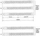
도 7는 MBSFN 서브프레임을 이용하여 백홀 전송을 수행하는 예를 나타낸다. 인-밴드 중계 모드에서 기지국-릴레이 링크(즉, 백홀 링크)는 릴레이-단말 링크(즉, 액세스 링크)와 동일한 주파수 대역에서 동작한다. 릴레이가 기지국으로부터 신호를 수신하면서 단말로 신호를 전송하거나 그 반대의 경우에서, 릴레이의 송신기와 수신기는 서로 간섭을 유발하므로 릴레이가 동시에 송신과 수신을 하는 것은 제한될 수 있다. 이를 위해, 백홀 링크와 액세스 링크는 TDM 방식으로 파티셔닝(partitioning) 된다. LTE-A는 릴레이 존에 존재하는 레거시 LTE 단말의 측정 동작을 지원하기 위해 MBSFN 서브프레임에서 백홀 링크를 설정한다(fake MBSFN 방법). 임의의 서브프레임이 MBSFN 서브프레임으로 시그널링 된 경우, 단말은 해당 서브프레임의 제어 영역(ctrl)만을 수신하므로 릴레이는 해당 서브프레임의 데이터 영역을 이용해 백홀 링크를 구성할 수 있다.FIG. 7 shows an example of performing a backhaul transmission using an MBSFN subframe. In the in-band relay mode, the base station-relay link (i.e., backhaul link) operates in the same frequency band as the relay-terminal link (i.e., access link). In a case where a relay transmits a signal to a terminal while receiving a signal from a base station and vice versa, the transmitter and the receiver of the relay cause interference with each other, so that transmission and reception of the relay at the same time may be restricted. To this end, the backhaul link and the access link are partitioned in a TDM manner. LTE-A establishes a backhaul link in the MBSFN subframe (fake MBSFN method) to support the measurement operation of the legacy LTE terminal in the relay zone. When an arbitrary subframe is signaled as an MBSFN subframe, the UE receives only the control region (ctrl) of the corresponding subframe, so that the relay can construct a backhaul link using the data region of the corresponding subframe.
상기 백홀 링크의 서브프레임은 현재 다음 표 1 및 표 2를 이용하여 그 구조가 결정될 수 있다. 보다 상세히 설명하면, 현재 LTE/LTE-A 시스템의 기지국은 다음 표 1의 제1 슬롯 설정 및 표 2의 제2 슬롯 설정의 조합으로 이루어지는 OFDM 심볼을 사용하는 서브프레임을 백홀 링크 서브프레임으로 사용한다.The structure of the sub-frame of the backhaul link can be currently determined using the following Tables 1 and 2. In more detail, the base station of the current LTE / LTE-A system uses a subframe using an OFDM symbol, which is a combination of the first slot setting in Table 1 and the second slot setting in Table 2, as a backhaul link subframe .


상기 표 1에서 DL_StartSymbol은 백홀 링크 서브프레임의 첫 번째 슬롯에서 사용될 수 있는 OFDM 심볼 중 첫 번째 OFDM 심볼을 지시하고, End symbol index는 첫 번째 슬롯에서 사용될 수 있는 OFDM 심볼 중 마지막 OFDM 심볼을 지시한다. 또한 표 2에서 Start symbol index는 백홀 링크 서브프레임의 두 번째 슬롯에서 사용될 수 있는 OFDM 심볼 중 첫 번째 OFDM 심볼을 지시하고, End symbol index는 첫 번째 슬롯에서 사용될 수 있는 OFDM 심볼 중 마지막 OFDM 심볼을 지시한다. 따라서, 백홀 링크 서브프레임은 표 1 및 표 2의 설정의 조합에 따라 구성될 수 있으며, 표 1 에서 설정 0과 표 2에서 설정 0은 동시에 사용되지 않는다.In Table 1, DL_StartSymbol indicates the first OFDM symbol among the OFDM symbols that can be used in the first slot of the backhaul link subframe, and the End symbol index indicates the last OFDM symbol among the OFDM symbols that can be used in the first slot. Also, in Table 2, the Start symbol index indicates the first OFDM symbol among OFDM symbols that can be used in the second slot of the backhaul link subframe, and the End symbol index indicates the last OFDM symbol among the OFDM symbols that can be used in the first slot. do. Therefore, the backhaul link subframe can be configured according to a combination of settings in Table 1 and Table 2, and setting 0 in Table 1 and setting 0 in Table 2 are not used at the same time.
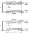
도 8은 상기 표 1 및 표 2로 결정되는 백홀 링크 서브프레임의 구성의 예시를 나타낸 도면이다. 도 8의 (a)는 표 1의 설정 0과 표 2의 설정 1의 조합, (b)는 표 1의 설정 1과 표 2의 설정 0의 조합, (c)는 표 1의 설정 1과 표 2의 설정 1의 조합, (d)는 표 1의 설정 2와 표 2의 설정 0의 조합, (e)는 표 1의 설정 2와 표 2의 설정 1의 조합을 나타낸다.8 is a diagram illustrating an example of a configuration of a backhaul link subframe determined in Tables 1 and 2. FIG. 8A shows a combination of setting 0 in Table 1 and setting 1 in Table 2, FIG. 8B shows a combination of setting 1 in Table 1 and setting 0 in Table 2, and FIG. (D) shows a combination of setting 2 in Table 1 and setting 0 in Table 2, and (e) shows a combination of setting 2 in Table 1 and setting 1 in Table 2.
한편, 상기 백홀 링크 서브프레임은 기지국에서 사용되는 서브프레임과 릴레이에서 사용되는 서브프레임의 경계(boundary)가 일치하는지 여부에 따라 사용될 수 있는 슬롯 설정의 조합이 결정되어 있고, 이는 도 9에 도시되어 있다. 도 9를 참조하면, 도 9의 (a), (b), (c)는 기지국과 릴레이의 서브프레임 경계가 일치하는 경우에 사용될 수 있는 슬롯 설정의 조합을 나타내며, (d), (e)는 기지국과 릴레이의 서브프레임 경계가 일치하지 않는 경우 사용될 수 있는 슬롯 설정의 조합을 나타낸다.On the other hand, in the backhaul link subframe, a combination of slot settings that can be used is determined depending on whether the subframes used in the base station and the subframes used in the relay coincide with each other, have. 9 (a), 9 (b) and 9 (c) show combinations of slot settings that can be used when the subframe boundaries of the base station and the relay coincide with each other, Represents a combination of slot settings that can be used when the subframe boundaries of the base station and the relay do not match.
상술한 바와 같이 결정되는 백홀 링크 서브프레임은 액세스 링크에 영향을 주지 않으면서 백홀 링크의 전송을 지원할 수 있다. 또한 소정 정도의 전파지연도 수용할 수 있다. 이에 대해 도 10을 참조하여 설명한다.The backhaul link subframe determined as described above can support the transmission of the backhaul link without affecting the access link. It is also possible to accommodate a certain degree of propagation delay. This will be described with reference to FIG.
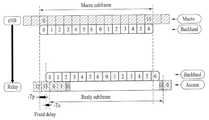
도 10은 기지국-릴레이간 하향링크 전송을 설명하기 위한 도면이다. 도 10에서 도시된 바와 같이 기지국과 릴레이의 서브프레임 경계는 일치되어 있으며, (a)는 전파지연이 없는 경우를, (b)는 소정 전파지연이 있는 경우를 나타낸다. 도 10에서 G1은 릴레이가 액세스 링크 전송에서 백홀 링크 수신으로 전환 시 필요한 가드 인터벌(Guard interval)을, G2는 릴레이가 백홀 링크 수신에서 액세스 링크 전송으로 전환 시 필요한 가드 인터벌을 나타낸다.10 is a diagram for explaining downlink transmission between a base station and a relay. As shown in FIG. 10, the subframe boundaries of the base station and the relay are coincident, (a) shows a case where there is no propagation delay, and (b) shows a case where there is a predetermined propagation delay. In FIG. 10, G1 represents a guard interval necessary for a relay to switch from an access link transmission to a backhaul link reception, and G2 represents a guard interval required when the relay switches from reception of a backhaul link to transmission of an access link.
도 10(a)를 참조하면, 대략 0.5 OFDM 심볼 정도의 전파지연이 있는 것을 알 수 있다. 이러한 경우 릴레이의 액세스 링크 전송에서 단말로 전송하는 PDCCH에 사용되는 OFDM 심볼(OFDM 심볼 인덱스 0, 1), 가드 인터벌(G1) 및 전파지연(Tp)를 고려하면 첫 번째 슬롯의 시작 OFDM 심볼 인덱스는 2가 된다. 또한 두 번째 슬롯의 마지막 OFDM 심볼 인덱스는 5가 된다. 따라서, 기지국은 첫 번째 슬롯 설정 1 및 두 번째 슬롯 설정 1에 해당하는 백홀 링크 서브프레임을 사용할 수 있다.Referring to FIG. 10 (a), it can be seen that there is a propagation delay of about 0.5 OFDM symbols. In this case, considering the OFDM symbols (
다만 상술한 바와 현재의 LTE/LTE-A 시스템에서의 백홀 링크 서브프레임은 대략 0.5 OFDM 심볼 정도의 시간에 상응하는 전파지연에만 대처할 수 있다. 즉, 도 10(b)에 도시된 바와 같이 전파지연값이 대략 1 OFDM 심볼 정도로 커지는 경우, 도 10(a)와 같은 백홀 링크 서브프레임을 사용할 경우 마지막 OFDM 심볼(인덱스 5)은 가드 인터벌(G2)와 겹치게 되어(즉, 릴레이의 백홀 링크 수신에서 액세스 링크 전송으로 전환 시 필요한 시간을 확보해 주지 못함) 릴레이의 액세스 링크 전송에 지장을 주게 된다.However, the above-described backhaul link subframes in the current LTE / LTE-A system can cope with only the propagation delay corresponding to a time of about 0.5 OFDM symbols. 10B, when the backhaul link subframe as shown in FIG. 10A is used, the last OFDM symbol (index 5) is divided into the guard interval G2 ) (I.e., failing to secure the time required for switching from the reception of the backhaul link of the relay to the transmission of the access link).
특히, 릴레이가 이동성을 갖게 되는 모바일 릴레이(Mobile Relay)의 경우에는 전파지연값이 수시로 변하게 되고, 이에 따라 백홀 링크 서브프레임의 구성을 액세스 링크에 영향을 주지 않도록 동적으로 설정할 필요가 있다. 이러한 경우 백홀 링크 서브프레임의 구성은 기지국과 릴레이 간 공유될 필요가 있다. 따라서, 이하 가변하는 전파지연값에 따라 백홀 링크 서브프레임을 어떻게 구성할 것인지와 전파지연값에 따라 달라지는 백홀 링크 서브프레임의 구조를 릴레이에게 어떻게 알려줄 것인지에 관한 실시예들이 개시된다. 이하의 실시예는 기지국과 릴레이의 관계를 위주로 설명되지만, 반드시 이에 한정되는 것은 아니며 기지국과 단말의 관계에서도 적용될 수 있음을 밝혀둔다.Particularly, in the case of a mobile relay in which the relay has mobility, the propagation delay value is changed from time to time, so that it is necessary to dynamically set the configuration of the backhaul link subframe so as not to affect the access link. In this case, the configuration of the backhaul link subframe needs to be shared between the base station and the relay. Accordingly, embodiments of how to configure the backhaul link subframe according to the following variable propagation delay value and how to inform the relay of the structure of the backhaul link subframe depending on the propagation delay value are disclosed. The following embodiments will be described focusing on the relationship between a base station and a relay, but the present invention is not limited thereto and can be applied to a relationship between a base station and a terminal.
실시예Example 1 One
본 발명의 제1 실시예는 기지국과 릴레이의 서브프레임 경계가 정렬된 경우 기지국-릴레이 하향링크에 있어서 백홀 링크 서브프레임에 관한 것이다. 설명의 편의를 위해 기지국-릴레이 하향링크에서 전파지연값의 변동에 따라 백홀 링크 서브프레임을 어떻게 구성할 것인지에 대해 설명한 후, 이 정보를 기지국과 릴레이가 공유하는 방법에 대해 설명한다.The first embodiment of the present invention relates to a backhaul link subframe in a base station-relay downlink when subframe boundaries of a base station and a relay are aligned. For convenience of description, a method of configuring the backhaul link subframe according to the variation of the propagation delay value in the base station-relay downlink will be described, and then a method of sharing the information between the base station and the relay will be described.
도 11 내지 도 13은 서브프레임 경계가 정렬된 경우 전파지연값이 증가함에 따른 백홀 하향링크 서브프레임의 구성을 나타내는 도면이다. 이하의 설명에서 릴레이의 액세스 링크 전송에서 단말로 전송하는 PDCCH에 사용되는 OFDM 심볼은 처음 두 심볼인 것을 전제로 한다.11 to 13 are views showing a configuration of a backhaul downlink subframe according to an increase in propagation delay value when subframe boundaries are aligned. In the following description, it is assumed that the OFDM symbol used for the PDCCH transmitted from the access link transmission of the relay to the UE is the first two symbols.
도 11(a)를 참조하면, 전파지연값이 가드 인터벌보다 작은 경우를 나타낸다. 도 11(a)에서 백홀 링크 서브프레임은 액세스 링크에 사용되는 2개의 OFDM 심볼 및 가드 인터벌을 고려하면 첫 번째 슬롯에서 인덱스 3의 OFDM 심볼을 시작 심볼로 가질 수 있다. 두 번째 슬롯에서 종료 심볼은 가드 인터벌을 고려하여 인덱스 5의 OFDM 심볼이 될 수 있다. 사용가능한 OFDM 심볼 수는 10개이다.Referring to Fig. 11 (a), the propagation delay value is smaller than the guard interval. In FIG. 11 (a), the backhaul link subframe may have an OFDM symbol of
도 11(b)는 도 11(a)보다 전파지연값이 다소 증가한 것을 나타낸다. 도시된 바와 같이 백홀 링크 서브프레임은 첫 번째 슬롯에서 시작 심볼로 인덱스 2의 OFDM 심볼을, 두 번째 슬롯에서 종료 심볼로 인덱스 5의 OFDM 심볼을 가질 수 있다. 사용 가능한 OFDM 심볼 수는 11개가 된다.Fig. 11 (b) shows that the propagation delay value is slightly increased as compared with Fig. 11 (a). As illustrated, the backhaul link subframe may have an OFDM symbol of
계속해서 도 12(a)는 하나의 OFDM 심볼에 상응하는 시간보다 조금 큰 전파지연값을 가지는 경우로서, 도시된 바와 같이 백홀 링크 서브프레임은 첫 번째 슬롯에서 시작 심볼로 인덱스 2의 OFDM 심볼을, 두 번째 슬롯에서 종료 심볼로 인덱스 4의 OFDM 심볼을 가질 수 있다. 도 11(b)의 경우와 비교해 전파지연값이 더 커져서 두 번째 슬롯에서 종료 심볼의 인덱스가 5에서 4로 변경된 것을 알 수 있다. 사용 가능한 OFDM 심볼 수는 10개가 된다.12 (a) shows a case where the propagation delay value is slightly larger than the time corresponding to one OFDM symbol. As shown in the figure, the backhaul link subframe includes OFDM symbols of
도 12(b)에서 백홀 링크 서브프레임은 첫 번째 슬롯에서 시작 심볼로 인덱스 1의 OFDM 심볼을, 두 번째 슬롯에서 종료 심볼로 인덱스 3의 OFDM 심볼을 가질 수 있다. 도 12(a)와 비교해 전파지연값이 조금 더 증가함에 따라 종료 심볼의 인덱스가 3으로 변경되었지만, 시작 심볼의 인덱스가 1로 변경되어 전체적으로 사용 가능한 OFDM 심볼 수는 10개를 유지한다.In FIG. 12B, the backhaul link subframe may have an OFDM symbol of
도 13(a)는 두 OFDM 심볼보다 조금 큰 전파지연값을 가지는 경우로서 백홀 링크 서브프레임은 첫 번째 슬롯에서 시작 심볼로 인덱스 1의 OFDM 심볼을, 두 번째 슬롯에서 종료 심볼로 인덱스 2의 OFDM 심볼을 가질 수 있다. 사용 가능한 OFDM 심볼 수는 10개이다.13A shows a case in which the backhaul link subframe has a propagation delay value slightly larger than that of two OFDM symbols. The backhaul link subframe includes an OFDM symbol of
상술한 바와 같이, 백홀 링크 서브프레임의 구성은 기지국이 전파지연값을 통해 동적으로 결정되며, 이 때 기존 LTE/LTE-A 시스템에서의 슬롯 설정(상술한 표 1 및 표 2)을 이용할 수도 있다. 다만, 전파지연값의 증가에 따른 시작 심볼 및 종료 심볼의 변경을 지원하기 위해 백홀 링크 서브프레임의 첫 번째 슬롯 설정을 나타내는 표 1은 다음 표 3으로, 두 번째 슬롯 설정을 나타내는 표 2는 다음 표 4와 같이 수정될 수 있다. 여기서 다음 표 3 및 표 4는 전파지연값으로 두 개의 OFDM 심볼 정도를 고려한 예시적인 것으로써, 전파지연값이 더 큰 경우 변경될 수 있다.As described above, the configuration of the backhaul link subframe is dynamically determined by the base station through the propagation delay value, and at this time, the slot setting in the existing LTE / LTE-A system (Table 1 and Table 2 described above) . Table 1, which shows the first slot setting of the backhaul link subframe, supports the change of the start symbol and the end symbol according to the increase of the propagation delay value, and Table 2, which shows the second slot setting, 4 can be modified as follows. Here, the following Tables 3 and 4 are exemplary considering the degree of two OFDM symbols as the propagation delay value, and can be changed when the propagation delay value is larger.


상기 표 3 및 표 4 이외에 추가적으로, 전파지연값과 첫 번째 슬롯 설정 및 두 번째 슬롯 설정의 대응 관계를 미리 설정하여 둘 수도 있다. 예를 들어, 다음 표 5와 같이 설정되어 있을 수 있다.In addition to the above Tables 3 and 4, a corresponding relation between the propagation delay value and the first slot setting and the second slot setting may be set in advance. For example, it may be set as shown in Table 5 below.

정리하면, 상기 도 11 내지 13에서 살펴본 바와 같이, 전파지연값의 증가는 백홀 링크 서브프레임 구조의 변화를 가져오고, 기지국은 전파지연값에 따라 동적으로 백홀 링크 서브프레임을 구성하여 사용할 수 있다. 다만, 이러한 경우 릴레이에서 백홀 링크 서브프레임의 정확한 복조를 위해 동적으로 변경된 서브프레임 구조를 알 필요가 있다.11 to 13, an increase in the propagation delay value causes a change in the structure of the backhaul link subframe, and the base station can dynamically construct the backhaul link subframe according to the propagation delay value. However, in this case, it is necessary to know the dynamically changed subframe structure for accurate demodulation of the backhaul link subframe in the relay.
이를 위해 릴레이는 전파지연값(또는 이에 상응하는 타이밍 변경 정보)을 수시로 보고하고, 기지국은 이 전파지연값에 따라 백홀 링크 서브프레임을 구성할 수 있다. 이 경우 기지국은 항상 릴레이가 보고한 전파지연값에 따라 백홀 링크 서브프레임을 구성하므로, 릴레이는 기지국으로부터 새롭게 구성된 백홀 링크 서브프레임의 구성에 관한 정보를 수신하지 않더라도 백홀 링크 서브프레임을 정확히 복조할 수 있다. 예를 들어, 도 12를 다시 참조하면, 릴레이는 전파지연값(Tp)를 기지국으로 보고하며, 기지국은 이에 따라 첫 번째 슬롯에서 시작 심볼 인덱스 0, 두 번째 슬롯에서 종료 심볼 인덱스 2를 갖는 백홀 링크 서브프레임을 통해 PDSCH, R-PDCCH등을 전송할 수 있다. 릴레이는 기지국이 자신이 보고한 전파지연값(Tp)를 이용해 백홀 링크 서브프레임을 구성한다는 것을 알고 있기 때문에 백홀 링크 서브프레임의 구조를 예측할 수 있다. 따라서 릴레이는 전파지연값만큼 지연된 시간(즉, 액세스 링크에서 PDCCH를 전송하기 시작한 시점으로부터 전파지연값(Tp)만큼 경과한 시간)부터 백홀 링크 서브프레임을 수신하며 그 시작 심볼이 인덱스 0임을 알고 복조할 수 있다.To this end, the relay reports the propagation delay value (or the corresponding timing change information) from time to time, and the base station can configure the backhaul link subframe according to the propagation delay value. In this case, since the base station always constructs the backhaul link subframe according to the propagation delay value reported by the relay, the relay can correctly demodulate the backhaul link subframe without receiving information on the configuration of the newly configured backhaul link subframe from the base station have. For example, referring back to FIG. 12, the relay reports the propagation delay value Tp to the base station, and thus the base station transmits a backhaul link having a
또는, 릴레이는 전파지연값을 수시로 보고하지만 기지국은 이를 추천값(recommended value)로 고려하는 방식으로 설정될 수도 있다. 다만, 이러한 경우에는 릴레이가 자신이 보고한 전파지연값에 따라 기지국이 백홀 링크 서브프레임을 구성하지 않을 수도 있기 때문에, 기지국으로부터 백홀 링크 서브프레임의 구조에 관한 정보를 수신하여야 한다. 이러한 백홀 링크 서브프레임의 구조에 관한 정보는 i) 백홀 링크 서브프레임의 첫 번째 슬롯 설정 정보 + 두 번째 슬롯 설정 정보, ii) 백홀 링크 서브프레임에서 사용되는 시작 OFDM 심볼 인덱스 + 백홀 링크 서브프레임에서 사용되는 총 OFDM 심볼 수, iii) 백홀 링크 서브프레임에서 사용되는 시작 OFDM 심볼 인덱스 + 마지막 OFDM 심볼 인덱스 등 다양한 방식으로 이루어질 수 있다.Alternatively, the relay may report the propagation delay value from time to time, but the base station may be set in a manner that considers this as a recommended value. However, in this case, since the base station may not configure the backhaul link subframe according to the propagation delay value reported by the relay, the base station should receive information on the structure of the backhaul link subframe from the base station. The information on the structure of this backhaul link subframe may be used for: i) first slot setup information of the backhaul link subframe + second slot setup information, ii) starting OFDM symbol index used in the backhaul link subframe + backhaul link subframe Iii) starting OFDM symbol index + last OFDM symbol index used in the backhaul link subframe, and so on.
한편, 기지국이 릴레이로부터 전파지연값을 보고 받지 않고 그 값을 추정하여 백홀 링크 서브프레임을 구성할 수도 있다. 이 경우에는 추정한 타이밍 정보를 RN에서 전송하고 그에 맞추어 백홀 링크 서브프레임을 구성하여 전송할 수 있다.On the other hand, the base station may construct the backhaul link subframe by estimating the value without reporting the propagation delay value from the relay. In this case, the estimated timing information may be transmitted in the RN, and a backhaul link subframe may be formed and transmitted.
상술한 방법 외에, 백홀 링크 서브프레임에 사용되는 OFDM 심볼 수를 작은 값으로 미리 설정하여 두고, 기지국이 시작 심볼 또는 마지막 심볼의 인덱스만 알려주도록 설정될 수도 있다. 이 방법은, 통상적으로 셀 크기 등을 고려할 때 전파지연값은 두개의 OFDM 심볼을 넘지 않으며, 앞서 도 11 내지 도 13에서 살펴본 바와 같이, 전파지연값이 두개의 OFDM 심볼을 넘지 않는 경우 백홀 링크 서브프레임에서 사용될 수 있는 총 OFDM 심볼 개수는 10 또는 11개임을 이용하는 것이다. 따라서 기지국과 릴레이 사이에 백홀 링크 서브프레임에 사용되는 OFDM 심볼 개수는 10개로 약속해 두고, 기지국은 전파지연값의 변동에 따라 변경되는 시작 OFDM 심볼의 인덱스만 알려주도록 설정할 수도 있다. 이러한 경우, 전파지연값이 더 커지는 경우를 대비하여, 지원 가능한 최대 전파지연값에 따라 사용 가능한 백홀 링크 서브프레임의 OFDM 심볼 개수의 최소값을 릴레이 능력(capability)에 포함시켜 둘 수도 있다.In addition to the above method, the number of OFDM symbols used for the backhaul link subframe may be preset to a small value, and the base station may be set to notify only the start symbol or the index of the last symbol. In this method, the propagation delay value does not exceed two OFDM symbols when the cell size and the like are taken into consideration. If the propagation delay value does not exceed two OFDM symbols as described above with reference to FIGS. 11 to 13, The total number of OFDM symbols that can be used in the frame is 10 or 11. Accordingly, the number of OFDM symbols used in the backhaul link subframe between the base station and the relay may be set to 10, and the base station may be configured to notify only the index of the starting OFDM symbol that changes according to the variation of the propagation delay value. In this case, the minimum value of the number of OFDM symbols of the available backhaul link subframe may be included in the relay capability according to the maximum supported propagation delay value, in case the propagation delay value becomes larger.
상술한 설명에서 릴레이의 전파지연값의 보고는 주기적으로 수행되거나, 이벤트 트리거(event trigger) 방식으로 수행될 수 있다. 예를 들어, 전파지연값의 참조값 및 변동의 임계값을 미리 설정하여 두고, 전파지연값이 참조값에 비해 임계값 이상으로 변화하는 경우에는 전파지연값을 기지국으로 보고할 수 있다. 또한, 전파지연값의 측정 및 보고 대신 현재 LTE/LTE-A 시스템에서의 타이밍 어드밴스(timing advance)에 기반해서 상술한 동작을 수행할 수도 있다.In the above description, the reporting of the propagation delay value of the relay may be performed periodically or in an event trigger manner. For example, the reference value of the propagation delay value and the threshold value of the variation may be set in advance, and the propagation delay value may be reported to the base station when the propagation delay value changes by more than the threshold value with respect to the reference value. Alternatively, instead of measuring and reporting the propagation delay value, the above operations may be performed based on the timing advance in the current LTE / LTE-A system.
실시예Example 2 2
본 발명의 제2 실시예는 기지국과 릴레이의 서브프레임 경계가 정렬되지 않은 경우 기지국-릴레이 하향링크에 있어서 백홀 링크 서브프레임에 관한 것이다.A second embodiment of the present invention relates to a backhaul link subframe in a base station-relay downlink when a subframe boundary between a base station and a relay is not aligned.
도 14는 서브프레임 경계가 정렬되지 않은 경우 백홀 하향링크 서브프레임의 구성을 나타내는 도면이다.FIG. 14 is a diagram illustrating a configuration of a backhaul downlink subframe when subframe boundaries are not aligned.
도 14를 참조하면, 실시예 1의 경우와 비교하여 기지국과 릴레이의 서브프레임 경계가 정렬되어 있지 않은 것에 연유한 차이값(도면에서는 To+Tp)를 더 고려하여 백홀 링크 서브프레임을 구성한다는 점에서만 차이가 있다. 따라서, 백홀 링크 서브프레임의 구성 및 이 정보를 릴레이와 공유하는 방법들은 실시예 1에 관한 설명으로 대체하기로 한다.Referring to FIG. 14, a backhaul link subframe is constructed by considering a difference value (To + Tp in the drawing) due to the fact that the subframe boundaries of the base station and the relay are not aligned as compared with the case of the first embodiment There is only difference. Therefore, the configuration of the backhaul link sub-frame and the methods of sharing this information with the relay will be replaced with the description related to the first embodiment.
실시예Example 3 3
본 발명의 제3 실시예는 기지국과 릴레이의 서브프레임 경계가 정렬되어 있는 경우 릴레이-기지국 상향링크에 있어서 백홀 링크 서브프레임에 관한 것이다.A third embodiment of the present invention relates to a backhaul link subframe in a relay-base station uplink when subframe boundaries of a base station and a relay are aligned.
도 15 내지 도 17은 서브프레임 경계가 정렬된 경우 상향링크에서 전파지연값이 증가함에 따른 백홀 링크 서브프레임의 구성을 나타내는 도면이다.FIGS. 15 to 17 are views showing a configuration of a backhaul link subframe according to an increase in propagation delay value in an uplink when subframe boundaries are aligned. FIG.
도 15를 참조하면, 전파지연값(Tp)으로 인해 백홀 링크 서브프레임의 첫 번째 OFDM 심볼을 사용하지 못하는 경우의 발생을 방지하기 위해, 액세스 링크의 단말들은 릴레이로 전송하는 서브프레임의 마지막 OFDM 심볼을 사용하지 않는다. 이는, 상향링크 사운딩 기준 신호(Sounding Reference Signal, SRS) 전송에 있어서, 다른 단말들로부터 PUSCH 전송과의 충돌을 피하기 위해 단말들이 마지막 OFDM 심볼을 사용하지 않는 것과 유사하다. 다만, 이러한 경우에도 전파지연값이 도 16과 같이 커진 경우 백홀 링크 서브프레임에서 사용 가능한 OFDM 심볼의 손실은 피할 수 없다.Referring to FIG. 15, in order to prevent occurrence of a case where the first OFDM symbol of the backhaul link subframe can not be used due to the propagation delay value Tp, the terminals of the access link transmit the last OFDM symbol Do not use. This is similar to that in the transmission of the uplink sounding reference signal (SRS), terminals do not use the last OFDM symbol to avoid collision with PUSCH transmission from other terminals. In this case, however, loss of usable OFDM symbols in the backhaul link subframe can not be avoided if the propagation delay value is large as shown in FIG.
도 16에는 전파지연값의 증가한 경우 백홀 링크 서브프레임 구성의 가능한 방법이 도시되어 있다. 도 16(a)에는 백홀 링크 서브프레임의 첫 번째 OFDM 심볼을 사용하지 않도록 설정한 경우를 나타내며, 도 16(b)는 액세스 링크에서 단말들이 마지막 OFDM 심볼에 추가적으로 한 심볼을 더 사용하지 못하도록 하는 경우를 나타낸다. 또한 도 17에는 도 16보다 전파지연값이 더 큰 경우로써, 도 16(a)에는 백홀 링크 서브프레임의 처음 두 개의 OFDM 심볼을 사용하지 않도록 설정한 경우를, 도 16(b)에는 액세스 링크의 단말들이 마지막 두 개의 OFDM 심볼을 사용하지 못하도록 하는 동시에 백홀 링크 서브프레임의 첫 번째 OFDM 심볼을 사용하지 않도록 설정한 경우를 나타낸다.Fig. 16 shows a possible method of backhaul link subframe construction when the propagation delay value is increased. FIG. 16A shows a case where the first OFDM symbol of the backhaul link subframe is not used. FIG. 16B shows a case where the terminals can not further use a symbol in addition to the last OFDM symbol in the access link . FIG. 16 shows a case where the first two OFDM symbols of the backhaul link subframe are not used. FIG. 16 (b) shows a case where the first access point The UEs are prevented from using the last two OFDM symbols and the first OFDM symbol of the backhaul link subframe is not used.
도 16(a) 및 도 17(a)의 경우는 액세스 링크에는 영향을 주지 않지만, 필수적으로 백홀 링크 서브프레임 구조의 변동을 가져온다. 따라서, 이러한 경우 앞서 설명된 실시예 1의 경우에서와 같이 전파지연값에 따라 백홀 링크 서브프레임의 구조를 동적으로 변경시킬 수 있고, 필요한 경우 변경된 백홀 링크 서브프레임에 관한 정보를 기지국으로 전송할 수 있다. 이와 같이 설정함으로써 기지국은 릴레이로부터 전송된 백홀 링크 서브프레임을 정확히 복조 할 수 있다. 이에 대한 자세한 설명은 실시예 1에 대한 설명과 중첩되므로, 생략하기로 한다.16 (a) and 17 (a) do not affect the access link, but necessarily bring about variations in the backhaul link subframe structure. Accordingly, in this case, the structure of the backhaul link subframe can be changed dynamically according to the propagation delay value as in the case of the first embodiment described above, and information on the changed backhaul link subframe can be transmitted to the base station if necessary . By setting in this manner, the base station can accurately demodulate the backhaul link subframe transmitted from the relay. A detailed description thereof will be omitted because it overlaps with the description of the first embodiment.
실시예Example 4 4
본 발명의 제4 실시예는 기지국과 릴레이의 서브프레임 경계가 정렬되어 있지 않은 경우, 릴레이-기지국 상향링크에 있어서 백홀 링크 서브프레임에 관한 것이다.A fourth embodiment of the present invention relates to a backhaul link subframe in a relay-base station uplink when the subframe boundaries of the base station and the relay are not aligned.
도 18에는 서브프레임 경계가 정렬되지 않은 경우 전파지연값을 고려한 백홀 상향링크 서브프레임의 구성을 나타내는 도면이다. 도 18의 경우에도 서브프레임 경계의 차이로 인한 시간값만 더 고려한다는 점을 제외하고는 실시예 3의 경우와 유사하게 이해될 수 있다.FIG. 18 is a diagram illustrating a configuration of a backhaul uplink subframe in which a propagation delay value is considered when subframe boundaries are not aligned. In the case of FIG. 18, it can be understood similarly to the case of the third embodiment, except that only the time value due to the difference of the subframe boundaries is further considered.
도 19는 본 발명에 따른 기지국 장치 및 단말 장치의 구성을 도시한 도면이다.19 is a diagram showing a configuration of a base station apparatus and a terminal apparatus according to the present invention.
도 19를 참조하여 본 발명에 따른 기지국 장치(1910)는, 수신모듈(1911), 전송모듈(1912), 프로세서(1913), 메모리(1914) 및 복수개의 안테나(1915)를 포함할 수 있다. 복수개의 안테나(1915)는 MIMO 송수신을 지원하는 기지국 장치를 의미한다. 수신모듈(1911)은 단말로부터의 상향링크 상의 각종 신호, 데이터 및 정보를 수신할 수 있다. 전송모듈(1912)은 단말로의 하향링크 상의 각종 신호, 데이터 및 정보를 전송할 수 있다. 프로세서(1913)는 기지국 장치(1910) 전반의 동작을 제어할 수 있다.19, a
본 발명의 일 실시예에 따른 기지국 장치(1910)는 상향링크 다중 안테나 전송에 대한 제어 정보를 전송하도록 구성될 수 있다. 기지국 장치의 프로세서(1913)는, 전파지연값에 따라 제1 슬롯 설정 및 제2 슬롯 설정을 결정하고, 상기 제1 슬롯 설정 및 제2 슬롯 설정으로 결정되는 구조의 서브프레임을 통해 상기 신호를 전송할 수 있다. 여기서 상기 제1 슬롯 설정 및 제2 슬롯 설정은 각각 상기 전파지연값을 고려하여 결정되는 시작심볼 및 종료심볼을 포함할 수 있다.The
기지국 장치(1910)의 프로세서(1913)는 그 외에도 기지국 장치(1910)가 수신한 정보, 외부로 전송할 정보 등을 연산 처리하는 기능을 수행하며, 메모리(1914)는 연산 처리된 정보 등을 소정시간 동안 저장할 수 있으며, 버퍼(미도시) 등의 구성요소로 대체될 수 있다.The
계속해서 도 19를 참조하면 본 발명에 따른 단말 장치(1920)는, 수신모듈(1921), 전송모듈(1922), 프로세서(1923), 메모리(1924) 및 복수개의 안테나(1925)를 포함할 수 있다. 복수개의 안테나(1925)는 MIMO 송수신을 지원하는 단말 장치를 의미한다. 수신모듈(1921)은 기지국으로부터의 하향링크 상의 각종 신호, 데이터 및 정보를 수신할 수 있다. 전송모듈(1922)은 기지국으로의 상향링크 상의 각종 신호, 데이터 및 정보를 전송할 수 있다. 프로세서(1923)는 단말 장치(1920) 전반의 동작을 제어할 수 있다.19, a terminal apparatus 1920 according to the present invention may include a
본 발명의 일 실시예에 따른 단말 장치(1920)는 상향링크 다중 안테나 전송을 수행하도록 구성될 수 있다. 단말 장치의 프로세서(1923)는, 전파지연값에 따라 결정된 제1 슬롯 설정 및 제2 슬롯 설정에 해당하는 구조의 서브프레임을 통해 상기 신호를 수신할 수 있다. 여기서, 상기 제1 슬롯 설정 및 제2 슬롯 설정은 각각 상기 전파지연값을 고려하여 결정되는 시작심볼 및 종료심볼을 포함할 수 있다.The terminal apparatus 1920 according to an embodiment of the present invention may be configured to perform uplink multi-antenna transmission. The
단말 장치(1920)의 프로세서(1923)는 그 외에도 단말 장치(1920)가 수신한 정보, 외부로 전송할 정보 등을 연산 처리하는 기능을 수행하며, 메모리(1924)는 연산 처리된 정보 등을 소정시간 동안 저장할 수 있으며, 버퍼(미도시) 등의 구성요소로 대체될 수 있다.The
위와 같은 기지국 장치 및 단말 장치의 구체적인 구성은, 전술한 본 발명의 다양한 실시예에서 설명한 사항들이 독립적으로 적용되거나 또는 2 이상의 실시예가 동시에 적용되도록 구현될 수 있으며, 중복되는 내용은 명확성을 위하여 설명을 생략한다.The specific configuration of the base station apparatus and the terminal apparatus may be implemented such that the above-described embodiments of the present invention are applied independently or two or more embodiments may be simultaneously applied. For the sake of clarity, It is omitted.
또한, 도 19에 대한 설명에 있어서 기지국 장치(1910)에 대한 설명은 하향링크 전송 주체 또는 상향링크 수신 주체로서의 중계기 장치에 대해서도 동일하게 적용될 수 있고, 단말 장치(1920)에 대한 설명은 하향링크 수신 주체 또는 상향링크 전송 주체로서의 중계기 장치에 대해서도 동일하게 적용될 수 있다.19, the description of the
상술한 본 발명의 실시예들은 다양한 수단을 통해 구현될 수 있다. 예를 들어, 본 발명의 실시예들은 하드웨어, 펌웨어(firmware), 소프트웨어 또는 그것들의 결합 등에 의해 구현될 수 있다.The above-described embodiments of the present invention can be implemented by various means. For example, embodiments of the present invention may be implemented by hardware, firmware, software, or a combination thereof.
하드웨어에 의한 구현의 경우, 본 발명의 실시예들에 따른 방법은 하나 또는 그 이상의 ASICs(Application Specific Integrated Circuits), DSPs(Digital Signal Processors), DSPDs(Digital Signal Processing Devices), PLDs(Programmable Logic Devices), FPGAs(Field Programmable Gate Arrays), 프로세서, 컨트롤러, 마이크로 컨트롤러, 마이크로 프로세서 등에 의해 구현될 수 있다.In the case of hardware implementation, the method according to embodiments of the present invention may be implemented in one or more Application Specific Integrated Circuits (ASICs), Digital Signal Processors (DSPs), Digital Signal Processing Devices (DSPDs), Programmable Logic Devices (PLDs) , FPGAs (Field Programmable Gate Arrays), processors, controllers, microcontrollers, microprocessors, and the like.
펌웨어나 소프트웨어에 의한 구현의 경우, 본 발명의 실시예들에 따른 방법은 이상에서 설명된 기능 또는 동작들을 수행하는 모듈, 절차 또는 함수 등의 형태로 구현될 수 있다. 소프트웨어 코드는 메모리 유닛에 저장되어 프로세서에 의해 구동될 수 있다. 상기 메모리 유닛은 상기 프로세서 내부 또는 외부에 위치하여, 이미 공지된 다양한 수단에 의해 상기 프로세서와 데이터를 주고 받을 수 있다.In the case of an implementation by firmware or software, the method according to embodiments of the present invention may be implemented in the form of a module, a procedure or a function for performing the functions or operations described above. The software code can be stored in a memory unit and driven by the processor. The memory unit may be located inside or outside the processor, and may exchange data with the processor by various well-known means.
상술한 바와 같이 개시된 본 발명의 바람직한 실시예들에 대한 상세한 설명은 당업자가 본 발명을 구현하고 실시할 수 있도록 제공되었다. 상기에서는 본 발명의 바람직한 실시예들을 참조하여 설명하였지만, 해당 기술 분야의 숙련된 당업자는 본 발명의 영역으로부터 벗어나지 않는 범위 내에서 본 발명을 다양하게 수정 및 변경시킬 수 있음을 이해할 수 있을 것이다. 예를 들어, 당업자는 상술한 실시예들에 기재된 각 구성을 서로 조합하는 방식으로 이용할 수 있다. 따라서, 본 발명은 여기에 나타난 실시형태들에 제한되려는 것이 아니라, 여기서 개시된 원리들 및 신규한 특징들과 일치하는 최광의 범위를 부여하려는 것이다.DETAILED DESCRIPTION OF THE PREFERRED EMBODIMENTS The foregoing description of the preferred embodiments of the invention disclosed herein has been presented to enable any person skilled in the art to make and use the present invention. While the present invention has been particularly shown and described with reference to preferred embodiments thereof, it will be understood by those skilled in the art that various changes and modifications may be made therein without departing from the spirit and scope of the invention as defined by the appended claims. For example, those skilled in the art can utilize each of the configurations described in the above-described embodiments in a manner of mutually combining them. Accordingly, the present invention is not intended to be limited to the embodiments shown herein but is to be accorded the widest scope consistent with the principles and novel features disclosed herein.
본 발명은 본 발명의 정신 및 필수적 특징을 벗어나지 않는 범위에서 다른 특정한 형태로 구체화될 수 있다. 따라서, 상기의 상세한 설명은 모든 면에서 제한적으로 해석되어서는 아니 되고 예시적인 것으로 고려되어야 한다. 본 발명의 범위는 첨부된 청구항의 합리적 해석에 의해 결정되어야 하고, 본 발명의 등가적 범위 내에서의 모든 변경은 본 발명의 범위에 포함된다. 본 발명은 여기에 나타난 실시형태들에 제한되려는 것이 아니라, 여기서 개시된 원리들 및 신규한 특징들과 일치하는 최광의 범위를 부여하려는 것이다. 또한, 특허청구범위에서 명시적인 인용 관계가 있지 않은 청구항들을 결합하여 실시예를 구성하거나 출원 후의 보정에 의해 새로운 청구항으로 포함할 수 있다.The present invention may be embodied in other specific forms without departing from the spirit or essential characteristics thereof. Accordingly, the above description should not be construed in a limiting sense in all respects and should be considered illustrative. The scope of the present invention should be determined by rational interpretation of the appended claims, and all changes within the scope of equivalents of the present invention are included in the scope of the present invention. The present invention is not intended to be limited to the embodiments shown herein but is to be accorded the widest scope consistent with the principles and novel features disclosed herein. In addition, claims that do not have an explicit citation in the claims may be combined to form an embodiment or be included in a new claim by amendment after the filing.
상술한 설명에서는 본 발명을 3GPP LTE 계열 이동 통신 시스템에 적용되는 형태를 중심으로 설명하였으나, 본 발명은 다양한 이동통신 시스템에 동일 또는 균등한 원리로 이용될 수 있다.In the above description, the present invention is applied to a 3GPP LTE mobile communication system. However, the present invention can be applied to various mobile communication systems on the same or equal basis.
Claims (15)
Translated fromKorean상기 제1 노드 및 제2 노드 사이의 전파지연값에 따라 제1 슬롯 설정 및 제2 슬롯 설정을 결정하는 단계; 및
상기 제1 슬롯 설정 및 제2 슬롯 설정으로 결정되는 구조의 서브프레임을 통해 상기 신호를 전송하는 단계를 포함하며,
상기 제1 슬롯 설정 및 제2 슬롯 설정은 각각 상기 전파지연값을 고려하여 결정되는 시작심볼 및 종료심볼을 포함하는, 신호 전송방법.A method for a first node to transmit a signal to a second node in a mobile communication system,
Determining a first slot setting and a second slot setting according to a propagation delay value between the first node and the second node; And
And transmitting the signal through a subframe of a structure determined by the first slot setting and the second slot setting,
Wherein the first slot setting and the second slot setting each comprise a start symbol and an end symbol determined in consideration of the propagation delay value.
상기 제1 노드는 기지국이며 상기 제2 노드는 모바일 릴레이 노드인, 신호 전송방법.The method according to claim 1,
Wherein the first node is a base station and the second node is a mobile relay node.
상기 제1 노드와 상기 제2 노드의 서브프레임 경계가 정렬되어 있는 경우,
상기 제1 슬롯 설정의 시작심볼은, 상기 전파지연값, 가드 인터벌 및 상기 제2 노드로부터 단말로 전송되는 제어정보가 차지하는 심볼 개수를 사용하여 결정되며,
상기 제2 슬롯 설정의 종료심볼은, 상기 전파지연값 및 가드 인터벌을 사용하여 결정되는, 신호 전송방법.3. The method of claim 2,
When the subframe boundaries of the first node and the second node are aligned,
The start symbol of the first slot setting is determined using the propagation delay value, the guard interval, and the number of symbols occupied by the control information transmitted from the second node to the terminal,
And wherein the end symbol of the second slot setup is determined using the propagation delay value and the guard interval.
상기 제1 노드와 상기 제2 노드의 서브프레임 경계가 정렬되어 있지 않은 경우,
상기 제1 슬롯 설정의 시작심볼은, 상기 전파지연값, 가드 인터벌, 상기 제2 노드로부터 단말로 전송되는 제어정보가 차지하는 심볼 개수 및 상기 제1 노드와 상기 제2 노드의 서브프레임 경계의 차이값을 사용하여 결정되며,
상기 제2 슬롯 설정의 종료심볼은, 상기 전파지연값, 가드 인터벌 및 상기 제1 노드와 상기 제2 노드의 서브프레임 경계의 차이값을 사용하여 결정되는, 신호 전송방법.3. The method of claim 2,
If the subframe boundaries of the first node and the second node are not aligned,
Wherein the start symbol of the first slot configuration includes at least one of a propagation delay value, a guard interval, a symbol number occupied by control information transmitted from the second node to the terminal, and a difference value between the first node and a subframe boundary of the second node , ≪ / RTI >
Wherein the end symbol of the second slot setup is determined using the propagation delay value, the guard interval, and a difference value between subframe boundaries of the first node and the second node.
상기 결정된 제1 슬롯 설정 및 제2 슬롯 설정을 제2 노드로 전송하는 단계;
를 더 포함하는, 신호 전송방법.The method according to claim 1,
Transmitting the determined first slot configuration and second slot configuration to a second node;
≪ / RTI >
상기 전파지연값은 상기 제2노드로부터 수신된 것인, 신호 전송방법.The method according to claim 1,
Wherein the propagation delay value is received from the second node.
상기 전파지연값은 상기 제1 노드가 추정한 값인, 신호 전송방법.The method according to claim 1,
Wherein the propagation delay value is a value estimated by the first node.
상기 제1 노드 및 제2 노드 사이의 전파지연값에 따라 결정된 제1 슬롯 설정 및 제2 슬롯 설정에 해당하는 구조의 서브프레임을 통해 상기 신호를 수신하는 단계를 포함하며,
상기 제1 슬롯 설정 및 제2 슬롯 설정은 각각 상기 전파지연값을 고려하여 결정되는 시작심볼 및 종료심볼을 포함하는, 신호 수신방법.A method for a second node in a mobile communication system to receive a signal from a first node,
Receiving the signal through a subframe of a structure corresponding to a first slot setting and a second slot setting determined according to a propagation delay value between the first node and a second node,
Wherein the first slot setting and the second slot setting each comprise a start symbol and an end symbol determined in consideration of the propagation delay value.
상기 제1 노드는 기지국이며 상기 제2 노드는 모바일 릴레이 노드인, 신호 수신방법.9. The method of claim 8,
Wherein the first node is a base station and the second node is a mobile relay node.
상기 제1 노드와 상기 제2 노드의 서브프레임 경계가 정렬되어 있는 경우,
상기 제1 슬롯 설정의 시작심볼은, 상기 전파지연값, 가드 인터벌 및 상기 제2 노드로부터 단말로 전송되는 제어정보가 차지하는 심볼 개수를 사용하여 결정되며,
상기 제2 슬롯 설정의 종료심볼은, 상기 전파지연값 및 가드 인터벌을 사용하여 결정되는, 신호 수신방법.10. The method of claim 9,
When the subframe boundaries of the first node and the second node are aligned,
The start symbol of the first slot setting is determined using the propagation delay value, the guard interval, and the number of symbols occupied by the control information transmitted from the second node to the terminal,
Wherein the end symbol of the second slot setup is determined using the propagation delay value and the guard interval.
상기 제1 노드와 상기 제2 노드의 서브프레임 경계가 정렬되어 있지 않은 경우,
상기 제1 슬롯 설정의 시작심볼은, 상기 전파지연값, 가드 인터벌, 상기 제2 노드로부터 단말로 전송되는 제어정보가 차지하는 심볼 개수 및 상기 제1 노드와 상기 제2 노드의 서브프레임 경계의 차이값을 사용하여 결정되며,
상기 제2 슬롯 설정의 종료심볼은, 상기 전파지연값, 가드 인터벌 및 상기 제1 노드와 상기 제2 노드의 서브프레임 경계의 차이값을 사용하여 결정되는, 신호 수신방법.10. The method of claim 9,
If the subframe boundaries of the first node and the second node are not aligned,
Wherein the start symbol of the first slot configuration includes at least one of a propagation delay value, a guard interval, a symbol number occupied by control information transmitted from the second node to the terminal, and a difference value between the first node and a subframe boundary of the second node , ≪ / RTI >
Wherein the end symbol of the second slot setup is determined using the propagation delay value, the guard interval and the difference value between the first node and the subframe boundary of the second node.
상기 결정된 제1 슬롯 설정 및 제2 슬롯 설정을 제2 노드로 전송하는 단계;
를 더 포함하는, 신호 수신방법.The method according to claim 1,
Transmitting the determined first slot configuration and second slot configuration to a second node;
≪ / RTI >
상기 전파지연값은 상기 제2 노드가 전송한 것인, 신호 수신방법.The method according to claim 1,
Wherein the propagation delay value is transmitted by the second node.
송신모듈; 및
상기 송신모듈을 포함하는 상기 장치를 제어하는 프로세서를 포함하고,
상기 프로세서는, 상기 장치인 제1 노드 및 제2 노드 사이의 전파지연값에 따라 제1 슬롯 설정 및 제2 슬롯 설정을 결정하고, 상기 제1 슬롯 설정 및 제2 슬롯 설정으로 결정되는 구조의 서브프레임을 통해 상기 신호를 전송하며, 상기 제1 슬롯 설정 및 제2 슬롯 설정은 각각 상기 전파지연값을 고려하여 결정되는 시작심볼 및 종료심볼을 포함하는, 장치.An apparatus for transmitting a signal in a mobile communication system,
Transmitting module; And
And a processor for controlling the device including the transmitting module,
Wherein the processor determines a first slot setting and a second slot setting according to a propagation delay value between the first node and the second node which are the apparatuses and determines a first slot setting and a second slot setting, Frame, the first slot setting and the second slot setting each including a start symbol and an end symbol determined in consideration of the propagation delay value.
수신모듈; 및
상기 수신모듈을 포함하는 상기 장치를 제어하는 프로세서를 포함하고,
상기 프로세서는, 제1 노드 및 상기 장치인 제2 노드 사이의 전파지연값에 따라 결정된 제1 슬롯 설정 및 제2 슬롯 설정에 해당하는 구조의 서브프레임을 통해 상기 신호를 수신하며, 상기 제1 슬롯 설정 및 제2 슬롯 설정은 각각 상기 전파지연값을 고려하여 결정되는 시작심볼 및 종료심볼을 포함하는, 장치.An apparatus for receiving a signal in a mobile communication system,
Receiving module; And
And a processor for controlling the device including the receiving module,
Wherein the processor receives the signal through a subframe of a structure corresponding to a first slot setting and a second slot setting determined according to a propagation delay value between a first node and a second node that is a device, Wherein the setting and the second slot setting each comprise a start symbol and an end symbol determined in consideration of the propagation delay value.
Applications Claiming Priority (3)
| Application Number | Priority Date | Filing Date | Title |
|---|---|---|---|
| US201161467384P | 2011-03-25 | 2011-03-25 | |
| US61/467,384 | 2011-03-25 | ||
| PCT/KR2012/002149WO2012134123A2 (en) | 2011-03-25 | 2012-03-23 | Backhaul link subframe structure in mobile communication system and method for transmitting information thereof |
Publications (2)
| Publication Number | Publication Date |
|---|---|
| KR20140024341Atrue KR20140024341A (en) | 2014-02-28 |
| KR101973465B1 KR101973465B1 (en) | 2019-04-29 |
Family
ID=46932087
Family Applications (1)
| Application Number | Title | Priority Date | Filing Date |
|---|---|---|---|
| KR1020137028011AExpired - Fee RelatedKR101973465B1 (en) | 2011-03-25 | 2012-03-23 | Backhaul link subframe structure in mobile communication system and method for transmitting information thereof |
Country Status (4)
| Country | Link |
|---|---|
| US (1) | US9184893B2 (en) |
| EP (1) | EP2690799A4 (en) |
| KR (1) | KR101973465B1 (en) |
| WO (1) | WO2012134123A2 (en) |
Families Citing this family (9)
| Publication number | Priority date | Publication date | Assignee | Title |
|---|---|---|---|---|
| WO2014182339A1 (en)* | 2013-05-09 | 2014-11-13 | Intel IP Corporation | Small data communications |
| US9572106B2 (en)* | 2014-10-31 | 2017-02-14 | Qualcomm Incorporated | Dynamic bandwidth switching for reducing power consumption in wireless communication devices |
| CN109314674B (en)* | 2016-04-20 | 2022-09-09 | 瑞典爱立信有限公司 | Delaying transmission depending on transmission type and UE processing capability |
| US11012204B2 (en)* | 2016-06-08 | 2021-05-18 | Lg Electronics Inc. | Communication method of using full duplex in NR |
| CN108076515B (en)* | 2016-11-11 | 2023-09-12 | 中兴通讯股份有限公司 | Method and device for transmitting small time slot |
| EP4149041A1 (en)* | 2017-05-02 | 2023-03-15 | Ntt Docomo, Inc. | User terminal and radio communication method |
| CA3092433C (en)* | 2018-03-29 | 2022-04-19 | Mitsubishi Electric Corporation | Relay station, control station, and satellite communication system |
| CN110475329B (en)* | 2018-05-11 | 2020-11-06 | 维沃移动通信有限公司 | Wireless communication method, device and network equipment |
| US11277854B2 (en)* | 2019-01-22 | 2022-03-15 | T-Mobile Usa, Inc. | Systems and methods to enhance spectrum efficiency and to reduce latency by using dynamic guard time selection in wireless systems |
Citations (1)
| Publication number | Priority date | Publication date | Assignee | Title |
|---|---|---|---|---|
| KR20100093503A (en)* | 2009-02-16 | 2010-08-25 | 엘지전자 주식회사 | Method and apparatus of transmitting or receiving signal for relay station in wireless communication system |
Family Cites Families (12)
| Publication number | Priority date | Publication date | Assignee | Title |
|---|---|---|---|---|
| KR101465151B1 (en) | 2008-09-19 | 2014-11-25 | 노키아 솔루션스 앤드 네트웍스 오와이 | Network element and method of operating a network element |
| EP2398161A4 (en)* | 2009-02-16 | 2017-05-10 | LG Electronics Inc. | Method and apparatus for transmitting and receiving signal from relay station in radio communication system |
| EP2400674A4 (en)* | 2009-02-18 | 2017-03-22 | LG Electronics Inc. | Signal transmitting/receiving method for a relay node, and relay node using the method |
| WO2010095883A2 (en)* | 2009-02-19 | 2010-08-26 | 엘지전자 주식회사 | Method and apparatus for communication between a relay node and user equipment in a wireless communication system |
| KR101719995B1 (en)* | 2009-02-20 | 2017-03-27 | 엘지전자 주식회사 | Method for allocating reference signal of backhaul in relay communications system,and method and apparatus for transmitting and receiving data thereof |
| WO2010107234A2 (en)* | 2009-03-17 | 2010-09-23 | 한국전자통신연구원 | Data transmission method for wireless communication system involving relay |
| KR101295584B1 (en)* | 2009-04-09 | 2013-09-03 | 엘지전자 주식회사 | Signal transmission method and apparatus in a relay communication system |
| KR101584820B1 (en)* | 2009-04-15 | 2016-01-13 | 엘지전자 주식회사 | Method and apparatus for transmitting signal performed by relay station in wireless communication system |
| KR101643025B1 (en)* | 2009-08-12 | 2016-07-27 | 엘지전자 주식회사 | Relay station and method of relay station transmitting backhaul uplink signal |
| US8576755B2 (en)* | 2010-01-11 | 2013-11-05 | Qualcomm Incorporated | Apparatus and method for relay transition time |
| US9281889B2 (en)* | 2010-02-16 | 2016-03-08 | Lg Electronics Inc. | Relay node apparatus for transmitting and receiving signal according to link operation mode in wireless communication system and method thereof |
| US9356680B2 (en)* | 2010-03-11 | 2016-05-31 | Lg Electronics Inc. | Method of transceiving signal at relay node in wireless communication system and apparatus thereof |
- 2012
- 2012-03-23USUS14/007,592patent/US9184893B2/ennot_activeExpired - Fee Related
- 2012-03-23KRKR1020137028011Apatent/KR101973465B1/ennot_activeExpired - Fee Related
- 2012-03-23WOPCT/KR2012/002149patent/WO2012134123A2/enactiveApplication Filing
- 2012-03-23EPEP12765677.5Apatent/EP2690799A4/ennot_activeWithdrawn
Patent Citations (1)
| Publication number | Priority date | Publication date | Assignee | Title |
|---|---|---|---|---|
| KR20100093503A (en)* | 2009-02-16 | 2010-08-25 | 엘지전자 주식회사 | Method and apparatus of transmitting or receiving signal for relay station in wireless communication system |
Non-Patent Citations (1)
| Title |
|---|
| LG Electronics Inc., "Further Comments on DL/UL Timing Alternatives," 3GPP DRAFT, R1-101363(2010.02.26)** |
Also Published As
| Publication number | Publication date |
|---|---|
| KR101973465B1 (en) | 2019-04-29 |
| US9184893B2 (en) | 2015-11-10 |
| US20140016541A1 (en) | 2014-01-16 |
| EP2690799A2 (en) | 2014-01-29 |
| WO2012134123A2 (en) | 2012-10-04 |
| WO2012134123A3 (en) | 2013-01-03 |
| EP2690799A4 (en) | 2014-10-08 |
Similar Documents
| Publication | Publication Date | Title |
|---|---|---|
| KR101973465B1 (en) | Backhaul link subframe structure in mobile communication system and method for transmitting information thereof | |
| US9621314B2 (en) | Signal transmission method using MBSFN subframe in radio communication system | |
| US10862662B2 (en) | Method and apparatus for supporting mechanisms for flexible duplex operations at symbol level in wireless communication system | |
| KR101719995B1 (en) | Method for allocating reference signal of backhaul in relay communications system,and method and apparatus for transmitting and receiving data thereof | |
| KR101781854B1 (en) | Method and apparatus of transmitting sounding reference signal | |
| KR101227740B1 (en) | Method and device for wireless subframe resource allocation | |
| JP5727559B2 (en) | Method of operating repeater in wireless communication system | |
| JP5544416B2 (en) | Signal transmission method and apparatus in relay communication system | |
| CN102113398B (en) | Resource allocation method for backhaul link and access link in wireless communication system including relay | |
| CN113196859A (en) | Category 2 Listen Before Talk (LBT) options for unlicensed new radios (NR-U) | |
| KR101785659B1 (en) | Method and apparatus for performing communication in relay system | |
| WO2014112802A1 (en) | Method for performing communication between terminals and apparatus therefor | |
| KR101887064B1 (en) | Method for receiving downlink signal and method for transmitting same, user equipment, and base station | |
| KR20160114066A (en) | Method and apparatus for device-to-device terminal for tranceiving signal in wireless communication system | |
| US20130034030A1 (en) | Method and apparatus for configuring frame in wireless communication system including relay station | |
| WO2015126028A1 (en) | Method for transreceiving signals using user-specific flexible tdd technology in wireless communication system and device for same | |
| KR20160009534A (en) | Method and apparatus for transmitting/receiving signal related to device-todevice communication in wireless communication system | |
| WO2015137773A1 (en) | Method and apparatus for device-to-device user equipment to transmit signal in wireless communication system | |
| US12302265B2 (en) | User apparatus, base station, and communication system | |
| KR101698604B1 (en) | Method and appartus for transmitting frame in a wireless system including relay station | |
| US9225394B2 (en) | Method and apparatus for receiving a signal from a base station having a plurality of antennas | |
| KR20170052456A (en) | Methods for signal transmission and reception in a wireless communication system over high frequency bands and apparatuses thereof | |
| KR20140037693A (en) | Communication method, method for allocating wireless frame structure and apparatus for setting wireless frame | |
| KR20110031111A (en) | Method and apparatus for setting a frame in a wireless communication system including a relay station |
Legal Events
| Date | Code | Title | Description |
|---|---|---|---|
| PA0105 | International application | St.27 status event code:A-0-1-A10-A15-nap-PA0105 | |
| PG1501 | Laying open of application | St.27 status event code:A-1-1-Q10-Q12-nap-PG1501 | |
| R17-X000 | Change to representative recorded | St.27 status event code:A-3-3-R10-R17-oth-X000 | |
| PN2301 | Change of applicant | St.27 status event code:A-3-3-R10-R13-asn-PN2301 St.27 status event code:A-3-3-R10-R11-asn-PN2301 | |
| A201 | Request for examination | ||
| E13-X000 | Pre-grant limitation requested | St.27 status event code:A-2-3-E10-E13-lim-X000 | |
| P11-X000 | Amendment of application requested | St.27 status event code:A-2-2-P10-P11-nap-X000 | |
| P13-X000 | Application amended | St.27 status event code:A-2-2-P10-P13-nap-X000 | |
| PA0201 | Request for examination | St.27 status event code:A-1-2-D10-D11-exm-PA0201 | |
| D13-X000 | Search requested | St.27 status event code:A-1-2-D10-D13-srh-X000 | |
| D14-X000 | Search report completed | St.27 status event code:A-1-2-D10-D14-srh-X000 | |
| E902 | Notification of reason for refusal | ||
| PE0902 | Notice of grounds for rejection | St.27 status event code:A-1-2-D10-D21-exm-PE0902 | |
| T11-X000 | Administrative time limit extension requested | St.27 status event code:U-3-3-T10-T11-oth-X000 | |
| P11-X000 | Amendment of application requested | St.27 status event code:A-2-2-P10-P11-nap-X000 | |
| P13-X000 | Application amended | St.27 status event code:A-2-2-P10-P13-nap-X000 | |
| E701 | Decision to grant or registration of patent right | ||
| PE0701 | Decision of registration | St.27 status event code:A-1-2-D10-D22-exm-PE0701 | |
| GRNT | Written decision to grant | ||
| PR0701 | Registration of establishment | St.27 status event code:A-2-4-F10-F11-exm-PR0701 | |
| PR1002 | Payment of registration fee | St.27 status event code:A-2-2-U10-U12-oth-PR1002 Fee payment year number:1 | |
| PG1601 | Publication of registration | St.27 status event code:A-4-4-Q10-Q13-nap-PG1601 | |
| PN2301 | Change of applicant | St.27 status event code:A-5-5-R10-R13-asn-PN2301 St.27 status event code:A-5-5-R10-R11-asn-PN2301 | |
| PR1001 | Payment of annual fee | St.27 status event code:A-4-4-U10-U11-oth-PR1001 Fee payment year number:4 | |
| P22-X000 | Classification modified | St.27 status event code:A-4-4-P10-P22-nap-X000 | |
| PR1001 | Payment of annual fee | St.27 status event code:A-4-4-U10-U11-oth-PR1001 Fee payment year number:5 | |
| PC1903 | Unpaid annual fee | St.27 status event code:A-4-4-U10-U13-oth-PC1903 Not in force date:20240424 Payment event data comment text:Termination Category : DEFAULT_OF_REGISTRATION_FEE | |
| PC1903 | Unpaid annual fee | St.27 status event code:N-4-6-H10-H13-oth-PC1903 Ip right cessation event data comment text:Termination Category : DEFAULT_OF_REGISTRATION_FEE Not in force date:20240424 |