KR20140024253A - Method and apparatus for securing an object to bone using a suture assembly - Google Patents
Method and apparatus for securing an object to bone using a suture assemblyDownload PDFInfo
- Publication number
- KR20140024253A KR20140024253AKR1020137014401AKR20137014401AKR20140024253AKR 20140024253 AKR20140024253 AKR 20140024253AKR 1020137014401 AKR1020137014401 AKR 1020137014401AKR 20137014401 AKR20137014401 AKR 20137014401AKR 20140024253 AKR20140024253 AKR 20140024253A
- Authority
- KR
- South Korea
- Prior art keywords
- suture
- arm
- assembly
- configuration
- push rod
- Prior art date
- Legal status (The legal status is an assumption and is not a legal conclusion. Google has not performed a legal analysis and makes no representation as to the accuracy of the status listed.)
- Granted
Links
Images


Classifications
- A—HUMAN NECESSITIES
- A61—MEDICAL OR VETERINARY SCIENCE; HYGIENE
- A61B—DIAGNOSIS; SURGERY; IDENTIFICATION
- A61B17/00—Surgical instruments, devices or methods
- A61B17/16—Instruments for performing osteoclasis; Drills or chisels for bones; Trepans
- A61B17/17—Guides or aligning means for drills, mills, pins or wires
- A61B17/1796—Guides or aligning means for drills, mills, pins or wires for holes for sutures or flexible wires
- A—HUMAN NECESSITIES
- A61—MEDICAL OR VETERINARY SCIENCE; HYGIENE
- A61B—DIAGNOSIS; SURGERY; IDENTIFICATION
- A61B17/00—Surgical instruments, devices or methods
- A61B17/04—Surgical instruments, devices or methods for suturing wounds; Holders or packages for needles or suture materials
- A—HUMAN NECESSITIES
- A61—MEDICAL OR VETERINARY SCIENCE; HYGIENE
- A61B—DIAGNOSIS; SURGERY; IDENTIFICATION
- A61B17/00—Surgical instruments, devices or methods
- A61B17/04—Surgical instruments, devices or methods for suturing wounds; Holders or packages for needles or suture materials
- A61B17/0401—Suture anchors, buttons or pledgets, i.e. means for attaching sutures to bone, cartilage or soft tissue; Instruments for applying or removing suture anchors
- A—HUMAN NECESSITIES
- A61—MEDICAL OR VETERINARY SCIENCE; HYGIENE
- A61B—DIAGNOSIS; SURGERY; IDENTIFICATION
- A61B17/00—Surgical instruments, devices or methods
- A61B17/11—Surgical instruments, devices or methods for performing anastomosis; Buttons for anastomosis
- A—HUMAN NECESSITIES
- A61—MEDICAL OR VETERINARY SCIENCE; HYGIENE
- A61B—DIAGNOSIS; SURGERY; IDENTIFICATION
- A61B17/00—Surgical instruments, devices or methods
- A61B17/56—Surgical instruments or methods for treatment of bones or joints; Devices specially adapted therefor
- A61B17/58—Surgical instruments or methods for treatment of bones or joints; Devices specially adapted therefor for osteosynthesis, e.g. bone plates, screws or setting implements
- A61B17/68—Internal fixation devices, including fasteners and spinal fixators, even if a part thereof projects from the skin
- A61B17/84—Fasteners therefor or fasteners being internal fixation devices
- A—HUMAN NECESSITIES
- A61—MEDICAL OR VETERINARY SCIENCE; HYGIENE
- A61B—DIAGNOSIS; SURGERY; IDENTIFICATION
- A61B17/00—Surgical instruments, devices or methods
- A61B17/04—Surgical instruments, devices or methods for suturing wounds; Holders or packages for needles or suture materials
- A61B17/0482—Needle or suture guides
- A—HUMAN NECESSITIES
- A61—MEDICAL OR VETERINARY SCIENCE; HYGIENE
- A61B—DIAGNOSIS; SURGERY; IDENTIFICATION
- A61B17/00—Surgical instruments, devices or methods
- A61B2017/0042—Surgical instruments, devices or methods with special provisions for gripping
- A61B2017/00429—Surgical instruments, devices or methods with special provisions for gripping with a roughened portion
- A—HUMAN NECESSITIES
- A61—MEDICAL OR VETERINARY SCIENCE; HYGIENE
- A61B—DIAGNOSIS; SURGERY; IDENTIFICATION
- A61B17/00—Surgical instruments, devices or methods
- A61B17/04—Surgical instruments, devices or methods for suturing wounds; Holders or packages for needles or suture materials
- A61B17/0401—Suture anchors, buttons or pledgets, i.e. means for attaching sutures to bone, cartilage or soft tissue; Instruments for applying or removing suture anchors
- A61B2017/0406—Pledgets
- A—HUMAN NECESSITIES
- A61—MEDICAL OR VETERINARY SCIENCE; HYGIENE
- A61B—DIAGNOSIS; SURGERY; IDENTIFICATION
- A61B17/00—Surgical instruments, devices or methods
- A61B17/04—Surgical instruments, devices or methods for suturing wounds; Holders or packages for needles or suture materials
- A61B17/0401—Suture anchors, buttons or pledgets, i.e. means for attaching sutures to bone, cartilage or soft tissue; Instruments for applying or removing suture anchors
- A61B2017/0409—Instruments for applying suture anchors
- A—HUMAN NECESSITIES
- A61—MEDICAL OR VETERINARY SCIENCE; HYGIENE
- A61B—DIAGNOSIS; SURGERY; IDENTIFICATION
- A61B17/00—Surgical instruments, devices or methods
- A61B17/04—Surgical instruments, devices or methods for suturing wounds; Holders or packages for needles or suture materials
- A61B2017/0496—Surgical instruments, devices or methods for suturing wounds; Holders or packages for needles or suture materials for tensioning sutures
- A—HUMAN NECESSITIES
- A61—MEDICAL OR VETERINARY SCIENCE; HYGIENE
- A61B—DIAGNOSIS; SURGERY; IDENTIFICATION
- A61B17/00—Surgical instruments, devices or methods
- A61B17/04—Surgical instruments, devices or methods for suturing wounds; Holders or packages for needles or suture materials
- A61B17/06—Needles ; Sutures; Needle-suture combinations; Holders or packages for needles or suture materials
- A61B17/06166—Sutures
- A61B2017/06171—Sutures helically or spirally coiled
Landscapes
- Health & Medical Sciences (AREA)
- Surgery (AREA)
- Life Sciences & Earth Sciences (AREA)
- Medical Informatics (AREA)
- Animal Behavior & Ethology (AREA)
- Veterinary Medicine (AREA)
- Public Health (AREA)
- Engineering & Computer Science (AREA)
- Biomedical Technology (AREA)
- Heart & Thoracic Surgery (AREA)
- General Health & Medical Sciences (AREA)
- Molecular Biology (AREA)
- Nuclear Medicine, Radiotherapy & Molecular Imaging (AREA)
- Orthopedic Medicine & Surgery (AREA)
- Dentistry (AREA)
- Oral & Maxillofacial Surgery (AREA)
- Rheumatology (AREA)
- Neurology (AREA)
- Surgical Instruments (AREA)
- Apparatus For Radiation Diagnosis (AREA)
- Prostheses (AREA)
Abstract
Translated fromKorean
Description
Translated fromKorean계류 중인 선행 특허 출원에 대한 참조Reference to pending patent applications pending
본원은 하기의 건들의 이익을 주장한다:This application claims the benefit of the following:
(i) 발명의 명칭이 "APPARATUS ASSEMBLY AND METHOD FOR SOFT TISSUE REPAIR"인 Dennis McDevitt 등에 의해 2010년 11월 4일자로 출원된, 계류 중인 선행 미국 특허 가출원 제61/410,027호(대리인 정리 번호 INCUMED-16 PROV);(i) pending US Provisional Patent Application No. 61 / 410,027, filed November 4, 2010 by Dennis McDevitt et al., entitled "APPARATUS ASSEMBLY AND METHOD FOR SOFT TISSUE REPAIR" PROV);
(ii) 발명의 명칭이 "APPARATUS ASSEMBLY AND METHOD FOR SOFT TISSUE REPAIR"인 Dennis McDevitt 등에 의해 2010년 12월 3일자로 출원된, 계류 중인 선행 미국 특허 가출원 제61/419,334호(대리인 정리 번호 INCUMED-17 PROV);(ii) pending prior US Patent Provisional Application No. 61 / 419,334, filed December 3, 2010 by Dennis McDevitt et al. entitled "APPARATUS ASSEMBLY AND METHOD FOR SOFT TISSUE REPAIR" PROV);
(iii) 발명의 명칭이 "APPARATUS ASSEMBLY AND METHOD FOR SOFT TISSUE REPAIR"인 Dennis McDevitt 등에 의해 2010년 12월 14일자로 출원된, 계류 중인 선행 미국 특허 가출원 제61/422,859호(대리인 정리 번호 INCUMED-18 PROV);(iii) pending US Provisional Application No. 61 / 422,859, filed December 14, 2010 by Dennis McDevitt et al., entitled "APPARATUS ASSEMBLY AND METHOD FOR SOFT TISSUE REPAIR" PROV);
(iv) 발명의 명칭이 "APPARATUS ASSEMBLY AND METHOD FOR SOFT TISSUE REPAIR"인 Dennis McDevitt 등에 의해 2011년 2월 16일자로 출원된, 계류 중인 선행 미국 특허 가출원 제61/443,325호(대리인 정리 번호 INCUMED-21 PROV);(iv) pending US Provisional Patent Application No. 61 / 443,325, filed February 16, 2011 by Dennis McDevitt et al., entitled "APPARATUS ASSEMBLY AND METHOD FOR SOFT TISSUE REPAIR" (Representative Application No. INCUMED-21) PROV);
상기 4건의 특허 출원은, 이로써 본원에 참조로 포함된다.The four patent applications are hereby incorporated by reference.
[기술분야][Technical Field]
본 발명은 일반적으로 외과수술 방법 및 장치에 관한 것으로서, 특히 오브젝트를 뼈에 고정하는 외과수술 방법 및 장치에 관한 것이다.The present invention relates generally to surgical methods and apparatus, and more particularly to surgical methods and apparatus for securing an object to a bone.
오브젝트를 뼈에 고정하기 위한 다수의 디바이스가 현재 이용되고 있다. 특히, 연조직(예컨대, 인대, 힘줄, 근육 등), 뼈 및 무생물 오브젝트(예컨대, 보철)를 뼈에 고정하기 위해 스크루, 스테이플, 시멘트 및 봉합기가 사용되고 있다.Many devices are currently used to secure an object to a bone. In particular, screws, staples, cements and sutures are used to secure soft tissues (eg ligaments, tendons, muscles, etc.), bones and inanimate objects (eg, prostheses) to bones.
어떤 상황에서는, 봉합기의 일부분을 뼈에 부착하고, 그 봉합기의 다른 부분이 오브젝트(예컨대, 연조직)를 상기 뼈에 고정하는데 사용될 수 있게 하는 것이 바람직할 수 있다. 이는 상기 봉합기의 일부분을 봉합 앵커(anchor)에 부착하고 나서, 봉합 앵커가 봉합기를 뼈에 부착하도록 봉합 앵커를 뼈에 고정함으로써 달성되는 것이 일반적이다. 이후, 상기 봉합기의 다른 부분은 오브젝트(예컨대, 연조직)를 뼈에 고정하는데 사용될 수 있다. 이러한 점에서, 오브젝트(예컨대, 연조직)를 뼈에 고정하는데 사용할 수 있게 상기 봉합기의 2개의 자유단을 이용 가능하게 남겨두기 위해, 상기 봉합기의 중앙 부분을 상기 봉합 앵커에 부착하는 것이 보편적이라는 것을 이해해야 한다.In some situations, it may be desirable to attach a portion of the suture to the bone and allow other portions of the suture to be used to secure an object (eg, soft tissue) to the bone. This is typically accomplished by attaching a portion of the suture to the suture anchor and then securing the suture anchor to the bone such that the suture anchor attaches the suture to the bone. Another portion of the suture can then be used to secure the object (eg, soft tissue) to the bone. In this regard, it is common to attach the central portion of the suture to the suture anchor in order to leave the two free ends of the suture available for use in securing an object (eg, soft tissue) to the bone. You must understand that.
여럿 중에서도, 상기와 같은 봉합 앵커는, 예컨대 어깨의 손상된 회선 건판(torn rotator cuff)을 회복시키기 위해, 인대를 뼈에 재부착하기 위한 수술에서 폭넓게 적용되고 있다.Among other things, such suture anchors are widely applied in surgery to reattach ligaments to bones, for example to repair damaged ton rotator cuffs in the shoulder.
전술한 봉합 앵커는 제조시에 또는 사용시에 봉합기가 부착되는 실질적으로 강성의 본체(강체)를 포함하는 것이 일반적이다. 상기 봉합 앵커의 실질적으로 강성의 본체는 그 특정 형태 및 기능에 따라 다양한 재질(예컨대, 금속, 플라스틱, 뼈 등)로 형성될 수 있다. 제한하는 것이 아닌 예로서, 스크루(screw)형 봉합 앵커는 금속 또는 플라스틱으로 형성되는 것이 보통이며, 토글(toggle)형 봉합 앵커는 플라스틱으로 형성되는 것이 보통이고, 팽창(expansion)형 봉합 앵커는 플라스틱 등으로 형성되는 것이 보통이다. 그러나, 어떤 경우에는, 상기 봉합 앵커의 본체는 확실하게 뼈에 고정되어서 상기 봉합기를 뼈에 확실하게 부착시켜야만 하는 실질적으로 강성의 재료로 형성되는 것이 일반적이다.The aforementioned suture anchors generally comprise a substantially rigid body (rigid body) to which the suture is attached during manufacture or use. The substantially rigid body of the suture anchor may be formed of a variety of materials (eg, metal, plastic, bone, etc.) depending on its particular shape and function. By way of example, and not by way of limitation, screw-type suture anchors are typically formed of metal or plastic, toggle-type suture anchors are usually formed of plastic, and expansion-type suture anchors are plastic It is usually formed by the back. In some cases, however, it is common for the body of the suture anchor to be formed of a substantially rigid material that must be securely anchored to the bone to securely attach the suture to the bone.
종래의 봉합 앵커들은 모두 한 가지 이상의 결점이 있다. 이들 결점은 아래와 같지만, 이들에 제한되는 것은 아니다:Conventional suture anchors all have one or more drawbacks. These drawbacks include, but are not limited to:
(i) 봉합 앵커를 뼈에 고정하는 특정 방식과 연관되는 다양한 난점 및/또는 불편함(예컨대, 스크루형 봉합 앵커는 회전 동작을 필요로 하고, 토글형 봉합 앵커는 뼈에 형성된 구멍 내부에서의 토글 동작을 필요로 하며, 팽창형 스크루 앵커는 뼈에 형성된 구멍 내부에서의 몇 가지의 앵커 변형을 필요로 하는 등);(i) various difficulties and / or discomforts associated with a particular manner of securing the suture anchor to the bone (e.g., screw suture anchors require rotational motion, and toggle suture anchors toggle within a hole formed in the bone) Requires an operation, and the inflatable screw anchor requires some anchor deformation inside the hole formed in the bone, etc.);
(ii) 봉합 앵커의 본체가 뼈에 확실히 부착되게 하는데 있어서의 난점(예컨대, 토글형 봉합 앵커는 때때로 뼈 구멍 내에 적절히 안착되지 못해서 뼈 구멍으로부터 "미끄러져" 나올 수 있으며, 팽창형 봉합 앵커는 뼈 구멍 내부에서 적절히 팽창되지 않아서 뼈 구멍으로부터 퇴거될 수 있는 등);(ii) difficulties in ensuring that the body of the suture anchor is securely attached to the bone (e.g., a toggle suture anchor may sometimes "slip" out of the bone hole because it does not properly seat within the bone hole, and the inflatable suture anchor May not be properly inflated inside the hole and can be evicted from the bone hole);
(iii) 봉합 앵커의 고장 가능성과 연관된 합병증(그리고, 뼈 구멍으로부터 및 조인트의 가동부 내로의 봉합 앵커의 실질적으로 강성인 본체의 후속 이동 가능성);(iii) complications associated with the likelihood of failure of the suture anchor (and the possibility of subsequent movement of the substantially rigid body of the suture anchor from the bone hole and into the movable portion of the joint);
(iv) 연약한 해부학적 구조에서 및 그 주변에서 봉합 앵커가 사용되게 할 만큼 작은 사이즈로 봉합 앵커를 축소시킬 수 없음;(iv) unable to shrink the suture anchor to a size small enough to allow suture anchors to be used in and around the fragile anatomy;
(v) 봉합 앵커를 뼈에 고정하기 위해 해부학적 관점에서 비교적 큰 구멍을 형성할 필요성;(v) the need to form relatively large holes from an anatomical point of view to secure the suture anchor to the bone;
(vi) 불충분한 유지력(예컨대, 스크루형 봉합 앵커에 의해 제공될 수 있는 유지 강도, 또는 토글형 봉합 앵커에 의헤 제공될 수 있는 유지 강도 등에 대한 한계); 및/또는(vi) insufficient holding force (eg, a limit on the holding strength that can be provided by a screw-type suture anchor, or the holding strength that can be provided by a toggle-type suture anchor, etc.); And / or
(vii) 봉합기를 봉합 앵커에 부착하는 것과 연관된 불편함(제조 중에 또는 사용시에) 등.(vii) discomfort associated with attaching the suture to the suture anchor (during manufacturing or in use), and the like.
결과적으로, 본 발명의 한 가지 목적은 봉합기를 뼈에 고정하는 신규한 봉합기 어셈블리를 제공하는 것이다.As a result, one object of the present invention is to provide a novel suture assembly that secures the suture to the bone.
본 발명의 다른 목적은, 종래 기술과 연관된 결함을 겪지 않는, 봉합기를 뼈에 고정하는 신규한 봉합기 어셈블리를 제공하는 것이다.Another object of the present invention is to provide a novel suture assembly that secures the suture to the bone without suffering from the deficiencies associated with the prior art.
본 발명의 다른 목적은 오브젝트(예컨대, 연조직)를 뼈에 고정하는 신규한 봉합기 어셈블리를 제공하는 것이다.Another object of the present invention is to provide a novel suture assembly that secures an object (eg, soft tissue) to a bone.
본 발명의 다른 목적은 오브젝트(예컨대, 연조직)를 뼈에 고정하는 신규한 방법을 제공하는 것이다.Another object of the present invention is to provide a novel method of fixing an object (eg soft tissue) to a bone.
본 발명의 이들 및 다른 목적은, 봉합기가 오브젝트(예컨대, 연조직)를 뼈에 고정하는데 사용될 수 있도록, 봉합기를 뼈에 고정하는 신규한 봉합기 어셈블리의 제공 및 사용에 의해 다뤄진다.These and other objects of the present invention are addressed by the provision and use of novel suture assemblies that secure sutures to bones such that sutures can be used to secure objects (eg, soft tissue) to bones.
본 발명의 바람직한 일 형태에 있어서,In one embodiment of the present invention,
제 1 아암, 제 2 아암 및 상기 제 1 아암을 상기 제 2 아암에 연결하는 브리지를 포함하는 일반적으로 U-형상 구성을 갖는 제 1 봉합기, 및A first suture having a generally U-shaped configuration comprising a first arm, a second arm, and a bridge connecting the first arm to the second arm, and
제 1 아암, 제 2 아암 및 상기 제 1 아암을 상기 제 2 아암에 연결하는 브리지를 포함하는 제 2 봉합기를 포함하는 봉합기 어셈블리로서,A suture assembly comprising a second suture including a first arm, a second arm, and a bridge connecting the first arm to the second arm, the suture assembly comprising:
상기 제 2 봉합기의 제 1 아암은 상기 제 1 봉합기의 제 1 아암 둘레에 제 1 방향으로 래핑되며, 상기 제 2 봉합기의 제 2 아암은 상기 제 1 봉합기의 제 2 아암 둘레에 반대 방향인 제 2 방향으로 래핑되고,The first arm of the second suture is wrapped in a first direction around the first arm of the first suture, and the second arm of the second suture is opposite around the second arm of the first suture. Wrapped in a second direction that is a direction,
상기 봉합기 어셈블리는, (i) 길이방향으로 연장되며, 반경방향으로 수축되는 제 1 구성, 및 (ii) 길이방향으로 수축되며, 반경방향으로 팽창되는 제 2 구성을 취할 수 있는, 봉합기 어셈블리가 제공된다.The suture assembly may take the form of (i) a first configuration extending in the longitudinal direction and contracting radially, and (ii) a second configuration contracting in the longitudinal direction and expanding radially. Is provided.
본 발명의 바람직한 다른 형태에 있어서, 오브젝트를 해부학적 구조에 부착하는 방법으로서,In another preferred aspect of the present invention, there is provided a method of attaching an object to an anatomical structure,
제 1 아암, 제 2 아암 및 상기 제 1 아암을 상기 제 2 아암에 연결하는 브리지를 포함하는 일반적으로 U-형상 구성을 갖는 제 1 봉합기, 및A first suture having a generally U-shaped configuration comprising a first arm, a second arm, and a bridge connecting the first arm to the second arm, and
제 1 아암, 제 2 아암 및 상기 제 1 아암을 상기 제 2 아암에 연결하는 브리지를 포함하는 제 2 봉합기를 포함하는 봉합기 어셈블리이며,A suture assembly comprising a second suture including a first arm, a second arm, and a bridge connecting the first arm to the second arm,
상기 제 2 봉합기의 제 1 아암은 상기 제 1 봉합기의 제 1 아암 둘레에 제 1 방향으로 래핑되며, 상기 제 2 봉합기의 제 2 아암은 상기 제 1 봉합기의 제 2 아암 둘레에 반대 방향인 제 2 방향으로 래핑되고,The first arm of the second suture is wrapped in a first direction around the first arm of the first suture, and the second arm of the second suture is opposite around the second arm of the first suture. Wrapped in a second direction that is a direction,
상기 봉합기 어셈블리가, (i) 길이방향으로 연장되며, 반경방향으로 수축되는 제 1 구성, 및 (ii) 길이방향으로 수축되며, 반경방향으로 팽창되는 제 2 구성을 취할 수 있는,The suture assembly may take the form of (i) a first configuration extending in the longitudinal direction and contracting in the radial direction, and (ii) a second configuration contracting in the longitudinal direction and expanding in the radial direction,
봉합기 어셈블리를 제공하는 단계;Providing a suture assembly;
상기 봉합기 어셈블리가 그 길이방향으로 연장되며, 반경방향으로 수축되는 제 1 구성인 상태에서, 상기 봉합기 어셈블리를 상기 해부학적 구조 내의 개구에 삽입하는 단계이며, 상기 제 1 봉합기의 제 1 및 제 2 아암이 상기 해부학적 구조 내의 개구로부터 연장되어 있는, 삽입 단계; 및Inserting the suture assembly into an opening in the anatomical structure in a state in which the suture assembly extends in its longitudinal direction and is in a radially retracted first configuration, the first suture of the first suture and An insertion step in which a second arm extends from an opening in the anatomical structure; And
상기 봉합기 어셈블리를 상기 해부학적 구조에 고정하기 위해, 상기 봉합기 어셈블리를 그 길이방향으로 연장되며, 반경방향으로 수축되는 제 1 구성으로부터 그 길이방향으로 수축되며, 반경방향으로 팽창되는 제 2 구성으로 변형시키는 단계를 포함하는 방법이 제공된다.To secure the suture assembly to the anatomical structure, the suture assembly extends in the longitudinal direction, from the radially contracted first configuration to the longitudinally contracted, radially expanded second configuration It is provided a method comprising the step of modifying.
본 발명의 바람직한 다른 형태에 있어서, 오브젝트를 해부학적 구조에 고정하는 시스템으로서,In another preferred aspect of the present invention, there is provided a system for fixing an object to an anatomical structure,
제 1 아암, 제 2 아암 및 상기 제 1 아암을 상기 제 2 아암에 연결하는 브리지를 포함하는 일반적으로 U-형상 구성을 갖는 제 1 봉합기, 및A first suture having a generally U-shaped configuration comprising a first arm, a second arm, and a bridge connecting the first arm to the second arm, and
제 1 아암, 제 2 아암 및 상기 제 1 아암을 상기 제 2 아암에 연결하는 브리지를 포함하는 제 2 봉합기를 포함하는 봉합기 어셈블리이며,A suture assembly comprising a second suture including a first arm, a second arm, and a bridge connecting the first arm to the second arm,
상기 제 2 봉합기의 제 1 아암은 상기 제 1 봉합기의 제 1 아암 둘레에 제 1 방향으로 래핑되며, 상기 제 2 봉합기의 제 2 아암은 상기 제 1 봉합기의 제 2 아암 둘레에 반대 방향인 제 2 방향으로 래핑되고,The first arm of the second suture is wrapped in a first direction around the first arm of the first suture, and the second arm of the second suture is opposite around the second arm of the first suture. Wrapped in a second direction that is a direction,
상기 봉합기 어셈블리가, (i) 길이방향으로 연장되며, 반경방향으로 수축되는 제 1 구성, 및 (ii) 길이방향으로 수축되며, 반경방향으로 팽창되는 제 2 구성을 취할 수 있는, 봉합기 어셈블리와,The suture assembly may take the form of (i) a first configuration extending in the longitudinal direction and contracting radially, and (ii) a second configuration contracting in the longitudinal direction and expanding radially. Wow,
상기 봉합기 어셈블리를 상기 해부학적 구조 내에 배치하는 인서터 어셈블리이며,An inserter assembly placing the suture assembly within the anatomical structure,
상기 봉합기 어셈블리가 그 길이방향으로 연장되며, 반경방향으로 수축되는 제 1 구성일 때, 상기 봉합기 어셈블리의 적어도 일부를 내부에서 지지하는 삽입 튜브, 및An insertion tube supporting therein at least a portion of the suture assembly when the suture assembly extends in its length direction and is in a first configuration that contracts in a radial direction, and
상기 봉합기 어셈블리가 상기 삽입 튜브 내부에 배치될 때 상기 봉합기 어셈블리에 결합되는 푸시 로드를 포함하는 인서터 어셈블리를 포함하는 시스템이 제공된다.A system is provided that includes an inserter assembly that includes a push rod coupled to the suture assembly when the suture assembly is disposed within the insertion tube.
본 발명의 이들 및 다른 목적 및 양태는, 유사한 참조번호가 유사한 부품을 지칭하고 있는 첨부도면과 함께 고려되는, 하기의 본 발명의 바람직한 실시예의 상세한 설명에 의해 보다 완전히 개시되거나 또는 자명해질 것이다.
도 1 및 도 2는 본 발명의 신규한 봉합기 어셈블리를 조립하는 방법을 도시하는 개요도.
도 3 및 도 4는 뼈 구멍 내로의 삽입을 위해 길이방향으로 팽창되며, 반경방향으로 수축되는 제 1 구성인 도 2의 신규한 봉합기 어셈블리를 도시하는 개요도.
도 5 및 도 6은 뼈 구멍에 꽂기 위해 길이방향으로 수축되며, 반경방향으로 팽창되는 제 2 구성인 도 2의 신규한 봉합기 어셈블리를 도시하는 개요도.
도 7은 도 2의 신규한 봉합기 어셈블리를 뼈 내에 배치하는데 사용될 수 있는 인서터 어셈블리 및 연관된 캐뉼러 부착형 드릴 가이드 어셈블리를 도시하는 개요도.
도 8 내지 도 11은 도 7의 인서터 어셈블리 및 연관된 캐뉼러 부착형 드릴 가이드 어셈블리의 다양한 양태를 도시하는 한편, 그 길이방향으로 팽창되며, 반경방향으로 수축되는 제 1 구성이며 상기 인서터 어셈블리에 로딩된 도 2의 신규한 봉합기 어셈블리를 도시하는 개요도.
도 12 내지 도 18은 도 7의 인서터 어셈블리 및 연관된 캐뉼러 부착형 드릴 가이드 어셈블리가 도 2의 신규한 봉합기 어셈블리를 뼈 내에 배치하는데 사용될 수 있는 한 가지 방식을 도시하는 개요도로서, 도 18은 신규한 봉합기 어셈블리가 인서터 어셈블리로부터 해제되고 뼈에 고정되도록 그 길이방향으로 수축되며, 반경방향으로 팽창되는 제 2 구성인 것을 도시하는 도면.
도 19 내지 도 26은 도 7의 인서터 어셈블리 및 연관된 캐뉼러 부착형 드릴 가이드 어셈블리가 도 2의 신규한 봉합기 어셈블리를 뼈 내에 배치하는데 사용될 수 있는 다른 방식을 도시하는 개요도로서, 도 26은 신규한 봉합기 어셈블리가 인서터 어셈블리로부터 해제되고 뼈에 고정되도록 그 길이방향으로 수축되며, 반경방향으로 팽창되는 제 2 구성인 것을 도시하는 도면.
도 27 내지 도 31은 도 2의 신규한 봉합기 어셈블리를 뼈 내에 배치하는데 사용될 수 있는 다른 인서터 어셈블리 및 연관된 캐뉼러 부착형 드릴 가이드 어셈블리를 도시하는 개요도.
도 32 내지 도 49는 도 2의 신규한 봉합기 어셈블리를 뼈 내에 배치하는 도 27 내지 도 31의 인서터 어셈블리 및 연관된 캐뉼러 부착형 드릴 가이드 어셈블리를 도시하는 개요도로서, 도 49는 신규한 봉합기 어셈블리가 인서터 어셈블리로부터 해제되고 뼈에 고정되도록 그 길이방향으로 수축되며, 반경방향으로 팽창되는 제 2 구성인 것을 도시하는 도면.
도 50 내지 도 54는 도 2의 신규한 봉합기 어셈블리의 대안적인 형태를 도시하는 개요도.These and other objects and aspects of the invention will be more fully disclosed or elucidated by the following detailed description of the preferred embodiments of the invention, taken in conjunction with the accompanying drawings in which like reference numerals refer to like parts.
1 and 2 are schematic diagrams illustrating a method of assembling the novel suture assembly of the present invention.
3 and 4 are schematic views showing the novel suture assembly of FIG. 2 in a first configuration that is longitudinally expanded and radially retracted for insertion into a bone hole.
5 and 6 are schematic views showing the novel suture assembly of FIG. 2 in a second configuration that is longitudinally retracted and radially expanded for insertion into a bone hole.
FIG. 7 is a schematic diagram illustrating an inserter assembly and associated cannula attached drill guide assembly that may be used to place the novel suture assembly of FIG. 2 into a bone. FIG.
8-11 illustrate various aspects of the inserter assembly and associated cannula-attached drill guide assembly of FIG. 7, while the longitudinally expanded, radially retracting first configuration is shown in the inserter assembly. Schematic showing the novel suture assembly of FIG. 2 loaded.
12-18 are schematic diagrams illustrating one way in which the inserter assembly of FIG. 7 and associated cannula attachable drill guide assembly can be used to place the novel suture assembly of FIG. 2 into a bone, FIG. Figure 2 shows the novel suture assembly is in a second configuration that is radially expanded and retracted in its longitudinal direction to release from the inserter assembly and secure to the bone.
19-26 are schematic diagrams illustrating another way in which the inserter assembly of FIG. 7 and associated cannula attach drill guide assembly may be used to place the novel suture assembly of FIG. 2 into a bone, FIG. A suture assembly is a second configuration that is released from the inserter assembly and retracted in its longitudinal direction to secure to the bone and expands in the radial direction.
27-31 are schematic views showing another inserter assembly and associated cannula attachable drill guide assembly that may be used to place the novel suture assembly of FIG. 2 into a bone.
32-49 are schematic views showing the inserter assembly of FIGS. 27-31 and associated cannula-attached drill guide assemblies for placing the novel suture assembly of FIG. 2 into a bone, and FIG. 49 shows a novel suture A second configuration in which the assembly is released from the insert assembly and contracted in its longitudinal direction to be secured to the bone and expands in the radial direction.
50-54 are schematic diagrams showing alternative forms of the novel suture assembly of FIG.
통상의Ordinary신규한New 봉합기 어셈블리 Suture assembly
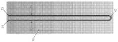
도 1 및 도 2를 참조하면, 봉합기가 오브젝트(예를 들면, 연조직)를 뼈에 고정하는데 사용될 수 있도록, 봉합기를 뼈에 고정하기 위한 신규한 봉합기 어셈블리(5)가 도시되어 있다.1 and 2, a
보다 구체적으로, 신규한 봉합기 어셈블리(5)는 일반적으로 제 1 길이의 봉합기("제 1 봉합기")(10(도 1 및 도 2 참조) 및 제 2 길이의 봉합기("제 2 봉합기")(15)(도 2 참조)를 구비한다.More specifically, the
제 1 봉합기(10)는, 제 1 단(20) 및 제 2 단(25)을 구비하며, 제 1 봉합기(10)가 둘로 접혔을 때에, 제 1 단(20)을 포함하는 제 1 아암(30), 및 제 2 단(25)을 포함하는 제 2 아암(35)을 형성하도록 하며, 제 1 아암(30)이 브리지(40)를 통하여 제 2 아암(35)에 접속되어 있다.The
제 2 봉합기(15)는, 제 1 단(45) 및 제 2 단(50)을 구비하며, 제 2 봉합기(15)가 둘로 접혔을 때에, 제 1 단(45)을 포함하는 제 1 아암(55), 및 제 2 단(50)을 포함하는 제 2 아암(60)을 형성하도록 하며, 제 1 아암(55)이 브리지(65)를 통하여 제 2 아암(60)에 접속되어 있다.The
제 2 봉합기(15)는, 도 2에 나타낸 바와 같이, (i) 브리지(65)를 통하여 서로 접속되어 있는 제 1 아암(55) 및 제 2 아암(60)을 제공하도록 제 2 봉합기(15)를 둘로 접고; (ⅱ) 제 1 봉합기의 제 1 아암(30) 및 제 2 아암(35)에 교차하여, 제 1 봉합기(10)의 브리지(40)로부터 이격되어 있는 제 2 봉합기(15)의 브리지(65)를 위치시키고; (ⅲ) 제 1 봉합기(10)의 제 1 아암(30) 둘레에 제 2 봉합기(15)의 제 1 아암(55)을 래핑하고, 제 1 봉합기(10)의 제 2 아암(35) 둘레에 제 2 봉합기(15)의 제 2 아암(60)을 래핑함으로써, 제 1 봉합기(10) 둘레에 래핑된다.As shown in FIG. 2, the
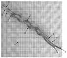
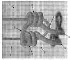
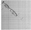
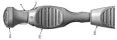
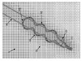
보다 구체적으로, 제 2 봉합기(15)의 제 1 아암(55)은 제 1 방향으로 제 2 봉합기(10)의 제 1 아암(30) 둘레에 래핑되고, 제 2 봉합기(15)의 제 2 아암(60)은 제 1 방향과 대향하는 제 2 방향으로 제 1 봉합기(10)의 제 2 아암(35) 둘레에 래핑된다. 즉, 제 2 봉합기(15)의 제 1 아암(55)은 제 1 봉합기(10)의 제 1 아암(30)에 대하여 제 1 나선 구조로 배치되며, 제 2 봉합기(15)의 제 2 아암(60)은 제 1 봉합기(10)의 제 2 아암(35)에 대하여 제 1 나선 구조와는 반대로 감겨진 제 2 나선 구조로 배치된다. 이와 같이 제 1 아암(55) 및 제 2 아암(65)을 반대로 감는 것은, 이후에 더욱 상세하게 설명하는 바와 같이, 신규한 봉합기 어셈블리가 그 길이방향으로 팽창되며 반경방향으로 수축되는 제 1 구성으로부터 이후에 그 길이방향으로 수축되며 반경방향으로 팽창되는 제 2 구성으로 변형될 때에 고도로 규정되고, 적절한 형상이며 일관되게 재생 가능한 구조를 갖는 신규한 봉합기 어셈블리를 제공하기 때문에, 본 발명의 매우 중요한 형태이다.More specifically, the
본 발명의 바람직한 제 1 형태에서는, 도 2에 나타낸 바와 같이, 제 1 봉합기(15)의 제 1 아암(55)이 시계방향(브리지(65)의 기준틀로부터 보았을 때) 제 1 봉합기(10)의 제 1 아암(30) 둘레에 3회 래핑되고, 제 2 봉합기(15)의 제 2 아암(60)이 반시계 방향(브리지(65)의 기준틀로부터 보았을 때)으로 제 1 봉합기(10)의 제 2 아암(35) 들레에 3회 래핑된다.In the 1st preferable form of this invention, as shown in FIG. 2, the
본 발명의 바람직한 다른 형태에서는, 제 2 봉합기(15)의 제 1 아암(55)이 시계방향(브리지(65)의 기준틀로부터 보았을 때)으로 제 1 봉합기(10)의 제 1 아암(30) 둘레에 4회 래핑되고, 제 2 봉합기(15)의 제 2 아암(60)이 반시계방향(브리지(65)의 기준틀로부터 보았을 때)으로 제 1 봉합기(10)의 제 2 아암(35) 둘레에 4회 래핑된다.In another preferred embodiment of the present invention, the
그리고 본 발명의 다른 바람직한 형태에서는, 제 2 봉합기(15)의 제 1 아암(55)이 시계방향(브리지(65)의 기준틀로부터 보았을 때)으로 제 1 봉합기(10)의 제 1 아암(30) 둘레에 2회 래핑되고, 제 2 봉합기(15)의 제 2 아암(60)이 반시계방향(브리지(65)의 기준틀로부터 보았을 때)으로 제 1 봉합기(10)의 제 2 아암(35) 둘레에 2회 래핑된다.In another preferred embodiment of the present invention, the
상기한 구조에 따라, 신규한 봉합기 어셈블리(5)는 제 2 봉합기(15)가 제 1 봉합기(10) 둘레에 느슨하게 래핑되는 제 1 구성을 상정할 수 있고, 즉, 봉합기 어셈블리는 뼈에 형성된 구멍 내에 삽입하는데 적합한, 길이방향으로 가늘고 길며 반경방향으로 수축되는 제 1 구성(도 3 및 도 4)을 상정할 수 있다. 그러나, 제 2 봉합기(15)의 브리지(65)를 정지한 상태로 유지한 채(또는 소정의 유지력, 예를 들면 봉합기 어셈블리(5)를 수용하는 뼈 구멍의 인접하는 측벽으로부터의 마찰력을 제 2 봉합기(15)에 인가함으로써) 제 1 봉합기(10)의 제 1 아암(30) 및 제 2 아암(35)에 그 후에 장력이 부여되었을 때, 봉합기 어셈블리(15)는 상기한 길이방향으로 가늘고 길며 반경방향으로 수축된 제 1 구성으로부터, 뼈에 형성된 구멍 내에 봉합기 어셈블리를 고정하는데 적합한, 길이방향으로 수축되고 반경방향으로 팽창된 제 2 구성으로 변형될 수 있다. 중요하게 그리고 이후에 더욱 상세하기 설명하는 바와 같이, 신규한 봉합기 어셈블리(5)가 뼈에 형성된 구멍 내에 배치되었을 때에, 제 1 봉합기(10)의 제 1 아암(30) 및 제 2 아암(35)은 뼈에 형성된 구멍 밖으로 연장되어, 오브젝트(예를 들면, 연조직)를 뼈에 고정하는데 사용가능할 것이다.According to the above structure, the
그리고, 중요하게는, 상기한 방식으로(예를 들면, 제 1 봉합기(10)의 제 1 아암(30) 둘레에 제 2 봉합기(15)의 제 1 아암(55)을 래핑하고, 제 1 봉합기(10)의 제 2 아암(35) 둘레에 제 2 봉합기(15)의 제 2 아암(60)을 래핑하며, 제 1 아암(55) 및 제 2 아암(60)을 제 1 아암(30) 및 제 2 아암(35) 상에 각각 반대 방향으로 감음으로써) 신규한 봉합기 어셈블리(5)를 형성함으로써, 봉합기 어셈블리(5)가 길이방향으로 팽창되고 반경방향으로 수축된 제 1 구성(도 3 및 도 4)으로부터 길이방향으로 수축되고 반경방향으로 팽창된 제 2 구성(도 5 및 도 6)으로 변형되었을 때에 도 5 및 도 6에 나타낸 고도로 규정되고 적절한 형상의 구조를 일관되게 형성할 수 있다.And, importantly, the
그리고 중요하게는, 도 5 및 도 6에 나타낸 고도로 규정되고, 적절한 형상이며 일관되게 재생 가능한 구조는, 제 1 봉합기(10)의 제 1 및 제 2 단(20, 25)에 하중이 인가될 때에 확정된 형상을 잃지 않고 실제 부하를 운반할 수 있다. 그 결과, 봉합기 어셈블리(5)가 길이방향으로 팽창되고 반경방향으로 수축된 제 1 구성인 채로 뼈 구멍 내에 삽입되고 그 후에 길이방향으로 수축되고 반경방향으로 팽창된 제 2 구성으로 변형되었을 때, 신규한 봉합기 어셈블리(5)는 유지 강도가 높은 우수한 봉합기 앵커를 제공할 것이다.And importantly, the highly defined, appropriately shaped and consistently reproducible structure shown in Figs. 5 and 6 can be applied to the first and second ends 20, 25 of the
여러가지 중에서, 전술한 바와 같이(예를 들면, 제 1 아암(30) 및 제 2 아암(35) 상에 각각 반대 방향으로 감겨있는 제 1 아암(55) 및 제 2 아암(60)을 이용하여, 제 1 봉합기(10)의 제 1 아암(30) 둘레에 제 2 봉합기(15)의 제 1 아암(55)을 래핑하고, 제 1 봉합기의 제 2 아암(35) 둘레에 제 2 봉합기(15)의 제 2 아암(60)을 래핑함으로써) 신규한 봉합기 어셈블리(5)를 형성함으로써, 신규한 봉합기 어셈블리(5)가 길이방향으로 팽창되고 반경방향으로 수축된 제 1 구성(도 3 및 도 4) 또는 길이방향으로 수축되고 반경방향으로 팽창된 제 2 구성(도 5 및 도 6) 중 어느 하나로 매듭을 형성하지 않음을 이해해야 한다. 어느 하나의 구성에서는, 신규한 봉합기 어셈블리(5)가 제 2 봉합기(15)로부터 이격해서 제 1 봉합기(10)의 제 1 아암(30)을 간단하게 당기거나, 또는 제 1 봉합기(10)의 제 2 아암(35)을 당겨서 해체되어, 봉합기 어셈블리의 "풀기(undo)"를 행할 수 있다.Among other things, as described above (for example, using the
본 발명의 하나의 바람직한 형태에서는, 제 1 봉합기(10)가 제 1 길이의 직조된(woven) 봉합기를 구비하고, 제 2 봉합기(15)가 제 2 길이의 직조된 봉합기를 구비한다.In one preferred form of the present invention, the
이와 같이, 신규한 봉합기 어셈블리(5)는, 뼈에 오브젝트(예를 들면, 연조직)를 고정하는데 사용하기 위해서 뼈에 형성된 구멍 밖으로 연장되는 한 쌍의 자유 봉합기 아암을 제공하는 봉합기 어셈블리를 이용하여, (i) 뼈에 형성된 구멍 내에 삽입하기 위한 길이방향으로 팽창되고 반경방향으로 수축된 제 1 구성, 및 (ⅱ) 뼈에 형성된 구멍에 체류하기 위해서 길이방향으로 수축되고 반경방향으로 팽창된 제 2 구성을 상정할 수 있는 모든 봉합기 구조체를 구성하는 것을 알 수 있다. 중요하게는, 전술한 특정 방식으로 신규한 봉합기 어셈블리(5)를 형성함으로써, 봉합기 어셈블리의 길이방향으로 수축되고 반경방향으로 팽창된 제 2 구성이, 확정된 형상의 손실없이 실제 부하를 운반할 수 있는 고도로 규정되고, 적절한 형상이며 일관되게 재생 가능한 구조로 되어, 유지 강도가 높은 봉합기 앵커를 제공한다. 그리고 중요하게는, 상기한 특정 방식으로 신규한 봉합기 어셈블리(5)를 형성함으로써, 신규한 봉합기 어셈블리(5)는 길이방향으로 팽창되고 반경방향으로 수축된 제 1 구성(도 3 및 도 4) 또는 길이방향으로 수축되고 반경방향으로 팽창된 제 2 구성(도 5 및 도 6) 중 어느 하나로 매듭을 형성하지 않는다. 어느 하나의 구성에서, 신규한 봉합기 어셈블리(5)는, 제 2 봉합기(15)로부터 이격해서, 제 1 봉합기(10)의 제 1 아암(30)을 간단하기 당기거나, 또는 제 1 봉합기(10)의 제 2 아암(35)을 당겨서 해체되어, 봉합기 어셈블리의 "풀기"를 행할 수 있다.As such, the
신규한New 봉합기 어셈블리를 뼈에 배치하기 위한 For placing the suture assembly to the bone신규한New인서터Inserter 어셈블리 assembly
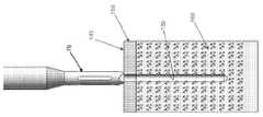
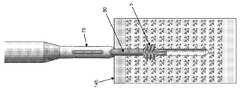
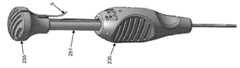
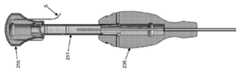
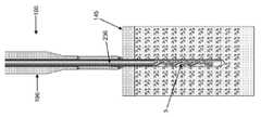
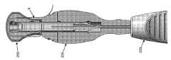
다음으로 도 7 내지 도 11을 참조하면, 신규한 봉합기 어셈블리(5)를 뼈에 배치하는데 사용될 수 있는 인서터 어셈블리(70) 및 이와 연관된 캐뉼러 부착형 드릴 가이드 어셈블리(75)가 도시되어 있다. 인서터 어셈블리(70)는 차례로 삽입 튜브 어셈블리(80) 및 푸시 로드 어셈블리(85)를 구비한다.Referring next to FIGS. 7-11, an
보다 구체적으로, 캐뉼러 부착형 드릴 가이드 어셈블리(75)는, 통상 원위단 프롱(distal end prongs)을 운반하는 원위단(90)을 갖는 가늘고 긴 드릴 가이드 튜브(86), 및 드릴 가이드 핸들(105)을 운반하는 근위단(100)을 구비한다. 루멘(106)은 가늘고 긴 드릴 가이드 튜브(86) 및 드릴 가이드 핸들(105)을 통해 연장된다.More specifically, the cannula attach
삽입 튜브 어셈블리(80)는, 통상 신규한 봉합기 어셈블리가 상기한 길이방향으로 팽창되고 반경방향으로 수축된 제 1 구성(도 3, 도 4, 도 10 및 도 11)으로 있을 때에 신규한 봉합기 어셈블리(5)를 수용할 정도의 사이즈로 된(느슨하거나, 보다 바람직하게는 밀착된) 원위단(110)을 갖는 가늘고 긴 삽입 튜브(107)를 구비한다. 삽입 튜브 어셈블리(80)의 가늘고 긴 삽입 튜브(107)는 또한 삽입 튜브 핸들(120)을 운반하는 근위단(115)을 구비한다. 루멘(12)은 가늘고 긴 삽입 튜브(107) 및 삽입 튜브 핸들(120)을 통해 연장된다.
푸시 로드 어셈블리(85)는, 통상 원위단 표면(130)으로 종단하는 원위단(125)을 갖는 푸시 로드(122), 및 푸시 로드 핸들(140)을 운반하는 근위단(135)을 구비한다.The
삽입 튜브 어셈블리(80)는, 후술하는 바와 같이, 캐뉼러 부착형 드릴 가이드 어셈블리(75)가 뼈에 구멍을 형성하는데 사용될 때에 삽입 튜브 어셈블리(80)의 원위단이 뼈 내의 구멍에 전달될 수 있도록 가늘고 긴 삽입 튜브(107)가 캐뉼러 부착형 드릴 가이드 어셈블리(75)의 루멘(106) 내에 수용될 수 있도록 하는 사이즈로 되어 있다.The
푸시 로드 어셈블리(85)는, 후술하는 바와 같이, 신규한 봉합기 어셈블리(5)가 삽입 튜브 어셈블리(80)의 가늘고 긴 삽입 튜브(107)의 원위단(110) 내에 배치될 때에, 삽입 튜브 어셈블리(80)에 대한 푸시 로드 어셈블리(85)의 전진, 및/또는 푸시 로드 어셈블리(85)를 정지한 채로 유지한 상태에서의 삽입 튜브 어셈블리(80)의 후퇴로 인해 신규한 봉합기 어셈블리(5)가 삽입 튜브 어셈블리(80)의 가늘고 긴 삽입 튜브(107)의 원위단(110)으로부터 해제되게 되도록 푸시 로드(122)가 삽입 튜브 어셈블리(80)의 루멘(121) 내에 슬라이딩 가능하게 수용될 수 있도록 하는 사이즈로 되어 있다. 신규한 봉합기 어셈블리(5)가 삽입 튜브 어셈블리(80)의 가늘고 긴 삽입 튜브(107)의 원위단으로부터 해제되면, 푸시 로드 어셈블리(85)가 제 2 봉합기(15)의 브리지(65)를 근위부쪽으로 이동하지 못하게 유지한 채로, 제 1 봉합기(10)의 제 1 아암(30) 및 제 2 아암(35)에 장력을 부여함으로써, 신규한 봉합기 어셈블리(5)가 길이방향으로 가늘고 길며 반경방향으로 수축된 제 1 구성(도 3, 도 4, 도 10 및 도 11)으로부터 길이방향으로 수축되고 반경방향으로 팽창된 제 2 구성(도 5 및 도 6)으로 변형되게 할 것이다.The
삽입 튜브 어셈블리(80)는, 또한 푸시 로드(122)가 삽입 튜브 어셈블리(80)의 루멘(121) 내에 배치되었을 때에 루멘(121)이 푸시 로드 어셈블리(85)의 푸시 로드(122)와 나란히 제 1 봉합기(10)의 제 1 및 제 2 아암(30, 35)을 수용하도록 하는 사이즈로 되어 있다.The
신규한 봉합기 어셈블리(5)는, 제 1 봉합기(10)의 제 1 아암(30) 및 제 2 아암(35)을 삽입 튜브 어셈블리(80)의 루멘(121)을 통하여 인서터 어셈블리(70)의 근위단 밖으로 연장시키고, 제 1 봉합기(10)의 제 1 아암(30) 및 제 2 아암(35)을 푸시 로드 어셈블리(85)의 푸시 로드(122)와 나란히 연장시켜서, 푸시 로드 어셈블리(85)에 대한 원위부를 삽입 튜브 어셈블리(80)의 원위단 내에 배치하려고 한다. 신규한 봉합기 어셈블리(5)는, 삽입 튜브 어셈블리(80)의 원위단 내에 밀착되어, 반경방향으로 가늘고 길며 반경방향으로 수출된 제 1 구성(도 3, 도 4, 도 10 및 도 11)과 길이방향으로 수축되고 반경방향으로 팽창된 제 2 구성(도 5 및 도 6) 간에 최대로 가능한 차분을 제공하고, 이에 따라 뼈 구멍의 사이즈를 최소화하여 뼈의 유지력을 증가시키는 것이 바람직하다. 이에 관해서, 제 1 봉합기(10)의 제 1 아암(30) 둘레에 제 2 봉합기(15)의 제 1 아암을 감고, 제 1 봉합기(10)의 제 2 아암(35) 둘레에 제 2 봉합기(15)의 제 2 아암(60)을 래핑하며, 제 1 아암(55) 및 제 2 아암(60)을 제 1 아암(30) 및 제 2 아암(35) 상에 각각 반대 방향으로 감음으로써, 제 1 및 제 2 봉합기(10, 15)가 삽입 튜브 어셈블리(80) 내부에 "자가 수용(self-accomodate)"될 수 있어, 삽입 튜브 어셈블리 내에서 신규한 봉합기 어셈블리의 최대 압착을 허용하는 것임을 이해해야 한다. 또한, 제 2 봉합기(15)의 제 1 단(45) 및 제 2 단(50)을 서로에 대하여 자유롭게 둠(즉, 미접속함)으로써, 제 1 및 제 2 봉합기(10, 15)는 삽입 튜브 어셈블리(80) 내부에서 더욱 자가 수용될 수 있어, 삽입 튜브 어셈블리 내에서 신규한 봉합기 어셈블리의 최대 압착을 허용한다. 이와 같이, 상기한 특정 방식으로 신규한 봉합기 어셈블리(5)를 형성함으로써, 봉합기 어셈블리는 삽입 튜브 어셈블리 내에서 최소한의 직경 내에 그 자체를 자가 수용할 수 있어, 삽입 튜브 어셈블리 내에서 신규한 봉합기 어셈블리의 최대 압착을 허용하고, 이에 따라 보다 작은 뼈 구멍을 사용을 허용하며, 따라서 뼈 내에서 최대 유지력을 제공한다.The
오브젝트를Object 뼈에 고정하기 위하여, To anchor to the bone,신규한New 봉합기 어셈블리를 이용하여 봉합기를 뼈에 고정하기 Securing the suture to the bone using the suture assembly
신규한 봉합기 어셈블리(5)는 봉합기가 오브젝트(예를 들면, 연조직)를 뼈에 고정하는데 사용될 수 있도록, 봉합기를 뼈에 고정하는데 사용될 수 있다.The
본 발명의 하나의 바람직한 형태에서, 인서터 어셈블리(70) 및 그와 연관된 캐뉼러 부착형 드릴 가이드 어셈블리(75)가, 오브젝트를 뼈에 고정하기 위해서, 신규한 봉학기 어셈블리(5)를 배치하는데 사용될 수 있다.In one preferred form of the present invention, the
보다 구체적으로, 본 발명의 하나의 바람직한 형태에서는, 도 12 내지 도 18을 참조하면, 우선, 캐뉼러 부착형 드릴 가이드 어셈블리(75)의 원위단이 봉합기가 고정되는 뼈(145)(도 12)의 표면에 대하여 배치된다. 그러면, 캐뉼러 부착형 드릴 가이드 어셈블리(75)의 원위단 상의 프롱(95)이 뼈에 대하여 캐뉼러 부착형 드릴 가이드 어셈블리를 안정화시키는 것을 돕는다. 그 후, 당 분야에서 잘 알려진 종류의 뼈 드릴(미도시)이 캐뉼러 부착형 드릴 가이드 어셈블리(75)의 루멘(106)을 통해 뼈 안으로 전진하여 적절한 사이즈(직경 및 깊이)의 뼈 구멍(150)이 뼈 내에 형성된다. 뼈 구멍(150)은 뼈(145)의 피층(cortical layer; 155)을 통하여 뼈의 해면(cancellous) 부위(160) 내로 연장된다. 그 후, 드릴 가이드를 뼈(145)에 대하여 제자리에 둔 채로 뼈 드릴이 캐뉼러 부착형 드릴 가이드 어셈블리(75)로부터 제거된다.More specifically, in one preferred form of the present invention, referring to FIGS. 12-18, first, the distal end of the cannula-attached
다음으로, 신규한 봉합기 어셈블리(5)를 운반하는 삽입 튜브 어셈블리(80)의 원위단(110)이 캐뉼러 부착형 드릴 가이드 어셈블리(75)를 통해 뼈(145) 내에 형성된 뼈 구멍(150) 내로 전진한다(도 13 및 도 14). 바람직하게는, 푸시 로드 어셈블리(85)의 푸시 로드(22)가 이 상태에서 삽입 튜브 어셈블리(80)의 루멘(121) 내에 미리 배치되는 것이 좋고, 푸시 로드 어셈블리(85)의 원위단(130)이 제 2 봉합기(15)의 브리지(65)에 대하여 착좌된다. 대안으로, 푸시 로드 어셈블리(85)의 푸시 로드(122)는, 삽입 튜브 어셈블리(80)의 원위단이 뼈 구멍(150) 내에 삽입되어 푸시 로드 어셈블리(85)가 제 2 봉합기(15)의 브리지(65)에 대하여 착좌한 후에 삽입 튜브 어셈블리(80)의 루멘(121) 내에 삽입될 수 있다.Next, a
다음으로, 삽입 튜브 어셈블리(80)는 푸시 로드 어셈블리(85)의 원위단(130)을 정지 상태로 유지한 채로 후퇴되어, 신규한 봉합기 어셈블리(5)가 삽입 튜브 어셈블리(80)의 원위단(110)으로부터 해제된다(도 15).Next, the
그 후, 푸시 로드 어셈블리(85)가 아직 제 2 봉합기(15)의 브리지(65)에 대하여 제자리에 있는 상태에서, 우선 제 1 봉합기(10)의 제 1 아암(30) 및 제 2 아암935)에 장력이 부여되어, 신규한 봉합기 어셈블리(5)가 그 길이방향으로 연장되고 반경방향으로 수축된 제 1 구성으로부터 그 길이방향으로 수축되고 반경방향으로 팽창된 제 2 구성으로 변형됨으로써(도 16), 신규한 봉합기 어셈블리(5)를 뼈(145)의 해면 부위(160) 내로 횡 방향으로 팽창시킨다.Then, with the
이 시점에서, 인서터 어셈블리(70) 및 캐뉼러 부착형 드릴 가이드 어셈블리(75)가 수술 부위로부터 제거되고(도 17), 제 1 봉합기(10)의 제 1 아암(30) 및 제 2 아암(35)에 더욱 장력이 부여되어서 신규한 봉합기 어셈블리(5)를 횡 방향으로 더욱 팽창시키고 횡방향으로 팽창된 신규한 봉합기 어셈블리를 뼈(145)의 피층(155)의 하측면에 대하여 착좌시켜서(도 18), 신규한 봉합기 어셈블리(5)를 뼈 구멍(150) 내에 고정시키고, 여기서 제 1 봉합기(10)의 제 1 아암(30) 및 제 2 아암(35)이 뼈 구멍 밖으로 연장된다.At this point, the
중요하게는, 전술한 방식으로(예를 들면, 제 1 봉합기(10)의 제 1 아암(30) 둘레에 제 2 봉합기(15)의 제 1 아암(55)을 래핑하고, 제 1 봉합기(10)의 제 2 아암(35) 둘레에 제 2 봉합기(15)의 제 2 아암(60)을 래핑하며, 제 1 아암(55) 및 제 2 아암(60)을 제 1 아암(30) 및 제 2 아암(35) 상에 각각 반대 방향으로 감음으로써) 신규한 봉합기 어셈블리(5)를 형성함으로써, 봉합기 어셈블리(5)가 길이방향으로 팽창되고 반경방향으로 수축된 제 1 구성(도 3 및 도 4)으로부터 길이방향으로 수축되고 반경방향으로 팽창된 제 2 구성(도 5 및 도 6)으로 변형될 때에 고도로 지속되는 방식으로 도 5 및 도 6에 나타낸 고도로 규정되고, 적절한 형상의 구조체를 형성할 수 있다.Importantly, the
그리고 중요하게는, 도 5 및 도 6에 나타낸 고도로 확정되고, 적절한 형상의 지속적으로 재생 가능한 구조체는 제 1 봉합기(10)의 제 1 및 제 2 단(20, 25)에 부하가 인가되었을 때에 그 규정된 형상의 손실없이 실제 부하를 운반할 수 있다. 그 결과, 봉합기 어셈블리(5)가 그 길이방향으로 팽창되고 반경방향으로 수축된 제 1 구성인 채로 뼈 구멍 내에 삽입되고, 그 후에 길이방향으로 수축되고 반경방향으로 팽창된 제 2 구성으로 변형되었을 때에, 신규한 봉합기 어셈블리(5)는 유지 강도가 높은 우수한 봉합기 앵커를 제공할 것이다.And importantly, the highly determined, consistently reproducible structure shown in FIGS. 5 and 6 is applied when the load is applied to the first and
그 후, 제 1 봉합기(10)의 제 아암(30) 및 제 2 아암(35) 중 하나 또는 양쪽을 사용하여 오브젝트(예를 들면, 연조직)를 뼈에 고정시킬 수 있다. 한정은 아니지만 본 예를 이용하여, 제 1 아암(30) 및 제 2 아암(35) 중 하나 또는 양쪽을 한 조각의 연조직(예를 들면, 인대)을 통과하고 나서 함께 묶어서 연조직을 뼈에 고정시킬 수 있다.Thereafter, one or both of the
중요하게는, 전술한 방식으로(예를 들면, 제 1 봉합기(10)의 제 1 아암(30) 둘레에 제 2 봉합기(15)의 제 1 아암(55)을 래핑하고, 제 1 봉합기(10)의 제 2 아암(35) 둘레에 제 2 봉합기(15)의 제 2 아암(60)을 래핑하며, 제 1 아암(55) 및 제 2 아암(60)을 제 1 아암(30) 및 제 2 아암(35) 상에 각각 반대 방향으로 감음으로써) 신규한 봉합기 어셈블리(5)를 형성함으로써, 신규한 봉합기 어셈블리(5)는 길이방향으로 팽창되고 반경방향으로 수축된 제 1 구성(도 3 및 도 4) 또는 길이방향으로 수축되고 반경방향으로 팽창된 제 2 구성(도 5 및 도 6) 중 어느 하나로 매듭을 형성하지 않는다. 어느 하나의 구성에서, 신규한 봉합기 어셈블리(5)는, 제 2 봉합기(15)로부터 이격해서, 제 1 봉합기(10)의 제 1 아암(30)을 간단하게 당기거나, 또는 제 1 봉합기(10)의 제 2 아암(35)을 당겨서 해체되어, 봉합기 어셈블리의 "풀기"를 행할 수 있다. 그 결과, 언제라도 신규한 봉합기 어셈블리(5)를 뼈 구멍(150)으로부터 제거하려고 하는 경우에, 제 1 봉합기(10)의 제 1 아암(30), 또는 제 1 봉합기(10)의 제 2 아암(35)을 제 2 봉합기(15)로부터 이격해서 간단히 당겨서, 봉합기 어셈블리의 "풀기"를 행한다. 제 1 봉합기(10)가 수술 부위를 피해서 당겨지면, 제 2 봉합기(15)는 뼈 구멍(150)(예를 들면, 좁은 봉합기 파지기)로부터 추출되어 수술 부위로부터 제거될 수 있다.Importantly, the
이하, 본 발명의 다른 바람직한 형태로서, 도 19 내지 도 26을 참조하면, 우선 캐뉼러 부착형 드릴 가이드 어셈블리(75)의 원위단이 뼈(145)의 표면에 위치되고, 이어서 적합한 사이즈(직경 미 깊이)의 뼈 구멍(150)이 뼈에 형성되도록 뼈 드릴(도시 생략)이 캐뉼러 부착형 드릴 가이드 어셈블리(75)의 루멘(106)을 통해 뼈 내로 전진하고, 이어서 뼈 드릴을 캐뉼러 부착형 드릴 가이드 어셈블리(75)로부터 제거함과 함께 뼈(145) 위치 내의 캐뉼러 부착형 드릴 가이드 어셈블리를 빼내고, 이어서 내부에서 신규한 봉합기 어셈블리(5)를 반송하는 삽입 튜브 어셈블리(80)의 원위단(110)이 캐뉼러 부착형 드릴 가이드 어셈블리(75)를 통해 뼈(145)에 형성된 뼈 구멍(150) 내로 전진한다(도 19 및 도 20 참조). 이 때, 푸시 로드 어셈블리(85)의 푸시 로드(122)가 삽입 튜브 어셈블리(80)의 루멘(121) 내에 이미 배치되어 있으며, 푸시 로드 어셈블리(85)의 원위단(130)이 제 2 봉합기(15)의 브리지(65)에 놓이는 것이 바람직하다. 또는, 푸시 로드 어셈블리(85)의 원위단(130)이 제 2 봉합기(15)의 브리지(65)에 놓이도록 삽입 튜브 어셈블리(80)의 원위단이 뼈 구멍(150) 내에 삽입된 후에, 푸시 로드 어셈블리(85)의 푸시 로드(122)가 삽입 튜브 어셈블리(80)의 루멘(121) 내로 삽입될 수 있다.Hereinafter, as another preferred form of the present invention, referring to FIGS. 19 to 26, first, the distal end of the cannula-attached
이어서, 푸시 로드 어셈블리(85)가 제 2 봉합기(15)의 브리지(65)에 대해 원위단 방향으로 전진되어, 봉합기 어셈블리(5)가 삽입 튜브 어셈블리(80)의 원위단(110)으로부터 배출된다(도 21 및 도 22).The
이어서, 푸시 로드 어셈블리(85)가 제 2 봉합기(15)의 브리지(65)에 위치되어 있는 상태에서, 제 1 봉합기(10)의 제 1 아암(30) 및 제 2 아암(35)에 장력을 가함으로써, 신규한 봉합기 어셈블리(5)를 길이방향으로 연장되고 반경방향으로 수축된 제 1 구성으로부터 길이방향으로 수축되고, 반경방향으로 팽창된 제 2 구성으로 변형함으로써(도 23 및 도 24), 신규한 봉합기 어셈블리(5)를 뼈(145)의 해면(cancellous) 부위(160) 내로 횡방향으로 팽창시킨다.Subsequently, with the
이 때, 삽입 어셈블리(70) 및 캐뉼러 부착형 드릴 가이드 어셈블리(75)는 수술 부위에서 제거되며(도 25), 제 1 봉합기(10)의 제 1 아암(30) 및 제 2 아암(35)은 더 장력을 받아 봉합기 어셈블리(5)를 더 횡방향으로 팽창시키고 횡방향으로 팽창된 신규한 봉합기 어셈블리가 뼈(145)의 피층(cortical layer)(155)의 하부에 놓이게 함으로써(도 26), 제 1 아암(30) 및 제 2 아암(35)이 뼈 구멍 외부로 연장되면서 뼈 구멍(150) 내에 신규한 봉합기 어셈블리(5)를 고정한다(도 26).At this time, the
또한, 전술한 방식으로 신규한 봉합기 어셈블리(5)를 형성함으로써(예를 들면 제 1 봉합기(10)의 제 1 아암(30) 둘레에 제 2 봉합기(15)의 제 1 아암(55)을 감고 제 1 봉합기(10)의 제 2 아암(35) 둘레에 제 2 봉합기(15)의 제 2 아암(60)을 감으며, 제 1 아암(55) 및 제 2 아암(60)이 제 1 아암(30) 및 제 2 아암(35) 상에서 반대 방향으로 각각 감김으로써), 길이방향으로 팽창되고 반경방향으로 수축된 제 1 구성(도 3 및 도 4)으로부터 길이방향으로 수축되고 반경방향으로 팽창된 제 2 구성(도 5 및 도 6)으로 신규한 봉합기 어셈블리(5)가 변형될 때, 매우 일관되게 도 5 및 도 6에 나타낸 고도로 규정되고, 적절한 형상의 구조를 형성할 수 있다.The
또한, 도 5 및 도 6에 나타낸 고도로 규정되고, 적절한 형상이며 일관되게 재생 가능한 구조는, 제 1 봉합기(10)의 제 1 및 제 2 단부(20, 25)에 부하가 가해질 경우 규정된 형상을 잃지 않고 실제의 부하를 전달할 수 있다. 결과적으로, 봉합기 어셈블리(5)가 뼈 구멍에 삽입됨과 함께 길이방향으로 팽창되고 반경방향으로 수축된 제 1 구성으로부터 길이방향으로 수축되고 반경방향으로 팽창된 제 2 구성으로 변형될 때, 신규한 봉합기 어셈블리(5)는 높은 유지력를 갖는 우수한 봉합기 앵커를 제공한다.In addition, the highly defined, appropriately shaped and consistently reproducible structure shown in FIGS. 5 and 6 is a defined shape when a load is applied to the first and second ends 20, 25 of the
일 테스트 구성에서, 전술한 바와 같이 구성되는 봉합기 어셈블리(5)가, 깊이가 약 20㎜~25㎜인 2㎜ 폼 뼈(foam bone) 구멍 내에 제공되었다. 매체는 3㎜의 두께, 20 듀로미터(durameter) 폼 뼈 블록을 넘는 55-60 듀로미터 폼 뼈층이었다(Pacific Research Sawbones). 폼 뼈 내에의 삽입 후의 봉합기 어셈블리의 최대 인장 강도는 약 77 파운드였다. 1.5㎜ 폼 뼈 구멍 내에의 삽입 후의 다른 봉합기 어셈블리에 대한 최대 인장 강도는 약 50 파운드였다.In one test configuration, a
그 후, 제 1 봉합기(10)의 제 1 아암(30) 및 제 2 아암(35) 중 하나 또는 양쪽 모두는 오브젝트(예를 들면, 연조직)를 뼈에 고정하는 데 사용될 수 있다. 한정이 아닌 예로써, 제 1 아암(30) 및 제 2 아암(35) 중 하나 또는 양쪽 모두는 하나의 연조직(예를 들면, 인대)을 통과하고 연조직을 뼈에 고정하도록 함께 묶일 수 있다.Thereafter, one or both of the
또한, 전술한 방식으로 신규한 봉합기 어셈블리(5)를 형성함으로써(예를 들면 제 1 봉합기(10)의 제 1 아암(30) 둘레에 제 2 봉합기(15)의 제 1 아암(55)을 감고 제 1 봉합기(10)의 제 2 아암(35) 둘레에 제 2 봉합기(15)의 제 2 아암(60)을 감으며, 제 1 아암(55) 및 제 2 아암(60)이 제 1 아암(30) 및 제 2 아암(35) 상에서 반대 방향으로 각각 감김으로써), 신규한 봉합기 어셈블리(5)가 길이방향으로 팽창되고, 반경방향으로 수축된 제 1 구성(도 3 및 도 4) 또는 길이방향으로 수축되고 반경방향으로 팽창된 제 2 구성(도 5 및 도 6)에서 매듭을 형성하지 않음을 이해할 것이다. 어떠한 구성에서도, 제 1 봉합기(10)의 제 1 아암(30)을 간단히 당기거나, 제 1 봉합기(10)의 제 2 아암(35)을 당겨서 신규한 봉합기 어셈블리(5)가 제 2 봉합기(15)로부터 해제됨으로써, 봉합기 어셈블리를 푼다. 결과적으로, 언제든지 뼈 구멍(150)으로부터 신규한 봉합기 어셈블리(5)를 제거하는 것이 필요할 경우, 제 1 봉합기(10)의 제 1 아암(30) 또는 제 1 봉합기(10)의 제 2 아암(35)을 제 2 봉합기(15)로부터 간단히 당김으로써, 봉합기 어셈블리의 "풀기"를 행한다. 제 1 봉합기(10)가 수술 부위에서 당겨서 없어졌다면, 제 2 봉합기(15)는 뼈 구멍(150)로부터 (예를 들면, 좁은 봉합기 파지기로) 추출되어 수술 부위에서 제거될 수 있다.The
본 발명의 신규한 봉합기 어셈블리는 폭넓은 해부학적 적용에 따른 사이즈로 될 수 있는 데 의의가 있다. 한정이 아닌 예시로써, 신규한 봉합기 어셈블리는 비교적 미세한 봉합기 및 비교적 적은 수의 봉합기 루프를 갖고 형성되어, 작고 섬세한 해부학적 구조로의 사용을 위해 비교적 작은 구조를 제공할 수 있다. 이러한 유형의 신규한 봉합기 어셈블리는 예를 들면 약 1㎜의 매우 작은 뼈 구멍을 통해 전해질 수 있다. 따라서, 신규한 봉합기 어셈블리는 비교적 큰 봉합기 및 비교적 많은 수의 봉합기 루프로 형성될 수 있어, 강건한(robust) 해부학적 구조로 사용을 위해 비교적 큰 구조를 제공할 수 있다. 전술한 방식으로 신규한 봉합기 어셈블리(5)를 형성함으로써(예를 들면, 제 1 봉합기(10)의 제 1 아암(30) 둘레에 제 2 봉합기(15)의 제 1 아암(55)을 감고 제 1 봉합기(10)의 제 2 아암(35) 둘레에 제 2 봉합기(15)의 제 2 아암(60)을 감으며, 제 1 아암(55) 및 제 2 아암(60)이 제 1 아암(30) 및 제 2 아암(35) 상에서 반대 방향으로 각각 감김으로써), 봉합기 어셈블리(5)는 길이방향으로 팽창되고, 반경방향으로 수축된 제 1 구성(도 3 및 도 4)으로부터 길이방향으로 수축되고 반경방향으로 팽창된 제 2 구성(도 5 및 도 6)으로 변형될 때, 매우 일관되게 도 5 및 도 6에 나타낸 고도로 규정되고, 적절한 형상의 구조를 형성할 수 있는 데 의의가 있다. 그리고, 도 5 및 도 6에 나타낸 고도로 규정되고, 적절한 형상이며 일관되게 재생 가능한 구조는, 제 1 봉합기(10)의 제 1 및 제 2 단부(20, 25)에 부하가 가해질 경우 규정된 형태를 잃지 않고 실제의 부하를 전달할 수 있으므로, 봉합기 어셈블리(5)가 사이즈에 대해(및 호스트 뼈에 만들어진 구멍의 사이즈에 대해) 높은 유지력을 갖는 우수한 봉합기 앵커를 제공한다.The novel suture assembly of the present invention is significant in that it can be sized for a wide range of anatomical applications. By way of example and not limitation, the novel suture assembly may be formed with a relatively fine suture and a relatively small number of suture loops to provide a relatively small structure for use with a small, delicate anatomical structure. Novel suture assemblies of this type can be delivered through very small bone holes, for example about 1 mm. Thus, the novel suture assembly can be formed with a relatively large suture and a relatively large number of suture loops, providing a relatively large structure for use as a robust anatomical structure. By forming the
또한, 본 발명의 신규한 봉합기 어셈블리는 오브젝트를 뼈 이외의 구조에 부착할 수 있으며, 예를 들면 신규한 봉합기 어셈블리는 피부를 근육에 부착하는 데 사용될 수 있다.In addition, the novel suture assemblies can attach objects to structures other than bone, for example, the new suture assemblies can be used to attach skin to muscles.
신규한New 봉합기 어셈블리를 배치하기 위한 대체의 Alternative to Place Suture Assembly인서터Inserter 어셈블리 assembly
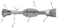
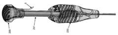
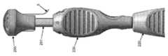
이어서, 도 27 내지 도 31을 참조하면, 뼈에 신규한 봉합기 어셈블리(5)를 배치하는 데 사용될 수 있는 인서터 어셈블리(190) 및 관련 캐뉼러 부착형 드릴 가이드 어셈블리(195)가 나타나 있다. 인서터 어셈블리(190)는 차례대로 삽입 튜브 어셈블리(200) 및 푸시 로드 어셈블리(205)를 포함한다.27-31, there is shown an
구체적으로, 드릴 가이드 어셈블리(195)는 일반적으로, 원위단 프롱(211)을 유지하는 원위단(210) 및 드릴 가이드 핸들(220)을 유지하는 근위단(215)을 포함하는 가늘고 긴 드릴 가이드 튜브(196)를 포함한다. 루멘(221)은 가늘고 긴 드릴 가이드 튜브(196) 및 드릴 가이드 핸들(220)을 통해 연장된다.Specifically, the
삽입 튜브 어셈블리(200)는 일반적으로, 신규한 봉합기 어셈블리가 전술한 길이방향으로 팽창되고 반경방향으로 수축된 제 1 구성(도 3 및 도 4)일 때 신규한 봉합기 어셈블리(5)(느슨하거나 바람직하게는 밀착됨)를 수용하는 사이즈로 된 원위단(225)을 갖는 가늘고 긴 삽입 튜브(201)를 포함한다. 또한, 삽입 튜브 어셈블리(200)의 가늘고 긴 삽입 튜브(201)는 삽입 튜브 핸들(235)을 지지하는 근위단(230)을 포함한다. 루멘(231)은 가늘고 긴 삽입 튜브(201) 및 삽입 튜브 핸들(235)을 통과 연장된다.
푸시 로드 어셈블리(205)는 원위단면(245)에서 끝나는 원위단(240), 및 푸시 로드 슬라이드(251)에서 끝나는 근위단(240)을 일반적으로 포함한다. 푸시 로드 슬라이드(251)는 후술하는 봉합기 슬롯(252) 및 봉합기 새들(saddle)(253)을 포함한다. 푸시 로드 핸들(255)은 푸시 로드 핸들이 푸시 로드 슬라이드에 대해 길이방향으로 이동 가능하게 푸시 로드 슬라이드(251)에 슬라이드 가능하게 장착된다. 푸시 로드 핸들(255) 상의 상대 엘리먼트(257)와 결합하는 푸시 로드 슬라이드(251) 상에 반경방향 돌출부(256)를 포함하는 디텐트 메커니즘은 적절한 크기의 힘이 푸시 로드 핸들(255)에 인가되어 결과적으로 푸시 로드 핸들(255)은 푸시 로드 슬라이드(251)에 대해 이동할 때까지, 푸시 로드 핸들(255)을 푸시 로드 슬라이드(251) 상의 위치에 유지한다(후술함). 푸시 로드 핸들(255)은 봉합기를 푸시 로드 핸들에 해제 가능하게 바인딩하기 위한 소형의 슬롯(258)을 포함한다.Push
삽입 튜브 어셈블리(200)는, 캐뉼러 부착형 드릴 가이드 어셈블리(195)가 뼈에 구멍을 형성하는 데 사용될 때, 삽입 튜브 어셈블리(200)의 원위단이 뼈 내의 구멍에 전해질 수 있도록, 가늘고 긴 삽입 튜브(201)가 캐뉼러 부착형 드릴 가이드 어셈블리(195)의 루멘(221) 내에 수용될 수 있는 사이즈로 된다(후술함).
푸시 로드 어셈블리(205)는 삽입 튜브 어셈블리(200)의 루멘(231) 내에 슬라이드 가능하게 수용될 수 있는 사이즈로 되어, 신규한 봉합기 어셈블리(5)가 삽입 튜브 어셈블리(200)의 가늘고 긴 삽입 튜브(201)의 원위단(225) 내에 배치될 때, 삽입 튜브 어셈블리(200)에 대한 푸시 로드 어셈블리(205)의 전진이 신규한 봉합기 어셈블리(5)가 삽입 튜브 어셈블리(200)의 가늘고 긴 삽입 튜브(201)의 원위단(225)으로부터 배출되게 한다(후술함). 신규한 봉합기 어셈블리(5)가 삽입 튜브 어셈블리(200)의 삽입 튜브(201)의 원위단(225)으로부터 배출되었을 경우, 제 1 봉합기(10)의 제 1 아암(30) 및 제 2 아암(35)에 장력을 부여하는 것은, 푸시 로드 어셈블리(205)가 제 2 봉합기(15)의 브리지(65)가 근위단 방향으로 움직이는 것을 방지하면서, 봉합기 어셈블리(5)가 길이방향으로 연장되고, 반경방향으로 수축되는 제 1 구성(도 3 및 도 4)으로부터 길이방향으로 수축되고 반경방향을 팽창된 제 2 구성(도 5 및 도 6)으로 변형되게 한다. 푸시 로드 슬라이드(251)를 따라 푸시 로드 핸들(255)을 길이방향으로 이동시킴으로써(즉, 적절한 크기의 힘이 전술한 디텐트 메커니즘에 가해짐으로써), 이 제 1 봉합기(10)의 제 1 아암(30) 및 제 2 아암(35)의 장력이 부여될 수 있다(후술함).The
또한, 삽입 튜브 어셈블리(200)는, 푸시 로드(236)가 삽입 튜브 어셈블리(200)의 루멘(231) 내에 배치될 때 푸시 로드 어셈블리(205)의 푸시 로드(236)와 나란히 제 1 봉합기(10)의 제 1 아암(30) 및 제 2 아암(35)을 수용하는 사이즈로 된다.In addition, the
신규한 봉합기 어셈블리(5)는 푸시 로드 어셈블리(205)에 원위단 방향인 삽입 튜브 어셈블리(200)의 원위단에 배치되게 하고, 제 1 봉합기(10)의 제 1 아암(30) 및 제 2 아암(35)은 삽입 튜브 어셈블리(200)의 루멘(231)(및 푸시 로드 어셈블리(205)의 푸시 로드(236)와 나란히) 위이고, 푸시 로드 슬라이드(251)의 봉합기 슬롯(252)을 따르며, 푸시 로드 슬라이드(251)의 봉합기 새들(253) 둘레로 이어지며, 이어서 푸시 로드 핸들(255)의 소형의 슬롯(258) 내로 연장됨으로써, 제 1 봉합기(10)의 제 1 아암(30) 및 제 2 아암(35)을 푸시 로드 핸들(255)에 해제 가능하게 바인딩하는 것을 의도하고 있다. 길이방향으로 연장되고 반경방향으로 수축된 제 1 구성(도 3 및 도 4)의 길이방향으로 수축되고 반경방향으로 팽창된 제 2 구성(도 5 및 도 6) 사이의 직경에 가능한 가장 큰 차이를 제공하도록, 신규한 봉합기 어셈블리(5)를 삽입 튜브 어셈블리(200)의 원위단 내에 타이트하게 압착함으로써, 본딩 구멍의 사이즈를 최소화하여 뼈 내에서 유지력을 증가시키는 것이 바람직하다. 이 점에서, 제 1 봉합기(10)의 제 1 아암(30) 둘레에 제 2 봉합기(15)의 제 1 아암(55)을 감고 제 1 봉합기(10)의 제 2 아암(35) 둘레에 제 2 봉합기(15)의 제 2 아암(60)을 감으며, 제 1 아암(55) 및 제 2 아암(60)이 제 1 아암(30) 및 제 2 아암(35) 상에서 반대 방향으로 각각 감김으로써, 제 1 봉합기(10) 및 제 2 봉합기(15)가 삽입 튜브 어셈블리(200)의 내부에 "자가 수용"할 수 있음으로써, 삽입 튜브 내의 신규한 봉합기 어셈블리의 최대 압착을 허용할 수 있음을 이해할 것이다. 또한, 제 2 봉합기(15)의 제 1 단부(45) 및 제 2 단부(50)를 서로에 대해 자유롭게 함으로써(즉, 비연결), 제 1 및 제 2 봉합기(10, 15)는 삽입 튜브 어셈블리(200)의 내부에 더 자가 수용될 수 있음으로써, 삽입 튜브 어셈블리 내에 신규한 봉합기 어셈블리의 최대 압착을 허용할 수 있다. 따러서, 전술한 특정 방식으로 신규한 봉합기 어셈블리(5)를 형성함으로써, 봉합기 어셈블리는 자신을 삽입 튜브 어셈블리 내에서 가능한 가장 작은 직경으로 자가 수용할 수 있음으로써, 삽입 튜브 어셈블리 내에 신규한 봉합기 어셈블리의 최대 압착할 수 있으며, 이에 따라 더 작은 뼈 구멍의 이용을 가능하게 하며, 이에 따라 뼈 내에 최대 유지력을 제공할 수 있음을 이해할 것이다.The
푸시 로드 핸들(255)은 디텐트 메커니즘을 이용하여 푸시 로드 슬라이드(251)에 슬라이드 가능하게 장착되고, 우선 제 1 봉합기(10)의 제 1 아암(30) 및 제 2 아암(35)이 푸시 로드 슬라이드(251)의 봉합기 새들(253) 위를 지나간 후에 푸시 로드 핸들(255)에 해제 가능하게 고정되어서, (i) 전술한 디텐트 메커니즘의 트리거 크기보다 작게 푸시 로드 핸들(255)에 힘을 처음에 가함으로써, 처음에 푸시 로드 핸들(255)은 푸시 로드 어셈블리(205)가 삽입 튜브 어셈블리(205)에 대해 원위단 방향으로 이동하게 하고, 이로써 삽입 튜브 어셈블리(200)로부터 봉합기 어셈블리(205)를 배출하고, (ii) 그 후, 전술한 디텐트 메커니즘의 트리거 크기보다 크게 푸시 로드 핸들(255)에 힘을 가함으로써, 푸시 로드 핸들(255)은 푸시 로드 슬라이드(251)에 대해 움직이고, 이로써 푸시 로드(236)를 더 원위단 방향으로 움직이지 않고 제 1 봉합기(10)의 제 1 아암(30) 및 제 2 아암(35)에 장력이 가해지게 한다는 점에 의의가 있다.The
따라서, 본 발명의 이러한 형태로 인해, 신규한 봉합기 어셈블리(5)가 삽입 튜브 어셈블리(200)의 원위단(225)으로부터 배출되면, 제 1 봉합기(10)의 제 1 아암(30) 및 제 2 아암(35)은 자동적으로 장력이 부여되며, 푸시 로드 어셈블리(205)가 제 2 봉합기(15)의 브리지(65)가 근위단 방향으로 이동하는 것을 방지함으로써, 신규한 봉합기 어셈블리(5)가 길이방향으로 연장되고 반경방향으로 수축된 제 1 구성(도 3 및 도 4)으로부터 길이방향으로 수축되고 반경방향으로 팽창된 제 2 구성(도 5 및 도 6)으로 변형되게 한다.Thus, with this form of the invention, once the
본질적으로, 본 발명의 이러한 형태에서, 푸시 로드 핸들(255)의 원위단 방향의 전진 이동은 신규한 봉합기 어셈블리(5)가 처음에 뼈 구멍 내에 배출되게 하고, 이어서 길이방향으로 연장되고 반경방향으로 수축된 제 1 구성으로부터 길이방향으로 수축되고 반경방향으로 팽창된 제 2 구성으로 변형되게 한다.In essence, in this form of the invention, the distal forward movement of the push rod handle 255 causes the
새로운 구조 어셈블리를 배치하기 위한 대체의Alternative to placing a new structural assembly인서터Inserter 어셈블리의 사용 Use of assembly
오브젝트를Object 뼈에 고정하기 Pin to bone
오브젝트를 뼈에 고정하기 위해, 도 27 내지 도 31에 나타낸 대체의 인서터 어셈블리(190) 및 관련 캐뉼러 부착 드릴 가이드 어셈블리(195)가, 신규한 봉합기 어셈블리(5)를 뼈 내에 배치하는 데 사용될 수 있다.To secure the object to the bone, the
이에 따라, 본 발명의 다른 바람직한 형태에서, 이하 도 32 내지 도 49를 참조하면, 캐뉼러 부착 드릴 가이드 어셈블리(195)의 원위단은 처음에 뼈(145)의 표면에 위치되고, 공지의 종류의 뼈 드릴(도시 생략)이, 적합한 사이즈(직경 및 깊이)의 뼈 구멍(150)이 뼈 내에 형성되도록 캐뉼러 부착 드릴 가이드 어셈블리의 루멘(221)을 통해 뼈 내로 전진하고, 이어서 뼈 드릴이 캐뉼러 부착 드릴 가이드 어셈블리(195)의 루멘(221)으로부터 제거됨과 함께 뼈(145)의 위치에서 캐뉼러 부착 드릴 가이드 어셈블리를 빼내고, 이어서 내부에 새로운 수리 봉합기(5)를 지지하는 삽입 튜브 어셈블리(200)의 원위단(225)이 캐뉼러 부착 드릴 가이드 어셈블리(195)를 통해 뼈(145) 내에 형성된 뼈 구멍(150) 내로 전진한다(도 32 내지 도 38). 이 때, 푸시 로드 어셈블리(205)의 푸시 로드(236)가 삽입 튜브 어셈블리(200)의 루멘(231) 내에 이미 배치되어 있으며, 푸시 로드 어셈블리(205)의 원위단(240)은 제 2 봉합기(15)의 브리지(65)에 놓여 있음을 이해할 것이다.Accordingly, in another preferred form of the present invention, referring now to FIGS. 32-49, the distal end of the cannula attached
다음으로, 푸시 로드 어셈블리(205)는 제 2 봉합기(15)의 브리지(65)에 대해 원위단 방향으로 전진해서, 신규한 봉합기 어셈블리(5)는 삽입 튜브 어셈블리(200)의 원위단(225)으로부터 배출된다(도 39 내지 도 43). 이는, 푸시 로드 핸들(255)을 원위단 방향으로 가압함으로써 행해져, 푸시 로드 어셈블리(205)가 삽입 튜브(200)에 대해 원위단 방향으로 전진하게 한다. 이 때, 푸시 로드 슬라이드(251) 상의 반경방향 돌출부(256) 및 푸시 로드 핸들(255) 상의 상대 엘리먼트(257)의 디텐트 메커니즘에 기인해 푸시 로드 핸들(255)은 푸시 로드 슬라이드(251) 상의 위치에 고정된다. 푸시 로드 어셈블리(205)는 푸시 로드 슬라이드(251)가 삽입 튜브 핸들(235) 상의 시트(seat)에 닿을 때까지 원위단 방향으로 전진하다(도 41).Next, the
이어서, 푸시 로드 어셈블리(205)는 제 2 봉합기(15)의 브리지(65)에 대한 위치에 있고, 제 1 봉합기(10)의 제 1 아암(30) 및 제 2 아암(35)이 장력을 받고, 이에 의해 신규한 봉합기 어셈블리(5)는 길이방향으로 연장되고, 반경방향으로 수축된 제 1 구성으로부터 길이방향으로 수축되고 반경방향으로 팽창된 제 2 구성으로 변형되고(도 44 내지 도 47), 이에 의해 신규한 봉합기 어셈블리(5)를 뼈(145)의 해면 부위(160) 내에 횡방향으로 팽창시킨다. 이는, 푸시 로드 핸들(255)을 더 원위단 방향으로 가압하여 행해져, 푸시 로드 핸들(255)이 푸시 로드 슬라이드(251)로 전술한 디텐트 메커니즘을 극복함으로써 푸시 로드 핸들(255)이 삽입 튜브 어셈블리(200) 및 푸시 로드 어셈블리(205)에 대해 푸시 로드 슬라이드(251)를 따라 원위단 방향으로 움직이게 한다. 이 때, 봉합기 새들(253) 둘레에 생성된 봉합기 경로의 길이 증가로 인해, 제 1 봉합기(10)의 제 1 아암(30) 및 제 2 아암(35)은 장력 부여된다.The
이 때, 제 1 봉합기(10)의 제 1 아암(30) 및 제 2 아암(35)은 인서터 어셈블리(190)로부터 해제되며(예를 들면, 푸시 로드 핸들(255)의 소형의 슬롯(258)으로부터 봉합기 아암을 장착 해제함으로써), 인서터 어셈블리(190)는 수술 부위로부터 제거되며(도 48), 이어서 제 1 봉합기(10)의 제 1 아암(30) 및 제 2 아암(35)은 더 장력 부여되어서 신규한 봉합기 어셈블리(5)를 횡방향으로 더 팽창시키고, 횡방향으로 팽창된 신규한 봉합기 어셈블리가 뼈(145)의 피층(155)의 하측에 놓이게 함으로써(도 49), 뼈 구멍(150) 내에 신규한 봉합기 어셈블리(5)를 고정하고, 제 1 봉합기(10)의 제 1 아암(30) 및 제 2 아암(35)은 뼈 구멍 밖으로 연장된다.At this time, the
전술한 방식으로 신규한 봉합기 어셈블리(5)를 형성함으로써(예를 들면, 제 1 봉합기(10)의 제 1 아암(30) 둘레에 제 2 봉합기(15)의 제 1 아암(55)을 감고 제 1 봉합기(10)의 제 2 아암(35) 둘레에 제 2 봉합기(15)의 제 2 아암(60)을 감으며, 제 1 아암(55) 및 제 2 아암(60)이 제 1 아암(30) 및 제 2 아암(35) 상에서 반대 방향으로 각각 감김으로써), 봉합기 어셈블리(5)가, 길이방향으로 팽창되고 반경방향으로 수축된 제 1 구성(도 3 및 도 4)으로부터 길이방향으로 수축되고 반경방향으로 팽창된 제 2 구성(도 5 및 도 6)으로 변형될 때, 매우 일관되게 도 5 및 도 6에 나타낸 고도로 규정되고, 적절한 형상의 구조를 형성할 수 있다는 점에 의의가 있다.By forming the
또한 도 5 및 도 6에 나타낸 고도로 규정되고, 적절한 형상이며 일관되게 재생 가능한 구조는, 제 1 봉합기(10)의 제 1 및 제 2 단부(20, 25)에 부하가 가해질 경우 규정된 형태를 잃지 않고 실제의 부하를 전달할 수 있는 데 의의가 있다. 결과적으로, 봉합기 어셈블리(5)가 뼈 구멍 내에 삽입되면서, 길이방향으로 팽창되고, 반경방향으로 수축된 제 1 구성으로부터 길이방향으로 수축되고 반경방향으로 팽창된 제 2 구성으로 변형될 경우, 신규한 봉합기 어셈블리(5)는 높은 유지력을 갖는 우수한 봉합기 앵커를 제공한다.In addition, the highly defined, appropriately shaped and consistently reproducible structures shown in FIGS. 5 and 6 have a defined form when a load is applied to the first and second ends 20, 25 of the
그 후, 제 1 봉합기(10)의 제 1 아암(30) 및 제 2 아암(35) 중 하나 또는 양쪽 모두는 오브젝트(예를 들면, 연조직)를 뼈에 고정하는 데 사용될 수 있다. 한정이 아닌 예시로서, 제 1 아암(30) 및 제 2 아암(35) 중 하나 또는 양쪽 모두는 하나의 연조직(예를 들면, 인대)를 통과하고, 이어서 연조직을 뼈에 고정하도록 묶일 수 있다.Thereafter, one or both of the
또한, 전술한 방식으로 신규한 봉합기 어셈블리(5)를 형성함으로써(예를 들면, 제 1 봉합기(10)의 제 1 아암(30) 둘레에 제 2 봉합기(15)의 제 1 아암(55)을 감고 제 1 봉합기(10)의 제 2 아암(35) 둘레에 제 2 봉합기(15)의 제 2 아암(60)을 감으며, 제 1 아암(55) 및 제 2 아암(60)이 제 1 아암(30) 및 제 2 아암(35) 상에서 반대 방향으로 각각 감김으로써), 신규한 봉합기 어셈블리(5)가, 길이방향으로 팽창되고 반경방향으로 수축된 제 1 구성(도 3 및 도 4) 또는 길이방향으로 수축되고 반경방향으로 팽창된 제 2 구성(도 5 및 도 6)의 어느 것에서도 매듭을 형성하지 않음을 이해할 것이다. 어떠한 구성에서도, 신규한 봉합기 어셈블리(5)가 제 2 봉합기(15)로부터, 제 1 봉합기(10)의 제 1 아암(30)을 단순히 당기거나, 제 1 봉합기(10)의 제 2 아암(35)을 당겨서 조립해제됨으로써, 봉합기 어셈블리의 "풀기"를 행할 수 있다'. 결과적으로, 언제든지 뼈 구멍(150)로부터 신규한 봉합기 어셈블리(5)를 제거하는 것이 필요할 경우, 제 2 봉합기(15)로부터 제 1 봉합기(10)의 제 1 아암(30) 또는 제 1 봉합기(10)의 제 2 아암(35)을 간단히 당김으로써, 봉합기 어셈블리의 "풀기"를 행한다. 제 1 봉합기(10)가 수술 부위에서 당겨서 없어졌다면, 제 2 봉합기(15)는 뼈 구멍(150)으로부터 (예를 들면, 좁은 봉합기 파지기로) 추출되어 수술 부위에서 제거될 수 있다.In addition, by forming a
신규한 봉합기 어셈블리(5)가 비교적 유연한 구조이며, 전술한 길이방향으로 연장되고 반경방향으로 수축된 제 1 구성이므로, 길이방향으로 수축되고 반경방향으로 팽창된 제 2 구성으로 변형되기 전에 삽입 튜브 어셈블리(200)로부터 배출되어서 수용되는 뼈 구멍의 기하학 구조에 어느 정도 순응할 수 있다는 데 의의가 있다. 결과적으로, 신규한 봉합기 어셈블리(5)는 길이방향으로 수축된 앵커링 상태 구성으로 변형되기 전이며 길이방향으로 팽창된 주입 상태 구성일 경우, 비교적 잘 휘어지므로, 비교적 얕은 뼈 구멍 내에 배치될 수 있다.Since the
신규한New 봉합기 어셈블리의 대체의 형태 Alternative forms of suture assembly
도 2는 신규한 봉합기 어셈블리(5)를 형성하는 바람직한 방식을 나타낸다.2 shows a preferred way of forming the
도 50은 신규한 봉합기 어셈블리(5)를 형성하는 대체의 방식을 나타낸다. 본 발명의 이러한 형태에서, 봉합기 어셈블리(5)는, 병렬 배열로 배치되는 2개의 제 1 봉합기(10)가 설치되는 점을 제외하면 도 2에 나타낸 봉합기 어셈블리와 실질적으로 동일하다. 이 구조는, 뼈 구멍로부터 나오는 봉합기의 4개의 스트랜드를 제공하므로, 일부 상황에서 매우 유익할 수 있다.50 shows an alternative way of forming a
도 51은 신규한 봉합기 어셈블리(5)를 형성하는 다른 방식을 나타낸다. 이러한 본 발명의 형태에서, 제 2 봉합기(15)는 제 1 아암(55)의 단부에 형성된 아일릿(eyelet)(180) 및 제 2 아암(60)의 단부에 형성된 아일릿(185)을 갖는다. 제 2 봉합기(15)의 제 1 아암(55)은 제 1 봉합기(10)의 제 1 아암(30) 둘레에 감기며(예를 들면, 3회) 제 1 봉합기(10)의 제 1 아암(30)이 제 2 봉합기(15)의 아일릿(180)을 통과하며, 제 2 봉합기(15)의 제 2 아암(60)이 제 1 봉합기(10)의 제 2 아암(35) 둘레에 감기며(예를 들면, 3회) 제 1 봉합기(10)의 제 2 아암(35)이 제 2 봉합기(15)의 아일릿(185)을 통과한다. 또한, 제 2 봉합기(15)의 제 1 아암(55)은 제 2 봉합기(15)의 제 2 아암(60)과 반대 방향으로 감긴다. 이러한 본 발명의 형태에서, 제 2 봉합기(15)의 브리지(65)는 제 1 봉합기(10)의 브리지(40)에 근접되게 위치 결정되며 실질적으로 평행하게 연장될 수 있다. 이러한 본 발명의 형태는 삽입 튜브 내에 신규한 봉합기 어셈블리의 강화된 압착을 허용할 수 있는 반면, 통합된 브리지(65)가 아닌 푸시 로드 어셈블리의 원위단에 별개의 아일릿(180, 185)을 제공하여, 푸시 로드 어셈블리의 원위단과 신뢰성 있게 결합하게 하는 것은 더 곤란할 수 있어 일반적으로 바람직하지 않다.51 shows another way of forming the
도 52 내지 도 54에는 추가적인 구성을 나타낸다. 구체적으로, 도 52에 나타낸 봉합기 구조는, 제 2 봉합기(15)의 제 1 및 제 2 단부(45, 50)가 제 2 봉합기가 실질적으로 폐루프를 형성하도록 190에서 함께 결합되는 점을 제외하면 도 2에 나타낸 봉합기 어셈블리와 실질적으로 동일하다. 제 2 봉합기(15)의 제 1 및 제 2 단부를 함께 결합하는 데는 다양한 수단이 사용될 수 있으며, 간단히는 단부를 매듭으로 묶기(도시 생략), 글루잉(gluing) 또는 열 용접, 단부를 함께 결합하는 거즈(pledget) 등의 기계적 수단 또는 디바이스의 사용이 있다. 추가적으로, 제 2 봉합기(15)의 일 단부는 단일 스트랜드(195)를 형성하도록 다른 단부의 몸체를 통해 삽입될 수 있다(도 53). 또한, 제 2 봉합기(15)는 폐 루프로서, 즉 원위단 브리지(200)를 마련하도록 제조될 수 있다(도 54).52 to 54 show an additional configuration. Specifically, the suture structure shown in FIG. 52 indicates that the first and second ends 45, 50 of the
도 52 내지 도 54에 나타낸 구조는 일부 상황에서, 예를 들면 더 큰 뼈 구멍 사이즈가 허용되고 낮은 유지력을 받을 수 있는 경우에 적절히 작용할 수 있다. 그러나, 도 52 내지 도 54에 나타낸 봉합기 어셈블리는 형태나 기능 어느 경우에도 도 1 내지 도 6에 나타낸 봉합기 어셈블리에 상당하지 않음을 강조한다. 특히, 도 52 내지 도 54에 나타낸 봉합기 어셈블리에 의해, 제 2 봉합기(15)가 실질적으로 폐루프를 효과적으로 형성하는 반면, 도 1 내지 도 6의 봉합기 어셈블리에 의해, 제 2 봉합기(15)는 2개의 자유 단부를 제공한다. 도 1 내지 도 6의 봉합기 어셈블리를 갖는 2개의 자유 단부의 제공은, 봉합기 어셈블리가 삽입 튜브 내에 자가 수용을 가능하게 해서 삽입 튜브 내에 봉합기 어셈블리의 실질적으로 더 양호한 압착을 허용하므로, 도 52 내지 도 54에 나타낸 봉합기 어셈블리보다 상당한 이점이 있다. 또한, 이는, 삽입 튜브 내에 봉합기 어셈블리의 더 양호한 압착이 더 작은 뼈 구멍, 더 작은 삽입 튜브의 이용을 허용하고 뼈에의 대단히 양호한 바인딩을 제공하므로, 의의가 있다.The structures shown in FIGS. 52-54 may work properly in some situations, for example where larger bone hole sizes are acceptable and may be subject to low holding forces. However, it should be emphasized that the suture assembly shown in FIGS. 52-54 does not correspond to the suture assembly shown in FIGS. 1-6 in either form or function. In particular, with the suture assembly shown in FIGS. 52-54, the
바람직한desirable실시예의Example변형예Variation example
본원에서 본 발명의 특성을 설명하기 위한 기술 및 예시된 세부, 재료, 단계 및 부품의 배치에서의 많은 추가적인 변경은 당업자에 의해 이루어질 수 있음과 함께, 여전히 본 발명의 원리 및 범주 내에 있음을 이해할 것이다.
It will be understood that many further modifications in the techniques for describing the nature of the invention and the arrangement of the illustrated details, materials, steps and components herein can be made by those skilled in the art and still fall within the principles and scope of the invention. .
Claims (40)
Translated fromKorean제 1 아암, 제 2 아암 및 상기 제 1 아암을 상기 제 2 아암에 연결하는 브리지를 포함하는 제 2 봉합기를 포함하는 봉합기 어셈블리로서,
상기 제 2 봉합기의 제 1 아암은 상기 제 1 봉합기의 제 1 아암 둘레에 제 1 방향으로 래핑되며, 상기 제 2 봉합기의 제 2 아암은 상기 제 1 봉합기의 제 2 아암 둘레에 반대 방향인 제 2 방향으로 래핑되고,
상기 봉합기 어셈블리는, (i) 길이방향으로 연장되며, 반경방향으로 수축되는 제 1 구성, 및 (ii) 길이방향으로 수축되며, 반경방향으로 팽창되는 제 2 구성을 취할 수 있는, 봉합기 어셈블리.A first suture having a generally U-shaped configuration comprising a first arm, a second arm, and a bridge connecting the first arm to the second arm, and
A suture assembly comprising a second suture including a first arm, a second arm, and a bridge connecting the first arm to the second arm, the suture assembly comprising:
The first arm of the second suture is wrapped in a first direction around the first arm of the first suture, and the second arm of the second suture is opposite around the second arm of the first suture. Wrapped in a second direction that is a direction,
The suture assembly may take the form of (i) a first configuration extending in the longitudinal direction and contracting radially, and (ii) a second configuration contracting in the longitudinal direction and expanding radially. .
상기 봉합기 어셈블리는, 상기 제 2 봉합기의 래핑된 부위들을 상기 제 1 봉합기의 제 1 및 제 2 아암을 따라 이동시킴으로써, 그 길이방향으로 연장되며, 반경방향으로 수축되는 제 1 구성으로부터 그 길이방향으로 수축되며, 반경방향으로 팽창되는 제 2 구성으로 변형되는 봉합기 어셈블리.The method of claim 1,
The suture assembly is constructed from a first configuration that extends in the longitudinal direction and that contracts radially by moving the wrapped portions of the second suture along the first and second arms of the first suture. A suture assembly deflated in the longitudinal direction and deformed into a second configuration that expands radially.
상기 봉합기 어셈블리가 그 제 2 구성일 때, 상기 제 2 봉합기의 래핑된 부위들은 길이방향으로 압축된 상태에 있는 봉합기 어셈블리.The method of claim 1,
And when the suture assembly is in its second configuration, the wrapped portions of the second suture are in a longitudinally compressed state.
상기 봉합기 어셈블리는, 상기 제 2 봉합기의 브리지를 안정되게 유지하면서 상기 제 1 봉합기의 제 1 및 제 2 아암을 당김으로써, 그 제 1 구성으로부터 그 제 2 구성으로 변형되는 봉합기 어셈블리.The method of claim 1,
The suture assembly is deformed from the first configuration to the second configuration by pulling the first and second arms of the first suture while keeping the bridge of the second suture stable.
상기 제 2 봉합기의 제 1 아암은 제 1 단에서 종료되고, 상기 제 2 봉합기의 제 2 아암은 제 2 단에서 종료되며, 또한 상기 제 1 및 제 2 단은 서로에 대하여 자유로운 봉합기 어셈블리.The method of claim 1,
The first arm of the second suture ends in a first end, the second arm of the second suture ends in a second end, and the first and second ends are free suture assembly with respect to each other. .
상기 제 2 봉합기의 제 1 아암은 상기 제 1 봉합기의 제 1 아암에 장착되는 루프를 포함하고, 상기 제 2 봉합기의 제 2 아암은 상기 제 1 봉합기의 제 2 아암에 장착되는 루프를 포함하는 봉합기 어셈블리.The method of claim 1,
The first arm of the second suture includes a loop mounted to the first arm of the first suture, and the second arm of the second suture is mounted to the second arm of the first suture. Suture assembly comprising a.
상기 제 2 봉합기의 제 1 및 제 2 아암은 루프를 형성하도록 서로 연결되는 봉합기 어셈블리.The method of claim 1,
A suture assembly, wherein the first and second arms of the second suture are connected to each other to form a loop.
상기 제 2 봉합기의 제 1 아암은 상기 제 1 봉합기의 제 1 아암 둘레에 3회 래핑되고, 상기 제 2 봉합기의 제 2 아암은 상기 제 1 봉합기의 제 2 아암 둘레에 3회 래핑되는 봉합기 어셈블리.The method of claim 1,
The first arm of the second suture is wrapped three times around the first arm of the first suture and the second arm of the second suture is wrapped three times around the second arm of the first suture. Suture assembly.
상기 제 1 봉합기는 직조된 봉합기를 포함하는 봉합기 어셈블리.The method of claim 1,
And the first suture comprises a woven suture.
상기 제 2 봉합기는 직조된 봉합기를 포함하는 봉합기 어셈블리.The method of claim 1,
The second suture comprises a woven suture.
제 1 아암, 제 2 아암 및 상기 제 1 아암을 상기 제 2 아암에 연결하는 브리지를 포함하는 일반적으로 U-형상 구성을 갖는 제 3 봉합기를 더 포함하고, 상기 제 3 봉합기는 상기 제 1 봉합기에 실질적으로 평행하게 배치되는 봉합기 어셈블리.The method of claim 1,
And further comprising a third suture having a generally U-shaped configuration comprising a first arm, a second arm, and a bridge connecting the first arm to the second arm, wherein the third suture is mounted to the first suture. A suture assembly disposed substantially parallel.
제 1 아암, 제 2 아암 및 상기 제 1 아암을 상기 제 2 아암에 연결하는 브리지를 포함하는 일반적으로 U-형상 구성을 갖는 제 1 봉합기, 및
제 1 아암, 제 2 아암 및 상기 제 1 아암을 상기 제 2 아암에 연결하는 브리지를 포함하는 제 2 봉합기를 포함하는 봉합기 어셈블리이며,
상기 제 2 봉합기의 제 1 아암은 상기 제 1 봉합기의 제 1 아암 둘레에 제 1 방향으로 래핑되며, 상기 제 2 봉합기의 제 2 아암은 상기 제 1 봉합기의 제 2 아암 둘레에 반대 방향인 제 2 방향으로 래핑되고,
상기 봉합기 어셈블리가, (i) 길이방향으로 연장되며, 반경방향으로 수축되는 제 1 구성, 및 (ii) 길이방향으로 수축되며, 반경방향으로 팽창되는 제 2 구성을 취할 수 있는,
봉합기 어셈블리를 제공하는 단계;
상기 봉합기 어셈블리가 그 길이방향으로 연장되며, 반경방향으로 수축되는 제 1 구성인 상태에서, 상기 봉합기 어셈블리를 상기 해부학적 구조 내의 개구에 삽입하는 단계이며, 상기 제 1 봉합기의 제 1 및 제 2 아암이 상기 해부학적 구조 내의 개구로부터 연장되어 있는, 삽입 단계; 및
상기 봉합기 어셈블리를 상기 해부학적 구조에 고정하기 위해, 상기 봉합기 어셈블리를 그 길이방향으로 연장되며, 반경방향으로 수축되는 제 1 구성으로부터 그 길이방향으로 수축되며, 반경방향으로 팽창되는 제 2 구성으로 변형시키는 단계를 포함하는, 방법.A method of attaching an object to an anatomical structure,
A first suture having a generally U-shaped configuration comprising a first arm, a second arm, and a bridge connecting the first arm to the second arm, and
A suture assembly comprising a second suture including a first arm, a second arm, and a bridge connecting the first arm to the second arm,
The first arm of the second suture is wrapped in a first direction around the first arm of the first suture, and the second arm of the second suture is opposite around the second arm of the first suture. Wrapped in a second direction that is a direction,
The suture assembly may take the form of (i) a first configuration extending in the longitudinal direction and contracting in the radial direction, and (ii) a second configuration contracting in the longitudinal direction and expanding in the radial direction,
Providing a suture assembly;
Inserting the suture assembly into an opening in the anatomical structure in a state in which the suture assembly extends in its longitudinal direction and is in a radially retracted first configuration, the first suture of the first suture and An insertion step in which a second arm extends from an opening in the anatomical structure; And
To secure the suture assembly to the anatomical structure, the suture assembly extends in the longitudinal direction, from the radially contracted first configuration to the longitudinally contracted, radially expanded second configuration And transforming it to a.
상기 봉합기 어셈블리가 그 길이방향으로 수축되며, 반경방향으로 팽창되는 제 2 구성일 때, 상기 봉합기 어셈블리의 일부는 상기 해부학적 구조 내의 개구의 직경보다 큰 직경을 갖는 방법.13. The method of claim 12,
When the suture assembly is in a second configuration that contracts longitudinally and expands radially, a portion of the suture assembly has a diameter greater than the diameter of the opening in the anatomical structure.
상기 제 2 봉합기의 래핑된 부위들을 상기 제 1 봉합기의 제 1 및 제 2 아암을 따라 이동시킴으로써, 상기 봉합기 어셈블리가 그 길이방향으로 연장되며, 반경방향으로 수축되는 제 1 구성으로부터 그 길이방향으로 수축되며, 반경방향으로 팽창되는 제 2 구성으로 변형되는 방법.13. The method of claim 12,
By moving the wrapped portions of the second suture along the first and second arms of the first suture, the suture assembly extends in its longitudinal direction and its length from the first constriction in the radial direction The second configuration constricting in the direction and expanding in the radial direction.
상기 봉합기 어셈블리가 그 제 2 구성일 때, 상기 제 2 봉합기의 래핑된 부위들은 길이방향으로 압축된 상태인 방법.13. The method of claim 12,
And when the suture assembly is in its second configuration, the wrapped portions of the second suture are in a longitudinally compressed state.
상기 봉합기 어셈블리는, 상기 제 2 봉합기의 브리지를 안정되게 유지하면서 상기 제 1 봉합기의 제 1 및 제 2 아암을 당김으로써, 그 길이방향으로 연장되며, 반경방향으로 수축되는 제 1 구성으로부터 그 길이방향으로 수축되며, 반경방향으로 팽창되는 제 2 구성으로 변형되는 방법.13. The method of claim 12,
The suture assembly extends from the first configuration extending in the longitudinal direction and contracting in the radial direction by pulling the first and second arms of the first suture while keeping the bridge of the second suture stable. Deflated in its longitudinal direction and deformed into a second configuration that expands radially.
상기 봉합기 어셈블리는, 상기 봉합기 어셈블리가 튜브 내부에 배치된 상태에서, 상기 해부학적 구조 내의 개구에 삽입되는 방법.13. The method of claim 12,
And the suture assembly is inserted into an opening in the anatomical structure with the suture assembly disposed inside the tube.
상기 봉합기 어셈블리는, 상기 튜브가 상기 해부학적 구조에 형성된 개구로부터 빼내진 후에, 그 길이방향으로 연장되며, 반경방향으로 수축되는 제 1 구성으로부터 그 길이방향으로 수축되며, 반경방향으로 팽창되는 제 2 구성으로 변형되는 방법.The method of claim 17,
The suture assembly, after the tube is withdrawn from the opening formed in the anatomical structure, extends in the longitudinal direction, contracts in the longitudinal direction from the radially contracted first configuration, and expands in the radial direction. 2 How to transform into a configuration.
상기 봉합기 어셈블리는, 상기 봉합기 어셈블리가 상기 튜브로부터 꺼내진 후에, 그 길이방향으로 연장되며, 반경방향으로 수축되는 제 1 구성으로부터 그 길이방향으로 수축되며, 반경방향으로 팽창되는 제 2 구성으로 변형되는 방법.The method of claim 17,
The suture assembly is in a second configuration that extends in the longitudinal direction from the first configuration that extends in the radial direction and that expands in the radial direction after the suture assembly is removed from the tube. How it is transformed.
상기 봉합기 어셈블리는, 상기 튜브가 상기 해부학적 구조에 형성된 구멍 내에 있는 상태에서, 그 길이방향으로 연장되며, 반경방향으로 수축되는 제 1 구성으로부터 그 길이방향으로 수축되며, 반경방향으로 팽창되는 제 2 구성으로 변형되는 방법.The method of claim 19,
The suture assembly is configured to extend in the longitudinal direction, radially inflated from a first configuration that extends in the longitudinal direction, while the tube is in a hole formed in the anatomical structure. 2 Method of transformation to configuration.
상기 봉합기 어셈블리는 상기 튜브 내부에서 압축되는 방법.The method of claim 17,
And the suture assembly is compressed inside the tube.
상기 제 1 봉합기는 직조된 봉합기를 포함하는 방법.13. The method of claim 12,
And the first suture comprises a woven suture.
상기 제 2 봉합기는 직조된 봉합기를 포함하는 방법.13. The method of claim 12,
And the second suture comprises a woven suture.
상기 봉합기 어셈블리가 그 길이방향으로 수축되며, 반경방향으로 팽창되는 제 2 구성으로 된 후에, 상기 봉합기 어셈블리의 일부를 근위부로 이동시키는 단계를 더 포함하는 방법.13. The method of claim 12,
Moving the portion of the suture assembly proximally after the suture assembly is contracted in its longitudinal direction and in a second configuration that expands radially.
상기 해부학적 구조는 뼈를 포함하는 방법.25. The method of claim 24,
Wherein said anatomical structure comprises bone.
상기 봉합기 어셈블리의 일부는 상기 뼈의 피층(cortical layer)의 아래쪽에 결합할 때까지 근위부로 이동되는 방법.The method of claim 25,
A portion of the suture assembly is moved proximally until it engages below the cortical layer of the bone.
상기 해부학적 구조에 오브젝트를 고정하기 위해 상기 제 1 봉합기의 제 1 및 제 2 아암 중 적어도 하나를 사용하는 단계를 더 포함하는 방법.13. The method of claim 12,
Using at least one of the first and second arms of the first suture to secure the object to the anatomical structure.
상기 오브젝트는 연조직(soft tissue)을 포함하는 방법.28. The method of claim 27,
Said object comprises soft tissue.
제 1 아암, 제 2 아암 및 상기 제 1 아암을 상기 제 2 아암에 연결하는 브리지를 포함하는 일반적으로 U-형상 구성을 갖는 제 1 봉합기, 및
제 1 아암, 제 2 아암 및 상기 제 1 아암을 상기 제 2 아암에 연결하는 브리지를 포함하는 제 2 봉합기를 포함하는 봉합기 어셈블리이며,
상기 제 2 봉합기의 제 1 아암은 상기 제 1 봉합기의 제 1 아암 둘레에 제 1 방향으로 래핑되며, 상기 제 2 봉합기의 제 2 아암은 상기 제 1 봉합기의 제 2 아암 둘레에 반대 방향인 제 2 방향으로 래핑되고,
상기 봉합기 어셈블리가, (i) 길이방향으로 연장되며, 반경방향으로 수축되는 제 1 구성, 및 (ii) 길이방향으로 수축되며, 반경방향으로 팽창되는 제 2 구성을 취할 수 있는, 봉합기 어셈블리와,
상기 봉합기 어셈블리를 상기 해부학적 구조 내에 배치하는 인서터 어셈블리이며,
상기 봉합기 어셈블리가 그 길이방향으로 연장되며, 반경방향으로 수축되는 제 1 구성일 때, 상기 봉합기 어셈블리의 적어도 일부를 내부에서 지지하는 삽입 튜브, 및
상기 봉합기 어셈블리가 상기 삽입 튜브 내부에 배치될 때 상기 봉합기 어셈블리에 결합되는 푸시 로드를 포함하는 인서터 어셈블리를 포함하는 시스템.A system for fixing an object to an anatomical structure,
A first suture having a generally U-shaped configuration comprising a first arm, a second arm, and a bridge connecting the first arm to the second arm, and
A suture assembly comprising a second suture including a first arm, a second arm, and a bridge connecting the first arm to the second arm,
The first arm of the second suture is wrapped in a first direction around the first arm of the first suture, and the second arm of the second suture is opposite around the second arm of the first suture. Wrapped in a second direction that is a direction,
The suture assembly may take the form of (i) a first configuration extending in the longitudinal direction and contracting radially, and (ii) a second configuration contracting in the longitudinal direction and expanding radially. Wow,
An inserter assembly placing the suture assembly within the anatomical structure,
An insertion tube supporting therein at least a portion of the suture assembly when the suture assembly extends in its length direction and is in a first configuration that contracts in a radial direction, and
And an inserter assembly comprising a push rod coupled to the suture assembly when the suture assembly is disposed within the insertion tube.
상기 인서터 어셈블리는, 상기 삽입 튜브가 빼내질 때, 상기 푸시 로드가 상기 봉합기 어셈블리의 위치를 유지할 수 있도록 구성되는 시스템.30. The method of claim 29,
And the inserter assembly is configured to enable the push rod to maintain the position of the suture assembly when the insert tube is pulled out.
상기 푸시 로드는 상기 삽입 튜브로부터 상기 봉합기 어셈블리를 꺼내도록 구성되는 시스템.30. The method of claim 29,
And the push rod is configured to remove the suture assembly from the insertion tube.
상기 제 1 봉합기의 제 1 및 제 2 아암은 상기 푸시 로드에 해제 가능하게 연결되는 시스템.30. The method of claim 29,
And first and second arms of the first suture are releasably connected to the push rod.
상기 푸시 로드는, 순차적으로 (i) 상기 봉합기 어셈블리를 상기 튜브로부터 꺼내고, (ii) 상기 봉합기 어셈블리를 그 길이방향으로 연장되며, 반경방향으로 수축되는 제 1 구성으로부터 그 길이방향으로 수축되며, 반경방향으로 팽창되는 제 2 구성으로 변형시키도록 구성되는 시스템.33. The method of claim 32,
The push rod is sequentially (i) withdrawing the suture assembly from the tube, (ii) extending the suture assembly in its longitudinal direction and contracting in its longitudinal direction from a radially retracted first configuration. And deform into a second configuration that expands radially.
상기 푸시 로드는 푸시 로드 샤프트, 상기 푸시 로드 샤프트에 장착되는 푸시 로드 슬라이드, 및 디텐트(detent) 메커니즘을 가지고 상기 푸시 로드 슬라이드에 슬라이드 가능하게 장착되는 푸시 로드 핸들을 포함하고, 상기 제 1 봉합기의 제 1 및 제 2 아암은 상기 푸시 로드 슬라이드에 해제 가능하게 고정되는 시스템.34. The method of claim 33,
The push rod includes a push rod shaft, a push rod slide mounted to the push rod shaft, and a push rod handle slidably mounted to the push rod slide with a detent mechanism, the first suture The first and second arms of the system are releasably secured to the push rod slide.
상기 인서터 어셈블리는, 상기 봉합기 어셈블리를 상기 해부학적 구조에 결합할 필요없이, 상기 봉합기 어셈블리를 변형시킬 수 있는 시스템.30. The method of claim 29,
The inserter assembly is capable of modifying the suture assembly without the need to couple the suture assembly to the anatomical structure.
상기 인서터 어셈블리는 상기 푸시 로드의 원위단에 대하여 상기 봉합기 어셈블리를 변형시킬 수 있는 시스템.30. The method of claim 29,
And the inserter assembly can deform the suture assembly with respect to the distal end of the push rod.
상기 삽입 튜브는, 상기 봉합기 어셈블리가 상기 해부학적 구조에 형성된 개구에 삽입될 때, 상기 봉합기 어셈블리가 상기 해부학적 구조와 접촉하는 것을 막는 시스템.30. The method of claim 29,
And the insertion tube prevents the suture assembly from contacting the anatomical structure when the suture assembly is inserted into an opening formed in the anatomical structure.
상기 인서터 어셈블리는, 상기 해부학적 구조에 형성된 개구에 도입되고 나서, 상기 인서터 어셈블리로부터 상기 봉합기 어셈블리를 배치하지 않고 상기 해부학적 구조에 형성된 개구로부터 빼내질 수 있는 시스템.39. The method of claim 37,
The inserter assembly may be introduced into an opening formed in the anatomical structure and then withdrawn from the opening formed in the anatomical structure without placing the suture assembly from the inserter assembly.
상기 봉합기 어셈블리는 상기 삽입 튜브 내부에서 압축되는 시스템.30. The method of claim 29,
And the suture assembly is compressed inside the insertion tube.
상기 해부학적 구조는 뼈를 포함하는 시스템.
30. The method of claim 29,
The anatomical structure includes a bone.
Applications Claiming Priority (11)
| Application Number | Priority Date | Filing Date | Title |
|---|---|---|---|
| US41002710P | 2010-11-04 | 2010-11-04 | |
| US61/410,027 | 2010-11-04 | ||
| US41933410P | 2010-12-03 | 2010-12-03 | |
| US61/419,334 | 2010-12-03 | ||
| US42285910P | 2010-12-14 | 2010-12-14 | |
| US61/422,859 | 2010-12-14 | ||
| US201161443325P | 2011-02-16 | 2011-02-16 | |
| US61/443,325 | 2011-02-16 | ||
| US13/093,634 | 2011-04-25 | ||
| US13/093,634US9307977B2 (en) | 2010-11-04 | 2011-04-25 | Method and apparatus for securing an object to bone, including the provision and use of a novel suture assembly for securing suture to bone |
| PCT/US2011/059126WO2012061586A1 (en) | 2010-11-04 | 2011-11-03 | Method and apparatus for securing an object to bone using a suture assembly |
Publications (2)
| Publication Number | Publication Date |
|---|---|
| KR20140024253Atrue KR20140024253A (en) | 2014-02-28 |
| KR101900968B1 KR101900968B1 (en) | 2018-09-20 |
Family
ID=46020346
Family Applications (1)
| Application Number | Title | Priority Date | Filing Date |
|---|---|---|---|
| KR1020137014401AActiveKR101900968B1 (en) | 2010-11-04 | 2011-11-03 | Method and apparatus for securing an object to bone using a suture assembly |
Country Status (9)
| Country | Link |
|---|---|
| US (1) | US9307977B2 (en) |
| EP (1) | EP2654588B1 (en) |
| JP (1) | JP5922140B2 (en) |
| KR (1) | KR101900968B1 (en) |
| CN (1) | CN103561671B (en) |
| AU (1) | AU2011323312B2 (en) |
| CA (1) | CA2829769C (en) |
| ES (1) | ES2939811T3 (en) |
| WO (1) | WO2012061586A1 (en) |
Cited By (1)
| Publication number | Priority date | Publication date | Assignee | Title |
|---|---|---|---|---|
| KR20200023892A (en)* | 2018-08-27 | 2020-03-06 | 배석일 | Bone insertion device of soft suture anchor |
Families Citing this family (67)
| Publication number | Priority date | Publication date | Assignee | Title |
|---|---|---|---|---|
| US7658751B2 (en) | 2006-09-29 | 2010-02-09 | Biomet Sports Medicine, Llc | Method for implanting soft tissue |
| US8303604B2 (en) | 2004-11-05 | 2012-11-06 | Biomet Sports Medicine, Llc | Soft tissue repair device and method |
| US8128658B2 (en) | 2004-11-05 | 2012-03-06 | Biomet Sports Medicine, Llc | Method and apparatus for coupling soft tissue to bone |
| US8088130B2 (en) | 2006-02-03 | 2012-01-03 | Biomet Sports Medicine, Llc | Method and apparatus for coupling soft tissue to a bone |
| US7905904B2 (en) | 2006-02-03 | 2011-03-15 | Biomet Sports Medicine, Llc | Soft tissue repair device and associated methods |
| US8137382B2 (en) | 2004-11-05 | 2012-03-20 | Biomet Sports Medicine, Llc | Method and apparatus for coupling anatomical features |
| US8361113B2 (en) | 2006-02-03 | 2013-01-29 | Biomet Sports Medicine, Llc | Method and apparatus for coupling soft tissue to a bone |
| US9017381B2 (en) | 2007-04-10 | 2015-04-28 | Biomet Sports Medicine, Llc | Adjustable knotless loops |
| US7749250B2 (en) | 2006-02-03 | 2010-07-06 | Biomet Sports Medicine, Llc | Soft tissue repair assembly and associated method |
| US8118836B2 (en) | 2004-11-05 | 2012-02-21 | Biomet Sports Medicine, Llc | Method and apparatus for coupling soft tissue to a bone |
| US8298262B2 (en) | 2006-02-03 | 2012-10-30 | Biomet Sports Medicine, Llc | Method for tissue fixation |
| US7909851B2 (en) | 2006-02-03 | 2011-03-22 | Biomet Sports Medicine, Llc | Soft tissue repair device and associated methods |
| US9801708B2 (en) | 2004-11-05 | 2017-10-31 | Biomet Sports Medicine, Llc | Method and apparatus for coupling soft tissue to a bone |
| US8840645B2 (en) | 2004-11-05 | 2014-09-23 | Biomet Sports Medicine, Llc | Method and apparatus for coupling soft tissue to a bone |
| US8998949B2 (en) | 2004-11-09 | 2015-04-07 | Biomet Sports Medicine, Llc | Soft tissue conduit device |
| US11259792B2 (en) | 2006-02-03 | 2022-03-01 | Biomet Sports Medicine, Llc | Method and apparatus for coupling anatomical features |
| US9149267B2 (en) | 2006-02-03 | 2015-10-06 | Biomet Sports Medicine, Llc | Method and apparatus for coupling soft tissue to a bone |
| US8771352B2 (en) | 2011-05-17 | 2014-07-08 | Biomet Sports Medicine, Llc | Method and apparatus for tibial fixation of an ACL graft |
| US8652171B2 (en) | 2006-02-03 | 2014-02-18 | Biomet Sports Medicine, Llc | Method and apparatus for soft tissue fixation |
| US8562645B2 (en) | 2006-09-29 | 2013-10-22 | Biomet Sports Medicine, Llc | Method and apparatus for forming a self-locking adjustable loop |
| US8652172B2 (en) | 2006-02-03 | 2014-02-18 | Biomet Sports Medicine, Llc | Flexible anchors for tissue fixation |
| US9538998B2 (en) | 2006-02-03 | 2017-01-10 | Biomet Sports Medicine, Llc | Method and apparatus for fracture fixation |
| US8968364B2 (en) | 2006-02-03 | 2015-03-03 | Biomet Sports Medicine, Llc | Method and apparatus for fixation of an ACL graft |
| US8597327B2 (en) | 2006-02-03 | 2013-12-03 | Biomet Manufacturing, Llc | Method and apparatus for sternal closure |
| US8574235B2 (en) | 2006-02-03 | 2013-11-05 | Biomet Sports Medicine, Llc | Method for trochanteric reattachment |
| US9271713B2 (en) | 2006-02-03 | 2016-03-01 | Biomet Sports Medicine, Llc | Method and apparatus for tensioning a suture |
| US8506597B2 (en) | 2011-10-25 | 2013-08-13 | Biomet Sports Medicine, Llc | Method and apparatus for interosseous membrane reconstruction |
| US10517587B2 (en) | 2006-02-03 | 2019-12-31 | Biomet Sports Medicine, Llc | Method and apparatus for forming a self-locking adjustable loop |
| US8562647B2 (en) | 2006-09-29 | 2013-10-22 | Biomet Sports Medicine, Llc | Method and apparatus for securing soft tissue to bone |
| US9468433B2 (en) | 2006-02-03 | 2016-10-18 | Biomet Sports Medicine, Llc | Method and apparatus for forming a self-locking adjustable loop |
| US9078644B2 (en) | 2006-09-29 | 2015-07-14 | Biomet Sports Medicine, Llc | Fracture fixation device |
| US8801783B2 (en) | 2006-09-29 | 2014-08-12 | Biomet Sports Medicine, Llc | Prosthetic ligament system for knee joint |
| US11311287B2 (en) | 2006-02-03 | 2022-04-26 | Biomet Sports Medicine, Llc | Method for tissue fixation |
| US11259794B2 (en) | 2006-09-29 | 2022-03-01 | Biomet Sports Medicine, Llc | Method for implanting soft tissue |
| US8672969B2 (en) | 2006-09-29 | 2014-03-18 | Biomet Sports Medicine, Llc | Fracture fixation device |
| US9918826B2 (en) | 2006-09-29 | 2018-03-20 | Biomet Sports Medicine, Llc | Scaffold for spring ligament repair |
| US8500818B2 (en) | 2006-09-29 | 2013-08-06 | Biomet Manufacturing, Llc | Knee prosthesis assembly with ligament link |
| US12419632B2 (en) | 2008-08-22 | 2025-09-23 | Biomet Sports Medicine, Llc | Method and apparatus for coupling anatomical features |
| US12245759B2 (en) | 2008-08-22 | 2025-03-11 | Biomet Sports Medicine, Llc | Method and apparatus for coupling soft tissue to bone |
| US8343227B2 (en) | 2009-05-28 | 2013-01-01 | Biomet Manufacturing Corp. | Knee prosthesis assembly with ligament link |
| US12096928B2 (en) | 2009-05-29 | 2024-09-24 | Biomet Sports Medicine, Llc | Method and apparatus for coupling soft tissue to a bone |
| US8795334B2 (en) | 2011-01-28 | 2014-08-05 | Smith & Nephew, Inc. | Tissue repair |
| EP2675363B1 (en)* | 2011-02-16 | 2018-05-23 | Linvatec Corporation | Apparatus for securing an object to bone |
| US12329373B2 (en) | 2011-05-02 | 2025-06-17 | Biomet Sports Medicine, Llc | Method and apparatus for soft tissue fixation |
| JP6045582B2 (en)* | 2011-07-26 | 2016-12-14 | リンバテック・コーポレーション | Method and apparatus for securing an object to bone, including the provision and use of a novel suture assembly for securing an object to bone |
| US9357991B2 (en) | 2011-11-03 | 2016-06-07 | Biomet Sports Medicine, Llc | Method and apparatus for stitching tendons |
| US9381013B2 (en) | 2011-11-10 | 2016-07-05 | Biomet Sports Medicine, Llc | Method for coupling soft tissue to a bone |
| US9370350B2 (en) | 2011-11-10 | 2016-06-21 | Biomet Sports Medicine, Llc | Apparatus for coupling soft tissue to a bone |
| US9314241B2 (en) | 2011-11-10 | 2016-04-19 | Biomet Sports Medicine, Llc | Apparatus for coupling soft tissue to a bone |
| US9084597B2 (en) | 2012-03-09 | 2015-07-21 | Smith & Nephew, Inc. | Suture-based knotless repair |
| US8986327B2 (en) | 2012-10-18 | 2015-03-24 | Smith & Nephew, Inc. | Flexible anchor delivery system |
| WO2014078754A1 (en)* | 2012-11-19 | 2014-05-22 | Covidien Lp | Tissue fixation device |
| US9795426B2 (en) | 2013-03-07 | 2017-10-24 | DePuy Synthes Products, Inc. | Implants |
| US9757119B2 (en) | 2013-03-08 | 2017-09-12 | Biomet Sports Medicine, Llc | Visual aid for identifying suture limbs arthroscopically |
| US9918827B2 (en) | 2013-03-14 | 2018-03-20 | Biomet Sports Medicine, Llc | Scaffold for spring ligament repair |
| US10136886B2 (en) | 2013-12-20 | 2018-11-27 | Biomet Sports Medicine, Llc | Knotless soft tissue devices and techniques |
| US9717491B2 (en)* | 2014-03-10 | 2017-08-01 | Biomet Sports Medicine, Llc | Method and apparatus for coupling soft tissue to bone |
| US9615822B2 (en) | 2014-05-30 | 2017-04-11 | Biomet Sports Medicine, Llc | Insertion tools and method for soft anchor |
| US9700291B2 (en) | 2014-06-03 | 2017-07-11 | Biomet Sports Medicine, Llc | Capsule retractor |
| US10039543B2 (en) | 2014-08-22 | 2018-08-07 | Biomet Sports Medicine, Llc | Non-sliding soft anchor |
| US9955980B2 (en) | 2015-02-24 | 2018-05-01 | Biomet Sports Medicine, Llc | Anatomic soft tissue repair |
| US9974534B2 (en) | 2015-03-31 | 2018-05-22 | Biomet Sports Medicine, Llc | Suture anchor with soft anchor of electrospun fibers |
| US9888997B2 (en) | 2015-07-20 | 2018-02-13 | Arthrex, Inc. | Soft anchor assembly with barbed flexible strand and techniques for use |
| US10307154B2 (en) | 2016-09-27 | 2019-06-04 | Arthrex, Inc. | Circular suture constructs and methods for use |
| CN107348978A (en)* | 2017-07-07 | 2017-11-17 | 上海利格泰生物科技有限公司 | Full suture holdfast and implanted mechanism |
| CN111214265B (en)* | 2020-03-11 | 2024-12-27 | 上海利格泰生物科技股份有限公司 | Full-sewing fixing device with double-line structure, use method and rivet with line |
| US12433738B2 (en)* | 2021-03-22 | 2025-10-07 | Drew Miller | Tendon surgery nail knot systems and methods |
Citations (1)
| Publication number | Priority date | Publication date | Assignee | Title |
|---|---|---|---|---|
| JP2009500105A (en)* | 2005-07-05 | 2009-01-08 | ミトラリグン・インコーポレーテッド | Tissue anchor and how to use it |
Family Cites Families (115)
| Publication number | Priority date | Publication date | Assignee | Title |
|---|---|---|---|---|
| US2012776A (en) | 1931-05-23 | 1935-08-27 | Roeder Hans Albert | Ligator |
| US3580256A (en) | 1969-06-30 | 1971-05-25 | Jack E Wilkinson | Pre-tied suture and method of suturing |
| JPS5715069Y2 (en) | 1978-12-23 | 1982-03-29 | ||
| DE2900265A1 (en) | 1979-01-04 | 1980-07-17 | Fritz Dr Sammer | Surgical probe loop - has loop filament wound into self-locking coils (OE 15.8.79) |
| US5123914A (en) | 1986-05-19 | 1992-06-23 | Cook Incorporated | Visceral anchor for visceral wall mobilization |
| JPH0624533Y2 (en) | 1987-01-19 | 1994-06-29 | ニツコ−金属工業株式会社 | Push button type lock |
| JPH0516155Y2 (en) | 1988-08-01 | 1993-04-27 | ||
| US6464713B2 (en) | 1990-06-28 | 2002-10-15 | Peter M. Bonutti | Body tissue fastening |
| US5129912B2 (en) | 1991-01-07 | 2000-01-11 | Urohealth Systems Inc | Device and method for applying suture |
| US5405352A (en) | 1991-04-09 | 1995-04-11 | Weston; Peter V. | Suture knot, method for its formation and use, and knot forming apparatus |
| US5217470A (en) | 1991-04-29 | 1993-06-08 | Weston Peter V | Apparatuses and methods for formation and use of a slipknot as a surgical suture knot |
| DE4207854A1 (en) | 1992-03-12 | 1993-09-16 | Klemm Bernd | Preformed surgical thread for easy knotting - thread has elastic section with preformed loops in opposite-handed pairs part of length or end of thread is passed through loop to form knot |
| US5549630A (en) | 1993-05-14 | 1996-08-27 | Bonutti; Peter M. | Method and apparatus for anchoring a suture |
| US5403348A (en) | 1993-05-14 | 1995-04-04 | Bonutti; Peter M. | Suture anchor |
| US5569269A (en) | 1993-07-26 | 1996-10-29 | Innovasive Devices, Inc. | Surgical grasping and suturing device and method |
| US5449367A (en) | 1993-08-02 | 1995-09-12 | Kadry; Othman | Pre-tied knot for surgical use and method of using same |
| SI0669114T1 (en) | 1994-02-25 | 1999-02-28 | Robert E. Fischell | Stent having a multiplicity of closed circular structures |
| JP3375730B2 (en) | 1994-06-07 | 2003-02-10 | マニー株式会社 | Medical threader |
| US5549633A (en) | 1994-08-24 | 1996-08-27 | Kensey Nash Corporation | Apparatus and methods of use for preventing blood seepage at a percutaneous puncture site |
| US5665110A (en) | 1995-09-21 | 1997-09-09 | Medicinelodge, Inc. | Suture anchor system and method |
| US5665111A (en) | 1996-01-22 | 1997-09-09 | Raymedica, Inc. | Method for anchoring a surgical suture to bone |
| US5718717A (en) | 1996-08-19 | 1998-02-17 | Bonutti; Peter M. | Suture anchor |
| CA2217435C (en) | 1996-10-04 | 2006-08-29 | United States Surgical Corporation | Tissue fastener implantation apparatus and method |
| FR2760185B1 (en) | 1997-02-28 | 1999-05-14 | Laurent Fumex | SURGICAL BONE AND ANCILLARY ANCHORING DEVICE FOR ITS PLACEMENT |
| US5893592A (en) | 1997-04-08 | 1999-04-13 | Ethicon Endo-Surgery, Inc. | Partially tied surgical knot |
| FR2774580B1 (en) | 1998-02-06 | 2000-09-08 | Laurent Fumex | BONE ANCHORING SURGICAL DEVICE |
| US6143006A (en) | 1998-04-18 | 2000-11-07 | Chan; Kwan-Ho | Apparatus and method for tying and tensioning knots |
| US6113611A (en) | 1998-05-28 | 2000-09-05 | Advanced Vascular Technologies, Llc | Surgical fastener and delivery system |
| US6179860B1 (en) | 1998-08-19 | 2001-01-30 | Artemis Medical, Inc. | Target tissue localization device and method |
| US6110183A (en) | 1998-12-22 | 2000-08-29 | Cook Incorporated | Suture anchor device |
| US6203572B1 (en) | 1999-02-09 | 2001-03-20 | Linvatec Corporation | Device and method for ligament reconstruction |
| AU770243B2 (en) | 1999-04-09 | 2004-02-19 | Evalve, Inc. | Methods and apparatus for cardiac valve repair |
| EP1095635A4 (en) | 1999-05-06 | 2007-06-20 | Kanji Inoue | Apparatus for folding instrument and use of the same apparatus |
| US20040122456A1 (en) | 2002-12-11 | 2004-06-24 | Saadat Vahid C. | Methods and apparatus for gastric reduction |
| NZ518148A (en) | 1999-10-18 | 2004-01-30 | Tendon Technology Ltd | Apparatus and methods for tendon or ligament repair |
| US7153312B1 (en) | 1999-12-02 | 2006-12-26 | Smith & Nephew Inc. | Closure device and method for tissue repair |
| US6524317B1 (en) | 1999-12-30 | 2003-02-25 | Opus Medical, Inc. | Method and apparatus for attaching connective tissues to bone using a knotless suture anchoring device |
| US6500184B1 (en)* | 2001-01-31 | 2002-12-31 | Yung C. Chan | Suturing apparatus and method of suturing |
| US6767037B2 (en) | 2001-09-27 | 2004-07-27 | Depuy Mitek, Inc. | Sliding and locking surgical knot |
| US6712849B2 (en) | 2001-10-01 | 2004-03-30 | Scandius Biomedical, Inc. | Apparatus and method for reconstructing a ligament |
| JP3331215B1 (en) | 2002-02-04 | 2002-10-07 | 治郎 蟹江 | Biological suture |
| EP1334702B1 (en) | 2002-02-08 | 2004-07-07 | Karl Storz GmbH & Co. KG | Anchor element to anchor a ligament transplant |
| US7048754B2 (en)* | 2002-03-01 | 2006-05-23 | Evalve, Inc. | Suture fasteners and methods of use |
| US6699263B2 (en) | 2002-04-05 | 2004-03-02 | Cook Incorporated | Sliding suture anchor |
| US7494496B2 (en) | 2002-05-17 | 2009-02-24 | Ucl Biomedica Plc | Device for transfixing and joining tissue |
| GB0211378D0 (en) | 2002-05-17 | 2002-06-26 | Univ London | A device for transfixing and joining tissue |
| US6972027B2 (en) | 2002-06-26 | 2005-12-06 | Stryker Endoscopy | Soft tissue repair system |
| WO2004006782A1 (en) | 2002-07-10 | 2004-01-22 | Canica Design, Inc. | System and method for moving and stretching plastic tissue |
| ATE428351T1 (en) | 2002-07-31 | 2009-05-15 | Abbott Lab Vascular Entpr Ltd | DEVICE FOR COMPLETING SURGICAL PUNCTURES |
| US7303575B2 (en) | 2002-08-01 | 2007-12-04 | Lumen Biomedical, Inc. | Embolism protection devices |
| US7090690B2 (en) | 2002-11-19 | 2006-08-15 | Arthrocare Corporation | Devices and methods for repairing soft tissue |
| FR2847456B1 (en) | 2002-11-21 | 2005-01-28 | Michel Collette | SCREWS FOR FIXING A LIGAMENT GRAFT |
| US7942884B2 (en) | 2002-12-11 | 2011-05-17 | Usgi Medical, Inc. | Methods for reduction of a gastric lumen |
| US7491212B2 (en) | 2003-02-19 | 2009-02-17 | Smith & Nephew, Inc. | Transmitting an actuating force along a curved instrument |
| EP1495725B1 (en) | 2003-07-08 | 2005-09-28 | A- Spine Holding Group Corp. | Suture anchor and system for anchoring tissue to bone |
| US20050049634A1 (en) | 2003-08-07 | 2005-03-03 | Scimed Life Systems, Inc. | Medical closure device |
| US7361180B2 (en) | 2004-05-07 | 2008-04-22 | Usgi Medical, Inc. | Apparatus for manipulating and securing tissue |
| US7347863B2 (en) | 2004-05-07 | 2008-03-25 | Usgi Medical, Inc. | Apparatus and methods for manipulating and securing tissue |
| US20050251189A1 (en) | 2004-05-07 | 2005-11-10 | Usgi Medical Inc. | Multi-position tissue manipulation assembly |
| US7329279B2 (en) | 2003-12-23 | 2008-02-12 | Sadra Medical, Inc. | Methods and apparatus for endovascularly replacing a patient's heart valve |
| US8864822B2 (en) | 2003-12-23 | 2014-10-21 | Mitralign, Inc. | Devices and methods for introducing elements into tissue |
| US7390332B2 (en) | 2004-02-24 | 2008-06-24 | Depuy Mitek, Inc. | Methods and devices for repairing tissue |
| US7658750B2 (en) | 2004-03-18 | 2010-02-09 | Warsaw Orthopedic, Inc. | Suture anchoring system and method |
| US8257394B2 (en) | 2004-05-07 | 2012-09-04 | Usgi Medical, Inc. | Apparatus and methods for positioning and securing anchors |
| US7390329B2 (en) | 2004-05-07 | 2008-06-24 | Usgi Medical, Inc. | Methods for grasping and cinching tissue anchors |
| US8057511B2 (en) | 2004-05-07 | 2011-11-15 | Usgi Medical, Inc. | Apparatus and methods for positioning and securing anchors |
| US20050251159A1 (en) | 2004-05-07 | 2005-11-10 | Usgi Medical Inc. | Methods and apparatus for grasping and cinching tissue anchors |
| US8206417B2 (en) | 2004-06-09 | 2012-06-26 | Usgi Medical Inc. | Apparatus and methods for optimizing anchoring force |
| US8088146B2 (en) | 2004-06-14 | 2012-01-03 | Teleflex Medical Incorporated | High-strength suture |
| JP2006025934A (en) | 2004-07-13 | 2006-02-02 | Jms Co Ltd | Biological suture tool |
| JP2006025932A (en) | 2004-07-13 | 2006-02-02 | Jms Co Ltd | Biological suture tool and biological suture method |
| JP2006025933A (en) | 2004-07-13 | 2006-02-02 | Jms Co Ltd | Biological suture tool |
| JP4669315B2 (en) | 2005-04-21 | 2011-04-13 | 日本シャーウッド株式会社 | Organ fixture and organ fixture set |
| JP2006102255A (en) | 2004-10-06 | 2006-04-20 | Nippon Sherwood Medical Industries Ltd | Infusion line connection structure and connector having the connection structure |
| US8088130B2 (en) | 2006-02-03 | 2012-01-03 | Biomet Sports Medicine, Llc | Method and apparatus for coupling soft tissue to a bone |
| US7749250B2 (en) | 2006-02-03 | 2010-07-06 | Biomet Sports Medicine, Llc | Soft tissue repair assembly and associated method |
| US8128658B2 (en) | 2004-11-05 | 2012-03-06 | Biomet Sports Medicine, Llc | Method and apparatus for coupling soft tissue to bone |
| US7905904B2 (en) | 2006-02-03 | 2011-03-15 | Biomet Sports Medicine, Llc | Soft tissue repair device and associated methods |
| US8118836B2 (en) | 2004-11-05 | 2012-02-21 | Biomet Sports Medicine, Llc | Method and apparatus for coupling soft tissue to a bone |
| US7658751B2 (en) | 2006-09-29 | 2010-02-09 | Biomet Sports Medicine, Llc | Method for implanting soft tissue |
| US7909851B2 (en) | 2006-02-03 | 2011-03-22 | Biomet Sports Medicine, Llc | Soft tissue repair device and associated methods |
| US7857830B2 (en) | 2006-02-03 | 2010-12-28 | Biomet Sports Medicine, Llc | Soft tissue repair and conduit device |
| US8361113B2 (en)* | 2006-02-03 | 2013-01-29 | Biomet Sports Medicine, Llc | Method and apparatus for coupling soft tissue to a bone |
| US20060190042A1 (en) | 2004-11-05 | 2006-08-24 | Arthrotek, Inc. | Tissue repair assembly |
| US9017381B2 (en) | 2007-04-10 | 2015-04-28 | Biomet Sports Medicine, Llc | Adjustable knotless loops |
| CN102525591B (en) | 2005-01-25 | 2014-12-10 | 泰科医疗集团有限合伙公司 | Structures for permanent occlusion of a hollow anatomical structure |
| JP4823533B2 (en) | 2005-02-04 | 2011-11-24 | オリンパス株式会社 | Medical suture ligation tool and medical suture ligation apparatus |
| RU2404821C2 (en) | 2005-05-04 | 2010-11-27 | Синтез ГмбХ | Connecting element |
| US20070083236A1 (en) | 2005-06-24 | 2007-04-12 | Smith & Nephew, Inc. | Methods and devices for tissue repair |
| IL170698A (en) | 2005-09-06 | 2011-11-30 | Allium Ltd | System for delivering a medical device to a body location |
| WO2007057943A1 (en) | 2005-11-15 | 2007-05-24 | Appside Co., Ltd. | Strain-inducing body, capacitance-type force sensor, and capacitance-type acceleration sensor |
| DE602006007429D1 (en) | 2005-12-26 | 2009-08-06 | Bernard Bouffier | Surgical prosthesis for supporting an organ |
| US8562647B2 (en) | 2006-09-29 | 2013-10-22 | Biomet Sports Medicine, Llc | Method and apparatus for securing soft tissue to bone |
| US7959650B2 (en) | 2006-09-29 | 2011-06-14 | Biomet Sports Medicine, Llc | Adjustable knotless loops |
| EP1832246B1 (en) | 2006-03-08 | 2019-06-12 | Arthrex, Inc. | Bundle graft and method of making same |
| US7850710B2 (en) | 2006-05-23 | 2010-12-14 | St. Jude Medical Puerto Rico Llc | Puncture closure apparatuses, sealing plugs, and related methods |
| WO2007146887A2 (en) | 2006-06-09 | 2007-12-21 | Cordis Corporation | Single disc intraluminal patent foramen ovale closure device |
| WO2007146873A1 (en) | 2006-06-09 | 2007-12-21 | Cordis Corporation | Single disc occlusionary patent foramen ovale closure device |
| US8870916B2 (en) | 2006-07-07 | 2014-10-28 | USGI Medical, Inc | Low profile tissue anchors, tissue anchor systems, and methods for their delivery and use |
| US20080033487A1 (en) | 2006-08-07 | 2008-02-07 | Bioduct, Llc | Medical device for repair of tissue and method for implantation and fixation |
| US20080147086A1 (en) | 2006-10-05 | 2008-06-19 | Marcus Pfister | Integrating 3D images into interventional procedures |
| US8906044B2 (en) | 2006-10-20 | 2014-12-09 | St. Jude Medical, Cardiology Division, Inc. | Knot pusher device |
| US7850714B2 (en) | 2006-12-15 | 2010-12-14 | Kimberly-Clark Worldwide, Inc. | Segmented tissue-to-tissue anchoring device and method of using the same |
| US8197491B2 (en) | 2006-12-19 | 2012-06-12 | Synthes Usa, Llc | Injectable fastener system and method |
| US7901431B2 (en) | 2007-01-17 | 2011-03-08 | Arthrex, Inc. | Lisfranc repair using suture-button construct |
| WO2008010738A2 (en) | 2007-01-24 | 2008-01-24 | Uros Babic | Patent foramen ovale occluder with suture based anchor |
| US8911461B2 (en) | 2007-03-13 | 2014-12-16 | Mitralign, Inc. | Suture cutter and method of cutting suture |
| US20080228266A1 (en) | 2007-03-13 | 2008-09-18 | Mitralign, Inc. | Plication assistance devices and methods |
| US8172871B2 (en) | 2007-08-31 | 2012-05-08 | Ken Christopher G M | Closure medical device |
| US8162997B2 (en) | 2007-11-05 | 2012-04-24 | Steven Struhl | Device for treatment of acromioclavicular joint dislocations |
| US8323316B2 (en) | 2008-10-09 | 2012-12-04 | Covidien Lp | Knotted suture end effector |
| CA2754720A1 (en) | 2009-03-11 | 2010-09-16 | Synthes Usa, Llc | Threadable knot soft tissue defect repair system |
| US8828053B2 (en) | 2009-07-24 | 2014-09-09 | Depuy Mitek, Llc | Methods and devices for repairing and anchoring damaged tissue |
| US8814903B2 (en) | 2009-07-24 | 2014-08-26 | Depuy Mitek, Llc | Methods and devices for repairing meniscal tissue |
| CA2797607A1 (en)* | 2010-04-27 | 2011-11-03 | Synthes Usa, Llc | Anchor assembly including expandable anchor |
- 2011
- 2011-04-25USUS13/093,634patent/US9307977B2/enactiveActive
- 2011-11-03KRKR1020137014401Apatent/KR101900968B1/enactiveActive
- 2011-11-03CNCN201180064121.7Apatent/CN103561671B/enactiveActive
- 2011-11-03ESES11838802Tpatent/ES2939811T3/enactiveActive
- 2011-11-03CACA2829769Apatent/CA2829769C/enactiveActive
- 2011-11-03AUAU2011323312Apatent/AU2011323312B2/enactiveActive
- 2011-11-03JPJP2013537817Apatent/JP5922140B2/enactiveActive
- 2011-11-03WOPCT/US2011/059126patent/WO2012061586A1/enactiveApplication Filing
- 2011-11-03EPEP11838802.4Apatent/EP2654588B1/enactiveActive
Patent Citations (1)
| Publication number | Priority date | Publication date | Assignee | Title |
|---|---|---|---|---|
| JP2009500105A (en)* | 2005-07-05 | 2009-01-08 | ミトラリグン・インコーポレーテッド | Tissue anchor and how to use it |
Cited By (1)
| Publication number | Priority date | Publication date | Assignee | Title |
|---|---|---|---|---|
| KR20200023892A (en)* | 2018-08-27 | 2020-03-06 | 배석일 | Bone insertion device of soft suture anchor |
Also Published As
| Publication number | Publication date |
|---|---|
| JP2014504168A (en) | 2014-02-20 |
| AU2011323312B2 (en) | 2016-02-04 |
| EP2654588B1 (en) | 2023-01-04 |
| KR101900968B1 (en) | 2018-09-20 |
| AU2011323312A1 (en) | 2013-06-27 |
| WO2012061586A1 (en) | 2012-05-10 |
| EP2654588A1 (en) | 2013-10-30 |
| ES2939811T3 (en) | 2023-04-27 |
| CA2829769C (en) | 2019-01-15 |
| CA2829769A1 (en) | 2012-05-10 |
| CN103561671A (en) | 2014-02-05 |
| US9307977B2 (en) | 2016-04-12 |
| US20120116450A1 (en) | 2012-05-10 |
| EP2654588A4 (en) | 2015-11-25 |
| JP5922140B2 (en) | 2016-05-24 |
| CN103561671B (en) | 2016-10-26 |
Similar Documents
| Publication | Publication Date | Title |
|---|---|---|
| KR20140024253A (en) | Method and apparatus for securing an object to bone using a suture assembly | |
| KR102126423B1 (en) | Method and apparatus for securing an object to bone | |
| US9307978B2 (en) | Method and apparatus for securing an object to bone, including the provision and use of a novel suture assembly for securing an object to bone | |
| EP2501299A1 (en) | Bone implant with convertible suture attachment | |
| EP3634252A1 (en) | Suture anchor construct and deployment device | |
| AU2022254991A1 (en) | Tensionable and lockable soft suture anchors and anchor arrays for anatomical attachment of soft tissue to bone | |
| EP2736420B1 (en) | Apparatus for securing an object to bone, including the provision of a suture assembly for securing an object to bone | |
| JP2025504094A (en) | Knotless suture constructs for rigid body anchors and all suture anchors |
Legal Events
| Date | Code | Title | Description |
|---|---|---|---|
| PA0105 | International application | St.27 status event code:A-0-1-A10-A15-nap-PA0105 | |
| T11-X000 | Administrative time limit extension requested | St.27 status event code:U-3-3-T10-T11-oth-X000 | |
| N231 | Notification of change of applicant | ||
| P11-X000 | Amendment of application requested | St.27 status event code:A-2-2-P10-P11-nap-X000 | |
| P13-X000 | Application amended | St.27 status event code:A-2-2-P10-P13-nap-X000 | |
| PN2301 | Change of applicant | St.27 status event code:A-3-3-R10-R13-asn-PN2301 St.27 status event code:A-3-3-R10-R11-asn-PN2301 | |
| N231 | Notification of change of applicant | ||
| PN2301 | Change of applicant | St.27 status event code:A-3-3-R10-R13-asn-PN2301 St.27 status event code:A-3-3-R10-R11-asn-PN2301 | |
| PG1501 | Laying open of application | St.27 status event code:A-1-1-Q10-Q12-nap-PG1501 | |
| A201 | Request for examination | ||
| P11-X000 | Amendment of application requested | St.27 status event code:A-2-2-P10-P11-nap-X000 | |
| P13-X000 | Application amended | St.27 status event code:A-2-2-P10-P13-nap-X000 | |
| PA0201 | Request for examination | St.27 status event code:A-1-2-D10-D11-exm-PA0201 | |
| R17-X000 | Change to representative recorded | St.27 status event code:A-3-3-R10-R17-oth-X000 | |
| D13-X000 | Search requested | St.27 status event code:A-1-2-D10-D13-srh-X000 | |
| D14-X000 | Search report completed | St.27 status event code:A-1-2-D10-D14-srh-X000 | |
| R17-X000 | Change to representative recorded | St.27 status event code:A-3-3-R10-R17-oth-X000 | |
| E902 | Notification of reason for refusal | ||
| PE0902 | Notice of grounds for rejection | St.27 status event code:A-1-2-D10-D21-exm-PE0902 | |
| E13-X000 | Pre-grant limitation requested | St.27 status event code:A-2-3-E10-E13-lim-X000 | |
| P11-X000 | Amendment of application requested | St.27 status event code:A-2-2-P10-P11-nap-X000 | |
| P13-X000 | Application amended | St.27 status event code:A-2-2-P10-P13-nap-X000 | |
| PE0701 | Decision of registration | St.27 status event code:A-1-2-D10-D22-exm-PE0701 | |
| PR0701 | Registration of establishment | St.27 status event code:A-2-4-F10-F11-exm-PR0701 | |
| PR1002 | Payment of registration fee | St.27 status event code:A-2-2-U10-U12-oth-PR1002 Fee payment year number:1 | |
| PG1601 | Publication of registration | St.27 status event code:A-4-4-Q10-Q13-nap-PG1601 | |
| PR1001 | Payment of annual fee | St.27 status event code:A-4-4-U10-U11-oth-PR1001 Fee payment year number:4 | |
| PR1001 | Payment of annual fee | St.27 status event code:A-4-4-U10-U11-oth-PR1001 Fee payment year number:5 | |
| R18-X000 | Changes to party contact information recorded | St.27 status event code:A-5-5-R10-R18-oth-X000 | |
| PR1001 | Payment of annual fee | St.27 status event code:A-4-4-U10-U11-oth-PR1001 Fee payment year number:6 | |
| PR1001 | Payment of annual fee | St.27 status event code:A-4-4-U10-U11-oth-PR1001 Fee payment year number:7 | |
| PR1001 | Payment of annual fee | St.27 status event code:A-4-4-U10-U11-oth-PR1001 Fee payment year number:8 |