KR20140022772A - Catheter apparatus having multi-electrode arrays for renal neuromodulation and assiciated systems and methods - Google Patents
Catheter apparatus having multi-electrode arrays for renal neuromodulation and assiciated systems and methodsDownload PDFInfo
- Publication number
- KR20140022772A KR20140022772AKR1020137013580AKR20137013580AKR20140022772AKR 20140022772 AKR20140022772 AKR 20140022772AKR 1020137013580 AKR1020137013580 AKR 1020137013580AKR 20137013580 AKR20137013580 AKR 20137013580AKR 20140022772 AKR20140022772 AKR 20140022772A
- Authority
- KR
- South Korea
- Prior art keywords
- treatment
- catheter device
- assembly
- support structure
- energy transfer
- Prior art date
- Legal status (The legal status is an assumption and is not a legal conclusion. Google has not performed a legal analysis and makes no representation as to the accuracy of the status listed.)
- Withdrawn
Links
- 238000000034methodMethods0.000titleclaimsabstractdescription72
- 230000004007neuromodulationEffects0.000titleabstractdescription30
- 238000003491arrayMethods0.000titledescription6
- 238000011282treatmentMethods0.000claimsabstractdescription623
- 238000012546transferMethods0.000claimsabstractdescription184
- 210000002254renal arteryAnatomy0.000claimsdescription266
- 230000001225therapeutic effectEffects0.000claimsdescription76
- 210000005036nerveAnatomy0.000claimsdescription73
- 230000033001locomotionEffects0.000claimsdescription40
- 238000003780insertionMethods0.000claimsdescription32
- 230000037431insertionEffects0.000claimsdescription32
- 210000001367arteryAnatomy0.000claimsdescription29
- 239000000463materialSubstances0.000claimsdescription26
- 239000004020conductorSubstances0.000claimsdescription21
- 239000012212insulatorSubstances0.000claimsdescription21
- 229910001000nickel titaniumInorganic materials0.000claimsdescription21
- HLXZNVUGXRDIFK-UHFFFAOYSA-Nnickel titaniumChemical compound[Ti].[Ti].[Ti].[Ti].[Ti].[Ti].[Ti].[Ti].[Ti].[Ti].[Ti].[Ni].[Ni].[Ni].[Ni].[Ni].[Ni].[Ni].[Ni].[Ni].[Ni].[Ni].[Ni].[Ni].[Ni]HLXZNVUGXRDIFK-UHFFFAOYSA-N0.000claimsdescription20
- 229920000642polymerPolymers0.000claimsdescription15
- 239000012781shape memory materialSubstances0.000claimsdescription11
- 230000000712assemblyEffects0.000claimsdescription10
- 238000000429assemblyMethods0.000claimsdescription10
- 230000009977dual effectEffects0.000claimsdescription7
- RYGMFSIKBFXOCR-UHFFFAOYSA-NCopperChemical compound[Cu]RYGMFSIKBFXOCR-UHFFFAOYSA-N0.000claimsdescription4
- PXHVJJICTQNCMI-UHFFFAOYSA-NNickelChemical compound[Ni]PXHVJJICTQNCMI-UHFFFAOYSA-N0.000claimsdescription4
- 229910052802copperInorganic materials0.000claimsdescription4
- 239000010949copperSubstances0.000claimsdescription4
- 230000007604neuronal communicationEffects0.000claimsdescription4
- 239000012777electrically insulating materialSubstances0.000claimsdescription3
- 239000007787solidSubstances0.000claimsdescription3
- 239000000919ceramicSubstances0.000claimsdescription2
- 239000000945fillerSubstances0.000claimsdescription2
- 229910052759nickelInorganic materials0.000claimsdescription2
- 239000012815thermoplastic materialSubstances0.000claimsdescription2
- 239000010409thin filmSubstances0.000claimsdescription2
- 230000000149penetrating effectEffects0.000claims1
- 238000005516engineering processMethods0.000abstractdescription78
- 230000002792vascularEffects0.000abstractdescription35
- 210000004126nerve fiberAnatomy0.000abstractdescription13
- 230000003907kidney functionEffects0.000abstractdescription3
- 230000003902lesionEffects0.000description98
- 238000004422calculation algorithmMethods0.000description89
- 210000001519tissueAnatomy0.000description86
- 230000017531blood circulationEffects0.000description78
- 230000002889sympathetic effectEffects0.000description65
- 230000008859changeEffects0.000description43
- 210000003734kidneyAnatomy0.000description35
- 210000002820sympathetic nervous systemAnatomy0.000description30
- 238000010438heat treatmentMethods0.000description28
- 230000001965increasing effectEffects0.000description27
- 230000007704transitionEffects0.000description26
- 239000012530fluidSubstances0.000description24
- 208000003098Ganglion CystsDiseases0.000description23
- 230000036961partial effectEffects0.000description23
- 210000004369bloodAnatomy0.000description22
- 239000008280bloodSubstances0.000description22
- 210000004204blood vesselAnatomy0.000description21
- 208000005400Synovial CystDiseases0.000description20
- 230000000694effectsEffects0.000description20
- 230000004323axial lengthEffects0.000description19
- 230000008602contractionEffects0.000description18
- 238000001816coolingMethods0.000description18
- 230000007423decreaseEffects0.000description18
- 206010020772HypertensionDiseases0.000description17
- 210000000709aortaAnatomy0.000description17
- 239000011295pitchSubstances0.000description17
- 210000004027cellAnatomy0.000description16
- 238000010586diagramMethods0.000description16
- 230000000750progressive effectEffects0.000description16
- 230000004044responseEffects0.000description16
- SFLSHLFXELFNJZ-QMMMGPOBSA-N(-)-norepinephrineChemical compoundNC[C@H](O)C1=CC=C(O)C(O)=C1SFLSHLFXELFNJZ-QMMMGPOBSA-N0.000description15
- 230000004913activationEffects0.000description15
- 238000011156evaluationMethods0.000description15
- 210000002569neuronAnatomy0.000description15
- 229960002748norepinephrineDrugs0.000description15
- SFLSHLFXELFNJZ-UHFFFAOYSA-NnorepinephrineNatural productsNCC(O)C1=CC=C(O)C(O)=C1SFLSHLFXELFNJZ-UHFFFAOYSA-N0.000description15
- 238000013459approachMethods0.000description13
- -1polyethylene terephthalatePolymers0.000description13
- 206010019280Heart failuresDiseases0.000description12
- 230000005684electric fieldEffects0.000description12
- 239000000835fiberSubstances0.000description12
- 230000001537neural effectEffects0.000description12
- BASFCYQUMIYNBI-UHFFFAOYSA-NplatinumChemical compound[Pt]BASFCYQUMIYNBI-UHFFFAOYSA-N0.000description12
- 230000008901benefitEffects0.000description11
- 238000002347injectionMethods0.000description11
- 239000007924injectionSubstances0.000description11
- 230000028327secretionEffects0.000description11
- 230000033228biological regulationEffects0.000description10
- 206010012601diabetes mellitusDiseases0.000description10
- 201000010099diseaseDiseases0.000description10
- 208000037265diseases, disorders, signs and symptomsDiseases0.000description10
- 238000005259measurementMethods0.000description10
- 229910052751metalInorganic materials0.000description10
- 239000002184metalSubstances0.000description10
- 210000000056organAnatomy0.000description10
- 230000009467reductionEffects0.000description10
- 230000002829reductive effectEffects0.000description10
- 230000000638stimulationEffects0.000description10
- FAPWRFPIFSIZLT-UHFFFAOYSA-MSodium chlorideChemical compound[Na+].[Cl-]FAPWRFPIFSIZLT-UHFFFAOYSA-M0.000description9
- 230000001684chronic effectEffects0.000description9
- 230000006854communicationEffects0.000description9
- 238000004891communicationMethods0.000description9
- 230000013011matingEffects0.000description9
- 239000000523sampleSubstances0.000description9
- 239000011780sodium chlorideSubstances0.000description9
- 239000004642PolyimideSubstances0.000description8
- 102100028255ReninHuman genes0.000description8
- 108090000783ReninProteins0.000description8
- 230000009471actionEffects0.000description8
- 210000003484anatomyAnatomy0.000description8
- 230000036772blood pressureEffects0.000description8
- 230000036760body temperatureEffects0.000description8
- 208000017169kidney diseaseDiseases0.000description8
- 239000002858neurotransmitter agentSubstances0.000description8
- 230000002093peripheral effectEffects0.000description8
- 229920001721polyimidePolymers0.000description8
- 210000000278spinal cordAnatomy0.000description8
- 108700024394ExonProteins0.000description7
- 230000002159abnormal effectEffects0.000description7
- 230000005856abnormalityEffects0.000description7
- 238000013461designMethods0.000description7
- 238000001514detection methodMethods0.000description7
- 238000001035dryingMethods0.000description7
- 230000006870functionEffects0.000description7
- 239000012528membraneSubstances0.000description7
- 230000003227neuromodulating effectEffects0.000description7
- 238000007493shaping processMethods0.000description7
- 229910001220stainless steelInorganic materials0.000description7
- 239000010935stainless steelSubstances0.000description7
- 238000002560therapeutic procedureMethods0.000description7
- 206010022489Insulin ResistanceDiseases0.000description6
- 208000001145Metabolic SyndromeDiseases0.000description6
- 201000000690abdominal obesity-metabolic syndromeDiseases0.000description6
- 238000002679ablationMethods0.000description6
- 230000015572biosynthetic processEffects0.000description6
- 208000020832chronic kidney diseaseDiseases0.000description6
- 210000001105femoral arteryAnatomy0.000description6
- 208000013403hyperactivityDiseases0.000description6
- 238000003384imaging methodMethods0.000description6
- 238000001802infusionMethods0.000description6
- 229920000139polyethylene terephthalatePolymers0.000description6
- 239000005020polyethylene terephthalateSubstances0.000description6
- 208000001072type 2 diabetes mellitusDiseases0.000description6
- 239000004696Poly ether ether ketoneSubstances0.000description5
- 239000004698PolyethyleneSubstances0.000description5
- 208000027418Wounds and injuryDiseases0.000description5
- 230000006399behaviorEffects0.000description5
- 210000004556brainAnatomy0.000description5
- 230000000747cardiac effectEffects0.000description5
- 210000003169central nervous systemAnatomy0.000description5
- 230000001276controlling effectEffects0.000description5
- PCHJSUWPFVWCPO-UHFFFAOYSA-NgoldChemical compound[Au]PCHJSUWPFVWCPO-UHFFFAOYSA-N0.000description5
- 239000010931goldSubstances0.000description5
- 238000002847impedance measurementMethods0.000description5
- 230000007935neutral effectEffects0.000description5
- 230000037361pathwayEffects0.000description5
- 230000035479physiological effects, processes and functionsEffects0.000description5
- 229920002530polyetherether ketonePolymers0.000description5
- 229920000573polyethylenePolymers0.000description5
- 230000001105regulatory effectEffects0.000description5
- 230000008327renal blood flowEffects0.000description5
- 210000002796renal veinAnatomy0.000description5
- 230000001953sensory effectEffects0.000description5
- 239000011734sodiumSubstances0.000description5
- 210000000331sympathetic gangliaAnatomy0.000description5
- 210000000225synapseAnatomy0.000description5
- 208000011580syndromic diseaseDiseases0.000description5
- DGAQECJNVWCQMB-PUAWFVPOSA-MIlexoside XXIXChemical compoundC[C@@H]1CC[C@@]2(CC[C@@]3(C(=CC[C@H]4[C@]3(CC[C@@H]5[C@@]4(CC[C@@H](C5(C)C)OS(=O)(=O)[O-])C)C)[C@@H]2[C@]1(C)O)C)C(=O)O[C@H]6[C@@H]([C@H]([C@@H]([C@H](O6)CO)O)O)O.[Na+]DGAQECJNVWCQMB-PUAWFVPOSA-M0.000description4
- 239000004952PolyamideSubstances0.000description4
- 208000001647Renal InsufficiencyDiseases0.000description4
- 210000004079adrenergic fiberAnatomy0.000description4
- 210000000702aorta abdominalAnatomy0.000description4
- TZCXTZWJZNENPQ-UHFFFAOYSA-Lbarium sulfateChemical compound[Ba+2].[O-]S([O-])(=O)=OTZCXTZWJZNENPQ-UHFFFAOYSA-L0.000description4
- 210000000038chestAnatomy0.000description4
- 229920001577copolymerPolymers0.000description4
- 230000008878couplingEffects0.000description4
- 238000010168coupling processMethods0.000description4
- 238000005859coupling reactionMethods0.000description4
- 210000000609gangliaAnatomy0.000description4
- 229910052737goldInorganic materials0.000description4
- 230000017525heat dissipationEffects0.000description4
- 230000000977initiatory effectEffects0.000description4
- 201000006370kidney failureDiseases0.000description4
- 230000000670limiting effectEffects0.000description4
- 150000002739metalsChemical class0.000description4
- 239000000203mixtureSubstances0.000description4
- 230000004048modificationEffects0.000description4
- 238000012986modificationMethods0.000description4
- 229910052697platinumInorganic materials0.000description4
- 229920002647polyamidePolymers0.000description4
- 230000008569processEffects0.000description4
- 230000008660renal denervationEffects0.000description4
- 230000029058respiratory gaseous exchangeEffects0.000description4
- 229910052708sodiumInorganic materials0.000description4
- 210000005239tubuleAnatomy0.000description4
- 230000009278visceral effectEffects0.000description4
- 208000024172Cardiovascular diseaseDiseases0.000description3
- 208000007177Left Ventricular HypertrophyDiseases0.000description3
- 239000004743PolypropyleneSubstances0.000description3
- 206010041277Sodium retentionDiseases0.000description3
- 206010043268TensionDiseases0.000description3
- 208000007536ThrombosisDiseases0.000description3
- 206010047139VasoconstrictionDiseases0.000description3
- 230000003187abdominal effectEffects0.000description3
- 230000001154acute effectEffects0.000description3
- 238000004026adhesive bondingMethods0.000description3
- 238000004458analytical methodMethods0.000description3
- 238000013528artificial neural networkMethods0.000description3
- 238000005452bendingMethods0.000description3
- 238000009529body temperature measurementMethods0.000description3
- 238000006243chemical reactionMethods0.000description3
- 239000011248coating agentSubstances0.000description3
- 238000000576coating methodMethods0.000description3
- 238000009826distributionMethods0.000description3
- 230000003828downregulationEffects0.000description3
- 229940079593drugDrugs0.000description3
- 239000003814drugSubstances0.000description3
- 208000028208end stage renal diseaseDiseases0.000description3
- 201000000523end stage renal failureDiseases0.000description3
- 238000002594fluoroscopyMethods0.000description3
- 210000004907glandAnatomy0.000description3
- 230000024924glomerular filtrationEffects0.000description3
- 230000001631hypertensive effectEffects0.000description3
- 210000003090iliac arteryAnatomy0.000description3
- 210000004072lungAnatomy0.000description3
- 230000007246mechanismEffects0.000description3
- 230000001404mediated effectEffects0.000description3
- 210000004249mesenteric artery inferiorAnatomy0.000description3
- 238000012544monitoring processMethods0.000description3
- 238000000465mouldingMethods0.000description3
- 230000010412perfusionEffects0.000description3
- 210000005259peripheral bloodAnatomy0.000description3
- 239000011886peripheral bloodSubstances0.000description3
- 210000001428peripheral nervous systemAnatomy0.000description3
- 230000000144pharmacologic effectEffects0.000description3
- 229920001155polypropylenePolymers0.000description3
- 238000012545processingMethods0.000description3
- 210000001747pupilAnatomy0.000description3
- 230000008700sympathetic activationEffects0.000description3
- 230000009885systemic effectEffects0.000description3
- 238000002604ultrasonographyMethods0.000description3
- 210000005166vasculatureAnatomy0.000description3
- 230000025033vasoconstrictionEffects0.000description3
- 210000003462veinAnatomy0.000description3
- 210000001631vena cava inferiorAnatomy0.000description3
- UCTWMZQNUQWSLP-VIFPVBQESA-N(R)-adrenalineChemical compoundCNC[C@H](O)C1=CC=C(O)C(O)=C1UCTWMZQNUQWSLP-VIFPVBQESA-N0.000description2
- 229930182837(R)-adrenalineNatural products0.000description2
- 239000005541ACE inhibitorSubstances0.000description2
- 108060003345Adrenergic ReceptorProteins0.000description2
- 102000017910Adrenergic receptorHuman genes0.000description2
- PQSUYGKTWSAVDQ-ZVIOFETBSA-NAldosteroneChemical compoundC([C@@]1([C@@H](C(=O)CO)CC[C@H]1[C@@H]1CC2)C=O)[C@H](O)[C@@H]1[C@]1(C)C2=CC(=O)CC1PQSUYGKTWSAVDQ-ZVIOFETBSA-N0.000description2
- PQSUYGKTWSAVDQ-UHFFFAOYSA-NAldosteroneNatural productsC1CC2C3CCC(C(=O)CO)C3(C=O)CC(O)C2C2(C)C1=CC(=O)CC2PQSUYGKTWSAVDQ-UHFFFAOYSA-N0.000description2
- 102000005862Angiotensin IIHuman genes0.000description2
- 101800000733Angiotensin-2Proteins0.000description2
- 108010009685Cholinergic ReceptorsProteins0.000description2
- 208000007530Essential hypertensionDiseases0.000description2
- 241000282412HomoSpecies0.000description2
- CZGUSIXMZVURDU-JZXHSEFVSA-NIle(5)-angiotensin IIChemical compoundC([C@@H](C(=O)N[C@@H]([C@@H](C)CC)C(=O)N[C@@H](CC=1NC=NC=1)C(=O)N1[C@@H](CCC1)C(=O)N[C@@H](CC=1C=CC=CC=1)C([O-])=O)NC(=O)[C@@H](NC(=O)[C@H](CCCNC(N)=[NH2+])NC(=O)[C@@H]([NH3+])CC([O-])=O)C(C)C)C1=CC=C(O)C=C1CZGUSIXMZVURDU-JZXHSEFVSA-N0.000description2
- 206010028851NecrosisDiseases0.000description2
- 208000008589ObesityDiseases0.000description2
- 208000001132OsteoporosisDiseases0.000description2
- 208000031481Pathologic ConstrictionDiseases0.000description2
- 206010035148PlagueDiseases0.000description2
- 229920002614Polyether block amidePolymers0.000description2
- 229910001260Pt alloyInorganic materials0.000description2
- 208000004531Renal Artery ObstructionDiseases0.000description2
- 206010038378Renal artery stenosisDiseases0.000description2
- BQCADISMDOOEFD-UHFFFAOYSA-NSilverChemical compound[Ag]BQCADISMDOOEFD-UHFFFAOYSA-N0.000description2
- 206010042434Sudden deathDiseases0.000description2
- 241000607479Yersinia pestisSpecies0.000description2
- 238000005299abrasionMethods0.000description2
- OIPILFWXSMYKGL-UHFFFAOYSA-NacetylcholineChemical compoundCC(=O)OCC[N+](C)(C)COIPILFWXSMYKGL-UHFFFAOYSA-N0.000description2
- 229960004373acetylcholineDrugs0.000description2
- 102000034337acetylcholine receptorsHuman genes0.000description2
- OIRDTQYFTABQOQ-KQYNXXCUSA-NadenosineChemical compoundC1=NC=2C(N)=NC=NC=2N1[C@@H]1O[C@H](CO)[C@@H](O)[C@H]1OOIRDTQYFTABQOQ-KQYNXXCUSA-N0.000description2
- 210000004404adrenal cortexAnatomy0.000description2
- 210000004100adrenal glandAnatomy0.000description2
- UCTWMZQNUQWSLP-UHFFFAOYSA-NadrenalineChemical compoundCNCC(O)C1=CC=C(O)C(O)=C1UCTWMZQNUQWSLP-UHFFFAOYSA-N0.000description2
- 229960002478aldosteroneDrugs0.000description2
- 229910045601alloyInorganic materials0.000description2
- 239000000956alloySubstances0.000description2
- 230000004075alterationEffects0.000description2
- 238000004873anchoringMethods0.000description2
- 239000002333angiotensin II receptor antagonistSubstances0.000description2
- 229950006323angiotensin iiDrugs0.000description2
- 229940125364angiotensin receptor blockerDrugs0.000description2
- 229940044094angiotensin-converting-enzyme inhibitorDrugs0.000description2
- QVGXLLKOCUKJST-UHFFFAOYSA-Natomic oxygenChemical compound[O]QVGXLLKOCUKJST-UHFFFAOYSA-N0.000description2
- 239000002876beta blockerSubstances0.000description2
- 229940097320beta blocking agentDrugs0.000description2
- 230000005540biological transmissionEffects0.000description2
- 229940036348bismuth carbonateDrugs0.000description2
- WMWLMWRWZQELOS-UHFFFAOYSA-Nbismuth(III) oxideInorganic materialsO=[Bi]O[Bi]=OWMWLMWRWZQELOS-UHFFFAOYSA-N0.000description2
- 230000000903blocking effectEffects0.000description2
- 238000004364calculation methodMethods0.000description2
- 230000015556catabolic processEffects0.000description2
- 238000002591computed tomographyMethods0.000description2
- 230000000875corresponding effectEffects0.000description2
- 230000006378damageEffects0.000description2
- 230000034994deathEffects0.000description2
- 230000003247decreasing effectEffects0.000description2
- 230000000593degrading effectEffects0.000description2
- 230000001419dependent effectEffects0.000description2
- 238000011161developmentMethods0.000description2
- 230000018109developmental processEffects0.000description2
- GMZOPRQQINFLPQ-UHFFFAOYSA-Hdibismuth;tricarbonateChemical compound[Bi+3].[Bi+3].[O-]C([O-])=O.[O-]C([O-])=O.[O-]C([O-])=OGMZOPRQQINFLPQ-UHFFFAOYSA-H0.000description2
- 238000010790dilutionMethods0.000description2
- 239000012895dilutionSubstances0.000description2
- 238000006073displacement reactionMethods0.000description2
- 239000002934diureticSubstances0.000description2
- 229940030606diureticsDrugs0.000description2
- 229960005139epinephrineDrugs0.000description2
- 238000009472formulationMethods0.000description2
- 210000004392genitaliaAnatomy0.000description2
- 230000020169heat generationEffects0.000description2
- 230000001976improved effectEffects0.000description2
- 230000000415inactivating effectEffects0.000description2
- 230000001939inductive effectEffects0.000description2
- 230000008991intestinal motilityEffects0.000description2
- 238000002608intravascular ultrasoundMethods0.000description2
- 210000005246left atriumAnatomy0.000description2
- 210000005240left ventricleAnatomy0.000description2
- 239000007788liquidSubstances0.000description2
- 230000007774longtermEffects0.000description2
- 230000014759maintenance of locationEffects0.000description2
- 230000005012migrationEffects0.000description2
- 238000013508migrationMethods0.000description2
- 230000004899motilityEffects0.000description2
- 230000017074necrotic cell deathEffects0.000description2
- 210000000944nerve tissueAnatomy0.000description2
- 238000006386neutralization reactionMethods0.000description2
- 239000012811non-conductive materialSubstances0.000description2
- 235000020824obesityNutrition0.000description2
- 238000012014optical coherence tomographyMethods0.000description2
- 210000004789organ systemAnatomy0.000description2
- 230000010355oscillationEffects0.000description2
- 229910052760oxygenInorganic materials0.000description2
- 239000001301oxygenSubstances0.000description2
- RVTZCBVAJQQJTK-UHFFFAOYSA-Noxygen(2-);zirconium(4+)Chemical compound[O-2].[O-2].[Zr+4]RVTZCBVAJQQJTK-UHFFFAOYSA-N0.000description2
- 238000004806packaging method and processMethods0.000description2
- 238000002161passivationMethods0.000description2
- 230000007310pathophysiologyEffects0.000description2
- 230000000737periodic effectEffects0.000description2
- HWLDNSXPUQTBOD-UHFFFAOYSA-Nplatinum-iridium alloyChemical compound[Ir].[Pt]HWLDNSXPUQTBOD-UHFFFAOYSA-N0.000description2
- 230000001242postsynaptic effectEffects0.000description2
- 230000002028prematureEffects0.000description2
- 238000004321preservationMethods0.000description2
- 230000003518presynaptic effectEffects0.000description2
- 210000002321radial arteryAnatomy0.000description2
- 230000036454renin-angiotensin systemEffects0.000description2
- 230000000241respiratory effectEffects0.000description2
- 210000005245right atriumAnatomy0.000description2
- 238000000926separation methodMethods0.000description2
- 229910052709silverInorganic materials0.000description2
- 239000004332silverSubstances0.000description2
- 210000003594spinal gangliaAnatomy0.000description2
- 230000036262stenosisEffects0.000description2
- 208000037804stenosisDiseases0.000description2
- 230000001954sterilising effectEffects0.000description2
- 238000004659sterilization and disinfectionMethods0.000description2
- 230000004936stimulating effectEffects0.000description2
- 210000002784stomachAnatomy0.000description2
- 210000003270subclavian arteryAnatomy0.000description2
- 239000000126substanceSubstances0.000description2
- 230000004083survival effectEffects0.000description2
- 230000002459sustained effectEffects0.000description2
- 229910052715tantalumInorganic materials0.000description2
- GUVRBAGPIYLISA-UHFFFAOYSA-Ntantalum atomChemical compound[Ta]GUVRBAGPIYLISA-UHFFFAOYSA-N0.000description2
- 230000009466transformationEffects0.000description2
- WFKWXMTUELFFGS-UHFFFAOYSA-NtungstenChemical compound[W]WFKWXMTUELFFGS-UHFFFAOYSA-N0.000description2
- 229910052721tungstenInorganic materials0.000description2
- 239000010937tungstenSubstances0.000description2
- 238000011144upstream manufacturingMethods0.000description2
- 239000000602vitalliumSubstances0.000description2
- POPPVIRYGJQIOF-UHFFFAOYSA-N2-acetyloxyethyl(trimethyl)azanium;3-(1-methylpyrrolidin-2-yl)pyridineChemical compoundCC(=O)OCC[N+](C)(C)C.CN1CCCC1C1=CC=CN=C1POPPVIRYGJQIOF-UHFFFAOYSA-N0.000description1
- 229910001020Au alloyInorganic materials0.000description1
- 208000023275Autoimmune diseaseDiseases0.000description1
- 239000002126C01EB10 - AdenosineSubstances0.000description1
- 206010049993Cardiac deathDiseases0.000description1
- 206010007558Cardiac failure chronicDiseases0.000description1
- 206010007559Cardiac failure congestiveDiseases0.000description1
- 206010053567CoagulopathiesDiseases0.000description1
- 208000011231Crohn diseaseDiseases0.000description1
- 206010011906DeathDiseases0.000description1
- 208000004483DyspareuniaDiseases0.000description1
- 238000012276Endovascular treatmentMethods0.000description1
- 108090000790EnzymesProteins0.000description1
- 102000004190EnzymesHuman genes0.000description1
- 206010016803Fluid overloadDiseases0.000description1
- 206010020853Hypertonic bladderDiseases0.000description1
- 206010021639IncontinenceDiseases0.000description1
- 206010061216InfarctionDiseases0.000description1
- 229910000575Ir alloyInorganic materials0.000description1
- 229920000271Kevlar®Polymers0.000description1
- 241000124008MammaliaSpecies0.000description1
- 241001465754MetazoaSpecies0.000description1
- 208000007101Muscle CrampDiseases0.000description1
- 208000006550MydriasisDiseases0.000description1
- 229910018487Ni—CrInorganic materials0.000description1
- 208000009722Overactive Urinary BladderDiseases0.000description1
- 206010033645PancreatitisDiseases0.000description1
- 206010065561Renal artery arteriosclerosisDiseases0.000description1
- 206010061481Renal injuryDiseases0.000description1
- 206010063897Renal ischaemiaDiseases0.000description1
- 208000005392SpasmDiseases0.000description1
- 208000007107Stomach UlcerDiseases0.000description1
- 239000004830Super GlueSubstances0.000description1
- 206010044520Traumatic deliveryDiseases0.000description1
- 239000004699Ultra-high molecular weight polyethyleneSubstances0.000description1
- 208000003443UnconsciousnessDiseases0.000description1
- 206010046555Urinary retentionDiseases0.000description1
- 206010047281Ventricular arrhythmiaDiseases0.000description1
- 206010047700VomitingDiseases0.000description1
- SXJWJPRKJZXMTL-UHFFFAOYSA-N[Mo].[Cr].[Co].[Ni].[Pt]Chemical compound[Mo].[Cr].[Co].[Ni].[Pt]SXJWJPRKJZXMTL-UHFFFAOYSA-N0.000description1
- HZEWFHLRYVTOIW-UHFFFAOYSA-N[Ti].[Ni]Chemical compound[Ti].[Ni]HZEWFHLRYVTOIW-UHFFFAOYSA-N0.000description1
- 238000009825accumulationMethods0.000description1
- 206010000891acute myocardial infarctionDiseases0.000description1
- 230000008649adaptation responseEffects0.000description1
- 229960005305adenosineDrugs0.000description1
- 239000000853adhesiveSubstances0.000description1
- 230000001070adhesive effectEffects0.000description1
- 230000001800adrenalinergic effectEffects0.000description1
- 238000002583angiographyMethods0.000description1
- 238000000137annealingMethods0.000description1
- 210000002376aorta thoracicAnatomy0.000description1
- 229920003235aromatic polyamidePolymers0.000description1
- 238000003556assayMethods0.000description1
- 230000003143atherosclerotic effectEffects0.000description1
- 238000000418atomic force spectrumMethods0.000description1
- 229910001566austeniteInorganic materials0.000description1
- 230000002567autonomic effectEffects0.000description1
- 210000003403autonomic nervous systemAnatomy0.000description1
- 210000004191axillary arteryAnatomy0.000description1
- 230000002457bidirectional effectEffects0.000description1
- 210000000013bile ductAnatomy0.000description1
- 239000000560biocompatible materialSubstances0.000description1
- 230000036765blood levelEffects0.000description1
- 210000002302brachial arteryAnatomy0.000description1
- 230000036471bradycardiaEffects0.000description1
- 208000006218bradycardiaDiseases0.000description1
- 210000000621bronchiAnatomy0.000description1
- 238000003763carbonizationMethods0.000description1
- 210000000748cardiovascular systemAnatomy0.000description1
- 150000003943catecholaminesChemical class0.000description1
- 210000002434celiac arteryAnatomy0.000description1
- 210000005056cell bodyAnatomy0.000description1
- PRQRQKBNBXPISG-UHFFFAOYSA-Nchromium cobalt molybdenum nickelChemical compound[Cr].[Co].[Ni].[Mo]PRQRQKBNBXPISG-UHFFFAOYSA-N0.000description1
- VNNRSPGTAMTISX-UHFFFAOYSA-Nchromium nickelChemical compound[Cr].[Ni]VNNRSPGTAMTISX-UHFFFAOYSA-N0.000description1
- 230000004087circulationEffects0.000description1
- 230000035602clottingEffects0.000description1
- 230000015271coagulationEffects0.000description1
- 238000005345coagulationMethods0.000description1
- 230000001427coherent effectEffects0.000description1
- 206010009887colitisDiseases0.000description1
- 210000001072colonAnatomy0.000description1
- 239000002131composite materialSubstances0.000description1
- 238000004590computer programMethods0.000description1
- 238000010276constructionMethods0.000description1
- 238000007796conventional methodMethods0.000description1
- 210000004351coronary vesselAnatomy0.000description1
- 230000002596correlated effectEffects0.000description1
- 238000002788crimpingMethods0.000description1
- 230000005574cross-species transmissionEffects0.000description1
- 238000005520cutting processMethods0.000description1
- 230000009849deactivationEffects0.000description1
- 210000001787dendriteAnatomy0.000description1
- 210000003298dental enamelAnatomy0.000description1
- 210000000105enteric nervous systemAnatomy0.000description1
- 230000007613environmental effectEffects0.000description1
- 210000002615epidermisAnatomy0.000description1
- 210000003238esophagusAnatomy0.000description1
- FGBJXOREULPLGL-UHFFFAOYSA-Nethyl cyanoacrylateChemical compoundCCOC(=O)C(=C)C#NFGBJXOREULPLGL-UHFFFAOYSA-N0.000description1
- 230000007717exclusionEffects0.000description1
- 238000004299exfoliationMethods0.000description1
- 210000003191femoral veinAnatomy0.000description1
- 239000002657fibrous materialSubstances0.000description1
- 238000001914filtrationMethods0.000description1
- 229920005570flexible polymerPolymers0.000description1
- MUJOIMFVNIBMKC-UHFFFAOYSA-NfludioxonilChemical compoundC=12OC(F)(F)OC2=CC=CC=1C1=CNC=C1C#NMUJOIMFVNIBMKC-UHFFFAOYSA-N0.000description1
- 238000009432framingMethods0.000description1
- 238000007710freezingMethods0.000description1
- 230000008014freezingEffects0.000description1
- 210000000232gallbladderAnatomy0.000description1
- 230000030135gastric motilityEffects0.000description1
- 201000005917gastric ulcerDiseases0.000description1
- 230000001434glomerularEffects0.000description1
- 210000003128headAnatomy0.000description1
- 208000019622heart diseaseDiseases0.000description1
- 230000000004hemodynamic effectEffects0.000description1
- 230000002440hepatic effectEffects0.000description1
- 208000006454hepatitisDiseases0.000description1
- 231100000283hepatitisToxicity0.000description1
- 230000003284homeostatic effectEffects0.000description1
- 230000013632homeostatic processEffects0.000description1
- 230000003054hormonal effectEffects0.000description1
- 210000003111iliac veinAnatomy0.000description1
- 238000002513implantationMethods0.000description1
- 201000001881impotenceDiseases0.000description1
- 230000006872improvementEffects0.000description1
- 238000001727in vivoMethods0.000description1
- 230000007574infarctionEffects0.000description1
- 208000000509infertilityDiseases0.000description1
- 230000036512infertilityEffects0.000description1
- 231100000535infertilityToxicity0.000description1
- 239000003978infusion fluidSubstances0.000description1
- 230000002401inhibitory effectEffects0.000description1
- 238000011221initial treatmentMethods0.000description1
- 208000014674injuryDiseases0.000description1
- 230000030214innervationEffects0.000description1
- 238000009434installationMethods0.000description1
- 238000009413insulationMethods0.000description1
- 230000002452interceptive effectEffects0.000description1
- 208000002551irritable bowel syndromeDiseases0.000description1
- 208000028867ischemiaDiseases0.000description1
- 238000005304joiningMethods0.000description1
- 210000002439juxtaglomerular apparatusAnatomy0.000description1
- 239000004761kevlarSubstances0.000description1
- 208000037806kidney injuryDiseases0.000description1
- 210000003041ligamentAnatomy0.000description1
- 210000004185liverAnatomy0.000description1
- 230000005923long-lasting effectEffects0.000description1
- 210000004705lumbosacral regionAnatomy0.000description1
- 210000002751lymphAnatomy0.000description1
- 238000003754machiningMethods0.000description1
- 230000007257malfunctionEffects0.000description1
- 238000007726management methodMethods0.000description1
- 238000004519manufacturing processMethods0.000description1
- 239000003550markerSubstances0.000description1
- 238000010297mechanical methods and processMethods0.000description1
- 238000002844meltingMethods0.000description1
- 230000008018meltingEffects0.000description1
- 210000001363mesenteric artery superiorAnatomy0.000description1
- 239000007769metal materialSubstances0.000description1
- 230000002107myocardial effectEffects0.000description1
- 238000013059nephrectomyMethods0.000description1
- 230000008035nerve activityEffects0.000description1
- 210000000653nervous systemAnatomy0.000description1
- 230000003767neural controlEffects0.000description1
- 210000000118neural pathwayAnatomy0.000description1
- 230000010004neural pathwayEffects0.000description1
- 230000004766neurogenesisEffects0.000description1
- 230000001272neurogenic effectEffects0.000description1
- 239000000615nonconductorSubstances0.000description1
- 238000011369optimal treatmentMethods0.000description1
- 208000020629overactive bladderDiseases0.000description1
- 238000013021overheatingMethods0.000description1
- 210000000496pancreasAnatomy0.000description1
- 230000001734parasympathetic effectEffects0.000description1
- 230000008855peristalsisEffects0.000description1
- 230000002688persistenceEffects0.000description1
- 230000004962physiological conditionEffects0.000description1
- 230000036470plasma concentrationEffects0.000description1
- 201000010065polycystic ovary syndromeDiseases0.000description1
- 229920005594polymer fiberPolymers0.000description1
- 238000011176poolingMethods0.000description1
- 239000011148porous materialSubstances0.000description1
- 206010036596premature ejaculationDiseases0.000description1
- 238000002360preparation methodMethods0.000description1
- 238000003825pressingMethods0.000description1
- 239000000047productSubstances0.000description1
- 230000002035prolonged effectEffects0.000description1
- 210000000512proximal kidney tubuleAnatomy0.000description1
- 230000005180public healthEffects0.000description1
- 230000010349pulsationEffects0.000description1
- 230000010344pupil dilationEffects0.000description1
- 230000005855radiationEffects0.000description1
- 230000002285radioactive effectEffects0.000description1
- 239000000700radioactive tracerSubstances0.000description1
- 102000005962receptorsHuman genes0.000description1
- 108020003175receptorsProteins0.000description1
- 238000011084recoveryMethods0.000description1
- 210000000664rectumAnatomy0.000description1
- 239000003507refrigerantSubstances0.000description1
- 201000011303renal artery atheromaDiseases0.000description1
- 230000008085renal dysfunctionEffects0.000description1
- 210000005085renal fasciaAnatomy0.000description1
- 238000002271resectionMethods0.000description1
- 230000003938response to stressEffects0.000description1
- 230000000717retained effectEffects0.000description1
- 230000033764rhythmic processEffects0.000description1
- 210000005241right ventricleAnatomy0.000description1
- 230000000630rising effectEffects0.000description1
- 238000005096rolling processMethods0.000description1
- 238000005070samplingMethods0.000description1
- 230000035945sensitivityEffects0.000description1
- 229910001285shape-memory alloyInorganic materials0.000description1
- 229920000431shape-memory polymerPolymers0.000description1
- 210000000813small intestineAnatomy0.000description1
- 238000005476solderingMethods0.000description1
- 230000000392somatic effectEffects0.000description1
- 238000001228spectrumMethods0.000description1
- 210000001032spinal nerveAnatomy0.000description1
- 229910052596spinelInorganic materials0.000description1
- 239000011029spinelSubstances0.000description1
- 230000000087stabilizing effectEffects0.000description1
- 239000007858starting materialSubstances0.000description1
- 239000000758substrateSubstances0.000description1
- 239000013589supplementSubstances0.000description1
- 238000001356surgical procedureMethods0.000description1
- 239000000725suspensionSubstances0.000description1
- 210000004243sweatAnatomy0.000description1
- 230000035900sweatingEffects0.000description1
- 208000024891symptomDiseases0.000description1
- 230000000946synaptic effectEffects0.000description1
- 230000005062synaptic transmissionEffects0.000description1
- 229920002994synthetic fiberPolymers0.000description1
- 239000012209synthetic fiberSubstances0.000description1
- 230000003685thermal hair damageEffects0.000description1
- 238000007669thermal treatmentMethods0.000description1
- 238000000015thermotherapyMethods0.000description1
- 210000000115thoracic cavityAnatomy0.000description1
- 210000003813thumbAnatomy0.000description1
- 230000001131transforming effectEffects0.000description1
- 230000001052transient effectEffects0.000description1
- 238000013519translationMethods0.000description1
- 238000002054transplantationMethods0.000description1
- 230000000472traumatic effectEffects0.000description1
- 238000011269treatment regimenMethods0.000description1
- 230000001228trophic effectEffects0.000description1
- 229920000785ultra high molecular weight polyethylenePolymers0.000description1
- 230000003827upregulationEffects0.000description1
- 210000003932urinary bladderAnatomy0.000description1
- 230000002485urinary effectEffects0.000description1
- 210000002700urineAnatomy0.000description1
- 208000019553vascular diseaseDiseases0.000description1
- 230000002861ventricularEffects0.000description1
- 230000000007visual effectEffects0.000description1
- 239000011800void materialSubstances0.000description1
- 230000008673vomitingEffects0.000description1
- 238000003466weldingMethods0.000description1
- 238000004804windingMethods0.000description1
Images


Classifications
- A—HUMAN NECESSITIES
- A61—MEDICAL OR VETERINARY SCIENCE; HYGIENE
- A61B—DIAGNOSIS; SURGERY; IDENTIFICATION
- A61B18/00—Surgical instruments, devices or methods for transferring non-mechanical forms of energy to or from the body
- A61B18/04—Surgical instruments, devices or methods for transferring non-mechanical forms of energy to or from the body by heating
- A61B18/12—Surgical instruments, devices or methods for transferring non-mechanical forms of energy to or from the body by heating by passing a current through the tissue to be heated, e.g. high-frequency current
- A61B18/14—Probes or electrodes therefor
- A61B18/1492—Probes or electrodes therefor having a flexible, catheter-like structure, e.g. for heart ablation
- A—HUMAN NECESSITIES
- A61—MEDICAL OR VETERINARY SCIENCE; HYGIENE
- A61B—DIAGNOSIS; SURGERY; IDENTIFICATION
- A61B18/00—Surgical instruments, devices or methods for transferring non-mechanical forms of energy to or from the body
- A61B18/04—Surgical instruments, devices or methods for transferring non-mechanical forms of energy to or from the body by heating
- A61B18/12—Surgical instruments, devices or methods for transferring non-mechanical forms of energy to or from the body by heating by passing a current through the tissue to be heated, e.g. high-frequency current
- A61B18/14—Probes or electrodes therefor
- A—HUMAN NECESSITIES
- A61—MEDICAL OR VETERINARY SCIENCE; HYGIENE
- A61L—METHODS OR APPARATUS FOR STERILISING MATERIALS OR OBJECTS IN GENERAL; DISINFECTION, STERILISATION OR DEODORISATION OF AIR; CHEMICAL ASPECTS OF BANDAGES, DRESSINGS, ABSORBENT PADS OR SURGICAL ARTICLES; MATERIALS FOR BANDAGES, DRESSINGS, ABSORBENT PADS OR SURGICAL ARTICLES
- A61L29/00—Materials for catheters, medical tubing, cannulae, or endoscopes or for coating catheters
- A61L29/04—Macromolecular materials
- A—HUMAN NECESSITIES
- A61—MEDICAL OR VETERINARY SCIENCE; HYGIENE
- A61M—DEVICES FOR INTRODUCING MEDIA INTO, OR ONTO, THE BODY; DEVICES FOR TRANSDUCING BODY MEDIA OR FOR TAKING MEDIA FROM THE BODY; DEVICES FOR PRODUCING OR ENDING SLEEP OR STUPOR
- A61M25/00—Catheters; Hollow probes
- A61M25/0067—Catheters; Hollow probes characterised by the distal end, e.g. tips
- A61M25/0074—Dynamic characteristics of the catheter tip, e.g. openable, closable, expandable or deformable
- A—HUMAN NECESSITIES
- A61—MEDICAL OR VETERINARY SCIENCE; HYGIENE
- A61M—DEVICES FOR INTRODUCING MEDIA INTO, OR ONTO, THE BODY; DEVICES FOR TRANSDUCING BODY MEDIA OR FOR TAKING MEDIA FROM THE BODY; DEVICES FOR PRODUCING OR ENDING SLEEP OR STUPOR
- A61M25/00—Catheters; Hollow probes
- A61M25/01—Introducing, guiding, advancing, emplacing or holding catheters
- A61M25/0105—Steering means as part of the catheter or advancing means; Markers for positioning
- A61M25/0133—Tip steering devices
- A61M25/0138—Tip steering devices having flexible regions as a result of weakened outer material, e.g. slots, slits, cuts, joints or coils
- A—HUMAN NECESSITIES
- A61—MEDICAL OR VETERINARY SCIENCE; HYGIENE
- A61M—DEVICES FOR INTRODUCING MEDIA INTO, OR ONTO, THE BODY; DEVICES FOR TRANSDUCING BODY MEDIA OR FOR TAKING MEDIA FROM THE BODY; DEVICES FOR PRODUCING OR ENDING SLEEP OR STUPOR
- A61M25/00—Catheters; Hollow probes
- A61M25/01—Introducing, guiding, advancing, emplacing or holding catheters
- A61M25/0105—Steering means as part of the catheter or advancing means; Markers for positioning
- A61M25/0133—Tip steering devices
- A61M25/0147—Tip steering devices with movable mechanical means, e.g. pull wires
- A—HUMAN NECESSITIES
- A61—MEDICAL OR VETERINARY SCIENCE; HYGIENE
- A61B—DIAGNOSIS; SURGERY; IDENTIFICATION
- A61B18/00—Surgical instruments, devices or methods for transferring non-mechanical forms of energy to or from the body
- A61B2018/00005—Cooling or heating of the probe or tissue immediately surrounding the probe
- A61B2018/00011—Cooling or heating of the probe or tissue immediately surrounding the probe with fluids
- A61B2018/00023—Cooling or heating of the probe or tissue immediately surrounding the probe with fluids closed, i.e. without wound contact by the fluid
- A—HUMAN NECESSITIES
- A61—MEDICAL OR VETERINARY SCIENCE; HYGIENE
- A61B—DIAGNOSIS; SURGERY; IDENTIFICATION
- A61B18/00—Surgical instruments, devices or methods for transferring non-mechanical forms of energy to or from the body
- A61B2018/00315—Surgical instruments, devices or methods for transferring non-mechanical forms of energy to or from the body for treatment of particular body parts
- A61B2018/00345—Vascular system
- A61B2018/00404—Blood vessels other than those in or around the heart
- A—HUMAN NECESSITIES
- A61—MEDICAL OR VETERINARY SCIENCE; HYGIENE
- A61B—DIAGNOSIS; SURGERY; IDENTIFICATION
- A61B18/00—Surgical instruments, devices or methods for transferring non-mechanical forms of energy to or from the body
- A61B2018/00315—Surgical instruments, devices or methods for transferring non-mechanical forms of energy to or from the body for treatment of particular body parts
- A61B2018/00434—Neural system
- A—HUMAN NECESSITIES
- A61—MEDICAL OR VETERINARY SCIENCE; HYGIENE
- A61B—DIAGNOSIS; SURGERY; IDENTIFICATION
- A61B18/00—Surgical instruments, devices or methods for transferring non-mechanical forms of energy to or from the body
- A61B2018/00315—Surgical instruments, devices or methods for transferring non-mechanical forms of energy to or from the body for treatment of particular body parts
- A61B2018/00505—Urinary tract
- A61B2018/00511—Kidney
- A—HUMAN NECESSITIES
- A61—MEDICAL OR VETERINARY SCIENCE; HYGIENE
- A61B—DIAGNOSIS; SURGERY; IDENTIFICATION
- A61B18/00—Surgical instruments, devices or methods for transferring non-mechanical forms of energy to or from the body
- A61B2018/00571—Surgical instruments, devices or methods for transferring non-mechanical forms of energy to or from the body for achieving a particular surgical effect
- A61B2018/00577—Ablation
- A—HUMAN NECESSITIES
- A61—MEDICAL OR VETERINARY SCIENCE; HYGIENE
- A61B—DIAGNOSIS; SURGERY; IDENTIFICATION
- A61B18/00—Surgical instruments, devices or methods for transferring non-mechanical forms of energy to or from the body
- A61B2018/00571—Surgical instruments, devices or methods for transferring non-mechanical forms of energy to or from the body for achieving a particular surgical effect
- A61B2018/00595—Cauterization
- A—HUMAN NECESSITIES
- A61—MEDICAL OR VETERINARY SCIENCE; HYGIENE
- A61B—DIAGNOSIS; SURGERY; IDENTIFICATION
- A61B18/00—Surgical instruments, devices or methods for transferring non-mechanical forms of energy to or from the body
- A61B18/04—Surgical instruments, devices or methods for transferring non-mechanical forms of energy to or from the body by heating
- A61B18/12—Surgical instruments, devices or methods for transferring non-mechanical forms of energy to or from the body by heating by passing a current through the tissue to be heated, e.g. high-frequency current
- A61B18/14—Probes or electrodes therefor
- A61B2018/1405—Electrodes having a specific shape
- A61B2018/1435—Spiral
- A—HUMAN NECESSITIES
- A61—MEDICAL OR VETERINARY SCIENCE; HYGIENE
- A61B—DIAGNOSIS; SURGERY; IDENTIFICATION
- A61B18/00—Surgical instruments, devices or methods for transferring non-mechanical forms of energy to or from the body
- A61B18/04—Surgical instruments, devices or methods for transferring non-mechanical forms of energy to or from the body by heating
- A61B18/12—Surgical instruments, devices or methods for transferring non-mechanical forms of energy to or from the body by heating by passing a current through the tissue to be heated, e.g. high-frequency current
- A61B18/14—Probes or electrodes therefor
- A61B2018/1467—Probes or electrodes therefor using more than two electrodes on a single probe
- A—HUMAN NECESSITIES
- A61—MEDICAL OR VETERINARY SCIENCE; HYGIENE
- A61M—DEVICES FOR INTRODUCING MEDIA INTO, OR ONTO, THE BODY; DEVICES FOR TRANSDUCING BODY MEDIA OR FOR TAKING MEDIA FROM THE BODY; DEVICES FOR PRODUCING OR ENDING SLEEP OR STUPOR
- A61M25/00—Catheters; Hollow probes
- A61M25/0021—Catheters; Hollow probes characterised by the form of the tubing
- A61M25/0041—Catheters; Hollow probes characterised by the form of the tubing pre-formed, e.g. specially adapted to fit with the anatomy of body channels
- A—HUMAN NECESSITIES
- A61—MEDICAL OR VETERINARY SCIENCE; HYGIENE
- A61M—DEVICES FOR INTRODUCING MEDIA INTO, OR ONTO, THE BODY; DEVICES FOR TRANSDUCING BODY MEDIA OR FOR TAKING MEDIA FROM THE BODY; DEVICES FOR PRODUCING OR ENDING SLEEP OR STUPOR
- A61M25/00—Catheters; Hollow probes
- A61M25/01—Introducing, guiding, advancing, emplacing or holding catheters
- A61M25/0105—Steering means as part of the catheter or advancing means; Markers for positioning
- A61M25/0133—Tip steering devices
Landscapes
- Health & Medical Sciences (AREA)
- Life Sciences & Earth Sciences (AREA)
- Engineering & Computer Science (AREA)
- Veterinary Medicine (AREA)
- Public Health (AREA)
- General Health & Medical Sciences (AREA)
- Animal Behavior & Ethology (AREA)
- Surgery (AREA)
- Biomedical Technology (AREA)
- Heart & Thoracic Surgery (AREA)
- Medical Informatics (AREA)
- Molecular Biology (AREA)
- Physics & Mathematics (AREA)
- Otolaryngology (AREA)
- Nuclear Medicine, Radiotherapy & Molecular Imaging (AREA)
- Plasma & Fusion (AREA)
- Hematology (AREA)
- Biophysics (AREA)
- Pulmonology (AREA)
- Anesthesiology (AREA)
- Cardiology (AREA)
- Mechanical Engineering (AREA)
- Epidemiology (AREA)
- Surgical Instruments (AREA)
- Media Introduction/Drainage Providing Device (AREA)
- Electrotherapy Devices (AREA)
Abstract
Translated fromKorean
Description
Translated fromKorean[관련 출원에 대한 상호참조][Cross reference to related application]
본 출원은 아래의 동시-계류 중인 출원들의 이익을 청구한다:This application claims the benefit of the following co-pending applications:
(a) 미국 가특허출원 제61/406,531호(출원일: 2010. 10. 25);(a) United States Provisional Patent Application 61 / 406,531 filed October 25, 2010;
(b) 미국 가특허출원 제61/406,960호(출원일: 2010. 10. 26);(b) United States Provisional Patent Application 61 / 406,960 filed October 26, 2010;
(c) 미국 가특허출원 제61/572,290호(출원일: 2011. 1. 28);(c) United States Provisional Patent Application 61 / 572,290, filed Jan. 28, 2011;
(d) 미국 가특허출원 제61/528,001호(출원일: 2011. 8. 25);(d) United States Provisional Patent Application 61 / 528,001 filed August 25, 2011;
(e) 미국 가특허출원 제61/528,086호(출원일: 2011. 8. 26);(e) United States Provisional Patent Application 61 / 528,086 filed August 26, 2011;
(f) 미국 가특허출원 제61/528,091호(출원일: 2011. 8. 26);(f) United States Provisional Patent Application 61 / 528,091 filed August 26, 2011;
(g) 미국 가특허출원 제61/528,108호(출원일: 2011. 8. 26);(g) United States Provisional Patent Application 61 / 528,108, filed Aug. 26, 2011;
(h) 미국 가특허출원 제61/528,684호(출원일: 2011. 8. 29); 및(h) US Provisional Patent Application 61 / 528,684, filed Aug. 29, 2011; And
(i) 미국 가특허출원 제61/546,512호(출원일: 2011. 10. 12).(i) U.S. Provisional Patent Application 61 / 546,512, filed Oct. 12, 2011.
위의 모든 출원들은 전체가 본 명세서에 참고에 의해서 편입된다. 또한, 참고에 의해서서 편입되는 출원들에 기재된 구현예의 성분들과 특징들은 본 출원에서 특허청구하고 기재한 각종 성분들 및 특징들과 조합될 수 있다.All of the above applications are hereby incorporated by reference in their entirety. In addition, the components and features of the embodiments described in the applications incorporated by reference may be combined with the various components and features claimed and described in this application.
본 기술은 일반적으로 신장 신경조절 및 관련된 시스템 및 방법에 관한 것이다. 특히, 몇몇 구현예는 혈관내 신장 신경조절용 다중전극 고주파(radio frequency; RF) 절제 카테터 장치 및 관련된 시스템 및 방법에 관한 것이다.The present technology generally relates to renal neuromodulation and related systems and methods. In particular, some embodiments relate to multi-electrode radiofrequency (RF) ablation catheter devices for vascular renal neuromodulation and related systems and methods.
교감신경계(sympathetic nervous system; SNS)는 전형적으로 스트레스 반응과 관련된 주로 무의식적인 신체 제어 시스템이다. SNS의 섬유는 인체의 거의 모든 기관 시스템에서의 조직을 자극하고 동공 직경, 장 운동, 그리고 뇨 배출량(urinary output) 등의 특성에 영향을 미칠 수 있다. 이러한 조절은 생체항상성(homeostasis)을 유지하는 데 있어서, 또는 신체가 환경 인자에 대하여 신속하게 반응하도록 하는 데 있어서 적응할 수 있는 용도를 가질 수 있다. 그러나 SNS의 만성 활성화는 많은 질병 상태의 진행을 유도할 수 있는 통상적인 비적응적 반응이다. 특히 신장 SNS의 지나친 활성화는 고혈압, 부피 과부하(심부전 등) 및 진행성 신장 질환의 복잡한 병태생리학(pathophysiology)에 원인을 제공할 가능성이 있는 것으로 인간에서 실험적으로 확인되어 왔다. 예를 들면 방사선 트레이서 희석은 본태성 고혈압을 앓는 환자에게서 증가된 신장 노르에피네프린(NE) 부작용 비율을 나타내었다.The sympathetic nervous system (SNS) is a predominantly unconscious body control system that is typically associated with a stress response. SNS fibers can stimulate tissue in almost all organ systems in the body and can affect characteristics such as pupil diameter, intestinal motility, and urinary output. Such regulation may have adaptable use in maintaining homeostasis or in allowing the body to respond quickly to environmental factors. However, chronic activation of SNS is a common non-adaptive response that can induce the progression of many disease states. In particular, excessive activation of renal SNS has been experimentally confirmed in humans as a potential cause of complex pathophysiology of hypertension, volume overload (such as heart failure) and progressive kidney disease. Radiation tracer dilution, for example, showed an increased rate of renal norepinephrine (NE) side effects in patients with essential hypertension.
심장-신장 교감신경 과다활동(cardio-renal sympathetic nerve hyperactivity)은 심부전을 앓는 환자에게서 특히 확연하게 나타날 수 있다. 예를 들면, 심장과 신장으로부터 혈장으로의 과장된 NE 과흐름은 이러한 환자들에게서 종종 발견된다. 고조된 SNS 활성화는 만성 신장 질환과 말기 신장 질환 둘 다를 공통적으로 특징으로 한다. 말기 신장 질환 환자의 경우, 중간 이상의 NE 혈장 수준은 심장혈관계 질환과 사망의 몇몇 원인에 대하여 예측되는 것으로 입증되어 왔다. 또한, 이는 당뇨병 또는 대조 신장병(contrast nephropathy)을 앓고 있는 환자에게 사실이다. 병을 앓고 있는 신장으로부터 유래하는 감각 구심성 신호(sensory afferent signals)는 중추 교감신경계 유출(central sympathetic outflow)의 개시와 지속에 대한 주요한 기여자이다.Cardio-renal sympathetic nerve hyperactivity may be particularly pronounced in patients with heart failure. For example, exaggerated NE overflow from heart and kidney to plasma is often found in these patients. Elevated SNS activation is commonly characterized by both chronic kidney disease and terminal kidney disease. In patients with end-stage renal disease, moderate to high NE plasma levels have been demonstrated to be predicted for several causes of cardiovascular disease and death. This is also true for patients suffering from diabetes or contrast nephropathy. Sensory afferent signals from the diseased kidney are major contributors to the initiation and persistence of central sympathetic outflow.
신장에 신경을 분포시키는 교감신경은 혈관, 방사구체 장치(juxtaglomerular apparatus) 및 세뇨관(renal tubule)에서 끝난다. 신장 교감신경의 자극은 증가된 레닌 분비, 증가된 나트륨(Na+) 재흡수 및 신장 혈류의 감소를 야기할 수 있다. 신장 기능의 신경성 조절 성분은 고조된 교감신경 활성도를 특징으로 하는 질환 상태에서 상당히 자극받으며, 고혈압 환자에게서 혈압 상승에 기여할 것 같다. 신장 교감 원심성 자극의 결과로서의 신장 혈류와 사구체 여과율의 감소는 심장-신장 증후군에서 신장 기능 상실(즉, 만성 심부전의 진행성 합병증으로서의 신장 기능 장애)의 초석인 것 같다. 신장 교감 원심성 자극의 결과를 방해하기 위한 약리학적 전략은 중추 작용성 교감신경 차단제, (레닌 분비의 감소를는도하는) 베타 차단제, (안지오텐신 II의 작용과 레닌 분비에 이의 알도스테론 활성화를 차단하려고는도하는) 안지오텐신 전환효소 억제제 및 수용체 차단제 및 (신장 교감성 매개 나트륨 및 수분 저류를 계산하려고는도하는) 이뇨제를 포함한다. 그러나 이러한 약리학적 전략은 제한된 효능, 승인 발행, 부작용 및 기타 사항들을 포함하는 중요한 제한을 갖는다. 따라서 다른 치료 전략에 대하여 강력한 공공 보건 필요성이 있다.
The sympathetic nerves that distribute nerves in the kidneys end up in blood vessels, juxtaglomerular apparatuses, and renal tubules. Stimulation of the renal sympathetic nerve can lead to increased renin secretion, increased sodium (Na+ ) resorption and a decrease in renal blood flow. Neuronal regulatory components of renal function are significantly stimulated in disease states characterized by elevated sympathetic nerve activity and are likely to contribute to elevated blood pressure in patients with hypertension. Reduction of renal blood flow and glomerular filtration rate as a result of renal sympathetic stimulation seems to be the cornerstone of renal failure (ie renal dysfunction as a progressive complication of chronic heart failure) in heart-renal syndrome. Pharmacological strategies for interfering with the consequences of renal sympathetic centrifugal stimulation include but are not limited to centrally acting sympathetic blockers, beta blockers (also leading to a reduction in renin secretion), and to blocking the action of angiotensin II and its aldosterone activation in renin secretion. Angiotensin converting enzyme inhibitors and receptor blockers) and diuretics (also attempting to calculate renal sympathetic mediated sodium and water retention). However, this pharmacological strategy has important limitations, including limited efficacy, issuance of approvals, side effects, and others. Thus, there is a strong public health need for different treatment strategies.
본 명세서의 많은 양상들은 다음의 도면들을 참고하여 보다 잘 이해할 수 있다. 도면에서의 성분들은 크기를 변경할 필요가 없다. 그 대신에 본 명세서의 원리들을 명확하게 설명하고자 강조했다.
도 1은 본 발명의 기술의 구현예에 따라 구성된 혈관내 신장 신경조절 시스템을 나타낸다.
도 2는 본 발명의 기술의 구현예에 따르는 다중전극 카테터 장치를 사용하는 신장 신경 조절을 나타낸다.
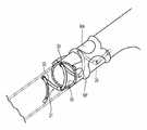
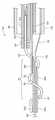
도 3a는 본 발명의 기술의 구현예에 따라 가이드 카테터와 함께 사용되는 신동맥 내에서 전달 상태(예를 들면 로우 프로파일 또는 접힌 배열)에 있는 카테터 샤프트의 전위 부분과 다중전극 어레이의 도면이다.
도 3b는 본 발명의 기술의 구현예에 따라 신동맥 내에서 전개된 상태(예를 들면 확장 배열)에 있는 도 3a의 카테터 샤프트의 전위 부분과 다중전극 어레이의 도면이다.
도 3c는 본 발명의 기술의 구현예에 따라 신동맥 내에서 전개된 상태에 있는 치료 장치의 등축도법의 부분 단면 모형도이다.
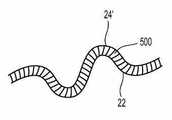
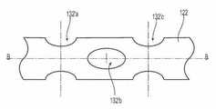
도 4a는 본 발명의 기술의 구현예에 따르는 치료 장치에서 사용하기 위한 치료 어셈블리의 평면도이다.
도 4b는 도 4a의 치료 어셈블리의 등축도이다.
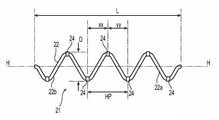
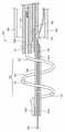
도 4c는 본 발명의 기술의 구현예에 따르는 치료 장치에서 에너지 전달 부재의 각도 오프셋(angular offset)을 나타내는 도 4b의 나선형 구조의 단면도이다.
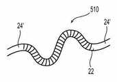
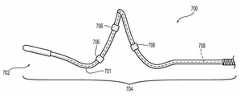
도 4d는 원주 방향으로 그리고 길이 방향으로 중첩되지만 나선형 경로를 따라 중첩되지 않는 치료 어셈블리에 의해서 예언적으로 형성된 병변을 갖는 베셀의 측면도이다.
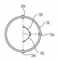
도 5a 내지 도 5d는 도 4a 및 도 4b의 치료 어셈블리와 함께 사용하기 위한 에너지 전달 부재 또는 장치의 각종 구현예를 나타낸다.
도 5e는 지지 구조가 전기 전도성이고 에너지 전달 부재의 역할을 하는 치료 어셈블리의 구현예를 나타낸다.
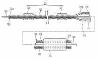
도 6a는 본 발명의 기술의 구현예에 따라 상이한 기계적 및 기능적 영역을 갖는 연장 샤프트를 포함하는 치료 장치의 구현예를 나타낸다.
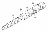
도 6b는 도 6a의 치료 장치에서 사용하기 위한 슬롯 패턴의 평면도이다.
도 6c는 본 발명의 기술의 구현예에 따라 환자 외부의 전달 상태(예를 들면 로우 프로파일 또는 접힌 배열)에서 도 6a의 치료 장치의 원위 부분의 투시도이다.
도 6d는 환자 외부의 전개된 상태(예를 들면 확장 배열)에서 도 6c의 치료 장치의 투시도이다.
도 6e는 일반적으로 나선형 형태의 전개된 상태에서 도 6a의 지지 구조의 원위 영역의 부분 개략 평면도이다.
도 6f는 본 발명의 기술의 구현예에 따라 다각형 형태의 전개된 상태에서 치료 장치의 원위 영역의 부분 개략 평면도이다.
도 6g는 본 발명의 기술의 다른 구현예에 따라 도 6a의 치료 장치에서 사용하기 위한 슬롯 패턴의 평면도이다.
도 6h는 본 발명의 기술의 다른 구현예에 따라 구성된 치료 장치에서 사용하기 위한 지지 구조의 투시도이다.
도 6i는 도 6h의 지지 구조에서 사용하기 위한 슬롯 패턴의 구현예의 평면도이다.
도 6j는 본 발명의 기술의 다른 구현예에 따라 구성된 치료 장치와 함께 사용하기 위한 슬롯 패턴의 평면도이다.
도 6k 및 도 6l은 전개된 상태에서 도 6h의 지지 구조의 변형된 슬롯을 나타낸다.
도 6m은 본 발명의 기술의 구현예에 따라 구성된 치료 장치와 함께 사용하기 위한 슬롯 패턴의 평면도이다.
도 6n은 본 발명의 기술의 구현예에 따라 구성된 치료 장치와 함께 사용하기 위한 슬롯 패턴의 평면도이다.
도 6o는 환자의 신동맥 내에서 전개된 상태에서 도 6N의 슬롯 패턴을 호함하는 지지 구조를 구비한 치료 장치의 일부분을 나타낸다.
도 7a는 본 발명의 기술의 구현예에 따라 구성된 치료 장치와 함께 사용하기 위한 홀 패턴의 평면도이다.
도 7b는 환자 외부의 전달 상태에서 도 7a의 홀 패턴을 갖는 플렉시블 영역을 포함하는 치료 장치의 원위 부분의 투시도이다.
도 8a는 본 발명의 기술의 구현예에 따라 구성된 도 6i의 슬롯 패턴을 포함하는 치료 장치의 부분 섹션에서 파단된 투시도이다.
도 8b 내지 도 8d는 본 발명의 기술의 구현예에 따라 구성된 지지 구조의 원위 단부의 각종 구성을 나타낸다.
도 9a는 환자 외부의 전개된 상태(예를 들면 확장된 구성)에서 본 발명의 구현예에 따라 구성된 치료 장치를 나타낸다.
도 9b는 전달 상태(예를 들면 로우 프로파일 또는 접힌 배열)에서 도 9a의 치료 장치를 나타낸다.
도 9c는 전개된 상태에서 본 발명의 기술의 구현예에 따라 구성된 치료 장치의 다른 구현예를 나타낸다.
도 9d는 전달 상태에서 치료 장치의 다른 구현예를 나타낸다.
도 9e는 전개된 상태에서 도 9d의 장치를 나타낸다.
도 10a는 본 발명의 기술의 구현예에 따라 환자 외부에서 전달 상태에서 다른 치료 장치의 파단된 평면도이다.
도 10b는 전개된 상태에서 도 10a의 장치의 원위 부분의 상세도이다.
도 11a는 본 발명의 기술의 다른 구현예에 따라 전달 상태에서 치료 장치의 부분 섹션에서의 파단된 측면도이다.
도 11b는 전개된 상태에서 도 11a의 치료 장치의 부분 섹션에서의 파단된 측면도이다.
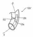
도 11c는 본 발명의 기술의 다른 구현예에 따라 도 11a의 장치에서 사용하기 위한 핸들 어셈블리의 길이 방향 횡단면도이다.
도 11d는 본 발명의 기술의 다른 구현예에 따라 도 11a의 장치에서 사용하기 위한 다른 핸들 어셈블리의 길이 방향 횡단면도이다.
도 12a는 본 발명의 기술의 구현예에 따라 환자 외부에서 전달 상태(예를 들면 확장된 구성)에서 치료 장치의 원위 부분의 측면도이다.
도 12b는 환자 외부에서 전달 상태(예를 들면 확장된 구성)에서 도 12b의 치료 장치의 원위 부분의 측면도이다.
도 13a는 본 발명의 기술의 구현예에 따라 전달 상태에서 치료 장치의 원위 부분의 파단된 측면도이다.
도 13b는 신동맥 내에서 전개된 상태에서 도 13a의 구현예의 부분 섹션의 파단된 측면도이다.
도 14a는 본 발명의 기술의 구현예에 따라 전달 상태에서 치료 장치의 다른 구현예의 길이 방향 횡단면도이다.
도 14b는 신동맥 내에서 전개된 상태에서 도 14a의 구현예의 부분 섹션의 파단된 측면도이다.
도 14c는 본 발명의 기술의 구현예에 따라 전달 상태에서 치료 장치의 다른 구현예의 원위 부분의 길이 방향 횡단면도이다.
도 14d는 신동맥 내에서 전개된 상태에서 도 14c의 구현예의 파단된 길이 방향 측면도이다.
도 15a는 본 발명의 기술의 구현예에 따라 전달 상태에서 치료 장치의 다른 구현예의 원위 부분의 길이 방향 횡단면도이다.
도 15b는 신동맥 내에서 전개된 상태에서 도 14a의 구현예의 부분 섹션에서 파단된 측면도이다.
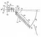
도 16a는 본 발명의 기술의 구현예에 따라 환자의 신동맥 내에서 전달 상태에서 치료 장치의 한 가지 구현예의 횡단면도이다.
도 16b는 본 발명의 기술의 구현예에 따라 환자의 신동맥 내에서 전개된 상태에서 치료 장치의 한 가지 구현예의 횡단면도이다.
도 17a는 본 발명의 기술의 구현예에 따라 구성된 속교환형 치료 장치의 원위 부분의 부분 섹션의 파단된 측면도이다.
도 17b는 본 발명의 기술의 구현예에 따라 전달 상태에서 속교환형 치료 장치의 원위 부분의 부분 섹션의 파단된 측면도이다.
도 17c는 전개된 상태에서 도 17B의 치료 장치의 원위 부분의 파단된 측면도이다.
도 17c는 본 발명의 기술의 구현예에 따르는 속교환형 치료 장치의 다른 구현예의 원위 부분의 부분 섹션의 파단된 측면도이다.
도 17d는 본 발명의 기술의 구현예에 따르는 속교환형 치료 장치의 다른 구현예의 원위 부분의 부분 섹션의 파단된 측면도이다.
도 17e는 본 발명의 기술의 구현예에 따르는 속교환형 치료 장치의 다른 구현예의 원위 부분의 부분 섹션의 파단된 측면도이다.
도 18은 본 발명의 기술의 구현예에 따르는 신동맥에서의 이론적 혈류를 나타낸다.
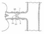
도 19a는 본 발명의 기술의 구현예에 따르는 신동맥 내에서 유체 방향전환 부재(fluid redirecting element)를 포함하는 치료 어셈블리의 단면도이다.
도 19b는 본 발명의 기술의 구현예에 따라 환자 외부에서 전달 상태(예를 들면 로우 파일 또는 접힌 구성)에서 유체 방향전환 부재의 개략적인 설명을 갖춘 지지 구조의 측면도이다.
도 20은 본 발명의 기술의 구현예에 따르는 도 1의 시스템과 함께 사용할 수 있는 에너지 전달 알고리즘을 나타내는 그래프이다.
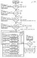
도 21 및 도 22는 본 발명의 기술의 구현예에 따라 치료를 평가하기 위한 알고리즘을 설명하는 블록 다이아그램이다.
도 23은 본 발명의 기술의 구현예에 따라 고온 조건의 발생하에 오퍼레이터 피드백을 제공하기 위한 알고리즘을 설명하는 블록 다이아그램이다.
도 24는 본 발명의 기술의 구현예에 따라 높은 임피던스 조건의 발생하에 오퍼레이터 피드백을 제공하기 위한 알고리즘을 설명하는 블록 다이아그램이다.
도 25는 본 발명의 기술의 구현예에 따라 고도의 베셀 수축의 발생하에 오퍼레이터 피드백을 제공하기 위한 알고리즘을 설명하는 블록 다이아그램이다.
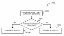
도 26a는 본 발명의 기술의 구현예에 따라 이상 심박수(abnormal heart rate) 조건의 발생하에 오퍼레이터 피드백을 제공하기 위한 알고리즘을 설명하는 블록 다이아그램이다.
도 26b는 본 발명의 기술의 구현예에 따라 낮은 혈류 조건의 발생하에 오퍼레이터 피드백을 제공하기 위한 알고리즘을 설명하는 블록 다이아그램이다.
도 27a 및 도 27b는 본 발명의 기술의 구현예에 따라 구성된 대표적인 제너레이터 디스플레이 스크린을 나타내는 스크린 샷이다.
도 28은 본 발명의 기술의 구현예에 따라 도 1의 패키지 성분을 포함하는 키트의 예시도이다.
도 29는 교감신경계의 개념적인 설명이며, 뇌가 어떻게 SNS를 통하여 신체에 전달하는지를 나타낸다.
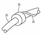
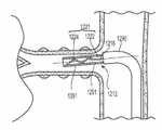
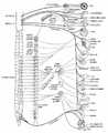
도 30은 좌측 신장을 자극하여 좌측 신동맥을 둘러싸는 신신경총(renal plexus)을 형성하는 신경의 확대된 해부도이다.
도 31a 및 도 31b는 뇌와 신장 간의 신경 원심성 및 구심성 정보교환(communication)을 나타내는 신체의 각각의 해부도 및 개략도이다.
도 32a 및 도 32b는 각각 인간의 동맥 및 정맥 맥관 구조의 해부도이다.Many aspects of the disclosure may be better understood with reference to the following figures. The components in the figures do not need to be changed in size. Instead, emphasis is placed on clearly describing the principles herein.
1 illustrates an vascular renal neuromodulation system constructed in accordance with embodiments of the present technology.
2 illustrates renal nerve regulation using a multielectrode catheter device in accordance with embodiments of the present technology.
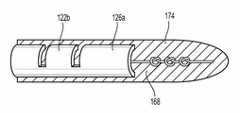
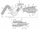
FIG. 3A is a diagram of the multielectrode array and the dislocation portion of the catheter shaft in a delivery state (eg, low profile or folded arrangement) within the renal artery used with a guide catheter in accordance with embodiments of the present technology.
FIG. 3B is a diagram of the multielectrode array and the dislocation portion of the catheter shaft of FIG. 3A in a deployed state (eg, an expanded arrangement) in the renal artery according to an embodiment of the present technology.
3C is a partial cross-sectional schematic view of an isometric view of a treatment device in a deployed state in the renal artery according to an embodiment of the present technology.
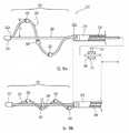
4A is a top view of a treatment assembly for use in a treatment device according to an embodiment of the present technology.
4B is an isometric view of the treatment assembly of FIG. 4A.
4C is a cross-sectional view of the helical structure of FIG. 4B showing the angular offset of the energy delivery member in the treatment device according to an embodiment of the technology of the present invention.
4D is a side view of the vessel with lesions formed prophetically by a therapeutic assembly that overlaps in the circumferential direction and in the longitudinal direction but does not overlap along the helical path.
5A-5D illustrate various embodiments of energy delivery members or devices for use with the treatment assemblies of FIGS. 4A and 4B.
5E illustrates an embodiment of a therapeutic assembly in which the support structure is electrically conductive and serves as an energy delivery member.
6A illustrates an embodiment of a treatment device that includes extension shafts having different mechanical and functional regions in accordance with embodiments of the present technology.
6B is a top view of a slot pattern for use in the treatment device of FIG. 6A.
6C is a perspective view of the distal portion of the treatment device of FIG. 6A in a delivery state outside the patient (eg, low profile or folded arrangement) in accordance with an embodiment of the present technology.
FIG. 6D is a perspective view of the treatment device of FIG. 6C in a deployed state (eg, an expanded arrangement) outside the patient.
FIG. 6E is a partial schematic plan view of the distal region of the support structure of FIG. 6A in a generally spirally deployed state. FIG.
6F is a partial schematic top view of the distal region of the treatment device in the polygonal deployed state according to an embodiment of the present technology.
FIG. 6G is a top view of a slot pattern for use in the treatment device of FIG. 6A in accordance with another embodiment of the technology of the present invention. FIG.
6H is a perspective view of a support structure for use in a treatment device constructed in accordance with another embodiment of the present technology.
6I is a top view of an embodiment of a slot pattern for use in the support structure of FIG. 6H.
6J is a top view of a slot pattern for use with a treatment device constructed in accordance with another embodiment of the technology of the present invention.
6K and 6L show a modified slot of the support structure of FIG. 6H in the deployed state.
6M is a top view of a slot pattern for use with a treatment device constructed in accordance with an embodiment of the present technology.
6N is a top view of a slot pattern for use with a treatment device constructed in accordance with an embodiment of the present technology.
FIG. 6O shows a portion of a treatment device having a support structure that incorporates the slot pattern of FIG. 6N in a deployed state in the renal artery of a patient.
7A is a top view of a hole pattern for use with a treatment device constructed in accordance with an embodiment of the present technology.
FIG. 7B is a perspective view of the distal portion of the treatment device including the flexible region having the hole pattern of FIG. 7A in a delivery state outside the patient. FIG.
8A is a perspective view broken in a partial section of the treatment device including the slot pattern of FIG. 6I constructed in accordance with an embodiment of the present technology.
8B-8D illustrate various configurations of the distal end of a support structure constructed in accordance with embodiments of the present technology.
9A shows a treatment device constructed in accordance with an embodiment of the present invention in a deployed state (eg in an expanded configuration) outside of a patient.
9B shows the treatment device of FIG. 9A in a delivery state (eg, low profile or folded arrangement).
9C shows another embodiment of a treatment device constructed in accordance with an embodiment of the present technology in the deployed state.
9D shows another embodiment of a treatment device in a delivery state.
9E shows the apparatus of FIG. 9D in the deployed state.
10A is a broken plan view of another treatment device in a delivery state outside a patient in accordance with an embodiment of the present technology.
10B is a detail view of the distal portion of the device of FIG. 10A in the deployed state.
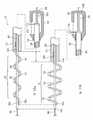
11A is a broken side view at a partial section of a treatment device in a delivery state, in accordance with another embodiment of the technology of the present invention.
FIG. 11B is a broken side view at a partial section of the treatment device of FIG. 11A in the deployed state.
FIG. 11C is a longitudinal cross sectional view of the handle assembly for use in the device of FIG. 11A in accordance with another embodiment of the present technology. FIG.
FIG. 11D is a longitudinal cross-sectional view of another handle assembly for use in the device of FIG. 11A in accordance with another embodiment of the present technology. FIG.
12A is a side view of the distal portion of a treatment device in a delivery state (eg, in an expanded configuration) outside a patient in accordance with an embodiment of the present technology.
12B is a side view of the distal portion of the treatment device of FIG. 12B in a delivery state (eg, in an expanded configuration) outside of the patient.
13A is a broken side view of the distal portion of a treatment device in a delivery state, in accordance with an embodiment of the present technology.
FIG. 13B is a broken side view of a partial section of the embodiment of FIG. 13A in a deployed state in the renal artery.
14A is a longitudinal cross-sectional view of another embodiment of a treatment device in a delivery state, in accordance with an embodiment of the technology of the present invention.
FIG. 14B is a broken side view of a partial section of the embodiment of FIG. 14A in a deployed state in the renal artery.
14C is a longitudinal cross-sectional view of the distal portion of another embodiment of the treatment device in a delivery state in accordance with an embodiment of the technology of the present invention.
FIG. 14D is a broken longitudinal side view of the embodiment of FIG. 14C in a deployed state in the renal artery. FIG.
15A is a longitudinal cross-sectional view of the distal portion of another embodiment of a treatment device in a delivery state in accordance with an embodiment of the technology of the present invention.
FIG. 15B is a side view broken in the partial section of the embodiment of FIG. 14A in a deployed state in the renal artery. FIG.
16A is a cross-sectional view of one embodiment of a treatment device in a delivered state within the renal artery of a patient in accordance with an embodiment of the present technology.
16B is a cross-sectional view of one embodiment of a treatment device in a deployed state in a renal artery of a patient in accordance with an embodiment of the present technology.
17A is a broken side view of a partial section of the distal portion of an rapid exchange treatment device configured according to an embodiment of the present technology.
FIG. 17B is a broken side view of a partial section of the distal portion of the rapid exchange treatment device in the delivery state in accordance with an embodiment of the technology of the present invention. FIG.
FIG. 17C is a broken side view of the distal portion of the treatment device of FIG. 17B in the deployed state.
FIG. 17C is a broken side view of a partial section of the distal portion of another embodiment of a fast-acting therapeutic device according to an embodiment of the present technology. FIG.
FIG. 17D is a broken side view of a partial section of the distal portion of another embodiment of a fast-acting therapeutic device according to an embodiment of the present technology. FIG.
FIG. 17E is a broken side view of a partial section of the distal portion of another embodiment of a fast-acting therapeutic device according to an embodiment of the present technology. FIG.
18 shows theoretical blood flow in the renal artery according to an embodiment of the present technology.
19A is a cross-sectional view of a treatment assembly including a fluid redirecting element in a renal artery according to an embodiment of the present technology.
FIG. 19B is a side view of a support structure with a schematic representation of a fluid redirecting member in a delivery state (eg, a low pile or folded configuration) outside a patient in accordance with an embodiment of the present technology. FIG.
20 is a graph illustrating an energy transfer algorithm that may be used with the system of FIG. 1 in accordance with an embodiment of the present technology.
21 and 22 are block diagrams illustrating algorithms for evaluating treatment in accordance with implementations of the techniques of this disclosure.
FIG. 23 is a block diagram illustrating an algorithm for providing operator feedback under the occurrence of a high temperature condition in accordance with an implementation of the disclosed technology.
24 is a block diagram illustrating an algorithm for providing operator feedback under the occurrence of a high impedance condition in accordance with an implementation of the disclosed technology.
25 is a block diagram illustrating an algorithm for providing operator feedback under occurrence of high vessel shrinkage in accordance with an embodiment of the present technology.
FIG. 26A is a block diagram illustrating an algorithm for providing operator feedback under occurrence of an abnormal heart rate condition in accordance with an implementation of the disclosed technology. FIG.
FIG. 26B is a block diagram illustrating an algorithm for providing operator feedback under the occurrence of low blood flow conditions in accordance with an embodiment of the present technology. FIG.
27A and 27B are screen shots illustrating an exemplary generator display screen constructed in accordance with an embodiment of the present technology.
FIG. 28 is an illustration of a kit including the package component of FIG. 1 in accordance with an embodiment of the technology of the present invention. FIG.
29 is a conceptual illustration of the sympathetic nervous system and shows how the brain transmits to the body via SNS.
30 is an enlarged anatomy of the nerve that stimulates the left kidney to form a renal plexus that surrounds the left renal artery.
31A and 31B are respective anatomical and schematic diagrams of the body showing neural centrifugal and afferent communication between the brain and kidneys.
32A and 32B are anatomical diagrams of human arterial and venous vasculature, respectively.
본 발명은 경피 경혈관 혈관내 접근을 통하여 전기적으로 유도되고/되거나 열적으로 유도된 신장 신경조절을 달성하기 위한 (신경을 자극하는 신경 섬유를 불활성화 또는 비활성하거나 완전히 또는 부분적으로 기능을 저하시키기 위한) 장치, 시스템 및 방법에 관한 것이다. 특히, 본 기술의 구현예는 전달 또는 로우 프로파일 상태(예를 들면, 일반적으로 직선 형태) 및 배치 상태(예를 들어, 방사상으로 확장된, 일반적으로 나선형 모양) 사이에 가동 가능한 다중 전극 어레이를 구비한 카테터를 도입하는 장치, 시스템 및 방법에 관한 것이다. 어레이에 의해서 전달되는 전극이나 에너지 전달 부재는 에너지(예를 들어, 전기 에너지, 고주파(RF) 전기 에너지, 전기 에너지, 열 에너지)를 경피 경혈관 경로(예를 들어, 대퇴 동맥 천자, 장골 동맥 및 대동맥, 요골 동맥, 또는 다른 적절한 혈관 통로)를 따라 카테터를 통해 신동맥에 전달하도록 구성된다. 다중 전극 어레이는, 어레이가 신동맥 내에 전개된 상태(예를 들면, 나선형)에 있을 때, 전극 또는 에너지 전달 부재가 신동맥의 내벽과 접촉하도록 하는 크기와 모양이다. 또한, 전개된 어레이의 나선형 모양은 혈액이 에너지 전달 부재의 활성화 중에 신동맥의 폐색을 방지하기 위해 예상되는 나선을 통해 흐를 수 있다. 또한, 어레이 안과 주변에서의 혈액의 흐름은 연결된 전극 및/또는 주변 조직을 냉각시킬 수 있다. 일부 구현예에 있어서, 에너지 전달 부재를 냉각시키는 냉각 없이 도달할 수 있는 것보다 낮은 온도에서 높은 전력 레벨의 전달을 가능하게 할 수 있다. 이러한 특징은 치료 동안 보다 깊고/깊거나 보다 큰 병변의 생성과 초기 표면 온도의 감소 및/또는 치료 중에 과열의 위험 감소와 더 긴 활성화 시간을 허용하도록 하는 데 도움이 되는 것으로 예상된다. 기술의 여러 가지 구현예의 구체적인 세부 사항은 도 1 내지 도 32b를 참조하여 아래에서 설명한다. 복수의 구현예가 그 설명 여기에 추가로 다중 전극 어레이를 사용하여 신장 신경을 혈관내 조절하는 장치, 시스템 및 방법에 대해 아래에 설명하지만, 본원 명세서에 기재된 것 이외의 다른 응용물 및 다른 구현예는 기술의 범위 내에 있다. 또한, 기술의 여러 가지 다른 구현예는 본원 명세서에 기재된 바와는 상이한 구성, 요소 또는 절차를 가질 수 있다. 따라서, 당업자는 기술이 추가의 요소를 갖는 다른 구현예를 가지거나, 기술은 도 1 내지 도 32b를 참조하여 아래에 설명되고 나타낸 복수의 특징 없이 다른 구현예를 가질 수 있다는 점을 이해한다.The present invention provides a method for inactivating or inactivating a nerve fiber that stimulates nerves or degrading function completely or partially to achieve electrically induced and / or thermally induced renal neuromodulation via a transdermal transvascular vascular endovascular approach. ) Apparatus, system and method. In particular, embodiments of the present technology include a multi-electrode array that is movable between a transfer or low profile state (eg, generally straight) and a placement state (eg, radially extended, generally spiral shaped). A device, system, and method for introducing a catheter. Electrodes or energy delivery members delivered by the array may be used to transfer energy (eg, electrical energy, radio frequency (RF) electrical energy, electrical energy, thermal energy) to the percutaneous transvascular vessel path (eg, femoral artery puncture, iliac artery and And through the catheter to the renal artery along the aorta, radial artery, or other appropriate vascular pathway. The multi-electrode array is sized and shaped to allow the electrode or energy transfer member to contact the inner wall of the renal artery when the array is in a deployed state (eg, a spiral) in the renal artery. In addition, the spiral shape of the deployed array may allow blood to flow through spirals that are expected to prevent occlusion of the renal artery during activation of the energy delivery member. In addition, the flow of blood in and around the array can cool the connected electrode and / or surrounding tissue. In some embodiments, it is possible to enable delivery of high power levels at lower temperatures than can be achieved without cooling to cool the energy delivery member. This feature is expected to help to create deeper and / or larger lesions during treatment and to reduce initial surface temperature and / or to reduce the risk of overheating during treatment and longer activation times. Specific details of various implementations of the technology are described below with reference to FIGS. 1-32B. While a plurality of embodiments are further described herein, devices, systems, and methods for endovascular control of renal nerve using multiple electrode arrays are described below, but other applications and other embodiments other than those described herein It is within the scope of the technology. In addition, various other embodiments of the technology can have different configurations, elements, or procedures than described herein. Thus, those skilled in the art understand that the technology may have other implementations with additional elements or that the technology may have other implementations without the plurality of features described and shown below with reference to FIGS.
본 명세서에서 사용하는 용어 "원위"와 "근위"는 치료하는 임상의 또는 임상의의 제어 장치(예를 들면, 핸들 어셈블리)에 대한 위치 또는 방향을 정의한다. "원위" 또는 "원위의"는 임상의 또는 임상의의 제어 장치로부터 먼 위치 또는 방향이다. "근위"와 "근위의"는 임상의 또는 임상의의 제어 장치 쪽으로 가까운 위치 또는 방향이다.
As used herein, the terms "distal" and "proximal" define the position or orientation of the treating clinician or clinician's control device (eg, a handle assembly). "Distal" or "distal" is a position or direction remote from the clinician or clinician's control device. "Proximal" and "proximal" are positions or directions close to the clinician or clinician's control device.
I. 신장 신경조절I. Kidney Neuroregulation
신장 신경조절은 신장을 자극하는 신경의 부분적 또는 완전 무력화 또는 기타 유효한 파괴이다. 특히, 신장 신경조절은 신장을 자극하는 신경 섬유(즉, 원심성 및/또는 구심성 신경 섬유)에 따라 신경 교신을 억제, 감소 및/또는 차단하는 것을 포함한다. 이러한 무력화는 장기간(예: 영구적이거나 또는 월, 년 또는 수십 년의 기간 동안) 또는 단기간(예를 들어, 분, 시간, 일 또는 주의 기간 동안)일 수 있다. 신장 신경조절은 증가된 전반적인 교감 활동을 특징으로 하는 몇몇 임상 조건과 고혈압, 심부전, 급성 심근 경색, 대사 증후군, 인슐린 저항성, 당뇨병, 좌심실 비대, 만성 말기 신장 질환, 심장 마비에서의 부적절한 유체 보존, 심장-신장 증후군 및 갑작스런 죽음 등의 자극을 통해 중추 교감과 관련된 특정 조건을 효과적으로 치료할 것으로 예상된다. 구심성 신경 신호의 감소는 교감신경 톤/드라이브의 전신 감소에 기여하고, 신장 신경조절은 조직의 교감을 통해 활동이나 과다활동과 관련된 몇 가지 조건을 치료하는 데 도움이 될 것으로 기대된다. 신장 신경조절 가능성이 교감신경에 의해서 자극받은 장기와 신체 구조의 다양한 혜택을 누릴 수 있다. 예를 들어, 중추 교감 드라이브의 감소는 대사 증후군 유형 II 당뇨병 환자를 괴롭히는 인슐린 저항을 줄일 수 있다. 또한, 골다공증을 호의적으로 활성화할 수 있으며, 신장 신경조절을 수반하는 교감 드라이브의 하방 제어(downregulation)로부터 혜택을 누릴 수 있다. 관련 환자의 해부학과 생리학에 대한 자세한 설명은 아래 섹션 IX에서 제공된다.Renal neuromodulation is a partial or complete neutralization or other effective disruption of the nerve stimulating the kidney. In particular, renal neuromodulation involves inhibiting, decreasing and / or blocking nerve communication according to nerve fibers (ie, centrifugal and / or afferent nerve fibers) that stimulate the kidney. Such neutralization can be long term (eg, permanent or for periods of months, years or decades) or short periods (eg, for periods of minutes, hours, days or weeks). Renal neuromodulation is associated with several clinical conditions characterized by increased overall sympathetic activity, hypertension, heart failure, acute myocardial infarction, metabolic syndrome, insulin resistance, diabetes, left ventricular hypertrophy, chronic terminal kidney disease, improper fluid retention in heart failure, heart Stimulation such as kidney syndrome and sudden death is expected to effectively treat certain conditions associated with central sympathy. Reduction of afferent nerve signals contributes to systemic reduction of sympathetic tone / drive, and renal neuromodulation is expected to help treat several conditions associated with activity or hyperactivity through tissue sympathy. Renal neuromodulation potential may benefit from various organ and body structures stimulated by sympathetic nerves. For example, a decrease in central sympathetic drive can reduce insulin resistance that plagues metabolic syndrome type II diabetic patients. It can also favorably activate osteoporosis and benefit from the downregulation of sympathetic drives involving renal neuromodulation. A detailed description of the anatomy and physiology of the patients involved is provided in section IX below.
다양한 기술이 신장을 자극하는 것과 같은 신경 경로를 부분적으로 또는 완전히 무력화하는 데 사용될 수 있다. 에너지(예를 들어, 전기 에너지, 열 에너지)를 에너지 전달 부재(들)에 의해서 조직에 목적 있게 적용함으로써 신동맥의 외막 내에서 긴밀하게 또는 인접하여 놓이는 신동맥의 지역화 영역과 신장 신경총 RP의 인접 지역에 대한 하나 이상의 원하는 열 가열 효과를 유도할 수 있다. 열 가열 효과의 목적 있는 적용으로 신경 조절이나 신장 신경총 RP의 전부 또는 일부를 따라 신경조절을 달성할 수 있다.Various techniques can be used to partially or completely neutralize neural pathways such as stimulating the kidneys. By applying energy (e.g., electrical energy, thermal energy) to the tissue by means of energy transfer member (s), the localized region of the renal artery, which is closely or contiguous within the outer membrane of the renal artery, and the adjacent region of the renal plexus RP One or more desired thermal heating effects can be induced. Purposeful application of the thermal heating effect can achieve neuromodulation or neuromodulation along all or part of the renal plexus RP.
열 가열 효과는 (예를 들어, 지속적인 가열 및/또는 저항 가열을 통해) 열 제거(therma ablation)와 비제거성 열 변형(non-ablative thermal alteration) 또는 병변 모두를 포함할 수 있다. 원하는 열 가열 효과는 원하는 임계값 이상의 표적 신경 섬유의 온도를 상승시켜 비제거성 열 변경을 달성하거나, 또는 높은 온도 이상으로 상승시켜 비제거성 열 변형을 달성하는 것을 포함할 수 있다. 예를 들어, 목표 온도는 체온 이상(예를 들면, 약 37℃) 또는, 비제거성 열 변형의 경우, 약 45℃ 미만일 수 있거나, 목표 온도는, 제거성 열 변형의 경우, 약 45℃ 이상일 수 있다.Thermal heating effects may include both thermal ablation and non-ablative thermal alteration or lesions (eg, through continuous heating and / or resistive heating). The desired thermal heating effect may include raising the temperature of the target nerve fiber above a desired threshold to achieve non-removable heat change, or rising above a high temperature to achieve non-removable heat deformation. For example, the target temperature may be above body temperature (eg, about 37 ° C.) or less than about 45 ° C. for non-removable thermal strain, or the target temperature may be about 45 ° C. or higher for removable thermal strain. have.
더 구체적으로, 약 37℃의 체온을 초과지만 약 45℃의 온도 이하의 열 에너지(가열)에 노출되면, 표적 신경 섬유의 적당한 가열을 통해 또는 표적 신경 섬유를 관류시키는 혈관 구조의 적당한 가열을 통해 열 변화를 유도할 수 있다. 혈관 구조가 영향을 받는 경우, 표적 신경 섬유는 신경 조직의 괴사로 인한 혈류가 거부된다. 예를 들어, 이는 섬유 또는 구조에서 비제거성 열 변형을 유도할 수 있다. 약 45℃, 또는 60℃ 이상의 온도 이상으로 가열에 노출시킴으로써 섬유 또는 구조의 실질적인 가열을 통해 열 변형을 유도할 수 있다. 예를 들어, 높은 온도는 표적 신경 섬유 또는 혈관 구조를 열적으로 제거할 수 있다. 일부 환자에 있어서, 표적 신경 섬유 또는 혈관 구조를 열적으로 제거하는 온도를 달성하는 것이 바람직할 수 있지만, 약 90℃ 미만, 또는 약 85℃ 미만 또는 약 80℃ 미만 및/또는 약 75℃ 미만일 수 있다. 열적 신경조절을 유도하는 데 사용되는 열 노출의 유형에 구애받지 않고 신장 교감신경 활동(RSNA)에서의 감소가 예상된다.
More specifically, when exposed to thermal energy (heating) above a body temperature of about 37 ° C. but below a temperature of about 45 ° C., through appropriate heating of the target nerve fiber or through proper heating of the vascular structure to perfuse the target nerve fiber. Thermal changes can be induced. If the vascular structure is affected, the target nerve fibers are rejected from the blood flow due to necrosis of the nerve tissue. For example, this can lead to non-removable thermal strains in the fiber or structure. Thermal deformation can be induced through substantial heating of the fiber or structure by exposure to heating above about 45 ° C., or above 60 ° C. For example, high temperatures can thermally remove target nerve fibers or vascular structures. In some patients, it may be desirable to achieve a temperature that thermally removes the target nerve fiber or vascular structure, but may be less than about 90 ° C., or less than about 85 ° C. or less than about 80 ° C. and / or less than about 75 ° C. . Regardless of the type of heat exposure used to induce thermal neuromodulation, a reduction in renal sympathetic activity (RSNA) is expected.
II. 다중전극 어레이를 구비한 카테터 장치의 선택된 구체예II. Selected Embodiments of Catheter Devices with Multielectrode Arrays
도 1은 본 기술의 구현예에 따라 구성된 신장 신경조절 시스템 10("시스템 10")을 나타낸다. 시스템 10은 작동 가능 에너지원 또는 에너지 발생기 26에 연결된 혈관 치료 장치 12를 포함한다. 도 1에 도시한 구현예에 있어서, 치료 장치 12(예를 들어, 카테터)는 근위 부분 18을 갖는 연장된 샤프트 16, 근위 부분 18의 인접 지역에 있는 핸들 34, 및 근위 부분 18에 대하여 원위로 뻗은 원위 부분 20을 포함한다. 치료 장치 12는 샤프트 16의 원위 부분 20에서 치료 어셈블리 또는 치료 섹션 21을 추가로 포함한다. 아래에서 추가로 자세하게 설명하는 바와 같이, 치료 어셈블리 21은 로우 프로파일 구성에서 신장 혈관(예를 들면, 신동맥)에 전달하도록 구성된 두 개 이상의 전극 또는 에너지 전달 부재 24의 어레이(array)를 포함할 수 있다. 신장 혈관 내에서 대상 치료 부위에 전달되면, 치료 어셈블리 21은 치료 현장에서 에너지를 전달하고 치료 효과적인 전기 및/또는 열 유도된신장 신경조절을 제공하기 위해 확장된 상태(예를 들면, 일반적으로 나선형 또는 스파이럴 구성)로 전개될 수 있도록 추가로 구성된다. 대안으로서, 전개 상태는, 전개 상태가 에너지를 치료 부위에 제공하는 비나선형일 수 있다. 몇몇 구현예에 있어서, 치료 어셈블리 21는 핸들 34에 의해서 운반되는 원격 액추에이션 예를 들면 노브, 핀 또는 레버 등의 액추에이터 36을 통해 전개 상태 또는 배열로 배치되거나 변환될 수 있다. 그러나, 다른 구현예에 있어서, 치료 어셈블리 21는 전달과 다른 적당한 기구나 기술을 사용하여 전개된 상태 사이에서 변환될 수 있다.1 illustrates renal neuromodulation system 10 (“
치료 어셈블리 21의 근위 단부는 연장된 샤프트 16의 근위 부분 20에 의해서 운반되거나, 이에 부착되어 있다. 치료 어셈블리 21의 원위 단부는 예를 들어, 비외상성 둥근 팁 또는 캡으로 치료 장치 12로 마무리지을 수 있다. 또한, 치료 어셈블리 21의 원위 단부는 시스템 10 또는 치료 장치 12의 또 다른 부재와 맞물리도록 구성할 수 있다. 예를 들어, 치료 어셈블리 21의 원위 단부는 오버-더-와이어 (over-the-wire; "OTW") 또는 신속한 교환("RX") 기술을 사용하여 치료 장치의 전달을 위한 가이드 와이어(미도시)와 체결되기 위한 통로를 정의할 수 있다. 이러한 배열에 관한 보다 자세한 사항은 도 9a 내지 도 17e를 참조하여 아래에서 설명한다.The proximal end of the
에너지원 또는 에너지 발생기 26(예를 들어, RF 에너지 발생기)는 에너지 전달 부재 24를 통해 대상 치료 부위로 배달을 위해 선택한 에너지의 형식과 크기를 생성하도록 구성된다. 에너지 발생기 26는 케이블 28를 통해 치료 장치 12에 전기적으로 결합할 수 있다. 적어도 하나의 공급 와이어(미도시)는 연장된 샤프트 16을 따라, 또는 연장된 샤프트 16 중의 루멘을 통하여 에너지 전달 부재 24를 통과하고, 치료 에너지를 에너지 전달 부재 24로 전달한다. 일부 구현예에 있어서, 각각의 에너지 전달 부재 24는 자체의 공급 와이어를 포함한다. 그러나, 다른 구현예에 있어서, 두 개 이상의 에너지 전달 부재 24는 동일한 공급 와이어에 전기적으로 결합할 수 있다. 풋 페달 32 등의 제어 메커니즘은, 오퍼레이터가, 이에 제한되지는 않지만, 동력 전달을 포함하는 발생기의 다양한 작동 특성을 개시, 종료,및 임의로 조정하도록 에너지 발생기 26에 (예를 들어, 공압 연결 또는 전기적으로 연결) 연결할 수 있다. 시스템 10은 무균 영역에 위치하여 에너지 전달 부재 24에 결합될 수 있는 원격 제어 장치(미도시)를 포함할 수도 있다. 원격 제어 장치는 전극을 선택적으로 턴 온/턴 옵 하도록 구성되어 있다. 다른 구현예에 있어서, 원격 제어 장치는 핸들 어셈블리 34에 내장될 수 있다. 에너지 발생기 26는 자동화 제어 알고리즘 30 및/또는 임상의의 통제하에 치료 에너지를 전달하도록 구성할 수 있다. 또한, 에너지 발생기 26은 치료 전, 치료 동안, 치료 후, 임상의에게 피드백을 제공하기 위해 하나 이상의 평가 또는 피드백 알고리즘 31을 포함할 수 있다. 적절한 제어 알고리즘 및 평가/피드백 알고리즘에 관한 자세한 사항은 도 20 내지 도 27을 참조하여 아래에 설명되어 있다.Energy source or energy generator 26 (eg, RF energy generator) is configured to generate the type and size of energy selected for delivery to the target treatment site via
몇몇 구현예에 있어서, 시스템 10은 에너지 전달 부재 24를 통하여 단극성 전기장의 전달을 제공하도록 구성될 수 있다. 이러한 구현예에 있어서, 중성 또는 분산성 전극 38은 에너지 발생기 26에 전기적으로 접속될 수 있고, (도 2에 도시되어 있는 바와 같이) 환자의 외부에 붙는다. 추가로, 하나 이상의 센서(미도시)[예를 들면, 아하 이상의 온도(예: 써모커플, 써미스터 등), 임피던스, 압력, 광학, 흐름, 화학 또는 기타 센서]는 에너지 전달 부재 24에 근접하여 배치되거나 에너지 전달 부재 24 내에서 배치되어 하나 이상의 공급 와이어(미도시)에 접속된다. 예를 들면 총 2개의 공급 와이어가 포함될 수 있는데, 두 와이어는 센서로부터의 신호를 전송하고, 하나의 와이어는 이중 목적을 제공하고 또한 에너지를 에너지 전달 부재 24로 전달한다. 대안으로서, 상이한 수의 공급 와이어를 사용하여 에너지를 에너지 전달 부재 24로 전송할 수 있다.In some embodiments,
에너지 발생기 26은 처리 회로(예: 마이크로프로세서)를 포함할 수 있는 장치 또는 모니터 및 디스플레이의 일부일 수 있다. 처리 회로는 제어 알고리즘 30과 관련된 저장된 지시를 실행하도록 구성될 수 있다. 모니터는 (예를 들면 케이블 28을 통하여) 치료 장치 12와 교신하여 전력을 에너지 전달 부재 24로 제어하고/하거나 에너지 전달 부재 24 또는 관련된 센서로부터 신호를 얻도록 구성될 수 있다. 모니터는 전력 수준 또는 센서 데이터(예: 음성, 시각 또는 기타 표시)의 지시를 제공하도록 구성되거나, 정보를 다른 장치에 전하도록 구성될 수 있다. 예를 들면 에너지 발생기 26은 치료 정보를 나타내는 카테터 랩 스크린 또는 시스템에 작동 가능하게 커플링되도록 구성될 수 있다.
도 2는 (도 30을 추가로 참고하면) 시스템 10의 구현예를 사용하는 신장 신경 조절을 나타낸다. 치료 장치 12는 혈관내 경로 P를 통하여 신신경총 RP에 대한 접속 예를 들면 대퇴부(도시됨), 팔, 요골 또는 액와동맥(axillary artery)에서의 경피 접속 부위을 개개의 신동맥 RA 내에서 표적 치료 부위에 제공한다. 도시되어 있는 바와 같이, 샤프트 16의 근위 부분 18의 섹션은 환자의 외부에 노출된다. 샤프트 16의 근위 부분 18을 혈관내 경로 P의 외부로부터 조작함으로써 임상의는 때때로 구불구불한 혈관내 경로 P를 통하여 샤프트 16을 나가게 하고 샤프트 16의 원위 부분 20을 원격 조작한다. 영상 안내 예를 들면 컴퓨터 단층촬영(CT), 투시검사, 혈관내 초음파(IVUS), 광간섭단층촬영(CCT), 또는 기타의 적합한 안내 양식, 또는 이들의 조합물을 사용하여 임상의의 조작을 보조할 수 있다. 추가로, 몇몇 구현예에 있어서, 영상 안내 성분(예를 들면, IVUS, OCT)을 치료 장치 12 자체 속으로 합체할 수 있다. 치료 어셈블리 21이 신동맥 RA 내에 적절하게 배치된 이후, 에너지 전달 부재 24가 신동맥 RA의 내부 벽과 안정하게 접촉할 때까지, 핸들 34 또는 기타의 적합한 수단을 이용하여 방사상으로 확장시키거나 또는 전개할 수 있다. 이어서, 에너지 전달 부재 24로부터의 에너지를 목적 있게 조직에 적용하여 신동맥의 국부화 영역과 신신경총 RP의 인접한 영역에 대한 하나 이상의 원하는 신경조절 효과를 유도하며, 이는 신동맥 RA의 외막 내에 긴밀하게, 인접하게 또는 가장 근위에 놓인다. 에너지를 목적 있게 적용함으로써 신신경총 RP 전체 또는 적어도 일부를 따라 신경조절을 달성할 수 있다.FIG. 2 illustrates renal neural regulation using an embodiment of system 10 (with further reference to FIG. 30).
신경조절 효과는 일반적으로 적어도 부분적으로 전력, 시간, 에너지 전달 부재 24와 혈관벽과의 접촉, 및 혈관을 통한 혈류의 기능이다. 신경조절 효과는 (예를 들면 지속적인 가열 및/또는 저항성 가열을 통하여) 신경차단, 열 제거, 및 비제거성 열 변경 또는 충격을 포함할 수 있다. 원하는 열 가열 효과는 표적 신경 섬유의 온도를 원하는 역치 이상으로 상승시켜 비제거성 열 변경을 달성하거나, 보다 높은 온도 이상으로 상승시켜 제거성 열 변경을 달성할 수 있다. 예를 들면, 표적 온도는, 비제거성 열 변경의 경우, 체온 이상(예를 들면 약 37℃) 약 45℃ 미만일 수 있거나, 표적 온도는, 제거성 열 변경의 경우, 약 45℃ 이상일 수 있다. 원하는 비열 신경조절 효과는 신경으로 전송된 전기 신호를 변경시키는 것을 포함한다.The neuromodulatory effect is generally at least partly a function of power, time, contact of the
몇몇 구현예에 있어서, 치료 어셈블리 21의 에너지 전달 부재 24는 지지 구조 22에 근접하거나, 인접하거나, 또는 이에 의해서 수행될 수 있다(예를 들면 접착되거나 스레드 오버되거나 감기거나 크림프된다). 지지 구조 22의 근위 단부는 커플링(미도시)을 통해 연장 샤프트 16의 원위 부분 20에 커플링되는 것이 바람직하다. 커플링은 연장 샤프트 16의 필요 불가결한 성분이거나(예를 들면 독립적인 피스가 아닐 수 있다), 커플링은 연장 샤프트 16의 외부 표면 주위을 감싸서 지지 구조 22를 연장 샤프트 16에 고정시키는 칼라(예를 들면 방사선 불투과성 밴드)와 같은 독립적인 피스일 수 있다. 그러나 다른 구현예에 있어서, 지지 구조 22는 다른 배열 및/또는 상이한 특징을 사용하는 연장 샤프트 16과 연관될 수 있다.In some embodiments, the
또 다른 구현예에 있어서, 에너지 전달 부재 24는 지지 구조 22 자체의 선택된 부분 또는 전처를 형성하거나 규정한다. 즉, 아래에서 추가로 설명하는 바와 같이, 지지 구조 22는 에너지를 전달할 수 있다. 게다가, 몇몇 구현예에서 치료 어셈블리 21은 단일 에너지 전달 부재를 사용하여 기능하지만, 치료 어셈블리 21은 지지 구조 22와 관련되거나 규정하는 복수의 에너지 전달 부재 24를 포함하는 것이 바람직하다는 것을 알 수 있다. 복수의 에너지 전달 부재 24가 제공되는 경우, 에너지 전달 부재 24는 독립적으로(즉, 단극성 유형으로 사용될 수 있다), 연속적으로, 선택적으로 또는 연속적으로 전력을 전달하고/하거나 원하는 조합의 부재들(즉, 쌍극성 유형으로 사용할 수 있다) 사이에 전력을 공급할 수 있다. 게다가, 임상의는, 각종 형태 또는 패턴을 갖는 신동맥 내에서 높게 지정된 병변을 형성하기 위해, 어느 에너지 전달 부재 24가 전력 전달에 사용되는지를 임의로 선택할 수 있다.In another embodiment, the
도 3a는 전달 상태(예를 들면 로우 프로파일 또는 접힌 구성)에서 신동맥 RA 내에서 샤프트 16과 치료 어셈블리 21의 원위 부분 20의 한 가지 구현예를 나타내는 단면도이고, 도 3b 및 도 3c는 전개된 상태(예를 들면 확장되거나 나선형 구성)에서 신동맥 RA 내에서 치료 어셈블리 21를 나타낸다. 우선 도 3a를 참조하면, 치료 어셈블리 21의 접힌 배열 또는 전달 배열은, 치료 어셈블리 21의 가로 방향 치수가 동맥 벽 55과 치료 장치 12 사이에 간격 거리(clearance distance)를 규정하기에 충분히 작도록 어셈블리의 종축 A-A에 대하여 낮은 프로파일을 정의한다. 전달 상태는 치료 장치 12의 삽입 및/또는 제거를 용이하게 하고, 경우에 따라, 신동맥 RA 내에서 치료 장치 12의 재설정을 용이하게 한다.3A is a cross-sectional view illustrating one embodiment of the
접힌 구성에 있어서 예를 들면 지지 구조체 22의 기하학은 신동맥 RA 내에서 치료 가이드 카테터 90을 통한 어셈블리 21의 치료 부위로의 움직임을 용이하게 한다. 게다가, 접힌 구성에 있어서, 치료 어셈블리 21은 신동맥 RA 내에서 맞도록 사이즈되고 형상화되며 신동맥 내부 직경 52보다 작은 직경과 신동맥 길이 54보다 작은 (치료 어셈블리 21의 근위 단부으로부터 치료 어셈블리 21의 원위 단부까지의 ) 길이를 갖는다. 또한, 아래에서 보다 더 상세하게 설명하는 바와 같이, 지지 구조체 22의 기하학은 신동맥 내부 직경 52보다 작은 중심 축 주위의 최소 가로 방향 치수와 신동맥 길이 54보다 바람직하게 작은 중심 축 방향의 최대 길이를 (전달 상태에서) 규정하도록 배열된다. 한 가지 구현예에 있어서, 예를 들면, 치료 어셈블리 21의 최소 직경은 연장 샤프트 16의 내부 직경에 대략 동등하다.In the folded configuration, for example, the geometry of the
샤프트 16의 원위 부분 20은 실질적인 방식으로 구부러져서 각각의 죄측/우측 신동맥으로 다시 들어간 다음, 가이드 카테터, 가이드 와이어 또는 쉬드(sheath)에 의해서 한정된 경로를 따른다. 예를 들면 원위 부분 20의 굽힘은 경피 삽입 부위로부터 신동맥 RA까지 가이드 카테터 90(예를 들면 원하는 경로를 따라 샤프트 16로 향하는 원위 단부 근처에서 예비형성된 벤드를 구비한 신장 가이드 카테터)에 의해서 부여될 수 있다. 다른 구현예에 있어서, 치료 장치 12는 신동맥 RA 속으로 삽입되어 경피 접속 부위로 뻗는 가이드 외이어(예를 들면 도 2의 가이드 외이어 66)를 체결하고 트래킹함으로써 신동맥 RA 내에서 치료 부위로 향할 수 있다. 시술에 있어서, 우선 가이드 와이어는 신동맥 RA 속으로 전달되는 것이 바람직하고, 이어서 가이드 와이어 루멘을 포함하는 연장 샤프트 16은 가이드 와이어를 너머 신동맥 RA 속으로 통과한다. 일부 가이드 와이어 치료에 있어서, (도 16a 및 도 16b를 참고하여 아래에서 보다 상세하게 설명하는) 관상 전달 쉬드 1291는 가이드 와이어(즉, 가이드 와이어 너머 전달 쉬드 슬라이드에 의해서 한정된 루멘)를 너머 신동맥 RA 속으로 통과한다. 일단 전달 쉬드 1291이 신동맥 RA에 놓이면, 가이드 외이어는 전달 쉬드 1291를 통하여 신동맥 RA 속으로 전달될 수 있는 치료 카테터(예를 들면 치료 장치 12)에 대하여 제거되어 교환될 수 있다. 또한, 몇몇 구현예에 있어서, 원위 부분 20은 예를 들면 작동 가능한 부재 36에 의해서 또는 다른 제어 부재에 의해서 핸들 어셈블리 34(도 1 및 도 2)를 통하여 신동맥 RA 속으로 향하거나 "스티어드(steered)"될 수 있다. 특히, 연장 샤프트 16의 굽힘은 전체가 본원 명세서에 참고로 삽입되어 있는 우(Wu) 등의 미국 특허출원 제12/545,648호[발명의 명칭: 정맥내 열 유도된 신장 신경조절을 달성하기 위한 장치, 시스템 및 방법(Apparatus, Systems, and Methods for achieving Intravascular, Thermally-Induced Renal Neuromodulation)]에 제공되어 있는 바와 같이 수행할 수 있다. 대안으로서, 또는 추가로, 치료 장치 12 및 이의 원위 부분 20은 가이드 카테터의 근위 단부으로부터 조종함으로써 조절하거나 재형상화될 수 있는 이의 원위 단부 근처에서 예비형성되거나 스티어링 가능한 벤드를 포함하는 스티어링 가능한 가이드 카테터(미도시)를 통하여 삽입됨으로써 구부러질 수 있다. 연장 샤프트 16과 치료 어셈블리 21의 에너지 전달 부재 24를 포함하여, 치료 장치 12의 섹션의 최대 외부 치수(즉, 직경)는 장치 12가 통과하는 가이드 카테터 90의 내부 직경에 의해서 한정될 수 있다. 한 가지 특수한 구현예에 있어서, 예를 들면 내부 직경이 약 0.091in(2.31mm)인 8 프렌치 가이드 카테터를 가이드 카테터로서 사용하여 신동맥에 접속할 수 있다. 에너지 전달 부재 24와 가이드 카테터 사이의 합리적인 허용 간격을 감안하면, 치료 어셈블리 21의 최대 외부 직경은 일반적으로 약 0.085in(2.16mm)보다 작거나 동등하다. 에너지 전달 부재 24를 운반하는 실질적인 나선형 지지 구조를 구비한 치료 어셈블리의 경우, 확장된 구성 또는 나선형 구성은 약 0.085 인치(2.16mm) 이하인 최대 폭을 한정한다. 그러나 보다 작은 5 프렌치 가이드 카테터를 사용하면 치료 장치 12를 따르는 더 작은 외부 직경을 사용하게 된다. 예를 들면, 5 프렌치 가이드 카테터 내에서 전송되는 나선형 지지 구조 22을 구비한 치료 어셈블리 21은 약 0.053in(1.35mm) 이하의 외부 치수 또는 최대 폭을 갖는다. 또 다른 구현예에 있어서, 치료 어셈블리 21은 실질적으로 0.053in(1.35mm) 이하의 최대 폭을 갖는 것이 바람직할 수 있으며, 다만 에너지 전달 부재와 가이드 카테터 사이의 간격은 충분하다. 게다가 일부 구현예에 있어서, 가이드 카테터와 치료 어셈블리 21은 약 1.5:1의 직경 비를 한정하는 배열을 갖는 것이 바람직할 수 있다. 다른 예에 있어서, 6 프렌치 가이드 카테터 내에서 전달될 나선형 구조와 에너지 전달 부재 24는 외부 치수가 0.070in(1.78mm) 이하이다. 추가의 예에 있어서, 기타의 적합한 가이드 카테터를 사용하고, 치료 장치 12의 외부 치수 및/또는 배열은 상응하게 변할 수 있다.The
치료 어셈블리 21을 신동맥 RA에서 샤프트 16의 원위 부분 20에 배치한 후, 치료 어셈블리 21은 전달 상태에서 전개된 상태 또는 전개된 배열로 전환된다. 변환은 특수한 구현예들과 이들의 각종 전개 모드에 대하여 본 명세서에서 설명한 바와 같은 장치 성분들의 배열을 이용하여 개시할 수 있다. 이하에서 보다 상세하게 설명하는 바와 같이, 그리고 본 기술의 하나 이상의 구현예에 따라, 치료 어셈블리는 변형력 또는 성형력을 어셈블리에 가하여 이를 전개된 상태로 변환시키기 위해 치료 어셈블리의 지지 구조과 내부적으로 또는 외부적으로 체결된 제어 부재(예를 들면, 풀 또는 텐션 와이어, 가이드 와이어, 샤프트 또는 스타일렛)에 의해서 전개될 수 있다. 대안으로서, 치료 어셈블리 21은, 방사상 억지력이 제거되어 어셈블리가 전개되도록 자체 확장하거나 전개될 수 있다. 치료 어셈블리 21을 전달 상태에서 전개 상태로 변형시키는 데 사용되는 양식은 대부분의 구현예에 있어서 반전되어 치료 어셈블리 21을 전개된 상태에서 전달 상태로 변환시킨다.After placing the
각각의 신동맥 RA 내에서 자자 구조 22과 에너지 전달 부재 24를 조작함으로써 각각의 신동맥 RA의 내부 벽을 따라 조직에 대하여 에너지 전달 부재 24의 동격관계(apposition)가 확립된다. 예를 들면 도 3b 및 도 3c에 도시되어 있는 바와 같이, 치료 어셈블리 21은 에너지 전달 부재 24가 신동맥 벽 55와 접촉하도록 신동맥 RA 내에서 확장한다. 몇몇 구현예에 있어서, 원위 부위 20의 조작은 에너지 전달 부재 24와 신동맥의 벽과의 접촉을 용이하게 한다. 본 명세서에 기재되어 있는 지지 구조(예를 들면 지지 구조 22)의 구현예는, 신동맥 내부 벽 55과 에너지 전달 부재 24간의 접촉력이 최대값을 초과하지 않도록 하는 것으로 기대된다. 게다가, 본 명세서에 기재되어 있는 지지 구조 또는 기타의 적절한 지지 구조는 일관된 병변 형성을 허용할 수 있는 동맥 벽 55에 대하여 일관된 접촉력을 제공하는 것이 바람직하다.By manipulating the
정렬은 동맥 벽 55 내에서 에너지 전달 부재 24의 기하학적 측면의 정렬을 포함할 수 있다. 예를 들면, 에너지 전달 부재 24가 말단이 둥근 실린더 형태를 갖는 구현예에 있어서, 정렬은 동맥 벽 55 내에서 개별적인 에너지 전달 부재 24의 세로 방향 표면의 정렬을 포함할 수 있다. 다른 예에 있어서, 구현예는 구조화된 형태 또는 비활성화 표면을 갖는 에너지 전달 부재 24를 포함할 수 있고, 정렬은, 구조화된 형태 또는 비활성화 표면이 동맥 벽 55와 접촉하지 않도록 에너지 전달 부재 24를 정렬하는 것을 포함한다.The alignment may include alignment of the geometric aspects of the
도 3b 및 도 3c에서 가장 잘 알 수 있는 바와 같이, 전개된 상태에 있어서, 치료 어셈블리 21은 나선형 경로를 따라 동맥 벽 55와 접촉하는 실질적인 나선형 지지 구조를 정의한다. 이러한 정렬의 한 가지 이점은 나선 구조로부터의 압력이 압력을 혈관 둘레에 적용하지 않고 대규모의 방사상 방향으로 적용할 수 있다는 점이다. 따라서 나선형으로 형성된 치료 어셈블리 21은, 벽이 어떤 방향으로 움직이는 경우, 에너지 전달 부재 24와 동맥 벽 55 사이의 안정한 접촉을 제공할 것으로 기대된다. 게다가, 나선형 경로를 따라 동맥 벽 55에 가해지는 압력은 벽 조직을 병변시킬 수 있는 벽 주위를 덜 늘어나게 하거나 확장시키는 것 같다. 확장된 나선 구조의 또 다른 특징은 혈관 벽을 대규모의 방사상 방향으로 접촉시킬 수 있고 충분하게 개방된 루멘을 혈관에서 유지하여, 치료 동안에 피가 나선 구조를 통하여 잘 흐르도록 한다는 점이다.As best seen in FIGS. 3B and 3C, in the deployed state,
도 3b에서 가장 잘 알 수 있는 바와 같이, 전개된 상태에 있어서, 지지 구조 22는 주요 신동맥의 신동맥 길이 54(즉, 분기점 가까이의 신동맥의 섹션)와 대략 동등하거나 작은 치료 어셈블리 21의 최대 축 길이를 규정한다. 이러한 길이는 환자마다 달라지기 때문에, 전개된 나선형 지지 구조 22는 상이한 환자에 대하여 적절할 수 있는 (예를 들면 도 4a에 도시한 바와 같이 다양한 길이 L 및/또는 직경 D를 갖는) 상이한 크기로 제작될 수 있는 것으로 상상된다. 도 3b 및 도 3c를 참고하면, 전개된 상태에 있어서, 나선형의 치료 어셈블리 21은 에너지 전달 부재 24와 신동맥 RA의 내부 벽 55 사이에 원주방향으로 불연속적인 접촉을 제공한다. 즉, 나선형 경로는 혈관벽의 종축에 대하여 혈관의 내부 벽을 따라 부분 호(arc)(즉, < 360°), 완전 호(즉, 360°), 또는 보다 완전한 호(즉, > 360°)를 포함할 수 있다. 그러나 몇몇 구현예에 있어서, 호는 동맥의 중심 축에 대하여 수직인 하나의 평면 내에 실질적으로 존재하지 않지만, 그 대신에 동맥의 중심 축과 함께 둔각(鈍角)을 규정하는 것이 바람직하다.
As best seen in FIG. 3B, in the deployed state, the
A. 나선 구조 (Helical Structure)A. Helical Structure
도 4a는 본 기술의 구현예에 따르는 치료 장치(예를 들면, 치료장치 12)와 함께 사용하기 위한 치료 어셈블리 또는 치료 어셈블리 21의 평면도이며, 도 4b는 도 4a의 치료 어셈블리 21의 등각도(isometric view)이다. 도 4a 및 도 4b에 나타낸 에너지 전달 부재 24는 단지 예시를 목적으로 하며, 치료 어셈블리 21은 상이한 수 및/또는 배열의 에너지 전달 부재 24를 포함할 수 있다.4A is a top view of a treatment assembly or
도 4a 및 도 4b에 도시한 바와 같이, 나선형은 전체 직경 D, 길이 L, 나선 각도 α(나선에 대한 접선과 이의 축 사이의 각도), 피치(HP: 이의 축에 평행하게 측정한 하나의 완벽한 나선 회선의 세로 방향 거리) 및 회전수(나선이 회전축에 대하여 360° 회전을 완료하는 횟수)를 적어도 부분적으로 특징으로 할 수 있다.As shown in FIGS. 4A and 4B, the spiral has a total diameter D, a length L, a helix angle α (the angle between the tangent to the helix and its axis), and a pitch (HP: one perfect measure parallel to its axis). The longitudinal distance of the spiral line) and the number of revolutions (the number of times the spiral completes a 360 ° rotation with respect to the axis of rotation).
특히 나선형의 전개되거나 확장된 구성은 자유 공간에서 신장 축을 따라 예를 들면 혈관 벽 또는 기타 구조에 의해서 제한받지 않고 이의 축 방향 길이 L을 특징으로 할 수 있다. 나선형 지지 구조 22가 이의 전달 상태로부터 방사상으로 확장함에 따라, 이의 직경 D는 증가하고 이의 길이 L은 감소된다. 즉, 나선 구조가 전개되는 경우, 원위 단부 22a는 축 방향으로 근위 단부 22b 쪽으로 (또는 그 반대로) 이동한다. 따라서, 전개된 길이 L은 확장되지 않은 길이 또는 전개 길이보다 작다. 어떤 구현예에 있어서, 지지 구조 22의 원위 단부 부분 22a 및 근위 단부 부분 22b 중의 하나만이 연장 샤프트 16 또는 이의 확장물에 견고하게 커플링된다. 다른 구현예에 있어서, 지지 구조 22는 원위 단부 부분 22a와 근위 단부 부분 22b를 서로에 대하여 트위스팅함으로써 이의 전개된 구성 또는 확장된 구성으로 변환시킬 수 있다.In particular, the spirally expanded or expanded configuration can be characterized by its axial length L along the elongation axis in free space, without being limited by, for example, vessel walls or other structures. As the
도 4b를 참고하면, 전개된 나선형 지지 구조 22는 비교적 직선이고 비외력성(예를 들면 둥근) 팁 50으로 말단처리될 수 있는 나선형 부분에 대하여 먼 쪽의 원위 연장부 26a를 임의로 포함한다. 팁 50을 포함하는 원위 연장부 26a는 나선 구조가 확장하고/하거나 전달 쉬드(delivery sheath)가 수축됨에 따라 혈관을 병변시키는 위험을 감소시킬 수 있으며, 나선 구조가 확장함에 따라 혈관에서의 나선 구조의 정렬을 용이하게 할 수 있다. 몇몇 구현예에 있어서, 원위 연장부 26a는 일반적으로 직선형이며(그러나 유연함), 길이가 약 40mm 미만(예를 들면, 2mm 내지 10mm)이다. 팁 50은 접착, 용접, 크림핑, 오버-몰딩 및/또는 납땜에 의해서 구조 부재의 말단에 고정되는 중합체 또는 금속으로 제조할 수 있다. 다른 구현예에 있어서, 팁 50은 구조 부재와 동일한 재료로 제조할 수 있으며, 기계가공하거나 용융시켜 팁 50으로 제작할 수 있다. 다른 구현예에 있어서, 원위 연장부 26a는 상이한 구성 및/또는 특징을 가질 수 있다. 예를 들면 몇몇 구현예에 있어서, 팁 50은 에너지 전달 부재 또는 방사선 불투과성 마커를 포함할 수 있다. 추가로, 원위 연장부 26a는 모든 구현예에 포함되지 않을 수 있는 임의의 특징이다.Referring to FIG. 4B, the deployed
나선 구조는 지지 구조 22의 나선형으로 형성된 영역에 비하여 비교적 직선인 근위 연장부 26b를 임의로 가질 수도 있다. 예를 들면 근위 연장부 26b는 지지 구조 22의 연장일 수 있고, 길이가 0mm 내지 40mm(예를 들면, 약 2mm 내지 10mm)일 수 있다. 대안으로서, 근위 연장부 26b는 지지 구조 22의 나머지보다 보다 더 유연한 개별적인 재료(예를 들면 중합체 섬유)로 구성될 수 있다. 근위 연장부 26b는 지지 구조 22의 나선형 영역과 연장 샤프트 16의 원위 단부 사이에 유연한 접속을 제공하도록 구성된다(도 1). 이러한 특징은 연장 샤프트 16으로부터 지지 구조 22의 나선형 영역으로 전달되는 힘을 감소시킴으로써 혈관 벽을 갖는 전개된 나선형 지지 구조 22의 정렬을 용이하게 하는 것으로 기대된다. 이는, 예를 들면 연장 샤프트가 혈관 벽의 한쪽으로 바이어스되는 경우, 또는 연장 샤프트가 혈관 벽에 대하여 이동하여 나선 구조가 위치를 유지하도록 한다면, 유용할 것이다.The spiral structure may optionally have a relatively straight
도 4a 및 도 4b로 돌아가 참고하면(그리고 도 3a 및 도 3b를 참고하면), 전개된 나선 구조 22의 치수는 이의 물리적 특징과 이의 구조(예를 들면, 확장된 : 확장되지 않은)에 의해서 영향을 받는데, 이는 차례로 신동맥 기하학을 염두에 두고 선택할 수 있다. 예를 들면 전개된 나선 구조 22의 축 방향 길이 L은 환자의 신동맥보다 길지 않도록 선택할 수 있다(예를 들면 도 3a 및 도 3b의 신동맥 RA의 길이 54). 예를 들면 접촉 부위와 신동맥의 소공(ostium) 사이의 거리(예를 들면 대퇴부 접촉 부위로부터 신동맥까지의 거리는 전형적으로 약 40cm 내지 약 55cm이다)는 신동맥의 길이를 따라 신정맥과 가장 먼 치료 부위로부터 신동맥의 길이보다 일반적으로 큰데, 이는 전형적으로 7cm 미만이다. 따라서, 연장 샤프트 16(도 1)는 적어도 40cm이고, 나선 구조는 이의 확장되지 않은 길이 L에 있어서 약 7cm 미만인 것으로 상상된다. 확장되지 않은 구성에서 약 4cm 이하의 길이가 대규모의 환자 집단에서 사용하기에 적합할 수 있고, 큰 접촉 면적을 제공하고, 확장된 구성에서의 경우, 그리고 몇몇 구현예에서 복수의 에너지 전달 부재를 설치하기 위한 긴 영역을 제공한다; 그러나 확장되지 않은 구성에서 보다 짧은 길이(예를 들면 약 2cm 미만)를 신동맥이 짧은 환자에게서 사용할 수 있다. 또한, 나선 구조 22는 전형적인 신동맥 직경으로 작업하도록 디자인될 수 있다. 예를 들면 신동맥 RA의 직경 52(도 3a)는 약 2mm 내지 약 10mm로 변할 수 있다. 특수한 구현예에 있어서, 나선 구조 22에서의 에너지 전달 부재 24의 설치는 신동맥 RA과 관련하여 신신경총 RP의 평가된 위치에 대하여 선택할 수 있다.Referring back to FIGS. 4A and 4B (and referring to FIGS. 3A and 3B), the dimensions of the unfolded
또 다른 특정한 구현예에 있어서, 구속받지 않은 구성으로 완전히 전개하도록 허용하는 경우(예를 들면, 도 4a 및 도 4b에서 도시한 바와 같은 본체를 제외하고), 치료 어셈블리 21의 섹션 또는 지지 구조는 약 15mm 미만(예를 들면 약 12mm, 10mm, 8mm, 또는 6mm)의 직경 D; 약 40mm 이하인(예를 들면 약 25mm 미만, 약 20mm 미만, 약 15mm 미만) 길이 L; 약 20° 내지 75°(예를 들면 약 35° 내지 55°)의 나선 각도 α; 0.25 내지 6(예를 들면 0.75 내지 2, 0.75 내지 1.25)의 회전 범위; 및 약 5mm 내지 20mm(예를 들면 약 7mm 내지 13mm)의 피치 HP를 갖는 나선형 형태를 포함한다. 다른 예에 있어서, 치료 어셈블리 21은, 중심 축 주위의 직경이 약10mm인 전달 상태에서 에너지 전달 부재 24가 동맥 벽과 접촉하는 전달 상태로 방사상으로 확장하도록 구성될 수 있다. 전술한 직경/각도는 기술의 특정한 구현예와 관련되며, 기술의 다른 구현예에 따라 구성된 치료 어셈블리는 상이한 배열 및/또는 구성을 가질 수 있다는 것을 알 수 있다.In another particular embodiment, where allowed to fully deploy in an unconstrained configuration (except for a body as shown in FIGS. 4A and 4B, for example), the section or support structure of the
몇몇 구현예에 있어서, 전개된 나선형 지지 구조 22는 일반적으로 원통형일 수 있다(즉, 나선형 직경은 이의 대부분의 길이를 따라 일반적으로 일정할 수 있다). 그러나 구조 22는 원뿔형의 나선형 형태, 테이퍼형의 구조 부재, 시계방향 또는 반시계방향 경로, 일정한 피치 또는 다양한 피치 등의 변형을 가질 수 있을 것으로 생각된다.In some embodiments, the unfolded
한 가지 구현예에 있어서, 지지 구조 22는 고형 구조 부재 예를 들면 와이어, 튜브, 코일형 케이블 또는 편조형 케이블을 포함할 수 있다. 지지 구조 22는 폴리에틸렌 테레프탈레이트(PET), 폴리아미드, 폴리이미드, 폴리에틸렌 블록 아미드 코폴리머, 폴리프로필렌, 또는 폴리에테르 에테르 케톤(PEEK) 등의 생체적합성 금속 및/또는 중합체로 형성될 수 있다. 몇몇 구현예에 있어서, 지지 구조 22는 비도전성, 도전성(예를 들면 스테인레스 강, 니티놀,은, 백금, 니켈-코발트-크롬-몰리브덴 합금) 또는 도전성 재료와 비도전성 재료와의 배합물일 수 있다. 한 가지 특수한 구현예에 있어서, 예를 들면 지지 구조 22는 스프링 템퍼 스테인레스 강 또는 니티놀 등의 예비성형재료로 형성될 수 있다. 추가로, 특수한 구현예에 있어서, 구조 22는, 치료 어셈블리 21이 신동맥 내에 적절하게 놓이고/놓이거나 전개되는 경우, 형광 투시법으로 영상화되어 임상의가 결정하도록 할 수 있는 방사선 불투과성 재료로 적어도 부분적으로 형성될 수 있다. 방사선 불투과성 재료는 예를 들면 황산바륨, 삼산화비스무스, 차탄산비스무스, 분말화 텅스텐, 분말화 탄탈, 또는 금과 백금을 포함하는 특정한 금속의 각종 제형을 포함할 수 있고, 이들 재료는 구조 부재 22에 직접 혼입되거나, 나선 구조 22 위의 부분 또는 완전 코팅물을 형성할 수 있다.In one embodiment, the
일반적으로, 나선 구조 22은, 삽입, 확장되어 신동맥 벽 55의 내부 표면과 접촉하는 경우, 원하는 외향 방사상 힘을 신동맥 벽 55(도 3a 및 도 3b)에 적용하도록 디자인될 수 있다. 방사상 힘은, 나선 구조 22가 환자 내에서 신동맥 벽 55에 대하여 확장하는 경우, 신동맥 RA의 스트레칭 또는 확장으로 인한 병변을 피하도록 선택할 수 있다. 신동맥 RA의 병변을 피할 수 있는 방사상 힘이 제공되고, 적절한 안정화 힘은 전형적인 혈압에 의해서 동맥 벽에 가해지는 방사상 힘을 계산함으로써 결정될 수 있다. 예를 들면, 적합한 방사상 힘은 약 300mN/mm 미만이거나 동등하다(예를 들면 200mN/mm 미만). 가해진 힘에 영향을 끼칠 수 있는 인자는 지지 구조 22의 기하학과 강인성이다. 한 가지 특수한 구현예에 있어서, 지지 구조 22는 직경이 약 0.003 내지 0.009in(0.08 내지 0.23mm)이다. 지지 구조 22의 조성에 따라, 구조 부재 직경은, 확장되는 경우, 신동맥에 대하여 원하는 일치성 및/또는 방사상 힘을 용이하게 하도록 선택할 수 있다. 예를 들면 강성 재료(예를 들면 금속)로 형성된 지지 구조 22는 유사한 굴곡성과 방사상 힘 프로파일을 달성하기 위해 매우 굴곡성인 중합체로부터 형성된 지지 구조 22와 관련하여 보다 얇을 수 있다. 나선형 지지 구조 22의 외향력은 관련된 압력 변환기에 의해서 체내에서 평가될 수 있다.In general, the
또한, 열처리와 어닐링을 포함하는 특정한 2차 공정은 섬유재료를 경화시키거나 연화시켜 강도와 강인성에 영향을 끼칠 수 있다. 특히, 니티놀과 같은 기억 형상 합금의 경우, 이러한 2차 공정은 동일한 출발 재료에 상이한 최종 물성을 부여하도록 변할 수 있다. 예를 들면 탄성 범위 또는 유연성은 증가하여 향상된 굴곡성을 부여할 수 있다. 기억 형상 합금의 2차 가공은 전이 온도, 즉 구조가 원하는 방사상 강도와 강인성을 나타내는 온도에 영향을 끼친다. 기억 형상 니티놀 등의 기억 형상 특성을 이용하는 구현예에 있어서, 이러한 전이온도는 정상적인 체온(예를 들면 약 37℃)에서 설정되거나, 약 37℃ 내지 45℃의 범위에서 설정될 수 있다. 초탄성 니티놀(super elastic nitinol)을 포함하는 다른 구현예에 있어서, 전이온도는 체온 이하, 예를 들면 0℃ 이하일 수 있다. 대안으로서, 나선 구조는 원하는 나선형 형태로 열적으로 엔지니어링되는 니티놀 등의 탄성 또는 초탄성 재료로 형성할 수 있다. 대안으로서, 나선 구조 22는 하나 이상의 중합체와 금속 등의 복수의 재료로 형성될 수 있다.In addition, certain secondary processes, including heat treatment and annealing, can harden or soften the fiber material and affect strength and toughness. In particular, for memory alloys such as Nitinol, this secondary process can be varied to give different final properties to the same starting material. For example, the elastic range or flexibility can be increased to impart improved flexibility. Secondary processing of the memory alloy affects the transition temperature, ie the temperature at which the structure exhibits the desired radial strength and toughness. In embodiments utilizing memory shape characteristics, such as memory shape nitinol, this transition temperature may be set at normal body temperature (eg, about 37 ° C.), or in the range of about 37 ° C. to 45 ° C. In another embodiment comprising super elastic nitinol, the transition temperature may be below body temperature, for example below 0 ° C. Alternatively, the spiral structure may be formed of an elastic or superelastic material, such as nitinol, which is thermally engineered into the desired spiral form. Alternatively,
도 3b 및 도 3c로 돌아가 참고하면, 치료 어셈블리 21의 지지 구조 22는, 환자에게 삽입되지 않는 경우, 전달 상태에서의 직경보다 큰 최대 직경으로 전개될 수 있음을 알아야 한다. 또한, 나선 구조 22는, 최대 직경이 신동맥 RA의 루멘 직경 52보다 크도록 제조할 수 있다. 그러나 환자에게 삽입되어 전개 상태로 변형되는 경우, 나선 구조 22는 방사상으로 확장하여 신동맥 루멘을 회전시키며, 이의 최대 원주 섹션에서 (예를 들면 에너지 전달 부재 24가 공간의 일부를 채우는 구현예에서) 신동맥 RA의 직경 52 보다 같거나 약간 작다. 과도한 병변 없이 소량의 관 확장이 야기될 수 있고, 구조 22는, 이의 최대 원주 섹션이 신동맥 RA의 직경 52보다 약간 더 크거나, 또는 하나 이상의 에너지 전달 부재 24가 신동맥 RA의 벽으로 약간 눌리도록 확장할 수 있다. 동맥 벽 55의 약간의 병변을 받지 않는 확장을 야기하는 나선형 어셈블리 또는 어레이는 에너지 전달 부재 24와 동맥 벽 55 사이에 안정한 접촉력을 유리하게 제공하고/하거나, 동맥이 호흡 운동과 혈류 펄싱으로 움직이는 바로 그 순간에 제자리에서 에너지 전달 부재 24를 유지할 수 있다. 신동맥 RA의 직경 52는 환자마다 달라지기 때문에, 치료 어셈블리 21은 전달 직경과 최대 직경 사이의 직경 범위를 추정할 수 있다.Referring back to FIGS. 3B and 3C, it should be appreciated that the
위에 제공된 바와 같이, 나선형 구성에서의 전개된 치료 어셈블리 21의 한 가지 특징은 나선 구조과 관련된 에너지 전달 부재 24가 혈관 벽과 안정하게 접촉하도록 배치되어 일정한 병변을 확실하게 생성할 수 있다는 점이다. 추가로, 다중 에너지 전달 부재 24는 목표 관 내에서 원하는 병변 구성을 달성하도록 적절한 공간을 갖고 나선 구조를 따라 배치될 수 있다. 위에서 설명한 나선형 구성을 갖는 치료 어셈블리의 여러 가지 구현예의 다른 특징은, 어셈블리가 상이한 관 직경의 비교적 넓은 범위 내에서 및/또는 각종 비틀림을 수반하여 적합하게 확장할 수 있다는 점이다.
As provided above, one feature of the deployed
B. 에너지 전달 부재의 크기와 구성B. Size and Composition of Energy Transfer Members
본원에 기술된 구현예들은 하나 이상의 에너지 전달 부재들 24와 함께 사용될 수 있다. 보다 상세하게 후술하는 바와 같이, 에너지 전달 부재들 24를 전달하는 전개된 나선형 구조는 재배치 설정 없이 치료 에너지를 신동맥으로 전달하도록 구성된다.Embodiments described herein can be used with one or more
에너지 전달 부재들 24의 예시적인 구현예들이 도 5a 내지 도 5d에 도시되었다. 나선형 구조 22와 관련된 에너지 전달 부재들 24은 나선형 구조 22의 분리 요소들이거나 일체로 된 부분일 수 있다. 어떤 환자들에서, 에너지 전달 부재(들) 24이 단일 병변 또는 신동맥 원주 둘레로 이격된 다중 국소 병변을 생성하도록 사용되는 것이 바람직하다. 소정의 종 방향 및/또는 원주 방향 치수들을 갖는 단일 국소 병변, 하나 이상의 일주(full-circle) 병변들, 공통의 종 방향에서 복수의 원주방향으로 이격된 국소 병변들, 나선형 병변들, 중단된 나선(interrupted spiral) 병변들, 선형 병변들 및/또는 공통의 원주 방향에서 복수의 종 방향으로 이격된 별개의 국소 병변들이 대안적으로 또는 추가적으로 생성될 수 있다. 다른 구현예들에서, 에너지 전달 부재들 24은 기타 다양한 기하학적 형상 또는 패턴들을 구비한 병변들을 생성하도록 사용될 수 있다.Exemplary embodiments of
에너지 전달 부재들 24의 크기, 형상 및 개수에 따라 형성된 병변들은 신동맥의 원주 둘레로 이격되고 동일하게 형성된 병변들이 신동맥의 종축을 따라 이격될 수 있다. 특정 구현예에서, 각각 형성된 병변들이 혈관 원주의 적어도 10%를 뒤덮어 신신경총에 영향을 미치는 가능성을 증가시키는 것이 바람직하다. 또한, 혈관의 근위단 또는 원위단에서 보이는 바와 같이 신장 신경 제거를 위해 형성된 병변 패턴을 신동맥의 원주 둘레의 모든 방향으로 적어도 대략적으로 연장시키는 것이 바람직하다. 즉, 각각의 형성된 병변은 원주의 원호를 뒤덮고 혈관 단부에서 보이는 바와 같이 각각의 병변들은 인접하거나 인접하여 중첩되거나 패턴 내의 다른 병변들은 실제 원주 병변 또는 가상의 원주 병변들을 생성한다. 실제 원주 병변을 규정하는 형성된 병변들은 신동맥의 종축에 대하여 수직인 단일 평면상에 존재한다. 하나 이상의 패턴의 병변들이 형성될 수 있다고 하더라도 가상의 원주 병변들은 단일 수직 평면에 존재하지 않는 다중 병변들에 의해서 규정된다. 가상의 원주 병변을 포함하는 하나 이상의 형성된 병변은 다른 병변들로부터 축 방향으로 이격된다. 비제한적인 예시에서, 가상의 원주 병변들은 신동맥을 따라 단일 나선 패턴으로 형성된 여섯 개의 병변들을 포함하여 각각의 병변은 혈관 원주의 적어도 1/6을 따라 연장되는 원호에 걸쳐지고 결과적인 병변의 패턴은 혈관 단부로부터 볼 때 혈관 원주를 완전히 둘러싼다. 다른 실시예에서, 가상의 원주 병변은 서로 다른 개수의 병변들을 포함할 수 있다. 또한, 각각의 병변이 혈관 외피 내부 및 밑으로 충분히 깊게 침투되어 신신경총에 영향을 주는 것이 바람직하다. 그러나, 너무 깊은(예를 들어, 5mm 초과) 병변은 비-타겟 조직 및 조직 구조들(예를 들어, 신정맥)을 방해하는 위험 요소를 가지기 때문에 에너지 치료의 깊이를 조절하는 것 또한 바람직하다.The lesions formed according to the size, shape and number of
도 4a 및 도 4b에 도시된 바와 같이, 에너지 전달 부재들 24는 나선형 구조 22상에 소정의 배열로 분포될 수 있다. 예를 들어, 애너지 전달 요소들 24 사이의 축 거리가 선택되어 신동맥 벽 55상에서 개별적인 에너지 전달 부재들 24에 의해서 형성된 병변의 가장자리가 중첩되거나 비-중첩된다. 축 거리 xx 또는 yy의 하나 또는 양자는 약 2mm 내지 1cm일 수 있다. 특정 구현예에서, 축 거리 xx 또는 yy는 약 2mm 내지 약 5mm의 범위일 수 있다. 다른 구현예에서, 에너지 전달 부재 24는 약 30mm 이격될 수 있다. 또 다른 구현예에서, 에너지 전달 부재 24는 약 11mm 이격될 수 있다. 또 다른 구현예에서, 에너지 전달 부재 24는 약 17.5mm 이격될 수 있다. 또한, 축 거리 xx는 축 거리 yy보다 더 작거나 동일하거나 더 클 수 있다.As shown in FIGS. 4A and 4B, the
에너지 전달 부재 24의 이격은 나선 이격 거리(helical length distance) zz에 의해서 특징지워지는데, 나선형 구조 22의 경로를 따른 에너지 전달 부재들 사이의 거리일 수 있다. 나선 이격 거리 zz는 에너지 전달 부재들 24에 의해서 생성된 병변의 크기에 기초하여 선택되어 병변들은 중첩되거나 중첩되지 않을 수 있다. 임의의 구현예들에서, 에너지 전달 부재들 24는 모두 다른 하나로부터 종방향 및 원주 방향으로 오프셋된다. 도 4c에 에너지 전달 부재들 24의 전개된 나선 구조 22의 원주 둘레로 다른 하나로부터의 각 오프셋 또는 분리를 보여주는 나선형 구조 22의 단면도가 예시적으로 도시되었다. 특히, 에너지 전달 부재 24c는 에너지 전달 부재 24a로부터 150° 오프셋되고 에너지 전달 부재 2b로부터 152° 오프셋된다. 에너지 전달 부재들 24a, 24b 및 24c를 통해 에너지가 신동맥에 인가될 때 오프셋 각들이 선택되어 병변들이 원주 방향으로 중첩되거나 중첩되지 않을 수 있다.The spacing of the
도 4d는 원주 방향으로 및/또는 종 방향으로 중복되지만 나선형 경로를 따라 중복되지 않는 병변(lesion)들 340이 형성된 혈관(vessel)의 측면도이다. 더욱 상세하게는, 병변들 340은 혈관(예를 들면, 도 4c) 및/또는 길이 방향 겹침부 342의 일 단부로부터 볼 때 원주방향 겹침부 341를 가지도록 에너지 전달 부재 24에 의해서 형성될 수 있지만, 나선형 길이 겹침부를 생성하지 않을 수 있으며 대신 나선형 길이 갭 343을 형성한다. 예를 들면, 에너지 전달 부재 24는 RF 에너지의 전기장을 혈관 벽으로 인가하기 위한 전극의 형태를 가질 수 있으며 약 6 내지 7mm의 나선 길이 방향에 의해서 이격된 전극들을 구비한 직경이 약 5mm가 되는 병변들을 발생하도록 구성될 수 있다. 에너지 전달 부재 24의 개수 및 위치에 따라, 임의의 적절한 회전수를 구비한 나선형 병변 패턴이 형성될 수 있다. 이와 같이 치료 장치 12는 복잡한 병변 패턴을 형성하도록 단일 에너지 인가를 채용할 수 있다. 도 4a 내지 도 4c에 도시된 구현예들이 예시적이고 사실상 개략적일 수 있으며, 서로 정확한 상관 관계가 없을 수 있으며, 방법의 소정의 양태들을 분류하기 위해서만 도시된다. 이와 같이, 에너지 전달 부재 24의 개수 및 간격은 도 4a 내지 도 4c의 각각에서 상이하며 예시된 구현예들에 의해서 형성된 병변들은 특히 재위치 설정 없이 취급 어셈블리 21의 단지 하나의 배치에서 에너지를 적용할 때, 위에서 설명된 수직 원주방향의 병변을 달성하도록 충분한 겹침 부분을 생성하지 않을 수 있다.4D is a side view of a vessel in which
도 3b를 다시 참조하면, 개별 에너지 전달 부재 24는 에너지 발생기 26(도 1)에 연결되고 신장 동맥의 내벽과 접촉하도록 하는 크기 및 형상을 가진다. 도시된 구현예에서, 에너지 전달 부재 24는 단극성(monopolar) 또는 이극성(unipolar) 모드로 작동될 수 있다. 이러한 배열에서, 인가된 RF 전기장에 대한 회수 경로가 예를 들면 또한 무관 전극 또는 중성 전극으로 지칭되는 외부 분산 전극(도 1 및 도 2에서 요소 38로서 도시된)에 의해서 설정된다. RF 전기장의 단극성 인가는 전극의 근처의 조직을 옴 방식(ohmically) 또는 저항 방식(resistively) 방식으로 가열하는 기능을 한다. RF 전기장의 인가는 조직을 열 병변시킨다. 치료 목적은 목표 중립 섬유들에서 신경조정술(예를 들면, 괴사, 열적 변화 또는 제거)을 열적으로 유도하는 것이다. 열적 병변은 혈관 벽에서의 병변을 형성한다. 대안적으로, RF 전기장에는 조직을 열적으로 병변시키지 않은 진동 또는 펄스 세기로 전달될 수 있고 이에 의해서 표적 신경들에서의 신경조정술은 신경 신호들의 전기적 변형에 의해서 달성된다.Referring again to FIG. 3B, the individual
에너지 전달 부재 24의 활성 표면적은 조직에 대해 밀접하게 접촉되게 배치될 수 있는 요소 24의 에너지 전달 영역으로서 형성된다. 에너지 전달 부재와 혈관 벽 사이의 매우 심한 접촉 영역은 조직과 에너지 전달 부재 사이의 경계부에서 또는 경계부 둘레에서 과도하게 높은 온도들을 생성할 수 있어, 이러한 경계부에서 과잉 열 발생을 형성한다. 이러한 과잉 열은 원주방향으로 매우 큰 병변을 생성할 수 있다. 이는 또한 혈관 벽으로의 바람직하지 않은 열 인가를 초래할 수 있다. 소정의 경우들에서, 너무 많은 접촉은 또한 작고, 얕은 병변들을 초래할 수 있다. 에너지 전달 부재와 혈관 벽 사이의 너무 적은 접촉은 혈관 벽의 표피 상의 가열을 초래할 수 있어, 매우 작고(예를 들면 혈관 외주의 < 10%) 및/또는 매우 얕은 병변을 생성한다.The active surface area of
에너지 전달 부재 24와 내부 혈관벽(예를 들면, 신장 동맥 벽 55) 사이의 접촉 표면적 ASA은 혈관 벽을 가로질러 열 에너지장의 발생의 효율 및 제어에 대한 큰 베어링을 가져서 신장 신경총에서 표적 중성 섬유들에 열적으로 영향을 미치도록 한다. 에너지 전달 부재의 ASA가 원하는 크기 및 깊이의 병변들을 생성하는 것이 중요하지만 , 전극 48 및 에너지 전달 부재 24의 ASA와 총 표면적(TSA) 사이의 비율이 또한 중요하다. ASA 대 TSA 비율은 다음의 두 가지 방식으로 병변 형성에 영향을 미칠 수 있다: (1) 전기장을 경유한 저항성 가열의 정도, 및 (2) 인젝트된 또는 인퓨즈된 식염수와 같은 혈액 유동 또는 다른 대류성 냉각 요소의 영향들. 예를 들면, RF 전기장은 전기장에 노출된 조직의 저항성 가열에는한 병변 형성을 유발한다. ASA 대 TSA 비율이 높을 수록(즉, 전극과 조직 사이의 접촉이 더 많을수록), 저항성 열들이 더 커진다, 예를 들면 형성되는 병변이 더 커진다. 아래에서 더 상세하게 논의되는 바와 같이, 전극(TSA-ASA)의 비접촉 부분에 대한 혈액의 유동은 전극의 전도성 및 대류성 냉각을 제공하며, 이에 의해서 혈관 벽과 전극 사이의 경계부로부터 떨어져 과잉 열 에너지를 운반한다. ASA 대 TSA의 비율이 너무 큰 경우(예를 들면, 50% 초과), 조직의 저항성 가열은 매우 어그레시브(aggressive)할 수 있지만 충분히 높은 과잉 열 에너지가 수행되지 않아서 과잉 열 발생 및 협착 부상, 혈전 형성 및 소망하지 않는 병변 크기에 대한 증가된 잠재성을 초래한다. ASA 대 TSA의 비율이 너무 낮은 경우(예를 들면, 10%), 이때 조직의 너무 작은 저항성 가열이 있어, 피상적인 가열 및 더 작고 더 얕은 병변들을 초래한다. 대표적인 일 구현예에서, 에너지 전달 부재 24의 ASP가 0.25 TSA ≤ ASA ≤ 0.50 TSA으로서 표현될 수 있다. 50% 이상의 ASA 대 TSA 비율은 여전히 감소된 전력 전달 알고리즘으로 보상함으로써 및/또는 전극을 혈액 흐름에 노출함으로써 전극의 대류성 냉각을 이용함으로써 과잉 열 발생 없이 유효할 수 있다. 아래에서 추가로 논의된 바와 같이, 전극 냉각은 전극 위로 그리고 혈액 스트림 내로 식염수(예를 들면 상온 식염수 또는 냉각 식염수)와 같은 냉각 액체들을 인젝팅하거나 인퓨징함으로써 달성될 수 있다.The contact surface area ASA between the
에너지 전달 부재 24에 대한 다양한 크기 제한들은 가이드 카테터의 최대 소망 치수들에는한, 뿐만 아니라 신장 동맥 루멘 자체의 크기 및 구조에는한 임상 이유들에 부과될 수 있다. 도 13 및 도 25에 도시된 구현예들과 같은 몇몇 구현예들에서, 에너지 전달 부재 24의 최대 외부 직경(또는 비-원형 횡단면에 대한 횡단면 치수)은 핸들 어셈블리 34에 대해 원위인 연장 샤프트 16의 길이를 따라 만나는 가장 큰 직경일 수 있다. 앞에서 설명된 바와 같이, 임상적 이유들 때문에, 에너지 전달 부재 24의 최대 외부 직경(또는 횡단면 치수)은 가이드 카테터의 최대 내부 직경에 의해서 제한되며 가이드 카테터를 통하여 연장 샤프트 16가 혈관내 경로 14를 통하여 지날 것이다. 8 프렌치 가이드 카테터(약 0.091in(2.31mm)의 내부 직경을 갖는)가 임상적 견해로부터 신장 동맥에 접근하기 위해 사용될 가장 큰 소망 카테터이며, 에너지 전달 부재 24와 가이트 카테터 사이의 타당한 제거 허용(clearance tolerance)을 허용하며 전극 46의 최대 직경은 약 0.085in(2.16mm)로 제한된다. 6 프렌치 가이드 카테터가 8 프렌치 가이드 카테터 대신 사용되는 경우, 이때 에너지 전달 부재 24는 최대 직경은 약 0.070 in(1.78mm), 예를 들면, 약 0.050in(1.27mm)로 제한된다. 5 프렌치 가이드 카테터가 사용된 경우, 이때 에너지 전달 부재 24의 최대 직경은 약 0.053in(1.35mm)로 제한된다.Various size restrictions on the
이러한 제한들 및 상술된 전력 전달 고려 사항들을 기초로 하여, 에너지 전달 부재 24는 약 0.049in 내지 약 0.051in(1.24mm 내지 1.30mm)의 외부 직경을 가질 수 있다. 에너지 전달 부재 24는 또한 약 0.020in(0.51mm)의 최소 외부 직경을 가질 수 있어서 충분한 냉각 및 병변 크기를 제공한다. 몇몇 구현예들에서, 에너지 전달 부재 24는 약 1mm 내지 약 3mm의 길이를 가질 수 있다. 에너지 전달 부재 24가 저항성 가열 요소인 몇몇 구현예들에서, 에너지 전달 부재 24는 약 0.049in 내지 0.051in(1.24mm 내지 1.30mm)의 최대 외부 직경 및 약 10mm 내지 30mm의 길이를 가진다. 에너지 전달 부재 24의 일 구현예가 예를 들면 지지 구조(예를 들면 관형 구조)을 중심으로 배치되는 4 내지 6개의 전극들의 다중 어레이를 위해 제공된다. 에너지 전달 부재 14은 예를 들면 금 전극들 또는 대안적으로 백금, 백금-이리듐, 또는 다른 적절한 재료일 수 있다. 하나의 특수한 구현예에서, 전극들은 약 0.030in 내부 직경(ID) × 0.0325in 외부 직경(OD) × 0.060in 길이(0.76mm × 0.83mm × 1.52mm)일 수 있다. 또 다른 특수한 구현예에서, 전극들은 0.029in ID × 0.033in OD × 0.060in 길이(0.72mm × 0.83mm × 1.52mm)일 수 있다. 또 다른 특수한 구현예에서, 전극들은 0.038in ID × 0.042in OD × 0.060in 길이 (0.97mm × 1.07mm × 1.52mm)일 수 있다. 또한, 전극들은 폴리머 내의 재킷 달린 전극들의 각각의 공급 와이퍼 어레이에 의해서 지지 구조로부터 적절히 전기 절연될 수 있어tj 지지 구조 22를 중심으로 컴팩트 패키지형 전극 어레이 어셈블리가 제공된다.Based on these limitations and the power transfer considerations described above, the
다른 구현예들에서, 치료 장치 12의 외부 직경은 하나 또는 둘 이상의 전달 부재 24에 의해서 한정될 수 있고 도 8a에 도시된 바와 같이 예를 들면 제어 와이어 168 와 같은 요소에 의해서 추가로 한정될 수 있다. 예를 들면, 특수한 구현예들은 8 프렌치 가이드 카테터가 사용될 수 있고 약 0.049in 내지 0.053in(1.24mm 내지 1.35mm)의 직경을 구비한 에너지 전달 부재 24 및 약 0.005in 내지 0.015in(0.13mm 내지 0.38mm)의 직경을 구비한 제어 와이어를 포함할 수 있다. 다른 구현예들에서, 그러나, 에너지 전달 부재 24 및/또는 제어 와이어의 배열 및/또는 치수들이 변화될 수 있다.In other embodiments, the outer diameter of the
소정의 구현예들에서, 나선 구조 22는 전기 전도성 재료로 형성될 수 있다. 예를 들면, 나선 구조 22는 니티놀 와이어, 케이블, 또는 튜브로 제조될 수 있다. 도 5e에 도시된 바와 같이, 와이어 리드들 19는 나선 구조 22를 에너지 발생기 26으로 연결할 수 있다. 나선 구조 22는 신장 동맥 벽을 구비한 접촉 영역을 형성하며 에너지 전달 부재 24로서 작용한다. 이러한 구성에서, 나선 구조 22는 연속 나선형 병변을 생성할 수 있다. 에너지 전달 부재 24가 선택적으로 나선 구조 22상에, 나선 구조 내에 및/또는 나선 구조 근처에 위치 설정되는 센서들 33을 포함할 수 있으며 공급 와이어 35에 전기적으로 연결될 수 있다.In certain implementations, the
다른 구현예들에서, 전기적으로 전도성 나선 구조 22는 적어도 부분적으로 절연된다. 즉, 전도성 나선 구조는 전기 전도성 재료로 부분적으로 덮혀지며 나선 구조 22의 덮혀지지 않은 부분들은 하나 또는 둘 이상의 전도성 에너지 전달 부재 24로서 기능한다. 에너지 전달 부재 24는 임의의 크기, 형상 또는 개수일 수 있고 본 명세서에서 제공된 바와 같이 서로에 대해 위치될 수 있다.In other embodiments, the electrically
에너지 전달 부재 24는 조직으로 열 에너지를 전달하도록, 즉 열 에너지가 조직을 가열하여 열 에너지를 조직으로 전도하도록 구성될 수 있다. 예를 들면, 에너지 전달 부재는 서미스터 또는 전기 전도성 와이어로 제조된 코일과 같은 전기 저항성 요소일 수 있어서 전류가 에너지 전달 부재를 통하여 지나갈 때 열이 생성된다. 전기 저항성 와이어는 예를 들면 예를 들면 48 내지 30 AWG의 직경을 구비한 니켈-크롬과 같은 합금일 수 있다. 저항성 와이어는 예를 들면 폴리이미드 에나멜에 의해서 전기 절연될 수 있다.The
소정의 구현예들에서, 에너지 전달 부재 24는 치료 동안 신장 동맥에 대해 각도방향으로 재위치 설정될 수 있다. 도 1 및 도 2를 다시 참조하면, 예를 들면, 이러한 각도방향 재위치 설정은 치료 어셈블리 21를 압축하고 핸들 어셈블리 34를 경유하여 치료 장치 12의 연장 샤프트 16를 회전시킴으로써 달성될 수 있다. 에너지 전달 부재 24의 각도 방향 또는 원주 방향 재위치 설정에 부가하여, 에너지 전달 부재 24는 선택적으로 또한 신장 동맥의 길이 방향 또는 종 방향 치수를 따라 재위치 설정될 수 있다. 이러한 종 방향 재위치 설정은 예를 들면 핸들 어셈블리 34를 경유하여 치료 장치 12의 연장 샤프트 16를 병진 운동시킴으로써 달성될 수 있고 에너지 전달 부재 24의 각도 방향 재위치 설정 전, 후 또는 동시에 발생할 수 있다. 도 3b를 참조하면, 종 방향 및 각도 방향 모두에서의 에너지 전달 부재 24의 재위치 설정은 신장 신경총 RP을 치료하기 위한 제2 치료 부위에서 신장 동맥의 내부 벽 55 과 접촉하게 에너지 전달 부재 24을 배치한다. 작동 중, 에너지가 이어서 이러한 제2 치료 부위에서 제2 초점 병변을 형성하도록 전기 전달 부재 24을 경유하여 전달될 수 있다. 다수 에너지 전달 부재 24가 나선 구조과 관련되는 구현예들에 대해, 초기 치료는 두 개 또는 세 개 이상의 병변들을 초래할 수 있고, 재위치 설정은 부가 병변들이 생성될 것을 허용할 수 있다.In certain embodiments,
소정의 구현예들에서, 나선형 지지 구조 22의 재위치 설정을 경유하여 생성된 병변들은 각각 신장 동맥 RA의 각도 방향 및 길이 방향 치수들을 중심으로 초기 병변(들)로부터 각도 방향 및 길이 방향으로 오프셋된다. 에너지 전달 부재(들) 24의 임의의 재위치 설정 후 초기 에너지 인가 및 모든 후속하는 에너지 인가들에는한 신장 동맥 RA을 따라 생성된 복합 병변 패턴은 불연속 병변을 효과적으로 초래할 수 있다(즉, 복수의 길이 방향 및 각도 방향으로 이격된 치료 부위들로 형성된다). In certain embodiments, lesions created via repositioning of the
대안적인 일 구현예에서, 에너지 전달 부재 24는 전기 전도성 와이어의 형태일 수 있다. 도 5d에 도시되어 있는 바와 같이, 예를 들면, 코일형 전극 24'을 형성하도록 나선 구조 22를 중심으로 전도성 와이어 500 가 감겨질 수 있다. 코일형 전극 24'은 에너지를 전달하기 위한 증가된 표면적을 제공할 수 있다. 예를 들면, 코일형 전극 24'은 단일 에너지 인가에서 일반적으로 연속 나선형 병변을 형성할 수 있다. 코일형 전극 24'은 원하는 병변에 따라, 나선 구조 22를 중심으로 임의의 방식으로 권취될 수 있다. 예를 들면, 코일형 전극 24'은 나선의 길이를 따라 연속 경로를 형성할 수 있거나 코일식 구조는 비전도성 섹션들에 의해서 분리된 하나 또는 둘 이상의 짧은 별개의 전극들을 형성할 수 있다. 다른 구현예들에서, 나선 구조가 확장할 때 혈관 벽과 접촉하도록 코일형 전극 24'의 부분들이 나선 구조 상에 위치될 수 있으며, 반면 나선 구조가 병변들이 불연속되는 것을 허용하도록 확장될 때 혈관 벽으로부터 떨어져 코일식 전극 24'의 다른 부분들이 위치 설정될 수 있다. 또한, 이 같은 일 배열체에서, 신장 동맥과 접촉하지 않는 코일형 전극 24'의 영역들은 아래에서 더 상세히 설명되는 바와 같이, 에너지 전달 부재 24'의 냉각에 기여할 수 있다. 에너지 전달 부재 24'을 형성하는 전도성 부분들의 위치설정 및 개수가 원하는 병변 패턴에 따라 선택될 수 있다.In an alternative embodiment,
도 5a 및 도 5b에 도시된 구현예들에서, 에너지 전달 부재 24는 바람직하게는 원형 단부 및 루멘을 구비한 금속 전극들을 포함한다. 니티놀 나선형 지지 구조 22는 바람직하게는 전기적으로 절연되고(예를 들면 PET를 이용하여) 전극들 24는 절연체 위에 장착된다. 공급 와이어 25는 전극을 에너지 공급원(미도시)에 연결하고 에너지(예를 들면 RF 전류)를 전극 24에 전달한다. 라운드형 단부들은 혈관 벽에 대한 기계적 자극을 감소시키고 에너지가 전달될 때 전극들과 비교된 더 일치하는 전류 밀도를 사각 또는 더 날카로운 단부들을 구비한 전극들에 제공된다. 에너지 전달 부재 24는 대안적으로 언급된 바와 같이 도 5d를 참조하여 위에서 설명된 코일 전극 24'와 같은 다른 형태들을 포함할 수 있다. 다른 구현예에서, 나선형 구조 22를 형성하는 구조적 요소 510은 도 5c에서 예시적으로 도시된 바와 같이 에너지 전달 부재 24' 자체일 수 있다.
In the embodiments shown in FIGS. 5A and 5B, the
III. 신장 신경 제거 시스템들의 선택된 구현예들III. Selected Embodiments of Renal Nerve Removal Systems
본 명세서에 제공된 대표적인 구현예들은 서로 조합될 수 있고 다른 공개된 구현예들의 특징들을 구비한 특징들을 포함한다. 이러한 구현예들의 간결한 설명을 제공하도록, 실제 실행의 모든 특징들이 명세서에서 설명되지 않는다. 임의의 이 같은 실제 실행의 개선에서 설계 프로젝트 또는 임의의 공학에서, 다양한 실행-특성 결정들이 하나의 실행으로부터 다른 실행으로 변화될 수 있는, 시스템 관련 및 사업 관련 구속들의 준수와 같은 개발자들의 특정 목적들을 달성될 수 있어야 한다는 것을 이해하여야 한다.Representative embodiments provided herein include features that may be combined with one another and that include the features of other published embodiments. In order to provide a concise description of these implementations, not all features of an actual implementation are described in the specification. In any such improvement in actual practice, in a design project or in any engineering, the developer's specific goals, such as compliance with system-related and business-related constraints, may vary from one implementation to another. It should be understood that it should be achievable.
도 6a는 방법의 일 구현예에 따라 구성된 상이한 기계적 및 기능적 영역들을 가지는 연장 샤프트 116를 포함하는 치료 장치 112의 일 구현예를 도시한다. 치료 장치 112의 연장 샤프트 116은, 예를 들면 치료를 위한, 특히 신장 신경 제거를 위한 신장 동맥 부위에서 전달 및 전개를 위해 치료 또는 치료 어셈블리 121를 구비한 원위 영역을 포함한다. 연장 샤프트 116의 원위 단부에 배치된 것은 연장 샤프트 116 및 치료 어셈블리 121의 조종을 위한 핸들 어셈블리 134이다. 더욱 상세하게는, 핸들 어셈블리 134는 전달 상태와 전개 상태 사이의 치료 어셈블리 121를 제어하거나 변형하기 위한 제어 부재(예를 들면, 도 6e 또는 도 8a)의 원격 작동을 위해 제공하도록 액추에이터 136(개략적으로 도시됨)으로 구성된다. 적절한 핸들 어셈블리들에 관한 추가의 상세들은 예를 들면 클라크(Clark) 등의 미국 특허출원 제12/759,641호[발명의 명칭: 혈관 내 치료 장치들을 위한 핸들 어셈블리들 및 관련 시스템들 및 방법들]에 기재되어 있으며 이 출원은 전체적으로 인용에 의해서 본 발명에 포함된다.6A illustrates one embodiment of
치료 장치 112는 어셈블리 121가 실질적으로 선형인(예를 들면, 직선형) 전달(예를 들면, 로우 프로파일) 상태에서 치료 부위로 치료 어셈블리 121을 전달하도록 구성되어 치료 어셈블리 121의 지지 구조 122에 의해서 지지되는 에너지 전달 부재(미도시)은 지지 부재 122를 따라 실질적으로 축 방향으로 정렬된다. 신장 동맥 내의 치료 부위에 위치되면, 핸들 어셈블리 134는 치료 어셈블리 121을 전달 상태로부터 전개 상태로 변환하는 제어 부재의 작동을 위해 작동된다. 일 구현예에서, 예를 들면, 제어 부재가 관형 지지 구조 122의 내부 루멘 내에 배치되는 제어 와이어 168(도 8a)를 포함한다. 제어 와이어 168의 일 단부는 지지 구조 122의 원위 단부에 또는 근처에 부착될 수 있고 제어 와이어 168의 대향 단부는 핸들 어셈블리 134 내에서 종결된다. 앞에서 언급된 바와 같이, 핸들 어셈블리 134는 전달 및 전개 상태들 사이에서 치료 어셈블리 121를 변형하도록 제어 와이어 168를 조종하기 위해 구성된다. 제어 와이어 168에서의 인장은 지지 구조 122상에 작용하는 근위 및 축 방향 지향력을 위해 제공된다. 제어 와이어 168에서 인장력의 영향 하에서 그리고 혼자의 신장 동맥 벽의 방사상 구속의 영향 하에서 환자 내에서 작동시 지지 구조 122는 에너지 전달 부재를 신장 동맥의 벽과 안정되게 접촉하도록 나선형 기하학적 형상 내로 전개하도록 변형된다.The
전개시 원하는 변형을 위해 제공하도록, 지지 구조 122는 지지 구조 122를 중심으로 선택적으로 형성되거나 배치되는 복수의 슬롯들, 절단부들, 관통 구멍들 및/또는 개구들을 가지는 관형 부재일 수 있다. 관형 지지 구조 122는 위에서 설명된 지지 구조 22의 특징들에 일반적으로 유사한 복수의 특징들을 가질 수 있다. 예를 들면, 지지 구조 122는 PET, 폴리아미드, 폴리이미드, 폴리에틸렌 블록 아미드 코폴리머, 폴리프로필렌, 또는 PEEK 폴리머를 포함하는 생체 적합성 금속들 및/또는 폴리머로 형성될 수 있으며 슬롯들은 원하는 형상들로 관형 구조 내로 바람직하게는 레이저 커트된다. 특수한 구현예들에서, 지지 구조 122는 비도전성, 도전성(예를 들면, 스테인레스 강, 니티놀,은, 백금 니켈-코발트-크롬-몰리브덴 합금), 또는 도전성 및 비도전성 재료들의 조합일 수 있다. 하나의 특수한 구현예에서, 지지 구조 122는 스프링 템퍼 스테인레스 강 또는 니티놀과 같은 예비성형된 재료로 형성될 수 있다. 더욱이, 몇몇 구현예들에서 지지 구조 122는 임상의가 지지 구조 122가 적절하게 배치되고/되거나 신장 동맥 내에서 전개되는 경우를 결정하는 것을 허용하기 위해 형광 투시법으로 영상화될 수 있는 방사선 불투과성 재료들로부터 적어도 부분적으로 형성될 수 있다. 방사선 불투과성 재료들은 황산바륨, 삼산화비스무스, 차탄산비스무스, 분말형 텅스텐, 분말형 탄탈, 또는 금, 백금, 및 백금-이리듐을 포함하는 소정의 금속들의 다양한 제형을 포함할 수 있으며, 이러한 재료들은 지지 구조 122 내로 직접 통합될 수 있거나 지지 구조 122의 부분적 또는 완전한 코팅을 형성할 수 있다.The
지지 구조 122를 주심으로 형성되거나 배치된 슬롯들, 커트들, 관통 구멍들, 및/또는 개구들의 위치, 배향 및/또는 구성은 구조의 변형을 한정한다. 또한, 슬롯들, 커트들, 관통 구멍들, 및/또는 개구들은 관형 구조 122를 따라 변화되어 구조를 따라 변형의 가변 영역들을 한정한다. 도 6a에 도시된 구현예에서, 예를 들면, 관형 구조 122는 원위 변형 영역 122a, 원위 변형 영역 122a에 근접한 중간 오리엔테이션 영역, 및 오리엔테이션 영역 122b에 근접한 전이 또는 플렉서블 영역 122c을 포함한다. 아래에서 더 상세히 설명될 바와 같이, 디플렉션 영역 122a는 전개시 실질적으로 나선형 기하학적 형상을 가지도록 구성된다. 오리엔테이션 영역 122b는 신장 동맥의 벽을 향하여 그리고 연장 샤프트 116의 길이 방향 축선 B로부터 떨어져 디플렉션 영역 122a를 위치하도록 또는 편향되도록 구성된다. 연장 샤프트 122가 때때로 경피 접근 부위로부터 각각의 신장 동맥 내의 표적 처리 부위로 구불구불한 혈관 내 경로를 통하여 전진할 때 전이 영역 122c은 치료 장치 122에 플렉서블을 제공하도록 한다(도 2를 참조하여 위에서 설명된 바와 같이). 또한 치료 장치 112의 상이한 영역들의 기계적 및 기능적 양태들에 대한 추가의 상세가 아래 설명된다.The location, orientation, and / or configuration of the slots, cuts, through holes, and / or openings formed or arranged around the
도 6b는 방법의 일 구현예에 따라 구성된 슬롯 패턴의 평면도이다. 도 6a 및 도 6b를 함께 참조하면, 예를 들면, 디플렉션 영역 122a는 스파이럴 방식으로 지지 구조 122를 따라 배열된 복수의 실질적으로 동일한 길이 횡방향 슬롯들 128에 의해서 형성될 수 있다. 오리엔테이션 영역 122b는 복수의 축 방향으로 이격된 횡방향 슬롯들 130에 의해서 한정될 수 있으며 이 슬롯들 내에 두 개 이상의 슬롯들이 길이가 상이하다. 또한, 도 6a에서 최상으로 도시된 바와 같이, 오리엔테이션 영역 122b는 디플렉션 영역 122a보다 더 작은 축 방향 길이를 가질 수 있다. 전이 영역 122c은 오리엔테이션 영역 122b의 근위에 위치되며 디플렉션 영역 122a 및 오리엔테이션 영역 122b 각각 보다 더 큰 축 방향 길이를 가진다. 예시된 구현예에서, 전이 영역 122c은 지지 구조 122를 따라 변화하는 피치를 가지는 연속 스파이럴 커트 또는 슬릿 132을 포함할 수 있다. 일 구현예에서, 예를 들면 스파이럴 커트 132의 피치는 연장 샤프트 116을 따라 근위에서 증가할 수 있다. 또한 치료 장치 112의 영역들의 다양한 기계적 및 기능적 양태들에 대한 상세한 내용이 아래에 설명된다.6B is a top view of a slot pattern constructed according to one embodiment of the method. 6A and 6B, for example, the
도 6c는 본 방법의 구현예에 따라 환자의 외부의 전달 상태(예를 들면 로우 프로파일 또는 접혀진 구성)에서 지지 구조 122을 포함하는 치료 장치 122의 사시도이며, 도 6d는 전개된 상태(예를 들면 확장된 구성)에서 지지 구조 122의 사시도이다. 용이한 이해를 위해, 도 6c 및 도 6d에서 지지 구조 122는 지지 구조 122를 중심으로 배치된 에너지 전달 부재 없이 도시된다.FIG. 6C is a perspective view of
도 6c 및 도 6d를 함께 참조하면, 지지 구조 122는 종방향 축선 B-B를 한정하도록 중심 루멘을 가지는 관형 부재를 포함한다. 위에서 설명된 바와 같이, 지지 구조 122는 기부의 일반적인 플렉서블 변이 영역 122c, 중간 오리엔테이션 영역 122b, 및 원위 디플렉션 영역 122a을 포함한다. 지지 구조 122는 원위 디플렉션 영역 122a 및 중간 오리엔테이션 영역 122b을 변형하도록 근위 지향 축 방향 성분을 가지고 바람직하게는 원위 단부 126a에서 그리고 원위 단부 126a 근처에 인가된 힘의 인가에 의해서 전달 상태(도 6c)와 전개 상태(도 6d) 사이에서 선택적으로 변형가능하다. 일 구현예에서, 예를 들면 근위 방향으로 적어도 부분적으로 지향되는 원위 단부 126a에 또는 원위 단부 근처에 인가된 축 방향력은 지지 구조 122의 원위 디플렉션 영역 122a을 편향하여 원위 단부가 도 6d에 도시된 바와 같이 나선형으로 형성된 지지 구조를 형성하여(예를 들면 신장 동맥 내에서) 하나 또는 둘 이상의 에너지 전달 부재(미도시)이 신장 동맥의 내벽과 접촉한다.
6C and 6D, the
디플렉션 영역(Deflection Region)Deflection Region
위에서 설명된 바와 같이, 지지 구조 122에 원하는 편향 및 전개 구성을 제공하도록, 디플렉션 영역 122a는 복수의 슬롯들 128a, 128b, 128c, . . . 128n을 포함한다. 다시, 복수의 슬롯들 128a 내지 128n이 선택적으로 형성되고, 이격되고/되거나 종방향 축선 B-B를 중심으로 배향되어 원위 디플렉션 영역 122a가 신장 동맥 내에서 전개된 상태에서 나선형 기하학적 구성을 형성하도록 예상가능한 방식으로 편향된다. 원위 영역 122a의 편향을 반경 방향으로 구속할 수 있는 신장 동맥 또는 다른 루멘의 외부에, 원위 영역 122a는 예를 들면 도 6e에 도시된 바와 같은 실질적인 원형 기하학적 형상과 같은 완전히 확장된 형상으로 비나선형 기하학적 형상을 한정할 수 있다. 여기에서 도시된 바와 같이, 제어 와이어 168는 지지 구조 122의 중심 루멘에 배치되며, 원위 단부에 또는 원위 단부 126a에 고정된다. 제어 와이어 168이 근위 방향으로 인장하에서 배치될 때, 디플렉션 영역 122a의 적어도 일 부분(반경 방향으로 임의의 제한의 부재에서)이 도 6e의 실질적인 원형 형상을 형성하도록 도 6c의 실질적인 직선 형상으로부터 편향된다. 더욱 상세하게는, 도 6c 내지 도 6e를 함께 참조하면, 디플렉션 영역 122a는 일 부분은 디플렉션 슬롯들 128a 내지 128n 이 변형되고 폐쇄되거나 거의 폐쇄되고(도 6e에서 개략적으로 도시된 바와 같이) 각각의 슬롯 128에서 중심 영역을 프레임하는 지지 구조 122의 에지들 사이의 접촉을 제공한다. 슬롯들의 구성에 대해 추가의 상세들이 아래에 설명된다.As described above, the
디플렉션 영역 122a는 지지 부재 122의 제1 표면 1222d에 대해 제1 곡률 반경 r 및 제2 표면 122a에 대해 제2 곡률 반경 R을 형성하도록 곡률 Z의 중앙을 중심으로 편향되도록 배열된다. 제2 곡률 반경 R은 외부 표면에서 측정된 지지 부재 122의 폭 또는 직경 d인 차이만큼 제1 곡률 반경보다 크다. 예를 들면 신장 동맥의 내벽의 방사상 구속하에서, 디플렉션 영역 122a는 방사상 구속의 부존재시 형성되는 실질적인 원형 형상 대신(도 6e에 도시되어 있는 바와 같이) 실질적인 나선형 전개 형상을 형성하도록(도 6d에 도시되어 있는 바와 같이) 형성된다. 따라서, 실질적인 나선형 전개 형상의 비율들(예를 들면 나선의 직경 및 피치)은 내부에서 디플렉션 영역 122a가 변형되는 루멘(예를 들면 신장 동맥 루멘)의 내부 직경에 따라 변화될 수 있다.The
슬롯들 128a 내지 128n의 배열 및 구성(도 6c)은 편향 가능한 원위 영역 122a의 기하학적 형상을 더 한정한다. 도 6f는 예를 들면 지지 부재 122의 디플렉션 영역 122a에 대한 배향 및 슬롯 간격을 예시하도록 본 발명의 일 구현예에 따른 슬롯 128을 위한 슬롯 패턴을 개략적으로 예시한다. 단지 4개의 슬롯들 128a 내지 128d이 도 6f에 도시되었지만, 디플렉션 영역 122a이 임의의 개수의 바람직한 슬롯들 128을 가질 수 있다. 도 6e 및 도 6f를 참조하면, 슬롯들 128의 중앙들이 진행 축 C-C를 따라 배치되고 이격된다. 진행 축 C-C는 구속되지 않은 전개 상태에서 곡률의 중앙 Z(도 6e)을 중심으로 γ의 각도 간격을 형성하도록 지지 구조 122(도 6a)의 종방향 축선 B-B와 점진 각도 θ를 형성한다. 슬롯들 128a 내지 128d의 중앙은 도시된 바와 같이 실질적으로 거리 x로 균등 거리로 이격된다. 그러나, 대안적으로, 슬롯들 사이의 중앙 간격은 점차적인 축선 C-C를 따라 변화될 수 있다(xl, x2, 등). 각각의 슬롯 128은 종방향 축선 B-B를 중심으로 최대 호 길이 L 및 종방향 축선 B-B의 방향으로 최대 슬롯 폭 W을 추가로 형성된다.The arrangement and configuration of the
특정 길이로 장착된 슬롯 폭 W에 의해서 다중화된 편향 하에서 영역 122a 내에서 슬롯들 128의 총 개구는 디플렉션 영역 122a의 편향 부분에서(구속되지 않은 전개 상태에 배치될 때) 제1 곡률 반경 r을 형성한다. 하나의 특수한 구현예에서, 예를 들면 각각의 슬롯은 약 0.0005in 내지 0.010in(0.01mm 내지 0.25mm) 범위의 폭 및 약 0.0005in 내지 0.010in(0.01mm 내지 0.25mm)의 슬롯 호 길이를 가질 수 있어서 약 3.5mm 내지 6mm(7mm 내지 12mm 직경)의 범위를 가지는 구속되지 않은 편향된 상태에서 제1 곡률 반경 r을 형성하도록 한다. 지지 부재 122의 디플렉션 영역 122a를 통한 축 방향력의 최대 인가시 제1 곡률 r은 디플렉션 영역 122a의 플렉서블을 한정한다. 따라서, 제1 곡률 반경 r이 작을수록, 플렉서블이 더 커지고; 제1 곡률 반경 r이 클수록 강도가 더 커진다. 따라서, 지지 부재 122의 디플렉션 영역 122a의 가요성 및/또는 강성은 말단 영역 122a의 슬롯들의 개수 및/또는 폭을 선택함으로써 한정될 수 있다. 일 구현예에서, 예를 들면, 디플렉션 영역 122a는 약 2 내지 100개의 슬롯들을 포함할 수 있으며, 각각이 약 0.0005in 내지 0.010in(0.01mm 내지 0.25mm) 범위의 슬롯 폭 W 및 약 0.005in 내지 0.010in(0.01mm 내지 0.25mm)의 슬롯 호 길이를 가져서 약 3.5mm 내지 6mm(7mm 내지 12mm 직경)의 범위를 가지는 구속되지 않은 편향 상태에서 제1 곡률 반경 r을 형성하도록 한다.The total opening of the
디플렉션 영역 122a의 제1 곡률 반경 r이 슬롯들 128의 개수에 직접 관련되기 때문에, 슬롯 128들의 개수는 개수가 적을 수 있어 세그먼트가 실질적으로 다각형이 되도록 디플렉션 영역 122a의 세그먼트에서의 비-연속 곡률 반경이 제공된다. 도 6g는 예를 들면 본 발명의 다른 구현예에 따라 구성된 치료 장치 112'의 개략적인 평면도이다. 치료 장치 112'의 디플렉션 영역 122'은 디플렉션 슬롯들 128의 적은 또는 감소된 개수(예를 들면 3개의 슬롯들 128a 내지 128c이 도시된다)를 포함할 수 있어 원위 단부에서(즉, 제어 와이어 168로부터) 인장 로드하에 있을 때 디플렉션 영역 122'a은 실질적으로 다각형의 기하학적 형상을 한정한다. 다른 구현예들에서, 상이한 개수의 슬롯들 128은 치료 장치 112'를 위한 원하는 기하학적 형상으로부터 선택적으로 사용될 수 있다.Since the first radius of curvature r of the
앞에서 설명된 바와 같이 도 6b 및 도 6c를 다시 참조하면, 디플렉션 영역 122a는 복수의 디플렉션 슬롯들 128에 의해서 형성되며 복수의 디플렉션 슬롯들에서 각각의 슬롯 128은 지지 구조 122의 종방향 축선 B-B 에 대해 실질적으로 횡방향으로 연장하며 상기 슬롯들 128은 실질적으로 유사한 호 길이이다. 또한, 도 6f를 참조하면,일반적으로 디플렉션 영역 122a의 슬롯들 228이 축 방향으로 지지 구조 122를 따라 일반적인 스파이럴 방식으로 점진되도록(도 6c에서 최상으로 볼 수 있는 바와 같이) 종 방향 축선 B-B로부터 기울어진 점차적인 축선(CC)을 따라 디플렉션 영역 122a의 슬롯들 128의 중앙들이 일반적으로 떨어져 이격된다. 디플렉션 영역 122a의 복수의 슬롯 128은 종방향 축선 B-B을 중심으로 선택적으로 형성되고, 이격되고/되거나 배향되어 디플렉션 영역 122a는 예비결정된 방식으로 편향되거나 변형되어 바람직하게는 전개된 상태에 있을 때 나선형의 기하학적 형상을 형성한다(예를 들면 신장 동맥 내).Referring again to FIGS. 6B and 6C as described above, the
도 6b를 다시 참조하면, 예를 들면, 디플렉션 영역 122a는 지지 부재 122에 대한 슬롯 간격 및 배향을 예시하도록(도 6a) 발명의 일 구현예에 따라 배열된 디플렉션 슬롯들 128의 패턴을 포함한다. 디플렉션 슬롯 128의 중앙들은 진행 축 C-C을 따라 배치되고 이격된다. 진행 축 C-C은 지지 구조 122의 종방향 축선 B-B와 프로그레시브 각도 θ1을 형성한다(도 6a). 프로그레시브 각도 θ1는 형성되고, 더욱 상세하게는 전개된 상태에 있을 때 지지 구조 122에 의해서 한정된 나선형 기하학적 형상의 피치 각도에 대응한다. 프로그레시브 각도 θ1은 예를 들면 약 영 도(0°) 내지 약 6 도(6°)의 범위, 예를 들면 1/2 도(0.5°), 2 도(2°) 등일 수 있다. 디플렉션 슬롯들 128의 중앙들은 실질적으로 균등한 거리로 이격된 것으로서 보여진다. 그러나, 다른 구현예들에서, 슬롯 128 사이의 중앙 간격은 진행 축 C-C를 따라 변화될 수 있다. 디플렉션 영역 122a를 한정하는 총 개수의 슬롯들 128은 약 2 내지 100 개의 슬롯들(예를 들면, 약 80 슬롯들)일 수 있다. 하나의 특수한 구현예에서, 디플렉션 영역 122a의 총 축 방향 길이는 약 1in(2.54cm)이다. 그러나, 다른 구현예들에서, 디플렉션 영역 122a는 상이한 개수의 슬롯들 128을 가질 수 있고/있거나 슬롯들이 서로에 대해 상이한 치수들 또는 배열들을 가질 수 있다.Referring again to FIG. 6B, for example, the
일 구현예에서, 디플렉션 슬롯들 128의 각각은 샤프트 116의 중앙 길이 방향 축선 B-B에 대해 그리고 이 축선을 중심으로 일반적으로 수직하게 연장하는 실질적인 직사각형 중앙 영역 129a을 포함한다. 중앙 영역 129a의 연장 측방향 벽들은 그 사이에 슬롯 폭 W(예를 들면 약 0.0015in(0.038mm))을 형성하여 영역 122a의 편향 동안 슬롯 128이 변형할 때 폐쇄될 수 있는 최대 갭을 한정한다. 각각의 슬롯 128은 중앙 영역 129와 소통되거나 인접한 측방향 영역들 129b을 추가로 포함한다. 일 구현예에서, 측방향 영역들 129b은 실질적으로 원형이며 슬롯들 128의 단부들에서 응력 해소를 위한 영역들을 형성하도록 직경(예를 들면, 0.0060in(0.15mm))을 가진다. 실질적인 원형 측방향 영역 129b들의 중앙들 사이의 간격은 구조 122의 길이 방향 축선에 대한 아크 길이 L(예를 들면, 약 0.040in(1.02mm))을 형성한다. 몇몇 구현예들에서, 이러한 측방향 영역들 129b은 지지 구조 122, 122', 122"의 종방향 축선 B-B에 대해 비-수직 각도 상에서 타원형으로서 형성될 수 있다.In one implementation, each of the
디플렉션 슬롯들의 대안적인 구성들이 가능하다. 예를 들면, 디플렉션 슬롯들은 지지 부재 122의 디플렉션 영역 122a에서의 원하는 가요성 및 편향을 제공하도록 더욱 특별히 형성될 수 있다. 도 6h 및 도 6i는 예를 들면 발명의 다른 구현예에 따라 구성된 디플렉션 슬롯들 128'을 가지는 디플렉션 영역 122a"을 도시한다. 이러한 구현예에서, 디플렉션 슬롯들 128'은 진행 축 C-C에 대해 실질적으로 횡방향으로 연장하며 실질적으로 진행 축 C-C을 중심으로 실질적으로 대칭이다. 슬롯들 28'은 예를 들면 "I-형상"일 수 있고 중앙 슬롯 영역 129a를 중심으로 배치된 두 개의 확대된 측방향 영역들 129b를 구비한 진행 축 C-C에 대해 수직하게 연장하는 중앙 영역 129a을 포함한다. 또한, 측방향 영역들 129b의 각각의 주변을 형성하는 지지 구조 122"의 벽들이 반경화되는 직삭각 형상의 개구들의 코너들과 지지 구조 122"의 종방향 축선 B-B에 대해 바람직하게는 실질적으로 평행하게 연장하는 실질적으로 직사각형 기하학적 형상을 형성한다. 슬롯들 128'의 중앙 영역 129a은 축 방향 영역들 129b과 소통하도록 형성된 실질적인 원형 컷-아웃 영역 129c을 포함할 수 있다. 대안적으로, 몇몇 구현예들에서, 슬롯들 128'의 중앙 영역 129c은 일반적으로 직사각형이고 원형 컷-아웃을 포함하지 않을 수 있다.Alternative configurations of deflection slots are possible. For example, the deflection slots may be more specifically formed to provide the desired flexibility and deflection in the
도 6i에 최상으로 도시되어 있는 바와 같이, 말단 슬롯들 128'은 예를 들면 약 0.05in(1.27mm)보다 작은, 예를 들면 약 0.04in(1.02mm)의 호 길이 L'에서 지지 구조 122"의 종방향 축선 B-B을 중심으로 연장한다. 측방향 영역들 129b은 예를 들면 약 0.03in(0.76mm)가 되도록 디플렉션 슬롯 128'의 최대 폭 W을 형성한다. 중앙 영역 129a의 중앙 부분 129c은 측방향 영역들과 근접하거나 소통되며 예를 들면 약 0.01in(0.25mm)의 직경을 가지는 중앙 원형 컷-아웃(cut-out) 129c을 포함한다. 중앙 영역 129a은 지지 구조의 길이 방향으로 예를 들면 약 0.02in(0.51mm)의 최소 폭을 형성한다. 하나의 특수한 구현예에서, 원위 영역에서의 슬롯들 128'의 총 개수는 30개의 슬롯들(예들 들면 25 슬롯들) 미만이며, 슬롯들은 말단 디플렉션 영역 122"에서 동일하게 이격된다. 다른 구현예들에서, 원위 영역은 상이한 개수의 슬롯들을 가질 수 있고/있거나 슬롯들이 상이한 배열(예를 들면, 상이한 치수들, 슬롯들 사이의 상이하거나 동일하지 않은 간격, 등)을 가질 수 있다.As best shown in FIG. 6I, the
대체적인(alternate) 슬롯, 커트, 및/또는 개구 구성들은 원하는 플렉서블, 응력-해소 또는 다른 성능 특성들을 제공할 수 있다. 도 6j는 예를 들면 예를 들면 지지 구조 122의 디플렉션 영역 122a 또는 오리엔테이션 영역 122b'(아래에서 더 상세히 설명됨)에서 사용될 수 있는 대안적인 슬롯 배열 128"이다. 예시적인 슬롯 128"은 지지 구조 122의 종방향 축선 B-B에 실질적으로 수직하게 이 축선에 대해 연장하는 중앙 영역 129'a을 포함한다. 중앙 영역 129'a의 마주하는 측방향 벽들은 일반적으로 아치형이고 각각 그 사이의 최대 갭 WWW(예를 들면, 0.005in(0.13mm))과 곡률 반경(예를 들면 약 0.06in(1.52mm))을 형성하여 지지 구조(122)의 편향 동안 부분적으로 또는 완전히 폐쇄될 수 있는 최대 슬롯 갭을 형성한다. 또한 지지 구조 122의 종방향 축선 B-B를 중심으로 배치된 것은 중앙 영역 129'a와 소통되거나 근접한 측방향 영역들 129'b이다. 측방향 영역들 129'b는 실질적으로 원형이고 각각 응력 해소를 위한 영역들을 형성하도록 직경(예를 들면, 0.005in(0.13mm))을 각각 가진다. 곡선형 측방향 영역들 129'b의 중앙들 사이의 간격은 지지 구조 122의 종방향 축선 B-B을 중심으로 길이 LLL(예를 들면 약 0.04in(1.02mm))을 형성한다. 이러한 측방향 영역들 129'b은 예를 들면 샤프트의 길이 방향 추선에 대해 비-수직 각도 상의 타원형 커트로서 형성될 수 있다.Alternate slot, cut, and / or aperture configurations may provide the desired flexible, stress-relieving or other performance characteristics. 6J is an
연장 샤프트의 디플렉션 영역 122a 및/또는 오리엔테이션 영역 122b에서의 슬롯의 구성은 지지 구조 122의 플렉서블에 영향을 미칠 수 있다. 예를 들면, 도 6k 및 도 6l에서 도시된 바와 같이, 슬롯 128, 128', 128"의 중앙 영역 129a에서 원형 컷-아웃 129c의 포함(또는 부존재)은 슬롯의 이등분 축선을 중심으로 배치된 슬롯들의 측벽들 사이의 접촉 지점들의 개수를 변화시킬 수 있다. 도 6k, 예를 들면 편향된 또는 굽혀진 구성에서 원위 영역 122a"의 일부분을 예시한다. 중앙 원형 컷-아웃 129c은 중앙 영역 129a의 측벽들 사이의 두 개의 접촉 지점들 602 - 측방향 영역들 129b의 각각과 중앙 원형 컷-아웃 129c 사이의 하나의 접촉 지점을 위해 제공된다. 도 6l과 비교하고 참조하면, 원위 영역 122"의 편향된 부분을 따를 때 중앙 원형 컷-아웃 129c의 부존재는 중앙 영역의 벽들 129c 사이의 단일 접촉 지점 602를 위해 제공된다. The configuration of the slots in the
지지 부재들 122, 122', 122"의 제조를 용이하게 하도록, 위에서 설명된 디플렉션 슬롯들 128, 128', 128"은 전개된 상태일 때 원하는 나선형 기하학적 구성을 형성하도록 지지 부재 122, 122', 122"의 성능을 저하시키지 않으면서 진행 축 C-C 또는 종방향 축선 B-B에 수직하거나 일반적으로 수직하게 형성될 수 있다. To facilitate the manufacture of the
또한, 도 6e를 참조하여 상술된 바와 같이, 지지 구조 122은 전달 상태로부터 전개된 상태로 변환되고, 슬롯들 128, 128", 128"'이 중앙 영역들을 형성하는 벽들 129a, 129"a(예를 들면 도 6b, 도 6i 및 도 6j에서 도시된 바와 같이)이 서로 접근하여 대응하는 갭 폭들 W, WW, WWW을 갭까지 좁아지도록 변형되며 갭을 완전히 폐쇄하는 것을 포함하며 하나 또는 둘 이상의 쌍들의 마주하는 접촉 지점들이 서로 접촉한다(도 6e에서 개략적으로 도시되고 도 6k 및 도 6l을 참조하여 위에서 설명된 바와 같이).
In addition, as described above with reference to FIG. 6E, the
오리엔테이션 영역Orientation area
다시 도 6a-6d를 참조하고 전술한 바와 같이, 디플렉션 영역 122a 에 인접하여 복수의 오리엔테이션 슬롯들 130 들로 구성된 오리엔테이션 영역 122b 이 배치된다. 지지 구조 122는 종축 B-B 에 대한 나선 축의 방향을 조절하는 것이 바람직하다. 예를 들어, 지지 구조 122를 포함하는 치료용 어셈블리에 있어서, 디플렉션 영역 122a는 적어도 일부가 지지 구조 122는 근위 단부 및/또는 연장 샤프트 116는 원위 단부으로부터 측면으로 오프-셋(off-set)되도록 치료용 어셈블리를 종축 B-B 으로부터 떨어져 선택된 방향으로 향하도록 하는 것이 바람직하다. 도 6D에 잘 도시된 바와 같이, 예를 들어, 오리엔테이션 영역 122b은 종축 B-B 에 대하여 비틀어진(즉 약 45°부터 약 90°까지) 오리엔테이션 축 B-B을 제공하기 위하여 형성되고 이격되며 및/또는 방향지어진 오리엔테이션 슬롯들 또는 개구부들 130을 포함하며, 신동맥을 따라서 나선 축을 가지고 축 방향으로 신동맥 벽에 인접하게 나선 형상 구조의 디플렉션 영역 122a을 향하도록 한다.Referring again to FIGS. 6A-6D and as described above, an
오리엔테이션 슬롯들 130은 다양한 배열 구성을 가질 수 있다. 도 6B(도 6M과 함께)를 참조하면, 예를 들어, 오리엔테이션 슬롯들 130는 중심들은 점진 축 C-C 으로부터 방사상으로 오프셋(offset)되는(즉 지지 구조 122는 종축 B-B 주위에 대해 약 90°로) 오리엔테이션 축 D-D을 따라 배치되고 이격된다. 오리엔테이션 축 D-D은 대체로 종축 B-B 에 대해 평행하게 연장될 수 있으며, 또는 선택적으로 종축 B-B에 대하여 선택된 각도로 비틀어질 수 있다(아래에서 도 6N을 참조로 매우 상세하게 기술되는 바와 같이). 예시된 구현예에서, 오리엔테이션 슬롯들 130의 중심들은 실질적으로 동일한 간격으로 이격되어 도시되었다. 그러나 다른 구현예에서 각 슬롯들 130 사이의 간격은 오리엔테이션 축 D-D을 따라서 다를 수 있다. 각 슬롯 130은 종축 B-B에 대해 최대 아크(arc) 길이 LL, 종축 B-B 방향으로 최대 폭 WW로 특정된다.
도 6b를 참조하면, 일 구현예에서 오리엔테이션 슬롯들 130은 종축 B-B 에 대해 상이한 아크 길이 LL을 갖는 슬롯들 그룹들을 포함할 수 있다. 예를 들어 오리엔테이션 슬롯들 130은 제1 아크 길이를 갖는 제1 오리엔테이션 슬롯들 130a 그룹, 제1 오리엔테이션 슬롯들 130a 그룹의 아크 길이보다 짧은 제2 아크 길이를 갖는 제2 오리엔테이션 슬롯들 130b 그룹 및 제2 오리엔테이션 슬롯들 130b 그룹의 아크 길이보다 짧은 제3 아크 길이를 갖는 제3 오리엔테이션 슬롯들 130c 그룹을 포함할 수 있다. 예를 들어 어느 특정한 구현예에서, 제1 오리엔테이션 슬롯들 130a 그룹은 약 0.038 인치(0.97 mm)의 아크 길이를 가지며, 제2 오리엔테이션 슬롯들 130b 그룹은 약 0.034 인치(0.86 mm)의 아크 길이를 가지며, 제3 오리엔테이션 슬롯들 130c 그룹은 약 0.03 인치(0.976 mm)의 아크 길이를 갖는다. 그러나 다른 구현예에서 오리엔테이션 슬롯들 130은 각각 서로 다른 크기들 및/또는 배열을 가질 수 있다. 예를 들어,어떤 구현예들에서는 하나 또는 그 이상의 오리엔테이션 슬롯들 130은 서로 다른 슬롯폭을 가질 수 있다(이에 추가하여, 또한 대신에, 서로 다른 길이들).Referring to FIG. 6B, in one implementation, the
일 구현예에서, 오리엔테이션 영역 122b을 특정하는 슬롯들 130는 총 개수는 오리엔테이션 영역 122b 전체에 걸쳐 동일한 간격으로 20 슬롯들 미만이다(즉 약 5-15 슬롯들, 약 6-12 슬롯들). 또한 어느 특정한 구현예에서 오리엔테이션 영역 122b는 총 축방향 길이는 약 0.2 내지 0.25 인치(5.08 내지 6.35 mm)이다. 다른 구현예들에서, 오리엔테이션 영역 122b은 상이한 슬롯들 개수 및/또는 상이한 배열 및/또는 디멘젼(dimension)을 가질 수 있다.In one implementation, the
오리엔테이션 슬롯들의 다른 구성도 가능하다. 예를 들어 다시 도 6I에 도시된 패턴을 참조하면, 오리엔테이션 슬롯들 130'은 종축 B-B 에 대해 바람직하게는 최대 아크 길이 LL' 및 종축 B-B 방향으로 최대 슬롯폭 WW 로 특정하여 실질적으로 연장될 수 있다. 어느 특정한 구현예에서, 예를 들어, 각 슬롯은 약 7 내지 12 mm의 비구속 편향 상태의 제1 곡률반경 r을 특정하기 위하여 약 0.0005 내지 0.010 인치(0.01 mm 내지 0.03 mm) 범위의 폭 W' 및 약 0.0005 내지 0.010 인치(0.01 mm 내지 0.03 mm) 범위의 슬롯 아크 길이 LL'를 갖는다. 다른 구현예들에서, 오리엔테이션 슬롯들 130'은 다른 디멘젼 및/또는 배열을 가질 수 있다.Other configurations of orientation slots are possible. For example, referring again to the pattern shown in FIG. 6I, the
예시된 구현예에서, 오리엔테이션 슬롯들 130' 대체로 오리엔테이션 축 D-D 에 수직하게 연장되며 오리엔테이션 축 D-D 에 대해 실질적으로 대칭이다. 오리엔테이션 슬롯들 130'은 대체로 스트레스 경감을 위해 중앙 슬롯 영역 131a 에 대해 배치되는두 개의 확장된 측면 영역 131b 들을 가지는 오리엔테이션 축 D-D 에 대해 수직하게 연장되는 "I-형상"을 가진다. 이 구현예에서, 각 측면 영역들 131b는 둘레를 형성하는 지지 구조 122''는 벽들은, 예를 들어 곡률된 사각-형상 개구부들 코너들(미도시)을 가지는 지지 구조 122''는 종축 B-B 에 대해 실질적으로 평행하게 연장되는 실질적으로 사각형 구조를 특정할 수 있다. 또한 각 오리엔테이션 슬롯들 130는 중앙 영역들 131a은 대체로 사각형이나 또는 다른 적절한 형상을 가질 수 있다.In the illustrated embodiment, the orientation slots 130 'generally extend perpendicular to the orientation axis D-D and are substantially symmetric about the orientation axis D-D.
도 6i 에 도시된 각 오리엔테이션 슬롯들 130'은 지지 구조 122 는 종축 B-B 에 대해 실질적으로 수직하게 연장되는 실질적으로 사각의 중앙 영역 131a을 포함할 수 있다. 중앙 영역 131a는 연장된 측면 벽들은 구조 122는 편향 동안에 슬롯의 최대 접근 갭을 특정하기 위하여 그 사이에(즉 약 0.0015 인치(0.038 mm)) 갭을 특정한다. 각 슬롯은 또한 종축 B-B 에 대해 배치되고 중앙 영역 131a 과 소통 또는 연속하는 측면 영역들 131b을 포함할 수 있다. 측면 영역들 131b은 스트레스 경감 영역들을 특정하기 위해 곡률된 사각-형상 개구부들 코너들을 가지는 지지 구조 122''는 종축 B-B 에 대해 바람직하게는 실질적으로 평행하게 연장되는 실질적으로 사각형 구조를 특정한다. 실질적으로 사각의 측면 영역들 131b 중심들 사이의 간격은 지지 구조 22 는 종축 B-B 에 대해 아크 길이 L(즉 약 0.04 인치(1.02 mm))을 특정한다. 선택적으로 측면 영역들 131b은 지지 구조 122, 122', 122''는 종축 B-B 에 대하여 비-수직 각도 상에서 엘립티칼 컷(elliptical cut)으로 형성될 수 있다.Each
일 구현예에서, 오리엔테이션 영역 내 슬롯들 130'는 총 개수는 대체로 열 슬롯들 미만, 즉 다섯 슬롯들, 슬롯 간격은 약 0.03 내지 0.04 인치(0.76 내지 1.02 mm) 이며, 슬롯들 130'은 동일한 간격으로 이격될 수 있다. 또한 일 구현예에서 오리엔테이션 축은 대체로 종축 B-B 에 대해 평행할 수 있으며 지지 구조 122''는 종축 B-B 에 대해 약 50°에서 90°미만 범위의 각도에 걸쳐 최소 아크 길이 거리, 즉 약 0.01 인치(0.25 mm)로 점진 축 C-C 로부터 방사상으로 오프셋된다.In one implementation, the slots 130 'in the orientation area are generally less than ten slots, i.e. five slots, the slot spacing is about 0.03 to 0.04 inches (0.76 to 1.02 mm) and the slots 130' are equally spaced. Can be spaced apart. Also in one embodiment the orientation axis can be generally parallel to the longitudinal axis BB and the support structure 122 '' has a minimum arc length distance, i. ) Is radially offset from the progressive axis CC.
다른 구현예에서, 오리엔테이션 슬롯들 130은 종축 B-B 에 대해 실질적으로 비틀린 오리엔테이션 축을 따라 배치될 수 있다. 예를 들어 도 6N은 기술의 다른 구현예에 따른 슬롯 패턴 구성의 평면도이다. 이 구현예에서, 오리엔테이션 슬롯들 130은 종축 B-B 에 대해 약 0°내지 약 45°범위의 각도 θ2로비틀어진 오리엔테이션 축 D2 - D2상에 배치된다. 기울어진 오리엔테이션 축 D2 - D2 은 지지 구조 122 전개에 경사진 나선 구조를 갖는 오리엔테이션 영역 122b을 제공한다. 도 6O는 예를 들어 환자의 신동맥 내에 전개된 상태의 도 6N 에 따른 슬롯 패턴을 포함하는 지지 구조 22를 갖는 치료 장치의 일부에 대해 개략적으로 도시한다.
In another implementation, the
플렉서블/트랜지션 영역(Flexible/Transition Region)Flexible / Transition Region
도 6a를 다시 참조하면, 오리엔테이션 영역 122b 에 인접하여 배치되는 것은 플렉서블 또는 트래지션 영역 122c 이다. 전술한 바와 같이, 플렉서블 영역 122c은 예를 들어 길이 전체에 걸쳐 상이한 피치를 갖는 트랜지셔널 헬리컬 또는 스파이럴 또는 컷 132을 포함한다. 스파이럴 컷 132는 플렉서블 영역 122c는 길이를 따라서 상이한 피치는 지지 구조 122 에 연장된 샤프트 116를 따라서 다양한 신축성을 제공한다. 일 구현예에서 예를 들어 트랜지셔널 컷 132은 오리엔테이션 영역 122b 인접에서 시작하여 축 길이 약 170 mm 로 연장된다. 그러나 다른 구현예에서 트랜지셔널 컷 132은 다른 길이를 가질 수 있다.Referring again to FIG. 6A, disposed adjacent to the
도 6c 및 6d 에 도시된 바와 같이, 일 구현예에서 트랜지셔널 컷 132는 피치는 복수의 서로 다른 트랜지션 영역을 특정(네 개의 트랜지션 영역들 132a, 132b, 132c, 132d 이 도 6C 에 도시됨)하기 위하여 트랜지셔널 컷 132는 전체 길이에 걸쳐 상이할 수 있다. 보다 구체적으로, 일 구현예에서, 컷 132은 관형 지지 구조 122 에 대해 0.02 인치(0.51 mm) 간격에서 5 회전을 형성하는 제1 피치를 갖는 제1 트랜지션부 132a를 특정하고, 0.040 인치(1.02 mm) 간격에서 5 회전을 하여 특정되는 제2 피치를 갖는 제2 트랜지션부 132b 에 이어진다. 컷 132은 계속하여 0.06 인치(1.52 mm) 간격에서 10 회전을 특정되는 제3 피치를 갖는 제3 트랜지션부 132c를 특정하고, 0.080 인치(2.03 mm) 간격에서 20 회전을 하여 특정되는 제4 피치에 이어진다. 상기 예에서 트랜지션 영역 122c는 원위 단부에서 근위 단부까지의 연속적인 각 트랜지션부 132를 고려하면, 슬릿 피치 거리는 증가하고 관형 지지 구조 122는 신축성은 감소한다.As shown in FIGS. 6C and 6D, in one implementation, the transition cut 132 has a pitch specifying a plurality of different transition regions (four
트랜지셔널 컷 132은 대체로 일적한 폭 즉 전체 길이에 걸쳐 약 0.0005 인치(0.01 mm)의 폭을 가질 수 있으며, 또는 트랜지셔널 컷 132는 폭은 전체 길이에 걸쳐 상이할 수 있다. 트랜지셔널 컷 132은 또한 각 말단에 트랜지셔널 컷에 이어지거나 트랜지셔널 컷과 소통하는 실질적으로 원형의 보이드(void)를 포함할 수 있다. 그러나 다른 구현예에서 트랜지셔널 컷 132은 상이한 배열 및/또는 디멘젼을 가질 수 있다. 예를 들어, 단계적으로 증가하는 피치 대신에 트랜지셔널 컷 132은 트랜지션 영역 122c는 원위 단부에서 근위 단부까지 연속적으로 증가하는 피치를 가질 수도 있다.The
트랜지셔널 컷 대신에 플렉서블 영역 122c 에서의 원하는 신축성, 스트레스-경감 또는 다른 성능 특성을 위하여 대안적인 슬롯, 컷 및/또는 개구부 구성이 제공될 수 있다. 예를 들어 일 구현예에서 원하는 신축성을 제공하기 위하여 연장된 샤프트 116 에 개구부(opening 또는 apertures)가 제공될 수 있다. 플렉서블 영역 122c는 각 개구부들은 예를 들어 지지 구조 122는 중앙 종축 B-B 에 평행하게 연장되는 축을 따라 배치되는 중심들을 가질 수 있다. 도 7A 및 7B는 예를 들어 관형 지지 구조 122를 통하여 각각 연장되는 홀들 또는 개구부들 132'a, 132'b, 132'c을 갖는 플렉서블 영역 122c는 대안적 배열을 도시한다. 예를 들어 개구부들 132'은 지지 구조 122는 종축 B-B 에 대해 서로 각을 가지고 배치되는 축 상에 대안적으로 배치될 수 있다. 예시된 구현예에서는 예를 들어 개구부 132'b는 축 방향으로 인접한 개구부들 132'a, 132'c 에 대해 90°각으로 배치될 수 있다. 그러나 다른 구현예에서 개구부들 132'은 다른 배치를 가질 수 있다.Alternative slots, cuts and / or opening configurations may be provided for the desired stretch, stress-reduction or other performance characteristics in
도 8a는 루멘의 타겟 치료 지점에서 치료 에셈블리 121는 전달 및 전개을 위한, 특히 신동맥 내에서 동맥 신경제거를 수행하기 위해, 지지 구조 122를 갖는 원위 영역 120을 구비하는 연장 샤프트 116를 갖는 카테터를 포함하는 치료 장치 100는 부분 분해 사시도이다. 연장 샤프트 116는 근위 단부에 배치되는 것은 연장 샤프트 116 및 치료 에셈블리 121는 조작을 위한 개략적으로 도시한 핸들 어셈블리이다. 보다 구체적으로, 핸드 어셈블리 134는 전달 및 전개 상태(도 8A에 도시) 사이에서 치료 에셈블리 121를 제어 또는 변형하기 위한 제어 부재 68는 원격 조정을 조정하도록 구성된다.FIG. 8A shows that the
시스템 100은 치료 에셈블리 121 가 실질적으로 선형(즉 직선) 상태이어서 에너지 전달 부재들 124 이 지지 구조 122을 따라 실질적으로 축 방향으로 정렬된 전달 상태(미도시)에서 치료 지점에 전달되도록 구성된다. 에너지 공급 와이어들 25은 지지 구조 122는 외부면을 따라 배치될 수 있으며 각각의 에너지 전달 부재들 124 에 치료 에너지를 공급하기 위하여 에너지 전달 부재들 124 에 각각 결합된다. 신동맥 내 치료 지점에 위치하면, 제어 부재 168는 활성화로 치료 에셈블리 121는 전달 상태에서 전개 상태로 전환된다. 예시된 구현예에서, 제어 와이어 168는 관형 지지 구조 122 내에 배치된다. 제어 부재 168는 한쪽 끝은 지지 구조 122는 원위 단부 126a (즉 팁 부재 174 에서 끝나는) 또는 그 근처에 고정될 수 있다. 제어 부재 168는 반대편 끝은 핸드 어셈블리 134 내에서 종료될 수 있으며, 치료 에셈블리 121를 전달 및 전개 상태 사이에서 전환시키기 위하여 액튜에이터에 결합된다.
제어 부재 168 내의 장력은 지지 구조 122 원위 단부 126a 에 근위적 및/또는 축 방향의 힘을 제공할 수 있다. 예를 들어 제어 부재 168 내 장력의 영향 하에서 지지 구조 122는 원위 영역 122b은 편향된다. 원위 디플렉션 영역 122a은 바람직하게는 복수의 슬롯들 128을 포함한다( 128'a, 128'b 오직 두 개만 도시됨). 전술한 바와 같이, 슬롯들 128'a, 128'b은 점진 축을 따라 배치된다. 지지 구조의 원위 영역 122a 에 형성된 슬롯들 128'a, 128'b은 바람직하게는 각각 디플렉션 슬롯들의 개수, 개별 슬롯 폭, 슬롯 구성 및/또는 슬롯 배치에 의해서 특정된 곡률 반경을 갖는 하나 또는 그 이상의 곡률부들을 형성하기 위하여 원위 영역 122a는 편향을 바이어스(bias)한다. 원위 영역 122a 이 편향을 계속하면, 신정맥의 내측 벽과 접촉하도록 하나 또는 그 이상의 공간적으로 이격된 에너지 요소들 124는 플레이싱(placing)을 방사상으로 확장시킨다. 제어 와이어 168는 장력 및 베쎌 벽(vessel wall)의 방사상 구속 조건 하에, 지지 구조 122는 에너지 전달 부재들 124을 서로 축 방향으로 이격시키고 방사상으로 오프셋하기 위하여 실질적으로 나선 형상을 형성하도록 구성된다. 더욱이 지지 구조 122는 디플렉션 영역 122a 이 장력 부하 하에 신동맥 내에서 나선 구조를 형성하도록 구성되기 때문에, 치료 에셈블리 121는 신동맥의 벽 55 에 방사상으로 과부하를 주지 않는다. 오히려 지지 구조 122는 연속적으로 증가하는 장력 부하 하에 나선을 형성하기 위하여 변형된다.The tension in the
전술한 바와 같이, 이를 따라 디플렉션 슬롯들 128, 128', 128'' 이 배치되는 축(즉 점진 축 C-C)의 점진적인 각도는 전개된 배치의 나선 각도를 특정한다. 일 구현예에서, 치료 에셈블리 121를 완전히 전개하는 장력의 양은 예를 들어 치료 에셈블리 121는 원위 단부에 적용된 약 1.5 lbf(0.68 kgF) 보다 일반적으로 작으며, 약 1 lbf(0.45 kgF) 내지 약 1.5 lbf(0.68 kgF) 사이이다. 도 8A는 나선 형상의 전개 상태에서, 슬롯들 128'은 어엠블리의 "척추"를 형성하기 위하여 나선의 외부 표면에 배치된 에너지 전달 부재들 24 용 공급 와이어들 25을 구비하고 나선의 내부 표면을 따라 배치된다. 공급 와이어들 25은 적절하게 구성된 발생기(미도시)에 치료 장치 112는 길이를 따서서 연장된다.As described above, the gradual angle of the axis in which the
치료 에셈블리 121는 지지 구조 122는 치료 에셈블리 121를 신동맥 벽에 인접하여 위치시키기 위해 어셈블리의 오리엔테이션 영역 122b을 특정하는 근위부를 포함한다. 도 8A 에 도시된 바와 같이 지지 구조 122는 근위 영역은 복수의 오리엔테이션 슬롯들 130'을 포함한다. 작동에 있어서, 장력 하에 제어 와이어 168를 위치시키기 위하여 핸드 어셈블리 134 가 작동하면, 치료 에셈블리 121를 동맥벽 55 에 접촉시키기 위하여 신동맥 내에서 방사상의 바깥 방향으로 편향된다. 보다 구체적으로, 슬롯들 130'은 지지 구조 122는 종축 B-B에서 오리엔테이션 영역 122b을 방사상의 바깥 방향으로 편향시키기 위하여 장력 하에서 편향된다. 완전히 전개된 상태에서, 지지 구조 122는 원위 단부에서 치료 에셈블리 21는 나선 구조는 지지 구조 22 는 나선 축 및 종축 B-B 이 동일축 상에 있지 않도록 지지 구조 122는 근위 단부에서 바람직하게는 종축 B-B 으로부터 오프셋된다. 축들 H-H, B-B은 서로 평행하거나 서로 비틀릴 수 있다.The
지지 구조 122는 근위 단부는 장치 112는 연장 샤프트 116를 형성하는 별도의 부재에 결합될 수 있다. 대안적으로, 지지 구조 122 및 연장 샤프트 116는 원위 단부 126a 에서 핸드 어셈블리 134 내부로 근위적으로 연장되는 단일 통합 부재일 수 있다. 일 구현예에서 관형 지지 구조 122는 금속 형상 기억 물질(즉 니티놀)로 형성될 수 있다. 또한 일 구현예에서 지지 구조 122는 5 인치(12.7 cm) 미만의 축 길이를 가질 수 있으며, 보다 구체적으로 약 2 인치(5.08 cm), 외부 직경 약 0.020 인치(0.57 mm), 보다 구체적으로 약 0.016 내지 0.018 인치(0.41 내지 0.46 mm) 및 관형 벽 두께 약 0.005 인치(0.13 mm) 미만, 보다 구체적으로 약 0.003 인치(0.08 mm)를 가질 수 있다. 여러 구현예들에서, 연장 샤프트 116는 외부 직경 약 0.020 내지 0.060 인치(0.57 내지 1.52 mm)을 갖는 스테인레스 스틸 금속 관으로 형성될 수 있다. 근위 지지 구조 122를 연장 샤프트 116 에 결합함에 있어서, 치료 지점으로 움직일 때 연장 샤프트 116 에서 지지 구조 122 로 원하는 힘의 전달을 제공하기 위하여 그 사이에 죠인트 119 가 제공될 수 있다. 보다 구체적으로 각 지지 구조 122 및 연장 샤프트 116는 말단은 죠인트 어셈블리 120 에 도시된 바와 같이 관형 부재들의 말단들을 서로 인터록하도록 메이팅 노치들을 각각 포함할 수 있다. 일 구현예에서, 죠인트 119 에 대해 배치된 것은 죠인트 119 에 추가적인 지지를 제공하기 위해 연접(junsture)에 대해 크림프된 스테인레스 스틸 슬리브이다.The
전술한 바와 같이 제어 부재 168는 지지 구조 122는 원위 단부 126a 또는 그 근처에서 핸드 어셈블리 134 까지 카테터 장치 112는 축 길이를 연장하는 제어 로드 또는 와이어일 수 있다. 제어 와이어 168는 예를 들어 상표 SPECTRA 로 판매되는 고 강도 겔-스펀 섬유 또는 다른 충분히 강한 폴리에틸렌 섬유와 같은 초 고분자량(UHMW) 섬유로 이루어질 수 있다. 대안적으로, 니티놀, 상표 KEVLAR 로 판매되는 파라-아라미드 합성 섬유 또는 다른 모노- 또는 멀티-필라멘트 타입이, 적용이 가능하고 치료 장치 112 길이 전체에 걸쳐 치료 에셈블리 121는 원위 단부으로 장력을 전달할 수 있으면 사용될 수 있다.As described above, the
치료 에셈블리 121는 원위 단부에 원하는 장력을 제공하기 위하여, 제어 와이어는 지지 구조 122 원위 단부 126a 또는 그 근처에 앵커링될 수 있다. 예를 들어 도 8b-8d는 제어 와이어 168는 다양한 앵커링 구성을 도시한다. 보다 구체적으로, 도 8b 에 도시된 바와 같이, 지지 구조 122는 원위 단부 126a은 제어 와이어를 묶고 앵커링하기 위하여 축방향 개구부에 인접한 슬롯을 포함한다. 도 8C 에 도시된 대안적 앵커링 배치에서, 제어 와이어 168는 원위 단부에서 축방향 개구부를 통하여 연장된다. 제어 와이어 168는 제어 와이어 168 가 지지 구조 122 원위 단부 126a 내로 근위적으로 미끄러지는 것을 정지시키기 위하여 코일 174 내에 담길 수도 있다. 도 8d는 본 발명의 구현예에 따라 구성된 또 다른 팁 174을 도시한다. 이 배치에서, 제어 와이어 168는 그 위에 팁 내부로 형성된 폴리머 물질을 코팅하기 위한 확장된 표면적을 제공하기 위해 세 번 매듭지어질 수 있다.The
다시 도 8a를 참조하면, 제어 와이어 168는 연장 샤프트 116를 관통하여 핸드 어셈블리 134 로 연장될 수 잇다. 치료 에셈블리 121를 전달 및 전개 상태 사이에서 변환할 때 제어 와이어 168를 당기고 풀기 위한 핸드 어셈블리 134는 작동에 있어서, 상대적으로 고정된 연장 샤프트 116는 내부와 움직이는 제어 와이어 168 사이에서 마찰이 발생할 수 있다. 제어 와이어 168는 일 구현예에서, 어셈블리는 연장 샤프트 116는 내부와 제어 와이어 168 사이의 마찰을 최소화하도록 구성된다. 예를 들어 도 8a 에 도시된 바와 같이, 상대적으로 저-마찰 외부 표면을 제공하기 위하여 제어 와이어 168 에 슬리브 170 가 제공되고 둘러질 수 있다. 슬리브 170는 바람직하게는 연장 샤프트 116 보다 짧은 축 길이를 가지며, 보다 바람직하게는 연장 샤프트 116 내에서 실질적으로 제어 와이어 168는 근위부를 커버한다. 제어 와이어 168를 당기고 풀기 위한 핸드 어셈블리 134는 작동 동안에, 관형 슬리브 170는 제어 와이어 168 와 함께 움직이도록 구성되며, 연장 샤프트 116는 내부에 대하여 베어링 표면으로 작용하며 따라서 연장 샤프트 116 와 제어 와이어 168 사이의 마찰을 감소시킨다.Referring again to FIG. 8A, the
여러 구현예들에서, 제어 부재는 에너지 전달 부재들을 가지는 치료 어셈블리 지지 구조 외부로 구성될 수 있다. 예를 들어, 치료 에셈블리의 지지 구조는 대신에 제어 부재 주위를 외부적으로 둘러쌀 수 있다. 그러한 배열에서, 지지 구조 및 치료 에셈블리를 전달 및 전개 상태 사이에서 변환시키는 힘을 적용하기 위하여 제어 부재는 지지 구조의 일부와 결합할 수 있다.In various embodiments, the control member can be configured out of the therapeutic assembly support structure with energy delivery members. For example, the support structure of the therapeutic assembly may instead surround the control member externally. In such an arrangement, the control member can engage with a portion of the support structure to apply a force that converts the support structure and treatment assembly between the delivery and deployment states.
예를 들어 도 9a 및 9b는 본 발명의 다른 구현예에 따라 구성된 치료 장치 212는 원위부를 도시한다. 보다 구체적으로, 도 9a 및 9b는 지지 구조 222 에 대해 배치된 복수의 에너지 전달 부재들 224을 구비한 제어 부재 268 에 대해 나선상으로 둘러싸인 관형 지지 구조 222를 가지는 치료 에셈블리 221를 도시한다. 지지 구조 222는 전술한 지지 구조 22, 122 와 대체로 유사한 개수의 구성들을 포함한다.For example, FIGS. 9A and 9B show distal portions of
예시된 구현예에서, 지지 구조 222는 원위 영역 또는 원위부 222a는 말단 편(즉 원추 도 총알-형상 팁 250) 또는 대안적으로 칼라, 샤프트 또는 캡으로 마무리된다. 팁 250은 신동맥 내부로 치료 장치의 비외상성 삽입의 촉진을 위하여 둥근 원위부를 포함할 수 있다. 지지 구조 222는 근위 영역 222b 또는 근위부는 치료 장치의 연장 샤프트 216 에 결합되고 고정된다. 연장 샤프트 216는 제어 부재 268는 통행을 위한 중앙 통로를 특정한다. 제어 부재 268는 예를 들어 금속 또는 폴리머로 만들어진 단단한 와이어일 수 있다. 제어 부재 268는 연장 샤프트 216 에서 연장되어 팁 250 에서 지지 구조 222는 원위 영역에 고정된다. 더욱이, 제어 부재 268는 핸드 어셈블리 234 내 액튜에이터로 연장 샤프트 216를 관통하여 미끄러지듯이 통과한다.In the illustrated embodiment, the
이 구현예에서, 제어 부재 268는 지지 구조 222는 원위 영역 222a을 이동시키기 위하여 연장 샤프트 216를 관통하여 원위적 및 근위적으로 움직인다. 원위 영역 222a는 원위적 및 근위적 이동은 치료 에셈블리 221를 전달(도 9b) 및 전개(도 9a) 상태에서 전환시키도록 지지 구조 222 나선의 축 길이를 줄이거나 늘리며, 따라서 에너지 전달 부재들 224 이 신동맥 벽과 접촉하도록 방사상 거리 Y 만큼 이동한다(미도시).In this embodiment, the
대안적 구현예에서, 치료 에셈블리 21는 관형 지지 구조 22 는 원위 영역에서 제어 부재 68에 고정되지 않을 수 있다. 예를 들어 도 9c는 나선 지지 구조 222 에 대해 배치된 복수의 에너지 전달 부재들 224을 구비한 나선형 지지 구조 222를 갖는 치료 장치 212' 및 치료 에셈블리 221'는 또 다른 구현예를 도시한다. 지지 구조 222는 원위 단부 영역 222a은 말단편 250 에서 끝나는 제어 부재 268를 미끄러지듯 수용하기 위한 크기와 형상을 갖는 통로를 포함한다. 이 구현예에서, 제어 부재 268는 연장 샤프트 216 에서부터 연장되어 연장 샤프트 216 및 칼라 요소 274를 관통하여 근위적 및 원위적으로 이동하는 제어 와이어 268를 포함한다. 정지 부재 275 가 칼라 요소 274 에 인접하여 제어 와이어 268 에 연결될 수 있다.In an alternative embodiment, the
제어 와이어 268는 나선 지지 구조 222를 늘리거나 줄이기위해 당겨지거나 밀려질 때 나선 지지 구조 222는 확장 및/또는 수축을 촉진한다. 예를 들어, 제어 와이어 268는 당김(즉 장력 증가)은 나선 지지 구조 222는 확장을 유발하며, 제어 와이어 268는 밀림(즉 수축 증가)은 수축된 구성으로 나선 지지 구조 222를 신장시킨다. 일 구현예에서, 나선 구조 222는 탄성 또는 초-탄성 특성을 가져 힘이 제거되면 나선 구조 222는 이완된 상태로 탄성적으로 복귀한다. 치료 에셈블리 221'를 전달 및 전개 상태 사이에서 전환시키기 위하여 힘이 말단편 250 또는 정지 부재 275 에 의해서 적용될 수 있다. 예를 들어, 제어 와이어 268 가 원위적으로 밀려 정지 부재 275 가 결합하고 지지 구조 222는 길이를 늘리고 직경을 감소시켜 전달 상태로 두기 위하여 칼라 부재 274를 원위적으로 이동시킬 수 있다. 대안적으로, 제어 와이어 268 가 근위적으로 당겨져 말단편 250 이 결합하고 지지 구조 222는 길이를 줄이고 직경을 증가시켜 전개 상태로 두기 위하여 칼라 부재 274를 근위적으로 이동시킬 수 있다.
나선 지지 구조 222 가 소정의 나선형 기억을 가지면, 칼라 요소 274 가 정지 부재 275 나 말단편 250 과 결합하지 않을 때, 지지 구조 222는 그 소정의 형상으로 탄성적으로 확장한다. 이에 의해서 나선 지지 구조 222는 비교적 일정한 힘으로 신동맥의 내측 벽에 접촉하도록 확장될 수 있다. 더욱이, 일 구현예에서 소정의 나선 구조 222 에 의해서 신동맥 벽에 가해지는 힘은 핸드 어셈블리 234 에서 시술자의 조정에 보다 적게는존적일 수 있다(도 9a).If the
도 9d 및 9e는 다른 구현예에 따라 구성된 치료 장치 212''를 도시한다. 이 구현예에서, 혈관 내 통로를 관통하여 신동맥까지 치료 에셈블리 221는 삽입을 촉진하기 위하여 제어 부재 268'는 가이드 와이어 266는 내부 통로를 특정하는 동공의 관을 포함한다. 따라서, 치료 장치 212''는 여기에 기술된 OTW 또는 RX 전달로 구성된다. 제어 부재 268'는 제어 부재를 관통하여 연장되며 예를 들어 벽 두께 약 0.003 인치(0.08 mm) 미만 (즉 약 0.001 인치(0.02 mm))의 폴리이미드 관 및 직경 약 0.015 인치(0.38 mm) 미만 (즉 약 0.014 인치(0.36 mm)) 직경의 루멘으로 구성되는 내부 루멘을 특정한다. 가이드 와이어 266를 따라 결합하고 트래킹하는 것 이외에, 장치 212''는 도 9A 및 9B 에 도시된 치료 장치 212 와 유사한 방식으로 치료 에셈블리 221는 구성을 전달 및 전개 상태 사이에서 전환시킨다.9D and 9E show treatment device 212 '' configured in accordance with another embodiment. In this embodiment, the control assembly 268 'comprises a duct of the pupil specifying the internal passageway so that the
도 10a 및 10b는 OTW 구성을 가지며 실질적으로 장치 길이 전체에 걸쳐 연장되는 가이드 와이어 루멘을 특정하는 관형 제어 부재 368를 포함하는 치료 장치310는 또 다른 구현예의 측면도이다. 제어 부재 368는 가이드 와이어 366를 미끄러지듯이 수용하도록 구성되어 치료 장치가 오버-더-와이어(over-the-wire) 기술을 사용하여 가이드 와이어 366를 통하여 트랙되도록 한다. 제어 부재 368는 연장 샤프트 316 내에 미끄러지듯이 배치된다. 일 구현예에서, 제어 부재 368는 열 또는 접착 본딩 방법을 사용하여 연장 샤프트 316는 내부 표면에 부착된 얇은 벽의 슬리브(미도시) 내에서 연장 샤프트 316 에 대해 미끄러지도록 된다. 얇은 벽의 슬리브는 이에 한정되는 것은 아니지만 폴리이미드 같은 폴리머 물질로 형성된다. 그러나 다른 구현예에서, 치료 장치 310는 슬리브를 포함하지 않을 수 있다.10A and 10B are side views of another embodiment of a
치료 장치 310는 또한 연장 샤프트 316는 원위부 및 제어 부재 368는 원위부 사이에서 연장되는 치료 에셈블리 312를 포함한다. 치료 에셈블리 312는 맥관 구조 내 표적 지점에서 전개될 수 있으며, 발생기 326 에서 베쎌 벽으로 에너지를 전달하기 위하여 다수(즉 여섯)의 에너지 전달 부재들 324(즉 전극)을 포함한다. 일 구현예에서, 에너지 전달 부재들 324 또는 전극들은 지지 구조 322는 길이를 따라 동일한 간격으로 이격될 수 있다. 그러나 다른 구현예들에서 에너지 전달 부재들 324는 개수 및/또는 배치는 상이할 수 있다. 지지 구조 322는 축 방향 길이는 약 17 mm 내지 20 mm 사이이다. 그러나 구현예들에서 지지 구조 322 는 구조가 원하는 전극 간격 패턴에서 전극들의 개수를 충분히 지지하는 한 다른 길이를 가질 수 있다.The
에너지 전달 부재들 324은 지지 구조 322을 따라 이격된 분리 밴드 전극들의 시리즈일 수 있다. 일 구현예에서 예를 들어 밴드 또는 관형 전극들이 디스크 또는 평탄 전극들에 비하여 애블레이션을 위한 소요 전력이 작기 때문에 사용될 수 잇다. 그러나 다른 구현예들에서, 디스크 또는 평탄 전극들은 또한 사용에 적합하다. 또 다른 구현예에서, 나선 또는 코일 형상의 전극들이 활용될 수 있다. 일 구현예에서, 개별 에너지 전달 부재들 324은 약 1-5 mm 범위의 길이를 가질 수 있으며, 각 에너지 전달 부재들 324 사이의 간격은 약 1-10 mm 범위일 수 있다. 다른 구현예들에서, 에너지 전달 부재들 324은 상이한 디멘젼 및/또는 배치를 가질 수 있다.The
에너지 전달 부재들 324은 적절한 금속 물질(즉 금, 플라티늄, 플라티늄 및 이리듐 합금 등)로 형성될 수 있다. 일 구현예에서, 예를 들어 에너지 전달 부재들 324은 내부 직경 약 0.025 인치(0.64 mm) 내지 약 0.030 인치(0.76 mm) 사이, 외부 직경 약 0.030 인치(0.76 mm) 내지 약 0.035 인치(0.89 mm) 사이를 가지는 99.95% 순금일 수 있다. 작거나 큰 디멘젼들 즉 직경 및 길이의 전극들도 또한 여기에서 사용 가능하다.The
각 에너지 전달 부재 324 또는 전극은 연장 샤프트 316는 루멘을 관통하여 컨덕터 또는 와이어(미도시)에 의해서 발생기 326 에 연결된다. 각 전극 324은 에너지 공급 와이어의 원위 단부에 용접 또는 전기적 결합될 수 있으며, 각 와이어는 샤프트의 전체 길이에 걸쳐 연장 샤프트 316를 관통하여 연장되어 그 근위 단부가 발생기 326 에 결합된다.Each
지지 구조 322는 적어도 치료 에셈블리 312는 길이만큼 연장하는 형상기억 부품을 포함할 수 있다. 형상기억 지지 구조 322는 치료 에셈블리 312를 도 10a 에 도시된 전달 상태(즉 실질적으로 직선 형상)에서 도 10b 에 도시된 전개 상태(즉 기 설정된 스파이럴 또는 나선 형상)로 전환 또는 전개시키기 위하여 활용된다. 보다 구체적으로 지지 구조 322는 형상기억 부품은 형상 또는 형태가 미리 설정된 형상기억 물질에서 전개 상태로 제조될 수 있다. 특정 형상기억 물질들은 특정 열 조건 하에 미리 결정 또는 특정된 형상으로 복귀하는 능력을 가진다. 니켈-티타늄(니티놀) 또는 형상기억 폴리머 또는 전자-활성 폴리머와 같은 형상기억 물질들이 비교적 낮은 온도에 있으면, 이로부터 제작된 아이템들은 비교적 높은 변형 온도, 본 구현예에서는 정상 신체 온도 37℃ 보다 높은, 에 노출될 때까지 그들이 보유하는 새로운 형상으로 쉽게 변형되며, 이어서 변형 전 그들이 가지고 있던 미리 특정된 형상으로 복귀한다. 일 구현예에서, 지지 구조 322는 이러한 형상기억 물질로 형성되며 변형된 낮은 프로파일의 직선 상태로 체내에 삽입되어, 형상기억 지지 구조 322 가 체내에서 변형 온도에 노출되면 "기억된" 미리 설정된 형상으로 복귀한다. 이와 같이 형상기억 지지 구조 322는 적어도 두 스테이지의 크기 및 형상을 가지는데, 도 10a 에 도시된 바와 같이 치료 지점으로의 전달을 위하여 충분히 낮은 프로파일의 대체로 직선 또는 펼쳐진 코일 구성 및 도 10b 에서 점선으로 도시된 바와 같이 에너지 전달 부재들 324을 베쎌 벽 55 에 접하도록 위치시키는 스파이럴 또는 나선 구성을 갖는다. 전달 상태는 또한 시술자 또는 장력 장치에 의해서 형상기억 지지 구조 322를 똑바로 폄으로써 달성될 수 있다. 도 10a를 참조하면, 일 구현예에서 형상기억 지지 구조 322는 전달 직경 D1은 신동맥과 같은 표적 베쎌에의 전달을 위해 1 내지 2 mm 범위일 수 있다.The
치료 에셈블리 312는 또한 형상기억 지지 구조 322를 에너지 전달 부재들 324 로부터 전기적으로 격리시키는 기능을 하는 절연 부품(미도시)을 포함할 수 있다. 예를 들어 절연 부품은 폴리에틸렌 블록 아미드 공중합체와 같은 전기절연 물질로 형성된 루멘을 특정하는 관형 쉬드를 포함할 수 있다. 일 구현예에서, 절연 부품은 외부 직경 약 0.027 인치(0.69 mm) 내부 직경 약 0.023 인치(0.59 mm)를 가질 수 있다. 절연 부품은 추가적인 보호를 제공하기 위하여 와이어들뿐만 아니라 형상기억 지지 구조 322를 수용하도록 구성되며, 전극들 324은 절연 부품 주위에 부착 또는 배치된다. 절연 부품의 원위 단부는 점착, 슬리브 또는 다른 기계적 방법에 의해서 가이드 와이어 샤프트 368 원위 단부에 부착될 수 있다. 도 10A 에 도시된 일 구현예에서, 절연 부품의 원위 단부는 바람직하게는 치료 에셈블리 312는 테이퍼된 원위 팁 350을 형성하기 위하여 원위 단부들을 함께 둘러싸고 잡는 폴리머 슬리브 및 시아노아크릴레이트 점착제를 통하여 가이드 와이어 샤프트 368는 원위 단부에 부착된다. 그러나 다른 구현예들에서, 절연 부품은 치료 에셈블리 312 에 따라 상이한 배치를 가질 수 있다.
형상기억 지지 구조 322 및 절연 부품은 바람직하게는 치료 에셈블리 312는 길이를 따라 연장되며 샤프트 316는 원위 단부 내로 근위적으로 연장되어, 즉 적어도 1 또 2 센티미터, 형상기억 지지 구조 322는 근위 단부는 그로부터 열적 효과를 피하기 위하여 에너지 전달 부재들 324 로부터 충분히 제거된다.The shape
치료 에셈블리 312는 형상기억 지지 구조 322는 전개 구성을 가정하면, 절연 부품는 원위 단부가 내측 관형 샤프트 368는 원위 단부에 결합되기 대문에,절연 부품의 원위 단부는 근위적으로 수축하여 치료 에셈블리 312 가 방사상으로 확장하여 베쎌 벽과 접촉한다. 제어 부재 368 역시 치료 에셈블리 312는 전개를 위하여 연장 샤프트 316 내로 약간 근위적으로 수축한다.
처리 또는 치료 장치의 전술한 각 구현예에서, 제어 부재 68는 치료 에셈블리의 구성을 전달 상태 및 전개 상태 사이에서 전환시키기 위해 지지 구조의 원위 단부 또는 그 근처에 힘을 적용하는 와이어, 관형 샤프트 또는 다른 내측 부재로 구성된다. In each of the foregoing embodiments of the treatment or treatment device, the control member 68 is a wire, tubular shaft or that applies a force at or near the distal end of the support structure to switch the construction of the treatment assembly between the delivered and deployed states. It consists of another inner member.
도 11a 및 11b는 예를 들어 치료 에셈블리 621는 근위 단부에 변형력을 적용하도록 구성된 치료 장치 612의 일 구현예를 도시한다. 치료 장치는 핸드 어셈블리 634 에 결합하는 근위 단부 및 치료 에셈블리 621 에 결합하는 원위 단부를 갖는 관형 연장 샤프트 616를 포함한다. 예시된 치료 에셈블리 621는 복수의 에너지 전달 부재들 624을 운반하는 관형 지지 구조 622를 포함한다. 에너지 공급 와이어들(명확함을 위해 생략) 에너지 전달 부재들 624 에 치료 에너지를 공급하기 위하여 지지 구조 622를 따라 내측으로 또는 외측으로 연장된다. 지지 구조 622 는 근위 단부 622b은 관형 연장 샤프트 616 원위 단부 내에 배치되고 고정된다. 지지 구조 622는 원위적으로 치료 에셈블리 621를 넘어 연장되고 근위적으로 핸드 어셈블리 634를 넘어 연장될 수 있는 가이드 와이어 666는 통행을 위한 내측 루멘을 갖는 관형 제어 부재 668에 대해 감는 바람직하게는 나선 형상을 특정한다. 따라서 치료 장치는 오버-더-와이어 전달을 위해 구성된다. 지지 구조 622 원위 단부 622a은 관형 제어 부재 668 원위 영역에 결합된다. 제어 부재 668는 근위적으로 연장 샤프트 616 내로 연장되고 핸드 어셈블리 634는 내측 표면에 고정된다. 따라서 지지 구조 622는 원위 단부 622a은 핸드 어셈블리 634 로부터 고정된 거리에 남아 있을 수 잇다.11A and 11B illustrate an embodiment of
연장 샤프트 616는 근위적으로 핸드 어셈블리 634 내측으로 연장되며 액튜에이터에 결합된다. 일 구현예에서, 액튜에이터 636는 연장 샤프트 616는 선형 변위 또는 직접적인 길이방향 변형을 제공한다. 액튜에이터 636는 슬라이더-인-그루브 어셈블리로 개략적으로 도시된다. 시술시, 액튜에이터 636는 근위적 변위는 축방향 샤프트를 핸드 어셈블리 634 에 대해 근위적으로 따라서 내측 부재 668 에 대해 변환시킨다. 연장 샤프트 616는 원위 단부는 지지 구조 622는 고정된 근위 단부 622b 에 장력을 적용한다. 지지 구조 622는 원위 단부 622a이 제어 부재 668에 고정되어 있기 때문에, 지지 구조 622 근위 단부 622b는 근위적 변위는 치료 에셈블리 612를 낮은 프로파일의 전달 상태(도 11A)로 위치시키기 위하여 구조를 연장시킨다. 액튜에이터 636는 원위적 변위는 치료 에셈블리 612를 전개 상태로 위치시키기 위하여(도 11b 에 최적으로 도시된 바와 같이) 지지 구조 622는 축 방향 수축을 가져온다.The
핸드 어셈블리 634는 대안적 구성은 연장 샤프트 616는 원하는 축 방향 변환을 제공할 수 있다. 도 11c는 예를 들어 연장 샤프트 616를 축 방향 변환시키기 위해 피봇-타입 액튜에이터 636'를 제공하는 핸드 어셈블리 134는 대안적 배치를 도시한다. 액튜에이터 636'는 연장 샤프트 616 에 피봇 연결을 포함할 수 있다. 따라서 피봇 연결에 대한 액튜에이터 636'는 각 회전은 연장 샤프트 616를 선형적으로 변환시킨다. 액튜에이터 636'는 각 회전 양은 연장 샤프트 616 와 피봇점 사이의 거리에 따라 조절될 수 있다. 도 11d는 연장 샤프트 616를 선형적으로 변환시키기 위해 기어-타입 액튜에이터 636''를 포함하는 핸드 어셈블리 634는 또 다른 대안적 구성을 도시한다. 일 구현예에서 예를 들어 액튜에이터 636''는 작은 기어에 연결되는 노브(knob) 또는 썸(thumb) 롤러를 포함한다. 연장 샤프트 616는 작은 기어와 결합하여 작은 기어를 회전시키고, 이는 다시 큰 기어를 회전시키고 연장 샤프트 616를 변환시키는 큰 기어에 연결될 수 있다. 기어 크기의 차이는 연장 샤프트 616는 큰 변환을 생성하기 위한 작은 롤러 회전을 허용한다.An alternative configuration of the
전술한 치료 장치의 구현예들에서, 장치들의 치료 에셈블리는 구성에 따라서 지지 구조의 원위 단부 또는 근위 단부를 밀고 당김으로써 전달 상태 및 전개 상태 사이에서 변환되었다. 치료 장치는 힘을 지지 구조 원위 단부 또는 근위 단부에 도는 그 근처에 선택적으로 적용할 수 있도록 구성되며, 따라서 예를 들어 지지 구조 주의의 제한에 따른 상대적 이동을 위해 말단을 선택할 수 있다.In embodiments of the therapeutic device described above, the therapeutic assembly of the devices was converted between the delivered and deployed states by pushing and pulling the distal or proximal end of the support structure, depending on the configuration. The treatment device is configured to selectively apply force to or near the distal end or the proximal end of the support structure, and thus select the distal end for relative movement, for example due to the limitations of the support structural attention.
복수의 대안적 구성들에서, 치료 에셈블리는 관형 지지 구조의 원위 치료 섹션 또는 부분 내측으로 제어 부재(즉 삽입 부재, 스타일렛, 사전-형상 부재 등)를 삽입하거나 빼는 것이는해 전달 및 전개 상태 사이에서 이동할 수 있었다. 도 12a 및 12b는 본 기술의 추가적인 구현예에 따른 치료 장치 700 일 부분의 측면 사시도이다. 보다 구체적으로, 도 12a는 치료 장치 700는 환자 외부에서의 전달 상태(즉 저-프로파일 또는 접힌 구성)를 도시하고 도 12b는 전개 상태(즉 확장된 구성)의 치료 장치 700를 도시한다. 도 12a 및 12b를 함께 참조하면, 치료 장치 700는 원위부 702 및 원위부 702 에서의 치료 섹셔 704을 갖는 연장 샤프트 701를 포함한다. 치료 장치 700는 또한 치료 섹션 704 에 의해서 운반되는 복수의 에너지 전달 부재들 706을 포함한다. 치료 장치 700는 또한 치료 장치 700 에 결합되고 치료 섹션 704 에 대해 미끄러지듯 이동할 수 있는 제어 부재 708(점선으로 개갹적으로 도시)를 포함한다. 아래에서 보다 상세히 설명하듯이, 치료 섹션 또는 제어 부재 708는 사전-성형(pre-formed) 나선 형상을 포함하며 치료 섹션 704 또는 제어 부재 708는 다른 부분은 실질적으로 직선 형상을 포함한다. 치료 섹션 704 및 제어 부재 708는 치료 장치 700를 저-프로파일 전달 상태(도 12A) 및 사전-성형 나선 형상을 가지는 확장된 전개 상태(도 12b) 사이에서 변환시키기 위해 서로에 대해 이동할 수 있다. 예시를 위하여, 제어 부재 708 가 도 12a 및 12 b 양쪽에 도시되었다. 이하에서 보다 상세히 설명하는 바와 같이, 다양한 구현예들에서, 제어 부재 708는 치료 장치 700를 전달 및 전개 상태 사이에서 변환시키기 위해 치료 섹션 704 내측으로 삽입되거나 빼어질 수 있다.In a plurality of alternative configurations, the treatment assembly is a delivery and deployment state by inserting or removing a control member (ie, insertion member, stylet, pre-shaped member, etc.) into the distal treatment section or portion of the tubular support structure. Could move between. 12A and 12B are side perspective views of a portion of a
예를 들어 아래에 기술되는 일 구현예에서 제어 부재 708는 스타일렛, 스티프닝 맨드렐, 직선화 부재 또는 적어도 치료 장치 700는 일부를 따라 연장되고 전달 동안에 치료 장치 700는 기-성형 나선의 치료 섹션 704을 펴도록 구성된 절차적(procedural) 가이드 와이어를 포함할 수 있다. 보다 구체적으로 제어 부재 708는 제어 부재 708 가 치료 섹션 704 에 대해 상대적으로 당겨지거나 밀릴 때 치료 섹션 704는 확장 및/또는 수축을 촉진한다. 다른 구현예에서 사전-성형 제어 부재 (즉 스타일렛 또는 사전-성형 부재)는 치료 장치 700는 비교적 신축성있는 원위부 702 에 나선 형상을 제공할 수 있다.For example, in one embodiment described below, the
도 13a-15b는 도 12a 및 12b를 참조하여 전술된 치료 장치 700 와 대체로 유사한 구성을 포함하는 치료 장치들의 다양한 구현예들에 관한 것이다. 도 13a 및 13b는 예를 들어 중앙 루멘 729을 특정하는 비교적 신축성의 관형 지지 구조 722 에 운반되는 복수의 에너지 전달 부재들 724을 갖는 치료 섹션 또는 어셈블리 721를 포함하는 치료 장치 712는 단면도이다. 관형 지지 구조 722는 루멘 729을 관통하여 연장되는 가이드 와이어 766 (도 13a) 통행을 위한 축방향 개구부를 갖는 원위 단부 722a을 포함한다. 관형 지지 구조 722는 관형 연장 샤프트 716는 원위 단부에 결합 또는 부착되는 근위 단부 722b을 갖는다. 연장 샤프트 716는 가이드 와이어 766를 수용하기 위한 중앙 루멘을 특정한다. 따라서 본 구성은 가이드 와이어 766 가 처음 삽입되는 접근 지점에서 치료 지점(즉 신동맥 내측)까지의 오버-더-와이어 전달을 제공한다. 실질적으로 직선이고 선형인 가이드 와이어 766는 신축성 관형 지지 구조 722를 통한 삽입은 치료 에셈블리 721를 신동맥 내측 치료 지점으로 전달하기 위한 저 프로파일 전달 상태로 두기 위하여 관형 지지 구조 722를 통상의 직선 형상으로 유지한다. 가이드 와이어 766는 예를 들어 그 길이를 따라 일정한 강성을 갖거나 또는 근위에서 원위 방향으로 증가된 신축성을 제공하기 위하여 그 길이를 따라 상이한 강성 또는 신축성을 가질 수 있다.13A-15B relate to various embodiments of treatment devices that include a configuration generally similar to the
치료 장치 712 가 가이드 와이어 766 에 의해서 신동맥 내측 원하는 위치에 전달되며, 가이드 와이어 766는 치료 장치 712 에서 완전히 빠지며, 연장된 제어 부재 768(도 13B) 가 장치 712는 근위 단부에서 삽입되어 관형 지지 구조 722는 중앙 루멘 내부로 연장 샤프트 716를 관통하여 원위적으로 전진한다. 제어 부재 768는 원위 영역은 치료 에셈블리 721는 전개 상태를 특정하기 위하여 비구속 상태일 때 기-설정 전개 형상(즉 나선 형상)을 가질 수 있다. 제어 부재 768는 기-설정 또는 사전-성형 나선 형상을 갖는 초-탄성 리티놀 물질로 만들어질 수 있다. 대안적으로, 제어 부재는 형상기억 물질로 만들어질 수 있다.The
제어 부재 768는 장치의 근위 단부 예를 들어 핸들 734 에서의 삽입을 위해 곧게 펴질 수 있도록 충분히 탄성적이다. 제어 부재 768는 직접 연장 샤프트 716 내측으로 삽입될 수 있다. 대안적으로 제어 부재 768는 제어 와이어 768를 곧게 펴고 카테터 장치 712 내부로 제어 부재 768는 삽입을 촉진하기 위해 보다 강건한 삽입 관 769(도 13b) 내에 먼저 수용될 수 있다. 이 구현예에서, 치료 에셈블리 721는 연장 샤프트 716는 근위 단부 내측으로 삽입될 수 있으며 신동맥 내측 치료 지점에 위치하면 삽입 관 769은 제어 부재 768 가 전개될 수 있도록 빠질 수 있다. 도 13b 에 도시된 바와 같이, 제어 부재 768는 관형 지지 구조 722 에 힘을 부여하며, 이에 의해서 이를 확장 나선 구성으로 변형시키며 에너지 전달 부재들 724을 신동맥 벽에 위치시키도록 치료 에셈블리 721를 전개한다.The
특정 구현예에서, 복수의 에너지 전달 부재들 724은 신축성이며 다소간 확장되는 관(즉 PEBAXR 5533D 와 같은 폴리에틸렌 블록 아미드 공중합체 또는 저 듀로미터 물질) 에 장착되는 다중 전극들 724 로 구성될 수 있다. 다른 구현예들에서, 관형 지지 구조 722는 다른 폴리머 즉 PET, 폴리아미드, 폴리이미드, PEBAX, 폴리프로필렌 또는 원하는 신축성을 제공하는 PEEK 폴리머들로 제작될 수 있다. 일 구현예에서, 관형 지지 구조 722는 내부 직경 약 0.03 인치(0.76 mm), 외부 직경 약 0.04 인치(1.02 mm), 길이 약 4 cm를 갖는다. 전극들은 실린더형 전극들일 수 있으며, 일 구현예에서, 내부 직경 약 0.042 인치(1.07 mm), 외부 직경 약 0.046 인치(1.17 mm) 및 길이 약 4 mm를 가질 수 있다. 전극들 724은 3-5 mm 이격되어 위치할 수 있으며, 접착제를 사용하여 관형 지지 구조 722 에 부착된다. 전극 전도성 전력 공급 와이어들 725 이 관형 지지 구조 722를 따라 외측에서 근위적으로 연장될 수 있다.In a particular embodiment, the plurality of
복수의 구현예들에서, 전극들 724을 가지는 신축성 지지 구조 722는 근위 단부 722b 이 관형 연장 샤프트 716 원위 단부를 지나 위치하며 거기에 부착된다. 연장 샤프트 716는 예를 들어 폴리아미드 관을 포함할 수 있다. 일 구현예에서, 샤프트는 내부 직경 약 0.025 인치(0.64 mm) 및 외부 직경 약 0.03 인치(0.76 mm) 및 길이 약 100 cm를 갖는다. 다른 구현예들에서, 연장 샤프트 716는 내부 직경 약 0.026 인치(0.66 mm) 및 외부 직경 약 0.028 인치(0.71 mm) 및/또는 다른 적절한 디멘젼을 갖는다. 외부 관형 자켓 717 이 샤프트 716를 둘러쌀 수 있으며, 관형 지지 구조 722는 근위 단부 722b 에 인접하거나 오버랩된다.In some embodiments, the
치료 에셈블리 721를 전개하기 위한 제어 부재 768는 예를 들어 제어 부재 768는 원위 영역에 걸쳐 사전-성형 나선 구성를 갖는 니티놀 와이어를 포함할 수 있다. 일 구현예에서 제어 부재 768는 직경 약 0.015 인치(0.38 mm) 및 직경 0.008 인치(0.20 mm)를 갖는 팁으로 원위적인 테이퍼를 갖는다. 사전-성형 제어 부재 768 들의 상이한 직경들은 약 4.0 mm 내지 8.0 mm 범위의 직경을 갖는 신동맥들의 상이한 직경에 수용되도록 이루어질 수 있다. 제어 부재 768는 체온보다 약간 높은 형상기억 변환온도(즉 오스테나이트 종료 온도 Af 42℃ )를 가질 수 있다. 제어 부재 768는 Af< 이하 온도에서 보다 유연하며, 따라서 나선 영역이 손으로 비교적 쉽게 펴질 수 있다. 따라서, 제어 부재 768는 이어서 "강성 삽입 관 769"의 필요 없이 카테터의 근위 단부에 직접 삽입될 수 있다. 제어 부재 768는 원위 단부가 복수의 전극들 724 에 의해서 둘러싸인 관형 지지 구조 722는 내부에 위치하고, 형상기억 제어 부재 768는 온도를 Af 이상으로 올리면 나선 구성이 되도록 하며, 관형 지지 구조 722를 변형시키고 전극들 724을 동맥 벽 내부로 밀어 세포 삭마가 발생하도록 한다. 삭마가 완료되고 에너지 원 26 이 꺼지면, 주위의 혈액 흐름은 전극들 724 및 제어 부재 768를 Af아래로 냉각시킬 수 있으며 카테터에서 제거하기 위하여 제어 부재 768를 더욱 유연하게 한다. 당업자는 제어 부재 68는 형상을 변형시키기 위하여 가열하는 다양한 방법을 이해할 것이다.
도 13b 에 도시된 구현예에서, 제어 부재 768는 선택적 삽입관 769 내에 배치된다. 삽입관 769은 브레이드 된 폴리이미드, PEEK, 및/또는 스테인레스 스틸 등 다양한 재질로 이루어질 수 있으며, 연장 샤프트 716를 관통하여 삽입관 769 이 쉽게 미끄러질 수 있는 디멘젼을 가질 수 있다. 사전-성형 제어 부재 768는 삽입관 769는 축방향 길이보다 큰 총 축방향 전달 길이를 가지며, 따라서 가이드 와이어 766는 카테터 장치 712는 근위 단부에서 전진하고 후퇴할 수 있다.In the embodiment shown in FIG. 13B, the
치료 에셈블리의 전달 및 전개를 위해 신축성 관형 지지 구조 722 및 삽입관 769을 사용하는 전술한 구현예들에서, 카테터의 연장 샤프트 내에 가이드 와이어 766 및 제어 부재 768를 받기 위한 오직 하나의 중앙 루멘만 있기 때문에 사전-성형 제어 부재 768를 삽입하기 전에 가이드 와이어 766는 관형 지지 구조 722 에서 완전히 제거된다. 그러나 치료 장치들의 다른 구현예들에서는 제어 부재, 가이드 와이어, 공급 와이어들 및/또는 주입액(즉 콘트라스트,는약 또는 살린)을 위한 다중 통로를 제공하기 위하여 다중 루멘들을 갖는 연장 샤프트를 포함한다. 따라서, 이러한 치료 장치들은 가이드 와이어를 완전히 카테터에서 제거할 필요 없이 치료 에셈블리의 오버-더-와이어 전달 및 전개를 제공한다.In the above embodiments using the flexible
도 14a 및 14b는 예를 들어 본 발명의 다른 구현예에 따라 구성된 치료 장치 812는 길이방향 분해 단면을 도시한다. 도 14A 에 도시된 바와 같이, 치료 장치 812는 중앙 루멘을 특정하는 대체로 신축성있는 관형 지지 구조 822 에 의해서 운반되는 복수의 에너지 전달 부재들 824을 갖는 치료 에셈블리 821를 포함한다. 관형 지지 구조 822는 중앙 루멘 829을 관통하여 연장되는 가이드 와이어 866 통행용 축방향 개구부 823를 갖는 원위 단부 822a을 포함한다. 관형 지지 구조 822는 연장 샤프트 816는 원위 단부에 결합되거나 고정되는 근위 단부 822b을 갖는다. 연장 샤프트 816는 가이드 와이어 866를 수용하기 위한 제1 내부 루멘 813을 특정할 수 있다. 가이드 와이어 866는 예를 들어 핸들 834 에 위치한 통상적인 허브/루어에서 원위적으로 나온다. 따라서 예시된 구성은 접근 지점에서 치료 지점까지 OTW 전달을 제공한다. 신축성 관형 지지 구조 822를 관통하여 실질적으로 직선의 가이드 와이어 866를 삽입하면, 신동맥 내 치료 지점으로 전달을 위한 저 프로파일 전달 상태로 치료 에셈블리 821를 두기 위해 관형 지지 구조 822를 곧게 편다.14A and 14B show a longitudinal disassembled cross-section, for example, of a
관형 샤프트 816는 치료 에셈블리 821는 전개를 위하여 제어 부재 868를 수용하기 위한 제2 내부 루멘 814을 더욱 포함한다. 관형 샤프트 816는 형상 삽입 부재들, 공급 와이어들 및/또는 주입액(즉 콘트라스트,는약 또는 살린)을 위한 다중 루멘들을 포함할 수 있다. 도 14a 및 14b는 통합 관형 샤프트 내에 형성된 두 개의 루멘들 813, 814을 도시한다. 대안적으로, 제1 및 제2 루멘들 813, 814은 외부 관형 샤프트 816 내에 배치된 분리된 관형 샤프트들에 의해서 특정될 수 있다. 관형 샤프트 816는 제2 내부 루멘 814 내에, 제어 부재 868 가 실질적으로 선형 구성으로 유지될 수 있다. 치료 장치 812가 신동맥 내에서 원하는 위치에 자리하면, 가이드 와이어 866는 관형 지지 구조 822 에서 제1 루멘 813 내로 빠질 수 있으며, 제어 부재 868는 관형 지지 구조 822는 중앙 루멘 내부로 원위적으로 전진할 수 있다. 제어 부재 868 와 가이드 와이어 866 각각이 그들이 존재하는 독립된 루멘을 갖기 때문에, 가이드 와이어 866는 제어 부재 868 가 지지 구조 822 를 채우고 치료 에셈블리 821를 전개하도록 치료 에셈블리 821는 관형 지지 구조 822를 빠져나오기 위한 충분한 거리 만큼만 근위적으로 뒤로 빠지는 것만이 필요하다. 복수의 구현예들에서 예를 들어 가이드 와이어 866는 치료 에셈블리 821는 전개를 위해 관형 지지 구조 822를 비우기 위해 10-20 cm(즉 약 15 cm) 뒤로 빠질 수 있다.The
제어 부재 868는 치료 에셈블리 821는 전개 상태를 특정하기 위하여 비구속 상태에서 나선 형상을 특정하는 기-설정 전개 형상을 가질 수 있다. 제어 부재 868는 기-설정 나선 형상을 갖는 초-탄성 리티놀 물질로 이루어질 수 있다. 지지 구조 822 내에 위치하면, 탄성 제어 부재 868는 관형 지지 구조 822 에 힘을 부여하여 이를 확장 나선 구성(도 14b 에 도시된 바와 같이)으로 변형시켜 치료 에셈블리 821를 전개시키고 에너지 전달 부재들 824을 신동맥 벽에 대해 위치시킨다.The
다중-루멘 연장 샤프트를 구비하는 장치의 다른 구현예들에서, 관형 지지 구조은 둘 또는 그 이상의 독립적인 루멘들 또는 통로들을 포함할 수 있다. 예를 들어, 도 14c 및 14d는 복수의 에너지 전달 부재들 924을 구비하는 치료 에셈블리 921를 포함하는 치료 장치 912를 도시한다. 관형 지지 구조 922는 적어도 두 개의 내부 루멘들을 특정한다. 제1 루멘 928은 그 원위 단부에 축방향 개구부를 포함할 수 있으며, 제1 루멘 928 에서 삽입하고 빼기 위하여 약 0.015 인치(0.38 mm) 미만의 직경을 갖는 가이드 와이어 966를 수용하도록 채용될 수 있다. 따라서, 지지 구조 922는 전술한 바와 같이 OTW 접근법을 이용하여 신동맥 내로 전달될 수 있다. 다른 구현예들에서, 관형 지지 구조 922는 원위 단부 922a은 신동맥 내로 치료 장치의 비외상성 전달을 촉진하기 위하여 둥근 원위 팁으로 종료될 수 있다. 제2 루멘 930은 전개 상태에서 나선 형상을 특정하는 기-설정 원위 영역을 갖는 전개 부재 968를 보유하기 위하여 채용될 수 있다.In other implementations of the device having a multi-lumen extending shaft, the tubular support structure can include two or more independent lumens or passageways. For example, FIGS. 14C and 14D show a treatment device 912 that includes a
치료 에셈블리 921는 신동맥으로의 전달을 위해 지지 구조 922는 제1 루멘 928을 관통하여 가이드 와이어 966를 삽입함으로써 저-프로파일 전달 상태(즉 도 14c 에 도시된 바와 같이)에 놓일 수 있다. 실질적으로 선형인 가이드 와이어 966는 치료 에셈블리 921 가 전달 상태를 유지하도록 신축성 전개 부재 968 내에서 기-설정 나선 형상을 극복할 수 있다. 가이드 와이어 966는 전체 길이에 걸쳐 일정한 강성이거나 대안적으로 예를 들어 근위에서 원위 방향으로 증가되는 강성을 제공하기 위하여 길이를 따라서 상이한 강성 또는 신축성을 가질 수 있다. 치료 에셈블리 921 가 신동맥 내 표적 치료 지점에 위치하면, 치료 에셈블리 921는 지지 구조 922는 제1 루멘에서 가이드 와이어를 빼내어 일반적으로 연장 샤프트 916 내에 위치시킴으로써(즉 연장 샤프트 916 내부에 형성된 복수의 루멘들 중 하나) 전개될 수 있다. 지지 구조 922 에서 가이드 와이어 966가 제거됨과 함께, 전개 부재 968는 치료 에셈블리 921를 전개하기 위하여(도 14d 에 도시된 바와 같이)관형 지지 구조 922 에 변형력을 부여하여 이를 나선 형상으로 변형시킨다. 따라서 가이드 와이어 966는 치료 에셈블리 921를 전달 및 전개 상태에서 변환시키기 위하여 제어 부재 968를 제공한다. 대안적으로, 제1 루멘 928은 에너지 전달 동안에 에너지 전달 부재들 924을 냉각시키기 위하여 살린 같은 액체를 원위적으로 전달하기 위하여 사용될 수 있다.The
다른 구현예에서, 전개 부재 968는 치료 에셈블리 921는 전달 및 전개 상태를 제어하기 위하여 뒤로 빼내질 수 있으며, 가이드 와이어 966 또는 다른 곧게 펴는 스타일렛이 전개 동안에 제1 루멘 928에 머무를 수 있다. 이러한 배치에서, 가이드 와이어 966는 치료 에셈블리 921를 전달을 위한 저 프로파일 구성으로 두기 위하여 충분히 견고할 수 있으며, 반면 지지 구조 922 및 치료 에셈블리 921를 전개 구성 하에 두기 위하여 어셈블리 921 에 힘을 부여할 수 있게 충분히 탄성적이다.In another embodiment, the
도 15a 및 15b는 치료 동안에 가이드 와이어 1066를 적어도 부분적으로 연장 샤프트 1016 내에 삽입하는 치료 장치 1012는 또 다른 구현예를 도시한다. 도 15a 에 도시된 바와 같이, 치료 장치 1012는 관형 지지 구조 1022 및 연장 샤프트 1016에 각각 하나의 루멘을 포함하며 치료 장치 1012는 단일 중앙 루멘 1029을 특정하는 관형 지지 구조 1022 에 장착되는 복수의 에너지 전달 부재들 1024을 갖는 치료 에셈블리 1021를 포함한다. 지지 구조 1022는 전기 절연물 즉 PET 같은 폴리머 열 수축 관으로 둘러싸여질 수 있다. 관형 지지 구조 1022는 또한 가이드 와이어 1066 가 원위 단부 1022a을 넘어 돌출하도록 하는 축방향 개구부 1023를 갖는 원위 단부 1022a을 포함할 수 있다. 일 구현예에서, 원위 단부 1022a은 둥근 원위부로 종료될 수 있다(미도시). 관형 지지 구조 1022은 연장 샤프트 1016는 원위 단부에 결합하는 근위 단부 1022b을 가질 수 있다. 지지 구조 1022는 중앙 루멘 1029은 가이드 와이어 1066를 수용하고 OTW 전달을 허용하도록 연장 샤프트 1016를 관통하여 연장될 수 있다. 시술에 있어서, 실질적으로 직선의 가이드 와이어 1066는 삽입은 치료 에셈블리 1021를 신동맥 내 치료 지점에 전달하기 위해 저 프로파일 전달 상태로 두기 위하여 관형 지지 구조 1022를 곧게 편다.15A and 15B show another embodiment of the
관형 지지 구조 1022는 탄성 또는 초 탄성 물질 즉 니티놀 튜빙 또는 땋거나 감겨진 니티놀 필라멘트를 포함하는 폴리머-복합 튜빙으로 이루어질 수 있다. 다양한 구현예들에서, 지지 구조 1022는 약 0,015 인치(0.38 mm) 이하의 내부 직경 즉 약 0.010 인치(0.25 mm) 및 0.005 인치(0.13 mm) 미만의 관 두께 즉 약 0.003 인치(0.76 mm)를 가질 수 있다. 관형 지지 구조 1022는 또한 형상기억 물질 즉 사전-성형 나선 전개 형상을 갖는 니티놀로 이루어질 수 있다. 사전-성형 형상을 사용하는 대신으로 관형 지지 구조 1022는 기-형상화 내부 부재(즉 내부 튜빙) 또는 관형 지지 구조 1022를 나선 전개 구성으로 바이어스하는 다른 프레임 구조(미도시)를 포함할 수 있다.The
가이드 와이어 1066가 중앙 루멘 1029에 배치되는 경우에, 가이드 와이어 1066는 도 15a에 도시된 낮은 프로파일 또는 접힌 전달 구성을 정의하기 위하여 관형 지지 구조 1022상에 교정 힘을 전달한다. 가이드 와이어 1066는 자신의 길이를 따라 일정한 강성도를 가질 수 있거나 또는 대안적으로 증가된 탄력성을 제공하기 위하여 자신의 길이를 따라 (예컨대, 가까운 곳에서 말단 방향으로) 가변 강성도 또는 탄력성을 가질 수 있다. 치료 어셈블리 1021를 전개하기 위하여, 가이드 와이어 1066는 지지 구조 1022로부터 가이드 와이어 1066를 제거하기 위하여 연장된 샤프트 1016내로 근위로 수축될 수 있다. 도 15b에 도시된 바와같이, 교정 힘이 없는 경우에, 지지 구조 1022는 나선형 구성으로 전개될 수 있다. 따라서, 가이드 와이어 1066는 전달 상태 및 전개 상태 사이에서 치료 어셈블리 1021의 구성을 변경하기 위한 제어 부재로서 작용한다.In the case where the
비록 이전에 기술된 치료 또는 카테터 장치들의 실시예들이 어셈블리를 낮은-프로파일 전달 상태로 두기 위하여 치료 어셈블리 및 제어 부재의 배열을 포함할지라도, 카테터 장치들은 자신의 전달 및 전개 구성들을 변경하기 위하여 치료 어셈블리상에 배치되어 수축될 수 있는 외부 쉬스를 더 포함할 수 있다. 예컨대, 도 16a 및 도 16b에 도시된 바와같이, 치료 장치 1212는 치료 어셈블리 1221 및 연장된 샤프트 1216 주변에 쉬스를 형성하는 전달 쉬스 1291과 함께 사용될 수 있다. 언급된 바와같이, 특정 실시예들에서, 고동맥을 통해 치료 장치 1221의 삽입을 용이하게 하기 위하여 특정 크기의 가이드 카테터 1290을 사용하는 것이 유리할 수 있다. 전달 쉬스 1291은 신장 동맥에 대한 액세스를 획득하고 포함된 확장가능한 나선형 구조 1222를 전달하기 위하여 가이드 카테터 1290과 함께 사용될 수 있다. 대안적으로, 전달 쉬스 1291은 이전에 기술된 바와같이 가이드 와이어(미도시)와 함께 사용될 수 있다. 가이드 카테터 1290과 함께 사용될때, 연장된 샤프트 1216의 작용 길이는 약 40 cm 내지 약 125 cm일 수 있다. 만일 예컨대 55 cm 길이의 가이드 카테터가 사용되면, 이러한 작용 길이는 약 70 cm 내지 약 80cm일 수 있다. 만일 90 cm 길이의 가이드 카테터 1290이 사용되면, 이러한 작용 길이는 약 105 cm 내지 약 115cm일 수 있다. 가이드 카테터 1290가 사용되지 않는 대표적인 실시예에서, 이러한 작용 길이는 약 40 cm 내지 약 50 cm일 수 있다. 또 다른 실시예에서, 다양한 다른 상이한 크기들 및/또는 배열들이 사용될 수 있다.Although embodiments of the previously described treatment or catheter devices include an arrangement of treatment assembly and a control member to place the assembly in a low-profile delivery state, the catheter devices may be modified to change their delivery and deployment configurations. It may further comprise an outer sheath arranged on and retractable. For example, as shown in FIGS. 16A and 16B, the
도시된 실시예에서, 치료 어셈블리 1221는 전달 쉬스 1291에 의해서 낮은 프로파일 전달 구성으로 유지될 수 있는 나선형 구조 1222를 포함한다. 전달 쉬스 1291의 제거는 나선형 지지 구조 1222가 신장 동맥의 벽과 접촉하게 에너지 전달 부재들 1224를 전개하여 배열하도록 한다. 지지 구조 1222의 전개는 패시브일 수 있거나(예컨대, 구조는 사전에 설정된 전개 형상을 가지거나) 또는 액티브일 수 있다(예컨대, 전개는 사전에 성형된 탐침 또는 장력 와이어에 의해서 가능하게 된다). 확장 타입과 관계없이, 나선형 지지 구조 1222는 치료 장치 1212의 제거 또는 보존 전에 나선형 구조를 압착하는 제어 부재(예컨대, 제어 와이어)에 커플링될 수 있다. 특정 실시예들에서, 에너지 전달 부재들 1224의 배치 및 수에 따라, 나선형 지지 구조 1222는 에너지 전달을 위한 복수의 위치들을 제공하기 위하여 신장 동맥 내에 계속해서 보존될 수 있다. 도 16b는 나선형 구조 22가 신장 동맥내에서 전개된 구성으로 탄력적으로 확장되도록 수축된 전달 쉬스 1291을 가진 도 16a의 나선형 구조 1222를 구비한 카테터의 실시예를 도시한다. 도 16a에서 쉬스 1291 및 치료 어셈블리 1221가 명확화를 위하여 크게 도시된다는 것에 유의해야 한다.In the illustrated embodiment, the
하나의 특정 실시예에서, 쉬스는 특히 장치가 신장 동맥 내의 치료 부위를 통해 항해될때 치료 어셈블리의 컴포넌트들을 함께 유지하기 위하여 사용될 수 있다. 도 9a 및 도 9b를 참조하면, 치료 어셈블리 221는 그 주변에 배치된 복수의 전극들 224를 가진 니티놀 재료의 스피넬 또는 지지 구조 222를 포함할 수 있다. 니티놀 지지 구조 222는 브레이드 폴리이미드 내부 부재 268 주변에 나선형으로 랩될 수 있다. 도 9b의 치료 어셈블리 221의 전달 상태에서, 지지 구조 222는 자신의 길이 위에서 내부 부재 268에 인접하게 놓일 수 있다. 치료 어셈블리 221이 전달 동안 구부러지거나 또는 만곡될 때 지지 구조 222와 내부 부재 268 간의 실질적인 분리를 최소화하기 위하여, 쉬스는 치료 어셈블리 221 위에 배치될 수 있다. 시스들은 또한 도 10a-11b를 참조로 하여 앞서 기술된 치료 어셈블리들 및 여기에 기술된 다른 적절한 치료 어셈블리들로 사용될 수 있다.In one particular embodiment, the sheath can be used to hold the components of the treatment assembly together, especially when the device is navigated through the treatment site in the renal artery. 9A and 9B, the
쉬스는 또한 치료 어셈블리가 플렉서블 관형 지지 구조의 루멘에 배치된 형상-형성 삽입 부재를 가질때 조차 자신의 전달 구성으로 치료 어셈블리를 지원하기 위하여 사용될 수 있다. 예컨대, 도 13a 및 도 13b를 참조하면, 시스(미도시)는 지지 구주 722 위에 배치될 수 있다. 가이드 와이어 766의 수축 및 제어 부재 768의 지지 구조 722의 루멘내로의 삽입시에, 쉬스는 치료 어셈블리 721가 자신의 최대한 가로방향 크기로 전개하는 것을 방지한다. 어셈블리 721가 원하는 나선형 구성으로 완전하게 전개되도록 하기 위하여, 쉬스는 수축될 수 있다. 대안적으로 또는 부가적으로, 관형 지지 구조 722는 탐침 또는 성형 부재를 사용하지 않고 치료 부위로 안내가능하게 삽입하기에 바람직하게 충분히 단단하게 되나 쉬스가 수축되면 삽입된 제어 부재 768의 형상을 가지도록 충분한 플렉서블을 가진다. 게다가, 대안적으로 또는 부가적으로, 삽입가능한 제어 부재 768는 제어 부재의 삽입시에 치료 어셈블리의 조기 전개를 최소화하거나 또는 제거하도록 외장될 수 있다. 따라서, 일단 쉬스가 제거되면, 삽입 부재 768는 자신의 전체 전개 구성으로 확장될 수 있다.The sheath can also be used to support the therapeutic assembly in its delivery configuration even when the therapeutic assembly has a shape-forming insertion member disposed in the lumen of the flexible tubular support structure. For example, referring to FIGS. 13A and 13B, a sheath (not shown) may be disposed over the
도 13a 및 도 13b를 참조로 한 또 다른 실시예에서, 탐침 768은 장치 712의 만달 단부 치료 어셈블리 721에 배치되는 반면에 장치는 치료 부위에 있다(예컨대, 신장 동맥내에 있다). 이러한 실시예에서, 예컨대, 탐침 768은 삽입 튜브 769에는한 삽입 동안 낮은-프로파일 구성으로 외장된다. 삽입 튜브 769는 삽입 이후에 사전에 형성된 탐침 768로부터 제거되며 따라서 탐침 768은 앞서 기술된 방식으로 나선형 형상을 취한다. 이러한 실시예에서, 탐침 768은 전달 동안 장치 712를 안내 및 배치하는데 도움을 주기 위하여 장치 712에 구조 및 원하는 레벨의 강성도를 제공할 수 있으며 이후에 전개시에 원하는 나선형 배열을 제공한다.In another embodiment with reference to FIGS. 13A and 13B, the
앞서 기술된 치료 카테터 장치의 오버-더-와이어 실시예들 중 일부 실시예에서, 가이드 와이어는 치료 어셈블리의 원위 단부로부터 핸들 어셈블리의 근접한 위치로 카테터의 연장된 샤프트 내에서 연장하는 것으로 기술된다. 카테터가 가이드 와이어로부터 분리되도록 하기 위해서는 액세스 부위로부터 가이드 와이어의 전체 길이를 근위로 수축시키는 것이 필요하다. 따라서, 가이드 와이어 축 길이는 카테터 연장된 샤프트 및 자신의 말단 치료 어셈블리의 축 길이보다 클 수 있다. 보다 짧은 가이드 와이어를 동작 및 조작하기 위하여 그리고 특히 카테터가 가이드 와이어로부터 분리되도록 수축 거리를 최소화하기 위하여, 고속-교환 구성을 제공하는 치료 카테터 장치를 가지는 것이 바람직할 수 있다. 도 17a-17e를 참조로 하여 이하에 기술된 고속 교환 예들은 또한 가이드 와이어 및 OTW 전달 기술들을 사용하는, 여기에 기술된 치료 장치들 중 임의의 장치에 사용될 수 있다.In some of the over-the-wire embodiments of the therapeutic catheter device described above, the guide wire is described as extending in the extended shaft of the catheter from the distal end of the treatment assembly to a proximal position of the handle assembly. In order to allow the catheter to separate from the guide wire, it is necessary to proximally contract the entire length of the guide wire from the access site. Thus, the guide wire axis length may be greater than the axis length of the catheter extended shaft and its distal treatment assembly. It may be desirable to have a therapeutic catheter device that provides a fast-exchange configuration to operate and manipulate shorter guide wires and, in particular, to minimize the contraction distance so that the catheter is separated from the guide wire. The fast exchange examples described below with reference to FIGS. 17A-17E may also be used in any of the treatment devices described herein, using guide wires and OTW delivery techniques.
도 17a는 예컨대 기술의 일 실시예에 따라 고속 교환 구성을 가진 치료 장치 1410의 말단부의 부분 삽입에 대한 파선 측면도이다. 치료 장치 1410는 가이드 와이어 1466 위를 통과하기 위한 내부 루멘을 형성하는 관형 제어 부재 1468 주변에 나선형으로 배치된다. 관형 제어 부재 1468은 가이드 카테터 1490 내에 적어도 부분적으로 배치된 것으로 도시된, 치료 장치 1410의 연장된 샤프트 1416 내에 근위로 연장한다. 가이드 와이어 1466이 연장된 샤프트 1416에 적어도 부분적으로 평행하게 그리고 연장된 샤프트 1416에 대하여 외부로 확장하는 고속 교한 구성을 제공하기 위하여, 관형 제어 부재 1468은 치료 어셈블리 1421에 근위인 가이드 와이어 1466의 퇴장을 위한 핸들 어셈블리(미도시)의 먼 거리에 배치된 개구부 1470을 포함한다. 연장된 샤프트 1416은 바람직하게 또한 가이드 와이어 1466로부터 퇴장하고 가이드 카테터 1490 내로의 통로를 위한 개구부 1470을 포함한다. 가이드 와이어 1466가 연장된 샤프트 1416를 통해 핸들 어셈블리(미도시)로 근위로 연장할 필요가 없기 때문에, 자신의 전체 길이는 감소될 수 있다.FIG. 17A is a dashed side view, for example, of partial insertion of distal end of
도 17b 및 도 17c는 기술의 다른 실시예에 따른 고속 교환 구성을 가진 치료 장치 1600의 다른 실시예를 예시한다. 특히, 도 17b는 전달 상태의 치료 장치 1600의 원위부의 부분 단면을 파선 측면도로 도시하며, 도 17c는 전개된 상태의 치료 장치 1600의 파선 측면도이다. 도 17b 및 도 17c를 함께 참조하면, 치료 장치 1600는 지지 구조 1622 주변에 배치된 복수의 에너지 전달 부재들 1624을 가진 관형 지지 구조 1622를 가진 치료 어셈블리 1621를 포함한다. 지지 구조 1622는 치료 장치 1600의 연장된 샤프트 1616의 적어도 일부분내에 근위로 연장된다. 에너지 공급 와이어들 1625는 바람직하게 외부 발생기 소스(미도시)로부터 에너지 전달 부재들 1624의 각각에 제공하기 위하여 관형 지지 구조 1622내에서 확장된다. 관형 지지 구조 1622는 나선형 또는 나선식으로 관형 부재 1680 주변에 말단으로 확장하며 관형 부재 1680의 외부 표면을 따라 종단하며 바람직하게 관형 부재 1680의 원위 영역 1680a에서 구부러진다.17B and 17C illustrate another embodiment of the
관형 부재 1680은 전달 및 전개된 구성 사이에서 치료 어셈블리 1621의 지지 구조 1622를 변경시키기 위하여 지지 구조 1622의 원위 영역을 제어하는데 사용될 수 있는 지지 구조 1622에 의해서 정의된 나선 내에 배치된 내부 부재를 가진 치료 어셈블리 1621을 제공한다. 치료 장치 1600는 샤프트 1616의 원위 단부에 대하여 말단 및 근접 방향들로 관형 지지 구조 1622의 원위 단부 1622a를 각각 이동시키기 위하여 내부 부재 1680을 말단으로 푸시하고 근위로 풀링하기 위한, 관형 부재 1680의 근위 영역에 커플링된 제어 부재 1668을 추가로 포함한다. 지지 구조 1622의 원위 단부 1622a의 원위 이동은 나선형으로 성형된 지지 구조 1622의 축 길이를 연장시키며 치료 어셈블리 1621을 전달 구성(도 17b에 도시됨)으로 배열한다. 또한, 지지 구조 1622의 원위 단부 1622a의 근위 이동은 도 17c에 도시된 전개된 구성으로 치료 어셈블리 1621을 배열시키기 위하여 나선형 형상의 지지 구조 1622의 축 길이를 단축시킨다. 일 실시예에서, 제어 부재 1668은 푸시-풀 로드로서 구성될 수 있다. 예컨대, 푸시-풀 로드는 연장된 샤프트 1616 내에 축으로 확장될 수 있으며, 일부 실시예들에서 연장된 샤프트 1616의 독립 루멘은 치료 어셈블리 1621에 대한 전력 공급 와이어들 1625를 운반하는 루멘으로부터 분리된다.The
관형 내부 부재 1680는 가이드 와이어 1666의 통로를 위한 내부 루멘을 정의한다. 따라서, 관형 내부 부재 1680은 가이드 와이어 1666의 통로를 위한 원위 단부 영역 1680a에서 축 개구부를 포함한다. 관형 내부 부재 1680의 근위 단부 영역 1680b는 가이드 와이어 1666의 근접 통로 및 출구를 위하여 구성된다. 근접 영역 1680a는 예컨대 가이드 와이어 1666의 출구를 위한 경사진 연장된 개구부 1682에서 종료할 수 있다. 일부 실시예들에서, 내부 부재 1680의 근접 영역 1680b는 푸시-풀 부재 1668의 원위 단부에 부착될 수 있으며, 따라서 푸시-풀 부재 1668은 가이드 와이어 출구 1682 및 연장된 샤프트 1668 사이의 축 거리를 제어할 수 있다. 게다가, 일부 실시예들에서, 푸시-풀 부재 1668의 원위 단부는 내부 관형 부재 1680으로 구부러지는 푸시-풀 부재 1668의 단면 영역을 증가시키는 테이퍼 또는 각진 단부를 포함할 수 있다. 내부 부재 1680 및 푸시-풀 부재 1668의 배열이 연장된 샤프트 1616 외부의 가이드 와이어 출구 개구부를 유지하기 때문에, 배열은 고속 교환 구성을 제공한다.The tubular
특히, 가이드 와이어 출구 개구부 1682는 가이드 와이어 1666이 연장된 샤프트 1616에 평행하게 그리고 연장된 샤프트 1616의 외부로 확장함을 제공한다. 따라서, 가이드 와이어 1666의 조작은 가이드 와이어 1666가 연장된 샤프트 1616의 전체 길이내에서 근위로 연장하며 예컨대 핸들 어셈블리를 통해 멀리 연장한다. 따라서, 일부 실시예들에서, 가이드 와이어 길이 1666는 감소된 길이 예컨대 약 180 cm를 가질 수 있다. 더욱이, 가이드 와이어 1666로부터 치료 어셈블리 1621을 분리하기에 바람직할 수 있는 범위까지, 가이드 와이어 1666는 단지 가이드 와이어 출구 개구부 1682로부터 가이드 와이어의 원위 단부를 근위로 수축시키기에 충분한 양을 수축시킬 필요가 있다.In particular, the guide
일 실시예에서, 연장된 샤프트 1616는 치료 어셈블리 1621의 전개된 구성에서 내부 관형 부재 1680의 근접 영역과 맞물리도록 구성된다. 특히, 연장된 샤프트 1616의 원위 영역은 전개된 구성에서 관형 부재 1680의 근위 단부 1680b와 매팅 피트를 형성하기 위하여 형성된다. 도 17c에 도시된 바와같이, 푸시-풀 부재 1668는 치료 어셈블리 1621를 전개시키기 위하여 완전히 수축된다. 푸시-풀 부재 1668의 수축은 연장된 샤프트 1616의 원위 단부에 인접하게 근위 단부 1680b를 위치시킨다. 연장된 샤프트 1616의 원위 단부는 바람직하게 에너지 공급 와이어들 1625에 대한 내부 루멘 및 관형 지지 구조 1622에 대한 내부 부분이 푸시-풀 부재 1668을 장착하는 내부 루멘을 넘어 말단으로 연장하도록 테이퍼를 포함한다. 연장된 샤프트 1616의 원위 단부의 테이퍼(예컨대, 스키브드 또는 경사 노치)는 연장된 샤프트 1616에 인접하게 배치될때 내부 관형 부재의 근위 단부 1680b를 수용하도록 하는 크기와 형상을 가진다.In one embodiment, the
일 구현에서, 치료 어셈블리 1621은 예컨대 약 8mm 내지 50mm, 예컨대 약 15mm 내지 약 50mm의 최대 전달 길이를 가질 수 있다. 전개된 구성에서, 치료 어셈블리 1621은 예컨대 약 45mm의 최대 축 길이를 가질 수 있다. 관형 부재 1680은 예컨대 2-8 mm의 축 길이를 가진 개부구 1682와 약 2-50 cm의 축 길이를 가질 수 있다. 푸시-풀 로드 1668은 예컨대 1 mm 내지 약 30 mm의 걸이를 초과하여 내부 관형 부재 1680의 개구부 1682와 연장된 샤프트 1616의 원위 단부 사이의 축 거리를 변경시키도록 구성될 수 있다. 연장된 샤프트 1616 및 가이드 와이어 1666는 주변 가이드 카테터 1690 내에서 서로 평행하게 확장할 수 있다. 카테터 장치 1612는 개구부 1682가 가이드 카테터 1690 내부 또는 외부에 위치하도록 구성될 수 있다.In one implementation, the
치료 장치 1719의 대안 실시예가 도 17d에 도시된다. 이러한 실시예에서, 치료 어셈블리 1721은 지지 구조 1722 주변에 배치된 에너지 전달 부재들 1724에 대한 에너지 공급 와이어들을 운반할 연장된 샤프트 내에 근위로 연장하는 근접 부분을 가진 관형 지지 구조 1722를 포함한다. 관형 지지 구조 1722의 근접 부분에 평행하게 확장시키는 것은 푸시-풀 로드를 포함하는 제어 부재 1768이다. 또한 바람직하게, 푸시-풀 제어 부재 1768에 평행하게 확장하는 것은 가이드 와이어 1766의 통로를 위한 내부 루멘을 형성하는 관형 부재 1780이다. 푸시-풀 로드 부재 1768 및 지지 구조 1722의 원위 단부 영역 1722a 각각은 푸시-풀 부재 1768의 축 이동이 가이드 와이어 1766을 따라 관형 부재 1780 및 관형 지지 구조 1722의 원위 단부를 이동시키도록 관형 부재 17890에 바람직하게 부착된다. 관형 지지 부재 1722는 관형 부재 1780가 지지 부재 1722에 의해서 정의된 나선 내에 있도록 관형 부재 1780 주변에 나선으로 바람직하게 랩된다. 원위 영역 1722a의 말단 및 근위 이동은 전달 및 전개된 구성들로 치료 어셈블리 1721를 배치하기 위하여 나선형 관형 지지 구조 1722의 축 길이를 각각 확장 및 감소시킨다. 치료 어셈블리 1721의 근접, 관형 부재 1780을 따른 핸들 어셈블리의 말단은 고속 교환 구성을 제공하기 위한 개구부 1782이다.An alternative embodiment of the treatment device 1719 is shown in FIG. 17D. In this embodiment, the
관형 지지 구조의 푸시-풀 부재 1768 및 원위 단부 1722a가 관형 부재 1780에 부착되기 때문에, 관형 지지 구조 1722는 가이드 와이어가 통과하는 축 개구 및 관형 부재 1780 에 대하여 회전될 수 없다. 따라서, 부재 1780의 가이드 와이어 루멘에 대하여 회전하는 원위 단부 1722a를 제공하기 위하여, 관형 지지 부재 1722a의 원위 단부 1722a 및 푸시-풀 부재 1768은 예컨대 도 17e에 도시된 바와 같이 관형 부재 1780에 커플링되고 관형 부재 1780으로부터 분리가능하다. 특히, 관형 부재 1780은 바람직하게 관형 지지 구조 1722 및 푸시-풀 부재 1768에 바람직하게 착탈가능하거나 또는 이들에 대하여 독립적으로 회전가능하다. 따라서, 치료 어셈블리 1721의 회전가능한 원위 영역은 가이드 와이어 1766 에 대하여 회전가능하다. 더욱이, 치료 어셈블리 1721의 원위 영역이 관형 부재 1780에 대하여 회전가능하기 때문에, 근접 가이드 와이어 출구 1782는 고속 교환 구성이 치료 어셈블리의 회전과 간섭하지 않도록 치료 어셈블리 1721에 대하여 고정된 상태를 유지할 수 있다.Because the push-
도 17e에 도시된 실시예에서, 푸시-풀 부재 1768 및 관형 지지 구조 1722의 원위 단부가 부착되는 슬리브 1785가 제공된다. 슬리브 1785는 부재 1780을 활주가능하게 수용하는 내부 통로를 추가로 정의한다. 슬리브 1785는 관형 부재 1780에 대하여 축으로 활주하고 회전하는 치료 어셈블리의 팁 어셈블리를 제공한다. 구성은 지지 구조 1722가 관형 부재 1780 둘레에 랩-업하지 않고 혈관 내에서 치료 어셈블리를 조작하면서 원하는 형상/구성을 손실하지 않고 바람직하게 일반적으로 나선형 형상을 유지하면서 관형 부재 1780에 대하여 어셈블리의 푸시-풀 부재 1768 및 지지 구조 1722을 추가로 회전시킨다.
In the embodiment shown in FIG. 17E, a
IV. 에너지 전달 부재를 통한 조직내에 에너지 인가IV. Energy application into tissue through energy transfer member
도 1를 참조하면, 에너지 발생기 26는 에너지 전달 부재 24에 연속형 또는 펄스형 RF 전기장을 공급할 수 있다. 비록 RF 에너지의 연속 전달이 바람직할지라도, 펼스형들로의 RF 에너지의 공급은 비교적 높은 에너지 레벨들(예컨대, 높은 전력)을 제공하고, 더 긴 또는 더 짧은 총 기간 시간을 제공하며 그리고/또는 양호한 제어된 혈관내 신장 신경 조절 치료법을 제공할 수 있다. 펄스형 에너지는 또한 보다 작은 전극의 사용을 가능하게 할 수 있다.Referring to FIG. 1, the
비록 본원에 기술된 실시예들 중 많은 실시예가 RF 에너지를 전달하기 위하여 구성된 전기 시스템들에 관계할지라도, 원하는 치료는 다른 수단에 의해서, 예컨대 코히어런트 또는 인코히어런트 광에 의해서, 직접 열 변형(예컨대, 가열된 또는 냉각된 유체 또는 저항성 가열 부재 또는 극저온 애플리케이터를 사용한)에 의해서, 마이크로파에 의해서, 초음파(고강도 집중 초음파)에 의해서, 다이오드 레이저에 의해서, 방사선에 의해서, 조직 가열 유체 및/또는 극저온 냉매들에 의해서 달성될 수 있다.Although many of the embodiments described herein relate to electrical systems configured to deliver RF energy, the desired treatment is direct thermal deformation by other means, such as by coherent or incoherent light. (Eg, using heated or cooled fluid or resistive heating elements or cryogenic applicators), by microwave, by ultrasound (high intensity focused ultrasound), by diode laser, by radiation, by tissue heating fluid and / or It can be achieved by cryogenic refrigerants.
이전에 논의된 바와 같이, 에너지 전달은 온도 센서들(예컨대, 열전쌍들, 서미스터들 등), 임피던스 센서들, 압력 센서들, 광 센서들, 흐름 센서들, 화학적 센서들 등과 같은 하나 이상의 센서들로 수집된 데이터를 통해 모니터링 및 제어될 수 있으며, 이들 센서들은 에너지 전달 부재 24, 지지 구조 22 및/또는 원위부 20의 인접 영역들 내에 통합될 수 있다. 센서는 센서가 치료 부위의 조직과 접촉하고 그리고/또는 혈류에 대면하는지의 여부를 특정하는 방식으로 에너지 전달 부재(들) 24 내에 통합될 수 있다. 조직 및 혈류에 대하여 센서 배치를 특정하는 능력은 매우 중요한데, 왜냐하면 측면 대면 혈류로부터 혈관과 접촉하는 측면까지의 전극을 통한 온도 경사는 약 15°까지일 수 있기 때문이다. 다른 감지된 데이터(예컨대, 흐름, 압력, 임피던스 등)에서 전극을 통한 중요한 경사들이 또한 예상된다.As previously discussed, energy transfer may include one or more sensors, such as temperature sensors (eg, thermocouples, thermistors, etc.), impedance sensors, pressure sensors, light sensors, flow sensors, chemical sensors, and the like. The collected data can be monitored and controlled, and these sensors can be integrated into adjacent areas of the
센서(들)는 예컨대 전력 및 에너지 전달 동안 치료 부위에서의 혈관 벽과 접촉하는 하나 이상의 에너지 전달 부재들 24내에 통합될 수 있거나, 또는 에너지 전달 동안 혈관과 대면하는 하나 이상의 에너지 전달 부재들 24의 대향 측면상에 통합될 수 있거나 그리고/또는 에너지 전달 부재들 24의 특정 영역들 (예컨대, 말단, 근접, 퀀드런트 등)내에 통합될 수 있다. 일부 실시예들에서, 전극 또는 에너지 전달 부재 어레이를 따라 그리고/또는 혈류에 대하여 복수의 위치들에 복수의 센서들이 제공될 수 있다. 예컨대, 복수의 원주 및/또는 세로방향 이격된 센서들이 제공될 수 있다. 이러한 실시예에서, 제 1 센서는 치료 동안 혈관 벽과 접촉할 수 있으며, 제 2 센서는 혈류와 대면할 수 있다.The sensor (s) may be integrated into one or more
부가적으로 또는 대안적으로, 에너지 전달 부재들 24, 혈관 벽 및/또는 에너지 전달 부재들 24를 통해 흐르는 혈액에 대응하는 데이터를 획득하기 위하여 다양한 마이크로센서들이 사용될 수 있다. 예컨대, 마이크로 열전쌍들 및/또는 임피던스 센서들의 어레이들은 에너지 전달 부재들 24 또는 치료 장치의 다른 부분들을 따라 데이터를 획득하기 위하여 구현될 수 있다. 센서 데이터는 에너지 전달 전에, 에너지 전달과 동시에 또는 에너지 전달 이후에, 에너지 펄스들 사이에, 또는 적용가능한때에 획득되거나 또는 모니터링될 수 있다. 모니터링된 데이터는 예컨대 치료법을 양호하게 제어하기 위하여, 치료를 계속하거나 또는 정지해야 할때를 결정하기 위하여 피드백 루프에서 사용될 수 있으며, 증가된 또는 감소된 전력의 전달 또는 보다 긴 또는 보다 짧은 기간 치료를 용이하게 할 수 있다.
Additionally or alternatively, various microsensors may be used to obtain data corresponding to blood flowing through the
V. 에너지 전달 부재들 주변의 혈류V. Blood Flow Around Energy Transfer Members
비-표적 조직은 초과 열 에너지를 운반하는 도전성 및/또는 대류성 열 싱크로서 사용되는 개별 신장 동맥내의 혈류에 의해서 보호될 수 있다. 예컨대, 도 1 및 도 18을 함께 참조하면, 혈류가 연장된 샤프트 16 나선형 형상의 치료 어셈블리 21 및 그것이 운반하는 에너지 전달 부재 24에 의해서 차단되지 않기 때문에, 개별 신장 동맥내에서의 혈액의 본래 그대로의 순환은 비-표적 조직 및 에너지 전달 부재로부터 초과 열 에너지를 제거하기 위하여 사용된다. 혈류에는한 초과 열 에너지의 제거는 고전력 치료를 가능하게 하며, 여기서 열 에너지가 전극 및 비-표적 조직으로부터 떨어지게 전달될때 표적 조직에 더 많은 전력이 전달될 수 있다. 이러한 방식으로, 혈관내에서 전달되는 열 에너지는 표적 신경회로망을 변조하기 위하여 혈관 벽에 근위에 배치된 목교 신경회로망을 가열하는 반면에, 개별 신장 동맥 내의 혈류는 초과하거나 또는 바람직하지 않은 열 손상으로부터 혈관 벽의 비-표적 조직을 보호한다.Non-target tissues may be protected by blood flow in individual renal arteries used as conductive and / or convective heat sinks that carry excess heat energy. For example, referring together to FIGS. 1 and 18, since blood flow is not blocked by the
또한, 에너지 전달 부재들 24을 통해 추가적인 본래 혈류를 유도함으로써 향상된 냉각을 제공하는 것이 또한 바람직할 수 있다. 예컨대, 기술들 및/또는 기법들은 신장 동맥을 통해 또는 에너지 전달 부재들 24 그들 자체에 관류를 증가시키기 위하여 임상에 의해서 구현될 수 있다. 이들 기술들은 에너지 전달 부재를 통하는 흐름을 개선하기 위하여 신장 동맥의 부분 내에 또는 대동맥과 같은 업스트림 관 몸체들 내에 부분 폐색 부재(예컨대, 발룬들)를 배치하는 것을 포함한다.In addition, it may also be desirable to provide enhanced cooling by inducing additional native blood flow through the
도 18은 예컨대 신장 동맥내에서의 가설 혈류를 예시한다. 혈류(F)는 동맥의 중심에 가장 근접한 영역, 예컨대 영역 2214에서, 혈류 F가 신장 동맥 벽 55에 근접한 영역들, 예컨대 영역들 2215에 비하여 빠를 수 있도록 흐름율들의 경사를 나타내는 박판인 것으로 생각된다. 따라서, 에너지 전달 부재 24의 위치에 가장 근접한 혈류 F는 비교적 느리다. 에너지 전달 부재 24의 냉각이 혈류에 의해서 조정되기 때문에, 에너지 전달 부재들 24 주변에서 흐르는 혈액이 비교적 빠르도록 신장 동맥에서 혈류 F의 방향을 변경시킴으로써 개선된 냉각이 달성될 수 있다.18 illustrates, for example, hypothetical blood flow in renal arteries. Blood flow F is thought to be a thin plate that exhibits a slope of flow rates in the region closest to the center of the artery, such as
도 19a는 혈액 방향변경 부재 2220가 신장 동맥의 중심내에 배치되는 실시예를 예시한다. 따라서, 보다 빠른 흐름 혈액을 포함하는 화살표들 2216에 의해서 표현되는 흐르는 혈액은 에너지 전달 부재들 24쪽으로 방향 변경된다. 유체 방향 변경 부재는 메시 구조 3422에 의해서 운반되는 에너지 전달 부재들 24 쪽으로 혈류를 방향 변경하도록 배치되는 중합체와 같은 임의의 생체 적합 재료일 수 있다.19A illustrates an embodiment in which the
도 19a 및 도 19b를 함께 참조하면, 유체 반경변경 부재 2220는 일반적으로 연장된 샤프트 16의 축 A-A를 따라 연장된 샤프트 16의 원위 단부 영역 20으로부터 확장될 수 있다. 가이드 와이어(미도시)가 사용되는 실시예들에서, 유체 반경변경 부재 2220는 가이드 와이어를 수용하도록 하는 크기 및 형상을 가진 내부 부재의 통합 통로(미도시)를 포함할 수 있다. 또한, 일부 실시예들에서, 유체 방향변경 부재 220의 축 길이는 확장된 구성에서 메시 구조 2220의 축 길이의 적어도 25%, 적어도 50% 또는 적어도 75%일 수 있다. 어느 경우든지, 방향변경 혈류를 최대화하기 위하여, 유체 방향변경 부재 2220는 축 A-A에 직교하며 에너지 전달 부재 24를 통과하는 가상 축이 유체 방향변경 부재 2220과 교차하도록 메시 구조 3422 내로 적어도 충분히 멀리 확장될 수 있다. 유체 방향변경 부재 2220의 직경 2228은 비확장 상태에서 메시 구조 3422의 삽입, 보존 및 제거와 일반적으로 호환가능하며 확장 상태에서 신장 동맥 벽, 예컨대 영역들 2215에 근접한 영역들 쪽으로 혈류의 방향을 변경하게 구성되도록 확장가능할 수 있다. 도 19b에 도시된 바와같이, 접힌 구성에서, 메시 구조 3422는 유체 방향변경 부재 2220의 형상에 따를 수 있다. 직경 2228는 연장된 샤프트 16의 직경보다 약간 크거나 대략적으로 동일하거나 또는 작을 수 있다. 일 실시예에서, 직경 2228은 약 2.18 mm 보다 작을 수 있다.Referring together to FIGS. 19A and 19B, the fluid
부가적으로 또는 대안적으로, 열 싱크로서 혈류를 수동적으로 활용하기 위하여, 액티브 냉각은 초과 열 에너지를 제거하고 비-표적 조직들을 보호하기 위하여 제공될 수 있다. 예컨대, 열 유체 수액은 개방 회로 시스템에서 혈관내에 주입, 투입 또는 다른 방식으로 전달될 수 있다. 액티브 냉각을 위하여 사용되는 열 유체 수액은 예컨대 식염수 또는 일부 다른 생체적합성 유체(실온 또는 냉각 온도)를 포함할 수 있다. 열 유체 수액(들)은 예컨대 하나 이상의 수액 루멘들 및/또는 포트들을 통해 치료 장치 12를 통해 유입될 수 있다. 혈류로 유입될때, 열 유체 수액(들)은 예컨대 가이드 카테터를 통해 에너지 전달 부재들 24로부터의 위치 업스트림 또는 보호가 시도된 조직에 대한 위치들에 유입될 수 있다. (개방 회로 시스템 및/또는 폐쇄 회로 시스템을 통해) 치료 부위 근방으로의 열 유체 수액의 전달은 예컨대 증가된/높은 전력 치료를 적용할 수 있게 하며, 에너지 전달 동안 혈관 벽에 낮은 온도를 유지할 수 있게 하며, 깊은 또는 큰 병변들의 생성을 용이하게 하며, 치료 시간을 감소시킬 수 있으며, 보다 작은 전극 크기를 사용할 수 있게 하며, 또는 이들의 조합을 수행할 수 있게 한다.Additionally or alternatively, to passively utilize blood flow as a heat sink, active cooling may be provided to remove excess heat energy and protect non-target tissues. For example, the thermal fluid fluid may be injected, injected or otherwise delivered intravenously in an open circuit system. Thermal fluid sap used for active cooling may include, for example, saline or some other biocompatible fluid (room or cooling temperature). Thermal fluid infusion (s) may be introduced through
따라서, 본 기술의 실시예들에 따라 구성된 치료 장치들은 에너지 전달 동안 환자 외부로부터 연장된 샤프트 16 및 에너지 전달 부재들 24을 통해 환자의 혈류로 식염수 또는 일부 다른 생체 적합 열 유체 수액을 주입하기 위한 펌핑 메커니즘(수동 주입 또는 동력 펌프) 및 수액 소스와 유체 연통하는 루멘과 같은 개방 냉각 시스템에 대한 특징들을 포함할 수 있다. 또한, 연장된 샤프트 16의 원위 단부 영역 20은 치료 부위에 직접 식염수의 주입 또는 투입하기 위한 하나 이상의 포트들을 포함할 수 있다
Thus, treatment devices constructed in accordance with embodiments of the present invention pump for injecting saline or some other biocompatible thermal fluid infusion into the bloodstream of a patient through
VI. 시스템의 이용 시스템VI. Use of system
A.A.치료장치의 혈관내 전달, 디플렉션 및 배치Intravascular Delivery, Deflection, and Placement of Therapeutic Apparatus
전술한 바와 같이, 본원에서 설명한 치료장치들 중 임의의 하나의 실시예의 장치들은 OTW 또는 RX 기술을 이용해서 전달될 수 있다. 이러한 방법으로 전달될 때, 연장 샤프트 16는 가이드 와이어의 통로 또는 통로를 수용하는 루멘을 포함한다. 대안으로, 본원에서 설명된 임의의 하나의 치료장치들 12은 종래의 가이드 카테터 또는 사전에 구부려진 신장 가이드 카테터 (예컨대, 도 3A 및 3B에 도시된 바와 같은)를 이용하여 이용될 수 있다. 가이드 카테터를 이용하는 경우에, 대퇴 동맥은 종래기술을 이용하여 대퇴삼각의 기저에 노출되고 캐뉼러 삽입될 수 있다. 하나의 접근 방법에 있어서, 가이드 와이어는 영상화 보조장치를 이용하여 대퇴동맥을 통해서 접근 부위에 삽입되고 장골동맥 및 대동맥 내 및 좌측 신동맥 또는 우측 신동맥 내로 패스된다. 가이드 카테터는 접근된 신동맥 내로 가이드 와이어로 패스될 수 있다. 이어서 가이드 와이어는 제거된다. 대안으로, 신동맥에 접근할 수 있도록 특수한 형태로 만들어진 신장 가이드 카테터가 가이드 와이어의 사용을 피하기 위해서 사용될 수 있다. 또 다른 대안에 있어서, 치료장치는 가이드 카테터 사용하지 않고 혈관 가이드를 이용하여 대퇴동맥으로부터 신동맥쪽으로 보내질 수 있다.As noted above, the devices of any one of the treatment devices described herein can be delivered using OTW or RX technology. When delivered in this way, the
가이드 카테터가 사용되는 경우에, 세 개 이상의 전달 접근방법이 실행될 수 있다. 하나의 접근방법은 하나 이상의 상술한 전달 기술을 이용하여 가이드 카테터를 신동맥 내에 신동맥의 입구 바로 원위에 위치시키는 것이다. 이어서 치료장치는 가이드 카테터를 거쳐 신동맥 내로 보내진다. 일단 치료 장치가 신동맥 내에 적절하게 위치되면, 가이드 카테터는 신동맥으로부터 복부대동맥 내로 당겨진다. 이러한 접근방법에 있어서, 상기 가이드 카테터는 치료장치를 통과시킬 수 있는 형태와 크기이어야 한다. 예를 들어, 6 프렌치 가이드 카테터가 이용될 수 있다.If guide catheter is used, three or more delivery approaches may be implemented. One approach is to position the guide catheter just beyond the entrance of the renal artery in the renal artery using one or more of the aforementioned delivery techniques. The treatment device is then sent into the renal artery via a guide catheter. Once the treatment device is properly positioned in the renal artery, the guide catheter is pulled from the renal artery into the abdominal aorta. In this approach, the guide catheter should be shaped and sized to allow the treatment device to pass through. For example, a 6 μs French guide catheter may be used.
두 번째 접근방법에 있어서, 제1 가이드 카테터가 신동맥의 입구에 위치된다(가이드 와이어와 함께 또는 없이). 제2 가이드 카테터 (전달 쉬스(전달 쉬스)로도 불리움) 가 제1 가이드 카테터 (가이드 와이어의 도움을 받거나 도움 없이)를 거쳐 신동맥 내로 패스된다. 이어서 치료 장치가 제2 가이드 카테터를 거쳐 신동맥 내로 보내진다. 일단 치료 장치가 신동맥 내에 적절하게 위치되면, 제2 가이드 카테터가 당겨져, 제1 가이드 카테터는 신동맥의 입구에서 벗어나게 된다. 이러한 접근방법에서, 제1 및 제2가이드 카테터들은 제1 가이드 카테터 내에 제2 가이드 카테터를 통과시킬 수 있는 정도(즉, 제1 가이드 카테터의 내경이 제2 가이드 카테터의 외경 보다 커야 한다)의 크기와 구조이어야 한다. 예를 들어, 8 프렌치 가이드 카테터가 제1 가이드 카테터에 이용될 수 있고, 5 프렌치 가이드 카테터가 제2 가이드 카테터에 이용될 수 있다.In a second approach, the first guide catheter is positioned at the inlet of the renal artery (with or without guide wire). A second guide catheter (also called a delivery sheath) is passed into the renal artery via a first guide catheter (with or without help of a guide wire). The treatment device is then sent into the renal artery via a second guide catheter. Once the treatment device is properly positioned in the renal artery, the second guide catheter is pulled so that the first guide catheter leaves the entrance of the renal artery. In this approach, the first and second guide catheters are sized to pass the second guide catheter in the first guide catheter (ie, the inner diameter of the first guide catheter must be greater than the outer diameter of the second guide catheter). And must be structured. For example, eight French guide catheter may be used for the first guide catheter, and five French guide catheter may be used for the second guide catheter.
세 번째 접근방법에 있어서, 신장 가이드 카테터 복부대동맥 내에 신동맥의 입구 바로 근위에 위치된다. 치료 장치 12는 본원에서 기술되는 경우에 가이드 카테터를 패스하여 접근된 신동맥 내로 전달된다. 연장 샤프트는 핸들 어셈블리 34를 통해서 연장 샤프트 16에 가해지는 힘에 응하여, 가이드 카테터를 통한 비외상 통로(atraumatic passage)를 형성한다.
In a third approach, the renal guide catheter is located proximal to the entrance of the renal artery in the abdominal aorta.
B.B.인가 에너지의 조절Regulation of applied energy
1.One.개요summary
도 1을 다시 참고하면, 시스템 10을 이용해서 실시되는 치료는 신동맥의 내벽에 소정 양(예컨대, 120 초)의 시간 동안 에너지 전달 부재 또는 전극(24)를 통해서 에너지를 전달하는 과정을 구성한다. 원하는 커버리지를 얻기 위해서 좌우 신동맥 양쪽에 여러 번의 치료(예컨대, 4-6)가 행해질 수 있다. 치료의 목적은, 예를 들어, 조직을 신경을 병변시킬 정도의 온도(예컨대, 약 65℃)로 원하는 깊이까지 (예컨대, 적어도 약 3 mm) 가열하는 것이다. 이러한 수술의 임상적 목적은 전형적으로 충분한 수의 신장 신경(예컨대, 교감 신신경총의 구심신경 또는 원심신경)을 조절(예컨대, 병변)하여 교감 신경 긴장을 완화하는 것이다. 치료의 기술적 목적이 달성되면((예컨대, 조직의 온도가 약 65℃로 가열되거나 약 3 mm 깊이에 도달되면), 신장 신경 조직의 병변을 형성할 가능성이 높다. 기술적으로 성공적인 치료가 많을수록, 충분한 비율의 신장 신경의 조절가능성이 높아, 그만큰 임상적 성공가능성이 높아진다. 치료를 통해서 치료가 성공적이지 못할 가능성읖 나타내는 복수의 상태가 존재할 수 있다. 특정 구현예에서, 이들 상태에 기초해서, 시스템 10의 동작을 멈추거나 변경할 수 있다. 예를 들어, 특정 표지는 에너지 전달을 중지시키거나 디스플레이 33과 같은 적당한 메세지가 디스플레이되도록 할 수 있다. 디스플레이 메세지 및/또는 치료 프로토콜의 중지 또는 변경을 초래하는 특정 표지는 임피던스 표시, 혈류량, 및/또는 온도 측정 또는 사전에 정해지거나 계산된 허용 또는 예상되는 임계치 및/또는 범위를 벗어나는 변화를 포함하지만, 반드시 이들로 제한되는 것은 아니다. 메세지는 환자의 상태(예컨대, 비정상적인 환자 상태)의 유형, 허용 또는 예상 임계치를 벗어나는 파랍미터의 유형 및/또는 값, 임상의에 대한 제안된 액션의 표시 또는 에너지 전달이 정지되었다는 것을 나타내는 표시와 같은 정보를 나타낼 수 있다. 그러나 예상하지 않거나 돌발적인 측정값이 관찰되지 않을 경우, 에너지는 계속해서 프로그래밍된 프로파일에 따라서 특정 기간 동안 표적 부위에 전달되어 치료가 완료될 것이다. 치료 완료 후, 에너지 전달이 정지되거 치료의 완료를 나타내는 메세지가 디스플레이된다.Referring again to FIG. 1, treatment performed using
그러나 치료는 비정상적인 환자 상태의 표시를 개시하지 않고 종료될 수 있고, 기술적으로 성공적인 치료를의 가능성을 변동(감소)시키는 이벤트 또는 이벤트의 조합이 일어날 수 있다. 예를 들어, 에너지를 전달하는 전극은 전극과 신동맥 내벽 사이에 불충분하게 접촉되도록 위치되거나 그러한 위치로 이동되어 부족합 병변 깊이 또는 온도를 결과시킬 수 있다. 따라서 치료가 비정상적인 환자 상태의 표시 없이 종료되면, 치료의 기술적 성공 여부를 평가하기 어렵게 될 수 있다. 마찬가지로, 비정상적인 환자 상태가 시스템 10에 의해서서 표시되더라도, 비정상적인 환자 상태 (예상 범위 밖의 온도 및/또는 임피던스 값)의 원인을 이해하기 어려울 수도 있다.However, treatment can be terminated without initiating an indication of an abnormal patient condition, and an event or combination of events can occur that varies (decreases) the likelihood of technically successful treatment. For example, an electrode that delivers energy can be positioned or moved to an insufficient contact between the electrode and the renal artery inner wall, resulting in insufficient lesion depth or temperature. Thus, if treatment ends without an indication of an abnormal patient condition, it may be difficult to assess the technical success of the treatment. Likewise, although abnormal patient conditions are indicated by
상술한 바와 같이, 발생기 26가 제공된 하나 이상의 구성요소와 같은 시스템 10의 프로세서-기반 구성요소 상에서 실행되는 하나 이상의 평가/피드백 알고리즘 31이 제공될 수 있다. 이러한 구현에서, 하나 이상의 평가/피드백 알고리즘 31이 사용자에게 주어진 치료를 평가하는데 사용되고/되거나 특정 유형의 비정상적인 환자 상태의 심각도 및 그러한 상태를 어떻게 경감시키는지를 파악하기 위해 이용될 수 있는는미있는 피드백을 제공할 수 있다. 예를 들어, 특정 파라미터(예컨대, 임피던스 또는 온도 값)이 (몇몇 경우에) 치료가 원하는 대로 이루어지지 않아서 기술적으로 치료가 실패했다는 것을 가리키는 경우, 시스템 10은 임상의 주의를 환기시키는 피드백(예컨대, 디스플레이 33를 통해서)을 제공할 수 있다. 임상의에 대한 경보는 성공적이지 못한 치료라는 간단한 통지부터 다음 치료에서 치료의 특정 파라미터(예컨대, 치료중의 임피던스값, 환자 내에서의 에너지 전달 부재 24의 위치 등)가 변경되어야 한다는 권유까지 포함할 수 있다. 시스템 10은 완전한 치료 사이클로부터 적절하게 배울 수 있고, 그러한 배움에 기초해서 후속 치료에서 파라미터를 조정하여 효능을 향상시킬 수 있다. 하나 이상의 평가/피드백 알고리즘 31이 고려할 수 있는 파라미터의 비제한적인 예들은 특정 시간 동안의 온도 변화, 최대 평균 온도, 최소 온도, 소정의 또는 산출된 온도에 대한 소정의 또는 산출된 시간에서의 온도, 특정 시간 동안의 평균 온도, 최대 혈류량, 최소 혈류량, 소정의 또는 산출된 혈류량에 대한 소정의 또는 산출된 시간에서의 혈류량, 특정 시간에 걸친 평균 혈류량, 최대 임피던스, 최소 임피던스, 소정의 또는 산출된 임피스에 대한 소정의 또는 산출된 시간에서의 임피던스, 특정 시간에 걸친 임피던스 변화, 또는 특정 시간에 걸친 온도 변화에 대한 임피던스의 변화를 포함함다. 측정은 하나 이상의 소정의 시간에, 시간 범위, 계산된 시간, 및/또는 이벤트 발생시 또는 이벤트 발생 시에 대한 상대적인 시기에 행해질 수 있다. 전술한 리스트는 단지 복수의 상이한 측정값들의 예를 예시한 것 뿐이고 다른 적당한 측정치들도 이용될 수 있다는 것이 이해되어야 한다.
As discussed above, one or more evaluation /
2. 인가 에너지의 제어(Control of Applied Engrgy)2. Control of Applied Engrgy
표적 조직에 치료법을 전달하기 위한 본원에 개시된 치료에서, 표적 신경 조직에 전달될 에너지는 제어되는 방식으로 전달되는 것이 유리할 것이다. 에너지의 조절 전달(controlled 전달)은 혈관벽에 대한 원치않는 에너지 전달 또는 열 효과를 감소시키면서도 열 치료 부위가 신장 근막 내로 확장되도록 허용한다. 에너지의 조절 전달은 보다 지속적이고, 예측가능하고, 효과적인 치료를 가능하게 한다. 따라서 발생기 26는 바람직하게 메모리 구성요소를 포함하는 프로세서와 에너지 전달 장치에 전력과 에너지 전달을 제어하기 위한 알고리즘 30(도 1 참조)을 실행시키기 위한 지시들을 포함한다.In the treatments disclosed herein for delivering a therapy to a target tissue, the energy to be delivered to the target neural tissue will be advantageously delivered in a controlled manner. Controlled delivery of energy allows the thermal treatment site to expand into the renal fascia while reducing unwanted energy transfer or thermal effects on the vessel wall. Regulated delivery of energy allows for more continuous, predictable and effective treatment.
대표적인 구현예가 도 3에 도시된 알고리즘 30은 발생기(generator)(26)에 연결된 프로세서에 의해서서 실행되는 종래의 컴퓨터 프로그램일 수 있다. 스텝-바이-스텝 지시들을 이용하는 임상의는 수동으로 알고리즘 30을 실행시킬 수 있다.The
알고리즘에 의해서서 모니터링되는 동작 파라미터들은 예를 들어, 온도, 시간, 임피던스, 전력, 혈류량, 유속, 용량 유량, 혈압, 심박수, 등을 포함할 수 있다. 온도의 이산적인 값들은 전력 또는 에너지 전달의 변화를 유발하는에 이용될 수 있다. 예를 들어,온도의 높은 값(예컨대, 85℃)은 조직 건조를 나타낼 수 있고, 이러한 경우 알고리즘은 표적 또는 비표적 조직에 대한 바람직하지 않은 열 효과를 예방하기 위해서 전력 또는 에너지 전달을 줄이거나 중지시킬 수 있다. 비표적 조직에 대한 바람직하지 않은 열 변형을 예방하기 위해서 시간이 추가적으로 또는 대안으로 사용될 수 있다. 각각의 치료의 경우, 설정 시간(예컨대, 2 분)은 전력의 부적절한 전달을 예방하기 위해 체크된다.The operating parameters monitored by the algorithm may include, for example, temperature, time, impedance, power, blood flow rate, flow rate, dose flow rate, blood pressure, heart rate, and the like. Discrete values of temperature can be used to cause a change in power or energy transfer. For example, high values of temperature (eg, 85 ° C.) can indicate tissue drying, in which case the algorithm reduces or stops power or energy delivery to prevent undesirable thermal effects on target or non-target tissue. You can. Time may additionally or alternatively be used to prevent undesirable thermal deformation to non-target tissues. For each treatment, the set time (
임피던스는 조직의 변화를 측정하는데 이용될 수 있다. 임피던스는 치료 부위의 전기적 성질을 나타낸다. 열 유도 구현예(thermal inductive embodiments)에서, 치료 부위에 전기장이 인가될 때, 임피던스는 조직 세포가 전류에 대하여 덜 내성적일수록 감소할 것이다. 과다한 에너지가 인가되면, 전극 부근에서 조직 건조 또는 응고가 일어나, 세포가 보유 수분을 잃고/잃거나 전극 표면적이 감소할(예컨대, 응혈의 축적을 통해서) 때 임피던스를 증가시킬 것이다. 따라서 조직 임피던스의 증가는 표적 또는 비표적 조직에 대한 바람직하지 않은 열 변형을 가리키거나 예측할 수 있다. 다른 구현예에서, 임피던스 값은 에너지 전달 부재(들) (24)과 조직의 접촉을 평가하는데 이용될 수 있다. 다중 전극 구조(예컨대, 에너지 전달 부재(들) (24)이 두 개 이상의 전극들을 포함하는 경우), 개개의 전극들 사이의 비교적 적은 임피던스 값 차이는 조직과 잘 접촉되고 있다는 것을 나타낼 수 있다. 단일 전극 구조의 경우, 안정적인 값이 양호한 접촉을 나타낼 수 있다. 따라서 하나 이상의 전극의 임피던스 정보는 하단의 모니터에 제공될 수 있고, 이것은 임상의에게 조직과 접촉된 에너지 전달 부재(들)의 접촉 상태에 대한 정보를 제공할 수 있다.Impedance can be used to measure tissue changes. Impedance refers to the electrical properties of the treatment site. In thermal inductive embodiments, when an electric field is applied to the treatment site, the impedance will decrease as tissue cells become less resistant to current. When excessive energy is applied, tissue drying or coagulation occurs near the electrode, which will increase the impedance as cells lose retained moisture and / or decrease electrode surface area (eg, through accumulation of clots). Thus, an increase in tissue impedance may indicate or predict an undesirable thermal strain on target or non-target tissue. In other embodiments, the impedance value can be used to evaluate the contact of tissue with the energy delivery member (s) 24. In a multi-electrode structure (eg, when the energy transfer member (s) 24 includes two or more electrodes), the relatively small impedance value difference between the individual electrodes may indicate good contact with tissue. In the case of a single electrode structure, a stable value can indicate good contact. Thus, impedance information of one or more electrodes may be provided to the monitor at the bottom, which may provide the clinician with information about the contact status of the energy delivery member (s) in contact with the tissue.
추가적으로 또는 대안으로, 전력(power)은 치료의 전달의 조절을 모니터링하기 위한 효과적인 파라미터이다. 전력은 전압과 전류의 함수이다. 알고리즘 30은 원하는 전력을 얻기 위해서 전압 및/또는 전류를 알맞게 조절할 수 있다.Additionally or alternatively, power is an effective parameter for monitoring the regulation of delivery of treatment. Power is a function of voltage and current.
상술한 파라미터들의 파생변수(예컨대, 변화율)도 전력 또는 에너지 전달의 변화를 유도하기 위해 이용될 수 있다. 예를 들어, 온도 변화율 온도는 온도 급상승이 검출된 이벤트 발생시 전력 출력을 감소시키도록 모니터링될 수 있다. 마찬가지로, 임피던스 변화율은 임피던스 급상승이 검출된 이벤트 발생시 전력 출력을 감소시키도록 모니터링될 수 있다.Derivatives (eg, rate of change) of the above-described parameters may also be used to induce a change in power or energy transfer. For example, the rate of change in temperature can be monitored to reduce the power output upon occurrence of an event in which a temperature spike is detected. Likewise, the impedance change rate can be monitored to reduce the power output upon occurrence of an event where an impedance surge is detected.
도 20에 도시된 바와 같이, 임상의가 치료를 개시할 때(예컨대, 도 1에 도시된 풋 페달을 이용해서), 제어 알고리즘 30은 제1 기간 t1 (예컨대, 15 초) 동안 그의 전력 출력을 제1 전력 레벨P1 (예컨대, 5 와트) 로 점진적으로 조절하도록 하는 발생기 26에 대한 지시들을 포함한다. 전력은 제1 기간 중에 일반적으로 선형으로 증가한다. 그 결과, 발생기 26은 그의 전력 출력을 일반적으로 일정한 P1/t1의 속도로 증가시킨다. 대안으로 전력은 다양한 증가율로 비선형적으로 (예컨대, 지수적으로 또는 포물선형으로) 증가한다. P1 및 t1이 달성되면, 알고리즘은 소정의 기간 t2 - t1 (예컨대, 3 초)에 대해 새로운 시간 t2 까지 P1을 유지한다. t2에서 전력은 t3 - t2 (예컨대, 1 초) 기간에 걸쳐서 소정의 증가율((예컨대, 1 watt)로 P2까지 증가한다. 소정의 기간동안의 약 1 와트의 소정의 증가율로의 이러한 전력 증가는 최대 전략 PMAX에 도달하거나 약간 다른 조건이 달성될 때까지 계속된다. 하나의 구현예에서,PMAX는 8 와트이다. 다른 구현예에서, PMAX는 10 와트이다. 선택적으로, 전력은 소정의 기간 동안 또는 원하는 총 치료 시간(예컨대, 약 120 초까지)까지 최대 전력 PMAX로 유지된다.As shown in FIG. 20, when the clinician initiates treatment (eg, using the foot pedal shown in FIG. 1),
도 20에서, 알고리즘 30은 전력-제어 알고리즘을 포함한다. 그러나 알고리즘 30은 대안으로 온도-제어 알고리즘을 포함할 수도 있다는 것을 이해하여야 한다. 예를 들어, 전력은 원하는 온도(또는 온도들)이 원하는 기간(또는 기간들) 동안 수득될 때까지 점진적으로 증가될 수 있다. 다른 구현예에서, 전력-제어 알고리즘과 온도-제어 알고리즘의 조합이 제공될 수 있다. 상술한 바와 같이, 알고리즘 30은 특정한 동작 파라미터들 (예컨대, 온도, 시간, 임피던스, 전력, 유속, 용량 ㅇ유율유량, 혈압, 심박수, 등)에 대한 모니터링을 포함한다. 동작 파라미터들은 지속적으로 또는 주기적으로 모니터링 될 수 있다. 알고리즘 30음 모니터링된 파라미터들을 소정의 파라미터 거동에 대해서 체크해서 파라미터들이 개별적으로 또는 집단적으로 소정의 파라미터 거동에 의해서 세팅된 범위 내에 속하는지 여부를 체크한다. 모니터링된 파라미터들이 소정의 파라미터 거동에 의해서 세팅된 범위 내라면, 치료는 지시된 전력 출력으로 지속될 수 있다. 모니터링된 파라미터들이 소정의 파라미터 거동에 의해서 세팅된 범위 밖이라면, 알고리즘 30은 지시된 전력 출력을 적절하게 조정한다. 예를 들어, 표적 온도 (예컨대, 65℃)가 달성되면, 전력 전달은 총 치료 시간(예컨대, 120 초)이 만료될 때까지 일정하게 유지된다. 제1 온도 임계치 (예컨대, 70℃ ℃)가 달성되거나 초과되면, 전력은 소정의 감소율(예컨대, 0.5 와트, 1.0 와트, 등)표적 온도가 달성될 때까지 감소된다. 제2 전력 임계치 (예컨대, 85℃)가 달성되거나 초과되어, 바람직하지 않은 상태로 표시되면 전력 전달은 종료된다. 시스템은 특정 상태를 작동자에게 알려주기 위한 다양한 시청각 경보 장치를 포함할 수 있다.In FIG. 20,
다음은 알고리즘 30이 지시받은 전력 출력을 조정 및/또는 종료시키거나 중단할 수 있는 이벤트의 비제한저인 리스트이다.:The following is a non-limiting list of events that
(1) 측정 온도가 최대 온도 임계치 초과 (예컨대, 약 70부터 약 85℃까지).(1) The measured temperature is above the maximum temperature threshold (eg, from about 70 to about 85 ° C.).
(2) 측정온도로부터 구해진 평균 온도가 평균 온도 임계치 초과(예컨대, 약 65℃).(2) The average temperature determined from the measured temperature exceeds the average temperature threshold (eg, about 65 ° C.).
(3) 측정 온도 변화율이 변화율 임계치 초과.(3) The rate of change of measured temperature exceeds the threshold of change rate.
(4) 발생기(26)의 출력이 0이 아닌데, 일정 시간에 걸친 온도 상승이 최소 온도 변화 임계치 미만. 에너지 전달 부재(들) (24)과 동맥 벽 사이의 접촉 불량이 이러한 상태 야기 가능.(4) The output of
(5) 측정 임피던스가 임피던스 임계치 초과하거나 범위 밖(예컨대, <20 옴 또는 >500 옴).(5) The measured impedance exceeds or exceeds the impedance threshold (eg, <20 ohms or> 500 ohms).
(6) 측정 임피던스가 상대적 임계치 초과 (예컨대, 임피던스가 출발 값 또는 기저 값 보다 감소한 후 이러한 기저 값 이상으로 증가)(6) the measured impedance exceeds a relative threshold (e.g., increases above this base value after the impedance decreases below the starting value or base value);
(7) 측정 전력이 전력 임계치 초과 (예컨대, >8 와트 또는 >10 와트).(7) The measured power exceeds a power threshold (eg,> 8 watts or> 10 watts).
(8) 전력 전달 기간의 측정값이 기간 임계치 초과 (예컨대, >120 초).(8) The measurement of the power delivery period exceeds the period threshold (eg,> 120 seconds).
유리하게, 본 발명의 기술에 따라서 신장 신경조절 치료 중에 전달된 최대 전력의 크기는 예를 들어 심근 조직 절제를 위해 이용되는 전기생리 치료에 이용되는 전력 레벨(예컨대, 약 15 와트 초과, 약 30 와트 초과의 전력 레벨, 등)에 비하여 상대적으로 낮다(예컨대, 약 15 와트 미만, 약 10 와트 미만, 약 8 와트 미만, 등). 상대적으로 낮은 전력 레벨이 신장 신경조절을 달성하기 위해 이용될 수 있기 때문에, 에너지 전달 부재 및/또는 비-표적 조직을 전력 전달 동안 원하는 온도로 또는 그보다 낮은 온도(예컨대, 약50℃ 또는 그 미만, 예를 들어, 또는 약 45℃ 또는 그 미만 )로 유지하기 요구되는 혈관내 관류액 주사의 유량 및/또는 총용량도 전기생리 치료 시에 요구되는 높은 레벨 (예컨대, 전력 레벨 약 15 와트 초과) 보다 상대적으로 낮을 수 있다. 액티브 쿨링이 사용되는 구현예에서, 혈관내 관류액 주사의 유량 및/또는 총용량의 상대적인 감소는 유리하게 고전력 레벨의 사용이 금기시되는 고위험 환자군(예컨대, 심장질환 환자,심장기능상실, 신부전및/또는 당뇨병)에서 혈관내 관류액의 이용을 용이하게 하여 높은 관류액 양 및 용적을 이용할 수 있게 한다.
Advantageously, the magnitude of the maximum power delivered during renal neuromodulation treatment in accordance with the techniques of the present invention is, for example, the power level used for electrophysiological treatment used for myocardial tissue resection (eg, greater than about 15 watts, about 30 watts). Relative power levels, such as less than about 15 watts, less than about 10 watts, less than about 8 watts, and the like. Because relatively low power levels can be used to achieve renal neuromodulation, the temperature of the energy delivery member and / or non-target tissue to or below the desired temperature during power delivery (eg, about 50 ° C. or less, For example, or about 45 ° C. or less), the flow rate and / or total dose of the vascular perfusion injection required to be maintained relative to the higher level (eg, power level greater than about 15 watts) required for electrophysiological treatment. Can be as low as In embodiments in which active cooling is used, the relative decrease in flow rate and / or total dose of vascular perfusion injection advantageously results in a high risk patient group (eg, heart disease patients, heart failure, kidney failure and / or contraindications to the use of high power levels). Or diabetic) to facilitate the use of vascular perfusate to enable the use of high perfusate amounts and volumes.
C.C.치료의 기술적 평가Technical evaluation of the treatment
도 21은 본 발명 기술의 하나의 구현예에 의해서서 구성되는 치료 알고리즘 2180의 블록도이다. 알고리즘 2180은 치료에 있어서의 이벤트를 평가하여 치료의 기술적 성공 여부를 판단하고, 시스템 10 (또는 다른 적당한 치료 시스템)의 작동자에게 피드백을 제공하기 위한 메세지를 적절하게 디스플레이하도록 구성된다. 치료가 차선의 기술적 성공의 소정의 가능성이 있는 것으로 판단되면, 치료가 예상된 대로 진행되지 않았다는 것을 나타내는 메세지가 디스플레이될 수 있다. 다른 구현에서는 치료를 스케일 0 내지 5의 성공가능성과 같은 여러 개의 성공 가능성으로 분류할 수 있다. 유사하게, 특정한 구현에서는, 알고리즘 2180이 치료가 성공 가능성이 높은 카테고리에 속하는지, 성공가능성이 매우 낮은 카테고리에 속하는지 그 중간인지 평가할 수 있다.21 is a block diagram of a
치료의 특성을 규명하고 치료를 평가하는 알고리즘 2180에 의해서서 이용될 수 있는 변수들은 시간 (즉., 치료 기간), 전력, 온도 변화율, 최대 온도, 평균 온도, 혈류량, 온도 또는 임피던스의 표준편차, 임피던스 변화율 또는 이들 변수 또는 다른 변수들의 조합을 포함하나, 반드시 이들로 제한되는 것은 아니다. 예를 들어, 상기 변수들 중 일부 또는 전부는 알고리즘 2180에 치료 데이터 2182로 제공될 수 있다. 알고리즘 2180의 개략도에서, 치료 데이터 2180는 케스케이드 또는 일련의 상이한 카테고리 또는 정도의 기준 2184에 기초하여 평가될 수 있다. 기준 2184 가운데 하나에 비추어 치료 데이터 2182의 긍적적인 평가는 치료가 허용가능하다거나 성공적이라는 것을 가리키는 메세지를 디스플레이되도록 한다(블록 2186). 치료 데이터 2182가 기준 2184에 비추어 허용가능하지 않은 것으로 판단되면 다음 평가 기준 2184으로 떨어진다.Variables that can be used by
도시된 구현예에서, 치료 데이터가 모든 기준 2184에 부합되지 않는 것으로 판단되면, 도시된 분석 및 점수평가 단계 2188과 같은 추가적인 평가가 수행된다. 출력 분석 및 점수평가 단계 (예컨대, 스코어 2190)의 출력이 평가될 수 있다(블록 2192). 평가 2192에 기초하여, 치료가 허용가능한 것으로 간주되면, 그러한 사실이 스크린에 디스플레이되거나 (블록 2186), 또는 허용가능하지 않은 것으로 판단되면 스크린 2194은 치료가 예상되로 진행되지 못했다는 것을 디스플레이한다. 또 다른 구현예에서, 알고리즘 2180은 자동화 동작(automatic action) (예컨대, 치료가 예상되로 진행되지 않았다는 것이 표시되는 것에 반응하여 에너지원에 공급된 전력 레벨의 자동 감소)을 포함할 수 있다.In the illustrated embodiment, if it is determined that the treatment data does not meet all
도 21은 일반화된 개략적인 치료 평가 알고리즘의 구현을 도시한 것이고, 도 22는 치료 평가 알고리즘 2200의 보다 상세한 예를 도시하였다. 치료 평가 알고리즘 2200는 치료 완료 후에 계산될 수 있는데(블록 2202), 치료는 도시된 대로 120초이거나 다른 적당한 기간 동안 진행될 수 있고, 치료 과정에 걸쳐 수득된 데이터 및/또는 측정값을 이용할 수 있다.FIG. 21 illustrates an implementation of a generalized rough treatment assessment algorithm, and FIG. 22 illustrates a more detailed example of
도시된 구현예에서, 전극이 혈관벽과 일정하게 접촉되지 않는 경우에, 이상적인 치료에 미치지 못하는 치료가 진행될 것으로 생각된다. 따라서 플로우 챠트의 판단 블록들 2204, 2206, 2208, 및 2210은 상이한 기준과 관련되고, 전체적인 치료 과정 중에 관찰되거나 측정된 데이터 2202에 기초하여 하나 이상의 기준이 소정의 기준 범위를 벗어나는 것으로 보이는 치료(즉, 성공가능성이 높지 않은 치료)를 걸러낸다. 도시된 구현예에서, 판단 블록들 2204, 2206, 2208, 및 2210에서 걸러지지 않은 치료들은 치료를 더 평가하기 위해서 선형 판별식 분석 (linear discriminant analysis, LDA) 2212으로 들어간다. 다른 구현예에서, 다른 적당한 분석들이 도시된 LDA 대신에 수행될 수 있다. 각 단계에서 할당된 값들 (즉,각각의 기준에는한 평가) 및 LDA에서 사용된 계수들 2214은 여러 가지 치료 및/또는 동물 연구에서 얻은 경험으로부터 수집된 데이터로부터 구해질 수 있다.In the embodiment shown, where the electrode is not in constant contact with the vascular wall, it is contemplated that treatment will progress that falls short of the ideal treatment. Thus, decision blocks 2204, 2206, 2208, and 2210 of the flowchart are related to different criteria, and based on the
도시된 구현예에서, 제1 판단 블록 2204은 처음 15초 동안의 평균 온도 변화가 14℃ 보다 큰지를 판단함으로써 에너지 전달에는한 초기 온도 반응을 평가한다. 하나의 실행에서, 평균 온도는 짧은 기간(예컨대, 3 초) 동안의 시간에 걸친 평균을는미하고, 이것은 필수적으로 박동 혈류에 의해서 야기되는 고주파에서의 큰 변동을 필터링한다. 후술하는 바와 같이, 치료 전극의 온도 상승은 조직으로부터 전극으로의 열 전도에는한 것이다. 전극이 혈관벽과 충분하게 접촉되지 않으면, 에너지가 주변의 혈류속으로 전달되어 전극의 온도가 많이 증가하지 못한다.In the illustrated embodiment, the
이러한 사실을 염두에 두면, 처음 15초 동안의 평균온도의 변화가 예컨대, 14℃ 보다 크면, 초기 온도 반응은 적어도 치료 개시 시에 충분한 접촉, 접촉력, 및/또는 혈류량이라는 것을 가리키고, 나머지 치료 기간 중에 예상대로 치료가 진행되지 않았다는 표시가 없으면, 치료가 부족하거나 기술적으로 실패할 가능성이 높지 않은 것이다. 따라서 판단 블록 2204에서의 긍정적인 답변이 나오면 "치료 완료" 메세지 2220가 디스플레이된다. 그러나 처음 15초 동안의 평균온도의 변화가 예컨대, 14℃와 같거나 적으면, 초기 온도 반응은 전극이 혈관벽과 충분하게 접촉되지 않았다는 것을 가리킬 수 있다. 따라서 판단 블록 2204에서의 부정적인 답변이 나오면 추가적인평가를 위해서 기준 2206으로 진행하게 된다.With this in mind, if the change in average temperature for the first 15 seconds is greater than 14 ° C., for example, the initial temperature response indicates that there is at least sufficient contact, contact force, and / or blood flow at the start of treatment, and during the rest of the treatment period. If there is no indication that the treatment has not progressed as expected, then the treatment is not likely to be lacking or technically unsuccessful. Thus, if a positive answer is made at
판단 블록 2206에서 최대 평균 온도가 예컨대, 56℃를 초과하는지 체크함으로써 가장 뜨거운 온도가 평가된다. 임계치 레벨 (예컨대, 56℃) 이상으로의 온도의 상승은 기간에 관계없이, 기술적 성공을 허용하기에 충분할 수 있다. 따라서 임계치를 초과하는 온도는 판단블록 2204에서 초기 온도 상승이 충분한 접촉을 나타내지 못했다는 사실에도 불구하고 성공적인 병변 형성을 나타내기에 충분하다. 예를 들어, 전극은 처음에는 충분하게 접촉되지 않을 수 있지만, 이어서 혈관벽이 전극 내의 온도 센서가 56℃를 넘는 온도를 가리키는 정도까지 가열되기에 충분한 시간 동안 접촉이 이루어질 수 있다. 판단 블록 2206에서의 긍적적인 결과가 나오면 "치료 완료" 메세지 2220가 디스플레이된다. 그러나 판단 블록 2206에서의 부정적인 결과는 최대 평균 온도가 충분히 상승되지 못한 것을 가리킨다. 알고리즘 2200는 따라서 추가적인 평가를 위해서 판단 블록 2208로 진행한다.In
판단 블록 2208에서, 전력이 그 최대치로 유지되는 동안에 평균 온도가 평가된다 (즉, 급상승 기간은 평균 계산에서 배제). 하나의 구현예에서, 이러한 평가는 45초부터 120초까지 평균 실시간 온도가 53℃를 넘었는지 판단하는 것으로 구성된다. 이러한 방식으로 이 기준은 온도가 특정 기간 동인 임계치를 초과했는지 체크한다. 판단 블록 2208이 긍적적인 판단을 하면, 초기 온도 반응과 최대 평균 온도가 기술적 성공을 나타내기에 부족했다고 사실에도 불구하고(즉, 판단 블록 2204 및 2206에서 실패), 마지막 75초 동안의 평균 온도가 충분한 시간 동안의 충분한 접촉을 가리킨다. 예를 들어, 충분한 병변이 만들어졌지만, 전극에서 측정된 최대 평균 온도가 56℃를 넘지 않는 경우도 가능한데, 이는 전극으로부터 열을 풀링하는 높은 혈류량 때문이다. 따라서 판단 블록 2208에서의 긍적적인 결과가 나오면 "치료 완료" 메세지 2220가 디스플레이된다. 그러나 판단 블록 2208에서의 부정적인 결과는 지속 전력 단계에서의 평균 실시간 온도가 충분하지 못했다는 것을 가리키고, 알고리즘 2200은 치료의 추가적인 평가를 위해서.판단 블록 2210로 진행한다.In
판단 블록 2210에서, 임피던스 변화는 소정의 기간동안(예컨대, 45초 내지 114초) 임피던스의 변화율 퍼센트가 초기 임피던스의 소정의 값(예컨대, 14%)를 초과하는지 체크함으로써 평가된다. 초기 임피던스는 (예컨대, 대비 주사(대조 주입))로 인한 임피던스 측정의 오독의 가능성을 배제하기 위해서 치료 시작 직후(예컨대 6초)에 측정된다. 후술하는 바와 같이, 고주파 전류에 대한 조직의 임피던스는 조직이 충분하게 가열되거 임피던스가 증가하기 시작하는 점에서 건조가 야기될 때까지 조직 온도가 증가함에 따라서 감소한다. 따라서 조직 임피던스의 감소는 조직 온도의 증가를 나타낼 수 있다. 지속 전력 단계에서 실시간 임피던스의 변화율 퍼센트는 다음과 같이 계산될 수 있다:In

만약 판단 블록 2210에서 긍정적인 판단이 나오면, 앞선 세 판단 단계에서 충분한 온도 증가가 나타나지 않았다는 사실(즉, 판단 블록들 2204, 2206, 및 2208 실패)에도 불구하고, 임피던스 변화는 조직이 충분하게 가열되었지만, 전극 내의 온도 센서가 충분히 올라가지 않았다는 것을 가리킬 수 있다. 예를 들어, 매우 높은 혈류량은 조직이 가열되어도 전극 온도가 상대적으로 낮은 상태로 유지되게 할 수 있다. 따라서 판단 블록 2210에서 긍적적인 결과는 "치료 완료" 메세지 2220가 디스플레이 되게 한다. ㄱ그그러나 판단 블록 2210에서의 부정적인 결과는 알고리즘 2200이 LDA 2212를 수행하기 위해 진행하게 한다.If a positive judgment is made at
LDA 2212에서, 이벤트들의 조합은 각 이벤트에 대한 중요도 순위에 따라서 평가된다. 도시된 구현예에서, 예를 들어, 판단 블록들 2204, 2206, 2208, 2210에서 평가되는 기준은 LDA 2212에 포함된다. 또한 이러한 실행에서, 세 개의 추가적인 기준이 포함될 수 있다: (1) 평균 온도의 표준편차 (이것은 호흡에는한 슬라이딩 모션의 정도를 나타낼 수 있다; (2) 실시간 온도의 표준편차 (이것은 다양한 혈류량 및/또는 접촉력 및/또는 간헐적 접촉을 나타낼 수 있다); 그리고 (3) 치료 끝에 평균 임피던스의 조정된 변화 (이것은 임피던스 변화의 성격을 규명하고, 조직의 온도의 변화를 나타낼 수 있다). 이러한 분석에서 변수의 조합이 기술적 성공을 낮출 수 있는 상당한 영향이있다고 판단되면(예컨대, LDA 스코어 <0 판단 블록 2222에서), "예상외의 치료"라는 메세지 2224가 디스플레이된다. 그렇지 않으면, "치료 완료" 메세지 2220가 디스플레이된다.In
상술한 다양한 파라미터들은 단지 알고리즘 2200의 구현과 관련된 대표적인 예들에 불과하고, 하나 이상의 파리미터들이 다른 구현예에서는 변경될 수 있다는 것이 이해될 것이다. 더욱이, 특정 부분의 치료와 관련하여 상술한 구체적인 값들은 다른 구현예에서, 예들 드어, 상디한 장치 구조, 전극 구조, 치료 프로토콜 등에 기초하여 변경/변화될 수 있다.It will be appreciated that the various parameters described above are merely representative examples related to the implementation of
상술한 바와 같이, 알고리즘 2200은 치료를 평가하여, 치료가 완료되었는지 아니면 치료가 예상되로 진행되지 않았는지를 나타내는 메세지를 디스플레이하도록 구성된다. 치료의 평가를 나타내는 메세지에 기초하여, 임상의는 (자동화 기술을 이용할 경우 시스템이) 추가적인 치료가 필요한지 및/또는 하나 이상의 파리미터들이 다음 치료에서 수정되어야 하는지 판단할 수 있다. 상술한 실시예에서, 예를 들어, 알고리즘 2200은 전극과 혈관벽 사이의 접촉 불량과 관련된 많은 상황을 평가하여 치료가 제대로 되지 않았는지 여부를 판단할 수 있도록 돕는다. 환자가 숨을 쉬거나 동맥이 움직여서 전극이 앞뒤로 미끌어지거나 환자가 움직여서 전극이 변위할 때, 카테터가 갑자기 움직일 때, 카테터가 충분한 접촉 또는 전극과 혈관벽 사이의 접촉력을 가하기 위해서 요구되는 정도로 충분하게 펼쳐지지 않을 때 , 및/또는 전극이 불안정한 위치에 놓일 때, 접촉 불량이 발생할 수 있다. 더욱이 상술한 바와 같이, 특정 파라미터 또는 파라미트 세트가 최적의 치료가 이루어지지 않게 하거나 원인을 제공한다면, 시스템 10 (도 1)은 후속 치료 중에 하나 이상의 치료 파라미터들을 변경하도록 임상의에게 주의를 환기시키기 위한 피드백을 제공할 수 있다. 이러한 치료의 평가 및 피드백은 임상의들이 보다 나은 접촉을 얻고 기술적으로 성공적이지 못한 치료의 발생빈도를 감소시킬 수 있도록 그들의 위치 기술(placement technique)이 향상되도록 배우는데 도움을 줄 것으로 기대된다.
As discussed above,
D.D.고온 상태 관련 피드백High Temperature Condition Feedback
앞에서 치료의 기술적 성공의 개략적인 평가에 대해서 설명하였으나, 시스템 10의 작동자에게 유용할 수 있는 다른 형태의 피드백이 특수한 유형의 환자 또는 치료 조건에 관해서 피드백을 제공할 수 있다. 시스템 10은 고온 상태 관련 메세지를 생성할 수 있다. 특히, 에너지가 전달되는 동안에, 조직 온도는 특정 레벨 이상으로 증가될 수 있다. 전극 내에 또는 근방에 위치된 온도 센서(예컨대, thermocouple, thermistor, 등)는 전극내의 온도를 표시할 수 있고, 어느 정도, 조직 온도도 나타낼 수 있다. 전극은 조직에 에너지가 전달될 때, 직접 가열되는 것은 아니다. 대신에, 조직이 가열되고, 열은 전극 및 전극 내의 온도센서로 전도된다. 하나의 실행에서, 시스템 10은 실시간 온도가 소정의 최대 온도 (예컨대, 85℃)를 초과할 경우 에너지 전달을 중지할 수 있다. 이러한 이벤트에서, 시스템은 고온 상태임을 나타내는 메세지를 생성할 수 있다. 그러나 상황에 따라서 임상의 에는한 상이한 엑션이 적절할 수 있다.Although a brief evaluation of the technical success of treatment has been described above, other forms of feedback that may be useful to the operator of
조직이 뜨거워지면, 세팅된 온도 임계치를 초과할 수 있다. 높은 조직 온도는 동맥의 급성 수축, 또는 동맥벽의 돌출이 일어날 수 있다는 것을 시사한다. 이것은 고온이 인지되고 메세지가 생성되고 바로 또는 얼마 안 있어 (예컨대, 약 50 초 내지 약 100 초) 발생할 수 있다. 이러한 일이 발생되면, 임상의는 다른 치료를 시작하기 전에 수축 또는 돌출이 있었는지 점검하기 위해서 치료 부위의 영상화를 명할 수 있다.If the tissue becomes hot, it may exceed the set temperature threshold. High tissue temperatures suggest that acute contraction of the artery, or protrusion of the artery wall, may occur. This can occur shortly or shortly (eg, from about 50 seconds to about 100 seconds) when a high temperature is recognized and a message is generated. If this happens, the clinician may order imaging of the treatment site to check for contractions or protrusions before starting another treatment.
도 23은, 예를 들어, 본 발명의 기술의 하나의 구현예에 따라서 고온 상태가 검출된 경우, 작동자에게 피드백을 제공하기 위한 알고리즘 2250의 흐름도이다. 하나의 실행에서, 알고리즘 2250는 고온 상태에 응해서 실행되고, 치료에서 얻은 데이터로부터 평가하여(판단 블록 2254) 고온 상태가 갑작스러운 불안정성을 포함하는 상황을 수반했는지 아닌지 판단한다. 갑작스러운 불안정은 예를 들어, 환자 또는 카테터의 갑작스러운 움직임 에 의해서 야기되어, 전극이 세게 혈관벽 내로 밀리게 할 수 있는데 (즉, 접촉력 증가), 이것은 다른 위치로의 이동도 동반할 수 있다. 판단 블록 2254에서 갑작스러운 불안정이 검출되면, 고온이 검출되었음을 나타내는 표시 및 해당 부위가 병변되었는지 판단해 보기 위해서 치료 부위를 영상화하도록 하는 지시과 같은 제1 메세지가 디스플레이될 수 있다 (블록 2256). 판단 블록 2254에서 갑작스러운 불안정이 검출된 경우에, 고온이 발생했음을 알려주고 임상의로 하여금 치료부위를 영상화하도록 명하는 메세지에 추가해서 다른 메세지 디스플레이될 수 있고(블록 2258), 이러한 메세지는 전극이 원래 부위에서 이동되었을 가능성을 나타낼 수 있다. 이러한 피드백은 임상의가 이전 영상과 비교해서 원래 부위 또는 전극이 제거된 부위 가운데 하나를 다시 치료하지 않게 할 수 있다.
FIG. 23 is a flowchart of
E.E.고임피던스에 대한 피드백Feedback on high impedance
고온에서 처럼, 특정 상황에서 시스템 10(도 1)은 고임피던스의 발생과 관련된 메세지를 생성할 수 있다. 후술하는 바와 같이, 치료 전극으로부터 몸을 통해서 분산 리턴 전극으로 통과하는 고주파(RF) 전류에 대한 임피던스는 치료전극과 접하고 있는 조직의 특성을 나타내 줄 수 있다. 예를 들어, 신동맥 내의 혈류 속에 위치된 전극은 혈관벽과 접촉하고 있는 전극 보다 낮은 임피던스를 측정할 수 있다. 더욱이, 조직온도가 올라갈수록 임피던스는 감소한다. 그러나, 조직이 너무 뜨거워지면 건조되고 임피던스는 증가할 수 있다. 치료 중에, 조직은 점진적으로 가열되기 때문에, 임피던스는 감소할 것으로 기대된다. 임피던스의 상당한 증가는 조직 건조 또는 전극 이동과 같은 바람직하지 않은 상황의 결과일 수 있다. 특정한 실행에서, 시스템 10은 실시간 임피던스가 시작 임피던스 값으로부터 소정의 임피던스 최대 변화값 보다 높을 경우 에너지 전달을 중지하도록 구성될 수 있다.As at high temperatures, under certain circumstances, system 10 (Fig. 1) may generate a message related to the generation of high impedance. As will be described later, the impedance for high frequency (RF) current passing from the therapeutic electrode through the body to the distributed return electrode may indicate the characteristics of the tissue in contact with the therapeutic electrode. For example, an electrode located in the blood flow in the renal artery can measure a lower impedance than an electrode in contact with the vessel wall. Moreover, the impedance decreases with increasing tissue temperature. However, if the tissue becomes too hot, it may dry out and the impedance may increase. During treatment, since the tissue is gradually heated, the impedance is expected to decrease. Significant increases in impedance can be the result of undesirable situations such as tissue drying or electrode migration. In certain implementations,
도 24는, 예를 들어, 알고리즘 2270이 본 기술의 일 구현예에 따라서 작동자에게 고임피던스 상태의 발생에 대한 패드백을 제공하는 것을 설명한 블록도이다. 도시된 구현예에서, 알고리즘 2270은 치료로부터의 데이터를 평가하여 고임피던스 이벤트의 검출이 (a) 조직 온도가 높거나 건조 가능, (b) 전극 이동 또는 (c) 전극 접촉 불량 또는 전극이 혈관벽과 접촉하지 않는 상황을 수반할 가능성이 있는지 판단한다 (블록 2272). 알고리즘 170은 상기 데이터를 평가해서 이러한 세 가지 상황들이 일어났는지 판단해서 세 가지 메세지들 2274, 2276, 또는 2278 가운데 하나를 적절하게 디스플레이한다.24 is a block diagram illustrating, for example,
하나의 구현예의 알고리즘 2270에서, 고임피던스 검출시(블록 2272), 치료 중의 최대 평균 온도를 평가한다(판단 블록 2280). 이러한 온도가 특정 임계치(예컨대, 60℃ 또는 그 이상)를 초과하면, 고임피던스는 건조를 결과시키는 높은 조직 온도에 기여할 것이다. 이러한 이벤트에서는, 임상의에게 수축 또는 돌출을 체크해보고(즉, 치료 부위 영상화) 같은 부위를 재차 치료하는 것을 삼가하도록 지시하는 메세지 2274가 디스플레이될 수 있다. 반대로 온도가 임계치 미만(예컨대, 60℃ 미만)이면, 알고리즘 2270은 판단 블록 2282로 진행한다.In
도시된 구현예에서, 판단 블록 2282에서, 알고리즘 2270은 전력이 상대적으로 낮을 때, 고임피던스 이벤트가 치료 초기(예컨대, 에너지 전달의 처음 20 초)에 일어났는지 평가한다. 그렇다면, 조직 온도가 높지 않을 것이고, 그 보다도 전극이 초기에는 접촉이 불량하거나 접촉되지 않았다가 나중에 접촉이 잘 이루어져 임피던스가 급상승했을 것이다. 이러한 이벤트에서는, 임상의로 하여금 보다 양호한 접촉이 이루어지도록 시도하고 같은 부위에 대한 치료를 반복하도록 지시하는 이벤트 메세지 2276이 디스플레이될 수 있다. 그러나 그러한 이벤트가 치료 후기(예컨대, 20초 이상 경과후 )에 일어났다면, 알고리즘 2270은 판단 블록 2284로 진행한다.In the illustrated implementation, at
판단 블록 2284에서, 알고리즘 2270은 치료 중 언제 고임피던스 이벤트가 발생했는지 평가한다. 예를 들어, 만약 그러한 이벤트가 소정 시간 후(예컨대, 45 초)에 일어났다면, 전력이 높은 레벨에 도달했을 때, 알고리즘은 판단 블록 2286으로 진행한다. 그러나 만약 이벤트가 전력이 상승했지만 최고치는 아닐 때 일어났다면 (예컨대, 20초와 45초 사이), 알고리즘은 판단 블록 2288로 진행한다.At
판단 블록 2286에서, 알고리즘 2270은 고임피던스 이벤트에서의 특정 시간에 비한 임피던스 변화율 (%△Z)을 산출한다. 이러한 시간은 전력이 높은 레벨로 지속되는 기간이다. 하나의 구현예에서,임피던스 변화율 다음과 같이 계산된다.At decision block 2286,

If %△Z가 소정의 양 (예컨대, 7%)과 같거나 그보다 크다면, 고온 때문에 조직이 건조하기 시작했을 가능성이 있다. 이러한 이벤트 시에는, 임상의로 하여금 수축 또는 돌출 체크(즉, 치료 부위 영상화)하여 같은 위치를 다시 치료하지 않도록 지시하는 메세지 2274가 디스플레이될 수 있다. 그렇지 않으면, 조직 건조는 덜 일어나고 전극이 이동하여 고임피던스 이벤트를 야기했을 것이다. 이러한 이벤트 시에는, 임상의에게 전극이 이동되었다는 것을 알려주는 메세지 2278이 디스플레이될 수 있다. 전극이 이동되거나 이동될 가능성이 있을 경우에, 조직 온도는 높은 레벨에 다다르지 않을 것이다. 따라서 다시 치료할 자리가 없거나 제한되는 경우에 같읕 위치를 치료할 수 있다.If If DELTA Z is equal to or greater than a predetermined amount (eg, 7%), it is likely that the tissue has started to dry due to high temperatures. In this event,
판단 블록 2288에서, 알고리즘 2270은 갑작스러운 불안정이 발생했는지 파판단할 수 있다. 그러한 불안정이 존재하면, 전극이 움직였을 것이다. 이러한 이벤트 발생 시에는, 임상의에게 전극이 이동되었다는 것을 알려주는 메세지 2278이 디스플레이될 수 있다. 상술한 바와 같이, 임상의는 주의를 기울여 원래 위치 또는 전극이 이동된 위치를 다시 치료하는 것을 피하고, 임상의는 추가 치료를 위한 부위가 없거나 제한되는 경우에는 같은 위치를 치료하는 것을 선택할 수 있다. 그렇지 않다면, 갑작스러운 불안정이 발생하지 않았다면, 전극의 접촉이 불량할 것이다. 이러한 이벤트 발생 시에는, 임상의에게 보다 나은 접촉을 시도하도록 지사하고 같은 부위를 치료하는 것이 안전하다는 것을 나타내는 메세지 2276이 디스플레이될 수 있다.At
고임피던스 상태 검출과 같은 목적이 다른 측정 및 계산에 의해서서 달성될 수 있다. 예를 들어, 알고리즘 2270의 다른 구현예에서, 온도 및 임피던스 데이터가 샘플 시간 간격(예컨대, 20 초)으로 취해진다. 짧은 시간 간격(예컨대, 매1.5 초)으로, 임피던스 및 온도 데이터의 표준편차가 계산된다. 하나의 간격에 대해서 제1 표준 온도가 온도의 표준편차 나누기 초기 시간 간격에서 온도의 표준편차로 계산된다. 임피던스 측정값의 표준편차가 사전에 결정된 값(예컨대, 10 옴)과 같거나 크고, 제1 표준 온도가 사전에 결정된 임계치 (예컨대, 3)보다 크다면, 알고리즘 2270은 전극 접촉 불량을 나타내는 메세지 2276을 디스플레이한다. 그러나 임피던스 측정치의 표준편차가 허용 범위 밖이지만, 제1 표준 온도가 허용 범위 내라면, 임상의에게 전극이 불안정하다는 것을 알려주기 위한 메세지 2278이 디스플레이될 것이다.Objects such as high impedance state detection can be achieved by other measurements and calculations. For example, in another implementation of
알고리즘 2270의 추가 구현예에는하면, 두 개 이상의 전극들 24 (예컨대, 도 1의 카테터 12의 치료 영역 22에 위치)의 임피던스는 각각 독립적인 임피던스 리딩을 제공할 것이다. 치료 어셈블리 22를 치료 부위 (예컨대, 신동맥 내)에 전달하는 동안에, 전극들 24의 임피던스 리딩은 혈관의 해부학 때문에 전형적으로 상이한데, 이는 카테터 12가 최저 저항의 경로를 따라서 혈관 커브에서 벤딩되어 신동맥의 하나의 벽에서만 접촉되기 때문이다. 몇몇 구현에에서, 치료 어셈블리 22가 치료 위치에 위치되면, 치료 어셈블리 22는 원주 방향으로 확장되어 신동맥 벽의 세그멘트의 전체 원주 표면과 접촉한다. 이러한 확장은 다중 전극들을 신동맥 벽과 접촉하도록 위치시킬 수 있다. 치료 어셈블리 22가 치료 구조(treatment 구조)로 확장되면, 전극들 24은 신동맥 벽과의 접촉을 증가시켜, 개개의 전극 24의 임피던스 값은 증가하고/하거나 동일한 값에 도달할 수 있다. 양호한, 안정적인 접촉에 의해서, 임피던스 값의 변동이 상술한 바와 같이 감소된다. 에너지 발생기 26은 개개의 임피던스 값을 지속적으로 꾸준히 모니터할 수 있다. 값들은 성공적인 치료의 지표로서 접촉이 효과적으로 잘 이루어져 판단하기 위해 비교될 수 있다. 다른 구현예에서, 임피던스의 이동 평균(moving average)이 안정성 측정을 가이드하기 위해 세팅된 한계 내에서 소정의 범위의 임피던스 변이성(variability)과 비교될 수 있다.
In a further implementation of
F.F.혈관 수축 관련 피드백Vascular Contraction Feedback
추가 구현예에서, 시스템 10은 혈관수축의 발생과 관련된메세지를 생성할 수 있다. 특히, 치료가 전달되는 동안에, 혈관들은 차선(less-than-optimal)의 직경으로 접촉할 수 있다. 수축된 혈관들은 혈류량 감소, 치료 부위 온도 증가, 및 혈압 증가를 초래할 수 있다. 혈관수축은 실시간 온도 데이터의 진폭("포락선")을 샘플링함으로써 측정될 수 있다. 현재의 포락선은 이전의 포락선 샘플(예컨대, 200 ms 이전)과 비교될 수 있다. 현재의 포락선과 이전 시점 포락선 사이의 차이가 사전에 결정된 값(예컨대, -0.5℃ 미만, 또는 달리 말해서 이전 시점의 포락선에 비해서 현재 포락선 값의 감도가 0.5 미만) 미만이면, 측정값들은 미래 시점(예컨대, 5 초내)에 취해진다. 만약 미래 시점에서의 평균 온도와 현재 시점의 평균 온도 사이의 차이가 주어진 온도 임계치 (예컨대, 1℃ 초과)를 초과하면, 알고리즘 2500은 바람직하지 않은 높은 레벨의 수축이 존재하는 것을 판단하여 에너지 전달을 중지/변경할 수 있다. 이러한 이벤트에서, 시스템 10은 높은 수축 상태를 가리키는 메세지를 생성할 수 있다. 그러나 상황에 따라서 임상의가 다른 적절한 액션을 취할 수 있다.In further embodiments,
도 25, 예를 들어, 본 기술의 일 구현예에 따라서 고도의 혈관 수축이 검출된 경우에 알고리즘 2500이 임상의에게 피드백을 제공하는 것을 설명하는 블록도이다. 하나의 실행에서, 알고리즘 2500은 높은 수축 레벨(예컨대, 혈관이 특정 직경 정도로 또는 그 미만으로 수축됨)에 반응하여 실행도되고(블록 2502), 치료로부터 얻을 데이터를 평가하여(판단 블록 2504) 높은 수축 레벨이 갑작스러운 불안정을 포함하는 상황을 수반한 것인지 그렇지 않은 것인지 판단한다. 갑작스러운 불안정의 표시는 전극24가 이동된 것을 가리킬 수 있다.25, for example, a block diagram illustrating that
판단 블록 2504에서 갑작스러운 불안정이 검출되지 않은 경우에는, 높은 수축 레벨이 검출되었음을 알리고 임상의에게 치료 전력을 낮추라는 지시를 나타내는 제1 메세지가 디스플레이될 수 있다 (블록 2506). 추가 구현예에서, 에너지 레벨은 검출된 수축 레벨에 반응해서 자동적으로 변경될 수 있다. 판단 블록 2504에서 갑작스러운 불안정이 검출된 경우에는, 높은 수축 레벨 검출의 표시 및 임상의에 대한 지시에 더하여 전극 24가 원래의 위치로부터 이동되었음을 표시하는 다른 메세지가 디스플레이될 수 있다 (블록 2508). 이러한 피드백은 임상의가 치료를 중단하거나 변경하게 할 수 있다.
If no sudden instability is detected in
G.G.심장 요인 관련 피드백Heart Factor Feedback
1.One.심장박동 이상 관련 피드백Feedback on heart rate abnormalities
위에서 언급한 다른 생리적 상태들과 마찬가지로, 특정한 경우에 시스템 시스템 10은 심장박동 이상의 발생과 관련된 메세지를 생성할 수 있다. 특히, 치료가 전달되는 동안에, 심박수가 바람직한 상태를 초과하거나 그 미만으로 떨어질 수 있다(예컨대, 일시적 절차적 또는 만성적 서맥(bradycardia)). 순간심박수는 실시간 온도 및 임피던스의 측정에 의해서서 결정될 수 있다. 더욱 상세하게, 실시간 온도 리딩은 필터링, 예를 들어, 제2 오더 버터워쓰 필터를 이용하여 0.5 Hz와 2.5 Hz 사이로 필터링될 수 있다. 필터링된 신호의 국부 최대값이 측정된다. 국부최대값은 실시간-온도 신호의 검출된 피크이다. 신호 피크들은 심장 주기의 주기적 변화에 대응되기 때문에, 순간 심박수는 피크 사이의 간격이다.As with the other physiological conditions mentioned above, in certain
하나의 실행에서, 시스템 10은 심박수가 원하는 범위 밖으로 떨어지면 에너지 전달을 중지/변경할 수 있다. 이러한 이벤트시, 시스템은 심박수 상태가 좋지 않다는 것을 나타내는 메세지를 생성할 수 있다. 그러나 상황에 따라서 임상의가 다른 적절한 조치를 위할 수 있다.In one implementation,
도 26A은, 예를 들어, 본 발명의 일 구현예에 따라서 알고리즘 2600이 작동자에게 심장박동 이상 상태의 검출에 관련된 피드백/지시를 제공하는 것을 설명하기 위한 블록도이다. 하나의 실행에서, 예를 들어, 알고리즘 2600은 심장박동 이상 상태 (예컨대,사전에 결정된 임계치 초과또는 미만)에 응하여 실행될 수 있다 (블록 2602). 판단 블록 2604에서, 알고리즘 2600은 치료로부터 얻은 데이터를 평가하여 검출된 심장박동 이상 상태가 갑작스러운 불안정을 포함하는 상태를 수반하는 것인지 판단한다. 갑작스러운 불안정으로 나타나면 전극이 이동된 것을 나타낸다.FIG. 26A is a block diagram illustrating, for example, that
판단 블록 2604에서 갑작스러운 불안정이 검출되지 않는 이벤트에서는, 임상의에게 심장박동 이상 검출의 표시 및 임상의에 대한 치료 전력을 줄이라는 지시과 같은 제1 메세지가 디스플레이될 수 있다(블록 2606). 추가 구현예에서, 에너지 레벨이 검출된 심박수 이상에 반응하여 자동적으로 조절될 수 있다. 판단 블록 2604에서 갑작스러운 불안정이 검출된 이벤트에서는, 심장박동 이상의 발생의 표시 및 임상의에 대한 지시에 더하여 전극 24가 원래의 위치로부터 이동되었음을 표시하는 다른 메세지가 디스플레이될 수 있다 (블록 2608). 이러한 피드백은 임상의가 치료를 중단하거나 변경하게 할 수 있다.At an event where sudden instability is not detected at
2.2.저혈류량 관련 피드백Low blood flow feedback
시스템 10은 저혈류량 상태 관련 메세지를 생성하도록 구성될 수 있다. 예를 들어, 치료 중에 혈류량이 특정 레벨 밑으로 떨어지면(또는 혈관이 바람직하지 않게 좁아지면), 수축열 및 조직 표면으로부터 제거된 대류열이 감소된다. 지나치게 높은 조직 온도들은 혈전증, 탄화, 신뢰할 수 없는 병변 부위 등과 같은 상술한 부적적인 결과를 초래할 수 있다. 조직이 허용불가능한 온도에 이르는 것을 예방하기 위해서 발생기 26으로부터의 전력을 줄임은 불충분한 병변 깊이를 초래할 수 있고, 신경들이 전제 온도로 충분하게 가열되지 않을 수 있다. 혈류량을 측정하거나 혈류에 대한 열손실을 측정하기 위해 알고리즘이 사용될 수 있다. 하나의 구현예에서,혈류량은 별도의 카테터 또는 카테터 12로 신동맥 내에 위치된 유량계 도는 도플러 센서에 의해서서 측정될 수 있다. 다른 구현예에서, 열손실 또는 열 붕괴(열 붕괴)는 에너지 (예컨대, RF 에너지)를 전달하여 혈액, 조직, 또는 기재 온도를 올려서 측정할 수 있다. 에너지는 오프될 수 있고, 알고리즘은 열 붕괴의 게이지로서 온도를 모니터링하는 것을 포함할 수 있다. 급속한 열 붕괴는 충분한 혈류량을 나타내지만, 점진적인 열 붕괴는 저혈류량을 나타낼 수 있다. 예를 들어, 하나의 구현예에터리서,알고리즘 2610은 초기 온도에 대한 실시간 온도 측정값의 슬로프가 사전설정된 임계치(예컨대, 2.75)를 초과하고 평균 온도가 사전설정된 온도 (예컨대, 65℃)를 초과하는 경우에는 저혈류량을 나타낼 수 있다. 추가 구현예에서, 열 붕괴 및/또는 혈류량은 RF를전달하는 전극 또는 저항 히트의 온도 오실레이션을 측정함으로써 특성화될 수 있다. 주어진 온도 또는 전력 전달 진폭/크기에서, 좁은 오실레이션 범위는 상대적으로 낮은 열 붕괴/혈류량을 나타낼 수 있다.
도 26B는, 예를 들어, 알고리즘 2610이 작동자에게 본 기술의 일 구현예에 따라서 저혈류량의 발생과 관련된 피드백/지시를 제공하는 과정을 나타낸 블록도이다. 하나의 실행에서, 알고리즘 2610은 검출된 저혈류량 상태 (예컨대, 사전에 결정된 임계치 미만으로 떨어짐)의 발생에 반응하여 실행된다(블록 2612). 블록 2614에서, 알고리즘 2610은 치료로부터 얻은 데이터를 평가하여 저혈류량 상태가 갑작스러운 불안정을 포함하는 상황을 수반한 것인지 판단한다. 판단 블록 2614에서 갑작스러운 불안정이 검출되지 않은 이벤트 시에는, 저혈류량 검출의 표시 및 임상의에 대한 l치료 전력 감소 지시와 같은 제1 메세지가 디스플레이될 수 있다 (블록 2616). 갑작스러운 불안정이 검출된 이벤트 시에는, 저혈류량 발생의 표시 및 임상의에 대한 지시에 더하여 전극이 원래 부위로부터 이동되었을 가능성을 나타내는 다른 메세지가 디스플레이될 수 있다 (블록 2618). 위에서 기술한 바와 같이, 이러한 피드백은 임상의가 치료를 중단하거나 변경하게 한다.FIG. 26B is a block diagram illustrating, for example, a process by which
추가 구현예에서, 혈류량 또는 열 붕괴 값들이 전형적인 또는 사전에 결정된 임계치 보다 낮다면, 에너지 전달 알고리즘 2610은 혈류량을 증가시키기 위해서 치료 또는 카테터의 하나 이상의 상태 또는 치료 특성을 자동적으로 변경하는 것을 포함할 수 있다. 예를 들어, 하나의 구현예에서, 알고리즘 2610은 지속저으로 에너지를 공급하기 보다 에너지 전달 부재 264 에 제공된 에너지를 펄싱(pulsing)함으로써 저혈류량에 대응할 수 있다. 이것은 혈류량을 낮추어 신경을 제거하기에 충분히 깊은 병변을 만들면서도 조직 표면으로부터 열을 더욱 효과적으로 제거하게 한다.In further embodiments, if blood flow or heat decay values are lower than a typical or predetermined threshold,
다른 구현예에서, 알고리즘 2610은 전극을 냉각시켜 저혈류량에 대응하는 것을 포함하는데, 이러한 기술은 국제특허출원 PCT/US2011/033491호 (2011년 4월 26일 출원) 및 미국특허출원 제12/874,457호(2010년 8월 30일 출원)에 더욱 상세하게 개시되어 있다. 상기 출원들의 전체 내용은 본원에 참고에는하여 편입된다.In another embodiment,
추가 구현예에서, 알고리즘 2610은 해당 영역에서 혈류량을 수동으로 증가시킴으로써 저혈류량에 대응할 수 있다. 예를 들어, 복부대동맥에서 밀봉 발룬(non-occlusive balloon)을 복부대동맥내에 부풀리고나서, 압력을 증가시켜 신동맥 내로의 혈압과 혈류를 증가시킬 수 있다. 발룬은 치료 카테터에 또는 별도의 카테터에 삽입될 수 있다.
In further embodiments,
H.H.피드백 디스플레이Feedback display
도 27A 및 27B는 본 기술의 양상들에는하여 구성된 대표적인 발생기 디스플레이 스크린들을 나타내는 스크린 샷(screen shots)이다. 도 27A는, 예를 들어, 치료 중에 증가된 임피던스를 추적하는 디스플레이 스크린 2700이다. 디스플레이 2700은 선택된 시간 구간(예컨대 100초)에 걸쳐서 실시간으로 측정된 임피던스 값을 추적하는 그래픽 디스플레이 2710를 포함한다. 이러한 그래픽 디스플레이 2710는, 예를 들어, 작동자에게 임피던스 측정값의 순간 및 과거 트래킹을 제공하기 위해서 주기적인 간격으로 업데이트되는 다이내믹, 롤링 디스플레이일 수 있다. 디스플레이 2710은 현재의 임피던스는 물론 임피던스에 대한 표준편차 표시 2722를 구비하는 임피던스 디스플레이 2720를 포함할 수 있다. 하나의 구현예에서,표준편차 표시 2722는 이러한 값이 10보다 클 때 플래시되도록 구성된다. 이러한 표시는 작동자에게 측정에 영향을 미치는 대조주입 또는 전극이 불안정할 수 있다는 것을 경보할 수 있다. 더욱이, 대조 주입 표시( contrast injection indication)에 대한 정보는 후술한다.27A and 27B are screen shots illustrating exemplary generator display screens configured with aspects of the present technology. Figure 27A is, for example, a
도 27B는, 예를 들어, 작동자에 대한 추가 정보를 구비하는 다른 대표적인 디스플레이 스크린 2730이다. 이러한 실시예에서, 디스플레이 스크린 2730은 대조 주입과 시스템이 작동을 개시하기 전에 클리어하기 위해 대조 주입을 대기 중 (예컨대, 대조 클리어 전까지 약 1~2초간 RF를 불활성화임을 작동자에게 경보하도록 구성된다. 다른 구현예에서, 디스플레이 스크린 2730은 다른 경고 메세지들 (예컨대, "POSSIBLE UNSTABLE ELECTRODE," 등)을 제공하도록 구성된다. 상술한 디스플레이 스크린들 2710 및 2730에 제공된 추가적인 정보들은 RF 온 이전에 접촉을 평가 및 치료 효과 및 효능을 향상시킬 것으로 기대된다.Fig. 27B is another
도 27A 및 10B와 관련하여 상술한 추가 정보들은 본원에서 기술된 알고리즘 또는 다른 알고리즘에 기초해서 생성될 수 있다. 하나의 구현예에서,예를 들어, 하나의 알고리즘이 pre-RF ON (고주파 온 이전) 동안의 대조주입/안정성을 지속적으로 체크할 수 있다. 만약 전극이 안정하고 ≥1초 동안에 콘트라스트가 없다면 기저 임피던스 Z는 1초 동안 평균 임피던스 Z와 동일하게 세팅된다. 다른 특수한 실시예에서, 실시간 임피던스는 1초 윈도위 내에 평균 임피던스 값의 두 개의 표준편차들과 대비된다. 다른 특수한 실시예에서, 실시간 임피던스는 고정된 수(예컨대, 표준편차가 10을 초과하는지 판단)와 비교될 수 있다. 또 다른 실시예에서는, 다른 장치가 이용될 수 있다.The additional information described above in connection with FIGS. 27A and 10B may be generated based on the algorithm described herein or other algorithm. In one implementation, for example, one algorithm can continuously check contrast injection / stability during pre-RF ON. If the electrode is stable and there is no contrast for ≧ 1 second, the base impedance Z is set equal to the average impedance Z for 1 second. In another particular embodiment, the real time impedance is contrasted with two standard deviations of the average impedance value within a one second window. In another particular embodiment, the real time impedance may be compared to a fixed number (eg, determining if the standard deviation exceeds 10). In yet other embodiments, other devices may be used.
실시간 임피던스 측정값이 이러한 범위 내이면 메시지가 디스플레이되지 않는다. 그러나 만약 실시간 임피던스가 평균의 두 개의 표준편차들 내가 아니라면, 전극은 안정하지 않을 수 있고(즉, 드리프링, 이동 등), 도 27A 및 27B와 관련해서 설명한 메세지 가운데 하나 또는 양자의 메세지(들)(예컨대, "WAITING FOR CONTRAST TO CLEAR," "POSSIBLE UNSTABLE ELECTRODE")이 사용자에게 디스플레이될 수 있다. 예를 들어, 대조 주입 검출시, 임피던스의 표준편차에 더하여, 알고리즘은 실시간 온도가 개시 체온(starting body temperature) 밑으로 전이되는지 보기 위하여 실시간온도 측정값의 표준편차를 감안하도록 구성될 수 있다. 온도 전이 컷오프(excursion cut off)를 위한 값은 달라질 수 있다. 하나의 특수한 실시예에서, 시스템은 실시간 온도 하락을 동반하는 임피던스의 증가(예컨대, 표준편차> 10) 있을 경우, 시스템은 Contrast Detected 이벤트를 표시하여, "WAITING FOR CONTRAST TO CLEAR" 메세지 가 작동자에게 디스플레이되도록 한다. 다른 실시예에서, 그러나 대조 주입 이벤트들 및/또는 전극의 안정성을 판단하기 위한 다른 알고리즘 및/또는 범위가 이용될 수 있다. 더욱이, 몇몇 구현예들에서, 시스템은 임상의에게 그러한 메세지를 디스플레이하지 않고 검출된 상태에 기초해서 다양한 치료 파라미터들을 변경/조정할 수 있다.
If the real-time impedance measurement is within this range, no message is displayed. However, if the real-time impedance is not within two standard deviations of the mean, the electrode may not be stable (ie, drifting, shifting, etc.) and one or both message (s) of the messages described in connection with FIGS. 27A and 27B. (Eg, “WAITING FOR CONTRAST TO CLEAR,” “POSSIBLE UNSTABLE ELECTRODE”) may be displayed to the user. For example, in contrast injection detection, in addition to the standard deviation of the impedance, the algorithm may be configured to account for the standard deviation of the real-time temperature measurement to see if the real-time temperature has shifted below the starting body temperature. The value for temperature transition cut off may vary. In one particular embodiment, the system indicates a Contrast Detected event when there is an increase in impedance accompanied by a real-time temperature drop (eg, standard deviation> 10), such that a "WAITING FOR CONTRAST TO CLEAR" message is sent to the operator. To be displayed. In other embodiments, however, other algorithms and / or ranges for determining control implantation events and / or the stability of the electrode may be used. Moreover, in some implementations, the system can change / adjust various treatment parameters based on the detected condition without displaying such a message to the clinician.
VII.VII.판매용 사전포장 키트, 개시된 장치 및 시스템의 이송 및 판매Sales prepackaging kits, transfer and sale of disclosed devices and systems
도 28에 도시된 바와 같이, 도 1에 도시된 시스템 10의 하나 이상의 구성요소들은 고객/임상의 작동자에 편리하게 배송하고 이용할 수 있도록 하나의 키트 276 내에 함께 포장될 수 있다. 패키징하기에 적합한 구성요소들은 치료장치 12, 치료장치 12를 발생기 26에 연결하기 위한 케이블 28, 중립 또는 이산 전극 38, 및 하나 이상의 가이드 카테터들 (예컨대, 신장 가이드 카테터)를 포함한다. 케이블 28은 양자의 구성요소들이 함께 포장되도록 치료 장치 12 내에 통합될 수도 있다. 각각의 구성요소는 자신의 멸균 패키징 (구성요소들의 멸균이 필요한 경우)을 포함하거나 구성요소들은 키트 포장 내에 전용의 멸균 구획들을 구비할 수 있다. 이러한 키트는 작동자에게 기술적 제품 특징 및 본원에 개시된 장치 12의 삽입, 전달, 배치, 및 사용 방법을 모두 포함하는 시스템 10과 치료 장치 12를 사용하기 위한 동작 지시사항들을 제공하기 위한 스텝-바이-스텝 지시사항들 280을 포함할 수 있다.
As shown in FIG. 28, one or more components of
VIII.VIII.개시된 기술의 추가적인 임상적 임상Additional Clinical Trials of the Initiated Technology
특정 구현예들에 있어서, 본 기술들은 적어도 부분적으로 신장 혈관(예컨대, 신동맥) 내로부터의 들신경 및/또는 날신경 통신을 차단하기 위해서 환자의 신장의 적어도 부분적인 신경제거에 관계하지만, 본원에 개시된 장치들, 방법들, 및 시스템들은 다른 혈관들의 치료에도 이용될 수 있다. 예를 들어, 상술한 카테터 시스템, 또는 이러한 시스템의 선택된 부분들(aspects 들은 다른 말초 혈관들에 배치되어 에너지 및/또는 전기장을 전달하여, 신경들이 이러한 다른 말초혈관들에 근접하도록 변형시킴으로써 신경 조절 효과를 달성할 수 있다. 신경들의 풍분한 컬렉션을 따라서 표적 기관들로 이동하는 대동맥으로부터 파생된 복수의 동맥 혈관들이 존재한다. 이러한 신경들에 엑세스해서 조절하기 위해서 동맥을 이용하는 것은 복수의 질병 상태에서 분명히 치료 가능성을 가질 것이다. 일부 예들은 복강동맥, 상장간막동맥, 및 하장간막동맥을 둘러싸는 신경들을 포함한다.In certain embodiments, the present techniques relate to at least partial neuronal ablation of a patient's kidneys, at least in part, to block in- and neural communication from within renal vessels (eg, renal arteries). The disclosed devices, methods, and systems can also be used for the treatment of other blood vessels. For example, the catheter system described above, or selected aspects of such a system, are placed in other peripheral blood vessels to transmit energy and / or electric fields, modifying nerves to approximate these other peripheral blood vessels, thereby causing a neuromodulatory effect. There are a plurality of arterial vessels derived from the aorta that travel to the target organs along a rich collection of nerves.Using arteries to access and regulate these nerves is clearly apparent in multiple disease states. Therapeutic potential Some examples include nerves surrounding the peritoneal artery, superior mesenteric artery, and inferior mesenteric artery.
복강동맥으로 알려진 동맥 혈관에 근접하거나 둘러싸는 교감신경들은 복강 신경절을 통과해서 복강동맥의 가지들을 따라서 위, 소장, 복부 혈관, 간, 담관, 담낭, 췌장, 부신 및 신장 , 신경을 분포시킨다. 이러한 신경들을 전체적으로 (또는 선택적 조절을 통하여 부분적으로) 조절하는 것은 당뇨병, 췌장염, 비만, 고혈압, 비만과 관련된 고혈압, 간염, 간신장증후군, 위궤양, 위의 운동성 장애, 과민성 대장 증후군,및 크론병과 같은 자가면역 질환을 포함하나 반드시 이들로 제한되는 것은 아닌 이환상태의 치료를 가능하게 할 것이다.Sympathetic nerves close to or surrounding arterial vessels known as the abdominal arteries pass through the celiac ganglion and distribute the stomach, small intestine, abdominal blood vessels, liver, bile ducts, gallbladder, pancreas, adrenal gland, kidney and nerve along the branches of the celiac artery. Controlling these nerves globally (or in part through selective regulation) may include diabetes, pancreatitis, obesity, hypertension, hypertension associated with obesity, hepatitis, hepatic syndrome, gastric ulcer, gastric motility, irritable bowel syndrome, and Crohn's disease. It will enable treatment of morbidity, including but not necessarily limited to autoimmune diseases.
하장간막 동맥으로 알려진 동맥 혈관에 근접하거나 둘러싸는 교감신경들은 하장간막 신경절을 통과하여 하장간막 동맥의 가지들을 따라서 결장, 직장, 방광, 생식기, 미치 외부 생식기에 신경을 분포시킨다. 이러한 신경들을 전체적으로 (또는 선택적 조절을 통하여 부분적으로) 조절하는 것은 GI 운동성 질환, 대장염, 요폐(urinary retention), 과민 방광, 요실금, 불임, 다낭성 난소 증후군, 조루, 발기 부전, 성교통, 및 경련을 포함하나 반드시 이들로 제한되는 것은 아닌 이환상태의 치료를 가능하게 할 것이다.Sympathetic nerves close to or surrounding arterial vessels, known as inferior mesenteric arteries, pass through the inferior mesenteric ganglia and distribute the nerves along the branches of the inferior mesenteric arteries to the colon, rectum, bladder, genitals, and external genitalia. Regulating these nerves in whole (or in part through selective regulation) includes GI motility disease, colitis, urinary retention, overactive bladder, incontinence, infertility, polycystic ovary syndrome, premature ejaculation, impotence, dyspareunia, and spasms However, it is not necessarily limited to these, it will enable the treatment of morbidity.
본 발명에서 동맥 접근 및 치료들이 제공되었지만, 본원에 개시된 장치, 방법 및 시스템은 말초 정맥 또는 림프 혈관 내에 치료를 제공하는 데 사용될 수 있다.Although arterial access and treatments have been provided in the present invention, the devices, methods and systems disclosed herein can be used to provide treatment in peripheral vein or lymph vessels.
IX.IX.관련 해부학 및 생리학 추가 설명Related Anatomy and Physiology Additional Description
아래의 논의는 환자의 해부학과 생리학에 대한 자세한 내용을 추가적으로 제공한다. 이 부분은 관련 해부학과 생리학에 대한 이전의 설명을 보충하고 확장하고 개시된 기술 및 신장 신경제거와 관련된 치료적 이점들에 대한 추가적인 컨텍스트를 제공하기 위한는도이다. 예를 들어, 전술한 바와 같이, 신장 혈관의 몇몇 특성들은 치료 장치들 및 혈관내 접근을 통한 신장 신경조절을 달성하기 위한 관련 방법들의 설계에 정보를 제공하고 그러한 장치에 특수한 설게 요구사항을 부가할 수 있다. 특수한 설계 요구사항들은 신동맥 접근, 그러한 장치의 에너지 전달 부재와 신동맥 벽의 루멘 표면과의 안정적인 접촉을 용이하게 할 것 및/또는 신경조절장치에 의해서서 신장 신경을 효과적으로 조절할 것을 포함한다.The discussion below provides additional details on patient anatomy and physiology. This section is intended to supplement and expand the previous description of related anatomy and physiology and to provide additional context for the disclosed techniques and therapeutic benefits associated with renal neurogenesis. For example, as noted above, some characteristics of renal vessels may inform the design of therapeutic devices and related methods for achieving renal neuromodulation through endovascular access and add specific design requirements to such devices. Can be. Specific design requirements include facilitating renal artery access, stable contact of the energy transfer member of such a device with the lumen surface of the renal artery wall, and / or effective regulation of renal nerves by neuromodulators.
A.A.교감신경계Sympathetic nervous system
교감신경계 (SNS)는 장관신경(enteric nervous system) 및 부교감과 함께 자율신경계의 브랜치이다. 교감신경계는 항상 기저 레벨로 활성화(교감신경 긴장이라 함)되고,자극 받는 동안에는 더욱 더 활성화된다. 신경계의 다른 부분과 마찬가지로교감신경계는 일련의 서로 연결된 신경세포들(neurons)에는하여 작동된다. 교감 신경세포들은 다수는 중추신경계(CNS)에 존재하지만, 말초신경계(PNS)의 일부로 간주된다. 척수의 교감 신경세포들(중추신경계의 일부인)은 일련의 교감신경줄기신경절을 통해서 말초 교감 신경세포들과 통신한다. 신경절 내에서, 척수교감 신경세포들은 시냅스를 통해서 말초 교감 신경세포들을 연결한다. 따라서 척수교감 신경세포들은 시냅스 이전(또는 신경절이전) 신경세포들이라 칭하고, 말초 교감 신경세포들은 시냅스 이후 (or 신경절이후) 신경세포들이라 칭한다.The sympathetic nervous system (SNS) is a branch of the autonomic nervous system along with the enteric nervous system and parasympathetic. The sympathetic nervous system is always activated at the basal level (called sympathetic nervous tension) and even more active during stimulation. Like other parts of the nervous system, the sympathetic nervous system operates on a series of interconnected neurons. Sympathetic neurons are present in the central nervous system (CNS), but are considered part of the peripheral nervous system (PNS). The sympathetic neurons (which are part of the central nervous system) of the spinal cord communicate with peripheral sympathetic neurons through a series of sympathetic stem ganglia. Within the ganglion, spinal cord sympathetic neurons connect peripheral sympathetic neurons through synapses. Thus, spinal sympathetic neurons are called presynaptic (or preganglion) neurons, and peripheral sympathetic neurons are called postsynaptic (or post-ganglion) neurons.
교감신경줄기신경절 내의 시냅스에서, 신경절이전 교감 신경세포들은 신경절이후 신경세포들 상의 니코틴 아세틸콜린 수용체들에 결합해서 활성화하는 화학적 메신저인 아세틸콜린을 분비한다. 이러한 자극에 반응해서, 신경절이후 신경세포들은 기본적으로 노르아드레날린(노르에피네프린)을 분비한다. 장시간 활성화는 부신 속질로부터의 아드레날린의 분비를 유도할 수 있다.At synapses in the sympathetic ganglion, pre-ganglion sympathetic neurons secrete acetylcholine, a chemical messenger that binds and activates nicotine acetylcholine receptors on neurons after ganglion. In response to these stimuli, post-ganglion neurons basically secrete noradrenaline (norepinephrine). Prolonged activation can induce the secretion of adrenaline from the adrenal cortex.
일단 분비되면, 노르에피네프린 및 에피네프린은 말초 조직들의 아드레날린 수용체들에 결합한다. 아드레날린 수용체들에 대한 결합은 신경세포 및 호르몬 ㅂ반응을 유발한다. 생리적 증상은 동공 확장, 심박수 증가, 간헐성 구토, 및 혈압 증가를 포함한다. 땀 분비가 증가되는 것도 땀샘의 콜린성 수용체들의 결합으로 인한 것으로 보인다.Once secreted, norepinephrine and epinephrine bind to adrenergic receptors in peripheral tissues. Binding to adrenergic receptors triggers neuronal and hormonal reactions. Physiological symptoms include dilated pupils, increased heart rate, intermittent vomiting, and increased blood pressure. Increased sweat secretion also appears to be due to the binding of cholinergic receptors in the glands.
교감신경계는 생물체에서 항상성 평형 메카니즘의 상향- 및 하향 조절을 담당한다. SNS의 섬유들은 거의 모든 기관계 내의 조직들에 신경을 분포시켜, 동공 직경, 장운동, 소변 출력과 같이 다양한 것들에 대해서 적어도 어느 정도의 조절 기능을 제공한다. 이러한 반응은 부신 속질에서 끝나는 신경절이전 교감 섬유(다른 모든 교감 섬유도 포함)가 아세틸콜린을 분비하고, 이것이 아드레날린 및 약간 적은 정도의 노르아드레날린 (노르에피네프린)의 분비(에피네프린)를 활성화하기 때문에, 신체의 교감-아드레날린 반응으로 알려져 있다. 따라서 일차적으로 심혈관계에 작용하는 이러한 반응은 교감신경계를 통해서 전달되는 임펄스들에 의해서서 직접 매개되고, 부신 속질로부터 분비된 카테콜라민에 의해서서 간접적으로 매개된다.The sympathetic nervous system is responsible for the up- and down-regulation of homeostatic equilibrium mechanisms in organisms. Fibers in SNS distribute nerves to tissues in almost all organ systems, providing at least some degree of control over various things such as pupil diameter, intestinal motility, and urine output. This response causes the ganglion sympathetic fibers (including all other sympathetic fibers) that end in the adrenal glands to secrete acetylcholine, which activates the secretion of adrenergic and slightly less noradrenaline (norepinephrine) (epinephrine). Is known as the sympathetic-adrenergic reaction. Thus, these responses, primarily acting on the cardiovascular system, are directly mediated by impulses delivered through the sympathetic nervous system and indirectly by catecholamines secreted from the adrenal cortex.
과학은 전형적으로 SNS를 자동 조절계, 즉,는식적인 생각의 개입 없이 작동되는 것으로 본다. 일부 진보적인 이론가들은초기 유기체들에서 생존을 유지하도록 작용했던 교감신경계가 신체를 활동에 대비시킨다고 제안한다. 이러한 대비시키는 것의 일례는 걷기 전의 순산으로, 교감 유출(교감신경 유출)은 동작에 대한 준비로 순간적으로 증가한다.
Science typically sees SNS as being operated without the intervention of an automatic regulator, ie, thoughtless thinking. Some progressive theorists suggest that the sympathetic nervous system, which worked to maintain survival in early organisms, prepares the body for activity. An example of such a contrast is the pure mountain before walking, where sympathetic outflow (sympathetic outflow) increases momentarily in preparation for movement.
1. 교감신경 줄기(Sympathertic Chain)Sympathetic Chain
도 29에 도시된 바와 같이, SNS는 뇌가 신체와 통신하다록 하는 신경망을 제공한다. 교감신경들은 포유동물의 척주내에서 유래되어, 척수의 중간외측핵(예컨대, 가쪽 뿔)의 척수의 중간을 향하여, 척수의 척수의 제1 가슴 분절에서 시작되어 제2 및 제3 허리 분절까지 연장한다. 그들 세포들은 척수의 가슴 및 허리 영역에서 시작되때문에, SNS는 등허리 유출(thoracolumbar outflow)을 갖는다고 말해진다. 이들 신경들의 엑손들(엑손들)은 전방 세근/근( anterior rootlet/root)을 통해서 척수를 떠난다. 그들은 척수 신경절 가까이 통과하고, 그곳에서 척수신경들의 전엽(anterior rami)으로 들어간다. 그러나 체신경 신경분포와 달리, 그들은 척주를 따라서 연장하는 척추옆(척주 부근에 놓인) 또는 척추앞(대동맥 분기 근방에 놓임) 신경절에 연결되는 백색 가지 커넥터를 통해서 신속하게 분리된다.As shown in FIG. 29, SNS provides a neural network through which the brain communicates with the body. Sympathetic nerves originate in the spinal column of mammals and extend from the first chest segment of the spinal cord to the second and third waist segments towards the middle of the spinal cord of the medial lateral nucleus of the spinal cord (eg, the horn). do. SNSs are said to have a thoracolumbar outflow because those cells start in the thoracic and lumbar regions of the spinal cord. Exons of these nerves (exons) leave the spinal cord through the anterior rootlet / root. They pass near the spinal ganglion, where they enter the anterior rami of the spinal nerves. However, unlike somatic nerve distribution, they are quickly separated through white branch connectors that connect to lateral (located near the spinal column) or anterior vertebrae (located near the aortic branch) ganglions extending along the spinal column.
표적 기관들 및 샘(gl및s)에 다다르기 위해서, 엑손들은 체내에서 장거리를 여행하여야 하고, 이것을 달성하기 위해서 복수의 엑손들은 제2 세포에 대한 그들의 메세지를 시냅스 전달을 통해서 중계한다. 엑손들의 끝은 시냅스라는 공간을 지나서 제2 세포의 수상돌기에 연결된다. 제1 세포 (시냅스 이전세포)는 시냅스 틈새(synaptic cleft)를 지나서 신경전달물질을 전달하고 제2 세포(시냅스 이후 세포)를 활성화한다. 메세지는 이어서 최종 목적지로 운반된다.In order to reach target organs and glands (gls and s), exons must travel long distances in the body, and in order to achieve this, a plurality of exons relay their messages for second cells through synaptic transmission. The ends of the exons connect to the dendrites of the second cell through a space called synapse. The first cell (presynaptic cell) delivers neurotransmitters past the synaptic cleft and activates the second cell (post-synaptic cell). The message is then carried to its final destination.
SNS 및 말초신경계의 다른 구성요소들에서, 이들 시냅스들은 신경절이라는 곳에서 만들어진다. 섬유를 보내는 세포를 신경절이전 세포라 하고, 섬유가 신경절을 떠나는 세포를 신경절이후 세포라 한다. 전술한 바와 같이, SNS의 신경절이전 세포들은 척수의 제1 가슴 (T1) 분절과 제3 허리 (L3) 분절 사이에 위치된다. 신경절이후 세포들은 신경절 내에 그들의 세포체를 갖고, 그들의 엑손들을 표적 기관들 또는 샘들(gl및s)로 보낸다.In SNS and other components of the peripheral nervous system, these synapses are made in what are called ganglia. Cells that send fibers are called ganglion cells, and cells that leave fibers are called ganglion cells. As described above, ganglion cells of the SNS are located between the first chest (T1) segment and the third waist (L3) segment of the spinal cord. Post-ganglion cells have their cell bodies in the ganglion and send their exons to target organs or glands (gl and s).
신경절은 교감신경 줄기 뿐만 아니라 자궁경부 신경절(상부, 중간, 및 하부)도 포함하고, 이들은 교감신경 섬유를 머리 및 가슴 기관들에 보내고, 복강 및 장간막 신경절(교감신경 섬유를 위장에 보낸다)에 보낸다.
Ganglions include sympathetic stems as well as cervical ganglia (upper, middle, and lower), which send sympathetic fibers to head and chest organs, and to the abdominal and mesenteric ganglions (which send sympathetic fibers to the stomach). .
2. 신장의 신경분포(Innervation of Kidneys)2. Innervation of Kidneys
도 30에 도시된 바와 같이, 신장은 신동맥과 밀접하게 연관된 신장 신경총 RP에 의해서서 신경분포된다. 신장 신경총 RP는 신동맥을 둘러싸는 자율신경총이고, 신동맥의 외막에 임베드된다. 신장 신경총 RP는 신장의 물질에 도달할 때까지 신맥을 따라서 연장한다. 신장 신경총 RP에 기여하는 섬유들은 복강 신경절, 상부 장간막신경절, 대동맥신장 신경절 및 대동맥 신경총으로부터 발생된다. 신장 신경총 RP는 또한 신장 신경이라고도 불리우고, 주로 교감 구성요소들로 구선된다. 신장의 부교심 신경 분포는 거의 없거나 매우 적다.As shown in FIG. 30, the kidneys are neurodistributed by the renal plexus RP, which is closely associated with the renal artery. The renal plexus RP is an autonomic plexus that surrounds the renal artery and is embedded in the outer membrane of the renal artery. Renal plexus RP extends along the vein until it reaches the material of the kidney. Fibers that contribute to renal plexus RP arise from the celiac ganglion, upper mesenteric ganglion, aortic ganglion and aortic plexus. Renal plexus RP is also called renal nerve, and is primarily composed of sympathetic components. There is little or very little paraglial distribution in the kidneys.
신경절이전 신경 세포체들은 척수의 중간외측세포 기둥에 존재한다. 신경절이전 엑손들은 척추옆신경절 (시냅스 하지 않음)을 통과하여 적은 내장 신경, 최소 내장 신경, 제1 허리 내장 신경, 제2 허리 내장 신경이 되고, 복강신경절, 상부 장간막 신경절 및 대동맥 신장 신경절까지 여행한다. 신경절이후 신경 세포체들은 복강신경절, 상부 장간막 신경절 및 대동맥 신장 신경절을 나가서 신장 신경총 RP로 가서 신장 혈관계에 분포한다.
Nerve ganglion neurons are present in the mesothelial column of the spinal cord. Pre-ganglion exons pass through the lateral ganglion (not synapse) to the smallest visceral nerve, the minimal visceral nerve, the first lumbar visceral nerve, the second lumbar visceral nerve, and travels to the celiac ganglion, the upper mesenteric ganglion, and the aortic renal ganglion. . Post-ganglion neuronal cells exit the celiac ganglion, upper mesenteric ganglion and aortic renal ganglion to the renal plexus RP and are distributed in the renal vascular system.
3. 신장 교감 신경 활동3. Renal sympathetic activity
SNS를 통과하는 메세지들은 양방향 플로우로 전달된다. 나가는 메세지들은 몸 안에서 동시에 다양한 부분들에서 변화를 시작하게 한다. 예를 들어, 교감신경계는 심박수를 빠르게 하고, 기관지를 확장시키고, 대장의 운동(운동성)을 감소시키고, 혈관을 수축시키고, 식도에서 연동(peristalsis)을 증가시키고 동공 확장을 초래하고, 경직(소름) 및 발한(땀 흘림)을 초래하고 혈압을 상승시킨다. 구심성 메세지들은 체내의 다양한 기관들 및 센서 수용체들로부터의 신호를 다른 기관들, 특히 뇌로 운반한다.Messages passing through the SNS are delivered in a bidirectional flow. Outgoing messages begin to change in various parts of the body at the same time. For example, the sympathetic nervous system speeds up the heart rate, dilates the bronchus, reduces the bowel movement (motility), constricts blood vessels, increases peristalsis in the esophagus, causes pupil dilation, and stiffness (creepy) ) And sweating and increase blood pressure. Afferent messages carry signals from various organs and sensor receptors in the body to other organs, especially the brain.
고혈압, 심장 마비 및 만성 신장 질환은 SNS, 신장 교감신경계의 만성적인 활성화로부터 결과되는 여러 가지 질병 중의 소수이다. 만성적인 SNS의 활성화, 특히 신장 교감 신경계의 만성적인 활성화는 이들 질병 상태를 진행시키는 부적응 반응이다. 레닌 - 안지오텐신 - 알도스테론( renin-angiotensin-aldosterone) 시스템 (RAAS)의는약품 관리는 오래 지속되어 왔지만, SNS의 과다활동화를 줄이기 위한 접근방법으로 다소 비효과적이다.Hypertension, heart failure and chronic kidney disease are a minority of several diseases resulting from chronic activation of the SNS, renal sympathetic nervous system. Chronic activation of SNS, in particular chronic activation of the renal sympathetic nervous system, is a maladaptive response that progresses these disease states. Drug management of the renin-angiotensin-aldosterone system (RAAS) has been long lasting, but it is rather ineffective as an approach to reduce the overactivation of SNS.
상술한 바와 같이, 신장 교감신경계는 사람에 있어서 실험적으로 고혈압, 과부하 상태(심장기능상실과 같은) 및 진행성 신장 질환의 복잡한 병태생리학에 가장 중요한 기여자로 확인되어 왔다. 신장으로부터 혈장으로의 노르에피네프린의 유출을 측정하기 위한 방사성 희석법을 이용한 연구 결과, 고혈압 환자, 특히 젊은 고혈압 환자에서 증가된 신장 노르에피네프린 (NE) 넘침율(spillover rates)은 심장으로부터의 NE 넘침과 함께 초기 고혈압에서 전형적으로 발견되고, 증가된 심박수, 심장 박출량, 및 신장혈관 저항으로 특징지워지는 류역학 거동과 일치하는 것이 밝혀졌다. 본태성 고혈압은 일반적으로 신경원성이고, 뚜렷한 교감신경계 과다활동을 동반하는 것으로 알려져 있다.As mentioned above, the renal sympathetic nervous system has been experimentally identified in humans as the most important contributor to the complex pathophysiology of hypertension, overload (such as heart failure) and progressive kidney disease. Studies using radioactive dilution to measure the outflow of norepinephrine from the kidneys to plasma have shown that increased renal norepinephrine (NE) spillover rates in hypertensive patients, especially young hypertensive patients, with NE overflow from the heart. It has been found to be consistent with the rheological behavior typically found in early hypertension and characterized by increased heart rate, cardiac output, and renal vascular resistance. Essential hypertension is generally known to be neurogenic and accompanied by pronounced sympathetic nervous system hyperactivity.
심신장 교감신경의 활성화는 이러한 환자군에서 심장 및 신장으로부터 혈장으로의 NE 유출의 지나친 증가에 의해서 입증되는 심장기능상실에서 더욱 뚜렷하게 나타난다. 이러한 사실과 맥을 같이 하는 것은 울혈성 심장기능상실을 갖는 환자에서 전체적인 교감신경 활성, 사구체 여과율, 및 좌심실 박출율과 관계 없는, 모든 원인의 사망률 및 심장 이식에서 신장 교감신경 활성화의 매우 강한 네거티브 예상 값이 나타나는 것에 대한 최근의 입증이다. 이러한 발견들은 신장 교감신경 자극을 감소시키기 위한 모든 치료 레짐들은 심장기능상실 환자의 생존율을 향상시킬 가능성이 있다는 것을 뒷받침한다.Activation of cardiac sympathetic nerves is more pronounced in cardiac insufficiency, evidenced by an excessive increase in NE outflow from the heart and kidneys into the plasma in this group of patients. This circumstance suggests a very strong negative expectation of all causes of mortality and renal sympathetic activation in heart transplantation, independent of overall sympathetic activity, glomerular filtration rate, and left ventricular ejection rate in patients with congestive heart failure. It is a recent demonstration of the value appearing. These findings support that all treatment regimes for reducing renal sympathetic stimulation are likely to improve survival in patients with heart failure.
급성 및 말기 신장 질환 모두 높아진 교감신결 활성화를 특징으로 한다. 말기 신장 질환 환자에서, 평균 값을 넘는 노르에피네프린의 혈중농도는 전-원인 사망 및 심혈관계 질환으로 인한 사망의 예측이 되는 것으로 입증되었다. 이것은 당뇨병 및 콘트라스트 신장병증 환자의 경우에도 마찬가지이다. 병든 신장으로부터 유래된 감각 수신 신호들은 이러한 환자군에서 높은 중추 교감신경 유출을 개시시키거나 유지하는 주요 요인이라는 것을 시시하는 유력한 증거가 있다. 높은 중추 교감신경 유출을 개시시키거나 유지하는 것은 고협압, 좌심실 비대, 심실 부정맥, 급성심장사, 인슐린 저항성, 당뇨병, 및 대사증후군과 같은 만성 교감신경 과다활동의 알려진 부작용의 발생을 촉진한다.
Both acute and terminal kidney disease are characterized by elevated sympathetic activation. In patients with end-stage renal disease, blood levels of norepinephrine above average have proven to be predictive of pre-cause mortality and death from cardiovascular disease. The same is true for patients with diabetes and contrast nephropathy. There is strong evidence suggesting that sensory received signals derived from diseased kidneys are key factors in initiating or maintaining high central sympathetic outflow in this patient group. Initiating or maintaining a high central sympathetic outflow promotes the development of known side effects of chronic sympathetic hyperactivity, such as high stenosis, left ventricular hypertrophy, ventricular arrhythmias, acute cardiac death, insulin resistance, diabetes, and metabolic syndrome.
(i) 신장 교감신경 수출성 작용(Efferent Activity)(i) Renal Sympathetic Activity
신장으로 가는 교감신경들은 혈관, 사구체옆 장치 및 신장 세관에서 끝난다. 신장 교감신경들의 자극은 높은 레닌 분비, 높은 나트륨 재흡수, 및 신장혈류량 감소를 야기한다. 신장 기능의 신경 조절의 이러한 구성요소들은 높아진 교감신경 긴장에 의해서서 특징지워지고 고혈압 환자에서 분명히 혈압 상승에 기여하는 질병 상태에서 현저하게 자극된다. 신장 교감신경 수출성 자극의 결과로서 신장 혈류량의 감소 및 사구체 여과율은 환자의 임상적 상태 및 치료에 의해서 전형적으로 변동되는 치료 과정에는한 만성적 심장기능상실의 진행성 합병증으로서의 신부전인 심장-신장 증후군에서 신장 기능 상실의 초석이 될 것이다. 신장 수추렁 교감신경 자극의 부작용들을 누르기 위한 약물학적 접근방법은 중추적으로 작용하는 교감신경 약물, 베타 차단제(레닌 분비 감소 목적), 안지오텐신 전환효소 억제제 및 수용체 차단제(안지오텐신 II의 작용을 블록하고 레닌 분비 후의 알도스테론 활성화를 위한 것) 및 이뇨제(신장 교감신경 매개 나트륨 및 수분 저류)를 포함한다. 그러나 약물 접근방법은 제한된 효능, 규정 준수 문제, 부작용 등을 포함한 상당한 제약이 있다.
Sympathetic nerves that go to the kidneys end up in blood vessels, glomerular devices, and renal tubules. Stimulation of renal sympathetic nerves leads to high renin secretion, high sodium reuptake, and reduced kidney blood flow. These components of neural control of renal function are characterized by elevated sympathetic nervous tension and are markedly stimulated in disease states that clearly contribute to blood pressure elevation in hypertensive patients. Renal sympathetic export-reduced stimulation results in a decrease in renal blood flow and glomerular filtration rate in renal failure in heart-renal syndrome, a renal failure as a progressive complication of chronic cardiac failure, typically in the course of treatment that is typically varied by the patient's clinical condition and treatment. It will be the cornerstone of malfunction. A pharmacological approach to suppressing the side effects of renal sympathetic stimulation involves centrally acting sympathetic drugs, beta blockers (for reducing renin secretion), angiotensin converting enzyme inhibitors and receptor blockers (angiotensin II blocks and renin secretion). For later aldosterone activation) and diuretics (kidney sympathetic mediated sodium and water retention). However, drug approaches have significant limitations, including limited efficacy, compliance issues, and side effects.
(ii) 신장 감각 구심성 신경 작용(ii) renal sensory afferent neuronal action
신장들은 신장 감각 구심성 신경들에 의해서서 중추신경계 내의 전체 구조들과 통신한다. 여러 가지 형태의 "신장 부상"이 감각 구심성 신경의 활성화를 유도할 수 있다. 예를 들어, 신장 허혈, 1회박출량 또는 신장 혈류량의 감소, 또는 아데노신 효소의 풍부함은 구심성 신경 통신(afferent neural communication)의 활성화를 트리거할 수 있다. 도 31A 및 31B에 도시된 바와 같이, 구심성 통신은 신장으로부터 뇌로 가는 것이거나 하나의 신장으로부터 다른 신장(중추신경계 통해서)으로 가는 것일 수 있다. 이러한 구심성 신호들은 중추적으로 통합되어 높은 교감신경 유출을 결과시킬 수 있다. 이러한 교감신경 드라이브는 신장으로 향하여, RAAS를 활성화시키고 증가된 레닌 분비, 나트륨 보유, 볼륨 보유 및 혈관수축을 유도할 수 있다. 중추교감신경 과다활동은 교감신경에 의해서서 신경분포된 심장 및 말초혈관들과 같은 다른 기관들 및 신체 구조들에 충격을 가해서, 상술한 교감신경 활성화 부작용을 초래하고, 이들 중 일부가 혈압 상승에도 기여할 것이다.The kidneys communicate with the entire structures in the central nervous system by renal sensory afferent nerves. Several forms of "kidney injury" can induce activation of sensory afferent nerves. For example, renal ischemia, a single dose or a decrease in renal blood flow, or abundance of adenosine enzymes can trigger activation of afferent neural communication. As shown in FIGS. 31A and 31B, afferent communication may be from the kidney to the brain or from one kidney to another (via the central nervous system). These afferent signals can be centrally integrated resulting in high sympathetic outflow. Such sympathetic drive can activate RAAS and induce increased renin secretion, sodium retention, volume retention and vasoconstriction towards the kidney. Central sympathetic hyperactivity impacts other organs and body structures, such as the heart and peripheral blood vessels, neurally distributed by the sympathetic nerve, resulting in the above-mentioned side effects of sympathetic activation, some of which are associated with elevated blood pressure. Will contribute.
따라서 생리학은 (i) 구심성 교감신경들에는한 조직의 조절은 부적절한 레닌 분비, 염분 보유, 및 신장 혈류량 감소를 감소시켜, (ii) 구심성 감각 신경들에는한 조직의 조절은 후방 시상하부는 물론 반대쪽 신장에 직접 작용함으로써 고혈압 및 높은 중추 교감신경 긴장과 관련된 다른 질환에 전체적으로 영향을 미치는 것을 감소시킨다는 것을 시사한다. 구심성 신장 신경제거의 중추 고혈압 효과 이외에 심장 및 혈관과 같은 다른 다양한 교감신경 신경분포 기관들에 대한 중추 교감신경 유출의 유리한 감소도 예상된다.
Thus, physiology suggests that (i) the regulation of a tissue in afferent sympathetic nerves reduces inadequate renin secretion, salinity retention, and a decrease in renal blood flow; Of course, direct action on the opposite kidney suggests that it reduces the overall impact on other diseases associated with hypertension and high central sympathetic nervous tension. In addition to the central hypertension effects of afferent renal denervation, an advantageous reduction in central sympathetic outflow to various other sympathetic nerve distribution organs such as the heart and blood vessels is also expected.
B. 신장 신경제거의 추가적인 임상적 이점B. Additional Clinical Benefits of Renal Denervation
전술한 바와 같이, 신장 신경제거는 고혈압, 대사증후군, 인슐린 저항성, 당뇨병, 좌심실 비대, 만성 말기 신장 질환, 심장기능상실에서 부적절한 유체 저류, 심장-신장 증후군, 및 급사와 같은 높은 전체적인 및 부분적인 신장 교감신경 활성에 의해서 특징지워지는 몇 가지 임사적 상태의 치료에 가치가 있을 것이다. 구심성 신경 신호의 감소는 교감신경 긴장/드라이ㅡㅂ의 전신적인 감소에 기여하기 때문에, 신장 신경제거는 전신 교감신경 과다활동과 관련된 다른 질환들의 치료에도 유용할 것이다. 따라서 신장 신경제거는 다른 기관들 및 도 29에 도시된 것들을 포함하는 교감신경들에 의해서서 신경분포된 신체 구조들에 유리할 것이다. 예를 들어, 전술한 바와 같이, 중추 교감신경 드라이브의 감소는 대사증후군 및 타입 II 당뇨병 환자들을 괴로히는 인슐린 저항성을 감소시킬 수 있을 것이다. 또한 골다공증 환자들도 교감신경이 활성화되어 신장 신경제거를 수반하는 교감신경 드라이브의 하향조절에 의해서서 이익을 얻게 될 것이다.
As noted above, renal denervation may result in high overall and partial kidneys such as hypertension, metabolic syndrome, insulin resistance, diabetes, left ventricular hypertrophy, chronic end-stage renal disease, improper fluid retention in heart failure, heart-renal syndrome, and sudden death. It may be of value for the treatment of some NDEs characterized by sympathetic activity. Reduction of afferent nerve signals contributes to the systemic reduction of sympathetic tension / dryness, so renal nerve removal may also be useful for the treatment of other diseases associated with systemic sympathetic hyperactivity. Renal denervation will therefore be advantageous for body structures that are neurodistributed by other organs and sympathetic nerves, including those shown in FIG. 29. For example, as noted above, a decrease in central sympathetic drive may reduce insulin resistance that plagues metabolic syndrome and type II diabetic patients. Osteoporosis patients will also benefit from the down-regulation of sympathetic drive, which involves sympathetic nerve activation and nephrectomy.
C. 신동맥의 혈관내 엑세스 달성C. Achieve Intravascular Access of the Renal Artery
본 발명의 기술에 따라서, 좌측 및/또는 우축 신동맥과 밀접하게 연관된 좌측 및/또는 우축 신장 신경총 RP의 신경조절은 혈관내 엑세스에 의해서서 달성될 수 있다. 도 32A에 도시된 바와 같이, 심장의 수축에 의해서서 이동된 혈액은 대동맥에 의해서서 심장의 좌심실로부터 운반된다. 대동맥은 가슴 및 좌우 신동맥들내로의 세관들을 통과하여 내려간다. 신장 동맥들 아래에서 대동맥은 좌측 및 우측 장골동맥으로 분기되, 각각 좌측 및 우측 다리로 내려가서 좌측 및 우측 대퇴골영양동맥에 결합된다.According to the techniques of the present invention, neuromodulation of the left and / or right axis renal plexus RP, which is closely associated with the left and / or right axis renal arteries, can be achieved by intravascular access. As shown in FIG. 32A, blood moved by the contraction of the heart is carried from the left ventricle of the heart by the aorta. The aorta descends through the tubules into the chest and left and right renal arteries. Under the renal arteries, the aorta branches to the left and right iliac arteries, descending to the left and right legs, respectively, and joining the left and right femoral trophic arteries.
도 32B에 도시된 바와 같이, 혈액은 정맥들에 모이고, 장골 정맥 및 하대정맥 내로의 대퇴정맥들을 거쳐 심장으로 돌아간다. 하대정맥은 좌측 및 우측 신장 정맥들로 분리된다. 신장 정맥들 위에서, 하대정맥은 상승하여 혈액을 심장의 우심방으로 운반한다. 우심방으로부터, 혈액은 우심실을 거쳐 폐로 펌핑되고, 폐에서, 산소를 공급받는다. 폐로부터 산소결합된 혈액은 좌심방으로 운반된다. 좌심방으로부터 산소결합된 혈액은 좌심실에 의해서서 대동맥으로 다시 운반된다.As shown in FIG. 32B, blood collects in the veins and returns to the heart via the femoral veins into the iliac vein and into the inferior vena cava. The inferior vena cava separates into the left and right renal veins. Above the renal veins, the inferior vena cava rises and carries blood to the right atrium of the heart. From the right atrium, blood is pumped through the right ventricle to the lungs, and in the lungs, oxygenated. Oxygen-bound blood from the lungs is transported to the left atrium. Oxygen-bound blood from the left atrium is transported back to the aorta by the left ventricle.
아래에서 자세하게 설명하는 바와 같이, 대퇴 동맥은 서혜인대의 중간지점 바로 아래에서 대퇴삼각의 기저에 엑세스되고 캐눌레이트 될 수 있다. 카테터는 이러한 엑세스 부위를 통해서 대퇴 동맥 내로 피하로 삽입되고, 장골동맥 및 대동맥을 지나 좌측 또는 우측 신동맥 가운데 하나의 내부에 위치에 위치될 수 있다. 좌우 신동맥은 각각 신동맥 및/또는 신장 혈관에 대한 비침습적 엑세스를 제공하는 혈관내 경로를 구성한다.As described in detail below, the femoral artery can be accessed and cannulated at the base of the femoral triangle just below the midpoint of the inguinal ligament. The catheter can be inserted subcutaneously through this access site into the femoral artery and positioned in place of either the left or right renal artery past the iliac artery and the aorta. The left and right renal arteries constitute intravascular pathways that provide non-invasive access to the renal and / or renal vessels, respectively.
허리, 상완, 및 어깨 부위는 카테터를 정맥계로 삽입하기 위한 다른 위치를 제공한다. 방사상, 가지형, 또는 축형 동맥 가운데 하나의 카테터 삽입은 선택된 케이스에서 사용될 수 있다. 이러한 엑세스 포인트를 통해서 삽입된 카테터들은 표준 혈관조영술을 이용하여 좌측의 쇄골하 동맥을 거쳐서 (또는 우측의 쇄골하동맥 및 팔머리동맥을 거쳐서) 하강 대동맥 아래의 신장 동맥들 내로 전달될 수 있다.
The lumbar, upper arm, and shoulder areas provide other locations for catheter insertion. Catheter insertion in one of the radial, branched, or axial arteries can be used in the selected case. Catheter inserted through this access point can be delivered into the renal arteries below the descending aorta via the subclavian artery on the left (or via the subclavian artery and the brachial artery on the right) using standard angiography.
D. 신장 혈관계의 성질 및 특성D. Properties and characteristics of the renal vascular system
좌측 및/또는 우축 신장 신경총 RP의 신경 조절은 혈관내 접근을 통해서 본 발명의 기술에 의해서서 달성될 수 있기 때문에, 신장 혈관계의 성질과 특성은 그러한 신장 신경조절을 달성하기 위한 장치, 방법 및 시스템들에 제약을 가하고/거나 설계에 정보를 제공할 수 있을 것이다. 이러한 성질 및 특성 중에 일부는 환자 인구 및/또는 시간에 따른 특수한 환자에 따라서 달라지고, 고혈압, 만성 신장 질환, 혈관계 질환, 말기 신장 질환, 인슐린 저항성, 당뇨병, 대사증후군, 등과 같은 질병의 상태에 따라서도 달라질 것이다. 본원에서 설명되는 이들 성질과 특성들은 혈관내 장치의 특수한 설계 및 시술의 효능에 영향을 미칠 것이다. 관심 대상이 되는 성질은 예를 들어, 재료/기계적, 공간적, 유체역학/혈류역학 및/또는 열역학적 성질을 포함할 수 있다.Because neuromodulation of the left and / or right axis renal plexus RP can be achieved by the techniques of the present invention through an vascular approach, the properties and properties of the renal vascular system are devices, methods and systems for achieving such renal neuromodulation. May provide constraints and / or provide information to the design. Some of these properties and characteristics depend on the particular patient over the patient population and / or time, and depending on the condition of the disease, such as hypertension, chronic kidney disease, vascular disease, terminal kidney disease, insulin resistance, diabetes, metabolic syndrome, etc. Will also vary. These properties and characteristics described herein will affect the specific design of the vascular device and the efficacy of the procedure. Properties of interest may include, for example, material / mechanical, spatial, hydrodynamic / hemodynamic, and / or thermodynamic properties.
전술한 바와 같이, 카테터는 최소 침습 혈관내 경로를 통해서 좌측 또는 우측 신동맥중 하나의 내부로 피하로 진행된다. 그러나 최소 침습 신장 동맥 엑세스는 쉽지 않은데, 예를 들어, 통상적으로 카테터를 이용하여 엑세스하는 몇몇 다른 동맥들에 비해서, 신장 동맥들은 종종 극히 구불구불하고, 직경도 비교적 적고/거나 비교적 길이가 짧기 때문이다. 더욱이, 신장 동맥 죽상동맥경화증은 많은 환자들, 특히 심혈관계 질환을 앓는 환자에서 흔하다. 신장 동맥 해부학은 매우 환자 마다 차기아 너무 많기 때문에 최소 침습 엑세스를 더욱 어렵게 한다. 상당한 환자간 차이가 발견되는데, 예를 들어, 상대적 비틀림, 직경, 길이, 및/또는 죽상경화판 부담은 물론 신동맥이 대동맥으로부터 파생되는 테이크-오프 각도에서 차이를 발견할 수 있다. 혈관내 엑세스를 통한 신장 신경조절을 달성하기 위한 장치, 방법 및 시스템들은 신동맥에 최소 침습 엑세스하는 경우에 신장 동맥 해부학의 이러한 사실 및 다른 면들 및 환자 집단 사이의 차이를 고려해야 한다.As noted above, the catheter proceeds subcutaneously into the interior of either the left or right renal artery via the minimally invasive intravascular route. However, minimally invasive renal artery access is not easy because, for example, renal arteries are often extremely meandering, relatively small in diameter, and / or relatively short in length, compared to some other arteries that are typically accessed using catheters. . Moreover, renal artery atherosclerosis is common in many patients, especially those with cardiovascular disease. Renal artery anatomy is very difficult for each patient, making minimal invasive access even more difficult. Significant patient-to-patient differences are found, for example, differences in relative torsion, diameter, length, and / or atherosclerotic burden as well as the take-off angle at which the renal artery is derived from the aorta. Devices, methods and systems for achieving renal neuromodulation via endovascular access should take account of these facts and other aspects of renal artery anatomy and differences between patient populations with minimally invasive access to the renal artery.
신장 동맥 엑세스의 어려움에 더하여, 신장 해부학의 사양들도 신경조절 장치와 신동맥의 루멘 표면 또는 벽 사이의 안정한 접촉을 확립하기 어렵게 만든다. 신경조절 장치는 전극과 같은 에너지 전달 부재를 포함할 때, 일관된 배치(consistent positioning)과 에너지 전달 부재에 의해서서 인가되는 혈관벽에 대한 적당한 접촉력이 예측가능성에 중요하다. 그러나 신동맥 내의 공간이 협소하고 동맥의 구불구불함 때문에 네비게이션이 방해를 받는다. 더욱이 일관된 접촉을 확립하는 것은 환자의 움직임, 호흡, 및/또는 심장 주기로 인해서 어렵게 되는데, 이러한 요인들은 대동맥에 대한 신동맥의 상당한 움직임을 초래하고, 심장 주기는 심동맥을 주기적으로 확장시키기 때문이다(즉, 동맥벽이 펄스하게 함).In addition to the difficulty of accessing renal arteries, the specifications of renal anatomy also make it difficult to establish stable contact between the neuromodulator and the lumen surface or wall of the renal artery. When the neuromodulatory device includes an energy delivery member such as an electrode, consistent positioning and proper contact force on the vessel wall applied by the energy delivery member are important for predictability. However, navigation is hindered by the narrow space in the renal arteries and the meandering arteries. Moreover, establishing consistent contact is difficult due to the patient's movement, breathing, and / or cardiac cycle, since these factors result in significant movement of the renal artery with respect to the aorta, and the cardiac cycle dilates the coronary artery periodically (ie , Causing the artery wall to pulse).
설사 신동맥에 엑세스해서 신경조절장치와 동맥의 루멘 표면 사이에 안정한 접촉이 용이해졌다고 해도, 동맥의 외막 내 및 주위의 신경들은 신경조절 장치에 의해서서 안전하게 조절되어야 한다. 이러한 치료와 관련된 가능한 임상적 난이도를 고려할 때, 신동맥 내로부터 열치료를 효과적으로 적용하는 것은 만만치 않다. 예를 들어, 신동맥의 내막 및 내측은 열병변에 매우 약하다. 아래에서 상세하게 설명하는 바와 같이, 혈관 루멘을 그의 외막으로부터 분리시키는 내막-내측의 두께는 표적 신장 신경이 동맥의 루멘 표면으로부터 수 mm 거리에 있다는 것을는미한다. 충분한 에너지가 벽이 얼거나 뚫어질 정도로 혈관벽을 얼리거나 가열하지 않고 또한 기타 바람직하지 않은 영향을 미치지 않고 표적 신장 신경을 조절하기 위해서 표적 신장 신경에 전달되거나 그로부터 제거되어야 한다. 과도한 가열과 관련된 가능한 임상적 문제는 동맥을 통해서 흐르는 혈액의 응고로 인한 혈전 생성이다. 이러한 혈전이 신장 경색을 야기하여 신장에 회복할 수 없는 병변을 일으킬 수 있다는 것을 감안하면, 신동맥 내에서의 열치료는 주의깊게 적용되어야 한다. 따라서 치료 중에 신동맥 내에 존재하는 복잡한 유체역학 및 열역학 상태들, 특히 신동맥내로부터 치료 부위에 있어서의 열전달 역학에 영향을 미치는 것들은 에너지를 적용(예컨대, 열 에너지 가열) 및/또는 조직으로부터 열 ㅈ제제거 (예컨대, 열 상태 냉각)함에 있어서 중요하다.Even if access to the renal artery facilitates stable contact between the neuromodulator and the lumen surface of the artery, the nerves in and around the artery's outer membrane must be safely controlled by the neuromodulator. Given the possible clinical difficulty associated with such treatment, it is not easy to apply heat therapy effectively from within the renal artery. For example, the lining and the medial side of the renal artery are very susceptible to heat lesions. As described in detail below, the intima-inner thickness that separates the vascular lumen from its outer membrane implies that the target renal nerve is several mm from the lumen surface of the artery. Sufficient energy must be delivered to or removed from the target renal nerve to regulate the target renal nerve without freezing or heating the vessel wall to the extent that the wall freezes or punctures, and without other undesirable effects. A possible clinical problem associated with excessive heating is thrombus formation due to clotting of blood flowing through the arteries. Given that these clots can cause kidney infarction and cause irreparable lesions in the kidneys, thermal therapy in the renal artery should be applied with caution. Thus, complex hydrodynamic and thermodynamic conditions present in the renal artery during treatment, particularly those affecting heat transfer kinetics at the site of treatment from within the renal artery, may be applied energy (eg, heat energy heating) and / or removal of heat from the tissue ( For example thermal state cooling).
위치가 임상 효과에 영향을 미치기 때문에, 신경조절 장치 치료는 신동맥 내에서 에너지 전달 부재의 위치를 조정하고 위치를 재설정할 수 있도록 구성되어야 한다. 예를 들어, 신장 신경이 신동맥 둘레에 원주 방향으로 이격되어 있을 수 있기 때문에, 신동맥 내로부터 전체 원주에 치료를 적용하는 것이 유리할 것이다. 몇몇 경우에, 연속적인 원주 치료로부터 생긴 전체 원 병변(full-circle lesion)은 신동맥 협착증과 관련이 있을 수 있다. 따라서 본원에 개시된 메쉬 구조를 통해서 신동맥의 종방향을 따라서 보다 복합적인 병변을 형성하고/하거나 신경조절장치를 여러 치료 부위에 재위치시키는 것이 바람직하다. 그러나 원주 절제(circumferential ablation)하는 것의 이점은 신동맥 협착증의 가능성을 능가하거나 리스크가 특정한 구현예 또는 특수한 환자에서 상쇄되어 주위 절제가 목표가 될 수 있다는 것을 이해하여야 한다. 또한 다양한 신경조절장치의 배치 및 재위치설정은 신동맥이 부분적으로 구부려져 있거나 신동맥의 본관으로부터 떨어진 근위 세관이 존재하는 경우 어려운 위치에 치료를 가능하게 하는 상황에는 유용하다는 것이 확인될 수 있다. 신동맥 내에서 장치를 조작하는 것은 신동맥에 장치에 의해서서 기계적 병변을 가할 가능성이 있다는 것도 고려해야 한다. 동맥 내에서 장치의 움직임, 예를 들어, 삽입, 조작, 구부림 등과 같은 것은 내막의 절단, 천공, 박리 또는 내부 탄성 라미나의 병변에 기여할 수 있다.Because location affects clinical effectiveness, neuromodulatory therapy should be configured to reposition and reposition the energy delivery members within the renal artery. For example, since renal nerves may be spaced circumferentially around the renal artery, it would be advantageous to apply the treatment to the entire circumference from within the renal artery. In some cases, full-circle lesions resulting from continuous columnar treatment may be associated with renal artery stenosis. Therefore, it is desirable to form more complex lesions along the longitudinal direction of the renal artery and / or to reposition neuromodulators at various treatment sites through the mesh structure disclosed herein. However, it should be understood that the benefit of circumferential ablation may outweigh the possibility of renal artery stenosis or the risk may be offset in certain embodiments or in specific patients so that peripheral ablation may be the target. In addition, the placement and repositioning of various neuromodulators can be found to be useful in situations where the renal arteries are partially bent or where proximal tubules are present away from the main artery of the renal artery, enabling treatment in difficult locations. Manipulating the device within the renal artery should also take into account the possibility of mechanical damage to the renal artery by the device. Movement of the device in an artery, such as insertion, manipulation, bending, etc., may contribute to the cutting, perforation, exfoliation, or lesions of the internal elastic lamina.
신동맥을 통한 혈류는 최소한의 합병증 또는 합병증 없이 단기간 동안 일시적으로 폐색될 수 있다. 그러나 상당 시간 동안의 폐색은 허혈과 같은 시낭 병변을 예방하기 위해서 피해야 한다. 폐색을 완전하게 피하거나 폐색이 필요하다면 폐색 기간을 예컨대, 2-5분으로 제한하는 것이 유리할 수 있다.Blood flow through the renal artery may be temporarily blocked for a short period of time with minimal or no complications. However, long-term blockages should be avoided to prevent cystic lesions such as ischemia. It may be advantageous to avoid occlusion completely or to limit the occlusion period, eg, 2-5 minutes if occlusion is necessary.
(1) 신동맥 중재, (2) 혈관벽에 대한 치료부재의 일관되고 안정한 위치 (3) 혈관벽 전체에 대한 치료의 효과적인 적용, (4) 복수의 치료 부위가 가능하도록 치료 장치의 배치 및 재배치 및 (5) 혈류 폐색을 피하거나 시간 제한의 상술한 여러 가지 어려움에 기초할 때, 관심 대상이 되는 신장 혈관계의 다양한 독립적인 또는 종속된 특징들은 예를 들어, (a) 혈관 직경, 혈관 길이, 내막-내벽 두께, 마찰계수, 및 비틀림; (b) 혈관벽의 확장성, 강성, 탄성 모듈러스; (c) 혈류량의 최대 수축, 수축기말-혈류량은 물론 평균 수축기-확장기 최대 혈류량, 및 평균/최대 용적 혈류량; (d) 혈액 및/또는 혈관벽의 비열용량(specific heat capacity), 혈액 및/또는 혈관벽의 열전도성, 및/또는 혈관벽 치료 부위를 지나는 혈류의 열 대류성 및/또는 복사 열 전달; (e) 호흡, 환자 움직임, 및 혈류 박동에는한 대동맥에 대한 신동맥의 상대적인 이동: 및 (f) 대동맥에 대한 신동맥의 테이크-오프 각도를 포함한다. 이러한 성질들은 신장 동맥과 관련하여 아래에서 상세하게 설명할 것이다. 그러나 신장 신경 조절을 달성하기 위해 이용된 장치, 방법 및 시스템들에 따라서 이러한 신장 동맥들의 성질들은 설계적 특성을 가이드하거나 제약을 가할 수 있다.(1) renal artery intervention, (2) consistent and stable location of the treatment member against the vessel wall, (3) effective application of treatment to the entire vessel wall, (4) placement and repositioning of the treatment device to enable multiple treatment sites, and (5 A) Various independent or dependent features of the renal vasculature of interest, for example, to avoid blood flow obstruction or based on the above-mentioned difficulties of time limitation, may include, for example, (a) vessel diameter, vessel length, endometrium-inner wall Thickness, coefficient of friction, and torsion; (b) the expandability, rigidity, elastic modulus of the vessel wall; (c) maximal contraction of blood flow, end-systolic blood flow as well as mean systolic-dilator maximum blood flow, and mean / maximum volume blood flow; (d) specific heat capacity of blood and / or blood vessel walls, thermal conductivity of blood and / or blood vessel walls, and / or thermal convection and / or radiant heat transfer of blood flow through the blood vessel wall treatment site; (e) Respiration, patient movement, and blood flow rhythm include the relative movement of the renal artery to one aorta: and (f) the take-off angle of the renal artery to the aorta. These properties will be described in detail below with respect to renal arteries. However, depending on the devices, methods and systems used to achieve renal nerve regulation, the properties of these renal arteries can guide or constrain design features.
위와 같이, 신동맥 내에 위치된 장치는 동맥의 기하학에 맞아야 한다. 신동맥 혈관 직경, DRA은 전형저으로 약 2-10 mm의 범위 내이고, 대부분의 환자군은 약 4mm 내지 약 8mm의 직경을 갖고, 평균적으로 약 6 mm의 직경을 갖는다. 신동맥 혈관 길이, LRA는 대동맥/신동맥 연결 부위 및 그의 원위 세관에 있는 구멍들 사이에서, 일반적으로 약 5-70 mm의 범위 내이고, 환자군의 상당 부분은 약 20-50mm의 범위 내이다. 표적 신장 신경총이 신동맥의 외막 내에 임베드 되기 때문에, 복잡한 내막-내측 두께, IMT(Intima-Media Thickness), (즉, 동맥의 루멘표면으로부터 표적 신경 구조드을 포함하는 외막까지의 방사 방향 외측 거리)는 중요한데, 일반적으로 약 0.5-2.5 mm의 범위 내이고, 평균 약 약 1.5 mm이다. 특정 깊이의 치료가 표적 신경 섬유에 도달하기 위해 중요하지만, 치료는 신장 동맥과 같은 비표적 조직 및 해부학적 구조를 피하기 위해서 너무 깊어서는(예컨대, 신동맥의 내벽으로부터 5mm 넘게) 안 된다.As above, the device located within the renal artery should fit the geometry of the artery. The renal artery vascular diameter, DRA, is typical of the range of about 2-10 mm, with the majority of patient groups having a diameter of about 4 mm to about 8 mm, with an average diameter of about 6 mm. The renal artery vessel length, LRA, is generally in the range of about 5-70 mm, and a substantial portion of the patient group is in the range of about 20-50 mm, between the pores in the aortic / renal artery junction and its distal tubule. Because the target renal plexus is embedded within the outer membrane of the renal artery, the complex intima-medial thickness, IMT (Intima-Media Thickness), (ie radial outward distance from the lumen surface of the artery to the outer membrane containing the target nerve structure) is important. , Generally in the range of about 0.5-2.5 mm, with an average of about 1.5 mm. While a certain depth of treatment is important for reaching the target nerve fiber, the treatment should not be too deep (eg, more than 5 mm from the inner wall of the renal artery) to avoid non-target tissues and anatomical structures such as the renal arteries.
중요한 신동맥의 다른 특성은 호흡 및/또는 혈류 박동으로 인해서 야기된 대동맥에 대한 신장 이동의 정도이다. 신동맥의 단부에 위치된 환자의 신장은 호흡 운동에 의해서 4" 만큼 이동할 수 있다. 이것은 대동맥과 신장을 연결하는 신동맥을 많이 이동시키기 때문에, 호흡 사이클 동안에 열 치료 부재와 혈관벽 사이의 접촉을 유지하기 위해서 신경 조절 장치는 강성과 플렉서블의 특유의 밸런스가 요구된다. 더욱이, 신동맥과 대동맥 사이의 테이크-오프 각도는 환자에 따라서 크게 달라질 수 있고, 환자 내에서도 예컨대 신장 운동에 의해서서 매우 역동적으로 변화될 수 있다. 테이크-오프 각도는 일반적으로 30도와 135도 사이의 범위내이다.
Another characteristic of the renal artery that is important is the degree of renal migration to the aorta caused by breathing and / or blood flow pulsations. The kidneys of the patient located at the end of the renal artery can be shifted by 4 "by respiratory movement. This moves the renal artery that connects the aorta and the kidneys a lot, to maintain contact between the heat treatment member and the vessel wall during the breathing cycle. Neuromodulators require a unique balance of stiffness and flexible In addition, the take-off angle between the renal artery and the aorta can vary greatly from patient to patient, and can be very dynamically changed within the patient, for example by kidney movement. The take-off angle is generally in the range between 30 degrees and 135 degrees.
X. 결론X. Conclusion
이상에서의 기술에 대한 상세한 설명은 완전한 것이 아니고 본원에 개시된 기술을 개시된 정확한 형태로 한정하고자 하는 것은 아니다. 비록 본원에 개시된 기술의 구체적인 구현예들 및 실시예들이 설명되었으나, 이들은 단지 설명의 목적을 위한 것으로, 다양한 균등한 변형들이 본 발명의 범위 내에서 가능하다는 것을 통상의 기술자들은 이해할 것이다. 예를 들어, 단계들이 일정한 순서로 기술되었지만, 다른 구현예는 다른 순서로 실행할 수도 있다. 본원에 기술된 다양한 구현예들은 합쳐져서 다른 구현예를 제고알 수 있다.The detailed description of the techniques described above is not exhaustive and is not intended to limit the techniques disclosed herein to the precise forms disclosed. Although specific embodiments and embodiments of the technology disclosed herein have been described, those skilled in the art will understand that various equivalent modifications are possible within the scope of the invention as they are for illustrative purposes only. For example, although the steps are described in a certain order, other implementations may execute in a different order. The various embodiments described herein can be combined to provide other embodiments.
이상의 설명으로부터, 본 기술의 구체적인 구현예들이 단지 설명의 목적으로 본원에 개시되었으나, 본 기술의 구현예들에 대한 설명의 불필요한 불명확성을 피하기 위해서 모든 알려진 구조들과 기능들이 자세하게 도시되고 설명된 것은 아니다. 문맥상 허영되는 경우 단수 또는 복수 용어는 복수 또는 단수 단어도 각각 포함하는 것을 허용한다.From the foregoing description, specific embodiments of the present technology have been disclosed herein for illustrative purposes only, but not all known structures and functions have been shown and described in detail in order to avoid unnecessary ambiguity in the description of embodiments of the present technology. . In the context of vanity, the singular or plural terms also include the plural or singular word, respectively.
더욱이, 단어 "또는(or)"가 두 개 이상의 아이템들의 리스트와 관련하여 다른 아이템을 배제하고 단지 하나의 아이템만을 전적으로는미하는 것으로 명시적으로 제한되는 경우가 아니라면, 그러한 리스트에서 "또는"의 사용은 (a) 리스트 내의 ㅇ임의의 하나의 아이템, (b) 리스트의 모든 , 또는 (c) 리스트 내의 아이템들의 임의의 조합을 포함하는 것으로 해석된다.Moreover, unless the word "or" is explicitly limited to the exclusion of other items in the context of a list of two or more items and solely to mean only one item, Use is interpreted to include (a) any one item in the list, (b) all of the list, or (c) any combination of items in the list.
또한 "포함하는"이라는 용어는 언급된 특징(들)을 포함하여, 임의의 더 많은 수의 동일한 특징 및/또는 추가적인 유형의 다른 특징들을 포함하는 것을는미하기 위해 사용된다. 구체적인 구현예들이 단지 설명의 목적으로 본원에 개시되었으나, 본 발명의 기술을 벗어나지 않고도 다양한 변형들이 가능하다는 것을 이해하여야 한다. 더욱이, 특정 구현예들에 관련된 본 기술의 이점들은 그러한 구현예들과 관련하여 기술된 것이고, 다른 구현예들도 그러한 이점을 나타낼 수 있고, 본 기술에 속하는 범위에 속하는 모든 구현예들이 반드시 그러한 이점들을 나타낼 필요는 없다. 따라서 본 명세서의개시 내용 및 관련 기술은 본원에 명시적으로 도시되거나 기술되지 않은 다른 구현예들을 포괄할 수 있다.The term “comprising” is also used to mean including any number of the same feature and / or additional types of other features, including the feature (s) mentioned. While specific embodiments have been disclosed herein for purposes of illustration only, it should be understood that various modifications are possible without departing from the spirit of the invention. Moreover, the advantages of the present technology with respect to particular embodiments are described in connection with such embodiments, and other embodiments may exhibit such an advantage, and all embodiments falling within the scope of the present technology are necessarily such advantages. There is no need to represent them. Thus, the disclosure and related techniques herein may encompass other embodiments not explicitly shown or described herein.
본 개시는 다음 항들 중 어느 하나에 의해서서 한정될 수 있다,The present disclosure may be defined by any of the following terms,
1. 아래의 구성요소들을 포함하는 카테터 장치1. Catheter device including the following components
종축을 따라서 연장하는 연장, 플렉서블 관형 부재로서, 여기서 상기 연장 관형 부재는 근위부, 원위부, 및 내부의 중심 루멘을 구비하고, 및, 여기서 상기 관형 부재는An elongated, flexible tubular member extending along a longitudinal axis, wherein the elongated tubular member has a proximal, distal, and central lumen therein, and wherein the tubular member is
원위부에 있는 디플렉션 영역, 여기서 상기 디플렉션 영역은A deflection region in the distal portion, where the reflection region is
관형 부재의 벽 내에 존재하고 종축에 대해서 실질적으로 횡방향으로 놓인 복수의 슬롯들; 및A plurality of slots present in the wall of the tubular member and lying substantially transverse to the longitudinal axis; And
상기 디플렉션 영역에 인접하고, 상기 디플렉션 영역과 상기 연장 관형 부재의 근위 부분의 원위 단부 사이에 놓이는 오리엔테이션 영역으로서, 여기서 오리엔테이션 영역은 관형 부재의 벽 내에 존재하고 종축에 에 대해서 실질적으로 횡방향인 복수의 슬롯들을 포함하는 오리엔테이션 영역을 포함하고,;An orientation region adjacent the deflection region and lying between the deflection region and the distal end of the proximal portion of the elongated tubular member, wherein the orientation region is within the wall of the tubular member and substantially transverse to the longitudinal axis. An orientation area comprising a plurality of slots;
여기서 상기 관형 부재는 아래의 두 가지 상태 사이에서 선택적으로 형태변형가능하고-Wherein the tubular member is selectively deformable between two states:
상기 디플렉션 영역이 종축을 따라서 일반적으로 일직선으로 연장하는 제1상태와A first state in which the deflection region extends generally in a straight line along the longitudinal axis;
제2 상태 상기 디플렉션 영역이 일반적으로 나선 구조를 포함하고, 상기 오리엔테이션 영역은 상기 관형 부재의 근위 부분의 원위 단부가 나선의 내부를 통해서 에임되도록 타원형을 갖는 제2 상태;Second State The deflection region generally comprises a spiral structure, the orientation region comprising: a second state having an ellipse such that the distal end of the proximal portion of the tubular member is aimed through the interior of the spiral;
상기 디플렉션 영역에 의해서서 운반되고, 적어도 제1 에너지 전달 부재 및 제2 에너지 전달 부재를 포함하는 복수의 에너지 전달 부재들로서, 여기서, 상기 관형 부재가 제2상태에 있을때, 제1 및 제2에너지 전달 부재들은 종축 둘레로 서로 축방향 및 방사상으로 서로 이격되는 에너지 전달 부재; 및A plurality of energy transfer members carried by the deflection region and comprising at least a first energy transfer member and a second energy transfer member, wherein the tubular member is in a second state, the first and second energy The delivery members include energy delivery members spaced apart from each other axially and radially from each other about the longitudinal axis; And
플렉서블 관형 부재의 제1 상태와 제2 상태 사이의 이동을 제어하는 상기 관형 부재에 동작가능하게 체결된 제어 부재.A control member operatively fastened to the tubular member for controlling movement between the first and second states of the flexible tubular member.
2. 제1항에 있어서, 제2 상태에 있을 때, 상기 디플렉션 영역은 일반적으로 종축에 대해서 평행한 나선 축을 형성하고, 그 둘레로 나선 구조가 복수의 회전들 및 나선 구조의 나선 직경을 한정하기 위해서 회전되고, 및 여기서 상기 나선 구조는 나선 길이를 한정하는 나선 축을 따라서 위치된 원위 단부와 근위 단부를 구비하는 카테터 장치.2. The method of
3. 제2항에 있어서, 상기 오리엔테이션 영역은 상기 관형 부재가 제2상태에 있을때, 상기 나선형축과 종축을 실질적으로 축방향으로 배열하도록 구성되고 여기서 상기 오리엔테이션 영역의 상기 슬롯들은 상기 디플렉션 영역의 슬롯들로부터 종축 둘레소 방사상으로 오프셋되는 카테터 장치.3. The apparatus of
4. 제1항에 있어서, 상기 나선 구조는 말초 혈관의 벽을 체결하기 위한 두 개 이상의 접촉점들을 한정하는 개 이상의 회전들(revolutions)을 포함하는 카테터 장치.4. The catheter device of
5. 제1항에 있어서 카테터 장치 여기서:5. The catheter device of
상기 디플렉션 영역의 슬롯들은 일반적으로 상기 관형 부재를 따라서 서로 평행한 연장 디플렉션 슬롯들이고, 및 여기서 상기 디플렉션 슬롯들은 상기 관형 부재의 벽을 통해서 완전하게 연장되며 ; 및The slots in the deflection region are generally extending deflection slots parallel to each other along the tubular member, wherein the deflection slots extend completely through the wall of the tubular member; And
상기 오리엔테이션 영역의 슬롯들은은 상기 관형 부재를 따라서 일반적으로 서로 평행한 연장 오리엔테이션 슬롯들이고, 여기서 상기 오리엔테이션 슬롯들은 상기 관형 부재의 벽을 통해서 완전하게 연장되는 카테터 장치.The slots in the orientation area are extending orientation slots generally parallel to one another along the tubular member, wherein the orientation slots extend completely through the wall of the tubular member.
6. 제5항에 있어서,6. The method of
상기 오리엔테이션 영역 내의 각각의 오리엔테이션 슬롯들의 중심점들은 상기 관형 부재의 길이를 따라서 연장하는 제1 진행 축(first progressive axis)을 따라서 이격배치되고 ; 및Center points of respective orientation slots in the orientation area are spaced along a first progressive axis extending along the length of the tubular member; And
상기 디플렉션 영역의 각각의 디플렉션 슬롯들의 중심점들은 상기 관형 부재의 길이를 따라서 연장하는 제2 진행 축(second progressive axis)을 따라서 이격배치되고 상기 제1 진행 축으로부터 상기 종축 둘레로 방사상으로 오프셋되는 카테터 장치.Center points of each of the deflection slots of the deflection area are spaced apart along a second progressive axis extending along the length of the tubular member and radially offset from the first progress axis about the longitudinal axis. Catheter device.
7. 제6항에 있어서, 제1 상태에 있을 때:7. The method of
상기 제1 진행 축은 상기 종축에 대해서 실질적으로 평행하고; 및The first travel axis is substantially parallel to the longitudinal axis; And
상기 제2 진행 축은 종축에 대해서 평행한 선에 대해서 약0.5도 (0.5°)의 각도를 형성하는 카테터 장치 .And the second traveling axis forms an angle of about 0.5 degrees (0.5 °) with respect to a line parallel to the longitudinal axis.
8. 제6항에 있어서, 제1상태에 있을 때:8. The method of
상기 제1 진행 축은 종축에 대해서 실질적으로 평행하고; 및The first axis of travel is substantially parallel to the longitudinal axis; And
상기 제2 진행 축은 종축에 대해서 평행한 선에 대해서 약 2도(2°)의 각도를 형성하는 카테터 장치.And the second traveling axis forms an angle of about 2 degrees (2 °) with respect to a line parallel to the longitudinal axis.
9. 제6항에 있어서, 제1상태에 있을 때:9. The method of
상기 제1 진행 축은 종축에 대해서 평행한 선에 대해서 약 45도(45°)와 90도(90°) 사이의 각도를 형성하는 카테터 장치.And the first travel axis forming an angle between about 45 degrees (45 degrees) and 90 degrees (90 degrees) with respect to a line parallel to the longitudinal axis.
10. 제1항에 있어서, 상기 복수의 슬롯들은 상기 디플렉션 및 오리엔테이션 영역들 중 하나 이상의 복수의 슬롯들은 종축 둘레로 원주 방향으로 약 300°의 각도로 연장되는 하나 이상의 개구부를 포함하는 카테터 장치.10. The catheter device of
11. 제1항에 있어서, 상기 하나 이상의 개구부는 약 0.04 인치 (1.02 mm)의 아치 길이를 형성하는 카테터 장치.11. The catheter device of
12. 제1항에 있어서, 상기 하나 이상의 개구부는 중심 영역과 상기 중심 영역에 인전해서 그 둘레에 배치된 두 개의 단부 영역(end regions)들을 포함하고, 여기서 상기 중심 영역 및 상기 두 개의 단부 영역들은 각각 종축 방향으로 연장하는 상기 개구부의 폭을 한정하고, 두 개의 단부 영역들에 의해서서 한정된 상기 폭은 상기 중심 영역에 의해서서 한정된 폭에 비해서 큰 카테터 장치.12. The method of
13. 제1항에 있어서, 상기 각각의 두 개의 단부 영역들은 실질적으로 원형인 카테터 장치.13. The catheter device of
14. 제1항에 있어서, 상기 각각의 두 개의 단부 영역들 및 중심 영역은 실질적으로 직사각형이고, 및, 여기서 상기 두 개의 단부 영역들은 종축에 대해서 평행하게 연장되고, 상기 중심 영역은 상기 종축에 대해서 수직으로 연장되는 카테터 장치.14. The method of
15. 제1항에 있어서, 상기 각각의 두 개의 단부 영역들은 실질적으로 직사각형이고, 종축에 대해서 평행하게 연장되고, 상기 중심 영역은 상기 개구부를 중심으로 하는 원형부(circular portion)을 한정하는 카테터 장치.15. The catheter device of
16. 제1항에 있어서, 상기 디플렉션 영역내의 복수의 슬롯들은 30개 이하의 디플렉션 슬롯들을 포함하고, 및, 여기서 상기 개개의 디플렉션 슬롯들은 약 0.03 인치 (0.76 mm) 내지 약 0.04 인치 (1.02 mm)의 거리로 서로 이격된 카테타 장치.16. The apparatus of
17. 제1항에 있어서, 상기 제어 부재는 중심 루멘 내에 배치된 와이어를 포함하고, 및, 여기서 상기 와이어는 와아어의 긴장을 증가시킴으로써 상기 관형 부재의 디플렉션 영역의 제1 상태와 제2 상태 사이의 형태 변형을 제어하도록 상기 관형부재의 원위부에 연결된 제1 단부를 포함하는 카테터 장치.17. The first and second states of the deflection region of the tubular member, wherein the control member comprises a wire disposed within the central lumen, wherein the wire increases the tension of the weir. And a first end connected to the distal portion of the tubular member to control form deformation therebetween.
18. 제1항에 있어서, 상기 카테터 장치가 상기 관형 부재의 상기 근위 부분에 있는 핸들 어셈블리를 추가로 포함하고, 여기서 상기 와이어의 제2 단부는 와이어에 텐션을 가하기 위해서 상기 핸들 부재에 동작가능하게 연결된 카테터 장치.18. The method of
19. 다음의 구성요소들을 포함하는 카테터 장치로서:19. A catheter device comprising the following components:
근위부와 원위부를 갖는 연장 샤프트(elongated shaft), 여기서 상기 샤프트의 원위부는 사람 환자의 신장 동맥에 혈관내 전달(intravascular delivery)이 가능하도록 구성된 연장 샤프트;An elongated shaft having a proximal and distal portions, wherein the distal portion of the shaft is configured to enable intravascular delivery to a renal artery of a human patient;
상기 샤프트 내에 슬라이딩가능하게 배치되고, 상기 샤프트의 원위부에 또는 근방에 고정된 제어 와이어(control wire);A control wire slidably disposed in the shaft and fixed to or near the distal portion of the shaft;
상기 연장 샤프트의 원위부에 있는 치료 어셈블리로서, 상기 적어도 제1 에너지 전달 부재 및 제2 에너지 전달 부재를 포함하는 복수의 에너지 전달 부재들을 포함하는 치료 어셈블리를 포함하고, 및A therapeutic assembly distal to the extension shaft, the therapeutic assembly comprising a plurality of energy delivery members including the at least first and second energy delivery members, and
여기서 상기 치료 어셈블리는 아래의 두 구조 사이에서 형태변형가능한 카테터 장치:Wherein the therapeutic assembly is a conformable deformable catheter device between two structures:
상기 치료 어셈블리가 상기 중심축 둘레의 약 0.085 인치 (2.16 mm) 이하의 전달 프로파일(delivery profile)을 한정하는 접힌 구조(collapsed configuration); 및A collapsed configuration in which the treatment assembly defines a delivery profile of about 0.085 inches (2.16 mm) or less about the central axis; And
상기 제1 및 제2 에너지 전달 부재들이 상기 중심축을 따라서 그 둘레로 축방향 및 방사상으로 이격배치된 확장 구조(exp및ed configuration).An exp and ed configuration in which the first and second energy transfer members are axially and radially spaced about and around the central axis.
20. 제19항에 있어서, 상기 카테터 장치가 상기 연장 샤프트의 원위부에 있는 팁 부재(tip member)를 추가로 포함하고, 여기서 상기 제어 와이어는 상기 팁 부재에 연결되고, 및, 여기서 상기 팁 부재는 신장 동맥 내로의 자동 삽입을 위해 구성된 카테터 장치.20. The method of
21. 제19항에 있어서, 상기 카테터 장치는 상기 샤프트의 상기 근위 부분에 핸들 어셈블리를 추가로 포함하고, 여기서 상기 핸들 어셈블리는 상기 치료 어셈블리의 상기 접힌 구조와 확장된 구조 사이의 전이를 가능하게 하도록 구성된 카테터 장치.21. The catheter device of
22. 제19항에 있어서, 상기 원위 영역은 상기 연장 샤프트의 원위부에 형성된 복수의 슬롯들을 포함하고, 여기서 상기 치료 어셈블리가 접힌 배열일 때, 상기 슬롯들은 일반적으로 서로 평행하고 일반적으로 중심축에 대해서 횡방향인 카테터 장치.22. The apparatus of
23. 제19항에 있어서, 상기 제어 와이어는 초고분자량 폴리에틸렌을 포함하는 카테터 장치.23. The catheter device of
24. 제19항에 있어서, 상기 원위 영역은 슬롯을 포함하고, 및, 여기서 상기 제어 와이어는 상기 슬롯에 고정되는 카테터 장치.24. The catheter device of
25. 제19항에 있어서, 상기 카테터 장치는 원위 영역에 코일을 추가로 포함하고, 상기 제어 와이어는 상기 코일에 고정되는 카테터 장.25. The catheter chapter of
26.제19항에 있어서, 상기 제어 와이어의 원위 단부는 고분자 재료로 노팅(knotted)되고 코팅되는 카테터 장치.26. The catheter device of
27. 제19항에 있어서, 상기 지지 구조(shpport structure)는 야래의 두 가지 구조 사이에서 변화하도록 구성되고:27. The system of
접힌 구조에서의 실질적으로 선형 구조(linear shaped structure) ; 및A substantially linear shaped structure in the folded structure; And
확장 구조에서의 나선 구조(helical shaped structure)로서, 나선축은 일반적으로 중심축과 평행하고, 그 둘레로 나선 구조가 나선 구조의 복수의 회전과 나선 직경을 형성하기 위해서 회전하며, 여기서 상기 나선 구조는 나선 축을 따라서 배치되어 나선 길이를 한정하는 원위부와 근위부를 포함하는 나선 구조.As a helical shaped structure in an expanded structure, the spiral axis is generally parallel to the central axis, around which the spiral structure rotates to form a plurality of rotations and spiral diameters of the spiral structure, wherein the spiral structure is A spiral structure comprising a distal portion and a proximal portion disposed along the spiral axis and defining a spiral length.
상기 제어 와이어는 상기 지지 구조의 접힌 구조와 확장 구조 사이의 이동(movement)을 제어하기 위해서 상기 지지 구조에 동작가능하게 체결된 카테터 장치.And the control wire is operably fastened to the support structure to control movement between the folded and expanded structures of the support structure.
28. 제27항에 있어서, 상기 제어 와이어는 실질적으로 나선 축을 따라서 배열되고, 상기 나선 구조의 상기 원위 단부에 동작가능하게 연결되어, 상기 제어 와이어의 나선축을 따르는 축방향 변형(axial translation)이 상기 지지 구조의 접힌 구조와 확장 구조 사이의 이동(movement)을 제어도록 구성된 카테터 장치.28. The method of clause 27, wherein the control wire is arranged substantially along the helix axis and operably connected to the distal end of the helix structure such that an axial translation along the helix axis of the control wire is achieved. A catheter device configured to control the movement between the folded and expanded structures of the support structure.
29. 제28항에 있어서, 상기 제어 와이어의 원위 방향으로의 축방향 변형이 중심축으로부터 상기 제1 및 제2에너지 전달 부재의 방사상 거리를 감소시키는 카테터 장치.29. The catheter device of
30. 제29항에 있어서, 상기 제어 와이어의 원위 방향으로의 축방향 변형이 나선 길이를 감소시키고 나선 직경을 감소시키는 카테터 장치.30. The catheter device of clause 29, wherein the axial deformation of the control wire in the distal direction reduces the spiral length and reduces the spiral diameter.
31. 제27항에 있어서, 상기 나선 구조는 상기 제어 와이어에 대해서 회전하도록 구성된 카테터 장치.31. The catheter device of clause 27, wherein the spiral structure is configured to rotate relative to the control wire.
32. 제27항에 있어서, 상기 카테터 장치가 나선 축을 따라서 배치된, 상기 제어 와이어의 축방향 변형을 제한하는 스톱 부재를 추가로 포함하는 카테터 장치,32. The catheter device of clause 27, further comprising a stop member for limiting the axial deformation of the control wire, the catheter device disposed along the helix axis,
33. 제27항에 있어서, 상기 제어 와이어는 중심 루멘을 포함하고, 상기 카테터 장치는 상기 중심 루멘 내에 배치된, 상기 지지 구조를 신동맥을 따라서 표적 치료 위치에 위치시키는 가이드 와이어를 추가로 포함하는 카테터 장치.33. The catheter of clause 27, wherein the control wire comprises a central lumen, and the catheter device further comprises a guide wire positioned within the central lumen, the guide wire positioned at a target treatment location along the renal artery. Device.
34. 다음의 구성요소들을 포함하는 카테터 장치:34. Catheter device comprising the following components:
근위부와 원위부를 갖는 연장 샤프트, 여기서 상기 샤프트의 원위부는 사람 환자의 신장 동맥에 혈관내 전달이 가능하도록 구성된 연장 샤프트;An extension shaft having a proximal portion and a distal portion, wherein the distal portion of the shaft is configured to enable intravascular delivery to a renal artery of a human patient;
상기 연장 샤프트의 원위부에 치료 섹션 및 그것을 통해서 슬라이딩가능하게 배치된 제어 부재; 및A control member slidably disposed in the treatment section and through the distal portion of the elongated shaft; And
상기 치료 섹션에 의해서서 운반되는 복수의 에너지 전달 부재들, 여기서 상기 치료 섹션과 제어 부재 가운데 하나는 프리폼드 나선형을 포함하고, 치료 섹션과 제어 부재 가운데 다른 하나는 곧은 형태(straight shape_)이며, 및A plurality of energy transfer members carried by the treatment section, wherein one of the treatment section and the control member comprises a preformed spiral, the other of the treatment section and the control member is of a straight shape, and
여기서 상기 치료 섹션은 아래의 두 가지 구조 사이에서 변형가능한 카테터 장치:Wherein the treatment section is deformable between the following two structures:
실질적으로 곧은 전달 구조(straight delivery configuration); 및A substantially straight delivery configuration; And
에너지 전달 부재를 신동맥의 벽과 안정한 접촉을 형성하도록 위치시키는 프리폼드 나선형을 갖는 치료 구조(treatment configuration).Treatment configuration with a preformed spiral that positions the energy transfer member to form stable contact with the walls of the renal artery.
35. 제34항에 있어서,35. The method of
상기 치료 섹션은 중심 루멘을 갖는 프리폼드 나선형 부재를 구비하고; 및The treatment section has a preformed spiral member having a central lumen; And
상기 제어 부재는 상기 중심 루멘을 수용하도록 구성된 곧게 펴는 부재(straightening member)를 포함하는 카테터 장치.And the control member comprises a straightening member configured to receive the central lumen.
36. 제34항에 있어서, 상기 치료 섹션은 정합하는 중심 루멘(conformable central lumne)을 포함하고; 및36. The method of
상기 제어 부재는 상기 중심 루멘 내에 수용되고, 치료 분절(treatment segment)에 나선형을 부여하는 사전-성형 나선 구조(pre-shaped helical structure)를 포함하는 카테터 장치.The control member is housed in the central lumen and includes a pre-shaped helical structure that spirals the treatment segment.
37. 제34항에 있어서, 상기 치료 섹션은 제1 강성을 갖고, 상기 제어부재는 상기 제1 강성 보다 큰 제2 강성을 갖는 카테터 장치.37. The catheter of
38. 제34항에 있어서, 상기 제어 부재 또는 상기 치료 섹션 가운데 하나 이상은 형상 기억 재료를 포함하는 카테터 장치.38. The catheter device of
39. 제34항에 있어서, 상기 카테터 장치는, 상기 치료 섹션이 전달 구조일 때, 상기 제어 부재 또는 상기 치료 섹션 가운데 하나 이상을 적어도 부분적으로 둘러싸는 집어 넣을 수 있는 쉬스(retractable sheath)를 포함하는 카테터 장치.39. The catheter device of
40. 제34항에 있어서, 상기 카테터 장치가 상기 치료 섹션 내에 착탈가능하게 위치되고 상기 치료 섹션을 신동맥으로 전달하도록 구성된 전달 가이드 와이어를 추가로 포함하는 카테터 장치.40. The catheter device of
41. 제34항에 있어서, 상기 연장 샤프트의 원위부, 상기 치료 섹션, 및 상기 에너지 전달 부재는 6 프렌치 또는 소형 가이드 카테터를 통해서 신동맥 내로 혈관내 전달이 가능한 크기로 구성된 카테터 장치.41. The catheter device of
42. 다음의 구성요소들을 포함하는 카테터 장치로서:42. A catheter device comprising the following components:
근위부와 원위부를 갖는 연장 샤프트, 여기서 상기 샤프트의 원위부는 사람 환자의 신장 동맥에 혈관내 전달이 가능하도록 구성된 연장 샤프트;An extension shaft having a proximal portion and a distal portion, wherein the distal portion of the shaft is configured to enable intravascular delivery to a renal artery of a human patient;
상기 연장 샤프트의 원위부의 사전-성형 섹션, 여기서 상기 연장 샤프트 및 상기 사전-성형 섹션은 상기 제어부재를 수용하도록 구성된 중심 루멘을 포함하는 사전-성형 섹션; 및A pre-formed section of the distal portion of the extension shaft, wherein the extension shaft and the pre-formed section include a central lumen configured to receive the control member; And
상기 사전-성형 섹션에 의해서서 운반되는 복수의 에너지 전달 부재들,A plurality of energy transfer members carried by the pre-formed section,
여기서 상기 사전-성형 섹션은 아래의 두 가지 구조 사이에서 변형가능한 카테터 장치:Wherein the pre-formed section is deformable catheter device between two structures:
상기 제어부재가 상기 중심 루멘 내에 위치되는 로우-프로파일 구조(low-profile configuration), 및A low-profile configuration in which the control member is located within the central lumen, and
상기 제어 부재가 상기 사전-성형 섹션으로부터 적어도 부분적으로 접히고, 상기 사전-성형 섹션은 나선형(helically shaped)으로 형성되어 상기 에너지 전달 부재를 신동맥의 벽과 안정한 접촉을 형성하도록 위치시키는 확장 구조(exp및ed configuration).The control member is at least partially folded from the pre-formed section, and the pre-formed section is formed helically shaped to position the energy transfer member to form stable contact with the wall of the renal artery (exp And ed configuration).
43. 제42항에 있어서, 상기 제어 부재는 상기 중심 루멘 내에 수용되도록 구성된 곧게 펴는 부재를 포함하고, 여기서 상기 전달 구조에서, 상기 곧게 펴는 부재는 상기 연장 샤프트의 원위 부분에 로우-프로파일, 일반적으로 선형 형상을 부여하는 카테터 장치.43. The method of clause 42, wherein the control member comprises a straightening member configured to be received within the central lumen, wherein in the delivery structure, the straightening member is a low-profile, generally in the distal portion of the elongated shaft. Catheter device to impart a linear shape.
44. 제42항에 있어서, 상기 사전-성형 섹션이 자체-확장 나선 구조(self-exp및ing heltical structure)를 포함하는 카테터.44. The catheter of clause 42, wherein the pre-formed section comprises a self-expanding heltical structure.
45. 제42항에 있어서, 상기 카테터 장치가 상기 사전-성형 섹션을 환자의 신동맥 내로 전달하는 가이드 와이어를 추가로 포함하는 카테터 장치.45. The catheter device of clause 42, wherein the catheter device further comprises a guide wire for delivering the pre-formed section into the renal artery of the patient.
46. 제45항에 있어서, 상기 가이드 와이어는 상기 제어부재를 포함하고, 및, 여기서, 확장 구조에서, 상기 가이드 와이어는 적어도 부분적으로 상기 사전-성형 섹션의 중심 루멘으로부터 철회되거나 제거되는 카테터 장치.46. The catheter device of clause 45, wherein the guide wire comprises the control member, and wherein in the expanded configuration, the guide wire is at least partially withdrawn or removed from the central lumen of the pre-formed section.
47. 제42항에 있어서, 상기 사전-성형 섹션은 니티놀(nitinol) 케이블을 포함하는 카테터 장치.47. The catheter device of clause 42, wherein the pre-formed section comprises a nitinol cable.
48. 제42항에 있어서, 상기 사전-성형 섹션은 형상 기억 재료로 구성되는 카테터 장치.48. The catheter device of clause 42, wherein the pre-formed section is comprised of shape memory material.
49. 제42항에 있어서, 상기 사전-성형 섹션은 사전-성형 섹션에 나선형을 제공하도록 구성된 복수의 외측 서포트들(outer supports)을 포함하는 카테터 장치.49. The catheter device of clause 42, wherein the pre-formed section includes a plurality of outer supports configured to provide a spiral to the pre-formed section.
50. 제42항에 있어서, 상기 연장 샤프트의 원위부, 상기 사전-성형 섹션, ㅁ및 상기 에너지 전달 부재는 6 프렌치 또는 소형 가이드 카테터를 통해서 신동맥 내로 혈관내 전달이 가능한 크기로 구성된 카테터 장치.50. The catheter device of clause 42, wherein the distal portion of the elongated shaft, the pre-formed section, wh and the energy transfer member are sized to enable intravascular delivery into the renal artery through a 6 French or small guide catheter.
51. 제42항에 있어서, 상기 카테터 장치가 상기 사전-성형 섹션이 로우-프로파일 구조일 때, 상기 사전-성형 섹션을 적어도 부분적으로 둘러싸는 집어 넣을 수 있는 쉬스를 추가로 포함하고, 상기 집어 넣을 수 있는 쉬스는 환자의 대동맥으로부터 신동맥으로 전이 벤드(transitional bend)를 형성하도록 구성된 카테터 장치.51. The method of clause 42, wherein the catheter device further comprises a retractable sheath that at least partially surrounds the pre-formed section when the pre-formed section is a low-profile structure. The sheath can be a catheter device configured to form a transitional bend from the aorta of the patient to the renal artery.
52. 다음의 구성요소들을 포함하는 카테터 장치:52. Catheter device comprising the following components:
근위부와 원위부를 갖는 연장샤프트, 여기서 상기 샤프트의 원위부는 사람 환자의 신장 동맥에 혈관내 전달이 가능하도록 구성된 연장 샤프트;An extension shaft having a proximal portion and a distal portion, wherein the distal portion of the shaft is configured to enable intravascular delivery to a renal artery of a human patient;
상기 샤프트 원위부에 있는 정합부(conformable portion) 및 상기 정합부를 관통하여 배치되는 형태형성 부재(shaping member), 여기서 상기 정합부는 아래 두 가지 배열 사이에서 이동가능한 정합부;A conforming portion at the distal shaft and a shaping member disposed through the mating portion, wherein the mating portion is movable between two arrangements below;
상기 형태형성 부재가 중심 루멘으로부터 제거될 때의 전달 배열(delivery 배열), 및Delivery arrangement when the shaping member is removed from the central lumen, and
상기 형태형성 부재가 중심 루멘에 수용되는 치료 배열(treatment arrangment); 및Treatment arrangment in which the morphology member is received in a central lumen; And
상기 정합부에 의해서서 운반되는 복수의 전극들.A plurality of electrodes carried by the matching portion.
53. 제52항에 있어서, 상기 카테터 장치가 상기 정합부를 신동맥으로 전달하도록 구성된 전달 가이드 와이어를 추가로 포함하는 카테터 장치.53. The catheter device of
54. 제 52항에 있어서, 상기 연장 샤프트는54. The method of
상기 가이드 와이어를 수용하도록 구성된 가이드 와이어 루멘; 및A guide wire lumen configured to receive the guide wire; And
상기 형태형성 부재를 수용하도록 구성된 제어 부재 루멘을 포함하고, 및, 여기서 상기 가이드 와이어 루멘 및 상기 제어 부재 루멘은 중심 루멘내로 합쳐지는 카테터 장치.And a control member lumen configured to receive the shaping member, wherein the guide wire lumen and the control member lumen are merged into a central lumen.
55. 제52항에 있어서, 상기 형태형성 부재(shaping member)는 나선 구조를 포함하는 카테터 장치.55. The catheter device of
56. 제52항에 있어서, 상기 카테터 장치가 상기 형태형성 부재를 적어도 부분적으로 둘러싸고, 상기 정합부가 로우-프로파일 배열일 때, 상기 형태형성 부재를 일반적으로 곧게 펴진 구조로 압착하도록 구성된 집어 넣을 수 있는 형태형성 부재 쉬스(retractable shaping member sheath)를 추가로 포함하는 카테터 장치.56. The retractable device of
57. 제52항에 있어서, 상기 정합부는 제1 강성을 갖고, 상기 형태형성 부재는 상기 제1 강성 보다 큰 제2 강성을 갖는 카테터 장치.57. The catheter of
58. 다음을 포함하는 카테터 장치로서,58. A catheter device comprising
근위부와 원위부를 갖는 연장샤프트;An extension shaft having a proximal portion and a distal portion;
상기 연장 샤프트의 원위부에 있는 치료 섹션 및 상기 치료 섹션에 연결되고 상기 치료 섹션에 슬라이딩 이동가능하게 연결된 제어 부재; 및A treatment section at the distal portion of the elongated shaft and a control member connected to the treatment section and slidably connected to the treatment section; And
상기 치료 섹션에 의해서서 운반되는 복수의 에너지 전달 부재들,A plurality of energy transfer members carried by the treatment section,
여기서 상기 치료 섹션과 제어 부재 가운데 하나는 프리폼드 나선형을 포함하고, 상기 치료 섹션 및 상기 제어 부재의 나먼지 하나는 실질적으로 곧은 형태(straight shape)이며; 및Wherein one of the treatment section and the control member comprises a preformed spiral, and the other one of the treatment section and the control member is of a substantially straight shape; And
여기서 상기 치료 섹션 및 상기 제어 부재는 상기 치료 장치를 로우-프로파일 전달 구조 및 프리폼드 나선형을 갖는 확장 구조 사이에서 변형가능하도록 서로에 대해서 이동가능한 카테터 장치.Wherein the treatment section and the control member are movable relative to each other such that the treatment device is deformable between a low-profile delivery structure and an extension structure having a preformed spiral.
59. 제 58항에 있어서,59. The method of paragraph 58,
상기 치료 섹션은 중심 루멘을 갖는 프리폼드 나선형 부재를 구비하고; 및The treatment section has a preformed spiral member having a central lumen; And
상기 제어 부재는 상기 중심 루멘 내에 수용되도록 구성된 곧게 펴는 부재를 포함하는 카테터 장치.And the control member includes a straightening member configured to be received within the central lumen.
60. 제 58항에 있어서,60. The method of paragraph 58,
상기 치료 섹션은 정합 중심 루멘을 포함하고; 및The treatment section comprises a registration center lumen; And
상기 제어 부재는 상기 중심 루멘 내에 수용되고, 상기 중심 루멘에 나선형을 부여하도록 구성된 사전-성형 나선 구조를 포함하는 카테터 장치.And the control member includes a pre-formed spiral structure received within the central lumen and configured to spiral the central lumen.
61. 제 58항에 있어서, 상기 연장 샤프트의 원위부, 상기 치료 섹션, 및 상기 에너지 전달 부재는 6 프렌치 또는 소형 가이드 카테터를 통해서 신동맥 내로 혈관내 전달이 가능한 크기로 구성된 카테터 장치.61. The catheter device of clause 58, wherein the distal portion of the elongated shaft, the treatment section, and the energy delivery member are sized to enable intravascular delivery into the renal artery through a 6 French or small guide catheter.
62. 제 58항에 있어서, 상기 카테터 장치는 상기 치료 섹션 is in 상기 로우-프로파일 전달 구조일 때, 상기 치료 섹션 또는 상기 제어 부재 가운데 적어도 하나를 둘러싸는 집어 넣을 수 있는 쉬스를 추가로 포함하는 카테터 장치.62. The catheter of clause 58, wherein the catheter device further comprises a retractable sheath surrounding at least one of the treatment section or the control member when the treatment section is in the low-profile delivery structure. Device.
63. 제 58항에 있어서, 상기 카테터 장치가 상기 치료 섹션을 통해서 착탈가능하게 위치되고, 상기 정합부를 신장신경 치료 부위에 전달하도록 구성된 전달 가이드 와이어를 추가로 포함하는 카테터 장치.63. The catheter device of clause 58, wherein the catheter device is further removably positioned through the treatment section and further comprises a delivery guide wire configured to deliver the mating portion to the renal nerve treatment site.
64. 신장 신경 제거를 통해 사람 환자를 치료하기 위한 카테터 장치로서, 상기 카테터 장치는64. A catheter device for treating a human patient through renal nerve removal, wherein the catheter device is
중심 축과 상기 중심 축을 따라서 이격된 원위부 및 근위부를 구비하는 치료 어셈블리로서, 상기 치료 어셈블리는A therapeutic assembly having a central axis and a distal and proximal portion spaced along the central axis, the therapeutic assembly comprising:
적어도 제1 에너지 전달 부재 및 제2 에너지 전달 부재를 구비하는 복수의 에너지 전달 부재들; 및A plurality of energy transfer members having at least a first energy transfer member and a second energy transfer member; And
전달 상태와 전개 상태 사이에서 이동가능한 변형가능 영역(shapeable region), 여기서 상기 복수의 에너지 전달 부재들은 상기 변형가능 영역에 의해서서 운반되는 치료 어셈블리;A shapeable region moveable between a delivered state and a deployed state, wherein the plurality of energy transfer members are carried by the deformable region;
적어도 일부의 치료 어셈블리에 동작가능하게 연결되고, 중심 축을 따라서 배치되어 상기 제1 및 제2 에너지 전달 부재 가 상기 제어 부재 둘레로 서로 축방향 및 방사상으로 이격된 제어 부재를 포함하고, 및, 여기서A control member operatively connected to at least some of the treatment assemblies and disposed along a central axis such that the first and second energy transfer members are axially and radially spaced apart from each other about the control member, and wherein
상기 치료 어셈블리의 원위부에 대한 제어 부재의 근위 이동이 상기 치료 어셈블리를 전달 상태로 위치시키고; 및Proximal movement of the control member relative to the distal portion of the treatment assembly positions the treatment assembly in a delivered state; And
상기 치료 어셈블리의 원위부에 대한 제어 부재의 원위 이동이 상기 치료 어셈블리를 전개 상태로 위치시키는 카테터 장치.Distal movement of the control member relative to the distal portion of the treatment assembly positions the treatment assembly in an deployed state.
65. 제1항에 있어서, 상기 제어 부재는 중심 루멘을 형성하는 관형 부재를 포함하고, 상기 중심 루멘은 상기 가이드 와이어를 수용하도록 구성된 카테터 장치.65. The catheter device of
66. 제64항에 있어서, 상기 카테터 장치가 원위부에 가이드 와이어 루멘을 갖는 샤프트를 추가로 포함하고, 여기서 상기 제어 부재는 상기 가이드 와이어 루멘 내에 슬라이딩가능하게 수용되고, 상기 치료 어셈블리에 대해서 전진하거나 접히도록 구성된 카테터 장치.66. The catheter device of clause 64, wherein the catheter device further comprises a shaft distal to the guide wire lumen, wherein the control member is slidably received within the guide wire lumen and is advanced or folded relative to the treatment assembly. The catheter device.
67. 제64항에 있어서, 상기 치료 어셈블리는 프리폼드 나선 구조를 포함하는 카테터 장치.67. The catheter device of clause 64, wherein the therapeutic assembly comprises a preformed spiral structure.
68. 제6항에 있어서, 상기 제어 부재는 스타일렛(stylet)을 포함하는 카테터 장치.68. The catheter device of
69. 다음을 포함하는 카테터 장치로서,69. A catheter device comprising
하나 이상의 루멘을 형성하는 연장 관형 샤프트;An elongated tubular shaft forming one or more lumens;
상기 연장 샤프트에 원위 배치된 치료 어셈블리로서, 치료 어셈블리 중심축을 형성하고 상기 중심 축을 따라서 축방향으로 이격된 원위부 및 근위부를 포함하는, 치료 어셈블리로서A therapeutic assembly distally disposed in the elongated shaft, the therapeutic assembly comprising a distal portion and a proximal portion defining a therapeutic assembly central axis and axially spaced along the central axis
적어도 제1 에너지 전달 부재 및 제2 에너지 전달 부재를 포함하는 복수의 에너지 전달 부재들 ; 및A plurality of energy transfer members including at least a first energy transfer member and a second energy transfer member; And
전달 배열과 전개 배열 사이에서 변형가능한 지지부재를 포함하는 치료 어셈블리;A therapeutic assembly comprising a support member deformable between the delivery arrangement and the deployment arrangement;
상기 치료 어셈블리의 원위부에 연결되고 중심축을 따라서 배치되어 상기 제1 및 제2 에너지 전달 부재들이 상기 제어 부재 둘레로 서로 축방향 및 방사상으로 이격되는 제어 부재로서, 여기서A control member connected to a distal portion of the treatment assembly and disposed along a central axis such that the first and second energy transfer members are axially and radially spaced apart from each other about the control member, wherein
상기 제어 부재의 연장 샤프트에 대한 원위 이동이 상기 치료 어셈블리를 전달 배열로 위치시키고; 및Distal movement relative to the extension shaft of the control member positions the treatment assembly in a delivery arrangement; And
상기 제어 부재의 연장 샤프트에 대한 근위 이동이 상기 치료 어셈블리를 전개 배열로 위치시키는 제어 부재; 및A control member in which proximal movement relative to the extension shaft of the control member positions the treatment assembly in a deployed arrangement; And
상기 치료 어셈블리에 연결되고, 상기 치료 어셈블리의 중심축을 따라서 배치되는 가이드 어셈블리로서, 여기서 상기 가이드 어셈블리는 상기 치료 어셈블리의 상기 근위 부분에 배치된, 가이드 와이어의 삽입 및 제거를 위한 개구부를 갖는 관형 부재를 포함하는 가이드 어셈블리.A guide assembly coupled to the treatment assembly and disposed along a central axis of the treatment assembly, wherein the guide assembly has a tubular member having an opening for insertion and removal of a guide wire disposed in the proximal portion of the treatment assembly. Including guide assembly.
70. 제69항에 있어서, 상기 치료 어셈블리가 상기 내측 부재(inner member) 둘레에 배치된 복수의 스파이럴 부재(spiral member)를 포함하는 카테터 장치.70. The catheter device of clause 69, wherein the therapeutic assembly comprises a plurality of spiral members disposed around the inner member.
71. 제69항에 있어서, 상기 치료 어셈블리의 상기 전달 배열이 약 0.085 인치 (2.16 mm)의 전달 프로파일을 한정하는 카테터 장치.71. The catheter device of clause 69, wherein the delivery arrangement of the treatment assembly defines a delivery profile of about 0.085 inch (2.16 mm).
72. 제69항에 있어서, 상기 연장 샤프트의 원위 단부는 상기 제어 부재의 근위 단부를 수용하는 크기 및 형태로 구성된 스키브(skived) 또는 경사진 노치를 포함하는 카테터 장치.72. The catheter device of clause 69, wherein the distal end of the elongated shaft includes a skived or inclined notch configured in size and shape to receive the proximal end of the control member.
73. 제69항에 있어서, 상기 연장 샤프트는 제1 루멘 및 제2 루멘을 포함하고, 및, 여기서 상기 제어 부재는 상기 제1 루멘 내에 슬라이딩가능하게 배치되며, 상기 제2 루멘 내에 배치되는 복수의 에너지 전달 부재 리드들을 포함하는 카테터 장치.73. The apparatus of clause 69, wherein the extension shaft comprises a first lumen and a second lumen, wherein the control member is slidably disposed within the first lumen and is disposed within the second lumen A catheter device comprising energy delivery member leads.
74. 다음을 포함하는 신장 신경의 혈관내 조절을 위한 카테터 장치로서,74. A catheter device for endovascular control of renal nerves comprising:
근위부와 원위부를 갖는 연장 샤프트, 여기서 상기 샤프트의 원위부는 사람 환자의 신장 동맥에 혈관내 전달이 가능하도록 구성된 연장 샤프트;An extension shaft having a proximal portion and a distal portion, wherein the distal portion of the shaft is configured to enable intravascular delivery to a renal artery of a human patient;
상기 연장 샤프트의 원위부에 또는 그에 근접하여 배치된 나선 구조로서, 여기서 상기 나선 구조는 로우-프로파일 구조와 전개 구조 사이에서 변화하는 나선 구조; 및A spiral structure disposed at or near a distal portion of the elongated shaft, wherein the spiral structure comprises a spiral structure that varies between a low-profile structure and a deployment structure; And
상기 나선 구조와 연결된 두 개 이상의 에너지 전달 부재로서, 여기서 상기 에너지 전달 부재들은 신동맥을 따라서 신경 통신을 열적으로 억제하도록 구성된 에너지 전달 부재를 포함하고, 및At least two energy transfer members associated with the spiral structure, wherein the energy transfer members comprise an energy transfer member configured to thermally inhibit neural communication along the renal artery, and
여기서 상기 두 개의 에너지 전달 부재들은 상기 나선 구조 둘레에 고정되어, 전개 구조에서, 상기 나선 구조 및 에너지 전달 부재가 0.085 인치 (2.16 mm) 이하의 전달 프로파일을 형성하며, 및Wherein the two energy transfer members are secured around the spiral structure such that in the deployment structure, the spiral structure and the energy transfer member form a transfer profile of 0.085 inch (2.16 mm) or less, and
여기서, 전개 구조에서, 상기 나선 구조의 상기 에너지 전달 부재는 신동맥의 벽과의 안정한 접촉을 유지하도록 구성된 카테터 장치.Wherein in the deployment structure, the energy delivery member of the spiral structure is configured to maintain stable contact with the walls of the renal artery.
75. 제74항에 있어서, 상기 카테터 장치는 상기 나선 구조를 로우-프로파일 구조와 전개 구조 사이에서 변화되도록 상기 나선 구조에 대해서 이동가능한 제어 부재를 추가로 포함하는 카테터 장치.75. The catheter device of clause 74, wherein the catheter device further comprises a control member movable relative to the spiral structure such that the spiral structure is changed between a low-profile structure and a deployment structure.
76. 제74항에 있어서, 상기 제어 부재가 중심 루멘을 형성하고, 및, 여기서 상기 중심 루멘은 상기 가이드 와이어를 수용하도록 구성되어 상기 나선 구조를 환자의 신동맥 내의 표적 위치에 위치시키도록 구성된 카테터 장치.76. The catheter device of clause 74, wherein the control member forms a central lumen, wherein the central lumen is configured to receive the guide wire and is configured to position the spiral structure at a target location within the renal artery of the patient. .
77. 제74항에 있어서, 상기 카테터 장치가 로우-프로파일 구조에서 상기 나선 구조를 적어도 부분적으로 둘러싸는 전달 쉬스를 추가로 포함하는 카테터 장치.77. The catheter device of clause 74, wherein the catheter device further comprises a transfer sheath at least partially surrounding the spiral structure in a low-profile structure.
78. 제74항에 있어서, 상기 연장 샤프트는 가이드 와이어 루멘을 포함하고, 및, 여기서 상기 카테터 장치는 상기 가이드 와이어 루멘 내에 위치되고 동맥 내의 치료 부위로 연장되는 가이드 와이어를 추가로 포함하는 카테터 장치.78. The catheter device of clause 74, wherein the extending shaft comprises a guide wire lumen, and wherein the catheter device further comprises a guide wire positioned within the guide wire lumen and extending to a treatment site in the artery.
79. 제74항에 있어서, 상기 나선 구조는 단조 케이블을 포함하는 카테터 장치.79. The catheter device of clause 74, wherein the spiral structure comprises a forged cable.
80. 제74항에 있어서, 상기 나선 구조는 중심 루멘을 갖는 관형 지지 구조를 포함하는 카테터 장치.80. The catheter device of clause 74, wherein the spiral structure comprises a tubular support structure having a central lumen.
81. 제74항에 있어서, 상기 나선 구조는 전기전도성 재료를 포함하고 및, 여기서 상기 전기전도성 재료는 일부의 에너지 전달 부재를 포함하는 카테터 장치.81. The catheter device of clause 74 wherein the spiral structure comprises an electrically conductive material, wherein the electrically conductive material comprises some energy transfer member.
82. 제81항에 있어서, 상기 전기전도성 재료는 일부만 전기절연성 재료에 의해서서 커버되는 카테터 장치.82. The catheter device of clause 81, wherein the electrically conductive material is only partially covered by the electrically insulating material.
83. 다음을 포함하는 카테터 장치로서,83. A catheter device comprising
외측 샤프트 및 내측 샤프트를 포함하는 연장 샤프트로서, 여기서 상기 연장 샤프트는 근위부와 원위부를 갖고, 및, 여기서 상기 연장 샤프트의 원위부는 사람 환자의 신장 동맥에 혈관내 전달이 가능하도록 구성된 연장 샤프트;An extension shaft comprising an outer shaft and an inner shaft, wherein the extension shaft has a proximal portion and a distal portion, wherein the distal portion of the extension shaft is configured to enable intravascular delivery to a renal artery of a human patient;
상기 연장 샤프트의 원위부에 있는 치료 섹션으로서, 여기서 상기 치료 섹션은 외측 샤프트의 원위 단부와 내측 샤프트의 원위 단부 사이에서 연장하고, 여기서 상기 치료 섹션의 원위 단부는 듀얼 루멘 슬리브를 통해서 상기 내측의 원위 단부에 슬리이딩가능하게 연결되는 치료 섹션,A treatment section at the distal portion of the elongated shaft, wherein the treatment section extends between the distal end of the outer shaft and the distal end of the inner shaft, wherein the distal end of the treatment section is through the dual lumen sleeve and the inner distal end. Treatment section slidably connected to,
상기 치료 섹션에 의해서서 운반되는 복수의 에너지 전달 부재들; 및A plurality of energy transfer members carried by the treatment section; And
상기 치료 섹션에 연결된 사전-성형 섹션으로서, 여기서 상기 사전-성형 섹션은 상기 치료 섹션에 형태를 부여하도록 구성되어, 상기 치료 섹션을 곧게 펴진 전달 구조에서 전개 구조로 변화시켜 상기 에너지 전달 부재를 치료 부위의 조직과 접촉되도록 위치시키는 사전-성형 섹션.A pre-formed section connected to the treatment section, wherein the pre-formed section is configured to give shape to the treatment section, thereby changing the treatment section from a straightened delivery structure to a deployment structure to replace the energy delivery member with a treatment site. Pre-formed section to be placed in contact with the tissue of the patient.
84. 제83항에 있어서, 상기 치료 섹션은 상기 에너지 전달 부재와 상기 사전-성형 섹션 사이에 배치되어 에너지 전달 부재를 상기 사전-성형 섹션으로부터 전기적으로 절연시키는 절연체를 추가로 포함하며, 및, 여기서 상기 절연체는 상기 에너지 전달 부재와 상기 형상 기억 구성요소 사이의 열에너지 전달을 허용하는 재료로구성되는 카테터 장치.84. The method of clause 83, wherein the treatment section further comprises an insulator disposed between the energy transfer member and the pre-formed section to electrically insulate the energy transfer member from the pre-formed section, and wherein And the insulator is comprised of a material that allows thermal energy transfer between the energy transfer member and the shape memory component.
85.제83항에 있어서, 상기 절연체는 그 안에 세라믹 충진제가 혼합된 열가소성 재료로 구성되는 카테터 장치.85. The catheter of clause 83, wherein the insulator is comprised of a thermoplastic material mixed with a ceramic filler therein.
86. 제83항에 있어서,86. The method of clause 83,
상기 에너지 전달 부재가 에너지원에 연결된 하나 이상의 근위 단부 및 상기 에너지 전달 부재에 연결된 하나 이상의 원위 단부를 갖는 하나 이상의 와이어를 통해서 에너지원에 연결되고,The energy transfer member is connected to the energy source through at least one wire having at least one proximal end connected to the energy source and at least one distal end connected to the energy transfer member,
상기 하나 이상의 와이어는 제1 구리 전도체, 제2 구리 전도체, 또는 니켈 전도체 및 각각의 전도체들을 서로 전기적으로 절연하기 위해서 제1 및 제2 전도체들 각각을 둘러싸는 절연체를 포함하는 바이필러(bifilar) 와이어인 카테터 장치.The at least one wire comprises a bifilar wire comprising a first copper conductor, a second copper conductor, or a nickel conductor and an insulator surrounding each of the first and second conductors to electrically insulate each of the conductors from each other. Catheter device.
87. 제86항에 있어서, 상기 치료 섹션은 일련의 밴드 전극들을 포함하는 카테터 장치.87. The catheter device of clause 86 wherein the treatment section comprises a series of band electrodes.
88. 제86항에 있어서, 상기 사전-성형 섹션의 전개 구조는 나선을 포함하는 카테터 장치.88. The catheter device of clause 86, wherein the deployment structure of the pre-formed section comprises a helix.
89. 제83항에 있어서, 상기 사전-성형 섹션은 니티놀(nitinol)을 포함하는 카테터 장치.89. The catheter device of clause 83, wherein the pre-formed section comprises nitinol.
90. 제89항에 있어서, 상기 사전-성형 섹션은 절연재 박막으로 피복된 고체 와이어를 포함하는 카테터 장치.90. The catheter device of clause 89, wherein the pre-formed section comprises a solid wire coated with an insulator thin film.
91. 제83항에 있어서, 상기 사전-성형 섹션은 그것을 관통하여 가이드 와이어를 수용할 수 있는 크기로 형성된 루멘을 갖는 카테터 장치.91. The catheter device of clause 83, wherein the pre-formed section has a lumen formed to be sized to receive the guide wire therethrough.
92. 제83항에 있어서, 상기 사전-성형 섹션은 고분자인 카테터 장치.92. The catheter device of clause 83 wherein the pre-formed section is a polymer.
93. 제83항에 있어서, 상기 사전-성형 섹션은 약 40℃와 약 45℃ 사이의 형태 변형 온도에서 형태를 변형하도록 구성된 형상기억 재료를 포함하는 카테터 장치.93. The catheter device of clause 83, wherein the pre-formed section comprises a shape memory material configured to deform the shape at a shape deformation temperature between about 40 ° C and about 45 ° C.
94. 제83항에 있어서, 상기 장치가 상기 사전-성형 섹션에 연결된 절연체를 추가로 포함하고, 여기서 상기 절연체는 절연체 루멘을 갖는 관형 쉬스를 포함하는 카테터 장치.94. The catheter device of clause 83, wherein the device further comprises an insulator connected to the pre-formed section, wherein the insulator comprises a tubular sheath having an insulator lumen.
95. 제94항에 있어서, 상기 절연체의 근위 단부는 상기 외측 쉬스의 내표면에 고정되고, 상기 절연체의 원위 단부는 상기 듀얼 루멘 슬리브 내에 배치되는 카테터 장치.95. The catheter device of clause 94 wherein the proximal end of the insulator is secured to an inner surface of the outer sheath and the distal end of the insulator is disposed within the dual lumen sleeve.
96. 제83항에 있어서, 상기 장치가 상기 듀얼 루멘 슬리브 내에 가이드 와이어 샤프트를 추가로 포함하는 카테터 장치.96. The catheter device of clause 83, wherein the device further comprises a guide wire shaft in the dual lumen sleeve.
97. 다음을 포함하는 카테터 장치97. Catheter device, including
하나 이상의 루멘을 형성하는 연장 관형 샤프트;An elongated tubular shaft forming one or more lumens;
상기 연장 샤프트에 원위 배치된 치료 어셈블리로서, 상기 치료 어셈블리는 중심축을 형성하고 상기 중심 축을 따라서 축방향으로 이격된 원위부 및 근위부를 포함하고, 상기 치료 어셈블리는A therapeutic assembly distal to the elongated shaft, the therapeutic assembly defining a central axis and comprising a distal and proximal axially spaced along the central axis, the therapeutic assembly
적어도 제1 에너지 전달 부재 및 제2 에너지 전달 부재를 포함하는 복수의 에너지 전달 부재들; 및A plurality of energy transfer members including at least a first energy transfer member and a second energy transfer member; And
전달 배열과 전개 배열 사이에서 변형가능한 지지부재를 포함하는 치료 어셈블리;A therapeutic assembly comprising a support member deformable between the delivery arrangement and the deployment arrangement;
상기 치료 어셈블리의 원위부에 연결되고 중심축을 따라서 배치되어 상기 제1 및 제2 에너지 전달 부재 상기 연장 샤프트에 대한 상기 관형 샤프트 부재의 축방향 이동이 치료 어셈블리를 전달 배열과 전개 배열 사이의 하나의 배열로 위치시키는 관형 샤프트 부재 ; 및Axial movement of the tubular shaft member relative to the first and second energy transfer members and the elongated shaft such that the axial movement of the tubular shaft member relative to the distal portion of the treatment assembly and disposed along a central axis causes the treatment assembly to be in one arrangement between the delivery arrangement and the deployment arrangement. Positioning tubular shaft member; And
상기 관형 샤프트 부재 내에 배치된 가이드 와이어.A guide wire disposed within the tubular shaft member.
98. 신장 신경 제거를 통해 사람 환자를 치료하기 위한 카테터 장치로서,98. A catheter device for treating a human patient through renal nerve removal.
연장 관형 샤프트;Extending tubular shaft;
중심 축을 갖고, 중심 축을 따라서 축방향으로 이격된 원위부 및 근위부를 구비하며, 상기 치료 어셈블리는A distal and proximal portion axially spaced along the central axis, the treatment assembly comprising:
전달 배열과 전개 배열 사이에서 선택적으로 형태변경 가능한 지지 구조; 및A support structure selectively reformable between the delivery arrangement and the deployment arrangement; And
상기 지지 구조에 의해서서 운반되는 복수의 에너지 전달 부재들을 포함하는 치료 어셈블리; 및A therapeutic assembly comprising a plurality of energy transfer members carried by the support structure; And
상기 샤프트 내에 슬라이딩가능하게 수용되고, 상기 치료 어셈블리의 원위부에 동작가능하게 연결된 제어 부재를 포함하고, 여기서A control member slidably received within the shaft and operably connected to a distal portion of the treatment assembly, wherein
상기 제어 부재의 근위 이동은 상기 치료 어셈블리를 전개 배열로 위치시키고; 및Proximal movement of the control member positions the treatment assembly in a deployed arrangement; And
상기 제어 부재의 원위 이동은 상기 치료 어셈블리를 전달 배열로 위치시키는 카테터 장치.Distal movement of the control member places the treatment assembly in a delivery arrangement.
99. 제98항에 있어서, 상기 치료 어셈블리는 6 개의 에너지 전달 부재를 포함하는 카테터 장치.99. The catheter device of clause 98, wherein the therapeutic assembly comprises six energy delivery members.
100. 제98항에 있어서,상기 연장 관형 샤프트 및 상기 제어 부재는 중심 루멘을 형성하고, 및, 여기서 상기 중심 루멘은 상기 가이드 와이어를 수용하여 상기 치료 어셈블리를 환자의 신동맥 내의 표적 위치에 위치시키도록 구성된 카테터 장치.
100. The apparatus of clause 98, wherein the elongated tubular shaft and the control member form a central lumen, wherein the central lumen receives the guide wire to position the treatment assembly at a target location within the renal artery of the patient. Configured catheter device.
Claims (37)
Translated fromKorean중심 축과 상기 중심 축을 따라서 이격된 원위부 및 근위부를 구비하는 치료 어셈블리로서, 상기 치료 어셈블리는
적어도 제1 에너지 전달 부재 및 제2 에너지 전달 부재를 구비하는 복수의 에너지 전달 부재들; 및
전달 상태(delivery state)와 전개 상태(deployed state) 사이에서 이동가능한 변형가능 영역(shapeable region), 여기서 상기 복수의 에너지 전달 부재들은 상기 변형가능 영역에 의해서서 운반되는 치료 어셈블리;
적어도 일부의 치료 어셈블리에 동작가능하게 연결되는 제어 부재로서, 상기 제1 및 제2 에너지 전달 부재가 상기 제어 부재 둘레로 서로 축방향 및 방사상으로 이격도록 중심 축을 따라서 배치된 제어 부재를 포함하고, 및, 여기서
상기 치료 어셈블리의 원위부에 대한 상기 제어 부재의 근위 이동이 상기 치료 어셈블리를 전달 상태로 위치시키고; 및
상기 치료 어셈블리의 원위부에 대한 상기 제어 부재의 원위 이동이 상기 치료 어셈블리를 전개 상태로 위치시키는 카테터 장치.A catheter device for treating a human patient through renal nerve removal, wherein the catheter device is
A therapeutic assembly having a central axis and a distal and proximal portion spaced along the central axis, the therapeutic assembly comprising:
A plurality of energy transfer members having at least a first energy transfer member and a second energy transfer member; And
A deformable region movable between a delivery state and a deployed state, wherein the plurality of energy delivery members are carried by the deformable region;
A control member operatively connected to at least some treatment assemblies, the control member disposed along a central axis such that the first and second energy transfer members are axially and radially spaced apart from each other about the control member, and , here
Proximal movement of the control member relative to the distal portion of the treatment assembly positions the treatment assembly in a delivered state; And
Distal movement of the control member relative to the distal portion of the treatment assembly positions the treatment assembly in a deployed state.
하나 이상의 루멘을 형성하는 연장 관형 샤프트;
상기 연장 샤프트에 원위 배치된 치료 어셈블리로서, 치료 어셈블리는 중심축을 형성하고 상기 중심 축을 따라서 축방향으로 이격된 원위부 및 근위부를 포함하며, 상기 치료 어셈블리는
적어도 제1 에너지 전달 부재 및 제2 에너지 전달 부재를 포함하는 복수의 에너지 전달 부재들 ; 및
전달 배열과 전개 배열 사이에서 변형가능한 지지부재를 포함하는 치료 어셈블리;
상기 치료 어셈블리의 원위부에 연결되는 제어 부재로서, 상기 제1 및 제2 에너지 전달 부재들이 상기 제어 부재 둘레로 서로 축방향 및 방사상으로 이격되도록 중심축을 따라서 배치된 제어 부재로서, 여기서
상기 제어 부재의 연장 샤프트에 대한 원위 이동이 상기 치료 어셈블리를 전달 배열로 위치시키고; 및
상기 제어 부재의 연장 샤프트에 대한 근위 이동이 상기 치료 어셈블리를 전개 배열로 위치시키는 제어 부재; 및
상기 치료 어셈블리에 연결되고, 상기 치료 어셈블리의 중심축을 따라서 배치되는 가이드 어셈블리로서, 여기서 상기 가이드 어셈블리는 상기 치료 어셈블리의 상기 근위 부분에 배치된, 가이드 와이어의 삽입 및 제거를 위한 개구부를 갖는 관형 부재(tubular member)를 포함하는 가이드 어셈블리.A catheter device comprising:
An elongated tubular shaft forming one or more lumens;
A treatment assembly distally disposed in the elongated shaft, the treatment assembly defining a central axis and comprising a distal portion and a proximal portion axially spaced along the central axis, the treatment assembly comprising:
A plurality of energy transfer members including at least a first energy transfer member and a second energy transfer member; And
A therapeutic assembly comprising a support member deformable between the delivery arrangement and the deployment arrangement;
A control member connected to the distal portion of the treatment assembly, the control member disposed along a central axis such that the first and second energy transfer members are axially and radially spaced apart from each other about the control member, wherein
Distal movement relative to the extension shaft of the control member positions the treatment assembly in a delivery arrangement; And
A control member in which proximal movement relative to the extension shaft of the control member positions the treatment assembly in a deployed arrangement; And
A guide assembly connected to the treatment assembly and disposed along a central axis of the treatment assembly, the guide assembly having an opening for insertion and removal of a guide wire disposed in the proximal portion of the treatment assembly. a guide assembly comprising a tubular member).
근위부와 원위부를 갖는 연장 샤프트로서, 여기서 상기 샤프트의 원위부는 사람 환자의 신장 동맥에 혈관내 전달(intravascular delivery)이 가능하도록 구성된 연장 샤프트;
상기 연장 샤프트의 원위부에 또는 그에 근접하여 배치된 나선 구조(helical structure)로서, 여기서 상기 나선 구조는 로우-프로파일 구조와 전개 구조 사이에서 변화하는 나선 구조; 및
상기 나선 구조와 연결된 두 개 이상의 에너지 전달 부재로서, 여기서 상기 에너지 전달 부재들은 신동맥을 따라서 신경 통신을 열적으로 억제하도록 구성된 에너지 전달 부재를 포함하고, 및
여기서 상기 두 개의 에너지 전달 부재들은 상기 나선 구조 둘레에 고정되어, 전개 구조에서, 상기 나선 구조 및 에너지 전달 부재가 0.085 인치 (2.16 mm) 이하의 전달 프로파일을 형성하며, 및
여기서, 전개 구조에서, 상기 나선 구조의 상기 에너지 전달 부재는 신동맥의 벽과의 안정한 접촉을 유지하도록 구성된 카테터 장치.A catheter device for endovascular control of renal nerves comprising:
An extension shaft having a proximal portion and a distal portion, wherein the distal portion of the shaft comprises an extension shaft configured to enable intravascular delivery to a renal artery of a human patient;
A helical structure disposed at or near the distal end of the elongated shaft, wherein the helix structure is a helical structure that varies between a low-profile structure and a deployment structure; And
At least two energy transfer members associated with the spiral structure, wherein the energy transfer members comprise an energy transfer member configured to thermally inhibit neural communication along the renal artery, and
Wherein the two energy transfer members are secured around the spiral structure such that in a deployment structure, the spiral structure and the energy transfer member form a transfer profile of 0.085 inch (2.16 mm) or less, and
Wherein in the deployment structure, the energy delivery member of the spiral structure is configured to maintain stable contact with the walls of the renal artery.
상기 연장 샤프트의 원위부에 있는 치료 섹션으로서, 여기서 상기 치료 섹션은 외측 샤프트의 원위 단부와 내측 샤프트의 원위 단부 사이에서 연장하고, 및 여기서 상기 치료 섹션의 원위 단부는 듀얼 루멘 슬리브를 통해서 상기 내측의 원위 단부에 슬리이딩가능하게 연결되는 치료 섹션,
상기 치료 섹션에 의해서서 운반되는 복수의 에너지 전달 부재들; 및
상기 치료 섹션에 연결된 사전-성형 섹션(pre-shaped section)으로서, 여기서 상기 사전-성형 섹션은 상기 치료 섹션에 형태를 부여하도록 구성되어, 상기 치료 섹션을 곧게 펴진 전달 구조(delivery configuration)에서 전개 구조(deployed configuration)로 변화시켜 상기 에너지 전달 부재를 치료 부위의 조직과 접촉되도록 위치시키는 사전-성형 섹션을 포함하는 카테터 장치:An extension shaft comprising an outer shaft and an inner shaft, wherein the extension shaft has a proximal and distal portions, and wherein the distal portion of the extension shaft is configured to enable intravascular delivery to a renal artery of a human patient. shaft;
A treatment section at the distal portion of the elongated shaft, wherein the treatment section extends between the distal end of the outer shaft and the distal end of the inner shaft, and wherein the distal end of the treatment section is distal to the inner side through a dual lumen sleeve. A treatment section slidably connected at the end,
A plurality of energy transfer members carried by the treatment section; And
A pre-shaped section connected to the treatment section, wherein the pre-shaped section is configured to shape the treatment section, deploying the structure in a straightened delivery configuration. a catheter device comprising a pre-formed section that changes in deployed configuration to position the energy transfer member in contact with tissue at the treatment site:
상기 에너지 전달 부재들은 에너지원에 연결된 하나 이상의 근위 단부 및 상기 에너지 전달 부재에 연결된 하나 이상의 원위 단부를 갖는 하나 이상의 와이어를 통해서 에너지원에 연결되고,
상기 하나 이상의 와이어는 제1 구리 전도체, 제2 구리 전도체, 또는 니켈 전도체 및 각각의 전도체들을 서로 전기적으로 절연하기 위해서 제1 및 제2 전도체들 각각을 둘러싸는 절연체를 포함하는 바이필러(bifilar) 와이어인 카테터 장치.21. The method of claim 20,
The energy transfer members are connected to the energy source through at least one wire having at least one proximal end connected to the energy source and at least one distal end connected to the energy transfer member,
The at least one wire comprises a bifilar wire comprising a first copper conductor, a second copper conductor, or a nickel conductor and an insulator surrounding each of the first and second conductors to electrically insulate each of the conductors from each other. Catheter device.
상기 연장 샤프트에 원위 배치된 치료 어셈블리로서, 상기 치료 어셈블리는 중심축을 형성하고 상기 중심 축을 따라서 축방향으로 이격된 원위부 및 근위부를 포함하고, 상기 치료 어셈블리는
적어도 제1 에너지 전달 부재 및 제2 에너지 전달 부재를 포함하는 복수의 에너지 전달 부재들; 및
전달 배열과 전개 배열 사이에서 변형가능한 지지부재를 포함하는 치료 어셈블리;
상기 치료 어셈블리의 원위부에 연결되고 중심축을 따라서 배치되어 상기 제1 및 제2 에너지 전달 부재들 상기 연장 샤프트에 대한 상기 관형 샤프트 부재의 축방향 이동이 치료 어셈블리를 전달 배열과 전개 배열 사이의 하나의 배열로 위치시키는 관형 샤프트 부재 ; 및
상기 관형 샤프트 부재 내에 배치된 가이드 와이어를 포함하는 카테터 장치.An elongated tubular shaft forming one or more lumens;
A therapeutic assembly distal to the elongated shaft, the therapeutic assembly defining a central axis and comprising a distal and proximal axially spaced along the central axis, the therapeutic assembly
A plurality of energy transfer members including at least a first energy transfer member and a second energy transfer member; And
A therapeutic assembly comprising a support member deformable between the delivery arrangement and the deployment arrangement;
One arrangement between the delivery arrangement and the deployment arrangement, wherein the axial movement of the tubular shaft member relative to the first and second energy transfer members and the extension shaft is connected to the distal portion of the treatment assembly and is disposed along a central axis. Tubular shaft member for positioning; And
A catheter device comprising a guide wire disposed within the tubular shaft member.
중심 축을 갖고, 중심 축을 따라서 축방향으로 이격된 원위부 및 근위부를 구비하며, 상기 치료 어셈블리는
전달 배열과 전개 배열 사이에서 선택적으로 형태변경 가능한 지지 구조; 및
상기 지지 구조에 의해서서 운반되는 복수의 에너지 전달 부재들을 포함하는 치료 어셈블리; 및
상기 샤프트 내에 슬라이딩가능하게 수용되고, 상기 치료 어셈블리의 원위부에 동작가능하게 연결된 제어 부재를 포함하고, 여기서
상기 제어 부재의 근위 이동은 상기 치료 어셈블리를 전개 배열로 위치시키고; 및
상기 제어 부재의 원위 이동은 상기 치료 어셈블리를 전달 배열로 위치시키는, 신장 신경 제거를 통해 사람 환자를 치료하기 위한 카테터 장치로.Extending tubular shaft;
A distal and proximal portion axially spaced along the central axis, the treatment assembly comprising:
A support structure selectively reformable between the delivery arrangement and the deployment arrangement; And
A therapeutic assembly comprising a plurality of energy transfer members carried by the support structure; And
A control member slidably received within the shaft and operably connected to a distal portion of the treatment assembly, wherein
Proximal movement of the control member positions the treatment assembly in a deployed arrangement; And
Distal movement of the control member places the treatment assembly in a delivery arrangement with a catheter device for treating a human patient via renal nerve removal.
Applications Claiming Priority (19)
| Application Number | Priority Date | Filing Date | Title |
|---|---|---|---|
| US40653110P | 2010-10-25 | 2010-10-25 | |
| US61/406,531 | 2010-10-25 | ||
| US40696810P | 2010-10-26 | 2010-10-26 | |
| US61/406,960 | 2010-10-26 | ||
| US201161572290P | 2011-01-28 | 2011-01-28 | |
| US61/572,290 | 2011-01-28 | ||
| US201161528108P | 2011-08-26 | 2011-08-26 | |
| US201161528001P | 2011-08-26 | 2011-08-26 | |
| US201161528086P | 2011-08-26 | 2011-08-26 | |
| US201161528091P | 2011-08-26 | 2011-08-26 | |
| US61/528,091 | 2011-08-26 | ||
| US61/528,086 | 2011-08-26 | ||
| US61/528,001 | 2011-08-26 | ||
| US61/528,108 | 2011-08-26 | ||
| US201161528684P | 2011-08-29 | 2011-08-29 | |
| US61/528,684 | 2011-08-29 | ||
| US201161546512P | 2011-10-12 | 2011-10-12 | |
| US61/546,512 | 2011-10-12 | ||
| PCT/US2011/057761WO2012061164A1 (en) | 2010-10-25 | 2011-10-25 | Catheter apparatuses having multi-electrode arrays for renal neuromodulation and associated systems and methods |
Publications (1)
| Publication Number | Publication Date |
|---|---|
| KR20140022772Atrue KR20140022772A (en) | 2014-02-25 |
Family
ID=73451211
Family Applications (3)
| Application Number | Title | Priority Date | Filing Date |
|---|---|---|---|
| KR1020137013579AActiveKR101912960B1 (en) | 2010-10-25 | 2011-10-25 | Catheter Appratuses having Multi-Electrode Arrays for Renal Neuromodulation and Associated Systems and Methods |
| KR1020137013580AWithdrawnKR20140022772A (en) | 2010-10-25 | 2011-10-25 | Catheter apparatus having multi-electrode arrays for renal neuromodulation and assiciated systems and methods |
| KR1020137013578AWithdrawnKR20130103763A (en) | 2010-10-25 | 2011-10-25 | Catheter appratuses having multi-electrode arrays for renal neuromodulation and associated systems and methods |
Family Applications Before (1)
| Application Number | Title | Priority Date | Filing Date |
|---|---|---|---|
| KR1020137013579AActiveKR101912960B1 (en) | 2010-10-25 | 2011-10-25 | Catheter Appratuses having Multi-Electrode Arrays for Renal Neuromodulation and Associated Systems and Methods |
Family Applications After (1)
| Application Number | Title | Priority Date | Filing Date |
|---|---|---|---|
| KR1020137013578AWithdrawnKR20130103763A (en) | 2010-10-25 | 2011-10-25 | Catheter appratuses having multi-electrode arrays for renal neuromodulation and associated systems and methods |
Country Status (13)
| Country | Link |
|---|---|
| US (5) | US8998894B2 (en) |
| EP (4) | EP2632378B1 (en) |
| JP (4) | JP2013540563A (en) |
| KR (3) | KR101912960B1 (en) |
| CN (7) | CN105902311B (en) |
| AU (2) | AU2011239316A1 (en) |
| BR (3) | BR112013010002A2 (en) |
| CA (3) | CA2816040A1 (en) |
| IL (3) | IL225258A0 (en) |
| MX (3) | MX2013004235A (en) |
| RU (3) | RU2013123775A (en) |
| TW (3) | TWI559951B (en) |
| WO (3) | WO2012061164A1 (en) |
Cited By (1)
| Publication number | Priority date | Publication date | Assignee | Title |
|---|---|---|---|---|
| WO2017039288A1 (en)* | 2015-09-03 | 2017-03-09 | 한국과학기술원 | Multi-electrode renal denervation method and system using integrated circuit |
Families Citing this family (417)
| Publication number | Priority date | Publication date | Assignee | Title |
|---|---|---|---|---|
| US7220257B1 (en) | 2000-07-25 | 2007-05-22 | Scimed Life Systems, Inc. | Cryotreatment device and method |
| US8016823B2 (en) | 2003-01-18 | 2011-09-13 | Tsunami Medtech, Llc | Medical instrument and method of use |
| US6702811B2 (en) | 1999-04-05 | 2004-03-09 | Medtronic, Inc. | Ablation catheter assembly with radially decreasing helix and method of use |
| US9433457B2 (en) | 2000-12-09 | 2016-09-06 | Tsunami Medtech, Llc | Medical instruments and techniques for thermally-mediated therapies |
| US8444636B2 (en) | 2001-12-07 | 2013-05-21 | Tsunami Medtech, Llc | Medical instrument and method of use |
| US20140018880A1 (en) | 2002-04-08 | 2014-01-16 | Medtronic Ardian Luxembourg S.A.R.L. | Methods for monopolar renal neuromodulation |
| US8774913B2 (en) | 2002-04-08 | 2014-07-08 | Medtronic Ardian Luxembourg S.A.R.L. | Methods and apparatus for intravasculary-induced neuromodulation |
| US7653438B2 (en) | 2002-04-08 | 2010-01-26 | Ardian, Inc. | Methods and apparatus for renal neuromodulation |
| DE202004021953U1 (en) | 2003-09-12 | 2013-06-19 | Vessix Vascular, Inc. | Selectable eccentric remodeling and / or ablation of atherosclerotic material |
| US8579892B2 (en) | 2003-10-07 | 2013-11-12 | Tsunami Medtech, Llc | Medical system and method of use |
| US20050153309A1 (en) | 2003-12-22 | 2005-07-14 | David Hoon | Method and apparatus for in vivo surveillance of circulating biological components |
| US8396548B2 (en) | 2008-11-14 | 2013-03-12 | Vessix Vascular, Inc. | Selective drug delivery in a lumen |
| US9713730B2 (en) | 2004-09-10 | 2017-07-25 | Boston Scientific Scimed, Inc. | Apparatus and method for treatment of in-stent restenosis |
| US8019435B2 (en) | 2006-05-02 | 2011-09-13 | Boston Scientific Scimed, Inc. | Control of arterial smooth muscle tone |
| EP2076198A4 (en) | 2006-10-18 | 2009-12-09 | Minnow Medical Inc | Inducing desirable temperature effects on body tissue |
| JP5559539B2 (en) | 2006-10-18 | 2014-07-23 | べシックス・バスキュラー・インコーポレイテッド | System that induces desirable temperature effects on body tissue |
| EP2455036B1 (en) | 2006-10-18 | 2015-07-15 | Vessix Vascular, Inc. | Tuned RF energy and electrical tissue characterization for selective treatment of target tissues |
| US7655004B2 (en) | 2007-02-15 | 2010-02-02 | Ethicon Endo-Surgery, Inc. | Electroporation ablation apparatus, system, and method |
| US9924992B2 (en) | 2008-02-20 | 2018-03-27 | Tsunami Medtech, Llc | Medical system and method of use |
| US8721632B2 (en) | 2008-09-09 | 2014-05-13 | Tsunami Medtech, Llc | Methods for delivering energy into a target tissue of a body |
| US8888792B2 (en) | 2008-07-14 | 2014-11-18 | Ethicon Endo-Surgery, Inc. | Tissue apposition clip application devices and methods |
| US8768469B2 (en) | 2008-08-08 | 2014-07-01 | Enteromedics Inc. | Systems for regulation of blood pressure and heart rate |
| EP2355737B1 (en) | 2008-11-17 | 2021-08-11 | Boston Scientific Scimed, Inc. | Selective accumulation of energy without knowledge of tissue topography |
| US8157834B2 (en) | 2008-11-25 | 2012-04-17 | Ethicon Endo-Surgery, Inc. | Rotational coupling device for surgical instrument with flexible actuators |
| US9254168B2 (en) | 2009-02-02 | 2016-02-09 | Medtronic Advanced Energy Llc | Electro-thermotherapy of tissue using penetrating microelectrode array |
| US11284931B2 (en) | 2009-02-03 | 2022-03-29 | Tsunami Medtech, Llc | Medical systems and methods for ablating and absorbing tissue |
| US9345541B2 (en) | 2009-09-08 | 2016-05-24 | Medtronic Advanced Energy Llc | Cartridge assembly for electrosurgical devices, electrosurgical unit and methods of use thereof |
| US11998266B2 (en) | 2009-10-12 | 2024-06-04 | Otsuka Medical Devices Co., Ltd | Intravascular energy delivery |
| US20110098704A1 (en) | 2009-10-28 | 2011-04-28 | Ethicon Endo-Surgery, Inc. | Electrical ablation devices |
| US9161801B2 (en) | 2009-12-30 | 2015-10-20 | Tsunami Medtech, Llc | Medical system and method of use |
| EP2544616B1 (en) | 2010-03-11 | 2017-09-06 | Medtronic Advanced Energy LLC | Bipolar electrosurgical cutter with position insensitive return electrode contact |
| WO2011126580A2 (en) | 2010-04-09 | 2011-10-13 | Minnow Medical, Inc. | Power generating and control apparatus for the treatment of tissue |
| US9192790B2 (en) | 2010-04-14 | 2015-11-24 | Boston Scientific Scimed, Inc. | Focused ultrasonic renal denervation |
| US8473067B2 (en) | 2010-06-11 | 2013-06-25 | Boston Scientific Scimed, Inc. | Renal denervation and stimulation employing wireless vascular energy transfer arrangement |
| US8920417B2 (en) | 2010-06-30 | 2014-12-30 | Medtronic Advanced Energy Llc | Electrosurgical devices and methods of use thereof |
| US9155589B2 (en) | 2010-07-30 | 2015-10-13 | Boston Scientific Scimed, Inc. | Sequential activation RF electrode set for renal nerve ablation |
| US9408661B2 (en) | 2010-07-30 | 2016-08-09 | Patrick A. Haverkost | RF electrodes on multiple flexible wires for renal nerve ablation |
| US9358365B2 (en) | 2010-07-30 | 2016-06-07 | Boston Scientific Scimed, Inc. | Precision electrode movement control for renal nerve ablation |
| US9084609B2 (en) | 2010-07-30 | 2015-07-21 | Boston Scientific Scime, Inc. | Spiral balloon catheter for renal nerve ablation |
| US9463062B2 (en) | 2010-07-30 | 2016-10-11 | Boston Scientific Scimed, Inc. | Cooled conductive balloon RF catheter for renal nerve ablation |
| US9943353B2 (en) | 2013-03-15 | 2018-04-17 | Tsunami Medtech, Llc | Medical system and method of use |
| KR101912960B1 (en) | 2010-10-25 | 2018-10-29 | 메드트로닉 아르디언 룩셈부르크 에스에이알엘 | Catheter Appratuses having Multi-Electrode Arrays for Renal Neuromodulation and Associated Systems and Methods |
| US8974451B2 (en) | 2010-10-25 | 2015-03-10 | Boston Scientific Scimed, Inc. | Renal nerve ablation using conductive fluid jet and RF energy |
| US12256984B2 (en) | 2010-10-25 | 2025-03-25 | Medtronic Ireland Manufacturing Unlimited Company | Catheter apparatuses having multi-electrode arrays for renal neuromodulation and associated systems and methods |
| US9023040B2 (en) | 2010-10-26 | 2015-05-05 | Medtronic Advanced Energy Llc | Electrosurgical cutting devices |
| US20120158104A1 (en) | 2010-10-26 | 2012-06-21 | Medtronic Ardian Luxembourg S.A.R.L. | Neuromodulation cryotherapeutic devices and associated systems and methods |
| US9220558B2 (en) | 2010-10-27 | 2015-12-29 | Boston Scientific Scimed, Inc. | RF renal denervation catheter with multiple independent electrodes |
| US10792096B2 (en) | 2010-11-08 | 2020-10-06 | Baylis Medical Company Inc. | Medical device having a support structure |
| ES2912362T3 (en) | 2010-11-09 | 2022-05-25 | Aegea Medical Inc | Method of placement and apparatus for delivering steam to the uterus |
| US9028485B2 (en) | 2010-11-15 | 2015-05-12 | Boston Scientific Scimed, Inc. | Self-expanding cooling electrode for renal nerve ablation |
| US9668811B2 (en) | 2010-11-16 | 2017-06-06 | Boston Scientific Scimed, Inc. | Minimally invasive access for renal nerve ablation |
| US9089350B2 (en) | 2010-11-16 | 2015-07-28 | Boston Scientific Scimed, Inc. | Renal denervation catheter with RF electrode and integral contrast dye injection arrangement |
| US9326751B2 (en) | 2010-11-17 | 2016-05-03 | Boston Scientific Scimed, Inc. | Catheter guidance of external energy for renal denervation |
| US9060761B2 (en) | 2010-11-18 | 2015-06-23 | Boston Scientific Scime, Inc. | Catheter-focused magnetic field induced renal nerve ablation |
| US9192435B2 (en) | 2010-11-22 | 2015-11-24 | Boston Scientific Scimed, Inc. | Renal denervation catheter with cooled RF electrode |
| US9023034B2 (en) | 2010-11-22 | 2015-05-05 | Boston Scientific Scimed, Inc. | Renal ablation electrode with force-activatable conduction apparatus |
| US8560086B2 (en) | 2010-12-02 | 2013-10-15 | St. Jude Medical, Atrial Fibrillation Division, Inc. | Catheter electrode assemblies and methods of construction therefor |
| US20120157993A1 (en) | 2010-12-15 | 2012-06-21 | Jenson Mark L | Bipolar Off-Wall Electrode Device for Renal Nerve Ablation |
| US9220561B2 (en) | 2011-01-19 | 2015-12-29 | Boston Scientific Scimed, Inc. | Guide-compatible large-electrode catheter for renal nerve ablation with reduced arterial injury |
| US9233241B2 (en) | 2011-02-28 | 2016-01-12 | Ethicon Endo-Surgery, Inc. | Electrical ablation devices and methods |
| US9254169B2 (en) | 2011-02-28 | 2016-02-09 | Ethicon Endo-Surgery, Inc. | Electrical ablation devices and methods |
| US9427281B2 (en) | 2011-03-11 | 2016-08-30 | Medtronic Advanced Energy Llc | Bronchoscope-compatible catheter provided with electrosurgical device |
| WO2012166467A1 (en) | 2011-05-27 | 2012-12-06 | Stryker Corporation | Assembly for percutaneously inserting an implantable medical device, steering the device to a target location and deploying the device |
| US9220433B2 (en) | 2011-06-30 | 2015-12-29 | Biosense Webster (Israel), Ltd. | Catheter with variable arcuate distal section |
| US20250177025A9 (en) | 2011-07-12 | 2025-06-05 | Verve Medical, Inc. | Treatment of Kidney Disease Using Renal Nerve Denervation Via the Renal Pelvis |
| CN103813745B (en) | 2011-07-20 | 2016-06-29 | 波士顿科学西美德公司 | In order to visualize, be directed at and to melt transcutaneous device and the method for nerve |
| EP2734264B1 (en) | 2011-07-22 | 2018-11-21 | Boston Scientific Scimed, Inc. | Nerve modulation system with a nerve modulation element positionable in a helical guide |
| US9662169B2 (en) | 2011-07-30 | 2017-05-30 | Biosense Webster (Israel) Ltd. | Catheter with flow balancing valve |
| US20130035681A1 (en)* | 2011-08-04 | 2013-02-07 | Boston Scientific Scimed, Inc. | Novel catheter for contiguous rf ablation |
| US9820811B2 (en) | 2011-08-26 | 2017-11-21 | Symap Medical (Suzhou), Ltd | System and method for mapping the functional nerves innervating the wall of arteries, 3-D mapping and catheters for same |
| US9022948B2 (en) | 2011-08-26 | 2015-05-05 | Symap Holding Limited | System and method for locating and identifying the functional nerves innervating the wall of arteries |
| CN103271766B (en)* | 2012-08-24 | 2015-08-26 | 苏州信迈医疗器械有限公司 | A device for mapping and ablation of renal nerves located on the distribution of renal arteries |
| US8702619B2 (en) | 2011-08-26 | 2014-04-22 | Symap Holding Limited | Mapping sympathetic nerve distribution for renal ablation and catheters for same |
| US9750565B2 (en) | 2011-09-30 | 2017-09-05 | Medtronic Advanced Energy Llc | Electrosurgical balloons |
| CA2851355C (en) | 2011-10-07 | 2020-02-18 | Aegea Medical Inc. | Integrity testing method and apparatus for delivering vapor to the uterus |
| WO2013055826A1 (en) | 2011-10-10 | 2013-04-18 | Boston Scientific Scimed, Inc. | Medical devices including ablation electrodes |
| US9420955B2 (en) | 2011-10-11 | 2016-08-23 | Boston Scientific Scimed, Inc. | Intravascular temperature monitoring system and method |
| EP2765940B1 (en) | 2011-10-11 | 2015-08-26 | Boston Scientific Scimed, Inc. | Off-wall electrode device for nerve modulation |
| US9364284B2 (en) | 2011-10-12 | 2016-06-14 | Boston Scientific Scimed, Inc. | Method of making an off-wall spacer cage |
| US9162046B2 (en) | 2011-10-18 | 2015-10-20 | Boston Scientific Scimed, Inc. | Deflectable medical devices |
| EP2768568B1 (en) | 2011-10-18 | 2020-05-06 | Boston Scientific Scimed, Inc. | Integrated crossing balloon catheter |
| US8951251B2 (en) | 2011-11-08 | 2015-02-10 | Boston Scientific Scimed, Inc. | Ostial renal nerve ablation |
| WO2013074813A1 (en) | 2011-11-15 | 2013-05-23 | Boston Scientific Scimed, Inc. | Device and methods for renal nerve modulation monitoring |
| US9119632B2 (en) | 2011-11-21 | 2015-09-01 | Boston Scientific Scimed, Inc. | Deflectable renal nerve ablation catheter |
| US9192766B2 (en) | 2011-12-02 | 2015-11-24 | Medtronic Ardian Luxembourg S.A.R.L. | Renal neuromodulation methods and devices for treatment of polycystic kidney disease |
| JP6441679B2 (en) | 2011-12-09 | 2018-12-19 | メタベンション インコーポレイテッド | Therapeutic neuromodulation of the liver system |
| US9131980B2 (en) | 2011-12-19 | 2015-09-15 | Medtronic Advanced Energy Llc | Electrosurgical devices |
| US9265969B2 (en) | 2011-12-21 | 2016-02-23 | Cardiac Pacemakers, Inc. | Methods for modulating cell function |
| US9028472B2 (en) | 2011-12-23 | 2015-05-12 | Vessix Vascular, Inc. | Methods and apparatuses for remodeling tissue of or adjacent to a body passage |
| EP2797534A1 (en) | 2011-12-28 | 2014-11-05 | Boston Scientific Scimed, Inc. | Device and methods for nerve modulation using a novel ablation catheter with polymeric ablative elements |
| US9050106B2 (en) | 2011-12-29 | 2015-06-09 | Boston Scientific Scimed, Inc. | Off-wall electrode device and methods for nerve modulation |
| US10213187B1 (en) | 2012-01-25 | 2019-02-26 | Mubin I. Syed | Method and apparatus for percutaneous superficial temporal artery access for carotid artery stenting |
| WO2013134469A1 (en) | 2012-03-07 | 2013-09-12 | Medtronic Ardian Luxembourg Sarl | Selective modulation of renal nerves |
| US9597018B2 (en) | 2012-03-08 | 2017-03-21 | Medtronic Ardian Luxembourg S.A.R.L. | Biomarker sampling in the context of neuromodulation devices, systems, and methods |
| WO2013134472A1 (en) | 2012-03-08 | 2013-09-12 | Medtronic Ardian Luxembourg S.A.R.L. | Renal neuromodulation methods and systems for treatment of hyperaldosteronism |
| AU2013230893B2 (en) | 2012-03-08 | 2015-12-03 | Medtronic Af Luxembourg S.A.R.L. | Neuromodulation and associated systems and methods for the management of pain |
| AU2013230781B2 (en) | 2012-03-08 | 2015-12-03 | Medtronic Af Luxembourg S.A.R.L. | Ovarian neuromodulation and associated systems and methods |
| WO2013134541A2 (en) | 2012-03-08 | 2013-09-12 | Medtronic Ardian Luxembourg Sarl | Gastrointestinal neuromodulation and associated systems and methods |
| AU2013230906A1 (en) | 2012-03-08 | 2014-09-18 | Medtronic Af Luxembourg S.A.R.L. | Neuromodulation and associated systems and methods for the treatment of sexual dysfunction |
| US9439598B2 (en)* | 2012-04-12 | 2016-09-13 | NeuroMedic, Inc. | Mapping and ablation of nerves within arteries and tissues |
| US20130296840A1 (en)* | 2012-05-01 | 2013-11-07 | Medtronic Ablation Frontiers Llc | Systems and methods for detecting tissue contact during ablation |
| US10660703B2 (en) | 2012-05-08 | 2020-05-26 | Boston Scientific Scimed, Inc. | Renal nerve modulation devices |
| US9717555B2 (en)* | 2012-05-14 | 2017-08-01 | Biosense Webster (Israel), Ltd. | Catheter with helical end section for vessel ablation |
| CN107374723B (en)* | 2012-05-11 | 2020-08-28 | 美敦力Af卢森堡有限责任公司 | Catheter apparatus |
| US9427255B2 (en) | 2012-05-14 | 2016-08-30 | Ethicon Endo-Surgery, Inc. | Apparatus for introducing a steerable camera assembly into a patient |
| CN108742951B (en) | 2012-06-06 | 2021-05-25 | 洋红医疗有限公司 | Artificial kidney valve |
| US9226792B2 (en) | 2012-06-12 | 2016-01-05 | Medtronic Advanced Energy Llc | Debridement device and method |
| CN102772249B (en)* | 2012-06-19 | 2015-01-21 | 深圳市惠泰医疗器械有限公司 | Radiofrequency ablation electrode catheter of renal artery rail |
| US8951296B2 (en)* | 2012-06-29 | 2015-02-10 | Medtronic Ardian Luxembourg S.A.R.L. | Devices and methods for photodynamically modulating neural function in a human |
| US9295842B2 (en) | 2012-07-05 | 2016-03-29 | Mc10, Inc. | Catheter or guidewire device including flow sensing and use thereof |
| US9168094B2 (en)* | 2012-07-05 | 2015-10-27 | Mc10, Inc. | Catheter device including flow sensing |
| US9545290B2 (en) | 2012-07-30 | 2017-01-17 | Ethicon Endo-Surgery, Inc. | Needle probe guide |
| CN103565514B (en)* | 2012-08-01 | 2015-05-06 | 四川锦江电子科技有限公司 | Double-control bent spiral electrophysiological catheter |
| US10314649B2 (en)* | 2012-08-02 | 2019-06-11 | Ethicon Endo-Surgery, Inc. | Flexible expandable electrode and method of intraluminal delivery of pulsed power |
| US9277957B2 (en) | 2012-08-15 | 2016-03-08 | Ethicon Endo-Surgery, Inc. | Electrosurgical devices and methods |
| US10321946B2 (en) | 2012-08-24 | 2019-06-18 | Boston Scientific Scimed, Inc. | Renal nerve modulation devices with weeping RF ablation balloons |
| EP3123973A1 (en)* | 2012-08-28 | 2017-02-01 | Boston Scientific Scimed, Inc. | Renal rf ablation system with a movable virtual electrode and related methods of use |
| US10898705B2 (en) | 2012-09-11 | 2021-01-26 | G&H Technologies, Llc | Electrical discharge irrigator apparatus and method |
| CA2884145C (en)* | 2012-09-11 | 2017-03-14 | American Eagle Instruments, Inc. | Electrical discharge irrigator apparatus and method |
| CN104780859B (en) | 2012-09-17 | 2017-07-25 | 波士顿科学西美德公司 | Self-positioning electrode systems and methods for renal neuromodulation |
| US9333035B2 (en) | 2012-09-19 | 2016-05-10 | Denervx LLC | Cooled microwave denervation |
| US10549127B2 (en) | 2012-09-21 | 2020-02-04 | Boston Scientific Scimed, Inc. | Self-cooling ultrasound ablation catheter |
| US10398464B2 (en) | 2012-09-21 | 2019-09-03 | Boston Scientific Scimed, Inc. | System for nerve modulation and innocuous thermal gradient nerve block |
| US20140088585A1 (en)* | 2012-09-26 | 2014-03-27 | Boston Scientific Scimed, Inc. | Catheter having rib and spine structure supporting multiple electrodes for renal nerve ablation |
| EP2903569B1 (en) | 2012-10-01 | 2020-12-16 | QMax, LLC | Helical balloon catheter |
| US11234760B2 (en) | 2012-10-05 | 2022-02-01 | Medtronic Advanced Energy Llc | Electrosurgical device for cutting and removing tissue |
| CN104869930B (en) | 2012-10-10 | 2020-12-25 | 波士顿科学国际有限公司 | Renal neuromodulation apparatus and methods |
| CN102940525A (en)* | 2012-10-17 | 2013-02-27 | 上海安通医疗科技有限公司 | Multi-pole helicoidal radiofrequency ablation conduit |
| ES2733273T3 (en)* | 2012-10-22 | 2019-11-28 | Medtronic Ardian Luxembourg | Catheters with improved flexibility |
| US9044575B2 (en) | 2012-10-22 | 2015-06-02 | Medtronic Adrian Luxembourg S.a.r.l. | Catheters with enhanced flexibility and associated devices, systems, and methods |
| CA2889674C (en)* | 2012-11-05 | 2023-02-28 | Autonomix Medical, Inc. | Systems, methods, and devices for monitoring and treatment of tissues within and/or through a lumen wall |
| KR102038632B1 (en) | 2012-11-06 | 2019-10-30 | 삼성전자주식회사 | surgical instrument, supporting device, and surgical robot system adopting the same |
| US9827036B2 (en) | 2012-11-13 | 2017-11-28 | Pulnovo Medical (Wuxi) Co., Ltd. | Multi-pole synchronous pulmonary artery radiofrequency ablation catheter |
| US11241267B2 (en) | 2012-11-13 | 2022-02-08 | Pulnovo Medical (Wuxi) Co., Ltd | Multi-pole synchronous pulmonary artery radiofrequency ablation catheter |
| CN102908191A (en) | 2012-11-13 | 2013-02-06 | 陈绍良 | Multipolar synchronous pulmonary artery radiofrequency ablation catheter |
| US12082868B2 (en) | 2012-11-13 | 2024-09-10 | Pulnovo Medical (Wuxi) Co., Ltd. | Multi-pole synchronous pulmonary artery radiofrequency ablation catheter |
| US9095321B2 (en) | 2012-11-21 | 2015-08-04 | Medtronic Ardian Luxembourg S.A.R.L. | Cryotherapeutic devices having integral multi-helical balloons and methods of making the same |
| WO2014081947A1 (en) | 2012-11-21 | 2014-05-30 | Syed Mubin I | System for the intravascular placement of a medical device |
| CN103830001B (en)* | 2012-11-23 | 2016-12-21 | 四川锦江电子科技有限公司 | Controllable bending spiral ablation catheter |
| GB2508905A (en)* | 2012-12-14 | 2014-06-18 | Gyrus Medical Ltd | Endoscopic instrument with bypass lead |
| US20140200639A1 (en) | 2013-01-16 | 2014-07-17 | Advanced Neuromodulation Systems, Inc. | Self-expanding neurostimulation leads having broad multi-electrode arrays |
| JP6372492B2 (en) | 2013-02-05 | 2018-08-15 | ハンドク カロス メディカル インコーポレイテッド | Denervation catheter |
| US10098527B2 (en) | 2013-02-27 | 2018-10-16 | Ethidcon Endo-Surgery, Inc. | System for performing a minimally invasive surgical procedure |
| US10076384B2 (en) | 2013-03-08 | 2018-09-18 | Symple Surgical, Inc. | Balloon catheter apparatus with microwave emitter |
| WO2014143571A1 (en) | 2013-03-11 | 2014-09-18 | Boston Scientific Scimed, Inc. | Medical devices for modulating nerves |
| WO2015061621A1 (en)* | 2013-10-24 | 2015-04-30 | Medtronic Ardian Luxembourg S.A.R.L. | Catheter apparatuses for pulmonary artery neuromodulation |
| WO2014163987A1 (en) | 2013-03-11 | 2014-10-09 | Boston Scientific Scimed, Inc. | Medical devices for modulating nerves |
| EP2968846B1 (en) | 2013-03-12 | 2022-05-04 | Baylis Medical Company Inc. | Medical device having a support structure |
| US11937873B2 (en) | 2013-03-12 | 2024-03-26 | Boston Scientific Medical Device Limited | Electrosurgical device having a lumen |
| US10383691B2 (en) | 2013-03-13 | 2019-08-20 | The Spectranetics Corporation | Last catheter with helical internal lumen |
| US9456872B2 (en) | 2013-03-13 | 2016-10-04 | The Spectranetics Corporation | Laser ablation catheter |
| US9283040B2 (en)* | 2013-03-13 | 2016-03-15 | The Spectranetics Corporation | Device and method of ablative cutting with helical tip |
| EP4233702A3 (en) | 2013-03-13 | 2023-12-20 | Magenta Medical Ltd. | Manufacture of an impeller |
| US10583231B2 (en) | 2013-03-13 | 2020-03-10 | Magenta Medical Ltd. | Blood pump |
| US9808311B2 (en) | 2013-03-13 | 2017-11-07 | Boston Scientific Scimed, Inc. | Deflectable medical devices |
| JP6462600B2 (en)* | 2013-03-14 | 2019-01-30 | ベイリス メディカル カンパニー インコーポレイテッドBaylis Medical Company Inc. | Electrosurgical device having a lumen |
| US9848948B2 (en)* | 2013-03-15 | 2017-12-26 | Biosense Webster (Israel) Ltd. | Catheter adapted for use with guide wire for accessing vessels |
| CN105142553A (en)* | 2013-03-15 | 2015-12-09 | 美敦力阿迪安卢森堡有限公司 | Direct heat ablation catheter |
| CN105142558A (en) | 2013-03-15 | 2015-12-09 | 美敦力阿迪安卢森堡有限公司 | Treatment device with electrode contact surface configured for enhancing uniformity of electrical energy distribution and associated devices and methods |
| US9179974B2 (en) | 2013-03-15 | 2015-11-10 | Medtronic Ardian Luxembourg S.A.R.L. | Helical push wire electrode |
| US9333113B2 (en) | 2013-03-15 | 2016-05-10 | Abbott Cardiovascular Systems Inc. | System and method for denervation |
| US9066726B2 (en) | 2013-03-15 | 2015-06-30 | Medtronic Ardian Luxembourg S.A.R.L. | Multi-electrode apposition judgment using pressure elements |
| CN105228546B (en) | 2013-03-15 | 2017-11-14 | 波士顿科学国际有限公司 | Medical devices and methods for treating hypertension utilizing impedance compensation |
| US10265122B2 (en) | 2013-03-15 | 2019-04-23 | Boston Scientific Scimed, Inc. | Nerve ablation devices and related methods of use |
| US20140275993A1 (en)* | 2013-03-15 | 2014-09-18 | Medtronic Ardian Luxembourg S.a.r.I. | Devices, Systems, and Methods for Specialization of Neuromodulation Treatment |
| JP2014180574A (en)* | 2013-03-15 | 2014-09-29 | Tidal Wave Technology Inc | Ablation catheter device and method |
| EP2967734B1 (en) | 2013-03-15 | 2019-05-15 | Boston Scientific Scimed, Inc. | Methods and apparatuses for remodeling tissue of or adjacent to a body passage |
| CN104095679A (en)* | 2013-04-12 | 2014-10-15 | 上海微创电生理医疗科技有限公司 | Multiple-electrode ablation catheter |
| CN105120939A (en)* | 2013-04-26 | 2015-12-02 | 泰尔茂株式会社 | Ablation catheter |
| CN105392519A (en)* | 2013-05-02 | 2016-03-09 | 道格拉斯·C·哈灵顿 | Devices and methods for detection and treatment of aortorenal ganglion |
| WO2014176785A1 (en)* | 2013-05-03 | 2014-11-06 | 上海安通医疗科技有限公司 | Nerve regulation device |
| EP2996754B1 (en)* | 2013-05-18 | 2023-04-26 | Medtronic Ardian Luxembourg S.à.r.l. | Neuromodulation catheters with shafts for enhanced flexibility and control and associated devices and systems |
| CA2913074C (en) | 2013-05-30 | 2023-09-12 | Graham H. Creasey | Topical neurological stimulation |
| US11229789B2 (en) | 2013-05-30 | 2022-01-25 | Neurostim Oab, Inc. | Neuro activator with controller |
| AU2014274903B2 (en) | 2013-06-05 | 2019-03-07 | Medtronic Ireland Manufacturing Unlimited Company | Modulation of targeted nerve fibers |
| CN103284788B (en)* | 2013-06-19 | 2015-06-10 | 上海安通医疗科技有限公司 | Radiofrequency ablatograph and radiofrequency ablation system |
| CN105473091B (en) | 2013-06-21 | 2020-01-21 | 波士顿科学国际有限公司 | Renal denervation balloon catheter with co-movable electrode supports |
| CN105473092B (en) | 2013-06-21 | 2019-05-17 | 波士顿科学国际有限公司 | The medical instrument for renal nerve ablation with rotatable shaft |
| US9707036B2 (en) | 2013-06-25 | 2017-07-18 | Boston Scientific Scimed, Inc. | Devices and methods for nerve modulation using localized indifferent electrodes |
| JP6366123B2 (en)* | 2013-06-26 | 2018-08-01 | 国立大学法人東京農工大学 | Insert system |
| CN105358084B (en) | 2013-07-01 | 2018-11-09 | 波士顿科学国际有限公司 | Medical instrument for renal nerve ablation |
| CN105377169B (en)* | 2013-07-11 | 2019-04-19 | 波士顿科学国际有限公司 | Devices and methods for neuromodulation |
| US10413357B2 (en) | 2013-07-11 | 2019-09-17 | Boston Scientific Scimed, Inc. | Medical device with stretchable electrode assemblies |
| US9925001B2 (en) | 2013-07-19 | 2018-03-27 | Boston Scientific Scimed, Inc. | Spiral bipolar electrode renal denervation balloon |
| US10695124B2 (en) | 2013-07-22 | 2020-06-30 | Boston Scientific Scimed, Inc. | Renal nerve ablation catheter having twist balloon |
| US10342609B2 (en) | 2013-07-22 | 2019-07-09 | Boston Scientific Scimed, Inc. | Medical devices for renal nerve ablation |
| US10114115B2 (en)* | 2013-07-25 | 2018-10-30 | GM Global Technology Operations LLC | Dynamic sensor array |
| CN105473093B (en) | 2013-08-22 | 2019-02-05 | 波士顿科学国际有限公司 | Flexible circuit with improved adhesion to renal neuromodulation balloon |
| US9907570B2 (en) | 2013-08-23 | 2018-03-06 | Oscor Inc. | Steerable medical devices |
| US9913684B2 (en)* | 2013-08-23 | 2018-03-13 | Oscor Inc. | Steerable ablation catheter for renal denervation |
| US9326816B2 (en)* | 2013-08-30 | 2016-05-03 | Medtronic Ardian Luxembourg S.A.R.L. | Neuromodulation systems having nerve monitoring assemblies and associated devices, systems, and methods |
| US9895194B2 (en) | 2013-09-04 | 2018-02-20 | Boston Scientific Scimed, Inc. | Radio frequency (RF) balloon catheter having flushing and cooling capability |
| US20150073515A1 (en)* | 2013-09-09 | 2015-03-12 | Medtronic Ardian Luxembourg S.a.r.I. | Neuromodulation Catheter Devices and Systems Having Energy Delivering Thermocouple Assemblies and Associated Methods |
| EP3043733A1 (en) | 2013-09-13 | 2016-07-20 | Boston Scientific Scimed, Inc. | Ablation balloon with vapor deposited cover layer |
| EP3052040A1 (en)* | 2013-09-30 | 2016-08-10 | Medtronic Ardian Luxembourg S.à.r.l. | Intravascular neuromodulation device having a spiral track and associated methods |
| JP2015073691A (en)* | 2013-10-08 | 2015-04-20 | テルモ株式会社 | Medical device |
| EP3057488B1 (en) | 2013-10-14 | 2018-05-16 | Boston Scientific Scimed, Inc. | High resolution cardiac mapping electrode array catheter |
| US11246654B2 (en) | 2013-10-14 | 2022-02-15 | Boston Scientific Scimed, Inc. | Flexible renal nerve ablation devices and related methods of use and manufacture |
| US9770606B2 (en) | 2013-10-15 | 2017-09-26 | Boston Scientific Scimed, Inc. | Ultrasound ablation catheter with cooling infusion and centering basket |
| US9962223B2 (en) | 2013-10-15 | 2018-05-08 | Boston Scientific Scimed, Inc. | Medical device balloon |
| EP3057521B1 (en) | 2013-10-18 | 2020-03-25 | Boston Scientific Scimed, Inc. | Balloon catheters with flexible conducting wires |
| US10433902B2 (en) | 2013-10-23 | 2019-10-08 | Medtronic Ardian Luxembourg S.A.R.L. | Current control methods and systems |
| EP3060152B1 (en)* | 2013-10-24 | 2019-09-25 | Medtronic Ardian Luxembourg S.à.r.l. | Catheter apparatuses for modulation of nerves in communication with the pulmonary system and associated systems |
| CN105658163B (en) | 2013-10-25 | 2020-08-18 | 波士顿科学国际有限公司 | Embedded thermocouple in denervation flexible circuit |
| US10390881B2 (en) | 2013-10-25 | 2019-08-27 | Denervx LLC | Cooled microwave denervation catheter with insertion feature |
| US20150126992A1 (en)* | 2013-11-05 | 2015-05-07 | Mogul Enterprises, Inc | Helical DeNervation Ablation Catheter Apparatus |
| US9987073B2 (en)* | 2013-11-19 | 2018-06-05 | Covidien Lp | Electrosurgical coagulation instrument including a suction pipe and a collapsible tip |
| US9764113B2 (en) | 2013-12-11 | 2017-09-19 | Magenta Medical Ltd | Curved catheter |
| US10314647B2 (en) | 2013-12-23 | 2019-06-11 | Medtronic Advanced Energy Llc | Electrosurgical cutting instrument |
| KR20160106582A (en)* | 2014-01-03 | 2016-09-12 | 엠씨10, 인크 | Catheter or guidewire device including flow sensing and use thereof |
| EP3091922B1 (en) | 2014-01-06 | 2018-10-17 | Boston Scientific Scimed, Inc. | Tear resistant flex circuit assembly |
| US20150209107A1 (en) | 2014-01-24 | 2015-07-30 | Denervx LLC | Cooled microwave denervation catheter configuration |
| CN106572881B (en) | 2014-02-04 | 2019-07-26 | 波士顿科学国际有限公司 | Alternative placement of thermal sensors on bipolar electrodes |
| US11000679B2 (en) | 2014-02-04 | 2021-05-11 | Boston Scientific Scimed, Inc. | Balloon protection and rewrapping devices and related methods of use |
| EP3492035B1 (en)* | 2014-02-06 | 2022-10-05 | St. Jude Medical, Cardiology Division, Inc. | Elongate medical device including chamfered ring electrode and variable shaft |
| US20240099988A1 (en)* | 2014-02-07 | 2024-03-28 | Verve Medical, Inc. | Treatment of Kidney Disease by Renal Pelvis Ablation |
| US20150223866A1 (en) | 2014-02-07 | 2015-08-13 | Verve Medical, Inc. | Methods and systems for ablation of the renal pelvis |
| US10813686B2 (en) | 2014-02-26 | 2020-10-27 | Medtronic Advanced Energy Llc | Electrosurgical cutting instrument |
| WO2015160972A1 (en)* | 2014-04-15 | 2015-10-22 | Qmax, Llc | Helical balloon catheter |
| CN105012009B (en)* | 2014-04-22 | 2018-09-28 | 上海微创电生理医疗科技有限公司 | A kind of renal artery radiofrequency ablation electrode catheter |
| CN106232043B (en)* | 2014-04-24 | 2019-07-23 | 美敦力阿迪安卢森堡有限公司 | Nerve modulation conduit and relevant system and method with braiding axle |
| US10610292B2 (en) | 2014-04-25 | 2020-04-07 | Medtronic Ardian Luxembourg S.A.R.L. | Devices, systems, and methods for monitoring and/or controlling deployment of a neuromodulation element within a body lumen and related technology |
| KR101672879B1 (en)* | 2014-04-29 | 2016-11-07 | 재단법인 아산사회복지재단 | Catheter assembly |
| US10478249B2 (en) | 2014-05-07 | 2019-11-19 | Pythagoras Medical Ltd. | Controlled tissue ablation techniques |
| US10179019B2 (en) | 2014-05-22 | 2019-01-15 | Aegea Medical Inc. | Integrity testing method and apparatus for delivering vapor to the uterus |
| EP3145425B1 (en) | 2014-05-22 | 2024-10-23 | CooperSurgical, Inc. | Systems for performing endometrial ablation |
| US10405924B2 (en) | 2014-05-30 | 2019-09-10 | The Spectranetics Corporation | System and method of ablative cutting and vacuum aspiration through primary orifice and auxiliary side port |
| US20150355413A1 (en)* | 2014-06-04 | 2015-12-10 | Corning Incorporated | Integrated torque jacket systems and methods for oct |
| CN104068930A (en)* | 2014-06-04 | 2014-10-01 | 远见企业有限公司 | Renal denervation ablation catheter with pre-bent catheter body |
| KR102650430B1 (en)* | 2014-07-11 | 2024-03-25 | 펄노보 메디컬 워시 컴퍼니, 리미티드 | Multi-pole synchronous pulmonary artery radiofrequency ablation catheter |
| JP6342247B2 (en)* | 2014-07-18 | 2018-06-13 | オリンパス株式会社 | Ultrasonic energy treatment device |
| JP6918692B2 (en)* | 2014-07-22 | 2021-08-11 | コーニンクレッカ フィリップス エヌ ヴェKoninklijke Philips N.V. | Intravascular devices, systems and methods with core wires with multiple flats |
| US11154712B2 (en) | 2014-08-28 | 2021-10-26 | Medtronic Ardian Luxembourg S.A.R.L. | Methods for assessing efficacy of renal neuromodulation and associated systems and devices |
| CN107072708B (en)* | 2014-09-23 | 2020-02-18 | 韩德卡洛斯医药株式会社 | Catheter and method of making the same |
| WO2016054379A1 (en) | 2014-10-01 | 2016-04-07 | Medtronic Ardian Luxembourg S.A.R.L. | Systems and methods for evaluating neuromodulation therapy via hemodynamic responses |
| CN105615990B (en)* | 2014-10-29 | 2019-07-23 | 上海微创电生理医疗科技股份有限公司 | A kind of electrophysiologicalcatheter catheter |
| US9981119B2 (en)* | 2014-10-29 | 2018-05-29 | Edwards Lifesciences Corporation | Bi-directional cannula |
| US10925579B2 (en)* | 2014-11-05 | 2021-02-23 | Otsuka Medical Devices Co., Ltd. | Systems and methods for real-time tracking of a target tissue using imaging before and during therapy delivery |
| WO2016075536A2 (en) | 2014-11-14 | 2016-05-19 | Medtronic Ardian Luxembourg S.A.R.L. | Catheter apparatuses for modulation of nerves in communication with the pulmonary system and associated systems and methods |
| JP6725178B2 (en) | 2014-11-19 | 2020-07-15 | エピックス セラピューティクス,インコーポレイテッド | Ablation apparatus, systems and methods using high resolution electrode assemblies |
| WO2016081611A1 (en) | 2014-11-19 | 2016-05-26 | Advanced Cardiac Therapeutics, Inc. | High-resolution mapping of tissue with pacing |
| CN113521503A (en) | 2014-12-01 | 2021-10-22 | 帕夫梅德有限公司 | Self-anchoring catheter and method of use |
| CA2969129A1 (en) | 2014-12-03 | 2016-06-09 | Metavention, Inc. | Systems and methods for modulating nerves or other tissue |
| US10667736B2 (en) | 2014-12-17 | 2020-06-02 | Medtronic Ardian Luxembourg S.A.R.L. | Systems and methods for assessing sympathetic nervous system tone for neuromodulation therapy |
| US9737361B2 (en)* | 2014-12-18 | 2017-08-22 | Abbott Cardiovascular Systems Inc. | System and method for a catheter |
| US11534239B2 (en) | 2014-12-22 | 2022-12-27 | Biosense Webster (Israel) Ltd. | Systems and method or uses of ablating cardiac tissue |
| CN107205774B (en) | 2015-01-28 | 2020-05-29 | 圣犹达医疗用品心脏病学部门有限公司 | Thermal mapping catheter |
| EP3360497B1 (en)* | 2015-02-03 | 2024-05-22 | Shanghai Golden Leaf Med Tec Co., Ltd. | Radio-frequency ablation catheter having spiral structure and device thereof |
| US10376308B2 (en) | 2015-02-05 | 2019-08-13 | Axon Therapies, Inc. | Devices and methods for treatment of heart failure by splanchnic nerve ablation |
| US10188456B2 (en) | 2015-02-18 | 2019-01-29 | Medtronic Xomed, Inc. | Electrode assembly for RF energy enabled tissue debridement device |
| US10376302B2 (en) | 2015-02-18 | 2019-08-13 | Medtronic Xomed, Inc. | Rotating electrical connector for RF energy enabled tissue debridement device |
| AU2016219980B2 (en) | 2015-02-18 | 2020-09-03 | Medtronic Xomed, Inc. | RF energy enabled tissue debridement device |
| WO2016134306A1 (en) | 2015-02-20 | 2016-08-25 | Mc10, Inc. | Automated detection and configuration of wearable devices based on on-body status, location, and/or orientation |
| US11077301B2 (en) | 2015-02-21 | 2021-08-03 | NeurostimOAB, Inc. | Topical nerve stimulator and sensor for bladder control |
| CN104667410B (en)* | 2015-03-12 | 2017-07-25 | 深圳橙果医疗科技有限公司 | Spine epidural minimally-invasive catheter system |
| US9636244B2 (en) | 2015-04-09 | 2017-05-02 | Mubin I. Syed | Apparatus and method for proximal to distal stent deployment |
| US12035961B2 (en) | 2015-04-13 | 2024-07-16 | Carlos Fernando Bazoberry | Radiofrequency denervation needle and method |
| US10786300B2 (en) | 2015-04-13 | 2020-09-29 | Carlos Fernando Bazoberry | Radiofrequency denervation needle and method |
| JP6945451B2 (en)* | 2015-04-14 | 2021-10-06 | コーニンクレッカ フィリップス エヌ ヴェKoninklijke Philips N.V. | Intravascular devices, systems and methods with a polymer jacket formed around a communication line wrapped around a core member. |
| US10383685B2 (en) | 2015-05-07 | 2019-08-20 | Pythagoras Medical Ltd. | Techniques for use with nerve tissue |
| WO2016185473A1 (en) | 2015-05-18 | 2016-11-24 | Magenta Medical Ltd. | Blood pump |
| JP2017006337A (en)* | 2015-06-19 | 2017-01-12 | ソニー株式会社 | Medical assist device and method, and medical assist system |
| US11389227B2 (en) | 2015-08-20 | 2022-07-19 | Medtronic Advanced Energy Llc | Electrosurgical device with multivariate control |
| US11051875B2 (en) | 2015-08-24 | 2021-07-06 | Medtronic Advanced Energy Llc | Multipurpose electrosurgical device |
| CN105193498B (en)* | 2015-09-18 | 2019-03-08 | 先健科技(深圳)有限公司 | Ablation catheter device |
| US10207110B1 (en) | 2015-10-13 | 2019-02-19 | Axon Therapies, Inc. | Devices and methods for treatment of heart failure via electrical modulation of a splanchnic nerve |
| US10779976B2 (en) | 2015-10-30 | 2020-09-22 | Ram Medical Innovations, Llc | Apparatus and method for stabilization of procedural catheter in tortuous vessels |
| US9980838B2 (en) | 2015-10-30 | 2018-05-29 | Ram Medical Innovations Llc | Apparatus and method for a bifurcated catheter for use in hostile aortic arches |
| US11020256B2 (en) | 2015-10-30 | 2021-06-01 | Ram Medical Innovations, Inc. | Bifurcated “Y” anchor support for coronary interventions |
| US10492936B2 (en) | 2015-10-30 | 2019-12-03 | Ram Medical Innovations, Llc | Apparatus and method for improved access of procedural catheter in tortuous vessels |
| US10327929B2 (en) | 2015-10-30 | 2019-06-25 | Ram Medical Innovations, Llc | Apparatus and method for stabilization of procedural catheter in tortuous vessels |
| US20170143405A1 (en)* | 2015-11-20 | 2017-05-25 | Covidien Lp | Apparatuses, systems and methods for treating ulcerative colitis and other inflammatory bowel diseases |
| CN106852703A (en)* | 2015-12-08 | 2017-06-16 | 上海安通医疗科技有限公司 | A kind of radio frequency ablation catheter for renal artery |
| US10716612B2 (en) | 2015-12-18 | 2020-07-21 | Medtronic Advanced Energy Llc | Electrosurgical device with multiple monopolar electrode assembly |
| JP6570181B2 (en)* | 2016-01-12 | 2019-09-04 | 清明 本間 | Catheter and catheter system |
| US10448994B2 (en) | 2016-01-13 | 2019-10-22 | Abbott Cardiovascular Systems Inc. | Method of manufacturing a shaping structure for denervation |
| EP3410923B1 (en) | 2016-02-01 | 2021-10-13 | Medtronic Ardian Luxembourg S.à.r.l. | System for monitoring and evaluating neuromodulation therapy |
| EP3416551B1 (en) | 2016-02-19 | 2022-10-12 | Aegea Medical Inc. | Apparatus for determining the integrity of a bodily cavity |
| US10277386B2 (en) | 2016-02-22 | 2019-04-30 | Mc10, Inc. | System, devices, and method for on-body data and power transmission |
| US20190053847A1 (en)* | 2016-02-26 | 2019-02-21 | The Johns Hopkins University | Methods for selective treatment of renal sympathetic nerves |
| WO2017160808A1 (en) | 2016-03-15 | 2017-09-21 | Advanced Cardiac Therapeutics, Inc. | Improved devices, systems and methods for irrigated ablation |
| US10118696B1 (en) | 2016-03-31 | 2018-11-06 | Steven M. Hoffberg | Steerable rotating projectile |
| WO2017181142A1 (en) | 2016-04-14 | 2017-10-19 | Brandner Theresa | Medical devices utilizing shape memory alloys and associated systems and methods |
| CN109310340A (en) | 2016-04-19 | 2019-02-05 | Mc10股份有限公司 | Method and system for measuring sweat |
| US10736692B2 (en) | 2016-04-28 | 2020-08-11 | Medtronic Ardian Luxembourg S.A.R.L. | Neuromodulation and associated systems and methods for the treatment of cancer |
| WO2017199240A2 (en) | 2016-05-18 | 2017-11-23 | Pythagoras Medical Ltd. | Helical catheter |
| US10524859B2 (en) | 2016-06-07 | 2020-01-07 | Metavention, Inc. | Therapeutic tissue modulation devices and methods |
| US10543006B2 (en) | 2016-06-09 | 2020-01-28 | Boston Scientific Scimed, Inc. | Infusion catheter |
| CN109561890A (en) | 2016-06-09 | 2019-04-02 | 海马切克公司 | Harvester for detection and reversible capture of cells in in vivo body fluids |
| US10905329B2 (en) | 2016-06-09 | 2021-02-02 | Biosense Webster (Israel) Ltd. | Multi-function conducting elements for a catheter |
| US10173031B2 (en) | 2016-06-20 | 2019-01-08 | Mubin I. Syed | Interchangeable flush/selective catheter |
| US12403305B2 (en) | 2016-06-27 | 2025-09-02 | Galvanize Therapeutics, Inc. | Immunostimulation in the treatment of viral infection |
| WO2018005511A1 (en) | 2016-06-27 | 2018-01-04 | Gala Therapeutics, Inc. | Generator and a catheter with an electrode and a method for treating a lung passageway |
| WO2018023132A1 (en) | 2016-07-29 | 2018-02-01 | Axon Therepies, Inc. | Devices, systems, and methods for treatment of heart failure by splanchnic nerve ablation |
| US10447347B2 (en) | 2016-08-12 | 2019-10-15 | Mc10, Inc. | Wireless charger and high speed data off-loader |
| KR102067773B1 (en)* | 2016-08-25 | 2020-01-17 | 주식회사 한독칼로스메디칼 | Catheter for denervation |
| EP3518825B1 (en) | 2016-09-29 | 2020-05-27 | Magenta Medical Ltd. | Blood vessel tube |
| EP4066768B1 (en) | 2016-10-04 | 2023-11-22 | St. Jude Medical, Cardiology Division, Inc. | Ablation catheter tip with flexible electronic circuitry |
| WO2018067610A1 (en)* | 2016-10-04 | 2018-04-12 | St. Jude Medical, Cardiology Division, Inc. | Methods and devices for estimating tip-tissue coupling of an ablation catheter tip |
| US20180092682A1 (en)* | 2016-10-05 | 2018-04-05 | Medtronic Ardian Luxembourg S.A.R.L. | Spiral electrode for neuromodulation therapy |
| CA3039285A1 (en) | 2016-10-25 | 2018-05-03 | Magenta Medical Ltd. | Ventricular assist device |
| US10231784B2 (en)* | 2016-10-28 | 2019-03-19 | Medtronic Ardian Luxembourg S.A.R.L. | Methods and systems for optimizing perivascular neuromodulation therapy using computational fluid dynamics |
| WO2018081396A1 (en)* | 2016-10-31 | 2018-05-03 | Cook Medical Technologies Llc | Medical device with a shape-memory alloy coated inner surface |
| US11400205B2 (en) | 2016-11-23 | 2022-08-02 | Biosense Webster (Israel) Ltd. | Balloon-in-balloon irrigation balloon catheter |
| JP7094279B2 (en) | 2016-11-23 | 2022-07-01 | マジェンタ・メディカル・リミテッド | Blood pump |
| US10548566B2 (en) | 2016-12-08 | 2020-02-04 | Metal Industries Research & Development Centre | System and method for tracking signal of wire in a blood vessel |
| PT3554424T (en)* | 2016-12-16 | 2023-04-03 | Edwards Lifesciences Corp | Deployment systems, tools, and methods for delivering an anchoring device for a prosthetic valve |
| CN106691383A (en)* | 2016-12-27 | 2017-05-24 | 天津恒宇医疗科技有限公司 | High-passing-ability OCT imaging catheter |
| US10828091B2 (en) | 2016-12-28 | 2020-11-10 | Biosense Webster (Israel) Ltd. | Catheter with tapered support member for variable arcuate distal assembly |
| WO2018164766A1 (en)* | 2017-03-06 | 2018-09-13 | Ram Medical Innovations Llc | Apparatus and method for improved access of procedural catheter in tortuous vessels |
| US11116450B2 (en)* | 2017-03-09 | 2021-09-14 | Biosense Webster (Israel) Ltd. | Electrode assembly having spines with controlled flexibility |
| US10918832B2 (en)* | 2017-03-27 | 2021-02-16 | Biosense Webster (Israel) Ltd | Catheter with improved loop contraction and greater contraction displacement |
| CN110809448B (en) | 2017-04-27 | 2022-11-25 | Epix疗法公司 | Determining properties of contact between catheter tip and tissue |
| US12029545B2 (en) | 2017-05-30 | 2024-07-09 | Biosense Webster (Israel) Ltd. | Catheter splines as location sensors |
| US11116564B2 (en) | 2017-07-05 | 2021-09-14 | Medtronic Ardian Luxembourg S.A.R.L. | Methods for treating anxiety disorders in patients via renal neuromodulation |
| US10945788B2 (en) | 2017-07-05 | 2021-03-16 | Medtronic Ardian Luxembourg S.A.R.L. | Methods for treating depression in patients via renal neuromodulation |
| AU2018204841B2 (en) | 2017-07-05 | 2023-08-10 | Medtronic Ardian Luxembourg S.A.R.L. | Methods for treating post-traumatic stress disorder in patients via renal neuromodulation |
| US11666379B2 (en) | 2017-07-06 | 2023-06-06 | Biosense Webster (Israel) Ltd. | Temperature controlled short duration ablation with multiple electrodes |
| US11439809B2 (en)* | 2017-09-21 | 2022-09-13 | Covidien Lp | Systems, devices, and methods for ovarian denervation |
| US12023082B2 (en) | 2017-10-06 | 2024-07-02 | Medtronic Advanced Energy Llc | Hemostatic thermal sealer |
| US11071557B2 (en) | 2017-10-19 | 2021-07-27 | Medtronic Vascular, Inc. | Catheter for creating pulse wave within vasculature |
| US12403306B2 (en) | 2017-10-23 | 2025-09-02 | Cardiac Pacemakers, Inc. | Electric field shaping leads for treatment of cancer |
| US10765475B2 (en)* | 2017-10-31 | 2020-09-08 | Biosense Webster (Israel) Ltd. | All-in-one spiral catheter |
| CN111601636A (en) | 2017-11-07 | 2020-08-28 | Oab神经电疗科技公司 | Non-invasive neural activator with adaptive circuit |
| EP3709919A1 (en)* | 2017-11-17 | 2020-09-23 | Medtronic Ardian Luxembourg S.à.r.l. | Systems, devices, and associated methods for neuromodulation with enhanced nerve targeting |
| EP3488775A1 (en)* | 2017-11-22 | 2019-05-29 | Koninklijke Philips N.V. | Pulse wave velocity determination |
| US10561461B2 (en) | 2017-12-17 | 2020-02-18 | Axon Therapies, Inc. | Methods and devices for endovascular ablation of a splanchnic nerve |
| DK3731771T3 (en) | 2017-12-26 | 2023-08-28 | Galvanize Therapeutics Inc | V462033DK00 |
| DK3731772T3 (en)* | 2017-12-26 | 2024-06-03 | Galvanize Therapeutics Inc | SYSTEMS FOR THE TREATMENT OF DISEASE STATES AND DISORDERS |
| US10905808B2 (en) | 2018-01-10 | 2021-02-02 | Magenta Medical Ltd. | Drive cable for use with a blood pump |
| EP3638336B1 (en) | 2018-01-10 | 2022-04-06 | Magenta Medical Ltd. | Ventricular assist device |
| US20190223949A1 (en) | 2018-01-24 | 2019-07-25 | Medtronic Ardian Luxembourg S.A.R.L. | Multielectrode catheter |
| US11717343B2 (en) | 2018-01-24 | 2023-08-08 | Medtronic Ireland Manufacturing Unlimited Company | Systems, devices, and associated methods for neuromodulation in heterogeneous tissue environments |
| US12082917B2 (en) | 2018-01-24 | 2024-09-10 | Medtronic Ireland Manufacturing Unlimited Company | Systems, devices, and methods for assessing efficacy of renal neuromodulation therapy |
| US11478298B2 (en) | 2018-01-24 | 2022-10-25 | Medtronic Ardian Luxembourg S.A.R.L. | Controlled irrigation for neuromodulation systems and associated methods |
| US10786306B2 (en) | 2018-01-24 | 2020-09-29 | Medtronic Ardian Luxembourg S.A.R.L. | Denervation therapy |
| US11253189B2 (en) | 2018-01-24 | 2022-02-22 | Medtronic Ardian Luxembourg S.A.R.L. | Systems, devices, and methods for evaluating neuromodulation therapy via detection of magnetic fields |
| US10959669B2 (en) | 2018-01-24 | 2021-03-30 | Medtronic Ardian Luxembourg S.A.R.L. | Systems and methods for assessing the efficacy of neuromodulation therapy |
| CA3089217A1 (en) | 2018-01-26 | 2019-08-01 | Dorin Panescu | Methods and devices for endovascular ablation of a splanchnic nerve |
| US11007075B2 (en) | 2018-02-18 | 2021-05-18 | Ram Medical Innovations, Inc. | Vascular access devices and methods for lower limb interventions |
| US11167095B2 (en)* | 2018-03-08 | 2021-11-09 | Spiration, Inc. | Variable pitch flexible needle |
| US11712637B1 (en) | 2018-03-23 | 2023-08-01 | Steven M. Hoffberg | Steerable disk or ball |
| JPWO2019189702A1 (en)* | 2018-03-28 | 2021-04-01 | 株式会社Alivas | Treatment methods and medical devices |
| US10893927B2 (en) | 2018-03-29 | 2021-01-19 | Magenta Medical Ltd. | Inferior vena cava blood-flow implant |
| JP2021524314A (en)* | 2018-05-18 | 2021-09-13 | ナショナル ユニバーシティー オブ アイルランド, ゴールウェイ | A device for exfoliating the internal cavity |
| EP3768185B1 (en) | 2018-05-21 | 2023-06-14 | St. Jude Medical, Cardiology Division, Inc. | Radio-frequency ablation and direct current electroporation catheters |
| US11553960B2 (en) | 2018-07-31 | 2023-01-17 | Medtronic Ardian Luxembourg S.A.R.L. | Methods for treating patients with catheter-based renal neuromodulation |
| US11633120B2 (en) | 2018-09-04 | 2023-04-25 | Medtronic Ardian Luxembourg S.A.R.L. | Systems and methods for assessing efficacy of renal neuromodulation therapy |
| US11071585B2 (en) | 2018-09-14 | 2021-07-27 | Biosense Webster (Israel) Ltd. | Systems and methods of ablating cardiac tissue |
| CN113164127B (en) | 2018-10-06 | 2024-07-16 | 苏州信迈医疗科技股份有限公司 | System and method for mapping functional nerves innervating arterial wall and 3D mapping and catheter which can accomplish the same |
| US11266817B2 (en) | 2018-10-25 | 2022-03-08 | Medtronic Vascular, Inc. | Cavitation catheter |
| US11951308B2 (en)* | 2018-10-26 | 2024-04-09 | Daniel H. Kim | Apparatus and method for transoral minimally invasive treatment of gastrointestinal diseases |
| WO2020097476A1 (en)* | 2018-11-09 | 2020-05-14 | Taris Biomedical Llc | Drug delivery devices and systems for local drug delivery to the upper urinary tract |
| US11045628B2 (en) | 2018-12-11 | 2021-06-29 | Biosense Webster (Israel) Ltd. | Balloon catheter with high articulation |
| JP6808709B2 (en)* | 2018-12-25 | 2021-01-06 | 清明 本間 | Catheter and catheter system |
| AU2020211431B2 (en) | 2019-01-24 | 2024-10-24 | Magenta Medical Ltd | Ventricular assist device |
| IL265963A (en)* | 2019-04-10 | 2020-10-28 | Tamar Robotics Ltd | Needle with steering mechanism and tip navigation |
| WO2020219339A1 (en) | 2019-04-22 | 2020-10-29 | Boston Scientific Scimed, Inc. | Combination electrical and chemotherapeutic treatment of cancer |
| WO2020219337A1 (en)* | 2019-04-22 | 2020-10-29 | Boston Scientific Scimed, Inc. | Systems for administering electrical stimulation to treat cancer |
| CN113727753B (en) | 2019-04-22 | 2024-09-13 | 波士顿科学国际有限公司 | Electrical stimulation devices for cancer treatment |
| US11712561B2 (en) | 2019-04-23 | 2023-08-01 | Boston Scientific Scimed, Inc. | Electrical stimulation with thermal treatment or thermal monitoring |
| US11850422B2 (en) | 2019-04-23 | 2023-12-26 | Boston Scientific Scimed, Inc. | Electrodes for electrical stimulation to treat cancer |
| US11607542B2 (en) | 2019-04-23 | 2023-03-21 | Boston Scientific Scimed, Inc. | Electrical stimulation for cancer treatment with internal and external electrodes |
| KR102227910B1 (en)* | 2019-05-13 | 2021-03-12 | 인제대학교 산학협력단 | Multiple electrode wire and system containing the same |
| EP3972661B1 (en) | 2019-05-23 | 2024-09-11 | Magenta Medical Ltd. | Blood pumps |
| US20200376262A1 (en)* | 2019-05-30 | 2020-12-03 | Boston Scientific Neuromodulation Corporation | Systems and methods for making and using implantable electrical/optical stimulation leads and systems |
| EP3917426B1 (en) | 2019-06-20 | 2023-09-06 | Axon Therapies, Inc. | Devices for endovascular ablation of a splanchnic nerve |
| WO2020264214A1 (en) | 2019-06-26 | 2020-12-30 | Neurostim Technologies Llc | Non-invasive nerve activator with adaptive circuit |
| US20210015550A1 (en)* | 2019-07-17 | 2021-01-21 | Biosense Webster (Israel) Ltd. | Catheter for endovascular sympathetic denervation of spasmed intracranial arteries |
| KR102238795B1 (en)* | 2019-08-29 | 2021-04-09 | 주식회사 딥큐어 | Electrode apparatus for wrapping tube and method thereof |
| US12369975B2 (en) | 2019-09-12 | 2025-07-29 | Biosense Webster (Israel) Ltd. | Balloon catheter with force sensor |
| US11633228B2 (en) | 2019-10-04 | 2023-04-25 | Biosense Webster (Israel) Ltd. | Identifying pulmonary vein occlusion by dimension deformations of balloon catheter |
| US12369974B2 (en) | 2019-10-10 | 2025-07-29 | Biosense Webster (Israel) Ltd. | Touch indication of balloon-catheter ablation electrode via balloon surface temperature measurement |
| JP7349562B2 (en)* | 2019-10-31 | 2023-09-22 | セント・ジュード・メディカル,カーディオロジー・ディヴィジョン,インコーポレイテッド | Catheter including a deflectable shaft and method of assembling the same |
| US12137967B2 (en) | 2019-11-12 | 2024-11-12 | Biosense Webster (Israel) Ltd. | Accurate positioning and shape visualization of balloon catheter ablation tags |
| CN114728161A (en) | 2019-12-16 | 2022-07-08 | 神经科学技术有限责任公司 | Non-invasive neural activator with boosted charge delivery |
| CN113117239B (en)* | 2019-12-30 | 2025-08-29 | 杭州德诺电生理医疗科技有限公司 | Wire locking system and wire locking device |
| US11413090B2 (en) | 2020-01-17 | 2022-08-16 | Axon Therapies, Inc. | Methods and devices for endovascular ablation of a splanchnic nerve |
| US11642178B2 (en)* | 2020-02-07 | 2023-05-09 | Centerline Biomedical, Inc. | Guidewire |
| CN115515674A (en) | 2020-02-24 | 2022-12-23 | 波士顿科学国际有限公司 | Systems and methods for treating pancreatic cancer |
| EP4552680A3 (en)* | 2020-03-11 | 2025-07-16 | Stryker Corporation | Slotted catheter with fillers |
| WO2021186599A1 (en)* | 2020-03-18 | 2021-09-23 | 日本ライフライン株式会社 | Ablation system |
| EP3984589B1 (en) | 2020-04-07 | 2023-08-23 | Magenta Medical Ltd. | Magnetic phase sensing |
| CN111544110B (en)* | 2020-05-06 | 2021-07-20 | 安进医疗科技(北京)有限公司 | Endoscopic surgery electrode assembly |
| JP2023526440A (en)* | 2020-05-22 | 2023-06-21 | オーバスネイチ・メディカル・プライベート・リミテッド | preformed medical device |
| US12121286B2 (en) | 2020-07-23 | 2024-10-22 | Covidien Lp | Devices and methods for shallow depth ablation |
| US11819265B2 (en) | 2020-07-28 | 2023-11-21 | Biosense Webster (Israel) Ltd. | Cautious irreversible-electroporation (IRE) protocol for avoiding bubble generation |
| WO2022038546A1 (en) | 2020-08-18 | 2022-02-24 | St. Jude Medical, Cardiology Division, Inc. | High-density electrode catheters with magnetic position tracking |
| KR20220037903A (en)* | 2020-09-18 | 2022-03-25 | (주) 타우피엔유메디칼 | RF ablation catheter for atrial fibrillation, and method for artial fibrillation in use of it |
| US12239364B2 (en) | 2020-10-07 | 2025-03-04 | Biosense Webster (Israel) Ltd. | Printed proximal electrodes of an expandable catheter for use as a common electrode |
| US11974803B2 (en) | 2020-10-12 | 2024-05-07 | Biosense Webster (Israel) Ltd. | Basket catheter with balloon |
| KR102296026B1 (en) | 2020-12-03 | 2021-09-02 | 주식회사 딥큐어 | Electrode device |
| US11957852B2 (en) | 2021-01-14 | 2024-04-16 | Biosense Webster (Israel) Ltd. | Intravascular balloon with slidable central irrigation tube |
| KR102296027B1 (en)* | 2021-02-10 | 2021-09-01 | 주식회사 딥큐어 | Electrode apparatus for blocking or controlling nerve inside body |
| US11849995B2 (en) | 2021-02-18 | 2023-12-26 | Biosense Webster (Israel) Ltd. | Detection of balloon catheter tissue contact using optical measurement |
| US20220370119A1 (en)* | 2021-05-18 | 2022-11-24 | Biosense Webster (Israel) Ltd. | Catheter with multiple physically symmetrical ablation electrodes that are asymmetric electrically |
| KR102347531B1 (en) | 2021-06-08 | 2022-01-07 | 주식회사 딥큐어 | Electrode unit and electrode device comprising the same |
| US20230008044A1 (en)* | 2021-07-09 | 2023-01-12 | Biosense Webster (Israel) Ltd. | Pulsed field ablation catheter |
| KR102388034B1 (en)* | 2021-07-29 | 2022-04-20 | 주식회사 딥큐어 | Electrode apparatus for blocking or controlling nerve inside body |
| JP7627989B2 (en) | 2021-08-18 | 2025-02-07 | ディープキュア インコーポレイテッド | Electrode device for blocking or modulating nerves in the body |
| CN117897109A (en) | 2021-08-18 | 2024-04-16 | 迪普库雷公司 | Electrode devices used to block or modulate nerves in the body |
| EP4391941A1 (en)* | 2021-08-24 | 2024-07-03 | Medtronic Ireland Manufacturing Unlimited Company | Neuromodulation catheter |
| JP7699877B2 (en)* | 2021-08-25 | 2025-06-30 | ディープキュア インコーポレイテッド | Electrode device for blocking or modulating nerves in the body |
| US20230101016A1 (en) | 2021-09-27 | 2023-03-30 | Medtronic, Inc. | Intra-body electrode with a poly(3,4-ethylenedioxythiophene)-based coating |
| US20250114140A1 (en)* | 2021-09-30 | 2025-04-10 | Medtronic Ireland Manufacturing Unlimited Company | Distal jacket holes for wire threading and electrode weld alignment |
| CN114191707B (en)* | 2021-12-15 | 2022-12-23 | 广东花至美容科技有限公司 | Skin impedance-based cosmetic instrument radio frequency power control method and equipment |
| EP4452378A1 (en)* | 2021-12-22 | 2024-10-30 | Medtronic Ireland Manufacturing Unlimited Company | Catheter with hypotube having exchange joint opening |
| WO2023117484A1 (en)* | 2021-12-22 | 2023-06-29 | Medtronic Ireland Manufacturing Unlimited Company | Neuromodulation catheter including multiple helical therapeutic elements |
| CN114699163A (en)* | 2022-04-11 | 2022-07-05 | 南京德文医学科技有限公司 | A radiofrequency ablation catheter with a cooling bladder |
| KR102818812B1 (en) | 2022-07-26 | 2025-06-13 | 주식회사 딥큐어 | Electrode apparatus for blocking or controlling nerve inside body |
| KR102818849B1 (en) | 2022-10-25 | 2025-06-16 | 주식회사 딥큐어 | Electrode apparatus for blocking or controlling nerve inside body |
| KR102599513B1 (en)* | 2022-11-07 | 2023-11-07 | 주식회사 칼로스메디칼 | Denervation catheter for manipulable according to blood vessel diameter |
| KR20240148464A (en)* | 2023-04-04 | 2024-10-11 | 주식회사 딥큐어 | Electrode apparatus for blocking or controlling nerve inside body |
| KR20240153085A (en) | 2023-04-14 | 2024-10-22 | 주식회사 딥큐어 | Electrode apparatus for blocking or controlling nerve inside body and surgical robot using the electrode apparatus |
| IL312416A (en)* | 2023-05-03 | 2024-12-01 | Biosense Webster Israel Ltd | Single Sensor for Physiologic Signal Measurement with Position and Tissue Proximity Indication |
| WO2025010239A1 (en)* | 2023-07-05 | 2025-01-09 | Boston Scientific Scimed, Inc. | Medical access cannulas |
| CN117122405B (en)* | 2023-10-13 | 2024-06-11 | 山东维心医疗器械有限公司 | Electric coagulator for pathologic through vein interventional therapy |
Family Cites Families (716)
| Publication number | Priority date | Publication date | Assignee | Title |
|---|---|---|---|---|
| US1031990A (en) | 1912-01-08 | 1912-07-09 | Ralph R Essig | Toy. |
| US1026408A (en) | 1912-01-24 | 1912-05-14 | Alfred H Koeller | Wind-shield. |
| GB1456509A (en) | 1973-02-20 | 1976-11-24 | Dow Corning Ltd | Bonding silicone rubber to wood and masonry |
| US4154246A (en) | 1977-07-25 | 1979-05-15 | Leveen Harry H | Field intensification in radio frequency thermotherapy |
| US4169464A (en) | 1977-12-16 | 1979-10-02 | Cordis Corporation | Catheter for selective catheterization of aortic branches |
| US4419819A (en) | 1982-01-29 | 1983-12-13 | Medtronic, Inc. | Method of making biomedical lead with lobed lead anchor |
| US4488561A (en) | 1983-06-27 | 1984-12-18 | Medtronic, Inc. | Pacing lead with insertable memory coil |
| EP0132344A3 (en) | 1983-07-20 | 1986-01-22 | Purdue Research Foundation | Improved catheter based cardiac output sensor |
| US4618600A (en) | 1984-04-19 | 1986-10-21 | Biotechnology Research Associates, J.V. | Novel polypeptide diuretic/vasodilators |
| US4649936A (en) | 1984-10-11 | 1987-03-17 | Case Western Reserve University | Asymmetric single electrode cuff for generation of unidirectionally propagating action potentials for collision blocking |
| US4602624A (en) | 1984-10-11 | 1986-07-29 | Case Western Reserve University | Implantable cuff, method of manufacture, and method of installation |
| JPS61116595A (en) | 1984-11-12 | 1986-06-04 | Riso Kagaku Corp | Thermal stencil paper |
| JPS61151245A (en) | 1984-12-25 | 1986-07-09 | Sumitomo Electric Ind Ltd | Method for treating surface of porous thin membrane material |
| US4706671A (en) | 1985-05-02 | 1987-11-17 | Weinrib Harry P | Catheter with coiled tip |
| US4660571A (en) | 1985-07-18 | 1987-04-28 | Cordis Corporation | Percutaneous lead having radially adjustable electrode |
| US5449343A (en) | 1985-07-30 | 1995-09-12 | Advanced Cardiovascular Systems, Inc. | Steerable dilatation catheter |
| US4709698A (en) | 1986-05-14 | 1987-12-01 | Thomas J. Fogarty | Heatable dilation catheter |
| US4796643A (en) | 1986-09-30 | 1989-01-10 | Telectronics N.V. | Medical electrode leads |
| US5231995A (en) | 1986-11-14 | 1993-08-03 | Desai Jawahar M | Method for catheter mapping and ablation |
| US5365926A (en) | 1986-11-14 | 1994-11-22 | Desai Jawahar M | Catheter for mapping and ablation and method therefor |
| US4834724A (en) | 1987-04-06 | 1989-05-30 | Geiss Alan C | Device for aspirating fluids from a body cavity or hollow organ |
| US4781682A (en) | 1987-08-13 | 1988-11-01 | Patel Piyush V | Catheter having support flaps and method of inserting catheter |
| US5154705A (en) | 1987-09-30 | 1992-10-13 | Lake Region Manufacturing Co., Inc. | Hollow lumen cable apparatus |
| US4819661A (en) | 1987-10-26 | 1989-04-11 | Cardiac Pacemakers, Inc. | Positive fixation cardiac electrode with drug elution capabilities |
| US4860769A (en) | 1987-11-12 | 1989-08-29 | Thomas J. Fogarty | Implantable defibrillation electrode |
| US4957118A (en) | 1988-01-15 | 1990-09-18 | Jay Erlebacher | Electrode lead |
| US4890623A (en) | 1988-03-14 | 1990-01-02 | C. R. Bard, Inc. | Biopotential sensing device and method for making |
| DE68917895T2 (en) | 1988-06-06 | 1995-02-02 | Sumitomo Electric Industries | CATHETER. |
| GB8814898D0 (en) | 1988-06-22 | 1988-07-27 | Evans J M | Catheters & methods of manufacture |
| EP0352955A3 (en) | 1988-07-22 | 1990-05-09 | Baxter International Inc. | Metal hot tip catheter with fused tip and temperature feedback loop |
| US4921484A (en) | 1988-07-25 | 1990-05-01 | Cordis Corporation | Mesh balloon catheter device |
| US5249585A (en) | 1988-07-28 | 1993-10-05 | Bsd Medical Corporation | Urethral inserted applicator for prostate hyperthermia |
| US4998923A (en) | 1988-08-11 | 1991-03-12 | Advanced Cardiovascular Systems, Inc. | Steerable dilatation catheter |
| US4995868A (en) | 1988-10-12 | 1991-02-26 | Bard Limited | Catheter |
| US4920979A (en) | 1988-10-12 | 1990-05-01 | Huntington Medical Research Institute | Bidirectional helical electrode for nerve stimulation |
| US4955377A (en) | 1988-10-28 | 1990-09-11 | Lennox Charles D | Device and method for heating tissue in a patient's body |
| US5011488A (en) | 1988-12-07 | 1991-04-30 | Robert Ginsburg | Thrombus extraction system |
| AU4945490A (en) | 1989-01-06 | 1990-08-01 | Angioplasty Systems Inc. | Electrosurgical catheter for resolving atherosclerotic plaque |
| US5779698A (en) | 1989-01-18 | 1998-07-14 | Applied Medical Resources Corporation | Angioplasty catheter system and method for making same |
| US4976711A (en) | 1989-04-13 | 1990-12-11 | Everest Medical Corporation | Ablation catheter with selectively deployable electrodes |
| SE8902630L (en) | 1989-07-31 | 1991-02-01 | Radi Medical Systems | CATS, CONTROL AND COMBINATION THEREOF |
| US5156610A (en) | 1989-08-18 | 1992-10-20 | Evi Corporation | Catheter atherotome |
| US5071424A (en) | 1989-08-18 | 1991-12-10 | Evi Corporation | Catheter atherotome |
| US5211651A (en) | 1989-08-18 | 1993-05-18 | Evi Corporation | Catheter atherotome |
| US5282484A (en) | 1989-08-18 | 1994-02-01 | Endovascular Instruments, Inc. | Method for performing a partial atherectomy |
| US5002067A (en) | 1989-08-23 | 1991-03-26 | Medtronic, Inc. | Medical electrical lead employing improved penetrating electrode |
| US5133365A (en) | 1989-09-14 | 1992-07-28 | Cardiac Pacemakers, Inc. | Implantable tapered spiral endocardial lead for use in internal defibrillation |
| US5016808A (en) | 1989-09-14 | 1991-05-21 | Cardiac Pacemakers, Inc. | Implantable tapered spiral endocardial lead for use in internal defibrillation |
| US5209723A (en) | 1990-01-08 | 1993-05-11 | The Curators Of The University Of Missouri | Multiple lumen catheter for hemodialysis |
| US5158564A (en) | 1990-02-14 | 1992-10-27 | Angiomed Ag | Atherectomy apparatus |
| US5052998A (en) | 1990-04-04 | 1991-10-01 | Zimmon David S | Indwelling stent and method of use |
| US5071407A (en) | 1990-04-12 | 1991-12-10 | Schneider (U.S.A.) Inc. | Radially expandable fixation member |
| US5054501A (en) | 1990-05-16 | 1991-10-08 | Brigham & Women's Hospital | Steerable guide wire for cannulation of tubular or vascular organs |
| US5188602A (en) | 1990-07-12 | 1993-02-23 | Interventional Thermodynamics, Inc. | Method and device for delivering heat to hollow body organs |
| US5163928A (en) | 1991-01-07 | 1992-11-17 | Franklin Electronic Publishers, Incorporated | Self-centering catheter |
| US5228442A (en) | 1991-02-15 | 1993-07-20 | Cardiac Pathways Corporation | Method for mapping, ablation, and stimulation using an endocardial catheter |
| US5329923A (en) | 1991-02-15 | 1994-07-19 | Lundquist Ingemar H | Torquable catheter |
| US5425364A (en) | 1991-02-15 | 1995-06-20 | Cardiac Pathways Corporation | Flexible strip assembly without feedthrough holes and device utilizing the same |
| US5156151A (en) | 1991-02-15 | 1992-10-20 | Cardiac Pathways Corporation | Endocardial mapping and ablation system and catheter probe |
| AU660444B2 (en) | 1991-02-15 | 1995-06-29 | Ingemar H. Lundquist | Torquable catheter and method |
| US5345936A (en) | 1991-02-15 | 1994-09-13 | Cardiac Pathways Corporation | Apparatus with basket assembly for endocardial mapping |
| WO1992015356A1 (en) | 1991-03-01 | 1992-09-17 | Baxter International Inc. | Cardiovascular catheter having discrete regions of varying flexibility |
| US5188619A (en) | 1991-04-24 | 1993-02-23 | Gene E. Myers Enterprises, Inc. | Internal thoractic artery catheter |
| DE4113703C2 (en) | 1991-04-26 | 1995-05-04 | Thomas Osypka | Guide catheter with pre-bent end area |
| US5330496A (en) | 1991-05-06 | 1994-07-19 | Alferness Clifton A | Vascular catheter assembly for tissue penetration and for cardiac stimulation and methods thereof |
| IT1245528B (en) | 1991-05-06 | 1994-09-29 | Mini Ricerca Scient Tecnolog | CATHETER FOR ANGIOPLASTIC AND METHOD FOR ITS OBTAINING. |
| WO1992020291A1 (en) | 1991-05-24 | 1992-11-26 | Applied Medical Resources, Inc. | Articulating tissue cutter assembly |
| US5741429A (en) | 1991-09-05 | 1998-04-21 | Cardia Catheter Company | Flexible tubular device for use in medical applications |
| DE69226539T2 (en) | 1991-09-05 | 1999-04-29 | Mayo Foundation For Medical Education And Research, Rochester, Minn. | BENDING TUBULAR DEVICE FOR MEDICAL APPLICATIONS |
| US5628775A (en) | 1991-11-08 | 1997-05-13 | Ep Technologies, Inc. | Flexible bond for sleeves enclosing a bendable electrode tip assembly |
| CA2106410C (en) | 1991-11-08 | 2004-07-06 | Stuart D. Edwards | Ablation electrode with insulated temperature sensing elements |
| CA2082315C (en) | 1991-11-13 | 1997-03-18 | Harold I. Pearsall | Catheter |
| US5358514A (en) | 1991-12-18 | 1994-10-25 | Alfred E. Mann Foundation For Scientific Research | Implantable microdevice with self-attaching electrodes |
| US5697882A (en) | 1992-01-07 | 1997-12-16 | Arthrocare Corporation | System and method for electrosurgical cutting and ablation |
| US5683366A (en) | 1992-01-07 | 1997-11-04 | Arthrocare Corporation | System and method for electrosurgical tissue canalization |
| WO1993014689A2 (en) | 1992-01-22 | 1993-08-05 | Winston Thomas R | Medical catheter using ultrasound mapping with external transducers |
| US5327905A (en) | 1992-02-14 | 1994-07-12 | Boaz Avitall | Biplanar deflectable catheter for arrhythmogenic tissue ablation |
| US5354297A (en) | 1992-02-14 | 1994-10-11 | Boaz Avitall | Biplanar deflectable catheter for arrhythmogenic tissue ablation |
| US5263493A (en) | 1992-02-24 | 1993-11-23 | Boaz Avitall | Deflectable loop electrode array mapping and ablation catheter for cardiac chambers |
| US5300099A (en) | 1992-03-06 | 1994-04-05 | Urologix, Inc. | Gamma matched, helical dipole microwave antenna |
| US5239999A (en) | 1992-03-27 | 1993-08-31 | Cardiac Pathways Corporation | Helical endocardial catheter probe |
| EP0634907B1 (en) | 1992-04-10 | 1997-01-29 | Cardiorhythm | Intracardiac electrical potential reference catheter |
| WO1993020878A1 (en) | 1992-04-10 | 1993-10-28 | Cardiorhythm | Shapable handle for steerable electrode catheter |
| US5318525A (en) | 1992-04-10 | 1994-06-07 | Medtronic Cardiorhythm | Steerable electrode catheter |
| WO1993020886A1 (en) | 1992-04-13 | 1993-10-28 | Ep Technologies, Inc. | Articulated systems for cardiac ablation |
| US5345031A (en) | 1992-04-16 | 1994-09-06 | The Trustees Of Princeton University | Reduction of aromatic halide content |
| US5300068A (en) | 1992-04-21 | 1994-04-05 | St. Jude Medical, Inc. | Electrosurgical apparatus |
| US5263492A (en) | 1992-04-30 | 1993-11-23 | Guy Voyce | Recording goniometer |
| US5324284A (en) | 1992-06-05 | 1994-06-28 | Cardiac Pathways, Inc. | Endocardial mapping and ablation system utilizing a separately controlled ablation catheter and method |
| AU682003B2 (en) | 1992-06-26 | 1997-09-18 | Schneider (Usa) Inc. | Catheter with expandable wire mesh tip |
| US5772590A (en) | 1992-06-30 | 1998-06-30 | Cordis Webster, Inc. | Cardiovascular catheter with laterally stable basket-shaped electrode array with puller wire |
| US5399164A (en) | 1992-11-02 | 1995-03-21 | Catheter Imaging Systems | Catheter having a multiple durometer |
| US5542916A (en) | 1992-08-12 | 1996-08-06 | Vidamed, Inc. | Dual-channel RF power delivery system |
| US5484400A (en) | 1992-08-12 | 1996-01-16 | Vidamed, Inc. | Dual channel RF delivery system |
| US6623516B2 (en) | 1992-08-13 | 2003-09-23 | Mark A. Saab | Method for changing the temperature of a selected body region |
| WO1994007446A1 (en) | 1992-10-05 | 1994-04-14 | Boston Scientific Corporation | Device and method for heating tissue |
| US5634899A (en) | 1993-08-20 | 1997-06-03 | Cortrak Medical, Inc. | Simultaneous cardiac pacing and local drug delivery method |
| WO1994010922A1 (en) | 1992-11-13 | 1994-05-26 | Ep Technologies, Inc. | Cardial ablation systems using temperature monitoring |
| US5441483A (en) | 1992-11-16 | 1995-08-15 | Avitall; Boaz | Catheter deflection control |
| CA2109980A1 (en) | 1992-12-01 | 1994-06-02 | Mir A. Imran | Steerable catheter with adjustable bend location and/or radius and method |
| SE9203733D0 (en) | 1992-12-11 | 1992-12-11 | Siemens Elema Ab | defibrillation |
| US5256141A (en) | 1992-12-22 | 1993-10-26 | Nelson Gencheff | Biological material deployment method and apparatus |
| US5387233A (en) | 1993-01-11 | 1995-02-07 | Incontrol, Inc. | Intravenous cardiac lead with improved fixation and method |
| IT1266217B1 (en) | 1993-01-18 | 1996-12-27 | Xtrode Srl | ELECTROCATHETER FOR MAPPING AND INTERVENTION ON HEART CAVITIES. |
| US5358493A (en) | 1993-02-18 | 1994-10-25 | Scimed Life Systems, Inc. | Vascular access catheter and methods for manufacture thereof |
| US5636634A (en) | 1993-03-16 | 1997-06-10 | Ep Technologies, Inc. | Systems using guide sheaths for introducing, deploying, and stabilizing cardiac mapping and ablation probes |
| EP0673225A4 (en) | 1993-03-16 | 1996-01-24 | Ep Technologies | Cardiac mapping and ablation systems. |
| US5476495A (en) | 1993-03-16 | 1995-12-19 | Ep Technologies, Inc. | Cardiac mapping and ablation systems |
| JP3345786B2 (en) | 1993-03-17 | 2002-11-18 | ジャパンゴアテックス株式会社 | Flexible tube and method of manufacturing the same |
| US5383856A (en) | 1993-03-19 | 1995-01-24 | Bersin; Robert M. | Helical spiral balloon catheter |
| US5523092A (en) | 1993-04-14 | 1996-06-04 | Emory University | Device for local drug delivery and methods for using the same |
| US5716410A (en) | 1993-04-30 | 1998-02-10 | Scimed Life Systems, Inc. | Temporary stent and method of use |
| US5611777A (en) | 1993-05-14 | 1997-03-18 | C.R. Bard, Inc. | Steerable electrode catheter |
| US5693082A (en) | 1993-05-14 | 1997-12-02 | Fidus Medical Technology Corporation | Tunable microwave ablation catheter system and method |
| EP0706345B1 (en) | 1993-07-01 | 2003-02-19 | Boston Scientific Limited | Imaging, electrical potential sensing, and ablation catheters |
| US5860974A (en) | 1993-07-01 | 1999-01-19 | Boston Scientific Corporation | Heart ablation catheter with expandable electrode and method of coupling energy to an electrode on a catheter shaft |
| US5545200A (en) | 1993-07-20 | 1996-08-13 | Medtronic Cardiorhythm | Steerable electrophysiology catheter |
| US5487757A (en) | 1993-07-20 | 1996-01-30 | Medtronic Cardiorhythm | Multicurve deflectable catheter |
| US5405374A (en) | 1993-08-25 | 1995-04-11 | Medtronic, Inc. | Transvenous defibrillation lead and method of use |
| US5807395A (en) | 1993-08-27 | 1998-09-15 | Medtronic, Inc. | Method and apparatus for RF ablation and hyperthermia |
| US5980516A (en) | 1993-08-27 | 1999-11-09 | Medtronic, Inc. | Method and apparatus for R-F ablation |
| US5427118A (en) | 1993-10-04 | 1995-06-27 | Baxter International Inc. | Ultrasonic guidewire |
| CA2174129C (en) | 1993-10-14 | 2004-03-09 | Sidney D. Fleischman | Electrode elements for forming lesion patterns |
| US5582609A (en) | 1993-10-14 | 1996-12-10 | Ep Technologies, Inc. | Systems and methods for forming large lesions in body tissue using curvilinear electrode elements |
| US5673695A (en) | 1995-08-02 | 1997-10-07 | Ep Technologies, Inc. | Methods for locating and ablating accessory pathways in the heart |
| US5545193A (en) | 1993-10-15 | 1996-08-13 | Ep Technologies, Inc. | Helically wound radio-frequency emitting electrodes for creating lesions in body tissue |
| WO1995010322A1 (en) | 1993-10-15 | 1995-04-20 | Ep Technologies, Inc. | Creating complex lesion patterns in body tissue |
| WO1995010225A1 (en) | 1993-10-15 | 1995-04-20 | Ep Technologies, Inc. | Multiple electrode element for mapping and ablating |
| US5575810A (en) | 1993-10-15 | 1996-11-19 | Ep Technologies, Inc. | Composite structures and methods for ablating tissue to form complex lesion patterns in the treatment of cardiac conditions and the like |
| US5571147A (en) | 1993-11-02 | 1996-11-05 | Sluijter; Menno E. | Thermal denervation of an intervertebral disc for relief of back pain |
| CA2102250A1 (en) | 1993-11-02 | 1995-05-03 | Robert S. Schwartz | Flexible catheter guidewire |
| US5575766A (en) | 1993-11-03 | 1996-11-19 | Daig Corporation | Process for the nonsurgical mapping and treatment of atrial arrhythmia using catheters guided by shaped guiding introducers |
| US5497774A (en) | 1993-11-03 | 1996-03-12 | Daig Corporation | Guiding introducer for left atrium |
| US5564440A (en) | 1993-11-03 | 1996-10-15 | Daig Corporation | Method for mopping and/or ablation of anomalous conduction pathways |
| US5599346A (en) | 1993-11-08 | 1997-02-04 | Zomed International, Inc. | RF treatment system |
| US5507743A (en) | 1993-11-08 | 1996-04-16 | Zomed International | Coiled RF electrode treatment apparatus |
| AU680569B2 (en) | 1993-11-10 | 1997-07-31 | Cardiorhythm | Electrode array catheter |
| US5487385A (en) | 1993-12-03 | 1996-01-30 | Avitall; Boaz | Atrial mapping and ablation catheter system |
| US5730127A (en) | 1993-12-03 | 1998-03-24 | Avitall; Boaz | Mapping and ablation catheter system |
| US6099524A (en) | 1994-01-28 | 2000-08-08 | Cardiac Pacemakers, Inc. | Electrophysiological mapping and ablation catheter and method |
| US5462545A (en) | 1994-01-31 | 1995-10-31 | New England Medical Center Hospitals, Inc. | Catheter electrodes |
| US5505201A (en) | 1994-04-20 | 1996-04-09 | Case Western Reserve University | Implantable helical spiral cuff electrode |
| US5882333A (en) | 1994-05-13 | 1999-03-16 | Cardima, Inc. | Catheter with deflectable distal section |
| US5617854A (en) | 1994-06-22 | 1997-04-08 | Munsif; Anand | Shaped catheter device and method |
| US6405732B1 (en) | 1994-06-24 | 2002-06-18 | Curon Medical, Inc. | Method to treat gastric reflux via the detection and ablation of gastro-esophageal nerves and receptors |
| US6009877A (en) | 1994-06-24 | 2000-01-04 | Edwards; Stuart D. | Method for treating a sphincter |
| JP3564141B2 (en) | 1994-06-27 | 2004-09-08 | ボストン サイエンティフィック リミテッド | System for controlling tissue ablation using multiple temperature sensing elements |
| US5680860A (en) | 1994-07-07 | 1997-10-28 | Cardiac Pathways Corporation | Mapping and/or ablation catheter with coilable distal extremity and method for using same |
| US5690611A (en) | 1994-07-08 | 1997-11-25 | Daig Corporation | Process for the treatment of atrial arrhythima using a catheter guided by shaped giding introducers |
| US5810802A (en) | 1994-08-08 | 1998-09-22 | E.P. Technologies, Inc. | Systems and methods for controlling tissue ablation using multiple temperature sensing elements |
| US5476498A (en) | 1994-08-15 | 1995-12-19 | Incontrol, Inc. | Coronary sinus channel lead and method |
| US5609151A (en) | 1994-09-08 | 1997-03-11 | Medtronic, Inc. | Method for R-F ablation |
| US5519172A (en) | 1994-09-13 | 1996-05-21 | W. L. Gore & Associates, Inc. | Jacket material for protection of electrical conductors |
| US5545475A (en) | 1994-09-20 | 1996-08-13 | W. L. Gore & Associates | Microfiber-reinforced porous polymer film and a method for manufacturing the same and composites made thereof |
| US5509909A (en) | 1994-10-06 | 1996-04-23 | Moy; Grant G. | Bent chest tube assembly |
| US5885278A (en) | 1994-10-07 | 1999-03-23 | E.P. Technologies, Inc. | Structures for deploying movable electrode elements |
| US5722401A (en) | 1994-10-19 | 1998-03-03 | Cardiac Pathways Corporation | Endocardial mapping and/or ablation catheter probe |
| US5554114A (en) | 1994-10-20 | 1996-09-10 | Micro Therapeutics, Inc. | Infusion device with preformed shape |
| GB9501424D0 (en) | 1995-01-25 | 1995-03-15 | Carrie Len | Epidural catheter |
| IT1278372B1 (en) | 1995-02-15 | 1997-11-20 | Sorin Biomedica Cardio Spa | CATHETER, PARTICULARLY FOR THE TREATMENT OF HEART ARRHYTHMIA. |
| DE19507929A1 (en) | 1995-02-24 | 1996-09-05 | Biotronik Mess & Therapieg | Electrode system for measuring the monophasic action potential |
| DE69637107T2 (en) | 1995-02-28 | 2008-02-28 | Boston Scientific Corp., Natick | Device made of polymer for transmitting a torque |
| JP3507503B2 (en) | 1995-03-10 | 2004-03-15 | インプラ・インコーポレーテッド | Sealable stent for body cavity, method for producing the same, and method for introducing the same into body cavity |
| US5676662A (en) | 1995-03-17 | 1997-10-14 | Daig Corporation | Ablation catheter |
| NL1000183C2 (en) | 1995-04-20 | 1996-10-22 | Clemens Josephus Jacobs | Catheter. |
| AU5558096A (en) | 1995-05-01 | 1996-11-21 | Medtronic Cardiorhythm | Dual curve ablation catheter and method |
| US5681280A (en) | 1995-05-02 | 1997-10-28 | Heart Rhythm Technologies, Inc. | Catheter control system |
| DE69635423T2 (en) | 1995-05-04 | 2006-06-08 | Sherwood Services Ag | THERMAL SURGERY SYSTEM WITH COLD ELECTRIC TIP |
| WO1996038196A1 (en) | 1995-06-02 | 1996-12-05 | Guided Medical Systems, Inc. | Composite guide catheter of adjustable shape |
| US6149620A (en) | 1995-11-22 | 2000-11-21 | Arthrocare Corporation | System and methods for electrosurgical tissue treatment in the presence of electrically conductive fluid |
| US6090104A (en) | 1995-06-07 | 2000-07-18 | Cordis Webster, Inc. | Catheter with a spirally wound flat ribbon electrode |
| US6322558B1 (en) | 1995-06-09 | 2001-11-27 | Engineering & Research Associates, Inc. | Apparatus and method for predicting ablation depth |
| US5827272A (en) | 1995-08-07 | 1998-10-27 | Medtronic Cardiorhythm | Simplified torquing electrode catheter |
| US5672174A (en) | 1995-08-15 | 1997-09-30 | Rita Medical Systems, Inc. | Multiple antenna ablation apparatus and method |
| US5707400A (en) | 1995-09-19 | 1998-01-13 | Cyberonics, Inc. | Treating refractory hypertension by nerve stimulation |
| US5700282A (en) | 1995-10-13 | 1997-12-23 | Zabara; Jacob | Heart rhythm stabilization using a neurocybernetic prosthesis |
| US6283951B1 (en) | 1996-10-11 | 2001-09-04 | Transvascular, Inc. | Systems and methods for delivering drugs to selected locations within the body |
| US6283960B1 (en) | 1995-10-24 | 2001-09-04 | Oratec Interventions, Inc. | Apparatus for delivery of energy to a surgical site |
| US5843050A (en) | 1995-11-13 | 1998-12-01 | Micro Therapeutics, Inc. | Microcatheter |
| US5823955A (en) | 1995-11-20 | 1998-10-20 | Medtronic Cardiorhythm | Atrioventricular valve tissue ablation catheter and method |
| SE9504333D0 (en) | 1995-12-04 | 1995-12-04 | Pacesetter Ab | Guidewire assembly |
| US5931830A (en) | 1995-12-07 | 1999-08-03 | Sarcos L.C. | Hollow coil guide wire apparatus for catheters |
| DE19546941A1 (en) | 1995-12-15 | 1997-06-19 | Biotronik Mess & Therapieg | Single electrode for two-chamber pacemaker systems, especially for DDD pacemaker systems |
| US6413255B1 (en) | 1999-03-09 | 2002-07-02 | Thermage, Inc. | Apparatus and method for treatment of tissue |
| US5895398A (en) | 1996-02-02 | 1999-04-20 | The Regents Of The University Of California | Method of using a clot capture coil |
| US5695506A (en) | 1996-02-06 | 1997-12-09 | Devices For Vascular Intervention | Catheter device with a flexible housing |
| AU1705897A (en) | 1996-02-13 | 1997-09-02 | Cardiovascular Dynamics, Inc. | Hybrid catherer shaft |
| US5807249A (en) | 1996-02-16 | 1998-09-15 | Medtronic, Inc. | Reduced stiffness, bidirectionally deflecting catheter assembly |
| US6436056B1 (en) | 1996-02-28 | 2002-08-20 | Boston Scientific Corporation | Polymeric implements for torque transmission |
| US6036687A (en) | 1996-03-05 | 2000-03-14 | Vnus Medical Technologies, Inc. | Method and apparatus for treating venous insufficiency |
| US6032077A (en) | 1996-03-06 | 2000-02-29 | Cardiac Pathways Corporation | Ablation catheter with electrical coupling via foam drenched with a conductive fluid |
| US5755760A (en) | 1996-03-11 | 1998-05-26 | Medtronic, Inc. | Deflectable catheter |
| JP3529537B2 (en) | 1996-03-25 | 2004-05-24 | テルモ株式会社 | Electrode catheter |
| US5997526A (en) | 1996-03-25 | 1999-12-07 | The Uab Research Foundation | Shape memory catheter |
| EP0944353B1 (en) | 1996-04-02 | 2002-11-06 | Cordis Webster, Inc. | Electrophysiology catheter with a bullseye electrode |
| US5755761A (en) | 1996-04-26 | 1998-05-26 | Pharmatarget, Inc. | Atrial pacing catheter and method having multiple electrodes in the right atrium and coronary sinus |
| US6042578A (en) | 1996-05-13 | 2000-03-28 | Schneider (Usa) Inc. | Catheter reinforcing braids |
| US5899892A (en) | 1996-05-31 | 1999-05-04 | Scimed Life Systems, Inc. | Catheter having distal fiber braid |
| US6546280B2 (en) | 1996-06-18 | 2003-04-08 | Cook Incorporated | Indwelling catheter |
| US5727555A (en) | 1996-06-18 | 1998-03-17 | Cook Incorporated | Indwelling catheter |
| US6223070B1 (en) | 1998-03-16 | 2001-04-24 | Cook, Inc. | Indwelling catheter |
| US5899890A (en) | 1996-06-21 | 1999-05-04 | Medtronic, Inc. | Flow-directed catheter system and method of use |
| US5827242A (en) | 1996-06-21 | 1998-10-27 | Medtronic, Inc. | Reinforced catheter body and method for its fabrication |
| US5944710A (en) | 1996-06-24 | 1999-08-31 | Genetronics, Inc. | Electroporation-mediated intravascular delivery |
| US6246912B1 (en) | 1996-06-27 | 2001-06-12 | Sherwood Services Ag | Modulated high frequency tissue modification |
| US5983141A (en) | 1996-06-27 | 1999-11-09 | Radionics, Inc. | Method and apparatus for altering neural tissue function |
| US5882346A (en) | 1996-07-15 | 1999-03-16 | Cardiac Pathways Corporation | Shapable catheter using exchangeable core and method of use |
| US5972019A (en) | 1996-07-25 | 1999-10-26 | Target Therapeutics, Inc. | Mechanical clot treatment device |
| US5826576A (en) | 1996-08-08 | 1998-10-27 | Medtronic, Inc. | Electrophysiology catheter with multifunction wire and method for making |
| US5800494A (en) | 1996-08-20 | 1998-09-01 | Fidus Medical Technology Corporation | Microwave ablation catheters having antennas with distal fire capabilities |
| US5697928A (en) | 1996-09-23 | 1997-12-16 | Uab Research Foundation | Cardic electrode catheter |
| US5891134A (en) | 1996-09-24 | 1999-04-06 | Goble; Colin | System and method for applying thermal energy to tissue |
| NL1004160C2 (en) | 1996-10-01 | 1998-04-02 | Cordis Europ | Ablation catheter with inductively heated heater. |
| US6311692B1 (en) | 1996-10-22 | 2001-11-06 | Epicor, Inc. | Apparatus and method for diagnosis and therapy of electrophysiological disease |
| US6719755B2 (en) | 1996-10-22 | 2004-04-13 | Epicor Medical, Inc. | Methods and devices for ablation |
| US7052493B2 (en)* | 1996-10-22 | 2006-05-30 | Epicor Medical, Inc. | Methods and devices for ablation |
| US20040260278A1 (en)* | 1996-10-22 | 2004-12-23 | Anderson Scott C. | Apparatus and method for ablating tissue |
| US6096036A (en) | 1998-05-05 | 2000-08-01 | Cardiac Pacemakers, Inc. | Steerable catheter with preformed distal shape and method for use |
| US5827268A (en) | 1996-10-30 | 1998-10-27 | Hearten Medical, Inc. | Device for the treatment of patent ductus arteriosus and method of using the device |
| US5893885A (en) | 1996-11-01 | 1999-04-13 | Cordis Webster, Inc. | Multi-electrode ablation catheter |
| US6091995A (en) | 1996-11-08 | 2000-07-18 | Surx, Inc. | Devices, methods, and systems for shrinking tissues |
| US5910150A (en) | 1996-12-02 | 1999-06-08 | Angiotrax, Inc. | Apparatus for performing surgery |
| US5954719A (en) | 1996-12-11 | 1999-09-21 | Irvine Biomedical, Inc. | System for operating a RF ablation generator |
| US5910129A (en) | 1996-12-19 | 1999-06-08 | Ep Technologies, Inc. | Catheter distal assembly with pull wires |
| US6076012A (en) | 1996-12-19 | 2000-06-13 | Ep Technologies, Inc. | Structures for supporting porous electrode elements |
| US6048329A (en) | 1996-12-19 | 2000-04-11 | Ep Technologies, Inc. | Catheter distal assembly with pull wires |
| SE9700373L (en) | 1997-02-04 | 1998-07-13 | Stig Bengmark | Probe for providing fluid communication with the small intestine |
| US5730741A (en) | 1997-02-07 | 1998-03-24 | Eclipse Surgical Technologies, Inc. | Guided spiral catheter |
| US5873865A (en) | 1997-02-07 | 1999-02-23 | Eclipse Surgical Technologies, Inc. | Spiral catheter with multiple guide holes |
| JP2002515801A (en) | 1997-02-12 | 2002-05-28 | オーレイテック インターヴェンションズ インコーポレイテッド | Concave tip for arthroscopic surgery |
| US6355016B1 (en) | 1997-03-06 | 2002-03-12 | Medtronic Percusurge, Inc. | Catheter core wire |
| US6086582A (en) | 1997-03-13 | 2000-07-11 | Altman; Peter A. | Cardiac drug delivery system |
| US5954761A (en) | 1997-03-25 | 1999-09-21 | Intermedics Inc. | Implantable endocardial lead assembly having a stent |
| JP3274384B2 (en) | 1997-03-31 | 2002-04-15 | 株式会社パイオラックス | Indwelling catheter and its insertion device |
| WO1998043530A1 (en) | 1997-03-31 | 1998-10-08 | Biosense Inc. | Deflectable catheter |
| US5879295A (en) | 1997-04-02 | 1999-03-09 | Medtronic, Inc. | Enhanced contact steerable bowing electrode catheter assembly |
| US5876373A (en) | 1997-04-04 | 1999-03-02 | Eclipse Surgical Technologies, Inc. | Steerable catheter |
| US5972026A (en) | 1997-04-07 | 1999-10-26 | Broncus Technologies, Inc. | Bronchial stenter having diametrically adjustable electrodes |
| US7027869B2 (en) | 1998-01-07 | 2006-04-11 | Asthmatx, Inc. | Method for treating an asthma attack |
| US5865815A (en) | 1997-04-25 | 1999-02-02 | Contimed, Inc. | Prostatic obstruction relief catheter |
| US6078840A (en) | 1997-04-30 | 2000-06-20 | Medtronic, Inc. | Medical electrical lead having improved fixation |
| AU7274598A (en) | 1997-04-30 | 1998-11-24 | Latis, Inc. | Light delivery catheter and method for the use thereof |
| WO1998050098A1 (en) | 1997-05-08 | 1998-11-12 | Microvena Corporation | Improved multi-durometer catheter |
| US6024740A (en) | 1997-07-08 | 2000-02-15 | The Regents Of The University Of California | Circumferential ablation device assembly |
| US5952671A (en) | 1997-05-09 | 1999-09-14 | Micron Technology, Inc. | Small electrode for a chalcogenide switching device and method for fabricating same |
| US6012457A (en) | 1997-07-08 | 2000-01-11 | The Regents Of The University Of California | Device and method for forming a circumferential conduction block in a pulmonary vein |
| AU7594398A (en) | 1997-05-23 | 1998-12-11 | Biosense, Inc. | Catheter with oblique lumen |
| US5895378A (en) | 1997-05-29 | 1999-04-20 | Target Therapeutics, Inc. | Flow-directed catheter having multiple tapers and radio-opaque markers |
| US6152912A (en) | 1997-06-10 | 2000-11-28 | Target Therapeutics, Inc. | Optimized high performance spiral-wound vascular catheter |
| US5951539A (en) | 1997-06-10 | 1999-09-14 | Target Therpeutics, Inc. | Optimized high performance multiple coil spiral-wound vascular catheter |
| USRE40279E1 (en) | 1997-06-26 | 2008-04-29 | Sherwood Services Ag | Method and system for neural tissue modification |
| WO1999000060A1 (en) | 1997-06-26 | 1999-01-07 | Advanced Coronary Intervention | Electrosurgical catheter for resolving obstructions by radio frequency ablation |
| US6565562B1 (en) | 1997-06-27 | 2003-05-20 | Baylis Medical Company Inc. | Method for the radio frequency perforation and the enlargement of a body tissue |
| US6514249B1 (en) | 1997-07-08 | 2003-02-04 | Atrionix, Inc. | Positioning system and method for orienting an ablation element within a pulmonary vein ostium |
| US6500174B1 (en) | 1997-07-08 | 2002-12-31 | Atrionix, Inc. | Circumferential ablation device assembly and methods of use and manufacture providing an ablative circumferential band along an expandable member |
| US6869431B2 (en) | 1997-07-08 | 2005-03-22 | Atrionix, Inc. | Medical device with sensor cooperating with expandable member |
| ATE433306T1 (en) | 1997-07-08 | 2009-06-15 | Univ California | DEVICE FOR CIRCUMFERENTIAL ABLATION |
| US6164283A (en) | 1997-07-08 | 2000-12-26 | The Regents Of The University Of California | Device and method for forming a circumferential conduction block in a pulmonary vein |
| US6117101A (en) | 1997-07-08 | 2000-09-12 | The Regents Of The University Of California | Circumferential ablation device assembly |
| WO1999006095A2 (en) | 1997-07-29 | 1999-02-11 | Ep Technologies, Inc. | Improved catheter distal end assemblies |
| US6125302A (en) | 1997-09-02 | 2000-09-26 | Advanced Bionics Corporation | Precurved modiolar-hugging cochlear electrode |
| AU8764998A (en) | 1997-09-04 | 1999-03-22 | Alcon Laboratories, Inc. | Flexible tube with circular grooves of varying width and depth |
| EP0900547B1 (en) | 1997-09-05 | 2007-05-30 | Biosense Webster, Inc. | Steerable catheter for detecting and revascularizing ischemic myocardial tissue |
| US5871531A (en) | 1997-09-25 | 1999-02-16 | Medtronic, Inc. | Medical electrical lead having tapered spiral fixation |
| US5891114A (en) | 1997-09-30 | 1999-04-06 | Target Therapeutics, Inc. | Soft-tip high performance braided catheter |
| US6048338A (en) | 1997-10-15 | 2000-04-11 | Scimed Life Systems, Inc. | Catheter with spiral cut transition member |
| US6190356B1 (en) | 1997-10-20 | 2001-02-20 | Robert M. Bersin | Helical spiral balloon catheter |
| US6156046A (en) | 1997-11-07 | 2000-12-05 | Prolifix Medical, Inc. | Methods and systems for treating obstructions in a body lumen |
| CA2309428A1 (en) | 1997-11-07 | 1999-05-20 | Prolifix Medical, Inc. | Methods and systems for treating obstructions in a body lumen |
| US6120500A (en) | 1997-11-12 | 2000-09-19 | Daig Corporation | Rail catheter ablation and mapping system |
| US6120476A (en) | 1997-12-01 | 2000-09-19 | Cordis Webster, Inc. | Irrigated tip catheter |
| US5935124A (en) | 1997-12-02 | 1999-08-10 | Cordis Webster, Inc. | Tip electrode with multiple temperature sensors |
| US6917834B2 (en) | 1997-12-03 | 2005-07-12 | Boston Scientific Scimed, Inc. | Devices and methods for creating lesions in endocardial and surrounding tissue to isolate focal arrhythmia substrates |
| US6273876B1 (en) | 1997-12-05 | 2001-08-14 | Intratherapeutics, Inc. | Catheter segments having circumferential supports with axial projection |
| US6280441B1 (en) | 1997-12-15 | 2001-08-28 | Sherwood Services Ag | Apparatus and method for RF lesioning |
| EP0937481A1 (en) | 1998-02-19 | 1999-08-25 | Precision Vascular Systems, Inc. | Catheter or guidewire with varying flexibility |
| US6273886B1 (en) | 1998-02-19 | 2001-08-14 | Curon Medical, Inc. | Integrated tissue heating and cooling apparatus |
| US6142993A (en) | 1998-02-27 | 2000-11-07 | Ep Technologies, Inc. | Collapsible spline structure using a balloon as an expanding actuator |
| US5951471A (en) | 1998-03-09 | 1999-09-14 | Irvine Biomedical, Inc. | Catheter-based coronary sinus mapping and ablation |
| US6308090B1 (en) | 1998-03-09 | 2001-10-23 | Irvine Biomedical, Inc. | Devices and methods for coronary sinus mapping |
| US6132456A (en) | 1998-03-10 | 2000-10-17 | Medtronic, Inc. | Arrangement for implanting an endocardial cardiac lead |
| US6078841A (en) | 1998-03-27 | 2000-06-20 | Advanced Bionics Corporation | Flexible positioner for use with implantable cochlear electrode array |
| US6071729A (en) | 1998-04-02 | 2000-06-06 | Jeffries; Thomas W. | Disruption of the cytochrome C gene in xylose-fermenting yeast |
| US6314325B1 (en) | 1998-04-07 | 2001-11-06 | William R. Fitz | Nerve hyperpolarization method and apparatus for pain relief |
| JP2002511292A (en) | 1998-04-13 | 2002-04-16 | プロリフィックス メディカル, インコーポレイテッド | Guidewire for accurate catheter positioning |
| US6219577B1 (en) | 1998-04-14 | 2001-04-17 | Global Vascular Concepts, Inc. | Iontophoresis, electroporation and combination catheters for local drug delivery to arteries and other body tissues |
| US6064902A (en) | 1998-04-16 | 2000-05-16 | C.R. Bard, Inc. | Pulmonary vein ablation catheter |
| US5968085A (en) | 1998-04-20 | 1999-10-19 | Medtronic, Inc. | Pacing lead with integral guidance using ultrasound |
| EP0951920B1 (en) | 1998-04-22 | 2004-10-20 | BIOTRONIK Mess- und Therapiegeräte GmbH & Co Ingenieurbüro Berlin | Electrode cable for attachement to a vessel wall |
| US6511492B1 (en) | 1998-05-01 | 2003-01-28 | Microvention, Inc. | Embolectomy catheters and methods for treating stroke and other small vessel thromboembolic disorders |
| US6146381A (en) | 1998-05-05 | 2000-11-14 | Cardiac Pacemakers, Inc. | Catheter having distal region for deflecting axial forces |
| US6592581B2 (en) | 1998-05-05 | 2003-07-15 | Cardiac Pacemakers, Inc. | Preformed steerable catheter with movable outer sleeve and method for use |
| US6074339A (en) | 1998-05-07 | 2000-06-13 | Medtronic Ave, Inc. | Expandable braid device and method for radiation treatment |
| US6327505B1 (en) | 1998-05-07 | 2001-12-04 | Medtronic, Inc. | Method and apparatus for rf intraluminal reduction and occlusion |
| US6231572B1 (en) | 1998-05-29 | 2001-05-15 | Applied Medical Resources Corporation | Electrosurgical catheter apparatus and method |
| US7198635B2 (en) | 2000-10-17 | 2007-04-03 | Asthmatx, Inc. | Modification of airways by application of energy |
| US6094596A (en) | 1998-06-19 | 2000-07-25 | Angeron Corporation | Transvenous defibrillation lead system for use in middle cardiac vein |
| WO1999065561A1 (en) | 1998-06-19 | 1999-12-23 | Cordis Webster, Inc. | Method and apparatus for transvascular treatment of tachycardia and fibrillation |
| US6322559B1 (en) | 1998-07-06 | 2001-11-27 | Vnus Medical Technologies, Inc. | Electrode catheter having coil structure |
| US6302903B1 (en) | 1998-07-07 | 2001-10-16 | Medtronic, Inc. | Straight needle apparatus for creating a virtual electrode used for the ablation of tissue |
| US6179860B1 (en) | 1998-08-19 | 2001-01-30 | Artemis Medical, Inc. | Target tissue localization device and method |
| US6610083B2 (en) | 1998-08-24 | 2003-08-26 | Radiant Medical, Inc. | Multiple lumen heat exchange catheters |
| US6228109B1 (en) | 1998-08-31 | 2001-05-08 | Lily Chen Tu | Methods for treating atherosclerosis and vulnerable plaques |
| US6123702A (en) | 1998-09-10 | 2000-09-26 | Scimed Life Systems, Inc. | Systems and methods for controlling power in an electrosurgical probe |
| US6053913A (en)* | 1998-09-10 | 2000-04-25 | Tu; Lily Chen | Rapid exchange stented balloon catheter having ablation capabilities |
| US6385472B1 (en) | 1999-09-10 | 2002-05-07 | Stereotaxis, Inc. | Magnetically navigable telescoping catheter and method of navigating telescoping catheter |
| US6102890A (en) | 1998-10-23 | 2000-08-15 | Scimed Life Systems, Inc. | Catheter having improved proximal shaft design |
| US10967045B2 (en) | 1998-11-02 | 2021-04-06 | Secretary of State for Health and Social Care | Multicomponent meningococcal vaccine |
| US6701176B1 (en) | 1998-11-04 | 2004-03-02 | Johns Hopkins University School Of Medicine | Magnetic-resonance-guided imaging, electrophysiology, and ablation |
| US7313444B2 (en) | 1998-11-20 | 2007-12-25 | Pacesetter, Inc. | Self-anchoring coronary sinus lead |
| WO2000035531A1 (en) | 1998-12-14 | 2000-06-22 | Tre Esse Progettazione Biomedica S.R.L. | Catheter system for performing intramyocardiac therapeutic treatment |
| US20070066972A1 (en) | 2001-11-29 | 2007-03-22 | Medwaves, Inc. | Ablation catheter apparatus with one or more electrodes |
| US6210408B1 (en) | 1999-02-24 | 2001-04-03 | Scimed Life Systems, Inc. | Guide wire system for RF recanalization of vascular blockages |
| US6129750A (en) | 1999-03-23 | 2000-10-10 | Cardiac Pacemakers, Inc. | Fixation mechanism for a coronary venous pacing lead |
| US6161049A (en) | 1999-03-26 | 2000-12-12 | Urologix, Inc. | Thermal therapy catheter |
| US6325797B1 (en) | 1999-04-05 | 2001-12-04 | Medtronic, Inc. | Ablation catheter and method for isolating a pulmonary vein |
| US20010007070A1 (en)* | 1999-04-05 | 2001-07-05 | Medtronic, Inc. | Ablation catheter assembly and method for isolating a pulmonary vein |
| US20050010095A1 (en)* | 1999-04-05 | 2005-01-13 | Medtronic, Inc. | Multi-purpose catheter apparatus and method of use |
| US6702811B2 (en) | 1999-04-05 | 2004-03-09 | Medtronic, Inc. | Ablation catheter assembly with radially decreasing helix and method of use |
| US20040044350A1 (en) | 1999-04-09 | 2004-03-04 | Evalve, Inc. | Steerable access sheath and methods of use |
| US6939346B2 (en) | 1999-04-21 | 2005-09-06 | Oratec Interventions, Inc. | Method and apparatus for controlling a temperature-controlled probe |
| WO2000066211A1 (en) | 1999-04-30 | 2000-11-09 | Usaminanotechnology, Inc. | Catheter and guide wire |
| WO2000066017A1 (en) | 1999-05-04 | 2000-11-09 | Curon Medical, Inc. | Electrodes for creating lesions in tissue regions at or near a sphincter |
| EP1179995B1 (en) | 1999-05-11 | 2007-01-31 | Atrionix, Inc. | Balloon anchor wire |
| US6758830B1 (en) | 1999-05-11 | 2004-07-06 | Atrionix, Inc. | Catheter positioning system |
| US6692490B1 (en) | 1999-05-18 | 2004-02-17 | Novasys Medical, Inc. | Treatment of urinary incontinence and other disorders by application of energy and drugs |
| DE29909082U1 (en) | 1999-05-25 | 1999-07-22 | Starck, Bernd, Dipl.-Ing., 75443 Ötisheim | Stimulation, sensing and / or defibrillation electrode and balloon catheter for inserting the electrode |
| US7171263B2 (en) | 1999-06-04 | 2007-01-30 | Impulse Dynamics Nv | Drug delivery device |
| US6890329B2 (en) | 1999-06-15 | 2005-05-10 | Cryocath Technologies Inc. | Defined deflection structure |
| US6546272B1 (en) | 1999-06-24 | 2003-04-08 | Mackinnon Nicholas B. | Apparatus for in vivo imaging of the respiratory tract and other internal organs |
| JP2003503119A (en) | 1999-06-25 | 2003-01-28 | エモリ ユニバーシティ | Vagal nerve stimulation device and method |
| US6620172B1 (en) | 1999-07-01 | 2003-09-16 | Medsource Technologies, Inc. | Entraining biological calculi |
| US6364904B1 (en) | 1999-07-02 | 2002-04-02 | Scimed Life Systems, Inc. | Helically formed stent/graft assembly |
| US6605061B2 (en) | 1999-07-14 | 2003-08-12 | Tricardia, L.L.C. | Catheter for drug injection in cardiovascular system |
| EP1207788A4 (en)* | 1999-07-19 | 2009-12-09 | St Jude Medical Atrial Fibrill | Apparatus and method for ablating tissue |
| US6625195B1 (en) | 1999-07-20 | 2003-09-23 | Joseph Reid Henrichs | Vertical cavity surface emitting laser that uses intracavity degenerate four wave mixing to produce phase-conjugated and distortion free collimated laser light |
| US6508804B2 (en) | 1999-07-28 | 2003-01-21 | Scimed Life Systems, Inc. | Catheter having continuous lattice and coil reinforcement |
| US6246914B1 (en) | 1999-08-12 | 2001-06-12 | Irvine Biomedical, Inc. | High torque catheter and methods thereof |
| US6442415B1 (en) | 1999-08-12 | 2002-08-27 | Magnetic Moments, L.L.C. | Contrast-enhanced coronary artery and coronary artery bypass graft imaging using an aortic root catheter injection with either magnetic resonance angiography or computed tomographic angiography |
| US6611720B2 (en) | 1999-08-12 | 2003-08-26 | Irvine Biomedical Inc. | High torque catheter possessing multi-directional deflectability and methods thereof |
| US6607520B2 (en) | 1999-09-15 | 2003-08-19 | The General Hospital Corporation | Coiled ablation catheter system |
| US6454775B1 (en) | 1999-12-06 | 2002-09-24 | Bacchus Vascular Inc. | Systems and methods for clot disruption and retrieval |
| CA2384866C (en) | 1999-09-28 | 2012-07-10 | Stuart D. Edwards | Treatment of tissue by application of energy and drugs |
| US6749560B1 (en) | 1999-10-26 | 2004-06-15 | Circon Corporation | Endoscope shaft with slotted tube |
| US6529756B1 (en) | 1999-11-22 | 2003-03-04 | Scimed Life Systems, Inc. | Apparatus for mapping and coagulating soft tissue in or around body orifices |
| CA2391488C (en)* | 1999-11-22 | 2012-04-03 | Boston Scientific Limited | Loop structures for supporting diagnostic and therapeutic elements in contact with body tissue |
| US6711444B2 (en)* | 1999-11-22 | 2004-03-23 | Scimed Life Systems, Inc. | Methods of deploying helical diagnostic and therapeutic element supporting structures within the body |
| US6613046B1 (en) | 1999-11-22 | 2003-09-02 | Scimed Life Systems, Inc. | Loop structures for supporting diagnostic and therapeutic elements in contact with body tissue |
| US6745080B2 (en) | 1999-11-22 | 2004-06-01 | Scimed Life Systems, Inc. | Helical and pre-oriented loop structures for supporting diagnostic and therapeutic elements in contact with body tissue |
| US6542781B1 (en) | 1999-11-22 | 2003-04-01 | Scimed Life Systems, Inc. | Loop structures for supporting diagnostic and therapeutic elements in contact with body tissue |
| DE10042330A1 (en) | 1999-12-22 | 2002-03-14 | Hans Sachse | Small intestine probe, wall-reinforced |
| US6885888B2 (en) | 2000-01-20 | 2005-04-26 | The Cleveland Clinic Foundation | Electrical stimulation of the sympathetic nerve chain |
| US6628976B1 (en) | 2000-01-27 | 2003-09-30 | Biosense Webster, Inc. | Catheter having mapping assembly |
| US6859431B1 (en) | 2000-01-28 | 2005-02-22 | Ciena Corporation | System and method for calculating protection routes in a network prior to failure |
| US6514226B1 (en) | 2000-02-10 | 2003-02-04 | Chf Solutions, Inc. | Method and apparatus for treatment of congestive heart failure by improving perfusion of the kidney |
| US6540734B1 (en) | 2000-02-16 | 2003-04-01 | Advanced Cardiovascular Systems, Inc. | Multi-lumen extrusion tubing |
| US6770070B1 (en) | 2000-03-17 | 2004-08-03 | Rita Medical Systems, Inc. | Lung treatment apparatus and method |
| US20010031981A1 (en) | 2000-03-31 | 2001-10-18 | Evans Michael A. | Method and device for locating guidewire and treating chronic total occlusions |
| US6652517B1 (en) | 2000-04-25 | 2003-11-25 | Uab Research Foundation | Ablation catheter, system, and method of use thereof |
| ES2240470T3 (en) | 2000-06-13 | 2005-10-16 | Atrionix, Inc. | SURGICAL ABLATION PROBE THAT ALLOWS TO PERFORM A CIRCULAR INJURY. |
| CN1241658C (en) | 2000-07-13 | 2006-02-15 | 普罗里森姆股份有限公司 | A device for applying energy within the body of a living subject |
| US6482221B1 (en) | 2000-08-21 | 2002-11-19 | Counter Clockwise, Inc. | Manipulatable delivery catheter for occlusive devices (II) |
| US6584362B1 (en) | 2000-08-30 | 2003-06-24 | Cardiac Pacemakers, Inc. | Leads for pacing and/or sensing the heart from within the coronary veins |
| US6656195B2 (en) | 2000-09-22 | 2003-12-02 | Medtronic Xomed, Inc. | Flexible inner tubular members and rotary tissue cutting instruments having flexible inner tubular members |
| US6850801B2 (en) | 2001-09-26 | 2005-02-01 | Cvrx, Inc. | Mapping methods for cardiovascular reflex control devices |
| US6985774B2 (en) | 2000-09-27 | 2006-01-10 | Cvrx, Inc. | Stimulus regimens for cardiovascular reflex control |
| US6522926B1 (en) | 2000-09-27 | 2003-02-18 | Cvrx, Inc. | Devices and methods for cardiovascular reflex control |
| US7158832B2 (en) | 2000-09-27 | 2007-01-02 | Cvrx, Inc. | Electrode designs and methods of use for cardiovascular reflex control devices |
| US6845267B2 (en) | 2000-09-28 | 2005-01-18 | Advanced Bionics Corporation | Systems and methods for modulation of circulatory perfusion by electrical and/or drug stimulation |
| US7306591B2 (en) | 2000-10-02 | 2007-12-11 | Novasys Medical, Inc. | Apparatus and methods for treating female urinary incontinence |
| US6640120B1 (en) | 2000-10-05 | 2003-10-28 | Scimed Life Systems, Inc. | Probe assembly for mapping and ablating pulmonary vein tissue and method of using same |
| US6926669B1 (en) | 2000-10-10 | 2005-08-09 | Medtronic, Inc. | Heart wall ablation/mapping catheter and method |
| US6802857B1 (en) | 2000-10-11 | 2004-10-12 | Uab Research Foundation | MRI stent |
| US7104987B2 (en) | 2000-10-17 | 2006-09-12 | Asthmatx, Inc. | Control system and process for application of energy to airway walls and other mediums |
| US7646544B2 (en) | 2005-05-14 | 2010-01-12 | Batchko Robert G | Fluidic optical devices |
| US6616624B1 (en) | 2000-10-30 | 2003-09-09 | Cvrx, Inc. | Systems and method for controlling renovascular perfusion |
| US6579308B1 (en) | 2000-11-28 | 2003-06-17 | Scimed Life Systems, Inc. | Stent devices with detachable distal or proximal wires |
| US6676657B2 (en) | 2000-12-07 | 2004-01-13 | The United States Of America As Represented By The Department Of Health And Human Services | Endoluminal radiofrequency cauterization system |
| US6554827B2 (en) | 2000-12-11 | 2003-04-29 | Scimed Life Systems, Inc. | Radio frequency ablation system |
| US20020087151A1 (en) | 2000-12-29 | 2002-07-04 | Afx, Inc. | Tissue ablation apparatus with a sliding ablation instrument and method |
| US6527739B1 (en) | 2000-12-29 | 2003-03-04 | Advanced Cardiovascular Systems, Inc. | Spiraled balloon arrangement for treatment of a tortuous vessel |
| EP1363700A4 (en) | 2001-01-11 | 2005-11-09 | Rita Medical Systems Inc | Bone-treatment instrument and method |
| US6480747B2 (en) | 2001-01-16 | 2002-11-12 | Quetzal Biomedical, Inc. | Cardiac electrode catheter and method of manufacturing same |
| US6451045B1 (en) | 2001-02-22 | 2002-09-17 | Alsius Corporation | Heat exchange catheter having a helically wrapped heat exchanger |
| US6564096B2 (en) | 2001-02-28 | 2003-05-13 | Robert A. Mest | Method and system for treatment of tachycardia and fibrillation |
| DE10114725A1 (en) | 2001-03-21 | 2002-09-26 | Biotronik Mess & Therapieg | Intravascular lead |
| US6663627B2 (en) | 2001-04-26 | 2003-12-16 | Medtronic, Inc. | Ablation system and method of use |
| US7959626B2 (en) | 2001-04-26 | 2011-06-14 | Medtronic, Inc. | Transmural ablation systems and methods |
| US6648883B2 (en) | 2001-04-26 | 2003-11-18 | Medtronic, Inc. | Ablation system and method of use |
| US6909920B2 (en) | 2001-04-27 | 2005-06-21 | Medtronic, Inc. | System and method for positioning an implantable medical device within a body |
| WO2002087676A2 (en) | 2001-04-27 | 2002-11-07 | C.R. Bard, Inc. | Electrophysiology catheter for mapping and/or ablation |
| US6972016B2 (en) | 2001-05-01 | 2005-12-06 | Cardima, Inc. | Helically shaped electrophysiology catheter |
| US6585718B2 (en) | 2001-05-02 | 2003-07-01 | Cardiac Pacemakers, Inc. | Steerable catheter with shaft support system for resisting axial compressive loads |
| US20020169444A1 (en) | 2001-05-08 | 2002-11-14 | Mest Robert A. | Catheter having continuous braided electrode |
| WO2002089908A1 (en) | 2001-05-10 | 2002-11-14 | Super Dimension Ltd. | Steerable multiple electrode catheter and method |
| US6716207B2 (en) | 2001-05-22 | 2004-04-06 | Scimed Life Systems, Inc. | Torqueable and deflectable medical device shaft |
| US6771996B2 (en)* | 2001-05-24 | 2004-08-03 | Cardiac Pacemakers, Inc. | Ablation and high-resolution mapping catheter system for pulmonary vein foci elimination |
| US20030009208A1 (en) | 2001-07-05 | 2003-01-09 | Precision Vascular Systems, Inc. | Torqueable soft tip medical device and method of usage |
| US6738674B2 (en)* | 2001-07-25 | 2004-05-18 | Oscor Inc. | Implantable coronary sinus lead with mapping capabilities |
| US20030050635A1 (en) | 2001-08-22 | 2003-03-13 | Csaba Truckai | Embolization systems and techniques for treating tumors |
| US7778703B2 (en) | 2001-08-31 | 2010-08-17 | Bio Control Medical (B.C.M.) Ltd. | Selective nerve fiber stimulation for treating heart conditions |
| JP2005502417A (en) | 2001-09-19 | 2005-01-27 | ウロロジックス, インコーポレイテッド | Microwave ablation device |
| JP3607231B2 (en) | 2001-09-28 | 2005-01-05 | 有限会社日本エレクテル | High frequency heating balloon catheter |
| US7285116B2 (en) | 2004-05-15 | 2007-10-23 | Irvine Biomedical Inc. | Non-contact tissue ablation device and methods thereof |
| US7517349B2 (en) | 2001-10-22 | 2009-04-14 | Vnus Medical Technologies, Inc. | Electrosurgical instrument and method |
| US6614658B2 (en) | 2001-11-05 | 2003-09-02 | International Business Machines Corporation | Flexible cable stiffener for an optical transceiver |
| CN100508910C (en) | 2001-11-29 | 2009-07-08 | 麦迪威公司 | Radio frequency based catheter system with improved deflection and steering mechanism |
| EP1647232B1 (en) | 2001-12-03 | 2011-08-17 | Ekos Corporation | Catheter with multiple ultrasound radiating members |
| US7488338B2 (en) | 2001-12-27 | 2009-02-10 | Boston Scientific Scimed, Inc. | Catheter having an improved torque transmitting shaft |
| US20030125790A1 (en) | 2001-12-27 | 2003-07-03 | Vitaly Fastovsky | Deployment device, system and method for medical implantation |
| US6893436B2 (en) | 2002-01-03 | 2005-05-17 | Afx, Inc. | Ablation instrument having a flexible distal portion |
| US6817999B2 (en) | 2002-01-03 | 2004-11-16 | Afx, Inc. | Flexible device for ablation of biological tissue |
| US6486679B1 (en) | 2002-01-21 | 2002-11-26 | Kenneth David Holt | Wide-band ratiometric radio frequency bridge |
| US7967816B2 (en) | 2002-01-25 | 2011-06-28 | Medtronic, Inc. | Fluid-assisted electrosurgical instrument with shapeable electrode |
| US6814733B2 (en) | 2002-01-31 | 2004-11-09 | Biosense, Inc. | Radio frequency pulmonary vein isolation |
| US7311705B2 (en) | 2002-02-05 | 2007-12-25 | Medtronic, Inc. | Catheter apparatus for treatment of heart arrhythmia |
| US7236821B2 (en) | 2002-02-19 | 2007-06-26 | Cardiac Pacemakers, Inc. | Chronically-implanted device for sensing and therapy |
| ITBS20020039U1 (en) | 2002-03-20 | 2003-09-22 | Fogazzi Di Venturelli Andrea & | CATHETER WITH FLEXIBLE COOLED ELECTRODE |
| US6736835B2 (en) | 2002-03-21 | 2004-05-18 | Depuy Acromed, Inc. | Early intervention spinal treatment methods and devices for use therein |
| WO2008088766A1 (en) | 2002-03-22 | 2008-07-24 | Cordis Corporation | Rapid-exchange balloon catheter shaft and method |
| US7520863B2 (en) | 2002-03-22 | 2009-04-21 | Cordis Corporation | Guidewire with deflectable tip having improved torque characteristics |
| WO2003082403A2 (en) | 2002-03-27 | 2003-10-09 | Cvrx, Inc. | Devices and methods for cardiovascular reflex control via coupled electrodes |
| US20040147903A1 (en) | 2002-04-05 | 2004-07-29 | Lucas Latini | Microcatheter having tip relief region |
| US20070129761A1 (en) | 2002-04-08 | 2007-06-07 | Ardian, Inc. | Methods for treating heart arrhythmia |
| US7617005B2 (en) | 2002-04-08 | 2009-11-10 | Ardian, Inc. | Methods and apparatus for thermally-induced renal neuromodulation |
| US8131371B2 (en) | 2002-04-08 | 2012-03-06 | Ardian, Inc. | Methods and apparatus for monopolar renal neuromodulation |
| US7620451B2 (en) | 2005-12-29 | 2009-11-17 | Ardian, Inc. | Methods and apparatus for pulsed electric field neuromodulation via an intra-to-extravascular approach |
| US7162303B2 (en) | 2002-04-08 | 2007-01-09 | Ardian, Inc. | Renal nerve stimulation method and apparatus for treatment of patients |
| US8175711B2 (en) | 2002-04-08 | 2012-05-08 | Ardian, Inc. | Methods for treating a condition or disease associated with cardio-renal function |
| US7653438B2 (en) | 2002-04-08 | 2010-01-26 | Ardian, Inc. | Methods and apparatus for renal neuromodulation |
| US8150519B2 (en) | 2002-04-08 | 2012-04-03 | Ardian, Inc. | Methods and apparatus for bilateral renal neuromodulation |
| US8145317B2 (en) | 2002-04-08 | 2012-03-27 | Ardian, Inc. | Methods for renal neuromodulation |
| US8347891B2 (en) | 2002-04-08 | 2013-01-08 | Medtronic Ardian Luxembourg S.A.R.L. | Methods and apparatus for performing a non-continuous circumferential treatment of a body lumen |
| US7191015B2 (en) | 2002-04-11 | 2007-03-13 | Medtronic Vascular, Inc. | Devices and methods for transluminal or transthoracic interstitial electrode placement |
| DE10218427A1 (en)* | 2002-04-24 | 2003-11-06 | Biotronik Mess & Therapieg | Ablation device for cardiac tissue, in particular for creating a circular lesion around a vascular mouth in the heart |
| AUPS226402A0 (en)* | 2002-05-13 | 2002-06-13 | Advanced Metal Coatings Pty Limited | An ablation catheter |
| US6746474B2 (en) | 2002-05-31 | 2004-06-08 | Vahid Saadat | Apparatus and methods for cooling a region within the body |
| US6748953B2 (en) | 2002-06-11 | 2004-06-15 | Scimed Life Systems, Inc. | Method for thermal treatment of type II endoleaks in arterial aneurysms |
| JP3813112B2 (en) | 2002-06-26 | 2006-08-23 | テルモ株式会社 | Catheter and medical tubing |
| US7115134B2 (en) | 2002-07-22 | 2006-10-03 | Chambers Technology, Llc. | Catheter with flexible tip and shape retention |
| DE60334122D1 (en) | 2002-07-25 | 2010-10-21 | Boston Scient Ltd | MEDICAL DEVICE FOR NAVIGATING THROUGH ANATOMY |
| US7058456B2 (en)* | 2002-08-09 | 2006-06-06 | Concentric Medical, Inc. | Methods and devices for changing the shape of a medical device |
| US6780183B2 (en) | 2002-09-16 | 2004-08-24 | Biosense Webster, Inc. | Ablation catheter having shape-changing balloon |
| US6871085B2 (en)* | 2002-09-30 | 2005-03-22 | Medtronic, Inc. | Cardiac vein lead and guide catheter |
| US7282213B2 (en) | 2002-09-30 | 2007-10-16 | Medtronic, Inc. | Method for applying a drug coating to a medical device |
| US20040082947A1 (en) | 2002-10-25 | 2004-04-29 | The Regents Of The University Of Michigan | Ablation catheters |
| US20050033137A1 (en)* | 2002-10-25 | 2005-02-10 | The Regents Of The University Of Michigan | Ablation catheters and methods for their use |
| EP1565118B1 (en) | 2002-10-31 | 2016-03-09 | Boston Scientific Scimed, Inc. | Electrophysiology catheter with biased tip |
| DE10252325B4 (en) | 2002-11-11 | 2012-10-25 | Admedes Schuessler Gmbh | Radiofrequency thermal ablation probe and method of making the same |
| DE10257146A1 (en) | 2002-12-06 | 2004-06-24 | Admedes Schuessler Gmbh | Thermal ablation probe for minimal invasive body tissue high frequency thermal treatment has temperature sensor on star shaped flexible arms with adjustable protrusion from insulating sheath |
| US7404824B1 (en) | 2002-11-15 | 2008-07-29 | Advanced Cardiovascular Systems, Inc. | Valve aptation assist device |
| US20050004515A1 (en) | 2002-11-15 | 2005-01-06 | Hart Charles C. | Steerable kink resistant sheath |
| ITBS20020107A1 (en) | 2002-11-25 | 2004-05-26 | Invatec Srl | METAL TUBE WITH AT LEAST ONE PART OF LENGTH WITH VARIABLE FLEXIBILITY. |
| US7890188B2 (en) | 2002-12-19 | 2011-02-15 | Cardiac Pacemakers, Inc. | Implantable lead for septal placement of electrode with fixation mechanism in the pulmonary artery |
| US6945956B2 (en) | 2002-12-23 | 2005-09-20 | Medtronic, Inc. | Steerable catheter |
| US6847848B2 (en) | 2003-01-07 | 2005-01-25 | Mmtc, Inc | Inflatable balloon catheter structural designs and methods for treating diseased tissue of a patient |
| US6960207B2 (en) | 2003-01-21 | 2005-11-01 | St Jude Medical, Daig Division, Inc. | Ablation catheter having a virtual electrode comprising portholes and a porous conductor |
| US7013169B2 (en) | 2003-01-27 | 2006-03-14 | Cardiac Pacemakers, Inc. | Dual steer preshaped catheter |
| WO2006020920A2 (en) | 2003-01-29 | 2006-02-23 | Medtronic, Inc. | Catheter apparatus for treatment of heart arrhythmia |
| US6941953B2 (en) | 2003-02-20 | 2005-09-13 | Medwaves, Inc. | Preformed catheter set for use with a linear ablation system to produce ablation lines in the left and right atrium for treatment of atrial fibrillation |
| US6923808B2 (en) | 2003-02-24 | 2005-08-02 | Boston Scientific Scimed, Inc. | Probes having helical and loop shaped inflatable therapeutic elements |
| EP1605875A3 (en) | 2003-03-03 | 2005-12-28 | Sinus Rhythm Technologies, Inc. | Electrical block positioning devices and methods of use therefor |
| US7276062B2 (en) | 2003-03-12 | 2007-10-02 | Biosence Webster, Inc. | Deflectable catheter with hinge |
| US7186251B2 (en) | 2003-03-27 | 2007-03-06 | Cierra, Inc. | Energy based devices and methods for treatment of patent foramen ovale |
| US6939348B2 (en) | 2003-03-27 | 2005-09-06 | Cierra, Inc. | Energy based devices and methods for treatment of patent foramen ovale |
| US7001369B2 (en) | 2003-03-27 | 2006-02-21 | Scimed Life Systems, Inc. | Medical device |
| US7293562B2 (en) | 2003-03-27 | 2007-11-13 | Cierra, Inc. | Energy based devices and methods for treatment of anatomic tissue defects |
| US7597704B2 (en) | 2003-04-28 | 2009-10-06 | Atritech, Inc. | Left atrial appendage occlusion device with active expansion |
| US7221979B2 (en) | 2003-04-30 | 2007-05-22 | Medtronic, Inc. | Methods and apparatus for the regulation of hormone release |
| JP4212949B2 (en) | 2003-05-06 | 2009-01-21 | 朝日インテック株式会社 | Chemical injection device |
| WO2004105807A2 (en)* | 2003-05-27 | 2004-12-09 | Venture Manufacturing, Llc | Balloon centered radially expanding ablation device |
| US7149574B2 (en) | 2003-06-09 | 2006-12-12 | Palo Alto Investors | Treatment of conditions through electrical modulation of the autonomic nervous system |
| US7789877B2 (en) | 2003-07-02 | 2010-09-07 | St. Jude Medical, Atrial Fibrillation Division, Inc. | Ablation catheter electrode arrangement |
| US7670335B2 (en) | 2003-07-21 | 2010-03-02 | Biosense Webster, Inc. | Ablation device with spiral array ultrasound transducer |
| US7763012B2 (en) | 2003-09-02 | 2010-07-27 | St. Jude Medical, Cardiology Division, Inc. | Devices and methods for crossing a chronic total occlusion |
| DE202004021953U1 (en) | 2003-09-12 | 2013-06-19 | Vessix Vascular, Inc. | Selectable eccentric remodeling and / or ablation of atherosclerotic material |
| US7435248B2 (en) | 2003-09-26 | 2008-10-14 | Boston Scientific Scimed, Inc. | Medical probes for creating and diagnosing circumferential lesions within or around the ostium of a vessel |
| US7416549B2 (en) | 2003-10-10 | 2008-08-26 | Boston Scientific Scimed, Inc. | Multi-zone bipolar ablation probe assembly |
| US7480532B2 (en) | 2003-10-22 | 2009-01-20 | Cvrx, Inc. | Baroreflex activation for pain control, sedation and sleep |
| US7254451B2 (en) | 2003-11-20 | 2007-08-07 | Medtronic, Inc. | Implantable lead including sensor |
| CN1882288A (en) | 2003-11-25 | 2006-12-20 | 导管治疗有限公司 | A modular catheter |
| US8460286B2 (en) | 2004-01-16 | 2013-06-11 | St. Jude Medical, Atrial Fibrillation Division, Inc. | Conforming electrode |
| CN1913935B (en) | 2004-01-26 | 2010-05-12 | 导管治疗有限公司 | Catheter assembly with adjustable ring |
| US7637903B2 (en) | 2004-02-09 | 2009-12-29 | Cryocor, Inc. | Catheter articulation segment with alternating cuts |
| US8412348B2 (en) | 2004-05-06 | 2013-04-02 | Boston Scientific Neuromodulation Corporation | Intravascular self-anchoring integrated tubular electrode body |
| WO2005113057A1 (en) | 2004-05-17 | 2005-12-01 | C. R. Bard, Inc. | Articulated catheter |
| US8177779B2 (en) | 2004-06-02 | 2012-05-15 | Boston Scientific Scimed, Inc. | Controllable pressure cryogenic balloon treatment system and method |
| US20060004346A1 (en) | 2004-06-17 | 2006-01-05 | Begg John D | Bend relief |
| BRPI0514078A (en) | 2004-08-04 | 2008-05-27 | Intergraph Software Tech Co | method of preparing a composite image with non-uniform resolution |
| WO2006016481A1 (en) | 2004-08-10 | 2006-02-16 | Kaneka Corporation | Catheter tube for medical treatment and method of manufacturing the same |
| US20060041881A1 (en) | 2004-08-19 | 2006-02-23 | Adkasthala Bheema P | Universal upgrade architecture |
| WO2006031541A1 (en)* | 2004-09-09 | 2006-03-23 | Vnus Medical Technologies, Inc. | Methods and apparatus for treatment of hollow anatomical structures |
| US9713730B2 (en) | 2004-09-10 | 2017-07-25 | Boston Scientific Scimed, Inc. | Apparatus and method for treatment of in-stent restenosis |
| US7542808B1 (en) | 2004-09-17 | 2009-06-02 | Cardiac Pacemakers, Inc. | Lead and catheter assembly |
| US7458971B2 (en)* | 2004-09-24 | 2008-12-02 | Boston Scientific Scimed, Inc. | RF ablation probe with unibody electrode element |
| US20060074403A1 (en) | 2004-09-29 | 2006-04-06 | Nasser Rafiee | Curved catheter comprising a solid-walled metal tube with varying stiffness |
| US7524318B2 (en) | 2004-10-28 | 2009-04-28 | Boston Scientific Scimed, Inc. | Ablation probe with flared electrodes |
| WO2006052940A2 (en) | 2004-11-05 | 2006-05-18 | Asthmatx, Inc. | Medical device with procedure improvement features |
| WO2006052905A2 (en) | 2004-11-08 | 2006-05-18 | Cardima, Inc. | System and method for performing ablation and other medical procedures using an electrode array with flex circuit |
| DE602004010276D1 (en) | 2004-11-10 | 2008-01-03 | Creganna Technologies Ltd | Introducer catheter assembly for stents |
| US20060122587A1 (en) | 2004-11-17 | 2006-06-08 | Shiva Sharareh | Apparatus for real time evaluation of tissue ablation |
| US7989042B2 (en) | 2004-11-24 | 2011-08-02 | Boston Scientific Scimed, Inc. | Medical devices with highly flexible coated hypotube |
| WO2006065926A1 (en) | 2004-12-15 | 2006-06-22 | Cook Incorporated | Multifilar cable catheter |
| US7402151B2 (en) | 2004-12-17 | 2008-07-22 | Biocardia, Inc. | Steerable guide catheters and methods for their use |
| US8983582B2 (en) | 2004-12-20 | 2015-03-17 | Advanced Cardiovascular Systems, Inc. | Methods and apparatuses for positioning within an internal channel |
| US20060135953A1 (en)* | 2004-12-22 | 2006-06-22 | Wlodzimierz Kania | Tissue ablation system including guidewire with sensing element |
| US20060174129A1 (en) | 2005-01-31 | 2006-08-03 | Cyril Brignone | Authentication method and system for tagged items |
| US8007440B2 (en) | 2005-02-08 | 2011-08-30 | Volcano Corporation | Apparatus and methods for low-cost intravascular ultrasound imaging and for crossing severe vascular occlusions |
| US20080300587A1 (en) | 2005-03-02 | 2008-12-04 | Cathrx Ltd | Heat Treatment Catheter |
| CN2782017Y (en) | 2005-03-08 | 2006-05-24 | 深圳市惠泰医疗器械有限公司 | Electrical physiological electrode conduit |
| EP2438877B1 (en) | 2005-03-28 | 2016-02-17 | Vessix Vascular, Inc. | Intraluminal electrical tissue characterization and tuned RF energy for selective treatment of atheroma and other target tissues |
| US7727187B2 (en) | 2005-04-04 | 2010-06-01 | Cook Incorporated | Scored catheter device |
| US7806871B2 (en) | 2005-05-09 | 2010-10-05 | Boston Scientific Scimed, Inc. | Method and device for tissue removal and for delivery of a therapeutic agent or bulking agent |
| EP2759276A1 (en) | 2005-06-20 | 2014-07-30 | Medtronic Ablation Frontiers LLC | Ablation catheter |
| WO2007002304A2 (en) | 2005-06-22 | 2007-01-04 | Vnus Medical Technologies, Inc. | Methods and apparatus for introducing tumescent fluid to body tissue |
| US7717853B2 (en) | 2005-06-24 | 2010-05-18 | Henry Nita | Methods and apparatus for intracranial ultrasound delivery |
| EP3434232A1 (en) | 2005-06-29 | 2019-01-30 | ZOLL Circulation, Inc. | Devices, systems and methods for rapid endovascular cooling |
| US7390894B2 (en) | 2005-07-07 | 2008-06-24 | Mayo Foundation For Medical Education And Research | Glutathione S-transferase sequence variants |
| KR100721402B1 (en) | 2005-07-07 | 2007-05-23 | 와이더댄 주식회사 | Mobile telephone broadcasting system using DMB broadcasting and its method |
| AU2006268238A1 (en) | 2005-07-11 | 2007-01-18 | Medtronic Ablation Frontiers Llc | Low power tissue ablation system |
| US8140170B2 (en) | 2005-09-12 | 2012-03-20 | The Cleveland Clinic Foundation | Method and apparatus for renal neuromodulation |
| US7623899B2 (en) | 2005-09-16 | 2009-11-24 | Biosense Webster, Inc. | Catheter with flexible pre-shaped tip section |
| US7729782B2 (en) | 2005-11-15 | 2010-06-01 | Medtronic, Inc. | Delivery catheter |
| US7647124B2 (en) | 2005-11-15 | 2010-01-12 | Medtronic, Inc. | Delivery catheter |
| WO2007059277A1 (en) | 2005-11-16 | 2007-05-24 | William Cook Europe Aps | Cannula |
| US20070156114A1 (en) | 2005-12-29 | 2007-07-05 | Worley Seth J | Deflectable catheter with a flexibly attached tip section |
| US7993334B2 (en) | 2005-12-29 | 2011-08-09 | Boston Scientific Scimed, Inc. | Low-profile, expanding single needle ablation probe |
| WO2007117359A2 (en) | 2006-02-21 | 2007-10-18 | Worley Seth J | Coronary sinus lead for pacing the left atrium |
| US20070225781A1 (en) | 2006-03-21 | 2007-09-27 | Nidus Medical, Llc | Apparatus and methods for altering temperature in a region within the body |
| US7747334B2 (en) | 2006-03-23 | 2010-06-29 | Cardiac Pacemakers, Inc. | Left ventricular lead shapes |
| US7579550B2 (en) | 2006-03-31 | 2009-08-25 | Boston Scientific Scimed, Inc. | Flexible device shaft with angled spiral wrap |
| US8401650B2 (en) | 2008-04-10 | 2013-03-19 | Electrocore Llc | Methods and apparatus for electrical treatment using balloon and electrode |
| US8246574B2 (en) | 2006-04-21 | 2012-08-21 | Abbott Laboratories | Support catheter |
| US8019435B2 (en) | 2006-05-02 | 2011-09-13 | Boston Scientific Scimed, Inc. | Control of arterial smooth muscle tone |
| EP2015825B1 (en) | 2006-05-08 | 2014-04-23 | Cathrx Ltd | Shape imparting mechanism insertion |
| EP1857134A1 (en) | 2006-05-15 | 2007-11-21 | JOANNEUM RESEARCH Forschungsgesellschaft mbH | Catheter having an oblong slit |
| US20070265667A1 (en) | 2006-05-15 | 2007-11-15 | Dirk Muessig | Semi-automatic atrial defibrillation system, implantable atrial defibrillator and portable communication device |
| EP2018205A1 (en)* | 2006-05-19 | 2009-01-28 | Conmed Endoscopic Technologies, Inc. | Steerable medical instrument |
| US8103356B2 (en) | 2006-05-23 | 2012-01-24 | Vertech, Inc. | High frequency epidural neuromodulation catheter without needle for effectuating RF treatment |
| EP2035723A4 (en) | 2006-06-20 | 2011-11-30 | Aortx Inc | Torque shaft and torque drive |
| CN103222894B (en)* | 2006-06-28 | 2015-07-01 | 美敦力Af卢森堡公司 | Methods and systems for thermally-induced renal neuromodulation |
| US7708704B2 (en)* | 2006-07-31 | 2010-05-04 | Codman & Shurtleff, Pc | Interventional medical device component having an interrupted spiral section and method of making the same |
| WO2008031033A2 (en) | 2006-09-07 | 2008-03-13 | Spence Paul A | Ultrasonic implant, systems and methods related to diverting material in blood flow away from the head |
| US7785289B2 (en) | 2006-10-17 | 2010-08-31 | Boston Scientific Scimed, Inc. | Catheter with flexible, non-kinking elongate member |
| EP2455036B1 (en) | 2006-10-18 | 2015-07-15 | Vessix Vascular, Inc. | Tuned RF energy and electrical tissue characterization for selective treatment of target tissues |
| US8317773B2 (en) | 2006-11-07 | 2012-11-27 | Angio Dynamics, Inc. | Catheter with open faced sloped end portion |
| US8915926B2 (en) | 2006-11-08 | 2014-12-23 | Advanced Bionics Ag | Pre-curved electrode array loading tools |
| CN101622027A (en) | 2006-11-28 | 2010-01-06 | 导管治疗有限公司 | Catheter steering/insertion mechanism |
| AU2007231733B2 (en) | 2006-11-28 | 2014-03-13 | Cathrx Ltd | A catheter steering system |
| US7993481B2 (en) | 2006-12-28 | 2011-08-09 | St. Jude Medical, Atrial Fibrillation Division, Inc. | Catheter with embedded components and method of its manufacture |
| US8043288B2 (en) | 2006-12-28 | 2011-10-25 | St. Jude Medical, Atrial Fibrillation Division, Inc. | Virtual electrode ablation catheter with electrode tip and variable radius capability actuated with at least one rack and pinion mechanisms |
| US20080183265A1 (en)* | 2007-01-30 | 2008-07-31 | Cardiac Pacemakers, Inc. | Transvascular lead with proximal force relief |
| WO2008101244A2 (en) | 2007-02-18 | 2008-08-21 | Via Biomedical, Inc. | Guiding catheter support devices and methods |
| JP2010525913A (en) | 2007-05-09 | 2010-07-29 | コーニンクレッカ フィリップス エレクトロニクス エヌ ヴィ | Sensor probe for measuring physical properties inside the body lumen |
| US8103359B2 (en) | 2007-05-17 | 2012-01-24 | Cardiac Pacemakers, Inc. | Systems and methods for fixating transvenously implanted medical devices |
| US8630704B2 (en) | 2007-06-25 | 2014-01-14 | Cardiac Pacemakers, Inc. | Neural stimulation with respiratory rhythm management |
| US7863897B2 (en) | 2007-09-07 | 2011-01-04 | The General Hospital Corporation | Method and apparatus for characterizing the temporal resolution of an imaging device |
| EP2231060B1 (en) | 2007-12-10 | 2015-05-27 | Medtronic Ablation Frontiers LLC | Ablation catheter |
| US20090157048A1 (en) | 2007-12-18 | 2009-06-18 | Boston Scientific Scimed, Inc. | Spiral cut hypotube |
| US8118809B2 (en) | 2007-12-21 | 2012-02-21 | St. Jude Medical, Atrial Fibrillation Division, Inc. | Flexible conductive polymer electrode and method for ablation |
| WO2009121017A1 (en) | 2008-03-27 | 2009-10-01 | The Regents Of The University Of California | Balloon catheter for reducing restenosis via irreversible electroporation |
| EP2291132B1 (en) | 2008-05-15 | 2015-09-23 | Boston Scientific Scimed, Inc. | Apparatus for cryogenically ablating tissue and adjusting cryogenic ablation regions |
| US8437832B2 (en) | 2008-06-06 | 2013-05-07 | Biosense Webster, Inc. | Catheter with bendable tip |
| US8100859B2 (en) | 2008-06-24 | 2012-01-24 | Cook Medical Technologies Llc | Bent obturator |
| US8123739B2 (en) | 2008-08-19 | 2012-02-28 | Cook Medical Technologies Llc | Drainage catheter and method for catheterizing a patient |
| US9597145B2 (en) | 2008-08-20 | 2017-03-21 | Prostacare Pty Ltd | Non-thermal ablation system for treating tissue |
| US20100069882A1 (en) | 2008-09-18 | 2010-03-18 | Boston Scientific Scimed, Inc. | Medical device with preferential bending |
| AU2009310635B2 (en)* | 2008-10-31 | 2015-02-12 | Cathrx Ltd | A catheter assembly |
| US8720448B2 (en) | 2008-11-07 | 2014-05-13 | Hansen Medical, Inc. | Sterile interface apparatus |
| US11376061B2 (en) | 2008-11-11 | 2022-07-05 | Covidien Lp | Energy delivery device and methods of use |
| US20150105659A1 (en) | 2008-11-11 | 2015-04-16 | Covidien Lp | Energy delivery device and methods of use |
| US8317810B2 (en) | 2008-12-29 | 2012-11-27 | St. Jude Medical, Atrial Fibrillation Division, Inc. | Tissue puncture assemblies and methods for puncturing tissue |
| US8475450B2 (en)* | 2008-12-30 | 2013-07-02 | Biosense Webster, Inc. | Dual-purpose lasso catheter with irrigation |
| US20100168739A1 (en)* | 2008-12-31 | 2010-07-01 | Ardian, Inc. | Apparatus, systems, and methods for achieving intravascular, thermally-induced renal neuromodulation |
| US8652129B2 (en)* | 2008-12-31 | 2014-02-18 | Medtronic Ardian Luxembourg S.A.R.L. | Apparatus, systems, and methods for achieving intravascular, thermally-induced renal neuromodulation |
| WO2010091701A1 (en) | 2009-02-12 | 2010-08-19 | Umc Utrecht Holding B.V. | Ablation catheter and method for electrically isolating cardiac tissue |
| US8725228B2 (en) | 2009-02-20 | 2014-05-13 | Boston Scientific Scimed, Inc. | Steerable catheter having intermediate stiffness transition zone |
| US8929969B2 (en) | 2009-04-14 | 2015-01-06 | Medtronic Ablation Frontiers Llc | Catheter assembly and associated method |
| US20120035615A1 (en) | 2009-05-22 | 2012-02-09 | Advanced Bionics, Llc | Composite Stylet |
| US20100312056A1 (en)* | 2009-06-03 | 2010-12-09 | Gyrus, ACMI, Inc. | Endoscope shaft |
| AU2010266027B2 (en) | 2009-06-24 | 2015-05-07 | Shifamed Holdings, Llc | Steerable medical delivery devices and methods of use |
| US20110028962A1 (en) | 2009-07-31 | 2011-02-03 | Randell Werneth | Adjustable pulmonary vein ablation catheter |
| WO2011015218A1 (en) | 2009-08-06 | 2011-02-10 | Ls Medcap Gmbh | Catheter with two fenestrations |
| WO2011019838A2 (en) | 2009-08-14 | 2011-02-17 | Boston Scientific Scimed, Inc. | Systems and methods for making and using medical ablation systems having mapping catheters with improved anchoring ability |
| CN201469401U (en)* | 2009-08-21 | 2010-05-19 | 刘小青 | Spiral renal-artery-around renal sympathetic nerve radio-frequency ablation electrode catheter |
| US9387035B2 (en) | 2009-08-25 | 2016-07-12 | Medtronic Ablation Frontiers Llc | Bi-modal catheter steering mechanism |
| US9439721B2 (en) | 2009-08-25 | 2016-09-13 | Medtronic Ablation Frontiers Llc | Bi-modal linear and loop ablation catheter, and method |
| WO2011055143A2 (en) | 2009-11-04 | 2011-05-12 | Emcision Limited | Lumenal remodelling device and methods |
| US8376991B2 (en) | 2009-11-09 | 2013-02-19 | St. Jude Medical, Atrial Fibrillation Division, Inc. | Device for reducing axial shortening of catheter or sheath due to repeated deflection |
| WO2011060200A1 (en) | 2009-11-11 | 2011-05-19 | Innovative Pulmonary Solutions, Inc. | Systems, apparatuses, and methods for treating tissue and controlling stenosis |
| US8920415B2 (en) | 2009-12-16 | 2014-12-30 | Biosense Webster (Israel) Ltd. | Catheter with helical electrode |
| US8608735B2 (en) | 2009-12-30 | 2013-12-17 | Biosense Webster (Israel) Ltd. | Catheter with arcuate end section |
| US20110263921A1 (en) | 2009-12-31 | 2011-10-27 | Anthony Vrba | Patterned Denervation Therapy for Innervated Renal Vasculature |
| US8571665B2 (en) | 2010-03-23 | 2013-10-29 | Boston Scientific Neuromodulation Corporation | Helical radial spacing of contacts on a cylindrical lead |
| AU2011232335A1 (en) | 2010-03-24 | 2012-10-11 | Shifamed Holdings, Llc | Intravascular tissue disruption |
| EP2558016A2 (en) | 2010-04-14 | 2013-02-20 | Boston Scientific Scimed, Inc. | Renal artery denervation apparatus employing helical shaping arrangement |
| EP2566559B1 (en) | 2010-05-05 | 2019-12-18 | Cook Medical Technologies LLC | Turbulator for promoting uptake of a treatment agent |
| JP5886274B2 (en) | 2010-05-11 | 2016-03-16 | キャスアールエックス リミテッドCathrx Ltd | Catheter shape release mechanism |
| EP2389974B1 (en) | 2010-05-25 | 2014-04-23 | Miracor Medical Systems GmbH | A balloon catheter for introduction into a body vessel, in particular the coronary sinus |
| US9358365B2 (en) | 2010-07-30 | 2016-06-07 | Boston Scientific Scimed, Inc. | Precision electrode movement control for renal nerve ablation |
| US9408661B2 (en) | 2010-07-30 | 2016-08-09 | Patrick A. Haverkost | RF electrodes on multiple flexible wires for renal nerve ablation |
| US9084609B2 (en) | 2010-07-30 | 2015-07-21 | Boston Scientific Scime, Inc. | Spiral balloon catheter for renal nerve ablation |
| AU2011239313A1 (en) | 2010-10-25 | 2012-05-10 | Aboytes, Maria G. | Catheter apparatuses having multi-electrode arrays for renal neuromodulation and associated systems and methods |
| KR101912960B1 (en) | 2010-10-25 | 2018-10-29 | 메드트로닉 아르디언 룩셈부르크 에스에이알엘 | Catheter Appratuses having Multi-Electrode Arrays for Renal Neuromodulation and Associated Systems and Methods |
| US9028485B2 (en) | 2010-11-15 | 2015-05-12 | Boston Scientific Scimed, Inc. | Self-expanding cooling electrode for renal nerve ablation |
| US9192435B2 (en) | 2010-11-22 | 2015-11-24 | Boston Scientific Scimed, Inc. | Renal denervation catheter with cooled RF electrode |
| EP2645955B1 (en) | 2010-12-01 | 2016-10-26 | Boston Scientific Scimed, Inc. | Expandable angular vascular electrode for renal nerve ablation |
| US9220561B2 (en) | 2011-01-19 | 2015-12-29 | Boston Scientific Scimed, Inc. | Guide-compatible large-electrode catheter for renal nerve ablation with reduced arterial injury |
| US20120191079A1 (en) | 2011-01-20 | 2012-07-26 | Hansen Medical, Inc. | System and method for endoluminal and translumenal therapy |
| EP2667812A1 (en) | 2011-01-28 | 2013-12-04 | Medtronic Ardian Luxembourg S.à.r.l. | Ablation catheter equipped with a shape memory material |
| EP2491883B1 (en) | 2011-02-24 | 2014-06-18 | VascoMed GmbH | Catheter and catheter arrangement |
| WO2012130337A1 (en) | 2011-04-01 | 2012-10-04 | Flux Medical N.V. | System, device and method for ablation of a vessel's wall from the inside |
| CN102125725A (en) | 2011-04-06 | 2011-07-20 | 湖南依微迪医疗器械有限公司 | Catheter for endovascular treatment on hypertension |
| JP5763263B2 (en) | 2011-04-08 | 2015-08-12 | コビディエン エルピー | Flexible microwave catheter for natural or artificial lumens |
| CN102125460B (en) | 2011-04-15 | 2012-11-28 | 深圳市惠泰医疗器械有限公司 | Renal artery radio frequency ablation catheter as well as manufacturing method and application method thereof |
| WO2012149167A2 (en) | 2011-04-26 | 2012-11-01 | Christopher Gerard Kunis | Method and device for treatment of hypertension and other maladies |
| CN102198015B (en) | 2011-05-03 | 2013-11-06 | 上海微创电生理医疗科技有限公司 | Retractable spiral laminar ring type electrode catheter |
| CN102274075A (en) | 2011-05-03 | 2011-12-14 | 上海微创电生理医疗科技有限公司 | Multipolar punctiform electrode catheter for heat-induced kidney neuroregulation |
| EP2706939A4 (en) | 2011-05-09 | 2015-05-27 | Cyberheart Inc | Renovascular treatment device, system and method for radiosurgicauy alleviating hypertension |
| US20120290053A1 (en) | 2011-05-11 | 2012-11-15 | St. Jude Medical, Inc. | Renal nerve stimulation lead, delivery system, and method |
| WO2012158864A1 (en) | 2011-05-18 | 2012-11-22 | St. Jude Medical, Inc. | Apparatus and method of assessing transvascular denervation |
| US8909316B2 (en) | 2011-05-18 | 2014-12-09 | St. Jude Medical, Cardiology Division, Inc. | Apparatus and method of assessing transvascular denervation |
| JP5166576B2 (en) | 2011-07-07 | 2013-03-21 | シャープ株式会社 | GaN-based semiconductor device manufacturing method |
| EP2734264B1 (en) | 2011-07-22 | 2018-11-21 | Boston Scientific Scimed, Inc. | Nerve modulation system with a nerve modulation element positionable in a helical guide |
| US20130035681A1 (en) | 2011-08-04 | 2013-02-07 | Boston Scientific Scimed, Inc. | Novel catheter for contiguous rf ablation |
| WO2013028993A2 (en) | 2011-08-24 | 2013-02-28 | Boston Scientific Scimed, Inc. | Device and methods for nerve modulation |
| US20130053792A1 (en) | 2011-08-24 | 2013-02-28 | Ablative Solutions, Inc. | Expandable catheter system for vessel wall injection and muscle and nerve fiber ablation |
| US8702619B2 (en) | 2011-08-26 | 2014-04-22 | Symap Holding Limited | Mapping sympathetic nerve distribution for renal ablation and catheters for same |
| US9022948B2 (en) | 2011-08-26 | 2015-05-05 | Symap Holding Limited | System and method for locating and identifying the functional nerves innervating the wall of arteries |
| EP2750765A4 (en) | 2011-09-01 | 2015-07-01 | Perseus Biomed Inc | Method and system for tissue modulation |
| WO2013040201A2 (en) | 2011-09-14 | 2013-03-21 | Boston Scientific Scimed, Inc. | Ablation device with multiple ablation modes |
| CN106823131B (en) | 2011-09-30 | 2019-12-20 | 柯惠有限合伙公司 | Energy transfer device and method of use |
| US8498686B2 (en) | 2011-10-04 | 2013-07-30 | Biosense Webster (Israel), Ltd. | Mapping catheter with spiral electrode assembly |
| US20130090637A1 (en) | 2011-10-05 | 2013-04-11 | St. Jude Medical, Inc. | Catheter device and method for denervation |
| US20130090578A1 (en) | 2011-10-10 | 2013-04-11 | Boston Scientific Scimed, Inc. | Device and methods for renal nerve modulation |
| WO2013055826A1 (en) | 2011-10-10 | 2013-04-18 | Boston Scientific Scimed, Inc. | Medical devices including ablation electrodes |
| US20130090649A1 (en) | 2011-10-11 | 2013-04-11 | Boston Scientific Scimed, Inc. | Device and methods for renal nerve modulation |
| US20130090647A1 (en) | 2011-10-11 | 2013-04-11 | Boston Scientific Scimed, Inc. | Ablation catheter with insulated tip |
| EP2765940B1 (en) | 2011-10-11 | 2015-08-26 | Boston Scientific Scimed, Inc. | Off-wall electrode device for nerve modulation |
| US9364284B2 (en) | 2011-10-12 | 2016-06-14 | Boston Scientific Scimed, Inc. | Method of making an off-wall spacer cage |
| US9162046B2 (en) | 2011-10-18 | 2015-10-20 | Boston Scientific Scimed, Inc. | Deflectable medical devices |
| US20130096550A1 (en) | 2011-10-18 | 2013-04-18 | Boston Scientific Scimed, Inc. | Ablative catheter with electrode cooling and related methods of use |
| WO2013074683A1 (en) | 2011-11-14 | 2013-05-23 | Boston Scientific Scimed, Inc. | Ablation catheter with cryothermal balloon |
| US20140350553A1 (en) | 2011-11-21 | 2014-11-27 | Denerve Inc. | Renal artery ablation catheter and system |
| US9119632B2 (en) | 2011-11-21 | 2015-09-01 | Boston Scientific Scimed, Inc. | Deflectable renal nerve ablation catheter |
| CN202386778U (en) | 2011-11-29 | 2012-08-22 | 北京天助畅运医疗技术股份有限公司 | Radio-frequency melting device |
| CN102488552B (en) | 2011-12-15 | 2015-04-15 | 四川锦江电子科技有限公司 | Manageable spiral electrophysiology catheter |
| EP2793991B1 (en) | 2011-12-22 | 2019-02-06 | Boston Scientific Scimed, Inc. | Steerable sheath handle pulley mechanism |
| CN202426649U (en) | 2011-12-22 | 2012-09-12 | 王涛 | Ringlike multi-point radio-frequency ablation electrode |
| EP2797534A1 (en) | 2011-12-28 | 2014-11-05 | Boston Scientific Scimed, Inc. | Device and methods for nerve modulation using a novel ablation catheter with polymeric ablative elements |
| US9050106B2 (en) | 2011-12-29 | 2015-06-09 | Boston Scientific Scimed, Inc. | Off-wall electrode device and methods for nerve modulation |
| US20130172879A1 (en) | 2011-12-29 | 2013-07-04 | Boston Scientific Scimed, Inc. | Renal nerve modulation medical devices |
| US20130172880A1 (en) | 2011-12-29 | 2013-07-04 | Boston Scientific Scimed, Inc. | Renal nerve modulation devices and methods for renal nerve modulation |
| US8571654B2 (en) | 2012-01-17 | 2013-10-29 | Cyberonics, Inc. | Vagus nerve neurostimulator with multiple patient-selectable modes for treating chronic cardiac dysfunction |
| CN104159535A (en) | 2012-01-17 | 2014-11-19 | 波士顿科学西美德公司 | Renal nerve modulation devices and methods for making and using the same |
| CN202538132U (en) | 2012-02-06 | 2012-11-21 | 北京中孵友信医药科技股份有限公司 | Snakelike intracavitary catheter |
| US20130253628A1 (en) | 2012-03-22 | 2013-09-26 | Boston Scientific Scimed, Inc. | Device and methods for renal nerve modulation |
| CN202537649U (en) | 2012-04-10 | 2012-11-21 | 北京中孵友信医药科技股份有限公司 | Intracavity catheter with global location function |
| US9439598B2 (en) | 2012-04-12 | 2016-09-13 | NeuroMedic, Inc. | Mapping and ablation of nerves within arteries and tissues |
| US20130274730A1 (en) | 2012-04-12 | 2013-10-17 | Boston Scientific Scimed, Inc. | Ablation catheter and methods for nerve modulation |
| EP2836151B1 (en) | 2012-04-13 | 2016-10-26 | Covidien LP | Energy delivery device |
| US20130274737A1 (en) | 2012-04-16 | 2013-10-17 | Boston Scientific Scimed, Inc. | Renal nerve modulation catheter design |
| US20130274731A1 (en) | 2012-04-16 | 2013-10-17 | Boston Scientific Scimed, Inc. | Helical tubing devices and methods for fluid renal nerve modulation |
| US9113929B2 (en) | 2012-04-19 | 2015-08-25 | St. Jude Medical, Cardiology Division, Inc. | Non-electric field renal denervation electrode |
| WO2013165920A1 (en) | 2012-04-29 | 2013-11-07 | Synecor Llc | Intravascular electrode arrays for neuromodulation |
| US10660703B2 (en) | 2012-05-08 | 2020-05-26 | Boston Scientific Scimed, Inc. | Renal nerve modulation devices |
| US9717555B2 (en) | 2012-05-14 | 2017-08-01 | Biosense Webster (Israel), Ltd. | Catheter with helical end section for vessel ablation |
| US9439722B2 (en) | 2012-05-09 | 2016-09-13 | Biosense Webster (Israel) Ltd. | Ablation targeting nerves in or near the inferior vena cava and/or abdominal aorta for treatment of hypertension |
| CN107374723B (en) | 2012-05-11 | 2020-08-28 | 美敦力Af卢森堡有限责任公司 | Catheter apparatus |
| DE102012104705A1 (en) | 2012-05-31 | 2013-12-05 | Stefan G. Spitzer | Catheter system for performing denervation of sympathetic nerve at adventitia of wall of e.g. kidney artery of patient, has electrodes arranged at free ends of respective wires to deliver respective radio frequency energies |
| CN102772249B (en) | 2012-06-19 | 2015-01-21 | 深圳市惠泰医疗器械有限公司 | Radiofrequency ablation electrode catheter of renal artery rail |
| CN102743225B (en) | 2012-07-18 | 2014-04-02 | 深圳市惠泰医疗器械有限公司 | Radiofrequency ablation controlled electrode catheter for renal artery |
| US10321946B2 (en) | 2012-08-24 | 2019-06-18 | Boston Scientific Scimed, Inc. | Renal nerve modulation devices with weeping RF ablation balloons |
| EP3123973A1 (en) | 2012-08-28 | 2017-02-01 | Boston Scientific Scimed, Inc. | Renal rf ablation system with a movable virtual electrode and related methods of use |
| WO2014036160A2 (en) | 2012-08-28 | 2014-03-06 | Boston Scientific Scimed, Inc. | Renal nerve modulation and ablation catheter electrode design |
| CN202761434U (en) | 2012-08-29 | 2013-03-06 | 中国人民解放军第三军医大学第一附属医院 | Kidney sympathetic denervation multifunctional ablation catheter system |
| CN202843784U (en) | 2012-08-29 | 2013-04-03 | 中国人民解放军第三军医大学第一附属医院 | Renal sympathetic nerve ablation catheter system |
| CN102885649B (en) | 2012-08-29 | 2015-01-21 | 中国人民解放军第三军医大学第一附属医院 | Radio frequency cable controlled ablation catheter system for removing sympathetic nerve from kidney |
| CN102908189B (en) | 2012-08-29 | 2015-04-08 | 中国人民解放军第三军医大学第一附属医院 | Multifunctional ablation catheter system for denervation of renal sympathetic nerves |
| WO2014056460A1 (en) | 2012-08-29 | 2014-04-17 | 第三军医大学第一附属医院 | Multifunctional ablation catheter system for renal sympathetic denervation |
| CN102908188B (en) | 2012-08-29 | 2015-04-08 | 中国人民解放军第三军医大学第一附属医院 | Radio frequency ablation (RFA) catheter system for denervation of renal sympathetic nerves |
| CN102885648B (en) | 2012-08-29 | 2015-03-18 | 中国人民解放军第三军医大学第一附属医院 | Sympathetic nerve denervation ablation catheter system for kidneys |
| US20140094787A1 (en) | 2012-09-28 | 2014-04-03 | Boston Scientific Scimed, Inc. | Flexible renal nerve modulation device |
| US9301795B2 (en) | 2012-10-29 | 2016-04-05 | Ablative Solutions, Inc. | Transvascular catheter for extravascular delivery |
| US8740849B1 (en) | 2012-10-29 | 2014-06-03 | Ablative Solutions, Inc. | Peri-vascular tissue ablation catheter with support structures |
| US10286182B2 (en) | 2012-11-12 | 2019-05-14 | Boston Scientific Scimed, Inc. | Renal catheter shaft design |
| EP2759314A1 (en) | 2013-01-28 | 2014-07-30 | Biotronik AG | Catheter for renal nerve modulation |
| US20140249524A1 (en) | 2013-03-01 | 2014-09-04 | Boston Scientific Scimed, Inc. | System and method for performing renal nerve modulation |
| US20140303617A1 (en) | 2013-03-05 | 2014-10-09 | Neuro Ablation, Inc. | Intravascular nerve ablation devices & methods |
| WO2014163987A1 (en) | 2013-03-11 | 2014-10-09 | Boston Scientific Scimed, Inc. | Medical devices for modulating nerves |
| WO2014143571A1 (en) | 2013-03-11 | 2014-09-18 | Boston Scientific Scimed, Inc. | Medical devices for modulating nerves |
| US9256079B2 (en) | 2013-03-12 | 2016-02-09 | Micro-G Lacoste, Inc. | Polarized beam director and method |
| US20140276755A1 (en) | 2013-03-12 | 2014-09-18 | Boston Scientific Scimed, Inc. | Medical systems and methods for modulating nerves |
| US9808311B2 (en) | 2013-03-13 | 2017-11-07 | Boston Scientific Scimed, Inc. | Deflectable medical devices |
| US9333113B2 (en) | 2013-03-15 | 2016-05-10 | Abbott Cardiovascular Systems Inc. | System and method for denervation |
| US10265122B2 (en) | 2013-03-15 | 2019-04-23 | Boston Scientific Scimed, Inc. | Nerve ablation devices and related methods of use |
| EP2967734B1 (en) | 2013-03-15 | 2019-05-15 | Boston Scientific Scimed, Inc. | Methods and apparatuses for remodeling tissue of or adjacent to a body passage |
| WO2014176785A1 (en) | 2013-05-03 | 2014-11-06 | 上海安通医疗科技有限公司 | Nerve regulation device |
| AU2014274903B2 (en) | 2013-06-05 | 2019-03-07 | Medtronic Ireland Manufacturing Unlimited Company | Modulation of targeted nerve fibers |
| US9925001B2 (en) | 2013-07-19 | 2018-03-27 | Boston Scientific Scimed, Inc. | Spiral bipolar electrode renal denervation balloon |
| US9913684B2 (en) | 2013-08-23 | 2018-03-13 | Oscor Inc. | Steerable ablation catheter for renal denervation |
| US20150126992A1 (en) | 2013-11-05 | 2015-05-07 | Mogul Enterprises, Inc | Helical DeNervation Ablation Catheter Apparatus |
| JP2015119831A (en) | 2013-12-24 | 2015-07-02 | テルモ株式会社 | Ablation catheter |
| US20150223866A1 (en) | 2014-02-07 | 2015-08-13 | Verve Medical, Inc. | Methods and systems for ablation of the renal pelvis |
| US20150223877A1 (en) | 2014-02-12 | 2015-08-13 | Perseus-Biomed Inc. | Methods and systems for treating nerve structures |
| CN105012009B (en) | 2014-04-22 | 2018-09-28 | 上海微创电生理医疗科技有限公司 | A kind of renal artery radiofrequency ablation electrode catheter |
| EP3148467A1 (en) | 2014-05-28 | 2017-04-05 | Boston Scientific Scimed, Inc. | Nerve modulation devices with cooling capabilities |
| CN105167840A (en) | 2014-06-20 | 2015-12-23 | 上海安通医疗科技有限公司 | Multi-electrode renal artery radiofrequency ablation catheter |
| CN105326562A (en) | 2014-06-24 | 2016-02-17 | 上海安通医疗科技有限公司 | Catheter device for regulating renal nerves |
| JP2016086999A (en) | 2014-10-31 | 2016-05-23 | テルモ株式会社 | Ablation catheter |
| CN107427320A (en) | 2014-12-17 | 2017-12-01 | 导管治疗有限公司 | Improved conduit and its manufacture method |
| US9737361B2 (en) | 2014-12-18 | 2017-08-22 | Abbott Cardiovascular Systems Inc. | System and method for a catheter |
| US9795780B2 (en) | 2014-12-18 | 2017-10-24 | Abbott Cardiovascular Systems Inc. | System for denervation |
| CN205433878U (en) | 2015-12-08 | 2016-08-10 | 上海安通医疗科技有限公司 | Radiofrequency ablation catheter for renal arteries |
| CN205433879U (en) | 2015-12-08 | 2016-08-10 | 上海安通医疗科技有限公司 | Radiofrequency ablation catheter for renal arteries |
| CN205433876U (en) | 2016-02-06 | 2016-08-10 | 郭宇 | Smooth silk screw of orthopedics takes out instrument |
- 2011
- 2011-10-25KRKR1020137013579Apatent/KR101912960B1/enactiveActive
- 2011-10-25CNCN201610124692.XApatent/CN105902311B/enactiveActive
- 2011-10-25WOPCT/US2011/057761patent/WO2012061164A1/enactiveApplication Filing
- 2011-10-25MXMX2013004235Apatent/MX2013004235A/enunknown
- 2011-10-25BRBR112013010002-8Apatent/BR112013010002A2/ennot_activeApplication Discontinuation
- 2011-10-25EPEP11784840.8Apatent/EP2632378B1/enactiveActive
- 2011-10-25MXMX2013004241Apatent/MX2013004241A/ennot_activeApplication Discontinuation
- 2011-10-25WOPCT/US2011/057754patent/WO2012061159A1/enactiveApplication Filing
- 2011-10-25CACA2816040Apatent/CA2816040A1/ennot_activeAbandoned
- 2011-10-25BRBR112013010000Apatent/BR112013010000A2/ennot_activeIP Right Cessation
- 2011-10-25CNCN2011204117088Upatent/CN202665687U/ennot_activeExpired - Lifetime
- 2011-10-25CNCN2011103284088Apatent/CN103027747A/enactivePending
- 2011-10-25AUAU2011239316Apatent/AU2011239316A1/ennot_activeAbandoned
- 2011-10-25CNCN2011103283598Apatent/CN103027746A/enactivePending
- 2011-10-25JPJP2013536754Apatent/JP2013540563A/enactivePending
- 2011-10-25EPEP11779061.8Apatent/EP2632376B1/enactiveActive
- 2011-10-25MXMX2013004437Apatent/MX2013004437A/ennot_activeApplication Discontinuation
- 2011-10-25USUS13/281,361patent/US8998894B2/enactiveActive
- 2011-10-25CACA2811245Apatent/CA2811245A1/ennot_activeAbandoned
- 2011-10-25TWTW100138795Apatent/TWI559951B/ennot_activeIP Right Cessation
- 2011-10-25KRKR1020137013580Apatent/KR20140022772A/ennot_activeWithdrawn
- 2011-10-25RURU2013123775/14Apatent/RU2013123775A/ennot_activeApplication Discontinuation
- 2011-10-25CNCN201110328252.3Apatent/CN103027745B/enactiveActive
- 2011-10-25WOPCT/US2011/057756patent/WO2012061161A1/enactiveApplication Filing
- 2011-10-25CACA2811264Apatent/CA2811264C/enactiveActive
- 2011-10-25USUS13/281,360patent/US20120116382A1/ennot_activeAbandoned
- 2011-10-25BRBR112013010007Apatent/BR112013010007A2/ennot_activeApplication Discontinuation
- 2011-10-25TWTW100138797Apatent/TWI586399B/ennot_activeIP Right Cessation
- 2011-10-25USUS13/281,395patent/US8956352B2/enactiveActive
- 2011-10-25CNCN2011204119242Upatent/CN202654228U/ennot_activeExpired - Lifetime
- 2011-10-25EPEP16180890.2Apatent/EP3100696B1/enactiveActive
- 2011-10-25AUAU2011239320Apatent/AU2011239320B2/enactiveActive
- 2011-10-25TWTW100138794Apatent/TW201223583A/enunknown
- 2011-10-25CNCN2011204160745Upatent/CN202654229U/ennot_activeExpired - Lifetime
- 2011-10-25EPEP11779062.6Apatent/EP2632377B1/enactiveActive
- 2011-10-25RURU2013118107/14Apatent/RU2013118107A/ennot_activeApplication Discontinuation
- 2011-10-25JPJP2013536750Apatent/JP2013544131A/enactivePending
- 2011-10-25RURU2013118108/14Apatent/RU2013118108A/ennot_activeApplication Discontinuation
- 2011-10-25KRKR1020137013578Apatent/KR20130103763A/ennot_activeWithdrawn
- 2011-10-25JPJP2013536752Apatent/JP2013544133A/enactivePending
- 2013
- 2013-03-17ILIL225258Apatent/IL225258A0/enunknown
- 2013-03-17ILIL225259Apatent/IL225259A0/enunknown
- 2013-04-04ILIL225569Apatent/IL225569A0/enunknown
- 2015
- 2015-11-04USUS14/932,105patent/US10076382B2/enactiveActive
- 2015-11-24JPJP2015228956Apatent/JP6148314B2/enactiveActive
- 2018
- 2018-03-23USUS15/934,851patent/US11116572B2/enactiveActive
Cited By (1)
| Publication number | Priority date | Publication date | Assignee | Title |
|---|---|---|---|---|
| WO2017039288A1 (en)* | 2015-09-03 | 2017-03-09 | 한국과학기술원 | Multi-electrode renal denervation method and system using integrated circuit |
Also Published As
Similar Documents
| Publication | Publication Date | Title |
|---|---|---|
| US11116572B2 (en) | Catheter apparatuses having multi-electrode arrays for renal neuromodulation and associated systems and methods | |
| EP4032492A1 (en) | Helical push wire electrode | |
| TW201221165A (en) | Catheter apparatuses having expandable mesh structures for renal neuromodulation and associated systems and methods | |
| US12256984B2 (en) | Catheter apparatuses having multi-electrode arrays for renal neuromodulation and associated systems and methods | |
| AU2011239313A1 (en) | Catheter apparatuses having multi-electrode arrays for renal neuromodulation and associated systems and methods |
Legal Events
| Date | Code | Title | Description |
|---|---|---|---|
| PA0105 | International application | Patent event date:20130527 Patent event code:PA01051R01D Comment text:International Patent Application | |
| PG1501 | Laying open of application | ||
| PC1203 | Withdrawal of no request for examination | ||
| WITN | Application deemed withdrawn, e.g. because no request for examination was filed or no examination fee was paid |