KR20140020860A - Bottle mounting system including separatable bottle and clamp - Google Patents
Bottle mounting system including separatable bottle and clampDownload PDFInfo
- Publication number
- KR20140020860A KR20140020860AKR1020137020327AKR20137020327AKR20140020860AKR 20140020860 AKR20140020860 AKR 20140020860AKR 1020137020327 AKR1020137020327 AKR 1020137020327AKR 20137020327 AKR20137020327 AKR 20137020327AKR 20140020860 AKR20140020860 AKR 20140020860A
- Authority
- KR
- South Korea
- Prior art keywords
- clamp
- mount
- bottle
- mounting portion
- jaw
- Prior art date
- Legal status (The legal status is an assumption and is not a legal conclusion. Google has not performed a legal analysis and makes no representation as to the accuracy of the status listed.)
- Withdrawn
Links
- 230000000452restraining effectEffects0.000claimsdescription12
- 238000000034methodMethods0.000claimsdescription10
- 230000002093peripheral effectEffects0.000claims1
- 239000000344soapSubstances0.000description4
- 241000894006BacteriaSpecies0.000description3
- 230000003993interactionEffects0.000description3
- 230000007246mechanismEffects0.000description3
- 238000003825pressingMethods0.000description3
- 241000700605VirusesSpecies0.000description2
- 239000000645desinfectantSubstances0.000description2
- 238000004519manufacturing processMethods0.000description2
- 238000000926separation methodMethods0.000description2
- 244000052616bacterial pathogenSpecies0.000description1
- 230000000694effectsEffects0.000description1
- 239000013013elastic materialSubstances0.000description1
- 239000000417fungicideSubstances0.000description1
- 238000001990intravenous administrationMethods0.000description1
- 239000000463materialSubstances0.000description1
- 230000000474nursing effectEffects0.000description1
Images


Classifications
- F—MECHANICAL ENGINEERING; LIGHTING; HEATING; WEAPONS; BLASTING
- F16—ENGINEERING ELEMENTS AND UNITS; GENERAL MEASURES FOR PRODUCING AND MAINTAINING EFFECTIVE FUNCTIONING OF MACHINES OR INSTALLATIONS; THERMAL INSULATION IN GENERAL
- F16M—FRAMES, CASINGS OR BEDS OF ENGINES, MACHINES OR APPARATUS, NOT SPECIFIC TO ENGINES, MACHINES OR APPARATUS PROVIDED FOR ELSEWHERE; STANDS; SUPPORTS
- F16M11/00—Stands or trestles as supports for apparatus or articles placed thereon ; Stands for scientific apparatus such as gravitational force meters
- F16M11/02—Heads
- F16M11/04—Means for attachment of apparatus; Means allowing adjustment of the apparatus relatively to the stand
- F16M11/041—Allowing quick release of the apparatus
- A—HUMAN NECESSITIES
- A47—FURNITURE; DOMESTIC ARTICLES OR APPLIANCES; COFFEE MILLS; SPICE MILLS; SUCTION CLEANERS IN GENERAL
- A47G—HOUSEHOLD OR TABLE EQUIPMENT
- A47G23/00—Other table equipment
- A47G23/02—Glass or bottle holders
- A—HUMAN NECESSITIES
- A47—FURNITURE; DOMESTIC ARTICLES OR APPLIANCES; COFFEE MILLS; SPICE MILLS; SUCTION CLEANERS IN GENERAL
- A47G—HOUSEHOLD OR TABLE EQUIPMENT
- A47G23/00—Other table equipment
- A47G23/02—Glass or bottle holders
- A47G23/0208—Glass or bottle holders for drinking-glasses, plastic cups, or the like
- A47G23/0216—Glass or bottle holders for drinking-glasses, plastic cups, or the like for one glass or cup
- A47G23/0225—Glass or bottle holders for drinking-glasses, plastic cups, or the like for one glass or cup attachable to a plate, table, or the like
- A—HUMAN NECESSITIES
- A47—FURNITURE; DOMESTIC ARTICLES OR APPLIANCES; COFFEE MILLS; SPICE MILLS; SUCTION CLEANERS IN GENERAL
- A47K—SANITARY EQUIPMENT NOT OTHERWISE PROVIDED FOR; TOILET ACCESSORIES
- A47K1/00—Wash-stands; Appurtenances therefor
- A47K1/08—Accessories for toilet tables, e.g. glass plates, supports therefor
- A47K1/09—Holders for drinking glasses, tooth brushes, hair brushes, or the like
- A—HUMAN NECESSITIES
- A47—FURNITURE; DOMESTIC ARTICLES OR APPLIANCES; COFFEE MILLS; SPICE MILLS; SUCTION CLEANERS IN GENERAL
- A47K—SANITARY EQUIPMENT NOT OTHERWISE PROVIDED FOR; TOILET ACCESSORIES
- A47K5/00—Holders or dispensers for soap, toothpaste, or the like
- A47K5/06—Dispensers for soap
- A47K5/12—Dispensers for soap for liquid or pasty soap
- A47K5/1202—Dispensers for soap for liquid or pasty soap dispensing dosed volume
- A47K5/1204—Dispensers for soap for liquid or pasty soap dispensing dosed volume by means of a rigid dispensing chamber and pistons
- A47K5/1205—Dispensing from the top of the dispenser with a vertical piston
- A—HUMAN NECESSITIES
- A61—MEDICAL OR VETERINARY SCIENCE; HYGIENE
- A61G—TRANSPORT, PERSONAL CONVEYANCES, OR ACCOMMODATION SPECIALLY ADAPTED FOR PATIENTS OR DISABLED PERSONS; OPERATING TABLES OR CHAIRS; CHAIRS FOR DENTISTRY; FUNERAL DEVICES
- A61G13/00—Operating tables; Auxiliary appliances therefor
- A61G13/10—Parts, details or accessories
- F—MECHANICAL ENGINEERING; LIGHTING; HEATING; WEAPONS; BLASTING
- F16—ENGINEERING ELEMENTS AND UNITS; GENERAL MEASURES FOR PRODUCING AND MAINTAINING EFFECTIVE FUNCTIONING OF MACHINES OR INSTALLATIONS; THERMAL INSULATION IN GENERAL
- F16M—FRAMES, CASINGS OR BEDS OF ENGINES, MACHINES OR APPARATUS, NOT SPECIFIC TO ENGINES, MACHINES OR APPARATUS PROVIDED FOR ELSEWHERE; STANDS; SUPPORTS
- F16M11/00—Stands or trestles as supports for apparatus or articles placed thereon ; Stands for scientific apparatus such as gravitational force meters
- F16M11/02—Heads
- F16M11/04—Means for attachment of apparatus; Means allowing adjustment of the apparatus relatively to the stand
- F16M11/06—Means for attachment of apparatus; Means allowing adjustment of the apparatus relatively to the stand allowing pivoting
- F—MECHANICAL ENGINEERING; LIGHTING; HEATING; WEAPONS; BLASTING
- F16—ENGINEERING ELEMENTS AND UNITS; GENERAL MEASURES FOR PRODUCING AND MAINTAINING EFFECTIVE FUNCTIONING OF MACHINES OR INSTALLATIONS; THERMAL INSULATION IN GENERAL
- F16M—FRAMES, CASINGS OR BEDS OF ENGINES, MACHINES OR APPARATUS, NOT SPECIFIC TO ENGINES, MACHINES OR APPARATUS PROVIDED FOR ELSEWHERE; STANDS; SUPPORTS
- F16M13/00—Other supports for positioning apparatus or articles; Means for steadying hand-held apparatus or articles
- F16M13/02—Other supports for positioning apparatus or articles; Means for steadying hand-held apparatus or articles for supporting on, or attaching to, an object, e.g. tree, gate, window-frame, cycle
- F16M13/022—Other supports for positioning apparatus or articles; Means for steadying hand-held apparatus or articles for supporting on, or attaching to, an object, e.g. tree, gate, window-frame, cycle repositionable
- A—HUMAN NECESSITIES
- A47—FURNITURE; DOMESTIC ARTICLES OR APPLIANCES; COFFEE MILLS; SPICE MILLS; SUCTION CLEANERS IN GENERAL
- A47K—SANITARY EQUIPMENT NOT OTHERWISE PROVIDED FOR; TOILET ACCESSORIES
- A47K2201/00—Details of connections of bathroom accessories, e.g. fixing soap or towel holder to a wall
- Y—GENERAL TAGGING OF NEW TECHNOLOGICAL DEVELOPMENTS; GENERAL TAGGING OF CROSS-SECTIONAL TECHNOLOGIES SPANNING OVER SEVERAL SECTIONS OF THE IPC; TECHNICAL SUBJECTS COVERED BY FORMER USPC CROSS-REFERENCE ART COLLECTIONS [XRACs] AND DIGESTS
- Y10—TECHNICAL SUBJECTS COVERED BY FORMER USPC
- Y10T—TECHNICAL SUBJECTS COVERED BY FORMER US CLASSIFICATION
- Y10T29/00—Metal working
- Y10T29/49—Method of mechanical manufacture
- Y10T29/49826—Assembling or joining
- Y10T29/49947—Assembling or joining by applying separate fastener
- Y10T29/49959—Nonresilient fastener
Landscapes
- Engineering & Computer Science (AREA)
- General Engineering & Computer Science (AREA)
- Mechanical Engineering (AREA)
- Health & Medical Sciences (AREA)
- Public Health (AREA)
- General Health & Medical Sciences (AREA)
- Dentistry (AREA)
- Biomedical Technology (AREA)
- Life Sciences & Earth Sciences (AREA)
- Animal Behavior & Ethology (AREA)
- Veterinary Medicine (AREA)
- Details Of Rigid Or Semi-Rigid Containers (AREA)
- Medical Preparation Storing Or Oral Administration Devices (AREA)
Abstract
Translated fromKorean
Description
Translated fromKorean본 발명은 일반적으로, 병 장착 시스템(bottle mounting system)에 관한 것이다. 특히, 본 발명은, 클램프(clamp)로부터 분리될 수 있는 병 홀더(bottle holder)를 포함한 병 장착시스템에 관한 것이다. 상기 병 홀더는, 말단 사용자가 이용해야 하는 제품을 유지하는 병을 고정한다. 상기 발명은 특정 제품으로 한정되지 않지만, 병 장착 시스템은 특히 손 위생 제품을 제공하는 데 특히 유용하고, 상기 발명이 특정 환경에 한정되지 않아야 할지라도, 상기 발명은 손 위생(hand hygiene)이 중요한 건강 관리(health care) 시설 및 다른 시설에서 유용하다.
FIELD OF THE INVENTION The present invention generally relates to bottle mounting systems. In particular, the present invention relates to a bottle mounting system comprising a bottle holder that can be detached from a clamp. The bottle holder holds the bottle holding the product that the end user should use. Although the invention is not limited to a particular product, bottle mounting systems are particularly useful for providing hand hygiene products, and although the invention should not be limited to a particular environment, the invention is not limited to hand hygiene where health is important. Useful in health care facilities and other facilities.
병원, 양로원(nursing home) 및 호스피스 관리 시설과 같은 건강 관리시설들은 만족스런 손 위생 업무의 부족에 고통받을 수 있다고 잘 알려져 있다. 상기 시설들의 작업자들이 룸으로부터 룸으로 그리고 환자로부터 환자로 이동함에 따라 작업자들은 균(germ), 박테리아 및 바이러스 등을 시설에 전달되는 것을 방지하기 위해 양호한 손 위생 업무를 유지하는 것이 중요하다. 적절하게 종종 이용된다면 비누 및 살균제(sanitizer)와 같은 제품들은, 균, 박테리아 및 바이러스 등의 전파가 최소로 유지되는 위생환경을 조성하기 위해 이용될 수 있다.
Health care facilities such as hospitals, nursing homes and hospice care facilities are well known to suffer from a lack of satisfactory hand hygiene. As workers in these facilities move from room to room and from patient to patient, it is important for workers to maintain good hand hygiene tasks to prevent germs, bacteria and viruses from being transferred to the facility. Properly used products such as soaps and sanitizers can be used to create a sanitary environment where the spread of bacteria, bacteria and viruses is kept to a minimum.
상기 시설에서 양호한 손 위생 업무를 조성하기 위한 방법은, 작업자들과 환자가 비누와 살균제를 용이하게 이용할 수 있게 만드는 것이다. 따라서, 다수의 병원들은 상기 시설의 서로 다른 방 내부 또는 근접한 곳에 손 비누 및/또는 손 살균제 분배기(dispenser)를 제공한다. 대부분의 상기 분배기는 영구적으로 장착되고, 예를 들어, 미국 특허 제 6,877,642 호의 벽 장착식 분배기처럼 전형적으로 벽에 장착(wall- mounted)된다. 따라서, 상기 분배기가 상기 시설내부의 모든 룸 내부에 또는 근접한 곳에 위치할 때에도, 단지 작업자들이 영구적으로 장착된 위치에서 분배기에 접근할 시간을 가지지 못하기 때문에, 분배기의 이용을 회피할 수 있다. 상기 기술은, 비누 또는 손 살균제를 포함한 병들이 시설내부의 다양한 표면들에 선택적으로 장착될 수 있어서, 작업자가 상기 손 위생 제품들을 더욱 용이하게 접근할 수 있는 위치들로 배치할 수 있고 심지어 손 위생 제품의 주어진 병을 작업자의 요구에 따라 서로 다른 위치들로 이동시킬 수 있는 병 장착 시스템으로부터 혜택을 받을 수 있다.
A method for fostering good hand hygiene work in the facility is to make the soap and fungicides readily available to workers and patients. Accordingly, many hospitals provide hand soap and / or hand sanitizer dispensers within or near different rooms of the facility. Most of these dispensers are permanently mounted and are typically wall-mounted, for example, as wall mounted dispensers of US Pat. No. 6,877,642. Thus, even when the dispenser is located inside or in close proximity to all rooms inside the facility, the use of the dispenser can be avoided because only workers do not have time to access the dispenser in a permanently mounted position. The technique allows bottles, including soap or hand sanitizers, to be selectively mounted on various surfaces within the facility, allowing the operator to place the hand hygiene products in more accessible locations and even hand hygiene. Benefit from a bottle mounting system that can move a given bottle of product to different locations as required by the operator.
상기 요구를 고려하여, 본 발명은 클램프 및 상기 클램프에 선택적으로 장착되는 병 홀더를 포함한 병 장착 시스템을 제공한다. 따라서, 병 홀더는, 클램프가 장착될 수 있는 모든 곳에 장착될 수 있고, 작업자는 영구적으로 장착된 제품 분배기를 사용하는 것으로 한정되지 않는다. 건강 관리 시설 등을 언급하지만, 상기 병 장착 시스템은 특정 환경에서 사용되는 것으로 한정되지 않고, 본 발명의 병 장착 시스템은 말단 사용자들에게 유리한 것으로 알려진 모든 곳에서 이용될 수 있다는 것을 이해해야 한다. 또한, 손 위생 제품을 유지하는 병들이 언급되지만, 상기 병 장착 시스템은 원하는 활동을 위해 필요한 제품을 유지하는 병들을 장착하기 위해 이용될 수 있다는 것을 이해해야 한다. 예를 들어, 상기 병은, 표면 살균제(surface disinfectant) 등과 같은 위치 또는 표면처리제품을 유지할 수 있다.
In view of the above needs, the present invention provides a bottle mounting system comprising a clamp and a bottle holder selectively mounted to the clamp. Thus, the bottle holder can be mounted anywhere the clamp can be mounted, and the operator is not limited to using a permanently mounted product dispenser. Although health care facilities and the like are mentioned, it is to be understood that the bottle mounting system is not limited to use in a particular environment, and that the bottle mounting system of the present invention can be used anywhere known to be advantageous to end users. In addition, although bottles for holding hand hygiene products are mentioned, it should be understood that the bottle mounting system can be used to mount bottles for holding products needed for desired activities. For example, the bottle may hold a surface treated product or a location such as a surface disinfectant or the like.
본 발명은, 병 홀더와 클램프를 포함한 병 장착 시스템을 제공한다. 상기 병 홀더는, 상부 표면과 하부 표면을 가진 하부 벽 및 전방 표면과 후방 표면을 가진 측벽을 포함한다. 하측 장착 부는 하부 벽의 하부표면에 제공되고, 후방 장착 부는 상기 측벽의 후방표면에 제공된다. 상기 클램프는, 제 1 클램프 표면과 클램프 장착 부를 제공하는 제 1 조우를 포함한다. 상기 하측 장착 부와 클램프 장착 부는, 상기 병 홀더를 상기 제 1 조우에 하부 장착 방향으로 장착하기 위해 선택적으로 결합되고, 상기 후방 장착 부와 클램프 장착 부는 상기 병 홀더를 상기 제 1 조우에 후방 장착방향으로 장착하기 위해 선택적으로 결합된다. 상기 클램프는, 제 2 클램프 표면을 제공하는 제 2 조우를 추가로 포함한다. 제 2 조우는 상기 제 1 조우와 결합하고, 상기 제 1 조우는 상기 제 2 조우에 대해 미끄럼 운동한다. 제 1 및 제 2 클램프 표면들 사이에서 지지부재를 가압하여 상기 클램프를 지지부재에 장착하기 위해 제 1 및 제 2 조우가 상호작용하도록 상기 제 1 클램프 표면은 제 1 조우와 이동하고 제 2 클램프 표면은 제 2 조우와 이동한다. 상기 클램프는 구속 해제될 수 있는 구속부재를 추가로 포함하고, 상기 구속부재는 상기 제 1 조우 및 제 2 조우가 서로로부터 떨어져 이동하는 것을 방지하도록 상기 제 1 조우 및 제 2 조우를 서로에 대해 상대 위치에 구속하는 구속위치를 가진다. 상기 구속해제 가능한 구속부재는 또한, 상기 제 1 조우 및 제 2 조우가 서로로부터 떨어져 이동하는 것을 상기 구속부재가 허용하는 불구속 위치를 가진다.
The present invention provides a bottle mounting system including a bottle holder and a clamp. The bottle holder includes a bottom wall having a top surface and a bottom surface and sidewalls having a front surface and a back surface. The lower mounting portion is provided on the lower surface of the lower wall and the rear mounting portion is provided on the rear surface of the side wall. The clamp includes a first jaw that provides a first clamp surface and a clamp mount. The lower mounting portion and the clamp mounting portion are selectively coupled to mount the bottle holder in the first jaw in the lower mounting direction, and the rear mounting portion and the clamp mounting portion mount the bottle holder in the first jaw in the rear mounting direction. Are optionally combined for mounting. The clamp further includes a second jaw that provides a second clamp surface. A second encounter is associated with the first encounter and the first encounter is sliding relative to the second encounter. The first clamp surface moves with the first jaw and the second clamp surface such that the first and second jaws interact to press the support member between the first and second clamp surfaces to mount the clamp to the support member. Moves with the second encounter. The clamp further includes a restraining member that can be released from the restraint member, wherein the restraining member is disposed relative to each other to the first jaw and the second jaw to prevent the first jaw and the second jaw from moving away from each other. Has a constraint position that is constrained to a position. The releasable restraint member also has a non-seamless position that allows the restraint member to move the first jaw and the second jaw away from each other.
특정 실시 예에서, 제 1 조우 및 제 2 조우가 지지부재에 장착되어 클램프 장착부가 제 1 조우의 수직 표면 내에 제공될 때, 후방 장착 부는 상기 병 홀더를 후방 장착 방향으로 제공하기 위해 상기 클램프 장착 부와 선택적으로 결합되고, 하부 벽의 상부표면은 일반적으로 수평으로 연장되어 병은 사용하기에 적합한 방향으로 상기 상부표면상에 선택적으로 수용된다. 또한, 상기 제 1 조우 및 제 2 조우가 상기 지지부재에 장착되어 상기 클램프 장착부가 상기 제 1 조우의 수평표면 내에 제공될 때, 상기 하측 장착 부는 하부 장착방향으로 상기 병 홀더를 제공하기 위해 상기 클램프 장착 부와 선택적으로 결합되고, 상기 하부 벽의 상부 표면이 일반적으로 수평으로 연장되어, 병은 사용하기에 적합한 방향으로 상기 상부표면상에 선택적으로 수용된다.
In a particular embodiment, when the first jaw and the second jaw are mounted to the support member such that the clamp mount is provided within the vertical surface of the first jaw, the rear mount portion provides the clamp mount to provide the bottle holder in the rear mount direction. And optionally combined with, the upper surface of the lower wall generally extends horizontally so that the bottle is selectively received on the upper surface in a direction suitable for use. Further, when the first jaw and the second jaw are mounted to the support member such that the clamp mounting portion is provided in the horizontal surface of the first jaw, the lower mounting portion provides the clamp to provide the bottle holder in the lower mounting direction. Optionally associated with the mounting portion, the upper surface of the lower wall generally extends horizontally so that the bottle is selectively received on the upper surface in a direction suitable for use.
다른 실시 예에서, 상기 하부 장착 부와 상기 클램프 장착 부는 상기 병 홀더를 상기 제 1 조우에 하부 장착방향으로 장착하기 위해 선택적으로 결합되고, 상기 병 홀더의 수직 축 주위에서 회전되는 서로 다른 방향들로 상기 클램프 장착 부에 상기 병 홀더가 장착될 수 있도록 상기 병 장착 부와 클램프 장착부가 구성된다. 유사하게, 상기 후방 장착 부와 상기 클램프 장착 부는 상기 병 홀더를 상기 제 1 조우를 후방 장착방향으로 장착하기 위해 선택적으로 결합되고, 상기 병 홀더의 수평축 주위에서 회전되는 서로 다른 방향들로 상기 클램프 장착 부에 상기 병 홀더가 장착될 수 있도록 상기 후방 장착 부와 클램프 장착 부가 구성된다.
In another embodiment, the lower mounting portion and the clamp mounting portion are selectively coupled to mount the bottle holder in the first jaw in a lower mounting direction and in different directions rotated about a vertical axis of the bottle holder. The bottle mounting portion and the clamp mounting portion are configured to mount the bottle holder on the clamp mounting portion. Similarly, the rear mounting portion and the clamp mounting portion are selectively coupled to mount the bottle holder in the rear mounting direction for the first jaw, and the clamp mounting in different directions rotated about a horizontal axis of the bottle holder. The rear mounting portion and the clamp mounting portion are configured such that the bottle holder can be mounted to the portion.
본 발명은 또한, 시설내부의 원하는 위치에서 이용하기 위해 원하는 제품을 제공하기 위한 방법을 제공한다. 상기 방법은, 복수 개의 클램프들을 제공하는 단계를 포함하고, 각각의 클램프는 시설내부의 원하는 위치에서 지지부재에 장착되며, 복수 개의 병 홀더들을 제공하는 단계를 포함하고, 각각의 병 홀더는 시설내부에서 이용하기 위해 원하는 제품을 고정하는 병을 유지하며, 각각의 병 홀더는 상기 복수 개의 클램프들 중 어느 하나에 선택적으로 장착될 수 있고, 상기 복수 개의 병 홀더들 중 한 개를 시설내부의 개인들에게 제공하는 단계를 포함하며, 상기 개인들은, 상기 복수 개의 클램프들 중 한 개가 위치하는 주어진 분명한 위치로 상기 병 홀더를 이동시키고 사용하기 위해 원하는 위치에 병 내부에 유지된 제품의 병을 제공하기 위해 상기 병 홀더를 상기 클램프에 선택적으로 장착한다.
The invention also provides a method for providing a desired product for use at a desired location within a facility. The method includes providing a plurality of clamps, each clamp mounted to a support member at a desired location within the facility, and providing a plurality of bottle holders, each bottle holder being internal to the facility. Each bottle holder may be selectively mounted to any one of the plurality of clamps, and one of the plurality of bottle holders may be attached to individuals within the facility. Providing the bottle of the product held inside the bottle in a desired position for moving and using the bottle holder to a given clear location in which one of the plurality of clamps is located. The bottle holder is optionally mounted to the clamp.
도 1은, 클램프 장착 부로부터 분리된 병 홀더 부품을 가진 것으로 도시되고 본 발명을 따르는 병 장착 시스템을 도시한 측면도.
도 2는, 병 홀더를 도시한 상부 사시도.
도 3은 상기 병 홀더를 도시한 하부 사시도.
도 4는, 본 발명을 따르고, 상기 병 홀더가 다수의 부분들로 형성되는 선택적인 병 장착 시스템을 도시한 조립도로서, 상기 조립도는 또한 상기 병 홀더내에 서로 다른 병을 수용하기 위한 선택적인 어댑터 부재를 도시한다.
도 5는, 제 1 조우가 제 2 조우로부터 분리된 클램프 부품을 도시한 측면도.
도 6은, 제 1 및 제 2 조우들이 연결된 클램프 부품을 도시한 측면도.
도 7은, 멈춤쇠, 라쳇 부재, 마이크로 조정 부재 및 구속해제 스위치 부재를 도시하고 도 6에 도시된 클램프 부품을 도시한 단면도.
도 8은, 클램프의 클램프 장착부가 수평으로 연장되도록 수직으로 연장된 지지부재에 장착된 클램프를 도시한 병 장착 시스템을 도시한 측면도.
도 9는, 클램프의 클램프 장착부가 수평으로 연장되도록 수평으로 연장된 지지부재에 장착된 클램프를 도시한 병 장착 시스템을 도시한 측면도.
도 10은, 클램프의 클램프 장착부가 수직으로 연장되도록 수평으로 연장된 지지부재에 장착된 클램프를 도시한 병 장착 시스템을 도시한 측면도.
도 11은, 펌프 장착부의 축에 대해 90°회전된 병 홀더를 가지고 도 10에 도시된 것과 같은 측면도.1 is a side view of a bottle mounting system, shown as having a bottle holder component separate from a clamp mount and according to the present invention;
2 is a top perspective view of the bottle holder;
3 is a bottom perspective view of the bottle holder;
FIG. 4 is an assembly view illustrating an optional bottle mounting system in accordance with the present invention, wherein the bottle holder is formed of multiple portions, the assembly view also being optional for receiving different bottles within the bottle holder. The adapter member is shown.
Fig. 5 is a side view showing the clamp component with the first jaw separated from the second jaw;
Figure 6 is a side view of the clamp component to which the first and second jaws are connected.
FIG. 7 is a cross-sectional view of the clamp component shown in FIG. 6 showing the detent, ratchet member, micro adjustment member and release switch member. FIG.
FIG. 8 is a side view of the bottle mounting system showing the clamp mounted to a vertically extending support member such that the clamp mount of the clamp extends horizontally. FIG.
Fig. 9 is a side view showing the bottle mounting system showing the clamp mounted to the horizontally extending support member such that the clamp mount of the clamp extends horizontally.
FIG. 10 is a side view of a bottle mounting system showing a clamp mounted to a horizontally extending support member such that the clamp mount of the clamp extends vertically; FIG.
FIG. 11 is a side view as shown in FIG. 10 with the bottle holder rotated 90 ° about the axis of the pump mount;
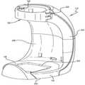
본 발명을 따르는 병 장착 시스템(bottle mounting system)은 도 1에 도시되고 도면부호 10으로 지정된다. 상기 병 장착 시스템(10)은 병 홀더(bottle holder)(12) 및 클램프(14)를 포함한다. 상기 클램프(14)는 선택적으로 (즉 개인의 요구에 따라) 다양한 지지부재에 장착되고 상기 병 홀더(12)는 선택적으로 상기 클램프(14)에 장착된다. 상기 방법에 의해, 상기 병 홀더는, 말단 사용자에게 편리한 위치에서 병(B)을 고정하기 위해 다양한 위치에 장착될 수 있다.
A bottle mounting system according to the present invention is shown in FIG. 1 and designated 10. The
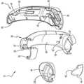
상기 병 홀더(12)는 도 2 내지 도 4를 참고하여 더욱 양호하게 이해된다. 도면에 도시된 것처럼, 상기 병 홀더(12)는 상부 표면(18)과 하부표면(20)을 제공하는 하부 벽(16)을 포함한다. 특수한 실시 예에서, 상기 상부표면(18)은, 오목부(concavity)(22)를 가지며 형성되고, 상기 오목부는 상기 오목부(22)내에 밀착되게 끼워맞춤되는 형상을 가진 단면을 가진 제 1 형태의 병(B)을 단단히 고정하기 위한 형상을 가진다. 상기 병 홀더(12)는 또한 전방 표면(26)과 후방 표면(28)을 제공하는 측벽(24)을 포함한다. 일부 실시 예들에서, 상기 측벽(24)의 상부와 근접한 위치에 게이트(gate)(30)가 제공된다. 상기 게이트(30)는 병 홀더(12)에 병(B)을 더 잘 고정하기 위해 이용된다. 상기 게이트(30)는 게이트의 한쪽 단부에서 힌지(32)에 의해 병 홀더(12)에 고정되고, 상기 힌지(32)와 마주보는 단부에 제공된 래치(latch)(34)에서 상기 병 홀더를 선택적으로 래치고정한다. 상기 래치(34)는, 상기 측벽(24)의 상부에 근접하게 제공된 캐치(catch)(35)와 구속 해제될 수 있게 연결된다. 상기 게이트(30)는 상기 병(B)의 목 주위를 둘러싸서, 상기 병은 상기 게이트(30) 및 상기 하부 벽(16)의 하부표면(20)에서 상기 병 홀더(12)내에 고정된다. 도 1에 도시된 것처럼, 상기 병(B)이 펌프 병(pump bottle)일 때, 제품을 분배하기 위해 플런저를 아래로 가압하는 하중이 상기 병을 상기 하부표면(20)을 기울이거나 떨어뜨릴지라도 상기 게이트(30)에 의해 상기 병은 제 위치에 용이하게 유지된다.
The
본 발명의 실시 예에 의하면, 상기 래치(34) 및 상기 래치와 상기 캐치(35)의 상호작용이 쉽게 눈에 띄지 않도록 상기 게이트(30)가 설계된다. 더욱 특별하게, 상기 래치(34)와 상기 캐치(35)는 쉽게 눈에 띄지 않기 때문에, 상기 병 장착 시스템 및 병 장착 시스템의 용도와 친숙하지 않은 사람들은 상기 병 홀더(12)에 병을 용이하게 고정하게 하는 게이트(30)로부터 병(B)을 구속 해제하는 방법을 알지 못하기 쉽다. 이것은, 상기 홀더로부터 상기 병(B)을 훔쳐 가려는 시도를 좌절시킬 것이고 따라서 바람직한 특징이 될 수 있다. 다른 실시 예에서, 상기 래치(34)와 캐치(35)는 상호작용하여, 상기 게이트(30)는 우선 캐치(35)를 향해 안쪽으로 가압하고 다음에 상기 래치(34)와 캐치(35)를 분리하기 위해 아래로 가압된다. 이것은 또한, 상기 병 홀더(12)로부터 다시 상기 병(B)을 쉽게 구속 해제하는 것을 좌절시키기 위해 필요할 수 있다.
According to an embodiment of the present invention, the
상기 병 홀더(12)는 적합한 모든 재료로 제조될 수 있고, 용이한 제조를 위하여 서로 조립되는 다수의 제조부품들로 제조될 수 있다. 이것은 도 4의 실시 예에 도시되며, 상기 병 홀더(12)는 상측 구성부(top half)(36) 및, 탭(tabs)(40)과 슬롯(42)들의 상호작용을 통해 서로 조립되는 하측 구성부(bottom half)(38)를 포함한다. 상기 하부 벽(16)은, 상기 하부 벽(16)을 완성하는 단부 캡(44)을 포함하고, 상기 병 홀더(12)내에서 상기 병(B)을 더 잘 고정할 수 있도록 돕는 전방 립(lip)(45)을 제공할 수 있다. 상기 단부 캡(44)은 또한, 유사한 탭들과 슬롯들을 통해 상측 구성부(36) 및/또는 하측 구성부(38)의 요소들과 상호작용하게 된다. 오목부(concavity)(22)를 제공하는 실시 예에서, 상기 단부 캡(44)은 상기 오목부(22)의 주변부를 완성하기 위해 이용될 수 있다.
The
상기 병 홀더(12)내에 서로 다른 형태의 병들을 수용하는 것이 유리할 수 있다는 것을 알 때에, 일부 실시 예에서, 서로 다른 형상을 가진 오목부(22b)를 제공하기 위해 하부 벽(16)의 상부 표면(18)과 단단히 조립되는 어댑터(46)가 제공되어, 상기 병 홀더(12)는 상기 오목부(22)내에 수용되기 위한 병(B)과 다른 제 2 형태의 병을 수용할 수 있다.
Knowing that it may be advantageous to accommodate different types of bottles in the
상기 클램프(14)의 클램프 장착 부분과 상기 병 홀더(12)를 선택적으로 결합시키기 위해, 상기 측벽(24)의 후방 표면(28)은 후방 장착부(50)를 포함하고, 상기 하측벽(16)의 하부 표면(20)은 하측 장착부(52)를 포함한다. 상기 특정 실시 예에서, 후방 장착부(50)는 마주보는 트랙(track)(51)들을 포함하고, 유사하게 하측 장착부(52)는 마주보는 트랙(53)들을 포함한다. 상기 트랙(51)의 길이 내에, 구속 해제될 수 있는 후방 래치(54)가 제공되고, 상기 트랙(53)의 입구에 구속 해제될 수 있는 래치(56)가 제공된다. 도시된 특정 실시 예에서, 상기 구속 해제될 수 있는 후방 래치(54) 및 구속 해제될 수 있는 래치(56)는 상기 병 홀더(12)의 하측 구성부(38)의 일부분을 형성하고, 상기 병 홀더(12)는 플라스틱과 같은 탄성재료로 제조되어, 상기 구속 해제될 수 있는 후방 래치(54) 및 구속 해제될 수 있는 래치(56)는 회전 가능한 힌지(living hinges)상에서 피봇회전한다. 우선, 상기 클램프(14)의 특징을 설명한 후에, 상기 구속 해제될 수 있는 래치(54, 56)들의 기능 및 상기 클램프(14)상에서 클램프 장착부와 래치들의 상호작용이 더욱 상세하게 아래에 설명된다.
To selectively engage the clamp mounting portion of the
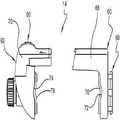
상기 클램프(14)는 도 5 내지 도 7에 더욱 특별하게 도시되고, 상기 클램프(14)는 제 1 조우(jaw)(60)를 포함하고, 상기 제 1 조우는 제 2 조우(62)와 선택적으로 결합하여, 제 1 조우의 클램프 표면(64)(도 7)은 상기 제 2 조우(62)의 클램프 표면(66)(도 7)과 떨어져 일반적으로 평행하게 연장된다. 상기 제 1 및 제 2 조우(60,62)는, 상기 클램프 표면(64,66)들사이에 지지부재를 가압하여 상기 클램프(14)를 상기 지지부재에 장착하도록 상호작용한다. 상기 특정 실시 예에서, 상기 클램프 표면(64,66)들은, 일반적으로 각각의 조우 부재(60,62)들의 각각의 몸체 부재(68,70)와 수직으로 연장되지만, 본 발명에 따라 이용하기 위한 적합한 클램프를 제공하기 충분한 다른 구조들이 발견될 수 있기 때문에, 본 발명은 도면에 도시된 특정 구조에 의해 한정되지 않는다. 특정 실시 예에서, 클램프 표면(64)은 디텐트(detent)(72)를 포함하고, 유사하게 상기 클램프 표면(66)은 상기 디텐트(72)와 사실상 정렬된 디텐트(74)를 포함할 수 있다. 상기 디텐트(72,74)들은, 디텐트(72,74)들에서 클램프 표면(64)과 클램프 표면(66)사이에서 폴(pole)을 가압하여 상기 클램프(14)가 상기 폴에 고정되는 것을 허용하도록 이용된다. 이것은, (환자에게 정맥 주사용액(intravenous solution)을 전달하기 위한) IV 스탠드(stand)의 폴에 상기 클램프를 장착하기 위해 특히 유리할 수 있다. 특정 실시 예들에서, 상기 클램프 표면(64,66)들은, 클램프(14)가 고정되는 표면에 작용하는 고정 하중(gripping force)을 완충(cushion)하고 또한 인시스(incease)하기 위해 76 및 78에 도시된 것과 같은 완충 부재로 덮여질 수 있다.
The
도 5 내지 도 7에 도시된 것처럼, 제 2 조우(62)의 몸체부재(70)는 제 1 조우(60)의 몸체부재(68)에 의해 형성된 트랙 내에서 미끄럼운동하고 이렇게 하여, 제 1 조우(60)와 제 2 조우(62)는 서로에 대해 선택적으로 결합하고 미끄럼 운동한다. 상기 제 1 및 제 2 조우(60,62)는, 상기 클램프(14)를 지지부재에 고정하기 위해 상대위치들 내에서 제 위치에 구속된다. 더욱 특별하게, 구속해제 가능한 구속부재(90)가 상기 제 2 조우(62)내에 제공되고 구속위치를 가지며 제 1 조우(60) 및 제 2 조우(62)를 서로 상대위치에 구속하여 상기 제 1 조우(60)와 제 2 조우(62)가 서로로부터 떨어져 이동하는 것을 방지한다. 구속해제 가능한 구속부재(90)는 또한, 상기 제 1 조우(60)와 제 2 조우(62)가 서로로부터 떨어져 이동하는 것을 허용하는 불 구속(non- locking) 위치를 가진다. 상기 제 1 조우(60)와 제 2 조우(62)의 상대위치들을 구속하고 구속해제하기 위한 다양한 기구들이 이용될 수 있지만, 본 발명은 도 7에 가장 잘 도시된 것처럼 멈춤쇠(pawl)와 라쳇(lachet) 기구를 이용한다.
As shown in FIGS. 5-7, the
상기 멈춤쇠(pawl)와 라쳇(lachet) 기구 내에서 멈춤쇠(92)는, 상기 제 1 조우(60)와 제 2 조우(62)가 서로에 대해 미끄럼 운동하여 클램프 표면(66)을 상기 클램프 표면(64)에 더욱 근접하게 끌어당김에 따라 라쳇(94)상에서 제 2 조우(62)와 라쳇들에 의해 제공된다. 상기 멈춤쇠(92)는 정상적으로 상기 라쳇(94)과 결합하도록 편향되지만, 상기 클램프 표면(64,66)들이 서로 근접하게 당겨짐에 따라 라쳇(94)의 다수의 치형부(teeth)(96)들이 라쳇(ratchet)구속될 정도로 충분한 탄성을 가진다. 상기 라쳇(94)의 선형 랙(rack)(98)은 기울어진 표면(97)을 가진 다수의 치형부(96)들을 제공하고, 상기 클램프 표면(64,66)들을 서로 근접하게 끌어당기기 위한 선형운동 시 상기 표면 위에 상기 멈춤쇠(92)가 라쳇구속되고, 상기 클램프 표면(64,66)들을 더욱 분리시키려는 시도가 있을 때 상기 멈춤쇠(92)가 상기 선형 랙(98)에 대해 운동하는 것을 방지하는 (도 7의 방향으로)수직의 정지 표면(99)들을 추가로 포함한다. 상기 클램프 표면(64,66)들이 서로로부터 더욱 떨어지는 것을 허용하기 위해, 상기 멈춤쇠(92)의 원위 단부와 연결되는 스위치(100)가 가압되어야 한다. 상기 스위치(100)를 가압하면, 구속부재(90)는 구속부재의 불구속 위치로 이동한다. 더욱 특별하게, 상기 스위치(100)는 제 2 조우(62)에 피봇운동하게 장착되고, 상기 스위치는 상기 스위치(100)의 몸체에 고정된 한쪽 단부 및 도면부호 103으로 도시된 제 2 조우(62)의 정지 구조체와 연결된 다른 한쪽 단부를 가진 탄성 아암(102)에 의해 구속위치로 편향된다. 상기 탄성부재(102)는 상기 스위치(100)의 몸체를 통해 힌지(104)의 한쪽 측부에서 상기 스위치(100)의 나머지와 결합되고, 멈춤쇠 래치(pawl latch)(106)는 상기 멈춤쇠(92)의 원위 단부(107)와 연결된다. 상기 스위치(100)가 가압될 때, 스위치는 탄성아암(102)의 편향작용에 대해 피봇운동하여, 멈춤쇠 래치(106)는 상승되고 따라서 상기 멈춤쇠(92)의 구속 팁(tip)(108)을 상승시켜서 라쳇트 치형부(96)로부터 분리되게 만든다. 더욱 특별하게, 상기 스위치(100)를 가압하면 상기 멈춤쇠는 상기 치형부(96)의 정지 표면(98)위로 상승하여, 상기 제 1 조우(60)와 제 2 조우(62)가 상대 운동할 수 있고 클램프 표면(64,66)들은 서로로부터 떨어져 이동한다.
In the pawl and the lachet mechanism, the
따라서, 상기 클램프(14)는 상기 클램프 표면(64,66)들 사이에서 지지부재를 가압하여 지지부재에 장착될 수 있고, 구속해제 가능한 구속부재(90)를 구속해제하고 상기 제 1 조우(60)와 제 2 조우(62)가 떨어져 이동하도록 상기 스위치(100)를 가압하여 상기 클램프(14)는 지지부재상의 장착위치로부터 분리될 수 있는 것을 알 수 있다. 상기 클램프 표면(64,66)들의 분리거리에 의해 형성되는 마우스(mouth)(110)는, 상기 멈춤쇠(92)가 상기 랙(98)의 최대 원위(most distal) 치형부(96)와 연결되는 위치에서 형성되는 최대 폭(도 7의 방향으로)을 가지게 된다는 것을 알게 된다. 상기 클램프(14)는, 상기 마우스(110)내에 조립될 수 있는 모든 지지부재에 장착될 수 있다. 테이블 또는 카운터(counter)의 모서리에 장착될 때 상기 클램프 표면(64,66)들이 가지는 일반적으로 평평한 표면들은 테이블의 마주보는 표면들과 연결되고, 폴에 장착될 때 상기 폴은 디텐트(72,74)들에 위치하게 된다.
Accordingly, the
초기에 상기 클램프(14)를 지지부재에 고정하기 위해 손으로 조이는 작업이 이용될 수 있다. 특히, 상기 클램프(14)의 마우스(110)는 상기 지지부재상에 배열될 수 있고, 개인은 상기 클램프 표면(64,66)들을 상기 지지부재와 연결시키기 위해 제 1 및 제 2 조우(60,62)를 가압할 수 있다. 일부 개인들은 클램프를 지지부재에 안정되게 고정하도록 상기 클램프(14)를 적절하게 가압하기 위한 손 힘을 가질 수 없기 때문에, 상기 클램프(14)를 지지부재에 적합하게 고정할 정도로 손의 압력이 충분하지 못할 수 있다. 따라서, 상기 제 1 및 제 2 조우(60,62)들을 서로를 향해 가압하여 초기의 매크로 조정(macro- adjustment)이 손으로 수행된 후에 상기 클램프(14)를 상기 지지부재에 추가로 조이기 위해 마이크로 조정(micro- adjustment) 부재(120)가 제공된다. 도시된 실시 예에서, 마이크로 조정부재(120)는, 클램프 표면(66)이 고정되는 나사구조의 나사(122)를 포함한다. 상기 나사구조의 나사(122)는 제 2 조우(62)내에서 나사구조의 구멍(124)을 통해 연장되어, 상기 나사구조의 나사(122)는 클램프 표면(64)에 대한 클램프 표면(66)의 위치를 조정하기 위해 선택적으로 회전 운동될 수 있다. 상기 나사구조의 나사(122)를 회전시키기 위한 노브(knob)(126)가 제공되고, 상기 나사(122)를 한쪽 방향으로 회전시키면 클램프 표면(66)은 클램프 표면(64)을 향해 이동하고, 나사구조의 나사(122)를 다른 방향으로 회전시키면 상기 클램프 표면(66)은 상기 클램프 표면(64)으로부터 떨어져 이동한다.
Initially, hand tightening may be used to secure the
클램프 장착부(80)가 제 1 조우(60)로부터 더욱 특별히 상기 클램프 표면(64)과 반대쪽으로 연장된다. 상기 클램프 장착부(80)는 후방 장착부(50) 또는 하측 장착부(52)와 상호작용하여, 병 홀더(12)는 상기 클램프(14)에 장착될 수 있다. 따라서, 상기 하측 장착부(52) 및 클램프 장착부(80)는 상기 병 홀더(12)를 상기 제 1 조우(60)에 병 장착 방향으로 장착하기 위해 선택적으로 결합되고, 상기 후방 장착부(50)와 클램프 장착부(80)는 상기 병 홀더(12)를 상기 제 1 조우(60)에 후방 장착(rear- mounted)방향으로 장착하기 위해 선택적으로 결합된다.
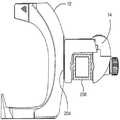
The
상기 실시 예에서, 상기 클램프 장착부(80)는 포스트(post)(82) 및 이로부터 연장되는 플랜지(84)를 포함한 숫 장착부(male mount)이다. 상기 포스트(82)는 상기 제 1 조우(60)의 장착 측부(61)로부터 떨어져 상기 플랜지(84)를 들어올려서, 상기 플랜지(84)는 상기 후방 장착부(50)와 하측 장착부(52)의 트랙(51,53)들 중 한 개속으로 수용될 수 있다. 더욱 특별하게, 상기 클램프(14)는 지지표면에 장착될 수 있고, 병 홀더(12)를 상기 트랙(51,53)들 중 한 개에서 상기 클램프 장착부(80)상에 미끄럼 운동시켜서 병 홀더(12)가 클램프에 장착될 수 있다. 본 명세서에 공개된 특정 실시 예가 클램프 장착부(80)에서 숫 장착부를 도시하고 트랙(51,53)들에서 암 장착부(female mmount)를 도시할지라도, 후방 장착부와 하측 장착부가 동일한 것으로 선택된다는 조건하에 하측 장착부는 숫 장착부와 암 장착부로부터 선택될 수 있고 후방 장착부는 숫 장착부와 암 장착부로부터 선택될 수 있으며, 후방 장착부와 하측 장착부가 숫 장착부로 선택되면 클램프 장착부는 암 장착부로 선택되고, 후방 장착부와 하측 장착부가 암 장착부로 선택되면 클램프 장착부는 숫 장착부로 선택된다는 조건하에 클램프 장착부는 숫 장착부와 암 장착부로부터 선택된다는 것을 알아야 한다.
In this embodiment, the
지금 도 8을 참고할 때, 클램프(14)는 수직으로 연장된 지지부재(200)로 장착될 수 있어서 클램프 장착부(80)는 제 1 조우(60)의 수직 표면(202)내에 제공되고, 병 홀더(12)를 후방장착 방향으로 제공하기 위해 후방 장착부(50)는 선택적으로 클램프 장착부(80)와 결합하며, 16 하부벽의 상부 표면(18)은 일반적으로 수직으로 연장되어 병은 상부표면에서 사용하기 적합한 방향을 향해 선택적으로 수용된다. 수직으로 연장되는 지지부재(200)는 단순하게 벽이지만 폴(pole)도 적합할 것으로 이해해야 한다.
Referring now to FIG. 8, the
도 9에서, 클램프 장착부(80)는 간단하게 수직 표면(204)내에 제공되지만, 상기 클램프(14)는 수직으로 연장되는 지지부재(206)에 장착되며, 상기 클램프(14)의 개방된 마우스(110)는 도 8에 도시된 것처럼 수평방향으로 마주보며 하측으로 연장된다. 후방 장착부(50)는 상기 병 홀더(12)를 후방 장착 방향으로 제공하기 위해 클램프 장착부(80)와 선택적으로 결합하고, 상기 16 하부벽의 상부 표면(18)은 일반적으로 수평으로 연장되어, 병은 사용하기 적합한 방향으로 상부표면(18)에 선택적으로 수용된다. 클램프(14)와 관련하여, 도 8에 도시된 병 홀더(12)는 도 9의 병 홀더(12)와 비교하여 90도 회전된다. 따라서, 병 장착 시스템은, 병을 원하는 위치에 장착하는 것에 영향을 주도록 어떻게 구성될 것인지와 관련하여 매우 다용도로 이용될 수 있다.
In FIG. 9, the
추가의 다양한 용도가 도 10과 도 11에 도시된다. 도 10에서, 상기 클램프(14)는 수평으로 연장된 지지부재(208)에 장착되어 클램프 장착부(80)는 제 1 조우(60)의 수평평면(210)내에 제공되고, 병 홀더(12)를 후방 장착 방향으로 제공하기 위해 하측 장착부(50)는 상기 클램프 장착부(80)와 선택적으로 결합되며, 상기 하부벽(16)의 상부 표면(18)은 일반적으로 수평으로 연장되어, 병은 사용하기 위한 적합한 방향으로 상부표면(18)에 선택적으로 수용된다. 도 11에서, 병 홀더(12)는 또한 도 10에 도시된 것처럼 장착된 클램프(14)에 장착되지만, 병 홀더(12)는 클램프(14)에 대해 "A"로 표시된 수직축 주위에서 180도 회전된다. 특히, 플랜지(84)는 정사각형의 주변부를 가지기 때문에, 상기 수직 축(A) 주위에서 90도 회전된 네 개의 서로 다른 위치들에 병 홀더(12)를 장착할 수 있을 것이다.
Further various uses are shown in FIGS. 10 and 11. In FIG. 10, the
따라서, 회전방향으로 서로 오프셋(offset)된 다양한 위치들에서 상기 병 홀더(12)를 후방 장착방향으로 상기 클램프 장착부(80)에 장착시킬 수 있도록 클램프 장착부(80)는 다수의 방향들로 후방 장착부(50)내에 선택적으로 수용된다. 또한 유사하게, 회전방향으로 서로 오프셋된 다양한 위치들에서 상기 병 홀더(12)를 하부 장착방향으로 상기 클램프 장착부(80)에 장착시킬 수 있도록 클램프 장착부(80)는 다수의 방향들로 하부 장착부(52)내에 선택적으로 수용된다. 본 명세서에 도시된 실시 예에서 결합하는 숫 및 암 장착부 부재들을 가진 특수 시스템이 이용될 때, 상기 병 홀더(12)를 상기 클램프 장착부(80)에 대해 간단히 회전시켜서 상기 병 홀더를 상당한 갯수의 방향들로 장착시킬 수 있다.
Accordingly, the
특히, 상기 클램프 장착부(80)의 플랜지(84)는, 짝수 개의 변을 가진 정다각형(regular polygon)(이 경우 정사각형)을 형성하는 외측변(outermost edges)들을 가진 주변부를 가진다. 상기 다각형(정사각형)의 마주보는 변들은, 트랙(51 또는 53)내에 수용될 수 있어서, 정다각형의 마주보는 두 변들의 제 1 세트가 제 1 방향 또는 상기 제 1 방향으로부터 180도 오프셋 된 제 2 방향으로 트랙(51 또는 53)내에 선택적으로 수용되고, 정다각형의 마주보는 두 변들의 제 2 세트가 제 3 방향 또는 상기 제 3 방향으로부터 180도 오프셋 된 제 4 방향으로 트랙(51 또는 53)내에 선택적으로 수용된다. 상기 병 홀더(12)는 90도 증분으로 오프셋 된 서로 다른 방향들로 장착될 수 있다. 이러한 사상은 비록 짝수지만 더 많은 개수의 변들을 가진 정다각형을 형성하는 주변부들을 가진 숫 장착 플랜지들에 적용될 수 있어서, 상기 다각형의 마주보는 변들이 동일한 길이로 떨어져 있고 따라서 암 장착부에 의해 제공되는 트랙들 내에 수용될 수 있다는 것을 이해해야 한다. 6개의 변을 가진 정다각형(즉, 육각형)을 형성하는 주변부를 가진 숫 장착 플랜지에 있어서, 병 홀더(12)는 60도 증분으로 오프셋 된 서로 다른 방향들로 장착될 수 있고, 숫 장착 플랜지는 8 개의 변을 가진 정다각형 (즉 팔각형)을 형성할 때, 병 홀더(12)는 45도 증분으로 오프셋 된 서로 다른 방향들로 장착될 수 있다.
In particular, the
숫 장착부가 (포스트 및 플랜지 형상으로) 클램프(14)상에 도시되고 암 장착부가 (마주보는 트랙형태로) 병 홀더(12)내에 도시되지만, 이러한 위치들은 전환(switch)될 수 있다는 것을 주목해야 한다. 즉, 병 홀더(12)는 후방 및 하부에서 숫 장착부들을 제공하고, 클램프는 병 홀더의 후방 또는 하부에서 숫 장착부에 선택적으로 수용하기 위한 암 장착부를 제공할 수 있다.
It should be noted that while the male mount is shown on the clamp 14 (in post and flange shapes) and the arm mount is shown in the bottle holder 12 (in the form of an opposing track), these positions may be switched. do. That is, the
상기 병 홀더(12)가 후방 장착부(50)에서 클램프 장착부(80)에 장착될 때, 클램프 장착부(80)는 구속해제 가능한 후방 래치(54)의 경사진 표면(130)위에 미끄럼운동하고 다음에 상기 구속해제 가능한 후방 래치(54)의 정지 표면(132)에 의해 후방 장착부(50)내에서 제 위치에 고정된다. 상기 구속해제 가능한 후방 래치(54)는 회전하는 힌지(living hinge)(134)에 의해 쉽게 이동하고 병 홀더(12)가 장착됨에 따라 클램프 장착부(80)의 경로로부터 벗어나 이동하며, 다음에 완전히 제 위치로 미끄럼 운동하면 병 홀더(12)의 분리를 방지하기 위해 상기 경로로 이동한다. 상기 후방 장착부(50)에 장착될 때, 상기 정지 표면(132)이 상기 클램프 장착부(80)의 분리경로로부터 벗어나도록 하중을 주기 위해 상기 구속해제 가능한 후방 래치(54)는 가압되고, 상기 병 홀더(12)는 상기 클램프(14)로부터 분리될 수 있다. 유사하게, 병 홀더(12)가 하측 장착부(52)에서 클램프 장착부(80)에 장착될 때, 상기 클램프 장착부(80)는 구속해제 가능한 후방 래치(56)의 경사진 표면(136)위로 미끄럼운동하고 다음에 구속해제 가능한 후방 래치(56)의 정지 표면(138)에 의해 하측 장착부(52)내에서 제 위치에 고정된다. 상기 구속해제 가능한 후방 래치(56)는 회전하는 힌지(140)에 의해 쉽게 이동하고 병 홀더(12)가 장착됨에 따라 클램프 장착부(80)의 경로로부터 벗어나 이동하며, 다음에 완전히 제 위치로 미끄럼 운동하면 병 홀더(12)의 분리를 방지하기 위해 상기 경로로 이동한다. 상기 하측 장착부(52)에 장착될 때, 상기 정지 표면(138)이 상기 클램프 장착부(80)의 분리경로로부터 벗어나도록 하중을 주기 위해 상기 구속해제 가능한 후방 래치(56)는 가압되고, 상기 병 홀더(12)는 상기 클램프(14)로부터 분리될 수 있다.
When the
본 발명의 병 장착 시스템에 의하면, 시설내부의 다양한 위치들에 다수의 클램프(14)들을 배열할 수 있고, 원하는 제품을 유지하는 관련 병들을 가지고 한 개 이상의 병 홀더(12)들이 필요에 따라 주어진 클램프(14)에 장착되도록 시설에서 직원들에 의해 운반될 수 있다. 예를 들어, 병원 내에서 클램프(14)들은 모든 병실 및 IV 스탠드 및 침실 및 수술실 및 복도(hallway)에 장착될 수 있고, 병원 직원들은 자신의 병 홀더주위에서 손 소독제의 관련 병을 운반할 수 있고, 필요에 따라 상기 손 소독제의 병을 주어진 실내, 침실, 복도 등에 장착할 수 있다. 이렇게 하여, 원하는 제품, 이 경우 소독제의 병을 주어진 직원이 쉽게 이용할 수 있고 다수의 위치들에서 영구적으로 병 또는 분배기를 장착하는 것이 불필요하다. 영구적으로 장착되는 병 및 분배기(dispenser)들과 비교하여 상대적으로 저렴한 클램프들이 다수의 지지부재들에 장착될 수 있고, 상대적으로 적은 개수의 병 홀더들 및 관련 병들이 원하는 대로 장착되고 이용되도록 주위로 운반될 수 있다.
According to the bottle mounting system of the present invention, a plurality of
상기 설명을 고려할 때, 본 발명은 다수의 방법에 따라 구조적이고 기능적으로 개선된 병 장착 시스템을 제공하여 기술을 상당히 발전시킨다고 이해되어야 한다. 상기 병 장착 시스템은, 선택된 영역들에서 손 위생제품의 병들을 제공하고 이용을 촉진하는 데 특히 유용한 것임을 알게 될 수 있고, 환자의 관리 및 식품 산업은 병 장착 시스템의 이용으로부터 구체적으로 혜택을 얻을 수 있다. 사실, 상기 병 장착 시스템의 폴(pole)- 장착 능력은, 환자용 IV 스탠드에 제품의 병을 장착하는 데 특히 유용할 수 있다. 그러나, 본 발명은 특정 제품 또는 특정 환경으로 국한되지 않는다.In view of the above description, it should be understood that the present invention significantly advances the technology by providing a structurally and functionally improved bottle mounting system according to a number of methods. It will be appreciated that the bottle mounting system is particularly useful for providing and facilitating the use of bottles of hand hygiene products in selected areas, where the patient care and food industry can specifically benefit from the use of the bottle mounting system. have. In fact, the pole-mounting capability of the bottle mounting system can be particularly useful for mounting a bottle of product on a patient IV stand. However, the present invention is not limited to any particular product or environment.
Claims (20)
Translated fromKorean상부표면 및 하부 표면을 가진 하부벽,
전방 표면 및 후방 표면을 가진 측벽, 및
상기 하부벽의 상기 하부표면에 제공된 하측 장착부 및
상기 측벽의 상기 후방 표면에 제공된 후방 장착부를 포함하고,
(b) 클램프를 포함하며, 상기 클램프는
제 1 클램프 표면 및 클램프 장착부를 제공하는 제 1 조우를 포함하고, 상기 하측 장착부와 상기 클램프 장착부는 상기 병 홀더를 상기 제 1 조우에 하부 장착방향으로 장착하기 위해 선택적으로 결합되며, 상기 후방 장착부와 상기 클램프 장착부는 상기 병 홀더를 제 1 조우에 후방 장착방향으로 장착하기 위해 선택적으로 결합하고,
제 2 클램프 표면을 제공하는 제 2 조우를 포함하며, 상기 제 2 조우는 상기 제 1 조우와 결합하고, 상기 제 1 조우는 상기 제 2 조우에 대해 미끄럼운동하며, 상기 제 1 조우 및 제 2 조우는 상기 제 1 및 제 2 클램프 표면들 사이에 상기 지지부재를 가압하여 상기 클램프를 지지부재에 장착하도록 상호작용하고, 상기 제 1 클램프 표면은 상기 제 1 조우와 결합하며, 상기 제 2 클램프 표면들은 상기 제 2 조우와 이동하고,
구속 해제될 수 있는 구속부재를 포함하며, 상기 구속부재는 상기 제 1 조우와 제 2 조우가 서로로부터 떨어져 이동하는 것을 방지하기 위해 구속부재가 상기 제 1 조우와 제 2 조우를 서로에 대해 상대위치에 구속하는 구속위치 및, 제 1 조우와 제 2 조우가 서로로부터 떨어져 이동하는 것을 허용하는 불구속위치를 가지는 것을 특징으로 하는 병 장착 시스템.
(a) a bottle holder, the bottle holder
A bottom wall having an upper surface and a lower surface,
Sidewalls with anterior and posterior surfaces, and
A lower mounting portion provided on the lower surface of the lower wall and
A rear mount provided on the rear surface of the side wall,
(b) a clamp, wherein the clamp
A first jaw providing a first clamp surface and a clamp mount, wherein the lower mount and the clamp mount are selectively coupled to mount the bottle holder to the first jaw in a lower mounting direction; The clamp mounting portion is selectively coupled to mount the bottle holder to the first jaw in a rear mounting direction,
A second jaw that provides a second clamp surface, the second jaw engaging the first jaw, the first jaw sliding relative to the second jaw, the first jaw and the second jaw Pressurizes the support member between the first and second clamp surfaces to mount the clamp to the support member, the first clamp surface engages the first jaw, and the second clamp surfaces Move with the second encounter,
A restraining member that can be restrained, the restraining member having a restraining member relative to each other relative to each other to prevent the first jaw and the second jaw from moving away from each other; And a restraint position to allow the first and second jaws to move away from each other.
상기 제 1 조우와 제 2 조우 중 한 개에 의해 고정되는 멈춤쇠 및,
상기 제 1 조우와 제 2 조우 중 다른 한 개에 의해 고정되는 라쳇 래크(ratchet rack)를 포함하고, 상기 라쳇 래크는 치형부를 제공하며, 상기 멈춤쇠는 연결위치에서 상기 라쳇 래크의 상기 치형부와 연결되도록 편향되고, 상기 연결위치에서 상기 제 1 클램프 표면이 상기 제 2 클램프 표면을 향할 때 상기 멈춤쇠는 상기 치형부상에 라쳇(ratchet)구속되며, 상기 연결위치에서 상기 멈춤쇠는 상기 제 1 클램프 표면이 상기 제 2 클램프표면으로부터 떨어져 운동하는 것을 방지하는 것을 특징으로 하는 병 장착 시스템.The method of claim 1, wherein the restraint restraint member,
A detent fixed by one of the first and second jaws,
A ratchet rack secured by the other of said first and second jaws, said ratchet rack providing a tooth, said pawl connecting said tooth of said ratchet rack in a connected position; Biased, the detent latches onto the tooth when the first clamp surface faces the second clamp surface at the joining position, the detent at the joining position wherein the first clamp surface is Preventing movement away from the second clamp surface.
상기 멈춤쇠와 연결되는 스위치를 포함하고, 상기 멈춤쇠를 상기 연결위치로부터 상기 멈춤쇠가 상기 라쳇 래크의 상기 치형부와 연결되지 않고 상기 제 1 클램프 표면이 상기 제 2 클램프 표면으로부터 떨어져 이동하는 것을 방해 받지 않는 분리위치로 이동시키기 위해 상기 스위치가 선택적으로 조정되는 것을 특징으로 하는 병 장착 시스템.16. The method of claim 15, wherein the restrainable restraint member further comprises:
And a switch in communication with the detent, wherein the detent is moved from the connecting position such that the detent is not connected to the teeth of the ratchet rack and the first clamp surface moves away from the second clamp surface. And the switch is selectively adjusted to move to an unobstructed disengagement position.
복수 개의 클램프들을 제공하는 단계를 포함하고, 각각의 클램프는 시설내부의 원하는 위치에서 지지부재에 장착되며,
복수 개의 병 홀더들을 제공하는 단계를 포함하고, 각각의 병 홀더는 시설내부에서 이용하기 위해 원하는 제품을 고정하는 병을 유지하며, 각각의 병 홀더는 상기 복수 개의 클램프들 중 어느 하나에 선택적으로 장착될 수 있고,
상기 복수 개의 병 홀더들 중 한 개를 시설내부의 개인들에게 제공하는 단계를 포함하며, 상기 개인들은, 상기 복수 개의 클램프들 중 한 개가 위치하는 주어진 분명한 위치로 상기 병 홀더를 이동시키고 사용하기 위해 원하는 위치에 병 내부에 유지된 제품의 병을 제공하기 위해 상기 병 홀더를 상기 클램프에 선택적으로 장착하는 것을 특징으로 하는 방법.
A method for providing a desired product for use at a desired location within a facility,
Providing a plurality of clamps, each clamp being mounted to a support member at a desired location within the facility,
Providing a plurality of bottle holders, each bottle holder holding a bottle to hold a desired product for use within the facility, each bottle holder selectively mounted to any one of the plurality of clamps Can be,
Providing one of the plurality of bottle holders to individuals within the facility, the individuals for moving and using the bottle holder to a given clear position where one of the plurality of clamps is located; Selectively mounting the bottle holder to the clamp to provide a bottle of product held inside the bottle at a desired location.
Applications Claiming Priority (3)
| Application Number | Priority Date | Filing Date | Title |
|---|---|---|---|
| US13/007,018 | 2011-01-14 | ||
| US13/007,018US20120181405A1 (en) | 2011-01-14 | 2011-01-14 | Bottle mounting system including separable bottle and clamp |
| PCT/US2012/021235WO2012097246A1 (en) | 2011-01-14 | 2012-01-13 | Bottle mounting system including separable bottle and clamp |
Publications (1)
| Publication Number | Publication Date |
|---|---|
| KR20140020860Atrue KR20140020860A (en) | 2014-02-19 |
Family
ID=45554846
Family Applications (1)
| Application Number | Title | Priority Date | Filing Date |
|---|---|---|---|
| KR1020137020327AWithdrawnKR20140020860A (en) | 2011-01-14 | 2012-01-13 | Bottle mounting system including separatable bottle and clamp |
Country Status (14)
| Country | Link |
|---|---|
| US (1) | US20120181405A1 (en) |
| EP (1) | EP2663800B1 (en) |
| JP (1) | JP2014507341A (en) |
| KR (1) | KR20140020860A (en) |
| CN (1) | CN103403434A (en) |
| AU (1) | AU2012205392A1 (en) |
| BR (1) | BR112013017954A2 (en) |
| CA (1) | CA2824742A1 (en) |
| DK (1) | DK2663800T3 (en) |
| ES (1) | ES2455690T3 (en) |
| MX (1) | MX2013008148A (en) |
| PT (1) | PT2663800E (en) |
| TW (1) | TW201236929A (en) |
| WO (1) | WO2012097246A1 (en) |
Cited By (2)
| Publication number | Priority date | Publication date | Assignee | Title |
|---|---|---|---|---|
| KR101939979B1 (en) | 2018-07-11 | 2019-01-18 | 진선미 | Perfume pumping apparatus |
| KR20220059803A (en)* | 2020-11-03 | 2022-05-10 | 임해원 | Tableware system customized for pets |
Families Citing this family (54)
| Publication number | Priority date | Publication date | Assignee | Title |
|---|---|---|---|---|
| US9526920B2 (en) | 2010-10-12 | 2016-12-27 | Smith & Nephew, Inc. | Medical device |
| EP2852333B1 (en) | 2012-05-22 | 2021-12-15 | Smith & Nephew plc | Apparatuses for wound therapy |
| USD777020S1 (en)* | 2013-01-25 | 2017-01-24 | Gojo Industries, Inc. | Bottle holder, adapter and clamp assembly |
| US9737649B2 (en) | 2013-03-14 | 2017-08-22 | Smith & Nephew, Inc. | Systems and methods for applying reduced pressure therapy |
| USD764654S1 (en) | 2014-03-13 | 2016-08-23 | Smith & Nephew, Inc. | Canister for collecting wound exudate |
| JP2016517318A (en)* | 2013-03-14 | 2016-06-16 | スミス アンド ネフュー インコーポレーテッド | System and method for administering decompression therapy |
| WO2015023515A1 (en) | 2013-08-13 | 2015-02-19 | Smith & Nephew, Inc. | Systems and methods for applying reduced pressure therapy |
| EP3048941A1 (en)* | 2013-09-26 | 2016-08-03 | Gojo Industries, Inc. | Modular point of care dispenser system |
| CN104590075B (en)* | 2013-10-31 | 2017-08-04 | 福特环球技术公司 | Glass stand and the car door comprising glass stand |
| US20150224659A1 (en)* | 2014-02-10 | 2015-08-13 | Edlund Company, Llc | Food Product Cutting Apparatus Having Onboard Pusher and Blade Cartridge Storage, and Pusher/Blade Cartridge Sets Suitable Therefor |
| USD764048S1 (en) | 2014-05-28 | 2016-08-16 | Smith & Nephew, Inc. | Device for applying negative pressure to a wound |
| USD764047S1 (en) | 2014-05-28 | 2016-08-16 | Smith & Nephew, Inc. | Therapy unit assembly |
| USD764653S1 (en) | 2014-05-28 | 2016-08-23 | Smith & Nephew, Inc. | Canister for collecting wound exudate |
| CN105276344B (en)* | 2014-05-30 | 2019-02-01 | 盛美半导体设备(上海)有限公司 | Photoetching glue bottle holding unit |
| USD770173S1 (en) | 2014-06-02 | 2016-11-01 | Smith & Nephew, Inc. | Bag |
| USD765830S1 (en) | 2014-06-02 | 2016-09-06 | Smith & Nephew, Inc. | Therapy unit assembly |
| CA3179001A1 (en) | 2014-07-31 | 2016-02-04 | Smith & Nephew, Inc. | Systems and methods for applying reduced pressure therapy |
| US12133789B2 (en) | 2014-07-31 | 2024-11-05 | Smith & Nephew, Inc. | Reduced pressure therapy apparatus construction and control |
| US10258705B2 (en)* | 2014-10-03 | 2019-04-16 | Patrick Daniel Bord | Sanitizing device for tool and cart handles |
| CA2972701A1 (en) | 2014-12-30 | 2016-07-07 | Smith & Nephew, Inc. | Systems and methods for applying reduced pressure therapy |
| CA2981181C (en)* | 2015-04-01 | 2023-10-03 | Ecolab Usa Inc. | Flexible mounting system for hand hygiene dispensers |
| US11315681B2 (en) | 2015-10-07 | 2022-04-26 | Smith & Nephew, Inc. | Reduced pressure therapy device operation and authorization monitoring |
| DE102015120279A1 (en) | 2015-11-24 | 2017-05-24 | Bode Chemie Gmbh | Container fixing system |
| EP4393526A3 (en) | 2016-02-12 | 2024-08-14 | Smith & Nephew, Inc | Systems and methods for detecting operational conditions of reduced pressure therapy |
| CN109069713A (en) | 2016-05-13 | 2018-12-21 | 史密夫和内修有限公司 | Automatic wound in negative pressure wound treating system couples detection |
| US12263294B2 (en) | 2016-09-28 | 2025-04-01 | T.J.Smith And Nephew, Limited | Systems and methods for operating negative pressure wound therapy devices |
| WO2018064077A2 (en) | 2016-09-29 | 2018-04-05 | Smith & Nephew, Inc. | Construction and protection of components in negative pressure wound therapy systems |
| USD835648S1 (en) | 2016-10-27 | 2018-12-11 | Smith & Nephew, Inc. | Display screen or portion thereof with a graphical user interface for a therapy device |
| US10342391B2 (en)* | 2016-12-01 | 2019-07-09 | Colgate-Palmolive Company | Bottle holder |
| WO2018165049A1 (en) | 2017-03-07 | 2018-09-13 | Smith & Nephew, Inc. | Reduced pressure therapy systems and methods including an antenna |
| WO2018195101A1 (en) | 2017-04-19 | 2018-10-25 | Smith & Nephew, Inc. | Negative pressure wound therapy canisters |
| WO2019014141A1 (en) | 2017-07-10 | 2019-01-17 | Smith & Nephew, Inc. | Systems and methods for directly interacting with communications module of wound therapy apparatus |
| US11246442B2 (en)* | 2017-09-15 | 2022-02-15 | Scott Larsen Huff | Bottle holder assembly attachable to a table top edge |
| JP7003536B2 (en)* | 2017-09-27 | 2022-01-20 | Toto株式会社 | Water soap supply device |
| IT201800010692A1 (en)* | 2018-11-29 | 2020-05-29 | Gfl S A | DISPENSING GROUP |
| GB201820668D0 (en) | 2018-12-19 | 2019-01-30 | Smith & Nephew Inc | Systems and methods for delivering prescribed wound therapy |
| SE543349C2 (en)* | 2019-03-07 | 2020-12-08 | Ikea Supply Ag | Lamp mount assembly, and lamp assembly comprising lamp mount assembly |
| USD866282S1 (en)* | 2019-04-08 | 2019-11-12 | Tatsuno Corporation | Nozzle hook |
| GB201911693D0 (en) | 2019-08-15 | 2019-10-02 | Smith & Nephew | Systems and methods for monitoring essential performance of wound therapy |
| USD1002387S1 (en) | 2019-10-03 | 2023-10-24 | Marietta Corporation | Bottle and a mount assembly |
| GB201914283D0 (en) | 2019-10-03 | 2019-11-20 | Smith & Nephew | Apparatuses and methods for negative pressure wound therapy |
| SE543666C2 (en)* | 2019-10-16 | 2021-05-25 | Runius Design | Lockable receptacle holder |
| DE102020113515B3 (en)* | 2020-05-19 | 2021-06-24 | Krömker Holding GmbH | Container receiving device and holder for this |
| DE102020114873A1 (en) | 2020-06-04 | 2021-12-09 | JUNO-Metalltechnik GmbH | Holder for a dispenser for liquid or paste-like substances for disinfection and uses thereof |
| US11332279B2 (en)* | 2020-09-25 | 2022-05-17 | World Club Supply Corporation | Liquid dispenser apparatus |
| WO2022159378A1 (en) | 2021-01-20 | 2022-07-28 | Ecolab Usa Inc. | Product dispenser holder with compliance module |
| USD995309S1 (en)* | 2021-03-23 | 2023-08-15 | Marietta Corporation | Bottle mount assembly with insert tool |
| WO2022237985A1 (en)* | 2021-05-13 | 2022-11-17 | La Bottega Dell'albergo S.P.A. | Detergent or disinfectant dispenser unit |
| USD988878S1 (en) | 2021-07-06 | 2023-06-13 | Marietta Corporation | Bottle and mount assembly |
| US11744413B2 (en) | 2021-10-07 | 2023-09-05 | Deb Ip Limited | Dispenser assembly |
| CN114224215A (en)* | 2021-12-28 | 2022-03-25 | 浙江启新科技有限公司 | Hand washing machine |
| SE2251587A1 (en)* | 2022-12-28 | 2024-06-29 | Runius Design Ab | A base fixing adapter for a lockable receptacle holder, a lockable receptacle holder, a method of securing a receptacle to a lockable receptacle holder, and use of a base fixing adapter |
| CN220174890U (en)* | 2023-05-30 | 2023-12-15 | 億泰德集團有限公司 | Wine bottle bracket |
| US12274385B2 (en)* | 2023-06-06 | 2025-04-15 | Team Ytd Co., Limited | Wine bottle holder |
Family Cites Families (34)
| Publication number | Priority date | Publication date | Assignee | Title |
|---|---|---|---|---|
| US229395A (en)* | 1880-06-29 | gordon | ||
| US2309121A (en) | 1940-10-05 | 1943-01-26 | Clifford D Keely | Receptacle and mounting therefor |
| US4014505A (en)* | 1976-06-16 | 1977-03-29 | Dowd & Holbrook Enterprises, Inc. | Nursing bottle support |
| US4627604A (en)* | 1985-04-11 | 1986-12-09 | Choi Sang B | Adjustable clamp |
| JPS61190283U (en)* | 1985-05-22 | 1986-11-27 | ||
| US4697780A (en)* | 1986-10-20 | 1987-10-06 | Uniek Plastics, Inc. | Beverage container holder |
| US4784360A (en)* | 1986-11-14 | 1988-11-15 | Peter Mok | Beverage cooler-carrier for vehicles |
| JPS63149830U (en)* | 1987-03-25 | 1988-10-03 | ||
| DE8708734U1 (en) | 1987-06-24 | 1988-10-20 | Riesselmann & Sohn KG, 2842 Lohne | Holder element for a dispenser |
| DE8810879U1 (en) | 1988-08-29 | 1989-12-28 | Wella Ag, 6100 Darmstadt | Carrying device |
| JPH03119604U (en) | 1990-03-23 | 1991-12-10 | ||
| JPH0719344Y2 (en)* | 1990-11-06 | 1995-05-10 | 幸延 安藤 | Hanging equipment for indoor lightweight equipment |
| US5322253A (en) | 1992-12-02 | 1994-06-21 | Merit Medical Systems, Inc. | Universal I.V. stand mounting system |
| JP3162857B2 (en)* | 1993-02-26 | 2001-05-08 | 三洋電機株式会社 | Remote control with built-in monitor television |
| JPH06293347A (en)* | 1993-04-06 | 1994-10-21 | Komatsu Ltd | Flexible liquid storage bag mounting holder |
| JP3668765B2 (en)* | 1994-10-17 | 2005-07-06 | 株式会社キャットアイ | Mounting device for motorcycle parts |
| JPH08322758A (en)* | 1995-05-29 | 1996-12-10 | Aron Kasei Co Ltd | Shelves with suction cups for bathroom tube containers |
| CN1242815A (en)* | 1996-11-08 | 2000-01-26 | 多利安·吉布斯 | Fixed Container Holder |
| US5842671A (en) | 1996-11-08 | 1998-12-01 | Gibbs; Dorian | Secured receptacle holder |
| JPH10337244A (en)* | 1997-04-10 | 1998-12-22 | Nitomuzu:Kk | Hanger |
| US5996957A (en) | 1998-04-02 | 1999-12-07 | Kurtz; Thomas M. | Rotational beverage holder |
| CA2266797A1 (en)* | 1999-03-25 | 2000-09-25 | Alain J. Lepine | Beverage caddy |
| US6877642B1 (en) | 2000-01-04 | 2005-04-12 | Joseph S. Kanfer | Wall-mounted dispenser for liquids |
| US6318600B1 (en)* | 2000-02-02 | 2001-11-20 | Harold G. Winnett | Dispenser for dispensing shaving cream or other aerosol dispensed products from cans having different heights and diameters |
| US7077302B2 (en)* | 2001-12-10 | 2006-07-18 | Louis Chuang | Apparatus for selectively attaching a first object to a second object in a desired orientation |
| US6820770B2 (en)* | 2002-12-06 | 2004-11-23 | The Dial Corporation | Dispenser holder for vehicles |
| US7156353B2 (en)* | 2003-07-25 | 2007-01-02 | News America Marketing Properties Llc | Product display device |
| FR2881507B1 (en) | 2005-02-01 | 2010-09-10 | Fresenius Vial | DEVICE FOR FIXING AN OBJECT IN A PRIVILEGED SPACE POSITION |
| JP4999579B2 (en)* | 2007-07-05 | 2012-08-15 | 正 小倉 | Cylindrical container with movable bottom |
| US20090032657A1 (en)* | 2007-08-03 | 2009-02-05 | Taiwan An I Co., Ltd. | Drink cup holder mount |
| US7793904B2 (en)* | 2007-08-21 | 2010-09-14 | Scarton Michael G | Beverage holder assembly |
| EP2276983A4 (en)* | 2008-03-14 | 2014-01-29 | Revolutionary Cooling Systems Inc | BOTTLE SUPPORT COMPRISING ACTIVE COOLING |
| CN201227121Y (en)* | 2008-07-31 | 2009-04-29 | 卡特彼勒公司 | Cup holder |
| US9681924B2 (en)* | 2009-03-31 | 2017-06-20 | Sean Rolfes | Skull clamp with improved positionability and cleaning capability |
- 2011
- 2011-01-14USUS13/007,018patent/US20120181405A1/ennot_activeAbandoned
- 2012
- 2012-01-13WOPCT/US2012/021235patent/WO2012097246A1/enactiveApplication Filing
- 2012-01-13PTPT127015980Tpatent/PT2663800E/enunknown
- 2012-01-13KRKR1020137020327Apatent/KR20140020860A/ennot_activeWithdrawn
- 2012-01-13JPJP2013549566Apatent/JP2014507341A/enactivePending
- 2012-01-13ESES12701598.0Tpatent/ES2455690T3/enactiveActive
- 2012-01-13DKDK12701598.0Tpatent/DK2663800T3/enactive
- 2012-01-13CACA2824742Apatent/CA2824742A1/ennot_activeAbandoned
- 2012-01-13CNCN2012800109836Apatent/CN103403434A/enactivePending
- 2012-01-13BRBR112013017954Apatent/BR112013017954A2/ennot_activeIP Right Cessation
- 2012-01-13EPEP12701598.0Apatent/EP2663800B1/ennot_activeNot-in-force
- 2012-01-13TWTW101101394Apatent/TW201236929A/enunknown
- 2012-01-13AUAU2012205392Apatent/AU2012205392A1/ennot_activeAbandoned
- 2012-01-13MXMX2013008148Apatent/MX2013008148A/enactiveIP Right Grant
Cited By (2)
| Publication number | Priority date | Publication date | Assignee | Title |
|---|---|---|---|---|
| KR101939979B1 (en) | 2018-07-11 | 2019-01-18 | 진선미 | Perfume pumping apparatus |
| KR20220059803A (en)* | 2020-11-03 | 2022-05-10 | 임해원 | Tableware system customized for pets |
Also Published As
| Publication number | Publication date |
|---|---|
| MX2013008148A (en) | 2013-12-06 |
| ES2455690T3 (en) | 2014-04-16 |
| EP2663800B1 (en) | 2014-03-26 |
| TW201236929A (en) | 2012-09-16 |
| DK2663800T3 (en) | 2014-04-22 |
| US20120181405A1 (en) | 2012-07-19 |
| JP2014507341A (en) | 2014-03-27 |
| CA2824742A1 (en) | 2012-07-19 |
| BR112013017954A2 (en) | 2019-09-24 |
| PT2663800E (en) | 2014-06-02 |
| CN103403434A (en) | 2013-11-20 |
| HK1187393A1 (en) | 2014-04-04 |
| WO2012097246A1 (en) | 2012-07-19 |
| AU2012205392A1 (en) | 2013-08-01 |
| EP2663800A1 (en) | 2013-11-20 |
Similar Documents
| Publication | Publication Date | Title |
|---|---|---|
| KR20140020860A (en) | Bottle mounting system including separatable bottle and clamp | |
| US12075954B2 (en) | Flexible mounting system for hand hygiene dispensers | |
| US20210177184A1 (en) | Retrofit curtain assembly | |
| US9339151B2 (en) | Shelving system with obscurable shelving | |
| US20090199339A1 (en) | Medical examination table and system for mounting accessories to the table | |
| JP2016504112A (en) | System, method and apparatus for clamping | |
| WO2007148125A9 (en) | A dispenser for wipes | |
| US9700666B2 (en) | Medical paraphernalia carrier assembly | |
| US20190374418A1 (en) | Two-Plane, Folding Patient Assist Handle | |
| US8820582B2 (en) | Product dispenser connector | |
| US20070018058A1 (en) | Equipment support having rotatable bumpers and hooks | |
| AU2012263075B2 (en) | Device for coupling a tool to a support bar | |
| US9878088B2 (en) | Apparatus for support of patients and medical fluid lines | |
| HK1187393B (en) | Bottle mounting system including separable bottle and clamp | |
| DE202018003655U1 (en) | Easy-to-handle device as disinfectant solution dispenser for easier disinfection and safe attachment to bedsteads | |
| CN215502279U (en) | Dispensing spoon for taking solid medicine |
Legal Events
| Date | Code | Title | Description |
|---|---|---|---|
| PA0105 | International application | Patent event date:20130731 Patent event code:PA01051R01D Comment text:International Patent Application | |
| PG1501 | Laying open of application | ||
| PC1203 | Withdrawal of no request for examination | ||
| WITN | Application deemed withdrawn, e.g. because no request for examination was filed or no examination fee was paid |