KR20140019798A - Drive head for a syringe pump - Google Patents
Drive head for a syringe pumpDownload PDFInfo
- Publication number
- KR20140019798A KR20140019798AKR1020137027228AKR20137027228AKR20140019798AKR 20140019798 AKR20140019798 AKR 20140019798AKR 1020137027228 AKR1020137027228 AKR 1020137027228AKR 20137027228 AKR20137027228 AKR 20137027228AKR 20140019798 AKR20140019798 AKR 20140019798A
- Authority
- KR
- South Korea
- Prior art keywords
- pressure sensor
- drive head
- syringe
- sensor support
- plunger
- Prior art date
- Legal status (The legal status is an assumption and is not a legal conclusion. Google has not performed a legal analysis and makes no representation as to the accuracy of the status listed.)
- Withdrawn
Links
- 230000003993interactionEffects0.000claimsdescription17
- 230000002093peripheral effectEffects0.000description11
- 239000012528membraneSubstances0.000description10
- 230000005540biological transmissionEffects0.000description9
- 230000003071parasitic effectEffects0.000description6
- 230000001419dependent effectEffects0.000description2
- 239000007788liquidSubstances0.000description2
- 239000002184metalSubstances0.000description2
- 230000000717retained effectEffects0.000description2
- 239000000853adhesiveSubstances0.000description1
- 230000001070adhesive effectEffects0.000description1
- 238000005452bendingMethods0.000description1
- 230000008878couplingEffects0.000description1
- 238000010168coupling processMethods0.000description1
- 238000005859coupling reactionMethods0.000description1
- 230000000694effectsEffects0.000description1
- 239000013013elastic materialSubstances0.000description1
- 230000014759maintenance of locationEffects0.000description1
- 239000000463materialSubstances0.000description1
- 238000005259measurementMethods0.000description1
Images


Classifications
- A—HUMAN NECESSITIES
- A61—MEDICAL OR VETERINARY SCIENCE; HYGIENE
- A61M—DEVICES FOR INTRODUCING MEDIA INTO, OR ONTO, THE BODY; DEVICES FOR TRANSDUCING BODY MEDIA OR FOR TAKING MEDIA FROM THE BODY; DEVICES FOR PRODUCING OR ENDING SLEEP OR STUPOR
- A61M5/00—Devices for bringing media into the body in a subcutaneous, intra-vascular or intramuscular way; Accessories therefor, e.g. filling or cleaning devices, arm-rests
- A61M5/14—Infusion devices, e.g. infusing by gravity; Blood infusion; Accessories therefor
- A61M5/168—Means for controlling media flow to the body or for metering media to the body, e.g. drip meters, counters ; Monitoring media flow to the body
- A—HUMAN NECESSITIES
- A61—MEDICAL OR VETERINARY SCIENCE; HYGIENE
- A61M—DEVICES FOR INTRODUCING MEDIA INTO, OR ONTO, THE BODY; DEVICES FOR TRANSDUCING BODY MEDIA OR FOR TAKING MEDIA FROM THE BODY; DEVICES FOR PRODUCING OR ENDING SLEEP OR STUPOR
- A61M5/00—Devices for bringing media into the body in a subcutaneous, intra-vascular or intramuscular way; Accessories therefor, e.g. filling or cleaning devices, arm-rests
- A61M5/14—Infusion devices, e.g. infusing by gravity; Blood infusion; Accessories therefor
- A61M5/142—Pressure infusion, e.g. using pumps
- A61M5/145—Pressure infusion, e.g. using pumps using pressurised reservoirs, e.g. pressurised by means of pistons
- A61M5/1452—Pressure infusion, e.g. using pumps using pressurised reservoirs, e.g. pressurised by means of pistons pressurised by means of pistons
- A61M5/1458—Means for capture of the plunger flange
- A—HUMAN NECESSITIES
- A61—MEDICAL OR VETERINARY SCIENCE; HYGIENE
- A61M—DEVICES FOR INTRODUCING MEDIA INTO, OR ONTO, THE BODY; DEVICES FOR TRANSDUCING BODY MEDIA OR FOR TAKING MEDIA FROM THE BODY; DEVICES FOR PRODUCING OR ENDING SLEEP OR STUPOR
- A61M5/00—Devices for bringing media into the body in a subcutaneous, intra-vascular or intramuscular way; Accessories therefor, e.g. filling or cleaning devices, arm-rests
- A61M5/14—Infusion devices, e.g. infusing by gravity; Blood infusion; Accessories therefor
- A61M5/142—Pressure infusion, e.g. using pumps
- A61M5/145—Pressure infusion, e.g. using pumps using pressurised reservoirs, e.g. pressurised by means of pistons
- A61M5/1452—Pressure infusion, e.g. using pumps using pressurised reservoirs, e.g. pressurised by means of pistons pressurised by means of pistons
- A61M5/14566—Pressure infusion, e.g. using pumps using pressurised reservoirs, e.g. pressurised by means of pistons pressurised by means of pistons with a replaceable reservoir for receiving a piston rod of the pump
- A—HUMAN NECESSITIES
- A61—MEDICAL OR VETERINARY SCIENCE; HYGIENE
- A61M—DEVICES FOR INTRODUCING MEDIA INTO, OR ONTO, THE BODY; DEVICES FOR TRANSDUCING BODY MEDIA OR FOR TAKING MEDIA FROM THE BODY; DEVICES FOR PRODUCING OR ENDING SLEEP OR STUPOR
- A61M5/00—Devices for bringing media into the body in a subcutaneous, intra-vascular or intramuscular way; Accessories therefor, e.g. filling or cleaning devices, arm-rests
- A61M5/14—Infusion devices, e.g. infusing by gravity; Blood infusion; Accessories therefor
- A61M5/168—Means for controlling media flow to the body or for metering media to the body, e.g. drip meters, counters ; Monitoring media flow to the body
- A61M5/16831—Monitoring, detecting, signalling or eliminating infusion flow anomalies
- A61M5/16854—Monitoring, detecting, signalling or eliminating infusion flow anomalies by monitoring line pressure
- A—HUMAN NECESSITIES
- A61—MEDICAL OR VETERINARY SCIENCE; HYGIENE
- A61M—DEVICES FOR INTRODUCING MEDIA INTO, OR ONTO, THE BODY; DEVICES FOR TRANSDUCING BODY MEDIA OR FOR TAKING MEDIA FROM THE BODY; DEVICES FOR PRODUCING OR ENDING SLEEP OR STUPOR
- A61M2205/00—General characteristics of the apparatus
- A61M2205/33—Controlling, regulating or measuring
- A61M2205/332—Force measuring means
Landscapes
- Health & Medical Sciences (AREA)
- Vascular Medicine (AREA)
- Engineering & Computer Science (AREA)
- Anesthesiology (AREA)
- Biomedical Technology (AREA)
- Heart & Thoracic Surgery (AREA)
- Hematology (AREA)
- Life Sciences & Earth Sciences (AREA)
- Animal Behavior & Ethology (AREA)
- General Health & Medical Sciences (AREA)
- Public Health (AREA)
- Veterinary Medicine (AREA)
- Infusion, Injection, And Reservoir Apparatuses (AREA)
Abstract
Translated fromKorean
Description
Translated fromKorean본 발명은 청구항 1 의 전제부에 따른 시린지 펌프용 구동 헤드에 관한 것이다.The present invention relates to a drive head for a syringe pump according to the preamble of
시린지를 비우기 위한 시린지 펌프는 종래 기술로부터 공지되어 있다. 예를 들어, 시린지 펌프는 시린지 내에 포함된 액체를 인체에 주입하기 위하여 의료 분야에서 사용된다. 공지된 시린지 펌프는 시린지의 플런저가 구동 헤드에 의해 시린지 배럴 내에서 이동될 수 있도록 구동 헤드의 선형 이동을 생성하기 위해 구성된 구동 메커니즘에 연결된 구동 헤드를 통상적으로 포함한다. 또한, 시린지 펌프의 작동 중에 시린지의 내부 압력을 측정할 수 있도록 구동 헤드에 압력 센서를 배치하는 것이 공지되어 있다. 이러한 구동 헤드를 포함하는 시린지 펌프는 예를 들어 EP 0 916 353 A1 에 시작되어 있다.Syringe pumps for emptying syringes are known from the prior art. For example, syringe pumps are used in the medical field to inject the liquid contained in the syringe into the human body. Known syringe pumps typically include a drive head coupled to a drive mechanism configured to produce a linear movement of the drive head such that the plunger of the syringe can be moved within the syringe barrel by the drive head. It is also known to place a pressure sensor in the drive head so that the internal pressure of the syringe can be measured during operation of the syringe pump. Syringe pumps comprising such a drive head are for example disclosed in EP 0 916 353 A1.
본 발명의 목적은 시린지 내의 내부 압력을 가능한 한 정확하게 측정할 수 있는 시린지 펌프용 구동 헤드를 제공하는 것이다.It is an object of the present invention to provide a drive head for a syringe pump that can measure the internal pressure in the syringe as accurately as possible.
이러한 과제는 청구항 1 에 따른 구동 헤드에 의해 해결된다. 본 발명의 실시형태는 종속 청구항에서 규정된다.This problem is solved by the drive head according to
본 발명에 따라, 시린지 펌프용 구동 헤드가 제공되고, 상기 시린지 펌프용 구동 헤드는:According to the invention, a drive head for a syringe pump is provided, said drive head for a syringe pump:
- 플런저를 시린지의 배럴에 대해 이동시키기 위해 상기 시린지의 플런저에 대해 지탱하도록 형성된 접촉부;A contact formed to bear against the plunger of the syringe to move the plunger against the barrel of the syringe;
- 상기 접촉부로부터 멀어지는 상기 플런저의 사이펀 이동을 방지하기 위해 시린지 플런저의 플랜지를 유지하는 적어도 하나의 유지 요소;At least one retaining element for holding a flange of the syringe plunger to prevent siphon movement of the plunger away from the contact;
- 상기 시린지의 내부 압력을 결정하기 위한 압력 센서로서, 상기 구동 헤드의 압력 센서 지지체에 배치된 상기 압력 센서; 및A pressure sensor for determining the internal pressure of the syringe, the pressure sensor disposed on a pressure sensor support of the drive head; And
- 상기 압력 센서 및 상기 압력 센서 지지체가 안에 배치되는 하우징을 포함하고,A housing in which said pressure sensor and said pressure sensor support are disposed,
- 상기 유지 요소는 상기 압력 센서 지지체를 통해 장착된다.The retaining element is mounted via the pressure sensor support.
압력 센서는 시린지 플런저에 의해 구동 헤드의 접촉부에 가해지는 힘을 결정함으로써 시린지 내의 압력을 결정하는 것을 허용한다. 이러한 힘 F 는, F 가 알려진 경우, 내부 압력이 결정될 수 있도록 F = p·S 에 따라 시린지의 내부 압력 p 와 플런저의 단면적 S 에 의존한다.The pressure sensor allows to determine the pressure in the syringe by determining the force exerted on the contact portion of the drive head by the syringe plunger. This force F depends on the internal pressure p of the syringe and the cross-sectional area S of the plunger according to F = p · S so that the internal pressure can be determined if F is known.
따라서, 시린지의 내부 압력을 가능한 한 정확하게 결정하기 위하여, 시린지 플런저에 의해 접촉부에 가해진 힘 F 의 정확한 측정을 수행할 수 있는 것이 필요하다. 기생 힘 (parasitic force) 이 구동 헤드의 작동 중에 시린지 플런저에 대해 지탱하는 구동 헤드의 접촉부에 유지 요소를 통해 가해지는 것을 회피하기 위하여, 유지 요소는 예를 들어 구동 헤드의 하우징을 통해서가 아닌 압력 센서 지지체를 통해 장착된다. 유지 요소는 이하에서 추가로 설명되는 바와 같은 안티-사이펀 (anti-siphon) 아암일 수 있다.Therefore, in order to determine the internal pressure of the syringe as accurately as possible, it is necessary to be able to carry out an accurate measurement of the force F exerted on the contact by the syringe plunger. In order to avoid a parasitic force being applied through the retaining element to the contact of the drive head holding against the syringe plunger during operation of the drive head, the retaining element is for example a pressure sensor and not through the housing of the drive head. It is mounted through the support. The retention element can be an anti-siphon arm as described further below.
압력 센서 지지체를 통한 유지 요소의 장착으로 인해, 유지 요소를 통해 접촉부에 전달된, 따라서 압력 센서에 전달된 기생 힘은 감소되거나 회피될 것이다. 또한, 베어링 섹션에 가해진 실제 힘으로부터 유지 요소를 통해 유발된 기생 힘 분배를 결합해제하는 것이 가능하다. 예를 들어, 압력 센서에 의해 발생된 전기 신호는 분석될 수 있고 유지 요소를 통해 도입되는 힘의 기여는 확인될 수 있다.Due to the mounting of the retaining element through the pressure sensor support, the parasitic forces transmitted to the contact via the retaining element and thus to the pressure sensor will be reduced or avoided. It is also possible to decouple the parasitic force distribution induced through the retaining element from the actual force applied to the bearing section. For example, the electrical signal generated by the pressure sensor can be analyzed and the contribution of the force introduced through the retaining element can be identified.
구동 헤드의 하우징은 개구를 포함할 수 있고, 상기 개구를 통해 유지 요소가 개구의 내부 에지에 대해 거리를 갖고서, 즉 개구의 내부 에지에 놓이지 않고서 연장하고, 그 결과 유지 요소는 부동 방식 (floating manner) 으로 장착되는 것이 고려될 수 있다. 부동 장착된 유지 요소는 예를 들어 압력 센서 신호의 왜곡이 가능한 한 많이 회피되도록 구동 헤드 하우징의 변형이 유지 요소와 접촉부를 통해 압력 센서에 전달되는 것을 방지한다.The housing of the drive head may comprise an opening through which the retaining element extends at a distance relative to the inner edge of the opening, i.e. without lying on the inner edge of the opening, so that the retaining element is in a floating manner. May be considered. The floating mounted retaining element prevents deformation of the drive head housing from being transmitted to the pressure sensor through the retaining element and the contact, for example so that distortion of the pressure sensor signal is avoided as much as possible.
추가로, 압력 센서 지지체는 구동 헤드의 작동시에 시린지로부터 멀어지게 대면하는 접촉부 측에 배치될 수 있다. 예를 들어, 압력 센서 지지체는 접촉부로부터 거리를 가지고 배치되고, 즉 압력 센서 지지체는 접촉부와 직접 접촉 상태에 있지 않다. 예를 들어 압력 센서 지지체는 금속 또는 플라스틱에 의해 형성된 블록을 포함하고, 블록은 구동 헤드의 하우징 내에 배치된다.In addition, the pressure sensor support may be arranged on the side of the contact facing away from the syringe during operation of the drive head. For example, the pressure sensor support is arranged at a distance from the contact, ie the pressure sensor support is not in direct contact with the contact. For example, the pressure sensor support includes a block formed by metal or plastic, which block is disposed in the housing of the drive head.
접촉부에 대해 거리를 가지고 위치될지라도, 시린지 플런저에 의해 접촉부에 가해진 힘이 압력 센서 지지체를 통해 압력 센서에 전달되도록 압력 센서 지지체는 여전히 배치될 수 있다. 예를 들어, 압력 센서는 접촉부로부터 멀어지게 대면하는 압력 센서 지지체의 표면에 배치된 스트레인 게이지를 포함한다. 이러한 예에서, 시린지 플런저에 의해 접촉부에 가해진 힘은 압력 센서 지지체에 그리고 압력 센서 지지체를 통해 스트레인 게이지에 (직접적으로 또는 간접적으로) 전달된다.Although positioned at a distance with respect to the contact, the pressure sensor support may still be arranged such that the force exerted on the contact by the syringe plunger is transmitted through the pressure sensor support to the pressure sensor. For example, the pressure sensor includes a strain gauge disposed on the surface of the pressure sensor support facing away from the contact. In this example, the force exerted on the contact by the syringe plunger is transmitted (directly or indirectly) to the pressure sensor support and through the pressure sensor support to the strain gauge.
예를 들어, 압력 센서 지지체는 압력 센서를 구비하는 제 1 부분 및 유지 요소가 장착되는 제 2 부분을 포함한다. 제 2 부분은 유지 요소의 부분 (예를 들어 후술되는 바와 같은 샤프트) 이 적어도 부분적으로 연장하는 개구를 구비할 수 있다. 제 1 부분 및 제 2 부분은 서로 일체로 연결될 수 있다. 하지만, 본 발명의 다른 예에서, 제 2 부분은 (예를 들어 형태-폐쇄된 (form-closed) 또는 힘-폐쇄된 (force-closed) 방식으로) 연결 수단을 통해 제 1 부분에 연결된다.For example, the pressure sensor support includes a first portion with a pressure sensor and a second portion on which the retaining element is mounted. The second portion may have an opening at least partially extending from a portion of the retaining element (eg a shaft as described below). The first portion and the second portion may be integrally connected to each other. However, in another example of the invention, the second part is connected to the first part via connecting means (for example in a form-closed or force-closed manner).
본 발명의 다른 실시형태에 따라, 압력 센서 장치의 제 1 부분은 접촉부를 향해 대면하는 전방측 및 베어링 섹션으로부터 멀어지게 대면하는 후방측을 포함하고, 압력 센서는 후방측에 연결된다. 예를 들어 전방 측은 후방 측에 평행하게 연장한다.According to another embodiment of the invention, the first part of the pressure sensor device comprises a front side facing towards the contact and a rear side facing away from the bearing section, the pressure sensor being connected to the rear side. For example, the front side extends parallel to the rear side.
(접촉부를 통해) 전방측에 가해진 힘의 충격 하에서 전방측이 변형되는 경우에 후방측이 유사한 방식으로 변형되고 그 결과 전방측 및 후방측의 일부가 변형 이전에 전방측 및 후방측이 연장되는 면에 평행하게 남도록, 압력 센서 지지체를 설계할 수 있다. 따라서, 구동 헤드의 작동 중에, 압력 센서 지지체의 전방측 및 후방측은 시린지 플랜지가 접촉부에 가압되는 때에 센서 지지체의 제 2 부분이 경사지는 것을 방지할 수 있도록 평행하게 남아있다. 따라서, 제 2 부분을 통해 장착되는 유지 요소는 힘이 베어링 섹션을 통해 압력 센서 지지체에 가해지는 경우 시린지 플런저에 대해 경사지는 것을 회피할 수 있다.When the front side is deformed under the impact of the force applied to the front side (via the contact portion), the rear side is deformed in a similar manner, so that a part of the front side and the rear side extends the front side and the rear side before deformation. The pressure sensor support can be designed to remain parallel to. Thus, during operation of the drive head, the front side and the rear side of the pressure sensor support remain parallel to prevent the second portion of the sensor support from tilting when the syringe flange is pressed into the contact portion. Thus, the retaining element mounted through the second portion can avoid inclining the syringe plunger when a force is applied to the pressure sensor support through the bearing section.
예를 들어, 압력 센서 지지체의 설계가 압력 센서 지지체의 후방측에 본질적으로 평행하게 연장하는 관통 개구를 제공할 수 있다. 예에 따라, 관통 개구는 두 개의 부분 중첩 원에 의해 형성되는 단면을 갖고, 부분 중첩원의 중심이 압력 센서 지지체의 전방측 및 후방측에 평행하게 연장하는 가상선에 위치된다. 따라서, 압력 센서 지지체는 관통 개구의 외측이 아닌, 즉 구동 헤드의 이동 방향에 수직한 방향으로 보았을 때 관통 개구의 측방에서 관통 개구의 영역에서 굽혀지는 경향이 있다. 다른 실시형태에 따라, 압력 센서는 관통 개구의 영역에서, 즉 (구동 헤드의 이동 방향에 평행한 방향에서 보았을 때) 관통 개구의 후방에서 압력 센서 지지체의 후방측에 배치된다.For example, the design of the pressure sensor support can provide a through opening that extends essentially parallel to the back side of the pressure sensor support. According to an example, the through opening has a cross section formed by two partial overlap circles, and the center of the partial overlap circles is located in an imaginary line extending parallel to the front side and the rear side of the pressure sensor support. Therefore, the pressure sensor support tends to bend in the region of the through opening on the side of the through opening when viewed from the outside of the through opening, that is, in a direction perpendicular to the moving direction of the drive head. According to another embodiment, the pressure sensor is arranged at the rear side of the pressure sensor support in the region of the through opening, ie at the rear of the through opening (as viewed in a direction parallel to the direction of movement of the drive head).
추가로, 구동 헤드는 캐리어에 배치된 압력 전달 요소를 포함할 수 있고, 여기서 시린지 플런저가 접촉부에 힘을 가하는 경우 캐리어를 향해 접촉부 측이 밀리고, 그 결과 캐리어 및 따라서 압력 전달 요소가 압력 센서 지지체에 대해 밀린다. 예를 들어, 압력 전달 요소는 예를 들어 금속 또는 플라스틱에 의해 형성되는 원통형, 원추형 또는 구형 요소이다.In addition, the drive head may comprise a pressure transmitting element disposed in the carrier, where the contact side is pushed towards the carrier when the syringe plunger exerts a force on the contact, with the result that the carrier and thus the pressure transmitting element are connected to the pressure sensor support. Pushed against. For example, the pressure transmission element is a cylindrical, conical or spherical element formed by, for example, metal or plastic.
본 발명의 다른 실시형태에 따라, 접촉부는 하우징의 일부에 배치된다. 예를 들어 접촉부는 하우징의 섹션 (예를 들어 하우징 측벽) 이고, 즉 하우징과 일체형으로 형성된다.According to another embodiment of the invention, the contact is arranged in a part of the housing. For example, the contact is a section of the housing (for example a housing side wall), ie integrally formed with the housing.
다른 실시예에서, 접촉부는 시린지 펌프 구동 헤드가 작동되는 때에 시린지의 플런저가 접촉부에 의해 밀려지는 방식으로, 즉 접촉 요소가 시린지 플런저에 의해 가해진 힘을 수용하고 압력 센서 지지체를 향해 그 힘을 (직접적으로 또는 간접적으로) 전달하는 방식으로 배치되는 접촉 요소를 포함한다. 특히, 접촉부는 (탄성 재료에 의해 형성된) 가요성 요소, 예를 들어 멤브레인을 통해 구동 헤드 하우징에 장착된다.In another embodiment, the contact is in such a way that the plunger of the syringe is pushed by the contact when the syringe pump drive head is actuated, ie the contact element receives the force exerted by the syringe plunger and pushes the force toward the pressure sensor support (directly Contact elements arranged in a conveying manner (either indirectly or indirectly). In particular, the contact is mounted to the drive head housing via a flexible element (formed by elastic material), for example a membrane.
예를 들어, 접촉 요소는 구동 헤드 하우징의 외부측으로부터 시린지 플런저를 향해 돌출하고, 즉 접촉 요소는 시린지 플런저에 의해 가해진 플런저 힘을 수용하고 압력 센서 지지체에 그 힘을 전달하는 "핑거" 로서 형성된다. 예를 들어, 접촉 요소는 전술한 바와 같이 압력 전달 요소를 포함하는 캐리에어 대해 밀린다.For example, the contact element projects from the outside of the drive head housing towards the syringe plunger, ie the contact element is formed as a "finger" that receives the plunger force exerted by the syringe plunger and transmits that force to the pressure sensor support. . For example, the contact element is pushed against the carry air including the pressure transfer element as described above.
돌출 접촉 요소는, 제 1 부분을 통해 (예를 들어 접합 연결부를 통해) 접촉 요소에 연결되고 (예를 들어 접합부를 통해) 하우징에 연결되는 제 2 부분을 포함하는 멤브레인의 형태로 가요성 요소에 의해 둘러싸일 수 있다.The protruding contact element is connected to the flexible element in the form of a membrane comprising a second part which is connected to the contact element (eg via a joint connection) and to the housing (eg via a joint connection). Can be surrounded by.
게다가, 유지 요소는 압력 센서 지지체에 회전 가능하게 장착될 수 있다. 예를 들어, 유지 요소는 압력 센서 지지체가 샤프트의 회전 이동을 허용하고 따라서 유지 요소의 회전 이동을 허용하도록 압력 센서 지지체를 통해 적어도 부분적으로 뻗어있는 샤프트를 포함한다. 전술한 바와 같이, 유지 요소는 시린지 플런저의 플랜지를 유지시키는 (예를 들어 결합시키는) 파지 요소 및 (예를 들어 전술한 바와 같이 개구의 에지에 대해 지탱하지 않으면서) 구동 헤드 하우징의 개구를 통해 뻗어있고 압력 센서 지지체를 통해 적어도 부분적으로 뻗어있는 샤프트를 포함하는 안티-사이펀 아암일 수 있다.In addition, the retaining element may be rotatably mounted to the pressure sensor support. For example, the retaining element comprises a shaft extending at least partially through the pressure sensor support such that the pressure sensor support allows rotational movement of the shaft and thus allows rotational movement of the retaining element. As noted above, the retaining element is through a gripping element that holds (eg engages) the flange of the syringe plunger and an opening in the drive head housing (eg without bearing against the edge of the opening as described above). It may be an anti-siphon arm that includes a shaft extending and at least partially extending through the pressure sensor support.
또한, 구동 헤드는 구동 헤드에서 시린지를 배열시키는데 이용가능한 개방 위치로부터 (시린지가 구동 헤드에 배치된 후에) 시린지 플런저의 플랜지를 유지시키는 폐쇄 위치로 유지 요소를 이동시키기 위하여 유지 요소의 (구동 헤드에 의해 생성될 시린지 플런저의 이동 방향에 평행한 축을 중심으로 하는) 회전 이동 및 (구동 헤드에 의해 생성될 시린지 플런저의 이동 방향을 따르는) 축방향 이동을 발생시키는 수단을 포함할 수 있다.In addition, the drive head may be mounted on the drive head (in the drive head) to move the retaining element from an open position available for arranging the syringe in the drive head (after the syringe has been disposed in the drive head) to a closed position that holds the flange of the syringe plunger. Means for generating a rotational movement about an axis parallel to the direction of movement of the syringe plunger to be produced by it and an axial movement (along the direction of movement of the syringe plunger to be produced by the drive head).
예를 들어, 수단은 유지 요소를 이동시키기 위한 작동 장치를 포함하고, 작동 장치는 하우징의 외측으로부터 수동으로 작동되도록 구성되며, 유지 요소는 작동 장치를 시작 위치로부터 개방 위치로 이동시킴으로써 폐쇄 위치로부터 개방 위치로 이동가능하고, 작동 장치는 시작 위치에서 유지 요소로부터 결합해제되도록 구성된다.For example, the means includes an actuating device for moving the retaining element, the actuating device being configured to be actuated manually from the outside of the housing, the retaining element being opened from the closed position by moving the actuating device from the starting position to the open position. Moveable to a position, the actuating device is configured to disengage from the retaining element in the starting position.
게다가, 회전 이동 및/또는 축방향 이동을 발생시키는 수단은 시작 위치에서 작동 장치를 유지시키는 경향이 있는 탄성 수단을 포함할 수 있고, 작동 장치의 시작 위치는 유지 요소의 폐쇄 및 후방 위치에 해당한다. 예를 들어, 작동 장치는 탄성 수단에 의해 예인장된 레버를 포함한다. 작동 장치가 시작 위치에서 유지 요소로부터 결합해제되므로, 기생 힘이 구동 헤드 하우징과 작동 장치를 통해 유지 요소에 전달되는 것이 회피된다.In addition, the means for generating rotational movements and / or axial movements may comprise elastic means which tend to hold the operating device in the starting position, the starting position of the operating device corresponding to the closing and rearward positions of the holding element. . For example, the actuating device comprises a lever towed by elastic means. Since the actuating device is disengaged from the retaining element in the starting position, transmission of parasitic forces to the retaining element through the drive head housing and actuating device is avoided.
특히, 작동 장치를 작동시킴으로써, 제 2 상호작용 요소에 대해 제 1 상호작용 요소가 밀리고 이로 인해 유지 요소가 개방 위치를 향해 피벗 회전되도록, 유지 요소의 회전 이동 및/또는 축방향 이동을 발생시키는 수단은 작동 장치에 연결된 제 1 상호작용 요소 및 유지 요소 (예를 들어 유지 요소의 사프트) 에 (직접적으로 또는 간접적으로) 연결된 제 2 상호작용 요소를 포함한다. 추가로, 회전 이동 및/또는 축방향 이동을 발생시키는 수단은 작동 장치에 연결된 (또는 작동 장치에 의해 형성된) 제 3 상호작용 요소 및 유지 요소에 연결된 제 4 상호작용 요소를 포함할 수 있고, 작동 장치를 작동시킴으로써, 유지 요소가 선형으로 이동되도록 제 4 상호작용 요소에 대해 제 3 상호작용 요소를 밀어낸다. 따라서, 작동 수단을 작동시킴으로써, 유지 요소는 제 1 위치 (폐쇄 및 후방 위치) 로부터 제 2 위치 (개방 및 전방 위치) 를 향해 이동될 수 있다.In particular, means for generating a rotational movement and / or axial movement of the retaining element such that by actuating the actuating device the first interacting element is pushed relative to the second interacting element and thereby the retaining element pivots towards the open position. Includes a first interaction element connected to the actuating device and a second interaction element (directly or indirectly) connected to the retaining element (eg, the shaft of the retaining element). In addition, the means for generating rotational movements and / or axial movements may comprise a third interaction element connected to (or formed by) the operation device and a fourth interaction element connected to the retaining element, and actuated. By operating the device, the third interaction element is pushed against the fourth interaction element such that the retaining element is moved linearly. Thus, by actuating the actuation means, the retaining element can be moved from the first position (closed and rearward position) to the second position (open and forward position).
또한, 회전 이동 및/또는 축방향 이동을 발생시키는 수단은 폐쇄 및 후방 위치에서 유지 요소를 유지시키는 경향이 있는 탄성 수단을 포함할 수 있다.In addition, the means for generating rotational movements and / or axial movements may comprise elastic means which tend to hold the retaining element in the closed and rearward positions.
본 발명의 다른 실시형태에 따라, 구동 헤드는 개방 및 전방 위치에서 유지 요소를 잠그는 래칭 메커니즘을 포함한다. 유지 요소가 상기 위치에서 잠겨지는 때에, 작동 장치는 해제될 수 있고, 작동 장치는 탄성 수단의 리셋 힘에 의해 시작 위치로 복귀될 것이다. 구동 헤드의 접촉부에 대해 시린지 플런저를 밀어내면, 유지 수단은 해제되어 (전술한 탄성 요소를 통한 예인장으로 인해) 폐쇄 및 후방 위치로 이동할 것이다. 작동 수단에 리셋 힘을 가하는 탄성 수단은, 유지 요소가 작동 장치로부터 결합해제되도록 유지 요소가 폐쇄 및 후방 위치로 되튕기는 경우에도, (작동 장치에 연결되는) 제 1 및 제 3 상호작용 요소가 (유지 요소에 연결되는) 제 2 및 제 4 상호작용 요소로부터 거리를 가지고 위치되는 위치에서 작동 수단을 이동시킬 것이다.According to another embodiment of the invention, the drive head comprises a latching mechanism that locks the retaining element in the open and forward positions. When the retaining element is locked in this position, the actuating device can be released and the actuating device will be returned to the starting position by the reset force of the elastic means. If the syringe plunger is pushed against the contact of the drive head, the retaining means will be released and move to the closed and rear position (due to the towing through the elastic element described above). The elastic means for applying the reset force to the actuating means ensures that the first and third interaction elements (connected to the actuating device) are retained even when the retaining element is bounced back to the closed and rear positions such that the retaining element is disengaged from the actuating device. It will move the actuation means in a position located at a distance from the second and fourth interaction elements (connected to the retaining element).
유지 요소의 예인장으로 인해 구동 헤드 하우징의 접촉부에 그리고 따라서 압력 센서에 기생 힘이 발생하는 것에 주목한다. 하지만, 이 기생 힘의 값은 결정될 것이고 고려될 것이다.Note that parasitic forces are generated in the contacts of the drive head housing and thus in the pressure sensor due to the towing of the retaining element. However, the value of this parasitic force will be determined and considered.
특히, 구동 헤드는 시린지 플런저가 두 개의 유지 요소 사이에서 중심이 맞춰질 수 있도록 두 개의 회전 가능한 유지 요소를 포함한다. 예를 들어, 유지 요소는, 유지 요소 중 하나가 회전되는 경우, 회전 이동이 다른 유지 요소에 전달되도록 서로 회전가능하게 연결되고, 그 결과 유지 요소는 의존적인 회전을 실행할 것이다. 예를 들어, 회전 이동은 제 1 및 제 2 유지 수단에 배치된 기어 휠 세그먼트를 통해 전달된다. 하지만, 이러한 종류의 유지 요소의 연결은 종래 기술로부터 원칙적으로 공지되어 있고, 그 결과 더 상세하게 논의되지 않을 것이다.In particular, the drive head comprises two rotatable retaining elements such that the syringe plunger can be centered between the two retaining elements. For example, the retaining elements are rotatably connected to one another so that when one of the retaining elements is rotated, the rotational movement is transmitted to the other retaining element, so that the retaining elements will perform dependent rotation. For example, rotational movement is transmitted through gear wheel segments disposed in the first and second retaining means. However, the connection of retaining elements of this kind is known in principle from the prior art and as a result will not be discussed in more detail.
하지만, 구동 헤드는 두 개의 회전가능한 유지 요소를 포함할 필요가 없다는 것에 주목한다. 오히려, 구동 헤드는 단 하나의 회전가능한 유지 요소를 가질 수 있고, 시린지 플런저는 회전가능한 유지 요소와 회전 불가능한 유지 요소 (즉, 하우징에 대해 회전될 수 없는 유지 요소) 사이에 배치될 수 있다.However, note that the drive head does not need to include two rotatable retaining elements. Rather, the drive head may have only one rotatable retaining element, and the syringe plunger may be disposed between the rotatable retaining element and the non-rotatable retaining element (ie, a retaining element that cannot be rotated relative to the housing).
또한, 본 발명은 전술한 바와 같은 구동 헤드를 포함하는 시린지 펌프에 관한 것이다.The invention also relates to a syringe pump comprising a drive head as described above.
본 발명의 실시형태들은 도면을 참조하여 이하에서 더 상세하게 설명될 것이다.Embodiments of the present invention will be described in more detail below with reference to the drawings.
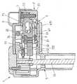
도 1 은 본 발명의 실시형태에 따른 시린지 펌프 구동 헤드의 단면도를 도시한다.
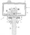
도 2 는 다른 관점으로부터의 도 1 에 따른 구동 헤드의 단면도를 도시한다.
도 3 은 도 1 의 구동 헤드의 부품의 확대도를 도시한다.
도 4 는 도 3 의 부품의 다른 도면이다.
도 5 는 도 1 의 구동 헤드의 다른 확대도를 도시한다.
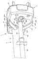
도 6 은 도 1 내지 도 5 에 따른 구동 헤드의 내부의 사시도이다.
도 7 내지 도 11 은 구동 헤드의 추가의 도면을 도시한다.1 shows a cross-sectional view of a syringe pump drive head according to an embodiment of the invention.
2 shows a sectional view of the drive head according to FIG. 1 from another perspective.
3 shows an enlarged view of a part of the drive head of FIG. 1.
4 is another view of the part of FIG. 3.
FIG. 5 shows another enlarged view of the drive head of FIG. 1.
6 is a perspective view of the inside of the drive head according to FIGS. 1 to 5.
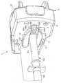
7-11 show further views of the drive head.
도 1 에 도시된 본 발명에 따른 시린지 펌프 구동 헤드 (1) 는, 구동 헤드의 작동시에 시린지 (미도시) 를 향해 적어도 부분적으로 대면하는 전방 부분 (21), 및 후방 부분 (22) 으로 이루어지는 하우징 (2) 을 포함한다.The syringe
구동 헤드의 접촉부 (3) 는 전방 하우징 부분 (21) 의 전방 측벽에 배치된다. 접촉부 (3) 는 시린지로부터 액체를 배출하기 위하여 시린지의 플런저의 플랜지에 대해 밀리고 시린지의 배럴에 대해 플런저를 이동시키도록 구성된다. 시린지 펌프의 작동 중에, 구동 헤드는 나사 구동 메커니즘의 축 (51) 을 따라 접촉부 (3) 의 선형 이동을 발생시키는 나사 구동 메커니즘을 포함하는 이동 메커니즘 (5) 을 통해 이동된다.The
구동 헤드 (1) 는 회전가능한 안티-사이펀 아암 (41, 42) 형태의 두 개의 유지 요소를 추가로 포함하고, 도 1 은 단지 상기 아암 중 하나의 일부를 도시한다. 양자의 아암은 예를 들어 도 4 에 도시되어 있다.The
아암 (41, 42) 은 플런저의 사이펀 이동, 즉 접촉부 (3) 로부터 멀어지는 이동을 방지하기 위해 시린지 플런저의 플랜지에 맞물리도록 구성된다. 이를 위해, 아암들 (41, 42) 각각은 파지 요소 (411, 421) 및 상기 파지 요소 (411, 421) 에 연결된 샤프트 (412, 422) 를 포함하고, 파지 요소 (411, 421) 는, 아암 (즉, 파지 요소) 이 시린지 플런저의 플랜지에 맞물리지 않는 개방 위치와, 아암이 플랜지에 맞물리는 폐쇄 위치 사이에서 샤프트 (412, 422) 를 통해 회전될 수 있고, 그리고 예를 들어 구동 헤드의 접촉부 (3) 와 접촉 상태에 있는 플런저 플랜지를 유지시킬 수 있다.The
구동 헤드 (1) 는 시린지의 내부 압력을 결정하기 위해 스트레인 게이지 (6; 도 1 에서는 보이지 않음) 형태의 압력 센서를 추가로 포함한다. 스트레인 게이지 (6) 는 하우징 (2) 내에 배치되는 압력 센서 지지체 (7) 에 부착된다. 압력 센서 지지체 (7) 는, 차례로, 시린지 플런저에 의해 접촉부 (3) 상에 가해진 힘이 압력 센서 지지체 (7) 를 통해 스트레인 게이지 (6) 에 전달되도록 배치되고 구성된다. 즉, 베어링 섹션 (3) 에 가해진 힘, 따라서 시린지의 내부 압력은 스트레인 게이지 (6) 에 의해 발생하는 전기 신호를 이용하여 측정될 수 있다. 스트레인 게이지가 이 실시형태에서 압력 센서로서 사용되지만, 다른 적합한 압력 센서도 이용될 수 있다.The
안티-사이펀 아암 (41, 42) 의 샤프트 (412, 422) 는 압력 센서 지지체 (7) 를 통해 장착된다. 특히, 압력 센서 지지체 (7) 는 스트레인 게이지가 부착되는 제 1 부분 (71) 및 샤프트 (412, 422) 가 장착되는 아암 마운트 (72) 형태의 제 2 부분을 포함한다. 제 1 부분 (71) 은 나사 (75) 를 통해 아암 마운트 (72) 에 연결된다.The
샤프트 (412, 22) 는 아암 마운트 (72) 에 의해 형성된 개구 (721, 722) 및 전방 하우징 부분 (21) 의 개구 (211, 212) 를 통해 뻗어 있다. 추가로, 샤프트 (412, 422) 는 이하에서 추가로 더 상세하게 설명될 수 있는 바와 같은 아암 (41, 42) 의 회전 이동을 발생시키기 위한 수단에 연결된다.The
뿐만 아니라, 샤프트 (412, 422) 는 아암 마운트 (72) 를 통해 단독으로 장착되고, 즉 샤프트 (412, 422) 는 전방 하우징 부분 (21) 의 개구 (211, 212) 를 통해 뻗어있지만, 구동 헤드의 작동 중에 개구 (211, 212) 의 내부 에지에 대해 놓여 있지 않다 ("부동 장착된" 아암). 따라서, 이러한 아암의 이동으로 인해 압력 센서 신호의 교란이 감소하거나 완전히 회피되도록 아암 (41, 42) 의 이동이 구동 헤드의 작동 중에 스트레인 게이지 (6) 를 향해 접촉부에 전달되는 것을 회피해야 한다.In addition, the
도 2 및 도 3 에서 가장 잘 도시된 바와 같이, 접촉부 (3) 는 구동 헤드의 작동시에 시린지 플런저 플랜지의 단부면이 지탱될 접촉 요소 (31) 를 포함한다. 접촉 요소 (31) 는 (도 3 에서 도시된 바와 같이) 타원형의 기본 섹션 및, 플런저 플랜지 단부면과 기계적인 접촉 상태에 있을 이 기본 섹션으로부터 (즉, 전방 하우징 부분 (21) 으로부터) 돌출하는 길이방향 돌출부 (311) 를 포함한다.As best shown in FIGS. 2 and 3, the
접촉 요소 (31) 는 링 형상의 멤브레인 (32) 형태의 가요성 (그리고 탄성) 요소를 통해 하우징 (2) 의 전방 부분 (21) 에 장착된다. 멤브레인 (32) 은 한편으로는 접촉 요소 (31) 에 연결되고 (예를 들어, 접착 결합되고), 다른 한편으로는 전방 하우징 부분 (21) 에 연결되며, 하우징 부분 (21) 과 접촉 요소 (31) 에 대한 멤브레인 (32) 의 연결은 밀봉 연결일 수 있다. 또한, 접촉부 (31) 의 이동이 가능한 한 정확하게 압력 센서 지지체 (7) 를 향해, 따라서 스트레인 게이지 (6) 를 향해 전달될 수 있도록, 멤브레인의 재료 및 멤브레인의 두께는 선택될 수 있다.The
또한 도 2 에 도시된 바와 같이, 압력 센서 지지체 (7) 는 단지 단일 연결 지점을 통해 하우징 (2; 즉, 전방 하우징 부분 (21)) 에 연결되고, 연결 지점은 나사 (73) 에 의해 실현된다. 나사 대신에 단일 연결 지점을 실현하기 위한 다른 수단, 예를 들어 래칭 연결 또는 접착 결합이 가능한 것에 주목한다. 단지 단일 연결 지점을 제공함으로써, 하우징 및 압력 센서는 하우징의 변형이 압력 센서에 전달되는 것을 회피하기 위하여 가능한 한 많이 결합해제된다.As also shown in FIG. 2, the
뿐만 아니라, 구동 헤드 (1) 는 캐리어 플레이트 (91) 에 배치되는 구형 요소 (9) 형태의 압력 전달 요소를 포함한다. 캐리어 플레이트 (19) 및 따라서 구형 요소 (9) 는 센서 지지체 (7) 의 제 1 부분 (71) 에 대해 구형 요소 (9) 의 섹션을 밀어낼 수 있도록 접촉부 (3) 에 대해 시린지 플런저가 가압하는 때에 이동될 것이다. 그러므로, 접촉부 (3) 에 가해진 힘은 플레이트 (91), 구형 요소 (9) 및 지지 부분 (71) 을 통해 스트레인 게이지 (6) 를 향해 전달될 것이다. 베어링 섹션 (3) 이 이동되는 (편향되는) 경우, 캐리어 플레이트 (91) 가 압력 센서 지지체 (7) 를 향해 피벗 이동을 실행하고, 이로 인해 압력 센서 지지체 (7) 에 대해 구형 요소 (9) 를 밀어낼 수 있도록 캐리어 플레이트 (91) 는 하우징 (2) 에 피벗 장착되는 것이 가능하다.In addition, the
도 3 은 도 1 및 도 2 의 구동 헤드 (1) 의 몇몇 부품의 확대 사시도를 도시한다. 아암 (41, 42) 이 도 3 에서 전방 하우징 부분 (21) 의 내부 측면 상에 도시되지만, 구동 헤드의 조립된 상태에서, 파지 요소 (411, 421) 는 전방 하우징 부분 (21) 의 외측에 위치될 것이고 샤프트 (412, 421) 는 하우징 부분 (21) 의 개구 (211, 212) 를 통해 연장할 것은 자명하다.FIG. 3 shows an enlarged perspective view of some parts of the
아암 (41, 42) 의 샤프트 (412, 422) 는 압력 센서 지지체 (7) 의 아암 마운트 (72) 의 개구 (721, 722) 에 장착된다. 개구 (721, 722) 의 일부는 아암 마운트 (72) 의 기본 부분으로부터 돌출하는 중공 원통형 부분에 의해 형성되고, 샤프트 (412, 422) 는 아암 (41,42) 의 회전 이동 및 축방향 이동을 발생시키는 수단 (8) 을 향하여 중공 원통형 부분을 통해 뻗어있다. 수단 (8) 은 아암 마운트 (72) 를 통해 부분적으로 뻗어있을 수 있고 샤프트 (412, 422) 에 연결되는 축선 (81, 82) 을 포함한다.The
추가로, 축선 (81, 82) 은 회전가능한 연결부가 축선 (81, 82) 사이에서 확립되도록 기어 휠 세그먼트 (83, 84) 에 연결된다. 추가로, 연결 아암 (85, 86) 은 축선 (81, 82) 으로부터 연장하고, 여기서 연결 아암 (85, 86) 의 자유 단부는 안티-사이펀 아암 (41, 42) 이 폐쇄 위치에 남아있는 경향이 있도록 연결 아암 (85, 86) 을 편향시키는 스프링 (87) 에 연결된다. 수단 (8) 의 원리는 도 4 내지 도 6 을 참조하여 더 상세하게 설명될 것이다.In addition, the
도 4 는 도 3 에 도시된 부품의 다른 사시도를 도시하고, 여기서 스트레인 게이지 (6) 는 센서 지지체 (7) 의 제 1 부분 (71) 의 후방면 (711) 에 연결되는 것이 보여질 수 있다. 추가로, 스트레인 게이지 (6) 를 예를 들어 센서 신호 (미도시) 를 평가하기 위한 수단 및/또는 전압 공급기에 연결하는 케이블 (61) 이 도시된다. 후방면 (711) 은 제 1 지지체 부분 (71) 의 전방면 (712) 에 평행하게 연장한다. 후방면 및 전방면 (711, 712) 모두는 각각 센서 지지체 (7) 를 하우징 (2) 에 연결하도록 그리고 아암 마운트 (72) 를 제 1 센서 지지체 부분 (71) 에 연결하도록 나사 (73, 74) 가 연장되는 연결 부분을 제공하기 위하여 노치 (7111, 7121) 를 포함한다.FIG. 4 shows another perspective view of the part shown in FIG. 3, where it can be seen that the
뿐만 아니라, 제 1 지지체 부분 (71) 은 후방면 및 전방면 (711, 712) 에 본질적으로 평행하게 연장하는 관통 개구 (713) 를 포함한다. 관통 개구 (713) 는 두 개의 중첩 원으로 이루어지는 (후방면 및 전방면 (711, 712) 에 대해 수직으로 연장하는 면을 따르는) 단면을 가지고, 원의 중심은 후방면 및 전방면 (711, 712) 에 평행하게 연장하는 라인을 따라 위치된다. 전방면 (712) 이 베어링 섹션 (3) 을 통해 가해진 부하 하에서 변형되는 경우, 후방면 (711) 이 유사한 방식으로 변형되고, 그 결과 지지부 (71) 가 변형되더라도 후방면 및 전방면 (711, 712) 이 여전히 서로 평행하게 연장하는 것은 관통 개구 (713) 의 이러한 설계 때문이다.In addition, the
특히, 아암 마운트 (72) 를 향하여 대면하는 관통 개구 (713) 측에 그리고 아암 마운트 (72) 로부터 멀어지게 대면하는 측에 각각 위치되는 후방면 및 전방면 (711, 712) 의 섹션들은, 힘이 전방면 (711) 에 가해질지라도, 서로에 평행하게 그리고 후방면 및 전방면 (711, 712) 이 (지지부 (71) 의 변형 이전에) 원래대로 연장되는 면에 평행하게 여전히 연장될 것이다. 이는 센서 지지부 (71) 가 변형하는 경우, 관통 개구 (713) 에 대해 측방향으로 위치되는 지지부 (71) 의 섹션에 연결되는 아암 마운트 (72) 가 경사지지 않는 효과를 가진다. 오히려, 이는 아암 (41, 42) 이 시린지 플런저 플랜지에 대해 경사지지 않고 (또는 적어도 단지 약간 경사지지 않고) 시린지 축을 따라서 단지 이동될 수 있도록 구동 헤드의 이동 방향을 따라 단지 변위될 수 있다.In particular, the sections of the rear and
게다가, 회전 이동 및 축방향 이동을 발생시키는 수단 (8) 은 아암 (41, 42) 의 회전 이동뿐만 아니라, 시린지가 구동 헤드에 배치되는 때에 아암을 전방 하우징 부분 (21) 으로부터 멀리 일정 거리를 이동시킬 수 있도록 선형 이동을 발생시킬 수 있다. 도 4 에 도시된 바와 같이, 다른 스프링 (88) 은 아암 마운트 (72) 와 하부 연결 아암 (85) 사이에 제공되고, 스프링 (88) 은 후방 위치에서 아암을 유지하는 경향이 있다. 따라서, 스프링 (88) 은 안티-사이펀 아암 (41, 42) 이 접촉부 (3) 와 접촉 상태에 있는 시린지 플런저를 유지시키는 후방 위치를 향해 복귀하는 경향이 있도록 하부 연결 아암 (85) 에 (그리고 이러한 아암이 상부 연결 아암 (86) 에 연결되는 때에, 상부 연결 아암에) 리셋 힘을 가할 것이다.In addition, the
도 5 및 도 6 은 안티-사이펀 아암 (41, 42) 의 회전 이동 및 축방향 이동을 발생시키는 수단 (8) 의 부품을 더 상세하게 설명한다.5 and 6 illustrate in more detail the parts of the
수단 (8) 은 하우징 (2) 외측에 배치되는 레버 (800) 를 포함하는 작동 장치 (850) 를 구비한다. 레버 (800) 는 하우징의 측벽을 통해 하우징 (2) 의 내부에 위치되는 트랜스미션 부품 (810) 에 연결된다. 따라서, 레버 (800) 의 회전은 트랜스미션 부품 (810) 을 또한 회전시킬 것이다 (즉, 트랜스미션 부품 (810) 은 레버의 회전을 따를 것이다).The
뿐만 아니라, 수단 (8) 은 트랜스미션 부품 (810) 의 돌기부 (830) 형태의 제 1 상호작용 요소 (즉, 돌기부 (830) 는 작동 장치 (850) 에 일체로 연결됨) 및 하부 연결 아암 (85) 에 연결되는 원통형 돌출부 (820) 형태의 제 2 상호작용 요소 (따라서, 돌출부 (820) 는 연결 아암 (85, 86) 과 아암 (41, 42) 사이의 연결부를 통해 안티-사이펀 아암 (41, 42) 에 간접적으로 연결됨) 를 포함한다.In addition, the
레버 (800) 가 시작 위치로부터 반시계 방향으로 회전되는 경우, 하부 연결 아암 (85) 및 상부 연결 아암 (86) 이 스프링 (87) 의 편향력에 대해 회전되도록 돌출부 (820) 에 대해 돌기부 (830) 를 밀어낼 것이다. 연결 아암의 회전에 의해, 안티-사이펀 아암 (41, 42) 은 레버 (800) 를 반시계 방향으로 회전시킴으로써 아암 (41, 42) 이 폐쇄 위치로부터 아암 사이의 거리가 폐쇄 위치에서보다 더 큰 개방 위치로 회전될 수 있도록 또한 회전될 것이다.When the
작동 메커니즘 (850) 은 하부 축 (81) 의 테이퍼링된 단부 (840) 형태의 추가의 (제 3 의) 상호작용 요소를 추가로 포함한다. 트랜스미션 부품 (810) 의 상호작용부 (845) 형태의 제 4 의 상호작용 요소는 테이퍼링된 단부 (840) 에 할당되고, 여기서 하부 축 (81) 및 연결된 상부 축 (82) 이 후방 위치에서 전방 위치를 향해 축선 방향으로 (구동 헤드의 이동 방향을 따라) 이동될 수 있도록 레버가 반시계 방향으로 피봇 회전되는 때에 테이퍼링된 단부 (840) 에 대해 상호작용부 (845) 를 밀어낼 것이다.The
축선 (81, 82) 의 선형 이동 이후에 안티-사이펀 아암 (41, 42) 은 축선 방향으로, 즉 접촉부 (3) 로부터 멀어져 전방 위치로 이동할 것이다. 따라서, 레버 (800) 를 회전시킴으로써, 안티-사이펀 아암 (41, 42) 은 제 1 위치 (폐쇄 아암, 접촉부 (3) 에 대하여 후방 위치) 로부터 제 2 위치 (개방 아암, 접촉부 (3) 에 대하여 전방 위치) 로 반경 방향으로 그리고 축선 방향으로 이동될 수 있다. 아암의 "전방 위치" 는 접촉부 (3) 로부터의 (즉, 하우징 (2) 으로부터의) 거리가 "후방 위치" 에서보다 더 크다는 것을 의미한다.After linear movement of the
구동 헤드 (1) 는 아암이 레버 (800) 를 회전시킴으로써 개방 및 전방 위치에서 이동된 후에 아암 (41, 42) 을 잠그는 래칭 메커니즘을 추가로 포함한다. 래칭 메커니즘은 체결 요소 (92) 를 포함하고, 개방 및 전방 위치에서 레버 (800) 를 회전시킨 후에, 체결 요소 (92) 의 돌기부 (921) 는 아암 (41, 42) 이 개방 및 전방 위치에서 잠겨지도록 상부 아암 (42) 의 샤프트 (422) 에 제공된 그루브 (4221, 도 3) 와 맞물린다. 또한, 레버 (800) 가 스프링 (89) 을 통해 편향되므로, 아암 (41, 42) 이 개방 위치에서 잠기는 경우, 레버 (800) 는 시작 위치로 복귀할 것이다. 레버 (800) 의 시작 위치에서, 돌기부 (830) 및 상호작용부 (845) 는 아암 (41, 42) 이 트랜스미션 부품 (810) 및 레버 (800) 로부터 결합해제되도록 테이퍼링된 단부 (840) 및 돌출부 (820) 각각과 더 이상 접촉 상태에 있지 않다.The
체결 요소 (92) 는 플레이트 캐리어 (91) 의 섹션 (93) 에 유지되고, 캐리어 플레이트는 접촉 요소 (31) 에 대해 시린지 플런저를 밀어내는 경우 하우징 (2) 으로부터 멀리 이동될 것이다. 따라서, 체결 요소는 또한 이동되고, 아암 (41, 42) 이 더 이상 잠겨지지 않도록 잠금 위치로부터 해제된다. 시린지가 구동 헤드로부터 제거되는 경우, 접촉 요소는 주변 멤브레인 (32) 의 탄성으로 인해 외부 위치로 다시 복귀될 것이다. 스프링은 대신 사용될 수 있거나 멤브레인에 더하여 사용될 수 있다.The
하지만, 설명된 래칭 메커니즘이 단지 선택적이라는 것이 주목된다. 또한, 예컨대 구동 헤드에서의 시린지의 배열 동안 "개방" 위치에서 레버 (800) 를 유지시킴으로써 아암 (41, 42) 이 개방 위치에서 수동으로 유지되는 것이 가능하다. 시린지가 배치된 후에, 레버 (800) 는 아암 (41, 42) 이 폐쇄 및 후방 위치로 되튕기도록 해제된다.However, it is noted that the described latching mechanism is merely optional. It is also possible for the
도 7 및 도 8 은 구동 헤드 (1) 의 추가의 도면을 도시하고, 시린지 (500) 는 구동 헤드에 배치되도록 도시되고, 시린지 (500) 는 플런저 (501) 를 포함한다. 도 7 에 도시된 바와 같은 통상의 시린지 플런저는 주요 부분 (5011) 및 주요 부분의 단부에 배치되는 플랜지 (502) 를 포함하고, 플랜지는 주요 부분으로부터 돌출하며, 즉 플랜지 (502) 는 플런저 주요 부분 (5011) 보다 더 큰 직경을 갖는다.7 and 8 show further views of the
시린지 플런저 (501) 의 플랜지 (502) 의 단부면이 구동 헤드의 접촉부 (3) 에 대해 지탱하도록 시린지는 구동 헤드에 배치되고, 그 결과 접촉부 (3) 가 이동되는 때에 액체가 시린지로부터 배출되도록 플런저 (501) 는 시린지 (500) 의 배럴 (503) 내에서 이동될 것이다.The syringe is placed in the drive head such that the end face of the
전술한 바와 같이, 구동 헤드는 아암을 개방 및 전방 위치 ("제 2 위치", 도 7) 로부터 폐쇄 및 후방 위치 ("제 1 위치", 도 8) 로 이동시키기 위하여 안티-사이펀 아암 (41, 42) 의 회전 이동 및 축방향 이동을 발생시키는 수단 (8) 을 포함한다. 구동 헤드에 시린지를 배열시킨 후에, 파지 요소 (411, 412) 가 플랜지 (502) 의 주변 에지 (5021) 에 대해 지탱하도록 아암 (41, 42) 은 제 1 위치로, 즉 폐쇄 및 후방 위치로 되튕겨질 것이다.As mentioned above, the drive head is adapted to move the arm from the open and front position (“second position”, FIG. 7) to the closed and rear position (“first position”, FIG. 8)
게다가, 파지 요소 (411, 421) 각각은 제 1 섹션 (400a, 400b) 및 제 1 섹션을 넘어서 돌출하는 제 2 섹션 (401a, 401b) 을 포함하고, 아암 (41, 42) 의 폐쇄 및 후방 위치에서, 파지 요소 (411, 421) 의 제 1 섹션 (400a, 400b) 만이 플랜지 (502) 의 주변 에지 (5021) 에 대해 지탱하는 반면, 제 2 섹션 (401a, 401b) 은 주변 에지 (5021) 에 대해 지탱하지 않고 접촉부 (3) 로부터 멀어지게 대면하는 플랜지 (502) 의 전방면 (전방측; 5022) 에 대해 놓인다.In addition, each of the
하지만, 제 2 섹션 (401a, 401b) 은 아암 (41, 42) 의 폐쇄 및 후방위치에서 플랜지 전방면 (5022) 에 대해 놓이지 않을 수 있다는 것이 주목된다. 이러한 경우에, 제 2 섹션 (401a, 401b) 은 전방면 (5022) 으로부터 거리를 두고 위치되지만 여전히 아암 (41, 42) 의 사이펀 이동을 차단하도록, 즉 플런저 플랜지와 여전히 "맞물리도록" 위치된다.However, it is noted that the
도 9a 및 도 9b 는 구동 헤드 (1) 의 부분도를 도시하고, 도 9a 에 따라, 아암 (41, 42) 은 폐쇄 위치에 있지만, 가장 후방 위치에 아직 도달되지 않았다. 아암 (41, 42) 이 (도 9a 에서 도시된 바와 같이) 플랜지 (502) 의 주변 에지 (5021) 에 대해 지탱할 때까지 수단 (8) 에 의해 (즉, 스프링 (87 ~ 89) 의 리셋 힘을 통해) 회전된 후에, 아암 (41, 42) 이 도 9b 에서 도시된 바와 같이 플랜지 (502) 의 내부면 (5022) 에 대해 지탱할 때까지 아암의 후방 이동은 (스프링 (87 ~ 89) 의 리셋 힘에 의해) 시작되거나 계속된다.9A and 9B show a partial view of the
이러한 예에서, 회전 이동 및 축방향 이동은 적어도 부분적으로 연속적으로 행해진다. 이러한 순차적인 이동을 발생시키기 위하여, (폐쇄 위치를 향해 아암의 회전 이동을 발생시키는) 스프링 (87) 및 (후방 위치를 향해 아암의 선형 이동을 발생시키는) 스프링 (88) 이 따라서 적합하다. 예를 들어, 스프링 87 은 스프링 88 보다 더 높은 스프링 상수를 갖는다.In this example, the rotational movement and the axial movement are at least partially continuous. To generate this sequential movement, springs 87 (which generate a rotational movement of the arm towards the closed position) and springs 88 (which generate a linear movement of the arm towards the rear position) are thus suitable. For example,
하지만, (제 2 위치로부터 제 1 위치로의) 아암의 회전 이동 및 축방향 이동이 동시에 (또는 적어도 본질적으로 동시에) 행해지는 것이 가능하다는 것이 주목된다.However, it is noted that the rotational movement and the axial movement of the arm (from the second position to the first position) can be done simultaneously (or at least essentially simultaneously).
추가로 아암이 후방 위치에서 이동되기 이전에 폐쇄 위치에서 회전되더라도 아암이 플랜지 (502) 를 통과하는 것을 회피되도록 전방 위치에서 접촉부 (3) 로부터의 아암 (41, 42) 의 거리가 플런저 플랜지 (502) 의 두께보다 더 작다는 것이 주목된다. 따라서, 폐쇄 위치에 있는 아암이 플랜지 (502) 의 주변 에지 (5021) 에 대해 지탱할 수 있다는 것이 보장된다.Additionally, the distance of the
파지 요소 (411, 421) 의 제 2 섹션 (401a, 401b) 은 "핑거" (4011a, 4011b) 가 제 1 섹션 (400a, 400b) 의 내부면 (4001a, 4001b) 을 넘어 돌출하도록 제 1 섹션 (400a, 400b) 을 넘어 연장한다. 핑거 (4011a, 4011b) 의 길이는 파지 요소의 제 1 섹션 (400a, 400b) 의 내부면 (4001a, 4001b) 이 플랜지 (502) 의 주변 에지 표면 (5021) 에 대해 지탱하는 반면, 제 2 섹션 (401a, 401b) 이 플런저의 주요 부분 (5011) 과 접촉 상태에 있지 않도록 플런저 플랜지 (502) 의 높이보다 더 작다.The
핑거 (4011a, 4011b) 가 제 1 섹션 (400a, 400b) 의 내부면 (4001a, 4001b) 에 수직하게 배치되므로, 에지는 제 1 섹션과 제 2 섹션 사이에 형성되고, 플런저 축에 대해 수직하게 본 에지는 파지 요소 (411, 412) 의 전체 길이를 따라 본질적으로 연장한다. 추가로, 핑거 (4011a, 4011b) 는 플런저 (501) 를 향해 약간 테이퍼링되고, 테이퍼링은 핑거 (4011a, 4011b) 의 전방측 부분의 굽힘에 의해 실현된다.Since the
(아암 (41, 42) 의 개방 위치에 관한) 도 10 및 (폐쇄 위치에 관한) 도 11 은 도 7 및 도 8 에 해당하는 사시도를 각각 제공하고, 도 11 에 따라서 아암은 폐쇄 위치에 있지만 아직 가장 후방 위치에 있지 않다. 압력 센서 (6) 와 베어링 부분 (3) 의 핑거 (31) 사이에 배치된 캐리어 플레이트 (91) 는 핑거 (31) 에 가해진 힘이 지지 플레이트 (91) 를 회전시키도록 하우징의 힌지 부분에 장착될 수 있고, 그 결과 지지 플레이트 (91) 의 회전 이동에 의해 압력 센서 장치 (6) 에 대해 구형 요소 (9) 를 밀어내는 것을 볼 수 있다.FIG. 10 (relative to the open positions of the
도 7 내지 도 9 를 참조하여 설명된 (제 1 위치에서 플랜지의 주변 에지에 대해 지탱하도록 아암을 이동시키는) 수단 (8) 의 원리는 임의의 종류의 시린지 펌프 구동 헤드와 사용될 수 있다는 것이 주목된다. 특히, 아암 (41, 42) 을 플랜지의 주변 에지에 대해 지탱할 수 있는 원리는 도 1 내지 도 6 을 참조하여 설명된 바와 같이 아암 (41, 42) 을 부동 장착시키는 개념으로부터 독립적으로 사용될 수 있고, 즉 아암 (41, 42) 을 플랜지의 주변 에지에 대해 지탱할 수 있는 원리는 예를 들어 구동 헤드 하우징을 통해 통상적으로 장착되는 유지 요소와 연계하여 또한 사용될 수 있다.It is noted that the principle of the means 8 (moving the arm to bear against the peripheral edge of the flange in the first position) described with reference to FIGS. 7 to 9 can be used with any kind of syringe pump drive head. . In particular, the principle of supporting the
1구동 헤드
2하우징
3접촉부
5이동 메커니즘
6스트레인 게이지
7압력 센서 지지체
8회전 이동 및 축방향 이동을 발생시키기 위한 수단
9구형 요소
21전방 부분
22후방 부분
31접촉부
32멤브레인
41제 1 아암
42제 2 아암
51축
61케이블
71제 1 부분
72아암 마운트
73, 74나사
81, 82축
83, 84기어 휠 세그먼트
85, 86아암
87, 88, 89스프링
91캐리어 플레이트
92체결 요소
93래칭 구조체
211, 212관통 개구
311돌출부
400a, 400b제 1 섹션
401a, 401b제 2 섹션
411, 421파지 요소
412, 422샤프트
500시린지
501플런저
502플랜지
503배럴
711후방면
712전방면
713관통 개구
721, 722개구
800레버
810트랜스미션 부품
820돌출부
830돌기부
840테이퍼링된 단부
845상호작용부
850작동 장치
4001a, 4001b내부면
4011a, 4011b핑거
4221그루브
5011주요 부분
5021주변 에지
5022전방면
7111, 7121노치1 driven head
2 housing
3 contact
5 moving mechanism
6 strain gauge
7 pressure sensor support
Means for generating eight rotational and axial movements
9 spherical elements
21 front section
22 rear part
31 contacts
32 membrane
41st arm
42 2nd arm
51 axes
61 cables
71 first part
72 arm mount
73, 74 screws
81, 82 axes
83, 84 gear wheel segment
85, 86 arm
87, 88, 89 spring
91 carrier plate
92 fastening elements
93 Latching Structure
211, 212 through opening
311 overhang
400a, 400b first section
401a, 401b second section
411, 421 gripping elements
412, 422 shaft
500 syringes
501 plunger
502 flange
503 barrel
711 rear view
712 front
713 through opening
721, 722 opening
800 lever
810 Transmission Parts
820 protrusions
830 protrusion
840 tapered ends
845 Interactions
850 operating unit
4001a, 4001b internal surface
4011a, 4011b finger
4221 groove
5011 main parts
5021 peripheral edge
5022 front
7111, 7121 notch
Claims (15)
Translated fromKorean플런저를 시린지의 배럴에 대해 이동시키기 위해 상기 시린지의 플런저에 대해 지탱되도록 형성된 접촉부 (3);
상기 접촉부 (3) 로부터 멀어지는 상기 플런저의 사이펀 이동을 방지하기 위해 시린지 플런저의 플랜지를 유지하는 적어도 하나의 유지 요소 (41, 42);
상기 시린지의 내부 압력을 결정하기 위한 압력 센서 (6) 로서, 상기 구동 헤드 (1) 의 압력 센서 지지체 (7) 에 배치된 상기 압력 센서 (6); 및
상기 압력 센서 (6) 및 상기 압력 센서 지지체 (7) 가 안에 배치되는 하우징 (2) 을 포함하고,
상기 유지 요소 (41, 42) 는 상기 압력 센서 지지체 (7) 를 통해 장착되는 것을 특징으로 하는 시린지 펌프용 구동 헤드.As a drive head for a syringe pump,
A contact portion (3) formed to bear against the plunger of the syringe to move the plunger relative to the barrel of the syringe;
At least one retaining element (41, 42) holding a flange of the syringe plunger to prevent siphon movement of the plunger away from the contact (3);
A pressure sensor (6) for determining the internal pressure of the syringe, comprising: the pressure sensor (6) disposed on the pressure sensor support (7) of the drive head (1); And
A housing 2 in which the pressure sensor 6 and the pressure sensor support 7 are disposed,
Drive element for a syringe pump, characterized in that the retaining element (41, 42) is mounted via the pressure sensor support (7).
상기 압력 센서 지지체 (7) 는 상기 구동 헤드 (1) 의 작동시에 상기 시린지로부터 멀어지게 대면하는 접촉부 (3) 측에 배치되는 것을 특징으로 하는 시린지 펌프용 구동 헤드.The method of claim 1,
The drive head for a syringe pump, characterized in that the pressure sensor support (7) is arranged on the side of the contact portion (3) facing away from the syringe during operation of the drive head (1).
상기 압력 센서 지지체 (7) 는 상기 접촉부 (3) 상에 상기 시린지 플런저에 의해 가해진 힘이 상기 압력 센서 지지체 (7) 를 통해 상기 압력 센서 (6) 에 전달되도록 배치되는 것을 특징으로 하는 시린지 펌프용 구동 헤드.3. The method according to claim 1 or 2,
The pressure sensor support 7 is arranged for the syringe pump, characterized in that the force exerted by the syringe plunger on the contact portion 3 is transmitted to the pressure sensor 6 via the pressure sensor support 7. Driving head.
상기 압력 센서 (6) 는 상기 접촉부 (3) 로부터 멀어지게 대면하는 압력 센서 지지체 (7) 측 (711) 에 배치된 적어도 하나의 스트레인 게이지를 포함하는 것을 특징으로 하는 시린지 펌프용 구동 헤드.The method according to any one of claims 1 to 3,
The drive head for a syringe pump, characterized in that the pressure sensor (6) comprises at least one strain gauge arranged on the side of the pressure sensor support (7) facing away from the contact portion (3).
상기 압력 센서 지지체 (7) 의 전방측 (712) 및 후방측 (711), 및
상기 전방측 (712) 및 후방측 (711) 에 대해 평행하게 연장하는 관통 개구 (713) 를 포함하고,
상기 관통 개구 (713) 는, 상기 구동 헤드의 이동 방향에 대해 수직한 방향에서 보았을 때에 상기 관통 개구 (713) 의 측방에 위치한 전방측 (712) 의 섹션에 베어링 섹션 (3) 이 힘을 인가하여, 상기 압력 센서 지지체가 상기 관통 개구 (713) 의 영역에서 변형되는 한편, 상기 관통 개구 (713) 의 측방에 위치한 전방측 및 후방측 (712, 711) 의 섹션들이 단지 인가된 힘의 방향을 따라 변위되어, 상기 섹션들이 힘의 인가 이전에 연장되는 평면에 대해 평행하게 여전히 연장되도록 형성되고 배치되는 것을 특징으로 하는 시린지 펌프용 구동 헤드.5. The method of claim 4,
The front side 712 and the rear side 711 of the pressure sensor support 7, and
A through opening 713 extending parallel to the front side 712 and the rear side 711,
The through opening 713 applies a force to the bearing section 3 to a section of the front side 712 located to the side of the through opening 713 when viewed in a direction perpendicular to the moving direction of the drive head. Wherein the pressure sensor support is deformed in the region of the through opening 713, while the sections of the front and rear sides 712, 711 located to the side of the through opening 713 only along the direction of the applied force. A drive head for a syringe pump, characterized in that it is displaced so that the sections are still extended parallel to the plane extending before the application of the force.
상기 접촉부 (3) 는 상기 하우징 (2) 의 섹션에 배치되는 것을 특징으로 하는 시린지 펌프용 구동 헤드.6. The method according to any one of claims 1 to 5,
Drive head for a syringe pump, characterized in that the contact portion (3) is arranged in a section of the housing (2).
상기 접촉부 (3) 는, 상기 구동 헤드 (1) 의 작동시에 상기 시린지 플런저가 접촉 요소 (31) 에 대해 지탱하도록 배치된 접촉 요소 (31) 를 포함하고, 상기 접촉 요소 (31) 는 가요성 요소 (32) 를 통해 상기 하우징 (2) 에 장착되는 것을 특징으로 하는 시린지 펌프용 구동 헤드.The method according to claim 6,
The contact part 3 comprises a contact element 31 arranged such that the syringe plunger bears against the contact element 31 when the drive head 1 is operated, the contact element 31 being flexible. Drive head for a syringe pump, characterized in that it is mounted to the housing (2) via an element (32).
상기 하우징 (2) 은 개구 (211, 212) 를 포함하고, 상기 유지 요소 (41, 42) 는 상기 개구 (211, 212) 의 내부 에지에 대해 거리를 갖고서 상기 개구 (211, 212) 를 통해 연장하는 것을 특징으로 하는 시린지 펌프용 구동 헤드.8. The method according to any one of claims 1 to 7,
The housing 2 comprises openings 211, 212, and the retaining elements 41, 42 extend through the openings 211, 212 with a distance to the inner edge of the openings 211, 212. Drive head for syringe pump, characterized in that.
상기 유지 요소 (41, 42) 는 상기 압력 센서 지지체 (7) 에 회전가능하게 장착되는 것을 특징으로 하는 시린지 펌프용 구동 헤드.9. The method according to any one of claims 1 to 8,
The holding element (41, 42) is a drive head for a syringe pump, characterized in that it is rotatably mounted to the pressure sensor support (7).
상기 유지 요소 (41, 42) 는 상기 압력 센서 지지체 (7) 를 통해 적어도 부분적으로 뻗어있는 샤프트 (412, 422) 를 포함하는 것을 특징으로 하는 시린지 펌프용 구동 헤드.10. The method according to any one of claims 1 to 9,
The retaining element (41, 42) comprises a shaft (412, 422) at least partially extending through the pressure sensor support (7).
상기 시린지를 상기 구동 헤드에 배치하는데 사용될 수 있는 개방 위치로부터 상기 시린지가 상기 구동 헤드에 배치되는 경우에 상기 유지 요소 (41, 42) 가 상기 시린지 플런저의 플랜지를 유지하는 폐쇄 위치로 상기 유지 요소 (41, 42) 를 이동시키기 위하여 상기 유지 요소 (41, 42) 의 회전 이동 및/또는 축방향 이동을 발생시키는 수단 (8) 을 포함하는 것을 특징으로 하는 시린지 펌프용 구동 헤드.11. The method according to any one of claims 1 to 10,
The holding element (from the open position that can be used to place the syringe in the drive head from the open position to the closed position where the retaining elements 41, 42 hold the flange of the syringe plunger when the syringe is placed in the drive head); Means (8) for generating a rotational movement and / or an axial movement of said retaining element (41, 42) for moving said 41, 42.
상기 수단 (8) 은 상기 유지 요소 (41, 42) 를 이동시키기 위한 작동 장치 (850) 를 포함하고, 상기 작동 장치 (850) 는 상기 하우징 (2) 의 외측으로부터 수동으로 작동되도록 구성되고, 상기 유지 요소 (41, 42) 는 상기 작동 장치 (850) 를 시작 위치로부터 개방 위치로 이동시킴으로써 상기 폐쇄 위치로부터 상기 개방 위치로 이동가능하고, 상기 작동 장치 (850) 는 상기 시작 위치에서 상기 유지 요소 (41, 42) 로부터 결합해제되도록 구성된 것을 특징으로 하는 시린지 펌프용 구동 헤드.The method of claim 11,
The means 8 comprises an actuating device 850 for moving the retaining elements 41, 42, the actuating device 850 being configured to be operated manually from the outside of the housing 2, and The retaining elements 41, 42 are movable from the closed position to the open position by moving the actuating device 850 from the start position to the open position, and the actuating device 850 is moved from the retaining element ( 41, 42 drive head for a syringe pump, characterized in that configured to disengage from.
상기 수단 (8) 은 상기 시작 위치에서 상기 작동 장치 (850) 를 유지하는데 기여하는 탄성 수단 (89) 을 포함하는 것을 특징으로 하는 시린지 펌프용 구동 헤드.13. The method of claim 12,
The drive head for a syringe pump, characterized in that the means (8) comprise resilient means (89) which contribute to holding the operating device (850) in the starting position.
상기 수단 (8) 은 상기 작동 장치 (850) 에 연결된 제 1 상호작용 요소 (830) 및 상기 유지 요소 (41, 42) 에 연결된 제 2 상호작용 요소 (820) 를 포함하고, 상기 작동 장치 (850) 를 작동시키는 것에 의해 상기 제 1 상호작용 요소 (830) 가 상기 제 2 상호작용 요소 (820) 에 대해 푸싱될 수 있으며 그럼으로써 상기 유지 요소 (41, 42) 가 상기 개방 위치를 향하여 이동되는 것을 특징으로 하는 시린지 펌프용 구동 헤드.The method according to claim 12 or 13,
The means 8 comprises a first interaction element 830 connected to the actuating device 850 and a second interaction element 820 connected to the retaining elements 41, 42, the actuating device 850 Actuating the first interacting element 830 can be pushed relative to the second interacting element 820 such that the retaining elements 41, 42 are moved towards the open position. A drive head for a syringe pump, characterized in that.
상기 압력 센서 지지체 (7) 는 제 1 및 제 2 부분 (71, 72) 을 포함하고, 상기 제 2 부분 (72) 은 연결 수단 (74) 을 통해 상기 제 1 부분 (71) 에 연결되고, 상기 압력 센서 (6) 는 상기 제 1 부분 (71) 에 배치되고, 상기 유지 요소 (41, 42) 는 상기 제 2 부분 (72) 을 통해 장착되는 것을 특징으로 하는 시린지 펌프용 구동 헤드.15. The method according to any one of claims 1 to 14,
The pressure sensor support 7 comprises first and second parts 71, 72, the second part 72 being connected to the first part 71 via connecting means 74, and A pressure head (6) is arranged in the first part (71), and the retaining element (41, 42) is mounted via the second part (72).
Applications Claiming Priority (5)
| Application Number | Priority Date | Filing Date | Title |
|---|---|---|---|
| US201161453143P | 2011-03-16 | 2011-03-16 | |
| EP11158391.0 | 2011-03-16 | ||
| EP11158391 | 2011-03-16 | ||
| US61/453,143 | 2011-03-16 | ||
| PCT/EP2012/054282WO2012123417A1 (en) | 2011-03-16 | 2012-03-12 | Drive head for a syringe pump |
Publications (1)
| Publication Number | Publication Date |
|---|---|
| KR20140019798Atrue KR20140019798A (en) | 2014-02-17 |
Family
ID=44114328
Family Applications (1)
| Application Number | Title | Priority Date | Filing Date |
|---|---|---|---|
| KR1020137027228AWithdrawnKR20140019798A (en) | 2011-03-16 | 2012-03-12 | Drive head for a syringe pump |
Country Status (13)
| Country | Link |
|---|---|
| US (1) | US9731068B2 (en) |
| EP (1) | EP2686039B1 (en) |
| JP (1) | JP6134655B2 (en) |
| KR (1) | KR20140019798A (en) |
| CN (1) | CN103429284B (en) |
| AU (1) | AU2012228363B2 (en) |
| BR (1) | BR112013023329A2 (en) |
| CA (1) | CA2829514C (en) |
| IL (1) | IL228004A0 (en) |
| MX (1) | MX2013010569A (en) |
| RU (1) | RU2013146099A (en) |
| WO (1) | WO2012123417A1 (en) |
| ZA (1) | ZA201306266B (en) |
Families Citing this family (15)
| Publication number | Priority date | Publication date | Assignee | Title |
|---|---|---|---|---|
| US9744300B2 (en) | 2011-12-21 | 2017-08-29 | Deka Products Limited Partnership | Syringe pump and related method |
| US9295778B2 (en) | 2011-12-21 | 2016-03-29 | Deka Products Limited Partnership | Syringe pump |
| US9789247B2 (en) | 2011-12-21 | 2017-10-17 | Deka Products Limited Partnership | Syringe pump, and related method and system |
| US11217340B2 (en) | 2011-12-21 | 2022-01-04 | Deka Products Limited Partnership | Syringe pump having a pressure sensor assembly |
| US10722645B2 (en) | 2011-12-21 | 2020-07-28 | Deka Products Limited Partnership | Syringe pump, and related method and system |
| WO2014106008A1 (en) | 2012-12-28 | 2014-07-03 | Gambro Renal Products, Inc. | Syringe pump engagement detection apparatus and methods |
| CN104689425B (en)* | 2013-12-10 | 2017-09-12 | 深圳市科曼医疗设备有限公司 | Push handle gripping mechanism for the syringe of syringe pump |
| WO2015127189A1 (en) | 2014-02-21 | 2015-08-27 | Deka Products Limited Partnership | Syringe pump having a pressure sensor assembly |
| CN103948991B (en)* | 2014-04-25 | 2017-03-22 | 深圳圣诺医疗设备股份有限公司 | Injector clamping device |
| WO2017207165A1 (en)* | 2016-06-01 | 2017-12-07 | Fresenius Vial Sas | Infusion device and method allowing for detecting a drift in a sensor signal |
| CN109952120A (en) | 2016-12-09 | 2019-06-28 | 费森尤斯维尔公司 | Suitable for testing the infusion device of extravasation |
| JP7071846B2 (en)* | 2018-03-02 | 2022-05-19 | ミネベアミツミ株式会社 | Syringe pump |
| US11338072B2 (en)* | 2020-04-14 | 2022-05-24 | Fresenius Medical Care Holdings, Inc. | Blood treatment systems and related components and methods |
| EP4398959A1 (en) | 2021-09-10 | 2024-07-17 | Fresenius Vial SAS | Infusion device having a processing device configured to determine a value indicative of a sensitivity of a sensor device |
| US20240261497A1 (en) | 2023-02-02 | 2024-08-08 | Fresenius Kabi Usa, Llc | Infusion system with sensor system having reduced compliance sensitivity |
Family Cites Families (14)
| Publication number | Priority date | Publication date | Assignee | Title |
|---|---|---|---|---|
| GB8525109D0 (en) | 1985-10-11 | 1985-11-13 | Vickers Plc | Syringe pumps |
| DE3737331C1 (en) | 1987-11-04 | 1989-02-23 | Braun Melsungen Ag | Pressure infusion apparatus |
| US5254096A (en)* | 1992-09-23 | 1993-10-19 | Becton, Dickinson And Company | Syringe pump with graphical display or error conditions |
| US5261882A (en)* | 1993-04-26 | 1993-11-16 | Sealfon Andrew I | Negator spring-powered syringe |
| WO1998030260A1 (en) | 1997-01-10 | 1998-07-16 | Japan Servo Co., Ltd. | Liquid transportation apparatus |
| US6368307B1 (en)* | 1997-07-18 | 2002-04-09 | Liebel-Flarsheim Company | Front-loading power injector and method of loading flanged syringe therein |
| GB9915525D0 (en)* | 1999-07-03 | 1999-09-01 | Smiths Industries Plc | Syringe pumps |
| US6428509B1 (en) | 1999-07-29 | 2002-08-06 | Alaris Medical Systems, Inc. | Syringe plunger driver system and method |
| DE20200885U1 (en)* | 2002-01-22 | 2003-05-28 | B. Braun Melsungen Ag, 34212 Melsungen | Syringe pump with piston brake |
| US7150724B2 (en)* | 2002-06-05 | 2006-12-19 | Cardinal Health 303, Inc. | Syringe plunger driver system |
| US7666169B2 (en)* | 2003-11-25 | 2010-02-23 | Medrad, Inc. | Syringe and syringe plungers for use with medical injectors |
| FR2880809B1 (en)* | 2005-01-17 | 2007-02-23 | Fresenius Vial Soc Par Actions | RETENTION DEVICE FOR BLOCKING THE PISTON HEAD OF A SYRINGE ON THE PUSHER OF A SYRINGE PUSHER |
| US7905860B2 (en)* | 2008-09-05 | 2011-03-15 | Elixir Corp. | Plunger disc loading mechanism for syringe pump |
| US8378837B2 (en) | 2009-02-20 | 2013-02-19 | Hospira, Inc. | Occlusion detection system |
- 2012
- 2012-02-21USUS13/400,978patent/US9731068B2/enactiveActive
- 2012-03-12MXMX2013010569Apatent/MX2013010569A/ennot_activeApplication Discontinuation
- 2012-03-12RURU2013146099/14Apatent/RU2013146099A/ennot_activeApplication Discontinuation
- 2012-03-12EPEP12708330.1Apatent/EP2686039B1/enactiveActive
- 2012-03-12AUAU2012228363Apatent/AU2012228363B2/enactiveActive
- 2012-03-12KRKR1020137027228Apatent/KR20140019798A/ennot_activeWithdrawn
- 2012-03-12WOPCT/EP2012/054282patent/WO2012123417A1/enactiveApplication Filing
- 2012-03-12JPJP2013558396Apatent/JP6134655B2/enactiveActive
- 2012-03-12BRBR112013023329Apatent/BR112013023329A2/ennot_activeIP Right Cessation
- 2012-03-12CACA2829514Apatent/CA2829514C/enactiveActive
- 2012-03-12CNCN201280013373.1Apatent/CN103429284B/enactiveActive
- 2013
- 2013-08-18ILIL228004Apatent/IL228004A0/enunknown
- 2013-08-20ZAZA2013/06266Apatent/ZA201306266B/enunknown
Also Published As
| Publication number | Publication date |
|---|---|
| RU2013146099A (en) | 2015-04-27 |
| BR112013023329A2 (en) | 2016-12-13 |
| ZA201306266B (en) | 2014-10-29 |
| EP2686039B1 (en) | 2015-01-14 |
| AU2012228363B2 (en) | 2016-07-28 |
| CN103429284A (en) | 2013-12-04 |
| CA2829514A1 (en) | 2012-09-20 |
| CA2829514C (en) | 2019-04-02 |
| US20120234099A1 (en) | 2012-09-20 |
| IL228004A0 (en) | 2013-09-30 |
| JP6134655B2 (en) | 2017-05-24 |
| JP2014513590A (en) | 2014-06-05 |
| AU2012228363A1 (en) | 2013-09-05 |
| MX2013010569A (en) | 2014-03-27 |
| US9731068B2 (en) | 2017-08-15 |
| CN103429284B (en) | 2015-11-25 |
| EP2686039A1 (en) | 2014-01-22 |
| WO2012123417A1 (en) | 2012-09-20 |
Similar Documents
| Publication | Publication Date | Title |
|---|---|---|
| KR20140019798A (en) | Drive head for a syringe pump | |
| JP4242544B2 (en) | Syringe pump | |
| AU764527B2 (en) | Syringe pumps | |
| JPWO2008007674A1 (en) | Chemical filling device | |
| WO2005074374A2 (en) | A miniature infusion pump | |
| EP3664864A1 (en) | Injector delayed cartridge piercing mechanism | |
| CN110267696B (en) | Injection device, actuator, and method of manufacturing the injection device | |
| WO2016088205A1 (en) | Medical manipulator | |
| CN102264259B (en) | Trigger sensors for furniture drives | |
| US20210008296A1 (en) | Injection device with means for determining expelled dose | |
| EP2500050A1 (en) | Drive head for a syringe pump and method for operating a drive head of a syringe pump | |
| KR20210138584A (en) | vehicle control unit | |
| KR100779908B1 (en) | Syringe Piston Fixture for Syringe Pump System | |
| JP2021507818A (en) | Manipulator suction pad shock absorber | |
| WO2017207165A1 (en) | Infusion device and method allowing for detecting a drift in a sensor signal | |
| CN114209369A (en) | An axial dynamic system suitable for flexible bending | |
| CN106955129B (en) | Minimally invasive surgical instrument with force feedback | |
| CN120303020A (en) | Medical fluid pump with drive head | |
| KR200333636Y1 (en) | Syringe Pump Having a Syringe Detection Mechanism | |
| US10646641B1 (en) | Liquid dispensing pump | |
| EP3463511A1 (en) | Infusion device and method allowing for detecting a drift in a sensor signal | |
| EP1536304A1 (en) | Device for the simultaneous actuation of two actuators |
Legal Events
| Date | Code | Title | Description |
|---|---|---|---|
| PA0105 | International application | Patent event date:20131015 Patent event code:PA01051R01D Comment text:International Patent Application | |
| PG1501 | Laying open of application | ||
| PC1203 | Withdrawal of no request for examination | ||
| WITN | Application deemed withdrawn, e.g. because no request for examination was filed or no examination fee was paid |