KR20140015495A - Fixed amount discharge container - Google Patents
Fixed amount discharge containerDownload PDFInfo
- Publication number
- KR20140015495A KR20140015495AKR1020137028002AKR20137028002AKR20140015495AKR 20140015495 AKR20140015495 AKR 20140015495AKR 1020137028002 AKR1020137028002 AKR 1020137028002AKR 20137028002 AKR20137028002 AKR 20137028002AKR 20140015495 AKR20140015495 AKR 20140015495A
- Authority
- KR
- South Korea
- Prior art keywords
- slider
- piston
- syringe barrel
- syringe
- guide
- Prior art date
- Legal status (The legal status is an assumption and is not a legal conclusion. Google has not performed a legal analysis and makes no representation as to the accuracy of the status listed.)
- Ceased
Links
- 239000007788liquidSubstances0.000claimsabstractdescription51
- 230000000149penetrating effectEffects0.000claimsdescription3
- 239000000126substanceSubstances0.000description23
- 239000004743PolypropyleneSubstances0.000description12
- 239000011347resinSubstances0.000description9
- 229920005989resinPolymers0.000description9
- 238000012986modificationMethods0.000description8
- 230000004048modificationEffects0.000description8
- -1polypropylenePolymers0.000description8
- 238000002347injectionMethods0.000description7
- 239000007924injectionSubstances0.000description7
- 229920001155polypropylenePolymers0.000description6
- 238000007599dischargingMethods0.000description5
- 239000003814drugSubstances0.000description5
- 238000000034methodMethods0.000description5
- 239000000463materialSubstances0.000description4
- 238000003825pressingMethods0.000description4
- 239000004698PolyethyleneSubstances0.000description3
- 239000003153chemical reaction reagentSubstances0.000description3
- 238000003780insertionMethods0.000description3
- 230000037431insertionEffects0.000description3
- 229920000139polyethylene terephthalatePolymers0.000description3
- 239000000243solutionSubstances0.000description3
- 241001465754MetazoaSpecies0.000description2
- 229920005549butyl rubberPolymers0.000description2
- 239000011521glassSubstances0.000description2
- 239000002304perfumeSubstances0.000description2
- 239000005020polyethylene terephthalateSubstances0.000description2
- 229920002379silicone rubberPolymers0.000description2
- 229910001220stainless steelInorganic materials0.000description2
- 239000010935stainless steelSubstances0.000description2
- 239000005062PolybutadieneSubstances0.000description1
- 238000004140cleaningMethods0.000description1
- 239000002537cosmeticSubstances0.000description1
- 230000035622drinkingEffects0.000description1
- 229940079593drugDrugs0.000description1
- 239000000806elastomerSubstances0.000description1
- 238000002474experimental methodMethods0.000description1
- 239000006260foamSubstances0.000description1
- 238000002156mixingMethods0.000description1
- 239000003921oilSubstances0.000description1
- 230000002093peripheral effectEffects0.000description1
- 229920002857polybutadienePolymers0.000description1
- 229920000573polyethylenePolymers0.000description1
- 229940071643prefilled syringeDrugs0.000description1
- 230000001105regulatory effectEffects0.000description1
- 229910052710siliconInorganic materials0.000description1
- 239000010703siliconSubstances0.000description1
- 239000004945silicone rubberSubstances0.000description1
- XLYOFNOQVPJJNP-UHFFFAOYSA-NwaterSubstancesOXLYOFNOQVPJJNP-UHFFFAOYSA-N0.000description1
- 210000000707wristAnatomy0.000description1
Images


Classifications
- A—HUMAN NECESSITIES
- A61—MEDICAL OR VETERINARY SCIENCE; HYGIENE
- A61M—DEVICES FOR INTRODUCING MEDIA INTO, OR ONTO, THE BODY; DEVICES FOR TRANSDUCING BODY MEDIA OR FOR TAKING MEDIA FROM THE BODY; DEVICES FOR PRODUCING OR ENDING SLEEP OR STUPOR
- A61M5/00—Devices for bringing media into the body in a subcutaneous, intra-vascular or intramuscular way; Accessories therefor, e.g. filling or cleaning devices, arm-rests
- A61M5/178—Syringes
- B—PERFORMING OPERATIONS; TRANSPORTING
- B65—CONVEYING; PACKING; STORING; HANDLING THIN OR FILAMENTARY MATERIAL
- B65D—CONTAINERS FOR STORAGE OR TRANSPORT OF ARTICLES OR MATERIALS, e.g. BAGS, BARRELS, BOTTLES, BOXES, CANS, CARTONS, CRATES, DRUMS, JARS, TANKS, HOPPERS, FORWARDING CONTAINERS; ACCESSORIES, CLOSURES, OR FITTINGS THEREFOR; PACKAGING ELEMENTS; PACKAGES
- B65D83/00—Containers or packages with special means for dispensing contents
- B65D83/76—Containers or packages with special means for dispensing contents for dispensing fluent contents by means of a piston
- B65D83/765—Containers or packages with special means for dispensing contents for dispensing fluent contents by means of a piston the piston being a follower-piston and the dispensing means comprising a hand-operated pressure device at the opposite part of the container
- A—HUMAN NECESSITIES
- A61—MEDICAL OR VETERINARY SCIENCE; HYGIENE
- A61M—DEVICES FOR INTRODUCING MEDIA INTO, OR ONTO, THE BODY; DEVICES FOR TRANSDUCING BODY MEDIA OR FOR TAKING MEDIA FROM THE BODY; DEVICES FOR PRODUCING OR ENDING SLEEP OR STUPOR
- A61M5/00—Devices for bringing media into the body in a subcutaneous, intra-vascular or intramuscular way; Accessories therefor, e.g. filling or cleaning devices, arm-rests
- A61M5/178—Syringes
- A61M5/31—Details
- A61M5/3129—Syringe barrels
- A—HUMAN NECESSITIES
- A61—MEDICAL OR VETERINARY SCIENCE; HYGIENE
- A61M—DEVICES FOR INTRODUCING MEDIA INTO, OR ONTO, THE BODY; DEVICES FOR TRANSDUCING BODY MEDIA OR FOR TAKING MEDIA FROM THE BODY; DEVICES FOR PRODUCING OR ENDING SLEEP OR STUPOR
- A61M5/00—Devices for bringing media into the body in a subcutaneous, intra-vascular or intramuscular way; Accessories therefor, e.g. filling or cleaning devices, arm-rests
- A61M5/178—Syringes
- A61M5/31—Details
- A61M5/315—Pistons; Piston-rods; Guiding, blocking or restricting the movement of the rod or piston; Appliances on the rod for facilitating dosing ; Dosing mechanisms
- A61M5/31501—Means for blocking or restricting the movement of the rod or piston
- A61M2005/31508—Means for blocking or restricting the movement of the rod or piston provided on the piston-rod
- A—HUMAN NECESSITIES
- A61—MEDICAL OR VETERINARY SCIENCE; HYGIENE
- A61M—DEVICES FOR INTRODUCING MEDIA INTO, OR ONTO, THE BODY; DEVICES FOR TRANSDUCING BODY MEDIA OR FOR TAKING MEDIA FROM THE BODY; DEVICES FOR PRODUCING OR ENDING SLEEP OR STUPOR
- A61M5/00—Devices for bringing media into the body in a subcutaneous, intra-vascular or intramuscular way; Accessories therefor, e.g. filling or cleaning devices, arm-rests
- A61M5/178—Syringes
- A61M5/31—Details
- A61M5/315—Pistons; Piston-rods; Guiding, blocking or restricting the movement of the rod or piston; Appliances on the rod for facilitating dosing ; Dosing mechanisms
- A61M5/31525—Dosing
- A—HUMAN NECESSITIES
- A61—MEDICAL OR VETERINARY SCIENCE; HYGIENE
- A61M—DEVICES FOR INTRODUCING MEDIA INTO, OR ONTO, THE BODY; DEVICES FOR TRANSDUCING BODY MEDIA OR FOR TAKING MEDIA FROM THE BODY; DEVICES FOR PRODUCING OR ENDING SLEEP OR STUPOR
- A61M5/00—Devices for bringing media into the body in a subcutaneous, intra-vascular or intramuscular way; Accessories therefor, e.g. filling or cleaning devices, arm-rests
- A61M5/178—Syringes
- A61M5/31—Details
- A61M5/315—Pistons; Piston-rods; Guiding, blocking or restricting the movement of the rod or piston; Appliances on the rod for facilitating dosing ; Dosing mechanisms
- A61M5/31565—Administration mechanisms, i.e. constructional features, modes of administering a dose
- A61M5/3159—Dose expelling manners
- A61M5/31591—Single dose, i.e. individually set dose administered only once from the same medicament reservoir, e.g. including single stroke limiting means
Landscapes
- Health & Medical Sciences (AREA)
- Engineering & Computer Science (AREA)
- Animal Behavior & Ethology (AREA)
- General Health & Medical Sciences (AREA)
- Biomedical Technology (AREA)
- Heart & Thoracic Surgery (AREA)
- Hematology (AREA)
- Life Sciences & Earth Sciences (AREA)
- Vascular Medicine (AREA)
- Anesthesiology (AREA)
- Public Health (AREA)
- Veterinary Medicine (AREA)
- Mechanical Engineering (AREA)
- Infusion, Injection, And Reservoir Apparatuses (AREA)
- Reciprocating Pumps (AREA)
- Containers And Packaging Bodies Having A Special Means To Remove Contents (AREA)
Abstract
Translated fromKoreanDescription
Translated fromKorean본 발명은, 주사기 외통(syringe barrel) 내에 슬라이딩 가능하게 배치되는 피스톤을 포함하는 정량 토출 용기에 관한 것이다.The present invention relates to a fixed-quantity discharge container including a piston slidably disposed in a syringe barrel.
주사기는, 소정량의 액체를 토출하는 용기의 예이다. 주사기는, 투여에 필요한 소정량의 약액을 투여할 수 있는 구조로 되어 있다.A syringe is an example of the container which discharges a predetermined amount of liquid. The syringe has a structure capable of administering a predetermined amount of chemical liquid required for administration.
그 예는 특허문헌 1에 기재된 주사기이다. 특허문헌 1에 기재된 주사기에는, 투여에 필요한 약액의 양을 측정하기 위한 눈금이, 주사기 외통의 외주면에 제공되어 있다. 상기 눈금에 피스톤을 맞춤으로써, 간단하고 정확하게 투여를 행할 수 있다.The example is the syringe described in
상기와 같이, 필요한 약액의 양을 흡인하기 위해서, 특허문헌 1에 기재된 주사기는 이 주사기 외통의 외주면에 제공된 눈금에 피스톤을 정확하게 맞추어야 한다. 이 때문에, 사용자는, 의식적으로 눈으로 확인하면서, 피스톤 및 눈금에 대하여 항상 주의를 기울여야 한다. 또한, 사용자에 따라 흡인하는 액체의 양이 달라진다.As described above, in order to suck the required amount of the chemical liquid, the syringe described in
따라서, 본 발명의 목적은, 항상 소정량의 액체를 용이하게 토출 할 수 있는 정량 토출 용기를 제공하는 것이다.Therefore, it is an object of the present invention to provide a fixed quantity discharge container capable of easily discharging a predetermined amount of liquid at all times.
상기 문제를 감안하여, 본 발명에 따른 정량 토출 용기는In view of the above problems, the fixed-quantity discharge container according to the present invention
주사기 외통; 및Syringe barrel; And
상기 주사기 외통에 길이 방향으로 이동 가능하게 삽입되어, 이 주사기 외통과의 사이에 액실을 형성하는 피스톤을 포함하며,A piston movably inserted into the syringe barrel in a longitudinal direction to form a liquid chamber between the syringe barrel and the cylinder,
여기서, 상기 주사기 외통 및 피스톤 중 하나는, 길이 방향으로 연장되는 가이드를 포함하고;Wherein one of the syringe barrel and the piston comprises a guide extending in the longitudinal direction;
상기 주사기 외통 및 피스톤 중 다른 하나는, 이 주사기 외통 및 피스톤 중 다른 하나와 함께 상기 가이드 내에서 이동 가능한 슬라이더를 포함하며;The other of the syringe barrel and piston includes a slider movable within the guide with the other of the syringe barrel and piston;
상기 가이드에는, 상기 액실의 용량이 목표 용량과 동등할 때에 상기 슬라이더가 접촉하는 목표 위치 접촉부가 구비되어 있다.The guide is provided with a target position contact portion that the slider contacts when the capacity of the liquid chamber is equal to the target capacity.
본 발명에 따르면, 상기 정량 토출 용기는,According to the invention, the metered discharge container,
상기 가이드가 복수의 홈(groove)을 포함하고;The guide comprises a plurality of grooves;
서로 인접한 상기 홈은 이 홈의 축선이 서로 상이하도록 형성되며;The grooves adjacent to each other are formed such that the axes of the grooves are different from each other;
서로 인접한 상기 홈은 연접부에서 접속되고;The grooves adjacent to each other are connected at a junction;
원주 방향으로 연장하는 상기 연접부의 벽이 상기 목표 위치 접촉부로서 기능하도록 구성될 수 있다.A wall of the junction extending in the circumferential direction may be configured to function as the target position contact.
본 발명에 따르면, 상기 정량 토출 용기는,According to the invention, the metered discharge container,
상기 가이드가 상기 주사기 외통을 반경 방향으로 관통하는 관통공으로서 상기 주사기 외통에 형성되고;The guide is formed in the syringe barrel as a through hole radially penetrating the syringe barrel;
상기 슬라이더는 주사기 외통의 외측으로부터 피스톤에 착탈 가능하게 부착되도록 구성될 수 있다.The slider may be configured to detachably attach to the piston from the outside of the syringe barrel.
또한, 본 발명에 따르면, 상기 정량 토출 용기는 목표 용량을 변경하는 어댑터를 포함할 수 있다.In addition, according to the present invention, the metered discharge container may include an adapter for changing a target capacity.
본 발명의 정량 토출 용기에 의하면, 사용자는, 액체로 채워진 액실의 용량이 목표 용량과 동등해지는 시점을, 슬라이더가 목표 위치 접촉부와 접촉하는 것으로부터 확인할 수 있다. 따라서, 항상 목표 용량의 액체를 용이하고 정확하게 토출할 수 있는 정량 토출 용기를 제공할 수 있다.According to the fixed-quantity discharge container of the present invention, the user can confirm the time point at which the capacity of the liquid chamber filled with the liquid is equal to the target capacity from the contact of the slider with the target position contact portion. Therefore, it is possible to provide a fixed-quantity discharge container capable of easily and accurately discharging the liquid of the target capacity at all times.
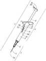
도 1은, 약제를 흡인하기 전 및 약제를 투여한 후의 실시형태의 주사기 전체의 사시도이다.
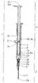
도 2는 도 1에 도시한 주사기의 종절단 측면도이다.
도 3은 도 1에 도시한 주사기의 분해 사시도이다.
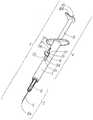
도 4는 도 1에 도시한 주사기 전체의, 약제의 흡인을 완료한 후에 얻은 사시도이다.
도 5는 도 1에 도시한 주사기 전체의, 거품 제거 완료 후에 얻은 사시도이다.
도 6은 도 1에 도시한 주사기 전체의, 투여 전에 얻은 사시도이다.
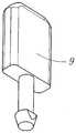
도 7은 슬라이더의 변형예의 사시도이다.
도 8은 슬라이더의 다른 변형예의 사시도이다.
도 9는 슬라이더의 또 다른 변형예의 사시도이다.
도 10은 변형예의 주사기의 절단 측면도이다.
도 11은 다른 변형예의 주사기의 정면도이다.
도 12는 주사기에 부착되는 어댑터의 사시도이다.
도 13은 도 12에 도시한 어댑터를 구비한 주사기의 절단 측면도이다.BRIEF DESCRIPTION OF THE DRAWINGS The perspective view of the whole syringe of embodiment before aspirating a medicine and after administering a medicine.
FIG. 2 is a longitudinal cutaway side view of the syringe shown in FIG. 1. FIG.
3 is an exploded perspective view of the syringe shown in FIG. 1.
Fig. 4 is a perspective view of the entire syringe shown in Fig. 1 obtained after the aspiration of the medicine is completed.
FIG. 5 is a perspective view of the entire syringe shown in FIG. 1 obtained after foam removal is completed. FIG.
FIG. 6 is a perspective view obtained before administration of the entire syringe shown in FIG. 1. FIG.
7 is a perspective view of a modification of the slider.
8 is a perspective view of another modification of the slider.
9 is a perspective view of another modification of the slider.
10 is a cutaway side view of a syringe of a variation.
11 is a front view of a syringe of another variant.
12 is a perspective view of an adapter attached to a syringe.
FIG. 13 is a cutaway side view of the syringe with an adapter shown in FIG. 12; FIG.
이제, 본 발명의 정량 토출 용기를 주사기(1)에 적용한 실시형태를, 도 1 ∼ 도 6을 참조하여 설명한다.An embodiment in which the metered-discharge container of the present invention is applied to the
본 실시형태의 주사기(1)는 주사 바늘 세트(2), 주사기 외통(3) 및 피스톤 세트(4)로 구성된다. 주사 바늘 세트(2)는 주사기 외통(3)의 전방 부분과 나사 결합되어 있다. 주사 바늘 세트(2)에서, 바늘(5)은 바늘 토대부(6)에 압입 고정되어 있다. 바늘 토대부(6)의 내경부(6a) 및 주사기 외통(3)의 립(3a)은 함께 압입 고정되어 있어, 약액이 주사 바늘의 선단 이외에 임의의 다른 위치로부터 누출되는 것을 방지한다. 바늘(5)은 스테인리스강으로 형성되고, 바늘 토대부(6)는 PP(폴리프로필렌)으로 형성된다.The
주사기 외통(3)은, 길이 방향으로 연장되는 실질적으로 관형인 부재이다. 피스톤 세트(4)는, 주사기 외통(3)의 내경부(3b)에, 주사기 외통(3)의 길이 방향으로 이동 가능하도록 삽입되어 있다. 액실은 주사기 외통(3)과 피스톤 세트(4)의 플런저(7)의 선단 사이에 형성되어 있다. 액실의 용량은, 피스톤 세트(4)를 주사기 외통(3)에 대하여 이동시킴으로써 변경할 수 있다.The
플런저(7)의 외경 볼록부(7a)는, 주사기 외통(3)의 내경부(3b)에 슬라이딩 가능한 방식으로 압입되어 있다. 플런저(7)는, 연질 부재인 부틸 고무로 형성되며, 압축 및 변형 가능하다. 이는, 약액이 플런저(7)와 주사기 외통(3)의 내경부(3b)의 간극으로부터 누출되는 것을 방지한다. 더욱 고도로 슬라이딩성(slidability)을 향상시키기 위해서, 플런저(7)의 외주면에 실리콘을 도포한다. 주사기 외통(3)은 PP(폴리프로필렌)로 형성된다.The outer diameter
이제, 피스톤 세트(4)의 구성을 설명한다. 피스톤(8)의 전방에 위치하는 플런저(7)는, 플런저(7)의 내경 오목부(7b)와 피스톤(8)의 전단 볼록부(8a)가 주사기 외통(3)의 길이 방향에 대하여 회전 가능하도록, 피스톤(8)에 고정된다.The configuration of the
슬라이더(9)는, 주사기 외통(3)의 길이 방향에 대하여 수직 방향으로 형성된 피스톤(8)의 삽입공(8b)에 압입되어 있다. 피스톤(8)은 PP(폴리프로필렌)으로 형성되고, 슬라이더(9)는 PP(폴리프로필렌)으로 형성된다.The
슬라이더(9)는, 피스톤 세트(4)를 주사기 외통(3)에 대하여 이동시킴으로써, 주사기 외통(3)의 가이드(3c)를 따라 주사기 외통(3)의 길이 방향에 대하여 이동 가능하게 구성된다. 슬라이더(9)는 주사기 외통(3)의 둘레 방향으로도 이동 가능하게 구성된다.The
이제, 주사기(1)의 조작 방법을 설명한다. 주사기(1)의 조작에는 3가지 조작; 즉, 흡인, 거품 제거 및 투여가 있다.Now, the operation method of the
사용전에 달성되는 주사기(1)의 상태; 즉, 주사기(1)가 바이알로부터 약액을 흡인하기 전에 얻어지는 상태에서는, 슬라이더(9)가 도 1에 도시된 바와 같이 제1 홈(3d)의 전단면(3e)과 접촉하고 있다. 즉, 피스톤 세트(4)가 최전단에 위치한다.The condition of the
다음에, 바이알로부터 약액을 흡인하기 위해, 주사기 외통(3)에 대하여 피스톤 세트(4)를 후방으로 당기면, 슬라이더(9)가 경사면(3f)과 접촉하게 된다. 이어서, 슬라이더(9)가 경사면(3f)을 따라 회전하면서 제2 홈(3g)으로 이동한다. 더욱 피스톤 세트(4)를 후방으로 계속 당기면, 슬라이더(9)가 도 4에 도시된 바와 같이 제2 홈(3g)의 후단면(3h)에 접촉하여, 피스톤 세트(4)가 이동 가능한 범위의 최후단에 위치한다. 이 때, 슬라이더(9)는, 약하게 압입된 상태로 유지되면서, 가이드(3c)의 내부로 돌출된 립(3i)에 의해 가이드 부재(3c)에 고정된다. 이 상태에서 흡인이 완료된 후, 액실의 내부는 약액으로 채워지게 된다.Next, in order to suck the chemical liquid from the vial, when the piston set 4 is pulled backward with respect to the
슬라이더(9)가 가이드(3c)의 후단면(3h)과 접촉하고 있으므로, 피스톤 세트(4)는 더 이상 후방으로 이동하지 않는다. 구체적으로, 피스톤 세트(4)는 주사기 외통(3)의 후방으로 빠져나올 걱정이 없다.Since the
또한, 이 상태에서 주사 바늘 세트(2)를 제거하고, 대신에 캡을 제공하며, 멸균하고, 포장하면, 이 주사기를 예비 충전(pre-filled) 주사기로서 이용할 수 있다.It is also possible to use this syringe as a pre-filled syringe if the needle set 2 is removed in this state, and instead a cap is provided, sterilized and packaged.
이후, 액실 내의 약액으로부터 거품을 제거하는 조작을 행한다. 피스톤(8)의 후단면(8c)을 눌러 피스톤 세트(4)를 전방으로 이동시키면, 슬라이더(9)가 전방으로 이동하여, 액실의 용량이 감소한다. 따라서, 약액이 바늘(5)의 선단공(5a)으로부터 토출된다. 추가로 피스톤 세트(4)를 전방으로 이동시키는 것을 계속하면, 슬라이더(9)가 도 5에 도시된 바와 같이 가이드(3c)의 단부(段部)(목표 위치 접촉부)(3j)와 접촉하여, 피스톤 세트(4)가 더 이상 전진하지 못한다. 이 상태에서, 액실 내의 거품의 제거가 완료되며, 주사기 외통(3)과 주사 바늘 세트(2)의 내부 사이에 형성된 액실은 공기가 없는 상태가 된다.Thereafter, an operation of removing bubbles from the chemical liquid in the liquid chamber is performed. When the piston set 4 is moved forward by pushing the
이제, 투여 조작을 실시한다. 우선, 피스톤(8)의 볼록부(8d)를 주사기 외통(3)의 원주 방향으로 회전시킨다. 이로써 피스톤(8)이 회전하여, 슬라이더(9)가 제2 홈(3g)에서 제1 홈(3d)으로 이동함으로써, 피스톤 세트(4)가 길이 방향을 따라 이동할 수 있게 된다. 피스톤(8)의 후단면(8c)을 추가로 누르면, 슬라이더(9)가 제1 홈(3d)을 따라 전진하여, 슬라이더(9)가 도 1에 도시된 바와 같이 제1 홈(3d)의 전단면(3e)과 접촉한다. 이로써, 피스톤 세트(4)가 최전단에 위치하여, 투여가 완료된다. 따라서, 주사기(1)는 그의 사용 전에 달성되는 것과 동일한 상태에 진입한다.The administration operation is now performed. First, the
또한, 단부(3j)는, 액실의 용량이 투여에 필요한 용량인 목표 용량과 동등해질 때에 슬라이더(9)가 이 단부(3j)와 접촉하는 위치에 배치된다. 구체적으로, 슬라이더(9)가 단부(3j)에서 전단면(3e)까지 이동하도록 피스톤 세트(4)를 전방으로 이동시키면, 목표 용량의 약액이 토출된다.In addition, the
상기와 같이, 본 실시형태의 주사기(1)에서, 단부(3j)는, 액실의 용량이 투여에 필요한 용량인 목표 용량과 동등해질 때에 슬라이더(9)가 이 단부에 접촉하는 위치에 배치된다. 이 이유로, 사용자가, 슬라이더(9)가 단부(3j)에 접촉할 때까지 피스톤(8)의 후단면(8c)을 누르면, 액실 내의 약액의 용량을 목표 용량으로 설정할 수 있다. 이 조작 도중에는, 사용자가, 특히 눈금 등을 보며 주의를 기울일 필요가 없으므로, 간단한 조작으로 액실의 용량을 목표 용량으로 설정할 수 있다. 또한, 이 조작은 숙련을 요하지 않는다. 어떤 사용자라도, 주사기(1)를 취급하여, 항상 액실의 용량을 목표 용량으로 설정할 수 있다.As mentioned above, in the
본 실시형태의 주사기(1)에서는, 후단면(3h)과 가이드(3c)의 단부(3j)의 간격은 항상 일정하게 유지된다. 구체적으로, 용액의 흡인이 완료되는 위치에서 거품의 제거가 완료되는 위치까지 슬라이더(9)가 이동하는 범위는 일정하므로, 거품을 제거하는 조작 도중에 토출되는 약액의 양도 항상 일정하다. 따라서, 후단면(3h)과 단부(3j)의 간격을 적절히 설정함으로써, 약액을 적정한 양으로 일정하게 사용할 수 있다. 종래에는, 거품 제거를 확실히 하기 위해, 과잉량의 약액을 폐기하였으며, 약액이 낭비되었다. 그러나, 본 실시형태의 주사기(1)는, 약액의 낭비적인 사용을 방지한다.In the
이상, 본 발명을 그 실시형태를 이용하여 설명하였으나, 본 발명의 기술적 범위는, 상기 실시형태에 의해 규정된 범위로 한정되지 않는다. 상기 실시형태에는 다양한 변경 또는 개량이 허용될 수 있음이 당업자에게 분명하다.As mentioned above, although this invention was demonstrated using the embodiment, the technical scope of this invention is not limited to the range prescribed | regulated by the said embodiment. It will be apparent to those skilled in the art that various modifications or improvements can be made in the above embodiments.
예를 들어, 첫 번째 실시형태에서는, 주사 바늘 세트(2)의 고정 방법은 나사-결합이며, 주사기 외통(3)의 관 말단은 나사 형상을 가진다. 그러나, 주사 바늘 세트(2)는 일반 주사기의 경우에서와 같이, 루어 주사기법(즉, 차입법)으로 고정할 수도 있다. 또한, 주사기 외통(3)은 PP(폴리프로필렌), PE(폴리에틸렌) 및 PET(폴리에틸렌 테레프탈레이트)와 같은 수지 재질, 또는 스테인리스강 또는 유리로 이루어진 경질의 재질로 형성될 수도 있다.For example, in the first embodiment, the fixing method of the injection needle set 2 is screw-engaged, and the tube end of the
또한, 상기 실시형태에서는, 슬라이더(9)가 직사각형의 형상을 가지나, 슬라이더는 상기 형상으로 한정되지 않는다. 슬라이더(9)는, 예를 들어, 정사각형, 원형, 타원형 또는 표단형(gourd shape)을 취할 수도 있다. 따라서, 슬라이더(9)의 형상은 필요에 따라 선택 가능하다.Moreover, in the said embodiment, although the
또한, 상기 실시형태에서는, 주사기 외통(3), 바늘 토대부(6) 및 피스톤(8)을 투명 수지로 성형하고, 플런저(7) 및 슬라이더(9)를 불투명한 착색 수지로 성형한다. 그러나, 주사기 외통(3), 바늘 토대부(6) 및 피스톤(8)을 불투명한 착색 수지로 성형할 수도 있고, 플런저(7) 및 슬라이더(9)를 투명 수지로 성형할 수도 있다. 또한, 불투명 수지 또는 투명 수지를 양쪽에 사용할 수도 있고, 또는 반투명 수지를 사용할 수 있다. 또한, 이들의 조합도 필요에 따라 선택 가능하다.Moreover, in the said embodiment, the syringe
전술의 실시형태에서, 주사기 외통(3), 바늘 토대부(6), 피스톤(8) 및 슬라이더(9)는 재질로 PP(폴리프로필렌)을 채용하고 있으나, PE(폴리에틸렌) 등을 사용할 수도 있다. 또한, 플런저(7)는 부틸 고무를 사용하고 있으나, 부타디엔 고무, 실리콘 고무, 엘라스토머 수지가 사용될 수도 있다. 따라서, 플런저(7)의 재질은 플런저가 사용되는 상황에 따라 적절하게 선택할 수 있다.In the above embodiment, the
이제, 슬라이더(9)의 형상의 다양한 변형예를, 도 7 ∼ 도 10을 참조하여 설명한다. 본 실시형태에서, 슬라이더(9)는, 이 슬라이더(9)가 피스톤(8)으로부터 빠져 나오지 않도록 피스톤(8)에 압입되는 형상을 갖는다. 그러나, 슬라이더(9)의 형상은 이 형상에 한정되지 않는다. 슬라이더(9)는 다른 형상; 예를 들어, 도 7에 도시된 바와 같이 회전 정지부(rotation stop)를 갖는 화살 형상; 도 8에 도시된 바와 같이, 회전 정지부를 갖는 화살 형상 및 슬릿을 포함하는 형상; 도 9에 도시된 바와 같이, 회전 정지부를 갖는 화살 형상과 C형 고리의 조합인 형상; 및 도 10에 도시된 바와 같이, 슬라이더(9)가 피스톤(8)과 일체화된 형상을 가질 수도 있다.Now, various modifications of the shape of the
각 형상의 특징은 다음과 같다. 도 7에 도시된 회전 정지부를 갖는 화살 형상은, 이 화살 형상에 의해 피스톤(8)으로부터 슬라이더(9)가 빠져나오는 것을 방지하도록 구성된다. 회전 정지부를 갖는 화살 형상 및 슬릿을 포함하는, 도 8에 도시된 형상은 도 7에 도시된 형상에 슬릿을 첨가하여 구성한다. 슬릿에 의해, 주사기(1)의 조립시에 슬라이더(9)의 선단이 변형되어, 삽입공(8b)에 피스톤(8)을 삽입하는 것이 용이하게 된다.The characteristics of each shape are as follows. The arrow shape having the rotation stop shown in FIG. 7 is configured to prevent the
마찬가지로, 회전 정지부를 갖는 화살 형상과 C형 고리의 조합인, 도 9에 도시된 형상에서도, C형 고리에 의해, 조립시에 슬라이더(9)의 선단이 변형되어, 삽입공(8b)에 피스톤(8)을 삽입하는 것이 용이하게 된다.Similarly, also in the shape shown in FIG. 9, which is a combination of an arrow shape having a rotation stop and a C ring, the tip of the
슬라이더(9)와 피스톤(8)을 함께 일체화한 도 10에 도시된 형상은, 슬라이더(9)와 피스톤(8)이 일체화된 단일 부품에 해당한다. 노치(notch)는 슬라이더(9)의 외주면 둘레의 돌출 부분 이면에 형성되며, 이 노치에 의해 형성된 공간 내에서, 슬라이더(9)가 탄성 변형 가능하게 된다. 피스톤 세트(4)를 주사기 외통(3)의 후방으로부터 삽입할 때, 피스톤(8)의 슬라이더(9)가 탄성 변형하면서 피스톤 세트(4)가 삽입되므로, 조립이 용이하게 된다.The shape shown in FIG. 10 in which the
또한, 상기 실시형태에 대해서는, 가이드(3c)가 제1 홈(3d) 및 제2 홈(3g)을 포함하는 예를 들어 설명하였다. 그러나, 가이드(3c)는 3단계 및 4단계와 같은 다단계로 할 수 있다. 또한, 가이드(3c)의 형상도 직선형이 아니라, 원호 형상 또는 스플라인 곡선일 수 있다. 이제, 가이드(3c)의 형상을 도 11을 참조하여 구체적으로 설명한다.In addition, about the said embodiment, the
도 11은, 본 발명의 변형예의 주사기(1)의 정면도이다. 이 변형예에서, 가이드(3c)는 제1 홈(3d), 제2 홈(3g) 및 제3 홈(3l)을 갖는다. 이 3가지 홈(3d, 3g 및 3l)은, 인접한 홈이 각각 상이한 축선을 갖도록 형성된다. 또한, 서로 인접한 제1 홈(3d)과 제2 홈(3g)은 제1 연접부(3n)에서 접속되며, 서로 인접한 제1 홈(3d)과 제3 홈(3l)은 제2 연접부(3o)에서 접속된다.11 is a front view of a
제1 연접부(3n) 및 제2 연접부(3o)는, 주사기 외통(3)의 둘레 방향을 따라 연장되는 공간으로 형성되어 있다. 또한, 제1 연접부(3n) 및 제2 연접부(3o)를 형성하는 벽의 일부가 제1 단부(3j) 및 제2 단부(3e)로서 형성되어 있다.The
제1 단부(3j)는, 슬라이더(9)가 제2 홈(3g)의 내부를 이동하는 동안, 액실의 용량이 제1 목표 용량과 동등해지는 때에 슬라이더(9)가 이 단부(3j)에 접촉하는 위치에 배치된다. 제2 단부(3e)는, 슬라이더(9)가 제1 홈(3d)의 내부를 이동하는 동안, 액실의 용량이 제2 목표 용량과 동등해지는 때에 슬라이더(9)가 이 단부(3e)에 접촉하는 위치에 배치된다. 또한, 전단면(3m)은, 슬라이더(9)가 제3 홈(3l)의 내부를 이동하는 동안, 액실의 용량이 제3 목표 용량과 동등해지는 때에 슬라이더(9)가 이 전단면에 접촉하는 위치에 배치된다.The
슬라이더(9)가 후단면(3h)으로부터, 제1 단부(3j)에 접촉할 때까지 제2 홈(3g)의 내부를 이동하도록, 피스톤(8)을 이동시킴으로써, 제1 목표 용량으로 약액을 토출시킬 수 있다. 또한, 슬라이더(9)가 제1 단부(3j)로부터 원주 방향으로 제1 홈(3d)의 내부를 이동하도록 피스톤(8)을 회전시키고 길이 방향으로 이동시키면, 제2 목표 용량으로 약액을 토출시킬 수 있다. 마찬가지로, 슬라이더(9)가 제2 단부(3e)로부터 원주 방향으로 제3 홈(3l)의 내부를 이동하도록 피스톤(8)을 이동시킴으로써, 제3 목표 용량으로 약액을 토출시킬 수 있다.By moving the
본 변형예의 주사기(1)에서, 슬라이더(9)를, 제1 홈(3d), 제2 홈(3g) 및 제3 홈(3l) 각각의 내부를 통해 이동시킬 때에는, 피스톤(8)을 길이 방향으로 이동시킨다. 한편, 슬라이더(9)를 제2 홈(3g)에서 제1 홈(3d)으로 이동시킬 때에는, 슬라이더(9)가 제1 연접부(3n)를 통과하도록 하기 위해, 피스톤(8)을 원주 방향으로 회전시켜야 한다. 상기와 같이, 슬라이더(9)가 제2 홈(3g)에서 제1 홈(3d)으로 이동하도록 하기 위해서는, 피스톤(8)의 이동 방향이 변경되어야 한다. 상기 구성에 의해, 슬라이더(9)가 제2 홈(3g)에서 제1 홈(3d)으로 연속적으로 이동하지 않으므로, 제1 목표 용량의 약액 및 제2 목표 용량의 약액을, 확실하게 서로 구별하면서 토출시킬 수 있다.In the
이러한 구성에 의하면, 다단계 토출 조작시에, 각 단계에서 정확하게 소정량의 약액을 토출시키는 것이 가능해진다. 각 단계는, 특정 목표에 개별적으로 이용될 수 있다. 예를 들면, 제1 목표 용량은 유아에게 사용할 수 있고; 제1 목표 용량과 제2 목표 용량을 포함하는 합계량은 12세 이하의 아이에게 사용할 수 있으며; 제1 목표 용량, 제2 목표 용량 및 제3 목표 용량을 포함하는 합계 량은 성인에게 사용할 수 있다. 이로써, 하나의 주사기(1)로, 어떠한 연령의 사람 또는 어떠한 체격의 사람에게도 정확한 양의 약제를 투여할 수 있다. 또한, 제1 목표 용량, 제2 목표 용량 및 제3 목표 용량은 동등한 용량, 또는 각각 상이한 용량으로 설정할 수 있다.According to this structure, it becomes possible to discharge a predetermined amount of chemical liquid accurately in each step at the time of a multistage discharge operation. Each step can be used individually for a particular goal. For example, the first target dose may be used for an infant; The total amount comprising the first target dose and the second target dose may be used for a child 12 years of age or younger; The total amount including the first target dose, the second target dose, and the third target dose may be used by an adult. Thus, one
가이드(3c)의 각 홈(3d, 3g 및 3l)은, 직선형이 아닌, 원호 형상 또는 스플라인 곡선을 가질 수 있다. 사람이 사물을 누를 때에는, 사람의 손가락 및 손목과 같은 많은 관절을 사용하면서 누르는 동작을 행한다. 이 때문에, 누르는 동작의 궤적은 일직선이 아니며, 누르기는 약간 만곡된 상태로 행하게 된다. 인간의 동작의 궤적에 맞춰, 가이드(3c)의 형상을 원호 형상 또는 스플라인 곡선으로 함으로써, 주사기(1)의 조작성이 향상된다.Each
또한, 상기 실시형태는, 슬라이더(9)가 주사기 외통(3)의 외측에 돌출하는 예를 들어 설명하였다. 그러나, 슬라이더(9)를 주사기 외통(3) 내에 수용할 수도 있다. 이 경우에는, 피스톤(8)에 가이드를 제공하고; 주사기 외통(3)의 내경부에 피스톤(8) 측으로 돌출하는 볼록부를 제공하며; 이 볼록부에 피스톤 측의 가이드를 맞추는 구조가 채용된다. 이 구조에 의해, 슬라이더가 외부로 드러나지 않기 때문에, 주사기의 외관이 개선된다.In addition, the said embodiment demonstrated the example to which the
또한, 상기 실시형태는, 주사기 외통(3)에 가이드(3c)를 제공하고, 피스톤(8)에 슬라이더(9)를 부착하는 예를 들어 설명하였다. 그러나, 본 발명은 이 실시형태에 한정되지 않는다. 주사기 외통(3)에 슬라이더를 제공할 수도 있고, 피스톤(8)에 가이드를 제공할 수도 있다.In addition, the said embodiment demonstrated the example which provides the
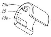
이제, 주사기(1)에 부착하여 사용할 수 있고 토출량을 변경하도록 구성되는 어댑터(10)를, 도 12 및 도 13을 참조하여 설명한다. 도 12는 주사기에 부착하는 어댑터의 사시도이다. 도 13은, 도 12에 도시된 어댑터를 구비한 주사기의 절단 측면 단면도이다.Now, an
어댑터(10)는 주사기 외통(3)의 외주에 착탈 가능하게 부착되는 부재이다. 어댑터(10)의 내주 측에 구비된 볼록부(10a)를 주사기 외통(3)의 제1 홈(3d)에 맞춤으로써, 전단면(3e)에 접촉시킨다. 립(10b)은 어댑터(10)의 내주 측에 제공된다. 주사기 외통(3)이 립(10b)에 의해 걸리는 결과, 어댑터(10)는 주사기 외통(3)의 외주면에 약하게 압입된 채로 움직이지 않게 고정된다.The
어댑터(10)의 볼록부(10a)는, 슬라이더(9)가 전단면(3e)의 앞쪽 위치에서 더 이상 전진하는 것을 방지한다. 어댑터(10)를 부착하는 간단한 수법으로, 목표 용량을 적은 값으로 설정할 수 있다. 또한, 어댑터(10)의 크기를 변경함으로써, 목표 용량을 용이하게 변경할 수 있다.The
어댑터와 주사기를 함께 나사 결합시키고, 그 길이 방향으로 이동 가능하게 함으로써, 어댑터를 임의의 위치에 고정시킬 수 있다. 이렇게 하여, 다양한 용액을 소정량으로 토출할 수 있는 용기가 얻어진다.The adapter can be secured in any position by screwing the adapter and syringe together and allowing their movement in the longitudinal direction. In this way, a container capable of discharging various solutions in a predetermined amount is obtained.
본 실시형태에서는, 주사 바늘을 갖는 주사기를 예로 들어 본 발명을 설명하였다. 그러나, 본 발명은 이 실시형태로 한정되지 않는다. 본 발명의 정량 토출 용기는, 소정 목표 용량의 용액을 흡인 및 토출할 수 있는 용기이다. 따라서, 이 정량 토출 용기는, 유아용 음용약의 투여용 용기, 화장품 아로마 오일을 흡인 및 토출하는 용기, 향수를 유리병에 다시 채우거나 향수를 개인적으로 블렌딩하는 데에 이용하는 용기, 또는 작은 동물을 수유하거나 작은 동물에게 물을 제공할 때에 이용하는 용기로서 사용할 수 있다.In the present embodiment, the present invention has been described by taking a syringe having an injection needle as an example. However, the present invention is not limited to this embodiment. The fixed-quantity discharge container of the present invention is a container capable of sucking and discharging a solution having a predetermined target capacity. Thus, this metered dispense container can be used for the administration of baby drinking medication, containers for sucking and dispensing cosmetic aroma oils, containers for refilling perfumes into glass bottles or for personally blending perfumes, or for feeding small animals. Can be used as a container for use when providing water to small animals.
또한, 가이드를 3단계 및 4단계와 같은 다단계로 하면, 이 주사기는, 제2 단계까지는 시약 1 밀리리터, 제3 단계까지는 시약 2 밀리리터를 적하하는 것과 같이, 페트리 접시에 소정량의 시약을 적하하는 실험의 조건을 변경하는 경우에 유용하게 된다.In addition, when the guide is made into a multi-step such as
가이드(3c)는 주사기 외통(3)을 그 반경 방향으로 관통하는 관통공으로서 형성하고; 슬라이더(9)의 형상을 도 7 ∼ 도 10에 도시된 바와 같이 설정하며; 슬라이더(9)를 피스톤(8)에 착탈 가능하게 부착한다. 이로써 정량 토출 용기의 조립이 용이하게 된다. 또한, 정량 토출 용기의 분해도 용이하므로, 용기를 분해하고, 부품을 세정하고, 부품을 재조립함으로써, 정량 토출 용기를 재사용할 수 있다.The
본 발명을 특정한 예시적 실시형태를 참조하여 상세히 설명하였으나, 본 발명의 개념 및 범위를 벗어나지 않고 여러가지 변경 또는 수정이 이뤄질 수 있음이 당업자에게 분명하다.While the invention has been described in detail with reference to specific exemplary embodiments, it will be apparent to those skilled in the art that various changes or modifications can be made therein without departing from the spirit and scope of the invention.
본 출원은, 2011년 4월 25일에 출원된 일본 특허 출원 제2011-098003호를 기초로 하며, 그 내용이 본원에 참조로서 인용되어 있다.This application is based on the JP Patent application 2011-098003 of an application on April 25, 2011, The content is taken in here as a reference.
본 발명의 정량 토출 용기에 의하면, 사용자는, 액체로 채워진 액실의 용량이 목표 용량과 동등해지는 시점을, 슬라이더가 목표 위치 접촉부와 접촉하는 것으로부터 확인할 수 있다. 따라서, 본 발명은, 항상 목표 용량으로 액체를 용이하고 정확하게 토출할 수 있는 정량 토출 용기를 제공할 수 있다.According to the fixed-quantity discharge container of the present invention, the user can confirm the time point at which the capacity of the liquid chamber filled with the liquid is equal to the target capacity from the contact of the slider with the target position contact portion. Therefore, the present invention can provide a fixed-quantity discharge container capable of always and easily discharging liquid at a target capacity.
Claims (4)
Translated fromKorean상기 주사기 외통에 길이 방향으로 이동 가능하게 삽입되어, 이 주사기 외통과의 사이에 액실을 형성하는 피스톤
을 포함하는 정량 토출 용기로서,
상기 주사기 외통 및 피스톤 중 하나는, 길이 방향으로 연장되는 가이드를 포함하고;
상기 주사기 외통 및 피스톤 중 다른 하나는, 이 주사기 외통 및 피스톤 중 다른 하나와 함께 상기 가이드 내에서 이동 가능한 슬라이더를 포함하며;
상기 가이드에는, 상기 액실의 용량이 목표 용량과 동등할 때에 상기 슬라이더가 접촉하는 목표 위치 접촉부가 구비되어 있는 정량 토출 용기.Syringe barrels; And
A piston which is inserted in the syringe barrel so as to be movable in the longitudinal direction and forms a liquid chamber between the syringe barrel and the syringe barrel.
As a metered discharge container comprising a,
One of the syringe barrel and the piston includes a guide extending in the longitudinal direction;
The other of the syringe barrel and piston includes a slider movable within the guide with the other of the syringe barrel and piston;
The said guide has a fixed-quantity discharge container provided with the target position contact part which the said slider contacts when the capacity | capacitance of the said liquid chamber is equal to a target capacity | capacitance.
서로 인접한 상기 홈은 이 홈의 축선이 서로 상이하도록 형성되며;
서로 인접한 상기 홈은 연접부에서 접속되고;
원주 방향으로 연장하는 상기 연접부의 벽이 상기 목표 위치 접촉부로서 기능하는 정량 토출 용기.The device of claim 1, wherein the guide comprises a plurality of grooves;
The grooves adjacent to each other are formed such that the axes of the grooves are different from each other;
The grooves adjacent to each other are connected at a junction;
A fixed-quantity discharge container in which a wall of the junction portion extending in the circumferential direction functions as the target position contact portion.
상기 슬라이더는 상기 주사기 외통의 외측으로부터 상기 피스톤에 착탈 가능하게 부착되는 정량 토출 용기.3. The syringe barrel according to claim 1 or 2, wherein the guide is formed in the syringe barrel as a through hole radially penetrating the syringe barrel;
And the slider is detachably attached to the piston from the outside of the syringe barrel.
Applications Claiming Priority (3)
| Application Number | Priority Date | Filing Date | Title |
|---|---|---|---|
| JPJP-P-2011-098003 | 2011-04-26 | ||
| JP2011098003 | 2011-04-26 | ||
| PCT/JP2012/061236WO2012147862A1 (en) | 2011-04-26 | 2012-04-26 | Fixed amount discharge container |
Publications (1)
| Publication Number | Publication Date |
|---|---|
| KR20140015495Atrue KR20140015495A (en) | 2014-02-06 |
Family
ID=47072377
Family Applications (1)
| Application Number | Title | Priority Date | Filing Date |
|---|---|---|---|
| KR1020137028002ACeasedKR20140015495A (en) | 2011-04-26 | 2012-04-26 | Fixed amount discharge container |
Country Status (16)
| Country | Link |
|---|---|
| US (1) | US9669988B2 (en) |
| EP (1) | EP2703023A4 (en) |
| JP (2) | JPWO2012147862A1 (en) |
| KR (1) | KR20140015495A (en) |
| CN (1) | CN103596611A (en) |
| AU (2) | AU2012248256A1 (en) |
| BR (1) | BR112013027578A2 (en) |
| CA (1) | CA2833861A1 (en) |
| CL (1) | CL2013003095A1 (en) |
| CO (1) | CO6870014A2 (en) |
| EA (1) | EA201391576A1 (en) |
| MX (1) | MX2013012370A (en) |
| PE (1) | PE20141784A1 (en) |
| PH (1) | PH12013502188A1 (en) |
| SG (2) | SG194595A1 (en) |
| WO (1) | WO2012147862A1 (en) |
Cited By (1)
| Publication number | Priority date | Publication date | Assignee | Title |
|---|---|---|---|---|
| KR101868317B1 (en)* | 2018-05-04 | 2018-06-15 | 정의택 | Quantitative repetitive syringe and method for setting injection quantity of medication |
Families Citing this family (18)
| Publication number | Priority date | Publication date | Assignee | Title |
|---|---|---|---|---|
| US9320647B2 (en) | 2010-03-31 | 2016-04-26 | Ocuject, Llc | Device and method for intraocular drug delivery |
| US9408746B2 (en) | 2010-03-31 | 2016-08-09 | Ocuject, Llc | Device and method for intraocular drug delivery |
| US9504603B2 (en) | 2012-04-02 | 2016-11-29 | Ocuject, Llc | Intraocular delivery devices and methods therefor |
| US9421129B2 (en)* | 2012-04-02 | 2016-08-23 | Ocuject, Llc | Intraocular delivery devices and methods therefor |
| CN109171766A (en) | 2012-11-30 | 2019-01-11 | 木兰医药技术股份有限公司 | Body fluid barrier means and the method for completely cutting off body fluid using body fluid barrier means |
| US9340346B2 (en)* | 2013-11-21 | 2016-05-17 | Smarthealth, Inc. | Precision dispensing device of small volume from pre-filled syringes |
| JP6242682B2 (en)* | 2013-12-27 | 2017-12-06 | 株式会社吉野工業所 | Syringe type ejection container |
| FR3016304B1 (en)* | 2014-01-13 | 2018-03-09 | Aptar France Sas | FLUID PRODUCT DISPENSING ASSEMBLY AND METHOD OF USING SUCH ASSEMBLY. |
| WO2016091554A1 (en)* | 2014-12-12 | 2016-06-16 | Carebay Europe Ltd | Dose setting mechanism and medicament delivery device comprising the dose setting mechanism |
| JP6406706B2 (en)* | 2015-02-05 | 2018-10-17 | 公立大学法人奈良県立医科大学 | Syringe rotating device |
| WO2016201406A1 (en) | 2015-06-12 | 2016-12-15 | Bullington Gregory J | Devices and methods for syringe-based fluid transfer for bodily-fluid sampling |
| US10653845B2 (en)* | 2016-01-21 | 2020-05-19 | Merit Medical Systems, Inc. | Coverings for syringe plunger tips and methods related thereto |
| WO2018166985A1 (en)* | 2017-03-13 | 2018-09-20 | Sanofi-Aventis Deutschland Gmbh | Drug delivery device |
| US11350945B2 (en) | 2017-11-13 | 2022-06-07 | Merit Medical Systems, Inc. | Staged deflation syringe systems and associated methods |
| CN111491680B (en) | 2017-12-13 | 2023-08-29 | 里珍纳龙药品有限公司 | Device and method for accurate dose delivery |
| WO2020163744A1 (en) | 2019-02-08 | 2020-08-13 | Magnolia Medical Technologies, Inc. | Devices and methods for bodily fluid collection and distribution |
| EP4603120A2 (en) | 2019-06-05 | 2025-08-20 | Regeneron Pharmaceuticals, Inc. | Devices and methods for precision dose delivery |
| EP4400132A1 (en)* | 2023-01-12 | 2024-07-17 | Stephen Terence Dunne | Multi-dose syringe |
Family Cites Families (37)
| Publication number | Priority date | Publication date | Assignee | Title |
|---|---|---|---|---|
| US963051A (en)* | 1910-02-10 | 1910-07-05 | Robert A Kooken | Ointment-applier. |
| FR711644A (en)* | 1930-05-23 | 1931-09-14 | Collin Et Cie Soc | Advanced syringe to perform series of dosed and variable injections |
| US2409656A (en)* | 1945-04-20 | 1946-10-22 | Harold S Austin | Hypodermic syringe |
| US2428577A (en)* | 1945-09-06 | 1947-10-07 | Waddy T Mathis | Liquid-measuring dispenser |
| US2502639A (en)* | 1948-02-16 | 1950-04-04 | American Instr Corp | Hypodermic syringe |
| US2648334A (en)* | 1949-10-28 | 1953-08-11 | Turnbull | Hypodermic injection assembly |
| US2695023A (en)* | 1952-01-04 | 1954-11-23 | Pfizer & Co C | Hypodermic syringe |
| FR1156298A (en)* | 1956-09-06 | 1958-05-14 | Seringues Ind Soc D Expl Des | Syringe for hypodermic injections |
| FR1412547A (en)* | 1964-08-20 | 1965-10-01 | Comptoir De Diffusion De Produ | Injection syringe |
| ES212610Y (en)* | 1975-05-23 | 1976-11-01 | Montero Sanchez | VETERINARY DOSING SYRINGE. |
| DE2711124C2 (en)* | 1977-03-15 | 1979-05-10 | Labora Mannheim Gmbh Fuer Labortechnik, 6800 Mannheim | Hand pipette |
| US4117728A (en)* | 1977-12-22 | 1978-10-03 | Miles Laboratories, Inc. | Pipette |
| US4261205A (en)* | 1979-10-02 | 1981-04-14 | Nichiryo Co., Ltd | Pipetting device |
| US4466426A (en)* | 1981-06-29 | 1984-08-21 | Blackman Seymour N | Syringe with actinic ray blocking stripe |
| US4475905A (en)* | 1982-09-30 | 1984-10-09 | Himmelstrup Anders B | Injection device |
| DK172984D0 (en)* | 1984-03-30 | 1984-03-30 | Novo Industri As | DISPENSER |
| US4610668A (en)* | 1985-10-02 | 1986-09-09 | Fleig John A | Preselected multiple dosage syringe |
| US4832694A (en)* | 1988-02-08 | 1989-05-23 | Raphael Iii Julian J | Programmed action hypodermic syringe |
| DE3810262A1 (en)* | 1988-03-25 | 1989-10-12 | Henning Berlin Gmbh | DEVICE FOR THE DOSED ADMINISTRATION OF A LIQUID MEDICINAL PRODUCT |
| DE4016126A1 (en)* | 1990-04-17 | 1991-10-24 | Coster Tecnologie Speciali Spa | DEVICE FOR TRANSNASAL OR ORAL ADMINISTRATION OF MEDICATIONS OR THE LIKE |
| US5318544A (en)* | 1992-10-20 | 1994-06-07 | Kerr Manufacturing Company | Metering syringe |
| JP3519166B2 (en)* | 1995-03-28 | 2004-04-12 | 株式会社吉野工業所 | Liquid dispensing container |
| AUPO940697A0 (en)* | 1997-09-23 | 1997-10-16 | Kaal, Joseph Hermes | Retractable syringe |
| SE9704769D0 (en)* | 1997-12-19 | 1997-12-19 | Astra Ab | Medical device |
| JP4866498B2 (en) | 2000-04-21 | 2012-02-01 | 武田薬品工業株式会社 | Prefilled syringe |
| US7500967B2 (en)* | 2000-04-26 | 2009-03-10 | Unitract Pty. Ltd. | Single use syringe |
| US6527742B1 (en)* | 2001-11-14 | 2003-03-04 | Robert C. Malenchek | Safety syringe |
| US6926697B2 (en)* | 2003-05-13 | 2005-08-09 | Robert Malenchek | Adaptor for converting a non-safety syringe into a safety syringe |
| US7393345B2 (en)* | 2003-07-18 | 2008-07-01 | Chang-Ming Yang | Sterilized safety syringe |
| WO2006020756A2 (en)* | 2004-08-10 | 2006-02-23 | Allergan, Inc. | Step by step botox injector |
| US20060084919A1 (en) | 2004-10-18 | 2006-04-20 | Shaw Thomas J | Fixed-dose syringe with limited aspiration |
| US20080302932A1 (en)* | 2007-06-08 | 2008-12-11 | Smiths Medical Asd, Inc. | Mounting Clip for Fluid Reservoir |
| US7976510B2 (en)* | 2008-02-28 | 2011-07-12 | Becton, Dickinson And Company | Syringe with adjustable two piece plunger rod |
| RU2496528C2 (en) | 2008-05-02 | 2013-10-27 | Санофи-Авентис Дойчланд Гмбх | Drug feeder |
| US8376993B2 (en)* | 2008-08-05 | 2013-02-19 | Antares Pharma, Inc. | Multiple dosage injector |
| DE102008049082A1 (en) | 2008-09-26 | 2010-04-01 | Henke-Sass, Wolf Gmbh | Syringe, in particular for veterinary applications |
| US8851339B2 (en)* | 2009-02-19 | 2014-10-07 | S.C. Johnson & Son, Inc. | Applicator for self-adhesive products |
- 2012
- 2012-04-26BRBR112013027578Apatent/BR112013027578A2/ennot_activeIP Right Cessation
- 2012-04-26JPJP2013512434Apatent/JPWO2012147862A1/enactivePending
- 2012-04-26EAEA201391576Apatent/EA201391576A1/enunknown
- 2012-04-26MXMX2013012370Apatent/MX2013012370A/enunknown
- 2012-04-26SGSG2013078779Apatent/SG194595A1/enunknown
- 2012-04-26USUS14/114,093patent/US9669988B2/ennot_activeExpired - Fee Related
- 2012-04-26CNCN201280020440.2Apatent/CN103596611A/enactivePending
- 2012-04-26WOPCT/JP2012/061236patent/WO2012147862A1/enactiveApplication Filing
- 2012-04-26EPEP12776550.1Apatent/EP2703023A4/ennot_activeWithdrawn
- 2012-04-26PHPH1/2013/502188Apatent/PH12013502188A1/enunknown
- 2012-04-26CACA2833861Apatent/CA2833861A1/ennot_activeAbandoned
- 2012-04-26PEPE2013002409Apatent/PE20141784A1/ennot_activeApplication Discontinuation
- 2012-04-26SGSG10201603135WApatent/SG10201603135WA/enunknown
- 2012-04-26KRKR1020137028002Apatent/KR20140015495A/ennot_activeCeased
- 2012-04-26AUAU2012248256Apatent/AU2012248256A1/ennot_activeAbandoned
- 2013
- 2013-10-24COCO13252776Apatent/CO6870014A2/enactiveIP Right Grant
- 2013-10-25CLCL2013003095Apatent/CL2013003095A1/enunknown
- 2016
- 2016-11-15AUAU2016259317Apatent/AU2016259317A1/ennot_activeAbandoned
- 2016-11-30JPJP2016232389Apatent/JP2017060837A/enactivePending
Cited By (1)
| Publication number | Priority date | Publication date | Assignee | Title |
|---|---|---|---|---|
| KR101868317B1 (en)* | 2018-05-04 | 2018-06-15 | 정의택 | Quantitative repetitive syringe and method for setting injection quantity of medication |
Also Published As
| Publication number | Publication date |
|---|---|
| WO2012147862A1 (en) | 2012-11-01 |
| US20140124542A1 (en) | 2014-05-08 |
| CN103596611A (en) | 2014-02-19 |
| BR112013027578A2 (en) | 2017-02-14 |
| EP2703023A1 (en) | 2014-03-05 |
| CO6870014A2 (en) | 2014-02-20 |
| AU2016259317A1 (en) | 2016-12-01 |
| MX2013012370A (en) | 2014-02-03 |
| AU2012248256A1 (en) | 2013-11-07 |
| JPWO2012147862A1 (en) | 2014-07-28 |
| PE20141784A1 (en) | 2014-12-07 |
| SG10201603135WA (en) | 2016-05-30 |
| EA201391576A1 (en) | 2014-02-28 |
| SG194595A1 (en) | 2013-12-30 |
| US9669988B2 (en) | 2017-06-06 |
| PH12013502188A1 (en) | 2014-01-06 |
| NZ616879A (en) | 2015-02-27 |
| CA2833861A1 (en) | 2012-11-01 |
| CL2013003095A1 (en) | 2014-06-20 |
| EP2703023A4 (en) | 2014-09-24 |
| JP2017060837A (en) | 2017-03-30 |
Similar Documents
| Publication | Publication Date | Title |
|---|---|---|
| KR20140015495A (en) | Fixed amount discharge container | |
| EP2788054B1 (en) | Accurate dose control mechanisms and drug delivery syringes | |
| US7125394B2 (en) | Applicator for dispensing a medicinal substance | |
| US5496284A (en) | Dual-chamber syringe & method | |
| EP3513826B1 (en) | Plunger assembly including a plunger rod for advancing a stopper through a syringe | |
| EP3171917B1 (en) | Dose divider syringe | |
| US20080132852A1 (en) | Dosage device | |
| JPH04502877A (en) | Portable syringe for delivering multiple types of drugs in liquid or paste form | |
| JP2007159717A (en) | Syringe | |
| JP5861327B2 (en) | Metered discharge container | |
| JP2015228878A (en) | Quantitative discharge container | |
| EP3436109B1 (en) | Plunger slack syringe | |
| HK1190953A (en) | Fixed amount discharge container | |
| HK1190967A (en) | Fixed amount discharge container | |
| NZ616879B2 (en) | Fixed amount discharge container | |
| WO2017072727A1 (en) | Syringe and method of using same | |
| HK1200125B (en) | Accurate dose control mechanisms and drug delivery syringes |
Legal Events
| Date | Code | Title | Description |
|---|---|---|---|
| PA0105 | International application | Patent event date:20131024 Patent event code:PA01051R01D Comment text:International Patent Application | |
| PG1501 | Laying open of application | ||
| PA0201 | Request for examination | Patent event code:PA02012R01D Patent event date:20170313 Comment text:Request for Examination of Application | |
| E902 | Notification of reason for refusal | ||
| PE0902 | Notice of grounds for rejection | Comment text:Notification of reason for refusal Patent event date:20180917 Patent event code:PE09021S01D | |
| E601 | Decision to refuse application | ||
| PE0601 | Decision on rejection of patent | Patent event date:20190102 Comment text:Decision to Refuse Application Patent event code:PE06012S01D Patent event date:20180917 Comment text:Notification of reason for refusal Patent event code:PE06011S01I |