KR20140014492A - Rolling device for lithium ion secondary battery - Google Patents
Rolling device for lithium ion secondary batteryDownload PDFInfo
- Publication number
- KR20140014492A KR20140014492AKR1020120080556AKR20120080556AKR20140014492AKR 20140014492 AKR20140014492 AKR 20140014492AKR 1020120080556 AKR1020120080556 AKR 1020120080556AKR 20120080556 AKR20120080556 AKR 20120080556AKR 20140014492 AKR20140014492 AKR 20140014492A
- Authority
- KR
- South Korea
- Prior art keywords
- winding
- secondary battery
- unit
- core
- main
- Prior art date
- Legal status (The legal status is an assumption and is not a legal conclusion. Google has not performed a legal analysis and makes no representation as to the accuracy of the status listed.)
- Granted
Links
Images


Classifications
- H—ELECTRICITY
- H01—ELECTRIC ELEMENTS
- H01M—PROCESSES OR MEANS, e.g. BATTERIES, FOR THE DIRECT CONVERSION OF CHEMICAL ENERGY INTO ELECTRICAL ENERGY
- H01M10/00—Secondary cells; Manufacture thereof
- H01M10/04—Construction or manufacture in general
- H01M10/0404—Machines for assembling batteries
- H01M10/0409—Machines for assembling batteries for cells with wound electrodes
- H—ELECTRICITY
- H01—ELECTRIC ELEMENTS
- H01M—PROCESSES OR MEANS, e.g. BATTERIES, FOR THE DIRECT CONVERSION OF CHEMICAL ENERGY INTO ELECTRICAL ENERGY
- H01M10/00—Secondary cells; Manufacture thereof
- H01M10/04—Construction or manufacture in general
- H01M10/0431—Cells with wound or folded electrodes
- H—ELECTRICITY
- H01—ELECTRIC ELEMENTS
- H01M—PROCESSES OR MEANS, e.g. BATTERIES, FOR THE DIRECT CONVERSION OF CHEMICAL ENERGY INTO ELECTRICAL ENERGY
- H01M10/00—Secondary cells; Manufacture thereof
- H01M10/05—Accumulators with non-aqueous electrolyte
- H01M10/052—Li-accumulators
- H01M10/0525—Rocking-chair batteries, i.e. batteries with lithium insertion or intercalation in both electrodes; Lithium-ion batteries
- H—ELECTRICITY
- H01—ELECTRIC ELEMENTS
- H01M—PROCESSES OR MEANS, e.g. BATTERIES, FOR THE DIRECT CONVERSION OF CHEMICAL ENERGY INTO ELECTRICAL ENERGY
- H01M10/00—Secondary cells; Manufacture thereof
- H01M10/05—Accumulators with non-aqueous electrolyte
- H01M10/058—Construction or manufacture
- H01M10/0587—Construction or manufacture of accumulators having only wound construction elements, i.e. wound positive electrodes, wound negative electrodes and wound separators
- H—ELECTRICITY
- H01—ELECTRIC ELEMENTS
- H01M—PROCESSES OR MEANS, e.g. BATTERIES, FOR THE DIRECT CONVERSION OF CHEMICAL ENERGY INTO ELECTRICAL ENERGY
- H01M2220/00—Batteries for particular applications
- H01M2220/30—Batteries in portable systems, e.g. mobile phone, laptop
- Y—GENERAL TAGGING OF NEW TECHNOLOGICAL DEVELOPMENTS; GENERAL TAGGING OF CROSS-SECTIONAL TECHNOLOGIES SPANNING OVER SEVERAL SECTIONS OF THE IPC; TECHNICAL SUBJECTS COVERED BY FORMER USPC CROSS-REFERENCE ART COLLECTIONS [XRACs] AND DIGESTS
- Y02—TECHNOLOGIES OR APPLICATIONS FOR MITIGATION OR ADAPTATION AGAINST CLIMATE CHANGE
- Y02E—REDUCTION OF GREENHOUSE GAS [GHG] EMISSIONS, RELATED TO ENERGY GENERATION, TRANSMISSION OR DISTRIBUTION
- Y02E60/00—Enabling technologies; Technologies with a potential or indirect contribution to GHG emissions mitigation
- Y02E60/10—Energy storage using batteries
- Y—GENERAL TAGGING OF NEW TECHNOLOGICAL DEVELOPMENTS; GENERAL TAGGING OF CROSS-SECTIONAL TECHNOLOGIES SPANNING OVER SEVERAL SECTIONS OF THE IPC; TECHNICAL SUBJECTS COVERED BY FORMER USPC CROSS-REFERENCE ART COLLECTIONS [XRACs] AND DIGESTS
- Y02—TECHNOLOGIES OR APPLICATIONS FOR MITIGATION OR ADAPTATION AGAINST CLIMATE CHANGE
- Y02P—CLIMATE CHANGE MITIGATION TECHNOLOGIES IN THE PRODUCTION OR PROCESSING OF GOODS
- Y02P70/00—Climate change mitigation technologies in the production process for final industrial or consumer products
- Y02P70/50—Manufacturing or production processes characterised by the final manufactured product
Landscapes
- Engineering & Computer Science (AREA)
- Chemical & Material Sciences (AREA)
- Manufacturing & Machinery (AREA)
- Chemical Kinetics & Catalysis (AREA)
- Electrochemistry (AREA)
- General Chemical & Material Sciences (AREA)
- Secondary Cells (AREA)
- Materials Engineering (AREA)
Abstract
Translated fromKoreanDescription
Translated fromKorean본 발명은 초고속 와인딩이 가능한 이차전지의 권취장치에 관한 것이다.The present invention relates to a winding device of a secondary battery capable of ultra-fast winding.
최근에는 셀룰라 폰, 노트북 컴퓨터, 캠코더 등의 콤팩트하고 경량화 된 전기/전자 장치들이 활발하게 개발 및 생산되고 있다. 이러한 휴대용 전기/전자장치들은 별도의 전원이 구비되지 않은 장소에서도 작동될 수 있도록Recently, compact and lightweight electric / electronic devices such as cellular phones, notebook computers, camcorders, etc. have been actively developed and produced. These portable electrical / electronic devices can be operated in places where no separate power source is provided.
전지 팩을 내장하고 있다. 내장된 전지 팩은 휴대용 전기/전자 장치를 일정기간 동안 구동시키기 위해 일정 레벨의 전압을 출력시킬 수 있도록 내부에 적어도 하나의 전지를 구비하고 있다.The battery pack is built in. The built-in battery pack includes at least one battery therein for outputting a predetermined level of voltage for driving the portable electric / electronic device for a period of time.
전지 팩은 경제적인 측면을 고려하여 최근에는 충ㆍ방전이 가능한 이차전지를 채용하고 있다. 이차전지에는 대표적으로, 니켈-카드뮴(Ni-Cd) 전지와 니켈-수소(Ni-MH)전지 및 리튬(Li) 전지와 리튬 이온(Li-ion) 전지 등의 리튬 이차 전지 등이 있다.In consideration of economical aspects, battery packs employ secondary batteries that can be charged and discharged in recent years. Representative secondary batteries include lithium secondary batteries such as nickel-cadmium (Ni-Cd) batteries, nickel-hydrogen (Ni-MH) batteries, lithium (Li) batteries, and lithium ion (Li-ion) batteries.
특히, 리튬 이차 전지는 작동 전압이 3.6V~4.3V의 범위에서 통상 구현되며, 휴대용 전자 장비 전원으로 많이 사용되고 있는 니켈-카드뮴 전지나, 니켈-수소 전지보다 3배나 높고, 단위 중량당 에너지 밀도가 높다는 측면에서 급속도로 신장되고 있는 추세이다.In particular, lithium secondary batteries are typically implemented in the operating voltage range of 3.6V to 4.3V, and are three times higher than nickel-cadmium batteries or nickel-hydrogen batteries, which are widely used as power sources for portable electronic equipment, and have high energy density per unit weight. It is rapidly increasing in terms of aspect.
이러한 이차 전지는 주로 양극 활물질로 리튬계 산화물, 음극 활물질로는 탄소재를 사용하고 있다. 일반적으로는, 전해액의 종류에 따라 액체 전해질 전지와, 고분자 전해질 전지로 분류되며, 액체 전해질을 사용하는 전지를 리튬 이온 전지라 하고, 고분자 전해질을 사용하는 전지를 리튬 폴리머 전지라고 한다. 또한, 리튬 이차 전지는 여러 가지 형상으로 제조되고 있는데, 대표적인 형상으로는 원통형과, 각형과, 파우치형을 들 수 있다.Such secondary batteries mainly use lithium-based oxides as positive electrode active materials and carbon materials as negative electrode active materials. Generally, a battery using a liquid electrolyte is referred to as a lithium ion battery, and a battery using a polymer electrolyte is referred to as a lithium polymer battery, which is classified as a liquid electrolyte cell and a polymer electrolyte cell, depending on the type of the electrolyte. In addition, the lithium secondary battery is manufactured in various shapes. Typical shapes include a cylindrical shape, a square shape, and a pouch shape.
통상적으로, 이차 전지는 전극 조립체(젤리롤(jelly roll) 또는 권취품)와, 전극 조립체를 수용하는 리튬 이차전지용 케이스와, 리튬 이차 전지용 케이스 내측에 주입되어 리튬 이온의 이동을 가능하게 하는 전해액 및 케이스를 마감하는 캡 조립체를 포함한다.In general, the secondary battery includes an electrode assembly (jelly roll or wound product), a lithium secondary battery case accommodating the electrode assembly, an electrolyte solution injected into the lithium secondary battery case to allow lithium ions to move, and A cap assembly closing the case.
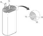
도 1은 이차전지의 구조 중 젤리롤(jelly roll) 타입의 각형 이차전지의 전극조립체를 도시한 개념도이다.FIG. 1 is a conceptual view illustrating an electrode assembly of a jelly roll type square secondary battery among structures of a secondary battery.
도시된 것과 같이, 이차전지의 구조 중 젤리롤(jelly roll) 타입의 각형 이차전지의 전극조립체는 양극집전체의 소정영역에 양극활물질층이 형성된 양극전극판(10), 음극집전체의 소정영역에 음극활물질층이 형성된 음극전극판(20), 상기 양극전극판(10) 및 음극전극판(20)상에 도포되어 상기 양극전극판(10)과 음극전극판(20)의 쇼트(short)를 방지하고 리튬 이온의 이동만 가능하게 하는 세라믹 세퍼레이터 기능막(30,이하 분리막라 한다)이 젤리-롤 형상으로 권취되어 형성된다. 그리고 전극조립체 상부로는 각 전극의 전극리드(15, 25)가 돌출되게 된다.As shown in the drawing, the electrode assembly of the jelly roll type secondary battery of the structure of the secondary battery has a
도 2는 도 1에서 상술한 이차전지의 구조 중 젤리롤(jelly roll) 타입의 각형 이차전지의 전극조립체의 권취장치의 요부를 개념화단 도면이다.FIG. 2 is a conceptual diagram illustrating a main portion of a winding device of an electrode assembly of a jelly roll type square secondary battery of the secondary battery described above with reference to FIG. 1.
젤리롤(jelly roll) 타입의 각형 이차전지의 전극조립체의 권취장치는 회전구동력을 제공하는 구동부(2)와 연결되는 권심부재(1)가 구비되며, 상기 권심부재가 회전하며 상술한 양극, 분리막, 음극의 적층구조물이 권취되게 된다.The winding device of an electrode assembly of a jelly roll type rectangular secondary battery includes a winding
상기 권심부재(1)은 얇고 육각형의 단면 형상으로 단일재질로 형성되며, 전극조립체의 규격에 따라 그에 맞는 새로운 권심부재(1)가 형성되게 된다. 그러나 이러한 종래의 권심부재(1)의 경우 단변부분의 회전 각속도(X2)와 장변 부분의 회전 각속도(X1)의 차이가 커, 전지의 크기가 커지면 권취(winding) 속도가 느려지며, 이를 극복하기 위해 권취속도를 높이는 경우에는 권취되는 전극에 충격이 가해지게 되는 문제가 발생하게 되는 문제가 발생하게 된다.The
본 발명은 상술한 문제를 해결하기 위하여 안출된 것으로, 본 발명의 목적은 젤리롤(jelly roll) 타입의 이차전지의 권취장치의 권심의 구조를 다수의 단위권심으로 이루어지는 구조로 형성하여, 각형 이차전지의 선속도의 상이점으로 인한 와인딩(winding) 속도의 저해문제를 해소하고, 권취시 권취되는 전극에 가해지는 회전에 의한 전극 충격을 최소화하여 신뢰성 높은 이차전지를 제공하는데 있다.The present invention has been made to solve the above-described problems, an object of the present invention is to form a structure of the core of the winding device of the secondary battery of the jelly roll (jelly roll) type to a structure consisting of a plurality of unit cores, square secondary It is to solve the problem of inhibiting the winding speed (winding) due to the difference of the linear speed of the battery, and to provide a secondary battery with high reliability by minimizing the electrode impact due to the rotation applied to the electrode wound during winding.
상술한 과제를 해결하기 위한 수단으로서, 본 발명은 이차전지의 권취장치에 있어서, 축회전을 수행하며 극판을 권취하는 메인권심부; 상기 메인권심부에 일단이 결합되어 외부방향으로 연장되는 커넥팅유닛; 및 상기 지지부재의 타단에 연결되는 다수의 단위권심부;를 포함하는 이차전지의 권취장치를 제공한다.As a means for solving the above problems, the present invention is a winding device of a secondary battery, the main winding portion for winding the pole plate while performing axial rotation; A connecting unit having one end coupled to the main core part and extending outwardly; And a plurality of unit winding parts connected to the other end of the support member.
본 발명에 따르면, 젤리롤(jelly roll) 타입의 이차전지의 권취장치의 권심의 구조를 다수의 단위권심으로 이루어지는 구조로 형성하여, 각형 이차전지의 선속도의 상이점으로 인한 와인딩(winding) 속도의 저해문제를 해소하고, 권취시 권취되는 전극에 가해지는 회전에 의한 전극 충격을 최소화하여 신뢰성 높은 이차전지를 제공할 수 있는 효과가 있다.According to the present invention, the winding structure of the winding device of a jelly roll type secondary battery is formed in a structure consisting of a plurality of unit windings, and thus the winding speed due to the difference in the linear velocity of the square secondary battery There is an effect to solve the problem of inhibition, to minimize the impact of the electrode due to the rotation applied to the electrode wound during winding to provide a reliable secondary battery.
나아가, 원기둥 모양의 단위권심의 배치거리를 조절하여 다양한 사이즈의 전지를 제조할 수 있는 효과도 있다.Furthermore, there is also an effect that can be produced in a battery of various sizes by adjusting the arrangement distance of the cylindrical unit winding.
도 1은 종래의 이차전지의 구조 중 젤리롤(jelly roll) 타입의 각형 이차전지의 전극조립체를 도시한 개념도이다.
도 2는 도 1에서 상술한 이차전지의 구조 중 젤리롤(jelly roll) 타입의 각형 이차전지의 전극조립체의 권취장치의 요부를 개념화단 도면이다.
도 3 및 도 4는 본 발명에 따른 권취장치의 사시도이며, 도 5는 본 발명에 따른 권취장치의 상부 평면도를 도시한 것이다.
도 6은 단위권심의 형상을 도시한 개념도이다.1 is a conceptual diagram illustrating an electrode assembly of a jelly roll type square secondary battery of a conventional secondary battery.
FIG. 2 is a conceptual diagram illustrating a main portion of a winding device of an electrode assembly of a jelly roll type square secondary battery of the secondary battery described above with reference to FIG. 1.
3 and 4 are perspective views of the winding apparatus according to the present invention, Figure 5 shows a top plan view of the winding apparatus according to the present invention.
6 is a conceptual diagram showing the shape of the unit core.
이하에서는 첨부한 도면을 참조하여 본 발명에 따른 구성 및 작용을 구체적으로 설명한다. 첨부 도면을 참조하여 설명함에 있어, 도면 부호에 관계없이 동일한 구성요소는 동일한 참조부여를 부여하고, 이에 대한 중복설명은 생략하기로 한다. 제1, 제2 등의 용어는 다양한 구성요소들을 설명하는데 사용될 수 있지만, 상기 구성요소들은 상기 용어들에 의해 한정되어서는 안 된다. 상기 용어들은 하나의 구성요소를 다른 구성요소로부터 구별하는 목적으로만 사용된다.
Hereinafter, with reference to the accompanying drawings will be described in detail the configuration and operation according to the present invention. DETAILED DESCRIPTION OF THE PREFERRED EMBODIMENTS In the following description with reference to the accompanying drawings, the same reference numerals denote the same elements regardless of the reference numerals, and redundant description thereof will be omitted. The terms first, second, etc. may be used to describe various components, but the components should not be limited by the terms. The terms are used only for the purpose of distinguishing one component from another.
도 3 및 도 4는 본 발명에 따른 권취장치의 사시도이며, 도 5는 본 발명에 따른 권취장치의 상부 평면도를 도시한 것이다.3 and 4 are perspective views of the winding apparatus according to the present invention, Figure 5 shows a top plan view of the winding apparatus according to the present invention.
도시된 도면을 참조하면, 본 발명에 따른 권취장치는 축회전을 수행하며 극판을 권취하는 메인권심부(110)와 상기 메인권심부에 일단이 결합되어 외부방향으로 연장되는 커넥팅유닛(121, 131, 141) 및 상기 커넥팅유닛의 타단에 연결되는 다수의 단위권심부(120, 130, 140)를 포함하여 구성된다.Referring to the drawings, the winding device according to the present invention performs an axial rotation and the
상기 메인권심부(110)은 상기 커넥팅유닛(121, 131, 141)의 일단이 결합하는 몸체와 상기 몸체에 회전력을 전달하는 구동유닛의 결합구조로 구현될 수 있다.The
상기 단위권심부(120, 130, 140)는, 상기 메인권심부(110)의 상부 방향으로 일정한 길이를 구비하는 바타입(bar type)의 구조물로, 권취되는 이차전지의 권취부재와 맞닿는 면이 곡률이 형성되는 구조물로 구현될 수 있다. 즉, 도 3에 도시된 것과 같이, 단면이 원 또는 타원인 원기둥 모향의 구조물이 메인권심부(110)의 상측 방향으로 배열되는 구조로 구현될 수 있다. 물론, 본 발명의 단위권심부의 구조로 단면이 원 또는 타원인 원기둥 모향의 구조물은 일 실시예이며 다양한 형상의 구조물로 변형이 가능하다.The
아울러, 상기 단위권심부(120, 130, 140)와 메인권심부(110)를 연결하는 커넥팅유닛(131)은 길이 조절이 가능한 구조로 구현되어, 도 3에 도시된 구조에서 각 단위권심부에 연결되는 커넥팅 유닛(131)의 길이를 줄이는 경우, 도 4와 같이 전체 폭을 줄일 수 있게 구현할 수 있다. 그리고 다수의 단위권심부의 외면을 따라서 전극 부재(양극, 분리막, 음극)가 권취되게 되는바, 전지의 크기를 조절할 수 있게 된다.In addition, the connecting
상술한 본 발명에 따른 권심의 구조에서, 단위권심으로 나누는 이유는 중대형 전지나 전체적인 전지 셀이 커지는 추세이므로, 와인딩 작업시 하중을 감소하기 위해 효율적으로 무게를 감소시킬 수 있도록 구현할 수 있기 때문이다. 이러한 점에서 본 발명에 따른 권심구조는 최적의 구조로 중량 감소를 통해 공정 효율화를 구현할 수 있다.In the structure of the core according to the present invention described above, the reason for dividing into a unit core is because the medium-to-large battery or the entire battery cell is a trend, because it can be implemented to reduce the weight efficiently to reduce the load during the winding operation. In this regard, the core structure according to the present invention can realize process efficiency through weight reduction with an optimal structure.
또한, 본 발명에 따른 상기 단위권심부는, 권취된 이차전지의 폴딩라인(folding line)을 형성하는 기준이 되는 제1권심부(120)을 포함하여 구성될 수 있다. 즉, 도 1에서 상술한 각형 이차전지의 경우에는 권취된 전극조립체의 단면이 타원 형상으로 납작한 구조로 구현되는데, 본 발명에 따른 단위권심부의 외각으로 권취되는 전극조립체는 통상 원통형의 형상이 되는데, 이 경우 납작한 구조로 가압시 폴딩라인을 형성하는 기준이 된다.In addition, the unit core unit according to the present invention may include a
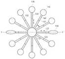
도 5를 참조하면, 이는 도 3의 평면도를 도시한 것으로, 중심부의 메인권심부(110)을 중심으로 다수의 단위권심부가 커넥팅유닛을 매개로 연결되어 있다.Referring to FIG. 5, which illustrates the plan view of FIG. 3, a plurality of unit cores are connected to the center of the
이 경우 다수의 단위권심부 중, 권취된 이차전지의 폴딩라인(folding line)을 형성하는 기준이 되는 제1권심부(120)가 한쌍이 상호 대향하는 위치에 배치되도록 하며, 상기 제1권심부(120)은 다른 단위 권심부의 형상과는 다른 형상으로 구현함이 바람직하다. 본 발명에 따른 실시예에서는 제1권심부(120)은 단면의 형상이 납작한 타원 형상, 구체적으로는 상기 메인권심부의 수평축(Y)방향으로 장변이 형성되는 타원구조의 단면을 구비하도록 구현할 수 있다.In this case, among the plurality of unit core parts, the
또한, 본 발명에 따른 단위 권심부는 상기 제1권심부(120) 이외에도 상기 제1권심부의 배치 위치의 상부인 제1영역 및 상기 제1영역에 대향하는 제2영역에 배치되는 다수의 제2권심부를 더 포함하여 구성될 수 있다.In addition, the unit winding unit according to the present invention, in addition to the
즉, 도 5의 평면도와 같이, 다수의 원통형 부재(130, 140)이 상기 제1권심부의 상부 영역 및 하부 영역에 더 배치되며, 전체적으로 제1권심부와 제2권심부의 외각이 원통형을 이루도록 구현할 수 있다.That is, as shown in the plan view of Figure 5, a plurality of cylindrical members (130, 140) are further disposed in the upper region and the lower region of the first core portion, the overall outer shell of the first core portion and the second core portion is cylindrical Can be implemented to achieve
또한, 상기 제2권심부(130, 140)는, 상기 제1영역 및 제2영역에 배치되는 단위권심부의 개수가 동일하도록 배치될 수 있으며, 이웃하는 단위권심부(130, 140) 간의 이격거리를 조절가능하도록 커넥팅유닛(131, 141)과 상기 메인권심부(110) 사이에 수평거리조절부(미도시)를 구비할 수 있다. 즉, 도시된 도면에서 단위권심부(120과 140) 사이의 폭을 좁힐 수 있도록, 상기 메인권시부(110) 상에 커넥팅 유닛의 거리를 늘리거나 줄일 수 있는 가이드 홈 등의 구조를 구현할 수 있다.In addition, the
또한, 본 발명에서 단위권심부의 길이를 조절할 수 있도록 케넉팅 유닛에 길이조절부(122, 132, 142)를 구비할 수 있다. 상기 길이조절부를 통해 전체 권취장치의 직경을 줄이거나 늘려서 이차전지의 크기를 조절할 수 있도록 할 수 있다. 이러한 길이 조절부는 커넥팅 유닛을 단위개체로 나누어 나사결합이나 슬라이딩 결합하는 구조로 길이 조절을 구현할 수 있다.In addition, in the present invention, the
도 6은 도 3 및 도 5의 단위권심부의 형상을 도시한 것이다.FIG. 6 illustrates the shape of the unit winding part of FIGS. 3 and 5.
(a)에 도시된 것은 제2권심부(130)의 구조로 원통형 구조를 도시한 것으로, 일정한 직경(T2)와 길이(T1)을 구비하는 구조로 길이(T1)은 전극조립체의 크기에 따라 가변될 수 있다. (b)에 도시된 것은 상술한 제1권심부(120)의 구조를 도시한 것으로, 폴딩라인을 구현하기 위해 장축과 단축을 가지는 타원형상의 단면을 가지는 구조로 도시한 것이다. 도시하지는 않았지만, 상기 단위권심부 자체의 길이를 조절할 수 있도록 구현하는 것도 가능하다. 즉 커넥팅 유닛의 길이 조절하는 것과 같이 단위권심부 자체를 분리 결합이 가능한 단위개체로 형성하고 결합을 통해 길이 조절이 가능한 유닛으로 구현할 수 있다.Shown in (a) is a structure of the
이상의 본 발명에 따른 권취장치는 다수의 단위권심으로 이루어지는 구조로 형성하여, 각형 이차전지의 선속도의 상이점으로 인한 와인딩(winding) 속도의 저해문제를 해소하고, 권취시 권취되는 전극에 가해지는 회전에 의한 전극 충격을 최소화할 수 있음은 물론, 커넥팅 유닛의 길이 조절을 통해 다양한 전지 사이즈에도 대응할 수 있도록 할 수 있다.The winding apparatus according to the present invention is formed in a structure consisting of a plurality of unit windings, to solve the problem of inhibiting the winding speed (winding) due to the difference in the linear speed of the rectangular secondary battery, the rotation applied to the electrode wound during winding By minimizing the impact of the electrode by the electrode, it is possible to cope with various battery sizes by adjusting the length of the connecting unit.
본 발명에 따른 권취장치에 의해 권취된 전극조립체는 권취장치에서 분리된 후 가압공정을 통해 각형 이차전지로 구현할 수 있게 된다.The electrode assembly wound by the winding apparatus according to the present invention can be implemented as a rectangular secondary battery through a pressing process after being separated from the winding apparatus.
또한, 이러한 제조공정을 통해 제조된 양극과 음극의 전기화학적 반응에 의해 전기를 생산하는 전기화학셀에 적용될 수 있는 바, 전기화학 셀의 대표적인 예로는, 슈퍼 캐패시터(super capacitor), 울트라 캐패시터(ultra capacitor), 이차전지, 연료전지, 각종 센서, 전기분해장치, 전기화학적 반응기 등에 적용될 수 있다.In addition, it can be applied to the electrochemical cell that produces electricity by the electrochemical reaction of the positive electrode and the negative electrode produced through such a manufacturing process, representative examples of the electrochemical cell, super capacitor (super capacitor), ultra capacitor (ultra) capacitor), secondary battery, fuel cell, various sensors, electrolysis device, electrochemical reactor and the like.
특히, 이러한 전극조립체를 포함하는 이차전지는 충방전이 가능한 전극조립체가 이온 함유 전해액으로 함침된 상태에서 전지케이스에 내장되어 있는 구조로 이루어져 있으며, 하나의 바람직한 예에서, 상기 이차전지는 리튬 이차전지일 수 있다.In particular, the secondary battery including the electrode assembly has a structure in which the electrode assembly capable of charging and discharging is embedded in a battery case in a state impregnated with an electrolyte containing an ion, and in one preferred embodiment, the secondary battery is a lithium secondary battery. Can be.
최근 리튬 이차전지는 소형 모바일 기기뿐만 아니라 대형 디바이스의 전원으로 많은 관심을 모으고 있으며, 그러한 분야에의 적용 시 작은 중량을 가지는 것이 바람직하다. 이차전지의 중량을 줄이는 하나의 방안으로서, 알루미늄 라미네이트 시트의 파우치형 케이스에 전극조립체를 내장한 구조가 바람직할 수 있다. 이러한 리튬 이차전지에 대해서는 당업계에 공지되어 있으므로 본 명세서에는 관련 설명을 생략한다.Recently, a lithium secondary battery has attracted much attention as a power source for large devices as well as small mobile devices, and it is desirable to have a small weight when applied to such a field. As one way to reduce the weight of the secondary battery, a structure in which the electrode assembly is incorporated in a pouch type case of an aluminum laminate sheet may be preferable. Since such a lithium secondary battery is known in the art, the description thereof will be omitted.
또한, 앞서 설명한 바와 같이, 중대형 디바이스의 전원으로 사용할 때에는, 장기간의 사용시에도 작동 성능의 저하 현상을 최대한 억제하고, 수명 특성이 우수하며, 저렴한 비용으로 대량 생산할 수 있는 구조의 이차전지가 바람직하다. 이러한 관점에서 본 발명의 전극조립체를 포함하는 이차전지는 이를 단위전지로 하는 중대형 전지모듈에 바람직하게 사용될 수 있다.In addition, as described above, when used as a power source for a medium-to-large device, a secondary battery having a structure capable of minimizing the deterioration of operation performance even during long-term use, having excellent life characteristics, and capable of mass production at low cost is preferable. In this regard, the secondary battery including the electrode assembly of the present invention may be preferably used in a medium-large battery module having the unit cell.
다수의 이차전지를 포함하는 전지 모듈을 포함하는 전지 팩의 경우, 파워 툴(power tool); 전기차(Electric Vehicle, EV), 하이브리드 전기차(Hybrid Electric Vehicle, HEV) 및 플러그인 하이브리드 전기차(Plug-in Hybrid Electric Vehicle, PHEV)로 이루어진 군에서 선택된 전기차; 이-바이크(E-bike); 이-스쿠터(E-scooter); 전기 골프 카트(Electric golf cart); 전기 트럭; 및 전기 상용차로 이루어진 중대형 디바이스 군에서 선택된 하나 이상의 전원으로 사용될 수 있다.In the case of a battery pack including a battery module including a plurality of secondary batteries, a power tool (power tool); Electric vehicles selected from the group consisting of electric vehicles (EVs), hybrid electric vehicles (HEVs), and plug-in hybrid electric vehicles (PHEVs); E-bikes; E-scooters; Electric golf cart; Electric truck; And it can be used as one or more power source selected from the medium-large device group consisting of electric commercial vehicles.
중대형 전지모듈은 다수의 단위전지들을 직렬 방식 또는 직렬/병렬 방식으로 연결하여 고출력 대용량을 제공하도록 구성되어 있으며, 그에 대해서는 당업계에 공지되어 있으므로 본 명세서에는 관련 설명을 생략한다.The medium-large battery module is configured to provide a high output capacity by connecting a plurality of unit cells in series or in series / parallel manner, which is well known in the art, and thus, description thereof is omitted herein.
전술한 바와 같은 본 발명의 상세한 설명에서는 구체적인 실시예에 관해 설명하였다. 그러나 본 발명의 범주에서 벗어나지 않는 한도 내에서는 여러 가지 변형이 가능하다. 본 발명의 기술적 사상은 본 발명의 기술한 실시예에 국한되어 정해져서는 안 되며, 특허청구범위뿐만 아니라 이 특허청구범위와 균등한 것들에 의해 정해져야 한다.In the foregoing detailed description of the present invention, specific examples have been described. However, various modifications are possible within the scope of the present invention. The technical idea of the present invention should not be limited to the embodiments of the present invention but should be determined by the equivalents of the claims and the claims.
110: 메인권심부
120, 130, 140: 단위권심부
121, 131, 141: 커넥팅유닛
122, 132, 142: 길이조절수단110: Main Heartland
120, 130, 140: unit core
121, 131, 141: connecting unit
122, 132, 142: length adjusting means
Claims (11)
Translated fromKorean축회전을 수행하며 극판을 권취하는 메인권심부;
상기 메인권심부에 일단이 결합되어 외부방향으로 연장되는 커넥팅유닛; 및
상기 지지부재의 타단에 연결되는 다수의 단위권심부;
를 포함하는 이차전지의 권취장치.
In the winding device of a secondary battery,
A main winding portion for winding the plate while performing axial rotation;
A connecting unit having one end coupled to the main core part and extending outwardly; And
A plurality of unit windings connected to the other end of the support member;
Winding device of a secondary battery comprising a.
상기 단위권심부는,
상기 메인권심부의 상부 방향으로 일정한 길이를 구비하는 바타입(bar type)의 구조물로,
권취되는 이차전지의 권취부재와 맞닿는 면이 곡률이 형성되는 이차전지의 권취장치.
The method according to claim 1,
The unit core portion,
The structure of the bar type (bar type) having a predetermined length in the upper direction of the main core,
A winding device of a secondary battery, wherein a surface of the secondary battery being wound is in contact with the winding member.
상기 단위권심부는,
단면의 형상이 원형 또는 타원형의 구조물인 이차전지의 권취장치.
The method according to claim 2,
The unit core portion,
Winding device of a secondary battery having a cross-sectional shape of a circular or elliptical structure.
상기 단위권심부는,
권취된 이차전지의 폴딩라인(folding line)을 형성하는 기준이 되는 제1권심부를 포함하는 이차전지의 권취장치.
The method according to claim 1,
The unit core portion,
A secondary battery winding apparatus including a first core part serving as a reference for forming a folding line of a wound secondary battery.
상기 제1권심부는,
상기 메인권심부의 양측에 한쌍이 대향하는 위치에 배치되는 구조로 형성되는 이차전지의 권취장치.
The method of claim 4,
The first core part,
A secondary battery winding apparatus, which is formed in a structure in which a pair is disposed at opposite sides of the main winding portion.
상기 제1권심부는,
다른 단위권심부의 단면의 형상과 상이한 구조로 형성되는 이차전지의 권취장치.
The method according to claim 5,
The first core part,
A secondary battery winding apparatus formed with a structure different from the shape of the cross section of another unit winding part.
상기 제1권심부는,
상기 메인권심부의 수평축(Y)방향으로 장변이 형성되는 타원구조의 단면을 구비하는 이차전지의 권취장치.
The method of claim 6,
The first core part,
A secondary battery winding device having a cross section of an elliptic structure in which a long side is formed in a horizontal axis (Y) direction of the main core part.
상기 단위권심부는,
상기 제1권심부의 배치 위치의 상부인 제1영역 및 상기 제1영역에 대향하는 제2영역에 배치되는 다수의 제2권심부를 더 포함하는 이차전지의 권취장치.
The method according to claim 5,
The unit core portion,
And a plurality of second winding parts disposed in a first area that is an upper portion of the arrangement position of the first winding part and a second area that faces the first area.
상기 제2권심부는,
상기 제1영역 및 제2영역에 배치되는 단위권심부의 개수가 동일한 것을 특징으로 하는 이차전지의 권취장치.
The method according to claim 8,
The second core part,
The secondary battery winding apparatus of claim 1, wherein the number of unit windings disposed in the first region and the second region is the same.
상기 다수의 제2권심부는,
이웃하는 단위권심부 간의 이격거리를 조절가능하도록 커넥팅유닛과 상기 메인권심부 사이에 수평거리조절부를 더 포함하는 이차전지의 권취장치.
The method of claim 9,
The plurality of second core portion,
And a horizontal distance control unit between the connecting unit and the main winding unit so as to adjust a separation distance between neighboring unit winding units.
상기 커넥팅유닛은,
상기 메인권심부의 내부방향 또는 외부 방향으로 길이를 조절할 수 있는 길이조절부를 더 포함하는 이차전지의 권취장치.The method according to any one of claims 1 to 10,
The connecting unit,
Winding device of the secondary battery further comprises a length adjusting unit for adjusting the length in the inner or outer direction of the main winding.
Priority Applications (1)
| Application Number | Priority Date | Filing Date | Title |
|---|---|---|---|
| KR1020120080556AKR101528002B1 (en) | 2012-07-24 | 2012-07-24 | Rolling Device for Lithium ion Secondary battery |
Applications Claiming Priority (1)
| Application Number | Priority Date | Filing Date | Title |
|---|---|---|---|
| KR1020120080556AKR101528002B1 (en) | 2012-07-24 | 2012-07-24 | Rolling Device for Lithium ion Secondary battery |
Publications (2)
| Publication Number | Publication Date |
|---|---|
| KR20140014492Atrue KR20140014492A (en) | 2014-02-06 |
| KR101528002B1 KR101528002B1 (en) | 2015-06-10 |
Family
ID=50264373
Family Applications (1)
| Application Number | Title | Priority Date | Filing Date |
|---|---|---|---|
| KR1020120080556AActiveKR101528002B1 (en) | 2012-07-24 | 2012-07-24 | Rolling Device for Lithium ion Secondary battery |
Country Status (1)
| Country | Link |
|---|---|
| KR (1) | KR101528002B1 (en) |
Cited By (1)
| Publication number | Priority date | Publication date | Assignee | Title |
|---|---|---|---|---|
| KR20190030977A (en)* | 2017-09-15 | 2019-03-25 | 삼성에스디아이 주식회사 | Apparatus for winding electrode assembly |
Family Cites Families (2)
| Publication number | Priority date | Publication date | Assignee | Title |
|---|---|---|---|---|
| JP2005116492A (en)* | 2003-10-06 | 2005-04-28 | Kaido Seisakusho:Kk | Battery device winding device (roller outer diameter variable type) meandering correction device |
| KR101165462B1 (en)* | 2005-07-26 | 2012-07-12 | 삼성에스디아이 주식회사 | Pole plate winding device |
- 2012
- 2012-07-24KRKR1020120080556Apatent/KR101528002B1/enactiveActive
Cited By (1)
| Publication number | Priority date | Publication date | Assignee | Title |
|---|---|---|---|---|
| KR20190030977A (en)* | 2017-09-15 | 2019-03-25 | 삼성에스디아이 주식회사 | Apparatus for winding electrode assembly |
Also Published As
| Publication number | Publication date |
|---|---|
| KR101528002B1 (en) | 2015-06-10 |
Similar Documents
| Publication | Publication Date | Title |
|---|---|---|
| US9698398B2 (en) | Secondary battery module | |
| EP2779269B1 (en) | Battery cell having a novel structure | |
| US20100075210A1 (en) | Hybrid-Typed Electrode Assembly of Capacitor-Battery Structure | |
| KR101983391B1 (en) | Cooling Device for Battery Module and Battery Module Assembly having the same | |
| US9935329B2 (en) | Stepped electrode group stack | |
| WO2005013408A1 (en) | Lithium ion secondary cell | |
| JP5994977B2 (en) | Secondary battery | |
| KR101622437B1 (en) | Press device for jelly roll-secondary battery and Fabricating method of secondary battery using the same | |
| KR101888207B1 (en) | Zig for stacking battery cell | |
| US9437898B2 (en) | Secondary battery including plurality of electrode assemblies | |
| CN113711406A (en) | Secondary battery | |
| KR101551531B1 (en) | Rolling member, Rolling Device for Lithium ion Secondary battery of using the same, Rolling method of using the same | |
| KR101154872B1 (en) | Electrode Assembly of Novel Structure | |
| US20210028494A1 (en) | Unit cell and method for manufacturing the same | |
| US11322799B2 (en) | Electrode including single-sided electrode with inorganic coating layer attached to slurry on collector and electrode assembly including the same | |
| US9761857B2 (en) | Electrode assembly for secondary battery | |
| KR20060087180A (en) | Separator and secondary battery having same | |
| KR101888208B1 (en) | Zig for stacking battery cell | |
| KR101590671B1 (en) | Ultrasonic welding assembly and Fabricating method of secondary battery using the same | |
| KR101403383B1 (en) | Cylindrical Secondary Battery of Improved Safety | |
| KR20190082180A (en) | Secondary Battery Module | |
| KR101528002B1 (en) | Rolling Device for Lithium ion Secondary battery | |
| KR20080047153A (en) | Secondary battery | |
| KR101590672B1 (en) | Ultrasonic welding assembly and Fabricating method of secondary battery using the same | |
| KR20200056376A (en) | Secondary Battery Module |
Legal Events
| Date | Code | Title | Description |
|---|---|---|---|
| PA0109 | Patent application | Patent event code:PA01091R01D Comment text:Patent Application Patent event date:20120724 | |
| A201 | Request for examination | ||
| PA0201 | Request for examination | Patent event code:PA02012R01D Patent event date:20130916 Comment text:Request for Examination of Application Patent event code:PA02011R01I Patent event date:20120724 Comment text:Patent Application | |
| PG1501 | Laying open of application | ||
| E902 | Notification of reason for refusal | ||
| PE0902 | Notice of grounds for rejection | Comment text:Notification of reason for refusal Patent event date:20141224 Patent event code:PE09021S01D | |
| E701 | Decision to grant or registration of patent right | ||
| PE0701 | Decision of registration | Patent event code:PE07011S01D Comment text:Decision to Grant Registration Patent event date:20150403 | |
| GRNT | Written decision to grant | ||
| PR0701 | Registration of establishment | Comment text:Registration of Establishment Patent event date:20150604 Patent event code:PR07011E01D | |
| PR1002 | Payment of registration fee | Payment date:20150604 End annual number:3 Start annual number:1 | |
| PG1601 | Publication of registration | ||
| FPAY | Annual fee payment | Payment date:20180418 Year of fee payment:4 | |
| PR1001 | Payment of annual fee | Payment date:20180418 Start annual number:4 End annual number:4 | |
| FPAY | Annual fee payment | Payment date:20190401 Year of fee payment:5 | |
| PR1001 | Payment of annual fee | Payment date:20190401 Start annual number:5 End annual number:5 | |
| PR1001 | Payment of annual fee | Payment date:20200421 Start annual number:6 End annual number:6 | |
| PR1001 | Payment of annual fee | Payment date:20210518 Start annual number:7 End annual number:7 | |
| PR1001 | Payment of annual fee | Payment date:20220502 Start annual number:8 End annual number:8 | |
| PR1001 | Payment of annual fee | Payment date:20240319 Start annual number:10 End annual number:10 |