KR20140012697A - Infrared sensor - Google Patents
Infrared sensorDownload PDFInfo
- Publication number
- KR20140012697A KR20140012697AKR1020137025541AKR20137025541AKR20140012697AKR 20140012697 AKR20140012697 AKR 20140012697AKR 1020137025541 AKR1020137025541 AKR 1020137025541AKR 20137025541 AKR20137025541 AKR 20137025541AKR 20140012697 AKR20140012697 AKR 20140012697A
- Authority
- KR
- South Korea
- Prior art keywords
- insulating film
- film
- infrared
- sensor
- heat sensitive
- Prior art date
- Legal status (The legal status is an assumption and is not a legal conclusion. Google has not performed a legal analysis and makes no representation as to the accuracy of the status listed.)
- Ceased
Links
Images


Classifications
- G—PHYSICS
- G01—MEASURING; TESTING
- G01J—MEASUREMENT OF INTENSITY, VELOCITY, SPECTRAL CONTENT, POLARISATION, PHASE OR PULSE CHARACTERISTICS OF INFRARED, VISIBLE OR ULTRAVIOLET LIGHT; COLORIMETRY; RADIATION PYROMETRY
- G01J5/00—Radiation pyrometry, e.g. infrared or optical thermometry
- G01J5/0096—Radiation pyrometry, e.g. infrared or optical thermometry for measuring wires, electrical contacts or electronic systems
- G—PHYSICS
- G01—MEASURING; TESTING
- G01J—MEASUREMENT OF INTENSITY, VELOCITY, SPECTRAL CONTENT, POLARISATION, PHASE OR PULSE CHARACTERISTICS OF INFRARED, VISIBLE OR ULTRAVIOLET LIGHT; COLORIMETRY; RADIATION PYROMETRY
- G01J5/00—Radiation pyrometry, e.g. infrared or optical thermometry
- G01J5/02—Constructional details
- G01J5/0205—Mechanical elements; Supports for optical elements
- G—PHYSICS
- G01—MEASURING; TESTING
- G01J—MEASUREMENT OF INTENSITY, VELOCITY, SPECTRAL CONTENT, POLARISATION, PHASE OR PULSE CHARACTERISTICS OF INFRARED, VISIBLE OR ULTRAVIOLET LIGHT; COLORIMETRY; RADIATION PYROMETRY
- G01J5/00—Radiation pyrometry, e.g. infrared or optical thermometry
- G01J5/02—Constructional details
- G01J5/0225—Shape of the cavity itself or of elements contained in or suspended over the cavity
- G01J5/023—Particular leg structure or construction or shape; Nanotubes
- G—PHYSICS
- G01—MEASURING; TESTING
- G01J—MEASUREMENT OF INTENSITY, VELOCITY, SPECTRAL CONTENT, POLARISATION, PHASE OR PULSE CHARACTERISTICS OF INFRARED, VISIBLE OR ULTRAVIOLET LIGHT; COLORIMETRY; RADIATION PYROMETRY
- G01J5/00—Radiation pyrometry, e.g. infrared or optical thermometry
- G01J5/02—Constructional details
- G01J5/04—Casings
- G01J5/046—Materials; Selection of thermal materials
- G—PHYSICS
- G01—MEASURING; TESTING
- G01J—MEASUREMENT OF INTENSITY, VELOCITY, SPECTRAL CONTENT, POLARISATION, PHASE OR PULSE CHARACTERISTICS OF INFRARED, VISIBLE OR ULTRAVIOLET LIGHT; COLORIMETRY; RADIATION PYROMETRY
- G01J5/00—Radiation pyrometry, e.g. infrared or optical thermometry
- G01J5/02—Constructional details
- G01J5/05—Means for preventing contamination of the components of the optical system; Means for preventing obstruction of the radiation path
- G—PHYSICS
- G01—MEASURING; TESTING
- G01J—MEASUREMENT OF INTENSITY, VELOCITY, SPECTRAL CONTENT, POLARISATION, PHASE OR PULSE CHARACTERISTICS OF INFRARED, VISIBLE OR ULTRAVIOLET LIGHT; COLORIMETRY; RADIATION PYROMETRY
- G01J5/00—Radiation pyrometry, e.g. infrared or optical thermometry
- G01J5/02—Constructional details
- G01J5/06—Arrangements for eliminating effects of disturbing radiation; Arrangements for compensating changes in sensitivity
- G01J5/061—Arrangements for eliminating effects of disturbing radiation; Arrangements for compensating changes in sensitivity by controlling the temperature of the apparatus or parts thereof, e.g. using cooling means or thermostats
- G—PHYSICS
- G01—MEASURING; TESTING
- G01J—MEASUREMENT OF INTENSITY, VELOCITY, SPECTRAL CONTENT, POLARISATION, PHASE OR PULSE CHARACTERISTICS OF INFRARED, VISIBLE OR ULTRAVIOLET LIGHT; COLORIMETRY; RADIATION PYROMETRY
- G01J5/00—Radiation pyrometry, e.g. infrared or optical thermometry
- G01J5/02—Constructional details
- G01J5/08—Optical arrangements
- G01J5/0875—Windows; Arrangements for fastening thereof
- G—PHYSICS
- G01—MEASURING; TESTING
- G01J—MEASUREMENT OF INTENSITY, VELOCITY, SPECTRAL CONTENT, POLARISATION, PHASE OR PULSE CHARACTERISTICS OF INFRARED, VISIBLE OR ULTRAVIOLET LIGHT; COLORIMETRY; RADIATION PYROMETRY
- G01J5/00—Radiation pyrometry, e.g. infrared or optical thermometry
- G01J5/10—Radiation pyrometry, e.g. infrared or optical thermometry using electric radiation detectors
- G01J5/20—Radiation pyrometry, e.g. infrared or optical thermometry using electric radiation detectors using resistors, thermistors or semiconductors sensitive to radiation, e.g. photoconductive devices
Landscapes
- Physics & Mathematics (AREA)
- General Physics & Mathematics (AREA)
- Spectroscopy & Molecular Physics (AREA)
- Chemical & Material Sciences (AREA)
- Engineering & Computer Science (AREA)
- Nanotechnology (AREA)
- Photometry And Measurement Of Optical Pulse Characteristics (AREA)
- Radiation Pyrometers (AREA)
Abstract
Translated fromKoreanDescription
Translated fromKorean본 발명은 측정 대상물로부터의 적외선을 검지하여 그 측정 대상물의 온도 등을 측정하는 적외선 센서에 관한 것이다.The present invention relates to an infrared sensor that detects infrared rays from an object to be measured and measures the temperature and the like of the object to be measured.
FET 등의 스위칭 소자나 전해 콘덴서 등, 회로 기판 상의 전자 부품 (디바이스) 의 발열 상태를 검지하는 경우, 디바이스 근방의 회로 기판 상에 온도 센서를 설치하거나, 디바이스에 접속된 히트 싱크에 온도 센서를 설치하고, 회로 기판이나 히트 싱크의 온도로부터 간접적으로 소자 온도를 알 수 있는 방법이 알려져 있다. 이 방법에서는, 간접적으로 디바이스 등의 측정 대상물의 온도를 검출하기 때문에, 검출 오차가 커 고정밀의 검출이 어렵다.When detecting a heat generation state of an electronic component (device) on a circuit board such as a switching element such as an FET or an electrolytic capacitor, a temperature sensor is provided on a circuit board near the device or a temperature sensor is installed in a heat sink connected to the device. Then, the method of knowing the element temperature indirectly from the temperature of a circuit board or a heat sink is known. In this method, since the temperature of a measurement object such as a device is detected indirectly, the detection error is large and high accuracy detection is difficult.
한편, 종래, 측정 대상물로부터 방사되는 적외선을 비접촉으로 검지하여 측정 대상물의 온도를 측정하는 온도 센서로서, 적외선 센서가 사용되고 있다.On the other hand, the infrared sensor is conventionally used as a temperature sensor which detects the infrared rays radiate | emitted from a measurement object non-contact and measures the temperature of a measurement object.
예를 들어, 특허문헌 1 에는, 복사기의 정착 장치에 사용되고 있는 가열 정착 롤러 등의 온도를 측정하는 온도 센서로서, 유지체에 설치한 수지 필름과, 그 수지 필름에 형성되어 유지체의 도광부를 통하여 적외선을 검지하는 적외선 검지용 감열 소자와, 수지 필름에 차광 상태로 형성되어 유지체의 온도를 검지하는 온도 보상용 감열 소자를 구비한 적외선 센서가 제안되어 있다. 이 적외선 센서에서는, 도광부의 내측면에 적외선 흡수막을 형성함과 함께, 수지 필름에 카본 블랙 등의 적외선 흡수 재료를 함유시켜 적외선의 흡수를 높이고 있다. 또, 이 적외선 센서에서는, 열전도율이 크고 열방사율이 작은 알루미늄 등의 금속 재료로 대략 블록 상으로 형성된 하우징인 유지체에 감열 소자가 내장되어 있다.For example,
또, 특허문헌 2 에는, 적외선 검지용 감열 소자와, 온도 보상용 감열 소자와, 이들을 밀착 고정시키는 수지 필름과, 적외선의 입사창측에 적외선 검지용 감열 소자를 배치함과 함께 적외선을 차폐하는 차폐부측에 온도 보상용 감열 소자를 배치한 프레임체를 갖는 케이스를 구비한 적외선 검출기가 제안되어 있다.In addition,
이 적외선 검출기에서는, 수지 필름에 카본 블랙 등의 적외선 흡수 재료를 함유시켜 적외선의 흡수를 높이고 있음과 함께, 적외선 검지용 감열 소자와 온도 보상용 감열 소자의 열구배를 없애기 위해 열 전도가 양호한 재료로 프레임체를 형성하고 있다. 또, 적외선 검지용 감열 소자 및 온도 보상용 감열 소자에는, 리드선이 서미스터에 접속된 래디얼 리드형 서미스터가 채용되어 있다. 또한, 이 적외선 검출기는, 수지 또는 금속으로 형성된 케이스에 감열 소자가 내장되어 있다.In this infrared detector, an infrared absorbing material such as carbon black is contained in the resin film to increase absorption of infrared rays, and a material having good thermal conduction in order to eliminate thermal gradients between the thermal sensing element for infrared detection and the thermal element for temperature compensation. The frame body is formed. Moreover, the radial lead type thermistor in which a lead wire is connected to the thermistor is employ | adopted as the thermal element for infrared detection and the thermal element for temperature compensation. In addition, this infrared detector has a thermosensitive element incorporated in a case formed of resin or metal.
이들 특허문헌 1 및 2 의 적외선 센서에서는, 수지 필름에 카본 블랙 등의 적외선 흡수 재료를 함유시킴과 함께 일방의 감열 소자측을 온도 보상용으로 차광하는 구조가 채용되어 있지만, 적외선 흡수 재료를 함유한 수지 필름의 열 전도가 높고, 적외선 검지용과 온도 보상용의 감열 소자 사이에서 온도차분이 발생하기 어렵다는 문제가 있었다. 또, 이들 감열 소자 사이에서 온도차분을 크게 하기 위해서는, 감열 소자간의 거리를 크게 할 필요가 있어, 전체 형상이 커져, 소형화가 곤란해지는 문제가 있다. 또한, 온도 보상용 감열 소자를 차광하는 구조를 케이스 자체에 형성할 필요가 있기 때문에, 고가가 되어 버린다. 또, 특허문헌 2 에서는, 열 전도가 양호한 프레임체를 채용하고 있기 때문에, 적외선 흡수막으로부터의 열도 방열되어 감도가 열화되는 문제가 있다. 또, 리드선이 접속된 래디얼 리드형이기 때문에, 서미스터와 리드선 사이에서 열의 공간 전도가 발생한다. 또한, 일방의 감열 소자에 대하여 적외선을 하우징으로 차광하는 구조를 채용하고 있지만, 적외선을 차단하고 있는 것만으로 차폐 부분이 적외선을 흡수하여, 차폐 부분의 온도가 변화되기 때문에 레퍼런스로서 불완전해지는 문제가 있었다.In the infrared sensors of these
그 때문에, 특허문헌 3 에 나타내는 바와 같이, 절연성 필름과, 그 절연성 필름의 일방의 면에 서로 이간시켜 형성된 제 1 감열 소자 및 제 2 감열 소자와, 절연성 필름의 일방의 면에 형성되어 제 1 감열 소자 및 제 2 감열 소자에 각각 접속된 복수 쌍의 도전성 배선막과, 제 1 감열 소자에 대향하여 절연성 필름의 타방의 면에 형성된 적외선 흡수막과, 제 2 감열 소자에 대향하여 절연성 필름의 타방의 면에 형성된 적외선 반사막을 구비하고 있는 적외선 센서가 개발되어 있다.Therefore, as shown in
이 적외선 센서에서는, 적외선 흡수막을 형성한 부분에서는 적외선을 흡수하여, 적외선 반사막을 형성한 부분에서는 적외선을 반사함으로써, 얇고 열 전도성이 낮은 절연성 필름 상에서 제 1 감열 소자와 제 2 감열 소자 사이에 양호한 온도차분을 얻을 수 있다. 즉, 필름에 적외선 흡수 재료 등을 함유시키지 않은 저열전도성의 절연성 필름에서도, 적외선 흡수막에 의해 절연성 필름의 제 1 감열 소자의 바로 윗부분에만 적외선 흡수에 의한 열을 전도시킬 수 있다. 특히, 얇은 절연성 필름을 사이에 두고 적외선 흡수막의 열이 전도되기 때문에, 감도의 열화가 없고, 높은 응답성을 갖고 있다. 또, 적외선 흡수막의 면적을 임의로 설정할 수 있기 때문에, 측정 대상물과의 거리에 맞춘 적외선 검출의 시야각을 면적으로 설정할 수 있어, 높은 수광 효율을 얻을 수 있다. 또, 적외선 반사막에 의해 절연성 필름의 제 2 감열 소자의 바로 윗부분에 있어서의 적외선을 반사하여 그 흡수를 저지할 수 있다. 또한, 절연성 필름 상에 적외선 흡수막과 적외선 반사막을 형성하고 있기 때문에, 적외선 흡수막과 적외선 반사막 사이의 열을 전도하는 매체가, 공기 이외에는 이들 막이 대향한 동안의 절연성 필름만이 되어, 전도하는 단면적이 작아진다. 따라서, 상호의 감열 소자로의 열이 전달되기 어려워지고, 열간섭이 적어져 검출 감도가 향상된다. 이와 같이, 저열전도성의 절연성 필름 상에서 서로 열의 영향이 억제된 제 1 감열 소자와 제 2 감열 소자가 각각 적외선 흡수막의 바로 아래와 적외선 반사막의 바로 아래의 절연성 필름의 부분적인 온도를 측정하는 구조를 갖고 있다. 따라서, 적외선 검지용이 되는 제 1 감열 소자와 온도 보상용이 되는 제 2 감열 소자 사이에 양호한 온도차분을 얻을 수 있어, 고감도화를 도모할 수 있다.In this infrared sensor, infrared rays are absorbed at the portion where the infrared absorbing film is formed, and infrared rays are reflected at the portion where the infrared reflecting film is formed, thereby providing a good temperature between the first thermal element and the second thermal element on the thin and low thermal insulating film. You can get a difference. That is, even in the low thermal conductivity insulating film which does not contain an infrared absorbing material etc. in a film, heat by infrared absorption can be conducted only to the upper part of the 1st heat sensitive element of an insulating film by an infrared absorbing film. In particular, since heat of the infrared absorbing film is conducted with a thin insulating film interposed therebetween, there is no deterioration of sensitivity and high responsiveness. Moreover, since the area of the infrared absorbing film can be arbitrarily set, the viewing angle of infrared detection according to the distance to the measurement object can be set as the area, and high light receiving efficiency can be obtained. Moreover, the infrared reflecting film in the upper part of the 2nd heat sensitive element of an insulating film can be reflected by an infrared reflecting film, and the absorption can be suppressed. In addition, since the infrared absorbing film and the infrared reflecting film are formed on the insulating film, the medium that conducts heat between the infrared absorbing film and the infrared reflecting film becomes only the insulating film while these films are opposed to each other except for air, and the cross-sectional area of conducting the film is confined. Becomes smaller. Therefore, it becomes difficult to transfer heat to each other's thermal elements, and thermal interference is reduced, so that detection sensitivity is improved. As described above, the first and second heat sensitive elements each of which the influence of heat is suppressed on the low thermal conductive insulating film each have a structure in which a partial temperature of the insulating film directly under the infrared absorbing film and directly under the infrared reflecting film is measured. . Therefore, a favorable temperature difference can be obtained between the 1st thermosensitive element used for infrared detection, and the 2nd thermosensitive element used for temperature compensation, and high sensitivity can be aimed at.
상기 종래 기술에는 이하의 과제가 남아 있다. 특허문헌 1 내지 3 에 기재된 적외선 센서를 장착하는 경우, 블록상의 하우징 또는 케이스를 장착하기 위해 큰 전용의 장착 구조 및 지지 구조를 채용할 필요가 있어, 넓은 설치 스페이스를 확보해야 함과 함께 고비용이 되는 문제가 있었다. 또, 예를 들어, 도 7 에 나타내는 바와 같이, 적외선 센서로서 서모파일 (101) 을 수직으로 세운 실장 기판 (102) 에 고정시켜 디바이스의 횡방향으로부터 온도를 검출하는 것도 생각할 수 있지만, 이 경우, 서모파일 (101) 이 금속 캔에 봉지된 구조로, 큰 용적을 가져 두껍기 때문에 상기 각 특허문헌과 마찬가지로 넓은 설치 면적 및 공간이 필요해진다는 문제가 있었다. 이 때문에, 적외선 센서가 탑재되는 장치 또는 회로 기판 전체의 소형화 및 고밀도화가 곤란해지는 문제가 있었다. 또, 서모파일 (101) 이 무겁기 때문에, 실장 기판 (102) 을 회로 기판 (104) 에 수직으로 세우려면, 큰 지지 부재 (103) 등의 지지 구조에 의해 높은 지지 강도를 얻을 필요가 있었다. 특히, 도 8 에 나타내는 바와 같이, 측정 대상물 (S) 의 온도를 측정하고자 하는 부분 (S1) 이 회로 기판 (104) 의 표면으로부터 떨어져 있는 경우, 검출 위치까지의 높이 (거리) 를 확보하기 위해 실장 기판 (102) 이 길어져, 차재용 등에서는, 진동에 의해 회로 기판 (104) 에 대한 실장 기판 (102) 의 고정이 느슨해질 우려가 있음과 함께, 실장 기판 (102) 이 흔들려 적외선의 시야각이 흔들리거나, 진동 잡음이 더해져 검출 정밀도가 열화되는 문제가 있었다. 또한, 서모파일 (101) 의 납땜 등이 필요해지고, 장착 공정이 많아져, 비용의 증대를 초래한다는 문제가 있었다.The following problems remain in the prior art. In the case of mounting the infrared sensors described in
본 발명은 전술한 과제를 감안하여 이루어진 것으로, 경량이고 또한 안정적인 설치 상태를 얻을 수 있어, 회로 기판으로부터 떨어진 부분의 온도도 고정밀도로 검출할 수 있음과 함께 용이하게 부착할 수 있는 적외선 센서를 제공하는 것을 목적으로 한다.SUMMARY OF THE INVENTION The present invention has been made in view of the above-described problems, and it is possible to obtain a light and stable installation state, and to provide an infrared sensor which can easily detect the temperature of a part away from the circuit board and can be easily attached. For the purpose of
본 발명은 상기 과제를 해결하기 위해 이하의 구성을 채용하였다. 즉, 제 1 발명의 적외선 센서는, 절연성 필름과, 그 절연성 필름의 일방의 면에 서로 이간시켜 형성된 제 1 감열 소자 및 제 2 감열 소자와, 상기 절연성 필름의 일방의 면에 형성되어 상기 제 1 감열 소자에 접속된 도전성의 제 1 배선막 및 상기 제 2 감열 소자에 접속된 도전성의 제 2 배선막과, 상기 제 2 감열 소자에 대향하여 상기 절연성 필름의 타방의 면에 형성된 적외선 반사막과, 상기 제 1 배선막 및 상기 제 2 배선막에 접속되고 상기 절연성 필름의 타방의 면에 있어서의 일단부에 형성되어 외부의 커넥터에 끼워넣을 수 있는 복수의 단자 전극과, 상기 절연성 필름의 일방의 면에 있어서의 일단부에 첩부 (貼付) 된 단부 보강판과, 상기 절연성 필름의 타단부에 형성된 장착용 구멍을 구비하고 있는 것을 특징으로 한다.The present invention adopts the following constitution to solve the above problems. That is, the infrared sensor of 1st invention is formed in the insulating film, the 1st heat sensitive element and the 2nd heat sensitive element which were formed by mutually spaced apart on one surface of this insulating film, and the one surface of the said insulating film, and is said 1st A conductive first wiring film connected to the thermosensitive element and a conductive second wiring film connected to the second thermosensitive element, an infrared reflecting film formed on the other side of the insulating film to face the second thermal sensing element, and A plurality of terminal electrodes connected to the first wiring film and the second wiring film and formed at one end of the other surface of the insulating film and inserted into an external connector, and to one surface of the insulating film. It is equipped with the edge part reinforcement board affixed on one end part in the end, and the mounting hole formed in the other end part of the said insulating film.
이 적외선 센서에서는, 절연성 필름의 일단부에 형성되어 외부의 커넥터에 끼워넣을 수 있는 복수의 단자 전극과, 절연성 필름의 일단부에 첩부된 단부 보강판과, 절연성 필름의 타단부에 형성된 장착용 구멍을 구비하고 있기 때문에, 단부 보강판에 의해 고강성이 된 일단부의 단자 전극을 커넥터에 끼워 넣음으로써 용이하게 회로 기판 등에 고정 및 전기적 접속을 할 수 있음과 함께, 커넥터로부터 떨어진 다른 외부 부재에 장착용 구멍을 이용하여 절연성 필름의 타단부를 나사 고정 등에 의해 고정시킬 수 있다. 이로써, 절연성 필름의 양단부가 고정되어 팽팽하게 설치된 상태가 되어, 전체가 안정적으로 지지됨으로써, 제 1 감열 소자, 제 2 감열 소자 및 적외선 반사막을 포함하는 센서부가 커넥터로부터 떨어져 배치되어 있더라도, 진동에 의해 센서부의 시야각 흔들리거나, 진동 잡음이 더해지거나 하는 것을 억제할 수 있다. 또, 절연성 필름이 유연하므로, 장착용 구멍에 의한 타단부의 장착 위치를 커넥터 바로 윗쪽으로부터 어긋나게 할 수도 있고, 센서부의 기울기를 바꿔 적외선의 검출 방향을 임의로 변경할 수도 있다. 따라서, 회로 기판 상에 리플로우로 실장한 커넥터에 일단부를 꽂아 넣음과 함께 타단부를 장착용 구멍을 이용하여 고정시키는 것만으로 용이하게 장착할 수 있고, 좁은 설치 스페이스에서도 실장할 수 있어, 고밀도화에도 적합하고, 또한 회로 기판으로부터 떨어진 위치의 온도도 고정밀도로 검출할 수 있게 된다.In this infrared sensor, a plurality of terminal electrodes formed at one end of the insulating film and inserted into an external connector, an end reinforcement plate attached to one end of the insulating film, and a mounting hole formed at the other end of the insulating film Since the terminal electrode is inserted into the connector of the terminal electrode of the one end which has become highly rigid by the end reinforcement board, it can be easily fixed and electrically connected to a circuit board or the like and is mounted to another external member away from the connector. Using the hole, the other end of the insulating film can be fixed by screwing or the like. As a result, both ends of the insulating film are fixed to be in a state in which the whole is stably supported, whereby the sensor part including the first heat sensing element, the second heat sensing element, and the infrared reflecting film is separated from the connector by vibration. The viewing angle of the sensor portion can be suppressed from being shaken or the addition of vibration noise. Moreover, since an insulating film is flexible, the mounting position of the other end part by a mounting hole can shift | deviate from directly above a connector, and the inclination of a sensor part can be changed and the detection direction of infrared rays can be changed arbitrarily. Therefore, one end can be easily inserted by simply inserting one end into a reflow-mounted connector on a circuit board and fixing the other end by using a mounting hole. It is possible to detect the temperature at a suitable position and away from the circuit board with high accuracy.
또, 제 2 발명의 적외선 센서는, 제 1 발명에 있어서, 상기 제 1 감열 소자, 상기 제 2 감열 소자 및 상기 적외선 반사막의 영역에 대응한 센서부용 창부가 형성되고 상기 절연성 필름의 일방의 면에 상기 영역을 둘러싸고 첩부된 센서부 보강 프레임을 구비하고 있는 것을 특징으로 한다. 즉, 이 적외선 센서에서는, 절연성 필름의 일방의 면에 제 1 감열 소자, 제 2 감열 소자 및 적외선 반사막의 영역을 둘러싸고 첩부된 센서부 보강 프레임을 구비하고 있기 때문에, 센서부 보강 프레임에 의해 센서부가 되는 상기 영역 주위의 강성을 높여, 팽팽하게 설치할 때에 제 1 감열 소자 및 제 2 감열 소자에 가해지는 응력을 억제할 수 있다. 또한, 센서부 보강 프레임 내는, 센서부에 공간을 형성하도록 도려내어져 센서부용 창부가 되어 있기 때문에, 센서부 보강 프레임이 제 1 감열 소자 및 제 2 감열 소자의 실장의 방해가 되지 않음과 함께, 센서부에 대해 센서부 보강 프레임로부터의 열 전도에 의한 영향이 억제된다.Moreover, in the infrared sensor of 2nd invention, in the 1st invention, the window part for sensor parts corresponding to the area | region of the said 1st heat sensitive element, the said 2nd heat sensitive element, and the said infrared reflecting film is formed, and is formed in one surface of the said insulating film. And a sensor part reinforcing frame enclosed and attached to the area. That is, in this infrared sensor, since one side of an insulating film is provided with the sensor part reinforcement frame enclosed and affixed around the area | region of a 1st heat sensitive element, a 2nd heat sensitive element, and an infrared reflecting film, a sensor part is reinforced by a sensor part reinforcement frame. It is possible to increase the stiffness around the region to be used and to suppress the stress applied to the first heat sensitive element and the second heat sensitive element when it is installed tautly. In addition, since the sensor portion reinforcement frame is cut out to form a space in the sensor portion and is a window portion for the sensor portion, the sensor portion reinforcement frame does not interfere with the mounting of the first thermal element and the second thermal element, and the sensor The influence by heat conduction from a sensor part reinforcement frame to a part is suppressed.
또, 제 3 발명의 적외선 센서는, 제 1 또는 제 2 발명에 있어서, 적어도 상기 제 1 감열 소자, 상기 제 2 감열 소자 및 상기 적외선 반사막으로 이루어지는 센서부가 상기 절연성 필름에 복수 형성되고, 이들에 대응하는 상기 단자 전극이 모두 상기 절연성 필름의 일단부에 형성되어 있는 것을 특징으로 한다. 즉, 이 적외선 센서에서는, 센서부가 절연성 필름에 복수 형성되고, 이들에 대응하는 단자 전극이 모두 절연성 필름의 일단부에 형성되어 있기 때문에, 일단부를 커넥터에 꽂아 넣어 고정시킴과 함께 타단부를 외부 부재 등에 고정시시킴으로써, 복수의 센서부를 배치할 수 있어, 복수 지점의 온도를 검출할 수 있게 된다. 또, 복수의 센서부가 하나의 절연성 필름에 일체로 형성되어 있기 때문에, 다수의 도전선을 배치 형성할 필요가 없어, 조립 공정도 간략화할 수 있음과 함께, 내진성도 확보할 수 있다. 따라서, 본 발명의 적외선 센서는, 예를 들어 Li 이온 등의 배터리 유닛이나 에어컨디셔너의 프론트 윈도우 등에 있어서의 복수 지점의 온도 검출에 바람직하다.Moreover, in the infrared sensor of 3rd invention, in the 1st or 2nd invention, the sensor part which consists of at least the said 1st thermosensitive element, the said 2nd thermosensitive element, and the said infrared reflecting film is formed in multiple numbers in the said insulating film, and respond | corresponds to these The said terminal electrode is all formed in the one end of the said insulating film, It is characterized by the above-mentioned. That is, in this infrared sensor, since the sensor part is formed in multiple numbers in the insulating film, and all the terminal electrodes corresponding to these are formed in the one end part of an insulating film, one end part is inserted into a connector and fixed, and the other end part is an external member. By fixing to a back, etc., a some sensor part can be arrange | positioned and the temperature of a some point can be detected. Moreover, since the some sensor part is integrally formed in one insulating film, it is not necessary to arrange | position many conductive wires, the assembly process can also be simplified, and seismic resistance can be ensured. Therefore, the infrared sensor of this invention is suitable for the temperature detection of several points in the battery unit, such as Li ion, the front window of an air conditioner, etc., for example.
또, 제 4 발명의 적외선은, 제 2 발명에 있어서, 상기 센서부용 창부를 막는 시일재가 상기 센서부 보강 프레임에 첩부되어 있는 것을 특징으로 한다. 즉, 이 적외선 센서에서는, 센서부용 창부를 막는 시일재가 센서부 보강 프레임에 첩부되어 있기 때문에, 시일재에 의해 공간을 비운 상태에서 센서부를 커버할 수 있어, 배면으로부터의 공기 대류나 적외선의 영향을 경감시킬 수 있다.Moreover, the infrared ray of 4th invention is a 2nd invention WHEREIN: The sealing material which blocks the said window part for sensors is affixed on the said sensor part reinforcement frame, It is characterized by the above-mentioned. That is, in this infrared sensor, since the sealing material which blocks the window part for a sensor part is affixed to the sensor part reinforcement frame, it can cover a sensor part in the state which emptied the space by the sealing material, and the influence of air convection from the back surface or infrared rays is affected. I can alleviate it.
또, 제 5 발명의 적외선 센서는, 제 1 내지 제 4 발명 중 어느 하나에 있어서, 상기 제 1 배선막이 상기 제 1 감열 소자의 주위에까지 배치되어 상기 제 2 배선막보다 큰 면적으로 형성되어 있는 것을 특징으로 한다. 즉, 이 적외선 센서에서는, 제 1 배선막이 제 1 감열 소자의 주위에까지 배치되어 제 2 배선막보다 큰 면적으로 형성되어 있기 때문에, 절연성 필름의 적외선을 흡수한 부분으로부터의 열 수집을 개선함과 함께, 절연성 필름의 적외선 반사막이 형성된 부분과 열용량이 가까워지므로, 변동 오차를 작게 할 수 있다. 또한, 제 1 배선막의 면적 및 형상은, 절연성 필름의 적외선 반사막이 형성된 부분과 열용량이 거의 동일해지도록 설정하는 것이 바람직하다.In the infrared sensor according to the fifth aspect of the invention, the first wiring film is disposed to the periphery of the first heat sensitive element and is formed to have a larger area than the second wiring film in any one of the first to fourth inventions. It features. That is, in this infrared sensor, since the 1st wiring film is arrange | positioned even to the periphery of a 1st heat sensitive element, and is formed in larger area than a 2nd wiring film, while improving heat collection from the part which absorbed the infrared rays of an insulating film, Since the heat capacity becomes close to the part in which the infrared reflecting film of the insulating film was formed, the fluctuation error can be made small. Moreover, it is preferable to set the area and shape of a 1st wiring film so that heat capacity may become substantially the same with the part in which the infrared reflecting film of the insulating film was formed.
본 발명에 의하면, 이하의 효과를 발휘한다. 즉, 본 발명에 관련된 적외선 센서에 의하면, 절연성 필름의 일단부에 형성되어 외부의 커넥터에 끼워넣을 수 있는 복수의 단자 전극과, 절연성 필름의 일단부에 첩부된 단부 보강판과, 절연성 필름 타단부에 형성된 장착용 구멍을 구비하고 있기 때문에, 커넥터에 일단부를 꽂아 넣음과 함께 타단부를 장착용 구멍을 이용하여 고정시키는 것만으로 용이하게 장착할 수 있고, 좁은 설치 스페이스에서도 실장할 수 있어, 고밀도화에도 적합하고, 또한 회로 기판으로부터 떨어진 위치의 온도도 고정밀도로 검출할 수 있게 된다.According to this invention, the following effects are exhibited. That is, according to the infrared sensor which concerns on this invention, the terminal electrode which is formed in one end of an insulating film and can be inserted in an external connector, the end reinforcement board attached to the one end of an insulating film, and the other end of an insulating film Since it has a mounting hole formed in the connector, it can be easily mounted by simply inserting one end into the connector and fixing the other end by using the mounting hole, and can be mounted even in a narrow installation space. It is possible to detect the temperature at a suitable position and away from the circuit board with high accuracy.
도 1 은 본 발명에 관련된 적외선 센서의 제 1 실시형태를 나타내는 정면도 및 시일재를 제거한 상태의 배면도이다.
도 2 는 제 1 실시형태에 있어서, 제 1 감열 소자가 접착된 부분 (a) 과 제 2 감열 소자가 접착된 부분 (b) 을 나타내는 요부의 확대 정면도이다.
도 3 은 제 1 실시형태에 있어서, 설치 상태의 적외선 센서를 나타내는 정면도 및 측면도이다.
도 4 는 제 1 실시형태에 있어서, 센서부 보강 프레임 및 단부 보강판을 제거한 상태의 적외선 센서를 나타내는 배면도 (a) 및 시일재를 첩부한 상태의 적외선 센서를 나타내는 배면도이다.
도 5 는 복수의 온도 센서를 사용한 종래예를 나타내는 간이적인 구성도이다.
도 6 은 본 발명에 관련된 적외선 센서의 제 2 실시형태를 나타내는 정면도이다.
도 7 은 본 발명에 관련된 참고예에 있어서, 기판 상에 세워 설치한 상태의 서모파일을 나타내는 측면도이다.
도 8 은 본 발명에 관련된 참고예에 있어서, 기판 상에 세워 설치된 적외선 센서의 진동시의 상태를 설명하기 위한 사시도이다.BRIEF DESCRIPTION OF THE DRAWINGS The front view which shows 1st Embodiment of the infrared sensor which concerns on this invention, and the back view of the state remove | excluding the sealing material.
FIG. 2 is an enlarged front view of the main portion showing the portion (a) to which the first thermal element is bonded and the portion (b) to which the second thermal element is bonded in the first embodiment.
3 is a front view and a side view showing an infrared sensor in an installed state in the first embodiment.
FIG. 4: is a back view (a) which shows the infrared sensor of the state which removed the sensor part reinforcement frame and the edge part reinforcement plate in 1st Embodiment, and a back view which shows the infrared sensor of the state which stuck the sealing material.
5 is a simplified block diagram showing a conventional example using a plurality of temperature sensors.
It is a front view which shows 2nd Embodiment of the infrared sensor which concerns on this invention.
7 is a side view showing a thermopile in a state in which it is mounted on a substrate in a reference example according to the present invention.
8 is a perspective view for explaining a state at the time of vibration of an infrared sensor mounted on a substrate in a reference example according to the present invention.
이하, 본 발명에 관련된 적외선 센서의 제 1 실시형태를 도 1 내지 도 4 를 참조하면서 설명한다. 또한, 이하의 설명에 사용하는 각 도면에서는, 각 부재를 인식 가능 또는 인식 용이한 크기로 하기 위해 축척을 적절히 변경하였다.EMBODIMENT OF THE INVENTION Hereinafter, 1st Embodiment of the infrared sensor which concerns on this invention is described, referring FIGS. In addition, in each drawing used for the following description, the scale was changed suitably in order to make each member the magnitude which can be recognized or easily recognized.
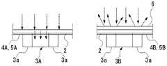
본 실시형태의 적외선 센서 (1) 는, 도 1 내지 도 4 에 나타내는 바와 같이, 절연성 필름 (2) 과, 그 절연성 필름 (2) 의 일방의 면에 서로 이간시켜 형성된 제 1 감열 소자 (3A) 및 제 2 감열 소자 (3B) 와, 절연성 필름 (2) 의 일방의 면에 형성되어 제 1 감열 소자 (3A) 에 접속된 도전성 금속막인 한 쌍의 제 1 배선막 (4A) 및 제 2 감열 소자 (3B) 에 접속된 도전성 금속막인 한 쌍의 제 2 배선막 (4B) 과, 제 2 감열 소자 (3B) 에 대향하여 절연성 필름 (2) 의 타방의 면에 형성된 적외선 반사막 (6) 과, 제 1 배선막 (4A) 및 제 2 배선막 (4B) 에 접속되고 절연성 필름 (2) 의 타방의 면에 있어서의 일단부에 형성되어 외부의 커넥터 (9) 에 끼워넣을 수 있는 제 1 단자 전극 (7A) 및 제 2 단자 전극 (7B) 과, 절연성 필름 (2) 의 일방의 면에 있어서의 일단부에 첩부된 단부 보강판 (11) 과, 절연성 필름 (2) 의 타단부에 형성된 장착용 구멍 (2b) 을 구비하고 있다.As shown in FIGS. 1 to 4, the
또, 이 적외선 센서 (1) 는, 제 1 감열 소자 (3A), 제 2 감열 소자 (3B) 및 적외선 반사막 (6) 의 영역에 대응한 센서부용 창부 (8a) 가 형성되고 절연성 필름 (2) 의 일방의 면에 상기 영역을 둘러싸고 첩부된 센서부 보강 프레임 (8) 을 구비하고 있다.Moreover, this
한 쌍의 제 1 배선막 (4A) 은, 도 1 및 도 4 의 (a) 에 나타내는 바와 같이, 그 일단부에 각각 절연성 필름 (2) 상에 형성된 한 쌍의 제 1 접착 전극 (5A) 을 갖고 있음과 함께, 타단부에 각각 절연성 필름 (2) 의 반대면 (타방의 면) 에 형성된 한 쌍의 제 1 단자 전극 (7A) 이 스루홀 (도시 생략) 을 개재하여 접속되어 있다. 또, 한 쌍의 제 2 배선막 (4B) 은, 그 일단부에 각각 절연성 필름 (2) 상에 형성된 한 쌍의 제 2 접착 전극 (5B) 을 갖고 있음과 함께, 타단부에 각각 절연성 필름 (2) 의 반대면 (타방의 면) 에 형성된 한 쌍의 제 2 단자 전극 (7B) 이 스루홀 (도시 생략) 을 개재하여 접속되어 있다.As shown in Fig. 1 and Fig. 4A, the pair of
한 쌍의 제 1 접착 전극 (5A) 은, 제 1 감열 소자 (3A) 의 주위에까지 배치되어 제 2 접착 전극 (5B) 보다 큰 면적으로 형성되어 있다. 이들 제 1 접착 전극 (5A) 은, 한 쌍의 거의 중앙에 제 1 감열 소자 (3A) 를 배치하고, 한 쌍으로 적외선 반사막 (6) 과 거의 동일한 면적으로 설정되어 있다. 즉, 제 1 접착 전극 (5A) 은, 절연성 필름 (2) 의 적외선 반사막 (6) 이 형성된 부분과 열용량이 거의 동일해지도록 설정되어 있다. 또한, 상기 제 1 접착 전극 (5A) 및 제 2 접착 전극 (5B) 에는, 각각 제 1 감열 소자 (3A) 및 제 2 감열 소자 (3B) 의 단자 전극 (3a) 이 땜납 등의 도전성 접착제로 접착된다.The pair of
상기 절연성 필름 (2) 은, 폴리이미드 수지 시트로 띠상으로 형성되고, 적외선 반사막 (6), 제 1 배선막 (4A), 제 2 배선막 (4B), 제 1 단자 전극 (7A) 및 제 2 단자 전극 (7B) 이 구리박으로 형성되어 있다. 즉, 이들은 절연성 필름 (2) 이 되는 폴리이미드 기판의 양면에, 적외선 반사막 (6), 제 1 배선막 (4A) 및 제 2 배선막 (4B) 이 되는 구리박의 전극이 패턴 형성된 양면 플렉시블 기판에 의해 제조된 것이다.The said insulating
이 절연성 필름 (2) 에는, 제 1 감열 소자 (3A) 및 제 2 감열 소자 (3B) 의 주위에 제 1 배선막 (4A) 및 제 2 배선막 (4B) 을 피해 연장되는 한 쌍의 장공부 (2a) 가 형성되어 있다. 이들 장공부 (2a) 는, 서로 대향시켜 コ 자형으로 도려낸 홈으로, 서로 간의 영역이, 제 1 감열 소자 (3A) 및 제 2 감열 소자 (3B) 가 실장됨과 함께, 제 1 배선막 (4A), 제 2 배선막 (4B) 및 적외선 반사막 (6) 이 형성되는 중앙 실장 영역이 된다. 또한, 서로 대향하는 한 쌍의 장공부 (2a) 의 단부 사이는, 제 1 배선막 (4A) 및 제 2 배선막 (4B) 이 통과하는 배선 영역이 됨과 함께, 중앙 실장 영역의 지지부로 되어 있다.The insulating
또한, 상기 적외선 반사막 (6) 은, 도 1 의 (a) 에 나타내는 바와 같이, 제 2 감열 소자 (3B) 의 바로 윗쪽에 사각 형상으로 배치되어 있고, 구리박과, 그 구리박 상에 적층된 금 도금막으로 구성되어 있다. 이 경우, 금 도금막이 구리박의 산화 방지막으로서 기능함과 함께 적외선의 반사율을 향상시킬 수 있다. 또한, 절연성 필름 (2) 의 배면에는, 제 1 단자 전극 (7A) 및 제 2 단자 전극 (7B) 을 제외하고 제 1 배선막 (4A) 및 제 2 배선막 (4B) 을 포함하는 면 전체를 덮는 폴리이미드 수지의 커버레이 (도시 생략) 가 형성되어 있다.In addition, as shown to Fig.1 (a), the said infrared reflecting
이 적외선 반사막 (6) 은, 절연성 필름 (2) 보다 높은 적외선 반사율을 갖는 재료로 형성되고, 상기 서술한 바와 같이, 구리박 상에 금 도금막이 실시되어 형성되어 있다. 또한, 금 도금막 이외에, 예를 들어 경면의 알루미늄 증착막이나 알루미늄박 등으로 형성해도 상관없다. 이 적외선 반사막 (6) 은, 제 2 감열 소자 (3B) 보다 큰 사이즈로 이것을 덮도록 형성되어 있다.This infrared reflecting
상기 제 1 감열 소자 (3A) 및 제 2 감열 소자 (3B) 는, 도 2 에 나타내는 바와 같이, 양단부에 단자 전극 (3a) 이 형성된 칩 서미스터이다. 이 서미스터로는, NTC 형, PTC 형, CTR 형 등의 서미스터가 있지만, 본 실시형태에서는, 제 1 감열 소자 (3A) 및 제 2 감열 소자 (3B) 로서, 예를 들어 NTC 형 서미스터를 채용하고 있다. 이 서미스터는, Mn-Co-Cu 계 재료, Mn-Co-Fe 계 재료 등의 서미스터 재료로 형성되어 있다. 또한, 이들 제 1 감열 소자 (3A) 및 제 2 감열 소자 (3B) 는, 각 단자 전극 (3a) 을 대응하는 제 1 접착 전극 (5A) 상 또는 제 2 접착 전극 (5B) 상에 접합시켜 절연성 필름 (2) 에 실장되어 있다.As shown in FIG. 2, the said 1st
특히, 본 실시형태에서는, 제 1 감열 소자 (3A) 및 제 2 감열 소자 (3B) 로서, Mn, Co 및 Fe 의 금속 산화물을 함유하는 세라믹 소결체, 즉 Mn-Co-Fe 계 재료로 형성된 서미스터 소자를 채용하고 있다. 또한, 이 세라믹 소결체는, 입방정 스피넬상을 주상으로 하는 결정 구조를 갖고 있는 것이 바람직하다. 특히, 세라믹 소결체로는, 입방정 스피넬상으로 이루어지는 단상의 결정 구조가 가장 바람직하다. 입방정 스피넬상을 주상으로 하는 결정 구조를 상기 세라믹 소결체에 채용하는 이유는, 이방성도 없고, 또 불순물층이 없기 때문에, 세라믹 소결체 내에서 전기 특성의 편차가 작아, 제 1 감열 소자 (3A) 와 제 2 감열 소자 (3B) 에서 고정밀의 측정이 가능해지기 때문이다. 또, 안정적인 결정 구조이기 때문에, 내환경에 대한 신뢰성도 높다.In particular, in the present embodiment, the first
상기 센서부 보강 프레임 (8) 및 단부 보강판 (11) 은, 예를 들어 유리 에폭시 기판 등의 절연성을 갖는 경질인 수지 기판 등으로 형성되어 있다. 센서부 보강 프레임 (8) 은, 도 1 의 (b) 에 나타내는 바와 같이, 센서부 (3) 에 대응한 사각형상의 센서부용 창부 (8a) 가 형성되어 있다. 이 센서부용 창부 (8a) 는, 한 쌍의 장공부 (2a) 의 내측에 형성되고, 제 1 접착 전극 (5A) 및 제 2 접착 전극 (5B) 을 둘러싸도록 형성되어 있다.The said sensor
또, 센서부 보강 프레임 (8) 에는, 도 4 의 (b) 에 나타내는 바와 같이, 센서부용 창부 (8a) 를 막는 시일재 (10) 가 배면에 첩부되어 있다. 이 시일재 (10) 는, 외부로부터의 적외선을 반사 가능한 것이 바람직하고, 상기 적외선 반사막 (6) 과 동일한 막이나 알루미늄박 등을 적용할 수 있다. 상기 단부 보강판 (11) 은, 절연성 필름 (2) 의 일단부의 형상에 대응하여 사각형상으로 형성되어 있다.Moreover, as shown in FIG.4 (b), the sealing
이 적외선 센서 (1) 는, 도 3 에 나타내는 바와 같이, 회로 기판 (104) 상의 커넥터 (9) 에 일단부, 즉 제 1 단자 전극 (7A) 및 제 2 단자 전극 (7B) 과 단부 보강판 (11) 을 갖는 단부를 꽂아 넣음과 함께, 타단부를 커넥터 (9) 의 상방에 배치된 하우징이나 히트 싱크 등의 외부 부재 (H) 에 장착용 구멍 (2b) 을 이용하여 나사 (N) 로 고정시켜 실장된다. 또한, 절연성 필름 (2) 의 타단부는 유연하기 때문에, 절곡하거나 만곡시킴으로써, 외부 부재 (H) 의 장착면의 방향에 대응하여 장착할 수 있다. 또, 이 때, 절연성 필름 (2) 의 타방의 면, 즉 적외선 반사막 (6) 이 형성된 면을, 전해 콘덴서나 스위칭 소자 등의 측정 대상물 (S) 을 향하여 적외선 센서 (1) 가 설치된다.As shown in FIG. 3, the
이와 같이 본 실시형태의 적외선 센서 (1) 에서는, 절연성 필름 (2) 의 타방의 면에 있어서의 일단부에 형성되어 외부의 커넥터 (9) 에 끼워넣을 수 있는 제 1 단자 전극 (7A) 및 제 2 단자 전극 (7B) 과, 절연성 필름 (2) 의 일방의 면에 있어서의 일단부에 첩부된 단부 보강판 (11) 과, 절연성 필름 (2) 의 타단부에 형성된 장착용 구멍 (2b) 을 구비하고 있기 때문에, 단부 보강판 (11) 에 의해 고강성이 된 일단부의 단자 전극 (7A, 7B) 을 커넥터 (9) 에 끼워 넣음으로써 용이하게 회로 기판 (104) 에 고정 및 전기적 접속을 할 수 있음과 함께, 커넥터 (9) 로부터 떨어진 하우징이나 히트 싱크 등의 외부 부재 (H) 에 장착용 구멍 (2b) 을 이용하여 절연성 필름 (2) 의 타단부를 나사 고정 등에 의해 고정시킬 수 있다.As described above, in the
이로써, 절연성 필름 (2) 의 양단부가 고정되어 팽팽한 설치 상태가 되어, 전체가 안정적으로 지지됨으로써, 제 1 감열 소자 (3A), 제 2 감열 소자 (3B) 및 적외선 반사막 (6) 을 포함하는 센서부 (3) 가 커넥터 (9) 로부터 떨어져 배치되어 있더라도, 진동에 의해 센서부 (3) 의 시야각이 흔들리거나, 진동 잡음이 더해지거나 하는 것을 억제할 수 있다. 즉, 도 3 의 (b) 에 나타내는 바와 같이, 측정 대상물 (S) 에서 온도를 측정하고자 하는 부분 (S1) 이 회로 기판 (104) 으로부터 떨어진 위치여도, 그 부분 (S1) 에 센서부 (3) 를 대향 상태로 안정적으로 배치하는 것이 용이해진다.Thereby, the both ends of the insulating
또, 절연성 필름 (2) 이 유연하기 때문에, 장착용 구멍 (2b) 에 의한 타단부의 장착 위치를 커넥터 (9) 바로 윗쪽으로부터 어긋나게 할 수도 있고, 센서부 (3) 의 기울기를 바꿔 적외선의 검출 방향을 임의로 변경할 수도 있다. 따라서, 회로 기판 (104) 상에 리플로우로 실장한 커넥터 (9) 에 일단부를 꽂아 넣음과 함께 타단부를 장착용 구멍 (2b) 을 이용하여 고정시키는 것만으로 용이하게 장착할 수 있고, 좁은 설치 스페이스에서도 실장할 수 있어, 고밀도화에도 적합하고, 또한 회로 기판 (104) 으로부터 떨어진 위치의 온도도 고정밀도로 검출할 수 있게 된다.Moreover, since the insulating
또, 절연성 필름 (2) 의 일방의 면에 제 1 감열 소자 (3A), 제 2 감열 소자 (3B) 및 적외선 반사막 (6) 의 영역을 둘러싸고 첩부된 센서부 보강 프레임 (8) 을 구비하고 있기 때문에, 센서부 보강 프레임 (8) 에 의해 센서부 (3) 가 되는 상기 영역 주위의 강성을 높여, 팽팽하게 설치할 때에 제 1 감열 소자 (3A) 및 제 2 감열 소자 (3B) 에 가해지는 응력을 억제할 수 있다. 또한, 센서부 보강 프레임 (8) 내는, 센서부 (3) 에 공간을 형성하도록 도려내어져 센서부용 창부 (8a) 로 되어 있기 때문에, 센서부 보강 프레임 (8) 이 제 1 감열 소자 (3A) 및 제 2 감열 소자 (3B) 의 실장의 방해가 되지 않음과 함께, 센서부 (3) 에 대해 센서부 보강 프레임 (8) 으로부터의 열 전도에 의한 영향이 억제된다.Moreover, the one side of the insulating
또한, 센서부용 창부 (8a) 를 막는 시일재 (10) 가 센서부 보강 프레임 (8) 에 첩부되어 있기 때문에, 시일재 (10) 에 의해 공간을 비운 상태에서 센서부 (3) 를 커버할 수 있어, 배면으로부터의 공기 대류나 적외선의 영향을 경감시킬 수 있다.Moreover, since the sealing
또, 절연성 필름 (2) 에, 제 1 감열 소자 (3A) 및 제 2 감열 소자 (3B) 의 주위에 제 1 배선막 (4A) 및 제 2 배선막 (4B) 을 피해 연장되는 장공부 (2a) 가 형성되어 있기 때문에, 제 1 감열 소자 (3A) 상의 적외선 흡수 영역으로부터 주위로의 열의 전도가 장공부 (2a) 에 의해 차단되어, 측정 대상물 (S) 로부터의 복사열을 열 격리하여 효율적으로 축적할 수 있다. 또, 측정 대상물 (S) 로부터의 복사열에 의해 온도 분포가 흐트러지지 않도록, 주변 장치로부터의 열의 영향을 받은 부분으로부터의 열 전도를 장공부 (2a) 에 의해 차단하여 영향을 억제할 수 있다.Moreover, the
또, 제 1 배선막 (4A) 이 제 1 감열 소자 (3A) 의 주위에까지 배치되어 제 2 배선막 (4B) 보다 큰 면적으로 형성되어 있기 때문에, 절연성 필름 (2) 의 적외선을 흡수한 부분으로부터의 열 수집을 개선함과 함께, 절연성 필름 (2) 의 적외선 반사막 (6) 이 형성된 부분과 열용량이 가까워지므로, 변동 오차를 작게 할 수 있다.Moreover, since the
다음으로, 본 발명에 관련된 적외선 센서의 제 2 실시형태에 대하여, 도 5 및 도 6 을 참조하여 이하에 설명한다. 또한, 이하의 실시형태의 설명에 있어서, 상기 실시형태에 있어서 설명한 동일한 구성 요소에는 동일한 부호를 부여하고, 그 설명은 생략한다.Next, 2nd Embodiment of the infrared sensor which concerns on this invention is described below with reference to FIG. In addition, in description of the following embodiment, the same code | symbol is attached | subjected to the same component demonstrated in the said embodiment, and the description is abbreviate | omitted.
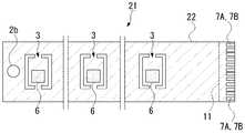
제 2 실시형태와 제 1 실시형태의 상이한 점은, 제 1 실시형태에서는, 절연성 필름 (2) 에 제 1 감열 소자 (3A) 와 제 2 감열 소자 (3B) 를 갖는 센서부 (3) 가 하나만 형성되어 있는 데에 반해, 제 2 실시형태의 적외선 센서 (21) 는, 도 6 에 나타내는 바와 같이, 적어도 제 1 감열 소자 (3A), 제 2 감열 소자 (3B) 및 적외선 반사막 (6) 으로 이루어지는 센서부 (3) 가 절연성 필름 (22) 에 복수 형성되고, 이들에 대응하는 단자 전극 (7A, 7B) 이 모두 절연성 필름 (22) 의 일단부에 형성되어 있는 점이다.The difference between the second embodiment and the first embodiment is that in the first embodiment, only one
즉, 제 2 실시형태에서는, 절연성 필름 (22) 이 제 1 실시형태보다 길어, 서로 연장 방향으로 간격을 두고 복수 (도 6 에서는 3 개) 의 센서부 (3) 가 형성되어 있다. 이들 센서부 (3) 는, 각각 제 1 배선막 및 제 2 배선막을 개재하여 일단부의 단자 전극 (7A, 7B) 에 접속되어 있다.That is, in 2nd Embodiment, the insulating
종래, 복수 지점의 온도를 검출하기 위해, 예를 들어 도 5 에 나타내는 바와 같이, 복수의 온도 센서 (105) 와 이들에 접속된 복수의 도전선 (106) 을 각 지점에 배치 형성할 필요가 있어, 도전선 (106) 의 처리나 장착 공정이 번거로워짐과 함께, 내진성을 확보하기 위해 도전선 (106) 으로서 굵은 선재가 필요하다는 문제가 있었다.Conventionally, in order to detect the temperature of a several point, as shown, for example in FIG. 5, it is necessary to arrange | position and form the some
이에 반해, 제 2 실시형태의 적외선 센서 (21) 에서는, 센서부 (3) 가 절연성 필름 (22) 에 복수 형성되고, 이들에 대응하는 단자 전극 (7A, 7B) 이 모두 절연성 필름 (22) 의 일단부에 형성되어 있기 때문에, 일단부를 커넥터에 꽂아 넣어 고정시킴과 함께 타단부를 외부 부재 등에 고정시킴으로써, 복수의 센서부 (3) 를 배치할 수 있어, 복수 지점의 온도를 검출할 수 있게 된다. 또, 복수의 센서부 (3) 가 하나의 절연성 필름 (22) 에 일체로 형성되어 있기 때문에, 복수의 온도 센서 (105) 와 복수의 도전선 (106) 을 배치 형성할 필요가 없어, 조립 공정도 간략화할 수 있음과 함께, 내진성도 확보할 수 있다.On the other hand, in the
따라서, 이 적외선 센서 (21) 는, 예를 들어 Li 이온 등의 배터리 유닛이나 에어컨디셔너의 프론트 윈도우 등에 있어서의 복수 지점의 온도 검출에 바람직하다. 또한, 상기 제 2 실시형태에서는, 장착용 구멍 (2b) 이 절연성 필름 (22) 의 타단부에만 형성되어 있지만, 긴 절연성 필름 (22) 의 도중에도 하나 또는 복수의 장착용 구멍 (2b) 을 형성하여 외부 부재 등에 나사 고정 등으로 고정시켜도 상관없다.Therefore, this
또한, 본 발명의 기술 범위는 상기 각 실시형태에 한정되지 않고, 본 발명의 취지를 일탈하지 않는 범위에서 여러 가지의 변경을 가할 수 있다.In addition, the technical scope of this invention is not limited to each said embodiment, A various change can be added in the range which does not deviate from the meaning of this invention.
예를 들어, 상기 각 실시형태에서는, 제 1 감열 소자가 적외선을 직접 흡수한 절연성 필름으로부터 전도되는 열을 검출하고 있지만, 제 1 감열 소자의 바로 윗쪽으로 절연성 필름 상에 적외선 흡수막을 형성해도 상관없다. 이 경우, 제 1 감열 소자에 있어서의 적외선 흡수 효과가 더욱 향상되어, 제 1 감열 소자와 제 2 감열 소자의 보다 양호한 온도차분을 얻을 수 있다. 즉, 이 적외선 흡수막에 의해 측정 대상물로부터의 복사에 의한 적외선을 흡수하도록 하여, 적외선을 흡수하여 발열된 적외선 흡수막으로부터 절연성 필름을 개재한 열 전도에 의해, 바로 아래의 제 1 감열 소자의 온도가 변화되도록 해도 된다.For example, in each said embodiment, although the 1st thermosensitive element detects the heat | fever conducted from the insulating film which directly absorbed the infrared ray, you may form an infrared absorbing film on an insulating film directly above a 1st thermosensitive element. . In this case, the infrared absorption effect in a 1st thermosensitive element further improves, and the temperature difference of a 1st thermosensitive element and a 2nd thermosensitive element can be obtained more. That is, the infrared absorbing film absorbs the infrared rays by the radiation from the measurement object, and the temperature of the first heat-sensitive element immediately below by thermal conduction via the insulating film from the infrared absorbing film that absorbs infrared rays and generates heat. May be changed.
이 적외선 흡수막은, 절연성 필름보다 높은 적외선 흡수율을 갖는 재료로 형성되며, 예를 들어, 카본 블랙 등의 적외선 흡수 재료를 포함하는 필름이나 적외선 흡수성 유리막 (이산화규소를 71 % 함유하는 붕규산 유리막 등) 으로 형성되어 있는 것 등을 채용할 수 있다. 특히, 적외선 흡수막은, 안티몬 도프 산화주석 (ATO) 막인 것이 바람직하다. 이 ATO 막은, 카본 블랙 등에 비해 적외선의 흡수율이 양호함과 함께 내광성이 우수하다. 또, ATO 막은, 자외선으로 경화시키기 때문에, 접착 강도가 강하여, 카본 블랙 등에 비해 잘 박리되지 않는다. 또한, 이 적외선 흡수막은, 제 1 감열 소자보다 큰 사이즈로 이것을 덮도록 형성하는 것이 바람직하다.The infrared absorbing film is formed of a material having a higher infrared absorptivity than the insulating film, and is, for example, a film containing an infrared absorbing material such as carbon black or an infrared absorbing glass film (such as a borosilicate glass film containing 71% silicon dioxide). What is formed, etc. can be employ | adopted. In particular, the infrared absorbing film is preferably an antimony-doped tin oxide (ATO) film. This ATO film is excellent in light resistance while being excellent in the absorption rate of infrared rays compared with carbon black etc. Moreover, since ATO film | membrane hardens with an ultraviolet-ray, adhesive strength is strong and it does not peel easily compared with carbon black etc. Moreover, it is preferable to form this infrared absorption film so that it may cover this in size larger than a 1st heat sensitive element.
또, 칩 서미스터의 제 1 감열 소자 및 제 2 감열 소자를 채용하고 있지만, 박막 서미스터로 형성된 제 1 감열 소자 및 제 2 감열 소자를 채용해도 상관없다. 또한, 감열 소자로는, 상기 서술한 바와 같이 박막 서미스터나 칩 서미스터가 사용되지만, 서미스터 이외에 초전 소자 등도 채용할 수 있다. 또한, 수지 필름에 상기 센서부뿐만 아니라, 그 센서부에 접속된 센서 제어용 검출 회로인 회로부도 일체로 형성해도 상관없다.Moreover, although the 1st thermosensitive element and 2nd thermosensitive element of a chip thermistor are employ | adopted, you may employ | adopt the 1st thermosensitive element and 2nd thermosensitive element formed with the thin film thermistor. As the thermal element, a thin film thermistor or a chip thermistor is used as described above, but a pyroelectric element or the like can be used in addition to the thermistor. Moreover, you may integrally form not only the said sensor part but the circuit part which is a detection circuit for sensor control connected to the sensor part in the resin film.
1, 21…적외선 센서, 2, 22…절연성 필름, 2a…장공부, 2b…장착용 구멍, 3…센서부, 3A…제 1 감열 소자, 3B…제 2 감열 소자, 4A…제 1 배선막, 4B…제 2 배선막, 5A…제 1 단자 전극, 5B…제 2 단자 전극, 6…적외선 반사막, 7A…제 1 단자 전극, 7B…제 2 단자 전극, 8…센서부 보강 프레임, 8a…센서부용 창부, 9…커넥터, 10…시일재, 11…단부 보강판, H…외부 부재1, 21... Infrared sensor, 2, 22... Insulating film, 2a... Long, 2b... Mounting hole, 3... Sensor unit, 3A... First thermal element, 3B... Second thermal element, 4A... First wiring film, 4B... Second wiring film, 5A... First terminal electrode, 5B... Second terminal electrode, 6... Infrared reflecting film, 7A... First terminal electrode, 7B... Second terminal electrode, 8.. Sensor unit reinforcement frame, 8a... Sensor window, 9.. Connector, 10.. Sealant, 11... End gusset, H... External member
Claims (5)
Translated fromKorean상기 제 1 감열 소자, 상기 제 2 감열 소자 및 상기 적외선 반사막의 영역에 대응한 센서부용 창부가 형성되고 상기 절연성 필름의 일방의 면에 상기 영역을 둘러싸고 첩부된 센서부 보강 프레임을 구비하고 있는 것을 특징으로 하는 적외선 센서.The method of claim 1,
The sensor part window part corresponding to the area | region of the said 1st thermal element, the said 2nd thermal element, and the said infrared reflecting film is formed, and is provided with the sensor part reinforcement frame enclosed and affixed on the one surface of the said insulating film. Infrared sensor.
적어도 상기 제 1 감열 소자, 상기 제 2 감열 소자 및 상기 적외선 반사막으로 이루어지는 센서부가 상기 절연성 필름에 복수 형성되고, 이들에 대응하는 상기 단자 전극이 모두 상기 절연성 필름의 일단부에 형성되어 있는 것을 특징으로 하는 적외선 센서.The method of claim 1,
A plurality of sensor portions comprising at least the first heat sensitive element, the second heat sensitive element, and the infrared reflecting film are formed in the insulating film, and the terminal electrodes corresponding thereto are all formed at one end of the insulating film. Infrared sensor.
상기 센서부용 창부를 막는 시일재가 상기 센서부 보강 프레임에 첩부되어 있는 것을 특징으로 하는 적외선 센서.3. The method of claim 2,
The sealing material which blocks the said window part for said sensor parts is affixed on the said sensor part reinforcement frame, The infrared sensor characterized by the above-mentioned.
상기 제 1 배선막이 상기 제 1 감열 소자의 주위에까지 배치되어 상기 제 2 배선막보다 큰 면적으로 형성되어 있는 것을 특징으로 하는 적외선 센서.
The method of claim 1,
An infrared sensor, characterized in that the first wiring film is arranged even around the first heat sensitive element and is formed with a larger area than the second wiring film.
Applications Claiming Priority (3)
| Application Number | Priority Date | Filing Date | Title |
|---|---|---|---|
| JP2011076768AJP5754626B2 (en) | 2011-03-30 | 2011-03-30 | Infrared sensor |
| JPJP-P-2011-076768 | 2011-03-30 | ||
| PCT/JP2012/001976WO2012132342A1 (en) | 2011-03-30 | 2012-03-22 | Infrared sensor |
Publications (1)
| Publication Number | Publication Date |
|---|---|
| KR20140012697Atrue KR20140012697A (en) | 2014-02-03 |
Family
ID=46930124
Family Applications (1)
| Application Number | Title | Priority Date | Filing Date |
|---|---|---|---|
| KR1020137025541ACeasedKR20140012697A (en) | 2011-03-30 | 2012-03-22 | Infrared sensor |
Country Status (7)
| Country | Link |
|---|---|
| US (1) | US9435691B2 (en) |
| EP (1) | EP2693177B1 (en) |
| JP (1) | JP5754626B2 (en) |
| KR (1) | KR20140012697A (en) |
| CN (1) | CN103370606B (en) |
| TW (1) | TWI536000B (en) |
| WO (1) | WO2012132342A1 (en) |
Families Citing this family (8)
| Publication number | Priority date | Publication date | Assignee | Title |
|---|---|---|---|---|
| JP5736906B2 (en)* | 2011-03-30 | 2015-06-17 | 三菱マテリアル株式会社 | Infrared sensor |
| JP5615338B2 (en)* | 2012-11-08 | 2014-10-29 | 三菱電機株式会社 | Capacitor deterioration diagnosis device, inverter device, and home appliance |
| EP2736100B1 (en)* | 2012-11-22 | 2017-06-21 | Samsung SDI Co., Ltd. | Electronic unit with temperature measuring device for a battery system |
| CN103344328B (en)* | 2013-07-15 | 2015-01-07 | 河北大学 | A Multilayer Structure Lateral Pyroelectric Photodetector |
| JP5488751B1 (en)* | 2013-08-30 | 2014-05-14 | 富士ゼロックス株式会社 | Temperature sensor, fixing device, and image forming apparatus |
| US10057964B2 (en) | 2015-07-02 | 2018-08-21 | Hayward Industries, Inc. | Lighting system for an environment and a control module for use therein |
| US9925497B2 (en)* | 2015-07-13 | 2018-03-27 | Hamilton Sunstrand Corporation | Condition monitoring for an air separation module |
| CN110702234A (en)* | 2019-11-05 | 2020-01-17 | 广东电网有限责任公司 | GIS infrared temperature measuring device and temperature compensation calibration method thereof |
Family Cites Families (29)
| Publication number | Priority date | Publication date | Assignee | Title |
|---|---|---|---|---|
| JPS61117420A (en)* | 1984-11-14 | 1986-06-04 | Sumitomo Bakelite Co Ltd | infrared detector |
| JPH06186082A (en)* | 1992-12-22 | 1994-07-08 | Murata Mfg Co Ltd | Infrared sensor device |
| JP3007244B2 (en)* | 1993-07-22 | 2000-02-07 | シャープ株式会社 | Radiation temperature detector |
| JP3327668B2 (en) | 1994-03-24 | 2002-09-24 | 石塚電子株式会社 | Infrared detector |
| JP2987543B2 (en)* | 1994-05-26 | 1999-12-06 | 松下電工株式会社 | Thermistor thin film element and human body heat detector using the same |
| US6489614B1 (en)* | 1999-09-16 | 2002-12-03 | Sharp Kabushiki Kaisha | Thermal-type infrared radiation detector cell and image capture device incorporating the same |
| JP3409848B2 (en)* | 2000-08-29 | 2003-05-26 | 日本電気株式会社 | Thermal infrared detector |
| JP4628540B2 (en) | 2000-11-20 | 2011-02-09 | 石塚電子株式会社 | Infrared temperature sensor |
| JP2003194630A (en) | 2001-12-27 | 2003-07-09 | Ishizuka Electronics Corp | Noncontact temperature sensor and sensing circuit for noncontact temperature sensor |
| US7157709B2 (en)* | 2002-06-25 | 2007-01-02 | Matsushita Electric Works, Ltd. | Infrared sensor package |
| JP2004061283A (en) | 2002-07-29 | 2004-02-26 | Ishizuka Electronics Corp | Infrared sensor, and determining device of size and surface temperature of object, using sensor |
| WO2005024366A1 (en)* | 2003-09-04 | 2005-03-17 | Quartex | Temperature measuring apparatus |
| JP2007509315A (en)* | 2003-10-09 | 2007-04-12 | オカス コーポレーション | Two-layer bolometer-type infrared sensor and method for manufacturing the same |
| JP4315832B2 (en)* | 2004-02-17 | 2009-08-19 | 三菱電機株式会社 | Thermal infrared sensor element and thermal infrared sensor array |
| JP2005268404A (en)* | 2004-03-17 | 2005-09-29 | Sanyo Electric Co Ltd | Circuit module |
| JP4385255B2 (en)* | 2004-06-10 | 2009-12-16 | 日本電気株式会社 | Bolometer type infrared detector and method for reducing afterimage |
| JP5201780B2 (en)* | 2004-06-14 | 2013-06-05 | ルネサスエレクトロニクス株式会社 | Photodetector and photodetection device |
| JP2006133131A (en)* | 2004-11-08 | 2006-05-25 | Matsushita Electric Works Ltd | Sensor system |
| JP2006228768A (en)* | 2005-02-15 | 2006-08-31 | Funai Electric Co Ltd | Connection structure between cable and wiring board, dvd drive, and television having the same |
| JP2010038782A (en)* | 2008-08-06 | 2010-02-18 | Ricoh Co Ltd | Thermopile evaluating device |
| DE112009002170B4 (en)* | 2008-09-09 | 2015-10-22 | Taiwan Semiconductor Manufacturing Co., Ltd. | Planar thermopile infrared sensor |
| KR101199904B1 (en)* | 2008-09-25 | 2012-11-09 | 파나소닉 주식회사 | Infrared sensor |
| JP5218188B2 (en)* | 2009-03-19 | 2013-06-26 | 三菱マテリアル株式会社 | Temperature sensor |
| JP5219923B2 (en)* | 2009-05-25 | 2013-06-26 | 三菱電機株式会社 | Infrared detector and cooking device |
| JP2011013213A (en)* | 2009-06-02 | 2011-01-20 | Mitsubishi Materials Corp | Infrared sensor |
| JP5640529B2 (en) | 2009-10-17 | 2014-12-17 | 三菱マテリアル株式会社 | Infrared sensor and circuit board having the same |
| JP5832007B2 (en) | 2009-12-25 | 2015-12-16 | 三菱マテリアル株式会社 | Infrared sensor and manufacturing method thereof |
| CN101871818B (en)* | 2010-06-25 | 2012-05-23 | 清华大学 | Infrared detector |
| JP5662225B2 (en)* | 2011-03-31 | 2015-01-28 | 旭化成エレクトロニクス株式会社 | Infrared sensor |
- 2011
- 2011-03-30JPJP2011076768Apatent/JP5754626B2/ennot_activeExpired - Fee Related
- 2012
- 2012-03-22USUS14/003,728patent/US9435691B2/ennot_activeExpired - Fee Related
- 2012-03-22KRKR1020137025541Apatent/KR20140012697A/ennot_activeCeased
- 2012-03-22WOPCT/JP2012/001976patent/WO2012132342A1/enactiveApplication Filing
- 2012-03-22EPEP12763778.3Apatent/EP2693177B1/ennot_activeNot-in-force
- 2012-03-22CNCN201280008135.1Apatent/CN103370606B/ennot_activeExpired - Fee Related
- 2012-03-26TWTW101110384Apatent/TWI536000B/ennot_activeIP Right Cessation
Also Published As
| Publication number | Publication date |
|---|---|
| EP2693177B1 (en) | 2018-11-07 |
| TWI536000B (en) | 2016-06-01 |
| JP2012211791A (en) | 2012-11-01 |
| CN103370606A (en) | 2013-10-23 |
| US9435691B2 (en) | 2016-09-06 |
| TW201303271A (en) | 2013-01-16 |
| JP5754626B2 (en) | 2015-07-29 |
| CN103370606B (en) | 2015-05-13 |
| WO2012132342A1 (en) | 2012-10-04 |
| EP2693177A1 (en) | 2014-02-05 |
| EP2693177A4 (en) | 2014-09-24 |
| US20140010262A1 (en) | 2014-01-09 |
Similar Documents
| Publication | Publication Date | Title |
|---|---|---|
| KR101729370B1 (en) | Infrared sensor | |
| KR101639838B1 (en) | Infrared sensor and a circuit board therewith | |
| KR20140012697A (en) | Infrared sensor | |
| JP5832007B2 (en) | Infrared sensor and manufacturing method thereof | |
| KR101972196B1 (en) | Infrared sensor | |
| JP2011013213A (en) | Infrared sensor | |
| KR101972197B1 (en) | Infrared sensor and infrared sensor device | |
| JP5741830B2 (en) | Infrared sensor device | |
| JP5741924B2 (en) | Infrared sensor | |
| JP5720999B2 (en) | Infrared sensor and circuit board having the same | |
| JP5569268B2 (en) | Battery temperature sensor device |
Legal Events
| Date | Code | Title | Description |
|---|---|---|---|
| PA0105 | International application | Patent event date:20130927 Patent event code:PA01051R01D Comment text:International Patent Application | |
| PG1501 | Laying open of application | ||
| A201 | Request for examination | ||
| A302 | Request for accelerated examination | ||
| AMND | Amendment | ||
| PA0201 | Request for examination | Patent event code:PA02012R01D Patent event date:20170106 Comment text:Request for Examination of Application | |
| PA0302 | Request for accelerated examination | Patent event date:20170106 Patent event code:PA03022R01D Comment text:Request for Accelerated Examination | |
| E902 | Notification of reason for refusal | ||
| PE0902 | Notice of grounds for rejection | Comment text:Notification of reason for refusal Patent event date:20170322 Patent event code:PE09021S01D | |
| E902 | Notification of reason for refusal | ||
| PE0902 | Notice of grounds for rejection | Comment text:Notification of reason for refusal Patent event date:20170728 Patent event code:PE09021S01D | |
| AMND | Amendment | ||
| E601 | Decision to refuse application | ||
| PE0601 | Decision on rejection of patent | Patent event date:20171228 Comment text:Decision to Refuse Application Patent event code:PE06012S01D Patent event date:20170728 Comment text:Notification of reason for refusal Patent event code:PE06011S01I Patent event date:20170322 Comment text:Notification of reason for refusal Patent event code:PE06011S01I | |
| AMND | Amendment | ||
| PX0901 | Re-examination | Patent event code:PX09011S01I Patent event date:20171228 Comment text:Decision to Refuse Application Patent event code:PX09012R01I Patent event date:20170928 Comment text:Amendment to Specification, etc. Patent event code:PX09012R01I Patent event date:20170106 Comment text:Amendment to Specification, etc. | |
| PX0601 | Decision of rejection after re-examination | Comment text:Decision to Refuse Application Patent event code:PX06014S01D Patent event date:20180313 Comment text:Amendment to Specification, etc. Patent event code:PX06012R01I Patent event date:20180226 Comment text:Decision to Refuse Application Patent event code:PX06011S01I Patent event date:20171228 Comment text:Amendment to Specification, etc. Patent event code:PX06012R01I Patent event date:20170928 Comment text:Notification of reason for refusal Patent event code:PX06013S01I Patent event date:20170728 Comment text:Notification of reason for refusal Patent event code:PX06013S01I Patent event date:20170322 Comment text:Amendment to Specification, etc. Patent event code:PX06012R01I Patent event date:20170106 |