KR20140011246A - Document, image forming apparatus, cover plate, and image reading apparatus - Google Patents
Document, image forming apparatus, cover plate, and image reading apparatusDownload PDFInfo
- Publication number
- KR20140011246A KR20140011246AKR1020130036256AKR20130036256AKR20140011246AKR 20140011246 AKR20140011246 AKR 20140011246AKR 1020130036256 AKR1020130036256 AKR 1020130036256AKR 20130036256 AKR20130036256 AKR 20130036256AKR 20140011246 AKR20140011246 AKR 20140011246A
- Authority
- KR
- South Korea
- Prior art keywords
- image
- original
- reading
- paper
- document
- Prior art date
- Legal status (The legal status is an assumption and is not a legal conclusion. Google has not performed a legal analysis and makes no representation as to the accuracy of the status listed.)
- Granted
Links
Images


Classifications
- G—PHYSICS
- G03—PHOTOGRAPHY; CINEMATOGRAPHY; ANALOGOUS TECHNIQUES USING WAVES OTHER THAN OPTICAL WAVES; ELECTROGRAPHY; HOLOGRAPHY
- G03G—ELECTROGRAPHY; ELECTROPHOTOGRAPHY; MAGNETOGRAPHY
- G03G21/00—Arrangements not provided for by groups G03G13/00 - G03G19/00, e.g. cleaning, elimination of residual charge
- H—ELECTRICITY
- H04—ELECTRIC COMMUNICATION TECHNIQUE
- H04N—PICTORIAL COMMUNICATION, e.g. TELEVISION
- H04N1/00—Scanning, transmission or reproduction of documents or the like, e.g. facsimile transmission; Details thereof
- H04N1/00681—Detecting the presence, position or size of a sheet or correcting its position before scanning
- H04N1/00684—Object of the detection
- H04N1/00702—Position
- G—PHYSICS
- G03—PHOTOGRAPHY; CINEMATOGRAPHY; ANALOGOUS TECHNIQUES USING WAVES OTHER THAN OPTICAL WAVES; ELECTROGRAPHY; HOLOGRAPHY
- G03G—ELECTROGRAPHY; ELECTROPHOTOGRAPHY; MAGNETOGRAPHY
- G03G15/00—Apparatus for electrographic processes using a charge pattern
- G03G15/60—Apparatus which relate to the handling of originals
- G03G15/602—Apparatus which relate to the handling of originals for transporting
- G—PHYSICS
- G03—PHOTOGRAPHY; CINEMATOGRAPHY; ANALOGOUS TECHNIQUES USING WAVES OTHER THAN OPTICAL WAVES; ELECTROGRAPHY; HOLOGRAPHY
- G03G—ELECTROGRAPHY; ELECTROPHOTOGRAPHY; MAGNETOGRAPHY
- G03G15/00—Apparatus for electrographic processes using a charge pattern
- G03G15/60—Apparatus which relate to the handling of originals
- G03G15/607—Apparatus which relate to the handling of originals for detecting size, presence or position of original
- H—ELECTRICITY
- H04—ELECTRIC COMMUNICATION TECHNIQUE
- H04N—PICTORIAL COMMUNICATION, e.g. TELEVISION
- H04N1/00—Scanning, transmission or reproduction of documents or the like, e.g. facsimile transmission; Details thereof
- H—ELECTRICITY
- H04—ELECTRIC COMMUNICATION TECHNIQUE
- H04N—PICTORIAL COMMUNICATION, e.g. TELEVISION
- H04N1/00—Scanning, transmission or reproduction of documents or the like, e.g. facsimile transmission; Details thereof
- H04N1/00795—Reading arrangements
- H04N1/00798—Circuits or arrangements for the control thereof, e.g. using a programmed control device or according to a measured quantity
- H04N1/00816—Determining the reading area, e.g. eliminating reading of margins
- H—ELECTRICITY
- H04—ELECTRIC COMMUNICATION TECHNIQUE
- H04N—PICTORIAL COMMUNICATION, e.g. TELEVISION
- H04N1/00—Scanning, transmission or reproduction of documents or the like, e.g. facsimile transmission; Details thereof
- H04N1/04—Scanning arrangements, i.e. arrangements for the displacement of active reading or reproducing elements relative to the original or reproducing medium, or vice versa
- H04N1/047—Detection, control or error compensation of scanning velocity or position
- H—ELECTRICITY
- H04—ELECTRIC COMMUNICATION TECHNIQUE
- H04N—PICTORIAL COMMUNICATION, e.g. TELEVISION
- H04N2201/00—Indexing scheme relating to scanning, transmission or reproduction of documents or the like, and to details thereof
- H04N2201/0077—Types of the still picture apparatus
- H04N2201/0091—Digital copier; digital 'photocopier'
- H—ELECTRICITY
- H04—ELECTRIC COMMUNICATION TECHNIQUE
- H04N—PICTORIAL COMMUNICATION, e.g. TELEVISION
- H04N2201/00—Indexing scheme relating to scanning, transmission or reproduction of documents or the like, and to details thereof
- H04N2201/04—Scanning arrangements
- H04N2201/0402—Arrangements not specific to a particular one of the scanning methods covered by groups H04N1/04 - H04N1/207
- H04N2201/0414—Scanning an image in a series of overlapping zones
- H—ELECTRICITY
- H04—ELECTRIC COMMUNICATION TECHNIQUE
- H04N—PICTORIAL COMMUNICATION, e.g. TELEVISION
- H04N2201/00—Indexing scheme relating to scanning, transmission or reproduction of documents or the like, and to details thereof
- H04N2201/04—Scanning arrangements
- H04N2201/047—Detection, control or error compensation of scanning velocity or position
- H04N2201/04701—Detection of scanning velocity or position
- H04N2201/04703—Detection of scanning velocity or position using the scanning elements as detectors, e.g. by performing a prescan
- H—ELECTRICITY
- H04—ELECTRIC COMMUNICATION TECHNIQUE
- H04N—PICTORIAL COMMUNICATION, e.g. TELEVISION
- H04N2201/00—Indexing scheme relating to scanning, transmission or reproduction of documents or the like, and to details thereof
- H04N2201/04—Scanning arrangements
- H04N2201/047—Detection, control or error compensation of scanning velocity or position
- H04N2201/04701—Detection of scanning velocity or position
- H04N2201/04715—Detection of scanning velocity or position by detecting marks or the like, e.g. slits
- H04N2201/04717—Detection of scanning velocity or position by detecting marks or the like, e.g. slits on the scanned sheet, e.g. a reference sheet
Landscapes
- Engineering & Computer Science (AREA)
- Multimedia (AREA)
- Signal Processing (AREA)
- Physics & Mathematics (AREA)
- General Physics & Mathematics (AREA)
- Facsimile Scanning Arrangements (AREA)
- Control Or Security For Electrophotography (AREA)
- Facsimiles In General (AREA)
- Holders For Sensitive Materials And Originals (AREA)
- Image Input (AREA)
Abstract
Translated fromKoreanDescription
Translated fromKorean본 발명은, 원고, 화상 형성 장치, 덮개판, 및 화상 판독 장치에 관한 것이다.The present invention relates to a document, an image forming apparatus, a cover plate, and an image reading apparatus.
특허문헌 1에는, 원고 판독면측의 면 위에 모양이 기재된 원고 누름판을 사용하여, 원고 누름판으로 원고를 덮어서 판독을 행할 때에는, 원고 누름판의 모양이 원고에 의해 가려진 부분을 인식함으로써, 원고의 사이즈나 위치, 기울기를 검출하는 방법이 개시되어 있다.Patent Document 1 uses a document holding plate whose shape is written on the surface of the document reading surface side, and when reading the document by covering the document with the document holding plate, the shape of the document holding plate is recognized by recognizing the portion covered by the document. , A method of detecting a slope is disclosed.
특허문헌 2에는, 한쪽의 면에 화상 위치를 측정하기 위한 측정용 화상이 출력되고, 그 반대측의 면에 원고대에서의 배치 위치를 나타내는 위치 지정 화상 및 위치 검출용 화상이 출력된 차트를 사용함으로써, 플랫 베드형 화상 판독 장치 등에 수작업에 의해 기록지를 재치(載置)하는 경우에, 재치하는 기록지의 천지(天地) 방향이 반대가 되는 것을 방지하는 방법 및 판독 화상의 기울기를 검출하는 방법이 개시되어 있다.In
그런데, 원고에 대한 화상의 상대적인 위치를 측정하기 위해서는, 다른 계조(階調) 보정을 행하는 경우나, 용지의 사이즈를 측정하는 경우, 판독한 화상의 기울기를 측정하는 경우와 달리, 용지의 단부(端部)를 검지할 필요가 있다.However, in order to measure the relative position of the image with respect to the original, the edge of the paper is different from the case of performing other gradation correction, measuring the size of the paper, or measuring the inclination of the read image. The stomach needs to be detected.
여기에서, 판독 수단의 단부에 용지를 맞대서 판독을 행하면, 용지의 단부를 잘 측정할 수 없다. 이 때문에, 원고에 대한 화상의 상대적인 위치를 측정하는 경우에는, 다른 측정의 경우와 달리, 원고를 판독 수단의 단부로부터 떼어놓고, 환언하면 극간을 두고 원고를 배치할 필요가 있다.Here, when the paper is read against the end of the reading means, the end of the paper cannot be measured well. For this reason, when measuring the relative position of an image with respect to an original, unlike the other measurement, it is necessary to separate an original from the end of a reading means, and in other words, arrange an original with a clearance gap.
한편, 원고를 단부로부터 지나치게 떼어놓게 되면, 측정용 화상이 판독 영역으로부터 벗어나게 되어, 화상을 측정할 수 없다는 문제가 발생한다.On the other hand, if the original is excessively detached from the end portion, the image for measurement is out of the reading area, and a problem arises in that the image cannot be measured.
본 발명은, 원고를 화상 판독 장치에 배치해서 판독함으로써 원고에 대한 화상의 상대적인 위치를 측정하는 경우에 있어서, 측정 실패를 억제하는 위치에 배치할 수 있는, 원고, 화상 형성 장치, 덮개판, 및 화상 판독 장치를 제공하는 것을 목적으로 한다.The present invention provides a document, an image forming apparatus, a cover plate, and a document, which can be placed at a position where a measurement failure is suppressed when the relative position of the image with respect to the original is measured by arranging and reading the original in the image reading apparatus. It is an object to provide an image reading apparatus.
청구항 1은,Claim 1,
제1 면에 본 원고에 대한 화상의 위치를 측정하기 위한 화상이 형성됨과 함께, 제2 면에는 화상을 판독하는 화상 판독 장치에 당해 원고를 배치할 때의 원고를 배치하는 위치를 지정하는 화상이 형성되고,On the first side, an image for measuring the position of the image relative to the original is formed, and on the second side, an image for designating the position for placing the original when placing the original in an image reading apparatus for reading the image is provided. Formed,
상기 지정하는 화상의 지정에 맞춰서 원고를 배치함으로써, 상기 화상 판독 장치의 판독 영역의 단부에 대해서 극간을 가지며, 또한 상기 측정하기 위한 화상은 상기 화상 판독 장치의 판독 영역 내에 배치되도록 상기 지정하는 화상이 형성되어 있는 것을 특징으로 하는 원고이다.By arranging originals in accordance with the designation of the designating image, the designating image has a gap between the ends of the reading area of the image reading device, and the image for measurement is arranged in the reading area of the image reading device. It is a manuscript which is formed.
청구항 2는, 청구항 1의 원고에 있어서,
상기 지정하는 화상은 4변으로 둘러싸인 판독 영역에 있어서 화상을 판독하는 화상 판독 장치에 당해 원고를 배치할 때의 원고를 배치하는 위치를 지정하는 화상으로서 사용되고,The specified image is used as an image for designating a position to place an original when placing the original in an image reading apparatus that reads an image in a reading area surrounded by four sides,
상기 지정하는 화상의 지정에 맞춰서 원고를 배치함으로써, 상기 화상 판독 장치의 판독 영역의 4변 중, 적어도 3변의 단부에 대해서 극간을 갖고 배치되도록 상기 지정하는 화상이 형성되어 있는 것을 특징으로 한다.By placing an original document in accordance with the designation of the specified image, the specified image is formed so as to be arranged with a gap with respect to an end of at least three sides of four sides of the reading area of the image reading apparatus.
청구항 3은, 청구항 1 또는 청구항 2에 기재의 원고에 있어서,Claim 3 is a manuscript of
원고를 덮는 덮개판을 원고 위에 더 배치해서 상기 화상 판독 장치에 의해 판독을 행하는 경우에, 상기 지정하는 화상을 배경 수단의 단부 또는 당해 배경 수단에 형성된 화상과 대응시킴으로써, 당해 원고가 상기 단부에 대해서 극간을 갖고 배치되도록 상기 지정하는 화상이 형성되어 있는 것을 특징으로 한다.In the case where the cover plate covering the original is further placed on the original to be read by the image reading apparatus, the specified image corresponds to the end of the background means or the image formed on the background means, so that the original is attached to the end. An image specified above is formed so as to be arranged with a gap therebetween.
청구항 4는, 청구항 1 또는 청구항 2에 기재된 원고에 있어서,Claim 4 is a manuscript according to
위치 맞춤을 위한 화상을, 상기 화상 판독 장치의 판독 영역의 단부 또는 판독 수단에 형성된 화상과 대응시킴으로써, 당해 원고가 상기 단부에 대해서 극간을 갖고 배치되도록 상기 지정하는 화상이 형성되어 있는 것을 특징으로 한다.The image for designation is formed so that the image for alignment is made to correspond to an image formed in an end portion or a reading means of a reading area of the image reading apparatus so that the document is arranged with a gap with respect to the end portion. .
청구항 5는, 청구항 1 내지 청구항 4 중 어느 한 항에 기재된 원고에 있어서,Claim 5 is a manuscript according to any one of claims 1 to 4,
상기 위치를 측정하기 위한 화상은, 적어도 제1, 제2, 제3 화상으로 이루어지고,The image for measuring the position is made up of at least a first, second, third image,
상기 화상 판독 장치에 의해 상기 원고를 판독해서 화상의 위치를 측정할 때에는, 상기 제1 면을 복수 회 판독함과 함께, 1회째의 판독에서는, 제1 및 제2 화상을 판독하고, 그 이후의 판독에서 제2 및 제3 화상이 판독하는 것이고,When the original is read by the image reading apparatus and the position of the image is measured, the first surface is read a plurality of times, and in the first reading, the first and second images are read, In reading, the second and third images are reading,
상기 위치 맞춤을 위한 화상을 사용해서 원고를 배치함으로써, 제2 화상이 상기 판독 수단의 판독 영역에 포함되는 위치에 원고가 배치됨과 함께, 상기 제1 또는 제3 화상 중 어느 하나는 상기 판독 영역으로부터 벗어나도록 상기 지정하는 화상이 형성되어 있는 것을 특징으로 한다.By placing an original using the image for alignment, the original is placed at a position where the second image is included in the reading area of the reading means, and either the first or the third image is removed from the reading area. The specified image is formed so as to deviate.
청구항 6은, 청구항 5에 기재된 원고에 있어서,
상기 제2 면에는, 상기 복수 회의 판독을 행할 때의 판독 영역을 구별하기 위한 화상이 형성되어 있는 것을 특징으로 한다.On the second surface, an image for distinguishing the read area when the plurality of readings are performed is formed.
청구항 7은, 청구항 5에 기재된 원고에 있어서,Claim 7 is a manuscript according to claim 5,
상기 제2 면에는, 상기 복수 회의 판독을 행할 때의 판독 순번을 나타내는 화상이 형성되어 있는 것을 특징으로 한다.An image indicating the reading order when the plurality of readings are performed is formed on the second surface.
청구항 8은,
용지 위에 당해 용지에 대한 화상의 위치를 측정하기 위한 화상과, 원고를 배치할 때의 당해 원고를 배치하는 위치를 지정하는 화상을 용지의 다른 면에 각각 형성하는 화상 형성 수단과,Image forming means for respectively forming an image for measuring the position of the image relative to the sheet on the sheet, an image for designating a position for placing the original when placing the original on the other side of the sheet;
상기 화상 형성 수단에 의해 상기 용지 위에 화상이 형성된 원고가 배치되는 원고대와,A document glass on which an image formed image is placed on the sheet by the image forming means;
상기 원고대에 배치된 원고의 화상을 판독하는 화상 판독 수단과,Image reading means for reading an image of an original placed on the original table;
상기 원고의 단부를 검지하는 검지 수단과,Detecting means for detecting an end of the document;
상기 화상 판독 수단에 의해 판독된 화상 및 상기 검지 수단에 의해 검출된 단부에 의해, 원고에 대한 화상의 위치를 산출하는 산출 수단과,Calculating means for calculating a position of an image with respect to an original by an image read by the image reading means and an end detected by the detecting means;
상기 원고는, 상기 지정하는 화상의 지정에 맞춰서 원고대에 배치됨으로써 상기 원고대의 판독 영역의 단부에 대해서 극간을 가지며, 또한 상기 측정하기 위한 화상이 상기 화상 판독 수단의 판독 영역에 배치된 상태에서 상기 화상 판독 수단에 의해 판독되는 것을 특징으로 하는 화상 형성 장치이다.The document has a gap with respect to an end of the reading area of the document table by being placed on the document table in accordance with the designation of the designated image, and the image for measurement is placed in the reading area of the image reading means. An image forming apparatus, characterized by being read by the image reading means.
청구항 9는,Claim 9,
용지 위에 당해 용지에 대한 화상의 위치를 측정하기 위한 화상과, 원고를 배치할 때의 당해 원고를 배치하는 위치를 지정하는 화상을 용지의 다른 면에 각각 형성하는 화상 형성 수단과,Image forming means for respectively forming an image for measuring the position of the image relative to the sheet on the sheet, an image for designating a position for placing the original when placing the original on the other side of the sheet;
상기 화상 형성 수단에 의해 상기 용지 위에 화상이 형성된 원고가 배치되는 원고대와,A document glass on which an image formed image is placed on the sheet by the image forming means;
상기 지정하는 화상의 지정에 맞춰서 상기 원고대에 배치됨으로써 상기 원고대의 단부에 대해서 극간을 가지며, 또한 상기 측정하기 위한 화상이 본 화상 판독 수단의 판독 영역에 배치된 상태에서 원고대에 배치된 원고 위의 화상을 판독하는 화상 판독 수단과,An original placed on the original glass with a gap between the end portions of the original glass by being placed on the original glass in accordance with the designation of the designated image, and the image for measurement being arranged in the reading area of the present image reading means. Image reading means for reading the above image,
상기 화상 판독 수단에 의한 판독 결과에 따라 원고 내에 형성된 화상과 당해 원고의 단부의 상대적인 위치를 보정하는 보정 수단을 갖는 화상 형성 장치이다.An image forming apparatus having correction means for correcting a relative position of an image formed in an original and an end of the original in accordance with a reading result by the image reading means.
청구항 10은, 청구항 8 또는 청구항 9에 기재된 화상 형성 장치에 있어서,
상기 화상 형성 수단은, 상기 원고를 덮기 위해 사용되는 덮개지를 형성함과 함께,The image forming means forms a cover sheet used to cover the original,
상기 화상 판독 수단에 의해 상기 원고대 위의 원고를 판독할 때에는 당해 원고 위에 덮개지를 더 배치함과 함께 상기 지정하는 화상을 배경 수단의 단부 또는 당해 배경 수단에 형성된 화상과 대응시켜서 당해 원고가 상기 단부에 대해서 극간을 갖고 배치된 상태에서 판독하는 것을 특징으로 한다.When the document on the document table is read by the image reading means, a cover sheet is further placed on the document, and the specified image corresponds to an end of the background means or an image formed on the background means so that the document is placed at the end. It is characterized in that the reading in a state arranged with a gap with respect to.
청구항 11은, 청구항 10에 기재된 화상 형성 장치에 있어서,Claim 11 is the image forming apparatus of
상기 위치를 측정하기 위한 화상으로서 적어도 제1, 제2, 제3 화상이 형성된 원고를 상기 화상 판독 수단에 의해 상기 원고를 판독해서 화상의 위치를 측정할 때에는, 상기 제1 면을 복수 회의 판독을 행함과 함께, 1회째의 판독에서는, 제1 및 제2 화상을 판독하고, 그 이후의 판독에서 제2 및 제3 화상을 판독하는 것이고,When the document is read by the image reading means from an original having at least a first, second and third image formed thereon as an image for measuring the position, the position of the image is read multiple times on the first surface. In addition, in the first reading, the first and second images are read, and the second and third images are read in subsequent readings.
상기 위치 맞춤을 위한 화상을 사용해서 원고를 배치함으로써, 제2 화상이 상기 화상 판독 수단의 판독 영역에 포함되는 위치에 원고가 배치됨과 함께, 상기 제1 또는 제3 화상 중 어느 하나는 상기 판독 영역으로부터 벗어나도록 상기 원고가 배치됨과 함께,By placing an original using the image for alignment, the original is placed at a position where a second image is included in the reading area of the image reading means, and either the first or third image is the reading area. With the original placed so as to deviate from
상기 화상 형성 장치는, 상기 화상 판독 수단에 의해 복수 회 판독된 상기 제2 화상에 의거해서, 상기 제1 화상과 상기 제3 화상의 거리를 계산하는 계산 수단을 더 구비하는 것을 특징으로 한다.The image forming apparatus further includes calculation means for calculating a distance between the first image and the third image based on the second image read out a plurality of times by the image reading means.
청구항 12는,Claim 12,
원고대 위에 본 원고를 배치하는 위치를 지정하는 화상이 형성된 원고에 대해서, 당해 원고가 배치되는 위치를 지시하는 화상이 형성되고,With respect to a document on which an image is formed that designates a position on which the original is placed on the platen, an image indicating the position at which the original is placed is formed.
상기 원고를 판독할 때에, 상기 원고대 위에 상기 원고를 배치하는 위치로서 지정되어 있는 위치에 본 덮개판을 배치한 상태에서, 상기 지시하는 화상과 상기 지정하는 화상을 대응시켜서 원고를 배치함으로써, 상기 원고가 상기 화상 판독 수단의 판독 영역의 단부에 대해서 극간을 갖고 배치되도록 상기 지시하는 화상이 형성되어 있는 것을 특징으로 하는 덮개판이다.When the original is read, in the state where the cover plate is placed at a position designated as the position where the original is placed on the original table, the original is placed in association with the designated image and the designated image, The cover plate is characterized in that the instructing image is formed so that the original is arranged with the gap with respect to the end of the reading area of the image reading means.
청구항 13은,Claim 13,
용지 위에 당해 용지에 대한 화상의 위치를 측정하기 위한 화상과, 원고대에 원고를 배치할 때의 당해 원고를 배치하는 위치를 지정하는 화상을 용지의 다른 면에 각각 형성하는 화상 형성 수단에 의해 상기 용지 위에 화상이 형성된 원고가 배치되는 원고대와,The image forming means for forming the image for measuring the position of the image relative to the sheet on the sheet and the image forming means for forming the image on the other side of the sheet to designate the position for placing the original when the original is placed on the platen glass, respectively. A document glass on which paper with an image formed on it is placed,
상기 원고대에 배치된 원고의 화상을 판독하는 화상 판독 수단과,Image reading means for reading an image of an original placed on the original table;
상기 원고의 단부를 검지하는 검지 수단과,Detecting means for detecting an end of the document;
상기 화상 판독 수단에 의해 판독된 화상 및 상기 검지 수단에 의해 검출된 단부에 의해, 원고에 대한 화상의 위치를 산출하는 산출 수단과,Calculating means for calculating a position of an image with respect to an original by an image read by the image reading means and an end detected by the detecting means;
상기 원고는, 상기 지정하는 화상의 지정에 맞춰서 원고대에 배치됨으로써 상기 원고대의 판독 영역의 단부에 대해서 극간을 가지며, 또한 상기 측정하기 위한 화상이 상기 화상 판독 수단의 판독 영역에 배치된 상태에서 상기 화상 판독 수단에 의해 판독되는 것을 특징으로 하는 화상 판독 장치이다.The document has a gap with respect to an end of the reading area of the document table by being placed on the document table in accordance with the designation of the designated image, and the image for measurement is placed in the reading area of the image reading means. It is an image reading apparatus characterized by being read by the said image reading means.
청구항 14는,Claim 14,
용지 위에 당해 용지에 대한 화상의 위치를 측정하기 위한 화상과, 원고대에 원고를 배치할 때의 당해 원고를 배치하는 위치를 지정하는 화상을 용지의 다른 면에 각각 형성하는 화상 형성 수단에 의해 상기 용지 위에 화상이 형성된 원고가 배치되는 원고대와,The image forming means for forming the image for measuring the position of the image relative to the sheet on the sheet and the image forming means for forming the image on the other side of the sheet to designate the position for placing the original when the original is placed on the platen glass, respectively. A document glass on which paper with an image formed on it is placed,
상기 지정하는 화상의 지정에 맞춰서 상기 원고대에 배치됨으로써 상기 원고대의 단부에 대해서 극간을 가지며, 또한 상기 측정하기 위한 화상이 본 화상 판독 수단의 판독 영역에 배치된 상태에서 원고대에 배치된 원고 위의 화상을 판독하는 화상 판독 수단과,An original placed on the original glass with a gap between the end portions of the original glass by being placed on the original glass in accordance with the designation of the designated image, and the image for measurement being arranged in the reading area of the present image reading means. Image reading means for reading the above image,
상기 화상 판독 수단에 의한 판독 결과에 따라 원고 내에 형성된 화상과 당해 원고의 단부의 상대적인 위치를 보정하는 보정 수단을 갖는 화상 판독 장치이다.An image reading apparatus having correction means for correcting a relative position of an image formed in an original and an end of the original in accordance with a reading result by the image reading means.
청구항 15는,Claim 15,
용지 위에 당해 용지에 대한 화상의 위치를 측정하기 위한 화상과, 원고를 배치할 때의 당해 원고를 배치하는 위치를 지정하는 화상을 용지의 다른 면에 각각 형성하는 화상 형성 수단과,Image forming means for respectively forming an image for measuring the position of the image relative to the sheet on the sheet, an image for designating a position for placing the original when placing the original on the other side of the sheet;
상기 화상 형성 수단에 의해 상기 용지 위에 화상이 형성된 원고가 배치되는 원고대와,A document glass on which an image formed image is placed on the sheet by the image forming means;
상기 원고의 단부를 검지하는 검지 수단과,Detecting means for detecting an end of the document;
상기 원고대에 배치된 원고의 화상을 판독하는 화상 판독 수단에 의해 판독된 화상 및 상기 검지 수단에 의해 검출된 단부에 의해, 원고에 대한 화상의 위치를 산출하는 산출 수단과,Calculating means for calculating the position of the image relative to the original by the image read by the image reading means for reading the image of the original placed on the original table and the end detected by the detecting means;
상기 원고는, 상기 지정하는 화상의 지정에 맞춰서 원고대에 배치됨으로써 상기 원고대의 판독 영역의 단부에 대해서 극간을 가지며, 또한 상기 측정하기 위한 화상이 상기 화상 판독 수단의 판독 영역에 배치된 상태에서 상기 화상 판독 수단에 의해 판독되는 것을 특징으로 하는 화상 형성 장치이다.The document has a gap with respect to an end of the reading area of the document table by being placed on the document table in accordance with the designation of the designated image, and the image for measurement is placed in the reading area of the image reading means. An image forming apparatus, characterized by being read by the image reading means.
청구항 16은,Claim 16,
용지 위에 당해 용지에 대한 화상의 위치를 측정하기 위한 화상과, 원고를 배치할 때의 당해 원고를 배치하는 위치를 지정하는 화상을 용지의 다른 면에 각각 형성하는 화상 형성 수단과,Image forming means for respectively forming an image for measuring the position of the image relative to the sheet on the sheet, an image for designating a position for placing the original when placing the original on the other side of the sheet;
상기 화상 형성 수단에 의해 상기 용지 위에 화상이 형성된 원고가 배치되는 원고대와,A document glass on which an image formed image is placed on the sheet by the image forming means;
상기 지정하는 화상의 지정에 맞춰서 상기 원고대에 배치됨으로써 상기 원고대의 단부에 대해서 극간을 가지며, 또한 상기 측정하기 위한 화상이 본 화상 판독 수단의 판독 영역에 배치된 상태에서 원고대에 배치된 원고 위의 화상을 판독하는 화상 판독 수단에 의한 판독 결과에 따라 원고 내에 형성된 화상과 당해 원고의 단부의 상대적인 위치를 보정하는 보정 수단을 갖는 화상 형성 장치이다.An original placed on the original glass with a gap between the end portions of the original glass by being placed on the original glass in accordance with the designation of the designated image, and the image for measurement being arranged in the reading area of the present image reading means. An image forming apparatus having correction means for correcting a relative position of an image formed in an original and an end of the original according to a reading result by the image reading means for reading the above image.
청구항 1의 원고에 의하면, 위치 맞춤을 위한 화상을 형성하지 않고 있는 경우에 비해, 측정의 실패를 억제하는 위치에 배치할 수 있다.According to the manuscript of claim 1, it can be arranged at a position where the failure of measurement is suppressed as compared with the case where no image for alignment is formed.
청구항 2의 원고에 의하면, 본 구성을 갖지 않는 경우에 비해, 원고의 단부를 검지하기 쉽도록, 원고를 배치할 수 있다.According to the manuscript of
청구항 3에 기재된 원고에 의하면, 원고 위에 배경 수단을 배치하는 경우에, 배경 수단에 의해 원고를 배치한 위치가 가려지는 경우이더라도, 본 구성을 갖지 않는 경우에 비해, 원고의 측정이 실패하기 어려운 위치에 배치할 수 있다.According to the manuscript according to claim 3, in the case where the background means is placed on the original, even if the position where the original is placed by the background means is obscured, the position where the measurement of the original is hard to fail is compared with the case where the original means is not provided. Can be placed on.
청구항 4의 원고에 의하면, 본 발명의 구성을 갖지 않을 경우와 비교해서, 원고의 측정이 실패하기 어려운 위치에 배치할 수 있다.According to the manuscript of claim 4, the manuscript can be placed at a position where measurement of the manuscript is difficult to fail as compared with the case of not having the configuration of the present invention.
청구항 5의 원고에 의하면, 원고의 크기가 판독 장치의 판독 영역으로부터 벗어나는 경우이더라도, 본 구성을 갖지 않을 경우에 비해, 원고에 형성된 화상의 위치를 판독할 수 있는 위치에 원고를 배치할 수 있다.According to the original of claim 5, even if the size of the original is out of the reading area of the reading apparatus, the original can be placed at a position where the position of the image formed on the original can be read as compared with the case where the original has no configuration.
청구항 6의 원고에 의하면, 복수 회로 나눠서 원고에 형성된 화상의 위치를 판독하는 원고에 있어서, 본 구성을 갖지 않을 경우에 비해, 판독을 행한 영역을 구별하기 쉬워진다.According to the manuscript of
청구항 7의 원고에 의하면, 복수 회로 나눠서 원고에 형성된 화상의 위치를 판독하는 원고에 있어서, 본 구성을 갖지 않을 경우에 비해, 판독을 행하는 순번을 판단하기 쉬워진다.According to the manuscript of claim 7, it is easier to determine the order of reading in a manuscript which reads the position of an image formed on the manuscript by dividing a plurality of circuits, as compared with the case of not having this configuration.
청구항 8, 15의 화상 형성 장치 및 청구항 13의 화상 판독 장치에 의하면, 위치 맞춤을 위한 화상을 형성하고 있지 않은 원고를 사용해서 판독을 행하는 경우에 비해, 측정의 실패를 억제할 수 있다.According to the image forming apparatuses of
청구항 9, 16의 화상 형성 장치 및 청구항 14의 화상 판독 장치에 의하면, 원고 위에 배경 수단을 배치하는 경우에, 배경 수단에 의해 원고를 배치한 위치가 가려지는 경우이더라도, 본 구성을 갖지 않을 경우에 비해, 측정의 실패를 억제할 수 있다.According to the image forming apparatuses of claims 9 and 16 and the image reading apparatus of claim 14, when the background means is placed on the original, even if the position where the original is placed by the background means is hidden, the present invention does not have this configuration. In contrast, failure of the measurement can be suppressed.
청구항 10 및 청구항 11의 화상 형성 장치에 의하면, 판독 장치의 판독 영역으로부터 벗어나는 크기의 원고를 사용해서 판독 동작을 행하는 경우이더라도, 본 구성을 갖지 않는 경우에 비해, 측정의 실패를 억제할 수 있다.According to the image forming apparatuses of
청구항 12의 덮개판에 의하면, 배경 수단에 의해 원고가 덮이는 경우이더라도, 원고에 형성된 화상의 측정 실패가 억제되는 위치에 원고를 배치하도록, 원고를 배치하는 위치를 안내할 수 있다.According to the cover plate of claim 12, even when the original is covered by the background means, the position where the original is placed can be guided so that the original is placed at a position where the measurement failure of the image formed on the original is suppressed.
도 1은 제1 실시형태의 화상 형성 장치의 전체 구성도.
도 2는 도 1의 표시 화면에 표시되는 화면을 나타낸 도면.
도 3은 출력된 차트 화상을 나타낸 도면.
도 4는 차트 화상을 갖는 큰 사이즈의 용지에 대하여 판독이 행해질 때에, 용지가, 도 1의 투명 글래스와 상부 커버 사이에 배치될 때까지의 형태를 나타낸 도면.
도 5는 도 3의 표면의 상측과 하측의 부분, 및 도 3의 이면의 상측과 하측의 부분의 각각의 판독 시의 판독 영역을, 도 3의 표면 및 이면에 겹쳐서 나타낸 도면.
도 6은 제2 실시형태에 있어서의 차트 화상을 갖는 큰 사이즈의 용지에 대하여 판독이 행해질 때에, 용지가 투명 글래스 위에 위치 맞춤되는 형태를 나타낸 도면.
도 7은 제3 실시형태에 있어서의 차트 화상을 갖는 큰 사이즈의 용지에 대하여 판독이 행해질 때에, 용지가 투명 글래스 위에 위치 맞춤되는 형태를 나타낸 도면.
도 8은 제4 실시형태에 있어서의 차트 화상을 갖는 큰 사이즈의 용지에 대하여 판독이 행해질 때에, 용지가 투명 글래스 위에 위치 맞춤되는 형태를 나타낸 도면.
도 9는 제5 실시형태의 화상 형성 장치의 차트 화상용 메모리에 기억되어 있는 흑색 화상 데이터에 의거하여, 이 화상 형성 장치로 출력된 흑색 화상을 나타내는 도면.
도 10은 제5 실시형태에 있어서의 차트 화상을 갖는 큰 사이즈의 용지에 대하여 판독이 행해질 때에, 용지가 투명 글래스 위에 위치 맞춤되는 형태를 나타낸 도면.
도 11은 제6 실시형태에 있어서의 차트 화상을 갖는 큰 사이즈의 용지에 대하여 판독이 행해질 때에, 용지가 투명 글래스 위에 위치 맞춤되는 형태를 나타낸 도면.1 is an overall configuration diagram of an image forming apparatus of a first embodiment.
FIG. 2 is a diagram illustrating a screen displayed on the display screen of FIG. 1. FIG.
3 is a view showing an output chart image.
Fig. 4 is a diagram showing the form until the paper is disposed between the transparent glass and the top cover of Fig. 1 when reading is performed on a large size paper having a chart image.
FIG. 5 is a view showing the read area at the time of reading each of the upper and lower portions of the front surface of FIG. 3 and the upper and lower portions of the back surface of FIG. 3 overlapping the front and rear surfaces of FIG.
Fig. 6 is a diagram showing a form in which a sheet is positioned on a transparent glass when reading is performed on a large size sheet having a chart image in the second embodiment.
Fig. 7 is a diagram showing a form in which a sheet is positioned on a transparent glass when reading is performed on a large size sheet having a chart image in the third embodiment.
Fig. 8 is a diagram showing a form in which a sheet is positioned on a transparent glass when reading is performed on a sheet of large size having a chart image in the fourth embodiment.
Fig. 9 is a diagram showing a black image output to this image forming apparatus based on the black image data stored in the chart image memory of the image forming apparatus of the fifth embodiment.
Fig. 10 is a diagram showing a form in which a sheet is positioned on a transparent glass when reading is performed on a large size sheet having a chart image in the fifth embodiment.
Fig. 11 is a diagram showing a form in which a sheet is positioned on a transparent glass when reading is performed on a large size sheet having a chart image in the sixth embodiment.
이하, 도면을 참조해서 본 발명의 실시형태를 설명한다.Hereinafter, embodiments of the present invention will be described with reference to the drawings.
[제1 실시형태][First Embodiment]
도 1은, 제1 실시형태의 화상 형성 장치(10)의 전체 구성도이다.1 is an overall configuration diagram of the
본 실시형태의 화상 형성 장치는 편면(片面) 출력 기능에 부가해서 양면 출력 기능도 구비한 복사기이다.The image forming apparatus of this embodiment is a copying machine having a double-sided output function in addition to a single-sided output function.
이 화상 형성 장치(10)는, 용지 위의 화상의 판독을 행해서 화상을 나타내는 화상 데이터를 생성하는 화상 판독부(200), 그 화상 데이터에 의거하여 판독한 화상을 다른 용지 위에 형성하는 화상 형성부(100), 유저로부터, 출력 매수의 지정이나, 양면/편면 출력의 선택이나, 화상 출력 전의 용지를 수용해 두는 트레이의 지정 등, 다양한 화상 형성 정보의 입력을 받는 조작부(270)가 구비되어 있다.The
조작부(270)에는, 터치 패널식의 표시 화면(2701)과, 화상 판독·화상 형성의 개시를 지시하는 스타트 버튼, 출력 매수 등을 지정할 때의 수치 입력을 위한 수치 버튼, 화상 형성 장치의 제어용 버튼 등의 각종 버튼으로 이루어지는 버튼군(2702)이 설치되어 있다. 이 버튼군(2702)에는, 용지 위에 화상을 형성함에 있어서, 용지에 대한 화상 형성 위치의 보정량이나 용지 위에 있어서의 화상의 배율에 대한 보정량 등의 다양한 보정량의 산출을 행하는 보정량 산출 모드를 화상 형성 장치(10)에 설정하기 위한 보정량 산출 모드 버튼(2702a)도 포함되어 있다. 이 보정량 산출에 대해서는 후에 상세히 기술한다.On the
화상 판독부(200)는, 유저에 의해 개폐되는 상부 커버(260)와, 그 상부 커버(260)의 바로 아래에 배치된 투명 글래스(250)를 구비하고 있다. 이 화상 판독부(200)는 그 투명 글래스(250) 아래에 용지 위의 화상 판독을 실행하기 위한 요소를 더 구비하고 있다.The
화상 판독부(200)는, 화상의 판독을 실행하기 위한 요소로서, 제1 캐리지(210), 제2 캐리지(220), 렌즈부(230), 및 CCD 라인 센서(240)를 갖고 있다. 제1 캐리지(210)는, 제1 미러(212)와 램프(211)를 가지며 도 1의 좌우 방향으로 이동 가능한 요소이다. 이 제1 캐리지(210)는 램프(211)에 의해 판독 대상인 화상에 광을 조사하여 그 반사광을 받는 역할을 맡고 있다. 제2 캐리지(220)는, 제2 미러(221)와 제3 미러(222)를 가지며 제1 캐리지(210)와 마찬가지로 도면의 좌우 방향으로 이동 가능한 요소이다. 이 제2 캐리지(220) 및 렌즈부(230)는, 제1 캐리지(210)가 받은 반사광을 CCD 라인 센서(240)에 유도하는 역할을 맡고 있다. 또한, CCD 라인 센서(240)는, 이 반사광을 받아서 화상을 나타내는 화상 데이터를 생성하는 역할을 맡고 있다.The
여기에서, 이 화상 판독부(200)는, 용지 위의 화상을 판독하는 판독 모드로서, 반송 판독 모드와 정지 판독 모드를 갖는다. 반송 판독 모드에서는, 원고 트레이(261) 위에 배치된 용지(300')가 1매씩 급지구(260a)로부터 인입되어, 일점 쇄선 화살표로 나타내는 반송로를 통과해서 배출구(260b)까지 도시하지 않은 기구에 의해 반송된다. 이 반송 판독 모드는, 반송 중인 용지 위의 화상을, 정지한 상태의 제1 캐리지(210)를 사용해서 판독하여 배지대(排紙臺)(262) 위에 송출하는 판독 모드이다. 또한, 정지 판독 모드는, 용지를 투명 글래스(250) 위에 정지시키고, 도면의 실선 화살표 방향으로 이동하는 제1 캐리지(210)를 사용해서 판독하는 판독 모드이다. 이 정지 판독 모드에서는, 투명 글래스(250)의, 상부 커버(260)측을 향한 면이, 판독 대상인 화상을 갖는 용지(300)가 배치되는 용지대로 되어 있다. 여기에서, 상부 커버(260)를 열어, 용지(300)의 판독 대상인 화상을 갖는 면을 도 1의 아래 방향을 향해서 투명 글래스(250) 위에 배치하고, 상부 커버(260)를 닫음으로써 이 용지(300)가 위로부터 눌린다. 정지 판독 모드에서는, 이 상태에서 제1 캐리지(210)가 이동하면서 투명 글래스(250) 위의 용지(300)를 조사(照射)하여, 용지(300) 위의 화상이 판독된다. 이 제1 캐리지(210)의 이동 시에는 용지로부터의 반사광이 CCD 라인 센서(240)에 도달하기까지의 사이의 광로(光路) 길이를 항상 동일하게 유지하도록 제2 캐리지(220)도 같은 방향으로 제1 캐리지(210)의 반분의 속도로 이동한다.Here, the
화상 형성부(100)에는, 블랙(K), 시안(C), 마젠타(M), 옐로(Y)의 각 색용 화상을 형성하기 위한 화상 형성 유닛(1K, 1C, 1M, 1Y)이나, 레이저광을 조사하는 노광부(5)가 구비되어 있다. 이들 화상 형성 유닛(1K, 1C, 1M, 1Y)에는, 도 1의 화살표(Bk) 방향, 화살표(Bc) 방향, 화살표(Bm) 방향, 화살표(By) 방향으로 각각 회전하는, 전자 사진 방식용의 적층형 현상제 유지체(11K, 11C, 11M, 11Y)가 각각 구비되어 있다. 여기에서, 각 화상 형성 유닛에는, 상술한 현상제 유지체 외에도, 도시하지 않은 대전기 및 현상기가 설치되어 있다. 각 화상 형성 유닛 내의 현상제 유지체는, 도시하지 않은 대전기에 의해, 미리 정해진 전위에 표면 전위가 도달하도록 대전되며, 이 대전된 현상제 유지체에 노광부(5)가, 레이저광에 의해, 회전하는 현상제 유지체(11K, 11C, 11M, 11Y)의 회전축을 따른 방향에 대하여 래스터 주사를 행함으로써, 전위 분포에 의한 정전 잠상이 현상제 유지체 위에 형성된다. 이 정전 잠상에 대해, 대전한 토너를 포함하는 현상제 중의 토너를 도시하지 않은 현상기가 정전적으로 부착시킴으로써 정전 잠상이 현상되고, 이에 따라 현상제 유지체 위에 토너에 의한 현상상이 형성된다.The
또한, 도 1의 각 화상 형성 유닛(1)의 하측에는, 각 현상제 유지체에 접해서 도 1의 화살표(A) 방향으로 이동하는 중간 전사 벨트(2)가 설치되어 있으며, 그 중간 전사 벨트(2)를 사이에 두고 각 현상제 유지체(11K, 11C, 11M, 11Y)에 대향하는 위치에는 각 1차 전사 롤(110K, 110C, 110M, 110Y)이 구비되어 있다. 이 중간 전사 벨트(2)는, 각 현상제 유지체 위에 형성된 현상상의 전사(1차 전사)를 받아서 1차 전사상을 운반한다.Further, an
또한, 화상 형성부(100)에는, 상술한, 화상 형성 유닛(1K, 1C, 1M, 1Y), 중간 전사 벨트(2), 및 노광부(5)에 부가해서, 중간 전사 벨트(2) 위의 1차 전사상의, 용지에의 2차 전사를 행하는 2차 전사 롤(3a)과, 용지 위에 전사된 미정착의 2차 전사상을 용지에 정착시키는 정착 장치(4)가 더 구비되어 있다. 또한, 중간 전사 벨트(2)의 근방에는, 각 현상제 유지체로부터의 1차 전사상의 사이에 있어서의 상대적인 위치나 배율의 조정 시에 각 화상 형성 유닛으로 형성되며 중간 전사 벨트(2) 위에 전사된 각 색의 검사용 화상을 검출하는 센서(2a)가 구비되어 있다. 이 상대적인 위치나 배율의 조정에서는, 중간 전사 벨트(2) 위에 전사된 각 색의 검사용 화상을 센서(2a)가 검출하고, 그 검출 결과에 의거하여, 각 색의 검사용 화상의 사이에 있어서의 상대적인 위치나 배율이 적정한 위치나 배율로 되도록 화상 형성 유닛(1K, 1C, 1M, 1Y)의 조정이 행해진다.In addition, in the
또한, 화상 형성부(100)에는, 각각, 용지를 수용하는 제1 트레이(70A), 제2 트레이(70B), 제3 트레이(70C)의 3개의 트레이나, 중간 전사 벨트(2)를 구동하는 구동 롤(30)도 구비되어 있다. 중간 전사 벨트(2)는, 구동 롤(30)이나 그 외의 복수의 롤에 가설된 상태에서 구동 롤(30)로부터 구동력을 받으면서 도 1의 화살표(A) 방향으로 순환 이동한다. 중간 전사 벨트(2)는, 백업 롤(3b)에 의해 2차 전사 롤(3a)에 밀어붙여져 있다. 중간 전사 벨트(2) 위의 1차 전사상은, 2차 전사 롤(3a)의 작용에 의해, 제1 트레이(70A), 제2 트레이(70B), 제3 트레이(70C) 중 어느 하나로부터 취출되어 그 2차 전사 롤(3a)까지 반송되어온 용지 위에 2차 전사된다. 그 2차 전사를 받은 용지는 더 반송되어, 정착 장치(4)에 의해 그 용지 위의 2차 전사상이 그 용지 위에 정착되어 배지 트레이(10a) 위로 배출된다. 여기에서, 중간 전사 벨트(2)의 근방에는 클리닝 장치(2b)가 설치되어 있으며, 용지에의 2차 전사 후에 중간 전사 벨트(2) 위에 잔류된 토너는 이 클리닝 장치(2b)에 의해 제거된다. 또한, 상술한, 각 현상제 유지체로부터의 1차 전사상 사이에 있어서의 상대적인 위치나 배율의 조정 시에 형성된 중간 전사 벨트(2) 위의 각 색의 검사용 화상은, 2차 전사 롤(3a)로 2차 전사되지 않고 이 클리닝 장치(2b)에 의해 제거된다.In addition, each of the three trays of the
이 화상 형성 장치(10)에는, 화상 형성부(100) 내의 각 부의 제어를 행하는 컨트롤러(6)가 설치되어 있다. 컨트롤러(6)에는, 상술한 화상 판독부(200)의 CCD 라인 센서(240)에서 생성된 화상 데이터를 기억하는 판독 화상용 메모리(64)가 구비되어 있다. 또한, 화상 형성 장치(10)에서는, 용지의 반송이나 화상 형성 유닛(1K, 1C, 1M, 1Y)의 치수/위치의 오차 등에 기인해서 용지 위의 화상 형성 위치의 어긋남이나 화상의 배율 변화 등이 발생한다. 그래서, 상세는 후술하지만, 이 화상 형성 장치(10)에서는, 용지 위에 차트 화상을 형성하고, 그 용지 위의 차트 화상을 화상 판독부(200)로 판독해서, 용지에 대한 화상 형성 위치의 보정량이나 용지 위에 있어서의 화상의 배율에 대한 보정량 등의 다양한 보정량을 산출하는 것이 행해진다. 이 때문에, 이 컨트롤러(6)에는, 상술한 판독 화상용 메모리(64)의 외에도, 후술하는 보정량의 산출에서 사용되는 차트 화상을 나타내는 차트 화상 데이터를 기억하는 차트 화상용 메모리(65)가 구비되어 있다. 또한, 산출된 보정량을 기억하는 제1 트레이용 메모리(61), 제2 트레이용 메모리(62), 제3 트레이용 메모리(63)도 구비되어 있으며, 이들은, 상술한 제1 트레이(70A), 제2 트레이(70B), 제3 트레이(70C)에 각각 대응하는 메모리이다. 이렇게 보정량을 기억하는 메모리가 트레이에 따라 설치되어 있는 이유는, 용지가 트레이로부터 취출되는 경로에 따라 용지 위에서의 화상 형성 위치의 어긋남이나 화상의 배율 변화의 정도에도 차이가 발생하기 때문이다. 여기에서, 각 트레이(70A, 70B, 70C)에는, 어떠한 사이즈의 용지를 수용할지를 미리 설정하도록 구성되어 있다. 전원을 온/오프해도 다시 설정하지 않는 한 전회의 설정이 유효하다. 한편, 본 발명은, 사이즈를 자동 검지하는 구성을 구비하고 있어도 된다.The
판독 화상용 메모리(64)에 기억되어 있는 화상 데이터에 의거한 화상을 용지 위에 형성할 때에는, 컨트롤러(6)는, 조작부(270)를 통해서 유저의 조작에 의해 지정된 트레이에 대응하는 메모리로부터 보정량을 판독해서, 그 판독한 보정량에 의거하여, 판독 화상용 메모리(64)에 기억되어 있는 화상 데이터에 대해 화상의 형성 위치의 보정 처리나 화상의 배율의 보정 처리 등의 다양한 보정 처리를 실시하고, 그 보정 처리가 실시된 화상 데이터에 의거한 정전 잠상의 형성을 상술한 노광부(5)에 행하게 한다. 여기에서, 보정량은, 양면 출력에 있어서의 표면에서의 화상 형성 시의 표면용 보정량과, 양면 출력에 있어서의 이면에서의 화상 형성 시의 이면용 보정량의 2종류의 보정량으로 이루어져 있다. 양면 출력이 지정되어 있을 때의 화상 형성에서는, 용지 양면 중 1번째로 화상의 출력이 행해지는 면인 표면의 화상을 나타내는 화상 데이터에 대해서 표면용 보정량에 의거하여 보정 처리가 실시되고, 2번째로 화상의 출력이 행해지는 면인 이면의 화상을 나타내는 화상 데이터에 대해서 이면용 보정량에 의거하여 보정 처리가 실시된다. 한편, 편면 출력이 지정되어 있을 때의 화상 형성에서는, 화상 데이터에 대해서 표면용 보정량에 의거하여 보정 처리가 실시된다.When the image based on the image data stored in the read
다음으로, 이 화상 형성 장치(10)에 있어서의, 화상의 판독으로부터 용지 위에의 화상 형성까지의 일련의 동작에 대하여 설명한다. 여기에서는, 정지 판독 모드가 채용되어 있는 경우를 예로 들어서 설명한다.Next, a series of operations from the reading of the image to the image formation on the sheet in the
유저에 의해, 판독 대상인 화상을 갖는 면을 도 1의 아래 방향을 향해서 용지가 투명 글래스(250)와 상부 커버(260) 사이에 배치되며, 또한 조작부(270)를 통해서, 화상 형성에 사용하는 용지를 수용하는 트레이의 지정, 양면/편면 출력의 선택, 출력 매수의 지정 등이 이루어져서 버튼군(2702) 중의, 화상 판독·화상 형성의 개시를 지시하는 스타트 버튼(도시 생략)이 눌리면, 제1 캐리지(210) 중의 램프(211)로부터 광이 조사되며, 그 램프에서 조사된 광은, 투명 글래스(250)를 거쳐서 용지(300) 위에서 반사하고, 그 반사광은, 제1 캐리지(210)의 제1 미러(212), 제2 캐리지(220)의 제2 미러(221) 및 제3 미러(222)을 거쳐서, 렌즈부(230)에 의해 CCD 라인 센서(240) 위에 결상된다. 도 1에서는, 화상 판독부(200) 내의 점선 화살표에 의해 이 광의 경로가 나타나 있다. 제1 캐리지(210)는, 이러한 램프에 의한 광의 조사를 행하면서 화상 판독부(200) 내의 실선 화살표 방향(부주사 방향)으로 이동하며, 또한 제2 캐리지(220)도 이 제1 캐리지(210)의 이동 속도의 반분의 속도로 같은 방향으로 이동한다. 이에 따라, 용지(300) 위의 화상 전체가 조사됨과 함께, 화상의 어느 개소에서 반사된 반사광도 그 광로 길이를 일정하게 유지한 채로 CCD 라인 센서(240)에 결상된다. 이렇게 해서, 화상 전체의 반사광에 의거한 화상 데이터가 CCD 라인 센서(240)에 의해 생성된다. 생성된 각 화상 데이터는, 도시하지 않은 처리 회로에 의해 아날로그/디지털 변환 등의 다양한 신호 처리가 실시된 후, 컨트롤러(6)에 보내져, 컨트롤러(6) 중의 판독 화상용 메모리(64)에 기억된다. 유저가, 용지(300)의 반대측의 면, 혹은 새로운 용지의 새로운 화상을 갖는 면을 투명 글래스(250) 위에 배치해서 스타트 버튼을 누를 때마다 이러한 화상 데이터의 생성과 판독 화상용 메모리(64)에의 기억이 반복된다.The paper is arranged between the
컨트롤러(6)는, 제1 트레이용 메모리(61), 제2 트레이용 메모리(62), 제3 트레이용 메모리(63) 중, 지정된 트레이에 대응하는 메모리로부터 보정량을 판독해서, 그 판독한 보정량에 의거하여, 판독 화상용 메모리(64)에 기억되어 있는 화상 데이터에 대해 화상의 형성 위치의 보정 처리나 화상의 배율의 보정 처리 등의 다양한 보정 처리를 실시한다. 그리고, 컨트롤러(6)는, 노광부(5)에 대하여, 그 보정 처리가 실시된 화상 데이터에 의거한 정전 잠상을, 대전한 현상제 유지체(11K, 11C, 11M, 11Y) 위에 형성시킨다. 형성된 정전 잠상은, 각 화상 형성 유닛 내의 현상기에 의해, 각 화상 형성 유닛에 대응한 색의 토너를 포함하는 현상제 중의 토너로 현상되어 각 색의 현상상이 형성된다. 이렇게 해서 각 화상 형성 유닛마다 형성된 각 색의 현상상은, 각 현상제 유지체에 대응한 1차 전사 롤(110K, 110C, 110M, 110Y)에 있어서, 중간 전사 벨트(2) 위에, 순차 전사(1차 전사)되어 중첩되어 가며, 다색의 1차 전사상이 형성된다. 그리고, 이 다색의 1차 전사상은, 중간 전사 벨트(2)에 의해 2차 전사 롤(3a)까지 운반되어 간다. 한편, 제1 트레이(70A), 제2 트레이(70B), 제3 트레이(70C) 중 지정된 트레이 중의 용지가, 상기한 다색의 1차 전사상의 형성과 호응해서 취출되어, 제1 반송 롤 쌍(41a) 및 제2 반송 롤 쌍(41b)에 의해 반송되며, 또한 위치 맞춤 롤 쌍(40)에 의해 용지의 태세가 조정된다. 또한 이 위치 맞춤 롤 쌍(40)에 의해, 중간 전사 벨트(2) 위의 1차 전사상이 2차 전사 롤(3a)의 위치에 도달하는 것에 타이밍을 맞춰서 그 위치로 용지가 보내지도록 용지가 송출되며, 이 송출된 용지에 대하여, 2차 전사 롤(3a)에 의해, 상술한 다색의 1차 전사상이 전사(2차 전사)된다. 그 2차 전사를 받은 용지는, 또한 반송 벨트(31)로 반송되어, 정착 장치(4)에 의해 용지 위의 2차 전사상에 정착 처리가 실시된다. 도 1에 있어서는, 이때의 용지 반송로가, 화상 형성부(100) 내의 우향(右向)의 점선 화살표로 나타내는 경로로 나타나 있다. 한편, 용지에의 2차 전사 후에 중간 전사 벨트(2) 위에 잔류한 토너는 클리닝 장치(2b)에 의해 제거된다.The
편면 출력이 선택되어 있는 경우에는, 용지는 이 용지 반송로를 1회만 통과해서 정착 장치(4)에 있어서 2차 전사상의 정착이 행해진 후, 송출 롤 쌍(40a)을 통과해서, 그대로 배지 트레이(10a) 위로 배출된다.When single-sided output is selected, the paper passes through this paper conveying path only once, and after fixing the secondary transfer image in the fixing apparatus 4, passes through the
한편, 양면 출력이 선택되어 있는 경우에는, 우향의 화살표로 나타내는 상술한 용지 반송로를 통과함으로써 용지의 편면에 2차 전사상의 전사 및 정착이 행해진 후, 송출 롤 쌍(40a)을 향하지 않고 제1 양면용 반송 롤 쌍(40b) 사이를 통과하여, 하향의 점선 화살표로 나타내는 경로를 통과해서 아래쪽으로 반송된다. 그 후, 제2 양면용 반송 롤 쌍(40c)의 회전 방향이 반전해서 용지의 반송 방향이 위쪽으로 회전하고, 또한 좌향의 점선 화살표로 나타내는 경로를 통과해서, 제3 양면용 반송 롤 쌍(40d) 및 제4 양면용 반송 롤 쌍(40e)을 통과해서, 제1 반송 롤 쌍(41a), 제2 반송 롤 쌍(41b), 및 위치 맞춤 롤 쌍(40)을 거쳐, 다시 2차 전사 롤(3a)을 향한다. 여기에서, 용지가 최초에 2차 전사 롤(3a)에서 전사를 받고나서 다시 2차 전사 롤(3a)의 위치에 도달하기까지의 사이에, 중간 전사 벨트(2) 위에 있어서는, 상술한 방식으로 새로운 다색의 1차 전사상의 형성이 행해져 있다. 그리고, 용지가 2회째에 2차 전사 롤(3a)에 도달했을 때에, 그 새로운 다색의 1차 전사상이, 용지가 1회째에 2차 전사를 받았을 때와는 반대측의 면에 2차 전사된다. 그리고, 그 반대측의 면 위의 새로운 2차 전사상에 대해서 정착 장치(4)에 의해 정착 처리가 실시되어, 양면에 정착상이 형성된 용지가 배지 트레이(10a) 위로 배출된다. 여기에서, 용지의 반대측의 면에의 2차 전사 후에 중간 전사 벨트(2) 위에 잔류한 토너는 클리닝 장치(2b)에 의해 제거된다.On the other hand, when the duplex output is selected, after the second transfer image is transferred and fixed on one side of the paper by passing through the above-described paper conveying path indicated by the arrow to the right, the first roll does not face the
이상이, 이 화상 형성 장치(10)의 동작에 관한 설명이며, 화상 형성 장치(10)에서는, 이렇게 해서 판독한 화상의 용지에의 화상 형성이 행해진다.The above has described the operation of the
이상의 설명에서는, 정지 판독 모드가 채용된 경우를 예로 들어서 설명했지만, 반송 판독 모드가 채용된 경우에는, 반송 중인 용지 위의 화상을, 정지한 상태의 제1 캐리지(210)를 사용해서 판독하는 점이 다른 것을 제외하고, 상술한 화상 판독·화상 형성과 동일하다.In the above description, the case where the stop reading mode is adopted has been described as an example. However, when the conveyance reading mode is adopted, the point of reading the image on the sheet being conveyed by using the first carriage 210 in the stopped state is described. Except for the other things, it is the same as the image reading / image forming mentioned above.
한편, 이상의 설명에서는, 용지 내에 있어서의 화상의 형성 위치의 보정에 있어서, 화상 데이터에 대한 화상의 형성 위치의 보정 처리가 행해져 있지만, 본 발명은, 화상 데이터에 대한 이러한 보정 처리 대신에, 용지 내에 있어서의 화상의 형성 위치의 보정을 행하는 것이어도 된다. 예를 들면, 용지 내에 있어서의 용지 반송 방향에 대한 화상 전체의 위치 보정에 대해서는, 위치 맞춤 롤 쌍(40)을 제어해서 2차 전사 롤(3a)을 향해서 용지를 송출하는 타이밍을 변경함으로써 보정을 행하는 것이어도 된다. 또한, 용지 내에 있어서의 용지 반송 방향과 수직인 방향에 대한 화상 전체의 위치 보정에 대해서는, 노광부(5)를 제어해서 용지 반송 방향과 수직인 방향(각 현상제 유지체의 회전축 방향)에 대해서 각 현상제 유지체 위에서의 정전 잠상의 기입 위치를 변경함으로써 보정을 행하는 것이어도 된다.On the other hand, in the above description, in the correction of the position at which the image is formed in the paper, the correction processing of the position at which the image is formed with respect to the image data is performed. Correction of the position at which the image is formed may be performed. For example, with respect to the position correction of the entire image in the paper conveyance direction in the paper, the correction is performed by changing the timing of feeding the paper toward the secondary transfer roll 3a by controlling the
여기에서, 이 화상 형성 장치(10)에서는, 화상 판독부(200)가 판독할 수 있는 사이즈보다 큰 용지에 대해 화상 형성을 할 수 있는 경우가 있다. 일반적으로, 화상 판독부(200)의 판독 범위는 투명 글래스(250)의 넓이(즉, 용지대의 넓이)와 일치한다. 이렇게 투명 글래스(250)의 넓이(즉, 용지대의 넓이)보다 사이즈가 큰 용지에 화상을 출력하는 경우에도, 투명 글래스(250)의 넓이보다 사이즈가 작은 용지에 화상을 출력하는 경우와 마찬가지로, 용지 중의 미리 정해진 위치에, 미리 정해진 크기(배율)로 화상이 정확하게 출력되는 것이 바람직하다.Here, in this
이하에서는, 용지 위에 형성되는 화상의 위치나 배율 등의 보정량 산출에 대하여 설명한다.The following describes the calculation of the correction amount such as the position and magnification of the image formed on the paper.
이 화상 형성 장치(10)에서는, 블랙(K)용의 화상 형성 유닛(1K)을 사용해서, 이하에 설명하는 화상의 위치나 배율 등의 보정량 산출이 행해진다. 한편, 그 외의 시안(C), 마젠타(M), 옐로(Y)의 각 색의 화상 형성 유닛을 사용한 경우에 있어서의 보정량에 대해서는, 블랙(K)용의 화상 형성 유닛(1K)을 포함한 4색의 각 화상 형성 유닛에서 형성된 1차 전사상 사이에 있어서의 상술한 상대적인 위치나 배율의 조정을 통해서, 블랙(K)용의 화상 형성 유닛(1K)을 사용해서 산출된 보정량으로부터 얻을 수 있다.In this
이 화상 형성 장치(10)에서는, 도 1의 조작부(270)에 있어서의 보정량 산출 모드 버튼(2702a)이 눌림으로써, 보정량을 산출하는 모드가 화상 형성 장치(10)에 설정된다. 여기에서, 이 화상 형성 장치(10)에서는 보정량 산출은 용지의 사이즈마다 행해지며, 보정량 산출 모드 버튼(2702a)이 눌릴 때마다 용지의 사이즈마다의 보정량 산출 모드로 전환된다. 한편, 이 화상 형성 장치(10)에서는, 보정량 산출 모드 버튼(2702a)이 눌리지 않는 한, 상술한 방식으로 화상 판독·화상 형성을 행하는 통상 모드가 설정되며, 이 통상 모드가 화상 형성 장치(10)의 전원 투입 시에 있어서의 디폴트의 모드이다.In this
여기에서, 이 화상 형성 장치(10)에는, 투명 글래스(250)의 넓이(용지대의 넓이)보다 큰 사이즈의 용지 위에서의 화상 형성 위치나 화상의 배율 등에 대한 보정량 산출을 가능하게 하기 위한 고안이 구비되어 있다. 이하, 그 고안에 대하여 설명한다. 이하에서는, 이와 같이 투명 글래스(250)의 넓이보다 큰 사이즈의 용지를 「큰 사이즈의 용지」라 부르는 것으로 하며, 간단히 하기 위해서, 투명 글래스(250)는, 큰 사이즈의 용지의 반분의 사이즈보다는 넓지만 큰 사이즈의 용지보다 좁은 것으로 한다. 또한, 도 1의 제1 트레이(70A)에 큰 사이즈의 용지가 수용되며, 제2 트레이(70B) 및 제3 트레이(70C)에는, 큰 사이즈보다 작은 사이즈의 용지가 수용되어 있는 것으로 하고, 제1 트레이(70A)의 큰 사이즈의 용지를 사용해서 보정량 산출을 행하는 경우에 대하여 설명을 행한다.Here, the
상술한 바와 같이, 이 화상 형성 장치(10)에서는 보정량 산출은 용지의 사이즈마다 행해지며, 보정량 산출 모드 버튼(2702a)이 눌릴 때마다 용지의 사이즈마다의 보정량 산출 모드로 전환된다. 여기에서, 도 1의 조작부(270)에 있어서의 보정량 산출 모드 버튼(2702a)이, 미리 정해진 횟수만큼 눌림으로써, 큰 사이즈의 용지 위에서의 화상 형성 위치에 대한 보정량을 산출하는 모드가 화상 형성 장치(10)에 설정된다.As described above, in the
도 2는, 큰 사이즈의 용지 위에서의 화상의 형성 위치나 화상의 배율 등에 대한 보정량을 산출하는 모드가 설정될 때에, 도 1의 터치 패널식의 표시 화면(2701)에 표시되는 화면을 나타낸 도면이다.FIG. 2 is a diagram showing a screen displayed on the touch
이 화면에서는, 차트 화상의 출력이 행해지는 용지를, 그 용지를 수용하는 트레이의 지정을 통해서 지정하기 위한, 제1 트레이란(2701e), 제2 트레이란(2701f), 제3 트레이란(2701g)의 3개의 트레이란, 차트 화상의 출력을 지시하기 위한 차트 화상 출력란(2701a), 앞으로 유저가 화상 형성 장치(10)에 차트 화상의 판독을 행하게 하는 취지를 화상 형성 장치(10)측에 전달하기 위한 판독 개시란(2701b), 화상 형성 장치(10)에 차트 화상의 판독을 행하게 하는 작업을 유저가 완료한 취지를 화상 형성 장치(10)측에 전달하기 위한 판독 완료란(2701c), 보정량 산출 모드로부터 통상 모드로 복귀하기 위한 ESC란(2701d)이, 유저의 손가락 접촉을 받는 란으로써 표시되어 있다. 여기에서, 이 큰 사이즈의 용지 위에서의 보정량을 산출하는 모드에서는, 큰 사이즈의 용지를 수용하고 있는 트레이에 대응하는 트레이란만이 선택 가능하며, 큰 사이즈의 용지를 수용하고 있지 않은 트레이에 대응하는 트레이란에 대해서는 선택할 수 없다. 이 도면에서는, 큰 사이즈의 용지를 수용하고 있지 않은 제2 트레이(70B) 및 제3 트레이(70C)에 각각 대응하는 제2 트레이란(2701f) 및 제3 트레이란(2701g)의 주위가 점선으로 표시되어 있음으로써, 유저가 손가락으로 접촉해도 선택할 수 없는 것이 나타나 있다.In this screen, the first tray column 2701e, the
큰 사이즈의 용지에 대한 보정량 산출을 행하기 위해, 큰 사이즈의 용지를 수용하고 있는 도 1의 제1 트레이(70A)에 대응한 제1 트레이란(2701e)이 유저의 손가락 접촉을 받고, 다음으로 차트 화상의 출력 실행을 위한 차트 화상 출력란(2701a)이 유저의 손가락 접촉을 받는다. 제1 트레이란(2701e)이 유저의 손가락 접촉을 받음으로써, 차트 화상 출력의 때에 사용되는 보정량으로서 도 1의 제1 트레이용 메모리(61)에 기억되어 있는 보정량이 사용되는 것이 결정된다. 차트 화상 출력란(2701a)이 유저의 손가락 접촉을 받으면, 도 1의 화상 형성부(100)에 있어서, 차트 화상을 나타내는 차트 화상 데이터가 도 1의 차트 화상용 메모리(65)로부터 판독되어, 제1 트레이용 메모리(61)에 이 시점에서 기억되어 있는 보정량을 사용해서 화상의 형성 위치나 화상의 배율 등에 관한 보정 처리가 실시된다. 그리고, 그 보정 처리 후의 차트 화상 데이터에 의거하여, 큰 사이즈의 용지의 양면에 차트 화상이 출력된다. 이때의 화상 형성에 대해서는, 상술한 양면 출력이 선택되어 있을 때의 화상 형성과 동일하다.In order to calculate the correction amount for the large size paper, the first tray column 2701e corresponding to the
도 3은, 출력된 차트 화상을 나타낸 도면이다.3 is a diagram illustrating an output chart image.
도 3에는, 차트 화상을 갖는 큰 사이즈의 용지(400)의 표면(501A)과 이면(501B)이 각각 나타나 있다. 여기에서, 이면(501B)은, 표면(501A)을, 큰 사이즈의 용지의 장척(長尺) 방향을 회전축으로 해서 180도 회전시켰을 때에 나타나는 면이다.3, the
도 3에 나타내는 바와 같이, 큰 사이즈의 용지(400)의 표면(501A)과 이면(501B)의 모두에, 상단 수평 라인(601), 중앙 수평 라인(602), 하단 수평 라인(603), 좌단 수직 라인(604), 중앙 수직 라인(605), 우단 수직 라인(606)의 6개의 라인이 기재되어 있다. 이들은, 화상 형성 위치 등의 화상의 정보를 검출하기 위한 검출용 화상이다.As shown in FIG. 3, the upper
또한, 큰 사이즈의 용지(400)의 표면(501A)과 이면(501B)에는, 이 큰 사이즈의 용지(400)가 도 1의 투명 글래스(250) 위에 배치되어 판독이 실행될 때의 용지의 위치 맞춤에 사용되는 위치 맞춤 화상(801A, 802A, 803A, 804A)이 기재되어 있다. 이들 8개의 위치 맞춤 화상(801A, 802A, 803A, 804A)의 역할에 대해서는 후에 상세히 기술한다.In addition, on the
후술하는 바와 같이, 큰 사이즈의 용지(400)의 표면(501A)과 이면(501B)의 각각에 대해서 판독이 행해질 때에는, 표면(501A)의 상측의 부분과 하측의 부분, 및 이면(501B)의 상측의 부분과 하측의 부분으로 나눠서 판독이 행해진다. 이것에 대응해서, 큰 사이즈의 용지의 표면(501A)과 이면(501B)에는, 표면(501A)의 상측의 부분, 표면(501A)의 하측의 부분, 이면(501B)의 상측의 부분, 및 이면(501B)의 하측의 부분을, 각각 식별하기 위한 4개의 식별 화상(801, 802, 803, 804)이 기재되어 있다. 또한, 이들 4개의 식별 화상(801, 802, 803, 804)은, 이러한 식별을 위한 식별 정보의 외에도, 이 큰 사이즈의 용지(400)가 취출된 트레이(이 설명의 예에서는 도 1의 제1 트레이(70A))를 특정하는 정보도 포함하고 있다.As will be described later, when reading is performed on each of the
제1 실시형태의 화상 형성 장치(10)에서 사용되는 차트 화상은, 이상 설명한 바와 같은, 표면(501A)과 이면(501B)의 각각에 있어서의 6개의 라인(601, 602, 603, 604, 605, 606)으로 이루어지는 검출용 화상과, 표면(501A)과 이면(501B)의 각각에 있어서의 4개의 위치 맞춤 화상(801A, 802A, 803A, 804A)과, 표면(501A)에 있어서의 2개의 식별 화상(801, 802) 및 이면(501B)에 있어서의 2개의 식별 화상(803, 804)의 4개의 식별 화상으로 구성되어 있다.The chart image used in the
여기에서, 차트 화상 중, 표면(501A)에 있어서의 6개의 라인(601, 602, 603, 604, 605, 606)으로 이루어지는 검출용 화상과 표면(501A)에 있어서의 2개의 식별 화상(801, 802)을 맞춘 것이 본 발명의 위치를 측정하기 위한 화상의 일례에 상당하며, 이면(501B)에 있어서의 4개의 위치 맞춤 화상(801A, 802A, 803A, 804A)이, 이 위치를 측정하기 위한 화상의 일례에 대한 본 발명의 위치를 지정하는 화상의 일례에 상당한다. 또한, 차트 화상 중, 이면(501B)이 있어서의 6개의 라인(601, 602, 603, 604, 605, 606)으로 이루어지는 검출용 화상과 이면(501B)에 있어서의 2개의 식별 화상(803, 804)을 맞춘 것은 본 발명의 다른 위치를 측정하기 위한 화상의 일례에 상당하며, 표면(501A)에 있어서의 4개의 위치 맞춤 화상(801A, 802A, 803A, 804A)이, 이 다른 위치를 측정하기 위한 화상의 일례에 대한 본 발명의 위치를 지정하는 화상의 일례에 상당한다.Here, the detection image which consists of six
차트 화상이 출력되면, 다음으로, 그 출력된 차트 화상의 판독이 행해진다. 출력된 차트 화상의 판독에 있어서는, 우선 도 2의 판독 개시란(2701b)이 유저의 손가락 접촉을 받고, 이에 따라 앞으로 유저가 화상 형성 장치(10)에 차트 화상의 판독을 행하게 하는 취지를 화상 형성 장치(10)측에 전달된다. 그리고, 이하에 설명하는 절차로 차트 화상의 판독이 행해진다.When the chart image is output, the readout of the output chart image is performed next. In reading the output chart image, first, the reading
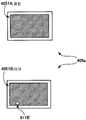
도 4는, 차트 화상을 갖는 큰 사이즈의 용지(400)에 대하여 판독이 행해질 때에, 용지가, 도 1의 투명 글래스(250)와 상부 커버(260) 사이에 배치될 때까지의 형태를 나타낸 도면이다.FIG. 4 is a diagram showing the form until the paper is disposed between the
여기에서는, 도 3의 큰 사이즈의 용지(400)의 표면(501A)의 상측 부분의 판독을 위해서, 최종적으로, 표면(501A)의 상측 부분이 투명 글래스(250)측을 향하고, 이면(501B)의 상측 부분이 상부 커버(260)측을 향한 상태로 배치되는 경우를 예로 들어서 설명한다.Here, in order to read the upper part of the
우선, 도 4의 (a)에서 나타내는 바와 같이, 도 3의 큰 사이즈의 용지(400)의 표면(501A)의 상측 부분을 투명 글래스(250)측을 향해서 큰 사이즈의 용지(400)가 투명 글래스(250)(즉 원고대) 위에 배치된다. 이 배치 시에는, 이면(501B)에 있어서의 위치 맞춤 화상(801A, 802A, 803A, 804A) 중, 도면의 하측의 2개의 위치 맞춤 화상(803A, 804A)의 삼각 마크의, 중앙 수직 라인(605)으로부터 멀어지는 방향을 향한 정점이, 도 4의 (a)에서 나타내는 바와 같이, 투명 글래스(250)의 하측의 가장자리(250a)의 라인 위에 놓이도록, 하측의 2개의 위치 맞춤 화상(803A, 804A)이, 투명 글래스(250)의 하측의 가장자리(250a)에 대해서 위치 맞춤된다. 이에 따라, 도면의 상하 방향에 대해서, 투명 글래스(250)(즉 원고대)에 대한 큰 사이즈의 용지(400)가 위치 맞춤되게 된다.First, as shown in Fig. 4A, the upper portion of the
다음으로, 도 4의 (b)에서 나타내는 바와 같이, 투명 글래스(250) 위의 큰 사이즈의 용지(400)의 이면(501B)의 상측의 부분 위에, 양면의 전역(全域)이 흑일색으로 되어 있는 흑색지(400a)가 배치되며, 이에 따라 이 상측의 부분은 흑색지(400a)에 의해 완전히 덮인다. 이 흑색지(400a)는, 큰 사이즈의 용지(400)의 에지 부분이 판독에 의해 명확히 인식되도록, 큰 사이즈의 용지(400)에 대해 검은 배경을 부여하기 위한 것이다. 즉, 흑색지(400a)는 큰 사이즈의 용지(400)와 투명 글래스(250)의 단부 사이에 발생하는 극간을 적어도 일부 덮는 것이다. 이 흑색지(400a)는, 덮개판의 일례로서의 배경 부재의 일종이다.Next, as shown in FIG.4 (b), the whole surface of both surfaces becomes black one color on the upper part of the
다음으로, 도 4의 (c)에서 나타내는 바와 같이, 큰 사이즈의 용지(400)의 이면(501B)의 상측의 부분 및 흑색지(400a) 위를 상부 커버(260)가 덮고, 이 상태에서 도 1의 화상 판독부(200)에 의해 판독이 실행된다. 이때의 화상 판독부(200)의 동작에 대해서는 도 1의 설명에 있어서 상술한 바와 같으며, 판독한 차트 화상의 일부를 나타내는 판독 데이터가 판독 화상용 메모리(64)에 기억된다. 단, 통상 모드 시와 달리, 보정량 산출 모드가 설정되어 있는 상황에서는, 이 판독 데이터에 의거한 화상 형성은 행해지지 않는다.Next, as shown in FIG.4 (c), the
다음으로, 이상에서 설명한 절차와 같은 절차를 밟아서 큰 사이즈의 용지(400)의 표면(501A)의 하측의 부분에 대해서 판독이 행해지고, 또한 이면(501B)의 상측의 부분 및 하측의 부분(도 3 참조)에 대해서도 각각 판독이 행해진다. 여기에서, 표면(501A)의 하측의 부분에 대한 판독을 위해서 이 표면(501A)의 하측의 부분이 투명 글래스(250) 위에 배치될 때에는, 이면(501B)의 상측의 2개의 위치 맞춤 화상(801A, 802A)이 투명 글래스(250)의 하측의 가장자리(250a)에 대해서 위치 맞춤된다. 마찬가지로, 이면(501B)의 상측의 부분에 대한 판독에서는, 표면(501A)의 하측의 2개의 위치 맞춤 화상(803A, 804A)이 투명 글래스(250)의 하측의 가장자리(250a)에 대해서 위치 맞춤되고, 이면(501B)의 하측의 부분에 대한 판독에서는, 표면(501A)의 상측의 2개의 위치 맞춤 화상(801A, 802A)이 투명 글래스(250)의 하측의 가장자리(250a)에 대해서 위치 맞춤된다. 이렇게, 어느 판독에 있어서도, 위치 맞춤 화상(801A, 802A) 혹은 위치 맞춤 화상(803A, 804A)을 사용함으로써, 도면의 상하 방향에 대해서, 투명 글래스(250)(즉 원고대)에 대해 큰 사이즈의 용지(400)가 위치 맞춤되게 된다.Next, following the same procedure as described above, the reading is performed on the lower portion of the
이상에서 설명한, 표면(501A)의 상측과 하측의 부분, 및 이면(501B)의 상측과 하측의 부분의 각각의 판독마다 판독 데이터가 생성되어 판독 화상용 메모리(64)에 기억된다.Read data is generated for each reading of the upper and lower portions of the
도 5는, 도 3의 표면(501A)의 상측과 하측의 부분, 및 도 3의 이면(501B)의 상측과 하측의 부분의 각각의 판독 시의 판독 영역을, 도 3의 표면(501A) 및 이면(501B)에 겹쳐서 나타낸 도면이다.FIG. 5 shows reading areas at the time of reading each of the upper and lower portions of the
도 5에서는, 큰 사이즈의 용지(400)의 표면(501A)과 이면(501B)의 각각의 상측 부분과 하측 부분을, 도 4에서 설명한 배치 방식에 따라 배치해서 판독을 차례로 행했을 때의 각 판독 영역이 점선에서 나타내는, 1회째 판독 영역(701), 2회째 판독 영역(702), 3회째 판독 영역(703), 4회째 판독 영역(704)의 4개의 판독 영역으로서 나타나 있으며, 각 판독 영역의 넓이는, 투명 글래스(250)의 넓이(즉 원고대의 넓이)에 대응하는 것이다.In FIG. 5, each reading when the upper part and the lower part of each of the
도 5에 나타내는 바와 같이, 표면(501A)에서는, 1회째 판독 영역(701)과 2회째 판독 영역(702)은, 중앙 수평 라인(602) 부근의 영역에서 서로 겹쳐 있으며, 1매째의 큰 사이즈의 용지(400)의 표면(501A)에 있어서의, 1회째 판독 영역(701) 내의 상측의 부분을 나타내는 판독 데이터와, 2회째 판독 영역(702) 내의 하측의 부분을 나타내는 판독 데이터가, 모두, 중앙 수평 라인(602)의 위치 정보를 포함하게 되어 있다. 이 점은, 이면(501B)에서도 마찬가지이며, 중앙 수평 라인(602)의 위치 정보는, 3회째 판독 영역(703) 내의 상측의 부분을 나타내는 판독 데이터와, 4회째 판독 영역(704) 내의 하측의 부분을 나타내는 판독 데이터 사이에서, 각각 서로 공통의 것으로 되어 있다.As shown in FIG. 5, on the
표면(501A)의 상측과 하측의 부분, 및 이면(501B)의 상측과 하측의 부분의 각각의 판독이 완료되어 각각의 판독 데이터가 판독 화상용 메모리(64)에 기억되면, 도 2의 판독 완료란(2701c)이 유저의 손가락 접촉을 받는다. 판독 완료란(2701c)이 유저의 손가락 접촉을 받으면, 도 1의 컨트롤러(6)는, 지금까지 판독 화상용 메모리(64)에 기억되어 있던, 차트 화상을 갖는 큰 사이즈의 용지(400)의 표면(501A)의 상측 부분과 하측 부분, 및 이면(501B)의 상측 부분과 하측 부분에 각각 대응하는, 2×2=4개의 판독 데이터 각각에 대하여, 4개의 판독 데이터 각각에서 나타나는 검출 화상의 위치 파라미터를 추출한다. 도 5의 표면(501A)의 상측 부분을 예로 들어서 구체적으로 설명하면, 우선 판독한 화상 중에 있어서, 도 4의 (a)의 흑색지(400a)에 기인하는 흑색 부분이, 용지에 대응하는 백색 부분으로 변화하는 개소를 구함으로써 용지의 에지를 검출하고, 이에 따라 에지의 1개의 교점(交點)인 용지의 코너의 위치를 원점(O)(도 5의 표면(501A) 참조)으로서 결정한다. 다음으로, 상단 수평 라인(601), 중앙 수평 라인(602), 좌단 수직 라인(604), 중앙 수직 라인(605), 우단 수직 라인(606)을 각각 검출하여, 6개의 교점(A1, A2, A3, A4, A5, A6)의 각 좌표를 구한다. 이 6개의 좌표의 좌표값이 상술한 검출 화상의 위치 파라미터이다. 표면(501A)의 하측의 부분, 및 이면(501B)의 상측과 하측의 부분의 각각에 대해서도 마찬가지로 해서 6개의 좌표의 좌표값으로 이루어지는 위치 파라미터가 추출된다.When the respective readings of the upper and lower portions of the
다음으로, 도 1의 컨트롤러(6)는, 표면(501A) 및 이면(501B) 각각에 대하여, 차트 화상(도 5 참조)에 있어서의, 상단 수평 라인(601)과 하단 수평 라인(603) 사이의 거리, 좌단 수직 라인(604)과 우단 수직 라인(606) 사이의 거리, 상측의 에지와 상단 수평 라인(601)의 거리, 좌측의 에지와 좌단 수직 라인(604) 사이의 거리 등의 다양한 위치 정보를 산출한다.Next, the
예를 들면, 표면(501A)에 있어서의 상단 수평 라인(601)과 하단 수평 라인(603) 사이의 거리에 대해서는, 우선 표면(501A) 상측 부분을 특정하는 도 3의 식별 화상(801)을 나타내는 데이터를 발견함으로써 4개의 판독 데이터 중에서 표면(501A) 상측 부분의 판독 데이터가 특정되며, 특정된 표면(501A) 상측 부분의 판독 데이터에 의거하여, 상단 수평 라인(601)과 중앙 수직 라인(605)의 교점(A2)의 좌표와, 중앙 수평 라인(602)과 중앙 수직 라인(605)의 교점(A5)의 좌표 사이의 거리가 산출된다. 다음으로, 표면(501A) 하측 부분을 특정하는 도 3의 식별 화상(802)을 나타내는 데이터를 발견함으로써, 4개의 판독 데이터 중에서 표면(501A) 하측 부분의 판독 데이터가 특정되며, 특정된 표면(501A) 하측 부분의 판독 데이터에 의거하여, 상측 부분과 마찬가지로, 하단 수평 라인(603)과 중앙 수직 라인(605)의 교점의 좌표와, 중앙 수평 라인(602)과 중앙 수직 라인(605)의 교점의 좌표 사이의 거리가 산출된다. 그리고, 상측 부분에서 산출된 상기한 거리와 하측 부분에서 산출된 상기한 거리의 합으로서, 상단 수평 라인(601)과 하단 수평 라인(603) 사이의 거리가 구해진다.For example, about the distance between the upper
또한, 표면(501A)에 있어서의 좌단 수직 라인(604)과 우단 수직 라인(606) 사이의 거리에 대해서는, 상술한 바와 같이 특정된 표면(501A) 상측 부분의 판독 데이터에 의거하여, 우선 중앙 수평 라인(602)과 좌단 수직 라인(604)의 교점(A4)의 좌표와, 중앙 수평 라인(602)과 우단 수직 라인(606)의 교점(A6)의 좌표 사이의 거리가 산출된다. 다음으로, 상술한 바와 같이 특정된 표면(501A) 하측 부분의 판독 데이터에 의거하여, 상측 부분과 마찬가지로, 중앙 수평 라인(602)과 좌단 수직 라인(604)의 교점의 좌표와, 중앙 수평 라인(602)과 우단 수직 라인(606)의 교점의 좌표 사이의 거리가 산출된다. 그리고, 상측 부분에서 산출된 상기한 거리와 하측 부분에서 산출된 상기한 거리의 평균으로서, 표면(501A)에 있어서의 좌단 수직 라인(604)과 우단 수직 라인(606) 사이의 거리가 구해진다.In addition, the distance between the left end
또한, 표면(501A)에 있어서의, 상측의 에지와 상단 수평 라인(601)의 거리, 및 좌측의 에지와 좌단 수직 라인(604) 사이의 거리에 대해서는, 상술한 바와 같이 특정된 표면(501A) 상측 부분의 판독 데이터에 의거하여, 상단 수평 라인(601)과 좌단 수직 라인(604)의 교점의 좌표의, 좌단 수직 라인(604)에 따른 방향의 좌표 성분, 및 상단 수평 라인(601)에 따른 방향의 좌표 성분으로서 구할 수 있다.In addition, about the distance of the upper edge and the upper
여기에서, 상단 수평 라인(601)과 하단 수평 라인(603) 사이의 거리는, 도 5의 용지의 장척 방향에 대한 차트 화상의 배율을 결정하는 것이며, 좌단 수직 라인(604)과 우단 수직 라인(606) 사이의 거리는, 도 5의 용지의 단척(短尺) 방향에 대한 차트 화상의 배율을 결정하는 것이다. 또한, 상측의 에지와 상단 수평 라인(601)의 거리, 및 좌측의 에지와 좌단 수직 라인(604) 사이의 거리는, 큰 사이즈의 용지에 있어서의 차트 화상의 위치를 결정하는 것이다. 도 1의 컨트롤러(6)는, 이들 2종류의 배율과, 큰 사이즈의 용지에 있어서의 차트 화상의 위치가 적정한 값으로 되기 위해서 필요한 화상 형성 위치 및 배율의 보정량을 산출한다.Here, the distance between the upper
이상의 위치 정보의 산출 및 보정량의 산출이, 이면(501B)에 대해서도 표면(501A)과 마찬가지로 해서 행해지며, 최종적으로, 큰 사이즈의 용지에 있어서의 표면용 보정량과 이면용 보정량이 산출되게 된다.The above calculation of the positional information and the calculation of the correction amount are also performed on the
보정량의 산출이 행해지면, 다음으로 도 1의 컨트롤러(6)는, 식별 화상 데이터에 의거하여, 큰 사이즈의 용지가 취출된 트레이(이 설명의 예에서는 도 1의 제1 트레이(70A))를 특정하여, 그 특정된 트레이에 대응하는 메모리에 보정량(표면용 보정량과 이면용 보정량)을 기억시킨다. 여기에서, 이 보정량의 기억 시에는, 메모리에 원래 기억되어 있던 보정량에 대하여, 상술한 과정을 거쳐서 산출된 새로운 보정량이 덮어써진다.When the correction amount is calculated, the
이상이, 제1 실시형태의 화상 형성 장치(10)에 있어서의, 투명 글래스(250)의 넓이(용지대의 넓이)보다 큰 사이즈의 용지 위에서의 화상 형성 위치 등에 대한 보정량 산출의 설명이다.The above is the explanation of the calculation of the correction amount for the image forming position on the paper of the size larger than the width (the width of the paper zone) of the
이렇게, 이 제1 실시형태의 화상 형성 장치(10)에서 사용되는 차트 화상에서는, 표면(501A) 및 이면(501B) 상측 부분을 투명 글래스(250)에 배치할 때에는, 이면(501B) 및 표면(501A)의 중앙 수평 라인(602)의 하측의 위치 맞춤 화상(803A, 804A)을 투명 글래스(250)의 하측의 가장자리(250a)에 위치 맞춤시키고, 표면(501A) 및 이면(501B) 하측 부분을 투명 글래스(250)에 배치할 때에는, 이면(501B) 및 표면(501A)의 중앙 수평 라인(602)의 상측의 위치 맞춤 화상(801A, 802A)을 투명 글래스(250)의 하측의 가장자리(250a)에 위치 맞춤함으로써, 어느 판독 데이터에 대해서도 확실히 중앙 수평 라인(602)의 위치 정보가 포함됨과 함께, 용지의 코너가 투명 글래스의 가장자리로부터 떨어지게 되어 있다. 이 결과, 표면(501A) 및 이면(501B) 각각에 있어서의 상측의 부분과 하측의 부분의 판독 시에, 유저에 의한 큰 사이즈의 용지(400)의 배치 실수에 의해 공통 부분(예를 들면 중앙 수평 라인(602))에 관한 데이터가 없는 판독 데이터가 생성되어 보정량을 산출할 수 없는 등의 판독 실패나, 판독 화상 해석 시에 용지 에지 위치 검지를 할 수 없는 등의 판독 실패는, 이 제1 실시형태의 화상 형성 장치(10)에서는 일어나기 어렵게 되어 있다.Thus, in the chart image used by the
특히, 투명 글래스(250)의 가장자리(250a)가 표지(標識)로서 이용됨으로써 위치 맞춤을 위한 부가적인 표지가 불필요하여, 용지의 위치 맞춤이 용이하게 되어 있다.In particular, since the
이상이 제1 실시형태의 설명이다.The above is description of 1st Embodiment.
한편, 이상의 설명에서는, 큰 사이즈의 용지를 사용해서 복수 회의 분할된 판독을 행하는 예에 대하여 설명했지만, 본 발명은 이것으로는 한정되지 않으며, 한번에 판독 가능한 것에 적용되어도 된다.In addition, in the above description, although the example which reads divided into multiple times using the paper of large size was demonstrated, this invention is not limited to this, You may apply to what can be read at once.
또한, 이상의 설명에서는, 덮개판의 일례인 배경 부재로서 흑색지가 채용되어 있지만, 본 발명은 이것으로는 한정되지 않으며, 흑색 이외의 색의 종이 을 사용해도 되며, 또한 특정한 모양이나 화상이 형성된 종이를 사용해도 된다. 또한, 종이가 아닌 플라스틱이나 아크릴 등의 재질의 배경 부재를 사용해도 된다. 덮개판으로서 요구되는 기능으로서는, 용지의 에지를 검출할 수 있는 것이면 적절히 변경 가능하며, 즉 용지와 덮개판을 구별할 수 있는 것이면 된다.In addition, in the above description, although black paper is employ | adopted as a background member which is an example of a cover plate, this invention is not limited to this, The paper of colors other than black may be used, and the paper with a specific pattern and an image is formed. You may use it. Moreover, you may use the background member made of materials, such as plastic and acryl, not paper. As a function required as a cover plate, if the edge of a paper can be detected, it can change suitably, ie, what can distinguish a paper and a cover board may be sufficient.
또한, 1매의 용지를 복수의 영역으로 나눠, 복수 회로 분할해서 판독을 행하는 경우에는, 판독 누락을 방지하기 위해서, 영역을 구별할 수 있는 화상을 형성하는 것도 가능하다. 영역을 구별할 수 있는 화상으로서는 예를 들면 문자나 기호 등을 들 수 있다. 또한, 동일한 문자나 기호이어도, 화상의 농도나 수를 변화시킴으로써 영역을 구별시키는 화상으로 할 수도 있다. 또한, 이러한 화상은 위치 맞춤 화상과 겸용시키는 것도 가능하다.In addition, when reading a sheet by dividing a sheet into a plurality of regions and dividing the circuit into a plurality of circuits, it is also possible to form an image that can distinguish the regions in order to prevent the reading from being lost. As an image which can distinguish an area | region, a letter, a symbol, etc. are mentioned, for example. Moreover, even if it is the same letter and a symbol, it can also be set as the image which distinguishes an area by changing the density and number of images. In addition, such an image can also be used as a positioning image.
또한, 복수의 영역에 대하여, 판독에 순번을 마련하고자 하는 경우에는, 영역을 구별할 수 있는 화상을 순번이 인식할 수 있도록, 예를 들면 숫자 등으로 형성할 수 있다.In addition, when the order of reading is to be provided for a plurality of areas, for example, numbers and the like can be formed so that the images can distinguish the areas.
또한, 이상의 설명에서는, 위치 맞춤 화상은 투명 글래스(250)의 가장자리에 대해서 위치 맞춤되어 있지만, 위치 맞춤 화상으로서는, 측정 대상으로 되는 검출용 화상(예를 들면 중앙 수평 라인(602))이 판독 영역 밖에 배치되지 않고, 또한 용지의 단부와 판독 영역의 경계 사이에 극간이 생기는 위치에 용지를 위치 결정하는 것이 필요하며, 보다 바람직하게는, 배경 부재나 상부 커버 위에 형성된 표지가 되는 화상과의 경계 위치에 형성되는 것이 좋다.In addition, in the above description, although the alignment image is aligned with respect to the edge of the
또한, 이상의 설명에서는, 위치 맞춤 화상으로서 마크가 사용되고 있지만, 본 발명은, 마크 외에도 선 등의 다양한 식별 도형이나 식별 기호를 사용할 수도 있으며, 또한 용지를 이 범위에 배치하도록 범위를 지정하는 위치 맞춤 화상 을 사용해도 된다.In addition, although the mark is used as an alignment image in the above description, in this invention, various identification figures and identification symbols, such as a line, can also be used besides a mark, and also the alignment image which designates a range so that a sheet may be arrange | positioned in this range. You can also use
[제2 실시형태][Second Embodiment]
다음으로, 제2 실시형태의 화상 형성 장치에 대하여 설명한다.Next, the image forming apparatus of the second embodiment will be described.
제2 실시형태의 화상 형성 장치가, 도 1에 나타내는 제1 실시형태의 화상 형성 장치(10)와 다른 점은, 제1 실시형태의 화상 형성 장치(10)의 차트 화상용 메모리(65)에 기억되어 있는 차트 화상 데이터와는 다른 차트 화상 데이터가 차트 화상용 메모리에 기억되어 있는 점이며, 이 점을 제외하고, 제2 실시형태의 화상 형성 장치의 구성이나 동작은, 제1 실시형태의 화상 형성 장치(10)와 동일하다. 여기에서, 이 제2 실시형태에 있어서의 차트 화상 데이터로 나타나는 차트 화상은, 도 3에 나타내는 제1 실시형태에 있어서의 차트 화상과는 다른 위치 맞춤 화상을 갖고 있는 점만이 다르며, 그 이외의 점에서는, 도 3에 나타내는 제1 실시형태에 있어서의 차트 화상과 동일하다. 이렇게 차트 화상에 대해서는 제1 실시형태와 차이가 있지만, 제2 실시형태의 화상 형성 장치에서도, 제1 실시형태의 화상 형성 장치와 마찬가지의 절차로 보정량의 산출이 행해진다. 이하의 설명에서는, 제1 실시형태와 다른 점에 초점을 좁혀서 설명을 행하며, 제1 실시형태와 동일한 요소에 대해서는 중복 설명은 생략한다. 또한, 도면에서는 제1 실시형태와 동일한 요소에 대해서는 동일한 부호를 부여하는 것으로 한다.The image forming apparatus of the second embodiment differs from the
도 6은, 제2 실시형태에 있어서의 차트 화상을 갖는 큰 사이즈의 용지(402)에 대해서 판독이 행해질 때에, 용지(402)가 투명 글래스(250) 위에 위치 맞춤되는 형태를 나타낸 도면이다.FIG. 6 is a diagram illustrating a form in which the
이 도 6에서는, 예로서, 큰 사이즈의 용지(402)의 표면의 상측 부분의 판독을 위해서, 표면의 상측 부분이 투명 글래스(250)측을 향해서 배치되는 경우가 나타나 있다. 이 경우, 도 6에 나타내는 바와 같이, 큰 사이즈의 용지(402)의 이면(502B)이 외측으로부터 시인 가능해진다. 도 6의 큰 사이즈의 용지(402)에 있어서의 차트 화상은, 도 3의 큰 사이즈의 용지(400)에 있어서의 차트 화상에 있어서, 삼각 마크로 나타나는, 중앙 수평 라인(602)의 상측의 2개의 위치 맞춤 화상(801A, 802A), 및 하측의 2개의 위치 맞춤 화상(803A, 804A)을, 중앙 수평 라인(602)의 상측에서 수평 방향으로 연장되는 1개의 라인으로서 나타나는 위치 맞춤 화상(801B), 및 중앙 수평 라인(602)의 하측에서 수평 방향으로 연장되는 1개의 라인으로서 나타나는 위치 맞춤 화상(802B)으로 치환한 것이다. 즉, 도 6에서는 도시하고 있지 않지만, 도 6의 이면(502B)과 반대측인 표면에도, 마찬가지의 위치 맞춤 화상(801B, 802B)이, 6개의 라인(601, 602, 603, 604, 605, 606)으로 이루어지는 검출용 화상과 함께 기재되어 있다. 또한, 이면(502B)의 상측 부분과 하측 부분, 및 그 반대측인 표면의 상측 부분과 하측 부분의 4개의 부분에는, 이들을 서로 식별하기 위한, 도 3과 같은 4개의 식별 화상이 각각 기재되어 있으며, 도 6에서는, 그 중 이면(502B) 위의 2개의 식별 화상(803, 804)만이 도시되어 있다.In FIG. 6, as an example, the upper part of the surface is arrange | positioned toward the
큰 사이즈의 용지(402)의 표면의 상측 부분의 판독을 위해서, 표면의 상측 부분이 투명 글래스(250)에 배치될 때에는, 이면(502B)에 있어서의 위치 맞춤 화상(801B, 802B) 중, 도면의 하측의 위치 맞춤 화상(802B)의 라인이, 도 6에서 나타내는 바와 같이 투명 글래스(250)의 하측의 가장자리(250a)의 라인 위에 놓이도록, 하측의 위치 맞춤 화상(802B)이, 투명 글래스(250)의 하측의 가장자리(250a)에 대해서 위치 맞춤된다. 이에 따라, 도면 상하 방향에 대하여, 투명 글래스(250)(즉 원고대)에 대해서 큰 사이즈의 용지(402)가 위치 맞춤되게 된다.In order to read the upper part of the surface of the
이렇게 배치된 후, 도 4의 (b) 및 도 4의 (c)와 마찬가지로, 도 4의 (b)에서 나타내는 흑색지(400a)나 상부 커버(260)로 덮여서 판독이 실행되어, 그 판독 데이터가 생성된다.After this arrangement, the reading is performed by covering with the
다음으로, 이상에서 설명한 절차와 동일한 절차를 밟아서 큰 사이즈의 용지(402)의 표면의 하측의 부분에 대하여 판독이 행해지며, 또한 이면(502B)의 상측의 부분 및 하측의 부분에 대해서도 각각 판독이 행해진다. 여기에서, 표면의 하측의 부분에 대한 판독에서 이 표면의 하측의 부분이 투명 글래스(250) 위에 배치될 때에는, 이면(502B)의 상측의 위치 맞춤 화상(801B)이 투명 글래스(250)의 하측의 가장자리(250a)에 대해서 위치 맞춤된다. 이면(502B)의 상측의 부분 및 하측의 부분의 판독에서도, 표면과 마찬가지로, 표면의 2개의 위치 맞춤 화상을 사용해서 위치 맞춤이 행해진다. 이렇게, 어느 판독에 있어서도, 위치 맞춤 화상(801B, 802B)을 사용함으로써, 도면의 상하 방향에 대하여, 투명 글래스(250)(즉 원고대)에 대해서 큰 사이즈의 용지(402)가 위치 맞춤되게 된다.Next, a reading is performed on the lower portion of the surface of the large-
이상에서 설명한, 표면의 상측과 하측의 부분, 및 이면(502B)의 상측과 하측의 부분의 각각의 판독마다 판독 데이터가 생성되어 판독 화상용 메모리(64)에 기억된다. 그 후의 보정량 산출의 흐름에 대해서는 제1 실시형태와 마찬가지이므로 중복 설명은 생략한다.Read data is generated for each read of the upper and lower portions of the front surface and the upper and lower portions of the
이 제2 실시형태에서도 제1 실시형태와 마찬가지로, 어느 판독 데이터에 대해서도 확실히 중앙 수평 라인(602)의 위치 정보가 포함됨과 함께, 용지의 코너가 투명 글래스의 가장자리로부터 떨어지게 되어 있다. 이 결과, 표면 및 이면의 각각에 있어서의 상측의 부분과 하측의 부분의 판독 시에, 유저에 의한 큰 사이즈의 용지(402)의 배치 실수에 의해 공통 부분(예를 들면 중앙 수평 라인(602))에 관한 데이터가 없는 판독 데이터가 생성되어 보정량을 산출할 수 없는 등의 판독 실패나, 판독 화상 해석 시에 용지 에지 위치 검지를 할 수 없는 등의 판독 실패는, 이 제2 실시형태에서는 일어나기 어렵게 되어 있다.In this second embodiment, similarly to the first embodiment, the positional information of the center
또한, 투명 글래스(250)의 가장자리(250a)가 표지로서 이용됨으로써 위치 맞춤을 위한 부가적인 표지가 불필요하며, 용지의 위치 맞춤이 용이하게 되어 있다.In addition, since the
[제3 실시형태][Third embodiment]
다음으로, 제3 실시형태의 화상 형성 장치에 대하여 설명한다.Next, the image forming apparatus of the third embodiment will be described.
제3 실시형태의 화상 형성 장치가, 도 1에 나타내는 제1 실시형태의 화상 형성 장치(10)와 다른 점은, 제1 실시형태의 화상 형성 장치(10)의 차트 화상용 메모리(65)에 기억되어 있는 차트 화상 데이터와는 다른 차트 화상 데이터가 차트 화상용 메모리에 기억되어 있는 점이며, 이 점을 제외하고, 제3 실시형태의 화상 형성 장치의 구성이나 동작은, 제1 실시형태의 화상 형성 장치(10)와 동일하다. 여기에서, 이 제3 실시형태에 있어서의 차트 화상 데이터에서 나타나는 차트 화상은, 도 3에 나타내는 제1 실시형태에 있어서의 차트 화상과는 다른 위치 맞춤 화상을 갖고 있는 점만이 다르며, 그 이외의 점에서는, 도 3에 나타내는 제1 실시형태에 있어서의 차트 화상과 동일하다. 이렇게 차트 화상에 대해서는 제1 실시형태와 차이가 있지만, 제3 실시형태의 화상 형성 장치에서도, 제1 실시형태의 화상 형성 장치와 마찬가지의 절차로 보정량의 산출이 행해진다. 이하의 설명에서는, 제1 실시형태와 다른 점에 초점을 좁혀서 설명을 행하며, 제1 실시형태와 동일한 요소에 대해서는 중복 설명은 생략한다. 또한, 도면에서는 제1 실시형태와 동일한 요소에 대해서는 동일한 부호를 부여하는 것으로 한다.The image forming apparatus of the third embodiment differs from the
도 7은, 제3 실시형태에 있어서의 차트 화상을 갖는 큰 사이즈의 용지(403)에 대해서 판독이 행해질 때에, 용지(403)가 투명 글래스(250) 위에 위치 맞춤되는 형태를 나타낸 도면이다.FIG. 7 is a diagram illustrating a form in which the
이 도 7에서는, 예로서, 큰 사이즈의 용지(403)의 표면의 상측 부분의 판독을 위해서, 표면의 상측 부분이 투명 글래스(250)측을 향해서 배치되는 경우가 나타나 있다.In this FIG. 7, as an example, the upper part of the surface is arrange | positioned toward the
이 경우, 도 7의 (a)에 나타내는 바와 같이, 큰 사이즈의 용지(403)의 이면(503B)이 외측으로부터 시인(視認) 가능해진다. 도 7의 (a)의 큰 사이즈의 용지(403)에 있어서의 차트 화상은, 도 3의 큰 사이즈의 용지(400)에 있어서의 차트 화상에 있어서, 중앙 수평 라인(602)의 상측이며 용지(400)의 에지 부근에 각각 구비되어 있는 2개의 위치 맞춤 화상(801A, 802A), 및 중앙 수평 라인(602)의 하측이며 용지(400)의 에지 부근에 각각 구비되어 있는 2개의 위치 맞춤 화상(803A, 804A)을, 중앙 수평 라인(602)의 상측이며 수직 라인(605)에 더 치우친 위치에 각각 구비되어 있는 2개의 위치 맞춤 화상(801C, 802C), 및 중앙 수평 라인(602)의 하측이며 수직 라인(605)에 더 치우친 위치에 각각 구비되어 있는 2개의 위치 맞춤 화상(803C, 804C)으로 치환한 것이다. 즉, 도 7의 (a)에서는 도면에 나타나 있지 않지만, 도 7의 (a)의 이면(503B)과 반대측인 표면에도, 마찬가지의 위치 맞춤 화상(801C, 802C, 803C, 804C)이, 6개의 라인(601, 602, 603, 604, 605, 606)으로 이루어지는 검출용 화상과 함께 기재되어 있다. 또한, 이면(503B)의 상측 부분과 하측 부분, 및 그 반대측인 표면의 상측 부분과 하측 부분의 4개의 부분에는, 이들을 서로 식별하기 위한, 도 3과 같은 4개의 식별 화상이 각각 기재되어 있으며, 도 7의 (a)에서는, 그 중 이면(503B) 위의 2개의 식별 화상(803, 804)만이 도시되어 있다.In this case, as shown to Fig.7 (a), the
다음으로, 도 7의 (b)에서 나타내는 바와 같이, 투명 글래스(250) 상의 큰 사이즈의 용지(403)의 이면(503B)의 상측의 부분 위에 흑색지(403a)가 배치되며, 이에 따라 이 상측의 부분은, 흑색지(403a)에 의해 완전히 덮인다. 여기에서, 도 4의 (b)에 나타내는 흑색지(400a)와 마찬가지로, 도 7의 (b)에 나타내는 흑색지(403a)는, 큰 사이즈의 용지(403)의 에지 부분이 판독에 의해 명확히 인식되도록, 큰 사이즈의 용지(403)에 대해 검은 배경을 부여하기 위한 것이다. 즉, 흑색지(403a)는 큰 사이즈의 용지(403)와 투명 글래스(250)의 단부 사이에 발생하는 극간을 적어도 일부 덮는 것이다. 단, 도 4의 (b)에 나타내는 흑색지(400a)와 달리, 도 7의 (b)에 나타내는 흑색지(403a)는, 용지(403)의 이면(503B)의 상측의 부분을 덮는 면과는 반대측의 면의 가장자리 부근에, 삼각 형상의 백색의 표지 화상(811C, 812C)이 기재되어 있으며, 이 흑색지(403a)는, 한쪽의 면에 있어서의 이 표지 화상(811C, 812C)을 제외하고, 양면의 전역이 흑일색으로 되어 있다. 여기에서, 투명 글래스(250)는, 투명 글래스(250) 주위의 면보다 조금 오목한 위치에 설치되어 있으며, 이 때문에, 투명 글래스(250)의 가장자리와 그 주위의 사이에는 단차가 존재한다. 이 제3 실시형태에 있어서의 차트 화상의 판독 시에는, 흑색지(403a)는, 투명 글래스(250)의 상측의 가장자리(250c)에 있어서의 단차, 및 좌측의 가장자리(250b)에 있어서의 단차의 양쪽에 맞닿으며, 이에 따라 흑색지(403a)가 투명 글래스(250)에 대해서 위치 맞춤된다. 이렇게 위치 맞춤된 흑색지(403a)의 표지 화상(811C, 812C)에 대하여, 도 7의 (a)의 이면(503B)의 하측의 2개의 위치 맞춤 화상(803C, 804C)이, 도 7의 (b)에 나타내는 바와 같이 위치 맞춤된다. 이에 따라, 도면의 상하 방향 및 좌우 방향에 대하여, 투명 글래스(250)(즉 원고대)에 대해서 큰 사이즈의 용지(403)가 위치 맞춤되게 된다.Next, as shown in FIG. 7B,
이렇게 배치된 후, 도 4의 (c)와 마찬가지로, 상부 커버(260)로 덮여서 판독이 실행되어, 그 판독 데이터가 생성된다.After this arrangement, as in FIG. 4C, the reading is executed while covered with the
다음으로, 이상 설명한 절차와 동일한 절차를 밟아서 큰 사이즈의 용지(403)의 표면의 하측의 부분에 대하여 판독이 행해지며, 또한 이면(503B)의 상측의 부분 및 하측의 부분에 대해서도 각각 판독이 행해진다. 여기에서, 표면의 하측의 부분에 대한 판독에서 이 표면의 하측의 부분이 투명 글래스(250) 위에 배치될 때에는, 이면(503B)의 상측의 위치 맞춤 화상(801C, 802C)이, 도 7의 (b)에서 설명한 바와 같이 위치 맞춤된 흑색지(403a)의 표지 화상(811C, 812C)에 대해서 위치 맞춤된다. 이면(503B)의 상측의 부분 및 하측의 부분의 판독에서도, 표면과 마찬가지로, 표면의 4개의 위치 맞춤 화상을 사용해서 위치 맞춤이 행해진다. 이렇게, 어느 판독에 있어서도, 상측의 위치 맞춤 화상(801C, 802C) 혹은 하측의 위치 맞춤 화상(803C, 804C)을 사용함으로써, 도면의 상하 방향 및 좌우 방향에 대하여, 투명 글래스(250)(즉 원고대)에 대해서 큰 사이즈의 용지(403)가 위치 맞춤되게 된다.Next, a reading is performed on the lower portion of the surface of the large-
이상 설명한, 표면의 상측과 하측의 부분, 및 이면(503B)의 상측과 하측의 부분의 각각의 판독마다 판독 데이터가 생성되어 판독 화상용 메모리(64)에 기억된다. 그 후의 보정량 산출의 흐름에 대해서는 제1 실시형태와 마찬가지이므로 중복 설명은 생략한다.The read data is generated for each read of the upper and lower portions of the front surface and the upper and lower portions of the
이 제3 실시형태에서도, 제1 실시형태와 마찬가지로, 어느 판독 데이터에 대해서도 확실히 중앙 수평 라인(602)의 위치 정보가 포함됨과 함께, 용지의 코너가 투명 글래스의 가장자리로부터 떨어지게 되어 있다. 이 결과, 표면 및 이면의 각각에 있어서의 상측의 부분과 하측의 부분의 판독 시에, 유저에 의한 큰 사이즈의 용지(403)의 배치 실수에 의해 공통 부분(예를 들면 중앙 수평 라인(602))에 관한 데이터가 없는 판독 데이터가 생성되어 보정량을 산출할 수 없는 등의 판독 실패나, 판독 화상 해석 시에 용지 에지 위치 검지를 할 수 없는 등의 판독 실패는, 이 제3 실시형태의 화상 형성 장치에서는 일어나기 어렵게 되어 있다.Also in this third embodiment, similarly to the first embodiment, the position information of the center
또한, 위치 맞춤된 흑색지(403a)의 표지 화상(811C, 812C)을 표지로서 이용하는 것만으로 용지의 위치 맞춤을 실행할 수 있어, 용지의 위치 맞춤이 용이하게 되어 있다.Further, the paper can be aligned by simply using the
특히, 이 제3 실시형태에서는 도면의 좌우 방향에 대해서도 큰 사이즈의 용지(403)가 위치 맞춤되기 때문에, 도면의 좌우 방향으로 큰 사이즈의 용지(403)가 투명 글래스(250)(즉 원고대)로부터 벗어나게 되는 등의 사태도 회피되어 있다.In particular, in this third embodiment, since the
[제4 실시형태][Fourth Embodiment]
다음으로, 제4 실시형태의 화상 형성 장치에 대하여 설명한다.Next, the image forming apparatus of the fourth embodiment will be described.
제4 실시형태의 화상 형성 장치가, 도 1에 나타내는 제1 실시형태의 화상 형성 장치(10)와 다른 점은, 제1 실시형태의 화상 형성 장치(10)의 차트 화상용 메모리(65)에 기억되어 있는 차트 화상 데이터와는 다른 차트 화상 데이터가 차트 화상용 메모리에 기억되어 있는 점이며, 이 점을 제외하고, 제4 실시형태의 화상 형성 장치의 구성이나 동작은, 제1 실시형태의 화상 형성 장치(10)와 동일하다. 여기에서, 이 제4 실시형태에 있어서의 차트 화상 데이터로 나타나는 차트 화상은, 도 3에 나타내는 제1 실시형태에 있어서의 차트 화상과는 다른 위치 맞춤 화상을 갖고 있는 점만이 다르며, 그 이외의 점에서는, 도 3에 나타내는 제1 실시형태에 있어서의 차트 화상과 동일하다. 이렇게 차트 화상에 대해서는 제1 실시형태와 차이가 있지만, 제4 실시형태의 화상 형성 장치에서도, 제1 실시형태의 화상 형성 장치와 마찬가지의 절차로 보정량의 산출이 행해진다. 이하의 설명에서는, 제1 실시형태와 다른 점에 초점을 좁혀서 설명을 행하며, 제1 실시형태와 동일한 요소에 대해서는 중복 설명은 생략한다. 또한, 도면에서는 제1 실시형태와 동일한 요소에 대해서는 동일한 부호를 부여하는 것으로 한다.The image forming apparatus of the fourth embodiment differs from the
도 8은, 제4 실시형태에 있어서의 차트 화상을 갖는 큰 사이즈의 용지(404)에 대해서 판독이 행해질 때에, 용지(404)가 투명 글래스(250) 위에 위치 맞춤되는 형태를 나타낸 도면이다.FIG. 8 is a diagram illustrating a form in which the
이 도 8에서는, 예로서, 큰 사이즈의 용지(404)의 표면의 상측 부분의 판독을 위해서, 표면의 상측 부분이 투명 글래스(250)측을 향해서 배치되는 경우가 나타나 있다. 이 경우, 도 8의 (a)에 나타내는 바와 같이, 큰 사이즈의 용지(404)의 이면(504B)이 외측으로부터 시인 가능해진다. 도 8의 (a)에 나타내는 큰 사이즈의 용지(404)에 있어서의 차트 화상은, 도 3의 큰 사이즈의 용지(400)에 있어서의 차트 화상에 있어서, 삼각 마크로 나타나는, 중앙 수평 라인(602)의 상측의 2개의 위치 맞춤 화상(801A, 802A), 및 하측의 2개의 위치 맞춤 화상(803A, 804A)을, 중앙 수평 라인(602)의 상측에 설치된, 수평 방향으로 연장되는 1개의 라인 형상의 위치 맞춤 화상(801D)과 화살표 형상의 위치 맞춤 화상(802D), 및 중앙 수평 라인(602)의 하측에 설치된, 수평 방향으로 연장되는 1개의 라인 형상의 위치 맞춤 화상(803D)과 화살표 형상의 위치 맞춤 화상(804D)으로 치환한 것이다. 즉, 도 8에서는 도시되어 있지 않지만, 도 8의 이면(504B)과 반대측인 표면에도, 마찬가지의 위치 맞춤 화상(801D, 802D, 803D, 804D)이, 6개의 라인(601, 602, 603, 604, 605, 606)으로 이루어지는 검출용 화상과 함께 기재되어 있다. 또한, 이면(504B)의 상측 부분과 하측 부분, 및 그 반대측인 표면의 상측 부분과 하측 부분의 4개의 부분에는, 이들을 서로 식별하기 위한, 도 3과 동일한 4개의 식별 화상이 각각 기재되어 있으며, 도 8의 (a)에서는, 그 중의 이면(504B) 위의 2개의 식별 화상(803, 804)만이 도시되어 있다.In FIG. 8, as an example, the case where the upper part of the surface is arrange | positioned toward the
큰 사이즈의 용지(404)의 표면의 상측 부분의 판독을 위해서, 표면의 상측 부분이 투명 글래스(250)에 배치될 때에는, 도 8의 (a)에 나타내는 바와 같이, 이면(504B)에 있어서의 라인 형상의 위치 맞춤 화상(801D, 803D) 중 도면의 하측의 위치 맞춤 화상(803D)의 라인이 투명 글래스(250)의 하측의 가장자리(250a)의 라인 위에 놓이도록, 하측의 위치 맞춤 화상(803D)이, 투명 글래스(250)의 하측의 가장자리(250a)에 대해서 위치 맞춤된다. 이에 따라, 도면의 상하 방향에 대하여, 투명 글래스(250)(즉 원고대)에 대해서 큰 사이즈의 용지(404)가 위치 맞춤되게 된다.In order to read the upper portion of the surface of the large-
다음으로, 도 8의 (b)에서 나타내는 바와 같이, 투명 글래스(250) 위의 큰 사이즈의 용지(404)의 이면(504B)의 상측의 부분 위에 흑색지(404a)가 배치되며, 이에 따라 이 상측의 부분은, 흑색지(404a)에 의해 완전히 덮인다. 여기에서, 도 4의 (b)에 나타내는 흑색지(400a)와 마찬가지로, 도 8의 (b)에 나타내는 흑색지(404a)는, 큰 사이즈의 용지(404)의 에지 부분이 판독에 의해 명확히 인식되도록, 큰 사이즈의 용지(404)에 대해 검은 배경을 부여하기 위한 것이다. 즉, 흑색지(404a)는 큰 사이즈의 용지(404)와 투명 글래스(250)의 단부 사이에 발생하는 극간을 적어도 일부 덮는 것이다. 단, 도 4의 (b)에 나타내는 흑색지(400a)와 달리, 도 8의 (b)에 나타내는 흑색지(404a)는, 용지(404)의 이면(504B)의 상측의 부분을 덮는 면과는 반대측의 면의 가장자리 부근에, 화살표 형상의 백색의 표지 화상(811D)이 기재되어 있으며, 이 흑색지(404a)는, 한쪽의 면의 이 표지 화상(811D)을 제외하고, 양면의 전역이 흑일색으로 되어 있다. 여기에서, 투명 글래스(250)는, 투명 글래스(250) 주위의 면보다 조금 오목한 위치에 설치되어 있으며, 이 때문에, 투명 글래스(250)의 가장자리와 그 주위의 사이에는 단차가 존재한다. 이 제4 실시형태에 있어서의 차트 화상의 판독 시에는, 흑색지(404a)는, 투명 글래스(250)의 상측의 가장자리(250c)에 있어서의 단차, 및 좌측의 가장자리(250b)에 있어서의 단차의 양쪽에 맞닿으며, 이에 따라, 흑색지(404a)가 투명 글래스(250)에 대해서 위치 맞춤된다. 이렇게 위치 맞춤된 흑색지(404a)의 표지 화상(811D)에 대하여, 도 8의 (a)의 이면(504B)의 하측의 화살표 형상의 위치 맞춤 화상(804D)이, 도 8의 (b)에 나타내는 바와 같이 위치 맞춤된다. 이에 따라, 도면의 좌우 방향에 대하여, 투명 글래스(250)(즉 원고대)에 대해서 큰 사이즈의 용지(404)가 위치 맞춤되게 된다.Next, as shown in Fig. 8B,
이렇게 배치된 후, 도 4의 (c)와 마찬가지로, 상부 커버(260)로 덮여서 판독이 실행되어, 그 판독 데이터가 생성된다.After this arrangement, as in FIG. 4C, the reading is executed while covered with the
다음으로, 이상 설명한 절차와 동일한 절차를 밟아서 큰 사이즈의 용지(404)의 표면의 하측의 부분에 대하여 판독이 행해지며, 또한 이면(504B)의 상측의 부분 및 하측의 부분에 대해서도 각각 판독이 행해진다. 여기에서, 표면의 하측의 부분에 대한 판독에서 이 하측의 부분이 투명 글래스(250) 위에 배치될 때에는, 이면(504B)의 상측의 위치 맞춤 화상(801D, 802D)이, 도 8의 (a)에서 설명한 투명 글래스(250)의 하측의 가장자리(250a), 및 도 8의 (b)에서 설명한 위치 맞춤된 흑색지(404a)의 표지 화상(811D)에 대해서 각각 위치 맞춤된다. 이면(504B)의 상측의 부분 및 하측의 부분의 판독에서도, 표면과 마찬가지로, 표면의 4개의 위치 맞춤 화상을 사용해서 위치 맞춤이 행해진다. 이렇게, 어느 판독에 있어서도, 상측의 위치 맞춤 화상(801D, 802D) 혹은 하측의 위치 맞춤 화상(803D, 804D)을 사용함으로써, 도면의 상하 방향 및 좌우 방향에 대하여, 투명 글래스(250)(즉 원고대)에 대해서 큰 사이즈의 용지(404)가 위치 맞춤되게 된다.Next, a reading is performed on the lower portion of the surface of the large-
이상에서 설명한, 표면의 상측과 하측의 부분, 및 이면(504B)의 상측과 하측의 부분의 각각의 판독마다 판독 데이터가 생성되어 판독 화상용 메모리(64)에 기억된다. 그 후의 보정량 산출의 흐름에 대해서는 제1 실시형태와 마찬가지이므로 중복 설명은 생략한다.The read data is generated for each read of the upper and lower portions of the front surface and the upper and lower portions of the
이 제4 실시형태에서도 제1 실시형태와 마찬가지로, 어느 판독 데이터에 대해서도 확실히 중앙 수평 라인(602)의 위치 정보가 포함됨과 함께, 용지의 코너가 투명 글래스의 가장자리로부터 떨어지게 되어 있다. 이 결과, 표면 및 이면의 각각에 있어서의 상측의 부분과 하측의 부분의 판독 시에, 유저에 의한 큰 사이즈의 용지(404)의 배치 실수에 의해 공통 부분(예를 들면 중앙 수평 라인(602))에 관한 데이터가 없는 판독 데이터가 생성되어 보정량을 산출할 수 없는 등의 판독 실패나, 판독 화상 해석 시에 용지 에지 위치 검지를 할 수 없는 등의 판독 실패는, 이 제4 실시형태에서는 일어나기 어렵게 되어 있다.In this fourth embodiment, similarly to the first embodiment, the position information of the center
또한 투명 글래스(250)의 하측의 가장자리(250a), 및 위치 맞춤된 흑색지(404a)의 표지 화상(811D)을 표지로서 이용하는 것만으로 용지의 위치 맞춤을 실행할 수 있어, 용지의 위치 맞춤이 용이하게 되어 있다.Further, the paper can be aligned by simply using the
특히, 이 제4 실시형태에서는 도면의 좌우 방향에 대해서도 큰 사이즈의 용지(404)가 위치 맞춤되기 때문에, 도면의 좌우 방향으로 큰 사이즈의 용지(404)가 투명 글래스(250)(즉 원고대)로부터 벗어나게 되는 등의 사태도 회피되어 있다.In particular, in this fourth embodiment, since the large-
[제5 실시형태][Fifth Embodiment]
다음으로, 제5 실시형태의 화상 형성 장치에 대하여 설명한다.Next, the image forming apparatus of the fifth embodiment will be described.
제5 실시형태의 화상 형성 장치가, 도 1에 나타내는 제1 실시형태의 화상 형성 장치(10)와 다른 점은, 제1 실시형태의 화상 형성 장치(10)의 차트 화상용 메모리(65)에 기억되어 있는 차트 화상 데이터와는 다른 차트 화상 데이터가 차트 화상용 메모리에 기억되어 있음과 함께, 큰 사이즈의 용지(404)에 대해 검은 배경을 부여하기 위한 흑색지에 출력되어 있는 흑색 화상을 나타내는 흑색 화상 데이터도 차트 화상용 메모리에 기억되어 있는 점이며, 이 점을 제외하고, 제5 실시형태의 화상 형성 장치의 구성이나 동작은, 제1 실시형태의 화상 형성 장치(10)와 동일하다. 여기에서, 이 제5 실시형태에 있어서의 차트 화상 데이터에서 나타나는 차트 화상은, 도 3에 나타내는 제1 실시형태에 있어서의 차트 화상과는 다른 위치 맞춤 화상을 갖고 있는 점만이 다르며, 그 이외의 점에서는, 도 3에 나타내는 제1 실시형태에 있어서의 차트 화상과 동일하다. 이렇게 차트 화상에 대해서는 제1 실시형태와 차이가 있지만, 제5 실시형태의 화상 형성 장치에서도, 제1 실시형태의 화상 형성 장치와 마찬가지의 절차로 보정량의 산출이 행해진다. 이하의 설명에서는, 제1 실시형태와 다른 점에 초점을 좁혀서 설명을 행하며, 제1 실시형태와 동일한 요소에 대해서는 중복 설명은 생략한다. 또한, 도면에서는 제1 실시형태와 동일한 요소에 대해서는 동일한 부호를 부여하는 것으로 한다.The image forming apparatus of the fifth embodiment differs from the
도 9는, 제5 실시형태의 화상 형성 장치의 차트 화상용 메모리에 기억되어 있는 흑색 화상 데이터에 의거하여, 이 화상 형성 장치로 출력된 흑색 화상을 나타내는 도면이다.FIG. 9 is a diagram showing a black image output to this image forming apparatus based on the black image data stored in the chart image memory of the image forming apparatus of the fifth embodiment.
도면에 나타내는 흑색 화상은, 주위의 여백 부분을 제외하고 흑일색인 표면(4051A) 위의 화상과, 주위의 여백 부분 및 백색의 표지 화상(811E)을 제외하고 흑일색인 이면(4051B) 위의 화상으로 구성되어 있으며, 유저에 의해 차트 화상의 출력이 지시될 때에(즉, 도 3의 차트 화상 출력란(2701a)에 유저의 손가락이 접촉했을 때), 미리 결정된 사이즈의 용지 위에 양면 출력되는 화상이다. 제5 실시형태에서는 이 흑색 화상을 갖는 흑색지(405a)를 사용해서 차트 화상의 판독이 행해진다.The black image shown in the figure is an image on the surface 4071A which is black except for the margin part around it, and on the back surface 4071B that is black except for the margin part around it and the
도 10은, 제5 실시형태에 있어서의 차트 화상을 갖는 큰 사이즈의 용지(405)에 대하여 판독이 행해질 때에, 용지(405)가 투명 글래스(250) 위에 위치 맞춤되는 형태를 나타낸 도면이다.FIG. 10 is a diagram illustrating a form in which the
이 도 10에서는, 예로서, 큰 사이즈의 용지(405)의 표면의 상측 부분의 판독을 위해서, 표면의 상측 부분이 투명 글래스(250)측을 향해서 배치되는 경우가 나타나 있다. 이 경우, 도 10의 (a)에 나타내는 바와 같이, 큰 사이즈의 용지(405)의 이면(505B)이 외측으로부터 시인 가능해진다. 도 10의 (a)에 나타내는 큰 사이즈의 용지(405)에 있어서의 차트 화상은, 도 3의 큰 사이즈의 용지(400)에 있어서의 차트 화상에 있어서, 삼각 마크로 나타나는, 중앙 수평 라인(602)의 상측의 2개의 위치 맞춤 화상(801A, 802A), 및 하측의 2개의 위치 맞춤 화상(803A, 804A)을, 중앙 수평 라인(602)의 상측에 설치된, 수평 방향으로 연장되는 1개의 라인 형상의 위치 맞춤 화상(801E)과 사각 마크로 나타나는 위치 맞춤 화상(802E), 및 중앙 수평 라인(602)의 하측에 설치된, 수평 방향으로 연장되는 1개의 라인 형상의 위치 맞춤 화상(803E)과 사각 마크로 나타나는 위치 맞춤 화상(804E)으로 치환한 것이다. 즉, 도 10에서는 도시되어 있지 않지만, 도 10의 이면(505B)과 반대측인 표면에도, 마찬가지의 위치 맞춤 화상(801E, 802E, 803E, 804E)이, 6개의 라인(601, 602, 603, 604, 605, 606)으로 이루어지는 검출용 화상과 함께 기재되어 있다. 또한, 이면(505B)의 상측 부분과 하측 부분, 및 그 반대측인 표면의 상측 부분과 하측 부분의 4개의 부분에는, 이들을 서로 식별하기 위한, 도 3과 같은 4개의 식별 화상이 각각 기재되어 있으며, 도 10의 (a)에서는, 그 중의 이면(505B) 위의 2개의 식별 화상(803, 804)만이 도시되어 있다.In this FIG. 10, the case where the upper part of a surface is arrange | positioned toward the
큰 사이즈의 용지(405)의 표면의 상측 부분의 판독을 위해서, 표면의 상측 부분이 투명 글래스(250)에 배치될 때에는, 도 10의 (a)에 나타내는 바와 같이, 이면(505B)에 있어서의 라인 형상의 위치 맞춤 화상(801E, 803E) 중, 도면의 하측의 위치 맞춤 화상(803E)의 라인이 투명 글래스(250)의 하측의 가장자리(250a)의 라인 위에 놓이도록, 하측의 위치 맞춤 화상(803B)이 투명 글래스(250)의 하측의 가장자리(250a)에 대해서 위치 맞춤된다. 이에 따라, 도면의 상하 방향에 대하여, 투명 글래스(250)(즉 원고대)에 대해서 큰 사이즈의 용지(405)가 위치 맞춤되게 된다.When the upper portion of the surface is disposed on the
다음으로, 도 10의 (b)에서 나타내는 바와 같이, 투명 글래스(250) 위의 큰 사이즈의 용지(405)의 이면(505B)의 상측의 부분 위에 흑색지(405a)가 배치되며, 이에 따라 이 상측의 부분은, 흑색지(405a)에 의해 완전히 덮인다. 여기에서, 투명 글래스(250)는, 투명 글래스(250) 주위의 면보다 조금 오목한 위치에 설치되어 있으며, 이 때문에, 투명 글래스(250)의 가장자리와 그 주위의 사이에는 단차가 존재한다. 이 제5 실시형태에 있어서의 차트 화상의 판독 시에는, 흑색지(405a)는, 투명 글래스(250)의 상측의 가장자리(250c)에 있어서의 단차, 및 좌측의 가장자리(250b)에 있어서의 단차의 양쪽에 맞닿으며, 이에 따라 흑색지(405a)가 투명 글래스(250)에 대해서 위치 맞춤된다. 이렇게 위치 맞춤된 흑색지(405a)의 표지 화상(811E)에 대하여, 도 10의 (a)의 이면(505B)의 하측의 사각 마크로 나타나는 위치 맞춤 화상(804E)이, 도 10의 (b)에 나타내는 바와 같이, 흑색지(405a)의 하부의 여백 부분을 사이에 두고 위치 맞춤된다. 이에 따라, 도면의 좌우 방향에 대하여, 투명 글래스(250)(즉 원고대)에 대해서 큰 사이즈의 용지(405)가 위치 맞춤되게 된다. 여기에서, 흑색지(405a)의 주위의 여백 부분이, 흑색지(405a) 전체에 차지하는 비율은 극히 작으며, 상기한 바와 같이 위치 맞춤된 상태에서는, 이면(505B)의 상측의 부분과는 반대측의, 판독 대상으로 되는 표면의 상측의 부분의 주위는, 흑색지(405a)의 흑일색의 부분에 덮인다. 이 때문에, 흑색지(405a)의 여백 부분의 존재가 표면의 상측의 부분에 있어서의 에지 검출에 영향을 주는 것은 피할 수 있다.Next, as shown in Fig. 10B,
이렇게 배치된 후, 도 4의 (c)와 마찬가지로, 상부 커버(260)로 덮여서 판독이 실행되어, 그 판독 데이터가 생성된다.After this arrangement, as in FIG. 4C, the reading is executed while covered with the
다음으로, 이상에서 설명한 절차와 같은 절차를 밟아서 큰 사이즈의 용지(405)의 표면의 하측의 부분에 대하여 판독이 행해지며, 또한 이면(505B)의 상측의 부분 및 하측의 부분에 대해서도 각각 판독이 행해진다. 여기에서, 표면의 하측의 부분에 대한 판독에서 이 하측의 부분이 투명 글래스(250) 위에 배치될 때에는, 이면(505B)의 상측의 위치 맞춤 화상(801E, 802E)가, 도 10의 (a)에서 설명한 투명 글래스(250)의 하측의 가장자리(250a), 및 도 10의 (b)에서 설명한 위치 맞춤된 흑색지(405a)의 표지 화상(811E)에 대해서 각각 위치 맞춤된다. 이면(505B)의 상측의 부분 및 하측의 부분의 판독에서도, 표면과 마찬가지로, 표면의 4개의 위치 맞춤 화상을 사용해서 위치 맞춤이 행해진다. 이렇게, 어느 판독에 있어서도, 상측의 위치 맞춤 화상(801E, 802E) 혹은 하측의 위치 맞춤 화상(803E, 804E)을 사용함으로써, 도면의 상하 방향 및 좌우 방향에 대하여, 투명 글래스(250)(즉 원고대)에 대해서 큰 사이즈의 용지(405)가 위치 맞춤되게 된다.Next, a reading is performed on the lower portion of the surface of the large-
이상에서 설명한, 표면의 상측과 하측의 부분, 및 이면(505B)의 상측과 하측의 부분의 각각의 판독마다 판독 데이터가 생성되어 판독 화상용 메모리(64)에 기억된다. 그 후의 보정량 산출의 흐름에 대해서는 제1 실시형태와 마찬가지이므로 중복 설명은 생략한다.The read data is generated for each read of the upper and lower portions of the front surface and the upper and lower portions of the
이 제5 실시형태에서도, 제1 실시형태와 마찬가지로, 어느 판독 데이터에 대해서도 확실히 중앙 수평 라인(602)의 위치 정보가 포함됨과 함께, 용지의 코너가 투명 글래스의 가장자리로부터 떨어지게 되어 있다. 이 결과, 표면 및 이면의 각각에 있어서의 상측의 부분과 하측의 부분의 판독 시에, 유저에 의한 큰 사이즈의 용지(405)의 배치 실수에 의해 공통 부분(예를 들면 중앙 수평 라인(602))에 관한 데이터가 없는 판독 데이터가 생성되어 보정량을 산출할 수 없는 등의 판독 실패나, 판독 화상 해석 시에 용지 에지 위치 검지를 할 수 없는 등의 판독 실패는, 이 제5 실시형태에서는 일어나기 어렵게 되어 있다.Also in this fifth embodiment, similarly to the first embodiment, the positional information of the center
또한, 투명 글래스(250)의 하측의 가장자리(250a), 및 위치 맞춤된 흑색지(405a)의 표지 화상(811E)을 표지로서 이용하는 것만으로 용지의 위치 맞춤을 실행할 수 있어, 용지의 위치 맞춤이 용이하게 되어 있다.Further, by using the
특히, 이 제5 실시형태에서는 도면의 좌우 방향에 대해서도 큰 사이즈의 용지(405)가 위치 맞춤되기 때문에, 도면의 좌우 방향으로 큰 사이즈의 용지(405)가 투명 글래스(250)(즉 원고대)로부터 벗어나게 되는 등의 사태도 회피되어 있다.In particular, in this fifth embodiment, since the large-
또한, 이 제5 실시형태에서는 흑색지(405a)는, 제5 실시형태의 화상 형성 장치의 차트 화상용 메모리에 기억되어 있는 흑색 화상 데이터에 의거하여 출력되는 것이기 때문에, 흑색지(405a)가 분실 혹은 파손되었을 경우이더라도, 새로운 흑색지(405a)를 입수하는 것이 용이하게 되어 있다.In the fifth embodiment, since the
[제6 실시형태][Sixth Embodiment]
다음으로, 제6 실시형태의 화상 형성 장치에 대하여 설명한다.Next, the image forming apparatus of the sixth embodiment will be described.
제6 실시형태의 화상 형성 장치가, 도 1에 나타내는 제1 실시형태의 화상 형성 장치(10)와 다른 점은, 제1 실시형태의 화상 형성 장치(10)의 차트 화상용 메모리(65)에 기억되어 있는 차트 화상 데이터와는 다른 차트 화상 데이터가 차트 화상용 메모리에 기억되어 있으며, 또한 상부 커버에, 차트 화상을 위치 맞춤하기 위한 표지 화상이 기재되어 있는 점이며, 이 점을 제외하고, 제6 실시형태의 화상 형성 장치의 구성이나 동작은, 제1 실시형태의 화상 형성 장치(10)와 동일하다. 여기에서, 이 제6 실시형태에 있어서의 차트 화상 데이터에서 나타나는 차트 화상은, 도 3에 나타내는 제1 실시형태에 있어서의 차트 화상과는 다른 위치 맞춤 화상을 갖고 있는 점만이 다르며, 그 이외의 점에서는, 도 3에 나타내는 제1 실시형태에 있어서의 차트 화상과 동일하다. 이렇게 차트 화상에 대해서는 제1 실시형태와 차이가 있지만, 제6 실시형태의 화상 형성 장치에서도, 제1 실시형태의 화상 형성 장치와 마찬가지의 절차로 보정량의 산출이 행해진다. 이하의 설명에서는, 제1 실시형태와 다른 점에 초점을 좁혀서 설명을 행하며, 제1 실시형태와 동일한 요소에 대해서는 중복 설명은 생략한다. 또한, 도면에서는 제1 실시형태와 동일한 요소에 대해서는 동일한 부호를 부여하는 것으로 한다.The image forming apparatus of the sixth embodiment differs from the
도 11은, 제6 실시형태에 있어서의 차트 화상을 갖는 큰 사이즈의 용지(406)에 대해서 판독이 행해질 때에, 용지(406)가 투명 글래스(250) 위에 위치 맞춤되는 형태를 나타낸 도면이다.FIG. 11 is a diagram showing a form in which the
이 도 11에서는, 예로서, 큰 사이즈의 용지(406)의 표면의 상측 부분의 판독을 위해서, 표면의 상측 부분이 투명 글래스(250)측을 향해서 배치되는 경우가 나타나 있다.In FIG. 11, as an example, the upper part of the surface is arrange | positioned toward the
이 경우, 도 11의 (a)에 나타내는 바와 같이, 큰 사이즈의 용지(406)의 이면(506B)이 외측으로부터 시인 가능해진다. 도 11의 (a)의 큰 사이즈의 용지(406)에 있어서의 차트 화상은, 도 3의 큰 사이즈의 용지(400)에 있어서의 차트 화상에 있어서, 중앙 수평 라인(602)의 상측이며 용지(400)의 에지 부근에 각각 구비되어 있는 2개의 위치 맞춤 화상(801A, 802A), 및 중앙 수평 라인(602)의 하측이며 용지(400)의 에지 부근에 각각 구비되어 있는 2개의 위치 맞춤 화상(803A, 804A)을, 중앙 수평 라인(602)의 상측이며 수직 라인(605)에 더 치우친 위치에 각각 구비되어 있는 2개의 위치 맞춤 화상(801F, 802F), 및 중앙 수평 라인(602)의 하측이며 수직 라인(605)에 더 치우친 위치에 각각 구비되어 있는 2개의 위치 맞춤 화상(803F, 804F)으로 치환한 것이다. 즉, 도 11의 (a)에서는 도시되어 있지 않지만, 도 11의 (a)의 이면(506B)과 반대측인 표면에도, 마찬가지의 위치 맞춤 화상(801F, 802F, 803F, 804F)이, 6개의 라인(601, 602, 603, 604, 605, 606)으로 이루어지는 검출용 화상과 함께 기재되어 있다. 또한, 이면(506B)의 상측 부분과 하측 부분, 및 그 반대측인 표면의 상측 부분과 하측 부분의 4개의 부분에는, 이들을 서로 식별하기 위한, 도 3과 같은 4개의 식별 화상이 각각 기재되어 있으며, 도 11의 (a)에서는, 그 중의 이면(506B) 위의 2개의 식별 화상(803, 804)만이 도시되어 있다.In this case, as shown to Fig.11 (a), the
다음으로, 도 11의 (b)에서 나타내는 바와 같이, 투명 글래스(250) 위의 큰 사이즈의 용지(406)의 이면(506B)의 상측의 부분 위에, 양면의 전역이 흑일색으로 되어 있는 흑색지(406a)가 배치되며, 이에 따라, 이 상측의 부분은, 흑색지(406a)에 의해 완전히 덮인다. 여기에서, 도 4의 (b)에 나타내는 흑색지(400a)와 마찬가지로, 도 11의 (b)에 나타내는 흑색지(406a)는, 큰 사이즈의 용지(406)의 에지 부분이 판독에 의해 명확히 인식되도록, 큰 사이즈의 용지(406)에 대해 검은 배경을 부여하기 위한 것이다. 즉, 흑색지(406a)는 큰 사이즈의 용지(406)와 투명 글래스(250)의 단부 사이에 발생하는 극간을 적어도 일부 덮는 것이다.Next, as shown in FIG.11 (b), on the part of the upper side of the
다음으로, 도 11의 (c)에서 나타내는 바와 같이, 큰 사이즈의 용지(406)의 이면(506B)의 상측의 부분 및 흑색지(406a)가 상부 커버(260')로 덮인다. 여기에서, 상부 커버(260')의 도 11의 (c)에서 나타내는 하측의 가장자리에는, 2개의 표지 화상(2601F, 2602F)가 기재되어 있으며, 덮여 있는 상태의 상부 커버(260')의 2개의 표지 화상(2601F, 2602F)에 대해서, 도 11의 (a)의 이면(506B)의 하측의 2개의 위치 맞춤 화상(803F, 804F)이, 도 11의 (c)에 나타내는 바와 같이 위치 맞춤된다. 이에 따라, 도면의 상하 방향 및 좌우 방향에 대하여, 투명 글래스(250)(즉 원고대)에 대해서 큰 사이즈의 용지(406)가 위치 맞춤되게 된다. 이렇게 배치된 후, 판독이 실행되어, 그 판독 데이터가 생성된다.Next, as shown in FIG. 11C, the upper portion of the
다음으로, 이상에서 설명한 절차와 동일한 절차를 밟아서 큰 사이즈의 용지(406)의 표면의 하측의 부분에 대하여 판독이 행해지며, 또한 이면(506B)의 상측의 부분 및 하측의 부분에 대해서도 각각 판독이 행해진다. 여기에서, 표면의 하측의 부분에 대한 판독에서 이 하측의 부분이 투명 글래스(250) 위에 배치될 때에는, 이면(506B)의 상측의 위치 맞춤 화상(801F, 802F)이, 도 11의 (c)에서 설명한 바와 같이 상부 커버(260')의 2개의 표지 화상(2601F, 2602F)에 대해서 위치 맞춤된다. 이면(506B)의 상측의 부분 및 하측의 부분의 판독에서도, 표면과 마찬가지로, 표면의 4개의 위치 맞춤 화상을 사용해서 위치 맞춤이 행해진다. 이렇게, 어느 판독에 있어서도, 상측의 위치 맞춤 화상(801F, 802F) 혹은 하측의 위치 맞춤 화상(803F, 804F)을 사용함으로써, 도면의 상하 방향 및 좌우 방향에 대하여, 투명 글래스(250)(즉 원고대)에 대해서 큰 사이즈의 용지(406)가 위치 맞춤되게 된다.Next, following the same procedure as described above, reading is performed on the lower portion of the surface of the large-
이상에서 설명한, 표면의 상측과 하측의 부분, 및 이면(506B)의 상측과 하측의 부분의 각각의 판독마다 판독 데이터가 생성되어 판독 화상용 메모리(64)에 기억된다. 그 후의 보정량 산출의 흐름에 대해서는 제1 실시형태와 마찬가지이므로 중복 설명은 생략한다.Read data is generated for each reading of the upper and lower portions of the front surface and the upper and lower portions of the
이 제6 실시형태에서도, 제1 실시형태와 마찬가지로, 어느 판독 데이터에 대해서도 확실히 중앙 수평 라인(602)의 위치 정보가 포함됨과 함께, 용지의 코너가 투명 글래스의 가장자리로부터 떨어지게 되어 있다. 이 결과, 표면 및 이면의 각각에 있어서의 상측의 부분과 하측의 부분의 판독 시에, 유저에 의한 큰 사이즈의 용지(406)의 배치 실수에 의해 공통 부분(예를 들면 중앙 수평 라인(602))에 관한 데이터가 없는 판독 데이터가 생성되어 보정량을 산출할 수 없는 등의 판독 실패나, 판독 화상 해석 시에 용지 에지 위치 검지를 할 수 없는 등의 판독 실패는, 이 제6 실시형태에서는 일어나기 어렵게 되어 있다.Also in this sixth embodiment, similarly to the first embodiment, the positional information of the center
또한, 상부 커버(260')의 표지 화상(2601F, 2602F)을 표지로서 이용하는 것만으로 용지의 위치 맞춤을 실행할 수 있어, 용지의 위치 맞춤이 용이하게 되어 있다.Further, the paper can be aligned by simply using the
특히, 이 제6 실시형태에서는 도면의 좌우 방향에 대해서도 큰 사이즈의 용지(406)가 위치 맞춤되기 때문에, 도면의 좌우 방향으로 큰 사이즈의 용지(406)가 투명 글래스(250)(즉 원고대)로부터 벗어나게 되는 등의 사태도 회피되어 있다.In particular, in this sixth embodiment, since the large-
1Y, 1M, 1C, 1K : 화상 형성 유닛
10 : 화상 형성 장치
10a : 배지 트레이
11K, 11C, 11M, 11Y : 현상제 유지체
100 : 화상 형성부
110K, 110C, 110M, 110Y : 1차 전사 롤
2 : 중간 전사 벨트
2a : 센서
2b : 클리닝 장치
200 : 화상 판독부
210 : 제1 캐리지
211 : 램프
212 : 제1 미러
220 : 제2 캐리지
221 : 제2 미러
222 : 제3 미러
230 : 렌즈부
240 : CCD 라인 센서
250 : 투명 글래스
260 : 상부 커버
260a : 급지구
260b : 배출구
261 : 원고 트레이
262 : 배지대
270 : 조작부
2701 : 표시 화면
2701a : 차트 화상 출력란
2701b : 판독 개시란
2701c : 판독 완료란
2701d : ESC란
2701e : 제1 트레이란
2701f : 제2 트레이란
2701g : 제3 트레이란
2702 : 버튼군
2702a : 보정량 산출 모드 버튼
3a : 2차 전사 롤
3b : 백업 롤
30 : 구동 롤
31 : 반송 벨트
300, 300' : 용지
4 : 정착 장치
40 : 위치 맞춤 롤 쌍
40a : 송출 롤 쌍
40b : 제1 양면용 반송 롤 쌍
40c : 제2 양면용 반송 롤 쌍
40d : 제3 양면용 반송 롤 쌍
40e : 제4 양면용 반송 롤 쌍
41a : 제1 반송 롤 쌍
41b : 제2 반송 롤 쌍
400, 402, 403, 404, 405, 406 : 큰 사이즈의 용지
400a, 403a, 404a, 405a, 406a : 흑색지
4051A : 표면
4051B : 이면
5 : 노광부
501A : 표면
501B, 502B, 503B, 504B, 505B, 506B : 이면
6 : 컨트롤러
61 : 제1 트레이용 메모리
62 : 제2 트레이용 메모리
63 : 제3 트레이용 메모리
64 : 판독 화상용 메모리
65 : 차트 화상용 메모리
601 : 상단 수평 라인
602 : 중앙 수평 라인
603 : 하단 수평 라인
604 : 좌단 수직 라인
605 : 중앙 수직 라인
606 : 우단 수직 라인
701 : 1회째 판독 영역
702 : 2회째 판독 영역
703 : 3회째 판독 영역
704 : 4회째 판독 영역
801, 802, 803, 804 : 식별 화상
801A, 802A, 803A, 804A : 위치 맞춤 화상
801B, 802B : 위치 맞춤 화상
801C, 802C, 803C, 804C : 위치 맞춤 화상
801D, 802D, 803D, 804D : 위치 맞춤 화상
801E, 802E, 803E, 804E : 위치 맞춤 화상
801F, 802F, 803F, 804F : 위치 맞춤 화상
811E, 2601F, 2602F : 표지 화상
O : 원점
A1, A2, A3, A4, A5, A6 : 교점1Y, 1M, 1C, 1K: Image Forming Unit
10: Image forming apparatus
10a: output tray
11K, 11C, 11M, 11Y: Developer Retainer
100: image forming unit
110K, 110C, 110M, 110Y: Primary Transfer Roll
2: intermediate transfer belt
2a: sensor
2b: cleaning device
200: image reading unit
210: first carriage
211: lamp
212: first mirror
220: second carriage
221: second mirror
222: third mirror
230: lens unit
240: CCD line sensor
250: transparent glass
260 top cover
260a: paper feed port
260b: outlet
261: Original Tray
262: badge
270 control panel
2701: display screen
2701a: chart image output column
2701b: read start column
2701c: Read completion column
2701d: What is ESC
2701e: first tray
2701f: second tray
2701g: Third tray
2702: button group
2702a: Correction amount calculation mode button
3a: secondary transfer roll
3b: backup roll
30: drive roll
31: conveying belt
300, 300 ': paper
4: fixing device
40: Positioning Roll Pair
40a: feed roll pair
40b: first double-sided conveying roll pair
40c: second double-sided conveying roll pair
40d: 3rd double-sided conveying roll pair
40e: 4th double-sided conveying roll pair
41a: first conveying roll pair
41b: second conveying roll pair
400, 402, 403, 404, 405, 406: large size paper
400a, 403a, 404a, 405a, 406a: black paper
4051A: Surface
4051B: If
5: exposed portion
501A: Surface
501B, 502B, 503B, 504B, 505B, 506B
6: Controller
61: memory for the first tray
62: memory for the second tray
63: memory for the third tray
64: memory for read image
65: memory for chart image
601: top horizontal line
602: center horizontal line
603: bottom horizontal line
604: left vertical line
605: center vertical line
606: right vertical line
701: first read area
702: second read area
703: third read area
704: 4th reading area
801, 802, 803, 804: identification image
801A, 802A, 803A, 804A: Positioning Image
801B, 802B: Alignment Image
801C, 802C, 803C, 804C: Alignment Image
801D, 802D, 803D, 804D: Position Fit Image
801E, 802E, 803E, 804E: Positioning image
801F, 802F, 803F, 804F: Positioning Image
811E, 2601F, 2602F: Cover image
O: origin
A1 , A2 , A3 , A4 , A5 , A6 : intersection
Claims (16)
Translated fromKorean상기 지정하는 화상의 지정에 맞춰서 원고를 배치함으로써, 상기 화상 판독 장치의 판독 영역의 단부(端部)에 대해서 극간을 가지며, 또한 상기 측정하기 위한 화상은 상기 화상 판독 장치의 판독 영역 내에 배치되도록 상기 지정하는 화상이 형성되어 있는 것을 특징으로 하는 원고.On the first side, an image for measuring the position of the image relative to the original is formed, and on the second side, an image for designating the position for placing the original when placing the original in an image reading apparatus for reading the image is provided. Formed,
By arranging originals in accordance with the designation of the designated image, the document has a gap with respect to an end portion of a reading area of the image reading device, and the image for measurement is arranged so as to be placed in a reading area of the image reading device. A manuscript characterized in that an image to be specified is formed.
상기 지정하는 화상은 4변으로 둘러싸인 판독 영역에 있어서 화상을 판독하는 화상 판독 장치에 당해 원고를 배치할 때의 원고를 배치하는 위치를 지정하는 화상으로서 사용되고,
상기 지정하는 화상의 지정에 맞춰서 원고를 배치함으로써, 상기 화상 판독 장치의 판독 영역의 4변 중, 적어도 3변의 단부에 대해서 극간을 갖고 배치되도록 상기 지정하는 화상이 형성되어 있는 것을 특징으로 하는 원고.The method of claim 1,
The specified image is used as an image for designating a position to place an original when placing the original in an image reading apparatus that reads an image in a reading area surrounded by four sides,
And the specified image is formed such that the original is arranged in accordance with the designation of the designated image, so that the designated image is formed so as to have a gap with respect to an end of at least three sides of four sides of a reading area of the image reading apparatus.
원고를 덮는 덮개판을 원고 위에 더 배치해서 상기 화상 판독 장치에 의해 판독을 행하는 경우에, 상기 지정하는 화상을 배경 수단의 단부 또는 당해 배경 수단에 형성된 화상과 대응시킴으로써, 당해 원고가 상기 단부에 대해서 극간을 갖고 배치되도록 상기 지정하는 화상이 형성되어 있는 것을 특징으로 하는 원고.3. The method according to claim 1 or 2,
In the case where the cover plate covering the original is further placed on the original to be read by the image reading apparatus, the specified image corresponds to the end of the background means or the image formed on the background means, so that the original is attached to the end. An original, characterized in that said image is formed so as to be arranged with a gap between them.
위치 맞춤을 위한 화상을, 상기 화상 판독 장치의 판독 영역의 단부 또는 판독 수단에 형성된 화상과 대응시킴으로써, 당해 원고가 상기 단부에 대해서 극간을 갖고 배치되도록 상기 지정하는 화상이 형성되어 있는 것을 특징으로 하는 원고.3. The method according to claim 1 or 2,
The image for designation is formed so that the image for alignment is matched with an image formed in an end portion or a reading means of a reading area of the image reading apparatus, so that the document is arranged with a gap with respect to the end portion. Manuscript.
상기 위치를 측정하기 위한 화상은, 적어도 제1, 제2, 제3 화상으로 이루어지고,
상기 화상 판독 장치에 의해 상기 원고를 판독해서 화상의 위치를 측정할 때에는, 상기 제1 면을 복수 회 판독함과 함께, 1회째의 판독에서는, 제1 및 제2 화상을 판독하고, 그 이후의 판독에서 제2 및 제3 화상을 판독하는 것이고,
상기 위치 맞춤을 위한 화상을 사용해서 원고를 배치함으로써, 제2 화상이 상기 판독 수단의 판독 영역에 포함되는 위치에 원고가 배치됨과 함께, 상기 제1 또는 제3 화상 중 어느 하나는 상기 판독 영역으로부터 벗어나도록 지정하는 화상이 형성되어 있는 것을 특징으로 하는 상기 화상 판독 장치용의 원고에 대한 화상의 위치를 측정하기 위한 원고.As an original for measuring the position of an image with respect to the original for the image reading apparatus according to any one of claims 1 to 4,
The image for measuring the position is made up of at least a first, second, third image,
When the original is read by the image reading apparatus and the position of the image is measured, the first surface is read a plurality of times, and in the first reading, the first and second images are read, To read the second and third images in the readout,
By placing an original using the image for alignment, the original is placed at a position where the second image is included in the reading area of the reading means, and either the first or the third image is removed from the reading area. An image for measuring the position of the image with respect to the original for the image reading apparatus, characterized in that an image for designating to deviate is formed.
상기 제2 면에는, 상기 복수 회의 판독을 행할 때의 판독의 영역을 구별하기 위한 화상이 형성되어 있는 것을 특징으로 하는 상기 화상 판독 장치용의 원고에 대한 화상의 위치를 측정하기 위한 원고.The method of claim 5,
An image for measuring the position of an image with respect to an original for the image reading device, characterized in that an image is formed on the second surface for distinguishing the reading area when the plurality of readings are performed.
상기 제2 면에는, 상기 복수 회의 판독을 행할 때의 판독의 순번을 나타내는 화상이 형성되어 있는 것을 특징으로 하는 상기 화상 판독 장치용의 원고에 대한 화상의 위치를 측정하기 위한 원고.The method of claim 5,
An image for measuring the position of an image with respect to an original for the image reading apparatus, wherein an image indicating a sequence of readings when the plurality of readings are performed is formed on the second surface.
상기 화상 형성 수단에 의해 상기 용지 위에 화상이 형성된 원고가 배치되는 원고대와,
상기 원고대에 배치된 원고의 화상을 판독하는 화상 판독 수단과,
상기 원고의 단부를 검지하는 검지 수단과,
상기 화상 판독 수단에 의해 판독된 화상 및 상기 검지 수단에 의해 검출된 단부에 의해, 원고에 대한 화상의 위치를 산출하는 산출 수단과,
상기 원고는, 상기 지정하는 화상의 지정에 맞춰서 원고대에 배치됨으로써 상기 원고대의 판독 영역의 단부에 대해서 극간을 가지며, 또한 상기 측정하기 위한 화상이 상기 화상 판독 수단의 판독 영역에 배치된 상태에서 상기 화상 판독 수단에 의해 판독되는 것을 특징으로 하는 화상 형성 장치.Image forming means for respectively forming an image for measuring the position of the image relative to the sheet on the sheet, an image for designating a position for placing the original when placing the original on the other side of the sheet;
A document glass on which an image formed image is placed on the sheet by the image forming means;
Image reading means for reading an image of an original placed on the original table;
Detecting means for detecting an end of the document;
Calculating means for calculating a position of an image with respect to an original by an image read by the image reading means and an end detected by the detecting means;
The document has a gap with respect to an end of the reading area of the document table by being placed on the document table in accordance with the designation of the designated image, and the image for measurement is placed in the reading area of the image reading means. And is read by said image reading means.
상기 화상 형성 수단에 의해 상기 용지 위에 화상이 형성된 원고가 배치되는 원고대와,
상기 지정하는 화상의 지정에 맞춰서 상기 원고대에 배치됨으로써 상기 원고대의 단부에 대해서 극간을 가지며, 또한 상기 측정하기 위한 화상이 본 화상 판독 수단의 판독 영역에 배치된 상태에서 원고대에 배치된 원고 위의 화상을 판독하는 화상 판독 수단과,
상기 화상 판독 수단에 의한 판독 결과에 따라 원고 내에 형성된 화상과 당해 원고의 단부의 상대적인 위치를 보정하는 보정 수단을 갖는 화상 형성 장치.Image forming means for respectively forming an image for measuring the position of the image relative to the sheet on the sheet, an image for designating a position for placing the original when placing the original on the other side of the sheet;
A document glass on which an image formed image is placed on the sheet by the image forming means;
An original placed on the original glass with a gap between the end portions of the original glass by being placed on the original glass in accordance with the designation of the designated image, and the image for measurement being arranged in the reading area of the present image reading means. Image reading means for reading the above image,
And correction means for correcting the relative position of the image formed in the original and the end of the original in accordance with the reading result by the image reading means.
상기 화상 형성 수단은, 상기 원고를 덮기 위해 사용되는 덮개지(紙)를 형성함과 함께,
상기 화상 판독 수단에 의해 상기 원고대 위의 원고를 판독할 때에는 당해 원고 위에 덮개지를 더 배치함과 함께 상기 지정하는 화상을 배경 수단의 단부 또는 당해 배경 수단에 형성된 화상과 대응시켜서 당해 원고가 상기 단부에 대하여 극간을 갖고 배치된 상태에서 판독하는 것을 특징으로 하는 화상 형성 장치.10. The method according to claim 8 or 9,
The image forming means forms a cover sheet used to cover the original,
When the document on the document table is read by the image reading means, a cover sheet is further placed on the document, and the specified image corresponds to an end of the background means or an image formed on the background means so that the document is placed at the end. An image forming apparatus characterized by reading in a state in which it is arranged with a gap with respect to.
상기 위치를 측정하기 위한 화상으로서 적어도 제1, 제2, 제3 화상이 형성된 원고를 상기 화상 판독 수단에 의해 상기 원고를 판독해서 화상의 위치를 측정할 때에는, 상기 제1 면을 복수 회의 판독을 행함과 함께, 1회째의 판독에서는, 제1 및 제2 화상을 판독하고, 그 이후의 판독에서 제2 및 제3 화상을 판독하는 것이고,
위치 맞춤을 위한 화상을 사용해서 원고를 배치함으로써, 제2 화상이 상기 화상 판독 수단의 판독 영역에 포함되는 위치에 원고가 배치됨과 함께, 상기 제1 또는 제3 화상 중 어느 하나는 상기 판독 영역으로부터 벗어나도록 상기 원고가 배치됨과 함께,
상기 화상 형성 장치는, 상기 화상 판독 수단에 의해 복수 회 판독된 상기 제2 화상에 의거해서, 상기 제1 화상과 상기 제3 화상의 거리를 계산하는 계산 수단을 더 구비하는 것을 특징으로 하는 화상 형성 장치.The method of claim 10,
When the document is read by the image reading means from an original having at least a first, second and third image formed thereon as an image for measuring the position, the position of the image is read multiple times on the first surface. In addition, in the first reading, the first and second images are read, and the second and third images are read in subsequent readings.
By placing the original using the image for alignment, the original is placed at a position where the second image is included in the reading area of the image reading means, and either one of the first or third images is removed from the reading area. With the original placed to deviate,
The image forming apparatus further includes calculation means for calculating a distance between the first image and the third image based on the second image read out multiple times by the image reading means. Device.
상기 원고를 판독할 때에, 상기 원고대 위에 상기 원고를 배치하는 위치로서 지정되어 있는 위치에 본 덮개판을 배치한 상태에서, 상기 지시하는 화상과 상기 지정하는 화상을 대응시켜서 원고를 배치함으로써, 상기 원고가 상기 화상 판독 수단의 판독 영역의 단부에 대해서 극간을 갖고 배치되도록 상기 지시하는 화상이 형성되어 있는 것을 특징으로 하는 덮개판.With respect to a document on which an image for designating a position for placing the original on the document glass is formed, an image for indicating the position at which the original is placed is formed,
When the original is read, in the state where the cover plate is placed at a position designated as the position where the original is placed on the original table, the original is placed in association with the designated image and the designated image, And the instructing image is formed such that an original is arranged with a gap with respect to an end of a reading area of the image reading means.
상기 원고대에 배치된 원고의 화상을 판독하는 화상 판독 수단과,
상기 원고의 단부를 검지하는 검지 수단과,
상기 화상 판독 수단에 의해 판독된 화상 및 상기 검지 수단에 의해 검출된 단부에 의해, 원고에 대한 화상의 위치를 산출하는 산출 수단과,
상기 원고는, 상기 지정하는 화상의 지정에 맞춰서 원고대에 배치됨으로써 상기 원고대의 판독 영역의 단부에 대해서 극간을 가지며, 또한 상기 측정하기 위한 화상이 상기 화상 판독 수단의 판독 영역에 배치된 상태에서 상기 화상 판독 수단에 의해 판독되는 것을 특징으로 하는 화상 판독 장치.The image forming means for forming the image for measuring the position of the image relative to the sheet on the sheet and the image forming means for forming the image on the other side of the sheet to designate the position for placing the original when the original is placed on the platen glass, respectively. A document glass on which paper with an image formed on it is placed,
Image reading means for reading an image of an original placed on the original table;
Detecting means for detecting an end of the document;
Calculating means for calculating a position of an image with respect to an original by an image read by the image reading means and an end detected by the detecting means;
The document has a gap with respect to an end of the reading area of the document table by being placed on the document table in accordance with the designation of the designated image, and the image for measurement is placed in the reading area of the image reading means. An image reading apparatus, characterized by being read by the image reading means.
상기 지정하는 화상의 지정에 맞춰서 상기 원고대에 배치됨으로써 상기 원고대의 단부에 대해서 극간을 가지며, 또한 상기 측정하기 위한 화상이 본 화상 판독 수단의 판독 영역에 배치된 상태에서 원고대에 배치된 원고 위의 화상을 판독하는 화상 판독 수단과,
상기 화상 판독 수단에 의한 판독 결과에 따라 원고 내에 형성된 화상과 당해 원고의 단부의 상대적인 위치를 보정하는 보정 수단을 갖는 화상 판독 장치.The image forming means for forming the image for measuring the position of the image relative to the sheet on the sheet and the image forming means for forming the image on the other side of the sheet to designate the position for placing the original when the original is placed on the platen glass, respectively. A document glass on which paper with an image formed on it is placed,
An original placed on the original glass with a gap between the end portions of the original glass by being placed on the original glass in accordance with the designation of the designated image, and the image for measurement being arranged in the reading area of the present image reading means. Image reading means for reading the above image,
An image reading apparatus having correction means for correcting a relative position of an image formed in an original and an end of the original in accordance with a reading result by said image reading means.
상기 화상 형성 수단에 의해 상기 용지 위에 화상이 형성된 원고가 배치되는 원고대와,
상기 원고의 단부를 검지하는 검지 수단과,
상기 원고대에 배치된 원고의 화상을 판독하는 화상 판독 수단에 의해 판독된 화상 및 상기 검지 수단에 의해 검출된 단부에 의해, 원고에 대한 화상의 위치를 산출하는 산출 수단과,
상기 원고는, 상기 지정하는 화상의 지정에 맞춰서 원고대에 배치됨으로써 상기 원고대의 판독 영역의 단부에 대해서 극간을 가지며, 또한 상기 측정하기 위한 화상이 상기 화상 판독 수단의 판독 영역에 배치된 상태에서 상기 화상 판독 수단에 의해 판독되는 것을 특징으로 하는 화상 형성 장치.Image forming means for respectively forming an image for measuring the position of the image relative to the sheet on the sheet, an image for designating a position for placing the original when placing the original on the other side of the sheet;
A document glass on which an image formed image is placed on the sheet by the image forming means;
Detecting means for detecting an end of the document;
Calculating means for calculating the position of the image relative to the original by the image read by the image reading means for reading the image of the original placed on the original table and the end detected by the detecting means;
The document has a gap with respect to an end of the reading area of the document table by being placed on the document table in accordance with the designation of the designated image, and the image for measurement is placed in the reading area of the image reading means. And is read by said image reading means.
상기 화상 형성 수단에 의해 상기 용지 위에 화상이 형성된 원고가 배치되는 원고대와,
상기 지정하는 화상의 지정에 맞춰서 상기 원고대에 배치됨으로써 상기 원고대의 단부에 대해서 극간을 가지며, 또한 상기 측정하기 위한 화상이 본 화상 판독 수단의 판독 영역에 배치된 상태에서 원고대에 배치된 원고 위의 화상을 판독하는 화상 판독 수단에 의한 판독 결과에 따라 원고 내에 형성된 화상과 당해 원고의 단부의 상대적인 위치를 보정하는 보정 수단을 갖는 화상 형성 장치.Image forming means for respectively forming an image for measuring the position of the image relative to the sheet on the sheet, an image for designating a position for placing the original when placing the original on the other side of the sheet;
A document glass on which an image formed image is placed on the sheet by the image forming means;
An original placed on the original glass with a gap between the end portions of the original glass by being placed on the original glass in accordance with the designation of the designated image, and the image for measurement being arranged in the reading area of the present image reading means. An image forming apparatus having correction means for correcting a relative position of an image formed in an original and an end of the original according to a reading result by the image reading means for reading the above image.
Applications Claiming Priority (2)
| Application Number | Priority Date | Filing Date | Title |
|---|---|---|---|
| JP2012159478AJP5974699B2 (en) | 2012-07-18 | 2012-07-18 | Document, image forming apparatus, and cover plate |
| JPJP-P-2012-159478 | 2012-07-18 |
Publications (2)
| Publication Number | Publication Date |
|---|---|
| KR20140011246Atrue KR20140011246A (en) | 2014-01-28 |
| KR101696272B1 KR101696272B1 (en) | 2017-01-13 |
Family
ID=49946332
Family Applications (1)
| Application Number | Title | Priority Date | Filing Date |
|---|---|---|---|
| KR1020130036256AActiveKR101696272B1 (en) | 2012-07-18 | 2013-04-03 | Document, image forming apparatus, cover plate, and image reading apparatus |
Country Status (5)
| Country | Link |
|---|---|
| US (1) | US9025217B2 (en) |
| JP (1) | JP5974699B2 (en) |
| KR (1) | KR101696272B1 (en) |
| CN (1) | CN103581463B (en) |
| AU (1) | AU2013201908B2 (en) |
Families Citing this family (9)
| Publication number | Priority date | Publication date | Assignee | Title |
|---|---|---|---|---|
| KR101864927B1 (en)* | 2015-03-31 | 2018-07-04 | 주식회사 엘지화학 | Liquid crystal device |
| JP7073249B2 (en) | 2015-07-16 | 2022-05-23 | メルク パテント ゲゼルシャフト ミット ベシュレンクテル ハフツング | A device for controlling the transmission of light |
| JP6287995B2 (en) | 2015-08-06 | 2018-03-07 | コニカミノルタ株式会社 | Image forming apparatus |
| JP6414006B2 (en)* | 2015-10-14 | 2018-10-31 | コニカミノルタ株式会社 | Image forming apparatus, image forming system, and image forming method |
| JP6661377B2 (en) | 2016-01-12 | 2020-03-11 | キヤノン株式会社 | PRINTING APPARATUS AND PRINTING APPARATUS CONTROL METHOD |
| JP2017170758A (en)* | 2016-03-24 | 2017-09-28 | 富士ゼロックス株式会社 | Image formation apparatus and program |
| KR20180084240A (en) | 2017-01-16 | 2018-07-25 | 에이치피프린팅코리아 주식회사 | An image forming apparatus and method thereof for outputting a plurality of images having different sizes |
| JP7622411B2 (en) | 2020-12-02 | 2025-01-28 | 富士フイルムビジネスイノベーション株式会社 | Image forming device |
| JP2024072210A (en)* | 2022-11-15 | 2024-05-27 | シャープ株式会社 | Image forming apparatus and method for reading test sheet |
Citations (6)
| Publication number | Priority date | Publication date | Assignee | Title |
|---|---|---|---|---|
| JP2005010733A (en)* | 2003-05-28 | 2005-01-13 | Sharp Corp | Image forming apparatus adjusting method, image forming apparatus, image forming system adjusting method, image forming system, and image reading apparatus adjusting method |
| JP2005217509A (en) | 2004-01-27 | 2005-08-11 | Sharp Corp | Document reading apparatus and copying machine using the same |
| JP2006293213A (en) | 2005-04-14 | 2006-10-26 | Matsushita Electric Ind Co Ltd | Image forming apparatus |
| JP2006303920A (en)* | 2005-04-20 | 2006-11-02 | Sharp Corp | Image forming apparatus and adjustment method thereof |
| JP3880544B2 (en)* | 2003-05-21 | 2007-02-14 | シャープ株式会社 | Image correction method, image correction jig, and image forming apparatus |
| JP2009113282A (en)* | 2007-11-05 | 2009-05-28 | Canon Inc | Printing apparatus and printing method |
Family Cites Families (5)
| Publication number | Priority date | Publication date | Assignee | Title |
|---|---|---|---|---|
| TW488148B (en)* | 2000-05-17 | 2002-05-21 | Avision Inc | Positioning method and device of the scanning start point of scanning image device |
| JP4157832B2 (en)* | 2003-11-20 | 2008-10-01 | 株式会社リコー | Document size detection method, document reading apparatus, and image forming apparatus |
| JP4665681B2 (en)* | 2005-09-15 | 2011-04-06 | 富士ゼロックス株式会社 | Image forming apparatus |
| JP4792926B2 (en)* | 2005-11-08 | 2011-10-12 | ブラザー工業株式会社 | Image reading device |
| JP5228749B2 (en)* | 2008-03-28 | 2013-07-03 | 株式会社リコー | Image reading apparatus and image forming apparatus having document size detection function |
- 2012
- 2012-07-18JPJP2012159478Apatent/JP5974699B2/enactiveActive
- 2013
- 2013-02-27USUS13/778,790patent/US9025217B2/enactiveActive
- 2013-03-25AUAU2013201908Apatent/AU2013201908B2/enactiveActive
- 2013-04-03KRKR1020130036256Apatent/KR101696272B1/enactiveActive
- 2013-04-08CNCN201310119393.3Apatent/CN103581463B/enactiveActive
Patent Citations (6)
| Publication number | Priority date | Publication date | Assignee | Title |
|---|---|---|---|---|
| JP3880544B2 (en)* | 2003-05-21 | 2007-02-14 | シャープ株式会社 | Image correction method, image correction jig, and image forming apparatus |
| JP2005010733A (en)* | 2003-05-28 | 2005-01-13 | Sharp Corp | Image forming apparatus adjusting method, image forming apparatus, image forming system adjusting method, image forming system, and image reading apparatus adjusting method |
| JP2005217509A (en) | 2004-01-27 | 2005-08-11 | Sharp Corp | Document reading apparatus and copying machine using the same |
| JP2006293213A (en) | 2005-04-14 | 2006-10-26 | Matsushita Electric Ind Co Ltd | Image forming apparatus |
| JP2006303920A (en)* | 2005-04-20 | 2006-11-02 | Sharp Corp | Image forming apparatus and adjustment method thereof |
| JP2009113282A (en)* | 2007-11-05 | 2009-05-28 | Canon Inc | Printing apparatus and printing method |
Also Published As
| Publication number | Publication date |
|---|---|
| US9025217B2 (en) | 2015-05-05 |
| AU2013201908A1 (en) | 2014-02-06 |
| JP2014022919A (en) | 2014-02-03 |
| CN103581463A (en) | 2014-02-12 |
| AU2013201908B2 (en) | 2015-01-22 |
| CN103581463B (en) | 2018-12-28 |
| JP5974699B2 (en) | 2016-08-23 |
| KR101696272B1 (en) | 2017-01-13 |
| US20140022609A1 (en) | 2014-01-23 |
Similar Documents
| Publication | Publication Date | Title |
|---|---|---|
| KR20140011246A (en) | Document, image forming apparatus, cover plate, and image reading apparatus | |
| JP6287180B2 (en) | Image inspection apparatus, image inspection system, and image inspection method | |
| JP5895759B2 (en) | Image forming apparatus and test data | |
| CN102487428B (en) | Image processing system | |
| JP7711784B2 (en) | Image inspection device, image forming system, image inspection method, and image inspection program | |
| US20060285162A1 (en) | Image forming apparatus | |
| JP5906972B2 (en) | Image forming apparatus and image reading apparatus | |
| EP2026553B1 (en) | Image forming apparatus and auto color registration method thereof | |
| EP2259146A2 (en) | Image forming apparatus, image forming method for image forming apparatus, and computer program product | |
| WO2018078754A1 (en) | Image forming device | |
| JP7622411B2 (en) | Image forming device | |
| JP7156564B2 (en) | IMAGE INSPECTION APPARATUS, IMAGE INSPECTION SYSTEM, IMAGE INSPECTION METHOD AND IMAGE INSPECTION PROGRAM | |
| JP3775590B2 (en) | Copying machine, copying error correcting method in copying machine, copying error correcting program, and recording medium recording this program | |
| JP2013176022A (en) | Image determination apparatus and image forming apparatus | |
| JP5056311B2 (en) | Image forming apparatus | |
| JP7634166B2 (en) | Printed materials | |
| JP2021027373A (en) | Image forming apparatus, image forming system, and program | |
| JP3665541B2 (en) | Image forming apparatus | |
| JP7352861B2 (en) | Image forming device | |
| JP4877023B2 (en) | Misalignment detection apparatus, image forming apparatus, and program | |
| JP2025158130A (en) | Image inspection device, image forming system, image inspection method, and image inspection program | |
| JP2019137516A (en) | Image formation apparatus, recording medium discrimination method and recording medium discrimination program |
Legal Events
| Date | Code | Title | Description |
|---|---|---|---|
| PA0109 | Patent application | Patent event code:PA01091R01D Comment text:Patent Application Patent event date:20130403 | |
| PG1501 | Laying open of application | ||
| A201 | Request for examination | ||
| PA0201 | Request for examination | Patent event code:PA02012R01D Patent event date:20150403 Comment text:Request for Examination of Application Patent event code:PA02011R01I Patent event date:20130403 Comment text:Patent Application | |
| E902 | Notification of reason for refusal | ||
| PE0902 | Notice of grounds for rejection | Comment text:Notification of reason for refusal Patent event date:20160415 Patent event code:PE09021S01D | |
| E701 | Decision to grant or registration of patent right | ||
| PE0701 | Decision of registration | Patent event code:PE07011S01D Comment text:Decision to Grant Registration Patent event date:20161020 | |
| GRNT | Written decision to grant | ||
| PR0701 | Registration of establishment | Comment text:Registration of Establishment Patent event date:20170109 Patent event code:PR07011E01D | |
| PR1002 | Payment of registration fee | Payment date:20170110 End annual number:3 Start annual number:1 | |
| PG1601 | Publication of registration | ||
| FPAY | Annual fee payment | Payment date:20191219 Year of fee payment:4 | |
| PR1001 | Payment of annual fee | Payment date:20191219 Start annual number:4 End annual number:4 | |
| PR1001 | Payment of annual fee | Payment date:20201217 Start annual number:5 End annual number:5 | |
| PR1001 | Payment of annual fee | Payment date:20211222 Start annual number:6 End annual number:6 | |
| PR1001 | Payment of annual fee | Payment date:20231204 Start annual number:8 End annual number:8 | |
| PR1001 | Payment of annual fee | Payment date:20241219 Start annual number:9 End annual number:9 |