KR20140008699A - The control of light path using an electrowetting principle and its apparatus - Google Patents
The control of light path using an electrowetting principle and its apparatusDownload PDFInfo
- Publication number
- KR20140008699A KR20140008699AKR1020120075582AKR20120075582AKR20140008699AKR 20140008699 AKR20140008699 AKR 20140008699AKR 1020120075582 AKR1020120075582 AKR 1020120075582AKR 20120075582 AKR20120075582 AKR 20120075582AKR 20140008699 AKR20140008699 AKR 20140008699A
- Authority
- KR
- South Korea
- Prior art keywords
- electrode
- hydrophobic layer
- fluid
- electrodes
- power
- Prior art date
- Legal status (The legal status is an assumption and is not a legal conclusion. Google has not performed a legal analysis and makes no representation as to the accuracy of the status listed.)
- Granted
Links
Images


Classifications
- G—PHYSICS
- G02—OPTICS
- G02B—OPTICAL ELEMENTS, SYSTEMS OR APPARATUS
- G02B26/00—Optical devices or arrangements for the control of light using movable or deformable optical elements
- G02B26/004—Optical devices or arrangements for the control of light using movable or deformable optical elements based on a displacement or a deformation of a fluid
- G02B26/005—Optical devices or arrangements for the control of light using movable or deformable optical elements based on a displacement or a deformation of a fluid based on electrowetting
- G—PHYSICS
- G02—OPTICS
- G02F—OPTICAL DEVICES OR ARRANGEMENTS FOR THE CONTROL OF LIGHT BY MODIFICATION OF THE OPTICAL PROPERTIES OF THE MEDIA OF THE ELEMENTS INVOLVED THEREIN; NON-LINEAR OPTICS; FREQUENCY-CHANGING OF LIGHT; OPTICAL LOGIC ELEMENTS; OPTICAL ANALOGUE/DIGITAL CONVERTERS
- G02F1/00—Devices or arrangements for the control of the intensity, colour, phase, polarisation or direction of light arriving from an independent light source, e.g. switching, gating or modulating; Non-linear optics
- G02F1/01—Devices or arrangements for the control of the intensity, colour, phase, polarisation or direction of light arriving from an independent light source, e.g. switching, gating or modulating; Non-linear optics for the control of the intensity, phase, polarisation or colour
- G02F1/17—Devices or arrangements for the control of the intensity, colour, phase, polarisation or direction of light arriving from an independent light source, e.g. switching, gating or modulating; Non-linear optics for the control of the intensity, phase, polarisation or colour based on variable-absorption elements not provided for in groups G02F1/015 - G02F1/169
- G—PHYSICS
- G02—OPTICS
- G02B—OPTICAL ELEMENTS, SYSTEMS OR APPARATUS
- G02B2207/00—Coding scheme for general features or characteristics of optical elements and systems of subclass G02B, but not including elements and systems which would be classified in G02B6/00 and subgroups
- G02B2207/115—Electrowetting
Landscapes
- Physics & Mathematics (AREA)
- General Physics & Mathematics (AREA)
- Optics & Photonics (AREA)
- Nonlinear Science (AREA)
- Mechanical Light Control Or Optical Switches (AREA)
- Electrochromic Elements, Electrophoresis, Or Variable Reflection Or Absorption Elements (AREA)
Abstract
Translated fromKoreanDescription
Translated fromKorean본 발명은 광 경로를 조절하는 장치와 이를 구비하는 광학 입출력 장치에 관한 것이다.The present invention relates to an apparatus for adjusting an optical path and an optical input / output device having the same.
인간은 입체 영상을 인식하기 위해 도 1에 도시된 바와 같이 두 눈의 사이 각(θ)과 실제 사물(1a)과의 실제 거리를 이용한다. 입체 디스플레이는 디스플레이 되는 플레인(P1) 상에 좌안 및 우안 각각 인식될 수 있는 두 가지 영상을 출력하여 영상을 보는 사람이 가상의 사이 각을 인식하도록 유도해 입체 영상을 인식하게 한다.A human uses an angle θ between two eyes and a real distance between a real object 1a as shown in FIG. 1 to recognize a stereoscopic image. The stereoscopic display outputs two images that can be recognized respectively for the left and right eyes on the displayed plane P1 to induce the viewer to recognize the virtual angle to recognize the stereoscopic image.
입체 촬영(Stereoscopic photograph)은 입체 영상을 구성하기 위해 사용되는 영상을 촬영하는 기법을 말한다. 일반적으로 가상의 사이 각을 만들기 위해 두 대의 카메라로 두 가지 영상을 동시에 촬영한 후 여러 가지 기법을 통하여 하나의 영상으로 합치게 된다.Stereoscopic photographing refers to a technique of photographing an image used to construct a stereoscopic image. Generally, two cameras take two images at the same time and combine them into one image through various techniques to create a virtual angle.
한편, 수술내시경(Surgical endoscope)과 같이 몸 안에서 의사에게 수술부위까지 거리에 대한 정보를 주는 기구들은 거리에 대한 정보를 제공해야 한다. 여러 연구기관들이 이러한 기구들을 위한 입체 영상 기술을 구현하려고 노력하고 있다. 수술 내시경과 같은 장비들은 인체에 들어가기 때문에 입체 영상을 구현 하는 장치의 크기를 줄이는 기술과 구조를 단순화하는 기술의 개발이 가장 중요한 이슈로 대두되고 있다.On the other hand, instruments that give information about the distance to the surgical site within the body, such as a surgical endoscope, should provide information about the distance. Several research institutes are trying to implement stereoscopic imaging technology for these instruments. Since equipments such as surgical endoscopes enter the human body, development of technology to reduce the size of the device for implementing stereoscopic images and to simplify the structure has emerged as the most important issue.
이러한 크기에 대한 문제를 극복하기 위해 하나의 광학 장치를 좌우로 이송시켜 영상의 사이 각을 확보하는 방법이 연구되고 있다. UCLA(University of California, Los Angeles)와 IOS(Intelligent Optical Systems, Inc.)에서는 Comb-drive의 추진으로 이송되는 렌즈와 광 경로 조절 장치를 이용하여 입체 영상 구현 장치를 개발한 바 있다. 그러나 이러한 종래의 장치는 최대 이송거리가 짧아서(약 10um) 이미지 구현의 효율성이 매우 낮으며 입체영상의 구현을 위하여 고전압을 요구한다. 따라서 원하는 효율을 내기 위해서는 복잡한 구조를 지녀야 하므로, 효율과 구조의 단순화는 양면적인 관계에 있다.
In order to overcome the problem of size, a method of securing an angle between images by moving one optical device to the left and right has been studied. UCLA (University of California, Los Angeles) and IOS (Intelligent Optical Systems, Inc.) have developed a three-dimensional image display device using a lens and an optical path control device driven by a comb-drive. However, such a conventional device has a short maximum transport distance (about 10 μm), which is very low in image implementation efficiency and requires high voltage for stereoscopic image implementation. Therefore, in order to achieve the desired efficiency, it is necessary to have a complicated structure, so the efficiency and the simplification of the structure have a two-sided relationship.
한편, 전기습윤 기술(electrowetting)은 도 2에 도시된 바와 같이 전해액과 고체표면 사이에 전위차를 발생시켜 전해액의 표면장력을 제어함으로써 접촉각을 인위적으로 변화시킬 수 있는 기술이다. 도 2a에 도시된 바와 같이 전극(electrode)에 전기가 공급되지 않는 경우 소수성 레이어(hydrophobic layer)는 전해액을 밀어내는 작용을 하여 소수성 레이어와 전해액의 접촉면적이 줄어들고 전해약과 소수성 레이어가 접촉하는 접촉각이 작다. 전극에 전기가 공급되는 경우에는 도 2b에 도시된 바와 같이 전극과 대응하는 소수성 레이어의 일부 형질이 친수성으로 변환된다. 이 경우 전해액과 친수성을 띠는 부분과의 접촉면적과 접촉각이 증가하게 된다. 이러한 원리를 이용한 유체 렌즈(Liquid lens) 기술이 제안되고 있다. 유체 렌즈는 유체를 이용해 만든 렌즈로써 렌즈의 곡면이 되는 유체와 오일 사이의 계면을 전기습윤 현상을 이용해 변화 시켜 줌으로써 초점을 변화시킬 수 있다. 전기습윤 기술은 전력소모가 적고, 구동 전압이 낮으며 구조가 단순하고 기계적인 움직임이 없어 반영구적 사용이 가능하다.On the other hand, electrowetting (electrowetting) is a technique that can artificially change the contact angle by generating a potential difference between the electrolyte and the solid surface as shown in Figure 2 to control the surface tension of the electrolyte. As shown in FIG. 2A, when no electricity is supplied to the electrode, the hydrophobic layer acts to repel the electrolyte, thereby reducing the contact area between the hydrophobic layer and the electrolyte and the contact angle between the electrolyte and the hydrophobic layer. small. When electricity is supplied to the electrode, as shown in FIG. 2B, some traits of the hydrophobic layer corresponding to the electrode are converted to hydrophilicity. In this case, the contact area and the contact angle between the electrolyte and the hydrophilic part are increased. A liquid lens technology using this principle has been proposed. A fluid lens is a lens made of a fluid and can change focus by changing an interface between a fluid and an oil, which is a curved surface of the lens, using an electrowetting phenomenon. Electrowetting technology is semi-permanent because of low power consumption, low driving voltage, simple structure and no mechanical movement.
본 발명은 전기습윤 현상을 이용하여 입체영상을 촬영하는 장치를 제공한다.The present invention provides an apparatus for photographing a stereoscopic image using the electrowetting phenomenon.
또한 본 발명은 Comb-drive를 이용한 기술이 가진 단점을 개선할 수 있도록 전력 소모가 적고 동시에 단순한 구조를 갖는 광학 입출력 장치를 제공한다.In addition, the present invention provides an optical input-output device having a simple structure and low power consumption to improve the disadvantage of the technology using the comb-drive.
본 발명에 따른 전기습윤 현상을 이용한 광 경로 조절 장치는 적어도 하나의 전극; 불투명 비극성 유체 및 상기 불투명 비극성 유체 내에 구비되는 투명 극성 액체를 포함하되, 상기 전극에 인가되는 전원에 응답하여 상기 투명 극성 유체의 위치가 가변되는 광 경로 조절 장치.Optical path control apparatus using the electrowetting phenomenon according to the present invention comprises at least one electrode; And an opaque nonpolar fluid and a transparent polar liquid provided in the opaque nonpolar fluid, wherein the position of the transparent polar fluid is varied in response to a power applied to the electrode.
또한 상기 전극 상에 구비되고, 상기 전극에 전력이 공급되는 경우 전력이 공급된 전극의 위치에 대응하는 부분의 특성이 친수성으로 변환되는 제1 소수성 레이어;를 포함할 수 있다.In addition, a first hydrophobic layer provided on the electrode and converting the characteristic of the portion corresponding to the position of the powered electrode when the electric power is supplied to the hydrophilic.
또한 상기 제1 복수의 전극들 전극 중 어느 하나의 전극에만 전력이 공급되도록 제어하여 상기 투명 극성 액체를 전력이 공급된 전극 측으로 이동시키는 전력 제어부를 포함할 수 있다.The control unit may include a power control unit configured to control the power supply to only one of the electrodes of the first plurality of electrodes to move the transparent polar liquid toward the powered electrode.
또한 상기 제1 소수성 레이어와 평행하게 구비되는 제2 소수성 레이어; 및In addition, a second hydrophobic layer provided in parallel with the first hydrophobic layer; And
상기 제2 소수성 레이어의 외측에 구비되는 제2 복수의 전극들을 포함할 수 있다.It may include a second plurality of electrodes provided on the outside of the second hydrophobic layer.
또한 상기 제1 복수의 전극들은 각각 상기 제2 복수의 전극들의 위치와 대응하도록 쌍을 이루어 구비될 수 있다. 이 때 상기 제1 복수의 전극들과 상기 제2 복수의 전극들 중 어느 하나의 전극 쌍에만 전력을 공급하여 상기 투명 극성 액체를 전력이 공급된 전극 쌍 측으로 이동시키는 전력 제어부를 구비한다.In addition, the first plurality of electrodes may be provided in pairs to correspond to positions of the second plurality of electrodes, respectively. At this time, the power control unit for supplying power to any one of the electrode pair of the first plurality of electrodes and the second plurality of electrodes to move the transparent polar liquid toward the electrode pair is supplied with power.
또한 상기 제1 복수의 전극들과 상기 제1 소수성 레이어 사이, 그리고 상기 제2 복수의 전극들과 상기 제2 소수성 레이어 사이에는 절연층이 더 구비될 수 있다.In addition, an insulating layer may be further provided between the first plurality of electrodes and the first hydrophobic layer, and between the second plurality of electrodes and the second hydrophobic layer.
한편, 본 발명에 따른 전기습윤 현상을 이용한 광학 입출력 장치는 투명성 베이스 레이어; 상기 베이스 레이어의 일면에 구비되는 제1 전극 및 제2 전극; 상기 제1 전극 및 제2 전극 상에 구비되고, 상기 제1 전극 및 제2 전극에 전력이 공급되는 경우 대응하는 위치의 특성이 친수성으로 변환되는 제1 소수성 레이어; 상기 제1 소수성 레이어와 평행하게 구비되는 제2 소수성 레이어; 상기 제1 소수성 레이어와 상기 제2 소수성 레이어 사이에 구비되는 불투명 비극성 유체와 상기 불투명성 액체 내에 구비되는 투명 극성 액체를 포함하는 유체 조리개; 상기 베이스 레이어의 타측면에 구비되는 제3 전극 및 제4 전극; 상기 제3 전극 및 제4 전극 상에 구비되고, 상기 제3 전극 및 제4 전극에 전력이 공급되는 경우 전력이 공급된 전극의 위치에 대응하는 부분의 특성이 친수성으로 변환되는 제3 소수성 레이어; 및 상기 제3 소수성 레이어의 타측면에 구비되고, 투명 비극성 유체와 상기 투명 비극성 유체 내에 구비되는 투명 극성 액체를 포함하는 유체 렌즈;를 포함한다.On the other hand, the optical input and output device using the electrowetting phenomenon according to the present invention comprises a transparency base layer; First and second electrodes provided on one surface of the base layer; A first hydrophobic layer provided on the first electrode and the second electrode and converting characteristics of a corresponding position into hydrophilicity when electric power is supplied to the first electrode and the second electrode; A second hydrophobic layer provided in parallel with the first hydrophobic layer; A fluid diaphragm including an opaque nonpolar fluid provided between the first hydrophobic layer and the second hydrophobic layer and a transparent polar liquid provided in the opaque liquid; Third and fourth electrodes provided on the other side of the base layer; A third hydrophobic layer provided on the third electrode and the fourth electrode and converting the characteristic of the portion corresponding to the position of the powered electrode when the power is supplied to the third electrode and the fourth electrode into hydrophilicity; And a fluid lens provided on the other side of the third hydrophobic layer and including a transparent nonpolar fluid and a transparent polar liquid provided in the transparent nonpolar fluid.
또한 상기 제1 전극 및 상기 제3 전극 쌍과, 상기 제2 전극 및 상기 제4 전극 쌍 중 어느 하나의 전극 쌍에만 전력이 공급되도록 제어하여 상기 유체 조리개와 상기 유체 렌즈의 투명 극성 액체들을 전력이 공급된 전극 쌍 측으로 이동시키는 전력 제어부를 포함할 수 있다.In addition, power is supplied to only one of the electrode pairs of the first electrode and the third electrode, and the electrode pair of the second electrode and the fourth electrode pair to supply power to the transparent polar liquids of the fluid stop and the fluid lens. It may include a power control unit for moving to the supplied electrode pair side.
또한 상기 제2 소수성 레이어의 외측에는 상기 제1 전극의 위치에 대응하는 제5 전극 및 상기 제2 전극의 위치에 대응하는 제6 전극이 구비될 수 있다.In addition, a fifth electrode corresponding to the position of the first electrode and a sixth electrode corresponding to the position of the second electrode may be provided outside the second hydrophobic layer.
또한 상기 제1 전극, 상기 제3 전극 및 상기 제5 전극으로 이루어진 전극 군과, 상기 제2 전극, 상기 제4 전극 및 상기 제6 전극으로 이루어진 전극 군 중 어느 하나의 전극 군에만 전력이 공급되도록 제어하여 상기 유체 조리개와 상기 유체 렌즈의 투명 극성 액체들을 전력이 공급된 전극 군 측으로 이동시키는 전력 제어부를 포함할 수 있다.In addition, power is supplied only to any one electrode group of the electrode group consisting of the first electrode, the third electrode, and the fifth electrode, and the electrode group consisting of the second electrode, the fourth electrode, and the sixth electrode. The control unit may include a power control unit for controlling the liquid diaphragm and the transparent polar liquids of the fluid lens to move to the electrode group.
또한 상기 제2 소수성 레이어의 외측 면에는 글래스 재질의 그라운드 레이어가 더 구비될 수 있다.In addition, a ground layer made of glass may be further provided on an outer surface of the second hydrophobic layer.
또한 상기 제1 전극 및 상기 제2 전극은 각각 복수개의 전극 어레이로 형성될 수 있다.In addition, the first electrode and the second electrode may be formed of a plurality of electrode arrays, respectively.
다른 한편, 본 발명에 따른 전기습윤 현상을 이용한 광학 입출력 장치는 제1 전극 및 제2 전극; 상기 제1 전극 및 제2 전극 상에 구비되고, 상기 제1 전극 및 제2 전극에 전력이 공급되는 경우 대응하는 위치의 특성이 친수성으로 변환되는 제1 소수성 레이어; 상기 제1 소수성 레이어와 평행하게 구비되는 제2 소수성 레이어; 상기 제1 소수성 레이어와 상기 제2 소수성 레이어 사이에 구비되는 불투명 비극성 유체와 상기 불투명성 액체 내에 구비되는 투명 극성 액체를 포함하는 유체 조리개; 상기 제1 전극 및 상기 제2 전극을 기준으로 상기 제1 소수성 레이어의 타측에 구비되고, 상기 제1 전극 및 상기 제2 전극에 전력이 공급되는 경우 전력이 공급된 전극의 위치에 대응하는 부분의 특성이 친수성으로 변환되는 제3 소수성 레이어; 및 상기 제3 소수성 레이어의 타측면에 구비되고, 투명 비극성 유체와 상기 투명 비극성 유체 내에 구비되는 투명 극성 액체를 포함하는 유체 렌즈;를 포함한다.On the other hand, the optical input and output device using the electrowetting phenomenon according to the present invention includes a first electrode and a second electrode; A first hydrophobic layer provided on the first electrode and the second electrode and converting characteristics of a corresponding position into hydrophilicity when electric power is supplied to the first electrode and the second electrode; A second hydrophobic layer provided in parallel with the first hydrophobic layer; A fluid diaphragm including an opaque nonpolar fluid provided between the first hydrophobic layer and the second hydrophobic layer and a transparent polar liquid provided in the opaque liquid; A portion provided on the other side of the first hydrophobic layer with respect to the first electrode and the second electrode, and corresponding to a position of an electrode to which power is supplied when power is supplied to the first electrode and the second electrode; A third hydrophobic layer, wherein the property is converted to hydrophilic; And a fluid lens provided on the other side of the third hydrophobic layer and including a transparent nonpolar fluid and a transparent polar liquid provided in the transparent nonpolar fluid.
또한 상기 제1 전극과, 상기 제2 전극 중 어느 하나의 전극에만 전력이 공급되도록 제어하여 상기 유체 조리개와 상기 유체 렌즈의 투명 극성 액체들을 전력이 공급된 전극측으로 이동시키는 전력 제어부를 포함할 수 있다.The control unit may include a power control unit configured to control the power supply to only one of the first electrode and the second electrode to move the transparent polar liquids of the fluid stop and the fluid lens toward the powered electrode. .
또한 상기 제2 소수성 레이어의 외측에는 상기 제1 전극의 위치에 대응하는 제3 전극 및 상기 제2 전극의 위치에 대응하는 제4 전극이 구비될 수 있다.In addition, a third electrode corresponding to the position of the first electrode and a fourth electrode corresponding to the position of the second electrode may be provided outside the second hydrophobic layer.
또한 상기 제1 전극 및 상기 제3 전극 쌍과, 상기 제2 전극 및 상기 제4 전극 쌍 중 어느 하나의 전극 쌍에만 전력이 공급되도록 제어하여 상기 유체 조리개와 상기 유체 렌즈의 투명 극성 액체들을 전력이 공급된 전극 쌍 측으로 이동시키는 전력 제어부를 포함할 수 있다.In addition, power is supplied to only one of the electrode pairs of the first electrode and the third electrode, and the electrode pair of the second electrode and the fourth electrode pair to supply power to the transparent polar liquids of the fluid stop and the fluid lens. It may include a power control unit for moving to the supplied electrode pair side.
도 1은 입체영상의 원리를 나타내는 개요도이다.
도 2는 전기습윤 현상을 설명하기 위한 개요도이다.
도 3은 실시예 1에 따른 광 경로 조절 장치의 모습을 나타내는 단면도이다.
도 4는 실시예 1에 따른 광 경로 조절 장치의 작동 모습을 나타내는 단면도이다.
도 5는 실시예 2에 따른 광 경로 조절 장치의 모습을 나타내는 단면도이다.
도 6은 실시예 2에 따른 광 경로 조절 장치의 작동 모습을 나타내는 단면도이다.
도 7은 상이 맺히는 원리를 설명하기 위한 개요도이다.
도 8은 렌즈와 광 경로 조절 장치의 이송으로 인한 상의 위치 변화를 설명하기 위한 개요도이다.
도 9는 실시예 3에 따른 광학 입출력 장치의 모습을 나타내는 단면도이다.
도 10은 실시예 3에 따른 광학 입출력 장치의 작동 모습을 나타내는 단면도이다.
도 11은 실시예 3에 따른 광학 입출력 장치에 의한 상의 위치 변화를 설명하기 위한 단면도이다.
도 12는 실시예 4에 따른 광학 입출력 장치의 모습을 나타내는 단면도이다.
도 13는 실시예 5에 따른 광학 입출력 장치의 모습을 나타내는 단면도이다.1 is a schematic diagram showing the principle of a stereoscopic image.
2 is a schematic diagram for explaining the electrowetting phenomenon.
3 is a cross-sectional view showing a state of the optical path adjusting apparatus according to the first embodiment.
4 is a cross-sectional view showing the operation of the optical path control device according to the first embodiment.
5 is a cross-sectional view showing a state of an optical path adjusting apparatus according to a second embodiment.
6 is a cross-sectional view showing the operation of the optical path adjusting apparatus according to the second embodiment.
7 is a schematic diagram for explaining the principle that the image is formed.
8 is a schematic view for explaining the change in position of the image due to the conveyance of the lens and the optical path control device.
9 is a sectional view showing a state of an optical input / output device according to a third embodiment.
10 is a cross-sectional view showing the operation of the optical input-output device according to the third embodiment.
11 is a cross-sectional view for illustrating a position change of an image by the optical input / output device according to the third embodiment.
12 is a sectional view showing a state of an optical input / output device according to a fourth embodiment.
FIG. 13 is a sectional view showing a state of an optical input / output device according to a fifth embodiment. FIG.
이하 첨부된 도면을 참조하여 본 발명의 실시예를 설명한다. 특별한 정의나 언급이 없는 경우에 본 설명에 사용하는 방향을 표시하는 용어는 도면에 표시된 상태를 기준으로 한다. 또한 각 실시예를 통하여 동일한 도면부호는 동일한 부재를 가리킨다. 한편, 도면상에서 표시되는 각 구성은 설명의 편의를 위하여 그 두께나 치수가 과장될 수 있으며, 실제로 해당 치수나 구성간의 비율로 구성되어야 함을 의미하지는 않는다.
BEST MODE FOR CARRYING OUT THE INVENTION Hereinafter, embodiments of the present invention will be described with reference to the accompanying drawings. In the absence of special definitions or references, the terms used in this description are based on the conditions indicated in the drawings. The same reference numerals denote the same members throughout the embodiments. For the sake of convenience, the thicknesses and dimensions of the structures shown in the drawings may be exaggerated, and they do not mean that the dimensions and the proportions of the structures should be actually set.
<실시예 1>≪ Example 1 >
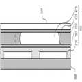
도 3 및 도 4를 참조하여 실시예 1에 따른 광 경로 조절 장치를 설명한다. 도 3은 실시예 1에 따른 광 경로 조절 장치의 모습을 나타내는 단면도이고, 도 4는 실시예 1에 따른 광 경로 조절 장치의 작동 모습을 나타내는 단면도이다.An optical path adjusting apparatus according to
광 경로 조절 장치(10)에는 한 쌍의 전극(15)이 구비된다. 전극(15)은 전기습윤 현상을 위한 전극으로서 이용된다. 전극(15)은 빛을 통과시키기 위하여 투명한 재질로 형성된다. 한 쌍의 전극(15)은 베이스 레이어(30) 상에 구비된다. 베이스 레이어(30)는 글라스 웨이퍼와 같은 투명성 재질로 형성될 수 있다. 한편, 한 쌍의 전극(15)은 후술할 극성 투명 액체의 이동 방향을 조절하기 위한 것으로서, 방향이 일치하는 한 각 전극(15)이 다수의 전극으로 분할되어 구비될 수도 있다. 즉, 서로 대립되는 방향으로 배열되는 한 전극은 다수의 전극으로 이루어진 어레이로 구비되는 것도 가능하다.The optical path control
제1 소수성 레이어(14)는 한 쌍의 전극(15) 중 어느 하나의 전극에 전력이 공급되는 경우 전력이 공급된 해당 전극에 대응하는 부분의 성질이 소수성이 감소하고 친수성이 증가하는 방향으로 변경된다. 제1 소수성 레이어(14)와 한 쌍의 전극(15)은 이격되거나 사이에 절연 물질 또는 유전체가 개재되어 절연되도록 하는 것이 바람직하다.When the first
제1 소수성 레이어(14)와 제2 소수성 레이어(11) 사이에는 불투명한 비극성 유체(13)와, 투명한 극성 액체(12)가 구비된다. 불투명한 비극성 유체(13)는 제1 소수성 레이어(14)와 제2 소수성 레이어(11) 사이에 구비되어 있으며, 투명한 극성 액체(12)는 제1 소수성 레이어(14)와 제2 소수성 레이어(11)의 사이 및 불투명한 비극성 유체(13) 내에 구비된다. 불투명한 비극성 유체(13; 액체 또는 기체)는 빛을 흡수하여 빛의 투과를 저지하는 기능을 하게 되며, 투명한 극성 액체(12)는 불투명한 비극성 유체(13)와 섞이지 않는 상태로 존재하면서 일정한 양의 빛을 투과시키는 기능을 수행한다. 또한 투명한 극성 액체(12)는 앞서 설명한 바와 같이 전력이 공급되는 전극(15)에 의하여 제1 소수성 레이어(15)의 일부가 친수성으로 변환되는 경우 해당 부분과의 접촉 면적을 증가시키는 방향으로 이동하게 된다. 이와 같이 불투명한 비극성 유체(13)와 투명한 극성 액체(12)는 조리개로서 기능하며, 별도의 전력 제어부(미도시)를 통하여 한 쌍의 전극(15) 중 어느 하나의 전극에 전력을 공급함으로써 도 4에 도시된 바와 같이 투명 극성 액체(12)가 해당 전극 측 방향으로 이동함으로써 조리개의 중심이 이동하는 것과 같은 효과를 얻을 수 있다.An opaque
그라운드 레이어(31)는 한 쌍의 전극(15)과 함께 전력이 공급되어 전기장을 형성한다. 그라운드 레이어(31)는 한 쌍의 전극(15) 사이에 구비된 그라운드 전극(31a)으로 대체되는 것도 가능하다. 이하에서는 각 상황에 맞도록 그라운드 레이어(31) 또는 그라운드 전극(31a)를 구비하여 전기장을 형성하는 것을 가정한다.The
본 실시예에 따른 광 경로 조절장치는 조리개 등 영상 촬영장치와 같은 영상 입출력 장치의 일부로서 사용될 수 도 있고, 별도의 광 결로를 조절하기 위한 장치로서도 이용이 가능하다.
The optical path control apparatus according to the present embodiment may be used as part of an image input / output device such as an image photographing apparatus such as an aperture, or may be used as a device for adjusting an additional optical condensation.
<실시예 2><Example 2>
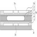
도 5 및 도 6을 참조하여 실시예 2에 따른 광 경로 조절 장치를 설명한다. 도 5는 실시예 2에 따른 광 경로 조절 장치의 모습을 나타내는 단면도이고, 도 6은 실시예 2에 따른 광 경로 조절 장치의 작동 모습을 나타내는 단면도이다.An optical path adjusting apparatus according to
도 5에 도시된 바와 같이 실시예 2에 따른 광 경로 조절 장치는 상하부에 각각 한 쌍의 전극이 구비된다는 점에서 실시예 1과 차이가 있다. 즉, 실시예 2에 따른 조리개(10a)는 제2 소수성 레이어의 상부에 추가적인 한 쌍의 전극(15a)를 더 구비한다. 이 때 상하부의 전극들은 배열되는 방향이 일치하도록 구비되는 것이 바람직하다. 제2 소수성 레이어(11)와의 사이에 절연 물질이나 유전체가 개재될 수 있음은 실시예 1과 동일하다.As shown in FIG. 5, the optical path adjusting apparatus according to the second embodiment is different from the first embodiment in that a pair of electrodes is provided at the upper and lower portions thereof. That is, the
한편, 본 실시예에서는 추가적인 한 쌍의 전극쌍(15a, 15)의 사이에는 각각그라운드 전극(31b, 31a)이 구비될 수 있다.Meanwhile, in the present embodiment,
전력의 공급은 조리개(10a)의 중심을 기준으로 동일한 방향에 위치한 전극에만 전력이 공급되도록 한다. 즉, 하부 전극 쌍 중 우측의 전극에 전력이 공급되는 경우에는 상부의 전극 쌍 중에도 우측의 전극에 전력이 공급되도록 하여야 한다. 이 경우 도 6에 도시된 바와 같이 제1 소수성 레이어(14)와 제2 소수성 레이어(11)의 우측이 친수성이 증가하는 방향으로 변환되어 극성 투명 액체(12)가 우측으로 이동하게 된다.
The supply of power allows power to be supplied only to electrodes positioned in the same direction with respect to the center of the
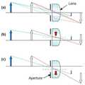
한편, 입체영상의 원리를 도 7 및 도 8을 참조하여 설명하면 다음과 같다. 도 7은 상이 맺히는 원리를 설명하기 위한 개요도이고, 도 8은 렌즈와 조리개의 이송으로 인한 상의 위치 변화를 설명하기 위한 개요도이다.Meanwhile, the principle of a stereoscopic image will be described with reference to FIGS. 7 and 8. FIG. 7 is a schematic diagram for explaining a principle of forming an image, and FIG. 8 is a schematic diagram for explaining a positional change of an image due to the transfer of a lens and an aperture.
도 7을 참조하여 설명하면, 기하 광학의 원리에 의해 렌즈의 중심을 지나는 광선(Light ray2)은 일직선을 유지하고 조리개에 의해 제한된 광선(Light ray1, Light ray3)이 렌즈 중심부에서 굴절된다. 조리개에 의하여 제한된 광선(Light ray1, Light ray3)이 굴절되어 렌즈의 중심을 지나는 광선(Light ray2)와 서로 만나는 지점에 상이 맺히게 된다.Referring to FIG. 7, the
이 때 조리개와 렌즈가 함께 이동하는 것을 가정해 보면 도 8과 같다. 즉, 도 8의 (a)와 같이 일정한 거리에 상이 맺히는 경우, 조리개와 렌즈가 상부로 이동하게 되면, 도 8의 (b)와 같이 맺히는 상 또는 상부로 이동하게 되고, 반대로 조리개와 렌즈가 아래로 이동하는 경우에는 도 8의 (c)와 같이 맺히는 상 또한 아래로 이동하게 된다. 즉, 조리개와 렌즈가 이동하는 경우에는 복수개의 카메라를 이용하여 다른 위치에서 촬영한 것과 동일한 효과를 얻을 수 있다.In this case, assume that the aperture and the lens move together as shown in FIG. 8. That is, when the image is formed at a predetermined distance as shown in (a) of FIG. 8, when the diaphragm and the lens are moved upward, the image and the upper part are moved as shown in FIG. 8 (b). In the case of moving to, the phase formed as shown in FIG. 8C also moves downward. In other words, when the iris and the lens move, the same effects as those taken at different positions using a plurality of cameras can be obtained.
한편, 앞서 설명한 바와 같이 입체 영상의 제작을 위해서는 좌안과 우안에 제공되어야 할 영상은 가상의 시야각을 제공하기 위하여 일정한 평면상에서 일정한 거리가 떨어진 별도의 영상으로 제작하여야 한다. 일반적으로 두 대의 카메라를 이용하여 이러한 입체 영상용 화면을 촬영하지만, 조리개와 렌즈의 중심을 이동시키는 경우에는 하나의 카메라를 이용하여 이러한 입체 영상을 제작할 수 있음을 알 수 있다.
Meanwhile, as described above, in order to produce a stereoscopic image, an image to be provided to the left eye and the right eye should be produced as a separate image at a constant distance from a predetermined plane in order to provide a virtual viewing angle. Generally, such a stereoscopic image is photographed using two cameras. However, when the aperture and the center of the lens are moved, it can be seen that one stereoscopic image can be produced using one camera.
<실시예 3><Example 3>
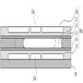
도 9 내지 도 11을 참조하여 실시예 3에 따른 광학 입출력 장치를 설명한다. 도 9는 실시예 3에 따른 광학 입출력 장치의 모습을 나타내는 단면도이고, 도 10은 실시예 3에 따른 광학 입출력 장치의 작동 모습을 나타내는 단면도이며, 도 11은 실시예 3에 따른 광학 입출력 장치에 의한 상의 위치 변화를 설명하기 위한 단면도이다.9 to 11, an optical input / output device according to a third embodiment will be described. FIG. 9 is a cross-sectional view illustrating an optical input / output device according to a third embodiment, FIG. 10 is a cross-sectional view illustrating an optical input / output device according to a third embodiment, and FIG. 11 is a cross-sectional view illustrating an optical input / output device according to a third embodiment. It is sectional drawing for demonstrating the position change of a phase.
실시예 3에 다른 광학 입출력 장치는 앞서 설명한 바와 같이 조리개와 렌즈의 이동에 의하여 입체영상을 촬영하기 위한 장치이다. 본 실시예에 따른 광학 입출력 장치는 크게 조리개(10)와 렌즈(20)로 구분될 수 있다.As described above, the optical input / output device according to the third embodiment is a device for capturing stereoscopic images by moving the aperture and the lens. The optical input / output device according to the present embodiment may be largely divided into an
조리개(10)는 앞서 설명한 실시예 1에 따른 조리개(10)와 동일한 구성부들을 구비한다. 즉, 제1 한 쌍의 전극(15)은 베이스 레이어(30)의 일면에 구비되고, 제1 소수성 레이어(14)는 제1 한 쌍의 전극(15) 상에 구비된다. 제1 소수성 레이어(14)는 제1 한 쌍의 전극(15) 중 어느 하나에 전력이 공급되는 경우 전력이 공급된 전극에 대응하는 부분의 특성이 친수성으로 변환된다. 실시예 1과 마찬가지로 제2 소수성 레이어(11)와 제1 소수성 레이어(14) 사이에는 불투명 비극성 유체(13)와 투명 극성 액체(12)가 구비되어 있다. 제1 한 쌍의 전극(15) 중 어느 하나에 전력이 공급되어 제1 소수성 레이어(15) 중 전력이 공급된 전극에 대응하는 부분이 친수성으로 변환되면, 친수성으로 변환된 부분과 투명 극성 액체(12)와의 접촉면적은 증가된다.The
한편, 렌즈부(20)를 설명한다. 렌즈부(20)는 도 9에 도시된 바와 같이 베이스 레이어(30)를 기준으로 그 하부에 구비된 제2 한 쌍의 전극(25), 제3 소수성 레이어(24), 투명 비극성 유체(22) 및 투명 극성 액체(23)를 포함한다. 베이스 레이어(30)의 타측 면에는 제2 한 쌍의 전극(25)이 구비된다. 제2 한 쌍의 전극(25)의 하부에는 제3 소수성 레이어(24)가 구비된다. 제3 소수성 레이어(24)의 하부에는 투명 비극성 유체(22)와 투명 극성 액체(23)가 구비된다. 투명 극성 액체(23)는 비극성 유체(22)의 내측에 구비되며, 제3 소수성 레이어(24)에 접촉한 상태로 구비된다. 한편, 제2 소수성 레이어(11)의 외측 면에는 글래스(glass) 재질의 그라운드 레이어가 더 구비될 수 있다. 그라운드 레이어(31)는 글래스(glass)재질의 웨이퍼 등을 이용하여 형성할 수 있다. 이외의 외부 하우징 등 본 발명의 기술적 특징과 관련이 적은 구성부들에 대한 설명은 생략한다.On the other hand, the
실시예 3에 따른 입체 영상 촬영장치를 작동시키기 위하여 제1 한 쌍의 전극(15)와 제2 한 쌍의 전극(25)에 전력을 공급한다. 이 때 조리개(10)와 렌즈(20)가 동일한 방향으로 이동될 수 있도록 동일한 방향에 위치한 전극들에 전력을 공급하는 것이 바람직하다. 즉, 제1 한 쌍의 전극(15) 중 우측의 전극에 전력이 공급되는 경우 제2 한 쌍의 전극(15) 중 우측의 전극에 전력이 공급되도록 함으로써, 도 10에 도시된 바와 같이 조리개(10)의 투명 극성 액체(12)와 렌즈(20)의 투명 극성 액체(23)가 함께 우측으로 이동하도록 제어할 수 있다.In order to operate the stereoscopic imaging apparatus according to the third embodiment, power is supplied to the first pair of
앞서 설명한 바와 같이 조리개 및 렌즈를 함께 이동시킴으로써 특정 물체에 대한 상의 위치를 변경시킬 수 있다. 즉, 도 11에 도시된 바와 같이 본 실시예에 따른 광학 입출력 장치(도 11의 (a))의 조리개(Ap) 및 렌즈(L)를 렌즈중심(Ct)으로 부터 도면 상 위로 움직이도록 제어(도 11의 (b))하여 상의 위치도 위로 움직이도록 제어할 수 있으며, 반대로 조리개 및 렌즈를 도면 상 아래로 움직이도록 제어(도 11의 (c))하여 상의 위치 또한 아래로 움직이도록 제어할 수 있다. 이러한 제어를 번갈아 함으로써 두 대의 카메라로 다른 위치에서 촬영한 것과 같은 효과를 얻을 수 있다.
As described above, the position of the image with respect to a specific object may be changed by moving the iris and the lens together. That is, as shown in FIG. 11, the aperture Ap and the lens L of the optical input / output device (FIG. 11 (a)) according to the present embodiment are controlled to move upward from the lens center Ct on the drawing. (B)) of FIG. 11 may control the position of the image to move up, and conversely, the aperture and the lens may be controlled to move down on the drawing (FIG. have. By alternating these controls, you get the same effect as shooting with two cameras at different locations.
<실시예 4><Example 4>
도 12를 참조하여 실시예 4에 따른 광학 입출력 장치를 설명한다. 도 12는 실시예 4에 따른 광학 입출력 장치의 모습을 나타내는 단면도이다.An optical input / output device according to a fourth embodiment will be described with reference to FIG. 12. 12 is a sectional view showing a state of an optical input / output device according to a fourth embodiment.
실시예 4에 따른 광학 입출력 장치는 실시예 3에 따른 광학 입출력 장치와 비교하여 보면, 전극이 한 쌍만 구비된 것에 차이가 있다. 즉, 실시예 3의 경우 조리개 및 렌즈를 제어하기 위하여 각각 한 쌍의 전극씩을 구비하고 있으나, 본 실시예에서는 조리개(10) 및 렌즈(20)를 제어하기 위한 한 쌍의 전극(15)과 한 쌍의 전극(15)과의 사이에 전기장을 형서아기 위한 그라운드 전극(15b) 만을 구비하고 있다.Compared to the optical input / output device according to the third embodiment, the optical input / output device according to the fourth embodiment has a difference in that only one pair of electrodes is provided. That is, in the third embodiment, a pair of electrodes is provided to control the diaphragm and the lens, respectively, but in the present embodiment, the pair of
즉, 한 쌍의 전극(15) 중 어느 한 전극에 전력을 공급함으로써 조리개(10)와 렌즈(20)를 동시에 제어할 수 있다. 본 실시예의 경우 조리개(10) 및 렌즈(20) 각각을 정밀하게 조절하기 어려운 면은 있으나, 더욱 간단한 구조를 갖게 됨으로써 제작 비용 및 효율이 더 좋은 장점이 있다.
That is, the
<실시예 5><Example 5>
도 13을 참조하여 실시예 5에 따른 광학 입출력 장치를 설명한다. 도 13는 실시예 5에 따른 광학 입출력 장치의 모습을 나타내는 단면도이다.An optical input / output device according to a fifth embodiment will be described with reference to FIG. 13. FIG. 13 is a sectional view showing a state of an optical input / output device according to a fifth embodiment. FIG.
실시예 5에 따른 광학 입출력 장치는 실시예 3에 따른 광학 입출력 장치에 비하여 조리개(10a)를 제어하기 위한 제3 한 쌍의 전극(15a)을 추가적으로 구비하는 것에 차이가 있다. 즉, 실시예 2에서 설명한 바와 같이 추가적인 전극 쌍을 구비함으로써 조리개(10a) 중 투명 극성 액체(12)의 제어를 보다 정밀하게 할 수 있는 장점이 있다.The optical input / output device according to the fifth embodiment is different from the optical input / output device according to the third embodiment in that it further includes a third pair of
이 경우 제1 내지 제3 한 쌍의 전극(15, 15a, 25) 중 동일한 방향에 구비된 전극들에 전력을 함께 구비함으로써 조리개(10a) 및 렌즈(20)를 동일한 방향으로 움직이도록 제어할 수 있다.
In this case, by providing electric power to electrodes provided in the same direction among the first to third pairs of
이상 본 발명의 바람직한 실시예에 대하여 설명하였으나, 본 발명의 기술적 사상이 상술한 바람직한 실시예에 한정되는 것은 아니며, 특허청구범위에 구체화된 본 발명의 기술적 사상을 벗어나지 않는 범주에서 다양한 전기습윤 현상을 이용한 광 경로 조절 장치 및 이를 구비하는 광학 입출력 장치로 구현될 수 있다.Although the preferred embodiments of the present invention have been described above, the technical idea of the present invention is not limited to the above-described preferred embodiments, and various electrowetting phenomena are not limited to the technical idea of the present invention specified in the claims. It can be implemented by the optical path control device and the optical input-output device having the same.
10: 조리개11: 제2 소수성 레이어
12: 투명 극성 액체13: 불투명 비극성 유체
14: 제1 소수성 레이어15, 15a, 25: 한 쌍의 전극
20: 유체 렌즈22: 투명 비극성 유체
23: 투명 극성 액체10: aperture 11: second hydrophobic layer
12: transparent polar liquid 13: opaque nonpolar fluid
14: first
20: fluid lens 22: transparent nonpolar fluid
23: transparent polar liquid
Claims (16)
Translated fromKorean불투명 비극성 유체 및 상기 불투명 비극성 유체 내에 구비되는 투명 극성 액체를 포함하되,
상기 전극에 인가되는 전원에 응답하여 상기 투명 극성 유체의 위치가 가변되는 광 경로 조절 장치.At least one electrode;
An opaque nonpolar fluid and a transparent polar liquid provided in the opaque nonpolar fluid,
And a position of the transparent polar fluid in response to a power applied to the electrode.
상기 전극 상에 구비되고, 상기 전극에 전력이 공급되는 경우 전력이 공급된 전극의 위치에 대응하는 부분의 특성이 친수성으로 변환되는 제1 소수성 레이어;를 포함하는 광 경로 조절 장치.The method of claim 1,
And a first hydrophobic layer provided on the electrode and configured to convert the characteristic of the portion corresponding to the position of the powered electrode into hydrophilicity when the electrode is supplied with power.
상기 전극은 제1 복수의 전극들로 구비되고,
상기 제1 복수의 전극들 중 어느 하나의 전극에만 전력이 공급되도록 제어하여 상기 투명 극성 액체를 전력이 공급된 전극 측으로 이동시키는 전력 제어부를 포함하는 전기습윤 현상을 이용한 광 경로 조절 장치.3. The method of claim 2,
The electrode is provided with a first plurality of electrodes,
And a power controller for controlling power to be supplied to only one of the first plurality of electrodes to move the transparent polar liquid toward the powered electrode.
상기 제1 소수성 레이어와 평행하게 구비되는 제2 소수성 레이어; 및
상기 제2 소수성 레이어의 외측에 구비되는 제2 복수의 전극들을 포함하는 전기습윤 현상을 이용한 광 경로 조절 장치.3. The method of claim 2,
A second hydrophobic layer provided in parallel with the first hydrophobic layer; And
Optical path control apparatus using an electrowetting phenomenon comprising a second plurality of electrodes provided on the outside of the second hydrophobic layer.
상기 제1 복수의 전극들은 각각 상기 제2 복수의 전극들의 위치와 대응하도록 쌍을 이루어 구비되고,
상기 제1 복수의 전극들과 상기 제2 복수의 전극들 중 어느 하나의 전극 쌍에만 전력을 공급하여 상기 투명 극성 액체를 전력이 공급된 전극 쌍 측으로 이동시키는 전력 제어부를 구비하는 전기습윤 현상을 이용한 광 경로 조절 장치.5. The method of claim 4,
The first plurality of electrodes are provided in pairs to correspond to the positions of the second plurality of electrodes, respectively,
Using an electrowetting phenomenon comprising a power control unit for supplying power to only one electrode pair of the first plurality of electrodes and the second plurality of electrodes to move the transparent polar liquid toward the pair of powered electrodes. Optical path control device.
상기 제1 복수의 전극들과 상기 제1 소수성 레이어 사이, 그리고 상기 제2 복수의 전극들과 상기 제2 소수성 레이어 사이에는 절연층이 더 구비되는 전기습윤 현상을 이용한 광 경로 조절 장치.5. The method of claim 4,
And an insulating layer is further provided between the first plurality of electrodes and the first hydrophobic layer and between the second plurality of electrodes and the second hydrophobic layer.
상기 베이스 레이어의 일면에 구비되는 제1 전극 및 제2 전극;
상기 제1 전극 및 제2 전극 상에 구비되고, 상기 제1 전극 및 제2 전극에 전력이 공급되는 경우 대응하는 위치의 특성이 친수성으로 변환되는 제1 소수성 레이어;
상기 제1 소수성 레이어와 평행하게 구비되는 제2 소수성 레이어;
상기 제1 소수성 레이어와 상기 제2 소수성 레이어 사이에 구비되는 불투명 비극성 유체와 상기 불투명성 액체 내에 구비되는 투명 극성 액체를 포함하는 유체 조리개;
상기 베이스 레이어의 타측면에 구비되는 제3 전극 및 제4 전극;
상기 제3 전극 및 제4 전극 상에 구비되고, 상기 제3 전극 및 제4 전극에 전력이 공급되는 경우 전력이 공급된 전극의 위치에 대응하는 부분의 특성이 친수성으로 변환되는 제3 소수성 레이어; 및
상기 제3 소수성 레이어의 타측면에 구비되고, 투명 비극성 유체와 상기 투명 비극성 유체 내에 구비되는 투명 극성 액체를 포함하는 유체 렌즈;를 포함하는 전기습윤 현상을 이용한 광학 입출력 장치.Transparency base layer;
First and second electrodes provided on one surface of the base layer;
A first hydrophobic layer provided on the first electrode and the second electrode and converting characteristics of a corresponding position into hydrophilicity when electric power is supplied to the first electrode and the second electrode;
A second hydrophobic layer provided in parallel with the first hydrophobic layer;
A fluid diaphragm including an opaque nonpolar fluid provided between the first hydrophobic layer and the second hydrophobic layer and a transparent polar liquid provided in the opaque liquid;
Third and fourth electrodes provided on the other side of the base layer;
A third hydrophobic layer provided on the third electrode and the fourth electrode and converting the characteristic of the portion corresponding to the position of the powered electrode when the power is supplied to the third electrode and the fourth electrode into hydrophilicity; And
And a fluid lens provided on the other side of the third hydrophobic layer, the fluid lens including a transparent nonpolar fluid and a transparent polar liquid provided in the transparent nonpolar fluid.
상기 제1 전극 및 상기 제3 전극 쌍과, 상기 제2 전극 및 상기 제4 전극 쌍 중 어느 하나의 전극 쌍에만 전력이 공급되도록 제어하여 상기 유체 조리개와 상기 유체 렌즈의 투명 극성 액체들을 전력이 공급된 전극 쌍 측으로 이동시키는 전력 제어부를 포함하는 전기습윤 현상을 이용한 광학 입출력 장치.The method according to claim 6,
Power is supplied to only the first electrode and the third electrode pair and only one electrode pair of the second electrode and the fourth electrode pair to supply the transparent polar liquids of the fluid stop and the fluid lens. Optical input and output device using the electrowetting phenomenon comprising a power control unit for moving to the electrode pair side.
상기 제2 소수성 레이어의 외측에는 상기 제1 전극의 위치에 대응하는 제5 전극 및 상기 제2 전극의 위치에 대응하는 제6 전극이 구비되는 전기습윤 현상을 이용한 광학 입출력 장치.The method according to claim 6,
An optical input / output device using an electrowetting phenomenon, wherein a fifth electrode corresponding to a position of the first electrode and a sixth electrode corresponding to a position of the second electrode are provided outside the second hydrophobic layer.
상기 제1 전극, 상기 제3 전극 및 상기 제5 전극으로 이루어진 전극 군과, 상기 제2 전극, 상기 제4 전극 및 상기 제6 전극으로 이루어진 전극 군 중 어느 하나의 전극 군에만 전력이 공급되도록 제어하여 상기 유체 조리개와 상기 유체 렌즈의 투명 극성 액체들을 전력이 공급된 전극 군 측으로 이동시키는 전력 제어부를 포함하는 전기습윤 현상을 이용한 광학 입출력 장치.9. The method of claim 8,
Control so that electric power is supplied to only one electrode group of the electrode group consisting of the first electrode, the third electrode, and the fifth electrode, and the electrode group consisting of the second electrode, the fourth electrode, and the sixth electrode. And a power control unit for moving the fluid stop and the transparent polar liquids of the fluid lens toward the electrode group.
상기 제2 소수성 레이어의 외측 면에는 글래스 재질의 그라운드 레이어가 더 구비되는 전기습윤 현상을 이용한 광학 입출력 장치.The method according to claim 6,
An optical input / output device using an electrowetting phenomenon, wherein a ground layer of glass is further provided on an outer surface of the second hydrophobic layer.
상기 제1 전극 및 상기 제2 전극은 각각 복수개의 전극 어레이로 형성되는 전기습윤 현상을 이용한 광학 입출력 장치.The method according to claim 6,
And the first electrode and the second electrode are each formed of a plurality of electrode arrays.
상기 제1 전극 및 제2 전극 상에 구비되고, 상기 제1 전극 및 제2 전극에 전력이 공급되는 경우 대응하는 위치의 특성이 친수성으로 변환되는 제1 소수성 레이어;
상기 제1 소수성 레이어와 평행하게 구비되는 제2 소수성 레이어;
상기 제1 소수성 레이어와 상기 제2 소수성 레이어 사이에 구비되는 불투명 비극성 유체와 상기 불투명성 액체 내에 구비되는 투명 극성 액체를 포함하는 유체 조리개;
상기 제1 전극 및 상기 제2 전극을 기준으로 상기 제1 소수성 레이어의 타측에 구비되고, 상기 제1 전극 및 상기 제2 전극에 전력이 공급되는 경우 전력이 공급된 전극의 위치에 대응하는 부분의 특성이 친수성으로 변환되는 제3 소수성 레이어; 및
상기 제3 소수성 레이어의 타측면에 구비되고, 투명 비극성 유체와 상기 투명 비극성 유체 내에 구비되는 투명 극성 액체를 포함하는 유체 렌즈;를 포함하는 전기습윤 현상을 이용한 광학 입출력 장치.A first electrode and a second electrode;
A first hydrophobic layer provided on the first electrode and the second electrode and converting characteristics of a corresponding position into hydrophilicity when electric power is supplied to the first electrode and the second electrode;
A second hydrophobic layer provided in parallel with the first hydrophobic layer;
A fluid diaphragm including an opaque nonpolar fluid provided between the first hydrophobic layer and the second hydrophobic layer and a transparent polar liquid provided in the opaque liquid;
A portion provided on the other side of the first hydrophobic layer with respect to the first electrode and the second electrode, and corresponding to a position of an electrode to which power is supplied when power is supplied to the first electrode and the second electrode; A third hydrophobic layer, wherein the property is converted to hydrophilic; And
And a fluid lens provided on the other side of the third hydrophobic layer, the fluid lens including a transparent nonpolar fluid and a transparent polar liquid provided in the transparent nonpolar fluid.
상기 제1 전극과, 상기 제2 전극 중 어느 하나의 전극에만 전력이 공급되도록 제어하여 상기 유체 조리개와 상기 유체 렌즈의 투명 극성 액체들을 전력이 공급된 전극측으로 이동시키는 전력 제어부를 포함하는 전기습윤 현상을 이용한 광학 입출력 장치.The method of claim 12,
An electrowetting phenomenon including a power control unit for controlling power to be supplied to only one of the first electrode and the second electrode to move the transparent polar liquids of the fluid stop and the fluid lens toward the powered electrode side Optical input and output device using.
상기 제2 소수성 레이어의 외측에는 상기 제1 전극의 위치에 대응하는 제3 전극 및 상기 제2 전극의 위치에 대응하는 제4 전극이 구비되는 전기습윤 현상을 이용한 광학 입출력 장치.The method of claim 12,
An optical input / output device using an electrowetting phenomenon, wherein a third electrode corresponding to a position of the first electrode and a fourth electrode corresponding to a position of the second electrode are provided outside the second hydrophobic layer.
상기 제1 전극 및 상기 제3 전극 쌍과, 상기 제2 전극 및 상기 제4 전극 쌍 중 어느 하나의 전극 쌍에만 전력이 공급되도록 제어하여 상기 유체 조리개와 상기 유체 렌즈의 투명 극성 액체들을 전력이 공급된 전극 쌍 측으로 이동시키는 전력 제어부를 포함하는 전기습윤 현상을 이용한 광학 입출력 장치.
15. The method of claim 14,
Power is supplied to only the first electrode and the third electrode pair and only one electrode pair of the second electrode and the fourth electrode pair to supply the transparent polar liquids of the fluid stop and the fluid lens. Optical input and output device using the electrowetting phenomenon comprising a power control unit for moving to the electrode pair side.
Priority Applications (1)
| Application Number | Priority Date | Filing Date | Title |
|---|---|---|---|
| KR1020120075582AKR101559193B1 (en) | 2012-07-11 | 2012-07-11 | The control of light path using an electrowetting principle and its apparatus |
Applications Claiming Priority (1)
| Application Number | Priority Date | Filing Date | Title |
|---|---|---|---|
| KR1020120075582AKR101559193B1 (en) | 2012-07-11 | 2012-07-11 | The control of light path using an electrowetting principle and its apparatus |
Related Child Applications (1)
| Application Number | Title | Priority Date | Filing Date |
|---|---|---|---|
| KR1020140160107ADivisionKR20140146566A (en) | 2014-11-17 | 2014-11-17 | The control of light path using an electrowetting principle and its apparatus |
Publications (2)
| Publication Number | Publication Date |
|---|---|
| KR20140008699Atrue KR20140008699A (en) | 2014-01-22 |
| KR101559193B1 KR101559193B1 (en) | 2015-10-12 |
Family
ID=50142376
Family Applications (1)
| Application Number | Title | Priority Date | Filing Date |
|---|---|---|---|
| KR1020120075582AExpired - Fee RelatedKR101559193B1 (en) | 2012-07-11 | 2012-07-11 | The control of light path using an electrowetting principle and its apparatus |
Country Status (1)
| Country | Link |
|---|---|
| KR (1) | KR101559193B1 (en) |
Cited By (2)
| Publication number | Priority date | Publication date | Assignee | Title |
|---|---|---|---|---|
| KR20190015911A (en)* | 2017-08-07 | 2019-02-15 | 명지대학교 산학협력단 | Tunable liquid shutter based on electrowetting actuation |
| WO2019177220A1 (en)* | 2018-03-16 | 2019-09-19 | 엘지전자 주식회사 | Liquid iris, optical device comprising same, and mobile terminal |
Families Citing this family (1)
| Publication number | Priority date | Publication date | Assignee | Title |
|---|---|---|---|---|
| TW202011055A (en) | 2018-05-22 | 2020-03-16 | 美商康寧公司 | Methods of manufacturing liquid lenses |
- 2012
- 2012-07-11KRKR1020120075582Apatent/KR101559193B1/ennot_activeExpired - Fee Related
Cited By (5)
| Publication number | Priority date | Publication date | Assignee | Title |
|---|---|---|---|---|
| KR20190015911A (en)* | 2017-08-07 | 2019-02-15 | 명지대학교 산학협력단 | Tunable liquid shutter based on electrowetting actuation |
| WO2019177220A1 (en)* | 2018-03-16 | 2019-09-19 | 엘지전자 주식회사 | Liquid iris, optical device comprising same, and mobile terminal |
| US11350025B2 (en) | 2018-03-16 | 2022-05-31 | Lg Electronics Inc. | Optical device and mobile terminal comprising same |
| US11418696B2 (en) | 2018-03-16 | 2022-08-16 | Lg Electronics Inc. | Optical device |
| US11528405B2 (en) | 2018-03-16 | 2022-12-13 | Lg Electronics Inc. | Optical device and mobile terminal |
Also Published As
| Publication number | Publication date |
|---|---|
| KR101559193B1 (en) | 2015-10-12 |
Similar Documents
| Publication | Publication Date | Title |
|---|---|---|
| CN102722022B (en) | Image display system | |
| KR101911439B1 (en) | Micro-lens capable of changing focal length, micro-lens array comprising the same, 3D display comprising micro-lens array and method of operating 3D display | |
| US8369018B2 (en) | Spatial image display device | |
| JP2017003981A (en) | Display device and method of operating display device | |
| WO2018072514A1 (en) | Display device and image display method | |
| TWI498598B (en) | Autostereoscopic projection device and display apparatus comprising thereof | |
| CN103809228A (en) | Electrowetting lens array, 3D image display device and 3D image pickup device | |
| US20120002023A1 (en) | Spatial image display device | |
| KR102208960B1 (en) | Holographic display | |
| WO2017221722A1 (en) | Liquid lens and method for driving same, imaging device, and display device | |
| US9042028B2 (en) | Electrowetting prism device and multi-view 3D image display apparatus including the same | |
| TW201221998A (en) | Liquid optical element array and display | |
| KR20130028579A (en) | Zoom lens module and endoscope system | |
| US11882263B2 (en) | ToF camera | |
| KR20140146566A (en) | The control of light path using an electrowetting principle and its apparatus | |
| Shahini et al. | Toward individually tunable compound eyes with transparent graphene electrode | |
| CN105700145A (en) | Head-mounted image display device | |
| KR101559193B1 (en) | The control of light path using an electrowetting principle and its apparatus | |
| CN204188912U (en) | The face battle array electrically-controlled liquid crystal light driving control based on two-way voltage signal disperses microtrabeculae mirror chip | |
| CN111045210B (en) | Near-to-eye display device | |
| CN110850585A (en) | Display panel, device and method, electrowetting microcavity unit and light control substrate | |
| CN104317078B (en) | Area array electronically-controlled liquid crystal light-diverging micro-cylinder chip based on dual voltage signal drive control | |
| TWI513999B (en) | Stereoscopic microscope system | |
| Pätz et al. | Imaging systems with aspherically tunable micro-optical elements | |
| JP2013156581A (en) | Optical element and display device |
Legal Events
| Date | Code | Title | Description |
|---|---|---|---|
| A201 | Request for examination | ||
| PA0109 | Patent application | St.27 status event code:A-0-1-A10-A12-nap-PA0109 | |
| PA0201 | Request for examination | St.27 status event code:A-1-2-D10-D11-exm-PA0201 | |
| P11-X000 | Amendment of application requested | St.27 status event code:A-2-2-P10-P11-nap-X000 | |
| P13-X000 | Application amended | St.27 status event code:A-2-2-P10-P13-nap-X000 | |
| R15-X000 | Change to inventor requested | St.27 status event code:A-3-3-R10-R15-oth-X000 | |
| R16-X000 | Change to inventor recorded | St.27 status event code:A-3-3-R10-R16-oth-X000 | |
| E902 | Notification of reason for refusal | ||
| PE0902 | Notice of grounds for rejection | St.27 status event code:A-1-2-D10-D21-exm-PE0902 | |
| T11-X000 | Administrative time limit extension requested | St.27 status event code:U-3-3-T10-T11-oth-X000 | |
| E13-X000 | Pre-grant limitation requested | St.27 status event code:A-2-3-E10-E13-lim-X000 | |
| P11-X000 | Amendment of application requested | St.27 status event code:A-2-2-P10-P11-nap-X000 | |
| P13-X000 | Application amended | St.27 status event code:A-2-2-P10-P13-nap-X000 | |
| E902 | Notification of reason for refusal | ||
| PE0902 | Notice of grounds for rejection | St.27 status event code:A-1-2-D10-D21-exm-PE0902 | |
| PG1501 | Laying open of application | St.27 status event code:A-1-1-Q10-Q12-nap-PG1501 | |
| T11-X000 | Administrative time limit extension requested | St.27 status event code:U-3-3-T10-T11-oth-X000 | |
| T11-X000 | Administrative time limit extension requested | St.27 status event code:U-3-3-T10-T11-oth-X000 | |
| E13-X000 | Pre-grant limitation requested | St.27 status event code:A-2-3-E10-E13-lim-X000 | |
| P11-X000 | Amendment of application requested | St.27 status event code:A-2-2-P10-P11-nap-X000 | |
| P13-X000 | Application amended | St.27 status event code:A-2-2-P10-P13-nap-X000 | |
| E601 | Decision to refuse application | ||
| PE0601 | Decision on rejection of patent | St.27 status event code:N-2-6-B10-B15-exm-PE0601 | |
| T11-X000 | Administrative time limit extension requested | St.27 status event code:U-3-3-T10-T11-oth-X000 | |
| A107 | Divisional application of patent | ||
| J201 | Request for trial against refusal decision | ||
| PA0107 | Divisional application | St.27 status event code:A-0-1-A10-A18-div-PA0107 St.27 status event code:A-0-1-A10-A16-div-PA0107 | |
| PJ0201 | Trial against decision of rejection | St.27 status event code:A-3-3-V10-V11-apl-PJ0201 | |
| J301 | Trial decision | Free format text:TRIAL DECISION FOR APPEAL AGAINST DECISION TO DECLINE REFUSAL REQUESTED 20141117 Effective date:20150824 | |
| PJ1301 | Trial decision | St.27 status event code:A-3-3-V10-V15-crt-PJ1301 Decision date:20150824 Appeal event data comment text:Appeal Kind Category : Appeal against decision to decline refusal, Appeal Ground Text : 2012 0075582 Appeal request date:20141117 Appellate body name:Patent Examination Board Decision authority category:Office appeal board Decision identifier:2014101007071 | |
| PS0901 | Examination by remand of revocation | St.27 status event code:A-6-3-E10-E12-rex-PS0901 | |
| S901 | Examination by remand of revocation | ||
| GRNO | Decision to grant (after opposition) | ||
| PS0701 | Decision of registration after remand of revocation | St.27 status event code:A-3-4-F10-F13-rex-PS0701 | |
| GRNT | Written decision to grant | ||
| PR0701 | Registration of establishment | St.27 status event code:A-2-4-F10-F11-exm-PR0701 | |
| PR1002 | Payment of registration fee | St.27 status event code:A-2-2-U10-U11-oth-PR1002 Fee payment year number:1 | |
| PG1601 | Publication of registration | St.27 status event code:A-4-4-Q10-Q13-nap-PG1601 | |
| P22-X000 | Classification modified | St.27 status event code:A-4-4-P10-P22-nap-X000 | |
| FPAY | Annual fee payment | Payment date:20181004 Year of fee payment:4 | |
| PR1001 | Payment of annual fee | St.27 status event code:A-4-4-U10-U11-oth-PR1001 Fee payment year number:4 | |
| P22-X000 | Classification modified | St.27 status event code:A-4-4-P10-P22-nap-X000 | |
| R18-X000 | Changes to party contact information recorded | St.27 status event code:A-5-5-R10-R18-oth-X000 | |
| PC1903 | Unpaid annual fee | St.27 status event code:A-4-4-U10-U13-oth-PC1903 Not in force date:20191003 Payment event data comment text:Termination Category : DEFAULT_OF_REGISTRATION_FEE | |
| PN2301 | Change of applicant | St.27 status event code:A-5-5-R10-R13-asn-PN2301 St.27 status event code:A-5-5-R10-R11-asn-PN2301 | |
| PC1903 | Unpaid annual fee | St.27 status event code:N-4-6-H10-H13-oth-PC1903 Ip right cessation event data comment text:Termination Category : DEFAULT_OF_REGISTRATION_FEE Not in force date:20191003 | |
| R18-X000 | Changes to party contact information recorded | St.27 status event code:A-5-5-R10-R18-oth-X000 |