KR20130140811A - Indicator for knife location in a stapling or vessel sealing instrument - Google Patents
Indicator for knife location in a stapling or vessel sealing instrumentDownload PDFInfo
- Publication number
- KR20130140811A KR20130140811AKR1020137017201AKR20137017201AKR20130140811AKR 20130140811 AKR20130140811 AKR 20130140811AKR 1020137017201 AKR1020137017201 AKR 1020137017201AKR 20137017201 AKR20137017201 AKR 20137017201AKR 20130140811 AKR20130140811 AKR 20130140811A
- Authority
- KR
- South Korea
- Prior art keywords
- knife
- cutting
- tool
- cut
- image
- Prior art date
- Legal status (The legal status is an assumption and is not a legal conclusion. Google has not performed a legal analysis and makes no representation as to the accuracy of the status listed.)
- Granted
Links
Images


Classifications
- A—HUMAN NECESSITIES
- A61—MEDICAL OR VETERINARY SCIENCE; HYGIENE
- A61B—DIAGNOSIS; SURGERY; IDENTIFICATION
- A61B34/00—Computer-aided surgery; Manipulators or robots specially adapted for use in surgery
- A61B34/20—Surgical navigation systems; Devices for tracking or guiding surgical instruments, e.g. for frameless stereotaxis
- A—HUMAN NECESSITIES
- A61—MEDICAL OR VETERINARY SCIENCE; HYGIENE
- A61B—DIAGNOSIS; SURGERY; IDENTIFICATION
- A61B17/00—Surgical instruments, devices or methods
- A61B17/068—Surgical staplers, e.g. containing multiple staples or clamps
- A61B17/072—Surgical staplers, e.g. containing multiple staples or clamps for applying a row of staples in a single action, e.g. the staples being applied simultaneously
- A—HUMAN NECESSITIES
- A61—MEDICAL OR VETERINARY SCIENCE; HYGIENE
- A61B—DIAGNOSIS; SURGERY; IDENTIFICATION
- A61B18/00—Surgical instruments, devices or methods for transferring non-mechanical forms of energy to or from the body
- A61B18/04—Surgical instruments, devices or methods for transferring non-mechanical forms of energy to or from the body by heating
- A61B18/12—Surgical instruments, devices or methods for transferring non-mechanical forms of energy to or from the body by heating by passing a current through the tissue to be heated, e.g. high-frequency current
- A61B18/14—Probes or electrodes therefor
- A61B18/1442—Probes having pivoting end effectors, e.g. forceps
- A61B18/1445—Probes having pivoting end effectors, e.g. forceps at the distal end of a shaft, e.g. forceps or scissors at the end of a rigid rod
- A—HUMAN NECESSITIES
- A61—MEDICAL OR VETERINARY SCIENCE; HYGIENE
- A61B—DIAGNOSIS; SURGERY; IDENTIFICATION
- A61B18/00—Surgical instruments, devices or methods for transferring non-mechanical forms of energy to or from the body
- A61B18/04—Surgical instruments, devices or methods for transferring non-mechanical forms of energy to or from the body by heating
- A61B18/12—Surgical instruments, devices or methods for transferring non-mechanical forms of energy to or from the body by heating by passing a current through the tissue to be heated, e.g. high-frequency current
- A61B18/14—Probes or electrodes therefor
- A61B18/1482—Probes or electrodes therefor having a long rigid shaft for accessing the inner body transcutaneously in minimal invasive surgery, e.g. laparoscopy
- A—HUMAN NECESSITIES
- A61—MEDICAL OR VETERINARY SCIENCE; HYGIENE
- A61B—DIAGNOSIS; SURGERY; IDENTIFICATION
- A61B34/00—Computer-aided surgery; Manipulators or robots specially adapted for use in surgery
- A61B34/30—Surgical robots
- A—HUMAN NECESSITIES
- A61—MEDICAL OR VETERINARY SCIENCE; HYGIENE
- A61B—DIAGNOSIS; SURGERY; IDENTIFICATION
- A61B90/00—Instruments, implements or accessories specially adapted for surgery or diagnosis and not covered by any of the groups A61B1/00 - A61B50/00, e.g. for luxation treatment or for protecting wound edges
- A61B90/36—Image-producing devices or illumination devices not otherwise provided for
- A61B90/37—Surgical systems with images on a monitor during operation
- A—HUMAN NECESSITIES
- A61—MEDICAL OR VETERINARY SCIENCE; HYGIENE
- A61B—DIAGNOSIS; SURGERY; IDENTIFICATION
- A61B17/00—Surgical instruments, devices or methods
- A61B2017/00017—Electrical control of surgical instruments
- A61B2017/00022—Sensing or detecting at the treatment site
- A—HUMAN NECESSITIES
- A61—MEDICAL OR VETERINARY SCIENCE; HYGIENE
- A61B—DIAGNOSIS; SURGERY; IDENTIFICATION
- A61B17/00—Surgical instruments, devices or methods
- A61B2017/00017—Electrical control of surgical instruments
- A61B2017/00115—Electrical control of surgical instruments with audible or visual output
- A61B2017/00119—Electrical control of surgical instruments with audible or visual output alarm; indicating an abnormal situation
- A—HUMAN NECESSITIES
- A61—MEDICAL OR VETERINARY SCIENCE; HYGIENE
- A61B—DIAGNOSIS; SURGERY; IDENTIFICATION
- A61B17/00—Surgical instruments, devices or methods
- A61B2017/00367—Details of actuation of instruments, e.g. relations between pushing buttons, or the like, and activation of the tool, working tip, or the like
- A61B2017/00398—Details of actuation of instruments, e.g. relations between pushing buttons, or the like, and activation of the tool, working tip, or the like using powered actuators, e.g. stepper motors, solenoids
- A—HUMAN NECESSITIES
- A61—MEDICAL OR VETERINARY SCIENCE; HYGIENE
- A61B—DIAGNOSIS; SURGERY; IDENTIFICATION
- A61B17/00—Surgical instruments, devices or methods
- A61B17/068—Surgical staplers, e.g. containing multiple staples or clamps
- A61B17/072—Surgical staplers, e.g. containing multiple staples or clamps for applying a row of staples in a single action, e.g. the staples being applied simultaneously
- A61B2017/07214—Stapler heads
- A61B2017/07285—Stapler heads characterised by its cutter
- A—HUMAN NECESSITIES
- A61—MEDICAL OR VETERINARY SCIENCE; HYGIENE
- A61B—DIAGNOSIS; SURGERY; IDENTIFICATION
- A61B18/00—Surgical instruments, devices or methods for transferring non-mechanical forms of energy to or from the body
- A61B2018/00571—Surgical instruments, devices or methods for transferring non-mechanical forms of energy to or from the body for achieving a particular surgical effect
- A61B2018/00607—Coagulation and cutting with the same instrument
- A—HUMAN NECESSITIES
- A61—MEDICAL OR VETERINARY SCIENCE; HYGIENE
- A61B—DIAGNOSIS; SURGERY; IDENTIFICATION
- A61B18/00—Surgical instruments, devices or methods for transferring non-mechanical forms of energy to or from the body
- A61B18/04—Surgical instruments, devices or methods for transferring non-mechanical forms of energy to or from the body by heating
- A61B18/12—Surgical instruments, devices or methods for transferring non-mechanical forms of energy to or from the body by heating by passing a current through the tissue to be heated, e.g. high-frequency current
- A61B18/14—Probes or electrodes therefor
- A61B18/1442—Probes having pivoting end effectors, e.g. forceps
- A61B2018/1452—Probes having pivoting end effectors, e.g. forceps including means for cutting
- A61B2018/1455—Probes having pivoting end effectors, e.g. forceps including means for cutting having a moving blade for cutting tissue grasped by the jaws
- A—HUMAN NECESSITIES
- A61—MEDICAL OR VETERINARY SCIENCE; HYGIENE
- A61B—DIAGNOSIS; SURGERY; IDENTIFICATION
- A61B34/00—Computer-aided surgery; Manipulators or robots specially adapted for use in surgery
- A61B34/20—Surgical navigation systems; Devices for tracking or guiding surgical instruments, e.g. for frameless stereotaxis
- A61B2034/2046—Tracking techniques
- A61B2034/2051—Electromagnetic tracking systems
- A—HUMAN NECESSITIES
- A61—MEDICAL OR VETERINARY SCIENCE; HYGIENE
- A61B—DIAGNOSIS; SURGERY; IDENTIFICATION
- A61B34/00—Computer-aided surgery; Manipulators or robots specially adapted for use in surgery
- A61B34/20—Surgical navigation systems; Devices for tracking or guiding surgical instruments, e.g. for frameless stereotaxis
- A61B2034/2046—Tracking techniques
- A61B2034/2059—Mechanical position encoders
- A—HUMAN NECESSITIES
- A61—MEDICAL OR VETERINARY SCIENCE; HYGIENE
- A61B—DIAGNOSIS; SURGERY; IDENTIFICATION
- A61B90/00—Instruments, implements or accessories specially adapted for surgery or diagnosis and not covered by any of the groups A61B1/00 - A61B50/00, e.g. for luxation treatment or for protecting wound edges
- A61B90/08—Accessories or related features not otherwise provided for
- A61B2090/0803—Counting the number of times an instrument is used
- A—HUMAN NECESSITIES
- A61—MEDICAL OR VETERINARY SCIENCE; HYGIENE
- A61B—DIAGNOSIS; SURGERY; IDENTIFICATION
- A61B90/00—Instruments, implements or accessories specially adapted for surgery or diagnosis and not covered by any of the groups A61B1/00 - A61B50/00, e.g. for luxation treatment or for protecting wound edges
- A61B90/90—Identification means for patients or instruments, e.g. tags
- A61B90/98—Identification means for patients or instruments, e.g. tags using electromagnetic means, e.g. transponders
Landscapes
- Health & Medical Sciences (AREA)
- Surgery (AREA)
- Life Sciences & Earth Sciences (AREA)
- Engineering & Computer Science (AREA)
- Nuclear Medicine, Radiotherapy & Molecular Imaging (AREA)
- Animal Behavior & Ethology (AREA)
- Public Health (AREA)
- Veterinary Medicine (AREA)
- Biomedical Technology (AREA)
- Heart & Thoracic Surgery (AREA)
- Medical Informatics (AREA)
- Molecular Biology (AREA)
- General Health & Medical Sciences (AREA)
- Physics & Mathematics (AREA)
- Robotics (AREA)
- Otolaryngology (AREA)
- Plasma & Fusion (AREA)
- Oral & Maxillofacial Surgery (AREA)
- Pathology (AREA)
- Electromagnetism (AREA)
- Gynecology & Obstetrics (AREA)
- Radiology & Medical Imaging (AREA)
- Surgical Instruments (AREA)
- Manipulator (AREA)
Abstract
Translated fromKorean
Description
Translated fromKorean관련 출원의 상호 참조Cross Reference of Related Application
본 출원은 2011년 2월 15일 제출된 미국 가 특허출원 제61/443,115호의 정식 출원으로서 그 우선권을 주장하며, 이것의 전체 내용은 본원에 참고자료로 포함된다.This application claims the priority as a formal application of US Provisional Patent Application No. 61 / 443,115, filed February 15, 2011, the entire contents of which are incorporated herein by reference.
본 출원은 2010년 2월 12일 제출된 미국출원 제12/705,418호, 발명의 명칭 "Cut and Seal Instrument"(대리인 사건번호 No. ISRG02180/US); 2009년 3월 31일 제출된 미국출원 제12/415,332호(대리인 사건번호 No. ISRG01510/US); 및 2006년 6월 29일 제출된 미국출원 제11/478,531호(대리인 사건번호 No. ISRG0010/US)와 관련되며, 이들의 전문이 본원에 참고자료로 포함된다.This application is incorporated by reference in US application Ser. No. 12 / 705,418, filed Feb. 12, 2010, entitled "Cut and Seal Instrument" (agent no. ISRG02180 / US); US Application No. 12 / 415,332, filed March 31, 2009 (Agent Case No. ISRG01510 / US); And US Application No. 11 / 478,531 filed on June 29, 2006, Representative Event No. ISRG0010 / US, the entirety of which is incorporated herein by reference.
로봇 수술 시스템에 의해 수행되는 최소 침습 수술이 알려져 있는데, 이것은 직접적으로 수술을 수행할 수 없는 사람에게 유익한 경우의 임상 과정에서 통상 사용된다. 이러한 시스템의 일례는 공동 소유의 미국특허 제7,155,315호, 발명의 명칭 "Camera Referenced Control in a Minimally Invasive Surgical Apparatus"에서 설명된 최소 침습 로봇 수술 시스템이다.Minimally invasive surgery performed by a robotic surgical system is known, which is commonly used in clinical procedures where it is beneficial to a person who cannot perform the surgery directly. One example of such a system is the minimally invasive robotic surgical system described in commonly owned US Pat. No. 7,155,315, entitled “Camera Referenced Control in a Minimally Invasive Surgical Apparatus”.
최소 침습 수술의 통상적 형태는 내시경이다. 최소 침습 의료 기술에서 내시경 수술 기구는 일반적으로 수술 부위를 보기 위한 내시경과 말단 작동기를 한정하는 작업 도구를 포함한다. 전형적인 수술용 말단 작동기는, 예를 들어 클램프, 그래스퍼, 가위, 조직 절단기, 스테이플러, 또는 니들 홀더를 포함한다. 작업 도구는 종래의 (개방) 수술에서 사용되는 것들과 유사한데, 단 각 도구의 말단 작동기는, 예를 들어 대략 12인치 길이의 기다란 튜브의 단부에 지지된다. 말단 작동기를 조작하기 위해서 사람 오퍼레이터, 전형적으로 의사는 주 조작기를 조작하거나, 아니면 명령을 내린다. 주 조작기로부터의 명령은 적절히 번역되어 종속 조작기로 전송된다. 다음에, 종속 조작기는 사용자의 명령에 따라서 말단 작동기를 조작한다. 의사는 말단 작동기의 움직임에서 다소 떨어져 있으므로 일반적으로 의사는 내시경 영상과 같은 피드백 메커니즘에 의존해서 환자의 몸안에서 수술 도구의 위치를 결정한다. 일반적으로 원격수술 시스템에서는 의사에게 "내부 사용자 인터페이스"가 제공된다. 이 내부 사용자 인터페이스는 수술 동안 의사가 볼 수 있는 디스플레이를 포함한다.A common form of minimally invasive surgery is endoscopy. In minimally invasive medical technology, endoscopic surgical instruments generally include a work tool that defines an endoscope and distal actuator for viewing the surgical site. Typical surgical end actuators include, for example, clamps, grasper, scissors, tissue cutters, staplers, or needle holders. The working tools are similar to those used in conventional (open) surgery, except that the end actuators of each tool are supported, for example, at the ends of elongated tubes approximately 12 inches long. To operate the end actuator, the human operator, typically the physician, operates or commands the main manipulator. Commands from the main manipulator are properly translated and sent to the subordinate manipulators. The slave manipulator then operates the end actuator according to the user's command. Since the physician is somewhat distant from the distal actuator movement, the physician typically relies on feedback mechanisms such as endoscopy to determine the position of the surgical tool within the patient's body. In general, a telesurgical system provides a physician with an "internal user interface." This internal user interface includes a display that can be seen by the doctor during surgery.
최소 침습 수술에서 수행되는 과정들 중 조직의 절제가 있는데, 이것은 신체 조직의 클램핑, 실링 및 절단을 포함할 수 있다. 조직 실링 및 절단 과정에서 말단 작동기는 조직을 실링하기 위한 메커니즘(예를 들어, RF 에너지, 봉합실, 스테이플 등)과 절단 부재(예를 들어, 조직 절단기, 블레이드, 절제 에너지)를 구비한다. 전형적으로, 실링 및 절단 과정은 조직을 클램핑하는 단계, 클램핑된 조직을 절단선의 어느 한쪽에서 실링하는 단계, 다음에 절단선을 따라 클램핑된 조직을 절단하는 단계를 수반한다. 어떤 이유로든 절단 과정이 지체되거나 실패한다면 절단 부재가 노출된 위치에 그대로 남을 수 있으므로 위험하게 될 수 있다. 이 위치에서 절단 부재를 지닌 말단 작동기의 제거는 해당 장치에 인접한 다른 조직을 의도치 않게 절단할 수 있거나, 또는 도구가 제거된 후에는 의사나 다른 수술 요원들이 위험하게 될 수 있다. 절단 실패가 발생하는 경우는 적고, 절단 요소를 보는 의사의 시야가 말단 작동기에 의해 가려질 수 있으므로 의사는 절단 요소가 어떻게 위치되고 이동되는지에 대한 정확한 심성 모형을 유지할 수 없고, 노출된 절단 요소에 의해 제기되는 위험을 인식할 수 없다.Among the procedures performed in minimally invasive surgery is resection of tissue, which may include clamping, sealing and cutting of body tissue. In tissue sealing and cutting, the end effector includes a mechanism for sealing tissue (eg, RF energy, sutures, staples, etc.) and a cutting member (eg, tissue cutter, blade, ablation energy). Typically, the sealing and cutting process involves clamping the tissue, sealing the clamped tissue on either side of the cutting line, and then cutting the clamped tissue along the cutting line. If the cutting process is delayed or fails for any reason, it can be dangerous as the cutting member may remain in the exposed position. Removal of the end effector with the cutting member in this position can inadvertently cut other tissue adjacent to the device, or can be dangerous to doctors or other surgical personnel after the tool is removed. Cutting failures are less likely, and the physician's view of the cutting elements may be obscured by the distal actuator, so the physician cannot maintain an accurate mental model of how the cutting elements are positioned and moved, The risks raised by them are not recognized.
의사가 수술 동안 조직 절단기의 위치 및 장소를 시각화하고, 더 중요하게는 이 위치 및 장소에 따라 습관적으로 대응할 수 있게 허용하는 표시 및 영상을 제공하는 시스템 및 방법이 바람직할 것이다. 이러한 방법은 의사가 조직 절단기를 어떻게 작동시킬 것인지 직관적인 "감각"을 개발하여 절단을 수월하게 하고, 잠재적인 조직 손상을 방지할 수 있게 할 것이다.It would be desirable to have a system and method that provides indications and images that allow the physician to visualize the location and location of the tissue cutter during surgery and, more importantly, habitually respond to this location and location. This method will allow the surgeon to develop an intuitive “sense” of how to operate the tissue cutter, to facilitate cutting and to prevent potential tissue damage.
말단 작동기의 도구의 위치를 표시하기 위한 개선된 시스템 및 방법이 제공된다. 청구된 방법 및 시스템은 사용자 인터페이스 상에 물질을 클램핑하는 모터-구동 도구의 영상을 표시하는 것에 관한 것으로서, 상기 도구는 물질을 클램핑하기 위한 제1 및 제2 쥬(jaw)와 물질을 절단하기 위한 절단 요소(예를 들어, 나이프 또는 블레이드)를 구비하며, 사용자 인터페이스 상에 겹쳐서 절단 요소의 위치에 대한 시각적 표시자를 표시한다. 절단 요소(예를 들어, 블레이드, 나이프)는 다양한 위치를 포함하며, 여기서 위치는 절단 요소의 위치 및/또는 배향을 나타낸다. 많은 구체예에서, 도구는 제1 및 제2 쥬와 말단 작동기 내에 배치된 나이프를 구비한 말단 작동기를 포함하며, 나이프는 쥬들의 장축을 따라 절단 전 위치에서 절단 완료 위치까지 이동할 수 있도록 배치되고, 이로써 쥬들 사이에 클램핑된 조직이 절단된다. 나이프 위치는 절단 전 위치, 절단 완료 위치, 절단 미완료 위치, 및 노출된 위치 중 어느 것 또는 전부를 포함할 수 있다. 설명된 방법은 나이프가 물질 또는 말단 작동기의 쥬들의 방해로 인해서 보이지 않을 수 있는 경우에도 사용자가 말단 작동기의 나이프의 위치 및/또는 배향을 시각화하거나 감지할 수 있게 하며, 이것은 최소 침습 로봇 수술 과정에서 특히 유용하다. 상기 방법 및 시스템은 의사가 절단 동안 나이프의 움직임에 따라 습관적으로 대응할 수 있어서 해당 과정에서 의사의 직관적인 감각을 개선할 수 있기 때문에 유익하다. 이것은 나이프가 "노출된" 또는 "절단 미완료" 위치에 있는 상태에서 나이프의 움직임이 지체되는 드문 경우에 특히 유용한데, 이때는 의사가 위험을 인지하지 못한다면 잠재적으로 의도치 않은 조직 손상을 일으킬 수 있기 때문이다. 본원에 개시된 다양한 구체예는 주로 수술 용도와 관련하여 설명되지만, 이들 수술 용도는 단지 예를 든 용도일 뿐으로서, 개시된 말단 작동기, 도구 및 방법은 인체 내외부는 물론 비수술적 용도를 포함하는 다른 적합한 용도들에서도 사용될 수 있다.Improved systems and methods are provided for indicating the position of the tool of the end actuator. The claimed method and system relate to displaying an image of a motor-driven tool for clamping a material on a user interface, the tool for first and second jaws for clamping the material and for cutting the material. It has a cutting element (eg a knife or blade) and overlaps on the user interface to display a visual indicator of the position of the cutting element. Cutting elements (eg blades, knives) include various positions, where the positions indicate the position and / or orientation of the cutting elements. In many embodiments, the tool includes a distal actuator having a knife disposed within the distal actuator with the first and second juws, wherein the knife is arranged to move from the pre-cut position to the cut complete position along the long axis of the jews, This cuts the clamped tissue between the juices. The knife position may include any or all of the pre-cut position, the cut complete position, the cut incomplete position, and the exposed position. The described method allows the user to visualize or detect the position and / or orientation of the knife of the end actuator even if the knife may not be visible due to interference of the material or the jews of the end actuator. Especially useful. The method and system are beneficial because the physician can habitually respond to the movement of the knife during cutting, thereby improving the physician's intuitive sense in the process. This is particularly useful in the rare case where the knives are delayed with the knife in the "exposed" or "not cut" position, as it can potentially cause unintended tissue damage if the doctor is not aware of the danger. to be. While the various embodiments disclosed herein are primarily described in terms of surgical uses, these surgical uses are merely exemplary uses, and the disclosed end effectors, tools, and methods may be used in other suitable uses, including internally and externally, as well as non-surgical uses. Can also be used.
바람직한 구체예에서, 나이프 위치의 표시는 절단 과정 동안 및/또는 후에, 더 바람직하게는 절단 과정 내내 디스플레이 상에 중첩된다. 상기 표시는 사용자에게 나이프의 위치를 전달하기에 충분한 어떠한 시각적 표시자를 포함할 수 있다. 나이프 위치는 단부 작동기 상에서 나이프의 위치 및/또는 나이프의 배향을 더 포함할 수 있다. 이상적으로, 나이프 위치의 표시자는 말단 작동기 상에서 실제 나이프 위치 및 배향에 상응하는 위치에서 말단 작동기의 영상에 겹쳐진 나이프의 합성된 표식을 포함한다.In a preferred embodiment, the indication of the knife position is superimposed on the display during and / or after the cutting process, more preferably throughout the cutting process. The indication may include any visual indicator sufficient to convey the position of the knife to the user. The knife position may further comprise the position of the knife and / or the orientation of the knife on the end actuator. Ideally, the indicator of knife position comprises a composite marker of the knife superimposed on the image of the end actuator at a position corresponding to the actual knife position and orientation on the end actuator.
한 구체예에서, 방법은 주변을 이동하는 요소를 추적하는 단계, 및 상기 요소의 위치 표시자를 사용자 인터페이스 상에 표시하는 단계를 포함하며, 여기서 상기 요소의 적어도 일부분은 과정 동안 사용자 인터페이스 상에 표시된 주변 영상에서 시야에서 가려져 있다. 시야에서 가려진 상기 요소의 일부분은 해당 과정 동안 다른 때에는 보일 수 있다. 추가로, 시야에서 가려진 상기 요소의 일부분은 해당 과정 동안 바뀔 수 있는데, 예를 들어 상기 요소가 주변을 이동하거나, 또는 주변에 있는 눈에 보이는 조직이나 다른 도구 성분이 상기 요소에 대해 이동하거나 하면 그렇게 된다. 요소를 추적하는 단계는 상기 요소의 위치 또는 배향을 결정하는 단계를 포함할 수 있으며, 이것은 주로 요소에 이동 가능하게 연결된 도구에 대해 결정된다. 많은 구체예에서, 상기 요소는 최소 침습 수술 과정에서와 같이, 환자의 체강에 삽입된 도구에 연결된 환자의 신체 조직을 절단하기 위한 절단 블레이드를 포함한다. 요소를 추적하는 단계는 상기 요소를 움직이는 메커니즘을 추적하거나 또는 상기 요소 상에 배치된 위치 마커의 영상을 가공하는 단계를 포함할 수 있다. 요소의 위치 표시자가 사용자 인터페이스 상에 표시될 수 있으며, 이로써 상기 요소가 복수의 위치 사이를 이동할 때 사용자는 위치에 따라 습관적으로 대응할 수 있다. 일부 구체예에서, 위치 표시자는 요소가 제1 위치와 제2 위치 사이에서 예상치 않게 중단되었을 때 상기 요소가 중단되었음의 표시와 같은, 트리거 상태에 반응해서 대체 표시를 제공할 수 있다. 사용자 인터페이스 상에 표시자를 표시하는 단계는 주변 및/또는 도구의 비디오 영상에 나타난 요소의 합성 표식과 같은, 디스플레이 상에 상기 요소의 표식을 표시하는 단계를 포함할 수 있다. 바람직하게, 위치 표시자는 동적 표시자로서, 상기 표시자가 요소의 동작을 전달해서 사용자가 과정 동안 요소의 움직임을 보고 그에 익숙해질 수 있게 한다.In one embodiment, a method includes tracking an element moving around, and displaying a location indicator of the element on a user interface, wherein at least a portion of the element is displayed on the user interface during the process. It is hidden from view in the image. A portion of the element that is hidden in view may be visible at other times during the process. In addition, a portion of the element that is obscured in the field of view may change during the process, for example if the element moves around, or if visible tissue or other tool components around it move relative to the element. do. Tracking an element may include determining the position or orientation of the element, which is primarily determined for a tool movably connected to the element. In many embodiments, the element includes a cutting blade for cutting the body tissue of the patient connected to a tool inserted in the body cavity of the patient, such as in a minimally invasive surgical procedure. Tracking an element may include tracking a mechanism for moving the element or processing an image of a location marker disposed on the element. The position indicator of the element may be displayed on the user interface, thereby allowing the user to habitually respond to the position as the element moves between a plurality of positions. In some embodiments, the position indicator can provide an alternate indication in response to a trigger condition, such as an indication that the element has stopped when the element unexpectedly stopped between the first and second positions. Displaying an indicator on the user interface may include displaying the marker of the element on a display, such as a composite marker of the element shown in a video image of the periphery and / or the tool. Preferably, the location indicator is a dynamic indicator, which communicates the movement of the element so that the user can see and become familiar with the movement of the element during the process.
많은 구체예에서, 방법 및 시스템은 도구의 제1 쥬와 제2 쥬 사이에 조직을 클램핑하는 단계, 및 조직을 클램핑하라는 사용자 명령에 반응해서 도구의 모터에 동력을 제공하는 단계를 포함하며, 상기 모터는 나이프에 작동 가능하게 연결되어 절단 전 나이프 위치와 절단 완료 나이프 위치 사이에서 나이프를 쥬에 대해 움직일 수 있고, 이로써 조직이 절단된다. 전형적으로, 나이프는 적어도 부분적으로 쥬들 사이에 배치되므로 도구의 쥬들은 해당 과정 동안 도구의 영상에서 움직이는 나이프의 시야를 방해할 수 있다. 클램핑 및 절단은 전형적으로 절단하거나 클램핑하라는 사용자 명령에 반응해서 일어나지만, 절단은 또한 성공적인 클램핑 후 자동적으로 일어날 수도 있다. 전형적으로, 조직이 클램핑되고, 이후 절단선의 어느 한쪽에서 실링된 다음에, 절단선을 따라 조직이 절단된다.In many embodiments, the methods and systems include clamping tissue between the first and second jugs of the tool, and powering the motor of the tool in response to a user command to clamp the tissue, wherein The motor is operably connected to the knife to move the knife relative to the jug between the pre-cut knife position and the cut complete knife position, thereby cutting tissue. Typically, the knife is placed at least partially between the jugs so that the tools' jews can obstruct the view of the moving knife in the image of the tool during the process. Clamping and cutting typically occur in response to a user command to cut or clamp, but cutting may also occur automatically after successful clamping. Typically, the tissue is clamped, then sealed on either side of the cut line, and then the tissue is cut along the cut line.
한 구체예에서, 방법 및 시스템은 나이프가 노출된 상태에서 나이프의 움직임이 지체될 때와 같이, 절단 과정 동안 및/또는 후에 사용자 인터페이스 상에 나이프 위치의 경고 표시를 중첩시키는 단계를 포함할 수 있다. 상기 경고는 나이프 위치에 대한 상기 설명된 표시와 별도의 표시일 수 있으며, 이로써 사용자에게 절단 과정의 지체 또는 실패에 의해 야기될 수 있는 위험한 상태를 통지할 수 있다. 예를 들어, 디스플레이는 절단 과정 동안 나이프 지체에 반응해서 나이프가 지체되거나 노출되었을 때 빛나는 경고등을 포함할 수 있다.In an embodiment, the method and system can include superimposing a warning indication of the knife position on the user interface during and / or after the cutting process, such as when the knife's movement is retarded with the knife exposed. . The warning may be a separate indication from the above described indication of knife position, thereby informing the user of a dangerous condition which may be caused by delay or failure of the cutting process. For example, the display may include a warning light that glows when the knife is delayed or exposed in response to the knife delay during the cutting process.
한 구체예에서, 시스템은 이동하는 요소, 사용자 인터페이스 디스플레이 및 상기 요소와 상기 사용자 인터페이스 디스플레이를 연결하는 프로세서를 포함하며, 상기 프로세서는 디스플레이 상에 상기 요소의 위치에 대한 시각적 표시자를 출력할 수 있다. 많은 구체예에서, 시스템은 상기 요소에 이동 가능하게 연결된 도구 및 비디오 카메라와 같은 영상 캡처 장치를 더 포함한다. 프로세서 및/또는 영상 캡처 장치를 사용해서 도구에 대한 상기 요소의 위치 및 배향을 측정할 수 있으며, 또는 그 반대로도 측정할 수 있다. 상기 요소는 주로 도구 상에서 복수의 위치들 사이에서, 바람직하게는 제1 위치와 제2 위치 사이에서 이동할 수 있다. 많은 구체예에서, 시스템은 프로세서에 의해서 얻어진 위치 정보(예를 들어, 영상 캡처 장치로부터의 영상)를 가공해서 요소와 도구의 상대적 위치를 결정한다. 프로세서는 요소의 움직임을 행하는 메커니즘에 연결될 수 있으며, 이로써 상기 요소 또는 도구의 위치가 메커니즘의 변위로부터 프로세서에 의해서 결정될 수 있다.In one embodiment, the system includes a moving element, a user interface display and a processor connecting the element with the user interface display, the processor may output a visual indicator of the position of the element on the display. In many embodiments, the system further includes an image capture device such as a video camera and a tool movably connected to the element. A processor and / or image capture device may be used to measure the position and orientation of the element relative to the tool, or vice versa. The element can mainly move between a plurality of positions on the tool, preferably between a first position and a second position. In many embodiments, the system processes positional information obtained by a processor (eg, an image from an image capture device) to determine the relative position of the element and the tool. The processor may be coupled to a mechanism that performs the movement of the element so that the position of the element or tool may be determined by the processor from the displacement of the mechanism.
많은 구체예에서, 도구는 물질을 클램핑하기 위한 쥬들 및 클램핑된 물질을 절단하기 위한 절단 요소(예를 들어, 나이프 또는 블레이드)를 구비한 말단 작동기를 포함한다. 전형적으로, 도구는 조직을 클램핑하기 위한 쥬들 및 클램핑된 조직을 절단하기 위한 나이프를 구비한 수술 도구이다. 나이프는 절단 전 위치에서 절단 완료 위치까지 쥬들 사이에서 이동하도록 구성되며, 이로써 쥬들 사이에 클램핑된 조직이 절단된다. 절단 전 위치와 절단 완료 위치에서는 나이프의 절단 엣지가 말단 작동기 내에 안전하게 배치되어 인접한 조직을 보호할 수 있다. 나이프는 절단 전 위치와 절단 완료 위치 사이에 추가의 나이프 위치를 포함할 수 있으며, 제한은 아니지만 "나이프 노출된" 위치 및 "절단 미완료" 위치를 포함한다. 나이프 위치는 말단 작동기에 대한 나이프의 위치 및/또는 배향을 더 포함할 수 있다.In many embodiments, the tool includes end actuators with a jus for clamping the material and a cutting element (eg, a knife or blade) for cutting the clamped material. Typically, the tool is a surgical tool with jiles for clamping tissue and a knife for cutting the clamped tissue. The knife is configured to move between the juices from the pre-cut position to the cut complete position, thereby cutting the clamped tissue between the jews. In the pre-cut and cut complete positions, the cutting edge of the knife can be securely placed in the end actuator to protect adjacent tissue. The knife may include additional knife positions between the pre-cut position and the cut complete position, including but not limited to "knife exposed" positions and "uncut" positions. The knife position may further comprise the position and / or orientation of the knife relative to the end actuator.
많은 구체예에서, 사용자 인터페이스 디스플레이는 영상 캡처 장치 및 프로세서와 연결되어 도구의 말단 작동기의 영상과 나이프 위치의 표시를 표시할 수 있다. 어떤 이유로든 도구가 보이지 않는다면 사용자는 도구의 영상 위에 중첩된 나이프의 위치 표시자 및 표식을 볼 수 있을 것이다. 바람직한 구체예에서, 나이프 위치의 표시자는 말단 작동기의 실제 또는 합성된 영상 위에 중첩된 나이프의 합성 표식을 포함한다. 또한, 디스플레이는 나이프의 지체된 형상 또는 노출된 절단 엣지와 같은, 나이프가 지체되어 위험이 제기되었다는 나이프 위치의 표시자와 별도의 경고를 표시할 수 있다.In many embodiments, the user interface display can be coupled with an image capture device and a processor to display an image of the knife position and an image of the end actuator of the tool. If the tool is not visible for any reason, the user will be able to see the position markers and markers of the knife overlaid on the image of the tool. In a preferred embodiment, the indicator of knife position comprises a composite marker of the knife overlaid on the actual or synthesized image of the end actuator. In addition, the display may display a separate warning from the indicator of the knife position that the knife has been delayed and poses a risk, such as a delayed shape of the knife or an exposed cutting edge.
본 발명의 성질 및 이점을 더 충분히 이해하기 위해 이후의 상세한 설명 및 첨부한 도면이 참조되어야 한다. 본 발명의 다른 양태, 목적 및 이점은 이후의 도면 및 상세한 설명으로부터 명백해질 것이다.Reference should be made to the following detailed description and the accompanying drawings in order to more fully understand the nature and advantages of the present invention. Other aspects, objects, and advantages of the invention will be apparent from the following figures and detailed description.
도 1은 많은 구체예에 따른, 최소 침습 원격수술 시스템을 포함하는 수술실의 상면도를 도시한다.
도 2는 도 1의 최소 침습 원격수술 시스템의 환자 카트의 정면도이다.
도 3은 도 1의 최소 침습 원격수술 시스템의 구성요소들을 나타내는 블럭도이다.
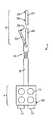
도 4는 많은 구체예에 따른, 절단 및 시일 수술 도구의 도시적 도면이다.
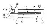
도 5는 많은 구체예에 따른, 수술 도구의 탈착 가능한 절단 및 시일 카트리지의 도식적 상면도이다.
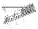
도 6은 많은 구체예에 따른, 조합된 절단 및 시일 최소 침습 수술 기구의 원단부의 투시도이다.
도 7은 많은 구체예에 따른, 나이프의 상이한 위치를 도시하는 도 6의 구체예의 측면 단면도이다.
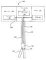
도 8은 많은 구체예에 따른, 수술 도구의 도식적 도면이다.
도 9는 많은 구체예에 따른, 시스템의 도식적 도면이다.
도 10은 많은 구체예에 따른, 나이프 위치의 표시자가 나타난 도구의 영상을 보여주는 사용자 인터페이스 디스플레이를 예시한다.
도 11은 많은 구체예에 따른, 도구 추적을 이용한 조합된 조직 절단 및 실링 시스템을 예시하는 도시적 도면이다.
도 12-13은 많은 구체예에 따른, 방법의 도식적 도해이다.1 illustrates a top view of an operating room that includes a minimally invasive telesurgical system, in accordance with many embodiments.
FIG. 2 is a front view of a patient cart of the minimally invasive telesurgical system of FIG. 1.
3 is a block diagram illustrating the components of the minimally invasive telesurgical system of FIG. 1.
4 is an illustrative view of a cutting and sealing surgical tool, in accordance with many embodiments.
5 is a schematic top view of a removable cutting and sealing cartridge of a surgical tool, in accordance with many embodiments.
6 is a perspective view of the distal end of a combined cutting and seal minimally invasive surgical instrument, in accordance with many embodiments.
7 is a side cross-sectional view of the embodiment of FIG. 6 showing different positions of the knife, in accordance with many embodiments.
8 is a schematic diagram of a surgical tool, in accordance with many embodiments.
9 is a schematic diagram of a system, in accordance with many embodiments.
10 illustrates a user interface display showing an image of a tool in which an indicator of knife position is shown, in accordance with many embodiments.
11 is an illustrative diagram illustrating a combined tissue cutting and sealing system using tool tracking, in accordance with many embodiments.
12-13 are schematic illustrations of a method, in accordance with many embodiments.
이후의 설명에서 본 발명의 다양한 구체예가 설명될 것이다. 설명의 목적을 위해서 구체적인 형상 및 상세한 내용은 구체예들의 더욱 충분한 이해를 제공하기 위해 제시된다. 그러나, 본 발명은 구체적인 상세한 설명 없이도 실시될 수 있다는 것이 당업자에게 또한 자명할 것이다. 또한, 설명된 구체예가 불명료하게 되지 않도록 잘 공지된 특징들은 생략되거나 단순화될 수 있다.In the following description various embodiments of the invention will be described. For purposes of explanation, specific shapes and details are set forth in order to provide a more sufficient understanding of the embodiments. However, it will also be apparent to one skilled in the art that the present invention may be practiced without the specific details. In addition, well known features may be omitted or simplified so that the described embodiments are not obscured.
절단 과정 동안 도구 상에서 절단 요소의 위치 및/또는 배향을 표시하기 위한 개선된 시스템 및 방법이 제공된다. 청구된 방법 및 시스템은 다른 추적 방법과 함께 사용될 수 있고, 이로써 사용자는 도구에 대한 절단 요소의 위치 또는 배향을 인지할 수 있게 된다. 이들 방법 및 시스템은 사용자가 절단 동안 절단 요소를 볼 수 없을 가능성이 있는 로봇 시스템에서 유용하며, 모터-구동 단부 작동기를 사용하는 최소 침습 수술 과정에서 특히 유용하다. 이들 방법은 말단 작동기로부터 떨어져 있는 의사가 해당 과정 동안 도구와 관련하여 절단 부재를 어떻게 이동할지에 대한 감각을 개발할 수 있게 하기 때문에 유익하다. 도구에 대한 절단 부재의 위치에 대해 감각적 표시를 생성함으로써 상기 방법은 의사가 도구 상에서 절단 부재의 위치에 익숙해질 수 있게 하며, 이로써 절단 과정이 실패했을 때 의사는 절단 부재에 의해 제기되는 잠재적 위험을 인식하게 될 것이고, 위험을 피하기 위한 적절한 행동을 취할 수 있다. 본원에 개시된 다양한 구체예는 주로 수술 용도와 관련하여 설명되지만, 이들 수술 용도는 단지 예를 든 용도일 뿐으로서, 개시된 말단 작동기, 도구 및 방법은 인체 내외부는 물론 비수술적 용도를 포함하는 다른 적합한 용도들에서도 사용될 수 있다.Improved systems and methods are provided for indicating the position and / or orientation of cutting elements on a tool during the cutting process. The claimed methods and systems can be used in conjunction with other tracking methods, allowing the user to know the position or orientation of the cutting element relative to the tool. These methods and systems are useful in robotic systems where the user is unlikely to see the cutting elements during cutting, and is particularly useful in minimally invasive surgical procedures using motor-driven end actuators. These methods are beneficial because they allow the physician away from the end effector to develop a sense of how to move the cutting member relative to the tool during the procedure. By generating a sensory indication of the position of the cutting member relative to the tool, the method allows the physician to become familiar with the position of the cutting member on the tool, thereby allowing the doctor to take the potential risks presented by the cutting member when the cutting process fails. You will be aware of it and can take appropriate action to avoid risks. While the various embodiments disclosed herein are primarily described in terms of surgical uses, these surgical uses are merely exemplary uses, and the disclosed end effectors, tools, and methods may be used in other suitable uses, including internally and externally, as well as non-surgical uses. Can also be used.
이제 도면(유사한 참조 번호는 몇몇 도면에서 유사한 부품을 나타낸다)을 참조하면, 도 1은 많은 구체예에 따른 오퍼레이터 스테이션 또는 의사 콘솔(3)을 구비한 최소 침습 원격수술 시스템(1)을 도시한다. 의사 콘솔(3)은 디스플레이(15)를 포함하며, 여기에 수술 부위의 영상이 의사(S)에게 표시된다. 알려진 대로, 지지대(미도시)가 제공되며, 양손에 각각 하나씩 2개의 주 컨트롤을 쥔 상태에서 의사(S)가 자신의 팔뚝을 그 위에 기댈 수 있다. 더 많은 말단 작동기가 이용될 경우 더 많은 컨트롤이 제공될 수 있지만, 전형적으로 의사는 한번에 단지 2개의 컨트롤만을 조작한다. 다수의 말단 작동기가 사용될 경우, 의사는 주 컨트롤에서 하나의 말단 작동기를 해제하고, 동일한 주 컨트롤로 다른 말단 작동기를 쥔다. 의사 콘솔(3)을 사용할 때, 의사(S)는 전형적으로 의사 콘솔 앞의 의자에 앉아서 자신의 눈을 디스플레이(5)의 앞에 위치시키고, 주 컨트롤을 각 손에 하나씩 쥔 상태에서 팔뚝을 지지대 위에 기댄다.Referring now to the drawings, wherein like reference numerals refer to like parts in some of the drawings, FIG. 1 shows a minimally invasive
원격수술 시스템(1)의 환자측 카트(5)는 환자(P)에 인접 위치된다. 사용시에 환자측 카트(5)는 수술이 필요한 환자(P)에 가까이 위치된다. 환자측 카트(5)는 전형적으로 수술 과정 동안 고정되며, 로봇 조립체(5A, 5B, 5C 및 5D)를 포함한다. 의사 콘솔(3)은 전형적으로 환자측 카트(5)로부터 먼 곳에 위치되며, 상당한 거리만큼, 심지어 몇 마일까지 환자측 카트로부터 분리될 수 있지만, 전형적으로는 환자측 카트와 같은 수술실 안에서 사용될 것이다. 로봇 암 조립체(5A, 5B 및 5C)는 각각 수술 기구 또는 도구(7A, 7B 및 7C)를 포함한다. 조립체(5D)는 해당 과정 동안 디스플레이 상에 도구의 영상을 나타내기 위한 내시경을 포함할 수 있다. 로봇 암 조립체(5A, 5B 및 5C)의 도구(7A, 7B 및 7C)는 각각 말단 작동기(9A, 9B 및 9C)를 포함한다. 도구(7A, 7B 및 7C)의 샤프트의 단부에 대한 말단 작동기(9A, 9B 및 9C)의 움직임도 의사 콘솔(3)의 주 컨트롤에 의해서 제어된다. 도구(7A, 7B 및 7C) 중 어느 것은 조직 절단 및 실링 기구를 포함할 수 있다. 이러한 기구는 조직을 클램핑하기 위한 쥬들, 조직을 실링하기 위한 부재(예를 들어, 스테이플링 또는 RF 메커니즘), 및 실링 후 조직을 절단하기 위한 부재를 구비한 말단 작동기를 포함할 수 있으며, 이것의 예는 도 4-7에 예시된다. 도 2는 환자 카트 및 관련된 로봇 암 조립체의 정면도를 도시한다.The
원격수술 시스템(1)은 비전 카트(11)를 포함한다. 한 구체예에서, 비전 카트(11)는 원격수술 시스템(1)을 조종하기 위한 컴퓨터 장비나 다른 컨트롤들의 대부분을 포함한다. 일례로서, 의사 콘솔(30)의 주 컨트롤러에 의해 전송된 신호는 비전 카트(11)로 전송될 수 있고, 이어서 비전 카트가 신호를 해석해서 말단 작동기(9A, 9B, 9C) 및/또는 로봇 암 조립체(5A, 5B, 5C)에 대한 명령을 생성할 수 있다. 이에 더해서, 내시경과 같은 영상 캡처 장치(5D)로부터 디스플레이(15)로 전송된 비디오가 비전 카트(11)에 의해 가공되거나, 또는 간단히 전달될 수 있다.The
도 3은 원격수술 시스템(1)의 도식적 도해이다. 볼 수 있는 대로, 시스템은 의사 콘솔(3), 환자측 카트(5) 및 비전 카트(11)를 포함한다. 또한, 한 구체예에 따라서, 추가의 컴퓨터(13)와 디스플레이(15)가 제공된다. 이들 구성요소는 의사 콘솔(3), 환자측 카트(5) 및/또는 비전 카트(11) 중 하나 이상에 통합될 수 있다. 예를 들어, 컴퓨터(82)의 특징들은 비전 카트(11)에 통합될 수 있다. 또한, 디스플레이(15)의 특징들은 의사 콘솔(3)에, 예를 들어 디스플레이(5)에 통합될 수 있거나, 또는 완전히 분리된 디스플레이나 의사 콘솔에 의해서 또는 다른 위치에 제공될 수 있다. 이에 더해서, 한 구체예에 따라서, 컴퓨터(13)는 디스플레이(15)와 같은 디스플레이 없이 이용될 수 있는 정보를 생성할 수 있다.3 is a schematic illustration of a
도 4는 본 발명의 한 양태에 따른 예시적인 절단 및 시일 수술 기구(2)의 도시적 도면이다. 도 4에 도시된 대로, 기구(2)는 근단부(환자 바깥쪽)에 힘 전달 메커니즘과 원단부(환자 안쪽; 수술 부위에 더 가깝다)에 조합된 절단 및 시일 말단 작동기(6)를 포함한다. 전달 메커니즘(4)과 절단 및 시일 말단 작동기(6)는 기구 샤프트(8)에 의해서 연결된다. 절단 및 시일 말단 작동기(6)는 선택적으로 리스트 메커니즘(10)을 통해 기구 샤프트(8)에 연결된다. 기구(2)는 전형적으로 최소 침습 수술을 수행하기 위해 사용되며, 수술 동안 말단 작동기(6)와 샤프트(8)의 원위부는 작은 절개부 또는 자연 개구부를 통해, 전형적으로 캐뉼라를 통해 환자에 삽입되어 수술 과정을 수행할 수 있다.4 is an illustrative view of an exemplary cutting and sealing
묘사된 구체예에서, 힘 전달 메커니즘(4)은 디스크(12)를 포함하며, 이것은 예를 들어 수술 로봇 시스템에서 사용하기 위해 기구(2)가 장착될 때 상응하는 서보모터(미도시)와 짝을 이룬다. 서보모터는 기구(2)의 구성요소들을 움직이기 위한 가동력을 제공한다. 4개의 디스크(12)가 도시되지만, 기구(2)의 원하는 피가동 자유도에 따라서 더 많거나 적게 사용될 수도 있다. 서보모터는 주 조작기를 움직이는 의사에 의해 제어되는데, 이것은 아래에 더 상세히 설명된다. 또한, 하나 이상의 서보모터(14, 16)가 기구(2) 자체에 장착되어 기구(2) 구성요소들에 가동력을 제공할 수 있다. 샤프트(8)는 일반적으로 중공 튜브로서, 이것을 통해서 가동 케이블이 전달 메커니즘(4)에서 기구(2)의 원단부에 있는 구성요소들까지 이어진다. 이러한 케이블은 기구 구성요소들을 움직이는 다양한 방식(예를 들어, 로드, 회전 샤프트 등)의 예시이다. 일부 구체예에서, 샤프트(8)는 회전하여 말단 작동기(6)에 롤을 제공한다. 샤프트(8) 및 말단 작동기(6)는 다양한 외경(예를 들어, 5mm, 8mm, 10mm, 12mm 등)을 가질 수 있다. 샤프트(8)는 강성인 것으로서 묘사되지만, 사용될 수 있는 다양한 가요성 구체예들도 예시된다.In the depicted embodiment, the force transmission mechanism 4 comprises a
이제, 도 4에 묘사된 구체예에서, 절단 및 시일 말단 작동기(6)는 고정된 쥬 부재(18), 이동하는 쥬 부재(20), 및 고정된 쥬 부재(18)에 탈착 가능하게 연결된 탈착 가능한 절단 및 시일 카트리지(22)를 포함한다. 절단 및 실링을 위해 조직이 쥬(18)와 쥬(20) 사이에 클램핑된다. 절단 및 시일 카트리지(22)는 이동하는 나이프(24)(예를 들어, 예리한 블레이드 또는 조직 절단기)를 포함한다. 이동하는 쥬 부재(20)는 힘 전달 메커니즘(4)을 통해 전달된 힘에 의해 가동될 수 있거나, 또는 기구(2)에 장착된 모터(14, 16) 중 하나에 의해서 가동될 수 있다. 유사하게, 나이프(24)는 힘 전달 메커니즘(4)을 통해 전달된 힘에 의해, 또는 모터(14, 16) 중 하나에 의해서 가동될 수 있다. 한 양태에서, 하나의 모터(14 또는 16)를 사용하여 쥬(20)와 나이프(24)를 모두 가동시킬 수 있다. 한 대안의 양태에서, 쥬(18)는 이동 가능할 수 있고, 쥬(20)는 고정될 수 있으며, 이로써 카트리지(22)가 기구 작동 동안 이동된다. 다른 대안의 양태에서, 양쪽 쥬(18 및 20)가 이동 가능하다.Now, in the embodiment depicted in FIG. 4, the cutting and seal
말단 작동기(6)는 또 조직 실링 능력을 포함한다. 제1 조직 실링 전극(26)은 카트리지(22)의 내부면 위에 위치된다. 제2 조직 실링 전극(28)은 전극(26)과 대향하여 쥬(20) 위에 위치된다. 전극(26, 28)은 하기 더 상세히 설명된다. 조직 실링을 위한 전기 에너지는 기구(2)의 근단부에 있는 전기적 결합부(30)를 통해 전극(26, 28)에 제공된다. 도 4에 묘사된 것과 같은 전기적 결합부(30)는 기구에 위치될 수 있는 다양한 위치를 대표하며, 조직 실링 에너지원과의 수동 결합이 필요할 수 있거나, 또는 기구(2)가 수술 작업을 위한 로봇 조작기에 장착되었을 때 에너지원과 자동적으로 결합될 수도 있다. 또는 달리, 조직 실링 능력은 스테이플링 또는 봉합에 의한 것과 같이, 다른 수단에 의해서 제공될 수 있으며, 이것은 말단 작동기에 의해 수행될 수 있다.The
도 5는 탈착 가능한 절단 및 시일 카트리지(22)의 도식적 상면도이다. 기다란 "U" 모양으로 묘사된 전극(26)이 슬롯(32)을 둘러싸고 있고, 슬롯을 통해 나이프(24)가 이동한다. 다양한 다른 전극 모양이나 형상이 사용될 수 있다. 많은 양태에서, 전극(26)은 슬롯(32)의 양쪽에 위치되며, 이로써 절단 조직(예를 들어, 혈관)의 양쪽 자유로운 단부가 실링된 후 조직이 두 시일 사이에서 절단된다. 또한, 도 5는 나이프(24)가 리드 스크류(36)가 회전함에 따라 이동하는 슬레드(34) 위에 장착된 것을 도시한다. 리드 스크류(36)는 카트리지(22)의 근단부에서 기계적 결합부(38)에 부착되고, 결합부(38)는 카트리지(22)가 기구(2)에 설치되었을 때 구동 샤프트에 부착된다. 결합부에 대한 상세한 내용은 하기 설명된다. 본원에 설명된 대로, 나이프(24)는 절단 조직을 향해 근위 쪽으로 이동한다. 그러나, 유사한 슬레드 및 리드 스크류 작동 메커니즘을 이용해서 나이프(24)가 원위 쪽으로 이동하여 그것의 절단 작용을 수행할 수 있다는 것도 잘 이해된다.5 is a schematic top view of a removable cutting and seal
또한, 도 5는 일부 양태에서 카트리지(22)가 전자 암호화 장치(42)를 포함하는 것을 도시한다(예를 들어, 데이터 저장 용량을 가진 집적 회로; 실제로 이것은 때로 "댈러스 칩"이라고도 한다). 카트리지가 사용된 경우(1회 사용 제한을 강제하기 위해), 또는 사용할 수 있는 이용가능한 회수(다수 사용 제한(예를 들어, 3회 사용)을 관리하기 위해)를 전자 암호화 장치(42)를 사용해서 정보를 카트리지 타입 주변의 절단 및 시일 제어 시스템(하기 참조)에 전달할 수 있다. 또한, 전자 암호화 장치(42)를 사용해서 적절히 제작된 카트리지가 사용되고 있음을 보증할 수 있다. 전자적 결합부(43)는 암호화 장치(42)를 위한 접속 지점을 제공한다. 또한, 도 5는 2개의 스냅 맞춤부(44)를 도시하며, 이것은 기구(2)에 탈착 가능한 절단 및 시일 카트리지(22)를 고정되지만 탈착 가능하게 고정하는 다양한 방식을 대표한다.FIG. 5 also shows that in some
도 6은 많은 구체예에 따른, 말단 작동기(6)로서 상기 일반적으로 설명된 조합된 절단 및 시일 최소 침습 수술 도구의 원단부의 구체예의 투시도이다. 도 6은 기구 샤프트(52)에 연결된 고정된 쥬 부재(50)를 도시한다(선택적인 리스트 메커니즘은 명확성을 위해 생략된다). 쥬 부재(50) 내의 채널은 착탈 가능한 절단 및 시일 카트리지(56)를 수용한다. 정렬을 개선하고 장착을 보장하기 위해서 합치되는 가이드 레일(57)과 홈(미도시)이 채널(54) 안과 절단 및 시일 카트리지(56) 위에서 사용될 수 있다. 절단 및 시일 카트리지(56)를 위한 예시적인 전기적 결합부(58)가 채널(54)의 근단부에서 도시된다(이 투시도에서는 기계적 및 다른 전기적 결합부가 숨겨져 있다). 카트리지(56)는 채널(54) 안의 위치에 고정됨에 따라 필요한 전기적 및 기계적 결합이 자동적으로 이루어진다.FIG. 6 is a perspective view of an embodiment of the distal end of the combined cutting and seal minimally invasive surgical tool generally described above as the
도 6에 도시된 대로, 절단 및 시일 카트리지(56)는 채널(54)에서 전기적 결합부를 통해 전기적 조직 실링 에너지를 수용하는 조직 실링 전극(60)을 포함한다. 전극(60)의 슬롯(62)은 나이프(미도시)가 전극(60)의 표면 위로 융기하여 근위 쪽으로(또는 원위 쪽으로) 이동해서 쥬 부재들 사이에 클램핑된 조직을 절단할 수 있게 한다. 카트리지(56)의 근단부에서 융기된 탭(64)은, 아래에 설명된 대로 전기적 접속부에 추가의 접촉 면적을 제공하는 것은 물론 조직 절단기에 안전한 위치를 제공한다. 맞춤부(66)(숨겨진)는 쥬 부재(50)의 상응하는 멈춤쇠(68)에서 제자리에 카트리지(56)를 홀딩한다. 또는 달리, 카트리지(56)는 또한 절단 전에 조직을 실링하기 위한 스테이플링 메커니즘을 포함할 수 있다. 도 6으로부터 인정될 수 있는 대로, 클램핑된 말단 작동기 안에서 움직일 때는 나이프의 움직임이 내시경이나 의사에게 보이지 않을 수 있다. 이동하는 쥬 부재(70)는 힌지(72)에 연결된다. 조직 실링 전극(74)은 카트리지가 채널(54)에 고정되었을 때 절단 및 시일 카트리지 전극(60)과 정렬되는 모양으로 쥬 부재(70) 상에 위치된다. 전극(74) 및 쥬 부재(70)는 카트리지(56)의 조직 절단기가 절단 작동 동안 쥬 부재(70) 쪽으로 연장되는 것을 허용하는 슬롯(미도시)을 포함한다.As shown in FIG. 6, the cutting and sealing
도 7은 도 6에 묘사된 말단 작동기 구체예의 측면 단면도로서, 절단 및 시일 카트리지가 고정된 쥬 부재에 고정 위치된다. 도 7에 도시된 구체예는 조합된 절단 및 시일 말단 작동기의 원단부의 작업 양태를 예시한다. 도 7에 도시된 대로, 제1 리드 스크류(78)는 이동하는 쥬 부재(70)를 작동시킨다. 리드 스크류(78)가 회전함에 따라(예를 들어, 모터(14, 16) 중 하나에 의해 가동됨에 따라), 슬라이딩 부재가 쥬 부재(70)를 쥬 부재(50)를 향해 근위 쪽으로 움직이도록 이동시켜 이들 사이에 조직을 클램핑한다. 리드 스크류의 사용은 효과적인 조직 실링 및 절단에 충분한 강한 클램핑 힘을 제공한다. 조직이 충분한 힘으로 클램핑되면(클램핑 힘 피드백 또는 다른 피드백이 사용될 수 있다) 실링 및 절단 작동이 시작될 수 있다. 실링 동안 전극(60 및 74)은 전기적 실링 에너지를 수용해서 클램핑된 조직을 실링한다. 실링이 완료되면 조직 절단이 시작될 수 있다.FIG. 7 is a side cross-sectional view of the end actuator embodiment depicted in FIG. 6 with the cutting and seal cartridges securely positioned in the fixed ju member. The embodiment shown in FIG. 7 illustrates the working aspect of the distal end of the combined cutting and seal end actuator. As shown in FIG. 7, the
절단 및 시일 카트리지(56) 내부의 제2 리드 스크류(82)는 조직을 절단하기 위한 절단 엣지(85)를 구비한 나이프(84)를 작동시킨다. 나이프(84)는 조직을 절단하기에 충분한 절단 엣지를 구비한 어떠한 부재를 포함할 수 있다. 리드 스크류(82)가 회전함에 따라, 슬레드(86)가 나이프(84)(즉, 예리한 블레이드)를 위치 A로부터 위치 C로 근위 쪽으로 이동시켜 쥬 부재들 사이에 클램핑된 조직을 절단한다. 나이프(84)가 이동하기 시작함에 따라, 그것은 탭(88)과 맞물리고, 탭에 의해 나이프(84)가 힌지(90) 주변을 회전해서 전극(60 및 74)의 클램핑면을 지나 연장된다. 조직 절단 블레이드를 안전하게 유지하는 다른 방식은, 예를 들어 그것을 사용하지 않을 때는 작은 융기된 덮개 안에 넣어두는 것을 포함한다. 탭(64)은 나이프(84)가 위치 C에 있는 그것의 근위 위치로 이동한 후에 나이프에 안전한 위치를 제공한다. 일부 양태에서, 나이프(84)가 조직을 절단한 후에는 리드 스크류(82)가 반대 방향으로 회전되어 나이프(84)를 절단 준비 위치인 그것의 원위 위치로 돌려보낼 수 있다. 이 방식에서, 탈착 가능한 절단 및 시일 카트리지(56)의 절단 특징부는 재사용될 수 있으며, 이로써 하나의 카트리지를 사용해서 절단 및 실링 작동이 모두 1번 이상 수행될 수 있다. 이러한 다중 사용은 유의한 비용 절감 이점을 가진다.The
리드 스크류(82)는 기계적 결합부(92)를 통해 기계적 힘을 수용하도록 결합된다(예를 들어, 모터(14, 16)(도 1 참조) 중 하나로부터). 기계적 결합부(92)는 결합부를 원위 쪽으로 미는 스프링(94)을 포함한다. 시일 카트리지(56)가 먼저 쥬 부재(50)에 완전히 삽입되었을 때, 카트리지 상의 그리고 쥬 부재 내의 짝이 되는 기계적 결합부가 정렬되지 않을 수 있다(예를 들어, 스플라인 또는 다양한 모양은 정렬되지 않을 수 있다). 스프링(94)에 의해서 제공되는 힘이 기구 측면 결합부를 움직여 그것이 적절한 정렬 상태로 회전하자마자 카트리지 결합부와 완전히 맞물리게 할 것이다.Lead
또한, 도 7은 나이프의 세 가지 상이한 위치, 즉 위치 A, 위치 B 및 위치 C를 예시한다. 이 구체예에서 나이프(84)는 위치 A에서 위치 C로 근위 쪽으로 이동하면서 절단한다(화살표로서 표시된 대로). 도시된 대로, 리드 스크류(82)는 말단 작동기의 장축을 따라 나이프(84)의 움직임을 가동시킨다. 도 7은 위치 A에서 경로의 원단부에 있는 나이프를 묘사하지만, 절단 과정 동안 나이프(84)는 위치 B 및 C를 포함하는 다양한 다른 위치를 통과해 이동할 것이다(점선으로 도시된다). 위치 A에서는 나이프(84)가 카트리지의 원위부 내에 안전하게 배치된다. 위치 B에서 나이프는 힌지(90) 주변을 회전하여 그것의 절단 경로를 따라 중간까지 이동하며, 나이프의 절단 엣지(85)는 카트리지를 지나 연장되어 그것의 경로 내에 있는 클램핑된 조직을 절단한다. 위치 C에서 나이프(84)는 절단 경로의 근단부에 위치하며, 말단 작동기의 근위부 내에 안전하게 배치되고, 절단 엣지는 탭(64)으로 덮인다. 조직 절단기(84)는 말단 작동기의 근단부를 향해 면한 절단 엣지(85)를 구비하며, 이로써 나이프(84)는 위치 A에서 위치 C로 이동하도록 가동되었을 때 클랭핑된 조직을 절단한다. 대안의 구체예에서, 절단 엣지(85)는 말단 작동기의 원위부를 향해 면한 나이프(84) 상에 배치될 수 있으며, 이로써 나이프(84)는 위치 C에서 위치 A로 원위 쪽으로 이동하도록 가동되었을 때 조직을 절단한 것이다. 일부 구체예에서, 나이프(84)는 양쪽 방향으로 면한 절단 엣지를 포함할 수 있으며, 이로써 나이프(84)가 어느 방향으로 이동하든 말단 작동기 내에 클램핑된 조직을 절단할 것이다.Figure 7 also illustrates three different positions of the knife: position A, position B and position C. In this embodiment the
많은 구체예에서, 나이프(84)는 다수 "위치"를 포함하며, 도 7에 설명된 것들 이외의 다른 위치들도 포함할 수 있다. 예를 들어, 원위 쪽으로 이동할 때 조직을 절단하는 나이프(84)를 구비한 구체예에서, 나이프는 위치 C의 절단 전 위치와 위치 A의 절단 완료 위치를 포함할 수 있다. 나이프(84)는 또한 위치 A와 C 사이의 어떤 중간 위치와 같은 추가의 위치를 포함할 수 있다(예를 들어, 위치 B). 어떤 이러한 위치는 "절단 미완료 위치"라고 칭해질 수 있으며, 이것은 나이프(84)가 절단 경로의 단지 일부를 따라서만 조직을 절단한 경우이다. "나이프 위치"는 또한 나이프의 배향을 포함할 수 있다. 예를 들어, 위치 B는 물론 위치 A와 C 사이의 어떤 위치도 나이프(84)의 절단 엣지(85)가 노출되어 조직을 절단할 수 있는 것을 나타내는 "나이프-노출된" 위치로 간주할 수 있다.In many embodiments,
도 7에서 볼 수 있는 대로, 어떤 이유로든 나이프(84)가 절단 과정 동안 지체되었다면, 나이프(84)는 위치 A와 위치 C 사이의 위치에, 예를 들어 위치 C에 그대로 유지될 것이다. 위치 B에서 지체된다면, 나이프(84)의 절단 엣지(85)는 노출된 채로 유지되며, 도구가 철수됨에 따른 나이프(84)의 후속 움직임은 잠재적으로 의도치 않은 절단을 가져올 수 있다. 추가로, 일단 말단 작동기가 제거된 후 의사가 절단 엣지(85)가 노출된 것을 알지 못했다면, 절단 엣지(85)는 의사의 손을 절단할 수 있고, 잠재적으로 의사는 생물학적 위험에 노출된다. 그러나, 이러한 위험은 청구된 방법 및 시스템의 사용을 통해 방지될 수 있다.As can be seen in FIG. 7, if for any reason the
많은 구체예에서, 상기 설명된 조직 절단 및 실링 시스템은 최소 침습 수술 로봇 시스템(예를 들어, da Vinci.RTM. 수술 시스템)에서 실시된다. 전형적으로, 과정을 수행하기 위해서 의사는 먼저 수술 기구의 말단 작동기를 수술 부위의 위치로 이동시키고, 실링되거나 절단될 조직(예를 들어, 혈관)을 클램핑한다. 이상적으로, 효과적인 조직 시일을 달성하기 위해서는 조직은 충분한 힘으로(예를 들어, 100-150psi 범위) 수술 기구의 전극들 사이에 클램핑되어야 한다. 적절한 클램핑 힘이 달성되었을 때(자동적으로 또는 의사의 제어하에), 의사는 실링 작동을 명령하며, 이것은 전기-실링 유닛에 신호를 전송하거나, 또는 스테이플을 발사하기 위한 힘을 적용하는 것을 포함할 수 있다. 실링이 완료되면, 시스템은 의사로부터의 별도의 절단 명령 없이 도구가 절단 작동을 시작하도록 하는 신호를 자동적으로 생성할 수 있다. 따라서, 의사로부터의 하나의 명령에 의해 조합된 절단 및 실링이 수행되고, 절단 및 시일 컨트롤러는 말단 작동기의 절단 및 실링 양태를 모두 제어한다. 본 발명의 추가의 양태에서, 절단 및 시일 컨트롤러는 클램핑 힘을 느슨하게 하거나 해제하라는 신호를 말단 작동기에 자동적으로 전송할 수 있거나, 또는 다른 조합된 절단 및 시일 가동을 위한 준비로서 나이프를 리셋하라는 신호를 말단 작동기에 자동적으로 전송할 수 있다. 또한, 절단 및 시일 컨트롤러는 의사로부터의 하나의 명령 신호에 반응해서 이들 자동적인 행위 전부 또는 다양한 조합을 명령할 수 있다. 또한, 상기 설명된 대로, 절단 및 시일 컨트롤러는 갱신된 정보를 기구의 전자 암호화 장치에 제공하여 사용 제한을 효과적으로 관리할 수 있다.In many embodiments, the tissue cutting and sealing system described above is implemented in a minimally invasive surgical robotic system (eg, da Vinci.RTM. Surgical system). Typically, to perform the procedure, the doctor first moves the distal actuator of the surgical instrument to the location of the surgical site and clamps the tissue (eg, blood vessel) to be sealed or cut. Ideally, the tissue should be clamped between the electrodes of the surgical instrument with sufficient force (eg, in the range of 100-150 psi) to achieve an effective tissue seal. When the appropriate clamping force has been achieved (automatically or under the control of a physician), the physician commands the sealing operation, which may include sending a signal to the electro-sealing unit or applying a force to fire staples. have. Once the sealing is complete, the system can automatically generate a signal that causes the tool to start the cutting operation without a separate cutting command from the physician. Thus, the combined cutting and sealing is performed by one command from the physician, and the cutting and sealing controller controls both the cutting and sealing aspects of the end actuator. In a further aspect of the invention, the cutting and seal controller may automatically send a signal to the end actuator to loosen or release the clamping force, or terminate the signal to reset the knife in preparation for other combined cutting and seal actuations. Can transmit automatically to the actuator. In addition, the cut and seal controller can command all or various combinations of these automatic actions in response to a single command signal from the physician. Further, as described above, the cut and seal controller can provide updated information to the instrument's electronic encryption device to effectively manage usage restrictions.
도 8은 본 발명의 구체예에 따른 로봇도구(180)를 도식적으로 예시한다. 로봇 도구(180)는 제1 드라이브(198)를 지는 클램프 조작기(196), 제2 드라이브(184)를 지닌 나이프 컨트롤러(182), 프로세서(191), PSM(193), 및 말단 작동기(188)를 포함한다. 말단 작동기(188)는 기구 샤프트(186)를 통해서 제1 및 제2 드라이브와 연결된다. 기구 샤프트는 제1 드라이브(198)를 말단 작동기(188)의 대향 가능한 쥬(194)와 작동 가능하게 연결하는 제1 메커니즘(190)을 포함하며, 이로써 가동되면 대향 가능한 쥬(194)가 조직을 클램핑한다. 기구 샤프트는 제2 드라이브(184)를 나이프(195)와 작동 가능하게 연결하는 제2 메커니즘(192)을 더 포함하며, 이로써 가동되면 나이프(195)가 클램프의 쥬들의 장축을 따라 이동해서 클램핑된 조직을 절단한다. 클램프 조작기와 나이프는 또한 프로세서(191) 및 의사 콘솔과 연결된다. 프로세서(191)는 PSM(193)에 의해서 얻어진(예를 들어, 운동학적 사슬을 추적함으로써) 위치 정보로부터 말단 작동기(188), 말단 작동기의 쥬(194) 및 나이프(195)의 위치를 결정할 수 있다. 일단 각 구성요소의 위치 데이터가 결정되면, 프로세서(191)는 도구의 영상의 출력 및 나이프의 위치의 시각적 표시자를 디스플레이에 전송할 수 있다. 상기 논의된 대로, 나이프의 위치는 말단 작동기(188)에 대한 나이프(195)의 위치 및/또는 배향의 표시를 포함할 수 있다. 다양한 위치는, 제한은 아니지만 이미 논의된 대로 절단 전 위치, 절단 완료 위치, 절단 미완료 위치, 및 노출된 위치를 포함할 수 있다. 또한, 프로세서(191)는 제1 또는 제2 메커니즘(190, 192)의 변위 또는 제1 드라이브(198) 또는 제2 드라이브(184)의 모터 변위로부터 쥬(194) 또는 나이프(195)의 위치를 결정할 수 있다.8 diagrammatically illustrates a
도 9는 많은 구체예에 따른, 원격로봇 수술 시스템의 도식적 도면이다. 도 9의 예에서 의사는 시스템에 조직을 클램핑하거나 또는 절단하라는 명령을 입력한다. 사용자 명령에 반응해서 시스템은 구동 모터(210)를 구동시키기 시작하여 메커니즘(240)에 의해 쥬들을 가동시킴으로써 클램핑하거나 또는 나이프를 움직여 조직을 절단한다. 메커니즘(240)이 클램핑 또는 절단을 행할 때 프로세서(220)는 센서(230)로부터 위치 정보(또는 그것의 파생정보)를 수신한다. 이미 설명된 대로, 위치 정보는 메커니즘 또는 모터의 변위로부터 유래될 수 있거나, 또는 쥬 및/또는 나이프에 배치된 기점 마커의 검출을 통해서와 같이, 센서(230)에 의해서 직접 얻어질 수 있다. 예를 들어, 위치 마커는 말단 작동기의 쥬 및 나이프에 위치될 수 있으며, 이로써 영상 캡처 장치와 같은 센서가 말단 작동기에 대한 나이프의 움직임을 추적할 수 있다. 또한, 요소(예를 들어, 나이프)의 위치는 상기 요소에 또는 근처에 배치된 센서(230)에 의해서, 예를 들어 하나 이상의 전자기 위치 센서 또는 압력 감지 센서에 의해서 추적될 수 있다. 추가로, 녹색 광섬유가 나이프 메커니즘에 통합되며, 이로써 섬유를 통해 발광된 광을 검출하여 나이프의 위치를 시각화할 수 있다. 본 발명의 많은 구체예에서 사용될 수 있는, 기점 마커의 사용에 관한 더 많은 정보는 2009년 4월 23일 제출된 공동 소유의 미국 출원 제12/428,657호(대리인 사건번호 No. ISRG 01480/US), 발명의 명칭 "Fiducial Marker Design and Detection for Locating Surgical Instrument in Images"에서 찾을 수 있으며, 이것의 전문은 본원에 참고자료로 포함된다. 일단 나이프의 상대적 위치 및/또는 형상(나이프 위치라고도 한다)이 결정되었다면, 프로세서(220)가 나이프 위치의 시각적 표시자(250)를 말단 작동기의 영상과 중첩되도록 디스플레이(15) 상에 출력한다. 전형적으로, 디스플레이(15)는 말단 작동기의 영상을 포함하며, 나이프 위치의 시각적 표시자는 절단 동안, 더 바람직하게는 해당 과정 동안 내내 디스플레이 상에 중첩되고, 이로써 의사는 절단 과정 동안 나이프의 위치 및 움직임에 익숙해지거나 습관적으로 대응하게 된다.9 is a schematic diagram of a telerobot surgical system, in accordance with many embodiments. In the example of FIG. 9, the physician enters a command to clamp or cut tissue into the system. In response to a user command, the system starts driving the
도 10은 나이프가 도구를 따라 원위 쪽으로 이동하면서 조직을 절단하는 구체예에 따른, 디스플레이(15) 상에 나이프 위치를 보여주는 시각적 표시자(250)의 세 가지 예를 예시한다. 나이프 위치 표시자는 사용자 인터페이스 디스플레이(15) 상에 중첩되며, 디스플레이는 또한 절단 과정 동안 수술 도구 말단 작동기의 영상 및/또는 시각적 표식을 표시한다. 표시자(250)는 사용자에게 나이프 위치를 표시하기에 충분한 어떠한 표시자(예를 들어, 디스플레이 상에서 빛, 문자 메시지, 색 변화 등)일 수 있다. 표시자(250)는 디스플레이(15) 상에 나타난 도구의 합성 표식이나 실제 영상 위에 중첩된 나이프의 합성 표식(252)을 포함할 수 있다. 도 10은 프레임 I, II 및 III에서 조직 절단 과정 동안 디스플레이(15) 상에 나타난 말단 작동기(189)의 연속된 세 영상을 도시한다. 프레임 I에서, 나이프는 말단 작동기(189)의 근위부에 안전하게 배치된 절단 전 위치에 있고, 이때 표시자(250)는 나이프 위치를 "절단 전"으로 나타내며, 말단 작동기 위에 나이프의 합성 표식(252)을 나타낸다. 프레임 II에서, 나이프는 나이프의 절단 엣지가 노출된 상태로 말단 작동기의 쥬들를 따라 중간까지 이동했고, 원위 쪽으로 이동했을 때 조직을 절단할 수 있다. 표시자(250)는 "나이프: 노출!"로서 나이프 위치 표시자를 나타내며, 도구를 따라 중간까지 합성 표식(252)을 나타낸다. 어떤 이유로든 나이프가 절단 전 위치에서 절단 완료 위치까지 이동할 때 실패하거나 지체된다면, 선택적 경고가 디스플레이 상에 출력될 수 있다. 경고는 나이프 위치를 "절단 미완료", "노출", 또는 "지체"(미도시)인 것으로서 표시할 수 있다. 프레임 III에서, 나이프는 절단 완료 위치까지 말단 작동기(189)의 쥬들을 따라 성공적으로 이동했고, 회전하여 말단 작동기(189)의 원위부 내에 안전하게 배치될 수 있다. 표시자(250)는 "절단 완료"로서 나이프 위치를 나타내며, 말단 작동기(189) 상에 최 원위 위치에 있는 나이프의 위치 및 배향을 묘사하는 합성 표식(252)을 나타낸다.FIG. 10 illustrates three examples of
도구 추적을 구비한 나이프 위치 표시자Knife position indicator with tool tracking
일부 구체예에서, 방법 및 시스템은 도구 추적을 포함할 수 있다. 도구 추적에 있어서, 위치 성분이 컴퓨터에 포함되거나, 또는 다른 방식으로 컴퓨터와 관련된다. 위치 성분은 말단 작동기(189)와 같은 도구나 나이프와 같은 요소의 위치에 대한 정보를 제공한다. "위치"는 말단 작동기의 위치 및/또는 배향 중 적어도 하나를 말한다. 위치는 기점 마커, 형상 마커의 사용을 통해서, 또는 운동학적 사슬의 추적에 의해서 결정될 수 있다. 도구 추적 장치일 수도 있고 아닐 수도 있는 다양한 상이한 기술들을 사용해서 말단 작동기의 위치에 대한 정보를 제공할 수 있다. 간단한 구체예에서, 위치 성분은 영상 캡처 장치로부터의 비디오 피드를 활용하여 말단 작동기 및/또는 나이프의 위치에 대한 정보를 제공한다. 그러나, 이런 시각 정보 대신에 또는 그에 더하여 다른 정보들도 사용될 수 있으며, 이들은 센서 정보, 운동학 정보 또는 이들의 어떤 조합을 포함한다. 도구 추적 성분에 사용될 수 있는 시스템의 예들은 미국 출원공개 제2006/0258938호, 발명의 명칭 "Methods and System for Performing 3-D Tool Tracking by Fusion of Sensor and/or Camera Derived Data During Minimally Invasive Robotic Surgery"; 미국특허 제5,950,629호, 발명의 명칭 "System for Assisting a Surgeon During Surgery"; 미국특허 제6,468,265호, 발명의 명칭 "Performing Cardiac Surgery Without Cardioplegia" 및 미국 출원공개 제2008/0004603호, 발명의 명칭 "Tool Position and Identification Indicator Displayed in a Boundary Area of a Computer Display Screen"에 개시된다. 도구 추적 성분은 공동 소유의 미국출원 제12/428,657호(대리인 사건번호 No. ISRG01480/US), 발명의 명칭 "Fiducial Marker Design And Detection For Locating Surgical Instrument In Images" 및 미국출원 제12/428,691호(대리인 사건번호 No. ISRG01910/US), 발명의 명칭 "Configuration Marker Design and Detection for Instrument Tracking"에 설명된 시스템 및 방법을 활용할 수 있다. 위치 성분은 일반적으로 말단 작동기의 실제 위치 및 배향에 대한 정보를 전달한다. 이 정보는 해당 정보가 이용가능한 경우에 따라서 갱신되며, 예를 들어 비동기식 정보일 수 있다.In some embodiments, methods and systems can include tool tracking. In tool tracking, the location component is included in the computer or otherwise associated with the computer. The position component provides information about the position of a tool, such as
말단 작동기의 실제 위치에 있는 합성 나이프 영상Composite knife image in actual position of end actuator
다른 구체예에 따라서, 합성된 나이프 영상이 나이프의 실제 위치 위에 표시될 수 있다. 이런 특징은 나이프가 시야에서 벗어났을 때도, 예를 들어 나이프가 장기 뒤에 있거나 또는 혈액으로 덮였을 때도 의사(S)가 나이프를 추적할 수 있게 하며, 이러한 일은 실링 및 절단 기구에서 나이프를 사용할 때 종종 발생한다. 쥬들이 조직을 클램핑하고 있을 때 나이프가 말단 작동기의 쥬들을 따라 이동하므로, 전형적으로는 나이프가 쥬들 및/또는 클램핑된 조직에 의해 가려져 내시경으로 볼 수 없다.According to another embodiment, the synthesized knife image may be displayed over the actual position of the knife. This feature allows the doctor (S) to track the knife even when the knife is out of sight, for example when the knife is behind an organ or covered with blood, which is often the case when using the knife in sealing and cutting instruments. Occurs. Since the knife moves along the jews of the end effector when the jugs are clamping the tissue, the knife is typically hidden by the jews and / or the clamped tissue and cannot be seen endoscope.
한 구체예에 따라서, 나이프의 합성 표식은 나이프의 2차원 또는 3차원 모델일 수 있으며, 도구에 대해 나이프의 실제 배향과 일치하도록 배향될 수 있다. 따라서, 청구된 시스템 및 방법을 사용함으로써 의사(S)는 과정 동안 내내 말단 작동기에 대한 나이프의 위치를 인지할 것이며, 이것은 과정이 지체되거나 실패했을 때 특히 유용하다.According to one embodiment, the composite marker of the knife may be a two-dimensional or three-dimensional model of the knife and may be oriented to match the actual orientation of the knife relative to the tool. Thus, by using the claimed system and method, the physician S will know the position of the knife relative to the end actuator throughout the course, which is particularly useful when the course is delayed or failed.
도 11은 많은 구체예에 따른, 나이프의 실제 위치에 합성 나이프를 표시하기 위한 단계들을 나타내는 순서도이다. 시작 단계 1100에서 나이프는 제1 위치에 있다. 단계 1102에서 나이프의 합성 표식이 실제 도구의 영상 위에 표시되며, 이것은 예를 들어 말단 작동기 도구의 라이브 비디오일 수 있다. 단계 1104에서 나이프가 위치 B로 이동한다. 전형적으로, 나이프는 도중에 위치 B를 통과해 최종 위치 C(절단 완료 위치라고 한다)까지 이동한다. 운동학적 위치 정보가 단계 1106에서 수신되고, 오프셋을 위한 조정이 단계 1108에서 이루어진다. 단계 1109에서 말단 작동기 도구 또는 나이프를 내시경으로부터 볼 수 없다면, 합성 영상이 표시된다. 전형적으로는 말단 작동기 도구는 절단 과정 동안 제1 위치에 그대로 있지만, 어떤 이유로든 도구가 이동한다면, 유사한 도구 추적 과정이 선택적으로 사용되어 도구의 움직임을 추적할 수 있고, 말단 작동기 도구가 더 이상 보이지 않게 되면 말단 작동기의 합성 표식을 표시한다. 일반적인 작동 과정에서 나이프는 말단 작동기의 쥬들에 의해 가려지므로, 시스템은 전형적으로 나이프 도구의 합성 영상을 표시할 것이다. 따라서, 말단 작동기가 어떤 주어진 시점에서 보이는지의 여부에 따라서 나이프의 합성 영상은 말단 작동기의 실제 영상이나 말단 작동기의 합성 영상 위에 표시될 수 있다. 단계 1110에서, 합성 나이프가 도구의 운동학적으로 조정된 위치에 표시된다. 따라서, 상기 설명된 방법에 따라서, 합성 나이프 영상은 말단 작동기의 영상 위에 표시되며, 이것은 조직의 절단 동안, 바람직하게는 조직의 절단 동안 내내 나이프의 나이프 위치를 표시한다.11 is a flowchart showing steps for marking a composite knife at the actual position of the knife, in accordance with many embodiments. In the starting
도 11의 방법을 활용하면, 합성 나이프의 움직임이 실제 나이프의 움직임과 일치된다. 바람직하게, 합성 나이프의 움직임은 실시간 갱신되며, 이로써 합성 나이프의 움직임이 실제 도구의 움직임에 밀접하게 일치되어 나이프의 움직임을 전달할 수 있다. 상기 설명된 대로, 역학적 위치 정보는 전형적으로 공간에서 나이프의 정확한 위치를 제공하지는 않지만, 위치 변화는 비교적 정확하다. 따라서, 도 11을 참조하여 설명된 합성 나이프를 활용함으로써 도구에 대한 비디오나 다른 위치 정보가 없을 때도 나이프의 위치가 꽤 정확히 추적될 수 있다. 이전 구체예들과 마찬가지로, 도 11의 방법에서 사용되는 나이프의 이런 합성 표식은 나이프의 3차원 모델일 수 있거나, 또는 나이프의 라인 드로잉 또는 나이프의 일부분을 표시하는 파선, 또는 나이프의 어떤 다른 표식일 수 있다.Using the method of FIG. 11, the movement of the synthetic knife matches the movement of the actual knife. Preferably, the movement of the compound knife is updated in real time, so that the movement of the compound knife is closely matched to the movement of the actual tool to convey the movement of the knife. As described above, the mechanical positional information typically does not provide the exact position of the knife in space, but the position change is relatively accurate. Thus, by utilizing the composite knife described with reference to FIG. 11, the position of the knife can be tracked quite accurately even when there is no video or other location information for the tool. As with the previous embodiments, this synthetic marker of the knife used in the method of FIG. 11 can be a three-dimensional model of the knife, or a dashed line indicating the knife's line drawing or part of the knife, or any other marker of the knife. Can be.
도 12 및 13은 많은 구체예에 따른 방법들을 예시한다. 도 12에 도시된 방법(300)은 사용자 인터페이스 디스플레이 상에 신체 조직을 클램핑하는 도구의 영상을 표시하는 단계(301), 및 나이프로 클램핑된 조직을 절단하는 동안 및/또는 후에 디스플레이 상에 나이프 위치의 시각적 표시자를 중첩시키는 단계(302)를 포함한다. 도 13에 도시된 방법(310)은 클램핑하라는 사용자 명령에 반응해서 도구의 쥬들로 조직을 클램핑하는 단계(312), 사용자 인터페이스 디스플레이 상에 조직을 클램핑하는 도구의 영상을 표시하는 단계(314), 조직을 절단하라는 사용자 명령에 반응해서 모터에 동력을 제공하고, 이로써 절단 전 위치에서 절단 완료 위치로 나이프를 이동시켜 조직을 절단하는 단계(316), 및 클램핑된 조직의 절단 동안 및/또는 후에 사용자 인터페이스 디스플레이 상에 나이프 위치 표시자를 중첩시키는 단계(318)를 포함한다.12 and 13 illustrate methods according to many embodiments. The
본 발명을 수행하기 위한 본 발명자들이 알고 있는 최상의 방식을 포함하여 본 발명의 바람직한 구체예들이 본원에서 설명되었다. 이들 바람직한 구체예들의 변형은 전술한 설명을 읽는다면 당업자에게 명백해질 수 있다. 본 발명자들은 당업자가 이러한 변형을 적절히 채용할 것을 기대하며, 본 발명이 본원에 구체적으로 설명된 것과 다른 식으로 실시될 수 있다는 것도 생각한다. 따라서, 본 발명은 이용가능한 법률에 의해 허용되는 한 여기 첨부된 청구항들에 인용된 내용에 대한 모든 변형, 대안적 구성 및 등가물을 포함한다. 또한, 본원에서 달리 나타내거나 문맥상 명백히 모순되지 않는다면 모든 가능한 변형에서 상기 설명된 요소들의 어떤 조합도 본 발명에 의해 포함된다.
Preferred embodiments of the invention have been described herein, including the best mode known to the inventors for carrying out the invention. Modifications of these preferred embodiments will become apparent to those skilled in the art upon reading the foregoing description. The inventors expect skilled artisans to employ such variations as appropriate, and also contemplate that the present invention may be practiced otherwise than as specifically described herein. Accordingly, the invention includes all modifications, alternative constructions, and equivalents to the contents recited in the claims appended hereto, as permitted by applicable law. In addition, any combination of the elements described above in all possible variations is included by the present invention unless otherwise indicated herein or clearly contradicted by context.
Claims (52)
Translated fromKorean도구의 제1 쥬와 제2 쥬 사이에 조직을 클램핑하는 단계;
조직을 절단하라는 사용자 명령에 응하여 도구의 모터에 동력을 제공하는 단계를 더 포함하며,
상기 모터는 나이프에 작동 가능하게 연결되어 쥬에 대해 나이프를 절단 전 나이프 위치와 절단 완료 나이프 위치 사이에서 이동시켜 조직을 절단하고, 도구의 쥬들에 의한 조직의 클램핑은 영상에서 이동하는 나이프의 시야를 방해하며, 나이프 위치 표시자는 나이프가 이동하는 동안 및/또는 후에 디스플레이 상에 중첩되는 것을 특징으로 하는 방법.The method of claim 21, wherein the tool is motor-driven and the method
Clamping tissue between the first and second juices of the tool;
Powering the motor of the tool in response to a user command to cut tissue,
The motor is operatively connected to the knife to move the knife relative to the jug between the pre-cut knife position and the cut complete knife position to cut the tissue, and clamping of the tissue by the tool's jews provides a view of the moving knife in the image. Interfering, wherein the knife position indicator is superimposed on the display during and / or after the knife moves.
사용자 인터페이스 디스플레이;
디스플레이에 연결되어 시야를 표시하는, 쥬의 영상을 포함하는 시야를 캡처하기 위한 영상 캡처 장치; 및
절단 요소가 이동하는 동안 및/또는 후에 디스플레이 상에 절단 요소 위치의 시각적 표시자를 중첩시키는, 수술 도구와 디스플레이를 연결하는 프로세서를 포함하는 로봇 시스템.A cutting element connected to the juice and a cutting element for clamping the material, the cutting element moving relative to the cutting between the pre-cutting position and the cutting-completed position, the juw operating the obstruction of the cutting element during cutting of the material. tool;
User interface display;
An image capture device coupled to the display for capturing a field of view including an image of a jure, the field of view being indicative of a field of view; And
And a processor connecting the display with the surgical tool to superimpose a visual indicator of the cutting element position on the display during and / or after the cutting element is moved.
47. The system of claim 46, wherein the processor displays a warning indication to the user that the knife remains exposed at the cut incomplete position, wherein the warning indication is separate from the knife position indication.
Applications Claiming Priority (3)
| Application Number | Priority Date | Filing Date | Title |
|---|---|---|---|
| US201161443115P | 2011-02-15 | 2011-02-15 | |
| US61/443,115 | 2011-02-15 | ||
| PCT/US2012/021336WO2012112250A1 (en) | 2011-02-15 | 2012-01-13 | Indicator for knife location in a stapling or vessel sealing instrument |
Related Child Applications (1)
| Application Number | Title | Priority Date | Filing Date |
|---|---|---|---|
| KR1020197022693ADivisionKR102143818B1 (en) | 2011-02-15 | 2012-01-13 | Indicator for knife location in a stapling or vessel sealing instrument |
Publications (2)
| Publication Number | Publication Date |
|---|---|
| KR20130140811Atrue KR20130140811A (en) | 2013-12-24 |
| KR102191950B1 KR102191950B1 (en) | 2020-12-17 |
Family
ID=45554854
Family Applications (2)
| Application Number | Title | Priority Date | Filing Date |
|---|---|---|---|
| KR1020197022693AActiveKR102143818B1 (en) | 2011-02-15 | 2012-01-13 | Indicator for knife location in a stapling or vessel sealing instrument |
| KR1020137017201AActiveKR102191950B1 (en) | 2011-02-15 | 2012-01-13 | Indicator for knife location in a stapling or vessel sealing instrument |
Family Applications Before (1)
| Application Number | Title | Priority Date | Filing Date |
|---|---|---|---|
| KR1020197022693AActiveKR102143818B1 (en) | 2011-02-15 | 2012-01-13 | Indicator for knife location in a stapling or vessel sealing instrument |
Country Status (6)
| Country | Link |
|---|---|
| US (4) | US10194992B2 (en) |
| EP (4) | EP3278744B1 (en) |
| JP (2) | JP6113666B2 (en) |
| KR (2) | KR102143818B1 (en) |
| CN (1) | CN103370014B (en) |
| WO (1) | WO2012112250A1 (en) |
Families Citing this family (491)
| Publication number | Priority date | Publication date | Assignee | Title |
|---|---|---|---|---|
| US9060770B2 (en) | 2003-05-20 | 2015-06-23 | Ethicon Endo-Surgery, Inc. | Robotically-driven surgical instrument with E-beam driver |
| US20070084897A1 (en) | 2003-05-20 | 2007-04-19 | Shelton Frederick E Iv | Articulating surgical stapling instrument incorporating a two-piece e-beam firing mechanism |
| US9072535B2 (en) | 2011-05-27 | 2015-07-07 | Ethicon Endo-Surgery, Inc. | Surgical stapling instruments with rotatable staple deployment arrangements |
| US11998198B2 (en) | 2004-07-28 | 2024-06-04 | Cilag Gmbh International | Surgical stapling instrument incorporating a two-piece E-beam firing mechanism |
| US8215531B2 (en) | 2004-07-28 | 2012-07-10 | Ethicon Endo-Surgery, Inc. | Surgical stapling instrument having a medical substance dispenser |
| US11890012B2 (en) | 2004-07-28 | 2024-02-06 | Cilag Gmbh International | Staple cartridge comprising cartridge body and attached support |
| US7669746B2 (en) | 2005-08-31 | 2010-03-02 | Ethicon Endo-Surgery, Inc. | Staple cartridges for forming staples having differing formed staple heights |
| US9237891B2 (en) | 2005-08-31 | 2016-01-19 | Ethicon Endo-Surgery, Inc. | Robotically-controlled surgical stapling devices that produce formed staples having different lengths |
| US11484312B2 (en) | 2005-08-31 | 2022-11-01 | Cilag Gmbh International | Staple cartridge comprising a staple driver arrangement |
| US7934630B2 (en) | 2005-08-31 | 2011-05-03 | Ethicon Endo-Surgery, Inc. | Staple cartridges for forming staples having differing formed staple heights |
| US11246590B2 (en) | 2005-08-31 | 2022-02-15 | Cilag Gmbh International | Staple cartridge including staple drivers having different unfired heights |
| US10159482B2 (en) | 2005-08-31 | 2018-12-25 | Ethicon Llc | Fastener cartridge assembly comprising a fixed anvil and different staple heights |
| US20070106317A1 (en) | 2005-11-09 | 2007-05-10 | Shelton Frederick E Iv | Hydraulically and electrically actuated articulation joints for surgical instruments |
| US8186555B2 (en) | 2006-01-31 | 2012-05-29 | Ethicon Endo-Surgery, Inc. | Motor-driven surgical cutting and fastening instrument with mechanical closure system |
| US11224427B2 (en) | 2006-01-31 | 2022-01-18 | Cilag Gmbh International | Surgical stapling system including a console and retraction assembly |
| US20110295295A1 (en) | 2006-01-31 | 2011-12-01 | Ethicon Endo-Surgery, Inc. | Robotically-controlled surgical instrument having recording capabilities |
| US20110024477A1 (en) | 2009-02-06 | 2011-02-03 | Hall Steven G | Driven Surgical Stapler Improvements |
| US11793518B2 (en) | 2006-01-31 | 2023-10-24 | Cilag Gmbh International | Powered surgical instruments with firing system lockout arrangements |
| US8820603B2 (en) | 2006-01-31 | 2014-09-02 | Ethicon Endo-Surgery, Inc. | Accessing data stored in a memory of a surgical instrument |
| US8708213B2 (en) | 2006-01-31 | 2014-04-29 | Ethicon Endo-Surgery, Inc. | Surgical instrument having a feedback system |
| US7753904B2 (en) | 2006-01-31 | 2010-07-13 | Ethicon Endo-Surgery, Inc. | Endoscopic surgical instrument with a handle that can articulate with respect to the shaft |
| US11278279B2 (en) | 2006-01-31 | 2022-03-22 | Cilag Gmbh International | Surgical instrument assembly |
| US20120292367A1 (en) | 2006-01-31 | 2012-11-22 | Ethicon Endo-Surgery, Inc. | Robotically-controlled end effector |
| US7845537B2 (en) | 2006-01-31 | 2010-12-07 | Ethicon Endo-Surgery, Inc. | Surgical instrument having recording capabilities |
| US8992422B2 (en) | 2006-03-23 | 2015-03-31 | Ethicon Endo-Surgery, Inc. | Robotically-controlled endoscopic accessory channel |
| US8322455B2 (en) | 2006-06-27 | 2012-12-04 | Ethicon Endo-Surgery, Inc. | Manually driven surgical cutting and fastening instrument |
| US10568652B2 (en) | 2006-09-29 | 2020-02-25 | Ethicon Llc | Surgical staples having attached drivers of different heights and stapling instruments for deploying the same |
| US11980366B2 (en) | 2006-10-03 | 2024-05-14 | Cilag Gmbh International | Surgical instrument |
| US8814779B2 (en) | 2006-12-21 | 2014-08-26 | Intuitive Surgical Operations, Inc. | Stereoscopic endoscope |
| US8556807B2 (en)* | 2006-12-21 | 2013-10-15 | Intuitive Surgical Operations, Inc. | Hermetically sealed distal sensor endoscope |
| US8632535B2 (en) | 2007-01-10 | 2014-01-21 | Ethicon Endo-Surgery, Inc. | Interlock and surgical instrument including same |
| US11291441B2 (en) | 2007-01-10 | 2022-04-05 | Cilag Gmbh International | Surgical instrument with wireless communication between control unit and remote sensor |
| US8684253B2 (en) | 2007-01-10 | 2014-04-01 | Ethicon Endo-Surgery, Inc. | Surgical instrument with wireless communication between a control unit of a robotic system and remote sensor |
| US20080169333A1 (en) | 2007-01-11 | 2008-07-17 | Shelton Frederick E | Surgical stapler end effector with tapered distal end |
| US11039836B2 (en) | 2007-01-11 | 2021-06-22 | Cilag Gmbh International | Staple cartridge for use with a surgical stapling instrument |
| US7673782B2 (en) | 2007-03-15 | 2010-03-09 | Ethicon Endo-Surgery, Inc. | Surgical stapling instrument having a releasable buttress material |
| US11564682B2 (en) | 2007-06-04 | 2023-01-31 | Cilag Gmbh International | Surgical stapler device |
| US8931682B2 (en) | 2007-06-04 | 2015-01-13 | Ethicon Endo-Surgery, Inc. | Robotically-controlled shaft based rotary drive systems for surgical instruments |
| US7753245B2 (en) | 2007-06-22 | 2010-07-13 | Ethicon Endo-Surgery, Inc. | Surgical stapling instruments |
| US11849941B2 (en) | 2007-06-29 | 2023-12-26 | Cilag Gmbh International | Staple cartridge having staple cavities extending at a transverse angle relative to a longitudinal cartridge axis |
| US8758391B2 (en) | 2008-02-14 | 2014-06-24 | Ethicon Endo-Surgery, Inc. | Interchangeable tools for surgical instruments |
| US7819298B2 (en) | 2008-02-14 | 2010-10-26 | Ethicon Endo-Surgery, Inc. | Surgical stapling apparatus with control features operable with one hand |
| US8573465B2 (en) | 2008-02-14 | 2013-11-05 | Ethicon Endo-Surgery, Inc. | Robotically-controlled surgical end effector system with rotary actuated closure systems |
| US9179912B2 (en) | 2008-02-14 | 2015-11-10 | Ethicon Endo-Surgery, Inc. | Robotically-controlled motorized surgical cutting and fastening instrument |
| US7866527B2 (en) | 2008-02-14 | 2011-01-11 | Ethicon Endo-Surgery, Inc. | Surgical stapling apparatus with interlockable firing system |
| JP5410110B2 (en) | 2008-02-14 | 2014-02-05 | エシコン・エンド−サージェリィ・インコーポレイテッド | Surgical cutting / fixing instrument with RF electrode |
| US11986183B2 (en) | 2008-02-14 | 2024-05-21 | Cilag Gmbh International | Surgical cutting and fastening instrument comprising a plurality of sensors to measure an electrical parameter |
| US8636736B2 (en) | 2008-02-14 | 2014-01-28 | Ethicon Endo-Surgery, Inc. | Motorized surgical cutting and fastening instrument |
| US9585657B2 (en) | 2008-02-15 | 2017-03-07 | Ethicon Endo-Surgery, Llc | Actuator for releasing a layer of material from a surgical end effector |
| US8210411B2 (en) | 2008-09-23 | 2012-07-03 | Ethicon Endo-Surgery, Inc. | Motor-driven surgical cutting instrument |
| US11648005B2 (en) | 2008-09-23 | 2023-05-16 | Cilag Gmbh International | Robotically-controlled motorized surgical instrument with an end effector |
| US9386983B2 (en) | 2008-09-23 | 2016-07-12 | Ethicon Endo-Surgery, Llc | Robotically-controlled motorized surgical instrument |
| US9005230B2 (en) | 2008-09-23 | 2015-04-14 | Ethicon Endo-Surgery, Inc. | Motorized surgical instrument |
| US8608045B2 (en) | 2008-10-10 | 2013-12-17 | Ethicon Endo-Sugery, Inc. | Powered surgical cutting and stapling apparatus with manually retractable firing system |
| US8517239B2 (en) | 2009-02-05 | 2013-08-27 | Ethicon Endo-Surgery, Inc. | Surgical stapling instrument comprising a magnetic element driver |
| RU2525225C2 (en) | 2009-02-06 | 2014-08-10 | Этикон Эндо-Серджери, Инк. | Improvement of drive surgical suturing instrument |
| US8851354B2 (en) | 2009-12-24 | 2014-10-07 | Ethicon Endo-Surgery, Inc. | Surgical cutting instrument that analyzes tissue thickness |
| US8220688B2 (en) | 2009-12-24 | 2012-07-17 | Ethicon Endo-Surgery, Inc. | Motor-driven surgical cutting instrument with electric actuator directional control assembly |
| US8783543B2 (en) | 2010-07-30 | 2014-07-22 | Ethicon Endo-Surgery, Inc. | Tissue acquisition arrangements and methods for surgical stapling devices |
| US9386988B2 (en) | 2010-09-30 | 2016-07-12 | Ethicon End-Surgery, LLC | Retainer assembly including a tissue thickness compensator |
| US12213666B2 (en) | 2010-09-30 | 2025-02-04 | Cilag Gmbh International | Tissue thickness compensator comprising layers |
| US9351730B2 (en) | 2011-04-29 | 2016-05-31 | Ethicon Endo-Surgery, Llc | Tissue thickness compensator comprising channels |
| US9788834B2 (en) | 2010-09-30 | 2017-10-17 | Ethicon Llc | Layer comprising deployable attachment members |
| US10945731B2 (en) | 2010-09-30 | 2021-03-16 | Ethicon Llc | Tissue thickness compensator comprising controlled release and expansion |
| US11812965B2 (en) | 2010-09-30 | 2023-11-14 | Cilag Gmbh International | Layer of material for a surgical end effector |
| US9016542B2 (en) | 2010-09-30 | 2015-04-28 | Ethicon Endo-Surgery, Inc. | Staple cartridge comprising compressible distortion resistant components |
| US11298125B2 (en) | 2010-09-30 | 2022-04-12 | Cilag Gmbh International | Tissue stapler having a thickness compensator |
| US9629814B2 (en) | 2010-09-30 | 2017-04-25 | Ethicon Endo-Surgery, Llc | Tissue thickness compensator configured to redistribute compressive forces |
| US11925354B2 (en) | 2010-09-30 | 2024-03-12 | Cilag Gmbh International | Staple cartridge comprising staples positioned within a compressible portion thereof |
| US8695866B2 (en) | 2010-10-01 | 2014-04-15 | Ethicon Endo-Surgery, Inc. | Surgical instrument having a power control circuit |
| KR102143818B1 (en) | 2011-02-15 | 2020-08-13 | 인튜어티브 서지컬 오퍼레이션즈 인코포레이티드 | Indicator for knife location in a stapling or vessel sealing instrument |
| US9211122B2 (en) | 2011-03-14 | 2015-12-15 | Ethicon Endo-Surgery, Inc. | Surgical access devices with anvil introduction and specimen retrieval structures |
| AU2012250197B2 (en) | 2011-04-29 | 2017-08-10 | Ethicon Endo-Surgery, Inc. | Staple cartridge comprising staples positioned within a compressible portion thereof |
| US11207064B2 (en) | 2011-05-27 | 2021-12-28 | Cilag Gmbh International | Automated end effector component reloading system for use with a robotic system |
| KR102019754B1 (en) | 2011-10-26 | 2019-09-10 | 인튜어티브 서지컬 오퍼레이션즈 인코포레이티드 | Surgical instrument with integral knife blade |
| CN111281457B (en) | 2011-11-15 | 2023-10-20 | 直观外科手术操作公司 | Surgical instrument with retracting blade |
| JP6224070B2 (en) | 2012-03-28 | 2017-11-01 | エシコン・エンド−サージェリィ・インコーポレイテッドEthicon Endo−Surgery,Inc. | Retainer assembly including tissue thickness compensator |
| MX358135B (en) | 2012-03-28 | 2018-08-06 | Ethicon Endo Surgery Inc | Tissue thickness compensator comprising a plurality of layers. |
| BR112014024098B1 (en) | 2012-03-28 | 2021-05-25 | Ethicon Endo-Surgery, Inc. | staple cartridge |
| US9144456B2 (en) | 2012-04-09 | 2015-09-29 | Intuitive Surgical Operations, Inc. | Surgical instrument control |
| US9101358B2 (en) | 2012-06-15 | 2015-08-11 | Ethicon Endo-Surgery, Inc. | Articulatable surgical instrument comprising a firing drive |
| BR112014032776B1 (en) | 2012-06-28 | 2021-09-08 | Ethicon Endo-Surgery, Inc | SURGICAL INSTRUMENT SYSTEM AND SURGICAL KIT FOR USE WITH A SURGICAL INSTRUMENT SYSTEM |
| US20140001231A1 (en) | 2012-06-28 | 2014-01-02 | Ethicon Endo-Surgery, Inc. | Firing system lockout arrangements for surgical instruments |
| US11278284B2 (en) | 2012-06-28 | 2022-03-22 | Cilag Gmbh International | Rotary drive arrangements for surgical instruments |
| US12383267B2 (en) | 2012-06-28 | 2025-08-12 | Cilag Gmbh International | Robotically powered surgical device with manually-actuatable reversing system |
| JP6290201B2 (en) | 2012-06-28 | 2018-03-07 | エシコン・エンド−サージェリィ・インコーポレイテッドEthicon Endo−Surgery,Inc. | Lockout for empty clip cartridge |
| US9408606B2 (en) | 2012-06-28 | 2016-08-09 | Ethicon Endo-Surgery, Llc | Robotically powered surgical device with manually-actuatable reversing system |
| US9282974B2 (en) | 2012-06-28 | 2016-03-15 | Ethicon Endo-Surgery, Llc | Empty clip cartridge lockout |
| US9289256B2 (en) | 2012-06-28 | 2016-03-22 | Ethicon Endo-Surgery, Llc | Surgical end effectors having angled tissue-contacting surfaces |
| US9204921B2 (en) | 2012-12-13 | 2015-12-08 | Cook Medical Technologies Llc | RF energy controller and method for electrosurgical medical devices |
| US9364277B2 (en) | 2012-12-13 | 2016-06-14 | Cook Medical Technologies Llc | RF energy controller and method for electrosurgical medical devices |
| JP6297060B2 (en) | 2012-12-31 | 2018-03-20 | インテュイティブ サージカル オペレーションズ, インコーポレイテッド | Surgical staple cartridge with enhanced knife clearance |
| BR112015021082B1 (en) | 2013-03-01 | 2022-05-10 | Ethicon Endo-Surgery, Inc | surgical instrument |
| RU2672520C2 (en) | 2013-03-01 | 2018-11-15 | Этикон Эндо-Серджери, Инк. | Hingedly turnable surgical instruments with conducting ways for signal transfer |
| US9808244B2 (en) | 2013-03-14 | 2017-11-07 | Ethicon Llc | Sensor arrangements for absolute positioning system for surgical instruments |
| US9629629B2 (en) | 2013-03-14 | 2017-04-25 | Ethicon Endo-Surgey, LLC | Control systems for surgical instruments |
| BR112015026109B1 (en) | 2013-04-16 | 2022-02-22 | Ethicon Endo-Surgery, Inc | surgical instrument |
| US9826976B2 (en) | 2013-04-16 | 2017-11-28 | Ethicon Llc | Motor driven surgical instruments with lockable dual drive shafts |
| US10811816B2 (en) | 2013-08-16 | 2020-10-20 | Covidien Lp | Chip assembly for reusable surgical instruments |
| US9636112B2 (en)* | 2013-08-16 | 2017-05-02 | Covidien Lp | Chip assembly for reusable surgical instruments |
| MX369362B (en) | 2013-08-23 | 2019-11-06 | Ethicon Endo Surgery Llc | Firing member retraction devices for powered surgical instruments. |
| US9775609B2 (en) | 2013-08-23 | 2017-10-03 | Ethicon Llc | Tamper proof circuit for surgical instrument battery pack |
| EP2878274A1 (en)* | 2013-12-02 | 2015-06-03 | Ethicon Endo-Surgery, Inc. | Electrically self-powered surgical instrument with cryptographic identification of interchangeable part |
| CN105813582B (en) | 2013-12-11 | 2019-05-28 | 柯惠Lp公司 | Wrist and jaw assemblies for robotic surgical systems |
| US9706674B2 (en)* | 2014-02-04 | 2017-07-11 | Covidien Lp | Authentication system for reusable surgical instruments |
| US9962161B2 (en) | 2014-02-12 | 2018-05-08 | Ethicon Llc | Deliverable surgical instrument |
| US10004497B2 (en) | 2014-03-26 | 2018-06-26 | Ethicon Llc | Interface systems for use with surgical instruments |
| US20150272580A1 (en) | 2014-03-26 | 2015-10-01 | Ethicon Endo-Surgery, Inc. | Verification of number of battery exchanges/procedure count |
| US12232723B2 (en) | 2014-03-26 | 2025-02-25 | Cilag Gmbh International | Systems and methods for controlling a segmented circuit |
| US10013049B2 (en) | 2014-03-26 | 2018-07-03 | Ethicon Llc | Power management through sleep options of segmented circuit and wake up control |
| BR112016021943B1 (en) | 2014-03-26 | 2022-06-14 | Ethicon Endo-Surgery, Llc | SURGICAL INSTRUMENT FOR USE BY AN OPERATOR IN A SURGICAL PROCEDURE |
| US10327764B2 (en) | 2014-09-26 | 2019-06-25 | Ethicon Llc | Method for creating a flexible staple line |
| BR112016023825B1 (en) | 2014-04-16 | 2022-08-02 | Ethicon Endo-Surgery, Llc | STAPLE CARTRIDGE FOR USE WITH A SURGICAL STAPLER AND STAPLE CARTRIDGE FOR USE WITH A SURGICAL INSTRUMENT |
| CN106456176B (en) | 2014-04-16 | 2019-06-28 | 伊西康内外科有限责任公司 | Fastener Cartridge Including Extensions With Different Configurations |
| US20150297225A1 (en) | 2014-04-16 | 2015-10-22 | Ethicon Endo-Surgery, Inc. | Fastener cartridges including extensions having different configurations |
| US10470768B2 (en) | 2014-04-16 | 2019-11-12 | Ethicon Llc | Fastener cartridge including a layer attached thereto |
| CN106456159B (en) | 2014-04-16 | 2019-03-08 | 伊西康内外科有限责任公司 | Fastener Cartridge Assembly and Nail Retainer Cover Arrangement |
| CN106659538B (en) | 2014-08-13 | 2019-05-10 | 柯惠Lp公司 | Robot-controlled gripping with mechanical advantages |
| US10135242B2 (en) | 2014-09-05 | 2018-11-20 | Ethicon Llc | Smart cartridge wake up operation and data retention |
| BR112017004361B1 (en) | 2014-09-05 | 2023-04-11 | Ethicon Llc | ELECTRONIC SYSTEM FOR A SURGICAL INSTRUMENT |
| US11311294B2 (en) | 2014-09-05 | 2022-04-26 | Cilag Gmbh International | Powered medical device including measurement of closure state of jaws |
| US10828104B2 (en)* | 2014-09-15 | 2020-11-10 | Synaptive Medical (Barbados) Inc. | Surgical navigation system using image segmentation |
| US10105142B2 (en) | 2014-09-18 | 2018-10-23 | Ethicon Llc | Surgical stapler with plurality of cutting elements |
| US11523821B2 (en) | 2014-09-26 | 2022-12-13 | Cilag Gmbh International | Method for creating a flexible staple line |
| CN107427300B (en) | 2014-09-26 | 2020-12-04 | 伊西康有限责任公司 | Surgical suture buttresses and auxiliary materials |
| US10076325B2 (en) | 2014-10-13 | 2018-09-18 | Ethicon Llc | Surgical stapling apparatus comprising a tissue stop |
| US9924944B2 (en) | 2014-10-16 | 2018-03-27 | Ethicon Llc | Staple cartridge comprising an adjunct material |
| US10517594B2 (en) | 2014-10-29 | 2019-12-31 | Ethicon Llc | Cartridge assemblies for surgical staplers |
| US11141153B2 (en) | 2014-10-29 | 2021-10-12 | Cilag Gmbh International | Staple cartridges comprising driver arrangements |
| US9844376B2 (en) | 2014-11-06 | 2017-12-19 | Ethicon Llc | Staple cartridge comprising a releasable adjunct material |
| US10736636B2 (en) | 2014-12-10 | 2020-08-11 | Ethicon Llc | Articulatable surgical instrument system |
| US10085748B2 (en) | 2014-12-18 | 2018-10-02 | Ethicon Llc | Locking arrangements for detachable shaft assemblies with articulatable surgical end effectors |
| MX389118B (en) | 2014-12-18 | 2025-03-20 | Ethicon Llc | SURGICAL INSTRUMENT WITH AN ANVIL THAT CAN BE SELECTIVELY MOVED ON A DISCRETE, NON-MOBILE AXIS RELATIVE TO A STAPLE CARTRIDGE. |
| US9987000B2 (en) | 2014-12-18 | 2018-06-05 | Ethicon Llc | Surgical instrument assembly comprising a flexible articulation system |
| US9943309B2 (en) | 2014-12-18 | 2018-04-17 | Ethicon Llc | Surgical instruments with articulatable end effectors and movable firing beam support arrangements |
| US9844375B2 (en) | 2014-12-18 | 2017-12-19 | Ethicon Llc | Drive arrangements for articulatable surgical instruments |
| US9844374B2 (en) | 2014-12-18 | 2017-12-19 | Ethicon Llc | Surgical instrument systems comprising an articulatable end effector and means for adjusting the firing stroke of a firing member |
| WO2016133633A1 (en) | 2015-02-19 | 2016-08-25 | Covidien Lp | Repositioning method of input device for robotic surgical system |
| US10285698B2 (en)* | 2015-02-26 | 2019-05-14 | Covidien Lp | Surgical apparatus |
| US11154301B2 (en) | 2015-02-27 | 2021-10-26 | Cilag Gmbh International | Modular stapling assembly |
| US9993248B2 (en) | 2015-03-06 | 2018-06-12 | Ethicon Endo-Surgery, Llc | Smart sensors with local signal processing |
| US9901342B2 (en) | 2015-03-06 | 2018-02-27 | Ethicon Endo-Surgery, Llc | Signal and power communication system positioned on a rotatable shaft |
| US10441279B2 (en) | 2015-03-06 | 2019-10-15 | Ethicon Llc | Multiple level thresholds to modify operation of powered surgical instruments |
| US10245033B2 (en) | 2015-03-06 | 2019-04-02 | Ethicon Llc | Surgical instrument comprising a lockable battery housing |
| US10548504B2 (en) | 2015-03-06 | 2020-02-04 | Ethicon Llc | Overlaid multi sensor radio frequency (RF) electrode system to measure tissue compression |
| JP2020121162A (en) | 2015-03-06 | 2020-08-13 | エシコン エルエルシーEthicon LLC | Time dependent evaluation of sensor data to determine stability element, creep element and viscoelastic element of measurement |
| US10687806B2 (en) | 2015-03-06 | 2020-06-23 | Ethicon Llc | Adaptive tissue compression techniques to adjust closure rates for multiple tissue types |
| WO2016144937A1 (en) | 2015-03-10 | 2016-09-15 | Covidien Lp | Measuring health of a connector member of a robotic surgical system |
| US10433844B2 (en) | 2015-03-31 | 2019-10-08 | Ethicon Llc | Surgical instrument with selectively disengageable threaded drive systems |
| US10959788B2 (en) | 2015-06-03 | 2021-03-30 | Covidien Lp | Offset instrument drive unit |
| CA2987637C (en) | 2015-06-16 | 2023-10-03 | Covidien Lp | Robotic surgical system torque transduction sensing |
| EP3313315B1 (en) | 2015-06-23 | 2024-04-10 | Covidien LP | Robotic surgical assemblies |
| US11154300B2 (en) | 2015-07-30 | 2021-10-26 | Cilag Gmbh International | Surgical instrument comprising separate tissue securing and tissue cutting systems |
| US10835249B2 (en) | 2015-08-17 | 2020-11-17 | Ethicon Llc | Implantable layers for a surgical instrument |
| US10238386B2 (en) | 2015-09-23 | 2019-03-26 | Ethicon Llc | Surgical stapler having motor control based on an electrical parameter related to a motor current |
| US10105139B2 (en) | 2015-09-23 | 2018-10-23 | Ethicon Llc | Surgical stapler having downstream current-based motor control |
| US10299878B2 (en) | 2015-09-25 | 2019-05-28 | Ethicon Llc | Implantable adjunct systems for determining adjunct skew |
| CN108289713B (en)* | 2015-09-25 | 2021-07-27 | 柯惠Lp公司 | Robotic surgical components and their electromechanical instruments |
| AU2016326371B2 (en) | 2015-09-25 | 2020-07-23 | Covidien Lp | Robotic surgical assemblies and instrument drive connectors thereof |
| US11890015B2 (en) | 2015-09-30 | 2024-02-06 | Cilag Gmbh International | Compressible adjunct with crossing spacer fibers |
| US10980539B2 (en) | 2015-09-30 | 2021-04-20 | Ethicon Llc | Implantable adjunct comprising bonded layers |
| US10478188B2 (en) | 2015-09-30 | 2019-11-19 | Ethicon Llc | Implantable layer comprising a constricted configuration |
| US10433846B2 (en) | 2015-09-30 | 2019-10-08 | Ethicon Llc | Compressible adjunct with crossing spacer fibers |
| EP3878396A1 (en) | 2015-10-23 | 2021-09-15 | Covidien LP | Surgical system for detecting gradual changes in perfusion |
| US10548666B2 (en)* | 2015-11-17 | 2020-02-04 | Covidien Lp | Systems and methods for ultrasound image-guided ablation antenna placement |
| EP3376988B1 (en) | 2015-11-19 | 2023-08-23 | Covidien LP | Optical force sensor for robotic surgical system |
| US10292704B2 (en) | 2015-12-30 | 2019-05-21 | Ethicon Llc | Mechanisms for compensating for battery pack failure in powered surgical instruments |
| US10265068B2 (en) | 2015-12-30 | 2019-04-23 | Ethicon Llc | Surgical instruments with separable motors and motor control circuits |
| US10368865B2 (en) | 2015-12-30 | 2019-08-06 | Ethicon Llc | Mechanisms for compensating for drivetrain failure in powered surgical instruments |
| BR112018016098B1 (en) | 2016-02-09 | 2023-02-23 | Ethicon Llc | SURGICAL INSTRUMENT |
| US11213293B2 (en) | 2016-02-09 | 2022-01-04 | Cilag Gmbh International | Articulatable surgical instruments with single articulation link arrangements |
| US11224426B2 (en) | 2016-02-12 | 2022-01-18 | Cilag Gmbh International | Mechanisms for compensating for drivetrain failure in powered surgical instruments |
| US10448948B2 (en) | 2016-02-12 | 2019-10-22 | Ethicon Llc | Mechanisms for compensating for drivetrain failure in powered surgical instruments |
| EP3422990A4 (en) | 2016-03-04 | 2019-11-13 | Covidien LP | REVERSE KINEMATIC CONTROL SYSTEMS FOR SURGICAL ROBOTIC SYSTEM |
| US10420552B2 (en) | 2016-04-01 | 2019-09-24 | Ethicon Llc | Surgical stapling system configured to provide selective cutting of tissue |
| US10531874B2 (en) | 2016-04-01 | 2020-01-14 | Ethicon Llc | Surgical cutting and stapling end effector with anvil concentric drive member |
| US11284890B2 (en) | 2016-04-01 | 2022-03-29 | Cilag Gmbh International | Circular stapling system comprising an incisable tissue support |
| JP7010838B2 (en) | 2016-04-01 | 2022-01-26 | エシコン エルエルシー | Surgical staple fasteners |
| US10413297B2 (en) | 2016-04-01 | 2019-09-17 | Ethicon Llc | Surgical stapling system configured to apply annular rows of staples having different heights |
| CN109219400B (en)* | 2016-04-01 | 2021-07-16 | 伊西康有限责任公司 | Surgical stapling system including a display including a reorientable display field |
| US11576562B2 (en) | 2016-04-07 | 2023-02-14 | Titan Medical Inc. | Camera positioning method and apparatus for capturing images during a medical procedure |
| US11607239B2 (en) | 2016-04-15 | 2023-03-21 | Cilag Gmbh International | Systems and methods for controlling a surgical stapling and cutting instrument |
| US10357247B2 (en) | 2016-04-15 | 2019-07-23 | Ethicon Llc | Surgical instrument with multiple program responses during a firing motion |
| US10335145B2 (en) | 2016-04-15 | 2019-07-02 | Ethicon Llc | Modular surgical instrument with configurable operating mode |
| US10426467B2 (en) | 2016-04-15 | 2019-10-01 | Ethicon Llc | Surgical instrument with detection sensors |
| US10828028B2 (en) | 2016-04-15 | 2020-11-10 | Ethicon Llc | Surgical instrument with multiple program responses during a firing motion |
| US11179150B2 (en) | 2016-04-15 | 2021-11-23 | Cilag Gmbh International | Systems and methods for controlling a surgical stapling and cutting instrument |
| US10456137B2 (en) | 2016-04-15 | 2019-10-29 | Ethicon Llc | Staple formation detection mechanisms |
| US10492783B2 (en) | 2016-04-15 | 2019-12-03 | Ethicon, Llc | Surgical instrument with improved stop/start control during a firing motion |
| US20170296173A1 (en) | 2016-04-18 | 2017-10-19 | Ethicon Endo-Surgery, Llc | Method for operating a surgical instrument |
| US10363037B2 (en) | 2016-04-18 | 2019-07-30 | Ethicon Llc | Surgical instrument system comprising a magnetic lockout |
| US11317917B2 (en) | 2016-04-18 | 2022-05-03 | Cilag Gmbh International | Surgical stapling system comprising a lockable firing assembly |
| EP3463159B1 (en) | 2016-05-26 | 2024-01-03 | Covidien LP | Instrument drive units |
| EP3463143A4 (en) | 2016-05-26 | 2020-01-22 | Covidien LP | ROBOTIC SURGICAL ARRANGEMENTS |
| CN107735040B (en) | 2016-06-03 | 2021-06-18 | 柯惠Lp公司 | Control Arms for Robotic Surgical Systems |
| CN109195543A (en) | 2016-06-03 | 2019-01-11 | 柯惠Lp公司 | Passive Shaft Systems for Robotic Surgical Systems |
| WO2017210497A1 (en) | 2016-06-03 | 2017-12-07 | Covidien Lp | Systems, methods, and computer-readable program products for controlling a robotically delivered manipulator |
| WO2017210500A1 (en) | 2016-06-03 | 2017-12-07 | Covidien Lp | Robotic surgical system with an embedded imager |
| US10413373B2 (en)* | 2016-08-16 | 2019-09-17 | Ethicon, Llc | Robotic visualization and collision avoidance |
| US10182875B2 (en) | 2016-08-16 | 2019-01-22 | Ethicon Llc | Robotic visualization and collision avoidance |
| US10500000B2 (en) | 2016-08-16 | 2019-12-10 | Ethicon Llc | Surgical tool with manual control of end effector jaws |
| US10918445B2 (en) | 2016-12-19 | 2021-02-16 | Ethicon Llc | Surgical system with augmented reality display |
| US10881446B2 (en)* | 2016-12-19 | 2021-01-05 | Ethicon Llc | Visual displays of electrical pathways |
| US20180168615A1 (en) | 2016-12-21 | 2018-06-21 | Ethicon Endo-Surgery, Llc | Method of deforming staples from two different types of staple cartridges with the same surgical stapling instrument |
| US10813638B2 (en) | 2016-12-21 | 2020-10-27 | Ethicon Llc | Surgical end effectors with expandable tissue stop arrangements |
| CN110087565A (en) | 2016-12-21 | 2019-08-02 | 爱惜康有限责任公司 | Surgical stapling system |
| US11090048B2 (en) | 2016-12-21 | 2021-08-17 | Cilag Gmbh International | Method for resetting a fuse of a surgical instrument shaft |
| US10695055B2 (en) | 2016-12-21 | 2020-06-30 | Ethicon Llc | Firing assembly comprising a lockout |
| US10568625B2 (en) | 2016-12-21 | 2020-02-25 | Ethicon Llc | Staple cartridges and arrangements of staples and staple cavities therein |
| US10542982B2 (en) | 2016-12-21 | 2020-01-28 | Ethicon Llc | Shaft assembly comprising first and second articulation lockouts |
| JP2020501815A (en) | 2016-12-21 | 2020-01-23 | エシコン エルエルシーEthicon LLC | Surgical stapling system |
| US10980536B2 (en) | 2016-12-21 | 2021-04-20 | Ethicon Llc | No-cartridge and spent cartridge lockout arrangements for surgical staplers |
| JP7010956B2 (en) | 2016-12-21 | 2022-01-26 | エシコン エルエルシー | How to staple tissue |
| US10973516B2 (en) | 2016-12-21 | 2021-04-13 | Ethicon Llc | Surgical end effectors and adaptable firing members therefor |
| US10582928B2 (en) | 2016-12-21 | 2020-03-10 | Ethicon Llc | Articulation lock arrangements for locking an end effector in an articulated position in response to actuation of a jaw closure system |
| US10898186B2 (en) | 2016-12-21 | 2021-01-26 | Ethicon Llc | Staple forming pocket arrangements comprising primary sidewalls and pocket sidewalls |
| US11419606B2 (en) | 2016-12-21 | 2022-08-23 | Cilag Gmbh International | Shaft assembly comprising a clutch configured to adapt the output of a rotary firing member to two different systems |
| JP7010957B2 (en) | 2016-12-21 | 2022-01-26 | エシコン エルエルシー | Shaft assembly with lockout |
| US10758229B2 (en) | 2016-12-21 | 2020-09-01 | Ethicon Llc | Surgical instrument comprising improved jaw control |
| MX2019007295A (en) | 2016-12-21 | 2019-10-15 | Ethicon Llc | Surgical instrument system comprising an end effector lockout and a firing assembly lockout. |
| US10485543B2 (en) | 2016-12-21 | 2019-11-26 | Ethicon Llc | Anvil having a knife slot width |
| JP6983893B2 (en) | 2016-12-21 | 2021-12-17 | エシコン エルエルシーEthicon LLC | Lockout configuration for surgical end effectors and replaceable tool assemblies |
| US11134942B2 (en) | 2016-12-21 | 2021-10-05 | Cilag Gmbh International | Surgical stapling instruments and staple-forming anvils |
| US20180168625A1 (en) | 2016-12-21 | 2018-06-21 | Ethicon Endo-Surgery, Llc | Surgical stapling instruments with smart staple cartridges |
| CN108261167B (en)* | 2017-01-03 | 2019-12-03 | 上银科技股份有限公司 | Introscope control system |
| US10357270B2 (en)* | 2017-02-02 | 2019-07-23 | Ethicon Llc | Resisting torque in articulating surgical tools |
| US10307215B2 (en)* | 2017-02-02 | 2019-06-04 | Ethicon Llc | Locking articulating robotic surgical tools |
| CN110139619A (en) | 2017-02-15 | 2019-08-16 | 柯惠Lp公司 | Anti-Crush Systems and Devices for Medical Robotics Applications |
| EP3629979A4 (en) | 2017-05-24 | 2021-02-17 | Covidien LP | PRESENCE DETECTION FOR ELECTROSURGICAL TOOLS IN A ROBOTIC SYSTEM |
| WO2018217431A1 (en) | 2017-05-25 | 2018-11-29 | Covidien Lp | Robotic surgical system with automated guidance |
| JP7130003B2 (en) | 2017-05-25 | 2022-09-02 | コヴィディエン リミテッド パートナーシップ | Systems and methods for detection of objects within the field of view of an image capture device |
| US11510747B2 (en) | 2017-05-25 | 2022-11-29 | Covidien Lp | Robotic surgical systems and drapes for covering components of robotic surgical systems |
| US10307170B2 (en) | 2017-06-20 | 2019-06-04 | Ethicon Llc | Method for closed loop control of motor velocity of a surgical stapling and cutting instrument |
| US10888321B2 (en) | 2017-06-20 | 2021-01-12 | Ethicon Llc | Systems and methods for controlling velocity of a displacement member of a surgical stapling and cutting instrument |
| USD890784S1 (en) | 2017-06-20 | 2020-07-21 | Ethicon Llc | Display panel with changeable graphical user interface |
| US11382638B2 (en) | 2017-06-20 | 2022-07-12 | Cilag Gmbh International | Closed loop feedback control of motor velocity of a surgical stapling and cutting instrument based on measured time over a specified displacement distance |
| US11071554B2 (en) | 2017-06-20 | 2021-07-27 | Cilag Gmbh International | Closed loop feedback control of motor velocity of a surgical stapling and cutting instrument based on magnitude of velocity error measurements |
| USD879809S1 (en) | 2017-06-20 | 2020-03-31 | Ethicon Llc | Display panel with changeable graphical user interface |
| US10881399B2 (en) | 2017-06-20 | 2021-01-05 | Ethicon Llc | Techniques for adaptive control of motor velocity of a surgical stapling and cutting instrument |
| US11653914B2 (en) | 2017-06-20 | 2023-05-23 | Cilag Gmbh International | Systems and methods for controlling motor velocity of a surgical stapling and cutting instrument according to articulation angle of end effector |
| US11090046B2 (en) | 2017-06-20 | 2021-08-17 | Cilag Gmbh International | Systems and methods for controlling displacement member motion of a surgical stapling and cutting instrument |
| US10980537B2 (en) | 2017-06-20 | 2021-04-20 | Ethicon Llc | Closed loop feedback control of motor velocity of a surgical stapling and cutting instrument based on measured time over a specified number of shaft rotations |
| US11517325B2 (en) | 2017-06-20 | 2022-12-06 | Cilag Gmbh International | Closed loop feedback control of motor velocity of a surgical stapling and cutting instrument based on measured displacement distance traveled over a specified time interval |
| US10779820B2 (en) | 2017-06-20 | 2020-09-22 | Ethicon Llc | Systems and methods for controlling motor speed according to user input for a surgical instrument |
| US11090049B2 (en) | 2017-06-27 | 2021-08-17 | Cilag Gmbh International | Staple forming pocket arrangements |
| US10856869B2 (en) | 2017-06-27 | 2020-12-08 | Ethicon Llc | Surgical anvil arrangements |
| US11324503B2 (en) | 2017-06-27 | 2022-05-10 | Cilag Gmbh International | Surgical firing member arrangements |
| US10993716B2 (en) | 2017-06-27 | 2021-05-04 | Ethicon Llc | Surgical anvil arrangements |
| US11266405B2 (en) | 2017-06-27 | 2022-03-08 | Cilag Gmbh International | Surgical anvil manufacturing methods |
| US11564686B2 (en) | 2017-06-28 | 2023-01-31 | Cilag Gmbh International | Surgical shaft assemblies with flexible interfaces |
| US10758232B2 (en) | 2017-06-28 | 2020-09-01 | Ethicon Llc | Surgical instrument with positive jaw opening features |
| US11484310B2 (en) | 2017-06-28 | 2022-11-01 | Cilag Gmbh International | Surgical instrument comprising a shaft including a closure tube profile |
| US11246592B2 (en) | 2017-06-28 | 2022-02-15 | Cilag Gmbh International | Surgical instrument comprising an articulation system lockable to a frame |
| US11259805B2 (en) | 2017-06-28 | 2022-03-01 | Cilag Gmbh International | Surgical instrument comprising firing member supports |
| US10716614B2 (en) | 2017-06-28 | 2020-07-21 | Ethicon Llc | Surgical shaft assemblies with slip ring assemblies with increased contact pressure |
| USD906355S1 (en) | 2017-06-28 | 2020-12-29 | Ethicon Llc | Display screen or portion thereof with a graphical user interface for a surgical instrument |
| US10765427B2 (en) | 2017-06-28 | 2020-09-08 | Ethicon Llc | Method for articulating a surgical instrument |
| EP3420947B1 (en) | 2017-06-28 | 2022-05-25 | Cilag GmbH International | Surgical instrument comprising selectively actuatable rotatable couplers |
| US10903685B2 (en) | 2017-06-28 | 2021-01-26 | Ethicon Llc | Surgical shaft assemblies with slip ring assemblies forming capacitive channels |
| US10898183B2 (en) | 2017-06-29 | 2021-01-26 | Ethicon Llc | Robotic surgical instrument with closed loop feedback techniques for advancement of closure member during firing |
| US10932772B2 (en) | 2017-06-29 | 2021-03-02 | Ethicon Llc | Methods for closed loop velocity control for robotic surgical instrument |
| US11471155B2 (en) | 2017-08-03 | 2022-10-18 | Cilag Gmbh International | Surgical system bailout |
| US11944300B2 (en) | 2017-08-03 | 2024-04-02 | Cilag Gmbh International | Method for operating a surgical system bailout |
| US11304695B2 (en) | 2017-08-03 | 2022-04-19 | Cilag Gmbh International | Surgical system shaft interconnection |
| US11974742B2 (en) | 2017-08-03 | 2024-05-07 | Cilag Gmbh International | Surgical system comprising an articulation bailout |
| WO2019036418A1 (en) | 2017-08-16 | 2019-02-21 | Covidien Lp | End effector including wrist assembly and monopolar tool for robotic surgical systems |
| WO2019050829A1 (en) | 2017-09-05 | 2019-03-14 | Covidien Lp | Collision handling algorithms for robotic surgical systems |
| US11583358B2 (en) | 2017-09-06 | 2023-02-21 | Covidien Lp | Boundary scaling of surgical robots |
| EP3678579A4 (en) | 2017-09-08 | 2021-06-16 | Covidien LP | Energy disconnect for robotic surgical assemblies |
| USD907647S1 (en) | 2017-09-29 | 2021-01-12 | Ethicon Llc | Display screen or portion thereof with animated graphical user interface |
| US11399829B2 (en) | 2017-09-29 | 2022-08-02 | Cilag Gmbh International | Systems and methods of initiating a power shutdown mode for a surgical instrument |
| USD917500S1 (en) | 2017-09-29 | 2021-04-27 | Ethicon Llc | Display screen or portion thereof with graphical user interface |
| US10743872B2 (en) | 2017-09-29 | 2020-08-18 | Ethicon Llc | System and methods for controlling a display of a surgical instrument |
| USD907648S1 (en) | 2017-09-29 | 2021-01-12 | Ethicon Llc | Display screen or portion thereof with animated graphical user interface |
| US12185949B2 (en) | 2017-10-30 | 2025-01-07 | Covidien Lp | Apparatus for endoscopic procedures |
| US10987104B2 (en)* | 2017-10-30 | 2021-04-27 | Covidien Lp | Apparatus for endoscopic procedures |
| US11134944B2 (en) | 2017-10-30 | 2021-10-05 | Cilag Gmbh International | Surgical stapler knife motion controls |
| US11090075B2 (en) | 2017-10-30 | 2021-08-17 | Cilag Gmbh International | Articulation features for surgical end effector |
| US10842490B2 (en) | 2017-10-31 | 2020-11-24 | Ethicon Llc | Cartridge body design with force reduction based on firing completion |
| US10779903B2 (en) | 2017-10-31 | 2020-09-22 | Ethicon Llc | Positive shaft rotation lock activated by jaw closure |
| US12029523B2 (en) | 2017-12-01 | 2024-07-09 | Covidien Lp | Drape management assembly for robotic surgical systems |
| US10828033B2 (en) | 2017-12-15 | 2020-11-10 | Ethicon Llc | Handheld electromechanical surgical instruments with improved motor control arrangements for positioning components of an adapter coupled thereto |
| US10687813B2 (en) | 2017-12-15 | 2020-06-23 | Ethicon Llc | Adapters with firing stroke sensing arrangements for use in connection with electromechanical surgical instruments |
| US10779826B2 (en) | 2017-12-15 | 2020-09-22 | Ethicon Llc | Methods of operating surgical end effectors |
| US10743875B2 (en) | 2017-12-15 | 2020-08-18 | Ethicon Llc | Surgical end effectors with jaw stiffener arrangements configured to permit monitoring of firing member |
| US11071543B2 (en) | 2017-12-15 | 2021-07-27 | Cilag Gmbh International | Surgical end effectors with clamping assemblies configured to increase jaw aperture ranges |
| US10743874B2 (en) | 2017-12-15 | 2020-08-18 | Ethicon Llc | Sealed adapters for use with electromechanical surgical instruments |
| US10869666B2 (en) | 2017-12-15 | 2020-12-22 | Ethicon Llc | Adapters with control systems for controlling multiple motors of an electromechanical surgical instrument |
| US10966718B2 (en) | 2017-12-15 | 2021-04-06 | Ethicon Llc | Dynamic clamping assemblies with improved wear characteristics for use in connection with electromechanical surgical instruments |
| US11033267B2 (en) | 2017-12-15 | 2021-06-15 | Ethicon Llc | Systems and methods of controlling a clamping member firing rate of a surgical instrument |
| US10779825B2 (en) | 2017-12-15 | 2020-09-22 | Ethicon Llc | Adapters with end effector position sensing and control arrangements for use in connection with electromechanical surgical instruments |
| US11197670B2 (en) | 2017-12-15 | 2021-12-14 | Cilag Gmbh International | Surgical end effectors with pivotal jaws configured to touch at their respective distal ends when fully closed |
| US11045270B2 (en) | 2017-12-19 | 2021-06-29 | Cilag Gmbh International | Robotic attachment comprising exterior drive actuator |
| US11020112B2 (en) | 2017-12-19 | 2021-06-01 | Ethicon Llc | Surgical tools configured for interchangeable use with different controller interfaces |
| US10835330B2 (en) | 2017-12-19 | 2020-11-17 | Ethicon Llc | Method for determining the position of a rotatable jaw of a surgical instrument attachment assembly |
| US10729509B2 (en) | 2017-12-19 | 2020-08-04 | Ethicon Llc | Surgical instrument comprising closure and firing locking mechanism |
| USD910847S1 (en) | 2017-12-19 | 2021-02-16 | Ethicon Llc | Surgical instrument assembly |
| US10716565B2 (en) | 2017-12-19 | 2020-07-21 | Ethicon Llc | Surgical instruments with dual articulation drivers |
| US11179151B2 (en) | 2017-12-21 | 2021-11-23 | Cilag Gmbh International | Surgical instrument comprising a display |
| US11311290B2 (en) | 2017-12-21 | 2022-04-26 | Cilag Gmbh International | Surgical instrument comprising an end effector dampener |
| US11129680B2 (en) | 2017-12-21 | 2021-09-28 | Cilag Gmbh International | Surgical instrument comprising a projector |
| US11076853B2 (en) | 2017-12-21 | 2021-08-03 | Cilag Gmbh International | Systems and methods of displaying a knife position during transection for a surgical instrument |
| US12336705B2 (en) | 2017-12-21 | 2025-06-24 | Cilag Gmbh International | Continuous use self-propelled stapling instrument |
| CN111556735A (en) | 2018-01-04 | 2020-08-18 | 柯惠Lp公司 | Systems and assemblies for mounting surgical accessories to robotic surgical systems and providing access therethrough |
| CN111587095A (en) | 2018-01-10 | 2020-08-25 | 柯惠Lp公司 | Robotic surgical system and method of controlling a robotic surgical system |
| US12102403B2 (en) | 2018-02-02 | 2024-10-01 | Coviden Lp | Robotic surgical systems with user engagement monitoring |
| US11189379B2 (en) | 2018-03-06 | 2021-11-30 | Digital Surgery Limited | Methods and systems for using multiple data structures to process surgical data |
| CN111787880A (en) | 2018-03-08 | 2020-10-16 | 柯惠Lp公司 | Surgical robot system |
| US11207067B2 (en)* | 2018-03-28 | 2021-12-28 | Cilag Gmbh International | Surgical stapling device with separate rotary driven closure and firing systems and firing member that engages both jaws while firing |
| EP3781367B1 (en) | 2018-04-20 | 2025-03-05 | Covidien LP | Methods for surgical robotic cart placement |
| US11647888B2 (en) | 2018-04-20 | 2023-05-16 | Covidien Lp | Compensation for observer movement in robotic surgical systems having stereoscopic displays |
| US10905416B2 (en) | 2018-04-23 | 2021-02-02 | Covidien Lp | Over-molded connector for surgical instruments |
| WO2020009830A1 (en) | 2018-07-03 | 2020-01-09 | Covidien Lp | Systems, methods, and computer-readable media for detecting image degradation during surgical procedures |
| US11207065B2 (en) | 2018-08-20 | 2021-12-28 | Cilag Gmbh International | Method for fabricating surgical stapler anvils |
| US10856870B2 (en) | 2018-08-20 | 2020-12-08 | Ethicon Llc | Switching arrangements for motor powered articulatable surgical instruments |
| USD914878S1 (en) | 2018-08-20 | 2021-03-30 | Ethicon Llc | Surgical instrument anvil |
| US11039834B2 (en) | 2018-08-20 | 2021-06-22 | Cilag Gmbh International | Surgical stapler anvils with staple directing protrusions and tissue stability features |
| US11291440B2 (en) | 2018-08-20 | 2022-04-05 | Cilag Gmbh International | Method for operating a powered articulatable surgical instrument |
| US11045192B2 (en) | 2018-08-20 | 2021-06-29 | Cilag Gmbh International | Fabricating techniques for surgical stapler anvils |
| US11083458B2 (en) | 2018-08-20 | 2021-08-10 | Cilag Gmbh International | Powered surgical instruments with clutching arrangements to convert linear drive motions to rotary drive motions |
| US11324501B2 (en) | 2018-08-20 | 2022-05-10 | Cilag Gmbh International | Surgical stapling devices with improved closure members |
| US10912559B2 (en) | 2018-08-20 | 2021-02-09 | Ethicon Llc | Reinforced deformable anvil tip for surgical stapler anvil |
| US20200054321A1 (en) | 2018-08-20 | 2020-02-20 | Ethicon Llc | Surgical instruments with progressive jaw closure arrangements |
| US11253256B2 (en) | 2018-08-20 | 2022-02-22 | Cilag Gmbh International | Articulatable motor powered surgical instruments with dedicated articulation motor arrangements |
| US12178528B2 (en) | 2018-09-14 | 2024-12-31 | Covidien Lp | Surgical robotic systems and methods of tracking usage of surgical instruments thereof |
| US12186040B2 (en) | 2018-09-17 | 2025-01-07 | Covidien Lp | Surgical robotic systems |
| WO2020060790A1 (en) | 2018-09-17 | 2020-03-26 | Covidien Lp | Surgical robotic systems |
| US11109746B2 (en) | 2018-10-10 | 2021-09-07 | Titan Medical Inc. | Instrument insertion system, method, and apparatus for performing medical procedures |
| US11197673B2 (en) | 2018-10-30 | 2021-12-14 | Covidien Lp | Surgical stapling instruments and end effector assemblies thereof |
| US11586106B2 (en) | 2018-12-28 | 2023-02-21 | Titan Medical Inc. | Imaging apparatus having configurable stereoscopic perspective |
| US11717355B2 (en) | 2019-01-29 | 2023-08-08 | Covidien Lp | Drive mechanisms for surgical instruments such as for use in robotic surgical systems |
| US11576733B2 (en) | 2019-02-06 | 2023-02-14 | Covidien Lp | Robotic surgical assemblies including electrosurgical instruments having articulatable wrist assemblies |
| US11484372B2 (en) | 2019-02-15 | 2022-11-01 | Covidien Lp | Articulation mechanisms for surgical instruments such as for use in robotic surgical systems |
| US11147551B2 (en) | 2019-03-25 | 2021-10-19 | Cilag Gmbh International | Firing drive arrangements for surgical systems |
| US11147553B2 (en) | 2019-03-25 | 2021-10-19 | Cilag Gmbh International | Firing drive arrangements for surgical systems |
| US11172929B2 (en) | 2019-03-25 | 2021-11-16 | Cilag Gmbh International | Articulation drive arrangements for surgical systems |
| US11696761B2 (en) | 2019-03-25 | 2023-07-11 | Cilag Gmbh International | Firing drive arrangements for surgical systems |
| US11432816B2 (en) | 2019-04-30 | 2022-09-06 | Cilag Gmbh International | Articulation pin for a surgical instrument |
| US11426251B2 (en) | 2019-04-30 | 2022-08-30 | Cilag Gmbh International | Articulation directional lights on a surgical instrument |
| US11648009B2 (en) | 2019-04-30 | 2023-05-16 | Cilag Gmbh International | Rotatable jaw tip for a surgical instrument |
| US11471157B2 (en) | 2019-04-30 | 2022-10-18 | Cilag Gmbh International | Articulation control mapping for a surgical instrument |
| US11903581B2 (en) | 2019-04-30 | 2024-02-20 | Cilag Gmbh International | Methods for stapling tissue using a surgical instrument |
| US11452528B2 (en) | 2019-04-30 | 2022-09-27 | Cilag Gmbh International | Articulation actuators for a surgical instrument |
| US11253254B2 (en) | 2019-04-30 | 2022-02-22 | Cilag Gmbh International | Shaft rotation actuator on a surgical instrument |
| US12376934B2 (en) | 2019-05-22 | 2025-08-05 | Covidien Lp | Surgical robotic arm storage assemblies and methods of replacing surgical robotic arms using the storage assemblies |
| US11051807B2 (en) | 2019-06-28 | 2021-07-06 | Cilag Gmbh International | Packaging assembly including a particulate trap |
| US11771419B2 (en) | 2019-06-28 | 2023-10-03 | Cilag Gmbh International | Packaging for a replaceable component of a surgical stapling system |
| US11478241B2 (en) | 2019-06-28 | 2022-10-25 | Cilag Gmbh International | Staple cartridge including projections |
| US11246678B2 (en) | 2019-06-28 | 2022-02-15 | Cilag Gmbh International | Surgical stapling system having a frangible RFID tag |
| US11523822B2 (en) | 2019-06-28 | 2022-12-13 | Cilag Gmbh International | Battery pack including a circuit interrupter |
| US11638587B2 (en) | 2019-06-28 | 2023-05-02 | Cilag Gmbh International | RFID identification systems for surgical instruments |
| US11853835B2 (en) | 2019-06-28 | 2023-12-26 | Cilag Gmbh International | RFID identification systems for surgical instruments |
| US11426167B2 (en) | 2019-06-28 | 2022-08-30 | Cilag Gmbh International | Mechanisms for proper anvil attachment surgical stapling head assembly |
| US11259803B2 (en) | 2019-06-28 | 2022-03-01 | Cilag Gmbh International | Surgical stapling system having an information encryption protocol |
| US11553971B2 (en) | 2019-06-28 | 2023-01-17 | Cilag Gmbh International | Surgical RFID assemblies for display and communication |
| US11361176B2 (en) | 2019-06-28 | 2022-06-14 | Cilag Gmbh International | Surgical RFID assemblies for compatibility detection |
| US11224497B2 (en) | 2019-06-28 | 2022-01-18 | Cilag Gmbh International | Surgical systems with multiple RFID tags |
| US11627959B2 (en) | 2019-06-28 | 2023-04-18 | Cilag Gmbh International | Surgical instruments including manual and powered system lockouts |
| US11376098B2 (en) | 2019-06-28 | 2022-07-05 | Cilag Gmbh International | Surgical instrument system comprising an RFID system |
| US11464601B2 (en) | 2019-06-28 | 2022-10-11 | Cilag Gmbh International | Surgical instrument comprising an RFID system for tracking a movable component |
| US12004740B2 (en) | 2019-06-28 | 2024-06-11 | Cilag Gmbh International | Surgical stapling system having an information decryption protocol |
| US11241235B2 (en) | 2019-06-28 | 2022-02-08 | Cilag Gmbh International | Method of using multiple RFID chips with a surgical assembly |
| US11298127B2 (en) | 2019-06-28 | 2022-04-12 | Cilag GmbH Interational | Surgical stapling system having a lockout mechanism for an incompatible cartridge |
| US11660163B2 (en) | 2019-06-28 | 2023-05-30 | Cilag Gmbh International | Surgical system with RFID tags for updating motor assembly parameters |
| US11219455B2 (en) | 2019-06-28 | 2022-01-11 | Cilag Gmbh International | Surgical instrument including a lockout key |
| US11291451B2 (en) | 2019-06-28 | 2022-04-05 | Cilag Gmbh International | Surgical instrument with battery compatibility verification functionality |
| US11298132B2 (en) | 2019-06-28 | 2022-04-12 | Cilag GmbH Inlernational | Staple cartridge including a honeycomb extension |
| US11399837B2 (en) | 2019-06-28 | 2022-08-02 | Cilag Gmbh International | Mechanisms for motor control adjustments of a motorized surgical instrument |
| US11684434B2 (en) | 2019-06-28 | 2023-06-27 | Cilag Gmbh International | Surgical RFID assemblies for instrument operational setting control |
| US11497492B2 (en) | 2019-06-28 | 2022-11-15 | Cilag Gmbh International | Surgical instrument including an articulation lock |
| WO2021046752A1 (en) | 2019-09-11 | 2021-03-18 | Covidien Lp | Systems and methods for neural-network based color restoration |
| US12223629B2 (en) | 2019-09-11 | 2025-02-11 | Covidien Lp | Systems and methods for smoke-reduction in images |
| US12350828B2 (en) | 2019-12-16 | 2025-07-08 | Covidien Lp | Surgical robotic systems including surgical instruments with articulation |
| US11576672B2 (en) | 2019-12-19 | 2023-02-14 | Cilag Gmbh International | Surgical instrument comprising a closure system including a closure member and an opening member driven by a drive screw |
| US12035913B2 (en) | 2019-12-19 | 2024-07-16 | Cilag Gmbh International | Staple cartridge comprising a deployable knife |
| US11559304B2 (en) | 2019-12-19 | 2023-01-24 | Cilag Gmbh International | Surgical instrument comprising a rapid closure mechanism |
| US11607219B2 (en) | 2019-12-19 | 2023-03-21 | Cilag Gmbh International | Staple cartridge comprising a detachable tissue cutting knife |
| US11464512B2 (en) | 2019-12-19 | 2022-10-11 | Cilag Gmbh International | Staple cartridge comprising a curved deck surface |
| US11529137B2 (en) | 2019-12-19 | 2022-12-20 | Cilag Gmbh International | Staple cartridge comprising driver retention members |
| US11931033B2 (en) | 2019-12-19 | 2024-03-19 | Cilag Gmbh International | Staple cartridge comprising a latch lockout |
| US11504122B2 (en) | 2019-12-19 | 2022-11-22 | Cilag Gmbh International | Surgical instrument comprising a nested firing member |
| US11446029B2 (en) | 2019-12-19 | 2022-09-20 | Cilag Gmbh International | Staple cartridge comprising projections extending from a curved deck surface |
| US11911032B2 (en) | 2019-12-19 | 2024-02-27 | Cilag Gmbh International | Staple cartridge comprising a seating cam |
| US11844520B2 (en) | 2019-12-19 | 2023-12-19 | Cilag Gmbh International | Staple cartridge comprising driver retention members |
| US11304696B2 (en) | 2019-12-19 | 2022-04-19 | Cilag Gmbh International | Surgical instrument comprising a powered articulation system |
| US11234698B2 (en) | 2019-12-19 | 2022-02-01 | Cilag Gmbh International | Stapling system comprising a clamp lockout and a firing lockout |
| US11701111B2 (en) | 2019-12-19 | 2023-07-18 | Cilag Gmbh International | Method for operating a surgical stapling instrument |
| US11529139B2 (en) | 2019-12-19 | 2022-12-20 | Cilag Gmbh International | Motor driven surgical instrument |
| US11291447B2 (en) | 2019-12-19 | 2022-04-05 | Cilag Gmbh International | Stapling instrument comprising independent jaw closing and staple firing systems |
| EP4081152A1 (en) | 2019-12-23 | 2022-11-02 | Covidien LP | System for guiding surgical procedures |
| US12207881B2 (en)* | 2019-12-30 | 2025-01-28 | Cilag Gmbh International | Surgical systems correlating visualization data and powered surgical instrument data |
| EP4110221A1 (en) | 2020-02-26 | 2023-01-04 | Covidien LP | Robotic surgical instrument including linear encoders for measuring cable displacement |
| US11903635B2 (en)* | 2020-02-28 | 2024-02-20 | Covidien Lp | Electrosurgical forceps including tissue indication |
| WO2021231508A1 (en) | 2020-05-12 | 2021-11-18 | Covidien Lp | Systems and methods for image mapping and fusion during surgical procedures |
| US12030195B2 (en) | 2020-05-27 | 2024-07-09 | Covidien Lp | Tensioning mechanisms and methods for articulating surgical instruments such as for use in robotic surgical systems |
| USD967421S1 (en) | 2020-06-02 | 2022-10-18 | Cilag Gmbh International | Staple cartridge |
| USD966512S1 (en) | 2020-06-02 | 2022-10-11 | Cilag Gmbh International | Staple cartridge |
| EP4158532A1 (en)* | 2020-06-02 | 2023-04-05 | VISIONSENSE Ltd. | System and method for determining tool positioning, and fiducial marker therefore |
| USD974560S1 (en) | 2020-06-02 | 2023-01-03 | Cilag Gmbh International | Staple cartridge |
| USD976401S1 (en) | 2020-06-02 | 2023-01-24 | Cilag Gmbh International | Staple cartridge |
| USD975850S1 (en) | 2020-06-02 | 2023-01-17 | Cilag Gmbh International | Staple cartridge |
| USD975851S1 (en) | 2020-06-02 | 2023-01-17 | Cilag Gmbh International | Staple cartridge |
| USD975278S1 (en) | 2020-06-02 | 2023-01-10 | Cilag Gmbh International | Staple cartridge |
| USD963851S1 (en) | 2020-07-10 | 2022-09-13 | Covidien Lp | Port apparatus |
| US11871925B2 (en) | 2020-07-28 | 2024-01-16 | Cilag Gmbh International | Surgical instruments with dual spherical articulation joint arrangements |
| US11957422B2 (en) | 2020-10-15 | 2024-04-16 | Covidien Lp | Surgical instruments for use in robotic surgical systems and methods relating to the same |
| US11452526B2 (en) | 2020-10-29 | 2022-09-27 | Cilag Gmbh International | Surgical instrument comprising a staged voltage regulation start-up system |
| US11534259B2 (en) | 2020-10-29 | 2022-12-27 | Cilag Gmbh International | Surgical instrument comprising an articulation indicator |
| US11779330B2 (en) | 2020-10-29 | 2023-10-10 | Cilag Gmbh International | Surgical instrument comprising a jaw alignment system |
| US11896217B2 (en) | 2020-10-29 | 2024-02-13 | Cilag Gmbh International | Surgical instrument comprising an articulation lock |
| US11717289B2 (en) | 2020-10-29 | 2023-08-08 | Cilag Gmbh International | Surgical instrument comprising an indicator which indicates that an articulation drive is actuatable |
| US12053175B2 (en) | 2020-10-29 | 2024-08-06 | Cilag Gmbh International | Surgical instrument comprising a stowed closure actuator stop |
| USD1013170S1 (en) | 2020-10-29 | 2024-01-30 | Cilag Gmbh International | Surgical instrument assembly |
| US11844518B2 (en) | 2020-10-29 | 2023-12-19 | Cilag Gmbh International | Method for operating a surgical instrument |
| US11617577B2 (en) | 2020-10-29 | 2023-04-04 | Cilag Gmbh International | Surgical instrument comprising a sensor configured to sense whether an articulation drive of the surgical instrument is actuatable |
| US11931025B2 (en) | 2020-10-29 | 2024-03-19 | Cilag Gmbh International | Surgical instrument comprising a releasable closure drive lock |
| USD980425S1 (en) | 2020-10-29 | 2023-03-07 | Cilag Gmbh International | Surgical instrument assembly |
| US11517390B2 (en) | 2020-10-29 | 2022-12-06 | Cilag Gmbh International | Surgical instrument comprising a limited travel switch |
| JP2023551925A (en)* | 2020-12-02 | 2023-12-13 | シラグ・ゲーエムベーハー・インターナショナル | Powered surgical instruments with multi-step tissue manipulation |
| US11744581B2 (en) | 2020-12-02 | 2023-09-05 | Cilag Gmbh International | Powered surgical instruments with multi-phase tissue treatment |
| US11944296B2 (en) | 2020-12-02 | 2024-04-02 | Cilag Gmbh International | Powered surgical instruments with external connectors |
| US11890010B2 (en) | 2020-12-02 | 2024-02-06 | Cllag GmbH International | Dual-sided reinforced reload for surgical instruments |
| US11737751B2 (en) | 2020-12-02 | 2023-08-29 | Cilag Gmbh International | Devices and methods of managing energy dissipated within sterile barriers of surgical instrument housings |
| US11627960B2 (en) | 2020-12-02 | 2023-04-18 | Cilag Gmbh International | Powered surgical instruments with smart reload with separately attachable exteriorly mounted wiring connections |
| US11678882B2 (en) | 2020-12-02 | 2023-06-20 | Cilag Gmbh International | Surgical instruments with interactive features to remedy incidental sled movements |
| US11849943B2 (en) | 2020-12-02 | 2023-12-26 | Cilag Gmbh International | Surgical instrument with cartridge release mechanisms |
| US11653920B2 (en) | 2020-12-02 | 2023-05-23 | Cilag Gmbh International | Powered surgical instruments with communication interfaces through sterile barrier |
| US11653915B2 (en) | 2020-12-02 | 2023-05-23 | Cilag Gmbh International | Surgical instruments with sled location detection and adjustment features |
| US11749877B2 (en) | 2021-02-26 | 2023-09-05 | Cilag Gmbh International | Stapling instrument comprising a signal antenna |
| US11751869B2 (en) | 2021-02-26 | 2023-09-12 | Cilag Gmbh International | Monitoring of multiple sensors over time to detect moving characteristics of tissue |
| US11812964B2 (en) | 2021-02-26 | 2023-11-14 | Cilag Gmbh International | Staple cartridge comprising a power management circuit |
| US12324580B2 (en) | 2021-02-26 | 2025-06-10 | Cilag Gmbh International | Method of powering and communicating with a staple cartridge |
| US11950779B2 (en) | 2021-02-26 | 2024-04-09 | Cilag Gmbh International | Method of powering and communicating with a staple cartridge |
| US11723657B2 (en) | 2021-02-26 | 2023-08-15 | Cilag Gmbh International | Adjustable communication based on available bandwidth and power capacity |
| US11950777B2 (en) | 2021-02-26 | 2024-04-09 | Cilag Gmbh International | Staple cartridge comprising an information access control system |
| US11980362B2 (en) | 2021-02-26 | 2024-05-14 | Cilag Gmbh International | Surgical instrument system comprising a power transfer coil |
| US11793514B2 (en) | 2021-02-26 | 2023-10-24 | Cilag Gmbh International | Staple cartridge comprising sensor array which may be embedded in cartridge body |
| US11696757B2 (en) | 2021-02-26 | 2023-07-11 | Cilag Gmbh International | Monitoring of internal systems to detect and track cartridge motion status |
| US11925349B2 (en) | 2021-02-26 | 2024-03-12 | Cilag Gmbh International | Adjustment to transfer parameters to improve available power |
| US11730473B2 (en) | 2021-02-26 | 2023-08-22 | Cilag Gmbh International | Monitoring of manufacturing life-cycle |
| US12108951B2 (en) | 2021-02-26 | 2024-10-08 | Cilag Gmbh International | Staple cartridge comprising a sensing array and a temperature control system |
| US11744583B2 (en) | 2021-02-26 | 2023-09-05 | Cilag Gmbh International | Distal communication array to tune frequency of RF systems |
| US11701113B2 (en) | 2021-02-26 | 2023-07-18 | Cilag Gmbh International | Stapling instrument comprising a separate power antenna and a data transfer antenna |
| US11737749B2 (en) | 2021-03-22 | 2023-08-29 | Cilag Gmbh International | Surgical stapling instrument comprising a retraction system |
| US11826042B2 (en) | 2021-03-22 | 2023-11-28 | Cilag Gmbh International | Surgical instrument comprising a firing drive including a selectable leverage mechanism |
| US11717291B2 (en) | 2021-03-22 | 2023-08-08 | Cilag Gmbh International | Staple cartridge comprising staples configured to apply different tissue compression |
| US11806011B2 (en) | 2021-03-22 | 2023-11-07 | Cilag Gmbh International | Stapling instrument comprising tissue compression systems |
| US11826012B2 (en) | 2021-03-22 | 2023-11-28 | Cilag Gmbh International | Stapling instrument comprising a pulsed motor-driven firing rack |
| US11759202B2 (en) | 2021-03-22 | 2023-09-19 | Cilag Gmbh International | Staple cartridge comprising an implantable layer |
| US11723658B2 (en) | 2021-03-22 | 2023-08-15 | Cilag Gmbh International | Staple cartridge comprising a firing lockout |
| US11744603B2 (en) | 2021-03-24 | 2023-09-05 | Cilag Gmbh International | Multi-axis pivot joints for surgical instruments and methods for manufacturing same |
| US11944336B2 (en) | 2021-03-24 | 2024-04-02 | Cilag Gmbh International | Joint arrangements for multi-planar alignment and support of operational drive shafts in articulatable surgical instruments |
| US11786243B2 (en) | 2021-03-24 | 2023-10-17 | Cilag Gmbh International | Firing members having flexible portions for adapting to a load during a surgical firing stroke |
| US12102323B2 (en) | 2021-03-24 | 2024-10-01 | Cilag Gmbh International | Rotary-driven surgical stapling assembly comprising a floatable component |
| US11849945B2 (en) | 2021-03-24 | 2023-12-26 | Cilag Gmbh International | Rotary-driven surgical stapling assembly comprising eccentrically driven firing member |
| US11857183B2 (en) | 2021-03-24 | 2024-01-02 | Cilag Gmbh International | Stapling assembly components having metal substrates and plastic bodies |
| US11903582B2 (en) | 2021-03-24 | 2024-02-20 | Cilag Gmbh International | Leveraging surfaces for cartridge installation |
| US11896219B2 (en) | 2021-03-24 | 2024-02-13 | Cilag Gmbh International | Mating features between drivers and underside of a cartridge deck |
| US11793516B2 (en) | 2021-03-24 | 2023-10-24 | Cilag Gmbh International | Surgical staple cartridge comprising longitudinal support beam |
| US11832816B2 (en) | 2021-03-24 | 2023-12-05 | Cilag Gmbh International | Surgical stapling assembly comprising nonplanar staples and planar staples |
| US11849944B2 (en) | 2021-03-24 | 2023-12-26 | Cilag Gmbh International | Drivers for fastener cartridge assemblies having rotary drive screws |
| US11786239B2 (en) | 2021-03-24 | 2023-10-17 | Cilag Gmbh International | Surgical instrument articulation joint arrangements comprising multiple moving linkage features |
| US11896218B2 (en) | 2021-03-24 | 2024-02-13 | Cilag Gmbh International | Method of using a powered stapling device |
| WO2022235625A1 (en) | 2021-05-03 | 2022-11-10 | Covidien Lp | Motor position control and methods for robotic assisted sealing instrument |
| US12409003B2 (en) | 2021-05-14 | 2025-09-09 | Covidien Lp | Instrument cassette assemblies for robotic surgical instruments |
| US11826047B2 (en) | 2021-05-28 | 2023-11-28 | Cilag Gmbh International | Stapling instrument comprising jaw mounts |
| US11948226B2 (en) | 2021-05-28 | 2024-04-02 | Covidien Lp | Systems and methods for clinical workspace simulation |
| US12369998B2 (en) | 2021-05-28 | 2025-07-29 | Covidien Lp | Real time monitoring of a robotic drive module |
| US12171428B2 (en)* | 2021-08-16 | 2024-12-24 | Cilag Gmbh International | Firing member tracking feature for surgical stapler |
| US11980363B2 (en) | 2021-10-18 | 2024-05-14 | Cilag Gmbh International | Row-to-row staple array variations |
| US11957337B2 (en) | 2021-10-18 | 2024-04-16 | Cilag Gmbh International | Surgical stapling assembly with offset ramped drive surfaces |
| US11877745B2 (en) | 2021-10-18 | 2024-01-23 | Cilag Gmbh International | Surgical stapling assembly having longitudinally-repeating staple leg clusters |
| US12239317B2 (en) | 2021-10-18 | 2025-03-04 | Cilag Gmbh International | Anvil comprising an arrangement of forming pockets proximal to tissue stop |
| US12432790B2 (en) | 2021-10-28 | 2025-09-30 | Cilag Gmbh International | Method and device for transmitting UART communications over a security short range wireless communication |
| US11937816B2 (en) | 2021-10-28 | 2024-03-26 | Cilag Gmbh International | Electrical lead arrangements for surgical instruments |
| US12089841B2 (en) | 2021-10-28 | 2024-09-17 | Cilag CmbH International | Staple cartridge identification systems |
| US12390294B2 (en) | 2021-12-14 | 2025-08-19 | Covidien Lp | Robotic surgical assemblies including surgical instruments having articulatable wrist assemblies |
| WO2023114045A1 (en)* | 2021-12-16 | 2023-06-22 | Covidien Lp | Surgical instrument for use in surgical robotic systems |
| US12433699B2 (en) | 2022-02-10 | 2025-10-07 | Covidien Lp | Surgical robotic systems and robotic arm carts thereof |
| USD1066405S1 (en) | 2023-01-13 | 2025-03-11 | Covidien Lp | Display screen with graphical user interface |
| USD1066382S1 (en) | 2023-01-13 | 2025-03-11 | Covidien Lp | Display screen with graphical user interface |
| USD1066379S1 (en) | 2023-01-13 | 2025-03-11 | Covidien Lp | Display screen with graphical user interface |
| USD1066380S1 (en) | 2023-01-13 | 2025-03-11 | Covidien Lp | Display screen with graphical user interface |
| USD1066404S1 (en) | 2023-01-13 | 2025-03-11 | Covidien Lp | Display screen with graphical user interface |
| USD1066383S1 (en) | 2023-01-13 | 2025-03-11 | Covidien Lp | Display screen with graphical user interface |
| USD1066378S1 (en) | 2023-01-13 | 2025-03-11 | Covidien Lp | Display screen with graphical user interface |
| USD1066381S1 (en) | 2023-01-13 | 2025-03-11 | Covidien Lp | Display screen with graphical user interface |
| USD1087995S1 (en) | 2023-08-02 | 2025-08-12 | Covidien Lp | Surgeon display screen with a transitional graphical user interface having staple firing icon |
| USD1087135S1 (en) | 2023-08-02 | 2025-08-05 | Covidien Lp | Surgeon display screen with a graphical user interface having spent staple icon |
| US20250041002A1 (en)* | 2023-08-03 | 2025-02-06 | Covidien Lp | Surgical robotic system and method for deploying a probe of a multifunction surgical instrument |
| WO2025090636A1 (en)* | 2023-10-27 | 2025-05-01 | The Government Of The United States, As Represented By The Secretary Of The Army | Ultrasound and machine learning based junctional tourniquet |
Citations (2)
| Publication number | Priority date | Publication date | Assignee | Title |
|---|---|---|---|---|
| KR20090034813A (en)* | 2006-06-29 | 2009-04-08 | 인튜어티브 서지컬 인코포레이티드 | Surgical Instrument Position and Surgical Instrument Identification Indicators |
| US20100198220A1 (en)* | 2009-02-05 | 2010-08-05 | Ethicon Endo-Surgery, Inc. | Surgical instruments and components for use in sterile environments |
Family Cites Families (38)
| Publication number | Priority date | Publication date | Assignee | Title |
|---|---|---|---|---|
| US5086401A (en)* | 1990-05-11 | 1992-02-04 | International Business Machines Corporation | Image-directed robotic system for precise robotic surgery including redundant consistency checking |
| US5279309A (en) | 1991-06-13 | 1994-01-18 | International Business Machines Corporation | Signaling device and method for monitoring positions in a surgical operation |
| CA2128606C (en)* | 1992-01-21 | 2008-07-22 | Philip S. Green | Teleoperator system and method with telepresence |
| US5599350A (en)* | 1995-04-03 | 1997-02-04 | Ethicon Endo-Surgery, Inc. | Electrosurgical clamping device with coagulation feedback |
| US6468265B1 (en) | 1998-11-20 | 2002-10-22 | Intuitive Surgical, Inc. | Performing cardiac surgery without cardioplegia |
| US6424885B1 (en) | 1999-04-07 | 2002-07-23 | Intuitive Surgical, Inc. | Camera referenced control in a minimally invasive surgical apparatus |
| US7695485B2 (en)* | 2001-11-30 | 2010-04-13 | Power Medical Interventions, Llc | Surgical device |
| JP2001150368A (en)* | 1999-11-24 | 2001-06-05 | Olympus Optical Co Ltd | Manipulator controller |
| US8214015B2 (en) | 2001-02-06 | 2012-07-03 | Medtronic Vascular, Inc. | In vivo localization and tracking of tissue penetrating catheters using magnetic resonance imaging |
| JP4617059B2 (en) | 2001-04-20 | 2011-01-19 | パワー メディカル インターベンションズ, エルエルシー | Imaging device |
| US6741883B2 (en)* | 2002-02-28 | 2004-05-25 | Houston Stereotactic Concepts, Inc. | Audible feedback from positional guidance systems |
| US8795195B2 (en) | 2004-11-29 | 2014-08-05 | Senorx, Inc. | Graphical user interface for tissue biopsy system |
| CN101068500A (en) | 2004-11-29 | 2007-11-07 | 赛诺克斯有限公司 | Graphical User Interface for Tissue Biopsy Systems |
| US7846107B2 (en)* | 2005-05-13 | 2010-12-07 | Boston Scientific Scimed, Inc. | Endoscopic apparatus with integrated multiple biopsy device |
| US9867669B2 (en) | 2008-12-31 | 2018-01-16 | Intuitive Surgical Operations, Inc. | Configuration marker design and detection for instrument tracking |
| US9789608B2 (en)* | 2006-06-29 | 2017-10-17 | Intuitive Surgical Operations, Inc. | Synthetic representation of a surgical robot |
| US10555775B2 (en) | 2005-05-16 | 2020-02-11 | Intuitive Surgical Operations, Inc. | Methods and system for performing 3-D tool tracking by fusion of sensor and/or camera derived data during minimally invasive robotic surgery |
| US9526587B2 (en) | 2008-12-31 | 2016-12-27 | Intuitive Surgical Operations, Inc. | Fiducial marker design and detection for locating surgical instrument in images |
| US8161977B2 (en)* | 2006-01-31 | 2012-04-24 | Ethicon Endo-Surgery, Inc. | Accessing data stored in a memory of a surgical instrument |
| US8708213B2 (en)* | 2006-01-31 | 2014-04-29 | Ethicon Endo-Surgery, Inc. | Surgical instrument having a feedback system |
| US9636188B2 (en)* | 2006-03-24 | 2017-05-02 | Stryker Corporation | System and method for 3-D tracking of surgical instrument in relation to patient body |
| JP2007296002A (en)* | 2006-04-28 | 2007-11-15 | Fujinon Corp | Endoscopic system |
| US20090192523A1 (en)* | 2006-06-29 | 2009-07-30 | Intuitive Surgical, Inc. | Synthetic representation of a surgical instrument |
| US7740159B2 (en) | 2006-08-02 | 2010-06-22 | Ethicon Endo-Surgery, Inc. | Pneumatically powered surgical cutting and fastening instrument with a variable control of the actuating rate of firing with mechanical power assist |
| JP5149903B2 (en)* | 2006-10-05 | 2013-02-20 | エルベ・エレクトロメディティン・ゲゼルシャフト・ミット・ベシュレンクテル・ハフツング | Medical equipment |
| US7607238B2 (en)* | 2006-11-07 | 2009-10-27 | Eidosmed Llc | Digital depth gauge |
| JP4916011B2 (en)* | 2007-03-20 | 2012-04-11 | 株式会社日立製作所 | Master / slave manipulator system |
| US20080296346A1 (en)* | 2007-05-31 | 2008-12-04 | Shelton Iv Frederick E | Pneumatically powered surgical cutting and fastening instrument with electrical control and recording mechanisms |
| US9089256B2 (en)* | 2008-06-27 | 2015-07-28 | Intuitive Surgical Operations, Inc. | Medical robotic system providing an auxiliary view including range of motion limitations for articulatable instruments extending out of a distal end of an entry guide |
| US7922061B2 (en) | 2008-05-21 | 2011-04-12 | Ethicon Endo-Surgery, Inc. | Surgical instrument with automatically reconfigurable articulating end effector |
| US20100228250A1 (en) | 2009-03-05 | 2010-09-09 | Intuitive Surgical Operations, Inc. | Cut and seal instrument |
| CN107510506A (en)* | 2009-03-24 | 2017-12-26 | 伊顿株式会社 | Utilize the surgical robot system and its control method of augmented reality |
| US8251994B2 (en)* | 2009-04-07 | 2012-08-28 | Tyco Healthcare Group Lp | Vessel sealer and divider with blade deployment alarm |
| US8851354B2 (en)* | 2009-12-24 | 2014-10-07 | Ethicon Endo-Surgery, Inc. | Surgical cutting instrument that analyzes tissue thickness |
| US8702704B2 (en)* | 2010-07-23 | 2014-04-22 | Ethicon Endo-Surgery, Inc. | Electrosurgical cutting and sealing instrument |
| US8801710B2 (en)* | 2010-12-07 | 2014-08-12 | Immersion Corporation | Electrosurgical sealing tool having haptic feedback |
| US20120191091A1 (en)* | 2011-01-24 | 2012-07-26 | Tyco Healthcare Group Lp | Reusable Medical Device with Advanced Counting Capability |
| KR102143818B1 (en)* | 2011-02-15 | 2020-08-13 | 인튜어티브 서지컬 오퍼레이션즈 인코포레이티드 | Indicator for knife location in a stapling or vessel sealing instrument |
- 2012
- 2012-01-13KRKR1020197022693Apatent/KR102143818B1/enactiveActive
- 2012-01-13WOPCT/US2012/021336patent/WO2012112250A1/enactiveApplication Filing
- 2012-01-13EPEP17189474.4Apatent/EP3278744B1/enactiveActive
- 2012-01-13KRKR1020137017201Apatent/KR102191950B1/enactiveActive
- 2012-01-13CNCN201280008768.2Apatent/CN103370014B/enactiveActive
- 2012-01-13EPEP21200303.2Apatent/EP3954307B1/enactiveActive
- 2012-01-13USUS13/350,522patent/US10194992B2/enactiveActive
- 2012-01-13EPEP24160314.1Apatent/EP4364674A1/enactivePending
- 2012-01-13EPEP12701606.1Apatent/EP2675366B1/enactiveActive
- 2012-01-13JPJP2013553445Apatent/JP6113666B2/enactiveActive
- 2017
- 2017-03-15JPJP2017050465Apatent/JP6311046B2/enactiveActive
- 2019
- 2019-01-22USUS16/253,612patent/US10881469B2/enactiveActive
- 2020
- 2020-12-02USUS17/110,246patent/US11813029B2/enactiveActive
- 2023
- 2023-09-28USUS18/477,337patent/US12186034B2/enactiveActive
Patent Citations (2)
| Publication number | Priority date | Publication date | Assignee | Title |
|---|---|---|---|---|
| KR20090034813A (en)* | 2006-06-29 | 2009-04-08 | 인튜어티브 서지컬 인코포레이티드 | Surgical Instrument Position and Surgical Instrument Identification Indicators |
| US20100198220A1 (en)* | 2009-02-05 | 2010-08-05 | Ethicon Endo-Surgery, Inc. | Surgical instruments and components for use in sterile environments |
Also Published As
| Publication number | Publication date |
|---|---|
| JP6311046B2 (en) | 2018-04-11 |
| JP2017127660A (en) | 2017-07-27 |
| US10194992B2 (en) | 2019-02-05 |
| US20210077202A1 (en) | 2021-03-18 |
| CN103370014B (en) | 2019-01-18 |
| WO2012112250A1 (en) | 2012-08-23 |
| EP3954307A1 (en) | 2022-02-16 |
| KR102143818B1 (en) | 2020-08-13 |
| JP6113666B2 (en) | 2017-04-12 |
| US20190151029A1 (en) | 2019-05-23 |
| CN103370014A (en) | 2013-10-23 |
| KR102191950B1 (en) | 2020-12-17 |
| EP4364674A1 (en) | 2024-05-08 |
| US12186034B2 (en) | 2025-01-07 |
| EP2675366A1 (en) | 2013-12-25 |
| US10881469B2 (en) | 2021-01-05 |
| EP3278744B1 (en) | 2021-10-20 |
| KR20190094482A (en) | 2019-08-13 |
| EP3954307B1 (en) | 2024-04-10 |
| US20120209288A1 (en) | 2012-08-16 |
| EP3278744A1 (en) | 2018-02-07 |
| JP2014512862A (en) | 2014-05-29 |
| EP2675366B1 (en) | 2018-04-04 |
| US11813029B2 (en) | 2023-11-14 |
| US20240016554A1 (en) | 2024-01-18 |
Similar Documents
| Publication | Publication Date | Title |
|---|---|---|
| US12186034B2 (en) | System for moveable element position indication | |
| JP6719532B2 (en) | Method and system for detecting cartridge status and presence | |
| CN101426412B (en) | Sterile surgical adaptor | |
| KR102594595B1 (en) | Sterile barrier between surgical instrument and teleoperated actuator | |
| EP4292544A2 (en) | Robotic surgical stapler assembly configured to use stapler reload | |
| JP2019526385A (en) | Stapler reload detection and identification | |
| EP3261574A1 (en) | Robotically controlling remote center of motion with software and guide tube |
Legal Events
| Date | Code | Title | Description |
|---|---|---|---|
| PA0105 | International application | Patent event date:20130701 Patent event code:PA01051R01D Comment text:International Patent Application | |
| PG1501 | Laying open of application | ||
| PA0201 | Request for examination | Patent event code:PA02012R01D Patent event date:20170113 Comment text:Request for Examination of Application | |
| AMND | Amendment | ||
| E902 | Notification of reason for refusal | ||
| PE0902 | Notice of grounds for rejection | Comment text:Notification of reason for refusal Patent event date:20180912 Patent event code:PE09021S01D | |
| AMND | Amendment | ||
| E601 | Decision to refuse application | ||
| PE0601 | Decision on rejection of patent | Patent event date:20190430 Comment text:Decision to Refuse Application Patent event code:PE06012S01D Patent event date:20180912 Comment text:Notification of reason for refusal Patent event code:PE06011S01I | |
| AMND | Amendment | ||
| PX0901 | Re-examination | Patent event code:PX09011S01I Patent event date:20190430 Comment text:Decision to Refuse Application Patent event code:PX09012R01I Patent event date:20181119 Comment text:Amendment to Specification, etc. Patent event code:PX09012R01I Patent event date:20170120 Comment text:Amendment to Specification, etc. | |
| PX0601 | Decision of rejection after re-examination | Comment text:Decision to Refuse Application Patent event code:PX06014S01D Patent event date:20190703 Comment text:Amendment to Specification, etc. Patent event code:PX06012R01I Patent event date:20190529 Comment text:Decision to Refuse Application Patent event code:PX06011S01I Patent event date:20190430 Comment text:Amendment to Specification, etc. Patent event code:PX06012R01I Patent event date:20181119 Comment text:Notification of reason for refusal Patent event code:PX06013S01I Patent event date:20180912 Comment text:Amendment to Specification, etc. Patent event code:PX06012R01I Patent event date:20170120 | |
| J201 | Request for trial against refusal decision | ||
| PA0104 | Divisional application for international application | Comment text:Divisional Application for International Patent Patent event code:PA01041R01D Patent event date:20190801 | |
| PJ0201 | Trial against decision of rejection | Patent event date:20190801 Comment text:Request for Trial against Decision on Refusal Patent event code:PJ02012R01D Patent event date:20190703 Comment text:Decision to Refuse Application Patent event code:PJ02011S01I Patent event date:20190430 Comment text:Decision to Refuse Application Patent event code:PJ02011S01I Appeal kind category:Appeal against decision to decline refusal Decision date:20200831 Appeal identifier:2019101002593 Request date:20190801 | |
| J301 | Trial decision | Free format text:TRIAL NUMBER: 2019101002593; TRIAL DECISION FOR APPEAL AGAINST DECISION TO DECLINE REFUSAL REQUESTED 20190801 Effective date:20200831 | |
| PJ1301 | Trial decision | Patent event code:PJ13011S01D Patent event date:20200831 Comment text:Trial Decision on Objection to Decision on Refusal Appeal kind category:Appeal against decision to decline refusal Request date:20190801 Decision date:20200831 Appeal identifier:2019101002593 | |
| PS0901 | Examination by remand of revocation | ||
| GRNO | Decision to grant (after opposition) | ||
| PS0701 | Decision of registration after remand of revocation | Patent event date:20200911 Patent event code:PS07012S01D Comment text:Decision to Grant Registration Patent event date:20200902 Patent event code:PS07011S01I Comment text:Notice of Trial Decision (Remand of Revocation) | |
| PR0701 | Registration of establishment | Comment text:Registration of Establishment Patent event date:20201210 Patent event code:PR07011E01D | |
| PR1002 | Payment of registration fee | Payment date:20201211 End annual number:3 Start annual number:1 | |
| PG1601 | Publication of registration | ||
| PR1001 | Payment of annual fee | Payment date:20231128 Start annual number:4 End annual number:4 | |
| PR1001 | Payment of annual fee | Payment date:20241128 Start annual number:5 End annual number:5 |