KR20130138841A - Polishing pad with homogeneous body having discrete protrusions thereon - Google Patents
Polishing pad with homogeneous body having discrete protrusions thereonDownload PDFInfo
- Publication number
- KR20130138841A KR20130138841AKR1020137029736AKR20137029736AKR20130138841AKR 20130138841 AKR20130138841 AKR 20130138841AKR 1020137029736 AKR1020137029736 AKR 1020137029736AKR 20137029736 AKR20137029736 AKR 20137029736AKR 20130138841 AKR20130138841 AKR 20130138841A
- Authority
- KR
- South Korea
- Prior art keywords
- hardness
- protrusions
- mixture
- polishing
- molded
- Prior art date
- Legal status (The legal status is an assumption and is not a legal conclusion. Google has not performed a legal analysis and makes no representation as to the accuracy of the status listed.)
- Granted
Links
Images


Classifications
- B—PERFORMING OPERATIONS; TRANSPORTING
- B24—GRINDING; POLISHING
- B24D—TOOLS FOR GRINDING, BUFFING OR SHARPENING
- B24D18/00—Manufacture of grinding tools or other grinding devices, e.g. wheels, not otherwise provided for
- B24D18/0009—Manufacture of grinding tools or other grinding devices, e.g. wheels, not otherwise provided for using moulds or presses
- H—ELECTRICITY
- H01—ELECTRIC ELEMENTS
- H01L—SEMICONDUCTOR DEVICES NOT COVERED BY CLASS H10
- H01L21/00—Processes or apparatus adapted for the manufacture or treatment of semiconductor or solid state devices or of parts thereof
- H01L21/02—Manufacture or treatment of semiconductor devices or of parts thereof
- H01L21/04—Manufacture or treatment of semiconductor devices or of parts thereof the devices having potential barriers, e.g. a PN junction, depletion layer or carrier concentration layer
- H01L21/18—Manufacture or treatment of semiconductor devices or of parts thereof the devices having potential barriers, e.g. a PN junction, depletion layer or carrier concentration layer the devices having semiconductor bodies comprising elements of Group IV of the Periodic Table or AIIIBV compounds with or without impurities, e.g. doping materials
- H01L21/30—Treatment of semiconductor bodies using processes or apparatus not provided for in groups H01L21/20 - H01L21/26
- H01L21/302—Treatment of semiconductor bodies using processes or apparatus not provided for in groups H01L21/20 - H01L21/26 to change their surface-physical characteristics or shape, e.g. etching, polishing, cutting
- H01L21/304—Mechanical treatment, e.g. grinding, polishing, cutting
- B—PERFORMING OPERATIONS; TRANSPORTING
- B24—GRINDING; POLISHING
- B24B—MACHINES, DEVICES, OR PROCESSES FOR GRINDING OR POLISHING; DRESSING OR CONDITIONING OF ABRADING SURFACES; FEEDING OF GRINDING, POLISHING, OR LAPPING AGENTS
- B24B37/00—Lapping machines or devices; Accessories
- B24B37/11—Lapping tools
- B24B37/20—Lapping pads for working plane surfaces
- B24B37/26—Lapping pads for working plane surfaces characterised by the shape of the lapping pad surface, e.g. grooved
- B—PERFORMING OPERATIONS; TRANSPORTING
- B24—GRINDING; POLISHING
- B24B—MACHINES, DEVICES, OR PROCESSES FOR GRINDING OR POLISHING; DRESSING OR CONDITIONING OF ABRADING SURFACES; FEEDING OF GRINDING, POLISHING, OR LAPPING AGENTS
- B24B37/00—Lapping machines or devices; Accessories
- B24B37/11—Lapping tools
- B24B37/20—Lapping pads for working plane surfaces
- B24B37/205—Lapping pads for working plane surfaces provided with a window for inspecting the surface of the work being lapped
- B—PERFORMING OPERATIONS; TRANSPORTING
- B24—GRINDING; POLISHING
- B24B—MACHINES, DEVICES, OR PROCESSES FOR GRINDING OR POLISHING; DRESSING OR CONDITIONING OF ABRADING SURFACES; FEEDING OF GRINDING, POLISHING, OR LAPPING AGENTS
- B24B37/00—Lapping machines or devices; Accessories
- B24B37/11—Lapping tools
- B24B37/20—Lapping pads for working plane surfaces
- B24B37/22—Lapping pads for working plane surfaces characterised by a multi-layered structure
- B—PERFORMING OPERATIONS; TRANSPORTING
- B24—GRINDING; POLISHING
- B24B—MACHINES, DEVICES, OR PROCESSES FOR GRINDING OR POLISHING; DRESSING OR CONDITIONING OF ABRADING SURFACES; FEEDING OF GRINDING, POLISHING, OR LAPPING AGENTS
- B24B37/00—Lapping machines or devices; Accessories
- B24B37/11—Lapping tools
- B24B37/20—Lapping pads for working plane surfaces
- B24B37/24—Lapping pads for working plane surfaces characterised by the composition or properties of the pad materials
- B—PERFORMING OPERATIONS; TRANSPORTING
- B24—GRINDING; POLISHING
- B24D—TOOLS FOR GRINDING, BUFFING OR SHARPENING
- B24D5/00—Bonded abrasive wheels, or wheels with inserted abrasive blocks, designed for acting only by their periphery; Bushings or mountings therefor
- B—PERFORMING OPERATIONS; TRANSPORTING
- B29—WORKING OF PLASTICS; WORKING OF SUBSTANCES IN A PLASTIC STATE IN GENERAL
- B29C—SHAPING OR JOINING OF PLASTICS; SHAPING OF MATERIAL IN A PLASTIC STATE, NOT OTHERWISE PROVIDED FOR; AFTER-TREATMENT OF THE SHAPED PRODUCTS, e.g. REPAIRING
- B29C39/00—Shaping by casting, i.e. introducing the moulding material into a mould or between confining surfaces without significant moulding pressure; Apparatus therefor
- B29C39/02—Shaping by casting, i.e. introducing the moulding material into a mould or between confining surfaces without significant moulding pressure; Apparatus therefor for making articles of definite length, i.e. discrete articles
- B29C39/12—Making multilayered or multicoloured articles
- B29C39/123—Making multilayered articles
- B—PERFORMING OPERATIONS; TRANSPORTING
- B29—WORKING OF PLASTICS; WORKING OF SUBSTANCES IN A PLASTIC STATE IN GENERAL
- B29K—INDEXING SCHEME ASSOCIATED WITH SUBCLASSES B29B, B29C OR B29D, RELATING TO MOULDING MATERIALS OR TO MATERIALS FOR MOULDS, REINFORCEMENTS, FILLERS OR PREFORMED PARTS, e.g. INSERTS
- B29K2075/00—Use of PU, i.e. polyureas or polyurethanes or derivatives thereof, as moulding material
- B—PERFORMING OPERATIONS; TRANSPORTING
- B29—WORKING OF PLASTICS; WORKING OF SUBSTANCES IN A PLASTIC STATE IN GENERAL
- B29L—INDEXING SCHEME ASSOCIATED WITH SUBCLASS B29C, RELATING TO PARTICULAR ARTICLES
- B29L2009/00—Layered products
- B—PERFORMING OPERATIONS; TRANSPORTING
- B29—WORKING OF PLASTICS; WORKING OF SUBSTANCES IN A PLASTIC STATE IN GENERAL
- B29L—INDEXING SCHEME ASSOCIATED WITH SUBCLASS B29C, RELATING TO PARTICULAR ARTICLES
- B29L2031/00—Other particular articles
- B29L2031/736—Grinding or polishing equipment
Landscapes
- Engineering & Computer Science (AREA)
- Mechanical Engineering (AREA)
- Manufacturing & Machinery (AREA)
- Physics & Mathematics (AREA)
- Condensed Matter Physics & Semiconductors (AREA)
- General Physics & Mathematics (AREA)
- Computer Hardware Design (AREA)
- Microelectronics & Electronic Packaging (AREA)
- Power Engineering (AREA)
- Mechanical Treatment Of Semiconductor (AREA)
- Finish Polishing, Edge Sharpening, And Grinding By Specific Grinding Devices (AREA)
- Polishing Bodies And Polishing Tools (AREA)
Abstract
Translated fromKorean
Description
Translated fromKorean본 발명의 실시예들은 화학적 기계적 연마(CMP) 기술분야에 있고, 특히 분리된 돌출부들을 그 위에 가지는 균일체를 가진 연마 패드들의 기술분야에 있다.Embodiments of the present invention are in the chemical mechanical polishing (CMP) art, in particular in the art of polishing pads having a homogeneous body with separate protrusions thereon.
일반적으로 CMP로 약칭되는 화학적-기계적 평탄화 또는 화학적-기계적 연마는 반도체 제조에 있어서 반도체 웨이퍼 또는 다른 기판을 평탄화하기 위해 사용되는 기술이다.Chemical-mechanical planarization or chemical-mechanical polishing, commonly abbreviated CMP, is a technique used to planarize semiconductor wafers or other substrates in semiconductor manufacturing.
이 공정은, 웨이퍼보다 대체로 큰 직경을 가진 연마 패드 및 리테이닝 링과 함께, 연마성이면서 부식성인 화학적 슬러리(통상 콜로이드(colloid)라 함)를 사용한다. 연마 패드와 웨이퍼는 동적 연마 헤드에 의해 함께 가압되고, 플라스틱 리테이닝 링에 의해 적소에 유지된다. 동적 연마 헤드는 연마 동안 회전된다. 이 접근법은 재료의 제거에 도움이 되고, 임의의 불규칙적인 표면형상이라도 평평하게 하기 쉬워서, 웨이퍼를 편평하게 하거나 평탄하게 한다. 이는 추가적인 회로 소자들의 형성을 위해 웨이퍼를 설치하기 위하여 필요할 수 있다. 예를 들어, 이는, 전체 표면을 포토리소그래피(photolithography) 시스템의 피사계 심도(depth of field) 내에 이르게 하거나 그 위치에 기초하여 재료를 선택적으로 제거하기 위하여 필요할 수 있다. 통상의 피사계 심도의 필요조건은 최신 50 나노미터 이하 기술 노드에 대해 옹스트롬 수준으로 낮아진다.This process uses abrasive and corrosive chemical slurries (commonly referred to as colloids), with polishing pads and retaining rings having a diameter generally larger than that of the wafer. The polishing pad and wafer are pressed together by the dynamic polishing head and held in place by the plastic retaining ring. The dynamic polishing head is rotated during polishing. This approach aids in the removal of material and is easy to flatten any irregular surface shape, making the wafer flat or flat. This may be necessary to install the wafer for the formation of additional circuit elements. For example, this may be necessary to bring the entire surface within the depth of field of a photolithography system or to selectively remove material based on its location. Conventional depth of field requirements are lowered to the angstrom level for modern sub-50 nanometer technology nodes.
재료 제거 공정은 목재 위의 사포질과 같이 단순히 연마 스크랩 공정이 아니다. 슬러리 내의 화학물질도 또한 제거될 재료와 반응하는 작용 및/또는 제거될 재료를 연약화시키는 작용을 한다. 연마제는 이 연약화 과정을 가속하고, 연마 패드는 반응한 재료들을 표면으로부터 닦아내는데 도움이 된다. 슬러리 기술에서의 진전과 더불어, 연마 패드는 더욱 복잡해지는 CMP 공정들에서 중요한 역할을 한다.The material removal process is not simply an abrasive scrap process like sandpaper on wood. Chemicals in the slurry also act to react with the material to be removed and / or to soften the material to be removed. The abrasive accelerates this softening process, and the polishing pad helps to wipe the reacted materials off the surface. In addition to advances in slurry technology, polishing pads play an important role in increasingly complex CMP processes.
그러나, CMP 패드 기술의 발전에는 추가적인 개선이 요구된다.However, further developments in the development of CMP pad technology are required.
본 발명의 실시예들은 분리된 돌출부들을 그 위에 가지는 균일체를 가진 연마 패드를 포함한다.Embodiments of the present invention include a polishing pad having a uniform body having separate protrusions thereon.
일 실시예에서, 기판을 연마하기 위한 연마 패드는 연마면과 후면을 가지는 균일체를 포함한다. 균일체는 제 1 경도를 가지는 재료로 이루어진다. 복수 개의 분리된 돌출부들은 균일체의 연마면 상에 배치되고, 이 연마면과 공유 결합된다. 복수 개의 분리된 돌출부들은 제 1 경도와 상이한 제 2 경도를 가지는 재료로 이루어진다.In one embodiment, the polishing pad for polishing the substrate comprises a uniform body having a polishing surface and a back surface. The homogeneous body is made of a material having a first hardness. A plurality of separate protrusions are disposed on the polishing surface of the uniform body and covalently bonded to the polishing surface. The plurality of separate protrusions are made of a material having a second hardness different from the first hardness.
다른 실시예에서, 기판을 연마하기 위한 연마 패드는 연마면과 후면을 가지는 균일체를 포함한다. 균일체는 제 1 경도를 가지는 재료로 이루어진다. 연마면은 패턴을 가지는 복수 개의 돌출부들을 포함한다. 복수 개의 분리된 돌출부들은 균일체의 연마면의 복수 개의 돌출부들 상에 배치되고, 이 돌출부들과 정렬된다. 복수 개의 분리된 돌출부들은 제 1 경도와 상이한 제 2 경도를 가지는 재료로 이루어진다. 복수 개의 분리된 돌출부들은 패턴을 가진다. 충전층은 균일체 상에서 균일체의 연마면의 복수 개의 돌출부들 둘레에 배치된다. 충전층은 복수 개의 분리된 돌출부들의 재료로 이루어진다.In another embodiment, the polishing pad for polishing the substrate comprises a uniform body having a polishing surface and a back surface. The homogeneous body is made of a material having a first hardness. The polishing surface includes a plurality of protrusions having a pattern. The plurality of separate protrusions are disposed on and aligned with the plurality of protrusions of the polishing surface of the uniform body. The plurality of separate protrusions are made of a material having a second hardness different from the first hardness. The plurality of separate protrusions has a pattern. The packed layer is disposed around the plurality of protrusions of the polishing surface of the uniform body on the uniform body. The packed bed consists of a material of a plurality of separate protrusions.
다른 실시예에서, 기판을 연마하기 위한 연마 패드를 제조하는 방법은 제 1 혼합물을 성형 몰드 기저부 내에 형성하기 위해서 제 1 세트의 폴리머화가능한 재료들을 혼합하는 단계를 포함한다. 제 1 혼합물은 연마면과 후면을 가지는 몰드성형된 균일체를 형성하기 위해서 적어도 부분적으로 경화된다. 제 2 세트의 폴리머화가능한 재료들은 제 2 혼합물을 몰드성형된 균일체 상에 형성하기 위해서 혼합된다. 성형 몰드의 덮개는 제 2 혼합물 내에 위치된다. 덮개는 덮개 위에 배치된 그루브들의 패턴을 가진다. 덮개가 제 2 혼합물 내에 위치되는 상태에서, 제 2 혼합물은 적어도 부분적으로 경화되어, 몰드성형된 균일체의 연마면 상에 배치되는 복수 개의 분리된 돌출부들을 형성한다. 복수 개의 분리된 돌출부들은 덮개의 그루브들의 패턴에 대응하는 패턴을 가진다.In another embodiment, a method of manufacturing a polishing pad for polishing a substrate includes mixing a first set of polymerizable materials to form a first mixture within a molding mold base. The first mixture is at least partially cured to form a molded homogeneous body having a polishing surface and a back surface. The second set of polymerizable materials is mixed to form a second mixture on the molded homogeneous body. The lid of the molding mold is located in the second mixture. The lid has a pattern of grooves disposed over the lid. With the lid positioned in the second mixture, the second mixture is at least partially cured to form a plurality of separate protrusions disposed on the polishing surface of the molded homogeneous body. The plurality of separate protrusions has a pattern corresponding to the pattern of grooves of the cover.
본 발명은 기판을 연마하기 위한 연마 패드 및 기판을 연마하기 위한 연마 패드를 제조하는 방법에 관한 것으로서, 본 발명의 연마 패드에 의하여 연마층들 사이의 화학 결합을 강하게 해서 그 박리 가능성을 상당히 감소시킴으로써 연마 패드의 수명을 연장시킬 수 있다.The present invention relates to a polishing pad for polishing a substrate and a method for manufacturing a polishing pad for polishing a substrate, wherein the polishing pad of the present invention strengthens the chemical bonds between the polishing layers to significantly reduce the possibility of peeling. The life of the polishing pad can be extended.
도 1에는 본 발명의 실시예에 따르는, 분리된(discrete) 돌출부들을 그 위에 가지는 균일체(homogeneous body)를 가진 연마 패드의 단면도가 도시되어 있다.
도 2에는 본 발명의 실시예에 따르는, 분리된 돌출부들을 그 위에 가지는 균일체를 가진 다른 연마 패드의 단면도가 도시되어 있다.
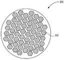
도 3에는 본 발명의 실시예에 따르는, 분리된 6각 타일 돌출부들을 그 위에 가지는 균일체를 가진 연마 패드의 평면도가 도시되어 있다.
도 4에는 본 발명의 실시예에 따르는, 원호형상 분리된 돌출부들을 그 위에 가진 연마 패드의 평면도가 도시되어 있다.
도 5에는 본 발명의 실시예에 따르는, 분리된 직선 부분 돌출부들을 그 위에 가지는 균일체를 가진 연마 패드의 평면도가 도시되어 있다.
도 6에는 본 발명의 실시예에 따르는, 국소 투명(local area transparency; LAT) 영역 및/또는 지시 영역을 포함하고 분리된 돌출부들을 그 위에 가지는 균일체를 가진 연마 패드의 평면도가 도시되어 있다.
도 7a 내지 도 7g에는 본 발명에 따르는, 분리된 돌출부들을 그 위에 가지는 균일체를 가진 연마 패드의 제조에 사용되는 공정의 단면도가 도시되어 있다.
도 8a 내지 도 8d에는 본 발명에 따르는, 분리된 돌출부들을 그 위에 가지는 균일체를 가진 다른 연마 패드의 제조에 사용되는 공정의 단면도가 도시되어 있다.
도 9에는 본 발명에 따르는, 분리된 돌출부들을 그 위에 가지는 균일체를 가진 연마 패드와 함께 사용가능한 연마 장치의 등측도가 도시되어 있다.1 is a cross-sectional view of a polishing pad having a homogeneous body having discrete protrusions thereon, according to an embodiment of the invention.
2 is a cross-sectional view of another polishing pad having a uniform body having separate protrusions thereon according to an embodiment of the present invention.
3 is a plan view of a polishing pad having a uniform body having separate hexagonal tile protrusions thereon according to an embodiment of the present invention.
4 is a plan view of a polishing pad having arcuate separated protrusions thereon, according to an embodiment of the invention.
5 is a plan view of a polishing pad having a uniform body having separate straight partial protrusions thereon according to an embodiment of the present invention.
FIG. 6 is a plan view of a polishing pad having a uniform body including local area transparency (LAT) regions and / or pointing regions and having separate protrusions thereon, according to an embodiment of the present invention.
7A-7G illustrate cross-sectional views of a process used for the manufacture of a polishing pad having a homogeneous body having separate protrusions thereon according to the present invention.
8a to 8d show cross-sectional views of a process used for the production of another polishing pad with a homogeneous body having separate protrusions thereon according to the invention.
9 shows an isometric view of a polishing apparatus usable with a polishing pad having a homogeneous body having separate protrusions thereon according to the present invention.
분리된 돌출부들을 그 위에 가지는 균일체를 가진 연마 패드는 본 명세서에 설명된다. 다음의 설명에서, 본 발명의 실시예에 관한 완전한 이해를 제공하기 위하여 특정 연마 패드 구성 및 설계와 같은 수개의 특정 세부사항이 설명된다. 본 발명의 실시예가 이들 특정 세부사항 없이도 실시될 수 있다는 것은 당해 기술분야의 통상의 기술자에게 자명할 것이다. 다른 예에서, 반도체 기판의 CMP를 실행하기 위한 연마 패드와 슬러리의 조합에 관한 세부사항과 같은 공지의 처리 기술은, 본 발명의 실시예를 불필요하게 불명료하게 하지 않기 위하여 상세하게 설명되지 않는다. 더욱이, 도면에 나타나 있는 여러 가지 실시예들이 예시하기 위한 것이고 반드시 일정한 비율로 도시된 것은 아니라는 점은 이해되어야 한다.Polishing pads having a uniform body having separate protrusions thereon are described herein. In the following description, several specific details are set forth such as specific polishing pad configurations and designs in order to provide a thorough understanding of embodiments of the present invention. It will be apparent to one skilled in the art that embodiments of the present invention may be practiced without these specific details. In other instances, well-known processing techniques, such as details relating to the combination of polishing pads and slurries for performing CMP of semiconductor substrates, have not been described in detail in order not to unnecessarily obscure embodiments of the present invention. Moreover, it is to be understood that the various embodiments shown in the figures are for illustration only and are not necessarily drawn to scale.
CMP 공정용 연마 패드는 횡방향-웨이퍼 연마 균일도 대 내부 금형 연마 균일도 사이와 같이 성능면에서 상충관계(trade-offs)를 가질 수 있다. 예를 들어, 경질 연마 패드는 양호한 금형 수준 평탄화를 나타내지만, 조악한 횡방향-웨이퍼 균일도를 나타낼 수 있다. 이에 반하여, 연질 연마 패드는 조악한 금형 수준 평탄화를 나타낼 수 있지만(예컨대, 이 연질 연마 패드는 금형 내부에 디싱(dishing)을 야기할 수 있음), 양호한 웨이퍼 수준 균일도를 나타낼 수 있다. 상술한 성능 상충관계를 경감시키는 것에 대한 접근법은 내부-웨이퍼 연마 효과와 내부-금형 연마 효과를 분리시키는 것일 수 있다.Polishing pads for CMP processes may have trade-offs in performance, such as between cross-wafer polishing uniformity versus internal mold polishing uniformity. For example, hard polishing pads exhibit good mold level flattening but may exhibit poor transverse-wafer uniformity. In contrast, soft polishing pads may exhibit poor mold level planarization (eg, these soft polishing pads may cause dishing inside the mold) but may exhibit good wafer level uniformity. An approach to alleviating the performance tradeoffs described above may be to separate the inner-wafer polishing effect from the inner-mold polishing effect.
일 실시예에서, 연질 서브패드는 경질 연마층과 쌍을 이루고 있다. 그러나, 타일 구조체와 같이 경질 연마층을 구성하는 구조체는 연마 공정 동안 연질 서브패드쪽으로 압축될 때 바람직하지 않게도 위로 구부려지기 쉽다. 더욱이, 연질 서브패드로부터 경질 연마층의 특징부들의 박리는 연마 패드의 수명을 상당히 감소시킬 수 있다.In one embodiment, the soft subpads are paired with a hard abrasive layer. However, the structures that make up the hard polishing layer, such as the tile structure, are undesirably susceptible to bending upward when pressed towards the soft subpad during the polishing process. Moreover, delamination of the features of the hard polishing layer from the soft subpad can significantly reduce the life of the polishing pad.
본 발명의 실시예에 따르면, 상술된 성능 상충관계를 경감시키는 것에 대한 접근법은 연질 균일체와 공유결합되는 분리된 경질 돌출부들을 가지는 연마 패드의 형성을 포함한다. 다른 연마 패드는 연질 균일체 상에 배치되는 분리된 경질 돌출부들을 가지는데, 이 돌출부는 압축 동안 분리된 돌출부들이 밑에 있는 균일체 속으로 쓰러지는 것을 억제하기 위해서 측면을 지지하지만 불연속인 경질의 부재들을 가진다. 밑에 있는 경질 균일체들 상에 배치되는 연질 연마 돌출부들과 같은 반대 배열 또한 여기에서 고려될 수 있다는 것은 이해되어야 한다.In accordance with an embodiment of the present invention, an approach to alleviating the performance trade-offs described above includes the formation of a polishing pad having separate hard protrusions covalently bonded with the soft homogeneous body. Another polishing pad has separate hard protrusions disposed on the soft homogeneous body, which have side-side but discontinuous hard members that support the side to prevent the separated protrusions from falling into the underlying homogenous during compression. . It should be understood that reverse arrangements, such as soft abrasive protrusions disposed on underlying hard uniforms, may also be considered here.
이러한 다층 연마 패드들은 돌출부들과 밑에 있는 균일체 사이의 화학 결합을 보장하기 위해서 몰딩 공정으로 제조될 수 있다. 예를 들어, 일 실시예에서, 다층 CMP 패드들은 제 2 패드 전구체를 부분적으로 경화처리된 제 1 패드 전구체 위에 형성하여 모든 부분들을 함께 추가로 경화시킴으로써 인시츄(in-situ) 제조된다. 제 1 재료는 미리 프레스성형되거나 프레스성형되지 않을 수 있다. 어느 경우에나, 전체 패드는 일체형 연마 패드로서 프레스성형되어 후 경화처리된다. 이러한 인시츄 접근법을 이용함으로써, 층들 사이의 화학 결합은 매우 강해서, 박리의 가능성을 감소시키거나 제거할 수 있다. 일 실시예에서, 미리 프레스하는 단계 또는 프레스하는 단계는 몰딩 장치의 상부와 하부를 함께 이동시키는 단계를 수반한다.Such multilayer polishing pads can be manufactured in a molding process to ensure chemical bonding between the protrusions and the underlying homogeneous. For example, in one embodiment, multilayer CMP pads are manufactured in-situ by forming a second pad precursor over a partially cured first pad precursor and further curing all the portions together. The first material may or may not be preformed in advance. In either case, the entire pad is press molded as a unitary polishing pad and post cured. By using this in situ approach, the chemical bonds between the layers are very strong, which can reduce or eliminate the possibility of delamination. In one embodiment, prepressing or pressing involves moving the top and bottom of the molding apparatus together.
본 발명의 일 양태에서, 연마 패드는 분리된 돌출부들을 그 위에 가지는 실질적으로 편평한 균일체가 제공된다. 예를 들어, 도 1에는 본 발명의 일 실시예에 따라, 분리된 돌출부들을 가지는 균일체를 가진 연마 패드의 단면도가 도시되어 있다. In one aspect of the invention, the polishing pad is provided with a substantially flat uniform body having separate protrusions thereon. For example, FIG. 1 is a cross-sectional view of a polishing pad having a uniform body with separate protrusions, in accordance with one embodiment of the present invention.
도 1을 참조하면, 연마 패드(100)는 기판을 연마하기 위하여 제공된다. 연마 패드(100)는 연마면(104)과 후면(106)을 가지는 균일체(102)를 포함한다. 균일체(102)는 제 1 경도를 가지는 재료로 이루어진다. 또한 연마 패드(100)는 균일체(102)의 연마면(104) 상에 배치되는 복수 개의 분리된 돌출부(108)들을 포함한다. 복수 개의 분리된 돌출부(108)들은 제 1 경도와 상이한 제 2 경도를 가지는 재료로 이루어진다. 일 실시예에서, 균일체(102)의 연마면(104)은 도 1에 도시된 바와 같이 실질적으로 편평하고, 복수 개의 분리된 돌출부(108)들 사이에 노출되어 있다. 이러한 일 실시예에서, 복수 개의 분리된 돌출부(108)들 각각은 균일체(102)의 연마면(104) 전체 평면에서 대략 5 내지 50mm 범위의 최단 치수를 가진다.Referring to FIG. 1, a
본 발명에 일 실시예에 따르면, 균일체(102)의 재료의 경도(제 1 경도)는 복수 개의 분리된 돌출부(108)들의 재료의 경도(제 2 경도)보다 작다. 이러한 일 실시예에서, 제 1 경도는 대략 쇼어 경도 D 스케일로 40보다 작고, 제 2 경도는 대략 쇼어 경도 D 스케일로 30보다 크다. 이러한 특정 실시예에서, 제 1 경도는 대략 쇼어 경도 D 스케일로 25보다 작고, 제 2 경도는 대략 쇼어 경도 D 스케일로 40보다 크다.According to one embodiment of the invention, the hardness (first hardness) of the material of the
본 발명의 다른 실시예에 따르면, 균일체(102)의 재료의 경도(제 1 경도)는 복수 개의 분리된 돌출부(108)들의 재료의 경도(제 2 경도)보다 크다. 이러한 일 실시예에서, 제 2 경도는 대략 쇼어 경도 D 스케일로 40보다 작고, 제 1 경도는 대략 쇼어 경도 D 스케일로 30보다 크다. 이러한 특정 실시예에서, 제 2 경도는 대략 쇼어 경도 D 스케일로 25보다 작고, 제 1 경도는 대략 쇼어 경도 D 스케일로 40보다 크다.According to another embodiment of the present invention, the hardness (first hardness) of the material of the
본 발명의 다른 양태에서, 연마 패드에는 표면형상적으로 패턴이 형성된 균일체가 제공되고, 이 균일체는 분리된 돌출부들을 그 위에 가진다. 예를 들어, 도 2에는 본 발명의 일 실시예에 따라, 분리된 돌출부들을 그 위에 가지는 균일체를 가진 다른 연마 패드의 단면도가 도시되어 있다.In another aspect of the invention, the polishing pad is provided with a surface-shaped patterned uniform, which has separate projections thereon. For example, FIG. 2 shows a cross-sectional view of another polishing pad with a uniform body having separate protrusions thereon, according to one embodiment of the invention.
도 2를 참조하면, 연마 패드(200)는 기판을 연마하기 위하여 제공된다. 연마 패드(200)는 연마면(204)과 후면(206)을 가지는 균일체(202)를 포함한다. 균일체(202)는 제 1 경도를 가지는 재료로 이루어진다. 균일체(202)의 연마면(204)은 패턴을 가지는 복수 개의 돌출부(207)들을 포함한다. 또한 연마 패드(200)는 균일체(202)의 연마면(204)의 복수 개의 돌출부(207)들 상에 배치되고, 이 돌출부들과 정렬되는 복수 개의 분리된 돌출부(208)들을 포함한다. 복수 개의 분리된 돌출부(208)들은 복수 개의 돌출부(207)들의 패턴을 가지고, 제 1 경도와 상이한 제 2 경도를 가지는 재료로 이루어진다. 또한 연마 패드(200)는 균일체(202) 상에 배치되는 충전층(210)을 균일체(202)의 연마면(204)의 복수 개의 돌출부(207)들 둘레에서 포함한다. 충전층은 복수 개의 분리된 돌출부(208)들의 재료로 이루어진다. 이러한 일 실시예에서, 복수 개의 돌출부(207)들 각각 및 복수 개의 분리된 돌출부(208)들 각각은 균일체(202)의 연마면(204)의 전체 평면에서 대략 5 내지 50mm 범위의 최단 치수를 가진다.Referring to FIG. 2, a
일 실시예에서, 충전층(210)은 복수 개의 분리된 돌출부(208)들과 불연속적이다. 즉, 도 2를 참조하면, 충전층은 위치(212)에서 복수 개의 분리된 돌출부(208)들에 결합되지 않거나 이 돌출부들과 연속적이지 않는다. 이러한 배열은 연마 공정 동안 복수 개의 분리된 돌출부(208)들 각각을 균일체(202) 쪽으로 자유롭게 압축시킬 수 있다. 그러나, 불연속적인 충전층(210)의 존재는 복수 개의 분리된 돌출부(208)들 각각이 균일체(202) 쪽으로 압축됨에 따라 돌출부(208)들 각각의 양쪽면을 안내하고 지지할 수 있다. 그러나, 다른 실시예에서, 충전층(210)은 복수 개의 분리된 돌출부(208)들과 연속적이다.In one embodiment, the
본 발명의 일 실시예에 따르면, 균일체(202)의 재료의 경도(제 1 경도)는 충전층(210)과 복수 개의 분리된 돌출부(208)들의 재료의 경도(제 2 경도)보다 작다. 이러한 일 실시예에서, 제 1 경도는 대략 쇼어 경도 D 스케일로 40보다 작고, 제 2 경도는 대략 쇼어 경도 D 스케일로 30보다 크다. 이러한 특정 실시예에서, 제 1 경도는 대략 쇼어 경도 D 스케일로 25보다 작고, 제 2 경도는 대략 쇼어 경도 D 스케일로 40보다 크다.According to one embodiment of the invention, the hardness (first hardness) of the material of the
본 발명의 다른 실시예에 따르면, 균일체(202)의 재료의 경도(제 1 경도)는 충전층(210)과 복수 개의 분리된 돌출부(208)들의 재료의 경도(제 2 경도)보다 크다. 이러한 일 실시예에서, 제 2 경도는 쇼어 경도 D 스케일로 40보다 작고, 제 1 경도는 대략 쇼어 경도 D 스케일로 30보다 크다. 이러한 특정 실시예에서, 제 2 경도는 대략 쇼어 경도 D 스케일로 25보다 작고, 제 1 경도는 대략 쇼어 경도 D 스케일로 40보다 크다.According to another embodiment of the present invention, the hardness (first hardness) of the material of the
연마 패드들(100, 200) 내부의 상이한 재료의 부분들은 서로 공유 결합될 수 있다. 예를 들어, 도 1을 참조하면, 일 실시예에서, 복수 개의 분리된 돌출부(108)들은 균일체(102)의 연마면(104) 위에 배치되고 이 연마면과 공유 결합된다. 다른 예에서, 도 2를 참조하면, 일 실시예에서, 복수 개의 분리된 돌출부(208)들과 충전층(210) 모두는 균일체(202)와 공유 결합된다. 구체적으로, 충전층(210)은 연마면(204)의 패턴 내부에서 공유 결합되는 반면, 복수 개의 분리된 돌출부(208)들은 연마면(204)의 패턴의 정상에서 공유 결합된다.Portions of different material within the polishing
일 실시예에서, "공유 결합(covalently bonded)"이라는 용어는 제 1 재료(예컨대, 균일체(102 또는 202)의 재료)의 원자들이 제 2 재료(예컨대, 복수 개의 분리된 돌출부들(108 또는 208)의 재료)원자들과 전자를 공유하거나 가교결합되어, 실제 화학 결합을 유발한다. 이러한 공유 결합은 정전기적 상호작용과 구별되는데, 이 정전기적 상호작용은 연마 패드의 일부가 절단되어 상이한 재료의 삽입 구역으로 교체된다면 발생할 수 있다. 또한 공유 결합은 나사, 못, 아교 또는 다른 접착제를 통한 결합과 같은 기계적 결합과 구별된다. 아래에서 상술되는 바와 같이, 공유 결합은 복수 개의 분리된 돌출부들을 가진 연마체를 적어도 어느 정도 함께 경화시킴으로써 달성될 수 있고, 이는 복수 개의 분리된 돌출부들과 연마체의 완전한 개별적인 성형과는 정반대이다.In one embodiment, the term "covalently bonded" means that the atoms of the first material (eg, the material of the homogenous 102 or 202) are separated from the second material (eg, the plurality of
연마 패드(100 또는 200)의 재료들은 몰드성형될 수 있다. 예를 들어, 도 1을 참조하면, 일 실시예에서, 균일체(102)는 몰드성형된 균일체이고, 복수 개의 분리된 돌출부(108)들은 복수 개의 몰드성형된 돌출부들이다. 다른 예에서, 도 2를 참조하면, 일 실시예에서, 균일체(202)는 몰드성형된 균일체이고, 복수 개의 분리된 돌출부(208)들은 복수 개의 몰드성형된 돌출부들이고, 충전층(210)은 몰드성형된 충전층이다.The materials of polishing
"몰드성형된(molded)"이라는 용어는 균일체 및/또는 균일체 상의 분리된 돌출부들이 도 7a 내지 도 7g 및 도 8a 내지 도 8d와 함께 이하에서 더 상세하게 설명되는 바와 같이 성형 몰드 내에 형성된다는 것을 지시하는데 사용될 수 있다. 일 실시예에서, 몰드성형된 분리된 돌출부들은 컨디셔닝(conditioning) 및/또는 연마 시 대략 1 내지 5 미크론 제곱 평균 제곱근(root mean square)의 범위 의 연마 표면 거칠기를 가진다. 일 실시예에서, 몰드성형된 분리된 돌출부들은 컨디셔닝 및/또는 연마 시 대략 2.35 미크론 제곱 평균 제곱근의 연마 표면 거칠기를 가진다. 일 실시예에서, 몰드성형된 분리된 돌출부들은 25℃에서 대략 30 내지 500 메가파스칼(MPa) 범위의 저장 탄성율(storage modulus)을 가진다. 다른 실시예에서, 몰드성형된 분리된 돌출부들은 25℃에서 대략 30 메가파스칼(MPa)보다 작은 범위의 저장 탄성율을 가진다. 일 실시예에서, 도 7a 내지 도 7g 및 도 8a 내지 도 8d와 함께 설명되는 바와 같이, 연마 패드는 몰드성형된 연마체와 연마체 상의 몰드성형된 분리된 돌출부들로 이루어진다.The term “molded” means that the homogeneous and / or discrete protrusions on the homogeneous are formed in a molding mold as described in more detail below in conjunction with FIGS. 7A-7G and 8A-8D. Can be used to indicate. In one embodiment, the molded discrete protrusions have a polishing surface roughness in the range of approximately 1 to 5 micron root mean square upon conditioning and / or polishing. In one embodiment, the molded discrete protrusions have an abrasive surface roughness of approximately 2.35 microns squared mean square root when conditioning and / or polishing. In one embodiment, the molded discrete protrusions have a storage modulus in the range of approximately 30 to 500 megapascals (MPa) at 25 ° C. In another embodiment, the molded discrete protrusions have a storage modulus in the range of less than approximately 30 megapascals (MPa) at 25 ° C. In one embodiment, as described in conjunction with FIGS. 7A-7G and 8A-8D, the polishing pad consists of a molded abrasive body and molded discrete protrusions on the abrasive body.
연마 패드들(100 또는 200)은 열경화성 폴리우레탄 재료로 이루어진 균일체를 포함할 수 있다. 일 실시예에서, 균일체는 열경화성인 폐포(closed cell) 폴리우레탄 재료로 이루어진다. 일 실시예에서, "균일(homogeneous)"이라는 용어는 열경화성인 폐포 폴리우레탄 재료의 조성이 균일체의 전체 조성에 걸쳐 일정하다는 것을 지시하는데 사용된다. 예를 들어, 일 실시예에서, "균일한"이라는 용어는, 예컨대 함침성 펠트 또는 상이한 재료의 다층 조성물(복합재료)로 이루어진 연마체와 연마 패드를 제외한다.The polishing
일 실시예에서, "열경화성(thermoset)"이라는 용어는 비가역적으로 경화하는 폴리머 재료를 지시하는데 사용되는데, 예를 들어, 이 폴리머 재료에 대한 전구체는 경화에 의해 비가역적으로 변하여 비용융성, 불용성 폴리머 망상조직(network)이 된다. 예를 들어, 일 실시예에서, "열경화성"이라는 용어는, 가열될 때 액체로 바뀌고 충분히 냉각될 때 바로 유리질 상태로 바뀌는 폴리머로 이루어진 재료들, 예컨대 "열가소성(thermoplast)" 재료들, 즉 "열가소성물질(thermoplastics)"로 이루어진 연마 패드들은 제외한다. 열경화성 재료들로 만들어진 연마 패드들은, 화학 반응에서 폴리머를 형성하기 위해 반응하는 저 분자량 전구체들로부터 통상 제조되는 반면, 열가소성 재료들로 만들어진 패드들은, 연마 패드가 물리적 공정에서 형성되도록 상 변화를 일으키기 위해서 미리 존재하는 폴리머를 가열함으로써 통상 제조된다는 점을 유의해야 한다. 폴리우레탄 열경화성 폴리머는 여기에서 설명되는 연마 패드를 제조하기 위하여 안정된 열적 기계적 특성, 화학적 환경에 대한 저항성 및 내마모성 특성에 기초하여 선택될 수 있다.In one embodiment, the term “thermoset” is used to indicate a polymer material that cures irreversibly, for example, the precursor to this polymer material is irreversibly changed by curing, thereby making it insoluble, insoluble polymer. It becomes a network. For example, in one embodiment, the term "thermoset" refers to materials consisting of polymers, such as "thermoplast" materials, ie "thermoplastics," which change into a liquid when heated and immediately into a glassy state when cooled sufficiently. Polishing pads made of " thermoplastics " Polishing pads made of thermoset materials are usually made from low molecular weight precursors that react to form polymers in chemical reactions, while pads made of thermoplastic materials are used to cause phase changes such that the polishing pad is formed in a physical process. It should be noted that it is usually prepared by heating a polymer that already exists. Polyurethane thermoset polymers may be selected based on stable thermal mechanical properties, resistance to chemical environments and wear resistance properties to produce the polishing pads described herein.
일 실시예에서, 도 1을 참조하면, 균일체(102)의 재료는 제 1 열경화성 폴리우레탄 재료로 이루어지고, 복수 개의 분리된 돌출부(108)들의 재료는 상이한 제 2 열경화성 폴리우레탄 재료로 이루어진다. 일 실시예에서, 도 2를 참조하면, 균일체(202)의 재료는 제 1 열경화성 폴리우레탄 재료로 이루어지고, 복수 개의 돌출부(208)들과 충전층(210)의 재료는 상이한 제 2 열경화성 폴리우레탄 재료로 이루어진다.In one embodiment, referring to FIG. 1, the material of the homogenous 102 is made of a first thermoset polyurethane material, and the material of the plurality of
일 실시예에서, 연마 패드들(100 또는 200)과 같이 여기에서 설명되는 연마 패드들은 연마체 및/또는 연마체 상의 분리된 돌출부들을 포함하고, 이 분리된 돌출부들은 그 내부에 복수 개의 폐포 기공들을 가진다. 일 실시예에서, 복수 개의 폐포 기공들은 복수 개의 포로겐이다. 예를 들어, "포로겐(porogen)"이라는 용어는 "중공형(hollow)" 중앙부들을 가진 마이크로 또는 나노 크기의 구형 입자 또는 어느 정도 구형 입자를 지시하는데 사용될 수 있다. 중공형 중앙부들은 고체 재료로 채워지는 것이 아니라, 기체 코어 또는 액체 코어를 포함할 수 있다. 일 실시예에서, 복수 개의 폐포 기공들은 미리 확장되어 가스가 충전된 EXPANCELTM로 이루어지는데, 이 EXPANCELTM은 연마체 및/또는 연마 패드의 분리된 돌출부들 전체에 걸쳐(예컨대, 그 안의 추가 구성요소로서) 분포된다. 특정 실시예에서, EXPANCELTM은 펜테인으로 충전되어 있다. 일 실시예에서, 복수 개의 폐포 기공들 각각은 대략 10 내지 100 미크론 범위의 직경을 가진다. 일 실시예에서, 복수 개의 폐포 기공들은 서로 분리되어 있는 기공들을 포함한다. 이는 개포(open cell) 기공들과 대조되는데, 개포 기공은 일반 스펀지 내의 기공들에서와 같이 터널을 통하여 서로 연결될 수 있다. 일 실시예에서, 폐포 기공들 각각은 상술된 바와 같이 포로겐의 셸(a shell of porogen)과 같은 물리적인 셸(physical shell)을 포함한다. 그러나, 다른 실시예에서, 폐포 기공들 각각은 물리적인 셸을 포함하지 않는다. 일 실시예에서, 복수 개의 폐포 기공들은 균일체의 열경화성 폴리우레탄 재료 또는 균일체 상에 배치되는 균일한 복수 개의 분리된 돌출부들의 열경화성 폴리우레탄 재료 전체에 걸쳐 본질적으로 고르게 분포된다.In one embodiment, the polishing pads described herein, such as the
일 실시예에서, 복수 개의 폐포들의 농도 내지 밀도는 균일체(예컨대 102 또는 202)와 복수 개의 분리된 돌출부들(예컨대, 108 또는 208) 사이에서 상이하다. 이러한 일 실시예에서, 균일체 내의 폐포들의 농도 내지 밀도는 복수 개의 분리된 돌출부들 내의 폐포들의 농도 내지 밀도보다 작다. 이러한 특정 실시예에서, 균일체 내에는 폐포들이 없는 반면, 복수 개의 분리된 돌출부들 내에는 폐포들이 있다. 대체 실시예에서, 균일체 내의 폐포들의 농도 내지 밀도는 복수 개의 분리된 돌출부들 내의 폐포들의 농도 내지 밀도보다 크다. 다른 실시예에서, 폐포들의 유형은 균일체와 복수 개의 분리된 돌출부들 사이에서 상이하다.In one embodiment, the concentration to density of the plurality of alveoli is different between the homogeneous (eg 102 or 202) and the plurality of discrete protrusions (eg 108 or 208). In one such embodiment, the concentration or density of alveoli in the uniform is less than the concentration or density of alveoli in the plurality of discrete protrusions. In this particular embodiment, there are no alveoli in the uniform, while there are alveoli in the plurality of discrete protrusions. In an alternate embodiment, the concentration to density of the alveoli in the uniform is greater than the concentration to density of the alveoli in the plurality of discrete protrusions. In another embodiment, the type of alveoli is different between the homogeneous body and the plurality of discrete protrusions.
일 실시예에서, 연마 패드들(100 또는 200)과 같이 여기에 설명되는 연마 패드들은 불투명한 분리된 돌출부들 및/또는 연마체를 포함한다. 일 실시예에서, "불투명(opaque)"이라는 용어는 대략 10% 이하의 가시광선이 통과하는 것을 허용하는 재료를 지시하는데 사용된다. 일 실시예에서, 연마체 및/또는 분리된 돌출부들은 대부분 불투명한데, 이는 전적으로 감마제(lubricant)와 같은 불투명 입자 충전재가 분리된 돌출부들 및/또는 연마체 전체에 걸쳐서(예컨대, 그 내부의 추가 구성요소들로서) 포함되어 있기 때문이다. 특정 실시예에서, 불투명 입자 충전재는 질화붕소, 불화 세륨, 흑연, 불화 흑연, 황화 몰리브덴, 황화 니오븀, 활석, 황화 탄탈룸, 이황화 텅스텐 또는 테플론(Teflon®)과 같은 재료이지만, 이에 제한되지 않는다.In one embodiment, the polishing pads described herein, such as polishing
일 실시예에서, 입자 충전재의 농도 내지 불투명도는 균일체(예컨대 102 또는 202)와 복수 개의 분리된 돌출부들(예컨대, 108 또는 208) 사이에서 상이하다. 이러한 일 실시예에서, 균일체 내의 입자 충전재의 농도는 복수 개의 분리된 돌출부 내의 입자 충전재의 농도보다 작다. 이러한 특정 실시예에서, 균일체 내에는 입자 충전재가 포함되지 않는 반면, 복수 개의 분리된 돌출부들 내에는 입자 충전재가 포함된다. 대체 실시예에서, 균일체 내의 입자 충전재의 농도는 복수 개의 분리된 돌출부들 내의 입자 충전재의 농도보다 크다. 다른 실시예에서, 입자 충전재의 유형은 균일체와 복수 개의 분리된 돌출부들 사이에서 상이하다.In one embodiment, the concentration to opacity of the particle filler is different between the homogeneous body (eg 102 or 202) and the plurality of separate protrusions (eg 108 or 208). In one such embodiment, the concentration of particle filler in the homogeneous is less than the concentration of particle filler in the plurality of discrete protrusions. In this particular embodiment, the particle filler is not included in the homogeneous body, while the particle filler is included in the plurality of separate protrusions. In an alternate embodiment, the concentration of particle filler in the homogeneous is greater than the concentration of particle filler in the plurality of discrete protrusions. In another embodiment, the type of particle filler is different between the homogeneous body and the plurality of separate protrusions.
본 발명의 일 양태에서, 복수 개의 분리된 돌출부들(108 또는 208)은 CMP 공정 동안 연마에 적합한 패턴을 가질 수 있다. 일반적인 제 1 예에서, 본 발명의 일부 실시예들은 타일 패턴을 가지는 복수 개의 분리된 돌출부들을 포함한다. 이러한 특정 실시예에서, 도 3에는 본 발명의 일 실시예에 따르는, 분리된 육각 타일 돌출부(302)들을 그 위에 가지는 균일체를 가진 연마 패드(300)의 평면도가 도시되어 있다. 이러한 다른 특정 실시예는 복수 개의 원형 타일, 타원형 타일, 정사각형 타일, 직사각형 타일 또는 그 조합을 포함하지만, 이에 제한되지 않는다.In one aspect of the invention, the plurality of
일반적인 제 2 예에서, 본 발명의 일부 실시예들은 곡선 모양의 패턴을 가지는 복수 개의 분리된 돌출부들을 포함한다. 이러한 특정 예에서, 도 4에는 본 발명의 일 실시예에 따르는, 균일체 상에 원호형상 분리된 돌출부(402)들을 가지는 균일체를 가진 연마 패드(400)의 평면도가 도시되어 있다. 이러한 다른 특정 실시예는 연마 패드의 실질적인 원형 균일체 상에 배치되는, 부분적으로 원주상에 배치된 복수 개의 돌출부들을 포함하지만, 이에 제한되지 않는다.In a second general example, some embodiments of the present invention include a plurality of separate protrusions having a curved pattern. In this particular example, FIG. 4 shows a top view of a
일반적인 제 3 예에서, 본 발명의 일부 실시예들은 직선 모양의 패턴을 가지는 복수 개의 분리된 돌출부들을 포함한다. 이러한 특정 예에서, 도 5에는 본 발명에 따르는 분리된 직선 부분 돌출부(502)들을 그 위에 가지는 균일체를 가진 연마 패드(500)의 평면도가 도시되어 있다. 나타나 있는 분리된 직선 부분 돌출부들은 연마 표면의 반경에 대해 본질적으로 직각이다. 그러나, 본 발명의 실시예 또한 연마 표면의 반경에 대해 정확히 직각이 아닌 분리된 직선 부분들을 포함할 수 있다는 것은 이해되어야 한다. 이러한 실시예에서, 분리된 직선 부분들은 동심 또는 대략 동심인 다각형 배열의 일부를 형성할 수 있지만, 그 전부를 형성하지는 않는다. 대응하는 반경과의 상대적인 결합은 정확히 90도는 아니고, 아마도 90도에서 약간 모자란 각도이다. 그럼에도 불구하고 이러한 거의 직각 또는 대략 직각인 분리된 직선 부분들은 본 발명의 범위와 사상 내에 있는 것으로 여겨진다.In a third general example, some embodiments of the invention include a plurality of separate protrusions having a straight pattern. In this particular example, FIG. 5 shows a top view of a
일 실시예에서, 연마 패드들(100, 200, 300, 400 또는 500)과 같이 여기에 설명되는 연마 패드들은 기판들을 연마하는데 적합하다. 기판은 디바이스 또는 디바이스 상에 배치되는 다른 층들을 가지는 실리콘 기판과 같이 반도체 제조 산업에서 사용되는 한가지일 수 있다. 그러나, 기판은 MEMS 장치, 레티클 또는 태양광 모듈용 기판과 같은 것일 수 있지만, 이에 제한되지 않는다. 따라서, 여기에서 사용되는 바와 같이 "기판을 연마하기 위한 연마 패드"로 지칭하는 것은 이들 및 관련 가능성을 포함하도록 의도되어 있다.In one embodiment, the polishing pads described herein, such as polishing
균일체와 균일체 상에 배치되는 분리된 돌출부들의 치수결정은 적용처에 따라 변경될 수 있다. 그럼에도 불구하고, 특정 파라미터들은 연마 패드, 즉 이러한 균일체를 포함하고, 균일체 상에 배치되면서 종래의 처리 장치 또는 나아가 종래의 화학적 기계적 처리 공정과 함께 사용가능한 분리된 돌출부들을 가진 연마 패드들을 만드는데 사용될 수 있다. 예를 들어, 본 발명의 일 실시예에 따르면, 균일체와 균일체 상에 배치되는 분리된 돌출부들의 조합은 대략 0.075 인치 내지 0.130 인치 범위, 예컨대 대략 1.9 내지 3.3mm 범위의 두께를 가진다. 일 실시예에서, 균일체는 대략 20 인치 내지 30.3 인치의 범위, 예컨대 50 내지 77cm의 범위, 가능하게는 대략 10 인치 내지 42 인치, 예컨대 25 내지 107cm의 범위의 직경을 가진다. 일 실시예에서, 균일체 및/또는 균일체 상에 배치되는 분리된 돌출부들은 대략 6% 내지 36% 총 공극 체적 범위, 가능하게는 대략 15% 내지 35% 총 공극 체적 범위의 기공 밀도(pore density)를 가진다. 일 실시예에서, 균일체와 균일체 상에 배치되는 분리된 돌출부들의 조합은 대략 2.5%의 압축률을 가진다. 일 실시예에서, 균일체는 대략 0.70 내지 1.05 g/cm3의 범위의 밀도를 가진다.The dimensioning of the uniform body and of the separate protrusions disposed on the uniform body may vary depending on the application. Nevertheless, certain parameters may be used to make a polishing pad, i.e., a polishing pad comprising such a homogeneous body and having separate protrusions disposed on the homogenous body and usable with a conventional processing apparatus or even a conventional chemical mechanical treatment process. Can be. For example, according to one embodiment of the present invention, the combination of the homogeneous body and the separate protrusions disposed on the homogeneous body has a thickness in the range of approximately 0.075 inches to 0.130 inches, such as approximately 1.9 to 3.3 mm. In one embodiment, the uniform has a diameter in the range of approximately 20 inches to 30.3 inches, such as in the range of 50 to 77 cm, possibly in the range of approximately 10 inches to 42 inches, such as 25 to 107 cm. In one embodiment, the homogeneous and / or discrete protrusions disposed on the homogeneous have a pore density in the range of approximately 6% to 36% total pore volume, possibly in the range of approximately 15% to 35% total pore volume. ) In one embodiment, the combination of the homogeneous body and the separated protrusions disposed on the homogeneous body has a compressibility of approximately 2.5%. In one embodiment, the uniform has a density in the range of approximately 0.70 to 1.05 g / cm3 .
본 발명의 다른 양태에서, 분리된 돌출부들을 그 위에 가지는 균일체를 가진 연마 패드는, 예컨대 와전류 탐지 시스템에 이용하기 위한 탐지 영역을 더 포함한다. 예를 들어, 도 6에는 본 발명에 따르는 국소 투명(LAT) 영역 및/또는 지시 영역을 포함하고 분리된 돌출부들을 그 위에 가지는 균일체를 가진 연마 패드(600)의 평면도가 도시되어 있다.In another aspect of the invention, the polishing pad having a uniform body having separate protrusions thereon further comprises a detection area, for example for use in an eddy current detection system. For example, FIG. 6 shows a plan view of a
도 6을 참조하면, 연마 패드(600)의 연마 표면(602)은 연마 패드(600)의 후면에 배치되는 탐지 영역의 위치를 지시하는 지시 영역(604)를 포함한다. 일 실시예에서, 지시 영역(604)은 도 6에 도시된 바와 같이 돌출부(608)들의 제 2 패턴으로 돌출부(606)들의 패턴을 차단한다. 와전류 탐지 영역과 같은 적합한 탐지 영역의 예시들은, 2010년 9월 30일에 출원되고 넥스플래너 코퍼레이션(NexPlanar Corporation)에 양도된 미국 특허 출원 제12/895,465호에 설명되어 있다.Referring to FIG. 6, the polishing
다른 양태에서, 분리된 돌출부들을 그 위에 가지는 균일체를 가진 연마 패드는 연마 패드 내에 배치되는 국소 투명(LAT) 영역을 더 포함한다. 예를 들어, 도 6을 참조하면, LAT 영역(610)은 연마 패드(600)의 연마체 내에 배치된다. 도 6에 도시된 바와 같이, LAT 영역(604)은 돌출부(606)들의 패턴을 차단한다. 일 실시예에서, LAT 영역(610)은 연마 패드(600)의 균일체 내에 배치되고, 이 균일체와 공유 결합된다. 적합한 LAT 영역들의 예시들은 2010년 9월 30일에 출원되어 넥스플래너 코퍼레이션에 양도된 미국 특허 출원 제12/895,465에 설명되어 있다.In another aspect, the polishing pad having a uniform body having separate protrusions thereon further comprises a local transparent (LAT) region disposed within the polishing pad. For example, referring to FIG. 6, the
본 발명의 다른 양태에서, 균일체 상에 배치되는 복수 개의 분리된 돌출부들을 가진 균일체를 가지는 연마 패드들은 몰딩 공정으로 제조될 수 있다. 이러한 제 1 예에서, 도 7a 내지 도 7g에는 본 발명의 일 실시예에 따르는, 분리된 돌출부들을 그 위에 가지는 균일체를 가진 연마 패드의 제조에 이용되는 공정의 단면도가 도시되어 있다.In another aspect of the invention, polishing pads having a uniform body having a plurality of separate protrusions disposed on the uniform body may be manufactured by a molding process. In this first example, FIGS. 7A-7G illustrate cross-sectional views of a process used in the manufacture of a polishing pad having a uniform body having separate protrusions thereon, according to one embodiment of the present invention.
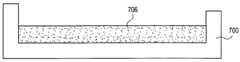
도 7a를 참조하면, 성형 몰드(700)가 제공된다. 도 7b를 참조하면, 프리-폴리머(702)와 경화제(704)는 도 7c에 도시된 바와 같이 성형 몰드 내에서 제 1 혼합물(706)을 형성하기 위해서 혼합된다. 일 실시예에서, 프리-폴리머(702)와 경화제(704)를 혼합하는 단계는 이소시안산염과 방향족 디아민 화합물을 각각 혼합하는 단계를 포함한다. 일 실시예에서, 혼합하는 단계는 연마 패드의 불투명 몰드성형된 균일체를 최종적으로 제공하기 위해서 불투명 입자 충전재를 프리-폴리머(702)와 경화제(704)에 첨가하는 단계를 더 포함한다. 특정 실시예에서, 불투명 입자 충전재는 질화붕소, 불화 세륨, 흑연, 불화 흑연, 황화 몰리브덴, 황화 니오븀, 활석, 황화 탄탈룸, 이황화 텅스텐 또는 테플론(Teflon®)과 같은 재료이지만, 이에 제한되지 않는다.Referring to FIG. 7A, a
일 실시예에서, 제 1 혼합물(706)은 열경화성 폐포 폴리우레탄 재료로 이루어진 몰드성형된 균일체를 최종적으로 형성하는데 사용된다. 일 실시예에서, 제 1 혼합물(706)은 경질 균일체를 최종적으로 형성하는데 사용되고, 단일 유형의 경화제만이 사용된다. 다른 실시예에서, 제 1 혼합물(706)은 연질 균일체를 최종적으로 형성하는데 사용되고, 제 1 경화제와 제 2 경화제의 조합이 사용된다. 예를 들어, 특정 실시예에서, 프리-폴리머는 폴리우레탄 전구체를 포함하고, 제 1 경화제는 방향족 디아민 화합물을 포함하며, 제 2 경화제는 에테르 결합을 가지는 화합물을 포함한다. 특정 실시예에서, 폴리우레탄 전구체는 이소시안산염이고, 제 1 경화제는 방향족 디아민이며, 제 2 경화제는 폴리테트라메틸렌 글리콜, 아미노 기능화 글리콜 또는 아미노 기능화 폴리옥시프로필렌과 같은 경화제이지만 이에 제한되지 않는다. 일 실시예에서, 프리-폴리머, 제 1 경화제 및 제 2 경화제는 대략 100 몰부(parts) 프리-폴리머, 85 몰부(parts) 제 1 경화제 및 15 몰부(parts) 제 2 경화제의 몰비를 가진다. 프리-폴리머와 제 1 경화제 및 제 2 경화제의 특정 성질에 기초해서 또는 다양한 경도 값을 가진 균일체를 제공하기 위해, 다양한 몰비가 사용될 수 있다는 것은 이해되어야 한다.In one embodiment, the
도 7d를 참조하면, 혼합물(706)은 연마면(710)과 후면(712)을 가지는 몰드성형된 균일체를 형성하기 위해서 적어도 부분적으로 경화된다. 부분적으로 경화시키는 단계는 성형 몰드 덮개가 존재하거나 부존재하는 상태에서 몰드(700)를 가열함으로써 실행될 수 있다. 그리고 나서 제 2 프리-폴리머와 제 2 경화제는 도 7e에 도시된 바와 같이 몰드성형된 균일체(708) 상에 제 2 혼합물(714)을 형성하기 위해서 혼합된다. 일 실시예에서, 제 2 혼합물(714)은 경질 재료를 형성하기 위한 것이고 단일 경화제와 함께 프리-폴리머가 사용되는 반면(2 탱크 공정), 제 1 혼합물(706)은 연질 재료를 형성하기 위한 것이고 제 1 경화제 및 제 2 경화제와 함께 프리-폴리머가 사용된다(3 탱크 공정). 대체 실시예에서, 제 1 혼합물(706)은 경질 재료를 형성하기 위한 것이고 단일 경화제와 함께 프리-폴리머가 사용되는 반면(2 탱크 공정), 제 2 혼합물(714)은 연질 재료를 형성하기 위한 것이고 제 1 경화제 및 제 2 경화제와 함께 프리-폴리머가 사용된다(3 탱크 공정). 따라서, 일 실시예에서, 제 2 혼합물(714)은 제 1 혼합물(706)과 상이하다. 그러나, 대체 실시예에서, 2개의 혼합물들은 동일하다. 또한, 일 실시예에서, 제 2 혼합물은 부분적으로 또는 완전히 경화된 제 1 혼합물(706) 상에 분배된다. 그러나, 대체 실시예에서, 제 2 혼합물(714)을 분배하는 단계 또는 주입하는 단계는, 동일 층이지만 상이한 영역에 적용되도록, 제 1 혼합물(706) 속에 인시츄 주입될 수 있다. 이러한 특정 실시예에서, 중앙 링과 외부 링은 상이한 제제(formulation)들을 가진다. 2개의 개별적인 층들이 형성되는 일 실시예에서, 층들 사이의 화학 결합을 강화하기 위하여, 상이한 층들 내부의 작용기의 비율은 상이하고, 예컨대 한 층은 -NCO가 많고 다른 층은 -NH2 및/또는 -OH가 많다. 일 실시예에서, 코팅은 상이한 층들 사이에 가해진다. 일 실시예에서, 침투가 층들 사이에서 발생하고, 공유 결합과 같은 화학 결합을 강화한다.Referring to FIG. 7D, the
일 실시예에서, 제 2 프리-폴리머와 제 2 경화제를 혼합하는 단계는 불투명한 복수 개의 분리된 돌출부(718)들을 형성하기 위해서 불투명 입자 충전재를 제 2 프리-폴리머와 제 2 경화제에 첨가하는 단계를 더 포함한다. 일 실시예에서, 제 1 혼합물(706)을 형성하기 위해서 제 1 프리-폴리머와 제 1 경화제를 혼합하는 단계는 제 1 혼합물(706)에서 가스를 제거하는 단계를 포함하고, 제 2 혼합물(714)을 형성하기 위해서 제 2 프리-폴리머와 제 2 경화제를 혼합하는 단계는 제 2 혼합물(714)에서 가스를 제거하는 단계를 포함한다.In one embodiment, the mixing of the second pre-polymer and the second curing agent comprises adding an opaque particulate filler to the second pre-polymer and the second curing agent to form a plurality of opaque
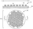
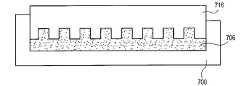
도 7f를 참조하면, 성형 몰드(700)의 덮개(716)는 제 2 혼합물(714) 속에 위치된다. 덮개(716)의 평면도는 위에 나타나 있는 반면, a-a'축의 단면도는 도 7f의 아래에 나타나 있다. 덮개(716)는, 도 7f에 도시된 바와 같이 도 3과 함께 설명된 돌출부들의 패턴에 대응하는 그루브들의 패턴과 같이, 덮개 위에 배치된 그루브들의 패턴을 가진다. 그러나, 대신하여, 덮개(716)는 도 4와 도 5와 함께 설명된 돌출부들의 그루브들에 대응하는 그루브들의 패턴을 가진다.Referring to FIG. 7F, the
여기에 설명되는 실시예가 성형 몰드(700)의 덮개(716)를 하강시키는 것을 설명하고, 성형 몰드(700)의 기저부와 덮개(716)를 함께 작동시키는 달성만을 필요로 한다는 것은 이해되어야 한다. 즉, 일부 실시예에서는 성형 몰드(700)의 기저부가 성형 몰드의 덮개(716)를 향하여 들어올려지는 반면, 다른 실시예에서는 성형 몰드(700)의 기저부가 성형 몰드(700)의 덮개(716)를 향하여 들어올려짐과 동시에 덮개(716)가 기저부를 향하여 하강된다.It should be understood that the embodiment described herein describes lowering the
덮개(716)가 제 2 혼합물(714) 내에 위치되는 상태에서, 제 2 혼합물(714)은 적어도 부분적으로 경화되어, 몰드성형된 균일체(708)의 연마면 상에 배치되는 복수 개의 분리된 돌출부(718)들을 형성한다. 덮개(716)의 그루브들의 패턴은 성형 몰드(700) 내의 제 2 혼합물(714)로부터 돌출부들의 패턴을 스탬핑처리하는데 사용된다. 제 2 혼합물(714)은 몰드성형된 분리된 돌출부(718)들을 제공하기 위해서 압력 하에서(예컨대, 덮개(716)가 적소에 있는 상태) 가열될 수 있다. 일 실시예에서, 성형 몰드(700)에서 가열하는 단계는 덮개(716)가 존재하는 상태에서 적어도 부분적으로 경화시키는 단계를 포함하는데, 이 덮개는 제 2 혼합물(714)을 성형 몰드(700)에서 대략 2 내지 12 lb/in2 범위의 압력 및 대략 200 내지 260도의 화씨 온도 범위로 막는다.With the
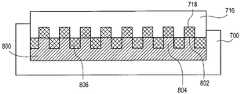
일 실시예에서, 제 2 혼합물(714)은 제 1 혼합물(706)과 상이하고, 제 1 혼합물(706)과 제 2 혼합물(714)을 완전히 경화시킬 때, 복수 개의 분리된 돌출부(718)들의 경도는 몰드성형된 균일체(708)의 경도와 상이하다. 일 실시예에서, 제 2 혼합물(714)을 적어도 부분적으로 경화시키는 단계는 복수 개의 분리된 돌출부(718)들을 몰드성형된 균일체(708)와 공유 결합시키는 단계를 포함한다. 일 실시예에서, 몰드성형된 균일체(708)를 형성하는 단계는 제 1 열경화성 폴리우레탄 재료를 형성하는 단계를 포함하고, 복수 개의 분리된 돌출부(718)들을 형성하는 단계는 상이한 제 2 열경화성 폴리우레탄 재료를 형성하는 단계를 포함한다.In one embodiment, the
도 7g를 참조하면, 연마 패드(720)는 균일체 상에 배치되는 복수 개의 분리된 돌출부(718)들을 가진 몰드성형된 균일체(708)를 성형 몰드(700)로부터 제거시 제공된다. 복수 개의 분리된 돌출부(718)들은 덮개(716)의 그루브들의 패턴에 대응하는 패턴을 가진다. 연마 패드(720)의 평면도는 도 7g의 아래에 나타나 있는 반면, b-b'축의 단면도는 도 7g의 위에 나타나 있다. 일 실시예에서, 몰드성형된 균일체(708)의 연마면(710)은 도 7g의 단면도에 도시되어 있는 바와 같이 실질적으로 편평하고, 복수 개의 분리된 돌출부(718)들 사이에 노출되어 있다.Referring to FIG. 7G, the
가열을 통하여 더 경화시키는 단계는 바람직할 수 있고, 연마 패드(720)를 오븐에 위치시켜서 가열함으로써 실행될 수 있다. 따라서, 일 실시예에서, 제 1 혼합물(706)과 제 2 혼합물(714)을 경화시키는 단계는 성형 몰드(700)에서 우선 부분적으로 경화시키는 단계 및 오븐 내에서 더 경화시키는 단계를 포함한다. 어떤 방법이든, 연마 패드(720)는 최종적으로 제공되고, 여기서 연마 패드(720)의 몰드성형된 균일체(708)는 균일체 상에 배치되는 복수 개의 몰드성형된 돌출부(718)들을 가진 연마면(710)을 가진다. 일 실시예에서, 몰드성형된 균일체(708)와 복수 개의 몰드성형된 돌출부(718)들 모두는 열경화성 폴리우레탄 재료들로 이루어지고, 복수 개의 폐포 기공들은 열경화성 폴리우레탄 재료들 내에 배치된다.Further curing through heating may be desirable and may be performed by placing the
도 7a 내지 도 7g와 함께 설명되는 것과 유사한 방식은 분리된 돌출부들을 그 위에 가지는 표면형상적으로 패턴이 형성된 균일체를 가진 연마 패드를 제조하는데 사용될 수 있다. 예를 들어, 도 8a 내지 도 8d에는 본 발명의 일 실시예에 따르는, 분리된 돌출부들을 그 위에 가지는 균일체를 가진 다른 연마 패드의 제조에 사용되는 공정의 단면도가 도시되어 있다.A manner similar to that described with FIGS. 7A-7G can be used to produce a polishing pad having a surface-shaped patterned uniform having separate protrusions thereon. For example, FIGS. 8A-8D illustrate cross-sectional views of a process used in the manufacture of another polishing pad having a uniform body having separate protrusions thereon, according to one embodiment of the present invention.
도 7c를 다시 참조한 다음 도 8a를 참조하면, 실질적으로 편평한 표면을 균일체(708)에 제공하기 위해서 제 1 혼합물(706)을 적어도 부분적으로 경화시키는 단계를 대신하여, 덮개(716)(도 7f와 함께 설명됨)는 덮개(716)의 그루브들의 패턴에 대응하는 패턴을 가진 복수 개의 돌출부(804)들을 가지는 연마면(802)을 가진 몰드성형된 균일체(800)를 우선 형성하는데 사용된다. 예를 들어, 제 1 혼합물(706)을 형성하기 위해서 제 1 프리-폴리머와 제 1 경화제를 혼합하는 단계 다음이지만 제 2 혼합물(714)을 형성하기 위해서 제 2 프리-폴리머와 제 2 경화제를 혼합하는 단계 이전에, 성형 몰드(700)의 덮개(716)는 제 1 혼합물(706) 속에 위치된다. 덮개가 제 1 혼합물(706) 내에 위치되는 상태에서, 제 1 혼합물(706)은 도 8b에 도시된 바와 같이 적어도 부분적으로 경화된다.Referring back to FIG. 7C and then to FIG. 8A, instead of at least partially curing the
도 8c를 참조하면, 제 2 프리-폴리머와 제 2 경화제는 몰드성형된 균일체(800) 상에 제 2 혼합물(714)을 형성하기 위해서 혼합된다. 그리고 나서 성형 몰드(700)의 덮개(716)는 도 8d에 도시된 바와 같이 제 2 혼합물(714) 속에 위치된다. 덮개(716)가 제 2 혼합물(714) 내에 위치되는 상태에서, 제 2 혼합물(714)은 적어도 부분적으로 경화되어, 몰드성형된 균일체(800)의 연마면(802)의 복수 개의 돌출부(804)들 상에 배치되고 이 돌출부들과 정렬되는 복수 개의 분리된 돌출부(718)들을 형성한다. 덮개(716)의 그루브들의 패턴은 성형 몰드(700) 내에서 제 2 혼합물(714)로부터 돌출부들의 패턴을 스탬핑처리하는데 사용된다. 그리고 나서 제 2 혼합물(714)은 몰드성형된 분리된 돌출부(718)들을 제공하기 위해서 압력 하에서(예컨대, 덮개(716)가 적소에 있는 상태) 가열될 수 있다. 일 실시예에서, 성형 몰드(700) 내에서 가열하는 단계는 덮개(716)가 존재하는 상태에서 적어도 부분적으로 경화시키는 단계를 포함하는데, 이 덮개는 제 2 혼합물(714)을 성형 몰드(700)에서 대략 2 내지 12 lb/in2 범위의 압력 및 대략 200 내지 260도의 화씨 온도 범위로 막는다. 따라서, 도 2와 함께 설명되는 연마 패드(200)와 같은 연마 패드는 형성될 수 있다.Referring to FIG. 8C, the second pre-polymer and the second curing agent are mixed to form a
다시 도 8d를 참조하면, 일 실시예에서, 몰드성형된 균일체(800) 상에 제 2 혼합물(714)을 형성하는 단계는, 몰드성형된 균일체(800) 상에 배치되는 충전층(806)을 형성하기에 충분히 큰 제 2 혼합물(714)의 양을 몰드성형된 균일체(800)의 연마면(802)의 복수 개의 돌출부(804)들 둘레에 형성하는 단계를 포함한다. 이러한 일 실시예에서, 제 2 혼합물(714)의 양은 제 2 혼합물(714)로부터 형성되는 복수 개의 분리된 돌출부(718)들과 불연속적인 충전층(806)을 형성하기에 충분히 적다. 이러한 불연속적인 예시는 도 2의 연마 패드(200)와 함께 상술되었다. 일 실시예에서, 회전판은 몰드성형된 균일체(800)의 연마면(802) 상에서 분배되는 제 2 혼합물(714)의 두께와 량을 제어하는데 사용된다.Referring again to FIG. 8D, in one embodiment, forming the
일 실시예에서, 복수 개의 분리된 돌출부(718)들은 몰드성형된 균일체(800)의 연마면(802)의 복수 개의 돌출부(804)들 상에 형성되고 이 돌출부들과 정렬된다. 이 정렬은 약간의 일부 정렬불량을 허용할 수 있다. 예를 들어, 대략 1 인치당 1/1,000까지의 범위의 오차(slippage)는 덮개(716)의 제 1 혼합물(706)과 제 2 혼합물(714) 각각으로의 개별적인 도입 사이에서 허용가능하다.In one embodiment, a plurality of
일 실시예에서, 도 7b를 참조하면, 혼합하는 단계는 폐포 기공들을 연마 패드의 최종적으로 형성된 연마체 내에 제공하기 위해서 복수 개의 포로겐(722)들을 프리-폴리머(702)와 경화제(704)에 첨가하는 단계를 더 포함한다. 따라서, 일 실시예에서, 폐포 기공 각각은 물리적인 셸을 가진다. 다른 실시예에서, 도 7b를 참조하면, 혼합하는 단계는 폐포 기공들을 연마 패드의 최종적으로 형성된 연마체 내에 제공하기 위해서 가스(724)를 프리-폴리머(702)와 경화제(704) 속으로 또는 프리-폴리머와 경화제로 형성된 생성물 속으로 분사하는 단계를 포함한다. 따라서, 일 실시예에서, 폐포 기공 각각은 물리적인 셸을 가지지 않는다. 조합의 일 실시예에서, 혼합하는 단계는 각각 물리적인 셸을 가지는 폐포 기공들의 제 1 부분을 제공하기 위해서 복수 개의 포로겐(722)들을 프리-폴리머(702)와 경화제(704)에 첨가하는 단계 및, 각각 물리적인 셸을 가지지 않는 폐포 기공들의 제 2 부분을 제공하기 위해서 가스(724)를 프리-폴리머(702)와 경화제(704) 속으로 또는 프리-폴리머와 경화제로부터 형성된 생성물 속으로 분사하는 단계를 더 포함한다. 또 다른 실시예에서, 프리-폴리머(702)는 이소시안산염이고, 혼합하는 단계는 각각 물리적인 셸을 가지지 않는 폐포 기공들을 제공하기 위해서 물(H2O)을 프리-폴리머(702)와 경화제(704)에 첨가하는 단계를 더 포함한다. 일 실시예에서, 도 7e와 도 8c를 참조하면, 복수 개의 포로겐들은 몰드성형된 복수 개의 분리된 돌출부(718)들 내에 유사하게 포함될 수 있다.In one embodiment, referring to FIG. 7B, the mixing step provides a plurality of
따라서, 본 발명의 실시예에서 고려되는 돌출부 패턴들은 인시츄 형성될 수 있다. 예를 들어, 상술된 바와 같이, 압축-몰딩 공정은 균일체 상에 배치되는 몰드성형된 분리된 돌출부들을 가지는 몰드성형된 균일체를 가진 연마 패드를 형성하는데 사용될 수 있다. 몰딩 공정을 사용함으로써, 패드 내부의 매우 균일한 돌출부 치수는 달성될 수 있다. 더욱이, 매우 연질의 깨끗한 돌출부 표면들과 함께 굉장히 반복생산가능한 돌출부 치수는 생성될 수 있다. 다른 이점들은 감소된 결점과 미세 스크래치 및 더 크게 사용가능한 돌출부 깊이를 포함할 수 있다.Therefore, the protrusion patterns considered in the embodiment of the present invention may be formed in situ. For example, as described above, a compression-molding process can be used to form a polishing pad having a molded homogeneous body with molded discrete protrusions disposed on the homogeneous body. By using a molding process, very uniform protrusion dimensions inside the pad can be achieved. Moreover, very reproducible protrusion dimensions can be created with very soft clean protrusion surfaces. Other advantages may include reduced defects and fine scratches and greater usable depth of protrusion.
여기에 설명되는 연마 패드는 여러 가지 화학적 기계적 연마 장치로 사용하는데 적합할 수 있다. 예시로서, 도 9에는 본 발명의 일 실시예에 따르는, 균일체 상의 분리된 돌출부들을 가지는 균일체를 가진 연마 패드와 함께 사용가능한 연마 장치의 등측도가 도시되어 있다.The polishing pads described herein may be suitable for use with various chemical mechanical polishing devices. By way of illustration, FIG. 9 shows an isometric view of a polishing apparatus usable with a polishing pad having a uniform having separate protrusions on the uniform, according to one embodiment of the invention.
도 9를 참조하면, 연마 장치(900)는 플래턴(904)을 포함한다. 플래턴(904)의 상면(902)은 분리된 돌출부들을 그 위에 가지는 균일체를 가진 연마 패드를 지지하는데 사용될 수 있다. 플래턴(904)은 스핀들 회전(906)과 슬라이더 요동(slider oscillation)(908)을 제공하도록 구성될 수 있다. 시료 운반장치(210)는, 예컨대 반도체 웨이퍼를 연마 패드로 연마하는 동안 반도체 웨이퍼(911)를 적소에 유지하는데 사용된다. 시료 운반장치(910)는 현가 장치(912)에 의해 더 지지된다. 슬러리 공급장치(914)는 반도체 웨이퍼의 연마 전과 이 연마 중에 슬러리를 연마 패드의 표면에 제공하기 위하여 포함된다. 컨디셔닝 유닛(990)도 포함될 수 있고, 일 실시예에서는 연마 패드의 컨디셔닝을 위한 다이아몬드 팁을 포함한다.Referring to FIG. 9, the polishing
이와 같이, 분리된 돌출부들을 그 위에 가지는 균일체들을 가진 연마 패드가 개시되어 있다. 본 발명의 일 실시예에 따르면, 기판을 연마하기 위한 연마 패드는 연마면과 후면을 가지는 균일체를 포함한다. 균일체는 제 1 경도를 가지는 재료로 이루어진다. 복수 개의 분리된 돌출부들은 균일체의 연마면 위에 배치되고 연마면과 공유 결합된다. 복수 개의 분리된 돌출부들은 제 1 경도와 상이한 제 2 경도를 가지는 재료로 이루어진다. 일 실시예에서, 균일체의 연마면은 실질적으로 편평하고 복수 개의 분리된 돌출부들 사이에 노출되어 있다. 일 실시예에서, 충전층은 균일체 상에서 균일체의 연마면의 복수 개의 돌출부들 둘레에 배치되고, 충전층은 복수 개의 분리된 돌출부들의 재료로 이루어진다. 일 실시예에서, 균일체는 몰드성형된 균일체이고, 복수 개의 분리된 돌출부들은 복수 개의 몰드성형된 돌출부들이다.As such, a polishing pad having homogeneous bodies having separated protrusions thereon is disclosed. According to one embodiment of the invention, a polishing pad for polishing a substrate comprises a uniform body having a polishing surface and a back surface. The homogeneous body is made of a material having a first hardness. The plurality of separate protrusions are disposed on the polishing surface of the uniform body and covalently bonded to the polishing surface. The plurality of separate protrusions are made of a material having a second hardness different from the first hardness. In one embodiment, the polishing surface of the uniform body is substantially flat and exposed between a plurality of separate protrusions. In one embodiment, the filling layer is disposed around the plurality of protrusions of the polishing surface of the homogeneous body on the uniform body, and the filling layer is made of a material of the plurality of separate protrusions. In one embodiment, the uniform is a molded uniform and the plurality of separate protrusions are a plurality of molded protrusions.
Claims (44)
Translated fromKorean연마면과 후면을 가지고, 제 1 경도를 가지는 재료를 구비하는 균일체; 및
상기 균일체의 연마면 상에 배치되고 상기 연마면과 공유 결합되고, 상기 제 1 경도와 상이한 제 2 경도를 가지는 재료를 구비하는 복수 개의 분리된 돌출부들;을 구비하는 것을 특징으로 하는 연마 패드.A polishing pad for polishing a substrate, the polishing pad comprising:
A uniform body having a polishing surface and a back surface and comprising a material having a first hardness; And
And a plurality of separate protrusions disposed on the polishing surface of the uniform body and covalently bonded to the polishing surface and having a material having a second hardness different from the first hardness.
상기 균일체의 연마면은 실질적으로 편평하고, 상기 복수 개의 분리된 돌출부들 사이에 노출되어 있는 것을 특징으로 하는 연마 패드.The method of claim 1,
And the polishing surface of the uniform body is substantially flat and is exposed between the plurality of separate protrusions.
상기 균일체는 몰드성형된 균일체이고,
상기 복수 개의 분리된 돌출부들은 복수 개의 몰드성형된 돌출부들인 것을 특징으로 하는 연마 패드.The method of claim 1,
The homogeneous is a molded homogeneous body,
And the plurality of separate protrusions are a plurality of molded molded protrusions.
상기 균일체의 재료는 제 1 열경화성 폴리우레탄 재료를 구비하고, 상기 복수 개의 분리된 돌출부들의 재료는 상이한 제 2 열경화성 폴리우레탄 재료를 구비하는 것을 특징으로 하는 연마 패드.The method of claim 1,
Wherein the material of the homogeneous material comprises a first thermosetting polyurethane material and the material of the plurality of separate protrusions comprises a different second thermosetting polyurethane material.
상기 균일체의 재료의 제 1 경도는 상기 복수 개의 분리된 돌출부들의 재료의 제 2 경도보다 작은 것을 특징으로 하는 연마 패드.The method of claim 1,
And the first hardness of the material of the homogeneous body is less than the second hardness of the material of the plurality of separate protrusions.
상기 제 1 경도는 대략 쇼어 경도 D 스케일로 40보다 작고, 상기 제 2 경도는 대략 쇼어 경도 D 스케일로 30보다 큰 것을 특징으로 하는 연마 패드.The method of claim 5, wherein
Wherein said first hardness is approximately less than 40 on Shore hardness D scale and said second hardness is greater than 30 on Shore hardness D scale.
상기 제 1 경도는 대략 쇼어 경도 D 스케일로 25보다 작고, 상기 제 2 경도는 대략 쇼어 경도 D 스케일로 40보다 큰 것을 특징으로 하는 연마 패드.The method according to claim 6,
Wherein the first hardness is less than 25 on the Shore hardness D scale and the second hardness is greater than 40 on the Shore hardness D scale.
상기 균일체의 재료의 제 1 경도는 상기 복수 개의 분리된 돌출부들의 재료의 제 2 경도보다 큰 것을 특징으로 하는 연마 패드.The method of claim 1,
And the first hardness of the material of the homogeneous body is greater than the second hardness of the material of the plurality of separate protrusions.
상기 제 2 경도는 대략 쇼어 경도 D 스케일로 40보다 작고, 상기 제 1 경도는 대략 쇼어 경도 D 스케일로 30보다 큰 것을 특징으로 하는 연마 패드.The method of claim 8,
And the second hardness is less than 40 on the Shore hardness D scale and the first hardness is greater than 30 on the Shore hardness D scale.
상기 제 2 경도는 대략 쇼어 경도 D 스케일로 25보다 작고, 상기 제 1 경도는 대략 쇼어 경도 D 스케일로 40보다 큰 것을 특징으로 하는 연마 패드.The method of claim 9,
And the second hardness is less than 25 on the Shore hardness D scale and the first hardness is greater than 40 on the Shore hardness D scale.
상기 균일체는 실질적으로 원형이고, 상기 복수 개의 분리된 돌출부들 중 하나 이상은 부분적으로 원주 상에 배치된 돌출부 또는 원호형상 돌출부인 것을 특징으로 하는 연마 패드.The method of claim 1,
And said uniform body is substantially circular, and at least one of said plurality of separate protrusions is a protrusion or arc-shaped protrusion partially disposed on a circumference.
상기 복수 개의 분리된 돌출부들은 원형 타일, 타원형 타일, 정사각형 타일, 육각형 타일 및 직사각형 타일로 이루어지는 그룹에서 선택되는 복수 개의 타일을 구비하는 것을 특징으로 하는 연마 패드.The method of claim 1,
And said plurality of separate protrusions comprises a plurality of tiles selected from the group consisting of circular tiles, oval tiles, square tiles, hexagonal tiles and rectangular tiles.
상기 복수 개의 분리된 돌출부들 각각은 상기 균일체의 연마면의 전체 평면 내에서 대략 5 내지 50mm 범위의 최단 치수를 가지는 것을 특징으로 하는 연마 패드.The method of claim 1,
And each of the plurality of separate protrusions has a shortest dimension in the range of approximately 5 to 50 mm in the entire plane of the polishing surface of the uniform body.
상기 균일체의 후면 내에 배치되는 탐지 영역을 더 구비하는 것을 특징으로 하는 연마 패드.The method of claim 1,
And a detection area disposed within the rear surface of the uniform body.
상기 균일체 내에 배치되는 국소 투명(LAT) 영역을 더 구비하는 것을 특징으로 하는 연마 패드.The method of claim 1,
And a localized transparent (LAT) region disposed within said uniform body.
패턴을 가지는 복수 개의 돌출부들을 구비하는 연마면과, 후면을 가지고, 제 1 경도를 가지는 재료를 구비하는 균일체;
상기 균일체의 연마면의 복수 개의 돌출부들 상에 배치되고 상기 돌출부들과 정렬되고, 상기 제 1 경도와 상이한 제 2 경도를 가지는 재료를 구비하며, 상기 패턴을 가지는 복수 개의 분리된 돌출부들; 및
상기 균일체의 연마면의 복수 개의 돌출부들 둘레에서 상기 균일체 상에 배치되고, 상기 복수 개의 분리된 돌출부들의 재료를 구비하는 충전층;을 구비하는 것을 특징으로 하는 연마 패드.A polishing pad for polishing a substrate, the polishing pad comprising:
A uniform body comprising a polishing surface having a plurality of protrusions having a pattern, and a material having a back surface and having a first hardness;
A plurality of separate protrusions disposed on the plurality of protrusions of the polishing surface of the uniform body and having a material having a second hardness different from the first hardness, the material having a pattern; And
And a filling layer disposed on the uniform body around the plurality of protrusions of the polishing surface of the uniform body and having a material of the plurality of separate protrusions.
상기 충전층은 상기 복수 개의 분리된 돌출부들과 불연속적인 것을 특징으로 하는 연마 패드.17. The method of claim 16,
And the filling layer is discontinuous with the plurality of separate protrusions.
상기 충전층과 상기 복수 개의 분리된 돌출부들 모두는 상기 균일체와 공유 결합되는 것을 특징으로 하는 연마 패드.17. The method of claim 16,
And both the filling layer and the plurality of separated protrusions are covalently bonded to the uniform body.
상기 균일체는 몰드성형된 균일체이고,
상기 복수 개의 분리된 돌출부들은 복수 개의 몰드성형된 돌출부들이며,
상기 충전층은 몰드성형된 충전층인 것을 특징으로 하는 연마 패드.17. The method of claim 16,
The homogeneous is a molded homogeneous body,
The plurality of separate protrusions are a plurality of molded molded protrusions,
And the filling layer is a molded filling layer.
상기 균일체의 재료는 제 1 열경화성 폴리우레탄 재료를 구비하고, 상기 복수 개의 분리된 돌출부들과 상기 충전층의 재료는 상이한 제 2 열경화성 폴리우레탄 재료를 구비하는 것을 특징으로 하는 연마 패드.17. The method of claim 16,
And wherein the material of the homogeneous body comprises a first thermosetting polyurethane material, and wherein the plurality of separate protrusions and the material of the filling layer comprise a second, different thermosetting polyurethane material.
상기 균일체의 재료의 제 1 경도는 상기 복수 개의 분리된 돌출부들과 상기 충전층의 재료의 제 2 경도보다 작은 것을 특징으로 하는 연마 패드.17. The method of claim 16,
And the first hardness of the material of the homogeneous body is smaller than the second hardness of the material of the plurality of separate protrusions and the filling layer.
상기 제 1 경도는 대략 쇼어 경도 D 스케일로 40보다 작고, 상기 제 2 경도는 대략 쇼어 경도 D 스케일로 30보다 큰 것을 특징으로 하는 연마 패드.22. The method of claim 21,
Wherein said first hardness is approximately less than 40 on Shore hardness D scale and said second hardness is greater than 30 on Shore hardness D scale.
상기 제 1 경도는 대략 쇼어 경도 D 스케일로 25보다 작고, 상기 제 2 경도는 대략 쇼어 경도 D 스케일로 40보다 큰 것을 특징으로 하는 연마 패드.23. The method of claim 22,
Wherein the first hardness is less than 25 on the Shore hardness D scale and the second hardness is greater than 40 on the Shore hardness D scale.
상기 균일체의 재료의 제 1 경도는 상기 복수 개의 분리된 돌출부들과 상기 충전층의 재료의 제 2 경도보다 큰 것을 특징으로 하는 연마 패드.17. The method of claim 16,
And a first hardness of the material of the homogeneous body is greater than a second hardness of the material of the plurality of separate protrusions and the filling layer.
상기 제 2 경도는 대략 쇼어 경도 D 스케일로 40보다 작고, 상기 제 1 경도는 대략 쇼어 경도 D 스케일로 30보다 큰 것을 특징으로 하는 연마 패드.25. The method of claim 24,
And the second hardness is less than 40 on the Shore hardness D scale and the first hardness is greater than 30 on the Shore hardness D scale.
상기 제 2 경도는 대략 쇼어 경도 D 스케일로 25보다 작고, 상기 제 1 경도는 대략 쇼어 경도 D 스케일로 40보다 큰 것을 특징으로 하는 연마 패드.The method of claim 25,
And the second hardness is less than 25 on the Shore hardness D scale and the first hardness is greater than 40 on the Shore hardness D scale.
상기 균일체는 실질적으로 원형이고, 상기 복수 개의 분리된 돌출부들 중 하나 이상은 부분적으로 원주 상에 배치된 돌출부 또는 원호형상 돌출부인 것을 특징으로 하는 연마 패드.17. The method of claim 16,
And said uniform body is substantially circular, and at least one of said plurality of separate protrusions is a protrusion or arc-shaped protrusion partially disposed on a circumference.
상기 복수 개의 분리된 돌출부들은 원형 타일, 타원형 타일, 정사각형 타일, 육각형 타일 및 직사각형 타일로 이루어지는 그룹에서 선택되는 복수 개의 타일을 구비하는 것을 특징으로 하는 연마 패드.17. The method of claim 16,
And said plurality of separate protrusions comprises a plurality of tiles selected from the group consisting of circular tiles, oval tiles, square tiles, hexagonal tiles and rectangular tiles.
상기 복수 개의 분리된 돌출부들 각각은 상기 균일체의 연마면의 전체 평면 내에서 대략 5 내지 50mm 범위의 최단 치수를 가지는 것을 특징으로 하는 연마 패드.17. The method of claim 16,
And each of the plurality of separate protrusions has a shortest dimension in the range of approximately 5 to 50 mm in the entire plane of the polishing surface of the uniform body.
상기 균일체의 후면 내에 배치되는 탐지 영역을 더 구비하는 것을 특징으로 하는 연마 패드.17. The method of claim 16,
And a detection area disposed within the rear surface of the uniform body.
상기 균일체 내에 배치되는 국소 투명(LAT) 영역을 더 구비하는 것을 특징으로 하는 연마 패드.17. The method of claim 16,
And a localized transparent (LAT) region disposed within said uniform body.
성형 몰드의 기저부 내에 제 1 혼합물을 형성하기 위해서 제 1 세트의 폴리머화가능한 재료들을 혼합하는 단계;
연마면과 후면을 가지는 몰드성형된 균일체를 형성하기 위해서 상기 제 1 혼합물을 적어도 부분적으로 경화시키는 단계;
제 2 혼합물을 상기 몰드성형된 균일체 상에 형성하기 위해서 제 2 세트의 폴리머화가능한 재료들을 혼합하는 단계;
상기 성형 몰드의 덮개를 상기 제 2 혼합물 속에 위치시켜, 상기 덮개가 그 위에 배치된 그루브들의 패턴을 가지게 하는 단계; 및
상기 덮개가 상기 제 2 혼합물 내에 위치되는 상태에서, 상기 제 2 혼합물을 적어도 부분적으로 경화시켜, 상기 몰드성형된 균일체의 연마면 상에 배치되고 상기 덮개의 상기 그루브들의 패턴에 대응하는 패턴을 가지는 복수 개의 분리된 돌출부들을 형성하는 단계;를 구비하는 것을 특징으로 하는 방법.A method of making a polishing pad for polishing a substrate, the method comprising:
Mixing the first set of polymerizable materials to form a first mixture in the base of the forming mold;
At least partially curing the first mixture to form a molded homogeneous body having a polishing surface and a back surface;
Mixing a second set of polymerizable materials to form a second mixture on the molded uniformed body;
Positioning a lid of the molding mold in the second mixture such that the lid has a pattern of grooves disposed thereon; And
With the lid positioned in the second mixture, the second mixture is at least partially cured to have a pattern disposed on the polishing surface of the molded uniform body and corresponding to the pattern of the grooves of the lid. Forming a plurality of separate protrusions.
상기 제 1 혼합물을 형성하기 위해서 상기 제 1 세트의 폴리머화가능한 재료들을 혼합하는 단계 다음이지만 상기 제 2 혼합물을 형성하기 위해서 상기 제 2 세트의 폴리머화가능한 재료들을 혼합하는 단계 이전에, 상기 성형 몰드의 덮개를 상기 제 1 혼합물 속에 위치시키는 단계; 및
상기 덮개가 상기 제 1 혼합물 내에 위치되는 상태에서, 상기 제 1 혼합물을 적어도 부분적으로 경화시키는 것을 실행하여, 상기 덮개의 상기 그루브들의 패턴에 대응하는 패턴을 가지는 복수 개의 돌출부들을 구비하는 상기 연마면을 가진 상기 몰드성형된 균일체를 형성하는 단계;를 더 구비하고,
상기 복수 개의 분리된 돌출부들은 상기 몰드성형된 균일체의 연마면의 복수 개의 돌출부들 상에 형성되고 상기 돌출부들과 정렬되는 것을 특징으로 하는 방법.33. The method of claim 32,
After the mixing of the first set of polymerizable materials to form the first mixture but before mixing the second set of polymerizable materials to form the second mixture, the molding mold Positioning a cover of the in the first mixture; And
With the lid positioned in the first mixture, performing at least partially curing of the first mixture to provide the polishing surface with a plurality of protrusions having a pattern corresponding to the pattern of the grooves of the lid. Forming the mold-formed homogeneous body having a further;
And the plurality of separate protrusions are formed on and aligned with the plurality of protrusions of the polishing surface of the molded uniform body.
상기 제 2 혼합물을 상기 몰드성형된 균일체 상에 형성하는 단계는, 상기 몰드성형된 균일체 상에 배치되는 충전층을 형성하기에 충분히 큰 제 2 혼합물의 양을 상기 몰드성형된 균일체의 연마면의 복수 개의 돌출부들 둘레에 형성하는 단계를 구비하고,
상기 제 2 혼합물의 양은 상기 제 2 혼합물로부터 형성된 상기 복수 개의 분리된 돌출부들과 불연속적인 상기 충전층을 형성하기에 충분히 작은 것을 특징으로 하는 방법.34. The method of claim 33,
The step of forming the second mixture on the molded homogenous is performed by polishing the amount of the second mixture large enough to form a packed layer disposed on the molded homogenous. Forming around a plurality of projections of the face,
Wherein the amount of the second mixture is small enough to form the packed layer discontinuous with the plurality of separate protrusions formed from the second mixture.
상기 제 1 세트의 폴리머화가능한 재료들은 제 1 프리-폴리머와 제 1 경화제를 구비하고, 상기 제 2 세트의 폴리머화가능한 재료들은 제 2 프리-폴리머와 제 2 경화제를 구비하는 것을 특징으로 하는 방법.33. The method of claim 32,
Wherein the first set of polymerizable materials comprises a first pre-polymer and a first curing agent, and the second set of polymerizable materials comprises a second pre-polymer and a second curing agent .
상기 몰드성형된 균일체의 연마면은 실질적으로 편평하고, 상기 복수 개의 분리된 돌출부들 사이에 노출되어 있는 것을 특징으로 하는 방법.33. The method of claim 32,
Wherein the polishing surface of the molded uniform body is substantially flat and is exposed between the plurality of separate protrusions.
상기 제 2 혼합물은 상기 제 1 혼합물과 상이하고,
상기 제 1 혼합물과 상기 제 2 혼합물을 완전히 경화시킬 때, 상기 복수 개의 분리된 돌출부들의 경도는 상기 몰드성형된 균일체의 경도와 상이한 것을 특징으로 하는 방법.33. The method of claim 32,
The second mixture is different from the first mixture,
When fully curing the first mixture and the second mixture, the hardness of the plurality of separate protrusions is different from the hardness of the molded uniform body.
상기 제 2 혼합물을 적어도 부분적으로 경화시키는 단계는 상기 복수 개의 분리된 돌출부들을 상기 몰드성형된 균일체와 공유 결합시키는 단계를 더 구비하는 것을 특징으로 하는 방법.33. The method of claim 32,
At least partially curing the second mixture further comprises covalently coupling the plurality of discrete protrusions with the molded homogeneous body.
상기 몰드성형된 균일체를 형성하는 단계는 제 1 열경화성 폴리우레탄 재료를 형성하는 단계를 구비하고, 상기 복수 개의 분리된 돌출부들을 형성하는 단계는 상이한 제 2 열경화성 폴리우레탄 재료를 형성하는 단계를 구비하는 것을 특징으로 하는 방법.33. The method of claim 32,
The forming of the molded homogeneous body includes forming a first thermosetting polyurethane material, and the forming of the plurality of separate protrusions comprises forming a different second thermosetting polyurethane material. Characterized in that the method.
상기 제 2 세트의 폴리머화가능한 재료들을 혼합하는 단계는, 복수 개의 포로겐들을 상기 제 2 세트의 폴리머화가능한 재료들에 첨가하여, 각각 물리적인 셸을 가지는 복수 개의 폐포 기공들을 상기 복수 개의 분리된 돌출부들 내에 형성하는 단계를 더 구비하는 것을 특징으로 하는 방법.33. The method of claim 32,
The mixing of the second set of polymerizable materials comprises adding a plurality of porogens to the second set of polymerizable materials, thereby producing a plurality of alveolar pores each having a physical shell. Forming in the protrusions.
상기 제 2 세트의 폴리머화가능한 재료를 혼합하는 단계는, 가스를 상기 제 2 세트의 폴리머화가능한 재료들 속으로 또는 그 재료들로부터 형성된 생성물 속으로 분사하여, 각각 물리적인 셸을 가지지 않는 복수 개의 폐포 기공들을 상기 복수 개의 분리된 돌출부들 내에 형성하는 단계를 더 구비하는 것을 특징으로 하는 방법.33. The method of claim 32,
Mixing the second set of polymerizable materials comprises spraying a gas into the second set of polymerizable materials or into a product formed from the materials, each having a plurality of physical shells without a physical shell. And forming alveolar pores in the plurality of discrete protrusions.
상기 제 2 세트의 폴리머화가능한 재료들을 혼합하는 단계는, 복수 개의 불투명한 분리된 돌출부들을 형성하기 위해서, 불투명 입자 충전재를 상기 제 2 세트의 폴리머화가능한 재료들에 첨가하는 단계를 더 구비하는 것을 특징으로 하는 방법.33. The method of claim 32,
Mixing the second set of polymerizable materials further comprises adding an opaque particle filler to the second set of polymerizable materials to form a plurality of opaque discrete protrusions. How to feature.
상기 복수 개의 분리된 돌출부들과 상기 몰드성형된 균일체를 오븐 내에서 경화시키는 단계를 더 구비하는 것을 특징으로 하는 방법.33. The method of claim 32,
And curing the plurality of separate protrusions and the molded uniform body in an oven.
상기 제 1 혼합물을 형성하기 위해서 상기 제 1 프리-폴리머와 상기 제 1 경화제를 혼합하는 단계는 상기 제 1 혼합물에서 가스를 제거하는 단계를 구비하고,
상기 제 2 혼합물을 형성하기 위해서 상기 제 2 프리-폴리머와 상기 제 2 경화제를 혼합하는 단계는 상기 제 2 혼합물에서 가스를 제거하는 단계를 구비하는 것을 특징으로 하는 방법.36. The method of claim 35,
Mixing the first pre-polymer and the first curing agent to form the first mixture comprises removing gas from the first mixture,
Mixing the second pre-polymer and the second curing agent to form the second mixture comprises removing gas from the second mixture.
Applications Claiming Priority (3)
| Application Number | Priority Date | Filing Date | Title |
|---|---|---|---|
| US13/113,655US20120302148A1 (en) | 2011-05-23 | 2011-05-23 | Polishing pad with homogeneous body having discrete protrusions thereon |
| US13/113,655 | 2011-05-23 | ||
| PCT/US2012/038212WO2012162066A1 (en) | 2011-05-23 | 2012-05-16 | Polishing pad with homogeneous body having discrete protrusions thereon |
Related Child Applications (1)
| Application Number | Title | Priority Date | Filing Date |
|---|---|---|---|
| KR1020157029108ADivisionKR101831909B1 (en) | 2011-05-23 | 2012-05-16 | Polishing pad with homogeneous body having discrete protrusions thereon |
Publications (2)
| Publication Number | Publication Date |
|---|---|
| KR20130138841Atrue KR20130138841A (en) | 2013-12-19 |
| KR101621789B1 KR101621789B1 (en) | 2016-05-17 |
Family
ID=46147792
Family Applications (2)
| Application Number | Title | Priority Date | Filing Date |
|---|---|---|---|
| KR1020137029736AActiveKR101621789B1 (en) | 2011-05-23 | 2012-05-16 | Polishing pad with homogeneous body having discrete protrusions thereon |
| KR1020157029108AActiveKR101831909B1 (en) | 2011-05-23 | 2012-05-16 | Polishing pad with homogeneous body having discrete protrusions thereon |
Family Applications After (1)
| Application Number | Title | Priority Date | Filing Date |
|---|---|---|---|
| KR1020157029108AActiveKR101831909B1 (en) | 2011-05-23 | 2012-05-16 | Polishing pad with homogeneous body having discrete protrusions thereon |
Country Status (7)
| Country | Link |
|---|---|
| US (2) | US20120302148A1 (en) |
| EP (2) | EP2857145B1 (en) |
| JP (3) | JP5657178B2 (en) |
| KR (2) | KR101621789B1 (en) |
| CN (1) | CN103561907B (en) |
| TW (2) | TWI504479B (en) |
| WO (1) | WO2012162066A1 (en) |
Cited By (13)
| Publication number | Priority date | Publication date | Assignee | Title |
|---|---|---|---|---|
| WO2016061544A1 (en)* | 2014-10-17 | 2016-04-21 | Applied Materials, Inc. | Polishing pads produced by an additive manufacturing process |
| JP2017510470A (en)* | 2014-04-03 | 2017-04-13 | スリーエム イノベイティブ プロパティズ カンパニー | Polishing pad and system, and method for making and using the same |
| US9776361B2 (en) | 2014-10-17 | 2017-10-03 | Applied Materials, Inc. | Polishing articles and integrated system and methods for manufacturing chemical mechanical polishing articles |
| US10384330B2 (en) | 2014-10-17 | 2019-08-20 | Applied Materials, Inc. | Polishing pads produced by an additive manufacturing process |
| US10391605B2 (en) | 2016-01-19 | 2019-08-27 | Applied Materials, Inc. | Method and apparatus for forming porous advanced polishing pads using an additive manufacturing process |
| US10399201B2 (en) | 2014-10-17 | 2019-09-03 | Applied Materials, Inc. | Advanced polishing pads having compositional gradients by use of an additive manufacturing process |
| US10821573B2 (en) | 2014-10-17 | 2020-11-03 | Applied Materials, Inc. | Polishing pads produced by an additive manufacturing process |
| US10875153B2 (en) | 2014-10-17 | 2020-12-29 | Applied Materials, Inc. | Advanced polishing pad materials and formulations |
| US10875145B2 (en) | 2014-10-17 | 2020-12-29 | Applied Materials, Inc. | Polishing pads produced by an additive manufacturing process |
| US11072050B2 (en) | 2017-08-04 | 2021-07-27 | Applied Materials, Inc. | Polishing pad with window and manufacturing methods thereof |
| US11471999B2 (en) | 2017-07-26 | 2022-10-18 | Applied Materials, Inc. | Integrated abrasive polishing pads and manufacturing methods |
| US11524384B2 (en) | 2017-08-07 | 2022-12-13 | Applied Materials, Inc. | Abrasive delivery polishing pads and manufacturing methods thereof |
| US11745302B2 (en) | 2014-10-17 | 2023-09-05 | Applied Materials, Inc. | Methods and precursor formulations for forming advanced polishing pads by use of an additive manufacturing process |
Families Citing this family (45)
| Publication number | Priority date | Publication date | Assignee | Title |
|---|---|---|---|---|
| US20120302148A1 (en) | 2011-05-23 | 2012-11-29 | Rajeev Bajaj | Polishing pad with homogeneous body having discrete protrusions thereon |
| WO2013042507A1 (en)* | 2011-09-22 | 2013-03-28 | 東洋ゴム工業株式会社 | Polishing pad |
| US9067297B2 (en) | 2011-11-29 | 2015-06-30 | Nexplanar Corporation | Polishing pad with foundation layer and polishing surface layer |
| KR101685678B1 (en)* | 2011-11-29 | 2016-12-12 | 넥스플래너 코퍼레이션 | Polishing pad with foundation layer and polishing surface layer |
| US9067298B2 (en)* | 2011-11-29 | 2015-06-30 | Nexplanar Corporation | Polishing pad with grooved foundation layer and polishing surface layer |
| US10722997B2 (en) | 2012-04-02 | 2020-07-28 | Thomas West, Inc. | Multilayer polishing pads made by the methods for centrifugal casting of polymer polish pads |
| US10022842B2 (en) | 2012-04-02 | 2018-07-17 | Thomas West, Inc. | Method and systems to control optical transmissivity of a polish pad material |
| SG11201406287QA (en)* | 2012-04-02 | 2014-11-27 | Thomas West Inc | Methods and systems for centrifugal casting of polymer polish pads and polishing pads made by the methods |
| US9597769B2 (en) | 2012-06-04 | 2017-03-21 | Nexplanar Corporation | Polishing pad with polishing surface layer having an aperture or opening above a transparent foundation layer |
| US9649742B2 (en)* | 2013-01-22 | 2017-05-16 | Nexplanar Corporation | Polishing pad having polishing surface with continuous protrusions |
| US10160092B2 (en)* | 2013-03-14 | 2018-12-25 | Cabot Microelectronics Corporation | Polishing pad having polishing surface with continuous protrusions having tapered sidewalls |
| US20150038066A1 (en)* | 2013-07-31 | 2015-02-05 | Nexplanar Corporation | Low density polishing pad |
| JP6295807B2 (en)* | 2014-04-28 | 2018-03-20 | 株式会社リコー | Polishing tool and polishing apparatus |
| US9238294B2 (en)* | 2014-06-18 | 2016-01-19 | Nexplanar Corporation | Polishing pad having porogens with liquid filler |
| US9649741B2 (en)* | 2014-07-07 | 2017-05-16 | Jh Rhodes Company, Inc. | Polishing material for polishing hard surfaces, media including the material, and methods of forming and using same |
| WO2016061585A1 (en)* | 2014-10-17 | 2016-04-21 | Applied Materials, Inc. | Polishing pads produced by an additive manufacturing process |
| JP6476924B2 (en) | 2015-01-30 | 2019-03-06 | 株式会社リコー | Polishing sheet, polishing tool, and polishing method |
| US10092998B2 (en)* | 2015-06-26 | 2018-10-09 | Rohm And Haas Electronic Materials Cmp Holdings, Inc. | Method of making composite polishing layer for chemical mechanical polishing pad |
| CN108136563A (en)* | 2015-07-30 | 2018-06-08 | Jh罗得股份有限公司 | It polymerize polishing material, the medium comprising polymerization polishing material and system and its formation and application method |
| CN108136568B (en)* | 2015-10-16 | 2020-10-09 | 应用材料公司 | Method and apparatus for forming advanced polishing pads using additive manufacturing processes |
| WO2017074773A1 (en)* | 2015-10-30 | 2017-05-04 | Applied Materials, Inc. | An apparatus and method of forming a polishing article that has a desired zeta potential |
| US10593574B2 (en) | 2015-11-06 | 2020-03-17 | Applied Materials, Inc. | Techniques for combining CMP process tracking data with 3D printed CMP consumables |
| CN105500183B (en)* | 2015-11-26 | 2018-08-10 | 上海集成电路研发中心有限公司 | A kind of grinding pad and its service life detection method |
| CN105598866B (en)* | 2015-12-28 | 2017-07-21 | 郑州磨料磨具磨削研究所有限公司 | A kind of manufacture method for electroplating extra hard material grinding wheel |
| WO2017127221A1 (en) | 2016-01-19 | 2017-07-27 | Applied Materials, Inc. | Porous chemical mechanical polishing pads |
| JP7193221B2 (en) | 2016-01-25 | 2022-12-20 | 富士紡ホールディングス株式会社 | Polishing pad, method for producing same, and method for producing abrasive product |
| TWI629297B (en)* | 2016-07-05 | 2018-07-11 | 智勝科技股份有限公司 | Polishing layer and method of forming the same and polishing method |
| US10195713B2 (en) | 2016-08-11 | 2019-02-05 | 3M Innovative Properties Company | Lapping pads and systems and methods of making and using the same |
| US10596763B2 (en) | 2017-04-21 | 2020-03-24 | Applied Materials, Inc. | Additive manufacturing with array of energy sources |
| AU2019200390B2 (en) | 2018-01-31 | 2024-04-11 | Dow Global Technologies Llc | Coating formulation with a poly(oxyalkylene-urethane) associative thickener modified with a hydrophobic oligomer |
| CN110815037B (en)* | 2018-08-08 | 2021-07-30 | 湖北鼎龙控股股份有限公司 | Polishing pad and preparation method and application thereof |
| CN112654655A (en) | 2018-09-04 | 2021-04-13 | 应用材料公司 | Advanced polishing pad formulations |
| CN108972319A (en)* | 2018-09-18 | 2018-12-11 | 长鑫存储技术有限公司 | Chemical and mechanical grinding cushion and preparation method thereof |
| US20200230781A1 (en)* | 2019-01-23 | 2020-07-23 | Applied Materials, Inc. | Polishing pads formed using an additive manufacturing process and methods related thereto |
| US11845157B2 (en)* | 2019-05-07 | 2023-12-19 | Cmc Materials, Inc. | Chemical mechanical planarization pads via vat-based production |
| CN110614580B (en)* | 2019-10-22 | 2021-11-19 | 西安奕斯伟材料科技有限公司 | Polishing pad, preparation method thereof and chemical mechanical polishing equipment |
| US11813712B2 (en) | 2019-12-20 | 2023-11-14 | Applied Materials, Inc. | Polishing pads having selectively arranged porosity |
| CN113070810A (en)* | 2020-01-03 | 2021-07-06 | 铨科光电材料股份有限公司 | Wafer polishing pad |
| US11806829B2 (en) | 2020-06-19 | 2023-11-07 | Applied Materials, Inc. | Advanced polishing pads and related polishing pad manufacturing methods |
| US11878389B2 (en) | 2021-02-10 | 2024-01-23 | Applied Materials, Inc. | Structures formed using an additive manufacturing process for regenerating surface texture in situ |
| KR20230106863A (en)* | 2022-01-07 | 2023-07-14 | 삼성전자주식회사 | Polishing pad, chemichal mechanical polishing apparatus including the same, and method for fabricating semiconductor device using the same |
| CN116922262A (en)* | 2022-06-09 | 2023-10-24 | 台湾积体电路制造股份有限公司 | Polishing pad for chemical mechanical polishing and method of forming same |
| US20240100648A1 (en)* | 2022-09-22 | 2024-03-28 | Cmc Materials Llc | Chemical mechanical polishing pads with a disulfide bridge |
| WO2024203831A1 (en)* | 2023-03-29 | 2024-10-03 | 富士紡ホールディングス株式会社 | Method for producing polishing pad |
| CN116652847A (en)* | 2023-04-26 | 2023-08-29 | 淮安市海达工程塑料有限公司 | MC nylon wheel with metal core and production process thereof |
Family Cites Families (69)
| Publication number | Priority date | Publication date | Assignee | Title |
|---|---|---|---|---|
| US1953983A (en)* | 1928-02-07 | 1934-04-10 | Carborundum Co | Manufacture of rubber bonded abrasive articles |
| JPS6179575A (en)* | 1984-09-25 | 1986-04-23 | Achilles Corp | Abrasive ground fabric and manufacturing method thereof |
| IE61697B1 (en) | 1987-12-22 | 1994-11-16 | De Beers Ind Diamond | Abrasive product |
| US5190568B1 (en) | 1989-01-30 | 1996-03-12 | Ultimate Abrasive Syst Inc | Abrasive tool with contoured surface |
| US5014468A (en)* | 1989-05-05 | 1991-05-14 | Norton Company | Patterned coated abrasive for fine surface finishing |
| US5177908A (en)* | 1990-01-22 | 1993-01-12 | Micron Technology, Inc. | Polishing pad |
| US5020283A (en)* | 1990-01-22 | 1991-06-04 | Micron Technology, Inc. | Polishing pad with uniform abrasion |
| US5212910A (en)* | 1991-07-09 | 1993-05-25 | Intel Corporation | Composite polishing pad for semiconductor process |
| KR0165625B1 (en)* | 1993-06-02 | 1999-02-01 | 기타지마 요시토시 | Grinding tape and method of manufacturing the grinding tape |
| US5453106A (en)* | 1993-10-27 | 1995-09-26 | Roberts; Ellis E. | Oriented particles in hard surfaces |
| US5391210A (en)* | 1993-12-16 | 1995-02-21 | Minnesota Mining And Manufacturing Company | Abrasive article |
| US5893796A (en)* | 1995-03-28 | 1999-04-13 | Applied Materials, Inc. | Forming a transparent window in a polishing pad for a chemical mechanical polishing apparatus |
| US5958794A (en)* | 1995-09-22 | 1999-09-28 | Minnesota Mining And Manufacturing Company | Method of modifying an exposed surface of a semiconductor wafer |
| US5609517A (en)* | 1995-11-20 | 1997-03-11 | International Business Machines Corporation | Composite polishing pad |
| US5624303A (en)* | 1996-01-22 | 1997-04-29 | Micron Technology, Inc. | Polishing pad and a method for making a polishing pad with covalently bonded particles |
| JPH106218A (en)* | 1996-06-27 | 1998-01-13 | Minnesota Mining & Mfg Co <3M> | Abrasive product for dressing |
| US6194317B1 (en)* | 1998-04-30 | 2001-02-27 | 3M Innovative Properties Company | Method of planarizing the upper surface of a semiconductor wafer |
| JP4151799B2 (en) | 1997-05-09 | 2008-09-17 | ローム アンド ハース エレクトロニック マテリアルズ シーエムピー ホウルディングス インコーポレイテッド | Mosaic polishing pad and related method |
| US5921855A (en) | 1997-05-15 | 1999-07-13 | Applied Materials, Inc. | Polishing pad having a grooved pattern for use in a chemical mechanical polishing system |
| JP2000033553A (en)* | 1998-05-11 | 2000-02-02 | Sony Corp | Polishing pad and polishing method |
| JP2918883B1 (en)* | 1998-07-15 | 1999-07-12 | 日本ピラー工業株式会社 | Polishing pad |
| US6299508B1 (en)* | 1998-08-05 | 2001-10-09 | 3M Innovative Properties Company | Abrasive article with integrally molded front surface protrusions containing a grinding aid and methods of making and using |
| US6183346B1 (en) | 1998-08-05 | 2001-02-06 | 3M Innovative Properties Company | Abrasive article with embossed isolation layer and methods of making and using |
| US6413153B1 (en)* | 1999-04-26 | 2002-07-02 | Beaver Creek Concepts Inc | Finishing element including discrete finishing members |
| US6179887B1 (en)* | 1999-02-17 | 2001-01-30 | 3M Innovative Properties Company | Method for making an abrasive article and abrasive articles thereof |
| US6217426B1 (en)* | 1999-04-06 | 2001-04-17 | Applied Materials, Inc. | CMP polishing pad |
| US6498101B1 (en)* | 2000-02-28 | 2002-12-24 | Micron Technology, Inc. | Planarizing pads, planarizing machines and methods for making and using planarizing pads in mechanical and chemical-mechanical planarization of microelectronic device substrate assemblies |
| US6454634B1 (en) | 2000-05-27 | 2002-09-24 | Rodel Holdings Inc. | Polishing pads for chemical mechanical planarization |
| US6736709B1 (en) | 2000-05-27 | 2004-05-18 | Rodel Holdings, Inc. | Grooved polishing pads for chemical mechanical planarization |
| US20030207659A1 (en)* | 2000-11-03 | 2003-11-06 | 3M Innovative Properties Company | Abrasive product and method of making and using the same |
| JP2002172563A (en) | 2000-11-24 | 2002-06-18 | Three M Innovative Properties Co | Abrasive tape |
| KR100905266B1 (en)* | 2000-12-01 | 2009-06-29 | 도요 고무 고교 가부시키가이샤 | Polishing pad |
| US6523215B2 (en)* | 2001-04-04 | 2003-02-25 | Saint-Gobain Abrasives Technology Company | Polishing pad and system |
| US6544373B2 (en)* | 2001-07-26 | 2003-04-08 | United Microelectronics Corp. | Polishing pad for a chemical mechanical polishing process |
| JP2003053657A (en)* | 2001-08-10 | 2003-02-26 | Ebara Corp | Polishing surface structural member and polishing device using the same |
| JP3851135B2 (en)* | 2001-10-17 | 2006-11-29 | ニッタ・ハース株式会社 | Polishing pad |
| US7399516B2 (en)* | 2002-05-23 | 2008-07-15 | Novellus Systems, Inc. | Long-life workpiece surface influencing device structure and manufacturing method |
| US8602851B2 (en) | 2003-06-09 | 2013-12-10 | Rohm And Haas Electronic Materials Cmp Holdings, Inc. | Controlled penetration subpad |
| US7201647B2 (en) | 2002-06-07 | 2007-04-10 | Praxair Technology, Inc. | Subpad having robust, sealed edges |
| US6838169B2 (en) | 2002-09-11 | 2005-01-04 | Psiloquest, Inc. | Polishing pad resistant to delamination |
| KR100465649B1 (en) | 2002-09-17 | 2005-01-13 | 한국포리올 주식회사 | Integral polishing pad and manufacturing method thereof |
| JP2004243428A (en)* | 2003-02-12 | 2004-09-02 | Rodel Nitta Co | Polishing pad |
| CN100548576C (en)* | 2003-04-25 | 2009-10-14 | Jsr株式会社 | Polishing pad and cmp method |
| US6884156B2 (en) | 2003-06-17 | 2005-04-26 | Cabot Microelectronics Corporation | Multi-layer polishing pad material for CMP |
| JP2005074614A (en)* | 2003-09-03 | 2005-03-24 | Nitta Haas Inc | Polishing pad and its manufacturing method |
| US7654885B2 (en)* | 2003-10-03 | 2010-02-02 | Applied Materials, Inc. | Multi-layer polishing pad |
| JP2005277130A (en)* | 2004-03-25 | 2005-10-06 | Fujitsu Ltd | Manufacturing method of semiconductor device |
| US7204742B2 (en)* | 2004-03-25 | 2007-04-17 | Cabot Microelectronics Corporation | Polishing pad comprising hydrophobic region and endpoint detection port |
| US7198549B2 (en) | 2004-06-16 | 2007-04-03 | Cabot Microelectronics Corporation | Continuous contour polishing of a multi-material surface |
| US7097542B2 (en)* | 2004-07-26 | 2006-08-29 | Intel Corporation | Method and apparatus for conditioning a polishing pad |
| JP2006140240A (en)* | 2004-11-11 | 2006-06-01 | Renesas Technology Corp | Polishing pad, polishing device, and method of manufacturing semiconductor device |
| US7530880B2 (en) | 2004-11-29 | 2009-05-12 | Semiquest Inc. | Method and apparatus for improved chemical mechanical planarization pad with pressure control and process monitor |
| US7846008B2 (en) | 2004-11-29 | 2010-12-07 | Semiquest Inc. | Method and apparatus for improved chemical mechanical planarization and CMP pad |
| US7169029B2 (en) | 2004-12-16 | 2007-01-30 | 3M Innovative Properties Company | Resilient structured sanding article |
| TWI385050B (en)* | 2005-02-18 | 2013-02-11 | Nexplanar Corp | Customized polishing pads for cmp and methods of fabrication and use thereof |
| JP4620501B2 (en)* | 2005-03-04 | 2011-01-26 | ニッタ・ハース株式会社 | Polishing pad |
| JP2006346805A (en)* | 2005-06-15 | 2006-12-28 | Toyo Tire & Rubber Co Ltd | Laminated polishing pad |
| JP4904027B2 (en)* | 2005-08-10 | 2012-03-28 | ニッタ・ハース株式会社 | Polishing pad |
| WO2007104063A1 (en)* | 2006-03-09 | 2007-09-13 | Rimpad Tech Ltd. | Composite polishing pad |
| US7235114B1 (en) | 2006-03-16 | 2007-06-26 | 3M Innovative Properties Company | Flexible abrasive article |
| US8083820B2 (en)* | 2006-12-22 | 2011-12-27 | 3M Innovative Properties Company | Structured fixed abrasive articles including surface treated nano-ceria filler, and method for making and using the same |
| JP5363470B2 (en)* | 2007-06-08 | 2013-12-11 | アプライド マテリアルズ インコーポレイテッド | Thin polishing pad with window and molding process |
| TWI388402B (en)* | 2007-12-06 | 2013-03-11 | Methods for orienting superabrasive particles on a surface and associated tools | |
| JP2010029996A (en)* | 2008-07-30 | 2010-02-12 | Toray Ind Inc | Polishing pad |
| US20100317262A1 (en)* | 2009-06-16 | 2010-12-16 | Zine-Eddine Boutaghou | Abrasive article with uniform height abrasive particles |
| JP5728026B2 (en)* | 2009-12-22 | 2015-06-03 | スリーエム イノベイティブ プロパティズ カンパニー | Polishing pad and method of manufacturing the same |
| CN101823242B (en)* | 2010-04-29 | 2012-06-06 | 沈阳理工大学 | Bionic polishing pad based on sunflower kernel distribution structure and manufacturing method |
| US20120302148A1 (en) | 2011-05-23 | 2012-11-29 | Rajeev Bajaj | Polishing pad with homogeneous body having discrete protrusions thereon |
| US9067297B2 (en) | 2011-11-29 | 2015-06-30 | Nexplanar Corporation | Polishing pad with foundation layer and polishing surface layer |
- 2011
- 2011-05-23USUS13/113,655patent/US20120302148A1/ennot_activeAbandoned
- 2012
- 2012-05-16KRKR1020137029736Apatent/KR101621789B1/enactiveActive
- 2012-05-16JPJP2014511502Apatent/JP5657178B2/enactiveActive
- 2012-05-16EPEP14198969.9Apatent/EP2857145B1/enactiveActive
- 2012-05-16WOPCT/US2012/038212patent/WO2012162066A1/enunknown
- 2012-05-16EPEP12723065.4Apatent/EP2714331B1/enactiveActive
- 2012-05-16KRKR1020157029108Apatent/KR101831909B1/enactiveActive
- 2012-05-16CNCN201280024792.5Apatent/CN103561907B/enactiveActive
- 2012-05-22TWTW101118247Apatent/TWI504479B/enactive
- 2012-05-22TWTW104123294Apatent/TWI630067B/enactive
- 2014
- 2014-10-14JPJP2014209683Apatent/JP5965453B2/enactiveActive
- 2014-10-31USUS14/530,534patent/US9296085B2/enactiveActive
- 2016
- 2016-04-19JPJP2016083450Apatent/JP6309559B2/enactiveActive
Cited By (23)
| Publication number | Priority date | Publication date | Assignee | Title |
|---|---|---|---|---|
| JP2017513722A (en)* | 2014-04-03 | 2017-06-01 | スリーエム イノベイティブ プロパティズ カンパニー | Polishing pad and system, and method for making and using the same |
| JP2017510470A (en)* | 2014-04-03 | 2017-04-13 | スリーエム イノベイティブ プロパティズ カンパニー | Polishing pad and system, and method for making and using the same |
| US10821573B2 (en) | 2014-10-17 | 2020-11-03 | Applied Materials, Inc. | Polishing pads produced by an additive manufacturing process |
| US10953515B2 (en) | 2014-10-17 | 2021-03-23 | Applied Materials, Inc. | Apparatus and method of forming a polishing pads by use of an additive manufacturing process |
| US9873180B2 (en) | 2014-10-17 | 2018-01-23 | Applied Materials, Inc. | CMP pad construction with composite material properties using additive manufacturing processes |
| US10384330B2 (en) | 2014-10-17 | 2019-08-20 | Applied Materials, Inc. | Polishing pads produced by an additive manufacturing process |
| US12023853B2 (en) | 2014-10-17 | 2024-07-02 | Applied Materials, Inc. | Polishing articles and integrated system and methods for manufacturing chemical mechanical polishing articles |
| US10399201B2 (en) | 2014-10-17 | 2019-09-03 | Applied Materials, Inc. | Advanced polishing pads having compositional gradients by use of an additive manufacturing process |
| US10493691B2 (en) | 2014-10-17 | 2019-12-03 | Applied Materials, Inc. | Polishing articles and integrated system and methods for manufacturing chemical mechanical polishing articles |
| US10537974B2 (en) | 2014-10-17 | 2020-01-21 | Applied Materials, Inc. | CMP pad construction with composite material properties using additive manufacturing processes |
| WO2016061544A1 (en)* | 2014-10-17 | 2016-04-21 | Applied Materials, Inc. | Polishing pads produced by an additive manufacturing process |
| US10875153B2 (en) | 2014-10-17 | 2020-12-29 | Applied Materials, Inc. | Advanced polishing pad materials and formulations |
| US10875145B2 (en) | 2014-10-17 | 2020-12-29 | Applied Materials, Inc. | Polishing pads produced by an additive manufacturing process |
| US9776361B2 (en) | 2014-10-17 | 2017-10-03 | Applied Materials, Inc. | Polishing articles and integrated system and methods for manufacturing chemical mechanical polishing articles |
| US11958162B2 (en) | 2014-10-17 | 2024-04-16 | Applied Materials, Inc. | CMP pad construction with composite material properties using additive manufacturing processes |
| US11446788B2 (en) | 2014-10-17 | 2022-09-20 | Applied Materials, Inc. | Precursor formulations for polishing pads produced by an additive manufacturing process |
| US11745302B2 (en) | 2014-10-17 | 2023-09-05 | Applied Materials, Inc. | Methods and precursor formulations for forming advanced polishing pads by use of an additive manufacturing process |
| KR20220146708A (en)* | 2014-10-17 | 2022-11-01 | 어플라이드 머티어리얼스, 인코포레이티드 | Polishing pads produced by an additive manufacturing process |
| US11724362B2 (en) | 2014-10-17 | 2023-08-15 | Applied Materials, Inc. | Polishing pads produced by an additive manufacturing process |
| US10391605B2 (en) | 2016-01-19 | 2019-08-27 | Applied Materials, Inc. | Method and apparatus for forming porous advanced polishing pads using an additive manufacturing process |
| US11471999B2 (en) | 2017-07-26 | 2022-10-18 | Applied Materials, Inc. | Integrated abrasive polishing pads and manufacturing methods |
| US11072050B2 (en) | 2017-08-04 | 2021-07-27 | Applied Materials, Inc. | Polishing pad with window and manufacturing methods thereof |
| US11524384B2 (en) | 2017-08-07 | 2022-12-13 | Applied Materials, Inc. | Abrasive delivery polishing pads and manufacturing methods thereof |
Also Published As
| Publication number | Publication date |
|---|---|
| JP2015006731A (en) | 2015-01-15 |
| TWI630067B (en) | 2018-07-21 |
| US9296085B2 (en) | 2016-03-29 |
| EP2714331A1 (en) | 2014-04-09 |
| EP2714331B1 (en) | 2015-04-01 |
| US20120302148A1 (en) | 2012-11-29 |
| KR101621789B1 (en) | 2016-05-17 |
| WO2012162066A1 (en) | 2012-11-29 |
| EP2857145A1 (en) | 2015-04-08 |
| KR101831909B1 (en) | 2018-02-26 |
| CN103561907A (en) | 2014-02-05 |
| JP2014515319A (en) | 2014-06-30 |
| TW201538274A (en) | 2015-10-16 |
| TWI504479B (en) | 2015-10-21 |
| EP2857145B1 (en) | 2018-12-26 |
| CN103561907B (en) | 2017-05-31 |
| JP5657178B2 (en) | 2015-01-21 |
| KR20150122806A (en) | 2015-11-02 |
| US20150056900A1 (en) | 2015-02-26 |
| JP2016135542A (en) | 2016-07-28 |
| TW201309419A (en) | 2013-03-01 |
| JP5965453B2 (en) | 2016-08-03 |
| JP6309559B2 (en) | 2018-04-11 |
Similar Documents
| Publication | Publication Date | Title |
|---|---|---|
| KR20130138841A (en) | Polishing pad with homogeneous body having discrete protrusions thereon | |
| CN104105575B (en) | Polishing pad with base layer and polishing surface layer | |
| US9931728B2 (en) | Polishing pad with foundation layer and polishing surface layer | |
| TWI533368B (en) | Polishing pad with multi-modal distribution of pore diameters | |
| TWI554364B (en) | Polishing pad with polishing surface layer having an aperture or opening above a transparent foundation layer | |
| US9067298B2 (en) | Polishing pad with grooved foundation layer and polishing surface layer |
Legal Events
| Date | Code | Title | Description |
|---|---|---|---|
| A201 | Request for examination | ||
| PA0105 | International application | Patent event date:20131108 Patent event code:PA01051R01D Comment text:International Patent Application | |
| PA0201 | Request for examination | ||
| PG1501 | Laying open of application | ||
| E902 | Notification of reason for refusal | ||
| PE0902 | Notice of grounds for rejection | Comment text:Notification of reason for refusal Patent event date:20150227 Patent event code:PE09021S01D | |
| AMND | Amendment | ||
| E601 | Decision to refuse application | ||
| PE0601 | Decision on rejection of patent | Patent event date:20150914 Comment text:Decision to Refuse Application Patent event code:PE06012S01D Patent event date:20150227 Comment text:Notification of reason for refusal Patent event code:PE06011S01I | |
| X091 | Application refused [patent] | ||
| A107 | Divisional application of patent | ||
| AMND | Amendment | ||
| PA0104 | Divisional application for international application | Comment text:Divisional Application for International Patent Patent event code:PA01041R01D Patent event date:20151013 | |
| PX0901 | Re-examination | Patent event code:PX09011S01I Patent event date:20150914 Comment text:Decision to Refuse Application Patent event code:PX09012R01I Patent event date:20150527 Comment text:Amendment to Specification, etc. | |
| E902 | Notification of reason for refusal | ||
| PE0902 | Notice of grounds for rejection | Comment text:Notification of reason for refusal Patent event date:20151119 Patent event code:PE09021S01D | |
| AMND | Amendment | ||
| PX0701 | Decision of registration after re-examination | Patent event date:20160224 Comment text:Decision to Grant Registration Patent event code:PX07013S01D Patent event date:20160217 Comment text:Amendment to Specification, etc. Patent event code:PX07012R01I Patent event date:20151013 Comment text:Amendment to Specification, etc. Patent event code:PX07012R01I Patent event date:20150914 Comment text:Decision to Refuse Application Patent event code:PX07011S01I Patent event date:20150527 Comment text:Amendment to Specification, etc. Patent event code:PX07012R01I | |
| X701 | Decision to grant (after re-examination) | ||
| GRNT | Written decision to grant | ||
| PR0701 | Registration of establishment | Comment text:Registration of Establishment Patent event date:20160511 Patent event code:PR07011E01D | |
| PR1002 | Payment of registration fee | Payment date:20160512 End annual number:3 Start annual number:1 | |
| PG1601 | Publication of registration | ||
| FPAY | Annual fee payment | Payment date:20190429 Year of fee payment:4 | |
| PR1001 | Payment of annual fee | Payment date:20190429 Start annual number:4 End annual number:4 | |
| PR1001 | Payment of annual fee | Payment date:20200324 Start annual number:5 End annual number:5 | |
| PR1001 | Payment of annual fee | Payment date:20210329 Start annual number:6 End annual number:6 | |
| PR1001 | Payment of annual fee | Payment date:20230327 Start annual number:8 End annual number:8 | |
| PR1001 | Payment of annual fee | Payment date:20240424 Start annual number:9 End annual number:9 |