KR20130136921A - Asymmetric eptfe membrane - Google Patents
Asymmetric eptfe membraneDownload PDFInfo
- Publication number
- KR20130136921A KR20130136921AKR1020130063240AKR20130063240AKR20130136921AKR 20130136921 AKR20130136921 AKR 20130136921AKR 1020130063240 AKR1020130063240 AKR 1020130063240AKR 20130063240 AKR20130063240 AKR 20130063240AKR 20130136921 AKR20130136921 AKR 20130136921A
- Authority
- KR
- South Korea
- Prior art keywords
- microporous membrane
- membrane
- hydrophilic
- liquid
- hydrophobic
- Prior art date
- Legal status (The legal status is an assumption and is not a legal conclusion. Google has not performed a legal analysis and makes no representation as to the accuracy of the status listed.)
- Withdrawn
Links
- 239000012528membraneSubstances0.000titleclaimsabstractdescription58
- 239000012982microporous membraneSubstances0.000claimsabstractdescription172
- 239000007788liquidSubstances0.000claimsabstractdescription108
- 230000002209hydrophobic effectEffects0.000claimsabstractdescription57
- 238000004821distillationMethods0.000claimsabstractdescription44
- 238000000034methodMethods0.000claimsabstractdescription31
- 238000010438heat treatmentMethods0.000claimsabstractdescription7
- 239000011248coating agentSubstances0.000claimsdescription17
- 238000000576coating methodMethods0.000claimsdescription17
- 239000011148porous materialSubstances0.000claimsdescription13
- 238000009792diffusion processMethods0.000claimsdescription11
- 229920000295expanded polytetrafluoroethylenePolymers0.000claimsdescription7
- -1polytetrafluoroethylenePolymers0.000claimsdescription6
- 238000004519manufacturing processMethods0.000claimsdescription5
- 239000002033PVDF binderSubstances0.000claimsdescription4
- 239000004743PolypropyleneSubstances0.000claimsdescription4
- 125000003055glycidyl groupChemical groupC(C1CO1)*0.000claimsdescription4
- 229920001155polypropylenePolymers0.000claimsdescription4
- 229920002981polyvinylidene fluoridePolymers0.000claimsdescription4
- 229920001343polytetrafluoroethylenePolymers0.000claimsdescription3
- 239000004810polytetrafluoroethyleneSubstances0.000claimsdescription3
- HRPVXLWXLXDGHG-UHFFFAOYSA-NAcrylamideChemical groupNC(=O)C=CHRPVXLWXLXDGHG-UHFFFAOYSA-N0.000claims3
- NIXOWILDQLNWCW-UHFFFAOYSA-Macrylate groupChemical groupC(C=C)(=O)[O-]NIXOWILDQLNWCW-UHFFFAOYSA-M0.000claims3
- NIXOWILDQLNWCW-UHFFFAOYSA-Nacrylic acid groupChemical groupC(C=C)(=O)ONIXOWILDQLNWCW-UHFFFAOYSA-N0.000claims3
- XLYOFNOQVPJJNP-UHFFFAOYSA-NwaterChemical compoundOXLYOFNOQVPJJNP-UHFFFAOYSA-N0.000description12
- 238000001816coolingMethods0.000description6
- 239000002918waste heatSubstances0.000description6
- 239000000835fiberSubstances0.000description5
- 239000000463materialSubstances0.000description5
- KFZMGEQAYNKOFK-UHFFFAOYSA-NIsopropanolChemical compoundCC(C)OKFZMGEQAYNKOFK-UHFFFAOYSA-N0.000description3
- 238000011109contaminationMethods0.000description3
- 239000012466permeateSubstances0.000description3
- 239000002904solventSubstances0.000description3
- 239000000758substrateSubstances0.000description3
- 239000012080ambient airSubstances0.000description2
- 230000004888barrier functionEffects0.000description2
- 238000004891communicationMethods0.000description2
- 238000009833condensationMethods0.000description2
- 230000005494condensationEffects0.000description2
- 238000010586diagramMethods0.000description2
- 239000012530fluidSubstances0.000description2
- 239000007789gasSubstances0.000description2
- 230000000717retained effectEffects0.000description2
- 238000009736wettingMethods0.000description2
- 241000894006BacteriaSpecies0.000description1
- HGCIXCUEYOPUTN-UHFFFAOYSA-NC1CC=CCC1Chemical compoundC1CC=CCC1HGCIXCUEYOPUTN-UHFFFAOYSA-N0.000description1
- 229920000742CottonPolymers0.000description1
- LFQSCWFLJHTTHZ-UHFFFAOYSA-NEthanolChemical compoundCCOLFQSCWFLJHTTHZ-UHFFFAOYSA-N0.000description1
- CBENFWSGALASAD-UHFFFAOYSA-NOzoneChemical compound[O-][O+]=OCBENFWSGALASAD-UHFFFAOYSA-N0.000description1
- 239000002202Polyethylene glycolSubstances0.000description1
- 238000009825accumulationMethods0.000description1
- 150000001298alcoholsChemical class0.000description1
- 230000003373anti-fouling effectEffects0.000description1
- 239000007864aqueous solutionSubstances0.000description1
- 239000000470constituentSubstances0.000description1
- 239000000356contaminantSubstances0.000description1
- 239000013505freshwaterSubstances0.000description1
- 238000003306harvestingMethods0.000description1
- CERQOIWHTDAKMF-UHFFFAOYSA-Mmethacrylate groupChemical groupC(C(=C)C)(=O)[O-]CERQOIWHTDAKMF-UHFFFAOYSA-M0.000description1
- 239000012229microporous materialSubstances0.000description1
- 238000012986modificationMethods0.000description1
- 230000004048modificationEffects0.000description1
- 229920001223polyethylene glycolPolymers0.000description1
- 229920002451polyvinyl alcoholPolymers0.000description1
- 235000019422polyvinyl alcoholNutrition0.000description1
- 230000002265preventionEffects0.000description1
- 238000000746purificationMethods0.000description1
- 150000003839saltsChemical class0.000description1
- 239000013535sea waterSubstances0.000description1
- 238000000926separation methodMethods0.000description1
- 239000007787solidSubstances0.000description1
- 239000000243solutionSubstances0.000description1
- 238000003860storageMethods0.000description1
- 238000002834transmittanceMethods0.000description1
- 239000011800void materialSubstances0.000description1
Images


Classifications
- B—PERFORMING OPERATIONS; TRANSPORTING
- B01—PHYSICAL OR CHEMICAL PROCESSES OR APPARATUS IN GENERAL
- B01D—SEPARATION
- B01D61/00—Processes of separation using semi-permeable membranes, e.g. dialysis, osmosis or ultrafiltration; Apparatus, accessories or auxiliary operations specially adapted therefor
- B01D61/36—Pervaporation; Membrane distillation; Liquid permeation
- B01D61/364—Membrane distillation
- B—PERFORMING OPERATIONS; TRANSPORTING
- B01—PHYSICAL OR CHEMICAL PROCESSES OR APPARATUS IN GENERAL
- B01D—SEPARATION
- B01D61/00—Processes of separation using semi-permeable membranes, e.g. dialysis, osmosis or ultrafiltration; Apparatus, accessories or auxiliary operations specially adapted therefor
- B01D61/36—Pervaporation; Membrane distillation; Liquid permeation
- B01D61/368—Accessories; Auxiliary operations
- B—PERFORMING OPERATIONS; TRANSPORTING
- B01—PHYSICAL OR CHEMICAL PROCESSES OR APPARATUS IN GENERAL
- B01D—SEPARATION
- B01D67/00—Processes specially adapted for manufacturing semi-permeable membranes for separation processes or apparatus
- B01D67/0002—Organic membrane manufacture
- B01D67/0023—Organic membrane manufacture by inducing porosity into non porous precursor membranes
- B01D67/0025—Organic membrane manufacture by inducing porosity into non porous precursor membranes by mechanical treatment, e.g. pore-stretching
- B01D67/0027—Organic membrane manufacture by inducing porosity into non porous precursor membranes by mechanical treatment, e.g. pore-stretching by stretching
- B—PERFORMING OPERATIONS; TRANSPORTING
- B01—PHYSICAL OR CHEMICAL PROCESSES OR APPARATUS IN GENERAL
- B01D—SEPARATION
- B01D67/00—Processes specially adapted for manufacturing semi-permeable membranes for separation processes or apparatus
- B01D67/0081—After-treatment of organic or inorganic membranes
- B01D67/0088—Physical treatment with compounds, e.g. swelling, coating or impregnation
- B—PERFORMING OPERATIONS; TRANSPORTING
- B01—PHYSICAL OR CHEMICAL PROCESSES OR APPARATUS IN GENERAL
- B01D—SEPARATION
- B01D67/00—Processes specially adapted for manufacturing semi-permeable membranes for separation processes or apparatus
- B01D67/0081—After-treatment of organic or inorganic membranes
- B01D67/009—After-treatment of organic or inorganic membranes with wave-energy, particle-radiation or plasma
- B—PERFORMING OPERATIONS; TRANSPORTING
- B01—PHYSICAL OR CHEMICAL PROCESSES OR APPARATUS IN GENERAL
- B01D—SEPARATION
- B01D69/00—Semi-permeable membranes for separation processes or apparatus characterised by their form, structure or properties; Manufacturing processes specially adapted therefor
- B01D69/12—Composite membranes; Ultra-thin membranes
- B01D69/1213—Laminated layers
- B—PERFORMING OPERATIONS; TRANSPORTING
- B01—PHYSICAL OR CHEMICAL PROCESSES OR APPARATUS IN GENERAL
- B01D—SEPARATION
- B01D71/00—Semi-permeable membranes for separation processes or apparatus characterised by the material; Manufacturing processes specially adapted therefor
- B01D71/06—Organic material
- B01D71/30—Polyalkenyl halides
- B01D71/32—Polyalkenyl halides containing fluorine atoms
- B01D71/36—Polytetrafluoroethene
- C—CHEMISTRY; METALLURGY
- C02—TREATMENT OF WATER, WASTE WATER, SEWAGE, OR SLUDGE
- C02F—TREATMENT OF WATER, WASTE WATER, SEWAGE, OR SLUDGE
- C02F1/00—Treatment of water, waste water, or sewage
- C02F1/44—Treatment of water, waste water, or sewage by dialysis, osmosis or reverse osmosis
- C02F1/447—Treatment of water, waste water, or sewage by dialysis, osmosis or reverse osmosis by membrane distillation
- B—PERFORMING OPERATIONS; TRANSPORTING
- B01—PHYSICAL OR CHEMICAL PROCESSES OR APPARATUS IN GENERAL
- B01D—SEPARATION
- B01D2313/00—Details relating to membrane modules or apparatus
- B01D2313/22—Cooling or heating elements
- B—PERFORMING OPERATIONS; TRANSPORTING
- B01—PHYSICAL OR CHEMICAL PROCESSES OR APPARATUS IN GENERAL
- B01D—SEPARATION
- B01D2323/00—Details relating to membrane preparation
- B01D2323/02—Hydrophilization
- B—PERFORMING OPERATIONS; TRANSPORTING
- B01—PHYSICAL OR CHEMICAL PROCESSES OR APPARATUS IN GENERAL
- B01D—SEPARATION
- B01D2325/00—Details relating to properties of membranes
- B01D2325/02—Details relating to pores or porosity of the membranes
- B01D2325/022—Asymmetric membranes
- B—PERFORMING OPERATIONS; TRANSPORTING
- B01—PHYSICAL OR CHEMICAL PROCESSES OR APPARATUS IN GENERAL
- B01D—SEPARATION
- B01D2325/00—Details relating to properties of membranes
- B01D2325/36—Hydrophilic membranes
- B—PERFORMING OPERATIONS; TRANSPORTING
- B01—PHYSICAL OR CHEMICAL PROCESSES OR APPARATUS IN GENERAL
- B01D—SEPARATION
- B01D2325/00—Details relating to properties of membranes
- B01D2325/38—Hydrophobic membranes
Landscapes
- Chemical & Material Sciences (AREA)
- Engineering & Computer Science (AREA)
- Chemical Kinetics & Catalysis (AREA)
- Water Supply & Treatment (AREA)
- Manufacturing & Machinery (AREA)
- Inorganic Chemistry (AREA)
- Physics & Mathematics (AREA)
- Plasma & Fusion (AREA)
- Life Sciences & Earth Sciences (AREA)
- Organic Chemistry (AREA)
- Environmental & Geological Engineering (AREA)
- Hydrology & Water Resources (AREA)
- Separation Using Semi-Permeable Membranes (AREA)
- Laminated Bodies (AREA)
Abstract
Translated fromKoreanDescription
Translated fromKorean본 발명은 일반적으로 액체 증류, 더욱 구체적으로는 비대칭 팽창 폴리테트라플루오로에틸렌(ePTFE) 막을 사용하는 액체 증류에 관한 것이다.
The present invention relates generally to liquid distillation, more particularly to liquid distillation using asymmetric expanded polytetrafluoroethylene (ePTFE) membranes.
증기-투과성 액체-불투과성 미세다공성 막은 공지되어 있고 다수의 상이한 용도에 사용되고 있다. 이러한 미세다공성 막은 예를 들어 액체를 증류하기 위한 막 증류 시스템에 사용된다. 간략하게 요약하자면, 막 증류 시스템은 증류되지 않은 액체를 가열하기 위한 폐열을 혼입할 수 있고, 이 때 가열된 증류되지 않은 액체는 미세다공성 막으로 전달된다. 증류되지 않은 액체로부터의 증기는 미세다공성 막을 통해 통과하며, 이어 증기는 응축되어 증류된 액체가 된다. 과거에는, 이러한 막 증류 시스템에 완전히 소수성인 막을 사용해왔다. 유사하게, 소수성 막의 하나 이상의 표면 상에 경계 층을 제공하여 오염(fouling)에 대한 저항성을 개선한다. 그러나, 증기가 먼저 경계 층을 통해 통과한 다음 완전히 소수성인 막을 통해 투과되어야 하기 때문에, 경계 층을 갖는 이들 완전히 소수성인 막을 통한 확산은 비교적 느리다. 막 증류 시스템의 완전히 소수성인 막은 약 5 내지 60l/m2/시간 같은, 바람직한 수증기 투과 유량 미만의 수증기 투과 유량을 나타내고, 내부 공극의 습윤을 통해 오염되기 쉽다.
Vapor-permeable liquid-impermeable microporous membranes are known and used for many different applications. Such microporous membranes are used, for example, in membrane distillation systems for distilling liquids. In summary, the membrane distillation system may incorporate waste heat to heat the undistilled liquid, where the heated undistilled liquid is transferred to the microporous membrane. Vapor from the undistilled liquid passes through the microporous membrane, which then condenses to a distilled liquid. In the past, membranes that are completely hydrophobic have been used in such membrane distillation systems. Similarly, providing a boundary layer on one or more surfaces of the hydrophobic film improves resistance to fouling. However, diffusion through these fully hydrophobic membranes with a boundary layer is relatively slow because the vapor must first pass through the boundary layer and then permeate through the fully hydrophobic membrane. The fully hydrophobic membrane of the membrane distillation system exhibits a water vapor permeation flow rate below the desired water vapor permeation flow rate, such as about 5 to 60 l / m2 / hour, and is prone to contamination through the wetting of the internal pores.
따라서, 증가된 수증기 투과 유량 및 개선된 오염 저항성을 갖는 미세다공성 막을 사용하는 막 증류 시스템을 제공하는 것이 유용할 것이다.
Thus, it would be useful to provide membrane distillation systems using microporous membranes with increased water vapor permeate flow rates and improved contamination resistance.
하기는 본 발명의 몇몇 예시적인 양상에 대한 기본적인 이해를 제공하기 위하여 본 발명의 간단한 요약을 기술한다. 이 요약은 본 발명의 광범위한 개관이 아니다. 뿐만 아니라, 이 요약은 본 발명의 결정적인 요소를 밝히는 것도 아니고 본 발명의 영역을 기술하는 것도 아니다. 이 요약의 유일한 목적은 이후 기술되는 더욱 상세한 설명에 대한 서문으로서 간략화된 형태로 본 발명의 몇몇 개념을 기술하기 위한 것이다.The following describes a brief summary of the invention in order to provide a basic understanding of some exemplary aspects of the invention. This summary is not an extensive overview of the invention. In addition, this summary does not identify critical elements of the present invention nor does it describe the scope of the present invention. Its sole purpose is to present some concepts of the invention in a simplified form as a prelude to the more detailed description that is presented later.
한 양태에 따라, 본 발명은 액체를 증류하기 위한 막 증류 시스템을 제공한다. 막 증류 시스템은 증류되지 않은 액체를 가열하기 위한 발열 수단을 포함한다. 막 증류 시스템은 또한 비대칭이고 증기 투과성인 미세다공성 막을 포함하며, 이 때 미세다공성 막은 친수성 층 및 소수성 층을 포함한다. 막 증류 시스템은 가열된 증류되지 않은 액체를 미세다공성 막의 친수성 층에 전달하기 위한 공급 수단, 및 미세다공성 막의 소수성 층으로부터 증류된 액체를 수거하기 위한 수거 수단을 추가로 포함한다.According to one aspect, the present invention provides a membrane distillation system for distilling a liquid. The membrane distillation system includes exothermic means for heating the liquid that is not distilled. The membrane distillation system also includes an asymmetric and vapor permeable microporous membrane, wherein the microporous membrane comprises a hydrophilic layer and a hydrophobic layer. The membrane distillation system further comprises supply means for delivering the heated undistilled liquid to the hydrophilic layer of the microporous membrane, and harvesting means for collecting the distilled liquid from the hydrophobic layer of the microporous membrane.
다른 양태에 따라, 본 발명은 액체를 증류하기 위한, 증기 투과성인 미세다공성 막을 제공한다. 막은 미세다공성 막의 제 1 면에 제공되는 친수성 층을 포함한다. 미세다공성 막은 미세다공성 막의 반대쪽 제 2 면에 제공되는 소수성 층을 추가로 포함한다. 미세다공성 막의 제 1 면은 미세다공성 막의 제 2 면에 대해 비대칭이다.According to another aspect, the invention provides a vapor permeable microporous membrane for distilling a liquid. The membrane includes a hydrophilic layer provided on the first side of the microporous membrane. The microporous membrane further comprises a hydrophobic layer provided on the second opposite side of the microporous membrane. The first side of the microporous membrane is asymmetrical with respect to the second side of the microporous membrane.
다른 양태에 따라, 본 발명은 막 증류 시스템에 사용하기 위한, 증기 투과성인 미세다공성 막을 제조하는 방법을 제공한다. 이 방법은 소수성 미세다공성 막을 제공하는 단계를 포함한다. 방법은 또한 소수성 미세다공성 막의 제 1 면을 에너지원으로 처리하고, 제 1 면을 친수성 잔기로 코팅하여 친수성 잔기를 제 1 면에 공유 결합시키는 단계를 포함한다. 이로써, 소수성 미세다공성 막의 제 1 면은 친수성이고, 제 2 면은 소수성이다.
According to another aspect, the present invention provides a method of making a vapor permeable microporous membrane for use in a membrane distillation system. The method includes providing a hydrophobic microporous membrane. The method also includes treating the first side of the hydrophobic microporous membrane with an energy source and coating the first side with a hydrophilic residue to covalently bond the hydrophilic residue to the first side. As a result, the first side of the hydrophobic microporous membrane is hydrophilic and the second side is hydrophobic.
본 발명의 상기 양태 및 다른 양태는 첨부 도면을 참조하여 하기 설명을 읽을 때 본 발명이 속하는 기술 분야의 당 업자에게 명확해질 것이다.
도 1은 본 발명의 한 양태에 따른 예시적인 막 증류 시스템의 개략도이다.
도 2는 도 1의 막 증류 시스템에 사용하기 위한 예시적인 미세다공성 막의 개략도이며, 이 때 미세다공성 막은 반대쪽 소수성 층에 대해 비대칭인 친수성 층을 갖는다.
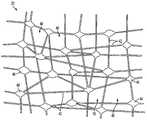
도 3은 도 1의 막 증류 시스템 내의 미세다공성 막의 일부의 확대 개략도이며, 결절에서 연결되는 소섬유에 의해 한정되는 개방된 미시적인 공극을 보여준다.
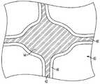
도 4는 도 3의 일부의 추가 확대도이며, 기재를 포함하는 미세다공성 막의 구성 부재를 보여주는데, 미세다공성 막의 공극을 차단하지 않는 친수성 잔기 코팅이 기재에 접착되어 있다.These and other aspects of the invention will become apparent to those skilled in the art upon reading the following description with reference to the accompanying drawings.
1 is a schematic of an exemplary membrane distillation system in accordance with an aspect of the present invention.
FIG. 2 is a schematic diagram of an exemplary microporous membrane for use in the membrane distillation system of FIG. 1, wherein the microporous membrane has a hydrophilic layer that is asymmetrical to the opposite hydrophobic layer.
FIG. 3 is an enlarged schematic view of a portion of the microporous membrane in the membrane distillation system of FIG. 1, showing open microscopic pores defined by small fibers connected in a nodule.
4 is a further enlarged view of a portion of FIG. 3, showing a constituent member of the microporous membrane comprising the substrate, wherein a hydrophilic residue coating is adhered to the substrate that does not block the pores of the microporous membrane.
본 발명의 하나 이상의 양태를 혼입하는 예시적인 실시양태가 기재되고 도면에 도시된다. 이들 도시된 예는 본 발명을 한정하고자 하지 않는다. 예를 들면, 본 발명의 하나 이상의 양태를 다른 실시양태에, 심지어는 다른 유형의 장치에 사용할 수 있다. 뿐만 아니라, 특정 용어를 본원에서는 편의상으로만 사용하고, 본 발명을 한정하고자 채택하지는 않는다. 또한, 도면에서는 동일한 요소를 지칭하기 위하여 동일한 참조 번호를 사용한다.Exemplary embodiments incorporating one or more aspects of the invention are described and illustrated in the drawings. These illustrated examples are not intended to limit the invention. For example, one or more aspects of the present invention can be used in other embodiments, even in other types of devices. In addition, certain terms are used herein for convenience only and are not employed to limit the invention. In the drawings, like reference numerals are used to refer to like elements.
도 1은 본 발명의 한 양태에 따른 예시적인 막 증류 시스템(10)의 개략도를 도시한다. 간략한 개요에서, 막 증류 시스템(10)은 증류되지 않은 액체(14)를 여과하여 증류된 액체(26)를 수득하는 미세다공성 막(20)을 포함한다. 미세다공성 막(20)은 친수성 층(30)을 포함하는 제 1 면(21)(도 2) 및 소수성 층(32)을 포함하는 반대쪽 제 2 면(22)을 포함할 수 있다. 증류되지 않은 액체(14)는 미세다공성 막(20)의 제 1 면(21)으로 전달되는데, 이 때 증류되지 않은 액체(14)로부터의 증기는 친수성 층 및 소수성 층을 통해 제 2 면(22)까지 통과한다. 이어, 증기는 응축되어 증류된 액체(26)가 된다. 이후 상세하게 기재되는 바와 같이, 미세다공성 막(20)은 한 면에 친수성 층(30)을 갖고 반대쪽 면에 소수성 층(32)을 가짐으로써 비대칭이다. 비대칭임으로써, 미세다공성 막(20)은 증가된 물 투과 유량 및 오염 저항성을 나타낸다.1 shows a schematic diagram of an exemplary
도 1의 막 증류 시스템(10)이 예시 목적을 위해 다소 포괄적으로/개략적으로 도시됨을 알아야 한다. 막 증류 시스템(10)을 다수의 산업 용도에 사용할 수 있다. 산업 용도는 하나 이상의 액체로부터의 오염물질의 분리(예컨대, 정수를 위해)를 포함할 수 있으나, 이것으로 한정되지는 않는다. 다른 예에서, 막 증류 시스템(10)은 공장, 온천, 태양광 에너지 구역 등을 비롯한(이들로 국한되지는 않음), 산업 공정으로부터의 과량의 폐열을 갖는 다수의 장소에 사용될 수 있다. 발전소, 핵 반응기 등과 같은 다른 장소에도 막 증류 시스템(10)을 설치할 수 있음을 알아야 한다.It should be noted that the
막 증류 시스템(10)은 발열 수단(12)을 포함한다. 발열 수단(12)이 다수의 상이한 구조체를 포함할 수 있기 때문에, 발열 수단(12)은 도 1에 개략적으로 도시된다. 발열 수단(12)은 증류되지 않은 액체(14)를 비교적 고온으로 유지시킨다. 발열 수단(12)은 예를 들어 상기 언급된 산업 공정으로부터 발생되는 폐열, 저등급 열 등을 포함할 수 있다. 한 예에서, 발열 수단(12)은 발전소로부터의 폐열, 태양광 에너지, 지열 에너지 등을 포함할 수 있다. 물론, 발열 수단(12)이 상기 언급된 예로 한정되지 않으며, 열을 생성시켜 증류되지 않은 액체(14)를 가온하는 임의의 유형의 구조체 또는 공정을 포함할 수 있음을 알아야 한다. 추가적인 예에서, 발열 수단(12)은 폐열로 한정되지 않으며, 또한 버너, 보일러, 열 교환기 등과 같은 열을 생성시키는 다양한 구조체도 포함할 수 있다.The
막 증류 시스템(10)은 증류되지 않은 액체(14)를 추가로 포함한다. 증류되지 않은 액체(14)는 발열 수단(12)에 의해 가열된다. 증류되지 않은 액체(14)는 임의의 수의 상이한 액체를 포함할 수 있다. 예를 들어, 증류되지 않은 액체(14)는 해수, 기수, 담수 또는 임의의 다른 유형의 오염된/여과되지 않은 물 같은 증류되지 않고/않거나 순수하지 않은 액체를 포함할 수 있다. 다른 예에서, 증류되지 않은 액체(14)는 유체(예컨대, 물)로 한정되지 않으며, 반고체 액체 등과 같은 액체와 고체의 조합을 포함할 수 있다. 실제로, 증류되지 않은 액체(14)는 용질, 용해된 기체, 염, 미립자 등을 비롯한(이들로 국한되지는 않음) 바람직하지 못한 성분을 함유할 수 있는 다수의 상이한 액체 또는 반고체 액체를 포함할 수 있다. 증류되지 않은 액체(14)는 산업 공정 부근에 위치될 수 있다. 예를 들어, 증류되지 않은 액체(14)는 바다, 호수, 연못, 늪 등과 같은 물 집단 근처에서 발견될 수 있다. 일반적으로 알려져 있는 바와 같이, 증류되지 않은 액체(14)는 탱크, 저장고 등과 같은 저장 수단 내에 함유될 수 있다.The
막 증류 시스템(10)은 증류되지 않은 액체(14)를 미세다공성 막(20)으로 공급하기 위한 공급 수단(16)을 추가로 포함한다. 공급 수단(16)이 증류되지 않은 액체(14)를 미세다공성 막(20)으로 전달하는 기능을 하는 다수의 상이한 구조체를 포함할 수 있기 때문에, 공급 수단(16)은 도 1에서 다소 포괄적으로 도시된다. 예를 들어, 공급 수단(16)은 액체를 한 장소에서 다른 장소로 수송하는데 사용될 수 있는 임의의 수의 상이한 파이프, 튜브, 펌프 및/또는 다른 장치를 포함할 수 있다. 추가적인 예에서, 공급 수단(16)은 또한 증류되지 않은 액체(14)의 미세다공성 막(20)으로의 유속을 제어하기 위한 밸브, 유량계 등도 포함할 수 있다. 증류되지 않은 액체(14)가 미세다공성 막(20)에 도달하기 전에 파이프, 튜브 또는 다른 장치로부터 보유 탱크 내로 유동될 수 있도록, 보유 탱크 또는 용기(도시되지 않음)가 공급 수단(16)과 유체 연통되어 제공될 수 있다. 물론, 공급 수단(16)이 증류되지 않은 액체(14)를 미세다공성 막(20)에 공급하기 위한 상기 언급된 품목의 임의의 조합을 포함할 수 있음을 알아야 한다.The
막 증류 시스템(10)은 미세다공성 막(20)을 또한 포함한다. 일반적으로, 미세다공성 막(20)은 두 액체 집단(각각의 집단은 상이한 온도로 유지됨, 즉 온도 구배)을 분리하는 증기 투과성-액체 불투과성 막을 포함할 수 있다. 미세다공성 막(20)을 가로지르는 이 온도 구배는 제 1 면(21)[예를 들어, 증류되지 않은 액체(14)에 인접함] 및 반대쪽 제 2 면(22) 사이에 증기압 차이를 생성시킨다. 미세다공성 막(20)의 제 1 면(21)과 제 2 면(22) 사이의 온도 차이는 압력 차이를 전달할 수 있으며, 이 압력 차이는 제 1 면(21)의 증기가 미세다공성 막(20)을 통해 투과되어 더욱 차가운 제 2 면(22)에서 응축되도록 한다. 이로써, 증기는 미세다공성 막(20)을 통해 통과할 수 있고, 미세다공성 막(20)의 더욱 따뜻한 제 1 면(21)으로부터 더욱 차가운 제 2 면(22)으로의 최종적인 순수한 액체 유동을 생성시킬 수 있다. 미세다공성 막(20)을 가로지르는 막 증류 공정은 세 가지 기본적인 단계로 기재될 수 있다. 첫째, 증류되지 않은 액체(14)를 보다 높은 온도로 유지하여, 이 액체가 미세다공성 막(20)의 제 1 면(21)에 도달할 때 이 액체를 증발시킨다. 둘째, 증기가 미세다공성 막(20)을 통해 투과된다. 마지막으로, 증기가 미세다공성 막(20)의 제 2 면(22)에서 나갈 때 응축이 일어날 수 있다.
막 증류 시스템(10)은 미세다공성 막(20)의 제 2 면(22)으로부터 증류된 액체(26)를 수거하기 위한 수거 수단(24)을 또한 포함할 수 있다. 도 1에 포괄적으로/개략적으로 도시된 수거 수단(24)은 공급 수단(16)과 유사하고/하거나 동일한 구조체 및 장치를 포함할 수 있다. 예를 들어, 수거 수단(24)은 증류된 액체(26)를 수거하고/하거나 하나의 장소[예컨대, 미세다공성 막(20)의 제 2 면(22)]로부터 다른 장소로 수송하는데 사용될 수 있는 파이프, 튜브, 펌프 및/또는 다른 장치(들)를 포함할 수 있다. 유사하게, 수거 수단(24)은 또한 미세다공성 막(20)으로부터의 증류된 액체(26)의 유속을 제어하기 위한 밸브, 유량계 등도 포함할 수 있다. 한 예에서, 수거 수단(24)은 튜브, 파이프 등에 의해 멀리 수송되기 전에 증류된 액체(26)가 유동되어 들어가는 보유 탱크 또는 용기(도시되지 않음)를 포함한다. 물론, 수거 수단(24)이 증류된 액체(26)를 수거하기 위한 상기 언급된 품목의 임의의 조합을 포함할 수 있음을 알아야 한다.
막 증류 시스템(10)은 증류된 액체(26)를 증류되지 않은 액체(14)보다 더 낮은 온도로 유지하기 위한 냉각 수단(28)을 추가로 포함할 수 있다. 증류된 액체(26)를 더 낮은 온도로 유지함으로써, 미세다공성 막(20)을 가로질러 온도 구배가 형성된다. 이 온도 구배는 미세다공성 막(20)을 통해 증기가 수송되도록 할 수 있다. 한 예에서는, 냉각 수단(28)이 주위 공기를 포함할 수 있도록, 제 2 면(22)에서의 주위 공기의 온도가 미세다공성 막(20)의 제 1 면(21)으로 공급되는 증류되지 않은 액체(14)의 온도 미만이다. 다른 예에서, 냉각 수단(28)은 증류된 액체(26)의 온도를 낮출 수 있는 구조체 및/또는 장치를 포함한다. 예를 들면, 냉각 수단(28)은 응축기, 냉각기, 열 교환기 등을 포함할 수 있다. 다른 예에서는, 주위 온도가 증류되지 않은 액체(14)의 온도보다 더 낮더라도, 냉각 수단(28)을 제공하여 미세다공성 막(20)을 가로지르는 증류된 액체(26)의 최종적인 유동을 야기하기에 충분한 온도 구배를 생성시킬 수 있다.The
도 2를 참조하면, 미세다공성 막(20)이 더욱 상세하게 기재되어 있다. 도 2에 도시된 미세다공성 막(20)이 예시 목적을 위해 다소 포괄적으로 도시되어 있음을 알아야 한다. 실제로, 다른 예에서, 미세다공성 막(20)은 도시된 것보다 더 길거나 더 작은 단면 폭을 가질 수 있다. 따라서, 미세다공성 막(20)이 다양한 상이한 치수를 포함할 수 있기 때문에, 도 2에 도시된 미세다공성 막(20)은 한 가지 가능한 예만을 포함한다.2, the
미세다공성 막(20)은 증기 투과성이고 액체 불투과성인 임의의 수의 상이한 소수성 물질을 포함할 수 있다. 한 예에서, 미세다공성 막(20)은 팽창 폴리테트라플루오로에틸렌(ePTFE)을 포함할 수 있다. 그러나, 다른 예에서, 미세다공성 막(20)은 그를 통한 증기의 통과는 허용하면서 액체에는 반발하는 다른 미세다공성 물질을 포함할 수 있다. 미세다공성 막(20)은 폴리테트라플루오로에틸렌(eTFE), 폴리비닐리덴 플루오라이드(PVDF), 폴리프로필렌(PP) 등을 추가로 포함할 수 있다. 이로써, 미세다공성 막(20)이 본원에 나열된 예로 한정되지 않으며 다른 소수성 물질을 포함할 수 있음을 알아야 한다.
미세다공성 막(20)은 제 1 면(21)과 반대쪽 제 2 면(22) 사이에서 연장된다. 제 1 면(21)은 막 증류 시스템(10)의 증류되지 않은 액체에 인접하여 위치하는 반면, 제 2 면(22)은 증류된 액체 면에 인접하여 위치된다. 제 1 면(21)은 증류되지 않은 액체(14)를 수용할 수 있다(도 2에서 모여진 액체 대형으로서 포괄적으로 도시됨). 유사하게, 증류된 액체(26)는 제 2 면(22)으로부터 수거될 수 있다(도 2에서 액체의 소적으로 포괄적으로 도시됨). 물론, 도 2의 증류되지 않은 액체(14) 및 증류된 액체(26)가 예시 목적으로 포괄적으로 도시되고, 추가의 예에서는 각각 도시된 것보다 더 많은 액체 또는 더 적은 액체를 포함할 수 있음을 알아야 한다.The
미세다공성 막(20)을 처리하여, 미세다공성 막(20)의 일부를 친수성으로 만들 수 있다. 한 예에서는, 미세다공성 막(20)의 제 1 면(21)을 처리하고 친수성으로 만들 수 있는 반면, 미세다공성 막(20)의 제 2 면(22)은 소수성으로 유지된다. 이로써, 미세다공성 막(20)의 일부는 친수성인 반면, 미세다공성 막(20)의 나머지는 소수성이다. 아래에 기재되는 바와 같이, 임의의 수의 방식으로 미세다공성 막(20)을 처리하여 제 1 면(21)을 친수성으로 만들 수 있다.By treating the
이제, 미세다공성 막(20)을 처리하는 제 1 방법을 기재한다. 미세다공성 막(20)을 처리하는 제 1 방법은 미세다공성 막(20)을 에너지원으로 미리 처리하는 제 1 단계 후, 미세다공성 막(20)을 친수성 잔기로 코팅하는 제 2 단계를 포함할 수 있다. 원래, 미세다공성 막(20)은 실질적으로 또는 완전히 소수성일 수 있다. 제 1 단계에서는, 미세다공성 막(20)의 제 1 면(21)을 먼저 에너지원으로 미리 처리할 수 있다. 이들 에너지원은 고주파 글로우 방전 플라즈마, 저압 극초단파 방전, 오전 등을 포함하지만, 이들로 한정되지는 않는다. 추가적인 예에서는, 미세다공성 막(20)의 제 1 면(21)을 약 50W 내지 약 150W의 H2 플라즈마에 노출시킬 수 있다. 미세다공성 막(20)을 이들 에너지원으로 처리하면, 미세다공성 막(20)의 비교적 강한 탄소-플루오르 결합이 절단되어 자유 라디칼을 발생시킬 수 있다.Now, a first method of treating the
미세다공성 막(20)을 에너지원으로 미리 처리하는 제 1 단계 후에, 미세다공성 막(20)을 제 2 단계에서 친수성 잔기로 추가로 처리할 수 있다. 구체적으로, 미세다공성 막(20)의 제 1 면(21)을 에너지원으로 미리 처리한 후, 이어 제 1 면(21)을 친수성 잔기로 처리한다. 친수성 잔기를 미세다공성 막(20)의 자유 라디칼에 그라프팅시켜 공유 결합을 형성시킬 수 있다. 한 예에서, 친수성 잔기는 폴리에틸렌-글라이콜 메타크릴레이트(수용액중 5% 내지 25%)를 비롯한(이것으로 국한되지는 않음) 글라이시딜-펜던트 기를 포함할 수 있다. 글라이시딜 펜던트 기를 약 50℃ 내지 약 70℃에서 약 4시간 내지 약 7시간동안 플라즈마-처리된 기재에 반응시킬 수 있다. 친수성 잔기를 사용한 이 처리 후, 미세다공성 막(20)의 제 1 면(21)은 친수성으로 되고 친수성 층(30)을 형성한다. 미세다공성 막(20)의 제 2 면(22)은 소수성으로 남아 있고 소수성 층(32)을 포함한다.After the first step of pretreating the
미세다공성 막(20)이 상기 기재된 제 1 처리 방법으로 한정되는 것은 아님을 알아야 한다. 구체적으로, 미세다공성 막(20)은 미세다공성 막(20)의 일부를 친수성이 되게 하기 위한 상기 기재된 제 1 방법으로 한정되지는 않는다. 대신, 이제 미세다공성 막(20)을 처리하는 제 2 방법을 기재한다.It should be noted that the
제 2 방법에서는, 미세다공성 막(20)을 친수성으로 만드는 상기 언급된 단계(예컨대, 에너지원으로 먼저 미리 처리한 후 친수성 잔기를 그라프팅시킴)를 반대로 진행시킬 수 있다. 예를 들면, 미세다공성 막(20)을 먼저 친수성 잔기로 코팅할 수 있다. 구체적으로는, 미세다공성 막(20)의 제 1 면(21)을 친수성 잔기로 코팅하고/하거나 침착시킬 수 있다. 이 예에서는, 물 및 알콜(예컨대, 아이소프로필 알콜)을 비롯한 용매가 제공된다. 물 대 알콜 부피비는 표적 용액 표면 장력이 약 30다인/cm 내지 약 50다인/cm가 되도록 하는 것일 수 있다. 친수성 잔기는 용매 중에 제공될 수 있다. 용매 중의 친수성 잔기는 메타크릴레이트 측쇄와 연결된 폴리비닐-알콜을 포함할 수 있으나, 이것으로 국한되지는 않는다.In a second method, the above-mentioned steps of making the
미세다공성 막(20)의 제 1 면(21)을 친수성 잔기로 코팅하는 제 1 단계 후, 이어 제 1 면(21)을 처리 에너지원에 노출시킬 수 있다. 한 예에서는, 제 1 면(21)을 처리 에너지원에 노출시켜, 라디칼을 형성시키고, 친수성 잔기를 미세다공성 막(20)의 주쇄에 공유 결합시킨다. 처리 에너지원은 한 예에서 약 5kGy 내지 약 15kGy의 조사량의 e-빔을 포함한다. 물론, 임의의 수의 상이한 처리 에너지원이 계획됨을 알아야 한다. 예를 들어, 처리 에너지원은 상기 기재된 처리 에너지원과 유사하거나 동일할 수 있다. 구체적으로, 처리 에너지원은 고주파 글로우 방전 플라즈마, 저압 극초단파 방전, 오존 등을 포함할 수 있으나, 이들로 한정되지는 않는다. 다른 예에서는, 미세다공성 막(20)의 제 1 면(21)을 약 50W 내지 약 150W의 H2 플라즈마에 노출시킬 수 있다.After the first step of coating the
미세다공성 막(20)을 제 1 방법 또는 제 2 방법으로 처리[예를 들어, 미세다공성 막(20)을 에너지원으로 처리함 및 미세다공성 막(20)을 친수성 잔기로 코팅함, 어느 순서로나]한 후, 미세다공성 막(20)의 제 1 면(21)은 친수성으로 되는 반면, 미세다공성 막(20)의 제 2 면(22)은 소수성으로 남는다. 이로써, 친수성 층(30)이 미세다공성 막(20)의 제 1 면(21) 상에 배치되는 한편, 소수성 층(32)이 미세다공성 막(20)의 제 2 면(22) 상에 배치된다.Treating the
본 발명이 미세다공성 막(20)의 일부를 친수성으로 만들기 위한 상기 방법으로 한정되지 않음을 알아야 한다. 대신, 임의의 유형의 방법(이들중 일부는 널리 알려져 있을 수 있음)을 이용하여 미세다공성 막(20)의 제 1 면(21)에서 친수성 층(30)을 형성할 수 있다.It should be noted that the present invention is not limited to the above method for making a portion of the
도 2에 도시된 친수성 층(30) 및 소수성 층(32)은 도시된 바와 같은 치수로 한정되지 않는다. 다른 예에서, 친수성 층(30) 및/또는 소수성 층(32)은 각각 도 2에 도시된 것보다 더 넓거나 더 좁을 수 있다. 하나의 가능한 예에서, 친수성 층(30)은 미세다공성 막(20)의 전체 두께[즉, 친수성 층(30)의 두께 + 소수성 층(32)의 두께]의 약 10%를 포함하여, 친수성 층(30)이 미세다공성 막(20) 두께의 약 10%를 차지하는 한편 소수성 층(32)이 미세다공성 막(20) 두께의 나머지 90%를 차지하도록 한다. 다른 예에서, 친수성 층(30)의 두께는 약 0.025mm(0.001인치)일 수 있는 한편, 미세다공성 막(20)의 두께는 약 0.20mm(0.008인치) 내지 약 0.23mm(0.009인치)일 수 있다. 물론, 친수성 층(30) 및 소수성 층(32) 각각의 다른 상대적인 두께가 고려된다. 구체적으로는, 친수성 층(30)과 소수성 층(32)의 상대적인 치수를 변화시키도록 전술한 방법을 변경시킬 수 있다.
도 2에 도시되어 있는 바와 같이, 미세다공성 막(20)은 증기 투과성이다. 이 증기 투과성 특징은 확산 경로(27)로서 다소 개략적으로 도시된다. 제 1 면(21)에 친수성 층(30)을 갖고 제 2 면(22)에 소수성 층(32)을 갖는 비대칭 막으로서 미세다공성 막(20)을 제공함으로써, 미세다공성 막(20)을 통한 수증기 투과율(MVTR)을 증가시킨다. 구체적으로, 확산 경로(27)를 따른 증기의 확산 속도가 증가되어, 미세다공성 막(20)의 제 1 면(21)으로부터 제 2 면(22)으로의 MVTR이 증가하도록 한다. 이는, 적어도 부분적으로는, 미세다공성 막(20)의 표면 에너지가 소수성 물질의 낮은 표면 에너지로부터 친수성 층(30)에서의 비교적 높은 표면 에너지로 변화됨에 기인한다. 이로써, 증류되지 않은 액체(14)가 미세다공성 막(20)의 친수성 층(30)에 공급될 때, 제 1 면(21)은 증류되지 않은 액체(14)로 적어도 부분적으로 습윤될 수 있다[예컨대, 제 1 면(21)의 표면을 습윤시킴으로써]. 이어, 증류되지 않은 액체(14)는 친수성 층(30) 내에서 증발되고 미세다공성 막(20)을 통해 통과할 수 있다.As shown in FIG. 2, the
미세다공성 막(20)의 제 1 면(21)이 친수성으로 되고 친수성 층(30)을 포함하기 때문에, 미세다공성 막(20)을 통한 증기의 확산 경로 길이는 감소된다. 구체적으로, 증기의 확산 경로 길이는 증류되지 않은 액체(14)로부터의 증기가 미세다공성 막(20)을 통해 이동하는 거리로서 정의될 수 있다. 또한, 소수성 층(32)의 두께는 미세다공성 막(20)의 총 두께[예컨대, 제 1 면(21)으로부터 제 2 면(22)까지의 거리] 미만이다. 이로써, 증류되지 않은 액체(14)가 제 1 면(21)의 표면을 적어도 부분적으로 습윤시키고 친수성 층(30) 내로 적어도 부분적으로 투과될 수 있기 때문에, 소수성 층(32)을 통한 증기의 확산 경로 길이는 미세다공성 막(20)의 총 두께보다 적다. 그러므로, 완전히 소수성이고 친수성 층을 포함하지 않는 막에 비해 증기가 미세다공성 막(20)을 통해 더 짧은 거리를 이동하기 때문에, 증기의 이 감소된 확산 경로 길이는 증가된 MVTR을 이끌어낸다.Since the
또한, 미세다공성 막(20)의 제 1 면(21)을 친수성으로 만듦으로써, 미세다공성 막(20)은 증가된 오염 방지성 및/또는 미립자 축적(buildup)을 나타낼 수 있다. 예를 들면, 제 1 면(21)에서의 친수성 층(30)의 표면은 증류되지 않은 액체(14)로 적어도 부분적으로 습윤된다. 증류되지 않은 액체(14)가 제 1 면(21)을 습윤시키기 때문에[예를 들어, 도 2에서 증류되지 않은 액체(14)의 축적을 참조함], 증류되지 않은 액체(14)는 제 1 면(212)이 미립자, 세균 및 통상 제 1 면(21)을 오염시킬 수 있는 다른 물질에 노출되는 것을 적어도 부분적으로 보호할 수 있다.In addition, by making the
이제 도 3을 참조하면, 도 2의 미세다공성 막(20)의 구조 및 공극을 더욱 명확하게 볼 수 있다. 이 예에서, 미세다공성 막(20)은 ePTFE 막을 포함할 수 있다. 미세다공성 막(20)은 복수개의 공극(40)을 형성하는, 소섬유(42)와 결절(44)의 망상구조를 포함한다. 복수개의 공극(40)은 제 1 면(21)과 제 2 면(22) 사이에서 미세다공성 막(20)을 통해 완전히 연장된다. 공극(40)의 크기는 도시된 예로 한정되지 않으며, 사용되는 미세다공성 막(20)의 유형에 기초하여 변할 수 있다. 다른 예에서, 친수성 층(30)의 공극 크기는 소수성 층(32)의 공극 크기보다 약간 더 작을 수 있다. 이러한 예에서, 친수성 층(30)의 공극 크기는 소수성 층(32)의 공극 크기보다 약 5% 내지 약 10% 더 작을 수 있다Referring now to FIG. 3, the structure and voids of the
미세다공성 막(20)은 증기에 대해 비교적 높은 확산 속도를 제공하면서 액체에 대한 차단벽으로서 작용할 수 있다. 그러므로, 공극(40)은 증기가 미세다공성 막(20)을 통해 통과하도록 하기에 충분히 크지만, 미세다공성 막(20)을 통한 액체 소적 및/또는 미립자의 유동을 차단하기에 충분히 작을 수 있다. 따라서, 액체가 미세다공성 막(20) 및 그의 공극(40)과 직접 접촉한 경우, 액체가 공극(40)을 통해 통과할 수 없음으로 인해, 물은 그가 접촉하는 공극(40)을 "오염시키거나" 또는 폐색시킨다. 그러나, 미세다공성 막(20)은 증기 투과성-액체 불투과성 차단벽으로서 작용하는 소수성 층(32)을 포함하기 때문에, 증류되지 않은 액체(14)가 미세다공성 막(20) 상에 보유되는 것 및 공극(40)에 들어가는 것을 억제하고/하거나 방지하여, 공극(40)이 미세다공성 막(20)을 가로지르는 증기의 전달을 위해 개방되어 유지되도록 한다.
이제 도 4는 참조하면, 도 3의 미세다공성 막(20)의 친수성 층의 추가 확대도가 도시된다. 이 예에서, 친수성 층(30)은 소섬유(42) 및 결절(44) 수준에서 친수성 잔기 코팅(46)을 포함한다. 구체적으로는, 친수성 잔기 코팅(46)이 소섬유(42) 및 결절(44) 둘 다에 부착된다. 친수성 잔기 코팅(46)은 공극(40)을 한정하는 벽을 형성하는 소섬유(42) 및 결절(44) 부분을 비롯한 소섬유(42) 및 결절(44)을 덮고/덮거나 완전히 둘러쌀 수 있다. 한 예에서, 친수성 잔기 코팅(46)은 공극(40)이 기체 및/또는 증기 투과를 위해 여전히 개방되도록 하는 특정 두께를 가질 수 있다. 이로써, 비교적 얇고 균일한 친수성 잔기 코팅(46)이 미세다공성 막(20)의 제 1 면(21)에 도포된다. 도포되는 경우, 친수성 잔기 코팅(46)이 소섬유(42) 및 결절(44) 물질을 적어도 부분적으로 침투할 수 있는 한편, 친수성 잔기 코팅(46)의 일부가 소섬유(42) 및 결절(44)의 표면상에 보유될 수 있음을 알아야 한다. 이로써, 미세다공성 막(20)에 도포되는 친수성 잔기 코팅(46)의 두께는 달라질 수 있으나, 한 예에서는 소섬유(42) 및 결절(44) 자체의 두께를 초과할 수 없다.Referring now to FIG. 4, a further enlarged view of the hydrophilic layer of the
이제, 미세다공성 막(20)을 사용하여 막 증류 시스템(10)을 작동시키는 예시적인 방법을 상세하게 기재한다. 먼저, 발열 수단(12)이 증류되지 않은 액체(14)를 비교적 고온으로 가열 및/또는 유지할 수 있다. 발열 수단(12)은 폐열, 저등급 열 등을 포함할 수 있다. 막 증류 시스템(10)은 증류된 액체(26)를 증류되지 않은 액체(14)보다 더 낮은 온도로 유지하기 위한 냉각 수단(28)을 추가로 포함할 수 있다. 이어, 공급 수단(16)은 가열된 증류되지 않은 액체(14)를 미세다공성 막(20)에 공급할 수 있다. 구체적으로, 공급 수단(16)은 증류되지 않은 액체(14)를 미세다공성 막(20)의 제 1 면(21)에 공급한다. 증류되지 않은 액체(14)는 제 1 면(21)에서 친수성 층을 적어도 부분적으로 습윤시킬 수 있고 증발될 수 있다. 미세다공성 막(20)의 제 1 면(21)과 제 2 면(22) 사이의 온도 구배 때문에, 증류되지 않은 액체(14)로부터의 증기는 소수성 층(32)을 통해 또한 제 2 면(22)을 향해 투과된다. 친수성 층(30) 및 소수성 층 둘 다를 가져서 비대칭인 미세다공성 막(20)을 제공함으로써, MVTR을 증가시키고, 따라서 더 많은 액체가 더 빠른 속도로 증류되도록 함으로써 막 증류 시스템(10)의 효율을 개선시킨다. 증기는 확산 경로(27)을 따라 이동할 수 있고, 제 2 면(22)에서 응축되어 증류된 액체(26)로 된다. 이어, 증류된 액체(26)를 수거 수단(24)에 의해 수거할 수 있다.An exemplary method of operating the
상기 기재된 예시적인 실시양태를 참조하여 본 발명을 기재하였다. 본 명세서를 읽고 이해할 때 다른 변형 및 변화가 생길 수 있다. 본 발명의 하나 이상의 양태를 혼입하는 예시적인 실시양태는, 이러한 변형 및 변화가 첨부된 특허청구범위의 영역 내에 속하는 한, 이들 변형 및 변화 모두를 포함하고자 한다.
The present invention has been described with reference to the exemplary embodiments described above. Other variations and changes may occur when reading and understanding the specification. Exemplary embodiments incorporating one or more aspects of the present invention are intended to embrace all such modifications and changes so long as they fall within the scope of the appended claims.
Claims (20)
Translated fromKorean친수성 층 및 소수성 층을 포함하는, 비대칭이고 증기 투과성인 미세다공성 막;
가열된 증류되지 않은 액체를 상기 미세다공성 막의 친수성 층에 전달하기 위한 공급 수단; 및
증류된 액체를 상기 미세다공성 막의 소수성 층으로부터 수거하기 위한 수거 수단
을 포함하는, 액체를 증류하기 위한 막 증류 시스템.Heating means for heating the liquid not distilled;
Asymmetric and vapor permeable microporous membranes including hydrophilic and hydrophobic layers;
Supply means for delivering a heated, undistilled liquid to the hydrophilic layer of the microporous membrane; And
Collecting means for collecting the distilled liquid from the hydrophobic layer of the microporous membrane
Membrane distillation system for distilling a liquid, comprising.
상기 친수성 층이 미세다공성 막의 제 1 면에 제공되고, 상기 소수성 층이 미세다공성 막의 반대쪽(opposing) 제 2 면에 제공되며, 상기 미세다공성 막의 제 1 면이 미세다공성 막의 제 2 면에 대해 비대칭인, 막 증류 시스템.The method of claim 1,
The hydrophilic layer is provided on the first side of the microporous membrane, the hydrophobic layer is provided on the opposing second side of the microporous membrane, and the first side of the microporous membrane is asymmetrical with respect to the second side of the microporous membrane. Membrane distillation system.
상기 친수성 층이 소수성 층의 공극 크기보다 약 5% 내지 10% 더 작은 공극 크기를 포함하는, 막 증류 시스템.3. The method of claim 2,
Wherein the hydrophilic layer comprises a pore size that is about 5% to 10% smaller than the pore size of the hydrophobic layer.
상기 미세다공성 막의 제 1 면이 에너지원으로 처리되도록 구성되는, 막 증류 시스템.3. The method of claim 2,
A membrane distillation system, wherein the first side of the microporous membrane is configured to be treated with an energy source.
상기 에너지원이 고주파 글로우 방전 플라즈마 및 극초단파 방전중 하나 이상을 포함하는, 막 증류 시스템.5. The method of claim 4,
And the energy source comprises at least one of a high frequency glow discharge plasma and a microwave discharge.
상기 막 증류 시스템이 미세다공성 막의 제 1 면에 도포되는 친수성 잔기 코팅을 추가로 포함하는, 막 증류 시스템.3. The method of claim 2,
The membrane distillation system, wherein the membrane distillation system further comprises a hydrophilic residue coating applied to the first side of the microporous membrane.
상기 친수성 잔기 코팅이 글라이시딜 작용기, 아크릴산 작용기, 아크릴레이트 작용기 및 아크릴아마이드 작용기중 하나 이상을 포함하는, 막 증류 시스템.The method according to claim 6,
Membrane distillation system, wherein the hydrophilic residue coating comprises at least one of glycidyl functional group, acrylic acid functional group, acrylate functional group and acrylamide functional group.
상기 미세다공성 막이 팽창 폴리테트라플루오로에틸렌, 폴리테트라플루오로에틸렌, 폴리비닐리덴 플루오라이드 및 폴리프로필렌을 포함하는 군으로부터 선택되는, 막 증류 시스템.The method of claim 1,
And the microporous membrane is selected from the group comprising expanded polytetrafluoroethylene, polytetrafluoroethylene, polyvinylidene fluoride and polypropylene.
상기 증류되지 않은 액체로부터 소수성 층을 통한 증기의 확산 경로 길이가 미세다공성 막의 두께보다 적은, 막 증류 시스템.The method of claim 1,
And the diffusion path length of the vapor from the undistilled liquid through the hydrophobic layer is less than the thickness of the microporous membrane.
상기 친수성 층이 미세다공성 막의 제 1 면에 제공되고;
상기 소수성 층이 미세다공성 막의 반대쪽 제 2 면에 제공되며;
상기 미세다공성 막을 가로지르는 온도 차이가, 증류되지 않은 액체가 제 1 면으로부터 증발되고 친수성 층 및 소수성 층을 통과하여 제 2 면에서 응축되도록 하는, 막 증류 시스템.The method of claim 1,
The hydrophilic layer is provided on a first side of the microporous membrane;
The hydrophobic layer is provided on an opposite second side of the microporous membrane;
The temperature difference across the microporous membrane causes the undistilled liquid to evaporate from the first side and condense at the second side through the hydrophilic and hydrophobic layers.
상기 친수성 층에서의 증류되지 않은 액체의 온도가 소수성 층에서의 증류된 액체의 온도보다 더 높은, 막 증류 시스템.11. The method of claim 10,
Wherein the temperature of the undistilled liquid in the hydrophilic layer is higher than the temperature of the distilled liquid in the hydrophobic layer.
미세다공성 막의 반대쪽 제 2 면에 제공되는 소수성 층
을 포함하는, 액체를 증류하기 위한 증기 투과성 미세다공성 막으로서,
이 때 상기 미세다공성 막의 제 1 면이 미세다공성 막의 제 2 면에 대해 비대칭인, 미세다공성 막.A hydrophilic layer provided on the first side of the microporous membrane; And
Hydrophobic layer provided on the second opposite side of the microporous membrane
A vapor permeable microporous membrane for distilling a liquid, comprising:
Wherein the first side of the microporous membrane is asymmetrical with respect to the second side of the microporous membrane.
상기 미세다공성 막의 제 1 면이 에너지원으로 처리되도록 구성되는, 미세다공성 막.13. The method of claim 12,
A microporous membrane, wherein the first side of the microporous membrane is configured to be treated with an energy source.
상기 에너지원이 고주파 글로우 방전 플라즈마 및 극초단파 방전중 하나 이상을 포함하는, 미세다공성 막.The method of claim 13,
And the energy source comprises at least one of a high frequency glow discharge plasma and a microwave discharge.
상기 미세다공성 막이 미세다공성 막의 제 1 면에 도포되는 친수성 잔기 코팅을 추가로 포함하는, 미세다공성 막.13. The method of claim 12,
The microporous membrane, wherein the microporous membrane further comprises a hydrophilic residue coating applied to the first side of the microporous membrane.
상기 친수성 잔기 코팅이 글라이시딜 작용기, 아크릴산 작용기, 아크릴레이트 작용기 및 아크릴아마이드 작용기중 하나 이상을 포함하는, 미세다공성 막.The method of claim 15,
Wherein the hydrophilic residue coating comprises one or more of glycidyl functional groups, acrylic acid functional groups, acrylate functional groups and acrylamide functional groups.
상기 소수성 미세다공성 막의 제 1 면을 에너지원으로 처리하고, 제 1 면을 친수성 잔기로 코팅하여 친수성 잔기를 제 1 면에 공유 결합시켜, 소수성 미세다공성 막의 제 1 면이 친수성이고 제 2 면이 소수성이도록 하는 단계
를 포함하는, 막 증류 시스템에 사용하기 위한 증기 투과성 미세다공성 막을 제조하는 방법.Providing a hydrophobic microporous membrane; And
The first side of the hydrophobic microporous membrane is treated with an energy source and the first side is coated with a hydrophilic residue to covalently bond the hydrophilic residue to the first side, so that the first side of the hydrophobic microporous membrane is hydrophilic and the second side is hydrophobic. Steps to be
A method of making a vapor permeable microporous membrane for use in a membrane distillation system comprising a.
상기 소수성 미세다공성 막이 팽창 폴리테트라플루오로에틸렌, 폴리테트라플루오로에틸렌, 폴리비닐리덴 플루오라이드 및 폴리프로필렌을 포함하는 군으로부터 선택되는, 방법.The method of claim 17,
And the hydrophobic microporous membrane is selected from the group comprising expanded polytetrafluoroethylene, polytetrafluoroethylene, polyvinylidene fluoride and polypropylene.
상기 에너지원이 고주파 방전 플라즈마 및 극초단파 방전중 하나 이상을 포함하는, 방법.The method of claim 17,
And the energy source comprises at least one of a high frequency discharge plasma and a microwave discharge.
상기 친수성 잔기가 글라이시딜 작용기, 아크릴산 작용기, 아크릴레이트 작용기 및 아크릴아마이드 작용기중 하나 이상을 포함하는, 방법.
The method of claim 17,
Wherein said hydrophilic moiety comprises at least one of a glycidyl functional group, an acrylic acid functional group, an acrylate functional group and an acrylamide functional group.
Applications Claiming Priority (2)
| Application Number | Priority Date | Filing Date | Title |
|---|---|---|---|
| US13/488,682 | 2012-06-05 | ||
| US13/488,682US20130319924A1 (en) | 2012-06-05 | 2012-06-05 | ASYMMETRIC ePTFE MEMBRANE |
Publications (1)
| Publication Number | Publication Date |
|---|---|
| KR20130136921Atrue KR20130136921A (en) | 2013-12-13 |
Family
ID=48805721
Family Applications (1)
| Application Number | Title | Priority Date | Filing Date |
|---|---|---|---|
| KR1020130063240AWithdrawnKR20130136921A (en) | 2012-06-05 | 2013-06-03 | Asymmetric eptfe membrane |
Country Status (6)
| Country | Link |
|---|---|
| US (1) | US20130319924A1 (en) |
| JP (1) | JP2013252520A (en) |
| KR (1) | KR20130136921A (en) |
| CN (1) | CN103464007A (en) |
| DE (1) | DE102013105695A1 (en) |
| GB (1) | GB2504597A (en) |
Cited By (2)
| Publication number | Priority date | Publication date | Assignee | Title |
|---|---|---|---|---|
| KR20170023144A (en)* | 2014-06-30 | 2017-03-02 | 쓰리엠 이노베이티브 프로퍼티즈 캄파니 | Asymmetric articles with a porous substrate and a polymeric coating extending into the substrate and methods of making the same |
| WO2019083140A1 (en)* | 2017-10-26 | 2019-05-02 | 주식회사 엘지화학 | Fluorine-based porous membrane and manufacturing method therefor |
Families Citing this family (6)
| Publication number | Priority date | Publication date | Assignee | Title |
|---|---|---|---|---|
| TWI487620B (en)* | 2013-12-27 | 2015-06-11 | Ind Tech Res Inst | Low thermal conductivity membrane and producing method thereof and membrane distillation apparatus |
| US9884296B2 (en)* | 2014-05-09 | 2018-02-06 | Taiwan Textile Research Institute | Composite membrane utilized in membrane distillation |
| JP6476715B2 (en)* | 2014-10-07 | 2019-03-06 | 栗田工業株式会社 | Concentration system |
| CN109550401A (en)* | 2017-09-26 | 2019-04-02 | 重庆润泽医药有限公司 | A kind of membrane distillation composite material |
| WO2019236533A1 (en)* | 2018-06-08 | 2019-12-12 | Arkema Inc. | Fluoropolymer latex coatings for membranes |
| US11931695B2 (en) | 2020-04-16 | 2024-03-19 | Entegris, Inc. | Hydrophobic membranes and membrane distillation methods |
Family Cites Families (2)
| Publication number | Priority date | Publication date | Assignee | Title |
|---|---|---|---|---|
| US4476024A (en)* | 1979-02-14 | 1984-10-09 | International Power Technology, Inc. | Method and apparatus for distillation |
| WO2006137808A1 (en)* | 2005-06-24 | 2006-12-28 | Nanyang Technological University | Contaminated inflow treatment with membrane distillation bioreactor |
- 2012
- 2012-06-05USUS13/488,682patent/US20130319924A1/ennot_activeAbandoned
- 2013
- 2013-05-28JPJP2013111425Apatent/JP2013252520A/enactivePending
- 2013-06-03KRKR1020130063240Apatent/KR20130136921A/ennot_activeWithdrawn
- 2013-06-03DEDE102013105695Apatent/DE102013105695A1/ennot_activeWithdrawn
- 2013-06-04GBGB1309948.6Apatent/GB2504597A/ennot_activeWithdrawn
- 2013-06-05CNCN2013102203010Apatent/CN103464007A/enactivePending
Cited By (3)
| Publication number | Priority date | Publication date | Assignee | Title |
|---|---|---|---|---|
| KR20170023144A (en)* | 2014-06-30 | 2017-03-02 | 쓰리엠 이노베이티브 프로퍼티즈 캄파니 | Asymmetric articles with a porous substrate and a polymeric coating extending into the substrate and methods of making the same |
| WO2019083140A1 (en)* | 2017-10-26 | 2019-05-02 | 주식회사 엘지화학 | Fluorine-based porous membrane and manufacturing method therefor |
| KR20190046461A (en)* | 2017-10-26 | 2019-05-07 | 주식회사 엘지화학 | POROUS Fluorine resin film AND PREPARARION METHOD THEREOF |
Also Published As
| Publication number | Publication date |
|---|---|
| CN103464007A (en) | 2013-12-25 |
| US20130319924A1 (en) | 2013-12-05 |
| JP2013252520A (en) | 2013-12-19 |
| GB201309948D0 (en) | 2013-07-17 |
| GB2504597A (en) | 2014-02-05 |
| DE102013105695A1 (en) | 2013-12-05 |
Similar Documents
| Publication | Publication Date | Title |
|---|---|---|
| KR20130136921A (en) | Asymmetric eptfe membrane | |
| Hussain et al. | Membrane distillation: recent technological developments and advancements in membrane materials | |
| AU2012376269B2 (en) | A vacuum air gap membrane distillation system for desalination | |
| US20170361277A1 (en) | Vacuumed gap membrane distillation (vagmed) module, multi-stage vagmed systems, and vagmed processes | |
| JP2010508137A (en) | Membrane distillation method for liquid purification | |
| JP6724124B2 (en) | Membrane device having improved forward osmosis performance and solution separation method using the same | |
| US8668812B2 (en) | Superhydrophobic coated apparatus for liquid purification by evaporative condensation | |
| JP7159344B2 (en) | Membrane distillation module and membrane distillation apparatus | |
| KR101394517B1 (en) | Apparatus for desalinating the seawater | |
| US9023211B2 (en) | Vacuum membrane distillation (VMD) using aspirator to generate vacuum pressure | |
| GB2494761B (en) | Membrane distillation modules using oleophobically and antimicrobially treated microporous membranes | |
| KR101500627B1 (en) | Solar seawater distiller feeding with seawater liquid film | |
| US12128358B2 (en) | Methods of treating fluids using thermal gradient osmosis | |
| Yarlagadda et al. | Membrane distillation for desalination and other separations | |
| MX2007007774A (en) | Membrane card and method for the production and use thereof. | |
| JP6235133B2 (en) | Combined membrane separation process for IPA concentration and wastewater treatment from IPA containing wastewater | |
| JPS60147201A (en) | Treatment of aqueous solution containing volatile substance | |
| US20240058760A1 (en) | Multi-stage vacuum membrane distillation system and process | |
| US12186708B2 (en) | Multi-stage sweeping gas membrane distillation system and process | |
| US20240058759A1 (en) | Multi-stage air gap membrane distillation system and process | |
| US20240058761A1 (en) | Multi-stage permeate gap membrane distillation system and process | |
| US12377386B2 (en) | Multi-stage direct contact membrane distillation system and process | |
| CN220345485U (en) | Membrane distillation device and membrane distillation system with same | |
| Ibrahim | Theoretical study of the effective parameters for direct contact membrane distillation in hollow fiber modules | |
| Fane et al. | Membrane distillation and forward osmosis: advances in membranes, modules, and applications |
Legal Events
| Date | Code | Title | Description |
|---|---|---|---|
| PA0109 | Patent application | Patent event code:PA01091R01D Comment text:Patent Application Patent event date:20130603 | |
| PG1501 | Laying open of application | ||
| N231 | Notification of change of applicant | ||
| PN2301 | Change of applicant | Patent event date:20140214 Comment text:Notification of Change of Applicant Patent event code:PN23011R01D | |
| PC1203 | Withdrawal of no request for examination | ||
| WITN | Application deemed withdrawn, e.g. because no request for examination was filed or no examination fee was paid |