KR20130135305A - Image pickup apparatus - Google Patents
Image pickup apparatusDownload PDFInfo
- Publication number
- KR20130135305A KR20130135305AKR1020137023453AKR20137023453AKR20130135305AKR 20130135305 AKR20130135305 AKR 20130135305AKR 1020137023453 AKR1020137023453 AKR 1020137023453AKR 20137023453 AKR20137023453 AKR 20137023453AKR 20130135305 AKR20130135305 AKR 20130135305A
- Authority
- KR
- South Korea
- Prior art keywords
- exposure
- imaging
- imaging unit
- unit
- output
- Prior art date
- Legal status (The legal status is an assumption and is not a legal conclusion. Google has not performed a legal analysis and makes no representation as to the accuracy of the status listed.)
- Granted
Links
Images


Classifications
- G—PHYSICS
- G03—PHOTOGRAPHY; CINEMATOGRAPHY; ANALOGOUS TECHNIQUES USING WAVES OTHER THAN OPTICAL WAVES; ELECTROGRAPHY; HOLOGRAPHY
- G03B—APPARATUS OR ARRANGEMENTS FOR TAKING PHOTOGRAPHS OR FOR PROJECTING OR VIEWING THEM; APPARATUS OR ARRANGEMENTS EMPLOYING ANALOGOUS TECHNIQUES USING WAVES OTHER THAN OPTICAL WAVES; ACCESSORIES THEREFOR
- G03B7/00—Control of exposure by setting shutters, diaphragms or filters, separately or conjointly
- G03B7/08—Control effected solely on the basis of the response, to the intensity of the light received by the camera, of a built-in light-sensitive device
- G03B7/091—Digital circuits
- G03B7/093—Digital circuits for control of exposure time
- H—ELECTRICITY
- H04—ELECTRIC COMMUNICATION TECHNIQUE
- H04N—PICTORIAL COMMUNICATION, e.g. TELEVISION
- H04N23/00—Cameras or camera modules comprising electronic image sensors; Control thereof
- H04N23/70—Circuitry for compensating brightness variation in the scene
- H04N23/73—Circuitry for compensating brightness variation in the scene by influencing the exposure time
- H—ELECTRICITY
- H04—ELECTRIC COMMUNICATION TECHNIQUE
- H04N—PICTORIAL COMMUNICATION, e.g. TELEVISION
- H04N13/00—Stereoscopic video systems; Multi-view video systems; Details thereof
- H04N13/20—Image signal generators
- H04N13/204—Image signal generators using stereoscopic image cameras
- H04N13/239—Image signal generators using stereoscopic image cameras using two 2D image sensors having a relative position equal to or related to the interocular distance
- H—ELECTRICITY
- H04—ELECTRIC COMMUNICATION TECHNIQUE
- H04N—PICTORIAL COMMUNICATION, e.g. TELEVISION
- H04N13/00—Stereoscopic video systems; Multi-view video systems; Details thereof
- H04N13/20—Image signal generators
- H04N13/296—Synchronisation thereof; Control thereof
- H—ELECTRICITY
- H04—ELECTRIC COMMUNICATION TECHNIQUE
- H04N—PICTORIAL COMMUNICATION, e.g. TELEVISION
- H04N23/00—Cameras or camera modules comprising electronic image sensors; Control thereof
- H04N23/60—Control of cameras or camera modules
- H04N23/665—Control of cameras or camera modules involving internal camera communication with the image sensor, e.g. synchronising or multiplexing SSIS control signals
- H—ELECTRICITY
- H04—ELECTRIC COMMUNICATION TECHNIQUE
- H04N—PICTORIAL COMMUNICATION, e.g. TELEVISION
- H04N23/00—Cameras or camera modules comprising electronic image sensors; Control thereof
- H04N23/70—Circuitry for compensating brightness variation in the scene
- H04N23/71—Circuitry for evaluating the brightness variation
- H—ELECTRICITY
- H04—ELECTRIC COMMUNICATION TECHNIQUE
- H04N—PICTORIAL COMMUNICATION, e.g. TELEVISION
- H04N23/00—Cameras or camera modules comprising electronic image sensors; Control thereof
- H04N23/90—Arrangement of cameras or camera modules, e.g. multiple cameras in TV studios or sports stadiums
Landscapes
- Engineering & Computer Science (AREA)
- Multimedia (AREA)
- Signal Processing (AREA)
- Physics & Mathematics (AREA)
- General Physics & Mathematics (AREA)
- Studio Devices (AREA)
- Stereoscopic And Panoramic Photography (AREA)
- Testing, Inspecting, Measuring Of Stereoscopic Televisions And Televisions (AREA)
Abstract
Translated fromKorean
Description
Translated fromKorean본 발명은, 촬상 장치, 구체적으로는, 복수의 촬상부를 구비한 촬상 장치에 관한 것이다.This invention relates to an imaging device, specifically, the imaging device provided with the some imaging part.
피사체를 좌안 시점과 우안 시점으로부터 촬상하고, 좌안 시점의 화상과 우안 시점의 화상으로부터 입체 화상을 생성하는 스테레오 카메라나, 이안 입체시 방식의 전자 입체 촬상 장치 등, 피사체를 복수의 서로 다른 시점으로부터 촬상하는 것이 다양한 기술 분야에서 행해지고 있다. 이안 입체시 방식이란, 차량, 로봇, 동물 등의 이동체의 위치 등을 측정하는 기술이며, 촬상 장치가 구비하는 복수의 촬상부에서 서로 다른 각도로부터 이동체를 촬상하여 얻은 영상과, 각 촬상부의 렌즈의 초점 거리나 촬상부간의 거리 등의 파라미터로부터, 삼각측량의 원리로 촬상 장치로부터 이동체까지의 거리 등을 구하는 방법이다.Capture a subject from a plurality of different viewpoints, such as a stereo camera that captures a subject from the left eye view and a right eye view, and generates a stereoscopic image from the image of the left eye view and the image of the right eye view, or an electronic stereoscopic imaging device of a binocular stereoscopic system. Doing is done in various technical fields. The binocular stereoscopic system is a technique for measuring the position of a moving object such as a vehicle, a robot, an animal, etc., and the image obtained by imaging the moving object from different angles in a plurality of imaging units included in the imaging device, It is a method of obtaining the distance from an imaging device to a moving object, etc. from the parameters of a focal length, the distance between imaging parts, etc. by the principle of triangulation.
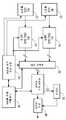
상술한 바와 같은 촬상 장치에 있어서, 각 촬상부가 노광을 개시하는 타이밍을 동기시킬 필요가 있다. 예를 들어, 특허문헌 1에 개시된 촬상 장치는, 도 10에 도시하는 바와 같이, 센서 구동 신호 발생부(34)에 의해 센서 구동 신호를 발생하여 제1 CCD 촬상부(12), 제2 CCD 촬상부(22)에 출력하고, 그 2개의 촬상부에 의한 노광을 동시에 개시시킨다. 또한, 도 10은, 특허문헌 1에 있어서의 도 1에 대하여 부호를 변경한 것이다.In the imaging device as described above, it is necessary to synchronize the timing at which each imaging unit starts exposure. For example, as shown in FIG. 10, the imaging device disclosed in
또한, 특허문헌 2에 개시된 촬상 장치도, 한쪽의 촬상부에 공급되어 있는 노광 개시 타이밍 신호를 다른 쪽의 촬상부에도 공급함으로써, 양쪽의 촬상부의 노광 개시 타이밍을 동기시키고 있다.Moreover, the imaging device disclosed in
이하의 설명에 있어서, 상술한 센서 구동 신호나 노광 개시 타이밍 신호 등, 촬상부에 노광을 개시시키는 제어 신호를 노광 개시 신호라고 한다.In the following description, a control signal for starting exposure in the imaging unit, such as the above-described sensor drive signal or exposure start timing signal, is referred to as an exposure start signal.
촬상 장치에 구비되는 복수의 촬상부가 노광 개시 신호를 수신하고 나서 노광을 개시할 때까지의 시간이 동일하면, 각 촬상부에 동일한 노광 개시 신호를 공급함으로써, 이들의 촬상부는 동시에 노광을 개시할 수 있다.If a plurality of imaging units provided in the imaging apparatus receive the exposure start signal and then the time from the exposure start is the same, by supplying the same exposure start signal to each imaging unit, these imaging units can start exposure at the same time. have.
그러나, 1개의 촬상 장치에 포함되는 복수의 촬상부는, 반드시 동일한 것이라고는 할 수 없다. 예를 들어, 코스트 다운을 위해, 한쪽의 촬상부로서는 기능이 높은 것을 사용하고, 다른 쪽의 촬상부로서는 기능이 낮은 것을 사용하는 경우가 있다. 또한, 1개의 촬상 장치에 사용되는 복수의 촬상부에 각각 해당하는 칩으로서는, 메이커가 다른 것을 사용하는 경우도 있다.However, the some imaging part contained in one imaging device is not necessarily the same thing. For example, for cost down, one of the imaging units may use a high function, and the other imaging unit may use a low function. Moreover, as a chip | tip corresponding to the some imaging part used for one imaging device, respectively, a different manufacturer may be used.
이들의 경우에서, 각각의 촬상부가 노광 개시 신호를 수신하고 나서 노광을 개시할 때까지의 시간은, 촬상부마다 서로 다를 가능성이 높다. 그 때문에, 복수의 촬상부에 동일한 노광 개시 신호를 공급해도, 각각의 촬상부에 의한 노광의 개시 시간에 어긋남이 생겨 버릴 우려가 있다.In these cases, there is a high possibility that the time from the respective imaging section to the exposure start signal after receiving the exposure start signal is different for each imaging section. Therefore, even if the same exposure start signal is supplied to a plurality of imaging units, there is a possibility that a deviation occurs in the start time of exposure by each imaging unit.
본 발명의 하나의 양태는, 촬상 장치이다. 그 촬상 장치는, 제1 촬상부, 제2 촬상부, 제1 제어부를 구비한다.One aspect of the present invention is an imaging device. The imaging device includes a first imaging unit, a second imaging unit, and a first control unit.
제1 촬상부는, 노광과, 그 노광에 의해 얻어진 화상 신호의 출력을 반복함으로써 제1 영상 신호를 얻어 출력한다.The first imaging unit obtains and outputs the first video signal by repeating the exposure and the output of the image signal obtained by the exposure.
제2 촬상부는, 노광과, 그 노광에 의해 얻어진 화상 신호의 출력을 반복함으로써 제2 영상 신호를 얻는다.The second imaging unit obtains the second video signal by repeating the exposure and the output of the image signal obtained by the exposure.
제1 제어부는, 제1 촬상부 또는 제2 촬상부가 노광을 개시하는 타이밍을 제어한다. 구체적으로는, 제2 촬상부가 노광을 개시하는 타이밍을 제어하는 경우에, 그 제1 제어부는, 제1 촬상부의 노광 출력 시간으로부터 제1 차분을 감산하여 제2 차분을 얻고, 노광 레이트로부터 그 제2 차분을 감산하여 얻은 값의 분만큼 노광을 개시하는 타이밍을 제2 촬상부에 지연시키는 제1 제어 신호를 출력한다. 또한, 제1 촬상부가 노광을 개시하는 타이밍을 제어하는 경우에, 제1 제어부는, 상기 제2 차분의 분만큼 노광을 개시하는 타이밍을 제1 촬상부에 지연시키는 제1 제어 신호를 출력한다.The first control unit controls the timing at which the first imaging unit or the second imaging unit starts exposure. Specifically, in the case where the second imaging unit controls the timing of starting exposure, the first control unit subtracts the first difference from the exposure output time of the first imaging unit to obtain the second difference, and the first from the exposure rate. The first control signal for delaying the timing of starting exposure by the second obtained by subtracting the second difference is output to the second imaging unit. In addition, when the 1st imaging part controls the timing which starts exposure, a 1st control part outputs the 1st control signal which delays the timing which starts exposure by the said 2nd difference part to a 1st imaging part.
노광 출력 시간은, 상기 촬상부가, 노광을 개시하고 나서, 그 노광에 의해 얻어진 화상 신호의 출력을 개시할 때까지의 시간차이다.The exposure output time is a time difference from when the imaging unit starts exposure and starts output of the image signal obtained by the exposure.
제1 차분은, 제1 촬상부가 소정의 화상 신호의 출력을 개시한 타이밍과, 제2 촬상부가, 제1 촬상부에 의해 상기 소정의 화상 신호의 출력을 개시한 직후에 출력한 화상 신호를 얻기 위한 노광을 개시한 타이밍과의 차분이다.The first difference is obtained by timing at which the first imaging unit starts outputting the predetermined image signal, and obtaining the image signal output immediately after the second imaging unit starts outputting the predetermined image signal by the first imaging unit. This is a difference from the timing at which the exposure was started.
또한, 상기 양태의 장치를 방법이나 시스템 등으로 치환하여 표현한 것도, 본 발명의 형태로서는 유효하다.In addition, it is effective as an aspect of this invention that the apparatus of the said aspect was substituted and represented by the method, the system, etc.
본 발명에 관한 기술에 따르면, 촬상 장치에 구비된 복수의 촬상부 기능의 변동이 있어도, 노광 개시의 타이밍을 동기시킬 수 있다.According to the technique concerning this invention, even if there exists the fluctuation | variation of the some imaging part function with which the imaging device was equipped, the timing of exposure start can be synchronized.
도 1은 본 발명의 제1 실시 형태에 관한 촬상 장치를 도시하는 도면이다.
도 2는 도 1에 도시하는 촬상 장치에서의 제1 제어부에 의한 제어가 이루어지지 않는 경우의, 각 신호의 타이밍의 예를 나타내는 도면이다.
도 3은 도 1에 도시하는 촬상 장치에서의 제1 제어부에 의한 제어가 이루어지는 경우의, 각 신호의 타이밍의 예를 나타내는 도면이다.
도 4는 본 발명의 제2 실시 형태에 관한 촬상 장치를 도시하는 도면이다.
도 5는 도 4에 도시하는 촬상 장치에서의 각 신호의 타이밍의 예를 나타내는 도면이다.
도 6은 본 발명의 제3 실시 형태에 관한 촬상 장치를 도시하는 도면이다.
도 7은 도 6에 도시하는 촬상 장치에서의 제2 촬상부의 제1 제어부와 제2 제어부 중 어느 것에 의한 제어도 이루어지지 않는 경우의, 각 신호의 타이밍의 예를 나타내는 도면이다.
도 8은 도 6에 도시하는 촬상 장치에서의 제2 촬상부의 제1 제어부에 의한 제어가 이루어지고, 제2 제어부에 의한 제어가 이루어지지 않는 경우의, 각 신호의 타이밍의 예를 나타내는 도면이다.
도 9는 도 6에 도시하는 촬상 장치에서의 제2 촬상부의 제1 제어부와 제2 제어부 중 어느 것에 의한 제어도 이루어지는 경우의, 각 신호의 타이밍의 예를 나타내는 도면이다.
도 10은 종래 기술의 예를 나타내는 도면이다.1 is a diagram showing an imaging device according to a first embodiment of the present invention.
FIG. 2 is a diagram illustrating an example of the timing of each signal when the control by the first control unit in the imaging device shown in FIG. 1 is not performed.
3 is a diagram illustrating an example of timing of each signal in the case where control by the first control unit in the imaging device shown in FIG. 1 is performed.
4 is a diagram showing an imaging device according to a second embodiment of the present invention.
5 is a diagram illustrating an example of the timing of each signal in the imaging device shown in FIG. 4.
6 is a diagram showing an image pickup device according to a third embodiment of the present invention.
FIG. 7 is a diagram illustrating an example of timing of each signal in a case where control by either the first control unit or the second control unit of the second imaging unit in the imaging device shown in FIG. 6 is not performed.
FIG. 8 is a diagram illustrating an example of timing of each signal in the case where control by the first control unit of the second imaging unit in the imaging device shown in FIG. 6 is performed and control by the second control unit is not performed.
FIG. 9 is a diagram illustrating an example of timing of each signal when control is performed by either the first control unit or the second control unit of the second imaging unit in the imaging device shown in FIG. 6.
10 is a diagram illustrating an example of the prior art.
이하, 도면을 참조하여 본 발명의 실시 형태에 대해서 설명한다. 설명의 명확화를 위해, 이하의 기재 및 도면은, 적절하게, 생략 및 간략화가 이루어져 있다. 또한, 각 도면에 있어서, 동일한 요소에는 동일한 부호가 부여되어 있고, 필요에 따라서 중복 설명은 생략되어 있다.Hereinafter, embodiments of the present invention will be described with reference to the drawings. For clarity of explanation, the following descriptions and drawings are omitted and simplified as appropriate. In addition, in each figure, the same code | symbol is attached | subjected to the same element, and duplication description is abbreviate | omitted as needed.
<제1 실시 형태>≪ First Embodiment >
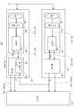
도 1은, 본 발명의 제1 실시 형태에 관한 촬상 장치(100)를 도시한다. 촬상 장치(100)는, 제1 촬상부(110), 제2 촬상부(150), 표시부(190)를 갖는다. 제1 촬상부(110)와 제2 촬상부(150)에는, 동일한 노광 개시 신호(ST)가 입력된다. 또한, 이 노광 개시 신호(ST)는, 예를 들어, 촬상 장치(100)에 구비된 촬상 개시 버튼(도시하지 않음)을 밑으로 누름으로써 출력된다.1 shows an
제1 촬상부(110)는, 노광 개시 신호(ST)를 수신하면 촬상을 개시하고, 촬상에 의해 제1 영상 신호(VA)를 얻어 표시부(190)에 출력한다.When the
제2 촬상부(150)는, 노광 개시 신호(ST)를 수신하면 촬상을 개시하고, 촬상에 의해 제2 영상 신호(VB)를 얻어 표시부(190)에 출력한다.When the
표시부(190)는, 제1 촬상부(110)로부터 출력된 제1 영상 신호(VA)와, 제2 촬상부(150)로부터 출력된 제2 영상 신호(VB)를 사용해서 입체 영상을 생성하여 표시한다.The
제1 촬상부(110)와 제2 촬상부(150)를 상세하게 설명한다.The
제1 촬상부(110)는, 이미지 센서 모듈(120)과 해석부(130)를 갖고, 노광 개시 신호(ST)에 따라서 1회째의 노광을 개시하는 동시에, 그 1회째의 노광에 의해 얻어진 화상 신호 A21을 출력한다. 그 후, 노광과, 그 노광에 의해 얻어진 화상 신호의 출력을 반복한다. 이에 의해, 제1 촬상부(110)로부터, 제1 영상 신호(VA)를 구성하는 각 화상 신호(A21, A22, …)는, 표시부(190)에 순차 출력된다.The
제1 촬상부(110)가 노광을 개시하고 나서, 그 노광에 의해 얻어지는 화상 신호(A21, A22 등)를 출력할 때까지의 시간을, 「노광 출력 시간」이라고 한다. 이 「노광 출력 시간」은, 촬상부 내부에서 행하는 처리 등의 스펙에 따라서 다르므로, 촬상부마다 다를 가능성이 있다. 이하, 제1 촬상부(110)의 노광 출력 시간을 「ΔA」로 표기한다.The time from when the
이미지 센서 모듈(120)은, 통상의 이러한 종류의 이미지 센서 모듈과 마찬가지의 것이며, 렌즈(122), 촬상 소자(124), 조정부(126)를 구비한다. 노광 개시 후, 촬상 소자(124)는 렌즈(122)로부터의 광 신호를 소정의 샘플링 레이트(노광 레이트)로 광전 변환하여 복수의 화상 신호(A11, A12, …)를 순차 얻어 조정부(126)에 출력한다.The
조정부(126)는, 촬상 소자(124)로부터의 화상 신호(A11, A12, …)에 대하여 게인 조정 등을 행하여 화상 신호(A21, A22, …)를 얻어 해석부(130)에 출력한다.The adjusting
해석부(130)는, 이미지 센서 모듈(120)로부터의 화상 신호(A21, A22, …)에 대하여 화상 처리를 행함으로써 해석을 행하고, 해석 결과에 따른 노출 정보(FA)를 이미지 센서 모듈(120)에 피드백하는 동시에, 동기 신호(SA)와 함께 화상 신호(A21, A22, …)를 표시부(190)에 순차 출력한다.The
또한, 해석부(130)로부터 이미지 센서 모듈(120)에 피드백되는 노출 정보(FA)는, 셔터 스피드나 게인 등의 정보를 포함하고, 예를 들어 최적의 밝기로 촬상할 수 있도록 노출 제어를 행하기 위해 사용된다. 해석부(130)의 이 기능은, 「Auto Exposure」라고 불리고, 통상의 이러한 종류의 촬상부에 구비된다.The exposure information FA fed back from the
제2 촬상부(150)는, 이미지 센서 모듈(160)과 해석부(170)를 갖고, 이미지 센서 모듈(160)은, 렌즈(162), 촬상 소자(164), 조정부(166)를 구비한다.The
제2 촬상부(150)는, 해석부(170)가 제1 촬상부(110)의 해석부(130)와 서로 다른 점과, 제1 촬상부(110)가 제1 영상 신호(VA)를 출력할 때의 동기 신호(SA)가 입력되는 점을 제외하고, 각 기능 블록은, 제1 촬상부(110)에 서로 대응하는 기능 블록과 마찬가지의 동작을 한다. 즉, 제2 촬상부(150)는, 노광 개시 신호(ST)에 따라서 1회째의 노광을 개시하는 동시에, 그 1회째의 노광에 의해 얻어진 화상 신호(B21)를 출력한다. 그 후, 노광과, 그 노광에 의해 얻어진 화상 신호의 출력을 반복한다. 이에 의해, 제2 촬상부(150)로부터, 제2 영상 신호(VB)를 구성하는 각 화상 신호(B21, B22, …)는, 표시부(190)에 순차 출력된다. 화상 신호 B21, B22, … 등이 출력될 때의 동기 신호는, SB이다.In the
또한, 제1 촬상부(110)와 제2 촬상부(150)의 노광 레이트(샘플링 레이트)는 동일하고, 제1 영상 신호(VA)와 제2 영상 신호(VB)의 프레임 레이트도 동일하다. 또한, 본 실시 형태에 있어서, 제2 촬상부(150)의 노광 출력 시간(이하 ΔB로 표기함)은, 제1 촬상부(110)의 노광 출력 시간(ΔA)과 마찬가지인 것으로 한다.In addition, the exposure rates (sampling rate) of the
해석부(170)는, 제1 제어부(172)를 구비한다. 제1 제어부(172)의 기능을 제외하면, 해석부(170)는, 통상의 이러한 종류의 촬상부와 마찬가지의 동작을 한다. 즉, 이미지 센서 모듈(160)로부터의 화상 신호(B21, B22, …)에 대하여 화상 처리를 함으로써 해석을 행하고, 노출 정보(FB)를 이미지 센서 모듈(160)에 피드백하는 동시에, 동기 신호(SB)에 따라서 화상 신호(B21, B22, …)를 표시부(190)에 순차 출력한다. 해석부(170)로부터 이미지 센서 모듈(160)에 피드백되는 노출 정보(FB)는, 노출 정보(FA)와 마찬가지로, 「Auto Exposure」를 위한 셔터 스피드나 게인 등의, 최적의 밝기로 촬상할 수 있도록 노출 제어를 행하기 위한 것이다.The
본 실시 형태에 있어서, 해석부(170)는, 또한, 후술하는 제1 제어 신호(CTR1)에 따라서, 노광 개시의 타이밍의 지연량을 나타내는 정보를 노출 정보(FB)에 포함시켜 이미지 센서 모듈(160)에 출력하도록 되어 있다. 또한, 제1 제어 신호(CTR1)가 나타내는 값이 「0」인 경우에는, 해석부(170)는, 통상의 이러한 종류의 촬상부에 구비되는 해석부와 마찬가지의 동작을 한다.In the present embodiment, the
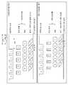
제1 제어부(172)에 대해서 상세하게 설명한다. 우선, 도 2를 참조하여, 이하의 설명에서 사용하는 제1 차분(Δt1), 제2 차분(Δt2)을 설명한다. 또한, 도 2는, 제1 제어부(172)에 의한 제어가 이루어져 있지 않은 경우의 예이다.The
도 2의 상부는, 제1 촬상부(110)에 있어서, 노광 개시 신호(ST)와, 이미지 센서 모듈(120)에 의한 노광과, 해석부(130)에 의한 화상 신호[화상 신호(A21, A22, …)]의 취득 및 해석을 위한 화상 처리와, 동기 신호(SA)의 타이밍 관계의 예를 나타낸다. 노광 개시 신호(ST) 아래의 각 평행 사변형은, 각각 1회의 노광을 나타내고, 좌측상단의 정점이 그 노광의 개시 타이밍을 나타내고, 우측하단의 정점이 그 노광의 완료 타이밍을 나타낸다. 육각형은 해석부(130)에 의한 1회의 취득을 나타내고, 좌측단부의 정점이 그 취득의 개시 타이밍을 나타내고, 우측단부의 정점이 그 취득의 완료 타이밍을 나타낸다. 또한, 직사각형은, 해석부(130)에 의한 1회의 화상 처리를 나타내고, 좌측변이 그 화상 처리의 개시 타이밍을 나타내고, 우측변이 그 화상 처리의 완료 타이밍을 나타낸다. 또한, 도면 중의 숫자는, 시계열의 순번을 나타낸다. 예를 들어, 1회째의 노광에 의해 얻어진 화상 신호는, 1회째의 취득에 의해 해석부(130)에 취득되고, 1회째의 화상 처리가 실시되어, 동기 신호(SA)에 있어서의 「1」이 나타내는 펄스에 동기하여 출력된다.In the upper part of FIG. 2, in the
또한, 제1 촬상부(110)에 의한 연속한 2회의 노광간의 간격(이하 노광 간격이라고 함)을 「T」로 표기한다.In addition, the space | interval (hereinafter called exposure interval) between two consecutive exposures by the
도 2의 하부는, 제2 촬상부(150)에 있어서, 노광 개시 신호(ST)와, 이미지 센서 모듈(160)에 의한 노광과, 해석부(170)에 의한 화상 신호[화상 신호(B21, B22, …)]의 취득 및 해석을 위한 화상 처리와, 동기 신호(SB)의 타이밍 관계의 예를 나타낸다. 평행 사변형, 육각형, 직사각형 등의 도형이나, 숫자의 의미는, 전술한 바와 같다. 또한, 제1 촬상부(110)와 제2 촬상부(150)의 노광 레이트가 동일하므로, 제2 촬상부(150)의 노광 간격도 「T」이다.In the lower part of FIG. 2, in the
본 명세서에서 말하는 제1 차분(Δt1)은, 제1 촬상부(110)가 소정의 화상 신호의 출력을 개시한 타이밍과, 제2 촬상부(150)가, 제1 촬상부(110)에 의해 상기 소정의 화상 신호의 출력을 개시한 직후에 출력한 화상 신호를 얻기 위한 노광을 개시한 타이밍과의 차분을 의미한다.In the first difference Δt1 described herein, the timing at which the
본 실시 형태에 있어서, 상기 「소정의 화상 신호」로서, 첫번째의 화상 신호가 사용된다. 즉, 본 실시 형태에 있어서, 제1 차분(Δt1)은, 제1 촬상부(110)가 첫번째의 화상 신호의 출력을 개시한 타이밍과, 제2 촬상부(150)가, 제1 촬상부(110)에 의한 첫번째의 화상 신호의 출력을 개시한 직후에 출력한 화상 신호를 얻기 위한 노광을 개시한 타이밍과의 차분이 된다.In this embodiment, the first image signal is used as the "predetermined image signal". That is, in the present embodiment, the first difference Δt1 is a timing at which the
도 2에 도시하는 예의 경우에서, 제1 촬상부(110)가 첫번째의 화상 신호[(화상 신호(A21)]의 출력을 개시한 직후에 제2 촬상부(150)가 출력을 개시한 화상 신호도 첫번째의 화상 신호[(화상 신호(B21)]이므로, 제1 차분(Δt1)은, 화상 신호(A21)의 출력 개시 타이밍과, 화상 신호(B21)를 얻기 위한 노광이 개시된 타이밍과의 차분이 된다.In the case of the example shown in FIG. 2, an image signal in which the
전술한 바와 같이, 본 실시 형태에 있어서, 동기 신호(SA)는, 제2 촬상부(150)에도 입력된다. 제2 촬상부(150)에 있어서, 해석부(170)에 있어서의 제1 제어부(172)는, 이 동기 신호(SA)에 기초하여, 제1 촬상부(110)에 의한 첫번째의 화상 신호[화상 신호(A21)]의 출력 개시 타이밍을 취득하고, 제2 촬상부(150)에 의한 첫번째의 화상 신호[화상 신호(B21)]를 취득하기 위한 노광이 개시된 타이밍과의 차분을 산출하여 제1 차분(Δt1)을 얻는다.As described above, in the present embodiment, the synchronization signal SA is also input to the
그리고, 제1 제어부(172)는, 제1 촬상부(110)의 노광 출력 시간(ΔA)으로부터 제1 차분(Δt1)을 감산하여 제2 차분(Δt2)을 얻고, 또한, 노광 간격(T)으로부터 제2 차분(Δt2)을 감산하여 값 「T-Δt2」를 얻는다. 이 값 「T-Δt2」는, 제2 촬상부(150)에 의한 다음 노광의 개시 타이밍이 지연되어야 하는 만큼을 나타내는 제1 제어 신호(CTR1)가 된다. 또한, 본 실시 형태에 있어서, 제1 제어부(172)는, 제1 촬상부(110)의 노광 출력 시간(ΔA)의 값을 미리 유지하고 있다.The
제1 촬상부(110)에 있어서의 해석부(130)는, 제1 제어 신호(CTR1)가 나타내는 지연량(「T-Δt2」)을 노출 정보(FB) 내에 포함시켜, 이미지 센서 모듈(160)에 피드백한다.The
또한, 제1 제어부(172)가 값 「T-Δt2」를 나타내는 제1 제어 신호(CTR1)를 얻었을 때에, 이미지 센서 모듈(160)이 이미 2회째의 노광을 개시하였기 때문에, 이미지 센서 모듈(160)에 의한 3회째의 노광이 지연되게 된다.In addition, when the
이에 의해, 도 2에 대응하는 타이밍차트는, 도 3에 도시하게 된다. 이미지 센서 모듈(160)에 의한 3회째의 노광의 개시가 「T-Δ2」만큼 지연되게 되므로, 제2 촬상부(150)에 의한 3회째 이후의 각 회의 노광(3회째, 4회째, …)의 개시 타이밍은, 제1 촬상부(110)에 의한 4회째 이후의 각 회의 노광(4회째, 5회째, …)의 개시 타이밍과 각각 동일해진다.As a result, the timing chart corresponding to FIG. 2 is shown in FIG. 3. Since the start of the third exposure by the
전술한 바와 같이, 본 실시 형태에 있어서, 제1 촬상부(110)의 노광 출력 시간(ΔA)과, 제2 촬상부(150)의 노광 출력 시간(ΔB)이 동일하다. 따라서, 제1 촬상부(110)의 4회째의 노광과, 제2 촬상부(150)의 3회째의 노광의 개시 타이밍이 동일해지면, 제1 촬상부(110)에 의해 얻어지는 4매째의 화상 신호와, 제2 촬상부(150)에 의해 얻어지는 3매째의 화상 신호는, 동일한 타이밍으로 출력된다. 이후의 각 회의 노광에 의해 얻어지는 화상 신호도 마찬가지이다.As described above, in the present embodiment, the exposure output time ΔA of the
이와 같이, 본 실시 형태의 촬상 장치(100)에 따르면, 2개의 촬상부의 노광 개시 타이밍을 동기시킬 수 있다.Thus, according to the
또한, 상기 2개의 촬상부의 노광 출력 시간이 동일하면, 그 2개의 촬상부로부터 화상 신호를 출력하는 타이밍도 동기하게 된다.If the exposure output times of the two imaging units are the same, the timing of outputting image signals from the two imaging units is also synchronized.
<제2 실시 형태>≪ Second Embodiment >
제1 실시 형태의 촬상 장치(100)에 있어서, 제2 촬상부(150)에 의한 노광의 개시 타이밍을 「T-Δt2」만큼 지연시킴으로써 제1 촬상부(110)와 제2 촬상부(150)의 노광 개시 타이밍을 동기시키고 있지만, 제1 촬상부(110)에 의한 노광의 개시 타이밍을 지연시킴으로써 제1 촬상부(110)와 제2 촬상부(150)의 노광 개시 타이밍을 동기시키도록 해도 좋다. 이에 대해서, 도 4에 도시하는 제2 실시 형태에 관한 촬상 장치(200)를 이용하여 설명한다.In the
도 4에 도시하는 촬상 장치(200)는, 제1 촬상부(110)와 제2 촬상부(150)에 구비되는 해석부(132)와 해석부(174)가, 도 1에 도시하는 해석부(130)와 해석부(170)와 각각 서로 다른 점을 제외하고, 도 1에 도시하는 촬상 장치(100)와 마찬가지이다.In the
본 실시 형태에 있어서, 해석부(132)에는, 제2 촬상부(150), 구체적으로는 해석부(170)에서의 해석부(174)로부터 제1 제어 신호(CTR1)가 입력되도록 되어 있고, 해석부(132)는, 이 제1 제어 신호(CTR1)에 따라서, 노광 개시의 타이밍의 지연량을 나타내는 정보를 노출 정보(FA)에 포함시켜 이미지 센서 모듈(120)에 출력하도록 되어 있다. 또한, 제1 제어 신호(CTR1)가 나타내는 값이 「0」인 경우에는, 해석부(132)는, 통상의 이러한 종류의 촬상부에 구비되는 해석부와 마찬가지의 동작을 한다.In the present embodiment, the first control signal CTR1 is input to the
제2 촬상부(150)의 해석부(174)에서의 제1 제어부(176)는, 제1 제어 신호(CTR1)를 제1 촬상부(110)의 해석부(132)에 출력한다. 이 제1 제어 신호(CTR1)는, 제1 촬상부(110)에서의 제1 제어 신호(CTR1)와 서로 다르다. 또한, 해석부(174)가 이미지 센서 모듈(160)에 피드백하는 노출 정보(FB)에는, 제1 제어 신호(CTR1)에 관한 정보가 포함되지 않는다.The
여기서, 해석부(174)의 제1 제어부(176)가 출력하는 제1 제어 신호(CTR1)를 설명한다. 또한, 제1 제어부(176)에 의한 제어가 이루어지지 않는 경우의 각 신호의 타이밍은, 도 2에 도시하는 예와 마찬가지인 것으로 한다.Here, the 1st control signal CTR1 output by the
본 실시 형태에 있어서, 제1 제어부(176)는, 제1 촬상부(110)의 노광 출력 시간(ΔA)의 값을 미리 유지하고 있고, 노광 출력 시간(ΔA)으로부터 상술한 제1 차분(Δt1)을 감산하여 제2 차분(Δt2)을 얻는다. 그리고, 이 제2 차분(Δt2)을 제1 제어 신호(CTR1)로서 제1 촬상부(110)의 해석부(132)에 출력한다.In this embodiment, the
제1 촬상부(110)에서의 해석부(130)는, 제1 제어 신호(CTR1)가 나타내는 지연량[여기서는 제2 차분(Δt2)]을 노출 정보(FA) 내에 포함시켜, 이미지 센서 모듈(120)에 피드백한다.The
또한, 제1 제어부(176)가 제2 차분(Δt2)을 나타내는 제1 제어 신호(CTR1)를 얻었을 때에, 제1 촬상부(110)가 이미 2회째의 노광을 개시하였으므로, 제1 촬상부(110)에 의한 3회째의 노광이 지연되게 된다.In addition, when the
이에 의해, 도 2에 대응하는 타이밍차트는, 도 5에 도시하게 된다. 이미지 센서 모듈(120)에 의한 3회째의 노광의 개시가 제2 차분(Δt2)만큼 지연되게 되므로, 제1 촬상부(110)에 의한 3회째 이후의 각 회의 노광(3회째, 4회째, …)의 개시 타이밍은, 제2 촬상부(150)에 의한 3회째 이후의 각 회의 노광(3회째, 4회째, …)의 개시 타이밍과 각각 동일해진다.As a result, the timing chart corresponding to FIG. 2 is shown in FIG. 5. Since the start of the third exposure by the
제1 촬상부(110)의 노광 출력 시간(ΔA)과, 제2 촬상부(150)의 노광 출력 시간(ΔB)이 동일하므로, 제1 촬상부(110)와 제2 촬상부(150)의 3회째 이후의 각 회의 노광의 개시 타이밍이 동일해지면, 제1 촬상부(110)와 제2 촬상부(150)로부터, 3회째 이후에 있어서, 각 회의 화상 신호가, 동일한 타이밍으로 출력된다.Since the exposure output time ΔA of the
이와 같이, 본 실시 형태의 촬상 장치(200)에 따르면, 제1 실시 형태에 관한 촬상 장치(100)와 마찬가지의 효과를 얻을 수 있다.Thus, according to the
<제3 실시 형태>≪ Third Embodiment >
2개의 촬상부에 의해 촬상을 행하고, 정확한 입체 영상을 얻기 위해서는, 그 2개의 촬상부의 각 회의 노광 개시 타이밍을 동기시키는 것 외에, 그 2개의 촬상부의 각 회의 화상 신호의 출력 타이밍도 동기시키는 것이 필요하다.In order to capture an image by two imaging units and obtain an accurate stereoscopic image, it is necessary to synchronize the exposure start timing of each meeting of the two imaging sections, and to synchronize the output timing of each meeting image signal of the two imaging sections. Do.
상술한 촬상 장치(100)와 촬상 장치(200)는, 2개의 촬상부[제1 촬상부(110)와 제2 촬상부(150)]의 노광 출력 시간(ΔA, ΔB)이 동일한 경우에는, 그 2개의 촬상부의 노광 개시 타이밍을 동기시킬 수 있는 동시에, 화상 신호의 출력 타이밍을 동기시킬 수 있지만, 2개의 촬상부의 노광 출력 시간이 서로 다르면, 단순히 그 2개의 촬상부의 노광 개시 타이밍을 동기시키는 것만으로는, 정확한 입체 영상을 얻을 수 없다.When the
그에 반해, 도 6에 도시하는 촬상 장치(300)는, 2개의 촬상부[제1 촬상부(110)와 제2 촬상부(250)]의 노광 출력 시간이 서로 다른 경우에도, 그 2개의 촬상부의 노광 개시 타이밍을 동기시킬 수 있는 동시에, 화상 신호의 출력 타이밍을 동기시킬 수 있다. 구체적으로는, 제1 촬상부(110)의 노광 출력 시간(ΔA)이 제2 촬상부(250)의 노광 출력 시간(ΔB)보다 짧은 경우를 예로 설명한다.In contrast, the
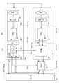
도 6에 도시하는 바와 같이, 본 발명의 제3 실시 형태에 관한 촬상 장치(300)는, 제1 촬상부(110), 제2 촬상부(250), 지연부(280), 표시부(190)를 구비한다.As shown in FIG. 6, the
촬상 장치(300)는, 제1 촬상부(110)와 표시부(190) 사이에 지연부(280)를 구비하는 점과, 제1 촬상부(110)의 노광 출력 시간(ΔA)이 제2 촬상부(250)의 노광 출력 시간(ΔB)보다 짧은 점과, 해석부(270)가 제2 제어부(274)를 더 구비한 점을 제외하고, 제2 실시 형태에 관한 촬상 장치(200)와 마찬가지이다.The
여기서, 지연부(280)와, 제2 촬상부(250)에서의 해석부(270)에 구비된 제2 제어부(274)에 대해서 설명한다. 다른 각 기능 블록은, 촬상 장치(200)에 서로 대응하는 기능 블록과 마찬가지이므로, 설명을 생략한다.Here, the
지연부(280)는, 제1 촬상부(110)로부터의 화상 신호와 동기 신호를, 제2 촬상부(250)로부터의 제2 제어 신호(CTR2)가 나타내는 지연량만큼 지연시킨다. 그로 인해, 제2 제어 신호(CTR2)가 나타내는 지연량이 「0」인 경우에는, 제1 촬상부(110)가 출력하는 화상 신호와 동기 신호는, 지연부(280)가 표시부(190)에 출력하는 화상 신호와 동기 신호와 마찬가지이다.The
제2 제어부(274)를 설명하기 전에, 우선, 도 7을 참조하여, 제1 제어부(176)에 의한 제1 촬상부(110)의 노광 개시 타이밍의 제어와, 제2 제어부(274)에 의한 지연부(280)의 제어 모두 이루어져 있지 않은 경우에서의, 각 신호의 타이밍을 설명한다. 이 경우, 제1 제어 신호(CTR1)와 제2 제어 신호(CTR2)가 나타내는 값이 항상 「0」이다.Before explaining the
도 7은, 제1과 제2 실시 형태를 설명할 때의 도 2에 대응한다. 도 7에 도시하는 바와 같이, 이 경우, 제1 촬상부(110)와 제2 촬상부(250)의 노광 개시 타이밍이 동기하지 않고, 지연부(280)와 제2 촬상부(250)가 표시부(190)에 화상 신호를 출력하는 타이밍도 동기하지 않는다. 또한, 제2 촬상부(250)의 노광 출력 시간(ΔB)이 제1 촬상부(110)의 노광 출력 시간(ΔA)보다 길다.FIG. 7 corresponds to FIG. 2 when describing the first and second embodiments. As shown in FIG. 7, in this case, the exposure start timings of the
도 8은, 제2 실시 형태를 설명할 때의 도 5에 대응하고, 제1 제어부(176)에 의한 제1 촬상부(110)의 노광 개시 타이밍의 제어가 이루어지고, 제2 제어부(274)에 의한 지연부(280)의 제어가 이루어져 있지 않은[제2 제어 신호(CTR2)가 항상 「0」임] 경우에서의, 각 신호의 타이밍을 나타내는 도면이다.FIG. 8 corresponds to FIG. 5 when describing the second embodiment, and the exposure start timing of the
이 경우, 제1 제어부(176)가 출력한, 제2 차분(Δt2)을 나타내는 제1 제어 신호(CTR1)에 의해, 제1 촬상부(110)에 의한 3회째 이후의 각 회의 노광(3회째, 4회째, …)의 개시 타이밍은, 제2 촬상부(150)에 의한 3회째 이후의 각 회의 노광(3회째, 4회째, …)의 개시 타이밍과 각각 동일하게 되어 있다.In this case, the first control signal CTR1 indicating the second difference Δt2 output by the
그러나, 제1 촬상부(110)의 노광 출력 시간(ΔA)이 제2 촬상부(250)의 노광 출력 시간(ΔB)보다 짧으므로, 제1 촬상부(110)와 제2 촬상부(250)의 각 회의 노광의 개시 타이밍이 동일하게 되어도, 제1 촬상부(110)가 노광을 하여, 지연부(280)를 통해서 표시부(190)에 출력한 화상 신호의 출력 타이밍과, 제2 촬상부(250)가 동일한 타이밍에서 노광을 개시하여 얻은 화상 신호를 표시부(190)에 출력한 화상 신호의 출력 타이밍보다 이전에 이루어져 있다. 이 출력 타이밍의 차분은, 도 8에 있어서 제3 차분(Δt3)으로서 나타내어져 있다.However, since the exposure output time ΔA of the
촬상 장치(300)에서의 해석부(270)의 제2 제어부(274)는, 제1 제어부(176)에 의한 노광 개시 타이밍의 조정이 행해진 후에, 상기 제3 차분(Δt3)을 산출한다. 구체적으로는, 동기 신호(SA)로부터, 제1 촬상부(110)로부터 출력된 소정의 화상 신호의 출력 개시 타이밍과, 그 소정의 화상 신호의 출력 개시 직후에 제2 촬상부(250)가 출력을 개시한 화상 신호의 출력 개시 타이밍과의 차분을 산출한다. 그리고, 이 차분 즉 제3 차분(Δt3)만큼의 지연량을 나타내는 제2 제어 신호(CTR2)를 지연부(280)에 출력한다.The
제2 제어부(274)가 제3 차분(Δt3)을 산출할 때에, 그 출력 타이밍이 사용되는 상기 「소정의 화상 신호」로서는, 제1 제어부(176)에 의한 노광 개시 타이밍의 조정이 행해진 후에 제1 촬상부(110)가 노광을 하여 얻은 어떠한 화상 신호이어도 좋지만, 출력 타이밍을 빨리 동기시키기 위해, 빠른 시간의 노광에 의해 얻어진 화상 신호인 것이 바람직하다.When the
도 8에 도시하는 예의 경우, 제1 제어부(176)에 의한 제1 촬상부(110)의 노광 개시 타이밍의 조정이 이루어진 후의 제1 촬상부(110)의 가장 빠른 노광은, 제1 촬상부(110)가 노광 개시 신호(ST)를 수신한 후의 3회째의 노광이 된다. 또한, 상기 노광에 의해 얻어진 화상 신호의 출력 개시 직후에 제2 촬상부(250)가 출력을 개시한 화상 신호도, 제2 촬상부(250)에 의한 3회째의 노광에 의해 얻어진 화상 신호이다.In the example shown in FIG. 8, the earliest exposure of the
따라서, 제2 제어부(274)는, 제1 촬상부(110)의 3회째의 노광에 의해 얻어진 화상 신호의 출력 개시 타이밍과, 제2 촬상부(250)의 3회째의 노광에 의해 얻어진 화상 신호의 출력 개시 타이밍과의 차분을 제3 차분(Δt3)으로서 산출하고, 제3 차분(Δt3)을 나타내는 제2 제어 신호(CTR2)를 지연부(280)에 출력한다.Therefore, the
지연부(280)는, 제2 제어 신호(CTR2)를 수신하면, 표시부(190)에 다음에 출력하는 화상 신호(4회째의 노광에 의해 얻어지는 화상 신호)의 출력 개시 타이밍을, 제3 차분(Δt3)의 분만큼 지연시킨다. 이에 의해, 각 신호의 타이밍은, 도 9에 도시하게 된다.When the
도 9에 도시하는 바와 같이, 제1 촬상부(110)의 4회째의 노광에 의해 얻어지는 화상 신호의 표시부(190)에의 출력 개시 타이밍은, 제3 차분(Δt3)만큼 지연되게 되어 있다. 그 때문에, 상기 화상 신호로부터, 제1 촬상부(110)와 제2 촬상부(250)의 각 노광에 의해 얻어지는 화상 신호는, 동기하여 표시부(190)에 입력되게 된다.As shown in FIG. 9, the output start timing of the image signal obtained by the 4th exposure of the
이와 같이, 본 실시 형태의 촬상 장치(300)에 따르면, 제1 촬상부(110)와 제2 촬상부(250)의 노광 출력 시간이 서로 다른 경우에도, 그 2개의 촬상부의 노광 개시 타이밍을 동기시킬 수 있는 동시에, 화상 신호의 출력 타이밍을 동기시킬 수 있다.Thus, according to the
이상, 실시 형태를 기초로 본 발명을 설명하였다. 실시 형태는 예시이며, 본 발명의 주지로부터 일탈하지 않는 한, 상술한 각 실시 형태에 대하여 다양하게 변경, 증감을 행해도 좋다. 이들의 변경, 증감이 행해진 변형예도 본 발명의 범위에 있는 것은 당업자에게 이해되는 바이다.In the above, this invention was demonstrated based on embodiment. Embodiment is an illustration and you may change and change variously about each above-mentioned embodiment, unless it deviates from the well-known of this invention. It is understood by those skilled in the art that modifications of these modifications and changes are also made within the scope of the present invention.
예를 들어, 상술한 각 실시 형태로서, 2개의 촬상부를 구비한 촬상 장치를 예로 하고 있지만, 본 발명의 기술을, 2개 이상의 임의의 수의 촬상부를 구비한 촬상 장치에 적용할 수 있는 것은, 물론이다.For example, as each embodiment mentioned above, although the imaging device provided with two imaging parts is taken as an example, what can apply the technique of this invention to the imaging device provided with two or more arbitrary numbers of imaging parts, Of course.
또한, 제3 실시 형태의 촬상 장치(300)에 있어서, 노광 출력 시간이 짧은 촬상부[제1 촬상부(110)]의 외부에 지연부(280)를 설치하고 있지만, 노광 출력 시간이 짧은 촬상부의 내부에 기능 블록의 증설이 가능하면, 지연부(280)의 기능을 달성하는 기능 블록을 그 촬상부의 내부에 설치해도 좋고, 그 촬상부의 내부의 기존의 기능 블록[예를 들어 해석부(130)]에 지연부(280)의 기능을 추가하도록 해도 좋다.Moreover, in the
또한, 촬상 장치(300)에 있어서, 제1 촬상부(110)와 제2 촬상부(250)의 노광 개시 타이밍의 조정 방법으로서, 제2 실시 형태에 관한 촬상 장치(200)에 의한 방법을 사용하였지만, 제1 실시 형태에 관한 촬상 장치(100)에 의한 방법을 이용해도 좋다.Moreover, in the
또한, 상술한 각 실시 형태에 있어서, 노광 개시 타이밍의 조정과, 화상 신호의 출력 타이밍의 조정을 일회만 행하도록 되어 있지만, 복수회 행하도록 해도 좋다. 복수회를 행하는 경우는, 예를 들어, 소정의 시간 간격마다 행하도록 해도 좋다.In addition, in each embodiment mentioned above, although adjustment of exposure start timing and adjustment of the output timing of an image signal are performed only once, you may make it multiple times. When performing multiple times, you may carry out every predetermined time interval, for example.
본 출원은, 2011년 3월 8일에 출원된 일본 출원 특원 제2011-050114호를 기초로 하는 우선권을 주장하고, 그 개시된 모두를 여기에 원용한다.This application claims priority based on Japanese Patent Application No. 2011-050114 for which it applied on March 8, 2011, and uses all that the indication here.
12 : 제1 CCD 촬상부
14 : 제1 CDS/AGC/AD부
22 : 제2 CCD 촬상부
24 : 제2 CDS/AGC/AD부
34 : 센서 구동 신호 발생부
100 : 촬상 장치
110 : 제1 촬상부
120 : 이미지 센서 모듈
122 : 렌즈
124 : 촬상 소자
126 : 조정부
130 : 해석부
132 : 해석부
150 : 제2 촬상부
160 : 이미지 센서 모듈
162 : 렌즈
164 : 촬상 소자
166 : 조정부
170 : 해석부
172 : 제1 제어부
174 : 해석부
176 : 제1 제어부
190 : 표시부
200 : 촬상 장치
250 : 제2 촬상부
270 : 해석부
274 : 제2 제어부
280 : 지연부
300 : 촬상 장치
T : 노광 간격
Δt1 : 제1 차분
Δt2 : 제2 차분
Δt3 : 제3 차분
CTR1 : 제1 제어 신호
CTR2 : 제2 제어 신호12: first CCD imaging unit
14: First CDS / AGC / AD Part
22: second CCD imaging unit
24: 2nd CDS / AGC / AD Part
34: sensor drive signal generator
100: imaging device
110: first imaging unit
120: image sensor module
122: lens
124: imaging device
126: adjusting unit
130: analysis unit
132: analysis unit
150: second imaging unit
160: image sensor module
162 lens
164: imaging device
166: adjusting unit
170: analysis unit
172: first control unit
174: analysis unit
176: first control unit
190:
200: imaging device
250: second imaging unit
270: analysis unit
274: second control unit
280: delay unit
300: imaging device
T: exposure interval
Δt1: first difference
Δt2: second difference
Δt3: third difference
CTR1: first control signal
CTR2: second control signal
Claims (4)
Translated fromKorean노광과, 그 노광에 의해 얻어진 화상 신호의 출력을 반복함으로써 제2 영상 신호를 얻어 출력하는 제2 촬상부와,
상기 제1 촬상부 또는 상기 제2 촬상부가 노광을 개시하는 타이밍을 제어하는 제1 제어부
를 구비하고,
상기 제1 제어부는,
상기 제1 촬상부의 노광 출력 시간으로부터 제1 차분을 감산하여 제2 차분을 얻고,
노광 간격으로부터 상기 제2 차분을 감산하여 얻은 값의 분만큼 노광을 개시하는 타이밍을 상기 제2 촬상부에 지연시키는 제1 제어 신호, 또는, 상기 제2 차분의 분만큼 노광을 개시하는 타이밍을 상기 제1 촬상부에 지연시키는 제1 제어 신호를 출력하고,
상기 노광 출력 시간은, 해당 촬상부가, 노광을 개시하고 나서, 그 노광에 의해 얻어진 화상 신호의 출력을 개시할 때까지의 시간차이며,
상기 제1 차분은, 상기 제1 촬상부가 소정의 화상 신호의 출력을 개시한 타이밍과, 상기 제2 촬상부가, 상기 제1 촬상부에 의해 상기 소정의 화상 신호의 출력을 개시한 직후에 출력한 화상 신호를 얻기 위한 노광을 개시한 타이밍과의 차분인 것을 특징으로 하는 촬상 장치.A first imaging unit which obtains and outputs a first video signal by repeating exposure and output of an image signal obtained by the exposure;
A second imaging unit which obtains and outputs a second video signal by repeating the exposure and output of the image signal obtained by the exposure;
A first control unit controlling a timing at which the first imaging unit or the second imaging unit starts exposure;
And,
The first control unit,
Subtract the first difference from the exposure output time of the first imaging unit to obtain a second difference,
The first control signal which delays the timing of starting exposure by the value obtained by subtracting the second difference from the exposure interval by the second imaging unit, or the timing of starting exposure by the second difference, Outputting a first control signal delaying the first imaging unit,
The exposure output time is a time difference from when the image capturing unit starts exposure to when the image signal obtained by the exposure starts.
The first difference is a timing at which the first imaging unit starts outputting a predetermined image signal, and the second imaging unit outputs immediately after starting output of the predetermined image signal by the first imaging unit. It is a difference with the timing which started exposure to acquire an image signal, The imaging device characterized by the above-mentioned.
상기 제1 제어부는, 상기 제1 촬상부가 화상 신호를 동기하여 출력하기 위한 제1 동기 신호에 기초하여, 상기 제1 촬상부가, 상기 소정의 화상 신호의 출력을 개시한 타이밍을 취득하는 것을 특징으로 하는 촬상 장치.The method of claim 1,
The first control unit acquires a timing at which the first imaging unit starts outputting the predetermined image signal based on a first synchronization signal for synchronously outputting an image signal by the first imaging unit. Imaging device.
상기 제1 제어부는, 상기 제2 촬상부와 동일한 칩에 설치되어 있는 것을 특징으로 하는 촬상 장치.3. The method according to claim 1 or 2,
The first control unit is provided on the same chip as the second imaging unit.
상기 제1 촬상부와 상기 제2 촬상부 중의, 상기 노광 출력 시간이 짧은 한쪽의 촬상부가 출력한 영상 신호에 포함되는 화상 신호의 출력 타이밍을 제어하는 제2 제어부를 더 구비하고,
상기 제2 제어부는, 상기 한쪽의 촬상부가 출력한 영상 신호에 포함되는 소정의 화상 신호의 출력이 개시된 타이밍과, 다른 쪽의 촬상부가 출력한 영상 신호에 포함되는, 상기 소정의 화상 신호의 직후에 출력이 개시된 화상 신호의 상기 출력이 개시된 타이밍과의 차분인 제3 차분을 산출하고, 상기 한쪽의 촬상부가 출력한 영상 신호에 포함되는 상기 소정의 화상 신호의 다음 화상 신호의 출력의 개시 타이밍을, 상기 제3 차분의 분만큼 지연시키는 제2 제어 신호를 출력하는 것을 특징으로 하는 촬상 장치.4. The method according to any one of claims 1 to 3,
And a second control section for controlling the output timing of the image signal included in the video signal outputted by one of the first imaging section and the second imaging section, wherein the one having the shorter exposure output time is output.
The second control unit immediately after the predetermined image signal included in the timing at which the output of the predetermined image signal included in the video signal outputted by the one imaging unit is started and the video signal output by the other imaging unit. Calculating a third difference, which is a difference from the timing at which the output of the started image signal is started, and determining the start timing of the output of the next image signal of the predetermined image signal included in the video signal outputted by the one imaging unit; And outputting a second control signal delayed by the third difference.
Applications Claiming Priority (3)
| Application Number | Priority Date | Filing Date | Title |
|---|---|---|---|
| JPJP-P-2011-050114 | 2011-03-08 | ||
| JP2011050114 | 2011-03-08 | ||
| PCT/JP2012/001280WO2012120814A1 (en) | 2011-03-08 | 2012-02-24 | Image pickup apparatus |
Publications (2)
| Publication Number | Publication Date |
|---|---|
| KR20130135305Atrue KR20130135305A (en) | 2013-12-10 |
| KR101525344B1 KR101525344B1 (en) | 2015-06-02 |
Family
ID=46797790
Family Applications (1)
| Application Number | Title | Priority Date | Filing Date |
|---|---|---|---|
| KR1020137023453AExpired - Fee RelatedKR101525344B1 (en) | 2011-03-08 | 2012-02-24 | Image pickup apparatus |
Country Status (5)
| Country | Link |
|---|---|
| US (2) | US9088725B2 (en) |
| JP (1) | JP5551824B2 (en) |
| KR (1) | KR101525344B1 (en) |
| CN (1) | CN103416071B (en) |
| WO (1) | WO2012120814A1 (en) |
Cited By (1)
| Publication number | Priority date | Publication date | Assignee | Title |
|---|---|---|---|---|
| US9781359B2 (en) | 2014-11-17 | 2017-10-03 | Hyundai Motor Company | Apparatus and method for processing image |
Families Citing this family (7)
| Publication number | Priority date | Publication date | Assignee | Title |
|---|---|---|---|---|
| JP6056497B2 (en)* | 2013-01-18 | 2017-01-11 | 株式会社ソシオネクスト | Image processing apparatus, image processing method, and program |
| JP6722044B2 (en) | 2016-05-27 | 2020-07-15 | ソニーセミコンダクタソリューションズ株式会社 | Processing device, image sensor, and system |
| CN108781259B (en)* | 2017-07-31 | 2021-04-16 | 深圳市大疆创新科技有限公司 | Image shooting control method, control device and control system |
| EP3627827B1 (en)* | 2018-04-28 | 2024-05-01 | Guangdong Oppo Mobile Telecommunications Corp., Ltd. | Method for controlling photographing, electronic device, and computer readable storage medium |
| CN108650472B (en)* | 2018-04-28 | 2020-02-04 | Oppo广东移动通信有限公司 | Method and device for controlling shooting, electronic equipment and computer-readable storage medium |
| JP2020057974A (en)* | 2018-10-03 | 2020-04-09 | キヤノン株式会社 | Imaging device, control method thereof, and program |
| EP4431520A1 (en) | 2023-03-16 | 2024-09-18 | Octapharma AG | Method for the preparation of thiol-enriched albumin and uses related thereto and thereof |
Family Cites Families (13)
| Publication number | Priority date | Publication date | Assignee | Title |
|---|---|---|---|---|
| JPH09102967A (en)* | 1995-10-04 | 1997-04-15 | Toshiba Corp | Stereoscopic device |
| JP3830689B2 (en) | 1999-05-25 | 2006-10-04 | 三菱電機株式会社 | Stereo camera |
| JP2002095015A (en) | 2000-09-11 | 2002-03-29 | Canon Inc | Imaging system, lens unit, imaging device |
| JP4025007B2 (en)* | 2000-11-10 | 2007-12-19 | 東日本旅客鉄道株式会社 | Railroad crossing obstacle detection device |
| JP2006005608A (en)* | 2004-06-17 | 2006-01-05 | Hitachi Ltd | Imaging device |
| JP2006203448A (en)* | 2005-01-19 | 2006-08-03 | Hitachi Ltd | In-vehicle stereo camera device |
| JP2006345246A (en) | 2005-06-09 | 2006-12-21 | Mitsubishi Electric Corp | Mobile phone with 3D shooting function |
| JP2007028236A (en)* | 2005-07-19 | 2007-02-01 | Hitachi Ltd | Imaging device |
| JP4529841B2 (en)* | 2005-08-23 | 2010-08-25 | 日本ビクター株式会社 | Image synchronization device |
| JP4748082B2 (en) | 2007-02-23 | 2011-08-17 | トヨタ自動車株式会社 | Vehicle periphery monitoring device and vehicle periphery monitoring method |
| JP2010161739A (en)* | 2009-01-09 | 2010-07-22 | Fujifilm Corp | Compound-eye imaging apparatus, and imaging control method |
| KR101012691B1 (en)* | 2010-07-05 | 2011-02-09 | 주훈 | 3D stereo camera system |
| WO2013024788A1 (en)* | 2011-08-15 | 2013-02-21 | オリンパスメディカルシステムズ株式会社 | Imaging device |
- 2012
- 2012-02-24CNCN201280012460.5Apatent/CN103416071B/enactiveActive
- 2012-02-24USUS14/001,540patent/US9088725B2/enactiveActive
- 2012-02-24WOPCT/JP2012/001280patent/WO2012120814A1/enactiveApplication Filing
- 2012-02-24JPJP2013503369Apatent/JP5551824B2/enactiveActive
- 2012-02-24KRKR1020137023453Apatent/KR101525344B1/ennot_activeExpired - Fee Related
- 2015
- 2015-06-12USUS14/737,579patent/US9451174B2/enactiveActive
Cited By (1)
| Publication number | Priority date | Publication date | Assignee | Title |
|---|---|---|---|---|
| US9781359B2 (en) | 2014-11-17 | 2017-10-03 | Hyundai Motor Company | Apparatus and method for processing image |
Also Published As
| Publication number | Publication date |
|---|---|
| US20130329127A1 (en) | 2013-12-12 |
| KR101525344B1 (en) | 2015-06-02 |
| US9088725B2 (en) | 2015-07-21 |
| US20150281541A1 (en) | 2015-10-01 |
| US9451174B2 (en) | 2016-09-20 |
| JP5551824B2 (en) | 2014-07-16 |
| CN103416071B (en) | 2015-11-25 |
| CN103416071A (en) | 2013-11-27 |
| WO2012120814A1 (en) | 2012-09-13 |
| JPWO2012120814A1 (en) | 2014-07-17 |
Similar Documents
| Publication | Publication Date | Title |
|---|---|---|
| KR20130135305A (en) | Image pickup apparatus | |
| US8743184B2 (en) | Photographing apparatus and focus position determining method | |
| US10928518B2 (en) | Range image generation apparatus and range image generation method | |
| US8890996B2 (en) | Imaging device, semiconductor integrated circuit and imaging method | |
| JP5683025B2 (en) | Stereoscopic image capturing apparatus and stereoscopic image capturing method | |
| KR102130756B1 (en) | Auto focus adjusting method and auto focus adjusting apparatus | |
| WO2018194759A1 (en) | Methods and apparatus for controlling exposure and synchronization of image sensors | |
| CN104620075B (en) | Multi-subject distance measuring device and method | |
| JP2006005608A (en) | Imaging device | |
| JP5677864B2 (en) | Microscope imaging apparatus and microscope observation method | |
| JP5232330B2 (en) | Stereo imaging device and auto focus adjustment method for stereo imaging device | |
| JP3830689B2 (en) | Stereo camera | |
| CN101964917A (en) | Steroscopic image display display apparatus, method, recording medium and image pickup apparatus | |
| JPWO2015166714A1 (en) | Ranging device, ranging method, and ranging program | |
| KR20160035997A (en) | Photographing control apparatus, synchronous photographing system, and synchronous photographing method | |
| JP2005215373A (en) | Imaging apparatus | |
| US20090167931A1 (en) | Imaging device | |
| US20150373249A1 (en) | Image capturing apparatus, method for controlling the same, and storage medium | |
| CN108458660B (en) | Optical displacement sensor and system provided with same | |
| JP2018185354A (en) | Control device, imaging device, control method, program, and storage medium | |
| JP2020072392A (en) | Imaging apparatus, control method of imaging apparatus, and program | |
| JP6566800B2 (en) | Imaging apparatus and imaging method | |
| JP6530610B2 (en) | Focusing device, imaging device, control method of focusing device, and program | |
| JP2013046395A (en) | Image capturing apparatus, control method therefor, program, and recording medium | |
| JP6504845B2 (en) | Imaging device, control method therefor, and control program |
Legal Events
| Date | Code | Title | Description |
|---|---|---|---|
| A201 | Request for examination | ||
| E13-X000 | Pre-grant limitation requested | St.27 status event code:A-2-3-E10-E13-lim-X000 | |
| P11-X000 | Amendment of application requested | St.27 status event code:A-2-2-P10-P11-nap-X000 | |
| P13-X000 | Application amended | St.27 status event code:A-2-2-P10-P13-nap-X000 | |
| PA0105 | International application | St.27 status event code:A-0-1-A10-A15-nap-PA0105 | |
| PA0201 | Request for examination | St.27 status event code:A-1-2-D10-D11-exm-PA0201 | |
| PG1501 | Laying open of application | St.27 status event code:A-1-1-Q10-Q12-nap-PG1501 | |
| PE0902 | Notice of grounds for rejection | St.27 status event code:A-1-2-D10-D21-exm-PE0902 | |
| P11-X000 | Amendment of application requested | St.27 status event code:A-2-2-P10-P11-nap-X000 | |
| P13-X000 | Application amended | St.27 status event code:A-2-2-P10-P13-nap-X000 | |
| E701 | Decision to grant or registration of patent right | ||
| PE0701 | Decision of registration | St.27 status event code:A-1-2-D10-D22-exm-PE0701 | |
| GRNT | Written decision to grant | ||
| PR0701 | Registration of establishment | St.27 status event code:A-2-4-F10-F11-exm-PR0701 | |
| PR1002 | Payment of registration fee | St.27 status event code:A-2-2-U10-U12-oth-PR1002 Fee payment year number:1 | |
| PG1601 | Publication of registration | St.27 status event code:A-4-4-Q10-Q13-nap-PG1601 | |
| R18-X000 | Changes to party contact information recorded | St.27 status event code:A-5-5-R10-R18-oth-X000 | |
| LAPS | Lapse due to unpaid annual fee | ||
| PC1903 | Unpaid annual fee | St.27 status event code:A-4-4-U10-U13-oth-PC1903 Not in force date:20180528 Payment event data comment text:Termination Category : DEFAULT_OF_REGISTRATION_FEE | |
| P22-X000 | Classification modified | St.27 status event code:A-4-4-P10-P22-nap-X000 | |
| PC1903 | Unpaid annual fee | St.27 status event code:N-4-6-H10-H13-oth-PC1903 Ip right cessation event data comment text:Termination Category : DEFAULT_OF_REGISTRATION_FEE Not in force date:20180528 | |
| P22-X000 | Classification modified | St.27 status event code:A-4-4-P10-P22-nap-X000 | |
| P22-X000 | Classification modified | St.27 status event code:A-4-4-P10-P22-nap-X000 |