KR20130132376A - Floor board assembly - Google Patents
Floor board assemblyDownload PDFInfo
- Publication number
- KR20130132376A KR20130132376AKR1020137000557AKR20137000557AKR20130132376AKR 20130132376 AKR20130132376 AKR 20130132376AKR 1020137000557 AKR1020137000557 AKR 1020137000557AKR 20137000557 AKR20137000557 AKR 20137000557AKR 20130132376 AKR20130132376 AKR 20130132376A
- Authority
- KR
- South Korea
- Prior art keywords
- board
- frame
- tongues
- clasp
- tongue
- Prior art date
- Legal status (The legal status is an assumption and is not a legal conclusion. Google has not performed a legal analysis and makes no representation as to the accuracy of the status listed.)
- Ceased
Links
Images


Classifications
- E—FIXED CONSTRUCTIONS
- E04—BUILDING
- E04F—FINISHING WORK ON BUILDINGS, e.g. STAIRS, FLOORS
- E04F15/00—Flooring
- E04F15/02—Flooring or floor layers composed of a number of similar elements
- E—FIXED CONSTRUCTIONS
- E04—BUILDING
- E04C—STRUCTURAL ELEMENTS; BUILDING MATERIALS
- E04C2/00—Building elements of relatively thin form for the construction of parts of buildings, e.g. sheet materials, slabs, or panels
- E04C2/30—Building elements of relatively thin form for the construction of parts of buildings, e.g. sheet materials, slabs, or panels characterised by the shape or structure
- E04C2/38—Building elements of relatively thin form for the construction of parts of buildings, e.g. sheet materials, slabs, or panels characterised by the shape or structure with attached ribs, flanges, or the like, e.g. framed panels
- E—FIXED CONSTRUCTIONS
- E04—BUILDING
- E04C—STRUCTURAL ELEMENTS; BUILDING MATERIALS
- E04C2/00—Building elements of relatively thin form for the construction of parts of buildings, e.g. sheet materials, slabs, or panels
- E04C2/44—Building elements of relatively thin form for the construction of parts of buildings, e.g. sheet materials, slabs, or panels characterised by the purpose
- E04C2/50—Self-supporting slabs specially adapted for making floors ceilings, or roofs, e.g. able to be loaded
- E—FIXED CONSTRUCTIONS
- E04—BUILDING
- E04F—FINISHING WORK ON BUILDINGS, e.g. STAIRS, FLOORS
- E04F15/00—Flooring
- E04F15/02—Flooring or floor layers composed of a number of similar elements
- E04F15/02038—Flooring or floor layers composed of a number of similar elements characterised by tongue and groove connections between neighbouring flooring elements
- E—FIXED CONSTRUCTIONS
- E04—BUILDING
- E04F—FINISHING WORK ON BUILDINGS, e.g. STAIRS, FLOORS
- E04F15/00—Flooring
- E04F15/02—Flooring or floor layers composed of a number of similar elements
- E04F15/10—Flooring or floor layers composed of a number of similar elements of other materials, e.g. fibrous or chipped materials, organic plastics, magnesite tiles, hardboard, or with a top layer of other materials
- E04F15/105—Flooring or floor layers composed of a number of similar elements of other materials, e.g. fibrous or chipped materials, organic plastics, magnesite tiles, hardboard, or with a top layer of other materials of organic plastics with or without reinforcements or filling materials
- E—FIXED CONSTRUCTIONS
- E04—BUILDING
- E04F—FINISHING WORK ON BUILDINGS, e.g. STAIRS, FLOORS
- E04F15/00—Flooring
- E04F15/02—Flooring or floor layers composed of a number of similar elements
- E04F15/10—Flooring or floor layers composed of a number of similar elements of other materials, e.g. fibrous or chipped materials, organic plastics, magnesite tiles, hardboard, or with a top layer of other materials
- E04F15/107—Flooring or floor layers composed of a number of similar elements of other materials, e.g. fibrous or chipped materials, organic plastics, magnesite tiles, hardboard, or with a top layer of other materials composed of several layers, e.g. sandwich panels
- E—FIXED CONSTRUCTIONS
- E04—BUILDING
- E04F—FINISHING WORK ON BUILDINGS, e.g. STAIRS, FLOORS
- E04F2201/00—Joining sheets or plates or panels
- E04F2201/01—Joining sheets, plates or panels with edges in abutting relationship
- E04F2201/0107—Joining sheets, plates or panels with edges in abutting relationship by moving the sheets, plates or panels substantially in their own plane, perpendicular to the abutting edges
- E04F2201/0115—Joining sheets, plates or panels with edges in abutting relationship by moving the sheets, plates or panels substantially in their own plane, perpendicular to the abutting edges with snap action of the edge connectors
- E—FIXED CONSTRUCTIONS
- E04—BUILDING
- E04F—FINISHING WORK ON BUILDINGS, e.g. STAIRS, FLOORS
- E04F2201/00—Joining sheets or plates or panels
- E04F2201/01—Joining sheets, plates or panels with edges in abutting relationship
- E04F2201/0123—Joining sheets, plates or panels with edges in abutting relationship by moving the sheets, plates or panels parallel to the abutting edges
- E—FIXED CONSTRUCTIONS
- E04—BUILDING
- E04F—FINISHING WORK ON BUILDINGS, e.g. STAIRS, FLOORS
- E04F2201/00—Joining sheets or plates or panels
- E04F2201/02—Non-undercut connections, e.g. tongue and groove connections
- E04F2201/027—Non-undercut connections, e.g. tongue and groove connections connected by tongues and grooves, the centerline of the connection being inclined to the top surface
- E—FIXED CONSTRUCTIONS
- E04—BUILDING
- E04F—FINISHING WORK ON BUILDINGS, e.g. STAIRS, FLOORS
- E04F2201/00—Joining sheets or plates or panels
- E04F2201/03—Undercut connections, e.g. using undercut tongues or grooves
- E—FIXED CONSTRUCTIONS
- E04—BUILDING
- E04F—FINISHING WORK ON BUILDINGS, e.g. STAIRS, FLOORS
- E04F2201/00—Joining sheets or plates or panels
- E04F2201/04—Other details of tongues or grooves
- E04F2201/043—Other details of tongues or grooves with tongues and grooves being formed by projecting or recessed parts of the panel layers
- E—FIXED CONSTRUCTIONS
- E04—BUILDING
- E04F—FINISHING WORK ON BUILDINGS, e.g. STAIRS, FLOORS
- E04F2201/00—Joining sheets or plates or panels
- E04F2201/04—Other details of tongues or grooves
- E04F2201/044—Other details of tongues or grooves with tongues or grooves comprising elements which are not manufactured in one piece with the sheets, plates or panels but which are permanently fixedly connected to the sheets, plates or panels, e.g. at the factory
- E04F2201/049—Other details of tongues or grooves with tongues or grooves comprising elements which are not manufactured in one piece with the sheets, plates or panels but which are permanently fixedly connected to the sheets, plates or panels, e.g. at the factory wherein the elements are made of organic plastics with or without reinforcements or filling materials
- E—FIXED CONSTRUCTIONS
- E04—BUILDING
- E04F—FINISHING WORK ON BUILDINGS, e.g. STAIRS, FLOORS
- E04F2201/00—Joining sheets or plates or panels
- E04F2201/09—Puzzle-type connections for interlocking male and female panel edge-parts
- E04F2201/095—Puzzle-type connections for interlocking male and female panel edge-parts with both connection parts, i.e. male and female connection parts alternating on one edge
Landscapes
- Engineering & Computer Science (AREA)
- Architecture (AREA)
- Civil Engineering (AREA)
- Structural Engineering (AREA)
- Floor Finish (AREA)
- Finishing Walls (AREA)
- Building Environments (AREA)
Abstract
Translated fromKoreanDescription
Translated fromKorean본 발명은 플로어 보드(floor board), 월 보드(wall board) 및 실링 보드(ceiling board)와 같은 보드에 관한 것이다.The present invention relates to boards such as floor boards, wall boards and sealing boards.
바닥(floor), 벽 및 천장의 건설에 사용되는 보드는 광범위한 물질들로 구성되고, 광범위한 방식으로 이어지도록 설계된다. 플로어 보드는 상이한 물질들의 다중 층들을 포함하는 복합 물질로 종종 만들어진다. 플로어 보드는 표준 혀(tongue) 및 홈(groove) 연결 및 접착제와 접착 테이프를 사용하는 더욱 복합하고 사용하기 용이한 시스템, 보드 엣지로 혼입된 연결의 스냅핑(snapping), 맞물리는 엣지가 있는 보드의 앵글링(angling) 및 엣지 중첩을 포함하는, 광범위한 구조 및 기술에 의해 서로 이어진다. 엣지들 중 다수는, 특히 강도, 연결부위의 최소 가시성, 물과 먼지 유입의 방지, 내구성, 낮은 제조 비용 및 많은 기타 목표에 관한 목표를 달성하도록 설계된다.Boards used in the construction of floors, walls and ceilings consist of a wide range of materials and are designed to run in a wide range of ways. Floor boards are often made of composite materials comprising multiple layers of different materials. Floor boards are a more complex and easy-to-use system using standard tongue and groove connections and adhesives and adhesive tapes, snapping of connections incorporated into the board edges, and boards with interlocking edges. It is connected to one another by a wide range of structures and techniques, including angling and edge overlap of the. Many of the edges are specifically designed to achieve goals regarding strength, minimal visibility of joints, prevention of water and dust ingress, durability, low manufacturing costs and many other goals.
바닥재의 경우, 현재 시장에서 구입할 수 있는 비닐 플로팅 플로어(floating floor)의 2개 시스템이 존재한다. 이들은, 잠금 혀 및 잠금 홈이 미국 특허 제6,006,486호 및 이에 관한 특허에 기재된 타입의 통상적인 라미네이트 바닥과 매우 닮은 플로어 보드를 포함하는 시트의 엣지로 가공된 시스템이다. 당해 시스템의 문제는, 보드의 대향하는 엣지들 위에, 가공된 비닐 잠금 혀(locking tongue) 및 잠금 홈(locking groove)을 형성하는 충분한 공간을 갖기 위해, 보드는 매우 두꺼울 필요가 있는데, 비닐 그 자체는 강한 기계적 연결을 만드는데 매우 적합하지는 않은 비교적 유연하고 변형될 수 있는 물질이라는 사실을 포함한다. 또 다른 시스템은 인접한 패널의 밑면에 도포된 접착성 스트립에 의존한다. 당해 시스템은 미국 특허 제7,155,871호 및 제7,322,159호에 기재되어 있다. 그러나, 이들 시스템은 보드들 사이에 기계적 연결을 제공하지 않고, 이들은 용이하게 분해되지 않으며, 이어지는 접착 스트립 위에 보드를 놓으면 다시 위치 조정하는 것이 어렵기 때문에 설치가 어렵다.In the case of flooring, there are two systems of vinyl floating floors currently available on the market. These are systems machined with the edges of the seat, including floor boards whose locking tongue and locking grooves resemble conventional laminate floors of the type described in US Pat. No. 6,006,486 and related patents. The problem with the system is that the board needs to be very thick, in order to have enough space on the opposite edges of the board to form a machined locking locking tongue and locking groove, the vinyl itself. Includes the fact that it is a relatively flexible and deformable material that is not very suitable for making strong mechanical connections. Another system relies on an adhesive strip applied to the underside of an adjacent panel. Such systems are described in US Pat. Nos. 7,155,871 and 7,322,159. However, these systems do not provide a mechanical connection between the boards, they are not easily disassembled, and are difficult to install because they are difficult to reposition if the board is placed on a subsequent adhesive strip.
본 명세서에 기재된 본 발명을 나타내는 보드는 제작 비용 및 장치 투자를 감소시키며 또한 안정한 품질을 갖고 조립이 용이하고 더욱 다용도이고 수해(water damage)에 영향을 덜 받는 조립체를 야기한다.The boards of the present invention described herein reduce fabrication costs and device investments and also result in assemblies that are of stable quality, easy to assemble, more versatile and less susceptible to water damage.
본 명세서에 기재된 본 발명을 나타내는 보드의 제1 양태는 프레임, 보드 프레임 내부에 배치된 필터 보드, 및 상부 장식용 물질을 포함하고, 여기서, 장식용 물질의 하부 표면은 프레임의 상부 표면 및 필터 보드의 상부 표면에 바람직하게는 접착제에 의해 부착된다. 보드는 정사각형 또는 직사각형일 수 있다. 보드 프레임은 각각의 말단이 도브테일(또는 기타) 연결에 의해 상호간에 연결된 프레임 유닛을 포함할 수 있거나, 단일 연속 스트립일 수 있고, 어느 경우에나 프레임은 필터 보드를 수용하기 위한 중앙 개구부를 한정한다. 프레임에는 걸쇠 혀(latch tongue) 및 자물쇠(catch)가 달려있다. 걸쇠 혀는 프레임의 엣지로부터 외향 확장되고, 혀는, 인접한 보드의 프레임의 밑면 위에 형성된 오목부로 맞춰지는 상향 확장하는 돌출부를 갖는다. 보드는, 적절한 접착제 또는 기타 안전한 연결의 사용에 의해 상부 장식용 물질의 밑면에 프레임 및 필터 보드를 조립함으로써 형성된다. 장식용 물질은 필요에 따라 선택될 수 있고, 고급 비닐 타일의 시트, 카펫, 고압 라미네이트와 같은 더 경질인 물질, 또는 필터 보드에 접착되거나 부착될 수 있는 임의의 기타 바닥 물질일 수 있고, 이는 플로어 보드 조립체가 사용시 더 다용도가 되게 한다.A first aspect of a board representing the invention described herein includes a frame, a filter board disposed inside the board frame, and an upper decorative material, wherein the lower surface of the decorative material is an upper surface of the frame and an upper portion of the filter board. It is preferably attached to the surface by an adhesive. The board may be square or rectangular. The board frame may comprise a frame unit whose ends are connected to each other by a dovetail (or other) connection, or may be a single continuous strip, in which case the frame defines a central opening for receiving the filter board. The frame has a latch tongue and a catch. The clasp tongue extends outward from the edge of the frame, and the tongue has an upwardly extending protrusion that fits into a recess formed on the underside of the frame of the adjacent board. The board is formed by assembling the frame and filter board on the underside of the upper decorative material by the use of a suitable adhesive or other secure connection. The decorative material can be selected as needed and can be a sheet of high-grade vinyl tiles, a harder material such as a carpet, a high pressure laminate, or any other floor material that can be attached or attached to a filter board, which is a floor board. It makes the assembly more versatile in use.
걸쇠 혀들은 프레임의 주변부를 따라 서로 떨어져 놓인다. 오목부는 혀들 사이 공간에 상응하는 위치에서 프레임의 밑면에 배치된다. 하나의 면에 따른 혀는 프레임의 반대면 위의 혀에 대해 엇갈린다. 유사하게, 프레임의 하나의 면 위의 오목부는 프레임의 반대면 위의 오목부에 대해 엇갈린다. 사용시, 보드들 중 2개는, 제1 보드의 혀의 끝을 제2 보드의 오목부(이는 제1 보드와 실질적으로 동일한 방식으로 배열된 혀과 오목부를 갖는다)에 삽입함으로써 서로 연결된다. 당해 방식에서, 보드의 하나의 면 위의 걸쇠 혀 및 오목부는 유사하게 배열된 임의의 다른 면에서 오목부 및 혀와 맞물릴 수 있다. 바닥의 맥락에서, 본 명세서에 기재된 발명을 구현하는 연결 시스템으로, 보드는 플로팅 플로어를 형성하는 다양한 배열로 조립될 수 있고, 바닥은 접착제 또는 못의 필요없이 확실히 조립될 수 있다. 게다가, 상기 시스템은, 섬유보드를 포함하는 다수의 라미네이트 바닥 시스템과 달리, 물에 대한 노출을 용이하게 견뎌낼 수 있는 물질로 만들어지는데 적합하다.The clasp tongues are spaced apart from each other along the periphery of the frame. The recess is disposed on the underside of the frame at a position corresponding to the space between the tongues. The tongue along one side is staggered with respect to the tongue on the opposite side of the frame. Similarly, the recesses on one side of the frame are staggered relative to the recesses on the opposite side of the frame. In use, two of the boards are connected to each other by inserting the tip of the tongue of the first board into the recess of the second board, which has the tongue and the recess arranged in substantially the same way as the first board. In this manner, the clasp tongue and the recess on one side of the board can engage the recess and the tongue on any other side similarly arranged. In the context of the floor, with a connection system embodying the invention described herein, the boards can be assembled in various arrangements to form a floating floor, and the floor can be reliably assembled without the need for adhesives or nails. In addition, the system is suitable for being made of a material that can easily tolerate exposure to water, unlike many laminate flooring systems that include fiberboard.
제2 양태에서, 보드로부터 외향 확장되는 각각의 면 위의 복수의 걸쇠 혀들을 갖고, 각각의 걸쇠 혀들은 상향 확장되는 돌출부를 갖는, 4면 보드가 제공되고; 보드는 걸쇠 혀들 중의 적어도 하나의 상향 확장되는 돌출부와 맞물리기 위한 이의 밑면에 위치한 적어도 하나의 잠금 바를 갖고; 여기서, 상기 프레임의 각각의 면에 따른 걸쇠 혀들은 프레임의 반대면 위의 걸쇠 혀의 위치에 대해 엇갈린 위치들에 놓이고; 보드 위의 각각의 걸쇠 혀들은 너비를 갖고, 각각의 걸쇠 혀들은 최소 공간에 의해 동일면 위의 인접한 걸쇠 혀로부터 분리되고, 보드 위의 걸쇠 혀들 사이의 최소 공간은, 보드의 임의의 면이 동일한 배열의 또 다른 보드의 임의의 면에 연결될 수 있도록, 적어도 보드 위의 가장 넓은 걸쇠 혀만큼 넓다. 보드는 정사각형 또는 직사각형일 수 있다. 하나의 양태에서, 보드는 단일한 일체형 유닛일 수 있다. 하나의 양태에서, 걸쇠 혀들은 보드로부터 분리되어 만들어질 수 있고, 이에 부착될 수 있다. 바람직한 양태에서, 걸쇠 혀들은 보드와 일체형이다. 4면 보드는 물질, 예를 들면, 플라스틱 또는 목재 물질의 단일한 4면 조각을, 물질의 4면 조각으로부터 외향 확장되는 걸쇠 혀와 함께 포함할 수 있고, 임의로 이와 일체형일 수 있다. 그러나, 바람직한 양태에서, 보드는 공간을 한정하는 프레임을 포함한다. 하나의 양태에서 스트러트(strut) 및/또는 메쉬는 프레임의 공간 내에 배치될 수 있고, 스트러트 및/또는 메쉬는 임의로 프레임의 하나 이상의 면과 일체형이다. 하나의 양태에서, 필터 보드는 프레임 내에 배치된다. 하나의 양태에서, 보드는 노출된 상부 겉면 및 밑면을 갖는 상부 물질을 추가로 포함한다. 필터 보드는 프레임에 의해 한정된 공간 내에 배치될 수 있다. 상부 물질의 밑면은 프레임의 상부 표면에 붙을 수 있고, 상부 물질의 밑면은 필터 보드의 상부 표면에 붙을 수 있다. 걸쇠 혀들은 바람직하게는 프레임으로부터 외향 확장된다. 잠금 바는, 보드의 면에 따른 방향으로 측정되는 경우, 보드 위의 적어도 하나의 혀보다 큰 길이를 가질 수 있다. 임의로, 잠금 바는 가장 가깝게 배치된 혀들 사이의 공간의 전체 길이에 따라 확장된다. 잠금 바는 적어도 하나의 걸쇠 혀에 맞물리는 프레임의 밑면에 형성된 적어도 하나의 오목부의 부분을 형성할 수 있다. 걸쇠의 배열, 오목부 또는 잠금 바와 같은 이들과 맞물린 부품, 및 당해 제2 양태에서 보드 부품들 중의 임의의 것의 물질은 제1 양태에서 본 명세서에 기재된 바와 같을 수 있거나, 특징에 관해 기재된 양태 또는 첨부된 특허청구범위에 하기 기재될 수 있다.In a second aspect, a four-sided board is provided, having a plurality of clasp tongues on each face extending outwardly from the board, each clasp tongue having a protrusion extending upwardly; The board has at least one locking bar located on its underside to engage an upwardly extending protrusion of at least one of the clasp tongues; Wherein the clasp tongues along each side of the frame are in staggered positions relative to the position of the clasp tongue on the opposite side of the frame; Each clasp tongue on the board has a width, and each clasp tongue is separated from adjacent clasp tongues on the same side by minimum space, and the minimum space between clasp tongues on the board is the same arrangement of any side of the board. At least as wide as the tongue of the widest clasp on the board, so that it can be connected to any side of another board. The board may be square or rectangular. In one aspect, the board may be a single unitary unit. In one aspect, the clasp tongues can be made separate from the board and attached to it. In a preferred embodiment, the clasp tongues are integral with the board. The four-sided board may comprise a single four-sided piece of material, for example a plastic or wood material, with a clasp tongue extending outward from the four-sided piece of material, and may optionally be integral with it. However, in a preferred embodiment, the board comprises a frame defining a space. In one embodiment the struts and / or mesh may be disposed within the space of the frame, and the struts and / or mesh are optionally integral with one or more sides of the frame. In one aspect, the filter board is disposed in the frame. In one embodiment, the board further comprises a top material having exposed top and bottom surfaces. The filter board may be arranged in a space defined by the frame. The bottom of the top material may adhere to the top surface of the frame and the bottom of the top material may adhere to the top surface of the filter board. The clasp tongues preferably extend outwardly from the frame. The locking bar may have a length greater than at least one tongue on the board when measured in the direction along the face of the board. Optionally, the locking bar extends along the entire length of the space between the tongues disposed closest to each other. The locking bar may form part of at least one recess formed in the bottom of the frame that engages the at least one clasp tongue. The arrangement of the clasps, the recesses or parts engaged with them such as the locking bars, and the material of any of the board components in the second aspect, may be as described herein in the first aspect, or may be as described or attached to the features. The following claims may be set forth in the claims.
보드에 사용될 수 있는 물질은 하기 기재된다. 이는 달리 언급되지 않는 경우, 본 명세서에 기재된 보드의 모든 바람직한 양태에 적용될 수 있을 것이다.Materials that can be used for the boards are described below. This may apply to all preferred embodiments of the boards described herein, unless otherwise noted.
보드는 플라스틱을 포함할 수 있다. 보드가 프레임을 포함하는 경우, 프레임은 플라스틱을 포함할 수 있다. 본 명세서에 기재된 바와 같이, 보드가 프레임 사이에 필터 보드를 포함하는 경우, 필터 보드는 플라스틱을 포함할 수 있다. 하나의 양태에서, 프레임 및 필터 보드는 둘 다 플라스틱을 포함하고, 프레임과 필터 보드의 플라스틱은 서로 동일하거나 상이하다.The board may comprise plastic. If the board comprises a frame, the frame may comprise plastic. As described herein, where the board comprises a filter board between frames, the filter board may comprise plastic. In one embodiment, the frame and the filter board both comprise plastic, and the plastics of the frame and the filter board are the same or different from each other.
바람직하게는, 플로어 보드 위의 걸쇠 혀들은 하나 이상이, 바람직하게는 모두 보드와 일체형이고, 임의로 걸쇠 혀 및 베이스 보드는 플라스틱을 포함한다. 프레임이 존재하는 경우, 하나 이상의, 바람직하게는 모든 걸쇠 혀들은 바람직하게는 이들이 위치한 프레임과 일체형이고, 임의로 걸쇠 혀 및 프레임은 플라스틱을 포함한다.Preferably, the clasp tongues on the floor board are one or more, preferably all integral with the board, and optionally the clasp tongue and base board comprise plastic. If a frame is present, one or more, preferably all clasp tongues are preferably integral with the frame in which they are located, and optionally the clasp tongue and frame comprise plastic.
프레임이 존재하는 경우, 이는 4면 프레임일 수 있고, 여기서, 상기 프레임의 각각의 면은 이와 연결된 프레임의 2개의 면과 일체형이고, 임의로 프레임의 각각의 면은 플라스틱을 포함하고, 이는 본 명세서에 기재된 바와 같다. 프레임이 존재하는 경우, 프레임의 4면에 의해 한정되는 개구부는 임의로 그 안에 메쉬 물질을 가질 수 있고, 이는 프레임의 면과 접촉하고 일체형일 수 있다. 프레임이 존재하는 경우, 프레임의 4면에 의해 한정된 개구부는 임의로 본 명세서에 기재된 바와 같은 필터 보드를 가질 수 있다.If a frame is present, it may be a four-sided frame, wherein each side of the frame is integral with the two sides of the frame connected thereto, and optionally each side of the frame comprises plastic, which is herein As described. If the frame is present, the opening defined by the four sides of the frame may optionally have a mesh material therein, which may be in contact with and integral with the face of the frame. If present, the opening defined by the four sides of the frame may optionally have a filter board as described herein.
프레임은 열가소성 수지 또는 열경화성 수지를 포함할 수 있다. 바람직하게는, 프레임은 열가소성 수지 물질을 포함한다. 바람직하게는, 프레임은 비결정질 열가소성 수지 물질을 포함한다. 이러한 비결정질 열가소성 수지 물질은 때때로 무정형 플라스틱으로 지칭된다. 바람직하게는, 프레임은 폴리카보네이트, 폴리스티렌, 내충격성 폴리스티렌, 스티렌 공중합체, 폴리아미드(PA), 아크릴로니트릴-부타디엔-스티렌(ABS), 비닐 클로라이드 공중합체 및 폴리비닐 클로라이드로부터 선택된 하나 이상의 플라스틱을 포함한다. 이들 플라스틱은 통상적으로 비결정질 플라스틱이다. 이러한 플라스틱은, 동일한 평면으로 이들을 슬라이딩시킴으로써, 2개의 인접한 플로어 보드를 함께 잇는 경우, 혀를 충분히 가요성이 되게 한 다음, 오목부(들) 및/또는 잠금 바(들)와 상호연결되도록 하지만, 이어지면, 플로어 보드가 흩어지지 않는 일반적인 정상적인 사용을 위해 충분히 뻣뻣하게 연결이 만들어지도록 보장하는 특성들의 적합한 균형을 제공하는 것으로 밝혀졌다.The frame may comprise a thermoplastic or thermosetting resin. Preferably, the frame comprises a thermoplastic resin material. Preferably, the frame comprises an amorphous thermoplastic resin material. Such amorphous thermoplastic materials are sometimes referred to as amorphous plastics. Preferably, the frame comprises at least one plastic selected from polycarbonate, polystyrene, impact resistant polystyrene, styrene copolymer, polyamide (PA), acrylonitrile-butadiene-styrene (ABS), vinyl chloride copolymer and polyvinyl chloride. Include. These plastics are typically amorphous plastics. Such plastics, by sliding them in the same plane, make the tongue sufficiently flexible and then interconnect with the recess (es) and / or locking bar (s) when joining two adjacent floor boards together. Subsequently, it has been found that the floorboard provides a suitable balance of properties to ensure that the connection is made stiffly enough for normal normal use without scattering.
바람직하게는, 프레임은 아크릴로니트릴-부타디엔-스티렌(ABS) 및/또는 폴리스티렌(PS)을 포함한다. ABS는 아크릴로니트릴-스티렌 공중합체(SAN) 및 아크릴로니트릴-부타디엔 공중합체의 혼합물을 포함할 수 있다. 바람직한 양태에서, ABS는 아크릴로니트릴 매트릭스 중의 폴리부타디엔 고무 입자를 포함하는 물질을 포함하지만 이에 한정되지 않는다. 이러한 물질은, 폴리부타디엔 라텍스에 스티렌 및 아크릴로니트릴 단량체를 혼합하고, 필요한 경우, 상기 혼합물을 (예를 들면, 50℃ 이상의 온도로) 가온하여 단량체의 용해를 허용한 다음, 스티렌 및 아크릴로니트릴 단량체를 중합함으로써 제조할 수 있다. 이는 통상적으로 폴리부타디엔, 아크릴로니트릴과 스티렌으로 그래프트된 폴리부타디엔, 및 스티렌-아크릴로니트릴 공중합체의 혼합물을 야기한다.Preferably, the frame comprises acrylonitrile-butadiene-styrene (ABS) and / or polystyrene (PS). ABS may comprise a mixture of acrylonitrile-styrene copolymers (SAN) and acrylonitrile-butadiene copolymers. In a preferred embodiment, ABS includes, but is not limited to, a material comprising polybutadiene rubber particles in an acrylonitrile matrix. These materials may be mixed with styrene and acrylonitrile monomers in polybutadiene latex, and if necessary, the mixture is warmed (e.g., at a temperature above 50 ° C) to allow dissolution of the monomers, and then styrene and acrylonitrile It can manufacture by polymerizing a monomer. This typically results in a mixture of polybutadiene, polybutadiene grafted with acrylonitrile and styrene, and styrene-acrylonitrile copolymers.
프레임은 때때로 폴리스티렌으로 지칭되는 내충격성 폴리스티렌(HIPS)을 포함할 수 있다. 내충격성 폴리스티렌은 고무(예를 들면, 스티렌-부타디엔 고무) 및 폴리스티렌의 혼합물을 포함하지만 이에 한정되지 않는다. 내충격성 폴리스티렌은, 예를 들면, 고무 물질(예를 들면, 스티렌-부타디엔 고무)과 스티렌을 혼합한 다음, 스티렌 단량체를 중합함으로써 제조할 수 있다. 이는 통상적으로 고무 물질, 폴리스티렌, 및 스티렌 쇄가 고무 중합체의 뼈대에 부착되어 있는 그래프트 중합체의 혼합물을 야기한다. 내충격성 폴리스티렌의 기계적 성질은 추가로 스티렌-부타디엔-스티렌(SBS) 공중합체와의 블렌딩에 의해 또는 말레산 무수물(HIPS-g-MA)의 그래프팅에 의해 추가로 개선될 수 있다. 내충격성 폴리스티렌 및 ABS는, 예를 들면, 본 명세서에 이의 전문이 참조로서 인용되는 문헌[Plastics Materials, Seventh Edition, authored by J.A. Brydson, and published by Butterworth Heinemann]에 기재된다.The frame may include impact resistant polystyrene (HIPS), sometimes referred to as polystyrene. Impact resistant polystyrenes include, but are not limited to, mixtures of rubber (eg, styrene-butadiene rubber) and polystyrene. Impact resistant polystyrene can be prepared, for example, by mixing a rubber material (eg styrene-butadiene rubber) with styrene and then polymerizing the styrene monomer. This typically results in a mixture of rubber material, polystyrene, and graft polymer with styrene chains attached to the backbone of the rubber polymer. The mechanical properties of impact resistant polystyrene can be further improved by blending with styrene-butadiene-styrene (SBS) copolymers or by grafting maleic anhydride (HIPS-g-MA). Impact resistant polystyrenes and ABS are described, for example, in Plastics Materials, Seventh Edition, authored by J.A. Brydson, and published by Butterworth Heinemann.
바람직하게는, 베이스 보드, 및, 존재하는 경우, 프레임은 또한, 디지털 객체 식별자(DOI) 수 10.1520/D0638-10 하에 인식할 수 있는, ASTM D638-10 시험을 사용하여 측정된 0.5 내지 10GPa, 임의로 1 내지 7GPa, 임의로 1 내지 5GPa, 임의로 1.8 내지 4GPa, 임의로 2 내지 3.5GPa의 영률을 갖는 플라스틱을 포함한다. 숙련가는 이러한 속성을 갖는 플라스틱 물질을 시중에서 구입할 수 있거나 제조할 수 있다.Preferably, the base board, and, if present, the frame is also between 0.5 and 10 GPa, optionally measured using the ASTM D638-10 test, which can be recognized under the Digital Object Identifier (DOI) number 10.1520 / D0638-10. Plastics having a Young's modulus of 1 to 7 GPa, optionally 1 to 5 GPa, optionally 1.8 to 4 GPa, optionally 2 to 3.5 GPa. The skilled person can commercially purchase or manufacture plastic materials having these properties.
베이스 보드가 프레임 사이에 필터 보드를 포함하는 경우, 필터 보드는 프레임과 상이한 물질을 포함할 수 있다. 필터 보드는 프레임보다 밀도가 낮은 물질을 포함할 수 있다. 필터 보드는 다공성 또는 비다공성 시트를 형성하는 물질을 포함할 수 있다. 필터 보드는 임의로 셀룰러 보이드(cellular void)를 포함하는 물질, 예를 들면, 발포된 물질을 포함할 수 있다. 발포된 물질은 개방 및/또는 폐쇄된 기공을 포함할 수 있다. 필터 보드는 섬유성 물질, 예를 들면, 직물, 편물 또는 부직물 섬유(예를 들면, 펠트 물질)를 포함할 수 있는 섬유 물질을 포함할 수 있다. 필터 보드는 바람직하게는 열가소성 수지를 포함한다. 프레임은 제1 플라스틱을 포함할 수 있고, 필터 보드는 제2 플라스틱을 포함할 수 있다. 프레임이 제1 플라스틱을 포함하는 경우, 필터 보드는 제2 플라스틱을 포함할 수 있고, 여기서, 제2 플라스틱은 제1 플라스틱보다 밀도가 낮다. 제2 플라스틱의 압축률은 임의로 제1 플라스틱의 압축률 값의 30%, 임의로 20%, 임의로 10%, 임의로 5% 이하 및/또는 이상이다. 제1 및 제2 플라스틱의 압축률은 적절한 ASTM 시험, 예를 들면, ASTM D1621-10 경질 셀룰러 플라스틱의 압축성을 위한 표준 시험 방법 또는 ASTM D695-10 경질 플라스틱의 압축성을 위한 표준 시험 방법을 사용하여 측정할 수 있다.If the base board includes a filter board between the frames, the filter board may comprise a different material than the frame. The filter board may comprise a material having a lower density than the frame. The filter board may comprise a material that forms a porous or nonporous sheet. The filter board may optionally comprise a material comprising a cellular void, for example a foamed material. Foamed material may include open and / or closed pores. The filter board may comprise a fibrous material, which may comprise a fibrous material, for example woven, knitted or nonwoven fibers (eg felt material). The filter board preferably comprises a thermoplastic resin. The frame may comprise a first plastic and the filter board may comprise a second plastic. If the frame comprises a first plastic, the filter board may comprise a second plastic, where the second plastic is less dense than the first plastic. The compressibility of the second plastic is optionally 30%, optionally 20%, optionally 10%, optionally 5% or less and / or more of the compressibility value of the first plastic. The compressibility of the first and second plastics can be measured using an appropriate ASTM test, for example, the standard test method for compressibility of ASTM D1621-10 rigid cellular plastics or the standard test method for compressibility of ASTM D695-10 rigid plastics. Can be.
필터 보드는 발포되거나 발포되지 않은 플라스틱 물질의 시트를 포함할 수 있다.The filter board may comprise a sheet of foamed or non-foamed plastic material.
필터 보드는 플라스틱, 고무 및 섬유성 셀룰로스 물질, 예를 들면, 종이 또는 카드로부터 선택된 하나 이상의 물질을 포함할 수 있다. 필터 보드는 바람직하게는 폴리비닐 클로라이드(PVC), 비닐 클로라이드 공중합체, 에틸렌-비닐아세테이트 공중합체(EVA), 및 폴리올레핀, 예를 들면, 폴리에틸렌 또는 폴리프로필렌 또는 에틸렌-프로필렌 공중합체로부터 선택된 플라스틱을 포함한다. 필터 보드는 바람직하게는 폴리비닐 클로라이드(PVC), 비닐 클로라이드 공중합체 및 에틸렌-비닐아세테이트 공중합체(EVA)로부터 선택된 플라스틱을 포함한다. 필터 보드는 셀룰러 보이드를 포함하는 플라스틱 물질, 예를 들면, 발포된 플라스틱 물질을 포함할 수 있다. 발포된 플라스틱 물질은 개방 및/또는 폐쇄된 기공을 포함할 수 있다. 필터 보드는 배치된 프레임의 두께와 동일하거나 더 크거나 더 적은 두께를 가질 수 있고, 필터 보드의 두께는, 압축할 수 있는 경우, 필터 보드의 휴지시의 두께이다.The filter board may comprise one or more materials selected from plastic, rubber and fibrous cellulose materials, such as paper or cards. The filter board preferably comprises polyvinyl chloride (PVC), vinyl chloride copolymer, ethylene-vinylacetate copolymer (EVA), and plastics selected from polyolefins such as polyethylene or polypropylene or ethylene-propylene copolymers. do. The filter board preferably comprises a plastic selected from polyvinyl chloride (PVC), vinyl chloride copolymer and ethylene-vinylacetate copolymer (EVA). The filter board may comprise a plastic material comprising cellular voids, for example a foamed plastic material. Foamed plastic material may include open and / or closed pores. The filter board may have a thickness that is equal to, greater than or less than the thickness of the arranged frame, and the thickness of the filter board, if compressible, is the thickness at rest of the filter board.
하나의 양태에서, 프레임은 폴리카보네이트, 폴리스티렌, 아크릴로니트릴-부타디엔-스티렌(ABS) 및 폴리비닐 클로라이드로부터 선택된 플라스틱으로부터 선택된 플라스틱을 포함하고, 필터 보드는 폴리비닐 클로라이드(PVC), 비닐 클로라이드 공중합체, 에틸렌-비닐아세테이트 공중합체(EVA) 및 폴리올레핀, 예를 들면, 폴리에틸렌 또는 폴리프로필렌 또는 에틸렌-프로필렌 공중합체로부터 선택된 플라스틱을 포함한다. 하나의 양태에서, 프레임은 폴리스티렌, 임의로 내충격성 폴리스티렌 및 아크릴로니트릴-부타디엔-스티렌(ABS)으로부터 선택된 플라스틱을 포함하고, 필터 보드는 폴리비닐 클로라이드(PVC) 및 에틸렌-비닐아세테이트 공중합체(EVA)로부터 선택된 물질을 포함한다.In one embodiment, the frame comprises a plastic selected from polycarbonate, polystyrene, acrylonitrile-butadiene-styrene (ABS) and plastics selected from polyvinyl chloride, and the filter board is made of polyvinyl chloride (PVC), vinyl chloride copolymer , Ethylene-vinylacetate copolymers (EVA) and polyolefins such as polyethylene or polypropylene or plastics selected from ethylene-propylene copolymers. In one embodiment, the frame comprises a plastic selected from polystyrene, optionally impact resistant polystyrene and acrylonitrile-butadiene-styrene (ABS), and the filter board comprises polyvinyl chloride (PVC) and ethylene-vinylacetate copolymer (EVA) It includes a material selected from.
필터 보드에 대해 상기 기재된 물질은, 위에 놓인 상부 물질을 위한 충분한 지지를 제공하고, 위에 놓인 상부 물질이 정상적인 사용하에 프레임에 의해 한정된 개구부 내에 늘어지는 것을 피하게 하면서, 보드에 특정한 정도의 가요성을 제공하고, 시간이 흐름에 따라, 이것이 보드가 놓일 수 있는 평평하지 않는 표면에 합치되도록 허용하는 것으로 밝혀졌다. 이들은 또한 보드의 음향성에서 있어서 잇점을 갖는 것으로 확인되었다.The material described above with respect to the filter board provides a certain degree of flexibility to the board while providing sufficient support for the superimposed superimposed material and avoiding the superimposed superimposed material in the openings defined by the frame under normal use. It has been found that over time, this allows it to conform to the uneven surface on which the board can be placed. They have also been found to have advantages in board acoustics.
상부 물질은 임의의 적합한 물질을 포함할 수 있다. 보드가 플로어 보드로서 사용되는 경우, 물질은 이상적으로 일반적인 용도로 그 위에서 보행하는데 적합해야 한다. 상부 물질은, 예를 들면, 베니어, 코르크, 비닐, 리놀륨, 석재, 금속재, 목재, 카펫, 세라믹 물질 등을 포함할 수 있다. 상부 물질은 그 위에 인쇄되고/거나 부각된 패턴을 갖는 시트를 포함할 수 있다. 인쇄되고/거나 부각된 패턴은 나무결과 같은 패턴 또는 대리석과 같은 연마된 석재 표면의 패턴을 보여줄 수 있다.The upper material may comprise any suitable material. If the board is used as a floor board, the material should ideally be suitable for walking on it for general use. The upper material may include, for example, veneer, cork, vinyl, linoleum, stone, metal, wood, carpet, ceramic material, and the like. The top material may comprise a sheet having a pattern printed and / or embossed thereon. Printed and / or embossed patterns can show patterns such as wood grain or polished stone surfaces such as marble.
하나의 양태에서, 상부 물질은 플라스틱 물질의 하나 이상의 시트를 포함한다. 상부 물질이 플라스틱 물질의 하나 이상의 시트를 포함하는 경우, 플라스틱 물질의 시트는 압출, 캘린더링, 용매 용접, 초음파 용접 및 접착 보조 적층법으로부터 선택된 기술과 같은 임의의 공지된 기술을 사용하여 만들어질 수 있다. 플라스틱 물질의 하나 이상의 시트는 폴리비닐 클로라이드(PVC), 폴리올레핀, 폴리우레탄 및 우레탄-아크릴레이트 공중합체로부터 선택된 플라스틱을 포함하는 임의의 적합한 플라스틱을 포함할 수 있지만 이에 한정되지 않는다. 폴리올레핀은 폴리프로필렌, 에틸렌-프로필렌 공중합체 및 폴리에틸렌로부터 선택될 수 있다. 상부 물질은, 인쇄된 패턴을 그 위에 갖는 플라스틱을 포함하는 시트를 포함할 수 있다. 인쇄된 패턴을 그 위에 갖는 플라스틱을 포함하는 시트는 그 위에 하나 이상의 위에 놓인 층을 가질 수 있고, 이는 바람직하게는 인쇄된 패턴이 하나 이상의 위에 놓인 층을 통해 보일 수 있게 충분히 투명하다.In one embodiment, the top material comprises one or more sheets of plastic material. If the top material comprises one or more sheets of plastic material, the sheet of plastic material may be made using any known technique such as a technique selected from extrusion, calendering, solvent welding, ultrasonic welding and adhesive assisted lamination. have. One or more sheets of plastic material may include, but is not limited to, any suitable plastic, including plastics selected from polyvinyl chloride (PVC), polyolefins, polyurethanes, and urethane-acrylate copolymers. The polyolefin can be selected from polypropylene, ethylene-propylene copolymers and polyethylene. The top material may comprise a sheet comprising a plastic having a printed pattern thereon. Sheets comprising plastic having printed patterns thereon may have one or more overlying layers thereon, which are preferably sufficiently transparent so that the printed patterns can be seen through the one or more overlying layers.
임의로, 상부 물질이 인쇄된 패턴을 그 위에 갖는 시트를 포함하는 경우, 하나 이상의 추가의 시트는 베이스 보드 사이에 배치될 수 있고, 이는 본 명세서에 기재된 바와 같은 프레임 및 필터 보드를 포함할 수 있고, 시트는 인쇄된 패턴을 그 위에 갖는다. 하나 이상의 추가의 시트는, 인쇄된 패턴을 그 위에 갖는 시트와 같이, 플라스틱의 동일하거나 상이한 유형으로 만들어질 수 있다. 하나 이상의 추가의 시트, 인쇄된 시트, 및 임의로 그 위에 놓인 임의의 층은 모두 임의로 폴리비닐 클로라이드(PVC) 또는 비닐 클로라이드 공중합체를 포함할 수 있다.Optionally, if the top material comprises a sheet having a printed pattern thereon, one or more additional sheets may be disposed between the base boards, which may include frames and filter boards as described herein, The sheet has a printed pattern thereon. One or more additional sheets may be made of the same or different type of plastic, such as a sheet having a printed pattern thereon. One or more additional sheets, printed sheets, and optionally any layer overlying them, may all optionally comprise polyvinyl chloride (PVC) or vinyl chloride copolymer.
상부 물질은 바람직하게는 플라스틱 물질, 바람직하게는 PVC 또는 비닐 클로라이드 공중합체를 포함하는 복수의 시트들을 포함한다. 상부 물질은 바람직하게는 플라스틱 물질, 바람직하게는 PVC 또는 비닐 클로라이드 공중합체를 포함하는 적어도 2개, 임의로 적어도 3개, 임의로 적어도 4개의 시트를 포함한다. 상부 물질의 복수의 시트들의 총 두께는 바람직하게는 5mm 이하, 임의로 4mm 이하, 임의로 3mm 이하, 임의로 2mm 이하이다. 상부 물질의 복수의 시트들의 총 두께는 바람직하게는 0.5mm 이상, 바람직하게는 1mm 이상이다.The top material preferably comprises a plurality of sheets comprising a plastic material, preferably PVC or vinyl chloride copolymer. The top material preferably comprises at least two, optionally at least three, optionally at least four sheets comprising a plastic material, preferably a PVC or vinyl chloride copolymer. The total thickness of the plurality of sheets of the upper material is preferably 5 mm or less, optionally 4 mm or less, optionally 3 mm or less, optionally 2 mm or less. The total thickness of the plurality of sheets of the upper material is preferably at least 0.5 mm, preferably at least 1 mm.
본 명세서에 기재된 부품들 중의 임의의 것의 플라스틱은 당해 분야에 공지된 하나 이상의 유기 또는 무기 첨가제, 및/또는 하나 이상의 중간 지지체 또는 적재 층(이는, 유리 섬유 또는 기타 부직포 시스템의 형태로, 교차 방향 중합체 층의 사용에 의한 보강을 포함한다)을 추가로 포함할 수 있다.The plastics of any of the components described herein may comprise one or more organic or inorganic additives known in the art, and / or one or more intermediate supports or loading layers (which are in the form of glass fiber or other nonwoven systems, cross-directional polymers). And reinforcement by use of layers).
베이스 보드, 예를 들면, 프레임 및 필터 보드는 임의의 공지된 접착제를 사용하여 상부 물질에 접착될 수 있다. 적합한 접착제는 접착되는 물질의 성질에 따라 시중에서 구입할 수 있고 숙련가에 의해 선택될 수 있다. 적합한 접착제는 핫-멜트형 접착제, 접촉형 접착제, 다성분 접착제를 포함하지만 이에 한정되지 않는다. 다성분 접착제는 (i) 폴리에스테르 수지 및 폴리우레탄 수지, (ii) 폴리올 및 폴리우레탄 수지 및 (iii) 아크릴 중합체 및 폴리우레탄 수지로부터 선택된 성분들의 배합물을 갖는 접착제를 포함하지만 이에 한정되지 않는다. 하나의 양태에서, 접착제는 시아노아크릴레이트 접착제 및 네오프렌 접착제, 예를 들면, 수계 네오프렌 접착제로부터 선택될 수 있다.Base boards, such as frames and filter boards, can be adhered to the top material using any known adhesive. Suitable adhesives are commercially available and can be selected by the skilled person depending on the nature of the material to be bonded. Suitable adhesives include, but are not limited to, hot-melt adhesives, contact adhesives, multicomponent adhesives. Multicomponent adhesives include, but are not limited to, adhesives having a combination of components selected from (i) polyester resins and polyurethane resins, (ii) polyols and polyurethane resins, and (iii) acrylic polymers and polyurethane resins. In one embodiment, the adhesive may be selected from cyanoacrylate adhesives and neoprene adhesives, such as water based neoprene adhesives.
기존의 기술과 비교하여, 본 발명은 더 낮은 제조 비용, 더 적은 장치 투자, 안정한 품질을 갖고, 다목적 용도를 갖는다.Compared with the existing technology, the present invention has lower manufacturing cost, less equipment investment, stable quality, and has multipurpose use.
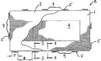
도 1은 잘라낸 물질의 상부 층을 갖는, 본 발명의 하나의 양태의 도식적인 상부 평면도이다.
도 2는 도 1에 도시된 양태의 도식적인 하부 평면도이다.
도 3은 도 1의 3-3 라인에 따른 단면도이다.
도 4는 도 1의 4-4 라인에 따른 단면도이다.
도 5는 2개의 보드의 이어진 엣지들을 도시한 제2 양태의 단면도이다.
도 6은 엣지를 확장하는 절단된 보드의 중심을 갖는, 도 5에서 도시된 종류의 단일 보드의 양태의 측면도이다.
도 7 내지 도 9는 단계들의 도식적인 평면도이고, 이로써 제2 양태의 보드는 조립될 수 있다.
도 10은 도 5에서부터 도 9까지 도시된 보드의 프레임 단독의 하부 평면도이다.
도 11은 도 10에 도시된 유형의 2개의 이어진 프레임의 상부 평면도이다.
도 12는 제3 양태에 따라 제조된 2개의 이어진 보드의 단면도이다.
도 13은 이들이 이어지기 전 제3 양태에 따라 만들어진 2개의 인접한 보드의 단면도이다.
도 14는 제3 양태에 따라 만들어진 2개의 이어진 프레임(부착된 상부 물질이 없이)의 단면도이다.
도 15는 제4 양태를 포함하는 스트립의 평면도이다.
도 16은 도 15에서 16-16 라인에 따른 도 15에 도시된 스트립의 단면도이다.1 is a schematic top plan view of one embodiment of the present invention having a top layer of cut material.
FIG. 2 is a schematic bottom plan view of the embodiment shown in FIG. 1. FIG.
3 is a cross-sectional view taken along the line 3-3 of FIG.
4 is a cross-sectional view taken along line 4-4 of FIG. 1.
5 is a cross-sectional view of a second aspect showing the contiguous edges of two boards.
FIG. 6 is a side view of an embodiment of a single board of the type shown in FIG. 5 with the center of a cut board extending edges. FIG.
7-9 are schematic plan views of the steps, whereby the board of the second aspect can be assembled.
FIG. 10 is a bottom plan view of the frame alone of the board shown in FIGS. 5-9.
FIG. 11 is a top plan view of two successive frames of the type shown in FIG. 10.
12 is a sectional view of two successive boards made in accordance with the third aspect.
13 is a cross-sectional view of two adjacent boards made according to the third aspect before they follow.
14 is a cross-sectional view of two successive frames (without top material attached) made in accordance with the third aspect.
15 is a plan view of a strip comprising a fourth aspect.
16 is a cross-sectional view of the strip shown in FIG. 15 along lines 16-16 in FIG.
본 명세서에 제시된 본 발명은 상기 기재된 도면 및 일부 특정한 예 또는 양태에 관해 기재된다. 3개의 양태가 기재되고, 이들은 단지 당해 분야의 숙련가에게 명백할 것인 많은 변형의 예에 불과하다. 이들은 도 1 내지 도 4에 묘사된 제1 양태, 도 5 내지 도 11에 도시된 제2 양태 및 도 12에 도시된 제3 양태를 포함한다.The invention presented herein is described with reference to the drawings described above and some specific examples or aspects. Three embodiments are described and these are merely examples of many variations that will be apparent to those skilled in the art. These include the first aspect depicted in FIGS. 1-4, the second aspect depicted in FIGS. 5-11, and the third aspect depicted in FIG. 12.
도 1은 이의 상부 표면이 둘 다 상부 물질(3)의 밑면에 부착된(당해 예에서는 접착제에 의해), 프레임(1) 및 필터 보드(4)를 포함하는 플로어 보드(8)의 일반적인 구조를 보여주는, 어느 정도는 현실적으로 도시된 상부 평면도이다. 필터 보드(4)는 프레임(1)에 맞고, 프레임(1)의 두께와 일반적으로 동일한 두께를 갖지만, 이들 부품의 상대적인 두께는 이들을 형성하는데 사용되는 물질의 상대적인 압축성에 따라 상이할 수 있고, 특히 상부 물질(3)이 아래놓인 부품, 즉 프레임(1) 및 필러 패널 또는 보드(4)와 상이한 두께에 따르는데 충분하게 가요성이 있는 경우, 특정한 외양을 달성하기 위해 다양할 수 있다.1 shows the general structure of a
도 2는 도 1에 도시된 보드(8)의 하부 평면도이다. 도 1 및 도 2에서, 혀(5)는 프레임(1)의 하부 엣지로부터 측면으로 확장되고, 혀(5)는 공간(9)에 의해 분리된다. 도 1 및 도 2에서 프레임(1)은 사출 성형된 내충격성 폴리스티렌의 단일 조각이지만, 프레임은, 예를 들면, 단순한 도브테일 연결에 의해 이어지거나 그렇지 않으면 부착된 2개의 L-형 섹션에 의해, 끝점에서 연결된 이러한 사출 성형된 플라스틱의 2개 이상의 조각으로 구성될 수 있다. 대안적인 양태에서, 프레임은 오목부가 없는 물질의 단일한 조각, 예를 들면, 바람직하게는 그와 일체형인 혀 및 바람직하게는 그 안에 일체형인 오목부를 갖는 플라스틱의 시트 또는 기타 물질로 교체될 수 있다. 각각의 혀(5)(당해 예에서)는 너비(T)를 갖고, 혀(5)는 하나 이상의 인접한 혀(5)로부터 거리(S)에 의해 분리된다. 도 1 및 도 2의 예에서, S 대 T의 비율은 2:1보다 크다. 공간(9)은 수치(S)를 갖고, 이는, 제1 보드의 혀(5)가 이어짐을 의도되는 제2 보드의 혀 사이에 용이하게 맞을 수 있도록, 적어도 너비(T) 이상(바람직하게는 이의 2배의 너비 이상)이어야 한다. 하나의 면 위의 혀의 위치는 반대면 위의 혀의 위치에 대해 엇갈리거나 보충한다. 당해 예에서, 하나의 면의 혀(5)는 동일한 보드의 반대면 위의 공간의 중심에 맞추어 조정된다. 당해 혀(5) 및 공간(9)의 엇갈린 배치는 장방형 보드(8)의 긴 면과 짧은 면 둘 다에 특유하다.FIG. 2 is a bottom plan view of the
도 3 및 도 4는 도 1 및 도 2에 도시된 보드의 엣지의 확대된 단면도이다. 도 3은 도 1의 3-3에 따른 도면이고, 혀(5)의 단면을 보여준다. 혀(5)의 중간 부분(18)은 베이스(19)로부터 확장된다. 상향 확장되는 돌출부(17)는 혀(5)의 원위 면에 배치된다. 돌출부(17)는 일반적으로 삼각형 모양이고, 경사진 코(11) 겉면은 일반적으로 보드(8)로부터 외부 및 위를 향한다. 혀(5)는 경사진 코(11)의 하부 엣지와 인접한 일반적으로 수직인 끝 표면(12)을 갖는다. 돌출부(17)는 일반적으로 평평한 상부 표면(16)을 포함하고, 이로부터 일반적으로 수직인 잠금 표면(14)은 아래로 중간 부분(18)의 상부에서 일반적으로 평평한 베어링 표면(20)응로 확장된다. 채널(15)은 혀(5)의 베이스(19)의 안쪽으로 배치된다. 채널(15)은 도 4에 나타낸 오목부(6)의 연속이다.3 and 4 are enlarged cross-sectional views of the edge of the board shown in FIGS. 1 and 2. 3 is a view according to 3-3 of FIG. 1, showing a cross section of the
도 4는 혀(5) 사이의 위치에서, 즉 공간(9)의 위치에서 보드(8)의 엣지를 통한 단면도이다. 도 4는 프레임(1)으로부터 아래 및 외부를 보는 경사진 표면(21)을 갖는 잠금 바(22)를 보여준다. 잠금 바(22)는 오목부(6)의 하나의 경계를 형성하는 일반적으로 수직인 잠금 표면(24)을 갖는다. 잠금 표면(24)은, 인접한 보드들이 이어질 때, 혀(5)의 돌출부(17) 위의 일반적으로 평평한 잠금 표면(20)에 맞물리도록 조정된다. 표면(14 및 24)이 일반적으로 수직인 것과 같이 본 명세서에 도시되는 반면, 이들은 하나의 각도(동일한 각도 또는 상이한 각도)를 가질 수 있고, 이들의 잠금 표면의 방향은 이어진 패널들 또는 보드들을 떼어내기보다 쉽게 또는 어렵게 만들도록 다양할 수 있음에 주의해야 한다. 오목부(6)는, 인접한 보드들이 이어질 때, 혀의 끝 위의 돌출부(17)의 상부 평평한 표면(16)에 대해 조정된 상부 표면(또는 천장)(23)을 갖는다.4 is a cross-sectional view through the edge of the
도 3 및 도 4에서, 수치 A 및 B는 각각 중간 부분(18)의 길이 및 잠금 표면(14)으로부터 보드(8)의 엣지의 외부 겉면(28)까지의 거리에 상응한다. 수치 B는 수치 A에 의해 한정되는 공간에 의해 수용되는 잠금 바(22)의 횡단면 길이이다. A 및 B 사이의 관계는, 프레임(1)의 제조 및 상부 물질(3)의 제조 둘 다에서, 도 12와 연결되어 하기 논의되는 바와 같이, 사용되는 물질의 마찰성 및 가요성 또는 유연한 물질이 사용되는 정도와 같은 기타 인자에 따라 다양할 수 있다. 갭이 없는 연결부위를 갖는 중요성 및 가능하게는 대체되고/거나 분리될 수 있는 패널 또는 보드의 중요성에 따라, 수치 A는 B보다 크거나, 동일하거나, 작을 수 있다.3 and 4, numerical values A and B correspond to the length of the
도 5 내지 도 11은 제2 양태의 부품을 보여준다. 제2 양태의 기재에서, 세자리 참조 숫자가 사용된다. 제1 양태와 유사한 구조가 제2 양태에 존재하고, 참조 숫자의 10의 자리수 및 1의 자리수는 제1 양태에 기재되는데 사용되는 두 자리수 참조 숫자에 상응하도록 선택된다.5-11 show a part of the second aspect. In the description of the second aspect, a three digit reference number is used. A structure similar to that of the first aspect is present in the second aspect, and the ten digits and one digit of the reference numeral are selected to correspond to the two digit reference numeral used to describe the first aspect.
도 5는 이어진 배열에서 2개의 보드(108)의 단면도이고, 도 6은 도 5에 나타낸 보드에 상응하는 보드(108)의 절단된 단면도이다. 제1 양태와 같이, 보드(108)는 프레임(101)의 상부 표면 및 필터 보드(104)의 상부 표면(절단된 형태에서 도 6에 도시됨)에 접착 층(107)(도 5에 도시되지만, 도 6에서는 너무 얇아서 도시되지 않음)에 의해 부착되는 상부 물질(103)(당해 예에서, 부각된 상부 장식용 층이 있는 고급 비닐 시트)을 포함한다. 도 5에서 좌측 면에서 보드(108)의 혀(105)의 원위 면 위의 잠금 돌출부(117)는 도 5에서 우측의 보드(108)의 밑면 위에 형성된 오목부(106)에 위치한다. 잠금 돌출부(117)는 혀(105)의 말단 끝으로부터 상향 확장되고, 오목부(106)의 내부로 마주보는 벽 위의 일반적으로 수직인 잠금 표면(124)과 인접하고 접촉하도록 조정되는 일반적으로 수직인 잠금 표면(114)을 갖는다. 혀(105)는 경사진 코(111)를 갖고, 그 아래에 평평한 일반적으로 수직인 표면(112)에 의해 한정된 뭉툭한 끝이 위치한다. 혀(105)의 원위 면은 잠금 바(122)의 하부 표면(126)에 접촉하고 인접한, 평평한 상부 표면(120)을 갖는 중간 부분(118)에 의해 베이스(119)에 이어진다. 잠금 바(122)는, 슬라이드-스냅핑 조립 동안, 경사진 코(111)과 공동 작용하여 실질적으로 동일평면상 위치를 형성하는 보드의 측면 이동에 의해 보드를 잇는 것을 촉진하는 아래 및 외부로 경사진 가이드 표면(121)을 갖는다.FIG. 5 is a cross sectional view of two boards 108 in a subsequent arrangement, and FIG. 6 is a cut sectional view of a board 108 corresponding to the board shown in FIG. Like the first aspect, the board 108 is shown in FIG. 5 with an adhesive layer 107 (shown in FIG. 5) on the top surface of the
제2 양태에서 상부 물질(103)은 바람직하게는 이로써 제한되지는 않지만, 당해 분야에 LVT(고급 비닐 타일) 시트로서 알려진 것과 같은 장식용 비닐 바닥 시트이다. 이러한 비닐 바닥 시트는 바람직하게는 비닐 클로라이드-함유 중합체 또는 PVC-무함유 바닥 커버링 비닐 중합체 물질로 만들어지고, 결국 상기 비닐 클로라이드-함유 중합체 또는 PVC-무함유 바닥 커버링 비닐 중합체 물질에 접착되는 중합체의 보호 코트가 장착된 부각된 상부 층을 갖는다.The
상부 물질(103)의 비닐 바닥 시트에 적합한 비닐 클로라이드-함유 중합체의 예는 가요성, 보행에 대한 내성, 청소 용이성 등과 같은 바람직한 성질의 조합을 갖는 임의의 이러한 비닐 중합체를 포함한다. 이들은 비닐 클로라이드의 단일중합체 및 공중합체를 포함한다.Examples of suitable vinyl chloride-containing polymers for the vinyl bottom sheet of the
상부 물질(103)의 비닐 바닥 시트에 적합한 PVC-무함유 바닥 커버링 비닐 중합체 물질은, 이로써 제한되지는 않지만, 가요성, 보행에 대한 내성, 청소 용이성 등과 같은 바람직한 성질의 조합을 갖는 낮은 밀도 또는 매우 낮은 밀도의 폴리에틸렌, 폴리프로필렌, 에틸렌-비닐 아세테이트 공중합체를 포함한다. 이들은 예를 들면, 제EP-0 528 194-B호에 기재된 바와 같은 멜트 인덱스가 0.3 내지 8.0g/10분(DIN 53 73에 따르면 190℃/2.16)인 에틸렌-비닐 아세테이트 공중합체를 포함한다.PVC-free floor covering vinyl polymer materials suitable for the vinyl floor sheet of the
기타 바닥 커버링 비닐 중합체 물질은 US 제6,287,706호, US 제5,458,953호, EP 제0603,310-B호 및 EP 제0528,194-B호에 기재되고, 이의 내용은 본 명세서에 참조로서 인용된다.Other bottom covering vinyl polymer materials are described in US Pat. No. 6,287,706, US Pat. No. 5,458,953, EP 0603,310-B and EP 0528,194-B, the contents of which are incorporated herein by reference.
상기 비닐 클로라이드-함유 중합체 또는 PVC-무함유 바닥 커버링 비닐 중합체 물질에 대한 중합체 접착제의 보호 코트는 유리 전이 온도, 파단시 신율 및 인장 강도와 같은 바람직한 성질의 조합을 갖는 임의의 피복 물질, 예를 들면, 이로써 제한되지는 않지만, 폴리우레탄 또는 폴리아크릴레이트 래커로 만들어질 수 있다.The protective coat of polymer adhesive on the vinyl chloride-containing polymer or PVC-free floor covering vinyl polymer material may be any coating material having a combination of desirable properties such as glass transition temperature, elongation at break and tensile strength, for example However, it may be made of polyurethane or polyacrylate lacquer.
비닐 클로라이드-함유 중합체 또는 PVC-무함유 바닥 커버링 비닐 중합체 물질은 당해 분야에 공지된 하나 이상의 유기 또는 무기 첨가제, 및/또는 유리 섬유 또는 기타 부직포 시스템의 형태로, 또는 안정화를 위한 PVC 또는 PVC-무함유 중합체 물질의 교차 방향 층 및 PVC 또는 PVC-무함유 중합체 물질로 만들어진 하부 표면 층의 사용에 의한 강화를 포함하는 PVC 또는 PVC-무함유 중합체 물질로 만들어진 하나 이상의 중간 지지체 또는 적재 층을 추가로 포함할 수 있다. 필터 보드(103)는 또한 비닐 시트이고, 장식용 상부 층을 갖는 대신에, 필터 보드의 상부 및 하부 겉면은 상부 물질(103)의 하부 표면으로써 동일한 물질을 갖는다.The vinyl chloride-containing polymer or PVC-free floor covering vinyl polymer material is in the form of one or more organic or inorganic additives known in the art, and / or glass fiber or other nonwoven systems, or PVC or PVC-free for stabilization. Further comprising one or more intermediate supports or loading layers made of PVC or PVC-free polymeric material, including reinforcement by use of cross-directional layers of containing polymeric material and bottom surface layers made of PVC or PVC-free polymeric materials. can do. The
접착제(107)는 내충격성 폴리스티렌(프레임(101)을 만든 플라스틱) 및 PVC(비닐 시트(103)의 밑면을 만든 물질) 둘 다에 잘 접착하는 것으로 알려진, 3M으로부터 구입 가능한 수성 네오프렌 접착제, 스카치-웰드(Scotch-Weld™) 30이다. 2개의 상이한 유형의 연결 방법(예를 들면, 접착제)이 사용되고, 즉 하나는 프레임(101)의 상부 표면에 상부 시트(103)의 밑면이 이어지고, 또 다른 하나는 필터 보드(102)의 상부 표면에 상부 시트(103)의 밑면이 이어지고, 단일한 연결 방법, 즉 모든 3개의 이어지는 표면들(비닐 상부 물질(103)의 밑면, 프레임의 상부 및 비닐 필터 보드의 상부)과 혼화성인 단일한 접착제가 바람직하다. 일반적인 표면과 프레임(101)의 물질 사이의 혼화성이 중요한 혼화성 요건이기 때문에, 상부 물질(103)의 하부 표면과 동일한 상부 표면을 갖도록 필터 보드(102)를 선택함으로써, 접착제의 선택은 단순화될 수 있다. 필터 보드의 물질이 이의 상부 표면이 상부 물질의 하부 또는 프레임의 상부 표면과 어울리지 않게 선택되는 경우, 사용되는 모든 3개의 물질(즉, 상부 물질의 하부, 필러 층의 상부 및 프레임의 상부)과 혼화성이되도록 선택되어야 하거나, 하나는 상부 물질을 필터 보드에 잇고, 또 다른 것은 상부 물질을 프레임에 잇는 2개의 상이한 연결 방법(예를 들면, 2개의 상이한 접착제)이 필요할 수 있다.The adhesive 107 is an aqueous neoprene adhesive, Scotch-, available from 3M, which is known to adhere well to both impact resistant polystyrene (plastic made of the frame 101) and PVC (material made of the base of the vinyl sheet 103). Welch (Scotch-Weld ™) 30. Two different types of connection methods (e.g. adhesives) are used, one of which is followed by the bottom of the
수치 A2(도 6에서 혀(105)의 중간 부분(118)의 측면 수치(lateral dimension))가 수치 B2(잠금 바(122)의 측면 수치)보다 실질적으로 크게 도시되는데, 도 5는 도시적으로 의도되는 것이고, 공학적인 도면으로 취급되지 말아야 한다. 추가로, 상기 논의된 바와 같이, 수치 A2 및 B2, 및 상부 물질(103)이 프레임(101)의 주변부 너머로 확장될 수 있는 정도와 같은 기타 수치는 보드(108)로 만들어진 연결부위가 더 단단하거나 덜 단단하게 만들어질 수 있도록 특정한 설계 목적에 따라 다양할 수 있다. 보드(108)가 상부 물질이 프레임보다 측면으로 크도록 만들어지는지 여부, 프레임 물질이 가요성을 갖는지 여부 및 보드가 이의 이어진 엣지들을 따라 이동할 수 있음이 필요한지 여부와 같은 인자에 따라, 수치 A2는 수치 B2보다 작거나 동일하거나 클 수 있다.The value A2 (lateral dimension of the
도 7, 8 및 9는 3개의 보드의 조립 동안 3개의 보드 B1, B2 및 B3의 일련의 위치를 보여주고, 여기서, 보드 B1 및 B2는 이의 각각의 긴 엣지의 부분이 연결되도록 먼저 이어진다. 당해 연결은 앵글링에 의해, 즉 보드 B2의 원위 면을 들어올리고, 몇몇 혀(105)를 보드 B1의 하나의 긴 면의 부분을 따라 공간(109)으로 몇몇 혀(105) 사이에 보드 B1의 근위 긴 면의 부분을 따라 삽입한 다음, 보드 B2를 보드 B1 쪽으로 누르면서 보드 B2의 원위 면을 낮춤으로써 제조할 수 있다. 보드 B3의 긴 면의 부분은 동일한 방식으로 보드 B1의 동일한 면의 또 다른 부분에 이어질 수 있지만, 서로 인접한 보드 B2 및 B3의 짧은 면과 도 7에 도시된 바와 같이 수행되어야 하고, 이로 인해 보드 B2 쪽으로 보드 B3의 약간의 이동이 이의 짧은 면들이 스냅핑 작용에 의해 서로를 맞물림을 야기할 것이다(도 9 참조). 보드 B2 및 B3의 짧은 면의 스냅핑 맞물림은 다음의 2가지 특징에 의해 가능하게 된다: 1) 도 7 및 도 8에 도시된 바와 같이, 수치 D2이 적어도 D1만큼 큰 결과를 야기하는, 혀(105)의 너비에 대한 공간(109) 크기의 관계 및 2) 도 7 내지 도 9에 도시된 바와 같이, 보드(108)의 대향하는 짧은 면(즉, 보드 B2의 오른쪽 짧은 면 및 보드 B3의 왼쪽 짧은 면) 위의 혀(105) 및 공간(109)의 보충성.7, 8 and 9 show a series of positions of the three boards B1, B2 and B3 during the assembly of the three boards, where the boards B1 and B2 are first followed so that the parts of their respective long edges are connected. This connection is achieved by angling, ie lifting the distal face of board B2, and placing
이러한 연결은 또한 보드 B2 및 B3의 긴 면은 보드 B1과 맞물림으로 앵글링될 수 있고, 이들 연결은 또한 슬라이드-스냅핑 작동에 의해, 즉, 예를 들면, 보드 B2(및/또는 B3)의 긴 면의 부분 위의 혀(105)를 보드 B1 위의 혀들 사이의 공간(109)에 맞춰 조정하고, 일반적으로 동일평면상인 보드를 서로를 향해 밀어냄으로써 달성할 수 있음을 주목해야 한다.This connection can also be angled with the long sides of the boards B2 and B3 engaged with the board B1, and these connections are also by slide-snapping operation, ie, for example, of the board B2 (and / or B3). It should be noted that the
도 7에서 화살표 M1은 보드(108)를 사용하는 바닥 커버링으로의 보드 B3의 2단계 조립에서 보드 B3의 첫번째 이동 방향을 보여줌을 의도한다. 상기 기재된 바와 같이 보드 B3은 보드 B1과 맞물림으로 앵글링 또는 스냅핑될 수 있다. 도 8에서, 화살표 M2는 보드 B2의 오른쪽 짧은 면과 보드 B3의 왼쪽 짧은 면의 스냅핑 맞물림을 보여줌을 의도한다. 보드 B3의 긴 면이 보드 B1의 긴 면과 미리 연결되었기 때문에, 보드 B3은 적어도 도 8에 도시된 위치로부터 보드 B2와 맞물림으로 들어올려지고 앵글링될 수 없다. 보드 B2 및 B3의 짧은 면을 앵글링 기술로 먼저 연결한 다음, 보드 B3을 보드 B1을 향해 이동시키고, 보드 B3 및 B1의 긴 면을 맞물리게 슬라이드-스냅핑함으로써 보드(108)로 커버링된 바닥을 형성할 수 있음을 주목해야 한다.Arrow M1 in FIG. 7 is intended to show the first direction of travel of board B3 in a two-step assembly of board B3 to the bottom covering using board 108. As described above, board B3 may be angled or snapped into engagement with board B1. In FIG. 8, arrow M2 is intended to show the snapping engagement of the right short side of board B2 with the left short side of board B3. Since the long side of the board B3 has been previously connected with the long side of the board B1, the board B3 cannot be lifted and angled with the board B2 from at least the position shown in FIG. Connect the short sides of boards B2 and B3 with angling technology first, then move board B3 towards board B1 and slide-snap the long sides of boards B3 and B1 to engage the bottom covered by board 108. It should be noted that it can be formed.
도 10 내지 도 14는 제3 양태의 부품을 보여준다. 제3 양태의 기재에서, 200대의 세자리 참조 숫자가 사용된다. 처음 2개의 양태와 유사한 구조가 제3 양태에 존재하고, 참조 숫자의 10의 자리 및 1의 자리는 제1 및 제2 양태를 기재하는데 사용된 두자릿수 참조 숫자에 상응하도록 선택된다.10-14 show a part of the third aspect. In the description of the third aspect, 200 three-digit reference numbers are used. Structures similar to the first two aspects are present in the third aspect, with the tens digit and one digit of the reference numeral selected to correspond to the two-digit reference numeral used to describe the first and second aspects.
도 10 내지 14는 본 명세서에 기재된 발명에 따라 만들어진 보드(208)의 제3 양태를 도시한다. 도 10은 보드(208)의 하부 평면도이다. 립(rib)(230) 및 보이드(232)는 프레임(201)의 밑면에 형성된다. 프레임의 밑면의 립과 보이드는 두 가지 목적을 제공한다: 1) 프레임(201)의 밑면과 지지 하부-바닥 사이의 겉면-대-겉면 접촉(및 결과적으로 소리의 전달)의 양을 줄이기 위함 및 2) 프레임(201)을 사출 성형하기 위해 사용되는 물질(당해 경우, 내충격성 폴리스티렌)의 양을 감소시키기 위함.10-14 illustrate a third aspect of a board 208 made in accordance with the invention described herein. 10 is a bottom plan view of the board 208.
제1 및 제2 양태와 같이, 혀(205)는 프레임(201)의 하부 엣지로부터 외향 확장되고, 이들 혀는 공간(209)에 의해 서로 분리된다. 도 11은 이의 전체 길이에 따라 이어진 이의 긴 면과 함께 이어진 2개의 보드(208)의 상부 평면도이다.As with the first and second aspects, the
도 12는 도 11에서 12-12 라인에 따른 2개의 보드(208)의 이어진 면들의 단면도이다. 당해 제3 양태에서 상부 물질(203)(이는 고급 비닐 시트지만, 또 다른 물질일 수 있고, 바람직하게는 카펫과 같이 반드시 가용성 물질일 필요는 없다)은 크기가 프레임(201)의 측면 수치보다 다소 크고, 이는 돌출부 립(234)을 형성하고, 이는 보드들이 이어지는 경우, 돌출부(217)의 잠금 표면(220)이 접촉하고 오목부(206)의 잠금 표면(224)에 대해 압력을 가함으로써, 서로에 대해 압력을 가한다.FIG. 12 is a cross-sectional view of successive faces of two boards 208 along line 12-12 in FIG. In this third embodiment the top material 203 (which is a high grade vinyl sheet, but may be another material, preferably not necessarily a soluble material such as a carpet), is somewhat smaller in size than the side value of the
도 13 및 14는 혀(205) 및 공간(209)(및 잠금 바(222) 및 오목부(206))의 위치에서 각각 2개의 보드 및 2개의 프레임의 측면 확대 단면도이다. 도 13에서, 혀(205)의 잠금 표면(214)은 다소 상향을 향하고 있고 수평에 대해 약 102도의 각도(L)에 있다. 잠금 바(222) 위의 잠금 표면(224)은 다소 하향 배치되고, 또한 수형에 대해 약 102도의 각도(L)로 배치된다. 도 14(오직 프레임 부분만을 도시, 즉 상부 물질 없음)에서, 잠금 표면(214 및 224)은 서로 접촉한다. 잠금 바(222)는 혀(205)의 중간 부분(218)의 상부 표면(220)에 의해 받쳐진다. 제1 양태와 같이, 혀(205)는 혀 베이스(219)로부터 확장된다. 혀 베이스(219) 및 중간 부분(218) 위에서, 보드(205)는 프레임(201)의 상부 엣지로부터 혀(205)에 이르기까지 확장되는 겉면(228)을 갖는다.13 and 14 are side enlarged cross-sectional views of two boards and two frames, respectively, in the position of
도 14는 잠금 표면(214 및 224)이 접촉할 때, 이어진 프레임들의 상부 겉면 사이의 너비(W)의 틈(235)을 보여준다. 도 13은 프레임(201)의 상부 겉면의 엣지 너머 외향 확장되는 상부 물질(203)의 돌출부 부분(234)을 보여준다. 돌출부 부분(234)의 측면 수치(H)는 바람직하게는 수치(W)의 절반보다 크고, 따라서 보드(208)가 연결될 때, 이어진 보드들의 돌출부 부분(234)은 수평으로 압축되고 변형되어 틈(235)을 덮는다. 상부 물질(203)의 압축성 및 변형성에 따라, 수치(H)는 수치(W)의 절반보다 아주 다소 클 수 있다. 선택된 상부 물질(203)의 강도 및 경도에 따라, 수치(H)는 W의 절반보다 작거나, W의 반과 동일하거나, W의 절반보다 클 수 있다. 비닐 시트 또는 카펫과 같이 용이하게 변형될 수 있는 물질의 경우, 돌출부 부분(234)의 수치(H)는 W의 절반보다 실질적으로 클 수 있다. 그러나, 더 강성이거나, 단단하거나, 더 잘 부러지는 물질의 경우, 돌출부 부분(234)의 수치(H)는 W의 절반보다 작거나 동일할 수 있다. 적절한 수치(H)를 결정하는 인자는 돌출부(217) 및 잠금 바(222)가 이의 접점에서 접촉 및 이어진 보드들의 상부 물질(203)의 엣지의 인접한 접촉으로부터 그 접점에서 힘에 대응하여 변형될 수 있도록 프레임 물질의 가요성이 존재하는지 여부이다.14 shows the
도 15 및 도 16은 제4 양태의 부품을 보여준다. 제4 양태의 기재에서, 300대의 세자리의 참조 숫자가 사용된다. 상기 기재된 양태와 유사한 구조가 제3 양태에 존재하고, 10의 자리 및 1의 자리의 참조 숫자는 제1 및 제2 양태를 설명하는데 사용된 두자리의 참조 숫자에 상응하도록 선택된다.15 and 16 show a part of the fourth aspect. In the description of the fourth aspect, 300 three-digit reference numbers are used. Structures similar to those described above exist in the third aspect, and reference numerals of the tens and ones positions are selected to correspond to the two-digit reference numerals used to describe the first and second aspects.
도 15 및 도 16은 보드(208) 사이에 장식용 구역을 제공하는데 사용될 수 있는 잠금 스트립(308)을 보여준다. 스트립은 세라믹 타일 또는 석재의 외양을 갖도록 만들어지거나 실제 세라믹 타일 또는 석재를 갖는 상부 물질(203)을 갖는 보드(208)와 사용에 적합하다. 스트립(308)의 상부 표면(303)은 모르타르 연결부위의 외양을 갖도록 오목하고 거칠고, 스트립을 형성하는데 사용되는 플라스틱(예를 들면, 내충격성 폴리스티렌 또는 기타 플라스틱)은 착색제와 함께 성형되어 추가의 장식용 또는 현실적인 외양을 제공할 수 있다. 4개의 보드가 만나고 4개의 스트립(301)이 모이는 모서리에서, 이러한 수렴한 끝에서 공백이 보이는 것을 최소화하도록, 스트립(301)의 말단은 약 90도로 배치된 각이 있는 표면(340 및 342)에 의해 형성된 뾰족한 끝(338)을 갖는다.15 and 16 show a locking strip 308 that can be used to provide a decorative zone between the boards 208. The strip is made to have the appearance of a ceramic tile or stone or is suitable for use with the board 208 having the
스트립(301)은 공간(309)에 의해 분리된 혀(305)를 갖고, 스트립(301)의 밑면은 혀(305) 사이에 잠금 바(322) 및 오목부(306)를 갖고, 혀(305), 바(332) 및 오목부(306)는 보드(208)의 엣지에서 유사한 혀(205) 및 잠금 바(222)와 맞고 연결되는 배열을 갖는다. 일반 치수의 보드(208)와 같이, 스트립(308)은 돌출부(317)가 있는 혀(305) 및 상부 표면(320)이 있는 중간 부분(318)을 갖는다. 돌출부(317)는 잠금 표면(314), 일반적으로 평평한 상부 표면(316), 경사진 코(311) 및 뭉툭한 끝(312)을 갖는다. 혀 위에 스트립의 상부 엣지 밑에 겉면(328)이 있다. 스트립 잠금은 혀(305) 사이에 공간(309), 및 이의 밑면에 오목부(306) 및 잠금 바(322)를 갖는다. 잠금 바는 경사진 가이드 표면(321) 및 잠금 표면(324)을 갖는다. 오목부(306)는 일반적으로 평평한, 잠금 표면(324) 및 상부 표면(323)에 의해 둘러싸인다. 오목부(306)는 인접한 보드가 그러하듯이 보드(208)의 혀(205)를 수용하도록 조정된다.The
상기 논의된 본 발명은 상부 물질용으로 LVT 또는 기타 비닐 시트, 카펫 및 HPL(고압 라미네이트), 평압(direct pressure) 라미네이트, 세라믹 타일, 니들 펠트, 목재, 종이, 인쇄되거나 인쇄되지 않은 플라스틱 물질을 포함하고, 필터 보드용으로 비닐 시트, PVC(폴리 비닐 클로라이드) 발포체(foam) 또는 EVA(에틸렌-비닐 아세테이트), 발포 EVA, TPE(열가소성 수지 엘라스토머, 예를 들면, 이로써 제한되지는 않지만, 에틸렌-프로필렌-디엔 공중합체), 폴리스티렌, 폴리에스테르, 폴리아미드 및 폴리올레핀(발포되거나 발포되지 않음)을 포함하고, 이들 모두는 상이한 구조/빌드(build)를 갖는 상이한 층들로 결국 이루어지고, 프레임 물질용으로 내충격성 폴리스티렌(HIPS), ABS(아크릴로니트릴 부타디엔 스티렌), PP(폴리프로필렌), PE(폴리에틸렌) 및 PA(폴리아미드)를 포함하는, 구조 및 물질의 몇몇 특정한 예에 관해 기재되었다. 상부 물질, 필터 보드 및 프레임의 연결에 관해, 조립체는 스카치-웰드 30 수성 네오프렌 접착제에 의해 이어지는 것으로 기재되었지만, 이어지는 물질들에 따라 기타 기술, 예를 들면, 핫멜트, PA-핫멜트, 반응성 핫멜트, 용매계 네오프렌 접착제, 기타 수계 네오프렌 접착제, 용매 용접, 열 용접, 열성형 및 초음파 용접이 사용될 수 있다. 그러나, 이들 물질은 오직 예시이고 본 발명의 범위를 제한함을 의도하지 않는다. 실제로, 당해 분야의 숙련가는 특정한 분야 또는 설계 목적에 의해 요구되거나 제안될 수 있는 기타 물질을 선택할 수 있다. 본 발명은 상기 기재된 양태 또는 첨부된 도면에 의해 제한되지 않는다. 반면, 이러한 보드는 아래에 청구된 본 발명의 범위 내에 남아 있으면서 상이한 물질, 형태 및 수치로 만들어질 수 있다.The invention discussed above includes LVT or other vinyl sheets, carpets and HPLs (high pressure laminates), direct pressure laminates, ceramic tiles, needle felts, wood, paper, printed or unprinted plastic materials for the top materials. And vinyl sheet, PVC (polyvinyl chloride) foam or EVA (ethylene-vinyl acetate), foamed EVA, TPE (thermoplastic elastomer), such as, but not limited to, for filter boards Diene copolymers), polystyrene, polyesters, polyamides and polyolefins (foamed or unfoamed), all of which eventually consist of different layers with different structures / builds, Including impact polystyrene (HIPS), ABS (acrylonitrile butadiene styrene), PP (polypropylene), PE (polyethylene) and PA (polyamide) , Some specific examples of structures and materials have been described. Regarding the connection of the upper material, the filter board and the frame, the assembly has been described as being followed by a Scotch-Weld 30 aqueous neoprene adhesive, but according to the following materials other techniques such as hotmelt, PA-hotmelt, reactive hotmelt, solvent Systemic neoprene adhesives, other aqueous neoprene adhesives, solvent welding, thermal welding, thermoforming and ultrasonic welding can be used. However, these materials are illustrative only and are not intended to limit the scope of the present invention. Indeed, those skilled in the art may select other materials that may be required or suggested by a particular field or design purpose. The invention is not limited by the embodiments described above or the accompanying drawings. Such boards, on the other hand, may be made of different materials, forms, and values while remaining within the scope of the invention as claimed below.
실시예Example
본 명세서에 기재된 플로어 보드의 양태를 이의 음향성에 대해 시험하였다. 양태는 도 10 내지 14에 관해 상기 기재된 제3 양태의 설계이고, 이는 하기 결과 표에서 "양태 3"으로 기재된다. 시험된 양태 3에서 프레임은 사출 성형된 내충격성 폴리스티렌으로 만들어지고, 모든 걸쇠 혀들은 프레임의 면들과 일체형이고, 모든 오목부는 프레임의 밑면에 형성되었다. 필터 보드는 프레임의 두께와 동일한 3.6mm의 두께를 갖는 발포되지 않은 PVC의 시트였다. 상부 물질은 고급 비닐 타일 물질의 것이고, 캘린더링된 PVC의 4개 층을 갖고, 이의 하부 2개 층은 스트레칭되고 완화되도록 하였고, 각각은 서로에 대해 90°로 스트레칭의 지향성을 갖고, 최상층으로부터 두번째 층은 인쇄된 PVC 층이고, 최상층은 투명 마모 PVC 층이었다. 함께, 캘린더링된 PVC의 4개 층은 2mm의 총 두께를 가졌다. 마모 최상층(top wear layer)은 0.3mm의 두께를 가졌다. 음향 시험 방법론 및 시험 결과는 하기에 제공한다.Embodiments of the floor boards described herein were tested for their acoustic properties. The embodiment is the design of the third embodiment described above with respect to FIGS. 10-14, which is described as “
시험 방법Test Methods
건축 음향에서, 소리 전달의 상이한 2가지 방식이 알려져 있다. 첫 번째 방식은 드럼 소리로도 알려진, 동일한 방에서 건축 구성요소에 의해 반사된 소리가다. 두 번째 방식은 인접한 방에서 건축 구성요소를 통한 소리의 전달이다.In architectural sound, two different ways of transmitting sound are known. The first is the sound reflected by architectural components in the same room, also known as drum sounds. The second method is the transmission of sound through architectural components in adjacent rooms.
소리 반사 또는 드럼 소리에 있어서, 다수의 표준이 존재한다. 널리 사용되는 표준은 2004년 10월 29일 버전의 EPLF021029-3(European Producers of Laminate Flooring)이다. 측정 방법은 반무향실에서 표준 태핑 머신에 의한 측정을 기준으로 한다. 시험 샘플을 콘크리트 바닥에 설치하고 하중하에 시험한다. 8개의 태핑 위치 및 4개의 마이크 위치를 측정을 위해 사용한다.There are a number of standards for sound reflection or drum sound. A widely used standard is the European Producers of Laminate Flooring (EPLF021029-3) of the October 29, 2004 version. The measurement method is based on the measurement by a standard tapping machine in a semi anechoic chamber. Test samples are installed on the concrete floor and tested under load. Eight tapping positions and four microphone positions are used for the measurement.
각각의 측정은 EPLF에 의해 전달된, 참조 바닥에 대해 수행된다. 참조 바닥 및 시험 바닥 둘 다의 음압 레벨은 250 내지 6300Hz 스펙트럼에서 사용으로 측정된다.Each measurement is performed on a reference floor, delivered by EPLF. Sound pressure levels of both the reference and test floors are measured for use in the 250-6300 Hz spectrum.
즈비커 교수(Prof. Zwicker)에 의한 음량의 심리음향학적 정의에 따라, 후-측정 계산은 반사된 소리의 음량을 설명하고, 단일 값 음량 N으로서 결과를 표현한다.According to the psychoacoustic definition of volume by Prof. Zwicker, post-measurement calculations account for the volume of the reflected sound and express the result as a single value volume N.
음량 N은 ISO 532:1975에서 한정되고, 소리의 감지된 강도를 측정하는 표준화된 방법이다. 음량 개념은 히어링 방식의 주파수 의존성을 포함한다. 단위는 손(sone)이다. 1손은 40dB에서 1kHz톤에 상응한다. 음량은 선형 측정이다. 손 값의 배가는 감지된 음량의 배가를 야기한다.Volume N is defined in ISO 532: 1975 and is a standardized way of measuring the perceived intensity of sound. The volume concept includes the frequency dependence of the hearing method. Units are hands. One hand corresponds to a 1 kHz tone at 40 dB. Volume is a linear measure. The doubling of the hand value causes a doubling of the sensed volume.
각각 샘플의 4개의 가장 낮은 측정값은 평균내어 Nm 값이 된다.The four lowest measurements of each sample are averaged to the Nm value.
참조 바닥과 시험 바닥 사이의 차이는 %로 계산하고 음량에서 감소를 제공한다.The difference between the reference floor and the test floor is calculated in% and gives a decrease in volume.
참조 바닥과 비교하여 백분율 감소에 따라, 시험된 바닥을 하기 감소를 갖는 분류 SL0 부터 SL60 또는 그 이상으로 분류한다.Depending on the percentage reduction compared to the reference floor, the tested floor is sorted from classification SL0 to SL60 or higher with the following reduction.

시험 결과Test result
다수의 구조를 시험하였고, 그 결과는 다음과 같다:A number of structures were tested and the results are as follows:

상기 표에서 바닥 타입 1 내지 5는 비교 목적으로 시험된, 시중에서 구입할 수 있는 바닥을 대표한다. 예상외로 양태 3은 시험된 모든 통상적인 LVT 제품보다 우수하게 수행하였다. 추가로, 심지어 2.5mm PP 밑깔개 발포체 위에 설치된 경우에도, 라미네이트 바닥 시험을 능가한다.Floor types 1-5 in the table above represent commercially available floors tested for comparison purposes. Unexpectedly,
당해 적용에서 기재된 양태의 보행 소음(드럼 소리/반사된 소리)은 명백하게 유리하다.Walking noise (drum sound / reflected sound) of the embodiments described in this application is clearly advantageous.
접촉 소리로도 알려진 소리 전달에 있어서, 널리 사용되는 표준은 ISO 140-1:1997, ISO 140-2:1991, ISO 717-2:1996 및 EN 5079:1990을 참고로 하여, ISO 140-6:1998, ISO 140-8:1997이다. 이러한 표준 집합은 건축 구성요소를 통한 인접실에 소리 전달을 측정하는 방법을 설명한다.In sound transmission, also known as contact sound, widely used standards are referred to ISO 140-1: 1997, ISO 140-2: 1991, ISO 717-2: 1996 and EN 5079: 1990, and ISO 140-6: 1998, ISO 140-8: 1997. This set of standards describes how to measure sound transmission to adjacent rooms through architectural components.
요약하면, 측정은 하기에 따라 수행된다:In summary, the measurements are performed as follows:
- 140mm 콘크리트 바닥(참조 바닥)을 샘플 바닥과 맞춘다.-Fit the 140 mm concrete floor (reference floor) with the sample floor.
- 당해 바닥 아래 수음실(receiving room)이 위치한다.A receiving room is located below the floor.
- ISO 140-6 Annex A에 기재된 바와 같이, 표준 해머링 머신으로 소리를 만든다.Make sound with a standard hammering machine, as described in ISO 140-6 Annex A.
- 샘플 바닥 및 참조 바닥 위의 상이한 5개의 위치에서 측정한다.Measure at five different positions above the sample bottom and the reference bottom.
- 측정을 위해, 회전 마이크를 사용하고, 테르츠 밴드(terz band)에서 필터링한다. 이로써 신호의 시간 및 공간 평균을 수득한다.For measurement, use a rotary microphone and filter in the terz band. This gives the temporal and spatial averages of the signals.
- 접촉 소리 레벨 Ln을 하기와 같이 계산한다:The contact sound level Ln is calculated as follows:
Ln = Li + 10 log(A/A0) (dB 단위)Ln = Li + 10 log (A / A0 ) in dB
여기서,here,
- Li은 수음실에서 테르츠 밴드 당 음압 레벨(dB 단위)이고,Li is the sound pressure level per dB band in the receiving room,
- A0은 참조면(㎡ 단위)이고,A 0 is the reference plane in
- A는 수음실의 동등한 흡수면(㎡ 단위)이다.-A is the equivalent absorption surface of the receiving chamber in
그 다음, 접촉 소리 개선 ΔLW을 참조 바닥 대 시험 바닥에서 음압 레벨의 차이로서 표현한다(dB 단위).The contact sound improvement ΔLW is then expressed as the difference in sound pressure level at the reference floor versus the test floor (in dB).
몇몇 표준 바닥 품질에 있어서, 하기 결과를 수득하였다:For some standard floor qualities, the following results were obtained:

하기 결과를 도출할 수 있다:The following results can be obtained:
- 양태 3은 밑깔개 없이 사용되는 경우 통상적인 LVT를 능가한다(데시벨 규모는 대수적임을 주의해야 한다).
- 양태 3은 밑깔개와 결합하여 사용되는 경우 다른 바닥 타입과 동일한 성능을 가졌다.
상기 기재된 음향 연구로부터 일반적인 결론은 본 발명의 양태는 드럼 소리/보행 소음 시험에서 라미네이트 바닥 커버링과 동일하거나 더욱 우수한 성능을 갖고, 소리 전달 시험에서 동일한 성능을 갖는다는 것이다.A general conclusion from the acoustic studies described above is that aspects of the present invention have the same or better performance than laminate floor coverings in drum sound / walking noise tests, and the same performance in sound transmission tests.
상기 실시예는 매우 우수한 수준의 방음재 뿐만 아니라 순응성에서 임의의 개선, 설치의 용이성 및 상이한 패턴으로 조립할 수 있는 가능성으로 이루어진 본 발명의 양태에 의해 제공된 잇점을 명백하게 보여준다.This example clearly shows the advantages provided by the aspects of the present invention, which consist of not only a very good level of sound insulation but also any improvement in compliance, ease of installation and the possibility of assembling in different patterns.
Claims (30)
Translated fromKorean상기 상부 물질은 노출된 상부 겉면 및 밑면을 갖고, 상기 필터 보드는 상기 프레임에 의해 한정된 공간 내에 놓이고; 상기 상부 물질의 상기 밑면은 상기 프레임의 상부 표면에 부착되고; 상기 상부 물질의 상기 밑면은 상기 필터 보드의 상부 표면에 부착되고; 상기 프레임은 상기 프레임으로부터 외향 확장되는 복수의 걸쇠 혀들(latch tongue)을 갖고; 상기 프레임은 적어도 하나의 상기 걸쇠 혀에 맞물리기 위해 이의 밑면에 형성된 적어도 하나의 오목부를 갖고, 각각의 보드의 상기 걸쇠 혀 및 적어도 하나의 상기 오목부는, 제1 보드의 상기 혀가, 인접한 제2 보드의 오목부와 맞물리도록 배열되는, 보드.A board comprising a frame, a top material, and a filter board,
The top material has an exposed top face and bottom face, and the filter board is placed in a space defined by the frame; The underside of the upper material is attached to the upper surface of the frame; The underside of the top material is attached to the top surface of the filter board; The frame has a plurality of latch tongues extending outwardly from the frame; The frame has at least one recess formed in its underside to engage at least one of the clasp tongues, wherein the clasp tongue and at least one recess of each board, wherein the tongue of the first board is adjacent to the second A board, arranged to engage a recess of the board.
상기 상부 물질은 장식용 상부 겉면 및 밑면을 갖고, 상기 필터 보드는 상기 프레임에 의해 한정된 공간 내에 놓이고; 상기 탄성 비닐 시트의 밑면은 상기 프레임의 상부 표면에 부착되고; 상기 상부 물질의 밑면은 상기 필터 보드의 상부 표면에 부착되고; 상기 프레임은, 상기 프레임으로부터 상부 물질의 외곽 영역 너머로 외향 확장하는 복수의 걸쇠 혀들을 갖고; 상기 프레임은, 상기 플로어 보드의 적어도 하나의 걸쇠 혀에 맞물리게 하기 위해, 이의 밑면에 형성된 적어도 하나의 오목부를 갖고, 각각의 보드의 걸쇠 혀들은 공간들에 의해 분리되고, 상기 공간들은 적어도 상기 혀들 중의 임의의 것의 최대 너비만큼은 넓은 너비를 갖고, 상기 보드 위의 상기 혀는, 상기 보드가, 실질적으로 유사한 배열로 배치된 혀들 및 공간들을 갖는 또 다른 보드의 임의의 면에 부착될 수 있도록 배치되는, 플로어 보드.A floor board comprising a frame made of injection molded plastic, a top material comprising an elastic vinyl sheet, and a filter board comprising a sound absorbing material, comprising:
The upper material has a decorative upper face and a bottom, and the filter board is placed in a space defined by the frame; An underside of the elastic vinyl sheet is attached to an upper surface of the frame; An underside of the upper material is attached to an upper surface of the filter board; The frame has a plurality of clasp tongues extending outwardly from the frame beyond the outer region of the upper material; The frame has at least one recess formed in its base to engage at least one clasp tongue of the floor board, the clasp tongues of each board are separated by spaces, the spaces being at least one of the tongues. The maximum width of anything has a wide width and the tongue on the board is arranged such that the board can be attached to any side of another board having tongues and spaces arranged in a substantially similar arrangement, Floor board.
각각의 보드는 프레임, 상부 물질, 및 필터 보드를 포함하고; 상기 상부 물질은 노출된 상부 겉면 및 밑면을 갖고, 상기 필터 보드는 상기 프레임에 의해 한정된 공간 내에 놓이고; 상기 상부 물질의 상기 밑면은 상기 프레임의 상부 표면에 부착되고; 상기 상부 물질의 상기 밑면은 상기 필터 보드의 상부 표면에 부착되고; 상기 프레임은 상기 프레임으로부터 외향 확장되는 복수의 걸쇠 혀들을 갖고; 상기 프레임은 이의 밑면에 형성된 적어도 하나의 오목부를 갖고; 상기 오목부의 외부면은, 적어도 하나의 걸쇠 혀에 맞물리기 위해 잠금 바에 의해 둘러싸이고, 각각의 보드의 상기 걸쇠 혀들 및 상기 잠금 바는, 제1 보드의 혀들이 제2 인접한 보드의 오목부와 맞물리도록 배치되고, 상기 상부 물질은, 상기 프레임의 상부 엣지들 너머로 확장되는 돌출부 부분들을 형성하는 엣지들을 갖는, 보드들의 조립체.As an assembly of boards,
Each board comprises a frame, a top material, and a filter board; The top material has an exposed top face and bottom face, and the filter board is placed in a space defined by the frame; The underside of the upper material is attached to the upper surface of the frame; The underside of the top material is attached to the top surface of the filter board; The frame has a plurality of clasp tongues extending outwardly from the frame; The frame has at least one recess formed in its underside; The outer surface of the recess is surrounded by a locking bar for engaging at least one clasp tongue, wherein the clasp tongues and the locking bar of each board engage the recess of the second adjacent board with the tongues of the first board. And the top material has edges forming protrusion portions extending beyond the top edges of the frame.
상기 4면 보드는 이로부터 외향 확장되는 각각의 면 위에 복수의 걸쇠 혀들을 갖고,
각각의 걸쇠 혀들은 상향 확장된 돌출부를 갖고; 상기 보드는, 상기 걸쇠 혀들 중의 적어도 하나의 상기 상향 확장되는 돌출부와 맞물리기 위해 이의 밑면에 위치한 적어도 하나의 잠금 바를 갖고; 여기서, 상기 프레임의 각각의 면에 따른 상기 걸쇠 혀들은, 상기 프레임의 반대면 위의 걸쇠 혀들의 위치들에 대해 엇갈린 위치들에 놓이고; 상기 보드 위의 각각의 걸쇠 혀들은 너비를 갖고, 각각의 상기 걸쇠 혀들은, 최소 공간에 의해 동일한 면 위의 인접한 걸쇠 혀로부터 분리되고; 보드의 임의의 면이 동일한 배열의 또 다른 보드의 임의의 면에 연결될 수 있도록, 보드 위의 걸쇠 혀들 사이의 최소 공간은 적어도 보드 위의 가장 넓은 걸쇠 혀만큼 넓은, 보드.As a four sided board,
The four-sided board has a plurality of clasp tongues on each side extending outwardly therefrom,
Each clasp tongue has an upwardly extending protrusion; The board has at least one locking bar located on its underside to engage the upwardly extending protrusion of at least one of the clasp tongues; Wherein the clasp tongues along each side of the frame are in staggered positions relative to the positions of the clasp tongues on opposite sides of the frame; Each clasp tongue on the board has a width, and each of the clasp tongues are separated from adjacent clasp tongues on the same side by a minimum space; The minimum space between the clasp tongues on the board is at least as wide as the widest clasp tongue on the board so that any face of the board can be connected to any face of another board in the same arrangement.
Applications Claiming Priority (5)
| Application Number | Priority Date | Filing Date | Title |
|---|---|---|---|
| CN201010203493.0ACN101881076B (en) | 2010-06-09 | 2010-06-09 | Combined floor capable of being paved conveniently |
| CN201010203493.0 | 2010-06-09 | ||
| CNPCT/CN2010/001304 | 2010-08-27 | ||
| PCT/CN2010/001304WO2011075933A1 (en) | 2009-12-23 | 2010-08-27 | Conveniently paved floor |
| PCT/CN2011/075085WO2011153916A1 (en) | 2010-06-09 | 2011-06-01 | Floor board assembly |
Related Child Applications (1)
| Application Number | Title | Priority Date | Filing Date |
|---|---|---|---|
| KR1020177024372ADivisionKR101925235B1 (en) | 2010-06-09 | 2011-06-01 | Floor board assembly |
Publications (1)
| Publication Number | Publication Date |
|---|---|
| KR20130132376Atrue KR20130132376A (en) | 2013-12-04 |
Family
ID=43053201
Family Applications (2)
| Application Number | Title | Priority Date | Filing Date |
|---|---|---|---|
| KR1020177024372AExpired - Fee RelatedKR101925235B1 (en) | 2010-06-09 | 2011-06-01 | Floor board assembly |
| KR1020137000557ACeasedKR20130132376A (en) | 2010-06-09 | 2011-06-01 | Floor board assembly |
Family Applications Before (1)
| Application Number | Title | Priority Date | Filing Date |
|---|---|---|---|
| KR1020177024372AExpired - Fee RelatedKR101925235B1 (en) | 2010-06-09 | 2011-06-01 | Floor board assembly |
Country Status (15)
| Country | Link |
|---|---|
| US (1) | US8726603B2 (en) |
| EP (1) | EP2414603A4 (en) |
| JP (1) | JP2013529272A (en) |
| KR (2) | KR101925235B1 (en) |
| CN (1) | CN101881076B (en) |
| AU (2) | AU2011264257B2 (en) |
| BE (1) | BE1021461B1 (en) |
| BR (1) | BR112012031235B1 (en) |
| CA (1) | CA2752195C (en) |
| MX (1) | MX2012014383A (en) |
| NZ (1) | NZ720894A (en) |
| RU (1) | RU2598614C2 (en) |
| UA (1) | UA113276C2 (en) |
| WO (2) | WO2011153916A1 (en) |
| ZA (1) | ZA201209499B (en) |
Families Citing this family (52)
| Publication number | Priority date | Publication date | Assignee | Title |
|---|---|---|---|---|
| BE1017157A3 (en) | 2006-06-02 | 2008-03-04 | Flooring Ind Ltd | FLOOR COVERING, FLOOR ELEMENT AND METHOD FOR MANUFACTURING FLOOR ELEMENTS. |
| US8728603B2 (en) | 2006-12-11 | 2014-05-20 | Ulrich Windmöller Consulting GmbH | Floor panel |
| MY152779A (en)* | 2008-01-31 | 2014-11-28 | Valinge Innovation Ab | Mechanical locking of floor panels, methods to install and uninstall panels, a method and an equipment to produce the locking system, a method to connect a displaceable tongue to a panel and a tongue blank |
| PL2518237T3 (en)* | 2009-12-23 | 2018-03-30 | Hong Kong Mei Li Sheng Flooring Co., Limited | Conveniently paved floor |
| CN101881076B (en)* | 2010-06-09 | 2014-07-09 | 黄焕文 | Combined floor capable of being paved conveniently |
| CN102251650A (en)* | 2011-04-26 | 2011-11-23 | 黄焕文 | Combined floor convenient for spreading |
| CN103074988A (en)* | 2011-10-25 | 2013-05-01 | 泰州市华丽塑料有限公司 | Double-layer composite plastic floor |
| ITMO20120070A1 (en)* | 2012-03-16 | 2013-09-17 | Claudio Gozzi | PROCEDURE FOR THE PRODUCTION OF A MODULAR COMPOSITE MANUFACTURING FOR THE COATING OF SURFACES AND MANUFACTURED ITEMS. |
| ITTV20130006A1 (en)* | 2013-01-18 | 2014-07-19 | New Tile Di Girotto Ambra | STRUCTURE OF MODULAR TILE |
| US9194134B2 (en) | 2013-03-08 | 2015-11-24 | Valinge Innovation Ab | Building panels provided with a mechanical locking system |
| US9340984B2 (en)* | 2013-07-28 | 2016-05-17 | Alan Lun Chou | Micro lock mortise riveted joint frame two ply solid wood hybrid engineered flooring |
| US20160265223A1 (en)* | 2013-11-01 | 2016-09-15 | 9290-9043 Quebec Inc. | Suspended ceiling system and tile therefore |
| CA2967054C (en)* | 2013-11-12 | 2020-09-01 | Yugang ZHONG | Modular flooring |
| WO2015130169A1 (en) | 2014-02-26 | 2015-09-03 | Innovations 4 Flooring Holding N.V. | Panel interconnectable with similar panels for forming a covering |
| GB2510724B (en)* | 2014-03-03 | 2015-02-18 | Wai Ying Wong | Connecting floor boards |
| ES2822958T3 (en)* | 2014-04-10 | 2021-05-05 | Berryalloc Nv | Floor board with universal connection system |
| US10293571B2 (en) | 2014-05-20 | 2019-05-21 | Euro Trade Flooring, S.L. | Multilayer lining plate for horizontal support |
| ES2551632B1 (en)* | 2014-05-20 | 2016-09-08 | Euro Trade Flooring, S.L. | Multi-layer cladding plate for horizontal support surfaces and manufacturing process |
| BE1021929B1 (en) | 2014-07-04 | 2016-01-27 | Unilin Bvba | FLOOR PANEL |
| CN104088425A (en)* | 2014-07-13 | 2014-10-08 | 吴燕珊 | Combined-type brick easy to install |
| CN204225424U (en)* | 2014-10-16 | 2015-03-25 | 福州亿利达木业有限公司 | A kind of framework wood flooring |
| US9249582B1 (en) | 2014-11-14 | 2016-02-02 | Awi Licensing Company | Interlocking floor panels with high performance locking profiles |
| US9394697B2 (en)* | 2014-12-10 | 2016-07-19 | Afi Licensing Llc | Flooring system |
| CA2925721C (en)* | 2015-03-31 | 2017-08-01 | Gestion Mcd Inc. | Tile system for suspended ceiling and wall, and method |
| US9896851B1 (en)* | 2015-04-14 | 2018-02-20 | The Matworks Copmany LLC | Hard surface veneer and wood polymer composite flooring tile |
| PT108736B (en)* | 2015-07-29 | 2022-05-04 | Nuno Miguel Simoes Vicente | SYSTEM FOR CONNECTION AND FITTING METHOD OF MODULES FOR FLOOR COVERING BETWEEN EACH OTHER |
| WO2017044739A1 (en)* | 2015-09-10 | 2017-03-16 | Comc, Llc | Modular flooring assemblies |
| ITUA20163458A1 (en)* | 2016-05-16 | 2016-08-16 | MODULAR ELEMENT WITH SUPERIOR DEFORMABLE COVERED SUPPORT PLATE. | |
| US10626622B2 (en)* | 2016-07-06 | 2020-04-21 | Super-Click Technology Co., Ltd. | Assembled floor unit |
| BE1024723B1 (en) | 2016-11-10 | 2018-06-11 | Ivc Bvba | Floor panel and method for manufacturing a floor panel. |
| USD854711S1 (en) | 2017-04-05 | 2019-07-23 | Oshkosh Floor Designs Acquisition, LLC | Modular flooring tile |
| US10774292B2 (en) | 2017-05-11 | 2020-09-15 | Ecolab Usa Inc. | Compositions and method for floor cleaning or restoration |
| ES2902394T3 (en)* | 2017-05-15 | 2022-03-28 | Flooring Ind Ltd Sarl | A floor element for forming a floor covering and a floor covering |
| CN207620259U (en)* | 2017-07-19 | 2018-07-17 | 上海协承昌化工有限公司 | A kind of plank and its decoration panel |
| EP3450653A1 (en)* | 2017-09-01 | 2019-03-06 | Tarkett GDL S.A. | Kit for making a floor covering |
| ES2983349T3 (en)* | 2017-10-25 | 2024-10-22 | Lignum Tech Ag | Floor system with improved flexibility |
| NL2020972B1 (en)* | 2018-05-23 | 2019-12-02 | Innovations4Flooring Holding N V | Multi-purpose tile system, tile covering, and tile |
| BE1026806B1 (en) | 2018-11-27 | 2020-06-30 | Flooring Ind Ltd Sarl | Panel and method of manufacturing such panel |
| WO2020109961A1 (en) | 2018-11-27 | 2020-06-04 | Flooring Industries Limited, Sarl | Panel and method for manufacturing such a panel |
| US10677275B1 (en)* | 2019-02-18 | 2020-06-09 | Daltile Corporation | Floor element for forming a floor covering, a floor covering and a method for manufacturing a floor element |
| WO2020176974A1 (en)* | 2019-03-06 | 2020-09-10 | Gestion Mcd Inc. | Tile system for ceiling and wall |
| NL2022925B1 (en)* | 2019-04-11 | 2020-10-20 | Northann Building Solutions LLC | Decorative panel, panel covering, and method of producing such a decorative panel |
| WO2021026600A1 (en)* | 2019-08-13 | 2021-02-18 | LWC Research Pty Ltd | Prefabricated floor panel, construction and method therefor |
| US11559961B2 (en) | 2019-09-17 | 2023-01-24 | Daltile Corporation | Pressing equipment, a plant and a method for forming a floor element |
| US11339576B2 (en) | 2019-09-17 | 2022-05-24 | Daltile Corporation | Floor element for forming a floor covering and a floor covering |
| WO2021123978A1 (en)* | 2019-12-17 | 2021-06-24 | Flooring Industries Limited, Sarl | Polymer floor element |
| BE1027869B1 (en)* | 2019-12-17 | 2021-07-15 | Ivc Bv | POLYMER FLOOR ELEMENT |
| NL2025115B1 (en)* | 2020-03-12 | 2021-10-19 | Northann Building Solutions LLC | Decorative surface covering element, surface covering element covering, and method of producing such a decorative surface covering element |
| NL2028247B1 (en)* | 2021-05-19 | 2022-12-06 | J Van Klinken Holding B V | Interlockable wall reinforcement panel, wall reinforcement assembly and method for wall reinforcement |
| MA60164A1 (en)* | 2023-05-02 | 2024-12-31 | Benachir Asmaa | PAPER-BASED ORNAMENTAL MOSAIC SURFACE COVERING MATERIAL AND METHOD FOR MANUFACTURING SAME |
| CN116607718A (en)* | 2023-05-26 | 2023-08-18 | 常州市豪优杰智能科技有限公司 | Dry paving ceramic tile structure and paving method |
| WO2025004058A1 (en)* | 2023-06-26 | 2025-01-02 | Vox Interior And Exterior Solutions Private Limited | Interlocking panel |
Family Cites Families (61)
| Publication number | Priority date | Publication date | Assignee | Title |
|---|---|---|---|---|
| US357144A (en)* | 1887-02-01 | Hale to j | ||
| US2900676A (en)* | 1955-11-04 | 1959-08-25 | Kahr Gustaf | Laminated parquet boards |
| GB857025A (en) | 1956-12-28 | 1960-12-29 | Charles Ashton Waller | Improvements in or relating to skirting members for use between floors and walls |
| US3310919A (en)* | 1964-10-02 | 1967-03-28 | Sico Inc | Portable floor |
| US3667153A (en)* | 1969-07-03 | 1972-06-06 | Interlego Ag Zug | Interlocking arrangements |
| US5136823A (en)* | 1989-08-25 | 1992-08-11 | Pellegrino John V | Device for cladding architectural shingles |
| DE4127107C1 (en) | 1991-08-16 | 1992-12-24 | Tarkett Pegulan Ag, 6710 Frankenthal, De | |
| US5458953A (en) | 1991-09-12 | 1995-10-17 | Mannington Mills, Inc. | Resilient floor covering and method of making same |
| GB9124952D0 (en) | 1991-11-23 | 1992-01-22 | Hill Anthony Designs | Dance floor assembly |
| GB9415930D0 (en)* | 1994-08-04 | 1994-09-28 | Forbo Nairn Ltd | Floor coverings |
| JPH0828015A (en)* | 1994-07-14 | 1996-01-30 | Kawai Musical Instr Mfg Co Ltd | Floor material for soundproofing |
| MX9702105A (en)* | 1994-09-22 | 1997-06-28 | Johannes Mueller-Hartburg | Panels in particular for floor, wall, ceiling or furniture coverings or components, a method of manufacturing such panels or components, and a retaining element for such panels. |
| SE9500810D0 (en)* | 1995-03-07 | 1995-03-07 | Perstorp Flooring Ab | Floor tile |
| BE1010487A6 (en) | 1996-06-11 | 1998-10-06 | Unilin Beheer Bv | FLOOR COATING CONSISTING OF HARD FLOOR PANELS AND METHOD FOR MANUFACTURING SUCH FLOOR PANELS. |
| AT405560B (en)* | 1997-06-18 | 1999-09-27 | Kaindl M | ARRANGEMENT OF COMPONENTS AND COMPONENTS |
| CN2356094Y (en)* | 1998-12-31 | 1999-12-29 | 谢勇成 | Floor tile |
| JP3818002B2 (en) | 2000-02-21 | 2006-09-06 | 株式会社Inax | Floor tile unit |
| DE50002949D1 (en)* | 2000-03-07 | 2003-08-21 | E F P Floor Prod Fussboeden | Panel, especially floor panel |
| CN2491539Y (en) | 2001-06-15 | 2002-05-15 | 上海金刚环保建材有限公司 | Assembly floor structure |
| EP1277896A1 (en)* | 2001-07-16 | 2003-01-22 | Ulf Palmberg | Floorboards |
| SE525558C2 (en)* | 2001-09-20 | 2005-03-08 | Vaelinge Innovation Ab | System for forming a floor covering, set of floorboards and method for manufacturing two different types of floorboards |
| CN2505415Y (en)* | 2001-10-26 | 2002-08-14 | 万宝林 | Combined spliced packing box |
| US6694691B2 (en) | 2002-01-22 | 2004-02-24 | Chen Chung Ku | Combination floor pad having composite base boards |
| US20030136070A1 (en)* | 2002-01-22 | 2003-07-24 | Ku Chen Chung | Combination floor pad having composite base boards |
| SE525661C2 (en)* | 2002-03-20 | 2005-03-29 | Vaelinge Innovation Ab | Floor boards decorative joint portion making system, has surface layer with underlying layer such that adjoining edge with surface has underlying layer parallel to horizontal plane |
| US6793586B2 (en) | 2002-04-03 | 2004-09-21 | David R. Barlow | Golf putting and chipping practice green |
| US6802159B1 (en) | 2002-05-31 | 2004-10-12 | Snap Lock Industries, Inc. | Roll-up floor tile system and the method |
| JP4579231B2 (en)* | 2003-02-24 | 2010-11-10 | ベーリンゲ、イノベイション、アクチボラグ | Floor board and manufacturing method thereof |
| DE10355788B4 (en)* | 2003-11-26 | 2008-02-07 | Meyer, Hans | Plate for use in a laying system, in particular for the production of a floor covering and method for producing the same |
| PT1554954E (en)* | 2004-01-13 | 2007-10-23 | Berry Finance Nv | Carpet tiles |
| US8201377B2 (en)* | 2004-11-05 | 2012-06-19 | Faus Group, Inc. | Flooring system having multiple alignment points |
| US7610731B1 (en) | 2005-01-10 | 2009-11-03 | Comc, Llc | Snap together floor structure |
| CN2780891Y (en)* | 2005-01-26 | 2006-05-17 | 侯盼领 | Color rubber floor tile |
| CN2799735Y (en)* | 2005-03-14 | 2006-07-26 | 罗生权 | Floor with interval plastic positioning clamp |
| US7461482B2 (en)* | 2005-04-13 | 2008-12-09 | Cerasi Mark A | Sub-flooring assembly and method |
| CA2520434C (en)* | 2005-09-20 | 2013-01-08 | Covermaster Inc. | Multipurpose protective surface cover |
| US7543417B2 (en)* | 2005-10-04 | 2009-06-09 | Comc, Llc | Modular flooring assemblies |
| JP5111756B2 (en) | 2005-11-30 | 2013-01-09 | 永大産業株式会社 | Board and floor structure for actual joining |
| US7155871B1 (en) | 2005-12-29 | 2007-01-02 | Tru Woods Limited | Floor plank |
| SE530653C2 (en)* | 2006-01-12 | 2008-07-29 | Vaelinge Innovation Ab | Moisture-proof floor board and floor with an elastic surface layer including a decorative groove |
| CA2576889A1 (en)* | 2006-02-06 | 2007-08-06 | Insca Internacional, S.L. | Device for joining parquet-type plaques or pieces |
| KR200423549Y1 (en)* | 2006-05-23 | 2006-08-08 | 김경환 | Building flooring |
| US8316606B2 (en)* | 2006-06-08 | 2012-11-27 | Siewert Cabinet & Fixture Manufacturing, Inc. | Fastening system for panels and trim |
| CN101215923A (en)* | 2007-01-06 | 2008-07-09 | 王仁忠 | Frame type wooden floor |
| WO2008088239A1 (en) | 2007-01-18 | 2008-07-24 | Yury Andreevich Kutsenko | Connection joint for structural panels |
| SE532207C2 (en)* | 2007-03-14 | 2009-11-17 | Kaehr Ab G | Floor-laying system, profile rail and floor-board for such floor-laying system Procedure for laying conduit elements in the floor-laying system as well as uses of the floor-laying system for various purposes |
| CN101532331A (en)* | 2007-07-30 | 2009-09-16 | 诺瓦利斯股份有限公司 | Floor covering with interlocking design |
| CN101148941A (en) | 2007-10-11 | 2008-03-26 | 金月华 | Composite floor board with filling material at central layer |
| US8505257B2 (en)* | 2008-01-31 | 2013-08-13 | Valinge Innovation Ab | Mechanical locking of floor panels |
| JP2009197507A (en)* | 2008-02-22 | 2009-09-03 | Hayashi Bussan Hatsumei Kenkyusho:Kk | Double-faced block |
| CN101280620B (en)* | 2008-03-28 | 2010-06-02 | 罗生权 | Floor plastic rubber lock catch convenient for connecting and positioning |
| KR101050399B1 (en)* | 2008-05-20 | 2011-07-19 | 현대산업개발 주식회사 | Waterproof method using a plurality of waterproof sheets |
| WO2010012116A1 (en)* | 2008-07-29 | 2010-02-04 | Giesbrecht + Partner Ag | Surface cladding system |
| CN101502360A (en)* | 2009-03-19 | 2009-08-12 | 海宁市亚通线缆有限责任公司 | Combined wood-plastic screen board |
| CN201495736U (en)* | 2009-08-28 | 2010-06-02 | 唐宪涛 | Floor |
| PL2518237T3 (en) | 2009-12-23 | 2018-03-30 | Hong Kong Mei Li Sheng Flooring Co., Limited | Conveniently paved floor |
| CN101718142B (en)* | 2009-12-23 | 2012-04-18 | 黄焕文 | Convenient-to-lay flooring |
| CN101881076B (en) | 2010-06-09 | 2014-07-09 | 黄焕文 | Combined floor capable of being paved conveniently |
| CN101775891B (en) | 2010-02-08 | 2012-03-07 | 黄焕文 | Convenient-laying floor board with good decorative effect |
| CN201747023U (en)* | 2010-02-08 | 2011-02-16 | 黄焕文 | Floor with convenient laying and decorative effect |
| CN201704926U (en)* | 2010-06-09 | 2011-01-12 | 黄焕文 | Easy-laying combined-type floorboard |
- 2010
- 2010-06-09CNCN201010203493.0Apatent/CN101881076B/ennot_activeExpired - Fee Related
- 2011
- 2011-01-06UAUAA201300280Apatent/UA113276C2/enunknown
- 2011-06-01CACA2752195Apatent/CA2752195C/enactiveActive
- 2011-06-01BRBR112012031235Apatent/BR112012031235B1/ennot_activeIP Right Cessation
- 2011-06-01NZNZ720894Apatent/NZ720894A/ennot_activeIP Right Cessation
- 2011-06-01JPJP2013513533Apatent/JP2013529272A/ennot_activeWithdrawn
- 2011-06-01KRKR1020177024372Apatent/KR101925235B1/ennot_activeExpired - Fee Related
- 2011-06-01AUAU2011264257Apatent/AU2011264257B2/ennot_activeCeased
- 2011-06-01USUS13/201,332patent/US8726603B2/enactiveActive
- 2011-06-01KRKR1020137000557Apatent/KR20130132376A/ennot_activeCeased
- 2011-06-01MXMX2012014383Apatent/MX2012014383A/enunknown
- 2011-06-01WOPCT/CN2011/075085patent/WO2011153916A1/enactiveApplication Filing
- 2011-06-01RURU2012157228/03Apatent/RU2598614C2/ennot_activeApplication Discontinuation
- 2011-06-08EPEP11741078.7Apatent/EP2414603A4/ennot_activeWithdrawn
- 2011-06-08WOPCT/CN2011/075450patent/WO2011153940A1/enactiveApplication Filing
- 2011-11-24BEBE2011/0678Apatent/BE1021461B1/ennot_activeIP Right Cessation
- 2012
- 2012-12-13ZAZA2012/09499Apatent/ZA201209499B/enunknown
- 2016
- 2016-04-27AUAU2016202663Apatent/AU2016202663B2/ennot_activeCeased
Also Published As
| Publication number | Publication date |
|---|---|
| JP2013529272A (en) | 2013-07-18 |
| NZ720894A (en) | 2018-02-23 |
| AU2016202663A1 (en) | 2016-05-19 |
| US8726603B2 (en) | 2014-05-20 |
| EP2414603A1 (en) | 2012-02-08 |
| AU2011264257A1 (en) | 2013-01-24 |
| BR112012031235A2 (en) | 2016-10-25 |
| CN101881076B (en) | 2014-07-09 |
| WO2011153940A1 (en) | 2011-12-15 |
| WO2011153916A1 (en) | 2011-12-15 |
| CA2752195C (en) | 2018-09-04 |
| BE1021461B1 (en) | 2015-11-26 |
| UA113276C2 (en) | 2017-01-10 |
| ZA201209499B (en) | 2013-08-28 |
| CN101881076A (en) | 2010-11-10 |
| US20120317911A1 (en) | 2012-12-20 |
| AU2016202663B2 (en) | 2018-08-09 |
| RU2012157228A (en) | 2014-07-20 |
| BR112012031235B1 (en) | 2019-12-17 |
| CA2752195A1 (en) | 2011-12-09 |
| KR20170102577A (en) | 2017-09-11 |
| RU2598614C2 (en) | 2016-09-27 |
| KR101925235B1 (en) | 2019-02-22 |
| AU2011264257B2 (en) | 2016-01-28 |
| EP2414603A4 (en) | 2014-12-03 |
| MX2012014383A (en) | 2013-02-11 |
Similar Documents
| Publication | Publication Date | Title |
|---|---|---|
| KR101925235B1 (en) | Floor board assembly | |
| US11795701B2 (en) | Floor covering with interlocking design | |
| US20230407645A1 (en) | Wall or floor covering element | |
| EP3722534A1 (en) | Set of moisture proof floorboards | |
| US20200032526A1 (en) | Acoustic panelling for producing a floor covering | |
| US20060272260A1 (en) | Floor system and floor with a plurality of floor panels | |
| UA82085C2 (en) | Floor board (variants) and method to make it (variants) | |
| US11220827B2 (en) | Floor underlayment | |
| GB2510724A (en) | Modular flooring having seperate interlocking boards and connectors | |
| JPS63268627A (en) | Preparation of vibration and sound insulating plate for setting on floor |
Legal Events
| Date | Code | Title | Description |
|---|---|---|---|
| PA0105 | International application | Patent event date:20130108 Patent event code:PA01051R01D Comment text:International Patent Application | |
| PG1501 | Laying open of application | ||
| A201 | Request for examination | ||
| PA0201 | Request for examination | Patent event code:PA02012R01D Patent event date:20150604 Comment text:Request for Examination of Application | |
| E902 | Notification of reason for refusal | ||
| PE0902 | Notice of grounds for rejection | Comment text:Notification of reason for refusal Patent event date:20160920 Patent event code:PE09021S01D | |
| AMND | Amendment | ||
| E601 | Decision to refuse application | ||
| PE0601 | Decision on rejection of patent | Patent event date:20170330 Comment text:Decision to Refuse Application Patent event code:PE06012S01D Patent event date:20160920 Comment text:Notification of reason for refusal Patent event code:PE06011S01I | |
| AMND | Amendment | ||
| PX0901 | Re-examination | Patent event code:PX09011S01I Patent event date:20170330 Comment text:Decision to Refuse Application Patent event code:PX09012R01I Patent event date:20161121 Comment text:Amendment to Specification, etc. | |
| PX0601 | Decision of rejection after re-examination | Comment text:Decision to Refuse Application Patent event code:PX06014S01D Patent event date:20170601 Comment text:Amendment to Specification, etc. Patent event code:PX06012R01I Patent event date:20170502 Comment text:Decision to Refuse Application Patent event code:PX06011S01I Patent event date:20170330 Comment text:Amendment to Specification, etc. Patent event code:PX06012R01I Patent event date:20161121 Comment text:Notification of reason for refusal Patent event code:PX06013S01I Patent event date:20160920 | |
| PA0104 | Divisional application for international application | Comment text:Divisional Application for International Patent Patent event code:PA01041R01D Patent event date:20170830 |