KR20130132233A - Arm unit and robot having the same - Google Patents
Arm unit and robot having the sameDownload PDFInfo
- Publication number
- KR20130132233A KR20130132233AKR1020120131721AKR20120131721AKR20130132233AKR 20130132233 AKR20130132233 AKR 20130132233AKR 1020120131721 AKR1020120131721 AKR 1020120131721AKR 20120131721 AKR20120131721 AKR 20120131721AKR 20130132233 AKR20130132233 AKR 20130132233A
- Authority
- KR
- South Korea
- Prior art keywords
- link
- contact
- links
- cloud
- arm unit
- Prior art date
- Legal status (The legal status is an assumption and is not a legal conclusion. Google has not performed a legal analysis and makes no representation as to the accuracy of the status listed.)
- Granted
Links
Images


Classifications
- A—HUMAN NECESSITIES
- A61—MEDICAL OR VETERINARY SCIENCE; HYGIENE
- A61B—DIAGNOSIS; SURGERY; IDENTIFICATION
- A61B34/00—Computer-aided surgery; Manipulators or robots specially adapted for use in surgery
- A61B34/70—Manipulators specially adapted for use in surgery
- A61B34/71—Manipulators operated by drive cable mechanisms
- A—HUMAN NECESSITIES
- A61—MEDICAL OR VETERINARY SCIENCE; HYGIENE
- A61B—DIAGNOSIS; SURGERY; IDENTIFICATION
- A61B17/00—Surgical instruments, devices or methods
- A61B17/00234—Surgical instruments, devices or methods for minimally invasive surgery
- A—HUMAN NECESSITIES
- A61—MEDICAL OR VETERINARY SCIENCE; HYGIENE
- A61B—DIAGNOSIS; SURGERY; IDENTIFICATION
- A61B34/00—Computer-aided surgery; Manipulators or robots specially adapted for use in surgery
- A61B34/30—Surgical robots
- B—PERFORMING OPERATIONS; TRANSPORTING
- B25—HAND TOOLS; PORTABLE POWER-DRIVEN TOOLS; MANIPULATORS
- B25J—MANIPULATORS; CHAMBERS PROVIDED WITH MANIPULATION DEVICES
- B25J9/00—Programme-controlled manipulators
- B25J9/06—Programme-controlled manipulators characterised by multi-articulated arms
- B25J9/065—Snake robots
- B—PERFORMING OPERATIONS; TRANSPORTING
- B25—HAND TOOLS; PORTABLE POWER-DRIVEN TOOLS; MANIPULATORS
- B25J—MANIPULATORS; CHAMBERS PROVIDED WITH MANIPULATION DEVICES
- B25J9/00—Programme-controlled manipulators
- B25J9/10—Programme-controlled manipulators characterised by positioning means for manipulator elements
- B25J9/104—Programme-controlled manipulators characterised by positioning means for manipulator elements with cables, chains or ribbons
Landscapes
- Engineering & Computer Science (AREA)
- Health & Medical Sciences (AREA)
- Surgery (AREA)
- Life Sciences & Earth Sciences (AREA)
- Robotics (AREA)
- Heart & Thoracic Surgery (AREA)
- Nuclear Medicine, Radiotherapy & Molecular Imaging (AREA)
- Biomedical Technology (AREA)
- Medical Informatics (AREA)
- Molecular Biology (AREA)
- Animal Behavior & Ethology (AREA)
- General Health & Medical Sciences (AREA)
- Public Health (AREA)
- Veterinary Medicine (AREA)
- Mechanical Engineering (AREA)
- Manipulator (AREA)
Abstract
Description
Translated fromKorean암 유닛 및 이를 포함하는 로봇에 관한 것이다.It relates to an arm unit and a robot including the same.
최소침습수술이란 환부의 크기를 최소화하는 수술을 통칭하는 것으로 대표적인 예로서 복강경 수술이 있다. 최소침습수술은 기존의 개복수술과 달리 배를 완전히 열고 수술을 하는 것이 아니라, 몇 개의 작은 절개공을 내고 배에 가스를 채워 수술 공간을 만든 후, 절개공을 통해 복강경(Laparoscope)과 수술용 작동기(Manipulator)를 넣어 영상을 보면서 수술용 작동기로 수술을 하는 방법이다.Minimally invasive surgery is a general operation that minimizes the size of the affected area, and a typical example is laparoscopy. Minimally invasive surgery, unlike the previous surgery, does not open the abdomen and open the abdomen. Instead, it makes several small incisions and fills the gas to create a surgical space. Then, the laparoscope and the actuator are made through the incision. Put a (Manipulator) to watch the image to operate with a surgical actuator.
복강경 수술은 개복수술과 달리 수술 후 통증이 적고, 입원 기간이 짧으며, 정상 상태로의 복귀가 빠르고, 절개 범위가 적어 미용효과가 우수하다는 장점을 가진다. 그러나 조정하기 힘든 수술용 작동기와 절개공을 통하여서만 수술용 작동기를 움직여야 하는 단점이 있다.Laparoscopic surgery, unlike open surgery, has the advantages of less pain after surgery, shorter hospital stays, faster return to normal conditions, and a smaller incision range. However, there is a disadvantage that the surgical actuator must be moved only through the surgical actuator and the incision which are difficult to adjust.
이러한 복강경 수술의 단점을 보완하기 위해 절개공을 하나만 내는 Single Port 수술 내지 절개공을 하나도 형성하지 않고 입, 항문 등과 같은 자연 개구부를 통해 수술용 작동기를 삽입하여 수술을 수행하는 자연 개구부 수술(Natural Orifice Translumenal Endoscopic Surgery ; NOTES)이 최근 활발히 연구되고 있다.In order to make up for the shortcomings of laparoscopic surgery, natural orifice surgery is performed by inserting a surgical actuator through a natural opening such as mouth and anus without forming single incision or single incision. Translumenal Endoscopic Surgery (Notes) has been actively studied recently.
이러한 Single Port 수술 또는 자연 개구부 수술을 원활히 수행하기 위해서는 수술용 작동기의 암이 굴곡이 있는 환자의 내부 또는 장기를 따라 지나갈 수 있도록 유연성을 가져야 함과 동시에 수술부위에서는 가해지는 하중을 견딜 수 있도록 강성을 가져야 한다.In order to perform such a single port operation or a natural opening operation smoothly, the arm of the surgical actuator needs to be flexible to pass along the internal or organ of the curved patient, and at the same time, it is rigid to withstand the load applied to the surgical site. Should have
상황에 따라 간편하게 강성을 변경할 수 있도록 개선된 구조를 가지는 암 유닛 및 이를 포함하는 로봇을 개시한다.Disclosed is an arm unit having an improved structure so that the rigidity can be easily changed according to a situation, and a robot including the same.
기술적 사상의 일 측면에 따른 로봇은 암(arm) 유닛;과, 상기 암 유닛을 구동하기 위한 구동유닛;을 포함하고, 상기 암 유닛은, 적어도 둘 이상의 영역으로 서로 구름 접촉(rolling contact)하는 복수의 링크;와, 상기 복수의 링크를 관통 연결하는 복수의 와이어;를 포함하는 것을 특징으로 한다.According to an aspect of the inventive concept, a robot includes an arm unit and a driving unit for driving the arm unit, wherein the arm unit includes a plurality of rolling contacts with at least two regions. A link; and a plurality of wires connecting through the plurality of links.
상기 복수의 링크는 일렬로(serial) 배치되고, 상기 복수의 링크 중 적어도 두 개의 링크는 서로 이웃하는 다른 링크와 구름 접촉할 수 있다.The plurality of links may be arranged in a line, and at least two of the plurality of links may be in cloud contact with another link adjacent to each other.
상기 복수의 링크 중 적어도 하나의 링크는, 그 중심부가 중공된 형상의 몸체와, 상기 적어도 하나의 링크와 이웃하는 다른 링크를 향하는 제1방향으로 상기 몸체가 굴곡되어 형성되는 복수의 제1구름 접촉부를 포함할 수 있다.At least one of the plurality of links includes a body having a hollow shape at a central portion thereof, and a plurality of first cloud contact portions formed by bending the body in a first direction toward another link adjacent to the at least one link. It may include.
상기 제1방향과 반대되는 제2방향으로 상기 몸체가 굴곡되어 형성되는 복수의 제2구름 접촉부를 포함할 수 있다.The body may include a plurality of second cloud contact parts formed by bending the body in a second direction opposite to the first direction.
상기 복수의 제1구름 접촉부는 상기 몸체가 연장되는 방향을 따라 상기 몸체의 중심을 관통하는 중심선을 기준으로 180°회전된 위치에 배치되는 한 쌍으로 마련될 수 있다.The plurality of first cloud contact portions may be provided as a pair disposed at positions rotated by 180 ° with respect to a center line penetrating the center of the body in a direction in which the body extends.
상기 복수의 제2구름 접촉부는 상기 몸체가 연장되는 방향을 따라 상기 몸체의 중심을 관통하는 중심선을 기준으로 180°회전된 위치에 배치되는 한 쌍으로 마련될 수 있다.The plurality of second cloud contact portions may be provided as a pair disposed at positions rotated by 180 ° with respect to a center line penetrating the center of the body in a direction in which the body extends.
상기 제1구름 접촉부는 상기 몸체가 연장되는 방향을 따라 상기 몸체의 중심을 관통하는 중심선을 기준으로 상기 제2구름 접촉부와 90°회전된 위치에 배치될 수 있다.The first cloud contact portion may be disposed at a position rotated 90 ° with the second cloud contact portion with respect to a center line passing through the center of the body in a direction in which the body extends.
상기 제1구름 접촉부는 상기 이웃하는 다른 링크와 구름 접촉하는 구름 접촉면을 포함할 수 있다.The first cloud contact portion may include a cloud contact surface in cloud contact with another neighboring link.
상기 구름 접촉면의 적어도 일 부분은 일정한 곡률을 가지는 원의 일부일 수 있다.At least a portion of the rolling contact surface may be part of a circle having a constant curvature.
상기 복수의 링크는, 제1링크와, 상기 몸체가 연장되는 방향을 따라 상기 링크의 중심을 관통하는 중심선을 기준으로 상기 제1링크와 90°회전된 위치에서 상기 제1링크의 상부 또는 하부와 구름 접촉하는 제2링크를 포함할 수 있다.The plurality of links may include a first link and an upper or lower portion of the first link at a position rotated by 90 ° with the first link with respect to a center line passing through the center of the link in a direction in which the body extends. It may include a second link in cloud contact.
상기 제1링크와 상기 제2링크 사이에 위치하여 상기 제1링크와 상기 제2링크 간의 미끄럼(slip)을 방지하는 미끄럼방지부재를 더 포함 할 수 있다.The non-slip member may be further disposed between the first link and the second link to prevent slippage between the first link and the second link.
상기 미끄럼방지부재의 일면은 상기 제1링크의 일부분과 접하고, 타면은 상기 제2링크의 일부분과 접할 수 있다.One surface of the non-slip member may contact a portion of the first link, and the other surface may contact a portion of the second link.
상기 제2링크와 대향하는 상기 제1링크의 제1면과 상기 제1면과 구름 접촉하는 상기 제2링크의 제2면에는 각각 상기 제1링크와 상기 제2링크 간의 미끄럼(slip)을 방지하기 위해 서로 맞물리는 제1치형부 및 제2치형부가 마련될 수 있다.The first surface of the first link facing the second link and the second surface of the second link in contact with the first surface prevent slip between the first link and the second link, respectively. The first tooth portion and the second tooth portion may be provided to engage each other.
상기 제1치형부는 그 중심부가 중공된 형상으로 마련되는 상기 제1링크의 원주방향을 따라 상기 제1면에 형성되고, 상기 제2치형부는 그 중심부가 중공된 형상으로 마련되는 상기 제2링크의 원주방향을 따라 상기 제2면에 형성될 수 있다.The first tooth portion is formed on the first surface along the circumferential direction of the first link having a central portion thereof in a hollow shape, and the second tooth portion of the second link portion has a hollow portion in its central portion. It may be formed on the second surface along the circumferential direction.
상기 제1구름 접촉부의 높이는 서로 다를 수 있다.Heights of the first cloud contact portions may be different from each other.
상기 복수의 링크는, 그 상면과 하면이 이웃하는 다른 링크와 모두 구름 접촉하는 제1링크와, 그 상면과 하면 중 어느 하나의 면은 이웃하는 다른 링크와 구름 접촉하고, 다른 하나의 면은 이웃하는 다른 링크와 서로 상대 회전할 수 없도록 면 접촉하는 제2링크와, 그 상면과 하면이 이웃하는 다른 링크와 서로 상대 회전할 수 없도록 모두 면 접촉하는 제3링크를 포함할 수 있다.The plurality of links may include a first link in which the upper surface and the lower surface of the plurality of clouds contact the neighboring links, and one of the upper surface and the lower surface is in cloud contact with another neighboring link, and the other surface is neighboring. The second link may be in surface contact so as not to rotate relative to each other, and the third link may be in surface contact so that the upper and lower surfaces thereof may not rotate relative to each other.
상기 제2링크는 상기 제1링크와 상기 제3링크 사이에 배치될 수 있다.The second link may be disposed between the first link and the third link.
상기 제3링크는 적어도 둘 이상이 서로 이웃하도록 배치되어 상기 암 유닛이 구동되는 과정에서 강체(rigid body)를 형성할 수 있다.The third link may be arranged such that at least two of the third links are adjacent to each other to form a rigid body in the process of driving the arm unit.
상기 복수의 와이어는, 상기 제1구름 접촉부를 상기 복수의 링크가 배치되는 방향으로 관통하는 한 쌍의 제1와이어와, 상기 제2구름 접촉부를 상기 복수의 링크가 배치되는 방향으로 관통하는 한 쌍의 제2와이어를 포함할 수 있다.The plurality of wires may include a pair of first wires penetrating the first cloud contact portion in a direction in which the plurality of links are arranged, and a pair penetrating the second cloud contact portions in a direction in which the plurality of links are arranged. It may include a second wire of.
상기 암 유닛이 구동되는 과정에서 상기 한 쌍의 제1와이어 중 어느 하나가 늘어나는 길이는 다른 하나가 줄어드는 길이와 다를(non-symmetric) 수 있다.In the process of driving the arm unit, the length in which one of the pair of first wires is extended may be different from the length in which the other is reduced (non-symmetric).
상기 제1와이어 및 상기 제2와이어에 가해지는 장력(tension)과 상기 암 유닛의 강성(stiffness)은 서로 비례할 수 있다.The tension applied to the first wire and the second wire and the stiffness of the arm unit may be proportional to each other.
상기 구동유닛은, 상기 제1와이어 및 상기 제2와이어의 경로를 변경하는 적어도 하나의 풀리와, 상기 제1와이어 및 상기 제2와이어에 가해지는 장력을 조절할 수 있도록 상기 제1와이어 및 상기 제2와이어와 연결되는 구동 플레이트를 포함할 수 있다.The drive unit may include at least one pulley for changing a path of the first wire and the second wire, and the first wire and the second wire to adjust the tension applied to the first wire and the second wire. It may include a drive plate connected with the wire.
또한, 기술적 사상의 다른 측면에 따른 로봇은 복수의 링크를 포함하는 암 유닛과, 상기 암 유닛을 구동하기 위한 구동유닛을 포함하는 로봇에 있어서, 상기 링크는, 그 중심부가 중공된 형상의 몸체;와, 상기 몸체 상부면 및 하부면 중 적어도 하나의 일부 구간이 상기 몸체의 길이 방향으로 돌출 형성되어 상기 링크와 이웃하는 다른 링크와 구름 접촉하는 적어도 하나의 볼록부;를 포함하는 것을 특징으로 한다.In addition, the robot according to another aspect of the technical idea is a robot including a arm unit including a plurality of links, and a drive unit for driving the arm unit, the link, the center of the hollow hollow shape; And at least one convex portion protruding in the longitudinal direction of the body from at least one of the upper and lower surfaces of the body to make a cloud contact with another link adjacent to the link.
상기 링크는 상기 볼록부와 연결되는 적어도 하나의 오목부를 포함하고, 상기 오목부는 상기 링크 및 상기 링크와 이웃하는 다른 링크가 상기 볼록부를 통해 상대 회동할 수 있도록 회동 공간을 형성할 수 있다.The link may include at least one concave connected to the convex portion, and the concave portion may form a rotation space such that the link and another link neighboring the link may rotate relative to the convex portion.
상기 볼록부는 상기 몸체의 중심을 관통하는 중심선을 포함하는 가상의 제1분할면을 기준으로 서로 대향하는 위치에 배치되는 한 쌍으로 마련될 수 있다.The convex portions may be provided as a pair disposed at positions facing each other with respect to the virtual first divided surface including a center line penetrating through the center of the body.
상기 오목부는 상기 제1분할면과 직교하는 가상의 제2분할면을 기준으로 서로 대향하는 위치에 배치되는 한 쌍으로 마련될 수 있다.The recesses may be provided as a pair disposed at positions facing each other with respect to the virtual second divided surface orthogonal to the first divided surface.
상기 볼록부는 이웃하는 다른 링크와 구름 접촉하는 구름 접촉면을 포함하고, 상기 구름 접촉면의 적어도 일 부분은 일정한 곡률을 가지는 원의 일부일 수 있다.The convex portion includes a cloud contact surface in cloud contact with another neighboring link, and at least a portion of the cloud contact surface may be part of a circle having a constant curvature.
상기 복수의 링크는 제1링크와, 상기 제1링크와 동일한 형상을 가지며, 상기 제1링크의 상부면 및 하부면과 이웃하는 제2링크 및 제3링크를 포함하고, 상기 제1링크는, 그 중심부가 중공된 형상의 몸체와, 상기 몸체 상부면의 일부 구간이 상기 몸체의 길이 방향으로 돌출 형성되어 상기 제2링크 와 구름 접촉하는 한 쌍의 제1볼록부와, 상기 몸체 하부면의 일부 구간이 상기 제1볼록부가 돌출되는 방향과 반대되는 방향으로 돌출 형성되어 상기 제3링크와 구름 접촉하는 한 쌍의 제2볼록부를 포함하고, 상기 제2볼록부는 상기 몸체가 연장되는 방향을 따라 상기 몸체의 중심을 관통하는 중심선을 기준으로 상기 제1볼록부와 90°회전된 위치에 배치될 수 있다.The plurality of links may have a first link and the same shape as the first link, and include a second link and a third link adjacent to an upper surface and a lower surface of the first link, wherein the first link includes: A body having a hollow central shape, a portion of the upper surface of the body protruding in the longitudinal direction of the body, and a pair of first convex portions in contact with the second link, and a portion of the lower surface of the body; The section protrudes in a direction opposite to the direction in which the first convex portion protrudes, and includes a pair of second convex portions in cloud contact with the third link, wherein the second convex portion extends along the direction in which the body extends. The first convex portion may be rotated by 90 ° with respect to the center line passing through the center of the body.
상기 제2링크는, 그 중심부가 중공된 형상의 몸체와, 상기 몸체 상부면의 일부 구간이 상기 몸체의 길이 방향으로 돌출 형성되어 상기 제2링크 의 상부면과 이웃하는 다른 링크와 구름 접촉하는 한 쌍의 제3볼록부와, 상기 몸체 하부면의 일부 구간이 상기 제1볼록부가 돌출되는 방향과 반대되는 방향으로 돌출 형성되어 상기 제1링크와 구름 접촉하는 한 쌍의 제4볼록부를 포함하고, 상기 한 쌍의 제4볼록부는 상기 한 쌍의 제1볼록부와 각각 구름 접촉할 수 있다.The second link, as long as the central portion of the hollow body, and a portion of the upper surface of the body protruding in the longitudinal direction of the body in contact with the other link adjacent to the upper surface of the second link in the cloud A third convex portion of the pair, and a portion of the lower surface of the body includes a pair of fourth convex portions protruding in a direction opposite to the direction in which the first convex portion protrudes, and in contact with the first link; The pair of fourth convex portions may be in cloud contact with the pair of first convex portions, respectively.
상기 제1링크와 상기 제2링크 사이에 위치하여 상기 제1링크와 상기 제2링크 간의 미끄럼(slip)을 방지하는 미끄럼방지부재를 더 포함하고, 상기 미끄럼방지부재의 일면은 상기 제1볼록부와 접하고, 타면은 상기 제4볼록부와 접할 수 있다.And a non-slip member positioned between the first link and the second link to prevent slippage between the first link and the second link, wherein one surface of the non-slip member is the first convex portion. And the other surface may contact the fourth convex portion.
상기 제1볼록부와 상기 제4볼록부는, 상기 제1링크와 상기 제2링크 간의 미끄럼(slip)을 방지하기 위해, 상기 제1볼록부의 적어도 일부와 상기 제4볼록부의 적어도 일부가 서로 맞물릴 수 있도록 치형부를 포함할 수 있다.The first convex portion and the fourth convex portion may be engaged with at least a portion of the first convex portion and at least a portion of the fourth convex portion to prevent slipping between the first link and the second link. It may include teeth.
상기 한 쌍의 볼록부가 돌출되는 길이는 서로 다를 수 있다.Protruding length of the pair of convex portions may be different from each other.
복수의 링크들을 연결하는 와이어의 장력(Tension)을 조절하여 복수의 링크들로 구성되는 암 유닛의 강성을 조절할 수 있다.The rigidity of the arm unit composed of a plurality of links may be adjusted by adjusting a tension of a wire connecting the plurality of links.
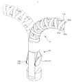
도 1은 일 실시예에 따른 암 유닛 및 구동유닛을 도시한 도면.
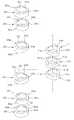
도 2는 도 1의 암 유닛을 구성하는 링크들을 도시한 도면.
도 3은 도 2를 다른 각도에서 바라본 보습을 도시한 도면.
도 4는 도 2의 측면도.
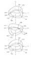
도 5a 및 도 5b는 일 실시예에 따른 암 유닛의 틸트(Tilt) 모션과 팬(Pan) 모션을 도시한 도면.
도 6a, 도 6b, 도 6c, 도 7a, 도 7b는 와이어에 가해지는 장력과 암 유닛의 강성 간의 관계를 설명하기 위한 도면.
도 8a, 도 8b, 도 8c는 일 실시예에 따른 암 유닛을 구성하는 링크들 사이에 미끄럼방지부재가 삽입되는 모습을 도시한 도면.
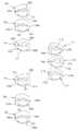
도 9a, 도 9b, 도 9c는 다른 일 실시예에 따른 암 유닛을 도시한 도면.
도 10a, 도 10b, 도 10c는 또 다른 일 실시예에 따른 암 유닛을 도시한 도면.
도 11a, 도 11b, 도 11c는 또 다른 일 실시예에 따른 암 유닛을 도시한 도면.1 is a view showing an arm unit and a drive unit according to an embodiment.
FIG. 2 is a view showing links forming the arm unit of FIG. 1. FIG.
FIG. 3 is a view illustrating moisturizing viewed from another angle of FIG. 2. FIG.
Figure 4 is a side view of Figure 2;
5A and 5B illustrate a tilt motion and a pan motion of an arm unit according to one embodiment.
6A, 6B, 6C, 7A, and 7B are views for explaining the relationship between the tension applied to the wire and the rigidity of the arm unit.
8A, 8B, and 8C are views illustrating a non-slip member inserted between links constituting an arm unit according to an exemplary embodiment.
9A, 9B and 9C illustrate arm units according to another embodiment.
10A, 10B and 10C show arm units according to yet another embodiment.
11A, 11B, and 11C illustrate arm units according to yet another embodiment.
이하에서는 실시예를 첨부된 도면을 참조하여 상세히 설명한다.Hereinafter, exemplary embodiments will be described in detail with reference to the accompanying drawings.
도 1은 일 실시예에 따른 암 유닛 및 구동유닛을 도시한 도면이다.1 is a view showing an arm unit and a drive unit according to an embodiment.
도 1에 도시된 바와 같이, 로봇(1)은 암 유닛(10)과, 암 유닛(10)을 구동하기 위한 구동유닛(50)을 포함하여 구성된다.As shown in FIG. 1, the
암 유닛(10)은 일렬(Serial)로 배치되고 서로 구름 접촉(rolling contact)하는 링크들(110)과, 링크들(110)을 관통하여 연결하는 와이어들(181a, 181b, 182a, 182b)을 포함한다.The
와이어들(181a, 181b, 182a, 182b)은 암 유닛(10)의 틸트 모션을 구현하기 위해 대향하여 배치되는 한 쌍의 제1와이어(181a, 181b)와, 암 유닛(10)의 팬 모션을 구현하기 위해 대향하여 배치되는 한 쌍의 제2와이어(182a, 182b)를 포함한다.The
구동유닛(50)은 와이어들(181a, 181b, 182a, 182b)의 경로를 변경하는 적어도 하나의 풀리(52)와, 와이어들(181a, 181b, 182a, 182b)에 가해지는 장력을 조절할 수 있도록 와이어들(181a, 181b, 182a, 182b)과 연결되는 구동 플레이트(54)와, 구동 플레이트(54)를 구동하기 위한 구동모터(미도시)를 포함한다.The driving
구동 플레이트(54)는 와이어들(181a, 181b, 182a, 182b)이 감길 수 있도록 원호 형상으로 마련될 수 있고, 암 유닛(10)의 틸트 모션과 관계되는 제1와이어(181a, 181b)와 연결되어 제1와이어(181a, 181b)의 장력을 조절하는 제1구동 플레이트(54a)와, 암 유닛(10)의 팬 모션과 관계되는 제2와이어(182a, 182b)와 연결되어 제2와이어(182a, 182b)의 장력을 조절하는 제2구동 플레이트(54b)를 포함한다.The driving
제1구동 플레이트(54a)와 제2구동 플레이트(54b)는 각각 개별적으로 구동되어 회전하면서 암 유닛(10)의 틸트 모션과 팬 모션을 구현하기 위한 제1와이어(181a, 181b) 및 제2와이어(182a, 182b)의 장력을 조절할 수 있다.The
도 2는 도 1의 암 유닛을 구성하는 링크들을 도시한 도면이고, 도 3은 도 2를 다른 각도에서 바라본 보습을 도시한 도면이며, 도 4는 도 2의 측면도이고, 도 5a 및 도 5b는 일 실시예에 따른 암 유닛의 틸트(Tilt) 모션과 팬(Pan) 모션을 도시한 도면이다.FIG. 2 is a view illustrating links constituting the arm unit of FIG. 1, FIG. 3 is a view illustrating moisturizing viewed from different angles of FIG. 2, FIG. 4 is a side view of FIG. 2, and FIGS. 5A and 5B are FIG. 1 is a diagram illustrating a tilt motion and a pan motion of an arm unit, according to an exemplary embodiment.
도 2 내지 도 5b에 도시된 바와 같이, 링크(110)는 그 중심부가 중공된 형상의 몸체(112)와, 링크(110)의 상부에 이웃하여 배치되는 다른 링크(110)를 향하는 제1방향으로 몸체(112)가 굴곡되어 형성되는 한 쌍의 제1구름 접촉부(114a, 114b)와, 제1방향과 반대되는 방향으로 몸체(112)가 굴곡되어 형성되는 한 쌍의 제2구름 접촉부(116a, 116b)를 포함한다.As shown in FIGS. 2 to 5B, the
제1구름 접촉부(114a, 114b)는 그 상부에 이웃하는 다른 링크(110)와 접촉할 수 있도록 몸체(112) 상부면의 일부 구간이 몸체(112)의 길이 방향으로 돌출 형성되고, 제2구름 접촉부(116a, 116b)는 그 하부에 이웃하는 다른 링크(110)와 접촉할 수 있도록 몸체(112) 하부면의 일부 구간이 제1구름 접촉부(114a, 114b)가 돌출되는 방향과 반대되는 방향으로 돌출 형성되므로, 제1구름 접촉부(114a, 114b) 및 제2구름 접촉부(116a, 116b)를 각각 제1볼록부(114a, 114b) 및 제2볼록부(116a, 116b)로 볼 수 있다.Some sections of the upper surface of the
한 쌍의 제1구름 접촉부(114a, 114b) 및 한 쌍의 제2구름 접촉부(116a, 116b)는 몸체(112)가 연장되는 방향을 따라 몸체(112)의 중심을 관통하는 중심선(Lc)을 기준으로 180°회전된 위치에 서로 배치되고, 한 쌍의 제1구름 접촉부(114a, 114b)는 중심선(Lc)을 기준으로 몸체(112)의 원주 방향을 따라 제2구름 접촉부(116a, 116b)와 각각 90°회전된 위치에 배치된다.The pair of
제1구름 접촉부(114a, 114b)가 형성되는 몸체(112) 상부면에는 제1구름 접촉부(114a, 114b)와 연결되는 제1오목부(115a, 115b)가 형성되고, 제2구름 접촉부(116a, 116b)가 형성되는 몸체(112) 하부면에는 제2구름 접촉부(116a, 116b)와 연결되는 제2오목부(117a, 117b)가 형성된다. 제1오목부(115a, 115b)는 중심선(Lc)을 기준으로 몸체(112)의 원주 방향을 따라 제1구름 접촉부(114a, 114b)와 각각 90°회전된 위치에 배치되고, 제2오목부(117a, 117b)는 중심선(Lc)을 기준으로 몸체(112)의 원주 방향을 따라 제2구름 접촉부(116a, 116b)와 각각 90°회전된 위치에 배치된다. 제1구름 접촉부(114a, 114b)는 중심선(Lc)을 포함하는 가상의 제1분할면(F1)을 기준으로 서로 대칭되는 위치에 배치되고, 제1오목부(115a, 115b)는 중심선(Lc)을 포함하며 제1분할면(F1)과 직교하는 가상의 제2분할면(F2)을 기준으로 서로 대칭되는 위치에 배치된다.First
한 쌍의 제1구름 접촉부(114a, 114b) 및 한 쌍의 제2구름 접촉부(116a, 116b)에는 틸트 모현 및 팬 모션을 구현하기 위한 제1와이어(181a, 181b) 및 제2와이어(182a, 182b)가 관통하는 제1관통홀(121a, 121b) 및 제2관통홀(122a, 122b)이 마련된다.The pair of
각각의 개별 링크(110)는 서로 이웃하는 다른 개별 링크(110)들과 중심선(Lc)을 기준으로 90°회전된 상태로 순차적으로 결합되어 암 유닛(10)을 구성한다. 따라서 도 1에 보여지는 바와 같이, 제1와이어(181a, 181b) 및 제2와이어(182a, 182b) 각각은 링크(110)의 제1관통홀(121a, 121b) 및 이웃하는 링크(110)의 제2관통홀(122a, 122b)을 관통한다.Each
이웃하는 개별 링크들(110)이 서로 상대 회전할 수 있도록 제1구름 접촉부(114a, 114b) 및 한 쌍의 제2구름 접촉부(116a, 116b)의 적어도 일 부분은 도 4에 도시된 바와 같이 소정의 곡률을 가지는 원(C)의 일부를 포함할 수 있다.At least a portion of the
와이어(181a, 181b, 182a, 182b)에 힘이 가해지지 않은 상태에서, 어느 하나의 개별 링크(110)의 몸체(112) 상부면에 형성되는 제1구름 접촉부(114a, 114b)는 그 상부에 배치되는 다른 개별 링크(110)의 몸체(112) 하부면에 형성되는 제2구름 접촉부(116a, 116b)와 구름 접촉하고, 어느 하나의 개별 링크(110)의 몸체(112) 하부면에 형성되는 제2구름 접촉부(116a, 116b)는 그 하부에 배치되는 다른 개별 링크(110)의 몸체(112) 상부면에 형성되는 제1구름 접촉부(114a, 114b)와 각각 구름 접촉한다.In a state where no force is applied to the
또한, 어느 하나의 개별 링크(110)의 제1구름 접촉부(114a, 114b)와 연결되는 제1오목부(115a, 115b)는 그 상부에 배치되는 다른 개별 링크(110)의 제2구름 접촉부(116a, 116b)와 연결되는 제2오목부(117a, 117b)와 서로 대향하도록 배치되어 서로 이웃하는 개별 링크(110) 간의 상대 회동이 가능하도록 회동 공간(S1, S2)을 형성하고, 어느 하나의 개별 링크(110)의 제2구름 접촉부(116a, 116b)와 연결되는 제2오목부(117a, 117b)는 그 하부에 배치되는 다른 개별 링크(110)의 제1구름 접촉부(114a, 114b)와 연결되는 제1오목부(115a, 115b)와 서로 대향하도록 배치되어 회동 공간(S1, S2)를 형성한다.In addition, the first
도 5a에 도시된 바와 같이, 제1와이어(181a, 181b)의 장력을 조절하면, 어느 하나의 개별 링크(110)의 몸체(112) 하부면에 형성되는 제2구름 접촉부(116a, 116b)와, 그 하부에 배치되는 다른 개별 링크(110)의 몸체(112) 상부면에 형성되는 제1구름 접촉부(114a, 114b)간의 상대 회동이 발생하여 틸트(Tilt) 모션이 구현된다.As shown in FIG. 5A, when the tension of the
또한, 도 5b에 도시된 바와 같이, 제2와이어(182a, 182b)의 장력을 조절하면, 어느 하나의 개별 링크(110)의 몸체(112) 상부면에 형성되는 제1구름 접촉부(114a, 114b)와, 그 상부에 배치되는 다른 개별 링크(110)의 몸체(112) 하부면에 형성되는 제2구름 접촉부(116a, 116b)간의 상대 회동이 발생하여 팬(Pan) 모션이 구현된다.In addition, as shown in FIG. 5B, when the tension of the
이와 같이, 암 유닛(10)이 틸트 모션을 수행하는 과정에서 제1와이어(181a, 181b) 중 어느 하나가 늘어나는 길이는 다른 하나가 줄어드는 길이와 다르며(Non-symmetric), 암 유닛(10)이 팬(Pan) 모션을 수행하는 과정에서 제2와이어(182a, 182b) 중 어느 하나가 늘어나는 길이는 다른 하나가 줄어드는 길이와 다르게 되며, 따라서 제1와이어(181a, 181b) 및 제2와이어(182a, 182b)에 가해지는 장력은 복수의 링크들(100)로 구성되는 암 유닛(10)의 강성과 비례 관계에 있게 된다.As such, the length in which one of the
도 6a, 도 6b, 도 7a, 도 7b는 와이어에 가해지는 장력과 암 유닛의 강성 간의 관계를 설명하기 위한 도면이다.6A, 6B, 7A, and 7B are views for explaining the relationship between the tension applied to the wire and the rigidity of the arm unit.
여기서 'n'은 개별 링크(110)의 개수를 나타내고, 'Φp'및'Φt'는 팬 모션 및 틸트 모션 각각에서 이웃하는 개별 링크(110) 간에 형성되는 각도를 나타내며,'θp'및'θt'는 팬 모션 및 틸트 모션 각각에서 끝단에 위치한 개별 링크(110)가 형성하는 각도를 의미하며, 'Lpl' 및'Lpr'은 각각 이웃하는 개별 링크(110)를 연결하는 제2와이어(182a, 182b)의 일부분의 길이를 의미하고, 'dpl' 및'dpr'은 제2와이어(182a, 182b)의 전체 길이를 의미한다.Here, 'n' represents the number of
도 6a, 도 6b를 참고하여, 제2와이어(182a, 182b)의 늘어나거나 줄어든 길이를 위의 변수들 간의 관계를 이용하여 유도해보면 다음과 같다.Referring to FIGS. 6A and 6B, the lengths of the

이 때, 'dpl(θp,θt)'와 'dpr(θp,θt)'의 합은 '0(zero)'이 아니다. 즉, 암 유닛(10)이 틸트 모션 또는 팬 모션을 수행하는 과정에서 제2와이어(182a, 182b)중 어느 하나(182a)가 늘어난 길이와 다른 하나(182b)가 줄어든 길이의 절대값은 서로 다르다. 이는 제1와이어(181a, 181b)에도 동일하게 적용된다.At this time, the sum of 'dpl (θp ,θt )' and 'dpr (θp ,θt )' is not '0 (zero)'. That is, the absolute value of the length in which one of the
이와 같이, 암 유닛(10)이 틸트 모션 또는 팬 모션을 수행하는 과정에서 제1와이어(181a, 181b) 및 제2와이어(182a, 182b)의 비대칭성(Non-symmetric)으로 인해 제1와이어(181a, 181b) 및 제2와이어(182a, 182b)의 장력(Tension) 조절을 통해 암 유닛(10)의 강성(Stiffness)을 변경시킬 수 있다.As described above, in the process of the
도 7a, 도 7b를 참고하여 제1와이어(181a, 181b) 및 제2와이어(182a, 182b)에 가해지는 장력(T)과 암 유닛(10)의 강성(K)간의 관계를 유도해보면 다음과 같다.Referring to FIGS. 7A and 7B, the relationship between the tension T applied to the

여기서 도 7b에 도시된 바와 같이, 가상일의 원리(Virtual work concept)을 적용하면, 다음과 같다.As shown in FIG. 7B, the virtual work concept is applied as follows.

위의 식들을 정리해보면,To sum up the above expressions,

위의 식에서 알 수 있듯이, 제1와이어(181a, 181b) 및 제2와이어(182a, 182b)에 가해지는 장력(T)과 암 유닛(10)의 강성(K)은 서로 비례 관계에 있으며, 따라서 제1와이어(181a, 181b) 및 제2와이어(182a, 182b)의 장력(T)을 조절하여 암 유닛(10)의 강성(Stiffness)을 변경시킬 수 있다.As can be seen from the above equation, the tension T applied to the
이와 같은 구조를 통해, 암 유닛(10)이 굴곡이 있는 환자의 내부 또는 장기를 따라 수술부위까지 이동하는 동안에는 암 유닛(10)의 강성을 줄여 유연성을 가지도록 하고, 수술부위에 도달하여 수술을 수행하는 과정에서는 암 유닛(10) 가해지는 하중을 견딜 수 있도록 강성을 높여 유연성을 가지지 않도록 함으로써 좀 더 효율적으로 수술을 수행할 수 있다.Through this structure, while the
도 8a 내지 도 8c는 일 실시예에 따른 암 유닛을 구성하는 링크들 사이에 미끄럼방지부재가 삽입되는 모습을 도시한 도면이다.8A to 8C are views illustrating a non-slip member inserted between links constituting an arm unit according to an exemplary embodiment.
도 8a 내지 도 8c에 도시된 바와 같이, 미끄럼방지부재(150)는 서로 이웃하는 개별 링크들(110) 사이에 위치하여 개별 링크들(110)이 회동하는 과정에서 발생할 수 있는 미끄럼(Slip)을 방지한다.As shown in FIGS. 8A to 8C, the
미끄럼방지부재(150)는 그 일면(150a)과 타면(150b)를 통해 이웃하는 개별 링크들(110)과 모두 접할 수 있도록 개별 링크(110)의 몸체(112) 상부면의 일부 및 하부면의 일부가 조합된 형상으로 마련된다. 미끄럼방지부재(150)는 개별 링크(110)들과 다른 재질로 마련될 수 있으며, 특히, 미끄럼 방지에 효과적인 고무 재질이나 플라스틱 재질로 마련될 수 있다.The
도 9a 내지 도 9c는 다른 일 실시예에 따른 암 유닛을 도시한 도면이다.9A to 9C are diagrams illustrating an arm unit according to another exemplary embodiment.
암 유닛(20)을 구성하는 개별 링크들(210)의 치형부(214, 216)를 제외한 나머지 부분 및 구동 원리는 암 유닛(10)을 구성하는 개별 링크들(110)과 동일하므로 설명을 생략한다.Except for the
도 9a 내지 도 9c에 도시된 바와 같이, 암 유닛(20)의 개별 링크들(210)은 개별 링크들(210)이 서로 상대 회동하는 과정에서 발생할 수 있는 미끄럼(Slip)을 방지하기 위한 치형부(214, 216)를 더 포함한다.As shown in FIGS. 9A to 9C, the
치형부(212, 214)는 굴곡 형성되는 링크(210)의 몸체(212) 상부면에 형성되는 제1치형부(214)와, 하부면에 형성되는 제2치형부(216)을 포함한다.The
제1치형부(214) 및 제2치형부(216)는 각각 몸체(212) 상부면 및 하부면의 원주 방향을 따라 형성된다.The
복수의 링크들(210) 중 어느 하나의 개별 링크(210)에 형성되는 제1치형부(214)와 어느 하나의 개별 링크(210)의 상부에 배치되는 다른 하나의 개별 링크(210)에 형성되는 제2치형부(216)가 서로 맞물리므로, 이웃하는 개별 링크들(110)이 구름 접촉하여 상대 회동하는 과정에서 미끄럼 현상이 미연에 방지된다.The
도 10a 내지 도 10c는 또 다른 일 실시예에 따른 암 유닛을 도시한 도면이다.10A to 10C are diagrams illustrating arm units according to yet another exemplary embodiment.
도 10a 내지 도 10c에 도시한 바와 같이, 또 다른 일 실시예에 따른 암 유닛(30)은 제1링크(310)와, 제2링크(320)와, 제3링크(330)를 포함한다. 제2링크(320)는 제1링크(310)의 상면(312a)과 이웃하여 구름 접촉하는 링크이고, 제3링크(330)는 제2링크(320)의 상면(322a)과 이웃하여 면 접촉하는 링크일 수 있다.As shown in FIGS. 10A to 10C, the
위의 설명에서는 제2링크(320) 및 제3링크(330)를 각각 제1링크(310)의 상면(312a) 및 제2링크(320)의 상면(322a)과 이웃하는 것으로 설명하였으나, 제2링크(320) 및 제3링크(330)가 각각 제1링크(310)의 하면(312b) 및 제2링크(320)의 하면(322b)에도 이웃할 수 있음은 자명하다.In the above description, the
제1링크(310)는 앞서 설명한 암 유닛(10)의 개별 링크(110)와 동일하므로 자세한 설명은 생략한다.Since the
제3링크(330)는 그 중심부가 중공된 형상의 몸체(332)와, 몸체(332)의 상면(332a) 및 하면(332b)에 각각 형성되어 이웃하는 제2링크(320) 또는 제3링크(330)와 면 접촉하는 제1평탄부(334a, 334b) 및 제2평탄부(336a, 336b)를 포함한다.The
제2링크(320)는 제1링크(310)와 제3링크(330) 사이에 배치되어 제1링크(310)와 제3링크(330)를 연결하며, 그 중심부가 중공된 형상의 몸체(322)와, 몸체(322)의 제1면(322a)에 형성되는 제3평탄부(324a, 324b)와, 제1면(322a)과 반대되는 제2면(322b)에 형성되는 제3구름 접촉부(326a, 326b)를 포함한다.The
제3평탄부(324a, 324b)는 제3링크(330)에 형성되는 제1평탄부(334a, 334b) 또는 제2평탄부(336a, 336b)의 형상과 실질적으로 동일하며, 제3구름 접촉부(326a, 326b)는 제1링크(310)에 형성되는 제1구름 접촉부(314a, 314b) 또는 제2구름 접촉부(316a, 316b)의 형상과 실질적으로 동일하다.The third
제1링크들(310)은 적어도 둘 이상이 서로 이웃하도록 배치되어 상대 회동 하면서 암 유닛(30)이 틸트 모션 및 팬 모션을 취할 수 있도록 하고, 제3링크들(330)은 적어도 둘 이상이 서로 이웃하도록 배치되어 암 유닛(30)이 틸트 모션 및 팬 모션을 취하는 과정에서 실질적으로 강체(Rigid body)를 형성하도록 한다. 도 10c에 도시된 바와 같이, 제1링크들(310), 제2링크들(320), 제3링크들(330)을 연결하는 와이어들(380a, 380b)에 장력이 가해지면, 제3링크들(330)은 강체(Rigid body)를 형성하여 암 유닛(30)의 강성이 유지되도록 하고, 제1링크들(310)은 서로 상대 회전 하면서 암 유닛(30)이 틸트 모션 및 팬 모션을 취할 수 있도록 한다.The
도 11a 내지 도 11c는 또 다른 일 실시예에 따른 암 유닛을 도시한 도면이다.11A to 11C are diagrams illustrating an arm unit according to another exemplary embodiment.
도 11a 내지 도 11c에 도시한 바와 같이, 암 유닛(40)은 그 상부와 하부가 서로 대칭 형상으로 마련되는 제1링크(410)와, 그 상부와 하부가 서로 비대칭 형상으로 마련되는 제2링크(420)를 포함하여 구성된다.As illustrated in FIGS. 11A to 11C, the
제1링크(410)는 앞서 설명한 암 유닛(10)의 개별 링크(110)와 동일하므로 자세한 설명은 생략한다.Since the
제2링크(420)는 그 중심부가 중공된 형상의 몸체(422)와, 몸체(422)의 제1면(422a)에 형성되는 제4구름 접촉부(424a, 424b)와, 제1면(422a)과 반대되는 제2면(422b)에 형성되는 제5구름 접촉부(426a, 426b)를 포함한다.The
몸체(422)는 암 유닛(40)이 틸트 모션 또는 팬 모션을 수행하는 과정에서 제1링크(410) 또는 제2링크(420)가 회동 하는 방향으로 그 일측이 다른 일측에 비해 더욱 연장되므로 비대칭 형상을 가지게 되고, 따라서 제4구름 접촉부(424a, 424b) 간의 높이 차이가 발생하게 된다.The
제1링크(410)와 제2링크(420)는 서로 90°각도로 회전하여 교대로 배치되므로, 암 유닛(40)의 초기 형상이 틸트 모션 또는 팬 모션을 수행하고 있는 상태로 기울어져 배치되고, 따라서 암 유닛(40)이 더욱 큰 각도로 틸트 모션 또는 팬 모션을 수행할 수 있어, 암 유닛(40)이 수술 부위 등에 도달할 수 있는 범위가 증가하게 된다.Since the
1 : 로봇10, 20, 30, 40 : 암 유닛
50 : 구동유닛110, 210: 링크
310, 410 : 제1링크320, 420 : 제2링크
330 : 제3링크1:
50:
310, 410:
330: third link
Claims (30)
Translated fromKorean상기 암 유닛을 구동하기 위한 구동유닛;을 포함하고,
상기 암 유닛은,
적어도 둘 이상의 영역으로 서로 구름 접촉(rolling contact)하는 복수의 링크;와,
상기 복수의 링크를 관통 연결하는 복수의 와이어;
를 포함하는 기구.An arm unit;
And a driving unit for driving the arm unit.
The arm unit,
A plurality of links rolling contact each other to at least two regions; and
A plurality of wires connecting through the plurality of links;
.
상기 복수의 링크는 일렬로(serial) 배치되고, 상기 복수의 링크 중 적어도 두 개의 링크는 서로 이웃하는 다른 링크와 구름 접촉하는 기구.The method of claim 1,
And the plurality of links are arranged in series, wherein at least two of the plurality of links are in cloud contact with other links adjacent to each other.
상기 복수의 링크 중 적어도 하나의 링크는 그 중심부가 중공된 형상의 몸체인 기구.3. The method of claim 2,
At least one of said plurality of links is a hollow shaped body of a central portion thereof.
상기 복수의 링크는 상기 링크와 이웃하는 링크를 향하는 제1방향으로 상기 몸체가 굴곡되어 형성되는 복수의 제1구름 접촉부를 포함하는 기구.3. The method of claim 2,
And the plurality of links includes a plurality of first cloud contacts formed by bending the body in a first direction toward a link adjacent to the link.
상기 제1방향과 반대되는 제2방향으로 상기 몸체가 굴곡되어 형성되는 복수의 제2구름 접촉부를 포함하는 기구.5. The method of claim 4,
And a plurality of second cloud contact portions formed by bending the body in a second direction opposite to the first direction.
상기 복수의 제1구름 접촉부는 상기 몸체가 연장되는 방향을 따라 상기 몸체의 중심을 관통하는 중심선을 기준으로 180°회전된 위치에 배치되어 한 쌍으로 마련되는 기구.The method of claim 5,
And the plurality of first cloud contact portions are disposed at a position rotated by 180 ° with respect to a center line passing through the center of the body in a direction in which the body extends.
상기 복수의 제2구름 접촉부는 상기 몸체가 연장되는 방향을 따라 상기 몸체의 중심을 관통하는 중심선을 기준으로 180°회전된 위치에 배치되어 한 쌍으로 마련되는 기구.The method according to claim 6,
And a plurality of second cloud contact portions disposed in a position rotated by 180 ° with respect to a center line penetrating the center of the body in a direction in which the body extends.
상기 제1구름 접촉부는 상기 몸체가 연장되는 방향을 따라 상기 몸체의 중심을 관통하는 중심선을 기준으로 상기 제2구름 접촉부와 90°회전된 위치에 배치되는 기구.The method of claim 7, wherein
And the first cloud contact portion is disposed at a position rotated 90 ° with the second cloud contact portion with respect to a center line passing through the center of the body in a direction in which the body extends.
상기 제1구름 접촉부의 일 부분은 일정한 곡률을 가지는 원의 일부인 기구.The method of claim 3,
Wherein a portion of the first cloud contact is part of a circle having a constant curvature.
상기 복수의 링크는,
제1링크와,
상기 몸체가 연장되는 방향을 따라 상기 링크의 중심을 관통하는 중심선을 기준으로 상기 제1링크와 90°회전된 위치에서 상기 제1링크의 상부 또는 하부와 구름 접촉하는 제2링크를 포함하는 기구.3. The method of claim 2,
The plurality of links,
The first link,
And a second link in cloud contact with the top or bottom of the first link at a position rotated 90 [deg.] With the first link relative to a centerline penetrating the center of the link along a direction in which the body extends.
상기 제1링크와 상기 제2링크 사이에 위치하여 상기 제1링크와 상기 제2링크 간의 미끄럼(slip)을 방지하는 미끄럼방지부재를 더 포함하는 기구.The method of claim 10,
And a non-slip member positioned between the first link and the second link to prevent slipping between the first link and the second link.
상기 미끄럼방지부재의 일면은 상기 제1링크의 일부분과 접하고, 타면은 상기 제2링크의 일부분과 접하는 기구.12. The method of claim 11,
One surface of the non-slip member in contact with a portion of the first link, the other surface in contact with a portion of the second link.
상기 제2링크와 대향하는 상기 제1링크의 제1면과 상기 제1면과 구름 접촉하는 상기 제2링크의 제2면에는 각각 상기 제1링크와 상기 제2링크 간의 미끄럼(slip)을 방지하기 위해 서로 맞물리는 제1치형부 및 제2치형부가 마련되는 기구.The method of claim 10,
The first surface of the first link facing the second link and the second surface of the second link in contact with the first surface prevent slip between the first link and the second link, respectively. And a first tooth portion and a second tooth portion engaged with each other for the purpose of engagement.
상기 제1치형부는 그 중심부가 중공된 형상으로 마련되는 상기 제1링크의 원주방향을 따라 상기 제1면에 형성되고,
상기 제2치형부는 그 중심부가 중공된 형상으로 마련되는 상기 제2링크의 원주방향을 따라 상기 제2면에 형성되는 기구.The method of claim 13,
The first tooth portion is formed on the first surface along the circumferential direction of the first link, the central portion of which is provided in a hollow shape,
And the second tooth portion is formed on the second surface along the circumferential direction of the second link having a central portion thereof in a hollow shape.
상기 제1구름 접촉부의 높이는 서로 다른 기구.The method of claim 5,
The height of the first cloud contact is different.
상기 복수의 링크는,
그 상면과 하면이 이웃하는 다른 링크와 모두 구름 접촉하는 제1링크와,
그 상면과 하면 중 어느 하나의 면은 이웃하는 다른 링크와 구름 접촉하고, 다른 하나의 면은 이웃하는 다른 링크와 면 접촉하는 제2링크와,
그 상면과 하면이 이웃하는 다른 링크와 모두 면 접촉하는 제3링크를 포함하는 기구.3. The method of claim 2,
The plurality of links,
A first link whose upper and lower surfaces are in cloud contact with other neighboring links,
A second link of one of the upper and lower surfaces in cloud contact with another neighboring link, and the other of the upper and lower surfaces in contact with another neighboring link;
And a third link having a top surface and a bottom surface in surface contact with another neighboring link.
상기 제2링크는 상기 제1링크와 상기 제3링크 사이에 배치되는 기구.17. The method of claim 16,
The second link is disposed between the first link and the third link.
상기 제3링크는 적어도 둘 이상이 서로 이웃하도록 배치되어 상기 암 유닛이 구동되는 과정에서 강체(rigid body)를 형성하는 기구.18. The method of claim 17,
And the third link is arranged such that at least two or more are adjacent to each other to form a rigid body in the process of driving the arm unit.
상기 복수의 와이어는,
상기 제1구름 접촉부를 상기 복수의 링크가 배치되는 방향으로 관통하는 한 쌍의 제1와이어와,
상기 제2구름 접촉부를 상기 복수의 링크가 배치되는 방향으로 관통하는 한 쌍의 제2와이어를 포함하는 기구.The method of claim 7, wherein
The plurality of wires,
A pair of first wires penetrating the first cloud contact portion in a direction in which the plurality of links are arranged;
And a pair of second wires penetrating said second cloud contact portion in a direction in which said plurality of links are disposed.
상기 암 유닛이 구동되는 과정에서 상기 한 쌍의 제1와이어 중 어느 하나가 늘어나는 길이는 다른 하나가 줄어드는 길이와 다른(non-symmetric) 것을 특징으로 하는 로봇.20. The method of claim 19,
The length of which one of the pair of first wires stretches while the arm unit is driven is different from the length of which the other decreases (non-symmetric).
상기 구동유닛은,
상기 제1와이어 및 상기 제2와이어의 경로를 변경하는 적어도 하나의 풀리와,
상기 제1와이어 및 상기 제2와이어에 가해지는 장력을 조절할 수 있도록 상기 제1와이어 및 상기 제2와이어와 연결되는 구동 플레이트를 포함하는 기구.The method of claim 1,
The driving unit includes:
At least one pulley for changing a path of the first wire and the second wire,
And a drive plate connected with the first wire and the second wire to adjust the tension applied to the first wire and the second wire.
상기 링크는,
그 중심부가 중공된 형상인 몸체;와,
상기 몸체 상부면 및 하부면 중 적어도 하나의 일부 구간이 상기 몸체의 길이 방향으로 돌출 형성되어 상기 링크와 이웃하는 다른 링크와 구름 접촉하는 적어도 하나의 볼록부;를
포함하는 기구.In the mechanism comprising a arm unit including a plurality of links, and a drive unit for driving the arm unit,
The link,
A body having a hollow central shape; and
At least one convex portion of at least one of the upper and lower surfaces of the body protruding in the longitudinal direction of the body to make a cloud contact with another link adjacent to the link;
Appliances included.
상기 링크는, 상기 볼록부와 연결되는 적어도 하나의 오목부를 포함하고,
상기 오목부는 상기 링크 및 상기 링크와 이웃하는 다른 링크가 상기 볼록부를 통해 상대 회동할 수 있도록 회동 공간을 형성하는 기구.The method of claim 22,
The link includes at least one concave portion connected with the convex portion,
And the concave portion forms a rotation space such that the link and another link neighboring the link can rotate relative to each other through the convex portion.
상기 볼록부는 상기 몸체의 중심을 관통하는 중심선을 포함하는 가상의 제1분할면을 기준으로 서로 대향하는 위치에 배치되어 한 쌍으로 마련되는 기구.24. The method of claim 23,
And the convex portions are arranged in pairs at positions opposite to each other based on a first virtual divided surface including a center line passing through the center of the body.
상기 오목부는 상기 제1분할면과 직교하는 가상의 제2분할면을 기준으로 서로 대향하는 위치에 배치되어 한 쌍으로 마련되는 기구.25. The method of claim 24,
And the recesses are provided in pairs and are disposed at positions facing each other with respect to the virtual second divided surface orthogonal to the first divided surface.
상기 복수의 링크는 제1링크와, 상기 제1링크와 동일한 형상을 가지며, 상기 제1링크의 상부면 및 하부면과 이웃하는 제2링크 및 제3링크를 포함하고,
상기 제1링크는, 그 중심부가 중공된 형상의 몸체와, 상기 몸체 상부면의 일부 구간이 상기 몸체의 길이 방향으로 돌출 형성되어 상기 제2링크 와 구름 접촉하는 한 쌍의 제1볼록부와, 상기 몸체 하부면의 일부 구간이 상기 제1볼록부가 돌출되는 방향과 반대되는 방향으로 돌출 형성되어 상기 제3링크와 구름 접촉하는 한 쌍의 제2볼록부를 포함하고,
상기 제2볼록부는 상기 몸체가 연장되는 방향을 따라 상기 몸체의 중심을 관통하는 중심선을 기준으로 상기 제1볼록부와 90°회전된 위치에 배치되는 기구.The method of claim 22,
The plurality of links may include a first link and second and third links having the same shape as the first link and neighboring the upper and lower surfaces of the first link.
The first link may include a body having a hollow central portion, a portion of the upper surface of the body protruding in the longitudinal direction of the body, and a pair of first convex portions contacting the second link in rolling contact with the second link; Some sections of the lower surface of the body protrude in a direction opposite to the direction in which the first convex portion protrudes, and includes a pair of second convex portions in cloud contact with the third link.
And the second convex portion is disposed at a position rotated 90 ° with the first convex portion with respect to a center line passing through the center of the body in a direction in which the body extends.
상기 제2링크는, 그 중심부가 중공된 형상의 몸체와, 상기 몸체 상부면의 일부 구간이 상기 몸체의 길이 방향으로 돌출 형성되어 상기 제2링크 의 상부면과 이웃하는 다른 링크와 구름 접촉하는 한 쌍의 제3볼록부와, 상기 몸체 하부면의 일부 구간이 상기 제1볼록부가 돌출되는 방향과 반대되는 방향으로 돌출 형성되어 상기 제1링크와 구름 접촉하는 한 쌍의 제4볼록부를 포함하되,
상기 한 쌍의 제4볼록부는 상기 한 쌍의 제1볼록부와 각각 구름 접촉하는 기구.The method of claim 26,
The second link, as long as the central portion of the hollow body, and a portion of the upper surface of the body protruding in the longitudinal direction of the body in contact with the other link adjacent to the upper surface of the second link in the cloud A third convex portion of the pair, and a portion of the lower surface of the body includes a pair of fourth convex portions protruding in a direction opposite to the direction in which the first convex portion protrudes, and in contact with the first link;
And the pair of fourth convex portions are in cloud contact with the pair of first convex portions, respectively.
상기 제1링크와 상기 제2링크 사이에 위치하여 상기 제1링크와 상기 제2링크 간의 미끄럼(slip)을 방지하는 미끄럼방지부재를 더 포함하고,
상기 미끄럼방지부재의 일면은 상기 제1볼록부와 접하고, 타면은 상기 제4볼록부와 접하는 기구.28. The method of claim 27,
A non-slip member positioned between the first link and the second link to prevent slippage between the first link and the second link;
One surface of the non-slip member is in contact with the first convex portion, the other surface is in contact with the fourth convex portion.
상기 제1볼록부와 상기 제4볼록부는, 상기 제1링크와 상기 제2링크 간의 미끄럼(slip)을 방지하기 위해, 상기 제1볼록부의 적어도 일부와 상기 제4볼록부의 적어도 일부가 서로 맞물릴 수 있도록 치형부를 포함하는 기구.28. The method of claim 27,
The first convex portion and the fourth convex portion may be engaged with at least a portion of the first convex portion and at least a portion of the fourth convex portion to prevent slipping between the first link and the second link. Mechanisms including teeth to allow.
상기 볼록부는,
상기 한 쌍의 볼록부가 돌출되는 길이는 서로 다른 기구.25. The method of claim 24,
The convex portion
Mechanisms different in length from which the pair of protrusions protrude.
Priority Applications (4)
| Application Number | Priority Date | Filing Date | Title |
|---|---|---|---|
| CN201310183103.1ACN103417298B (en) | 2012-05-25 | 2013-05-17 | Arm unit and the robot with the arm unit |
| JP2013107170AJP6356390B2 (en) | 2012-05-25 | 2013-05-21 | Arm unit and robot including the same |
| US13/898,888US9981392B2 (en) | 2012-05-25 | 2013-05-21 | Arm unit and robot having the same |
| EP13169235.2AEP2666434B1 (en) | 2012-05-25 | 2013-05-24 | Arm unit and robot having the same |
Applications Claiming Priority (2)
| Application Number | Priority Date | Filing Date | Title |
|---|---|---|---|
| KR1020120056374 | 2012-05-25 | ||
| KR20120056374 | 2012-05-25 |
Publications (2)
| Publication Number | Publication Date |
|---|---|
| KR20130132233Atrue KR20130132233A (en) | 2013-12-04 |
| KR102023906B1 KR102023906B1 (en) | 2019-09-24 |
Family
ID=49981188
Family Applications (1)
| Application Number | Title | Priority Date | Filing Date |
|---|---|---|---|
| KR1020120131721AActiveKR102023906B1 (en) | 2012-05-25 | 2012-11-20 | Arm unit and robot having the same |
Country Status (1)
| Country | Link |
|---|---|
| KR (1) | KR102023906B1 (en) |
Cited By (6)
| Publication number | Priority date | Publication date | Assignee | Title |
|---|---|---|---|---|
| KR20170047237A (en)* | 2014-08-25 | 2017-05-04 | 폴 에카스 | Shock absorbing and self realigning robotic fingers |
| KR20200081125A (en)* | 2018-12-27 | 2020-07-07 | 재단법인대구경북과학기술원 | Compliant joint |
| KR102128269B1 (en)* | 2019-04-09 | 2020-07-08 | 한국과학기술연구원 | Articulating structure using rolling joint and pin coupling, and Tube insert device haivng the same |
| CN112405601A (en)* | 2020-11-23 | 2021-02-26 | 长沙理工大学 | A wire-actuated joint that enables decoupling of bending motion |
| US20220313231A1 (en)* | 2021-04-05 | 2022-10-06 | Easyendo Surgical Inc. | Asymmetric rolling joint device of surgical instrument |
| KR20230172152A (en)* | 2022-06-15 | 2023-12-22 | 주식회사 로엔서지컬 | Surgical device for stiffness augmentation |
Families Citing this family (1)
| Publication number | Priority date | Publication date | Assignee | Title |
|---|---|---|---|---|
| WO2022145585A1 (en)* | 2020-12-31 | 2022-07-07 | 한국과학기술원 | Device and method for implementing dynamic tactile feedback of flexible object |
Citations (3)
| Publication number | Priority date | Publication date | Assignee | Title |
|---|---|---|---|---|
| JPH06170779A (en)* | 1992-12-02 | 1994-06-21 | Mitsubishi Heavy Ind Ltd | Direction conversion type flexible arm |
| JP2009136684A (en)* | 2001-06-29 | 2009-06-25 | Intuitive Surgical Inc | Surgical implement having tendon driving multi-disk wrist joint allowing positive location |
| KR20110036800A (en)* | 2011-02-25 | 2011-04-11 | 주식회사 이턴 | Surgical Instruments |
- 2012
- 2012-11-20KRKR1020120131721Apatent/KR102023906B1/enactiveActive
Patent Citations (3)
| Publication number | Priority date | Publication date | Assignee | Title |
|---|---|---|---|---|
| JPH06170779A (en)* | 1992-12-02 | 1994-06-21 | Mitsubishi Heavy Ind Ltd | Direction conversion type flexible arm |
| JP2009136684A (en)* | 2001-06-29 | 2009-06-25 | Intuitive Surgical Inc | Surgical implement having tendon driving multi-disk wrist joint allowing positive location |
| KR20110036800A (en)* | 2011-02-25 | 2011-04-11 | 주식회사 이턴 | Surgical Instruments |
Cited By (8)
| Publication number | Priority date | Publication date | Assignee | Title |
|---|---|---|---|---|
| KR20170047237A (en)* | 2014-08-25 | 2017-05-04 | 폴 에카스 | Shock absorbing and self realigning robotic fingers |
| KR20200081125A (en)* | 2018-12-27 | 2020-07-07 | 재단법인대구경북과학기술원 | Compliant joint |
| KR102128269B1 (en)* | 2019-04-09 | 2020-07-08 | 한국과학기술연구원 | Articulating structure using rolling joint and pin coupling, and Tube insert device haivng the same |
| US11419692B2 (en) | 2019-04-09 | 2022-08-23 | Korea Institute Of Science And Technology | Articulating structure using rolling joint and pin coupling, and tube insert device having the same |
| CN112405601A (en)* | 2020-11-23 | 2021-02-26 | 长沙理工大学 | A wire-actuated joint that enables decoupling of bending motion |
| US20220313231A1 (en)* | 2021-04-05 | 2022-10-06 | Easyendo Surgical Inc. | Asymmetric rolling joint device of surgical instrument |
| CN115153675A (en)* | 2021-04-06 | 2022-10-11 | 逸吉恩竣股粉公司 | Asymmetric rolling joint device for surgical instruments |
| KR20230172152A (en)* | 2022-06-15 | 2023-12-22 | 주식회사 로엔서지컬 | Surgical device for stiffness augmentation |
Also Published As
| Publication number | Publication date |
|---|---|
| KR102023906B1 (en) | 2019-09-24 |
Similar Documents
| Publication | Publication Date | Title |
|---|---|---|
| JP6356390B2 (en) | Arm unit and robot including the same | |
| KR102023906B1 (en) | Arm unit and robot having the same | |
| US20130281924A1 (en) | Segmented instrument shaft with antirotation features | |
| KR100911248B1 (en) | Small laparoscopic surgical instruments | |
| KR101322030B1 (en) | Instrument for Minimally Invasive Surgery Having Articulation Unit Including Spherical Parts | |
| JP6155292B2 (en) | Flexible list for surgical tools | |
| CN114916894B (en) | Bendable tube with improved elastic hinge | |
| US20110251599A1 (en) | Deflectable instrument shafts | |
| US9939053B2 (en) | Robot arm driving apparatus and robot arm having the same | |
| EP2670289B1 (en) | Articulation joints for torque transmission | |
| EP2835107A1 (en) | Minimally invasive surgical instrument having articulation immobilising structure | |
| JP2007044503A (en) | Electroactive polymer-operated gastric band | |
| US9357984B2 (en) | Constant value gap stabilizer for articulating links | |
| US20130023859A1 (en) | Articulating Links with Middle Link Control System | |
| KR20130090623A (en) | Link unit, arm module and apparatus for surgery having the same | |
| ES2921748T3 (en) | corrugated pipe | |
| US10492669B2 (en) | Bending device, control device, and medical instrument | |
| AU2006203220A1 (en) | Electroactive polymer-based flexing access port | |
| CN111407412A (en) | Natural cavity operation end manipulator | |
| KR101369515B1 (en) | Variable Stiffness Structure | |
| CN115721352A (en) | Rigidity-enhanced surgical system and control method thereof | |
| JP6302467B2 (en) | Thoracoscopic trocar and thoracoscopic port instrumentation kit | |
| KR101486645B1 (en) | Instrument for Minimally Invasive Surgery Having Variable Bending | |
| KR20150132815A (en) | Trocar | |
| KR20130131276A (en) | Instrument for minimally invasive surgery having improved articulation unit |
Legal Events
| Date | Code | Title | Description |
|---|---|---|---|
| PA0109 | Patent application | St.27 status event code:A-0-1-A10-A12-nap-PA0109 | |
| P11-X000 | Amendment of application requested | St.27 status event code:A-2-2-P10-P11-nap-X000 | |
| P13-X000 | Application amended | St.27 status event code:A-2-2-P10-P13-nap-X000 | |
| PG1501 | Laying open of application | St.27 status event code:A-1-1-Q10-Q12-nap-PG1501 | |
| A201 | Request for examination | ||
| PA0201 | Request for examination | St.27 status event code:A-1-2-D10-D11-exm-PA0201 | |
| P22-X000 | Classification modified | St.27 status event code:A-2-2-P10-P22-nap-X000 | |
| E902 | Notification of reason for refusal | ||
| PE0902 | Notice of grounds for rejection | St.27 status event code:A-1-2-D10-D21-exm-PE0902 | |
| AMND | Amendment | ||
| E13-X000 | Pre-grant limitation requested | St.27 status event code:A-2-3-E10-E13-lim-X000 | |
| P11-X000 | Amendment of application requested | St.27 status event code:A-2-2-P10-P11-nap-X000 | |
| P13-X000 | Application amended | St.27 status event code:A-2-2-P10-P13-nap-X000 | |
| R18-X000 | Changes to party contact information recorded | St.27 status event code:A-3-3-R10-R18-oth-X000 | |
| E601 | Decision to refuse application | ||
| PE0601 | Decision on rejection of patent | St.27 status event code:N-2-6-B10-B15-exm-PE0601 | |
| AMND | Amendment | ||
| E13-X000 | Pre-grant limitation requested | St.27 status event code:A-2-3-E10-E13-lim-X000 | |
| P11-X000 | Amendment of application requested | St.27 status event code:A-2-2-P10-P11-nap-X000 | |
| P13-X000 | Application amended | St.27 status event code:A-2-2-P10-P13-nap-X000 | |
| PX0901 | Re-examination | St.27 status event code:A-2-3-E10-E12-rex-PX0901 | |
| PX0701 | Decision of registration after re-examination | St.27 status event code:A-3-4-F10-F13-rex-PX0701 | |
| X701 | Decision to grant (after re-examination) | ||
| GRNT | Written decision to grant | ||
| PR0701 | Registration of establishment | St.27 status event code:A-2-4-F10-F11-exm-PR0701 | |
| PR1002 | Payment of registration fee | St.27 status event code:A-2-2-U10-U11-oth-PR1002 Fee payment year number:1 | |
| PG1601 | Publication of registration | St.27 status event code:A-4-4-Q10-Q13-nap-PG1601 | |
| PR1001 | Payment of annual fee | St.27 status event code:A-4-4-U10-U11-oth-PR1001 Fee payment year number:4 | |
| PR1001 | Payment of annual fee | St.27 status event code:A-4-4-U10-U11-oth-PR1001 Fee payment year number:5 | |
| PR1001 | Payment of annual fee | St.27 status event code:A-4-4-U10-U11-oth-PR1001 Fee payment year number:6 | |
| P22-X000 | Classification modified | St.27 status event code:A-4-4-P10-P22-nap-X000 | |
| PR1001 | Payment of annual fee | St.27 status event code:A-4-4-U10-U11-oth-PR1001 Fee payment year number:7 |