KR20130128380A - Capacitive stylus for a touch screen - Google Patents
Capacitive stylus for a touch screenDownload PDFInfo
- Publication number
- KR20130128380A KR20130128380AKR20137008132AKR20137008132AKR20130128380AKR 20130128380 AKR20130128380 AKR 20130128380AKR 20137008132 AKR20137008132 AKR 20137008132AKR 20137008132 AKR20137008132 AKR 20137008132AKR 20130128380 AKR20130128380 AKR 20130128380A
- Authority
- KR
- South Korea
- Prior art keywords
- stylus
- signal
- capacitive
- array
- sensing array
- Prior art date
- Legal status (The legal status is an assumption and is not a legal conclusion. Google has not performed a legal analysis and makes no representation as to the accuracy of the status listed.)
- Withdrawn
Links
Images


Classifications
- G—PHYSICS
- G06—COMPUTING OR CALCULATING; COUNTING
- G06F—ELECTRIC DIGITAL DATA PROCESSING
- G06F3/00—Input arrangements for transferring data to be processed into a form capable of being handled by the computer; Output arrangements for transferring data from processing unit to output unit, e.g. interface arrangements
- G06F3/01—Input arrangements or combined input and output arrangements for interaction between user and computer
- G06F3/03—Arrangements for converting the position or the displacement of a member into a coded form
- G06F3/041—Digitisers, e.g. for touch screens or touch pads, characterised by the transducing means
- G06F3/044—Digitisers, e.g. for touch screens or touch pads, characterised by the transducing means by capacitive means
- G06F3/0445—Digitisers, e.g. for touch screens or touch pads, characterised by the transducing means by capacitive means using two or more layers of sensing electrodes, e.g. using two layers of electrodes separated by a dielectric layer
- G—PHYSICS
- G06—COMPUTING OR CALCULATING; COUNTING
- G06F—ELECTRIC DIGITAL DATA PROCESSING
- G06F3/00—Input arrangements for transferring data to be processed into a form capable of being handled by the computer; Output arrangements for transferring data from processing unit to output unit, e.g. interface arrangements
- G06F3/01—Input arrangements or combined input and output arrangements for interaction between user and computer
- G06F3/03—Arrangements for converting the position or the displacement of a member into a coded form
- G06F3/033—Pointing devices displaced or positioned by the user, e.g. mice, trackballs, pens or joysticks; Accessories therefor
- G06F3/0354—Pointing devices displaced or positioned by the user, e.g. mice, trackballs, pens or joysticks; Accessories therefor with detection of 2D relative movements between the device, or an operating part thereof, and a plane or surface, e.g. 2D mice, trackballs, pens or pucks
- G06F3/03545—Pens or stylus
- G—PHYSICS
- G06—COMPUTING OR CALCULATING; COUNTING
- G06F—ELECTRIC DIGITAL DATA PROCESSING
- G06F3/00—Input arrangements for transferring data to be processed into a form capable of being handled by the computer; Output arrangements for transferring data from processing unit to output unit, e.g. interface arrangements
- G06F3/01—Input arrangements or combined input and output arrangements for interaction between user and computer
- G06F3/03—Arrangements for converting the position or the displacement of a member into a coded form
- G06F3/033—Pointing devices displaced or positioned by the user, e.g. mice, trackballs, pens or joysticks; Accessories therefor
- G06F3/038—Control and interface arrangements therefor, e.g. drivers or device-embedded control circuitry
- G06F3/0383—Signal control means within the pointing device
- G—PHYSICS
- G06—COMPUTING OR CALCULATING; COUNTING
- G06F—ELECTRIC DIGITAL DATA PROCESSING
- G06F3/00—Input arrangements for transferring data to be processed into a form capable of being handled by the computer; Output arrangements for transferring data from processing unit to output unit, e.g. interface arrangements
- G06F3/01—Input arrangements or combined input and output arrangements for interaction between user and computer
- G06F3/03—Arrangements for converting the position or the displacement of a member into a coded form
- G06F3/041—Digitisers, e.g. for touch screens or touch pads, characterised by the transducing means
- G06F3/0416—Control or interface arrangements specially adapted for digitisers
- G06F3/04162—Control or interface arrangements specially adapted for digitisers for exchanging data with external devices, e.g. smart pens, via the digitiser sensing hardware
- G—PHYSICS
- G06—COMPUTING OR CALCULATING; COUNTING
- G06F—ELECTRIC DIGITAL DATA PROCESSING
- G06F3/00—Input arrangements for transferring data to be processed into a form capable of being handled by the computer; Output arrangements for transferring data from processing unit to output unit, e.g. interface arrangements
- G06F3/01—Input arrangements or combined input and output arrangements for interaction between user and computer
- G06F3/03—Arrangements for converting the position or the displacement of a member into a coded form
- G06F3/041—Digitisers, e.g. for touch screens or touch pads, characterised by the transducing means
- G06F3/0416—Control or interface arrangements specially adapted for digitisers
- G06F3/04166—Details of scanning methods, e.g. sampling time, grouping of sub areas or time sharing with display driving
- G—PHYSICS
- G06—COMPUTING OR CALCULATING; COUNTING
- G06F—ELECTRIC DIGITAL DATA PROCESSING
- G06F3/00—Input arrangements for transferring data to be processed into a form capable of being handled by the computer; Output arrangements for transferring data from processing unit to output unit, e.g. interface arrangements
- G06F3/01—Input arrangements or combined input and output arrangements for interaction between user and computer
- G06F3/03—Arrangements for converting the position or the displacement of a member into a coded form
- G06F3/041—Digitisers, e.g. for touch screens or touch pads, characterised by the transducing means
- G06F3/044—Digitisers, e.g. for touch screens or touch pads, characterised by the transducing means by capacitive means
- G06F3/0441—Digitisers, e.g. for touch screens or touch pads, characterised by the transducing means by capacitive means using active external devices, e.g. active pens, for receiving changes in electrical potential transmitted by the digitiser, e.g. tablet driving signals
- G—PHYSICS
- G06—COMPUTING OR CALCULATING; COUNTING
- G06F—ELECTRIC DIGITAL DATA PROCESSING
- G06F3/00—Input arrangements for transferring data to be processed into a form capable of being handled by the computer; Output arrangements for transferring data from processing unit to output unit, e.g. interface arrangements
- G06F3/01—Input arrangements or combined input and output arrangements for interaction between user and computer
- G06F3/03—Arrangements for converting the position or the displacement of a member into a coded form
- G06F3/041—Digitisers, e.g. for touch screens or touch pads, characterised by the transducing means
- G06F3/044—Digitisers, e.g. for touch screens or touch pads, characterised by the transducing means by capacitive means
- G06F3/0442—Digitisers, e.g. for touch screens or touch pads, characterised by the transducing means by capacitive means using active external devices, e.g. active pens, for transmitting changes in electrical potential to be received by the digitiser
- G—PHYSICS
- G06—COMPUTING OR CALCULATING; COUNTING
- G06F—ELECTRIC DIGITAL DATA PROCESSING
- G06F3/00—Input arrangements for transferring data to be processed into a form capable of being handled by the computer; Output arrangements for transferring data from processing unit to output unit, e.g. interface arrangements
- G06F3/01—Input arrangements or combined input and output arrangements for interaction between user and computer
- G06F3/03—Arrangements for converting the position or the displacement of a member into a coded form
- G06F3/041—Digitisers, e.g. for touch screens or touch pads, characterised by the transducing means
- G06F3/044—Digitisers, e.g. for touch screens or touch pads, characterised by the transducing means by capacitive means
- G06F3/0446—Digitisers, e.g. for touch screens or touch pads, characterised by the transducing means by capacitive means using a grid-like structure of electrodes in at least two directions, e.g. using row and column electrodes
Landscapes
- Engineering & Computer Science (AREA)
- General Engineering & Computer Science (AREA)
- Theoretical Computer Science (AREA)
- Human Computer Interaction (AREA)
- Physics & Mathematics (AREA)
- General Physics & Mathematics (AREA)
- Position Input By Displaying (AREA)
Abstract
Translated fromKoreanDescription
Translated fromKorean이 출원은 2010년 9월 22일자로 출원된 미국 가출원 61/385,463을 우선권으로 주장하며, 상기 미국 가출원의 전체 내용은 이용에 의해 본원에 포함된다. 이 출원은, 함께 제출되고, 어토니 도켓 넘버 CD10080이며, "Capacitive Stylus with Palm Rejection" 라는 제목의, 번호가 아직 부여되지 않은 공동 계류 중인 미국 출원, 및 함께 제출되고, 어토니 도켓 넘버 CD10083이며, "Synchronizing Stylus with a Capacitive Sense Array" 라는 제목의, 번호가 아직 부여되지 않은 공동 계류 중인 미국 출원에 관련된다.This application claims priority to US Provisional Application 61 / 385,463, filed September 22, 2010, the entire contents of which are incorporated herein by use. This application is filed together, is Tony Docket No. CD10080, co-pending US application, yet to be numbered, entitled “Capacitive Stylus with Palm Rejection,” and submitted together, Tony Dockt No. CD10083, A co-pending U.S. application, entitled "Synchronizing Stylus with a Capacitive Sense Array," which is not yet numbered.
이 개시물은 사용자 인터페이스 디바이스들의 분야에, 그리고 특히 용량성 센서 디바이스들에 관련된다.This disclosure relates to the field of user interface devices, and in particular to capacitive sensor devices.
터치 스크린 인터페이스를 갖는 스타일러스의 사용이 잘 구축되었다. 터치 스크린 설계들은 저항성, 용량성, 유도성, 및 무선 주파수 감지 어레이들을 포함하는 상이한 기술들을 통합하였다. 저항성 터치 스크린들은 예를 들어, 패시브 스타일러스(passive stylus)와 함께 사용하기에 적절한 패시브 디바이스들이다. 1990년대 중반으로부터의 원래의 PalmPilots® 디바이스들은 스타일러스와 함께 사용하도록 설계된 저항성 터치 스크린을 이용하기 위한 첫번째 성공적인 상업적 디바이스들 중 하나였으며, 그 기술이 대중화되도록 도왔다. 저항성 터치 스크린들이 임의의 오브젝트(object) 근처로부터 입력을 감지할 수 있으나, 멀티-터치는 일반적으로 지원되지 않는다. 멀티-터치 애플리케이션의 일예는 터치 스크린에 둘 또는 그 초과의 손가락들을 적용하는 것일 수 있다. 다른 예는 서명을 입력하는 것일 수 있는데, 이는 동시적인 팜(palm) 및 스타일러스 입력 신호들을 포함할 수 있다. 이들 그리고 다른 다수의 단점들로 인하여, 용량성 터치 스크린들은 소비 시장에서 저항성 터치 스크린들을 점점 더 대체하고 있다.The use of a stylus with a touch screen interface has been well established. Touch screen designs have incorporated different technologies including resistive, capacitive, inductive, and radio frequency sensing arrays. Resistive touch screens are passive devices suitable for use with, for example, passive stylus. Original PalmPilots® devices from the mid-1990s were one of the first successful commercial devices to use resistive touch screens designed for use with a stylus, helping to make the technology popular. Resistive touch screens can sense input from near any object, but multi-touch is generally not supported. One example of a multi-touch application may be to apply two or more fingers to the touch screen. Another example may be entering a signature, which may include simultaneous palm and stylus input signals. Due to these and many other shortcomings, capacitive touch screens are increasingly replacing resistive touch screens in the consumer market.
다양한 테더링된(tethered) 액티브 스타일러스 접근법들은 터치 스크린들과 함께 사용하기 위하여 구현되었으며, 매장(point-of-sale) 단말들(예를 들어, 소매넘들에서의 신용 카드 거래들을 위해 사용되는 서명 패드) 및 다른 대중적 사용들과 같은 다수의 소비자 애플리케이션들에서 발견된다. 그러나, 개인용 컴퓨터들("PC들"), 스마트폰들, 및 태블릿 PC들과 같은 태블릿 PC들과 같은 민간 활용들을 위한 상당한 단점이다.Various tethered active stylus approaches have been implemented for use with touch screens, and a signature pad used for point-of-sale terminals (eg, credit card transactions in retail). And other popular uses. However, it is a significant drawback for private applications such as personal computers (“PCs”), smartphones, and tablet PCs such as tablet PCs.
도 1a는 유도성 감지 어레이(107) 상의 터치 오브젝트의 위치를 추적하기 위한 호스트 디바이스(100)의 종래의 실시예를 예시하는 블록도이다. 호스트 디바이스(100)는 인쇄 회로 보드("PCB")(105), 제1 매칭 회로(110), 수신기(115), 호스트 중앙 처리 장치("CPU")(120), 개인용 컴퓨터("PC")(125), 송신기(130) 및 제2 매칭 회로(135)를 포함한다. PCB(105)는 통상적으로 터치 스크린(미도시) 뒤에 배치되고, 유도성 감지 어레이(107)를 포함한다. 유도성 감지 어레이(107)는 일련의 유도성 코일들을 포함한다. 유도성 감지 어레이들은 통상적으로 제작하기에 너무 무겁고 비싸다.1A is a block diagram illustrating a conventional embodiment of a
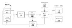
도 1b는 유도성 감지 어레이(107) 상에 터치 오브젝트의 위치를 추적하기 위한 시스템에서 사용되는 액티브 스타일러스(150)의 종래의 실시예를 예시하는 블록도이다. 스타일러스(150)는 마이크로-제어기 유닛("MCU")(155), 드라이버(160), 인덕터 이레이저(165) 인덕터 팁(170), 정류기(175), 전력 레귤레이터(180), 버튼(들)(185), 힘 팁(190) 및 힘 이레이저(195)를 포함한다. 인덕터 이레이저(165) 및 인덕터 팁(170)은 상이한 스타일러스 에지들 상에 구성된다.1B is a block diagram illustrating a conventional embodiment of an
동작 시, PCB(105) 상의 유도성 감지 어레이(107)는 스타일러스 전력 생성 및 터치 위치 검출 양자 모두를 제공하기 위하여 자기장을 발생시킨다. 터치 위치와 무관하게, 매칭 회로(110)는 임피던스 매칭을 제공하고, 유도성 감지 어레이(107)로부터의 스타일러스(150) 신호를 수신기(115)에 결합한다. 수신기(115) 및 호스트 CPU(120)는 각각 아날로그 신호를 수신하고 프로세싱하여, PC(125)에 터치 위치 및 힘 데이터를 제공한다. 힘 데이터는 터치 스크린에 대해 스타일러스 팁에 의하여 제공되는 압력의 양을 표시한다. 호스트 CPU(120)는 유도성 감지 어레이(107)의 각각의 코일의 상대적 인덕터 신호 강도에 기반하여 터치 위치를 계산한다. 더욱 상세히, 스타일러스(150)의 존재는 스타일러스로의 그들의 상대적인 근접에 기반하여 유도성 감지 어레이(107) 각각의 코일에 대한 개별적인 인덕터 전류들을 변화시킨다. 최대 신호 강도는 수반되는 터치 스크린 상의 스타일러스(150) 터치 위치에 가까워진다.In operation, the
호스트 CPU(120)는 증폭기(미도시), 송신기(130), 임피던스 매칭 회로(135) 및 유도성 감지 어레이(107)를 통해 고주파수 캐리어 신호를 스타일러스(150)에 전송한다. 스타일러스(150)는 자가-전력공급 및 데이터 송신을 위해 고주파수 캐리어 신호를 수신하고 이용한다. 동작 시, 스타일러스(150)는 캐리어 신호를 정류시키고(정류기(175)) 레귤레이팅하며(전력 레귤레이터(180)), 결과적인 신호를 MCU(155) 및 드라이버(160)로 공급한다. MCU(155)는 힘 센서들(힘 팁(190) 및 힘 이레이저(195)) 및 버튼 상태들(버튼(들)(185))을 측정하고, 결과적인 데이터 신호를 드라이버(160)에 결합한다. 드라이버(160)는 인덕터 팁(170) 및 인덕터 이레이저(165)를 구동시키며, 이는 스타일러스(150)를 유도성 감지 어레이(107)에 유도성으로 결합한다.The
스타일러스(150) 감지는 터치 스크린의 손가락-감지 능력과 대체로 독립적으로 구현된다. 상기 설명된 바와 같이, 스타일러스 추적은 유도성 감지 어레이(107)에 의해 교류 전류(AC) 신호를 발생시키는 것 및 스타일러스(150)의 팁에 AC 신호를 유도성으로 결합하는 것을 필요로 한다. 터치 스크린 뒤에 위치되는 유도성 감지 어레이(107)는 결국 스타일러스 신호를 수신하고, 호스트 CPU(120)는 유도성 감지 어레이(107)의 유도성 센서들 각각에서 수신된 스타일러스 신호들의 상대적 크기에 기반하여 스타일러스 팁(인덕터 팁(170))의 위치를 삽입한다(interpolate). 유도성 감지는 신뢰성 있을 수 있으나, 유도성 스타일러스 추적 해법들은 고전력 소모, 높은 전자기 간섭("EMI"), 높은 제조 비용들, 및 무거운 구성을 포함하는 심각한 상업적 단점들을 나타낸다. 더욱이, 독립적인 스타일러스 추적을 포함시키기 위해 현존하는 터치 센서(패시브 터치 오브젝트 센서)를 새로 장착하는 것은 유도성 감지 어레이(107)를 통합하기 위하여 부가적인 PCB(105) 층을 필요로 할 것이다.Stylus 150 sensing is generally implemented independently of the finger-sensing capabilities of the touch screen. As described above, stylus tracking requires generating an alternating current (AC) signal by
도 2a는 무선 주파수("RF") 감지 어레이 상의 터치 오브젝트의 위치를 추적하기 위한 호스트 디바이스(200)의 종래의 실시예를 예시하는 블록도이다. 호스트 디바이스(200)는 인듐-주석-산화물("ITO") 패널(205), 수신기(210), 데이터 디코더(215), 호스트 CPU(220) 및 PC(225)를 포함한다. 도 2b에서, 스타일러스(250)는 힘 센서(255), 측정기(260), 변조기(265), 증폭기(270), 스타일러스 팁(275) 및 기준 클록(280)을 포함한다. 스타일러스(250)는 통상적으로 배터리로 전원 공급된다(예시되지 않음).2A is a block diagram illustrating a conventional embodiment of a
동작 시, 스타일러스(250)는 RF 캐리어 신호를 발생시키고, 증폭하며, RF 결합을 통해 스타일러스 팁(275)으로부터 ITO 패널(205)로 결합한다. ITO 패널(205)은 안테나로서의 기능을 하며, 도 2b에 관하여 하기에 설명된 바와 같이 스타일러스(250)로부터 RF 캐리어 신호를 수신한다. 선택적 수신기(210)는 RF 캐리어 신호를 복조시키고, 터치 위치 신호를 호스트 CPU(220)에 그리고 힘 데이터 신호롤 데이터 디코더(215)에 결합한다. 데이터 디코더(215)는 힘 데이터를 추출하고, 이것을 호스트 CPU(220)에 결합한다. 호스트 CPU(220)는 ITO 패널(205)의 ITO 라인들 상에서 검출되는 RF 신호의 상대적인 최대 진폭에 기반하여 스타일러스 터치 위치를 계산한다. 호스트 CPU(220)는 힘 데이터에 기반하여 스타일러스에 인가된 힘을 추가로 결정한다. PC(225)는 호스트 CPU(220)를 제어한다.In operation,
도 2b는 RF 감지 어레이 상의 터치 오브젝트의 위치를 추적하기 위하여 시스템에서 사용되는 액티브 스타일러스의 종래의 실시예를 예시하는 블록도이다. 스타일러스(250)의 측정기(260)는 힘 센서(255) 상에 유도된 힘을 측정하고, 변조기(265)는 기준 클록(280)에 의하여 제공되는, 캐리어 주파수로 결과적인 힘 데이터를 변조시킨다. 증폭기(270)는 변조된 신호를 증폭시키고, 스타일러스 팁(275)으로부터 변조된 캐리어 주파수를 송신한다. 상기 설명된 바와 같이, 호스트(200)는 변조된 캐리어 신호를 디코딩하고, 결과를 PC(225)로 송신한다. RF 감지 어레이 해법이 비용 절약들 및 감소된 컴포넌트 카운트(count)를 제공할 수 있으나, 그들은 호스트(200) 상에 특별한 협대역 수신기들을 필요로 하고, RF 잡음 및 간섭의 대상이 된다. 그 결과, 종래의 터치 패널 해법들은 비용, 성능, 적용성 및 신뢰성에서 상당한 단점들을 가질 수 있다.2B is a block diagram illustrating a conventional embodiment of an active stylus used in a system to track the position of a touch object on an RF sensing array. The
본 발명은 제한이 아닌 예로서 첨부된 도면들의 그림들에서 예시된다.The invention is illustrated in the figures of the accompanying drawings as an example and not by way of limitation.
도 1a는 유도성 감지 어레이 상의 터치 오브젝트의 위치를 추적하기 위한 호스트 디바이스의 종래의 실시예를 예시하는 블록도이다.
도 1b는 유도성 감지 어레이 상의 스타일러스의 위치를 추적하기 위하여 시스템에서 사용되는 액티브 스타일러스의 종래의 실시예를 예시하는 블록도이다.
도 2a는 무선 주파수 감지 어레이 상의 스타일러스의 위치를 추적하기 위한 호스트 디바이스의 종래의 실시예를 예시하는 블록도이다.
도 2b는 무선 주파수 감지 어레이 상의 스타일러스의 위치를 추적하기 위하여 시스템에서 사용되는 액티브 스타일러스의 종래의 실시예를 예시하는 블록도이다.
도 3은 터치 오브젝트 및 스타일러스의 존재를 검출하기 위한 프로세싱 디바이스를 갖는 전자 시스템의 일 실시예를 예시하는 블록도이다.
도 4는 측정된 캐패시턴스들을 터치 좌표들로 변환하는 캐패시턴스 센서 및 N X M 전극 매트릭스를 포함하는 캐패시턴스 감지 어레이의 일 실시예를 예시하는 블록도이다.
도 5a는 모든-포인트들-처리가능 상호 캐패시턴스 감지 어레이를 스캔하는 방법의 일 실시예를 예시하는 도면이다.
도 5b는 모든-포인트들-처리가능 상호 캐패시턴스 감지 어레이를 스캔하는 방법의 일 실시예를 예시하는 도면이다.
도 6a는 측정된 캐패시턴스들을 터치 좌표들로 변환하는 터치 스크린 제어기 및 용량성 감지 어레이를 포함하는 시스템의 일 실시예를 예시하는 블록도이다.
도 6b는 측정된 캐패시턴스들을 터치 좌표들로 변환하는 터치 스크린 제어기, 용량성 감지 어레이 및 스타일러스를 포함하는 시스템의 일 실시예를 예시하는 블록도이다.
도 7a는 온/오프 스위치를 포함하는 스타일러스의 일 실시예를 예시하는 블록도이다.
도 7b는 스타일러스 가 사용중일 때를 검출하기 위하여 용량성 감지 엘리먼트를 포함하는 스타일러스의 일 실시예를 예시하는 블록도이다.
도 7c는 다수의 기능 능력들을 갖는 스타일러스 팁을 포함하는 스타일러스의 일 실시예를 예시하는 블록도이다.
도 8은 스타일러스의 일 실시예를 예시하는 블록도이다.
도 9는 발명의 일 실시예에 따른, 터치 오브젝트가 터치 스크린 상에 존재하지 않는 상호 캐패시턴스 터치 스크린 시스템에 대한 타이밍도이다.
도 10은 발명의 일 실시예에 따른, 터치 스크린 상에 손가락이 존재하는 상호 캐패시턴스 터치 스크린 시스템(950)에 대한 타이밍도이다.
도 11은 발명의 일 실시예에 따른, 터치 스크린 상에 스타일러스가 존재하는 상호 캐패시턴스 터치 스크린 시스템에 대한 타이밍도이다.
도 12는 발명의 일 실시예에 따른, 터치 스크린 상에 손가락 및 스타일러스가 존재하는 상호 캐패시턴스 터치 스크린 시스템에 대한 타이밍도이다.
도 13은 용량성 감지 어레이 상에 스타일러스를 검출하는 방법의 일 실시예의 흐름도이다.1A is a block diagram illustrating a conventional embodiment of a host device for tracking the position of a touch object on an inductive sensing array.
1B is a block diagram illustrating a conventional embodiment of an active stylus used in a system to track the position of the stylus on an inductive sensing array.
2A is a block diagram illustrating a conventional embodiment of a host device for tracking the position of a stylus on a radio frequency sensing array.
2B is a block diagram illustrating a conventional embodiment of an active stylus used in the system to track the position of the stylus on a radio frequency sensing array.
3 is a block diagram illustrating one embodiment of an electronic system having a processing device for detecting the presence of a touch object and a stylus.
4 is a block diagram illustrating one embodiment of a capacitance sensing array comprising a NXM electrode matrix and a capacitance sensor that converts measured capacitances into touch coordinates.
5A is a diagram illustrating one embodiment of a method for scanning an all-points-processable mutual capacitance sensing array.
5B is a diagram illustrating one embodiment of a method for scanning an all-points-processable mutual capacitance sensing array.
6A is a block diagram illustrating one embodiment of a system that includes a touch screen controller and a capacitive sense array that converts measured capacitances into touch coordinates.
6B is a block diagram illustrating one embodiment of a system that includes a touch screen controller, a capacitive sense array, and a stylus that converts measured capacitances into touch coordinates.
7A is a block diagram illustrating one embodiment of a stylus including an on / off switch.
7B is a block diagram illustrating one embodiment of a stylus including a capacitive sense element to detect when the stylus is in use.
7C is a block diagram illustrating one embodiment of a stylus including a stylus tip having multiple functional capabilities.
8 is a block diagram illustrating one embodiment of a stylus.
9 is a timing diagram for a mutual capacitance touch screen system in which no touch object is present on the touch screen, according to one embodiment of the invention.
10 is a timing diagram for a mutual capacitance touch screen system 950 with a finger present on a touch screen, according to one embodiment of the invention.
11 is a timing diagram for a mutual capacitance touch screen system in which a stylus is present on a touch screen, according to one embodiment of the invention.
12 is a timing diagram for a mutual capacitance touch screen system in which a finger and a stylus are present on the touch screen, according to one embodiment of the invention.
13 is a flow diagram of one embodiment of a method for detecting a stylus on a capacitive sense array.
스타일러스에 용량성 감지 어레이를 동기화하는 장치들 및 방법들이 설명된다. 일 실시예에서, 스타일러스는 타이밍 "마스터"로서 동작하도록 구성되고, 터치 스크린 컨트롤러는 이 스타일러스가 사용중일 때 용량성 감지 어레이의 타이밍을 스타일러스의 타이밍과 일치시키도록 조절한다. 스타일러스는 용량성 감지 어레이에 스타일러스 송신("TX") 신호를 용량성으로 결합시킨다. 터치 스크린 컨트롤러는 또한 패시브 터치 오브젝트(예를 들어, 손가락) 및 스타일러스 둘 다의 위치를 실질적으로 동시에 추적하도록 구성될 수 있다. 일 실시예에서, 스타일러스는, 이에 한정하지 않지만, 예를 들어, 스타일러스 팁 힘 데이터(stylus tip force data), 스타일러스 버튼 데이터, 스타일러스 가속도, 및 스타일러스 배터리 데이터를 포함하는 스타일러스 TX 신호로 추가적인 데이터를 변조하도록 구성된다. 실시예에서, 터치 스크린 컨트롤러는, 용량성 감지 어레이 상의 패시브 터치 오브젝트의 위치를 추적하기 위해, 용량성 감지 어레이의 열 전극들(row electrodes) 상에 TX 신호를 송신하고 그리고 용량성 감지 어레이의 행 전극들(column electrodes) 상에 결과로 도출된 RX 신호를 수신하도록 구성된다. 다른 실시예에서, 터치 스크린 컨트롤러는 전극들의 열들 및 행들 모두에 스타일러스 TX 신호를 수신하도록 구성된다. 터치 스크린 컨트롤러는 패시브 터치 오브젝트의 위치를 위치지정하고 추적하기 위한 TX & RX 신호들을 송신 및 수신하기 위해 열 전극 및 행 전극들을 상호교환가능하게 활용할 수 있다.Apparatuses and methods for synchronizing a capacitive sensing array with a stylus are described. In one embodiment, the stylus is configured to operate as a timing "master" and the touch screen controller adjusts the timing of the capacitive sensing array to match the timing of the stylus when the stylus is in use. The stylus capacitively couples the stylus transmit (“TX”) signal to the capacitive sense array. The touch screen controller may also be configured to track the position of both the passive touch object (eg, finger) and the stylus substantially simultaneously. In one embodiment, the stylus modulates additional data with a stylus TX signal that includes, but is not limited to, for example, stylus tip force data, stylus button data, stylus acceleration, and stylus battery data. It is configured to. In an embodiment, the touch screen controller transmits a TX signal on the row electrodes of the capacitive sense array and tracks the row of the capacitive sense array to track the position of the passive touch object on the capacitive sense array. And receive the resulting RX signal on the columns of electrodes. In another embodiment, the touch screen controller is configured to receive the stylus TX signal in both columns and rows of electrodes. The touch screen controller may interchangeably utilize column electrodes and row electrodes to transmit and receive TX & RX signals for positioning and tracking the passive touch object.
이하의 설명에서, 설명의 목적으로, 수많은 특정 세부사항들이 본 발명의 완전한 이해를 제공하기 위해 기술된다. 그러나, 이러한 구체적인 세부사항들 없이도 본 발명이 실행될 수 있다는 것은 당업자에게 명백할 것이다. 다른 예들에서, 잘-알려진 회로들, 구조들, 및 기술들은, 이 세부사항의 이해를 불필요하게 모호하게 하는 것을 회피하기 위해, 상세하게 나타내지 않지만, 블록도로 나타낸다.In the following description, for purposes of explanation, numerous specific details are set forth in order to provide a thorough understanding of the present invention. However, it will be apparent to those skilled in the art that the present invention may be practiced without these specific details. In other instances, well-known circuits, structures, and techniques are shown in block diagram form, although not shown in detail, in order to avoid unnecessarily obscuring the understanding of this detail.
상세한 설명에서 "일 실시예" 또는 "실시예"에 대한 참조는, 실시예와 관련하여 설명된 특정 특성, 구조, 또는 특징이 본 발명의 적어도 하나의 실시예에 포함된다는 것을 의미한다. 이 상세한 설명에서 다양한 부분에 위치된 문구 "일 실시예에서"는 반드시 동일한 실시예를 참조하지는 않는다.Reference in the detailed description to “one embodiment” or “an embodiment” means that a particular feature, structure, or characteristic described in connection with the embodiment is included in at least one embodiment of the present invention. The phrase "in one embodiment", which is located in various places in this description, does not necessarily refer to the same embodiment.
도 3은 터치 오브젝트(340) 및 스타일러스(330)의 존재를 검출하기 위한 프로세싱 디바이스(310)를 갖는 전자 시스템(300)의 일 실시예를 예시하는 블록도이다. 전자 시스템(300)은, 프로세싱 디바이스(310), 터치 스크린(325), 터치 센서 패드(320), 스타일러스(330), 호스트 프로세서(350), 임베디드 컨트롤러(360), 및 비-용량성 감지 엘리먼트들(370)을 포함한다. 묘사된 실시예에서, 전자 시스템(300)은 버스(322)를 통해서 프로세싱 디바이스(310)에 결합된 터치 스크린(325)을 포함한다. 터치 스크린(325)은 다-차원 용량성 감지 어레이를 포함할 수 있다. 다-차원 감지 어레이는, 열들 및 행들로서 조직된, 다수의 감지 엘리먼트들을 포함한다. 다른 실시예에서, 도 4를 참조하여 설명된 바와 같이, 터치 스크린(325)은 "APA(all-points-addressable)" 상호 커패시턴스 감지 어레이로서 동작한다. 다른 실시예에서, 도 4를 참조하여 설명된 바와 같이, 터치 스크린(325)은 전하 결합 수신기(coupled-charge receiver)로서 동작한다.3 is a block diagram illustrating one embodiment of an electronic system 300 having a processing device 310 for detecting the presence of a
터치 오브젝트(340) 및 스타일러스(330)를 검출하고 추적하기 위한 프로세싱 디바이스(310) 및 터치 스크린(325)의 동작들 및 구성들은 도 4 내지 도 6b와 관련하여 이하 상세하게 설명된다. 즉, 프로세싱 디바이스(310)는, 터치 스크린(325)상의 스타일러스(330)의 존재뿐만 아니라 터치 오브젝트(340)의 존재도 검출하도록 구성된다. 프로세싱 디바이스(310)는 터치 스크린(325)상에서 스타일러스(330) 그리고 터치 오브젝트(340)를 개별적으로 검출 및 추적할 수 있다. 일 실시예에서, 프로세싱 디바이스(310)는 터치 스크린(325) 상에서 동시에 스타일러스(330) 및 터치 오브젝트(340) 모두를 검출 및 추적할 수 있다. 일 실시예에서, 스타일러스(330)는 타이밍 "마스터"로서 동작하도록 구성되고, 프로세싱 디바이스(310)는 스타일러스(330)가 사용중일 때 터치 스크린(325)의 타이밍을 스타일러스의 타이밍과 일치시키도록 조절한다. 본원에 설명된 바와 같이, 터치 스크린(325)은 종래의 유도성 스타일러스 애플리케이션들과는 대조적으로 스타일러스(330)와 용량성으로 결합한다. 또한, 터치 오브젝트들(340)을 검출하도록 구성된 터치 스크린(325)에 이용되는 동일한 어셈블리는 종래에 행해진 것처럼 스타일러스(330)를 유도적으로 추적하기 위한 추가적인 PCB 층 없이 스타일러스(330)를 검출하고 추적하도록 이용된다는 것에 유의해야 한다.Operations and configurations of the processing device 310 and
묘사된 실시예에서, 프로세싱 디바이스(310)는 아날로그 및/또는 디지털 범용 입력/출력("GPIO") 포트들(307)을 포함한다. GPIO 포트들(307)은 프로그래밍가능할 수 있다. GPIO 포트들(307)은, 프로세싱 디바이스(310)의 GPIO 포트들(307)과 디지털 블록 어레이(미도시) 사이에서 상호접속부로서 작용하는 프로그래머블 상호접속 및 로직("PIL"; Programmable Interconnect and Logic)에 결합될 수 있다. 디지털 블록 어레이는, 일 실시예에서, 구성가능한 사용자 모듈들("UM들")을 이용하는 다양한 디지털 로직 회로들(예를 들어, DAC들, 디지털 필터들, 또는 디지털 제어 시스템들)을 구현하도록 구성될 수 있다. 디지털 블록 어레이는 시스템 버스에 결합될 수 있다. 또한, 프로세싱 디바이스(310)는 메모리, 예를 들어, 랜덤 액세스 메모리("RAM")(305) 및 프로그램 플래시(304)를 포함할 수 있다. RAM(305)은 정적 RAM("SRAM")일 수 있고, 프로그램 플래시(304)는 펌웨어(예를 들어, 본원에 설명된 동작들을 구현하기 위해 프로세싱 코어(302)에 의해 실행가능한 제어 알고리즘들)을 저장하는데 이용될 수 있는 비-휘발성 저장매체일 수 있다. 프로세싱 디바이스(310)는 또한 메모리 그리고 프로세싱 코어(302)에 결합된 메모리 컨트롤러 유닛("MCU")(303)을 포함할 수 있다.In the depicted embodiment, the processing device 310 includes analog and / or digital general purpose input / output (“GPIO”)
또한, 프로세싱 디바이스(310)는 아날로그 블록 어레이(미도시)를 포함할 수 있다. 아날로그 블록 어레이도 또한 시스템 버스에 결합된다. 아날로그 블록 어레이는 또한, 일 실시예에서, 구성가능한 UM들을 이용하여 다양한 아날로그 회로들(예를 들어, ADC들 또는 아날로그 필터들)을 구현하도록 구성될 수 있다. 아날로그 블록 어레이는 또한 GPIO(307)에 결합될 수 있다.In addition, the processing device 310 may include an analog block array (not shown). Analog block arrays are also coupled to the system bus. The analog block array may also be configured to implement various analog circuits (eg, ADCs or analog filters) using configurable UMs in one embodiment. The analog block array can also be coupled to the
예시된 바와 같이, 용량성 센서(301)가 프로세싱 디바이스(310)에 통합될 수 있다. 용량성 센서(301)는, 예를 들어, 터치-센서 패드(320), 터치 스크린(325), 터치-센서 슬라이더(미도시), 터치-센서 버튼들(미도시), 및/또는 다른 디바이스들과 같은 외부 컴포넌트에 결합하기 위한 아날로그 I/O를 포함할 수 있다. 커패시턴스 센서(301) 및 프로세싱 디바이스(310)는 이하 더욱 상세하게 설명된다.As illustrated,
일 실시예에서, 전자 시스템(300)은 버스(321)를 통해서 프로세싱 디바이스(310)에 결합된 터치 센서 패드(320)를 포함한다. 터치 센서 패드(320)는 다-차원 용량성 감지 어레이를 포함할 수 있다. 다-차원 감지 어레이는 열들 및 행들로서 조직된 다수의 감지 엘리먼트들을 포함한다. 다른 실시예에서, 도 4를 참조하여 설명된 바와 같이, 터치 센서 패드(320)는 APA 상호 커패시턴스 감지 어레이이다. 다른 실시예에서, 도 4를 참조하여 설명된 바와 같이, 터치 센서 패드(320)는 전하 결합 수신기로서 동작한다.In one embodiment, the electronic system 300 includes a
실시예에서, 전자 시스템(300)은 또한, 버스(371) 및 GPIO 포트(307)를 통해 프로세싱 디바이스(310)에 결합된 비(non)-캐패시턴스 감지 엘리먼트들(370)을 포함할 수 있다. 비-캐패시턴스 감지 엘리먼트들(370)은 버튼들, 발광 다이오드들("LEDs"), 및 마우스, 키보드, 또는 캐패시턴스 감지를 필요로 하지 않는 다른 기능적 키들과 같은 다른 사용자 인터페이스 디바이스들을 포함할 수 있다. 일 실시예에서, 버스들(321, 322, 및 371)은 단일 버스로 구현된다. 대안적으로, 이러한 버스들은 하나 또는 둘 이상의 별개의 버스들의 임의의 조합으로 구성될 수 있다.In an embodiment, the electronic system 300 can also include non-capacitance sensing elements 370 coupled to the processing device 310 via the
프로세싱 디바이스(310)는 내부 오실레이터/클록들(306) 및 통신 블록("COM")(308)을 포함할 수 있다. 다른 실시예에서, 프로세싱 디바이스(310)는 스프레드 스펙트럼 클록(미도시)을 포함한다. 오실레이터/클록들 블록(306)은 프로세싱 디바이스(310)의 컴포넌트들 중 하나 또는 둘 이상에 클록 신호들을 제공한다. 통신 블록(308)은 호스트 인터페이스("I/F") 라인(351)을 통해, 호스트 프로세서(350)와 같은 외부 컴포넌트와 통신하기 위해 사용될 수 있다. 대안적으로, 프로세싱 블록(310)은 또한, 호스트(350)와 같은 외부 컴포넌트들과 통신하기 위해, 임베딩된 제어기(360)에 결합될 수 있다. 일 실시예에서, 프로세싱 디바이스(310)는 데이터를 전송 및/또는 수신하기 위해, 임베딩된 제어기(360) 또는 호스트(350)와 통신하도록 구성된다.Processing device 310 may include internal oscillator / clocks 306 and communication block (“COM”) 308. In another embodiment, processing device 310 includes a spread spectrum clock (not shown). Oscillator / clocks block 306 provides clock signals to one or more of the components of processing device 310. The
프로세싱 디바이스(310)는 예를 들어, 집적 회로("IC") 다이 기판, 다중-칩 모듈 기판 등과 같은 공통 캐리어 기판 상에 상주할 수 있다. 대안적으로, 프로세싱 디바이스(310)의 컴포넌트들은 하나 또는 둘 이상의 별개의 집적 회로들 및/또는 이산 컴포넌트들일 수 있다. 일 예시적 실시예에서, 프로세싱 디바이스(310)는, 캘리포니아, 새너제이의 Cypress Semiconductor Corporation에 의해 개발된 Programmable System on a Chip(PSoC®) 프로세싱 디바이스이다. 대안적으로, 프로세싱 디바이스(310)는, 마이크로프로세서 또는 중앙 프로세싱 유닛, 제어기, 특수-목적 프로세서, 디지털 신호 프로세서("DSP"), 주문형 집적 회로("ASIC"), 필드 프로그램가능 게이트 어레이("FPGA") 등과 같은, 당업자들에게 알려진 하나 또는 둘 이상의 다른 프로세싱 디바이스들일 수 있다.The processing device 310 may reside on a common carrier substrate, such as, for example, an integrated circuit (“IC”) die substrate, a multi-chip module substrate, or the like. Alternatively, the components of the processing device 310 may be one or more separate integrated circuits and / or discrete components. In one exemplary embodiment, the processing device 310 is a Programmable System on a Chip (PSoC®) processing device developed by Cypress Semiconductor Corporation of San Jose, California. Alternatively, processing device 310 may be a microprocessor or central processing unit, controller, special-purpose processor, digital signal processor ("DSP"), application specific integrated circuit ("ASIC"), field programmable gate array (" FPGA ") and the like, or one or more other processing devices known to those skilled in the art.
본 명세서에 기술된 실시예들은 호스트에 결합된 프로세싱 디바이스의 구성을 갖는 것으로 한정되지 않고, 감지 디바이스에 대한 캐패시턴스를 측정하고 미가공(raw) 데이터를, 애플리케이션에 의해 상기 미가공 데이터가 분석되는 호스트 컴퓨터에 전송하는 시스템을 포함할 수 있다는 것을 또한 유의해야 한다. 실제로는, 프로세싱 디바이스(310)에 의해 수행되는 프로세싱은 호스트에서 또한 수행될 수 있다.Embodiments described herein are not limited to having a configuration of a processing device coupled to a host, but are capable of measuring capacitance for a sensing device and sending raw data to a host computer where the raw data is analyzed by an application. It should also be noted that it may include a transmitting system. In practice, the processing performed by the processing device 310 may also be performed at the host.
캐패시턴스 센서(301)는 프로세싱 디바이스(310)의 IC 내로, 또는 대안적으로 별개의 IC 내에 통합될 수 있다. 대안적으로, 다른 집적 회로들로의 병합을 위해 캐패시턴스 센서(301)의 디스크립션들이 발생되고 컴파일링될 수 있다. 예를 들어, 캐패시턴스 센서(301), 또는 상기 캐패시턴스 센서(301)의 부분들을 서술하는 행위 레벨(behavioral level) 코드는, VHDL 또는 베릴로그(Verilog)와 같은 하드웨어 서술 언어를 사용하여 발생되고 머신-액세스 가능 매체(예를 들어, CD-ROM, 하드 디스크, 플로피 디스크 등)에 저장될 수 있다. 더욱이, 행위 레벨 코드는 레지스터 전달 레벨("RTL") 코드, 넷리스트(netlist), 또는 심지어 회로 레이아웃 내로 컴파일링되고 머신-액세스가능 매체에 저장될 수 있다. 행위 레벨 코드, RTL 코드, 넷리스트, 및 회로 레이아웃은 모두 캐패시턴스 센서(301)를 서술하기 위해 다양한 레벨들의 관념(abstraction)을 나타낸다.
전자 시스템(300)의 컴포넌트들은 상술된 모든 컴포넌트들을 포함할 수 있다는 것을 유의해야 한다. 대안적으로, 전자 시스템(300)은 상술된 컴포넌트들 중 단지 몇몇 컴포넌트들만을 포함할 수 있다.It should be noted that the components of electronic system 300 may include all of the components described above. Alternatively, electronic system 300 may include only some of the components described above.
일 실시예에서, 전자 시스템(300)은 태블릿 컴퓨터에서 사용된다. 대안적으로, 전자 디바이스는, 노트북 컴퓨터, 모바일 핸드셋, 개인 디지털 정보 단말("PDA"), 키보드, 텔레비전, 원격 제어, 모니터, 핸드헬드 다중-매체 디바이스, 핸드헬드 매체(오디오 및/또는 비디오) 플레이어, 핸드헬드 게이밍 디바이스, 판매 거래들 시점(point of sale transactions)을 위한 서명 입력 디바이스, 및 eBook 리더, 글로벌 위치파악 시스템("GPS") 또는 제어 패널과 같은 다른 애플리케이션들에서 사용될 수 있다. 본 명세서에 기술된 실시예들은, 노트북 구현(implementation)들을 위한 터치 스크린들 또는 터치-센서 패드들로 한정되지 않고, 다른 용량성 감지 구현들에서 사용될 수 있으며, 예를 들어, 감지 디바이스는 터치-센서 슬라이더(미도시) 또는 터치-센서 버튼들(예를 들어, 캐패시턴스 감지 버튼들)일 수 있다. 일 실시예에서, 이러한 감지 디바이스들은 하나 또는 둘 이상의 용량성 센서들을 포함한다. 본 명세서에 기술된 동작들은 노트북 포인터 동작들로 한정되지 않고, 조명 제어(조광기(dimmer)), 볼륨 제어, 그래픽 이퀄라이저 제어, 속도 제어, 또는 점진적이거나 이산적인 조정들을 필요로 하는 다른 제어 동작들을 포함할 수 있다. 용량성 감지 구현들의 이러한 실시예들은, 선택(pick) 버튼들, 슬라이더들(예, 디스플레이 휘도 및 대비), 스크롤-휠들, 다중-매체 제어(예, 볼륨, 트랙 전진 등), 필기 인식, 및 숫자 키패드 동작(그러나, 이에 한정되지 않음)을 포함하는 비-용량성 감지 엘리먼트들과 함께 사용될 수 있다는 것을 또한 유의해야 한다.In one embodiment, the electronic system 300 is used in a tablet computer. Alternatively, the electronic device may be a laptop computer, mobile handset, personal digital assistant ("PDA"), keyboard, television, remote control, monitor, handheld multi-media device, handheld media (audio and / or video). It can be used in players, handheld gaming devices, signature input devices for point of sale transactions, and other applications such as eBook readers, global positioning systems (“GPS”) or control panels. Embodiments described herein are not limited to touch screens or touch-sensor pads for notebook implementations, and may be used in other capacitive sensing implementations, for example, the sensing device may be touch-sensitive. It may be a sensor slider (not shown) or touch-sensor buttons (eg, capacitance sensing buttons). In one embodiment, such sensing devices include one or more capacitive sensors. The operations described herein are not limited to notebook pointer operations, but include lighting control (dimmer), volume control, graphic equalizer control, speed control, or other control operations that require gradual or discrete adjustments. can do. These embodiments of capacitive sensing implementations include pick buttons, sliders (eg, display brightness and contrast), scroll-wheels, multi-media control (eg, volume, track advance, etc.), handwriting recognition, and It should also be noted that it can be used with non-capacitive sense elements, including but not limited to numeric keypad operation.
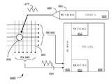
도 4는 측정된 캐패시턴스들을 터치 좌표들로 변환하는 캐패시턴스 센서(301) 및 N×M 전극 매트릭스(425)를 포함하는 용량성 감지 어레이(400) 감지 어레이의 일 실시예를 예시하는 블록도이다. 감지 어레이(400)는 예를 들어, 도 3의 터치 센서 패드 또는 터치 스크린(325)일 수 있다. N×M 전극 매트릭스(425)는 N×M개의 전극들(N개의 수신 전극들 및 M개의 전송 전극들)을 포함하고, 상기 N×M 전극 매트릭스(425)는 전송("TX") 전극(422) 및 수신("RX") 전극(423)을 더 포함한다. N×M 전극 매트릭스(425) 내의 전극들 각각은 전도성 트레이스들(450) 중 하나에 의해 캐패시턴스 센서(301)에 접속된다. 일 실시예에서, 캐패시턴스 센서(301)는 전하 축적 회로, 캐패시턴스 변조 회로, 또는 당업자들에게 알려진 다른 캐패시턴스 감지 방법들을 이용하여 동작한다. 실시예에서, 캐패시턴스 센서(301)는 터치 스크린 제어기들의 Cypress TMA-3xx 패밀리이다. 대안적으로, 다른 캐패시턴스 센서들이 사용될 수 있다. 상술된 바와 같은 상호 캐패시턴스 감지 어레이들, 또는 터치 스크린들은 시각적 디스플레이 그 자체(예를 들어, LCD 모니터) 위에, 또는 그 안에, 또는 그 아래에 배치된 투명한, 전도성 감지 어레이를 포함할 수 있거나, 또는 디스플레이의 앞쪽에 투명한 기판을 포함할 수 있다. 실시예에서, TX 및 RX 전극들은 각각 행들 및 열들로 구성된다. 전극들의 행들 및 열들은, 임의의 선택된 조합으로 캐패시턴스 센서(301)에 의해 TX 또는 RX 전극들로서 구성될 수 있다는 것을 유의해야 한다. 일 실시예에서, 감지 어레이(400)의 TX 및 RX 전극들은, 터치 대상들을 검출하기 위해 제 1 모드에서 상호 캐패시턴스 감지 어레이의 TX 및 RX 전극들로서 동작하도록, 그리고 감지 어레이의 동일한 전극들 상의 스타일러스를 검출하기 위해 제 2 모드에서 전하 결합 수신기의 전극들로서 동작하도록 구성된다. 활성화될 때 스타일러스 TX 신호를 발생시키는 스타일러스는, 상호 캐패시턴스 감지 동안 수행되는 바와 같은, RX 전극 및 TX 전극(감지 엘리먼트)의 교차점(intersection)에서 상호 캐패시턴스를 측정하는 대신에, 용량성 감지 어레이에 전하를 결합시키기 위해 사용된다. 캐패시턴스 센서(301)는 감지 엘리먼트들의 캐패시턴스들을 측정하기 위해 상호 캐패시턴스 또는 자체-캐패시턴스 감지를 사용하지 않고 수행할 때 스타일러스가 할 수 있다. 오히려, 캐패시턴스 센서(301)는 본 명세서에 기술된 바와 같은 스타일러스와 감지 어레이(400) 사이에 용량성으로 결합되는 전하를 측정한다.4 is a block diagram illustrating one embodiment of a
N×M 전극 매트릭스(425)에서의 TX 및 RX 전극들이 수직으로 배열되어서, TX 전극들의 각각이 총 N*M개의 교차점들에서 RX 전극들의 각각을 교차하고 중첩하여, 어레이에 N*M개의 개별 감지 엘리먼트들을 생성한다. 따라서, 각각의 TX 전극은 RX 전극들의 각각과 용량성 결합된다. 예를 들어, TX 전극(422)은, TX 전극(422)과 RX 전극(423)이 중첩하는 포인트에서 RX 전극(423)과 용량성 결합된다. TX 및 RX 전극들(422 및 423)의 교차점들 각각은 용량성 감지 엘리먼트를 형성한다.The TX and RX electrodes in the N × M electrode matrix 425 are arranged vertically so that each of the TX electrodes crosses and overlaps each of the RX electrodes at a total of N * M intersections, so that N * M individual pieces in the array. Create sense elements. Thus, each TX electrode is capacitively coupled with each of the RX electrodes. For example, the
TX 및 RX 전극들 사이의 용량성 결합 때문에, 각각의 TX 전극에서의 TX 신호의 인가는 RX 전극들 각각에서 전류를 유도한다. 예를 들어, TX 신호가 TX 전극(422)에 인가될 경우, TX 신호는 N×M 전극 매트릭스(425)에서 RX 전극(423) 상에 RX 신호를 유도한다. 그 후, RX 전극들 각각 상의 RX 신호는, N개의 RX 전극들의 각각을 시퀀스로 복조 회로에 접속시키기 위해 멀티플렉서를 사용함으로써 시퀀스로 측정될 수 있다. TX 전극과 RX 전극 사이의 각각의 교차점과 연관된 캐패시턴스는, TX 전극과 RX 전극의 모든 이용가능한 조합을 선택함으로써 감지될 수 있다.Because of capacitive coupling between the TX and RX electrodes, the application of the TX signal at each TX electrode induces a current in each of the RX electrodes. For example, when the TX signal is applied to the
손가락과 같은 터치 오브젝트가 N×M 전극 매트릭스(625)에 접근할 경우, 오브젝트는 전극들 중 일부에만 영향을 주는 캐패시턴스에서의 감소를 초래한다. 예를 들어, 손가락이 TX 전극(422) 및 RX 전극(423)의 교차점 (감지 엘리먼트) 근처에 배치되면, 손가락의 존재는 2개의 전극들(422 및 423) 사이의 결합 커패시턴스를 감소시킨다. 또 다른 실시형태에서, 손가락의 존재는 2개의 전극들(422 및 423) 사이의 결합 캐패시턴스를 증가시킨다. 따라서, 터치패드 상의 손가락의 위치는, 변경된 캐패시턴스가 RX 전극 상에서 측정되었던 시간에 TX 신호가 인가되었던 TX 전극과 RX 전극 사이의 변경된 결합 캐패시턴스를 갖는 RX 전극 양자를 식별함으로써 결정될 수 있다. 따라서, N×M 전극 매트릭스(425)에서의 전극들의 각각의 교차점과 연관된 캐패시턴스들을 순차적으로 결정함으로써, 하나 또는 그 초과의 입력들의 위치들이 결정될 수 있다. 프로세스가 감지 엘리먼트들(감지 엘리먼트들의 각각에 대한 베이스라인(baseline)들을 결정함으로써 RX 및 TX 전극들의 교차점들)을 교정할 수 있음을 유의해야 한다. 또한, 본 발명의 이점을 갖는 당업자에 의해 인식될 바와 같이, 행/열 피치보다 더 양호한 해상도들로 손가락 위치를 검출하기 위해 보간이 사용될 수도 있음을 유의해야 한다. 부가적으로, 본 발명의 이점을 갖는 당업자에 의해 인식될 바와 같이 터치의 중심을 검출하기 위해 중심값(cetroid) 알고리즘들의 다양한 타입들이 사용될 수도 있다.When a touch object, such as a finger, approaches the N × M electrode matrix 625, the object results in a reduction in capacitance that affects only some of the electrodes. For example, if a finger is placed near the intersection (sense element) of the
즉, 짧은 시간 기간 동안 TX 전극들의 각각의 행에 송신 신호를 인가하고, 그 기간 동안 TX 전극들의 그 행으로부터 RX 전극들의 열들의 각각까지 결합된 전하의 양을 감지함으로써, 감지가 달성된다. 일 실시형태에서, (도 5a에 도시된 바와 같이) 각각의 교차점에서의 TX 전극들로부터 RX 전극들로 결합된 전하는, 전하 측정들의 맵이 전체 스크린에 대해 생성될 때까지, 한번에 하나의 열로 측정된다. 다른 실시형태들에서, 도 5b에 도시된 바와 같이, 감지 채널들보다 더 많은 열들이 존재하면, 각각의 행은 2회 구동되고 순차적으로 멀티플렉싱될 필요가 있을 수도 있다. 당업자에 의해 인식될 바와 같이, 스캐닝 패턴들의 다른 변경들이 사용될 수도 있다. 또한, 터치 센서 패드 상의 입력의 위치를 표시하는 터치 위치 좌표들로의 유도된 RX 신호의 변환이 당업자에 의해 이해될 것이다.That is, sensing is achieved by applying a transmission signal to each row of TX electrodes for a short period of time, and sensing the amount of charge coupled from that row of TX electrodes to each of the columns of RX electrodes during that period. In one embodiment, the charge coupled from the TX electrodes to the RX electrodes at each intersection (as shown in FIG. 5A) is measured one row at a time until a map of charge measurements is generated for the entire screen. do. In other embodiments, as shown in FIG. 5B, if there are more columns than the sense channels, each row may need to be driven twice and multiplexed sequentially. As will be appreciated by those skilled in the art, other variations of scanning patterns may be used. Further, the conversion of the derived RX signal into touch position coordinates indicating the position of the input on the touch sensor pad will be understood by those skilled in the art.
본 발명의 이점을 갖는 당업자에 의해 인식될 바와 같이, TX 및 RX 전극들(422 및 423)이 도 4에서 바들 또는 연장된 직사각형들로서 나타나면, 대안적인 실시형태들은, 다이아몬드들, 마름모꼴들, 갈매기 무늬(chevron)들, 및 다른 사용가능한 형상들과 같은 다양한 바둑판 무늬(tessellated) 형상들을 사용할 수도 있다.As will be appreciated by those skilled in the art having the benefit of the present invention, if TX and
도 6a는 측정된 캐패시턴스들을 터치 좌표들로 변환하는 터치 스크린 제어기(605) 및 감지 어레이(400)를 포함하는 시스템(600)의 일 실시형태를 도시한 블록도이다. 일 실시형태에서, 터치 스크린 제어기(605)는 상술된 캐패시턴스 센서(301)와 유사하다. 또 다른 실시형태에서, 터치 스크린 제어기(605)는 프로세싱 디바이스(310)이다. 감지 어레이(400)는 TX 라인들(635) 및 RX 라인들(640)을 포함한다. 일 실시형태에서, TX 라인들(635) 및 RX 라인들(640)은, 각각, 도 4의 TX 전극들(422) 및 RX 전극들(423)이다. 터치 스크린 제어기(605)는 TX 구동 회로(610), RX 감지 회로(620), 및 멀티플렉서(630)를 포함한다.FIG. 6A is a block diagram illustrating one embodiment of a
일 실시형태에서, 패시브 오브젝트(예를 들어, 손가락 또는 다른 도전성 오브젝트)는 접촉 포인트(645)에서 감지 어레이(400)를 터치한다. TX 구동 회로(610)는 TX 신호(632)를 이용하여 TX 라인들(635)을 구동한다. RX 감지 회로(620)는 RX 라인들(640) 상에서 RX 신호(634)를 측정한다. 일 실시형태에서, 터치 스크린 제어기(605)는, 도 4-5와 관련하여 상술된 매핑 기술들에 기초하여 접촉 포인트(645)의 위치를 결정한다. TX 라인들(635) 및 RX 라인들(640)은 멀티플렉서(630)에 의해 멀티플렉싱된다. 터치 스크린 제어기(605)는 TX 라인들(635)(미도시) 상에서 TX 신호(632)를 제공하고, RX 라인들(640)(열들) 상에서 캐패시턴스를 측정한다. 일 실시형태에서, TX 및 RX 라인들(635, 640)은 직교하며, 상호교환가능하게 사용될 수도 있다 (예를 들어, 열들 상에서 송신하고 행들 상에서 수신함). 일 실시형태에서, TX 구동 회로(610)는 높은 임피던스 ITO 패널(TX 라인들(635))을 통해 TX 신호(632)를 송신하며, 따라서, 시스템의 주파수 상한 및 속도 상한을 제한한다. 또한, 총 스캔 시간은 감지 어레이(400)의 TX 라인들(635) 및 RX 라인들(640)의 수에 의존할 수도 있다. 예를 들어, 일 실시형태에 따르면, TX 구동 회로(610)는 각각의 TX 라인(635) 상에서 TX 신호(632)를 제공하며, 동시에, 각각의 RX 라인(640) 상의 용량성 결합된 RX 신호(634)를 판독한다. 또 다른 실시형태에서, 도 5b와 관련하여 설명된 바와 같이, RX 라인들(640)은 2개 또는 그 초과의 스캔들로 멀티플렉싱된다.In one embodiment, a passive object (eg, a finger or other conductive object) touches the
도 6b는, 감지 어레이(400), 스타일러스(680), 및 측정된 캐패시턴스들을 터치 좌표들로 변환하는 터치 스크린 제어기(605)를 포함하는 시스템(600)의 일 실시형태를 도시한 블록도이다. 감지 어레이(400)는 RX 라인들(640 및 660)을 포함한다. RX 라인들(660)은 도 6a의 TX 라인들(635)과 동일하지만, 추가적으로 후술될 바와 같이 시스템(600)에서 수신 감지 채널로서 사용된다. 일 실시형태에서, RX 라인들(640 및 660)은 도 4의 TX 전극들(422) 및 RX 전극들(423)과 유사하다. 터치 스크린 제어기(605)는 TX 구동 회로(610), RX 감지 회로(620), 및 멀티플렉서(630)를 포함한다. 스타일러스(680)는 TX 구동 회로(685) 및 스타일러스 팁(688)을 포함한다.6B is a block diagram illustrating an embodiment of a
실시예에서, 스타일러스(680)의 스타일러스 TX 구동 회로(685)는 감지 어레이 상의 접촉점(695)에 직접적으로 TX 신호(677)를 제공하고, 따라서 TX 구동 회로(610)로부터의 TX 신호를 송신하기 위해 RX 660 라인들(앞서, 도 6a에서, TX 635)을 전용시킬 필요가 제거된다. 이와 같이, RX 감지 회로(620)는 감지 어레이의 행들(RX 라인들(660))과 열들(RX 라인들(640)) 둘 다에서 RX 신호(634)를 측정한다. 이는, 더 빠른 위치 추적을 야기시키는데, 그 이유는 TX 신호가 더 이상 고임피던스 ITO 라인들을 통과하지 않아서, 전도성 오브젝트에 대한 상호-캐패시턴스 감지 때보다 스타일러스 감지 동안 더 빠른 스캔 시간이 야기되기 때문이다. 일 실시예에서, 터치 스크린 제어기(605)는 TX 구동 회로(660)(도 6a에 도시됨)로부터의 TX 신호의 RX 감지 동안 감지 어레이(400)의 정상 스캔을 수행하고, 그리고 스타일러스 TX 신호(677)(도 6b에 도시됨)의 RX 감지 동안 감지 어레이(400)의 스타일러스 스캔을 수행한다. 스타일러스 스캔을 위해, 터치 스크린 제어기(605)는 스타일러스로부터 감지 어레이의 행 전극 및 열 전극에 용량성으로 결합되는 전하를 측정한다. 추가로 예시하기 위해, 상호 캐패시턴스 스캔은, 오브젝트를 위치시키고 그리고 추적하기 위해 TX 및 RX 신호(632, 634) 둘 다를 사용한다. 위에 설명된 바와 같이, 이는, 통상적으로, 터치 스크린 제어기(655)에 의해 연속적인 방식으로 각각의 구동된 TX 라인(635)에 대해 RX 라인들(640) 각각을 감지함으로써 이루어진다. N개 행들(TX 신호)과 M개 열들(RX 신호)의 어레이에서, 한 번에 하나의 RX 라인이 감지된다면, 전체 스캔은 N×M회의 총 스캔들을 요구할 것이다. 예컨대, 순차적인 방식으로, 행 1을 통해 TX 신호("TX'ing")를 송신하고 그리고 열들 1-M을 통해 수신 신호("RX'ing")를 수신하는 것 뒤에는, 행 2를 통해 TX'ing를 송신하고 그리고 열들 1-M을 통해 RX'ing를 수신하는 것이 이어지는 등등이다.In an embodiment, the stylus
대안적으로, 한 번에 더 많은 RX 라인들이 감지될 수 있다. 일 실시예에서, 한 번에 4개 또는 8개 RX 라인들이 감지되지만, 다른 실시예들에서, RX 라인들 전부가 동시에 또는 순차적으로 감지될 수 있다. 하나보다 많은 RX 라인을 동시에 감지하기 위한 다중 RX 채널들을 이용하여, 전체 스캔은 (N*M)/(RX 채널들의 #)일 것이다. 대조적으로, 스타일러스 스캔은 TX 구동 회로(610)에 의한 TX 신호를 요구하지 않고, 그리고 전체 스캔은 각각의 행 및 열 상에서 단일 RX 신호 측정만을 요구할 것이거나 또는 N+M회의 스캔들을 요구할 것이고, 따라서 전체 감지 어레이에 대한 상호 캐패시턴스 스캐닝 시간과 비교할 때 전체 감지 어레이에 대해 상당히 감소된 스타일러스 스캐닝 시간이 야기된다. 위처럼, 다중 RX 라인들을 동시에 감지하기 위해, 다중 RX 채널들이 사용될 수 있다. 이 경우, 전체 스캔은 (N+M)/(RX 채널들의 #)일 것이다.Alternatively, more RX lines can be sensed at one time. In one embodiment, four or eight RX lines are sensed at one time, but in other embodiments, all of the RX lines may be sensed simultaneously or sequentially. With multiple RX channels to detect more than one RX line simultaneously, the full scan will be (N * M) / (# of RX channels). In contrast, the stylus scan does not require a TX signal by the
위에 설명된 바와 같이, 위에 설명된 다양한 터치 스크린들과 인터페이싱하기 위해 패시브 스타일러스가 터치 오브젝트로서 사용될 수 있다. 패시브 스타일러스들과 대조적으로, 여기서 설명되는 액티브 스타일러스는 송신("TX") 신호를 제공하고, 상기 송신("TX") 신호는 도 6a 및 도 6b와 함께 위에서 설명된 바와 같이 손가락 감지 모드들에서 터치 스크린 제어기(605)에 의해 통상적으로 제공된다. 스타일러스는, 전하를 용량성 감지 어레이로 결합시키기 위해 사용되고, 그리고 용량성 감지 어레이는, 스타일러스를 검출하기 위한 전하 결합 수신기로서 동작한다. 전하 결합 수신기로서 동작할 때, 용량성 감지 어레이는 상호 캐패시턴스 또는 자가-용량성 감지를 사용하지 않는다. 예컨대 상호 캐패시턴스 감지를 이용하여, 터치 오브젝트들을 검출할 때, 상이한 모드에서 동일한 용량성 감지 어레이가 동작될 수 있다.As described above, the passive stylus can be used as a touch object to interface with the various touch screens described above. In contrast to passive stylus, the active stylus described herein provides a transmit ("TX") signal, which transmits ("TX") signal in finger detection modes as described above in conjunction with FIGS. 6A and 6B. Typically provided by
도 4-도 6과 함께 위에서 설명된 바와 같이, 스타일러스(680)는 스타일러스 TX 신호(677)를 감지 어레이(400)에 용량성으로 결합시킨다. 실시예에서, 스타일러스 신호 진폭, 주파수, 위상 등은, 터치 스크린 제어기(605)에 의한 손가락 감지를 위해 사용되는 것과 동일할 수 있거나 또는 유사할 수 있다. 대안적으로, 스타일러스 TX 신호는, 진폭, 주파수, 및 위상에 있어서, TX 구동 회로(610)로부터의 TX 신호와 상이할 수 있다. 다른 실시예에서, 스타일러스 TX 신호는, 코드 변조를 위해, TX 구동 회로(610)로부터의 TX 신호 내에 사용된 시퀀스와 상이한 시퀀스를 가질 수 있다. 예시적 실시예에서, 스타일러스 TX 신호(677)는 TX 구동 회로(610)로부터의 손가락 감지 TX 신호(632)보다 더 큰 진폭을 갖는다. 예컨대, 일 예시적 실시예에서, 터치 스크린 제어기(605)에 의해 통상적으로 제공되는 대략 5-10V와 비교할 때, 스타일러스 TX 신호(635)는 대략 20-50V의 범위에 있다. 대안적으로, 기술분야의 당업자에 의해 인식될 바와 같이, 다른 전압들이 사용될 수 있다. 스타일러스 TX 전압이 높을수록 더 많은 전하가 MC 어레이(400)에 더욱 신속하게 결합되고, 따라서 감지 어레이(400)의 각각의 행 및 열을 감지하는데 요구되는 시간량이 감소된다. 손가락 감지를 위한 유사한 시간 효율성 개선들을 획득하기 위해, 다른 실시예들은 MC 어레이 TX 라인(635) 상에 더 높은 전압들을 포함할 수 있다.As described above in conjunction with FIGS. 4-6, the
실시예에서, 감소된 감지 시간을 달성하기 위해, 스타일러스(680)는, TX 구동 회로(610)로부터의 TX 신호(632) 주파수보다 더 높은 주파수를 스타일러스 TX 신호(677)에 인가한다. 스타일러스 TX 신호(677)의 상승 에지 및 하강 에지 동안 스타일러스(680)로부터 감지 어레이(400)로 전하가 용량성으로 결합될 수 있다. 따라서, 더 높은 TX 주파수는 주어진 시간 기간에 걸쳐 더 많은 개수의 상승 에지 및 하강 에지를 제공하여, 낮은 주파수에 의해서보다 주어진 기간 내에 더 큰 전하 결합을 야기시킨다. 손가락 감지 모드에서의 TX 주파수의 현실적 상한 치수(예컨대, 손가락 감지를 위한 감지 어레이(400) 상의 TX 신호)는 개별 감지 엘리먼트들 및 인터커넥트(미도시)의 레지스터-캐패시터("RC") 시간 상수에 따라 좌우된다. 그 이유는, 통상적으로, 감지 어레이(400)의 제작시 사용되는 고임피던스 재료들(예컨대, ITO) 때문이다. 고-임피던스 감지 어레이(400)는 높은 시간 상수와 센서들의 행들(TX 라인들(635)) 및 열들(RX 라인들(640))의 결과적 신호 감쇠를 야기시킬 수 있고, 이는 최대 감지 주파수를 제한시킬 수 있다. 스타일러스 TX 신호(677)를 감지 어레이(400) 상의 접촉점으로 직접적으로 송신하기 위해 액티브 스타일러스를 사용할 때, 스타일러스 TX 신호(677)는 고 임피던스 경로 전부를 통과할 필요가 없고, 그리고 그러므로 도 6a 및 도 6b와 함께 위에서 설명된 바와 같이 스타일러스 TX 신호(677)에 대한 최대 동작 주파수는 증가될 수 있다. 예컨대, RX 트레이스(trace)들(행들 및 열들 둘 다)의 시간 상수는, 상한 주파수 치수를 결정하기 위해 사용될 수 있지만, 이는, 통상적으로, 손가락 감지시 사용되는 상한 주파수 치수의 적어도 두 배이다. 통상적으로, 상기 임피던스는 상호 캐패시턴스 스캐닝을 수행할 때의 임피던스의 절반인데, 그 이유는 행의 임피던스가 제거되고 그리고 열의 임피던스가 유지(또는 그 반대)되기 때문이다. 손가락 감지 및 스타일러스 감지 둘 다가 주파수 선택을 사용하고, 여기서 동작 기간은 패널의 시간 상수보다 더 작아야 한다는 것이 주의되어야 한다; 그래서, 동작 주파수 선택에 대한 제약들은 손가락 및 스타일러스 감지에 대한 제약들과 대략 동일하다.In an embodiment, to achieve a reduced sensing time, the
실시예에서, 스타일러스 TX 신호(677)의 주파수는 손가락 감지 TX 신호(632)의 주파수와 상이하다. 상이한 TX 주파수들을 이용함으로써, 터치 스크린 제어기(605)는 스타일러스 TX 신호들과 손가락 감지 TX 신호들 사이를 구별할 수 있다. 이는, 제어기가 상호 캐패시턴스 감지를 수행하고 있을 때 적용된다. 제어기가 TX 라인들 중 어느 것도 구동하고 있지 않다면, 검출된 임의의 RX 신호들이 스타일러스로부터 온 것으로 추론될 수 있다. 대안적으로, 본 기재의 이익을 이용하는 기술분야의 당업자에 의해 인식될 바와 같이, 터치 스크린 제어기(605)는, 차이가 신호 특징들(예컨대, 위상, 주파수, 진폭, 및 코드 변조)임을 검출하는 것과 같이, 다른 기술들을 이용하여, TX 구동 회로(610) TX 신호들(632)로부터 스타일러스 TX 신호들을 구별할 수 있다.In an embodiment, the frequency of the
일 실시예에서, 스타일러스(680)는 터치 스크린 제어기(655)에 의해 이용된 부가적인 데이터를 포함하도록 스타일러스 TX 신호(677)를 인코딩한다. 이러한 부가적인 정보는 사용자가 스타일러스(680)로부터 부가적인 기능을 획득하는데 유용할 수 있다. 예를 들어, 부가적인 정보는 부가적인 버튼들, 슬라이더들 또는 스타일러스(680) 상의 다른 운용자 작동 제어들의 상태를 포함할 수 있다. 부가적인 버튼들은 전기적(예를 들어, 버튼들, 전위차계(potentiometer)들), 유도성 또는 용량성일 수 있다. 일 실시예에서, 스타일러스 팁(688)이 터치 스크린 또는 감지 어레이(400)에 대해 눌러지는 힘 감지 또는 압력이 스타일러스(680)에 의해 검출되고 스타일러스 TX 신호(677)에서 인코딩된다. 스타일러스(680) 내의 힘은 패시브 센서(예를 들어, 힘 감지 레지스터 또는 커패시터) 또는 액티브 센서(예를 들어, 용량성 선형 위치 센서 또는 코일에 대한 이동 엘리먼트)에 의해 검출될 수 있다. 또한, 스타일러스의 배향 또는 가속도는 (예를 들어, 가속도계에 의해) 검출되고 더 나은 스타일러스(680) 기능을 위해 스타일러스 TX 신호에 인코딩될 수 있다. 이러한 부가적인 정보는 스타일러스(680)로부터 터치 제어기(605)로 다양한 방식들로 전송될 수 있으며 스타일러스 TX 신호(677)를 변조하는 것으로 제한되지 않는다. 팁 힘(tip force)은 예를 들어, 스타일러스가 스크린에 접촉할 때 검출하거나, 또는 "탭 제스처(tap gesture)", 또는 "더블-탭(double-tap)" 제스처 등과 같은 제스처들을 검출하도록 드로잉 프로그램(drawing program)의 라인 폭을 변화시키는데 이용될 수 있다.In one embodiment,
일 실시예에서, 스타일러스(680)는 변조를 이용하여 부가적인 데이터로 스타일러스 TX 신호(677)를 인코딩한다. 이러한 변조는 주파수 변조("FM"), 주파수-시프트 키잉("FSK"), 진폭 변조("AM"), 진폭-시프트 키잉("ASK"), 온-오프 키잉("OOK"), 펄스 위치 변조, 위상 변조("PM"), 맨체스터 인코딩, 직접 시퀀스 스프레드 스펙트럼("DSSS"), 및 당업자들에 의해 인지되는 다른 변조 방식을 포함할 수 있다. PM 변조는 이진 위상 시프트 키잉("BPSK") 또는 직교 위상 시프트 키잉("QPSK") 인코딩 방식들을 추가로 포함할 수 있다.In one embodiment, the
대안적인 실시예들은 스타일러스 TX 신호(677)를 변조하는 대신 스타일러스(680)로부터 터치 스크린 제어기(605)로 부가적인 데이터를 전달하도록 구현될 수 있다. 일 실시예에서, 스타일러스(680)는 스타일러스 TX 신호(677)로부터 개별적으로, 그러나 동일한 용량성 결합을 이용하여 감지 어레이(400)로 부가적인 데이터를 전송한다. 예를 들어, 시분할 멀티플렉싱("TDM")에서 스타일러스(680)는 하나의 시간 슬롯에서 스타일러스 TX 신호(677)를 전송하고 다른 시간 슬롯에서 부가적인 데이터(예를 들어, 힘 데이터, 가속 데이터)를 전송한다. 일 실시예에서, 스타일러스 TX 신호(677) 및 부가적인 데이터는 동일하거나 상이한 주파수들을 활용한다. 다른 실시예에서, 스타일러스 TX 신호(677) 및 부가적인 데이터는 이전에 기술된 변조 방법들 중 하나 이상을 활용한다. 부가적인 실시예들에서, 광학적, 초음파적, 유도성 또는 RF 신호 전송들은 스타일러스(680)로부터 터치 스크린 제어기(655)로 부가적인 데이터를 전달하는데 활용될 수 있다. 안테나 및 증폭기들과 같은 부가적인 하드웨어는 별개의 통신 링크 상에서 부가적인 데이터를 전달하는데 필요할 수 있다는 것이 주의되어야 한다.Alternative embodiments may be implemented to pass additional data from the
일 실시예에서, 스타일러스(680)의 전력 소모를 최소화하고 배터리 수명을 최대화하기 위해, 스타일러스(680)가 감지 어레이(400)를 터치하거나 그 부근에 있지 않으면 스타일러스(680)는 스타일러스 TX 신호(677)를 생성하거나 전송하지 않는다. 일 실시예에서, 사용자는 스타일러스 TX 신호(677)를 생성하기 시작하도록 온/오프 스위치를 동작시킨다. 도 7a는 온/오프 스위치(705)를 포함하는 스타일러스(700)의 일 실시예를 예시하는 블록도이다. 일 실시예에서, 온/오프 스위치(705)는 액추에이터를 누르고, 회전시키고, 또는 미끄러지게 함으로써 인에이블(즉, "오프" 위치로부터 "온" 위치로 스위칭되고 그 반대로 스위칭됨)되도록 구성되는 액추에이터일 수 있다. 온/오프 스위치(705)는 당업자들에게 알려진 기계적, 전기적 또는 다른 타입의 수동형 스위치일 수 있다.In one embodiment, to minimize power consumption of the
도 7b는 스타일러스가 이용중일 때를 검출하기 위해 용량성 감지 엘리먼트(730)를 포함하는 스타일러스(720)의 일 실시예를 예시하는 블록도이다. 일 실시예에서, 스타일러스(720)는 도 7a와 함께 위에서 기술되는 것과 유사한 온/오프 스위치(725)를 포함한다. 온/오프 스위치(725)는 수면 모드와 조합된다. 수면 모드는 스타일러스(720)가 현재 사용자에 의해 사용중인지를 검출하기 위해 스타일러스(720)가 적은 양의 전력을 이용하는 저 전력 모드이다. 예를 들어, 사용자가 온/오프 스위치(725)를 누름으로써 스타일러스(720)를 턴 온시키고, 스타일러스(720)는 스타일러스 TX 신호(677)를 전송하기 시작한다. 비-사용의 미리 결정된 기간 이후에, 스타일러스(720)는 저 전력 상태("수면 모드")에 진입하고 스타일러스 TX 신호(677)의 전송을 중지한다. 스타일러스(720)는 터치 오브젝트(예를 들어, 손가락, 손 등)가 용량성 감지 엘리먼트(730) 상에서 검출될 때까지 저 전력 상태에 머무른다. 일 실시예에서, 스타일러스(720)는 이용을 검출하기 위해(예를 들어, 매 25ms 마다) 커패시턴스 감지 엘리먼트(730) 상에서 커패시턴스를 주기적으로 측정하지만; 검출 기간 또는 듀티 사이클은 필요에 따라 구성될 수 있다. 터치 오브젝트의 검출 시에, 스타일러스(720)는 미리 결정된 기간이 경과하거나 사용자가 온/오프 스위치(725)를 통해 스타일러스를 턴 오프할 때까지 스타일러스 TX 신호(677)를 재전송하기 시작한다. 다른 실시예에서, 스타일러스(720)는 저 전력 상태에서 미리 결정된 기간이 경과한 이후 스타일러스를 턴 오프한다.7B is a block diagram illustrating one embodiment of a
도 7c는 다수의 기능적 성능들을 갖는 스타일러스 팁(745)을 포함하는 스타일러스(740)의 일 실시예를 예시하는 블록도이다. 일 실시예에서, 스타일러스 팁(745)은 스타일러스 팁(745)이 감지 어레이(400) 또는 터치 패널(도시되지 않음)과 접촉하게 될 때 기계적 압력(예를 들어, 힘 데이터)을 감지하도록 구성된다. 스타일러스(740)는 "감지 시에 깨어남(wake on force sensing)"을 이용하도록 구성될 수 있다. 예를 들어, 스타일러스(740)는 도 7b와 함께 유사하게 기술되는 바와 같이, 스타일러스(740)의 이용을 검출하여 저 전력 수면 모드로부터 액티브 스타일러스 TX 전송 모드로 동작 모드를 변경하기 위해 힘 데이터를 활용한다. 다른 실시예들에서, 스타일러스(740)는 힘 신호가 존재하는 동안 스타일러스 TX 신호(677)를 전송하고 부가적인 시간 외 기간(예를 들어, 15초) 동안 액티브 상태로 머무른다. 일 실시예에서, 스타일러스 팁(745)은 또한 터치 스크린 TX 신호(TX 신호(632))를 검출하고, 액정 디스플레이("LCD") 노이즈를 검출하고 및/또는 LCD 광학 신호들을 검출함으로써 이용을 검출할 수 있다. 도 7a 내지 도 7c에서 기술되는 특징들은 단독으로 또는 이들의 임의의 조합으로 이용될 수 있다.7C is a block diagram illustrating one embodiment of a
도 8은 스타일러스(800)의 일 실시예를 예시하는 블록도이다. 스타일러스(800)는 파형 생성기(810), 파 형상화기(830) 및 인에이블 블록(850)을 포함한다. 일 실시예에서, 파형 생성기(810)는 오실리에이터이다. 오실리에이터는 수정, 세라믹 공진기, 링 오실리에이터, CPU 내부 오실리에이터, 완화 오실리에이터, 또는 당업자들에게 알려진 다른 파형 생성 회로들일 수 있다. 일 실시예에서, 파형 생성기(810)는 스타일러스 TX 신호(820)를 생성하고 추가의 프로세싱을 위해 이를 파 형상화기(830)에 결합한다.8 is a block diagram illustrating one embodiment of a
파 형상화기(830)는 수신 터치 스크린 제어기(도시되지 않음)에 의해 요구되는 바와 같이 TX 신호(820)의 주파수, 듀티 사이클, 위상, 또는 진폭을 형상화하도록 구성될 수 있다. 820, 840 및 860의 구형파는 실제 신호 파형을 나타내도록 의도되는 것이 아니라, 일반적으로 단지 신호의 존재를 나타낸다는 것이 주의될 것이다. 파 형상화기(830)는 도 6b와 함께 위에서 기술되는 바와 같이 TX 신호(820)를 변조 또는 인코딩하도록 구성된다. 일 실시예에서, 파 형상화기(830)는 TX 신호(840)를 인에이블 블록(850)에 결합한다. 몇몇 애플리케이션들에서, 파 형상화기(830)는 TX 신호 생성의 통합 부분이 아닐 수 있다. 예를 들어, 파형 생성기(810)로부터의 TX 신호(820)는 부가적인 파 형상화를 요구하지 않을 수 있다. 그럼으로써 몇몇 실시예들은 스타일러스(800) 설계에 있어 파형 형상화기(830)를 요구하지 않을 수 있다.
실시예에서, 인에이블 블록(850)은, 예를 들면, 도 7c와 관련하여 상술된 바와 같이, 저전력 또는 휴면 모드 동작을 인에이블하도록 구성된다. 인에이블 블록(850)은 도 8에 도시된 바와 같이 개별적인 블록으로서 기능할 수 있거나, 파형 생성기(810) 또는 파형 정형기(830) 블록들에 통합될 수 있다. 실시예에서, 인에이블 블록(850)은 파형 생성기(810) 및/또는 파형 정형기(830) 블록들에 대한 피드백 경로를 제공하여, 액티브 및 휴면 모드들 동안에 그들의 활동을 제어한다. 예를 들면, 스타일러스(800)가 사용자 비활동으로 인해 액티브로부터 휴면 모드로 스위칭되어야 한다고 인에이블 블록(850)이 결정하면, 인에이블 블록(850)은 파형 생성기(810) 및 파형 정형기(830)가 TX 신호(820, 840)를 생성하는 것을 정지시키기 위한 피드백 신호(870)를 제공한다. 일 실시예에서, 인에이블 블록(850)은 스타일러스 액티브 모드에서 TX 신호(860)를 스타일러스 팁(도시되지 않음)에 연결한다.In an embodiment, enable
실시예에서, 스타일러스(800)는 하나 이상의 AAA 전지들, 단추형 전지들, 보청기 배터리들 등과 같은 로컬 1차 배터리로부터 전력을 공급받을 수 있다. 대안적으로, 니켈 및 리튬 기반 배터리들, 가요성 고분자 전지들, 연료 전지들뿐만 아니라 슈퍼 또는 울트라-커패시터들을 포함하는 재충전 가능 전지들이 사용될 수 있지만, 이에 제한되지 않는다. 스타일러스(740)는 또한 충전소 구성에서와 같이 터치 스크린 내에 하우징될 수 있거나, 당업자에 의해 이해될 바와 같이, 저항성, 용량성 또는 유도성 수단을 통해 전력을 수신할 수 있다.In an embodiment, the
실시예에서, 스타일러스(800)는 도 6a의 터치 스크린 TX 구동 회로(610)에 의해 제공된 TX 신호(632)와 전기적으로 유사하게 보이는 TX 신호(860)를 전송하도록 구성된다. 일 실시예에서, 터치 스크린 제어기(도시되지 않음)는 Cypress CY8CTMA300 프로세서이다. 대안적으로, 다른 터치 스크린 제어기들이 사용될 수 있다. 당업자들에게 알려진 바와 같이, 다른 TX 파형(예를 들면, 사인, 삼각형, 확산 스펙트럼) 및 동작 주파수들이 사용될 수 있지만, 터치 스크린 제어기는 통상적으로 100 KHz 내지 300 KHz 범위의 구형파 TX 신호(820, 840, 860)를 생성한다.In an embodiment, the
액티브 스타일러스(680)를 지원하는 상호 커패시턴스 터치 스크린 시스템이 본원에 기재되고, 여기서 스타일러스는 타이밍 "마스터"로서 동작하도록 구성되고, 터치 스크린 제어기(605)는 스타일러스가 사용중일 때 스타일러스(680)의 타이밍과 매칭하도록 그의 타이밍을 조절한다. 다시 말해서, 터치 스크린 제어기(305)는 감지 어레이(400)와 스타일러스(680)를 동기화하도록 구성된다. 본원에 기재된 다양한 실시예들은 언테더드(untethered)를 사용하는 임의의 상호 커패시턴스 터치 스크린 시스템, 또는 상호 커패시턴스 어레이에 용량적으로 연결되도록 구성된 무선 액티브 스타일러스에 적용 가능하고, 여기서 스타일러스는 터치 스크린 제어기로부터 동기화 또는 타이밍 데이터를 수신하지 않는다. 또한, 다양한 상이한 시퀀스 단계들 및 동기화에 관련된 프로세스의 타이밍은, 호스트에 의해 동기화를 수행하는 시스템들과 대조적으로, 스타일러스에 의해 전송된 TX 신호들로부터 유도된다.A mutual capacitance touch screen system that supports an
시스템(600)의 실시예의 동작, 및 시스템(600)의 상이한 동작 모드들 사이에 발생하는 타이밍 전환들을 충분히 설명하기 위해, 오프 상태의 시스템(600)으로 시작하는 예시적인 시퀀스 이벤트들이 아래에 제공된다. 시작 시에, 사용자는 전원을 턴 온하고, 시스템(600)의 초기화 프로세스가 시작된다. 디스플레이(도시되지 않음)는 턴 온되고, 터치 스크린 서브시스템(시스템(600))이 초기화된다. 이러한 지점에서, 어떠한 손가락, 터치 물체 또는 스타일러스도 감지 어레이(400) 근처에 있지 않거나 이와 접촉하지 않는다.In order to fully illustrate the operation of an embodiment of the
도 9는 본 발명의 실시예에 따른, 어떠한 터치 오브젝트도 터치 스크린 상에 존재하지 않는 상호 커패시턴스 터치 스크린 시스템(600)에 대한 타이밍도(900)이다. 타이밍도(900)는 제어기 TX 신호(910), 제어기 RX 신호(920) 및 스타일러스 TX 신호(930)를 예시한다. 제어기 TX 신호(910)는 제어기 TX 펄스(912)를 포함한다. 제어기 RX 신호(920)는 "WFT"(wait-for-touch) 간격(922) 및 "WFS"(wait-for-stylus) 간격(923)을 포함한다. 실시예에서, 터치 스크린은 감지 어레이(400)를 포함한다.9 is a timing diagram 900 for a mutual capacitance
동작 시에, 사용자는 전원을 턴 온하고, 시스템이 초기화된다. 실시예에서, 시스템(600)은 미리 결정된 듀티 사이클에서 TX 구동 회로(610)에 의해 TX 신호(6321)를 전송함으로써 동작을 시작한다. 실시예에서, TX 신호(632)에 대한 듀티 사이클은, 시스템(600)의 개선된 전력 소멸을 위해 손가락 또는 스타일러스가 검출되는 액티브 모드에 대한 듀티 사이클보다 낮다. 각각의 WFT TX 감지 기간(912) 동안에, 제어기는 신호(632)를 생성하고, 터치 스크린 제어기(605)는 손가락이 감지 어레이(400) 상에 존재하는지를 검출하기 위해 WFT RX 감지 기간(922) 동안에 대응하는 RX 신호를 청취하고, 일 구현에서, WFT TX 감지 기간(912)은 WFT RX 감지 기간(922)과 실질적으로 동일한 시간에 발생할 수 있다. 각각의 WFT 간격(912/922) 후에, 터치 스크린 제어기(605)는 스타일러스 사용을 감지하기 위해 WFS 감지 기간(923) 동안에 WFS 감지 동작을 수행한다. WFS 간격(923)은, 터치 스크린 제어기(605)가 TX 신호(632)를 전송하지 않는 것을 제외하고, 상호 커패시턴스 WFT(922)와 유사하게 수행된다. 대신에, 터치 스크린 제어기(605)는 RX 감지를 수행하고, 미리 결정된 잡음 임계치를 초과하는 WFT(923) 간격(즉, WFS 기간(923) 동안에) 후에 발생하는 임의의 수신된 신호는 스타일러스(680) 신호인 것으로 결정된다. WFT/WFS 프로세스는, 어떠한 손가락, 터치 물체, 또는 스타일러스도 검출되지 않는 한 백그라운드 프로세스로서 계속되고, 시스템은 WFT/WFS 감지 기간들의 외에는 저전력 모드에 있을 수 있고, 어떠한 손가락 또는 스타일러스도 스크린에 근접하지 않을 때 낮은 전체 평균 전력 소모를 발생시킨다.In operation, the user turns on the power and the system is initialized. In an embodiment,
대안적인 실시예에서, 도 6b와 관련하여 상술된 바와 같이, WFT(상호 커패시턴스) 및 WFS(전하-결합)가 사용된다. 또 다른 실시예에서, 어떠한 감소된 듀티 사이클 WFT/WFS 모드도 존재하지 않고, 초기화 후에, 터치 스크린 제어기(605)는 어떠한 손가락 또는 스타일러스도 감지 어레이(400) 상에 존재하지 않는 경우에서조차 후술되는 바와 같이 손가락 추적을 시작한다.In an alternative embodiment, WFT (mutual capacitance) and WFS (charge-coupled) are used, as described above with respect to FIG. 6B. In another embodiment, there is no reduced duty cycle WFT / WFS mode, and after initialization, the
도 10은 본 발명의 실시예에 따른, 손가락이 터치 스크린 상에 존재하는 상호 커패시턴스 터치 스크린 시스템(600)에 대한 타이밍도(1000)이다. 타이밍도(1000)는 제어기 TX 신호(1010), 제어기 RX 신호(1020), 및 스타일러스 TX 신호(1030)를 예시한다. 제어기 TX 신호(1010)는 제어기 TX 펄스(1012)를 포함한다. 제어기 RX 신호(1020)는 WFT 간격(1022) 및 WFS 간격(102)을 포함한다.10 is a timing diagram 1000 for a mutual capacitance
동작시에, 사용자는 터치 스크린 상에 손가락을 올려놓는다. 터치 스크린 제어기(605)는 WFT 인터벌(912/922) 동안 손가락을 검출하고 손가락 추적 감지를 시작한다. 손가락 추적은 앞서 설명된 바와 같이, RX 라인들(열들)(640)의 일부 또는 전부 상에서의 RX 감지(1022) 동안 시퀀스(1012)에서 감지 어레이(400)의 일부 또는 모든 TX 라인들(행들)(635) 상에서 TX 신호들을 전송하는 것을 포함할 수 있다. 일 실시예에서, 스캐닝은 주기적으로(예를 들어, 10 ms 인터벌들에서) 또는 연속적으로(미도시) 행해질 수 있다. 일단 손가락이 검출되면, 제어기 TX 신호(1010)는, 예를 들어, 감지 동작의 신호대 잡음비를 개선하기 위해 제어기 TX 펄스들(1012)의 듀티 사이클을 증가시킬 수 있다. 상호 커패시턴스 감지(MCS) 기간(1022) 이후, 터치 스크린 제어기(605)는 기간(1023) 동안 WFS 동작을 수행한다. 일 실시예에서, WFS 인터벌(1023) 동안 열들 및/또는 행들의 일부 또는 전부는 핀 멀티플렉서(630)에 의해 함께 단락되거나 "연결되고(ganged)", 터치 스크린 제어기(605)는 스타일러스 TX 신호들(677)의 존재(그러나 위치는 아님)를 검출하기 위해 단일 센서로서의 전체 감지 어레이(400)를 스캐닝한다. 일단 스타일러스(680)의 존재가 검출되면, 터치 스크린 제어기(605)는 앞서 설명된 바와 같이 스타일러스를 위치확인하고 그리고/또는 추적한다. 대안적으로, 행들 및/또는 열들은 WFS 인터벌(1023) 동안 "연결되지" 않는다. WFS 인터벌(1023)은 통상적으로 MCS 기간들(1022)보다 지속기간이 더 짧다(예를 들어, 100-200 ㎲). 일 실시예에서, 터치 스크린 제어기(605)는 WFS 감지를 모든 WFT 인터벌 이후 수행하기보다는 주기적으로 수행한다. 예를 들어, WFS는 매 100 ms마다 또는 매 10개의 MCS 스캔들 이후 발생할 수 있다.In operation, the user places a finger on the touch screen. The
도 11은 본 발명의 일 실시예에 따라, 스타일러스(680)가 터치 스크린 상에 존재하는 상호 커패시턴스 터치 스크린 시스템(600)에 대한 타이밍도(1100)이다. 스타일러스는 1132 근처에서 나타나지만 초기에는 존재하지 않음을 주목해야 한다. 타이밍도(1100)는 제어기 TX 신호(1110), 제어기 RX 신호(1120) 및 스타일러스 TX 신호(1130)를 도시한다. 제어기 TX 신호(1110)는 제어기 TX 시그널링 기간들(1112, 1114, 1116 및 1118)을 포함한다. 제어기 RX 신호(1120)는 WFT 인터벌들(1122, 1124 및 1129)을 포함한다. 제어기 RX 신호(1120)는 WFS 인터벌들(1123 및 1125)을 더 포함한다. 스타일러스 TX 신호(1130)는 스타일러스 TX 펄스들(1132, 1134 및 1136)을 포함한다.11 is a timing diagram 1100 of a mutual capacitance
일 실시예(미도시)에서, 스타일러스(680)는 스타일러스 TX 신호들(1130)을 송신할 때 이를 연속적으로 송신한다. 다른 실시예에서, 스타일러스(680)는 스타일러스 TX 신호(1130)를 특정한 듀티 사이클에서 송신한다. 예를 들어, 스타일러스(680)는 스타일러스 TX 신호(1130)를 매 10 ms마다 2 ms 동안 송신한다. 다른 실시예에서, 스타일러스(680)는 듀티 사이클을 통해 버스트들을 송신할 수 있다. 예를 들어, 스타일러스(680)는 스타일러스 TX 신호(1130)를 총 4 ms 동안 50 ㎲의 갭(gap)들을 갖는 100㎲ 버스트들 동안 송신하고, 그 다음 6 ms 동안 송신을 중지한다. 당업자에 의해 인식되는 바와 같이, 다른 듀티 사이클들이 구현될 수 있다. 일 실시예에서, 듀티 사이클은, 스타일러스 팁(688)의 힘 센서가 터치 스크린과의 최초 접촉을 검출할 때 변할 수 있다. 다른 실시예에서, 스타일러스(680)는 접촉이 검출될 때까지 TX 신호(1130)의 송신을 시작하지 않을 수 있다. 그러나, 각각의 경우에, 일단 스타일러스(680)가 터치 스크린과 접촉하면, 스타일러스는 미리 결정된 듀티 사이클에서 또는 버스트 패턴으로 또는 연속적으로 송신을 시작할 것이다.In one embodiment (not shown), the
일 실시예에서, 터치 스크린 제어기(605)는 스타일러스 TX 신호(1130)를 감지하고, 스타일러스 신호의 RX 감지가 시작하기 전에 RX 감지 타이밍을 스타일러스 TX 신호(1130)와 동기화한다. 통상적으로, 스타일러스 TX 신호(1130)는 검출하기 용이하고, 고-임피던스 RX 감지 회로(통상적으로 ITO가 고 임피던스 재료임)에 의해 터치 스크린 제어기(605)와 동기화하기 용이하다. 상대적으로 낮은 임피던스 RX 감지 회로를 이용하는 실시예에서, 스타일러스 TX 신호(1120)가 검출되기에 충분히 높은 임피던스가 되도록, RX 감지 회로를 감지 어레이(400) 상의 개별적인 센서들로부터 전기적으로 연결해제시키는 것이 필수적일 수 있다.In one embodiment, the
일 실시예에서, 터치 스크린 제어기(605)의 RX 감지 회로들을 검출하고 이를 스타일러스 TX 신호(1120)에 고정시키기 위해 위상 고정 루프("PLL")(미도시)가 이용될 수 있다. 통상적으로, 터치 스크린 제어기(605)는 위상 고정 프로세스를, 단순히 WFS 감지 동안이 아닌, 각각의 RX 감지 동작의 시작시에 (타이밍도(1100)에 도시된 바와 같이) 스타일러스 모드로 수행한다. PLL은 아날로그 기반 또는 디지털 기반일 수 있다. 일 실시예에서, 디지털 PLL은 펌웨어에서 구현된다.In one embodiment, a phase locked loop (“PLL”) (not shown) may be used to detect the RX sensing circuits of the
동작시에, 시스템(600)은 터치 스크린 상의 터치 오브젝트 또는 스타일러스로부터의 최초 터치 이전에는 초기에 WFT/WFS 모드일 것이다(예를 들어, WFT(1122) 및 WFS(1123)). 액티브 및 인에이블된 스타일러스(680)는 터치 스크린과 접촉하고 기간(1132) 동안 TX 신호를 송신한다. 일 실시예에서, 터치 스크린 제어기(605)는 WFS 인터벌(1125) 동안 스타일러스 TX 신호(1132)를 검출한다. 그 다음, 터치 스크린 제어기(605)를 스타일러스(680)에 동기화하기 위한 충분한 타이밍 정보를 획득하기 위해, 제어기 RX 신호(1120)는 다음 스타일러스 TX 펄스(1134)를 검출하도록 액티브(제어기 RX 기간(1126))로 유지된다. 제어기 RX 기간(1126)의 종료시까지 터치 스크린 제어기(605)는 스타일러스 TX 신호(1130)와 동기화를 구축한다. 통상적으로, 동기화는 2개의 완전한 신호 사이클들 내에서 발생할 것이다. 도시된 바와 같이, 제어기 RX 신호(1128)는 다음 스타일러스 TX 펄스(1136)의 시작시에 시작한다. 또한, 터치 스크린 제어기(605)는 제어기 TX WFT 기간(1118)을 스타일러스 TX 펄스(1136)에 동기화하고, 이것은 WFT 감지 레이트를 변경시킬 수 있다. 다른 실시예에서, WFT 신호들(어떠한 손가락도 검출되지 않음)은 동기화된 스타일러스 TX 펄스들 이전에 발생하도록 구성될 수 있다. 어느 경우든, WFT 감지는, 스타일러스가 스타일러스 TX 신호들을 전송하지 않는 것으로 알려진 기간 동안 수행된다.In operation,
타이밍도들에는 도시되지 않았지만, 스타일러스(680)는 추가적 데이터(예를 들어, 힘 데이터, 가속도 데이터, 버튼 데이터, 전력 레벨 등)를 포함시키기 위해 스타일러스 TX 신호(1130)를 변조하도록 구성될 수 있다. 대안적으로, 스타일러스(680)는 본 명세서에서 설명된 바와 같이, 통신 링크를 통해 추가적 데이터를 전송하도록 구성될 수 있다.Although not shown in the timing diagrams, the
일 실시예에서, 터치 스크린 제어기(605)는 오직 터치 스크린에 대한 스타일러스의 접촉의 마지막 검출 포인트 인근에서 행들 및 열들을 감지한다. 스타일러스가 그 영역 내에서 검출되면, 터치 스크린 제어기는 그 인근 외부에서 어떠한 추가적 감지도 수행하지 않는다. 예를 들어, 터치 스크린 제어기(605)는 스타일러스의 마지막 검출 위치의 행 및 열 상에 중심을 둔 12개의 행들 및 12개의 열들을 스캐닝할 수 있고, 스타일러스가 그 영역에서 계속 검출되는 한 스타일러스의 마지막 검출 위치 주위의 12개의 행들/열들을 계속 스캐닝할 수 있으며; 스타일러스가 단일 스캔 레이트 인터벌에서 감지되는 영역의 외부로 이동할 정도로 너무 빨리 이동하지 않으면, 스타일러스가 이동함에 따라 이 영역이 이동할 것이다. 다른 실시예에서, 터치 스크린 제어기(605)는 이전의 둘 또는 그 초과의 스캔들에 기초하여 스타일러스의 속도 및 방향을 결정하여 스타일러스의 현재의 위치를 예측하고, 검출 영역을 그 예측된 위치에 중심을 둔다. 일 실시예에서, 도 12에 도시된 바와 같이, 스타일러스 및 손가락 모두가 검출되면, 전체 스크린이 스캐닝될 필요가 있을 수 있거나, 감소된 스캐닝 영역을 결정하기 위해 별개의 위치 예측 알고리즘이 각각의 입력 소스에 적용될 필요가 있을 수 있다.In one embodiment, the
터치 스크린 상의 손가락들의 존재는 스타일러스 추적 정확도에 영향을 미칠 수 있다. 예를 들어, 손가락들(터치 오브젝트들)은 하나의 행으로부터 다른 행으로 또는 행들과 열들 사이에서 TX 신호들을 결합시킬 수 있다. 따라서, 일부 실시예들이 스타일러스 및 손가락 모두의 동시적 추적을 지원하지 않는 경우에도, 손가락의 존재에 의해 유도되는 전기적 변화들을 조정하기 위해 스타일러스 추적 동안 WFT 감지를 수행하는 것이 유리할 수 있다.The presence of the fingers on the touch screen can affect the stylus tracking accuracy. For example, fingers (touch objects) can combine TX signals from one row to another or between rows and columns. Thus, even if some embodiments do not support simultaneous tracking of both the stylus and the finger, it may be advantageous to perform WFT sensing during stylus tracking to adjust the electrical changes induced by the presence of the finger.
도 12는 본 발명의 실시예에 따른, 터치 스크린 상에 손가락과 스타일러스(680)가 존재하는 상호 캐패시턴스 방식 터치 스크린 시스템(600)에 대한 타이밍도(1200)이다. 타이밍도(1200)는 제어기 TX 신호(1210), 제어기 RX 신호(1220) 및 스타일러스 TX 신호(1230)를 나타낸다. 제어기 TX 신호(1210)는 제어기 TX 펄스들(1212, 1214)을 포함한다. 제어기 RX 신호(1220)는 MCS 기간들(1223, 1225) 및 스타일러스 감지(SS: Stylus sensing) 기간들(1222/1232, 1224/1234)을 포함한다. 스타일러스 TX 신호(1230)는 스타일러스 TX 시그널링 기간들(1232, 1234)을 포함한다.12 is a timing diagram 1200 of a mutual capacitance
타이밍도(1200)는 본 발명의 실시예에 따라, 손가락 및 스타일러스의 위치를 실질적으로 동시에 추적하는 것을 기술한다. 위에서 설명한 바와 같이, 터치 스크린 제어기(605)는 스타일러스 TX 신호가 액티브할 때 제어기 TX 신호가 전송되고 있지 않도록 제어기 TX 신호(1210)의 타이밍을 스타일러스 TX 신호(1230)와 동기화한다. 예를 들어, MCS 기간(1222)이 스타일러스 TX 기간(1232)과 동기화된다. 더욱이, 터치 스크린 제어기는 제어기 TX 기간(1212) 및 MCS 기간(1223)을 스타일러스 TX 펄스(1232) 이후에(그리고 다음 스타일러스 TX 기간(1234)의 예상 시작 이전에) 발생하도록 조정한다. 위에서 설명한 바와 같이, 스타일러스 TX 감지가 손가락 감지보다 더 빠를 수도 있다. 예를 들어, 스타일러스 TX 펄스는 10㎳마다 3㎳의 듀레이션 동안 발생할 수 있다. 나머지 7㎳는 손가락 감지/추적을 수행하도록 터치 스크린 제어기에서 이용 가능하다.Timing diagram 1200 describes tracking the position of a finger and stylus substantially simultaneously, in accordance with an embodiment of the invention. As described above, the
터치 스크린에서 스타일러스가 제거될 때, 손가락(들)이 터치 스크린 주변에 그대로 있다면, 시스템(600)은 도 13과 함께 위에서 설명한 바와 같이 손가락 추적을 계속할 것이다. 일 실시예에서, 스타일러스는 이전에 설명한 바와 같이, 스타일러스 팁 센서들이 더 이상 터치 스크린과의 접촉을 탐지하지 않는 경우, 미리 결정된 타임아웃 기간 이후, 스타일러스 상에서 더 이상 손이 탐지되지 않는 이후, 또는 스타일러스가 오프 전환된 경우에 스타일러스 TX 신호들의 전송을 중단할 수 있다. 손가락도 스타일러스도 터치 스크린과 접촉을 유지하고 있지 않은 경우, 시스템(600)은 이전에 설명한 바와 같이, 감소된 듀티 사이클로 WFT 및 WFS 감지의 실행을 시작한다.When the stylus is removed from the touch screen, if the finger (s) remain around the touch screen, the
도 13은 감지 어레이(400) 상에서 스타일러스(680)를 탐지하는 방법의 일 실시예의 흐름도(1300)이다. 블록(1310)에서, 스타일러스가 국소적으로 스타일러스 TX 신호(677)를 발생시킨다. 일 실시예에서, 스타일러스 TX 신호는 TX 구동 회로(610) 내의 파형 발생기에 의해 발생된다. 스타일러스 TX 신호(677)는 이전에 설명한 바와 같이, 힘(force) 데이터, 버튼 데이터, 전력 공급 데이터 등을 포함하는 추가 데이터로 변조될 수 있다.13 is a
스타일러스(680)는 스타일러스 TX 신호(677)를 감지 어레이(400)에 용량 결합한다(블록(1320)). 터치 스크린 제어기(605)는 감지 어레이(400)를 스타일러스 TX 신호(677)에 동기화한다(블록(1330)). 터치 스크린 제어기(605)는 감지 어레이(400) 상에서 스타일러스(680)의 위치를 추적한다(블록(1340)). 일 실시예에서, 터치 스크린 제어기(605)는 스타일러스(680)의 위치 및 다른 터치 대상(예를 들어, 손가락, 손바닥 등)을 실질적으로 동시에 추적하도록 구성된다.
본 명세서에서 설명된 본 발명의 실시예들은 다양한 동작들을 포함한다. 이러한 동작들은 하드웨어 컴포넌트들, 소프트웨어, 펌웨어, 또는 이들의 조합에 의해 수행될 수 있다. 본 명세서에서 사용된 바와 같이, "에 결합된"이라는 용어는 직접적으로 또는 하나 또는 그보다 많은 개재 컴포넌트들을 통해 간접적으로 결합됨을 의미할 수 있다. 본 명세서에서 설명된 다양한 버스들을 통해 제공되는 신호들 중 임의의 신호는 다른 신호들과 시간 다중화될 수 있고, 하나 또는 그보다 많은 공통 버스들을 통해 제공될 수 있다. 추가로, 회로 컴포넌트들 또는 블록들 간의 상호 접속은 버스들로서 또는 단일 신호 라인들로서 도시될 수 있다. 버스들 각각은 대안적으로 하나 또는 그보다 많은 단일 신호 라인들일 수 있고, 단일 신호 라인들 각각은 대안적으로 버스들일 수 있다.Embodiments of the invention described herein include various operations. Such operations may be performed by hardware components, software, firmware, or a combination thereof. As used herein, the term "coupled to" may mean coupled directly or indirectly through one or more intervening components. Any of the signals provided over the various buses described herein may be time multiplexed with other signals and may be provided over one or more common buses. In addition, the interconnection between circuit components or blocks may be shown as buses or as single signal lines. Each of the buses may alternatively be one or more single signal lines, and each of the single signal lines may alternatively be buses.
특정 실시예들은 컴퓨터 판독 가능 매체에 저장된 명령들을 포함할 수 있는 컴퓨터 프로그램 물건으로서 구현될 수 있다. 이러한 명령들은 설명된 동작들을 수행하도록 범용 또는 특수 목적용 프로세서를 프로그래밍하는데 사용될 수 있다. 컴퓨터 판독 가능 매체는 기계(예를 들어, 컴퓨터)에 의해 판독 가능한 형태(예를 들어, 소프트웨어, 프로세싱 애플리케이션)로 정보를 저장하거나 전송하기 위한 임의의 메커니즘을 포함한다. 컴퓨터 판독 가능 매체는 자기 저장 매체(예를 들어, 플로피 디스켓), 광 저장 매체(예를 들어, CD-ROM), 광자기(magneto-optical) 저장 매체, 판독 전용 메모리(ROM: read-only memory), 랜덤 액세스 메모리(RAM: random-access memory), 소거 가능한 프로그래밍 가능 메모리(예를 들어, EPROM 및 EEPROM), 플래시 메모리, 또는 전자 명령들을 저장하기에 적합한 다른 타입의 매체를 포함할 수 있지만 이에 한정되는 것은 아니다. 컴퓨터 판독 가능 매체는 전기적, 광학적, 음향적, 또는 다른 형태의 전파된 신호(예를 들어, 반송파들, 적외선 신호들, 디지털 신호들 등), 또는 전자 명령들을 전송하는데 적합한 다른 타입의 매체를 포함하나 이에 한정되는 것은 아니다.Certain embodiments may be embodied as a computer program product that may include instructions stored on a computer readable medium. These instructions can be used to program a general purpose or special purpose processor to perform the described operations. Computer-readable media includes any mechanism for storing or transmitting information in a form (eg, software, processing application) that is readable by a machine (eg, a computer). Computer-readable media may include magnetic storage media (eg, floppy diskettes), optical storage media (eg, CD-ROMs), magneto-optical storage media, read-only memory (ROM). ), Random-access memory (RAM), erasable programmable memory (eg, EPROM and EEPROM), flash memory, or any other type of medium suitable for storing electronic instructions. It is not limited. Computer-readable media includes electrical, optical, acoustical, or other forms of propagated signals (eg, carrier waves, infrared signals, digital signals, etc.) or other types of media suitable for transmitting electronic instructions. One is not limited thereto.
추가로, 일부 실시예들은 컴퓨터 판독 가능 매체가 저장되고 그리고/또는 하나보다 많은 컴퓨터 시스템에 의해 실행되는 분산 컴퓨팅 환경들에서 실시될 수 있다. 또한, 컴퓨터 시스템들 사이에서 전달되는 정보는 컴퓨터 시스템들을 연결하는 통신 매체에 걸쳐 풀링 또는 푸시될 수 있다.In addition, some embodiments may be practiced in distributed computing environments where computer-readable media are stored and / or executed by more than one computer system. In addition, the information transferred between the computer systems can be pulled or pushed across a communication medium connecting the computer systems.
본 명세서에 설명된 방법(들)의 동작들이 특정 순서로 도시 및 설명된다 하더라도, 특정 동작들이 역순으로 수행될 수 있도록 또는 특정 동작이 적어도 부분적으로는 다른 동작들과 동시에 수행될 수 있도록 각각의 방법의 동작들의 순서가 변경될 수 있다. 다른 실시예에서, 개별 동작들의 명령들 또는 하위 동작들은 간헐적 그리고/또는 교대 방식일 수 있다.Although the operations of the method (s) described herein are shown and described in a particular order, each method may be performed such that certain operations may be performed in the reverse order or that the specific operations may be performed at least partially concurrently with other operations. The order of the operations of may be changed. In another embodiment, the instructions or sub-operations of the individual operations may be in an intermittent and / or alternating manner.
앞서 설명한 명세서에서, 본 발명은 그의 특정 예시적인 실시예들을 참조로 설명되었다. 그러나 첨부된 청구항들에 제시된 바와 같은 본 발명의 더 넓은 사상 및 범위를 벗어나지 않으면서 본 발명에 대해 다양한 변형들 및 변경들이 이루어질 수 있음이 명백할 것이다. 이에 따라, 명세서 및 도면들은 제한적 의미보다는 예시적 의미로 간주되어야 한다.In the foregoing specification, the invention has been described with reference to specific exemplary embodiments thereof. It will be evident, however, that various modifications and changes can be made to the present invention without departing from the broader spirit and scope of the invention as set forth in the appended claims. Accordingly, the specification and drawings are to be regarded in an illustrative rather than a restrictive sense.
Claims (20)
Translated fromKorean전극들의 행들 및 열들로 구성되고, 패시브 터치 오브젝트(passive touch object) 및 스타일러스(stylus)의 존재를 검출하도록 구성되는, 용량성 감지 어레이(capacitive sense array) ― 상기 용량성 감지 어레이는 용량성 결합을 통해 상기 스타일러스로부터 신호를 수신하도록 구성됨 ― ; 및
상기 용량성 감지 어레이에 결합되고, 상기 용량성 감지 어레이에 의하여 수신되는 신호를 수신하도록 구성되는, 프로세싱 디바이스 ― 상기 프로세싱 디바이스는 상기 용량성 감지 어레이에 의하여 수신되는 신호에 기반하여 상기 용량성 감지 어레이를 상기 스타일러스에 동기화시키도록 추가로 구성됨 ―
를 포함하는, 장치.As an apparatus,
A capacitive sense array, wherein the capacitive sense array consists of rows and columns of electrodes and is configured to detect the presence of a passive touch object and a stylus. Receive a signal from the stylus via; And
A processing device coupled to the capacitive sensing array, the processing device configured to receive a signal received by the capacitive sensing array, wherein the processing device is based on the signal received by the capacitive sensing array. Further configured to synchronize to the stylus
.
상기 용량성 감지 어레이는, 제1 모드에서는 모든 포인트들에서 처리가능한 상호 캐패시턴스 감지 어레이로 작동하고, 제2 모드에서는 전하 결합 수신기로서 작동하는, 장치.The method of claim 1,
The capacitive sense array operates as a mutual capacitance sense array processable at all points in a first mode and as a charge coupled receiver in a second mode.
상기 프로세싱 디바이스는 상기 용량성 감지 어레이 상의 상기 패시브 터치 오브젝트 및 상기 스타일러스 양자 모두의 위치를 실질적으로 동시에 추적하도록 구성되는, 장치.The method of claim 1,
And the processing device is configured to track substantially the position of both the passive touch object and the stylus on the capacitive sense array.
상기 용량성 감지 어레이는 제1 모드에서 상기 패시브 터치 오브젝트의 위치를 추적하는 동안 상호 캐패시턴스 감지 어레이로서 작동하도록 구성되고, 상기 용량성 감지 어레이는 적어도 2개 모드들 중 제2 모드에서 상기 스타일러스의 위치를 추적하는 동안 전하 결합 수신기로서 작동하도록 구성되는, 장치.The method of claim 3,
The capacitive sensing array is configured to operate as a mutual capacitance sensing array while tracking the position of the passive touch object in a first mode, wherein the capacitive sensing array is positioned of the stylus in a second of at least two modes. And act as a charge coupled receiver during tracing.
상기 용량성 감지 어레이는 행 전극들 및 열 전극들로 구성되며, 상기 프로세싱 디바이스는 수신(RX) 전극들로서 상기 행 전극들 및 상기 열 전극들 양자 모두를 이용하여 상기 스타일러스의 위치를 추적하도록 구성되고, 상기 프로세서 디바이스는 상기 RX 전극들로서 상기 행 전극들 또는 열 전극들 중 하나를 사용하여 상기 패시브 터치 오브젝트의 위치를 추적하도록 구성되는, 장치.The method of claim 1,
The capacitive sensing array consists of row electrodes and column electrodes, and the processing device is configured to track the position of the stylus using both the row electrodes and the column electrodes as receive (RX) electrodes. And the processor device is configured to track the position of the passive touch object using one of the row electrodes or column electrodes as the RX electrodes.
상기 스타일러스는, 수동형 스위치(manual switch), 상기 스타일러스 상에 배치된 용량성 터치 센서 상의 터치, 상기 스타일러스의 팁(tip) 상에 인가된 힘 중 적어도 하나에 의하여 턴 온되는, 장치.The method of claim 1,
And the stylus is turned on by at least one of a manual switch, a touch on a capacitive touch sensor disposed on the stylus, and a force applied on a tip of the stylus.
상기 프로세싱 디바이스는 송신 신호로 변조되는 부가적인 데이터를 리트리브(retrieve)하기 위하여 상기 송신 신호를 복조시키기 위한 복조 블록을 포함하는, 장치.The method of claim 1,
And the processing device includes a demodulation block for demodulating the transmission signal to retrieve additional data modulated into the transmission signal.
상기 부가적인 데이터는, 증폭 시프트 키잉, 주파수 시프트 키잉, 온-오프 키잉, 펄스 위치 시프트 키잉, 이진 위상 시프트 키잉, 또는 쿼드러쳐(quadrature) 위상 시프트 키잉 중 적어도 하나에 의하여 상기 송신 신호로 변조되는, 장치.The method of claim 7, wherein
The additional data is modulated into the transmission signal by at least one of amplification shift keying, frequency shift keying, on-off keying, pulse position shift keying, binary phase shift keying, or quadrature phase shift keying. Device.
상기 부가적인 데이터는 인가된 힘 값, 버튼 상태 데이터, 또는 배터리 상태 데이터 중 적어도 하나를 포함하는, 장치.The method of claim 7, wherein
The additional data comprises at least one of an applied force value, button state data, or battery state data.
상기 패시브 터치 오브젝트는 손가락이고, 상기 스타일러스는 액티브 스타일러스인, 장치.The method of claim 1,
Wherein the passive touch object is a finger and the stylus is an active stylus.
상기 스타일러스가 상기 용량성 감지 어레이에 접촉한다면, 상기 스타일러스는 송신 신호를 제공하는, 장치.The method of claim 1,
If the stylus contacts the capacitive sensing array, the stylus provides a transmit signal.
용량성 감지 어레이와 스타일러스 사이의 용량성 결합을 통해, 상기 스타일러스로부터 상기 용량성 감지 어레이에서 송신 신호를 수신하는 단계;
상기 용량성 감지 어레이의 동작을 상기 스타일러스에 동기화시키는 단계 ― 상기 스타일러스는 타이밍 마스터(timing master)이고, 상기 용량성 감지 어레이는, 터치 오브젝트의 손가락 위치 추적을 위해 제1 모드에서 그리고 상기 스타일러스의 스타일러스 위치 추적을 위해 제2 모드에서 작동하도록 구성됨 ― ; 및
동기화될 때, 상기 용량성 감지 어레이가 상기 제1 모드와 상기 제2 모드 사이에서 스위칭하는 단계
를 포함하는, 방법.As a method,
Receiving a transmit signal at the capacitive sense array from the stylus via a capacitive coupling between the capacitive sense array and the stylus;
Synchronizing the operation of the capacitive sensing array to the stylus, wherein the stylus is a timing master, the capacitive sensing array in a first mode and for tracking the finger position of a touch object and the stylus of the stylus Configured to operate in a second mode for positioning; And
When synchronized, switching the capacitive sensing array between the first mode and the second mode
/ RTI >
상기 용량성 감지 어레이는 행 전극들 및 열 전극들을 포함하고, 상기 제2 모드의 상기 용량성 감지 어레이는 상기 스타일러스의 상기 스타일러스 위치 추적을 위해 상기 스타일러스로부터 상기 송신 신호를 수신하기 위하여 수신 전극들로서 상기 행 전극들 및 열 전극들 양자 모두를 사용하며, 상기 제1 모드의 상기 용량성 감지 어레이는 상기 터치 오브젝트의 상기 손가락 위치 추적을 위해 상기 용량성 감지 어레이의 송신 전극들로부터 송신 신호를 수신하기 위하여 상기 수신 전극들로서 상기 행 전극들 또는 열 전극들 중 하나를 사용하는, 방법.The method of claim 12,
The capacitive sensing array includes row electrodes and column electrodes, and the capacitive sensing array in the second mode is configured as receiving electrodes to receive the transmit signal from the stylus for tracking the stylus position of the stylus. Both row and column electrodes are used, wherein the capacitive sensing array in the first mode is for receiving a transmission signal from the transmitting electrodes of the capacitive sensing array for tracking the finger position of the touch object. Using one of the row electrodes or column electrodes as the receiving electrodes.
상기 손가락 위치 추적을 수행하는 단계;
상기 손가락 위치 추적을 수행하는 단계와 동시에, 상기 스타일러스 위치 추적을 수행하는 단계; 및
주파수 변조, 진폭 변조, 위상 변조 및 코드 변조 중 적어도 하나를 사용하여 상기 스타일러스와 상기 터치 오브젝트의 위치를 차등시키는(differentiate) 단계
를 더 포함하는, 방법.The method of claim 12,
Performing the finger position tracking;
At the same time as performing the finger position tracking, performing the stylus position tracking; And
Differentiating the position of the stylus and the touch object using at least one of frequency modulation, amplitude modulation, phase modulation, and code modulation.
≪ / RTI >
상기 차등시키는 단계는, 진폭 시프트 키잉, 주파수 시프트 키잉, 이진 위상 시프트 변조 또는 쿼드러처 위상 시프트 변조 중 적어도 하나에 의하여 상기 송신 신호로 변조되는 부가적인 데이터를 추출하기 위해 상기 송신 신호를 복조시키는 단계를 더 포함하는, 방법.16. The method of claim 15,
The differential step includes demodulating the transmission signal to extract additional data modulated into the transmission signal by at least one of amplitude shift keying, frequency shift keying, binary phase shift modulation, or quadrature phase shift modulation. Further comprising, the method.
상기 부가적인 데이터는 인가된 힘 값, 버튼 상태 데이터, 또는 배터리 상태 데이터 중 적어도 하나를 포함하는, 방법.16. The method of claim 15,
The additional data includes at least one of an applied force value, button state data, or battery state data.
상기 스타일러스가 상기 용량성 감지 어레이에 접촉한다면, 상기 스타일러스가 상기 송신 신호를 제공하는, 방법.The method of claim 12,
If the stylus contacts the capacitive sensing array, the stylus provides the transmit signal.
용량성 감지 어레이;
용량성 결합을 통해 상기 용량성 감지 어레이에 송신 신호를 제공하도록 구성되는, 스타일러스; 및
상기 용량성 감지 어레이에 결합되는 감지 디바이스 ― 상기 감지 디바이스는, 상기 용량성 결합을 통해 상기 스타일러스로부터 상기 송신 신호를 수신하고, 상기 스타일러스의 동작에 상기 용량성 감지 어레이의 동작을 동기화시키도록 구성됨 ―
를 포함하는, 시스템.As a system,
Capacitive sense arrays;
A stylus, configured to provide a transmit signal to the capacitive sense array via capacitive coupling; And
A sensing device coupled to the capacitive sensing array, the sensing device configured to receive the transmission signal from the stylus via the capacitive coupling and to synchronize the operation of the capacitive sensing array to the operation of the stylus.
.
상기 용량성 감지 어레이는 상기 용량성 감지 어레이 상의 스타일러스와 패시브 터치 오브젝트 양자 모두의 위치를 실질적으로 동시에 추적하도록 구성되는, 시스템.19. The method of claim 18,
And the capacitive sense array is configured to track substantially the position of both the stylus and the passive touch object on the capacitive sense array.
상기 용량성 감지 어레이는 제1 모드에서 상기 패시브 터치 오브젝트의 위치의 추적 동안에 상호 캐패시턴스 감지 어레이로서 작동하도록 구성되고, 상기 용량성 감지 어레이는 제2 모드에서 상기 스타일러스의 위치의 추적 동안에 전하 결합 수신기로서 작동하도록 구성되는, 시스템.20. The method of claim 19,
The capacitive sensing array is configured to operate as a mutual capacitance sensing array during tracking of the position of the passive touch object in a first mode, the capacitive sensing array serving as a charge coupled receiver during tracking of the position of the stylus in a second mode. System configured to operate.
Applications Claiming Priority (3)
| Application Number | Priority Date | Filing Date | Title |
|---|---|---|---|
| US38546310P | 2010-09-22 | 2010-09-22 | |
| US61/385,463 | 2010-09-22 | ||
| PCT/US2011/045687WO2012039837A1 (en) | 2010-09-22 | 2011-07-28 | Capacitive stylus for a touch screen |
Publications (1)
| Publication Number | Publication Date |
|---|---|
| KR20130128380Atrue KR20130128380A (en) | 2013-11-26 |
Family
ID=45817306
Family Applications (1)
| Application Number | Title | Priority Date | Filing Date |
|---|---|---|---|
| KR20137008132AWithdrawnKR20130128380A (en) | 2010-09-22 | 2011-07-28 | Capacitive stylus for a touch screen |
Country Status (4)
| Country | Link |
|---|---|
| US (2) | US8493359B2 (en) |
| EP (1) | EP2619644A1 (en) |
| KR (1) | KR20130128380A (en) |
| WO (1) | WO2012039837A1 (en) |
Cited By (13)
| Publication number | Priority date | Publication date | Assignee | Title |
|---|---|---|---|---|
| KR20150070962A (en)* | 2013-12-16 | 2015-06-25 | 주식회사 센트론 | Method for duplexing user input for user device |
| KR20160111406A (en)* | 2014-01-22 | 2016-09-26 | 가부시키가이샤 와코무 | Position indicator, position detection device, position detection circuit, and position detection method |
| KR20170072231A (en)* | 2014-10-24 | 2017-06-26 | 가부시키가이샤 와코무 | Transmission-type electronic pen |
| KR20170083557A (en)* | 2014-11-17 | 2017-07-18 | 가부시키가이샤 와코무 | Position indicator |
| KR20170102881A (en)* | 2015-01-19 | 2017-09-12 | 가부시키가이샤 와코무 | Pointing device |
| KR20180085524A (en)* | 2017-01-19 | 2018-07-27 | 삼성전자주식회사 | Sensing device and method for controlling thereof |
| KR20180114956A (en)* | 2016-03-06 | 2018-10-19 | 마이크로소프트 테크놀로지 라이센싱, 엘엘씨 | Soft touch detection of stylus |
| KR20190124362A (en)* | 2018-04-26 | 2019-11-05 | 주식회사 하이딥 | Hybrid stylus and touch input apparatus communicating with the hybrid stylus |
| KR20200045286A (en)* | 2018-10-22 | 2020-05-04 | 주식회사 하이딥 | Touch device and touch detection method thereof |
| KR20200140779A (en)* | 2018-10-22 | 2020-12-16 | 주식회사 하이딥 | Touch device and touch detection method thereof |
| WO2021206265A1 (en)* | 2020-04-07 | 2021-10-14 | 주식회사 하이딥 | Touch device and touch detection method thereof |
| KR20220117780A (en)* | 2021-02-17 | 2022-08-24 | 고려대학교 산학협력단 | Electronic device using magnetic field coupling, touch system including electronic device, and operation method thereof |
| US12386455B2 (en) | 2022-12-02 | 2025-08-12 | Samsung Display Co., Ltd. | Input sensor and a display device for sensing a touch input and a pen input |
Families Citing this family (179)
| Publication number | Priority date | Publication date | Assignee | Title |
|---|---|---|---|---|
| CN101963855B (en)* | 2009-07-24 | 2012-11-21 | 群康科技(深圳)有限公司 | Multi-point touch identification method for touch screen |
| US9310923B2 (en) | 2010-12-03 | 2016-04-12 | Apple Inc. | Input device for touch sensitive devices |
| US8766954B2 (en) | 2010-12-21 | 2014-07-01 | Motorola Mobility Llc | Active stylus for use with touch-sensitive interfaces and corresponding method |
| JP4955116B1 (en) | 2010-12-28 | 2012-06-20 | シャープ株式会社 | Touch panel system and electronic device |
| US8658917B2 (en)* | 2011-02-04 | 2014-02-25 | Perceptive Pixel Inc. | Techniques for disambiguating touch data using user devices |
| TW201243656A (en)* | 2011-04-20 | 2012-11-01 | Kye Systems Corp | A non-contact inputting device of computer peripheral and method for the same |
| US8928635B2 (en) | 2011-06-22 | 2015-01-06 | Apple Inc. | Active stylus |
| US8902192B2 (en)* | 2011-06-22 | 2014-12-02 | Sharp Kabushiki Kaisha | Touch panel system and electronic device |
| US9465492B2 (en) | 2011-06-22 | 2016-10-11 | Sharp Kabushiki Kaisha | Touch panel system and electronic device |
| EP2724214B1 (en) | 2011-06-22 | 2018-09-19 | Sharp Kabushiki Kaisha | Touch panel system and electronic device |
| US9329703B2 (en) | 2011-06-22 | 2016-05-03 | Apple Inc. | Intelligent stylus |
| US9013448B2 (en) | 2011-06-22 | 2015-04-21 | Sharp Kabushiki Kaisha | Touch panel system and electronic device |
| JP5350437B2 (en) | 2011-06-27 | 2013-11-27 | シャープ株式会社 | Touch sensor system |
| US8878823B1 (en) | 2011-07-27 | 2014-11-04 | Cypress Semiconductor Corporation | Dynamic shield electrode of a stylus |
| CN102981659B (en)* | 2011-09-06 | 2016-01-27 | 宸鸿光电科技股份有限公司 | Control system and control method of touch panel and stylus used therefor |
| US9285903B1 (en)* | 2011-09-28 | 2016-03-15 | Amazon Technologies, Inc. | Stylus and electronic display |
| JP5389888B2 (en) | 2011-10-25 | 2014-01-15 | シャープ株式会社 | Touch panel system and electronic device |
| US20130106759A1 (en)* | 2011-10-27 | 2013-05-02 | Einar Fredriksen | Narrow-Band Touch Detection |
| US9606641B2 (en)* | 2015-03-09 | 2017-03-28 | Atmel Corporation | Adaptive transmit voltage in active stylus |
| US10725563B2 (en)* | 2011-10-28 | 2020-07-28 | Wacom Co., Ltd. | Data transfer from active stylus to configure a device or application |
| US9389701B2 (en)* | 2011-10-28 | 2016-07-12 | Atmel Corporation | Data transfer from active stylus |
| US9164603B2 (en) | 2011-10-28 | 2015-10-20 | Atmel Corporation | Executing gestures with active stylus |
| US9116558B2 (en)* | 2011-10-28 | 2015-08-25 | Atmel Corporation | Executing gestures with active stylus |
| US9354728B2 (en)* | 2011-10-28 | 2016-05-31 | Atmel Corporation | Active stylus with capacitive buttons and sliders |
| US8797287B2 (en)* | 2011-10-28 | 2014-08-05 | Atmel Corporation | Selective scan of touch-sensitive area for passive or active touch or proximity input |
| US10423248B2 (en) | 2011-10-28 | 2019-09-24 | Wacom Co., Ltd. | Touch-sensitive system with motion filtering |
| US9280218B2 (en)* | 2011-10-28 | 2016-03-08 | Atmel Corporation | Modulating drive signal for communication between active stylus and touch-sensor device |
| US9389707B2 (en)* | 2011-10-28 | 2016-07-12 | Atmel Corporation | Active stylus with configurable touch sensor |
| US9958990B2 (en) | 2011-10-28 | 2018-05-01 | Atmel Corporation | Authenticating with active stylus |
| US11347330B2 (en) | 2011-10-28 | 2022-05-31 | Wacom Co., Ltd. | Adaptive transmit voltage in active stylus |
| US20130106912A1 (en)* | 2011-10-28 | 2013-05-02 | Joo Yong Um | Combination Touch-Sensor Input |
| TWI451306B (en)* | 2011-12-02 | 2014-09-01 | Mstar Semiconductor Inc | Touch sensing device and apparatus and touch sensing method |
| US20130207926A1 (en) | 2012-02-15 | 2013-08-15 | Viktor Kremin | Stylus to host synchronization |
| TWI452511B (en)* | 2012-03-03 | 2014-09-11 | Orise Technology Co Ltd | Low power switching mode driving and sensing method for capacitive touch system |
| TWI447632B (en)* | 2012-03-09 | 2014-08-01 | Orise Technology Co Ltd | Driving frequency selection method for capacitive multi-touch system |
| TWI498778B (en)* | 2012-03-19 | 2015-09-01 | Wistron Corp | Method for syncing different touching systems |
| US9116571B2 (en) | 2012-03-27 | 2015-08-25 | Adonit Co., Ltd. | Method and system of data input for an electronic device equipped with a touch screen |
| US20130257804A1 (en)* | 2012-03-29 | 2013-10-03 | Rutgers, The State University Of New Jersey | Method, apparatus, and system for capacitive touch communication |
| US20130265276A1 (en)* | 2012-04-09 | 2013-10-10 | Amazon Technologies, Inc. | Multiple touch sensing modes |
| US20130278537A1 (en)* | 2012-04-19 | 2013-10-24 | Motorola Mobility, Inc. | Touchscreen writing system |
| US9495036B2 (en)* | 2012-04-23 | 2016-11-15 | Himax Technologies Limited | Input system utilizing stylus pen which receives electrical signals via connection link |
| JP2013228797A (en)* | 2012-04-24 | 2013-11-07 | Ricoh Co Ltd | Image control device, and image processing system and program |
| US11042244B2 (en)* | 2012-04-24 | 2021-06-22 | Sony Corporation | Terminal device and touch input method |
| KR102066017B1 (en) | 2012-05-11 | 2020-01-14 | 삼성전자주식회사 | Coordinate indicating apparatus and coordinate measuring apparaturs which measures input position of coordinate indicating apparatus |
| US10379666B2 (en)* | 2012-05-11 | 2019-08-13 | Samsung Electronics Co., Ltd. | Position measuring apparatus, pen and position measuring method |
| CN102736965B (en)* | 2012-05-23 | 2016-02-03 | 敦泰科技有限公司 | A kind of method and apparatus driving detection based on capacitive touch screen |
| CN103513832A (en)* | 2012-06-20 | 2014-01-15 | 彩优微电子(昆山)有限公司 | Mutual capacitance detecting method based on mutual capacitance touch screen module |
| US9176604B2 (en) | 2012-07-27 | 2015-11-03 | Apple Inc. | Stylus device |
| US9268379B2 (en)* | 2012-07-27 | 2016-02-23 | Hewlett-Packard Development Company, L.P. | Stylus and holder device associated therewith |
| US9652090B2 (en) | 2012-07-27 | 2017-05-16 | Apple Inc. | Device for digital communication through capacitive coupling |
| US9557845B2 (en) | 2012-07-27 | 2017-01-31 | Apple Inc. | Input device for and method of communication with capacitive devices through frequency variation |
| KR20140017255A (en)* | 2012-07-31 | 2014-02-11 | 삼성전자주식회사 | Electric pen input recognition apparatus and method using c-type tsp |
| US8773386B2 (en) | 2012-08-09 | 2014-07-08 | Cypress Semiconductor Corporation | Methods and apparatus to scan a targeted portion of an input device to detect a presence |
| US9563304B2 (en)* | 2012-08-15 | 2017-02-07 | Atmel Corporation | Active stylus with passive mutual measurements |
| US20140062952A1 (en) | 2012-09-05 | 2014-03-06 | Cypress Semiconductor Corporation | Reducing common mode noise in touch applications |
| US9921626B2 (en)* | 2012-09-28 | 2018-03-20 | Atmel Corporation | Stylus communication with near-field coupling |
| US9335872B2 (en)* | 2012-10-01 | 2016-05-10 | Stmicroelectronics Asia Pacific Pte Ltd | Hybrid stylus for use in touch screen applications |
| US9841862B2 (en) | 2012-10-16 | 2017-12-12 | Atmel Corporation | Stylus position system |
| US10031590B2 (en) | 2012-10-16 | 2018-07-24 | Atmel Corporation | Active stylus with a parallel communication channel |
| US9430066B2 (en) | 2012-10-17 | 2016-08-30 | Perceptive Pixel, Inc. | Input classification for multi-touch systems |
| US9286898B2 (en) | 2012-11-14 | 2016-03-15 | Qualcomm Incorporated | Methods and apparatuses for providing tangible control of sound |
| US10078371B1 (en)* | 2012-12-07 | 2018-09-18 | American Megatrends, Inc. | Touchless controller with configurable output pins |
| KR101560535B1 (en) | 2012-12-11 | 2015-10-15 | 엘지디스플레이 주식회사 | Display device with integrated touch screen and method for driving the same |
| US20140168141A1 (en) | 2012-12-18 | 2014-06-19 | Logitech Europe S.A. | Method and system for discriminating stylus and touch interactions |
| US9158393B2 (en) | 2012-12-18 | 2015-10-13 | Logitech Europe S.A. | Active stylus for touch sensing applications |
| US9996213B2 (en)* | 2012-12-24 | 2018-06-12 | Nokia Technology Oy | Apparatus for a user interface and associated methods |
| US9448670B2 (en)* | 2012-12-31 | 2016-09-20 | Broadcom Corporation | Methods and systems for hybrid multi-touch capacitive (MTC) and active stylus touch device |
| US8773405B1 (en)* | 2013-01-10 | 2014-07-08 | Cypress Semiconductor Corporation | Stylus and related human interface devices with dynamic power control circuits |
| US20140247238A1 (en)* | 2013-03-01 | 2014-09-04 | Barnesandnoble.Com Llc | System and method for dual mode stylus detection |
| TWI521288B (en) | 2013-03-07 | 2016-02-11 | 友達光電股份有限公司 | An array of touch unit and a display panel having the same |
| US9110552B2 (en) | 2013-03-11 | 2015-08-18 | Cypress Semiconductor Corporation | Eliminating common mode noise in otuch applications |
| US10048775B2 (en) | 2013-03-14 | 2018-08-14 | Apple Inc. | Stylus detection and demodulation |
| EP2972695B1 (en)* | 2013-03-15 | 2020-01-01 | Tactual Labs Co. | Stylus and fast multi-touch sensor |
| CA2902119A1 (en) | 2013-03-15 | 2014-09-18 | Tactual Labs Co. | Fast multi-touch stylus and sensor |
| US9823758B2 (en)* | 2013-04-10 | 2017-11-21 | Nvidia Corporation | Automatic performance of touch screen related functionality in response to detected stylus position |
| KR102050444B1 (en) | 2013-04-30 | 2019-11-29 | 엘지디스플레이 주식회사 | Touch input system and method for detecting touch using the same |
| CN103279247B (en)* | 2013-06-06 | 2016-08-10 | 敦泰科技有限公司 | A kind of capacitive touch screen |
| JP5973072B2 (en)* | 2013-06-20 | 2016-08-23 | シャープ株式会社 | Touch panel controller, integrated circuit, touch panel device, and electronic device |
| US9696819B2 (en) | 2013-06-28 | 2017-07-04 | Blackberry Limited | Method and apparatus pertaining to a stylus having a multi-level force-sensitive user interface |
| US9507472B2 (en) | 2013-07-10 | 2016-11-29 | Synaptics Incorporated | Hybrid capacitive baseline management |
| KR102229812B1 (en)* | 2013-07-11 | 2021-03-22 | 삼성전자 주식회사 | Inputting apparatus and method of computer by using smart terminal having electronic pen |
| DE102013214021A1 (en)* | 2013-07-17 | 2015-01-22 | Stabilo International Gmbh | power savings |
| CN104349195A (en)* | 2013-07-26 | 2015-02-11 | 天津富纳源创科技有限公司 | Control method of multipurpose remote controller of intelligent TV and control system thereof |
| US10067580B2 (en) | 2013-07-31 | 2018-09-04 | Apple Inc. | Active stylus for use with touch controller architecture |
| US10042504B2 (en) | 2013-08-13 | 2018-08-07 | Samsung Electronics Company, Ltd. | Interaction sensing |
| US10042446B2 (en) | 2013-08-13 | 2018-08-07 | Samsung Electronics Company, Ltd. | Interaction modes for object-device interactions |
| US20150054783A1 (en)* | 2013-08-22 | 2015-02-26 | Microchip Technology Incorporated | Touch Screen Stylus with Communication Interface |
| US9823728B2 (en) | 2013-09-04 | 2017-11-21 | Nvidia Corporation | Method and system for reduced rate touch scanning on an electronic device |
| US20160209940A1 (en)* | 2013-09-12 | 2016-07-21 | Microsoft Technology Licensing, Llc | Stylus synchronization with a digitizer system |
| US10114486B2 (en)* | 2013-09-19 | 2018-10-30 | Change Healthcare Holdings, Llc | Method and apparatus for providing touch input via a touch sensitive surface utilizing a support object |
| US9213424B1 (en)* | 2013-09-23 | 2015-12-15 | Amazon Technologies, Inc. | Stylus devices with eraser |
| US9274659B2 (en) | 2013-09-27 | 2016-03-01 | Synaptics Incorporated | Transcapacitive input object sensing |
| US9881592B2 (en) | 2013-10-08 | 2018-01-30 | Nvidia Corporation | Hardware overlay assignment |
| TW201516765A (en)* | 2013-10-16 | 2015-05-01 | Elan Microelectronics Corp | Touch device having switching function, system of the touch device, and method for controlling the switching function of the touch device |
| US9507470B2 (en)* | 2013-12-16 | 2016-11-29 | Nvidia Corporation | Method and system for reduced power touch input detection on an electronic device using reduced scanning |
| US9329708B2 (en) | 2014-01-08 | 2016-05-03 | Microsoft Technology Licensing, Llc | Display system with electrostatic and radio links |
| US9817489B2 (en) | 2014-01-27 | 2017-11-14 | Apple Inc. | Texture capture stylus and method |
| CA3027407A1 (en)* | 2014-02-18 | 2015-08-27 | Merge Labs, Inc. | Head mounted display goggles for use with mobile computing devices |
| US9772696B2 (en)* | 2014-03-06 | 2017-09-26 | Stmicroelectronics Asia Pacific Pte Ltd | System and method for phase error compensation in synchronized devices |
| US9971421B2 (en) | 2014-03-06 | 2018-05-15 | Stmicroelectronics Asia Pacific Pte Ltd | System and method for improved synchronization between devices |
| US9158427B1 (en)* | 2014-03-25 | 2015-10-13 | Netio Technologies Co., Ltd. | Electromagnetic sensing touch screen |
| US9733731B2 (en)* | 2014-05-12 | 2017-08-15 | Atmel Corporation | Timing synchronization of active stylus and touch sensor |
| US9632598B1 (en) | 2014-06-12 | 2017-04-25 | Amazon Technologies, Inc. | Stylus devices with configurable frequency |
| US9542014B1 (en) | 2014-06-12 | 2017-01-10 | Amazon Technologies, Inc. | Low power detection of stylus touch down |
| US9606680B1 (en)* | 2014-06-12 | 2017-03-28 | Amazon Technologies, Inc. | Capacitive communication between stylus devices and computing devices |
| US9632597B2 (en)* | 2014-06-12 | 2017-04-25 | Amazon Technologies, Inc. | Configurable active stylus devices |
| US9763087B2 (en) | 2014-07-14 | 2017-09-12 | Microsoft Technology Licensing, Llc | Cryptographic key exchange over an electrostatic channel |
| CN106796459B (en) | 2014-07-31 | 2020-09-18 | 惠普发展公司,有限责任合伙企业 | Touch pen |
| US9703433B2 (en)* | 2014-08-18 | 2017-07-11 | Stmicroelectronics Asia Pacific Pte Ltd | System and method of communication between a capacitive touch screen and an active stylus |
| EP2998834B1 (en) | 2014-08-27 | 2020-01-22 | Samsung Electronics Co., Ltd. | Touch panel |
| US9400570B2 (en) | 2014-11-14 | 2016-07-26 | Apple Inc. | Stylus with inertial sensor |
| US9946391B2 (en)* | 2014-11-26 | 2018-04-17 | Synaptics Incorporated | Sensing objects using multiple transmitter frequencies |
| US10180736B2 (en) | 2014-11-26 | 2019-01-15 | Synaptics Incorporated | Pen with inductor |
| US10067618B2 (en) | 2014-12-04 | 2018-09-04 | Apple Inc. | Coarse scan and targeted active mode scan for touch |
| US9519360B2 (en) | 2014-12-11 | 2016-12-13 | Synaptics Incorporated | Palm rejection visualization for passive stylus |
| US9575573B2 (en)* | 2014-12-18 | 2017-02-21 | Apple Inc. | Stylus with touch sensor |
| US9495052B2 (en) | 2014-12-19 | 2016-11-15 | Synaptics Incorporated | Active input device support for a capacitive sensing device |
| US10175827B2 (en)* | 2014-12-23 | 2019-01-08 | Synaptics Incorporated | Detecting an active pen using a capacitive sensing device |
| KR102260599B1 (en)* | 2014-12-30 | 2021-06-04 | 엘지디스플레이 주식회사 | Driving method for touch display device |
| KR102260600B1 (en)* | 2014-12-31 | 2021-06-04 | 엘지디스플레이 주식회사 | Touch screen device |
| CN107111390B (en)* | 2015-01-04 | 2021-04-16 | 微软技术许可有限责任公司 | Method and system for active stylus to digitizer communication |
| CN107111413B (en)* | 2015-01-29 | 2020-02-07 | 株式会社和冠 | Electrostatic pen |
| US9977519B2 (en)* | 2015-02-25 | 2018-05-22 | Synaptics Incorporated | Active pen with bidirectional communication |
| US11003259B2 (en)* | 2015-02-27 | 2021-05-11 | Lenovo (Singapore) Pte. Ltd. | Modifier key input on a soft keyboard using pen input |
| EP3267293B1 (en) | 2015-03-02 | 2019-09-18 | Wacom Co., Ltd. | Active capacitive stylus, sensor controller, system comprising these, and method executed by these |
| JP6082172B1 (en)* | 2015-04-09 | 2017-02-15 | 株式会社ワコム | Method, system, sensor controller, and active stylus using active stylus and sensor controller |
| US9874966B2 (en) | 2015-04-28 | 2018-01-23 | Microsoft Technology Licensing, Llc | Electrostatic device having spaced electrodes |
| US9483129B1 (en)* | 2015-05-12 | 2016-11-01 | Atmel Corporation | Active stylus with fractional clock-cycle timing |
| US9606662B2 (en)* | 2015-06-10 | 2017-03-28 | International Business Machines Corporation | Touch interface with person recognition |
| JP6384620B2 (en)* | 2015-09-15 | 2018-09-05 | 株式会社村田製作所 | Contact detection device |
| US10037112B2 (en) | 2015-09-30 | 2018-07-31 | Synaptics Incorporated | Sensing an active device'S transmission using timing interleaved with display updates |
| TWI563418B (en)* | 2015-10-16 | 2016-12-21 | Waltop Int Corp | Signal decoding and modulation processing system for capacitive stylus |
| US10514803B2 (en) | 2016-03-06 | 2019-12-24 | Microsoft Technology Licensing, Llc | Pen in field force sensing calibration |
| KR102523154B1 (en)* | 2016-04-22 | 2023-04-21 | 삼성전자주식회사 | Display apparatus, input device and control method thereof |
| US9698777B1 (en)* | 2016-05-23 | 2017-07-04 | Nuvoton Technology Corporation | Secured keyboard readout using capacitance matrix |
| US10637933B2 (en) | 2016-05-26 | 2020-04-28 | Logitech Europe S.A. | Method and apparatus for transferring information between electronic devices |
| US10474277B2 (en) | 2016-05-31 | 2019-11-12 | Apple Inc. | Position-based stylus communication |
| US10671186B2 (en) | 2016-06-15 | 2020-06-02 | Microsoft Technology Licensing, Llc | Autonomous haptic stylus |
| JP6824992B2 (en)* | 2016-09-01 | 2021-02-03 | 株式会社ワコム | Stylus, sensor controller, and electronic ruler |
| WO2018081939A1 (en) | 2016-11-02 | 2018-05-11 | 深圳市汇顶科技股份有限公司 | Method for determining target working frequency of stylus, touchscreen, and stylus |
| US10444873B2 (en)* | 2016-11-04 | 2019-10-15 | Microsoft Technology Licensing, Llc | Active stylus synchronization |
| US10126874B2 (en) | 2016-11-08 | 2018-11-13 | Synaptics Incorporated | Active pen panel receiver interference cancellation |
| KR102672831B1 (en)* | 2016-12-28 | 2024-06-07 | 엘지디스플레이 주식회사 | Touch sensing system and driving method of the same |
| CN107450774B (en)* | 2017-07-28 | 2020-08-18 | 北京集创北方科技股份有限公司 | Touch detection method, circuit, storage medium, processor and terminal |
| KR102468750B1 (en)* | 2017-12-29 | 2022-11-18 | 엘지디스플레이 주식회사 | Touch display device, touch system, touch driving circuit, and pen sensing method |
| JP7033941B2 (en)* | 2018-02-01 | 2022-03-11 | 株式会社ワコム | Sensor system |
| US11533272B1 (en)* | 2018-02-06 | 2022-12-20 | Amesite Inc. | Computer based education methods and apparatus |
| US10678348B2 (en)* | 2018-03-12 | 2020-06-09 | Microsoft Technology Licensing, Llc | Touch detection on an ungrounded pen enabled device |
| TWI663508B (en)* | 2018-04-26 | 2019-06-21 | 大陸商北京集創北方科技股份有限公司 | Algorithm for reducing power consumption in sleep mode of touch and display drive integration system and touch display panel using the method to realize a touch display function |
| US10616349B2 (en) | 2018-05-01 | 2020-04-07 | Microsoft Technology Licensing, Llc | Hybrid sensor centric recommendation engine |
| WO2020023640A1 (en) | 2018-07-24 | 2020-01-30 | Shapirten Laboratories Llc | Power efficient stylus for an electronic device |
| KR102206051B1 (en) | 2019-01-22 | 2021-01-21 | 주식회사 하이딥 | Touch apparatus and touch detection method thereof |
| KR102224833B1 (en)* | 2019-02-01 | 2021-03-08 | 주식회사 하이딥 | Touch apparatus |
| US10831290B2 (en)* | 2019-02-22 | 2020-11-10 | Qualcomm Incorporated | Stylus-tracking piezoelectric sensor |
| US10990273B2 (en)* | 2019-02-26 | 2021-04-27 | Yong Wang | Ultra touch functions and systems incorporating the same |
| KR102764364B1 (en)* | 2019-06-12 | 2025-02-07 | 주식회사 하이딥 | Touch apparatus and touch detection method thereof |
| US20210004071A1 (en)* | 2019-07-02 | 2021-01-07 | Microsoft Technology Licensing, Llc | Systems and methods for accessory charging from display backlight |
| JP7383934B2 (en)* | 2019-08-22 | 2023-11-21 | ヤマハ株式会社 | Signal transmission device and signal transmission method |
| TWI749745B (en)* | 2019-09-01 | 2021-12-11 | 聯詠科技股份有限公司 | Touch display driving apparatus and operation method thereof |
| CN115552361A (en) | 2020-03-31 | 2022-12-30 | 夏皮滕实验室有限责任公司 | Electrostatic discharge protection for high-efficiency stylus for electronic devices |
| US11449175B2 (en) | 2020-03-31 | 2022-09-20 | Apple Inc. | System and method for multi-frequency projection scan for input device detection |
| KR20210145876A (en)* | 2020-05-25 | 2021-12-03 | 삼성디스플레이 주식회사 | Electronic device |
| CN111638808B (en)* | 2020-06-30 | 2025-04-18 | 深圳市绘王动漫科技有限公司 | Digital electromagnetic pen, input system and control method thereof |
| US11054943B1 (en)* | 2020-08-17 | 2021-07-06 | Microsoft Technology Licensing, Llc | Touch restriction region for touch-sensitive display |
| US12148282B2 (en) | 2020-08-24 | 2024-11-19 | Logitech Europe S.A. | Electronic system and method for improving human interaction and activities |
| US11562638B2 (en) | 2020-08-24 | 2023-01-24 | Logitech Europe S.A. | Electronic system and method for improving human interaction and activities |
| EP4204933A1 (en) | 2020-08-27 | 2023-07-05 | Shapirten Laboratories Llc | Mechanically sensitive power efficient stylus for an electronic device |
| US11997777B2 (en) | 2020-09-24 | 2024-05-28 | Apple Inc. | Electrostatic discharge robust design for input device |
| US11460933B2 (en) | 2020-09-24 | 2022-10-04 | Apple Inc. | Shield electrode for input device |
| US12153764B1 (en) | 2020-09-25 | 2024-11-26 | Apple Inc. | Stylus with receive architecture for position determination |
| US11526240B1 (en) | 2020-09-25 | 2022-12-13 | Apple Inc. | Reducing sensitivity to leakage variation for passive stylus |
| US11287926B1 (en) | 2020-09-25 | 2022-03-29 | Apple Inc. | System and machine learning method for detecting input device distance from touch sensitive surfaces |
| CN114647331A (en) | 2020-12-21 | 2022-06-21 | 三星电子株式会社 | Display device including touch screen panel and operation method of touch drive circuit |
| US12182737B2 (en) | 2021-08-10 | 2024-12-31 | Logitech Europe S.A. | Electronic system and method for claiming and reserving work areas |
| CN116249956A (en)* | 2021-09-15 | 2023-06-09 | 株式会社和冠 | System comprising a pen and a touch controller, method performed by a pen, pen and touch controller |
| CN118284871A (en)* | 2022-02-21 | 2024-07-02 | 株式会社和冠 | System comprising pen and pen position detection device, and method for operating a tactile element incorporated in a pen |
| CN114816139B (en)* | 2022-06-24 | 2022-11-01 | 基合半导体(宁波)有限公司 | A capacitive screen, an interaction method between a capacitive screen and a stylus, and a storage medium |
| US12242695B1 (en) | 2022-09-06 | 2025-03-04 | Apple Inc. | System and method for stylus detection |
| US20250264959A1 (en)* | 2024-02-19 | 2025-08-21 | Novatek Microelectronics Corp. | Electronic device and method for driving touch display panel |
Family Cites Families (32)
| Publication number | Priority date | Publication date | Assignee | Title |
|---|---|---|---|---|
| JPS5853527B2 (en) | 1978-12-01 | 1983-11-30 | パイオニア株式会社 | phase control device |
| US5149919A (en) | 1990-10-31 | 1992-09-22 | International Business Machines Corporation | Stylus sensing system |
| FI103837B (en) | 1994-12-22 | 1999-09-30 | Nokia Mobile Phones Ltd | Procedure for data transfer and processing |
| US6441810B1 (en) | 1995-10-31 | 2002-08-27 | Lsi Logic Corporation | Telemetry encoding technique for smart stylus |
| US6081261A (en) | 1995-11-01 | 2000-06-27 | Ricoh Corporation | Manual entry interactive paper and electronic document handling and processing system |
| US6009317A (en) | 1997-01-17 | 1999-12-28 | Ericsson Inc. | Method and apparatus for compensating for imbalances between quadrature signals |
| US7268774B2 (en)* | 1998-08-18 | 2007-09-11 | Candledragon, Inc. | Tracking motion of a writing instrument |
| US6198360B1 (en) | 1998-10-16 | 2001-03-06 | Cypress Semiconductor Corp. | Quadrature current frequency modulation oscillator |
| US6690156B1 (en) | 2000-07-28 | 2004-02-10 | N-Trig Ltd. | Physical object location apparatus and method and a graphic display device using the same |
| JP2002297300A (en)* | 2001-03-30 | 2002-10-11 | Pentel Corp | Electrostatic capacity coupling type coordinate input device |
| GB2403017A (en) | 2002-03-05 | 2004-12-22 | Synaptics | Position sensor |
| JP4001758B2 (en)* | 2002-03-07 | 2007-10-31 | 株式会社リコー | Display device with touch panel |
| GB0213237D0 (en) | 2002-06-07 | 2002-07-17 | Koninkl Philips Electronics Nv | Input system |
| EP1550105B1 (en)* | 2002-08-29 | 2011-05-18 | N-Trig Ltd. | Transparent digitiser |
| DE602004027705D1 (en) | 2003-02-10 | 2010-07-29 | N trig ltd | TOUCH DETECTION FOR A DIGITIZER |
| EP1730721B1 (en)* | 2004-04-01 | 2013-07-31 | Wacom Co., Ltd. | System comprising a position resolving surface and a cordless transducer and corresponding operating method |
| US7649524B2 (en) | 2004-07-15 | 2010-01-19 | N-Trig Ltd. | Tracking window for a digitizer system |
| US20080001925A1 (en) | 2006-06-30 | 2008-01-03 | Cypress Semiconductor Corporation | Navigation panel |
| US10168801B2 (en) | 2006-08-31 | 2019-01-01 | Semiconductor Energy Laboratory Co., Ltd. | Electronic pen and electronic pen system |
| US20080150917A1 (en) | 2006-12-20 | 2008-06-26 | 3M Innovative Properties Company | Oscillator circuit for use in an untethered stylus |
| US8089474B2 (en)* | 2006-12-28 | 2012-01-03 | 3M Innovative Properties Company | Location sensing system and method employing adaptive drive signal adjustment |
| US8040330B2 (en) | 2006-12-28 | 2011-10-18 | 3M Innovative Properties Company | Untethered stylus empolying multiple reference frequency communication |
| US8059103B2 (en) | 2007-11-21 | 2011-11-15 | 3M Innovative Properties Company | System and method for determining touch positions based on position-dependent electrical charges |
| JP2010067117A (en)* | 2008-09-12 | 2010-03-25 | Mitsubishi Electric Corp | Touch panel device |
| US8482545B2 (en)* | 2008-10-02 | 2013-07-09 | Wacom Co., Ltd. | Combination touch and transducer input system and method |
| GB2466566B (en) | 2008-12-22 | 2010-12-22 | N trig ltd | Digitizer, stylus and method of synchronization therewith |
| TWI521400B (en) | 2009-01-06 | 2016-02-11 | Elan Microelectronics Corp | The touch input device and the control method of the touch panel module applied to the touch input device |
| US8836350B2 (en) | 2009-01-16 | 2014-09-16 | Microchip Technology Incorporated | Capacitive touch sensing using an internal capacitor of an analog-to-digital converter (ADC) and a voltage reference |
| US8278571B2 (en)* | 2009-04-03 | 2012-10-02 | Pixart Imaging Inc. | Capacitive touchscreen or touchpad for finger and active stylus |
| KR101073309B1 (en) | 2009-11-24 | 2011-10-12 | 삼성모바일디스플레이주식회사 | touch screen system and driving method thereof |
| US9176630B2 (en)* | 2010-08-30 | 2015-11-03 | Perceptive Pixel, Inc. | Localizing an electrostatic stylus within a capacitive touch sensor |
| US9823785B2 (en) | 2010-09-09 | 2017-11-21 | 3M Innovative Properties Company | Touch sensitive device with stylus support |
- 2011
- 2011-07-28KRKR20137008132Apatent/KR20130128380A/ennot_activeWithdrawn
- 2011-07-28EPEP11827143.6Apatent/EP2619644A1/ennot_activeWithdrawn
- 2011-07-28WOPCT/US2011/045687patent/WO2012039837A1/enactiveApplication Filing
- 2011-08-19USUS13/214,048patent/US8493359B2/enactiveActive
- 2013
- 2013-07-22USUS13/947,596patent/US9411462B2/enactiveActive
Cited By (27)
| Publication number | Priority date | Publication date | Assignee | Title |
|---|---|---|---|---|
| KR20150070962A (en)* | 2013-12-16 | 2015-06-25 | 주식회사 센트론 | Method for duplexing user input for user device |
| KR20220000960A (en)* | 2014-01-22 | 2022-01-04 | 가부시키가이샤 와코무 | Position indicator, position detection device, position detection circuit, and position detection method |
| KR20160111406A (en)* | 2014-01-22 | 2016-09-26 | 가부시키가이샤 와코무 | Position indicator, position detection device, position detection circuit, and position detection method |
| KR20170072231A (en)* | 2014-10-24 | 2017-06-26 | 가부시키가이샤 와코무 | Transmission-type electronic pen |
| US11347332B2 (en) | 2014-11-17 | 2022-05-31 | Wacom Co., Ltd. | Position indicator |
| US11775090B2 (en) | 2014-11-17 | 2023-10-03 | Wacom Co., Ltd. | Position indicator |
| KR20170083557A (en)* | 2014-11-17 | 2017-07-18 | 가부시키가이샤 와코무 | Position indicator |
| KR20220051435A (en)* | 2014-11-17 | 2022-04-26 | 가부시키가이샤 와코무 | Position indicator |
| US12229356B2 (en) | 2014-11-17 | 2025-02-18 | Wacom Co., Ltd. | Position indicator |
| US10866660B2 (en) | 2014-11-17 | 2020-12-15 | Wacom Co., Ltd. | Position indicator |
| KR20210045522A (en)* | 2014-11-17 | 2021-04-26 | 가부시키가이샤 와코무 | Position indicator |
| KR20210045523A (en)* | 2015-01-19 | 2021-04-26 | 가부시키가이샤 와코무 | Pointing device |
| US11086420B2 (en) | 2015-01-19 | 2021-08-10 | Wacom Co., Ltd. | Position indicator |
| US11620008B2 (en) | 2015-01-19 | 2023-04-04 | Wacom Co., Ltd. | Position indicator |
| KR20170102881A (en)* | 2015-01-19 | 2017-09-12 | 가부시키가이샤 와코무 | Pointing device |
| KR20220051436A (en)* | 2015-01-19 | 2022-04-26 | 가부시키가이샤 와코무 | Pointing device |
| KR20230051635A (en)* | 2015-01-19 | 2023-04-18 | 가부시키가이샤 와코무 | Pointing device |
| KR20180114956A (en)* | 2016-03-06 | 2018-10-19 | 마이크로소프트 테크놀로지 라이센싱, 엘엘씨 | Soft touch detection of stylus |
| KR20180085524A (en)* | 2017-01-19 | 2018-07-27 | 삼성전자주식회사 | Sensing device and method for controlling thereof |
| KR20190124362A (en)* | 2018-04-26 | 2019-11-05 | 주식회사 하이딥 | Hybrid stylus and touch input apparatus communicating with the hybrid stylus |
| KR20200140779A (en)* | 2018-10-22 | 2020-12-16 | 주식회사 하이딥 | Touch device and touch detection method thereof |
| KR20200045286A (en)* | 2018-10-22 | 2020-05-04 | 주식회사 하이딥 | Touch device and touch detection method thereof |
| CN115461703A (en)* | 2020-04-07 | 2022-12-09 | 希迪普公司 | Touch device and touch detection method thereof |
| WO2021206265A1 (en)* | 2020-04-07 | 2021-10-14 | 주식회사 하이딥 | Touch device and touch detection method thereof |
| US12353665B2 (en) | 2020-04-07 | 2025-07-08 | HiDeep, Inc. | Touch device using resonance signal of stylus pen and touch detection method thereof |
| KR20220117780A (en)* | 2021-02-17 | 2022-08-24 | 고려대학교 산학협력단 | Electronic device using magnetic field coupling, touch system including electronic device, and operation method thereof |
| US12386455B2 (en) | 2022-12-02 | 2025-08-12 | Samsung Display Co., Ltd. | Input sensor and a display device for sensing a touch input and a pen input |
Also Published As
| Publication number | Publication date |
|---|---|
| WO2012039837A9 (en) | 2012-05-31 |
| US8493359B2 (en) | 2013-07-23 |
| CN102576274A (en) | 2012-07-11 |
| US20120068964A1 (en) | 2012-03-22 |
| EP2619644A1 (en) | 2013-07-31 |
| WO2012039837A1 (en) | 2012-03-29 |
| US20140085257A1 (en) | 2014-03-27 |
| US9411462B2 (en) | 2016-08-09 |
Similar Documents
| Publication | Publication Date | Title |
|---|---|---|
| US8493359B2 (en) | Capacitive stylus for a touch screen | |
| US10678355B2 (en) | Stylus to host synchronization | |
| US11397477B2 (en) | Active stylus and capacitive position detection system | |
| US9658720B2 (en) | Capacitive sense array for detecting passive touch objects and an active stylus | |
| US9619051B2 (en) | Active stylus to host data transmitting method | |
| US8922527B2 (en) | Multi-purpose stylus antenna | |
| CN102576274B (en) | The touch-control monitoring method of capacitive character pointer |
Legal Events
| Date | Code | Title | Description |
|---|---|---|---|
| PA0105 | International application | Patent event date:20130329 Patent event code:PA01051R01D Comment text:International Patent Application | |
| PG1501 | Laying open of application | ||
| PC1203 | Withdrawal of no request for examination | ||
| WITN | Application deemed withdrawn, e.g. because no request for examination was filed or no examination fee was paid |