KR20130127457A - Electrical connector with grounding member - Google Patents
Electrical connector with grounding memberDownload PDFInfo
- Publication number
- KR20130127457A KR20130127457AKR1020137012497AKR20137012497AKR20130127457AKR 20130127457 AKR20130127457 AKR 20130127457AKR 1020137012497 AKR1020137012497 AKR 1020137012497AKR 20137012497 AKR20137012497 AKR 20137012497AKR 20130127457 AKR20130127457 AKR 20130127457A
- Authority
- KR
- South Korea
- Prior art keywords
- connector body
- connector
- coupling member
- ground
- interface
- Prior art date
- Legal status (The legal status is an assumption and is not a legal conclusion. Google has not performed a legal analysis and makes no representation as to the accuracy of the status listed.)
- Withdrawn
Links
- 230000008878couplingEffects0.000claimsabstractdescription37
- 238000010168coupling processMethods0.000claimsabstractdescription37
- 238000005859coupling reactionMethods0.000claimsabstractdescription37
- 230000013011matingEffects0.000claimsabstractdescription15
- 230000007704transitionEffects0.000description6
- 239000004020conductorSubstances0.000description2
- 230000005012migrationEffects0.000description2
- 238000013508migrationMethods0.000description2
- 230000008859changeEffects0.000description1
- 230000006835compressionEffects0.000description1
- 238000007906compressionMethods0.000description1
- 238000009434installationMethods0.000description1
- 230000007246mechanismEffects0.000description1
- 230000004048modificationEffects0.000description1
- 238000012986modificationMethods0.000description1
Images


Classifications
- H—ELECTRICITY
- H01—ELECTRIC ELEMENTS
- H01R—ELECTRICALLY-CONDUCTIVE CONNECTIONS; STRUCTURAL ASSOCIATIONS OF A PLURALITY OF MUTUALLY-INSULATED ELECTRICAL CONNECTING ELEMENTS; COUPLING DEVICES; CURRENT COLLECTORS
- H01R13/00—Details of coupling devices of the kinds covered by groups H01R12/70 or H01R24/00 - H01R33/00
- H01R13/648—Protective earth or shield arrangements on coupling devices, e.g. anti-static shielding
- H—ELECTRICITY
- H01—ELECTRIC ELEMENTS
- H01R—ELECTRICALLY-CONDUCTIVE CONNECTIONS; STRUCTURAL ASSOCIATIONS OF A PLURALITY OF MUTUALLY-INSULATED ELECTRICAL CONNECTING ELEMENTS; COUPLING DEVICES; CURRENT COLLECTORS
- H01R24/00—Two-part coupling devices, or either of their cooperating parts, characterised by their overall structure
- H01R24/38—Two-part coupling devices, or either of their cooperating parts, characterised by their overall structure having concentrically or coaxially arranged contacts
- H01R24/40—Two-part coupling devices, or either of their cooperating parts, characterised by their overall structure having concentrically or coaxially arranged contacts specially adapted for high frequency
- H—ELECTRICITY
- H01—ELECTRIC ELEMENTS
- H01R—ELECTRICALLY-CONDUCTIVE CONNECTIONS; STRUCTURAL ASSOCIATIONS OF A PLURALITY OF MUTUALLY-INSULATED ELECTRICAL CONNECTING ELEMENTS; COUPLING DEVICES; CURRENT COLLECTORS
- H01R13/00—Details of coupling devices of the kinds covered by groups H01R12/70 or H01R24/00 - H01R33/00
- H01R13/648—Protective earth or shield arrangements on coupling devices, e.g. anti-static shielding
- H01R13/658—High frequency shielding arrangements, e.g. against EMI [Electro-Magnetic Interference] or EMP [Electro-Magnetic Pulse]
- H01R13/6581—Shield structure
- H01R13/6582—Shield structure with resilient means for engaging mating connector
- H01R13/6583—Shield structure with resilient means for engaging mating connector with separate conductive resilient members between mating shield members
- H—ELECTRICITY
- H01—ELECTRIC ELEMENTS
- H01R—ELECTRICALLY-CONDUCTIVE CONNECTIONS; STRUCTURAL ASSOCIATIONS OF A PLURALITY OF MUTUALLY-INSULATED ELECTRICAL CONNECTING ELEMENTS; COUPLING DEVICES; CURRENT COLLECTORS
- H01R9/00—Structural associations of a plurality of mutually-insulated electrical connecting elements, e.g. terminal strips or terminal blocks; Terminals or binding posts mounted upon a base or in a case; Bases therefor
- H01R9/03—Connectors arranged to contact a plurality of the conductors of a multiconductor cable, e.g. tapping connections
- H01R9/05—Connectors arranged to contact a plurality of the conductors of a multiconductor cable, e.g. tapping connections for coaxial cables
Landscapes
- Coupling Device And Connection With Printed Circuit (AREA)
- Details Of Connecting Devices For Male And Female Coupling (AREA)
Abstract
Translated fromKoreanDescription
Translated fromKorean본 발명은 동축 케이블 커넥터와 같은 전기 커넥터용 접지 부재에 관한 것이다.The present invention relates to a grounding member for an electrical connector, such as a coaxial cable connector.
동축 케이블 커넥터는 보통 동축 케이블을 장비, 기기등과 같은 다른 장치의 상대측 포트 또는 단자와 접속하는데 사용된다. 장비의 이동, 진동, 또는 커넥터의 부적절한 설치와 같은 다양한 이유로 인해, 동축 커넥터와 상대측 포트 사이의 접속은 자주 풀린다. 이것은 상대측 포트와 동축 케이블의 도체 사이의 약한 접속으로 인해 불량한 신호 품질 및 RFI 누설을 유발할 수 있다. 따라서, 동축 커넥터와 그 상대측 포트 사이의 풀린 접속을 보상할 수 있는 도체 사이의 대안의 접지 경로가 필요하다.Coaxial cable connectors are commonly used to connect coaxial cables with other ports or terminals on other devices such as equipment, appliances, etc. For various reasons, such as equipment movement, vibration, or improper installation of the connector, the connection between the coaxial connector and the mating port is often loosened. This can lead to poor signal quality and RFI leakage due to the weak connection between the mating port and the conductor of the coaxial cable. Thus, there is a need for an alternative ground path between conductors that can compensate for loose connections between coaxial connectors and their mating ports.
접지 메커니즘을 구비한 종래의 동축 커넥터의 예는 몬테나의 미국 특허 7,753,705 및 벤스등의 미국 특허 7,114,990을 포함하고, 이들 각각의 내용은 여기에 언급되어 통합되어 있다.Examples of conventional coaxial connectors with grounding mechanisms include US Pat. No. 7,753,705 to Montana and US Pat. No. 7,114,990 to Bens et al., Each of which is incorporated herein by reference.
이에 따라, 본 발명은 반대방향의 제1 단부 및 제2 단부를 갖고 있는 커넥터 본체를 구비한 전기 커넥터를 제공한다. 상기 제1 단부는 케이블의 준비된 단부와 결합하도록 구성되어 있다. 결합 부재는 상대측 커넥터와 인터페이싱하도록 구성된 인터페이스 단부 및 상기 커넥터 본체의 상기 제2 단부에서 상기 커넥터 본체에 대해 회전가능한, 상기 인터페이스 단부 반대방향의 자유 단부를 갖고 있다. 탄성 접지 부재는 상기 커넥터 본체의 상기 제2 단부의 외표면과 상기 결합 부재의 상기 자유 단부 사이에 배치되어 있다. 상기 커넥터 본체, 상기 결합 부재 및 상기 탄성 접지 부재의 각각이 도전성을 가짐으로써 상기 커넥터 본체와 상기 결합 부재 사이에 접지 경로를 생성한다.Accordingly, the present invention provides an electrical connector having a connector body having a first end and a second end in opposite directions. The first end is configured to engage the prepared end of the cable. The engagement member has an interface end configured to interface with a mating connector and a free end opposite the interface end that is rotatable relative to the connector body at the second end of the connector body. An elastic ground member is disposed between the outer surface of the second end of the connector body and the free end of the coupling member. Each of the connector body, the coupling member, and the elastic ground member is conductive to create a ground path between the connector body and the coupling member.
본 발명은 또한, 반대방향의 제1 단부 및 제2 단부를 갖고 있는 커넥터 본체를 구비한 전기 커넥터를 제공한다. 상기 제1 단부는 케이블의 준비된 단부와 결합하도록 구성되어 있다. 결합 부재는 상대측 커넥터와 인터페이싱하도록 구성된 인터페이스 단부 및 상기 커넥터 본체의 상기 제2 단부에서 상기 커넥터 본체에 대해 회전가능한, 상기 인터페이스 단부 반대방향의 자유 단부를 갖고 있다. 탄성 접지 부재는 상기 커넥터 본체의 상기 제2 단부의 외표면과 상기 결합 부재의 상기 자유 단부의 외표면 사이에 배치되어서, 상기 접지 부재의 어떤 부분도 상기 커넥터 본체 또는 상기 결합 부재의 어느 것의 내측에 위치되지 않다. 상기 커넥터 본체, 상기 결합 부재 및 상기 탄성 접지 부재의 각각이 도전성을 가짐으로써 상기 커넥터 본체와 상기 결합 부재 사이에 접지 경로를 생성한다.The present invention also provides an electrical connector having a connector body having a first end and a second end in opposite directions. The first end is configured to engage the prepared end of the cable. The engagement member has an interface end configured to interface with a mating connector and a free end opposite the interface end that is rotatable relative to the connector body at the second end of the connector body. An elastic ground member is disposed between the outer surface of the second end of the connector body and the outer surface of the free end of the coupling member such that any part of the ground member is inside of the connector body or any of the coupling members. It is not located. Each of the connector body, the coupling member, and the elastic ground member is conductive to create a ground path between the connector body and the coupling member.
본 발명은 또한, 반대방향의 제1 단부 및 제2 단부를 갖고 있는 커넥터 본체를 구비한 전기 커넥터를 제공한다. 상기 제1 단부는 케이블의 준비된 단부와 결합하도록 구성되어 있다. 결합 부재는 상대측 커넥터와 인터페이싱하도록 구성된 인터페이스 단부 및 상기 커넥터 본체의 상기 제2 단부에서 상기 커넥터 본체에 대해 회전가능한, 상기 인터페이스 단부 반대방향의 자유 단부를 갖고 있다. 접지 부재는 상기 커넥터 본체의 상기 제2 단부와 상기 결합 부재의 상기 자유 단부 사이에 위치되어 있다. 접지 부재는 상기 커넥터 본체와 상기 결합 부재 사이에 접지 경로를 제공한다.The present invention also provides an electrical connector having a connector body having a first end and a second end in opposite directions. The first end is configured to engage the prepared end of the cable. The engagement member has an interface end configured to interface with a mating connector and a free end opposite the interface end, which is rotatable with respect to the connector body at the second end of the connector body. A grounding member is located between the second end of the connector body and the free end of the coupling member. A ground member provides a ground path between the connector body and the coupling member.
본 발명의 다른 목적, 장점 및 특징은 본 발명의 첨부된 도면과 함께 바람직한 실시예를 설명하는 다음의 상세한 설명으로부터 명백해질 것이다.Other objects, advantages and features of the present invention will become apparent from the following detailed description of the preferred embodiments in conjunction with the accompanying drawings of the present invention.
본 발명 및 장점의 보다 온전한 이해는 다음의 도면과 함께 아래의 상세한 설명을 참조할 때 보다 더 용이하게 얻어질 것이다.
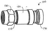
도 1은 본 발명의 실시예에 다른 전기 커넥터의 사시도이다.
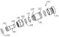
도 2는 도 1에 도시된 전기 커넥터의 분해 사시도이다.
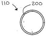
도 3a 및 도 3b는 도 1에 도시된 전기 커넥터의 접지 부재의 정면도 및 단면도이다.
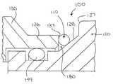
도 4는 도 1에 도시된 전기 커넥터의 부분 단면도이다.
도 5는 접지 부재의 위치를 보여주는, 도 4와 유사한 확대된 단면도이다.A more complete understanding of the invention and its advantages will be more readily obtained by reference to the following detailed description in conjunction with the following figures.
1 is a perspective view of an electrical connector according to an embodiment of the present invention.
FIG. 2 is an exploded perspective view of the electrical connector shown in FIG. 1.
3A and 3B are front and sectional views of the ground member of the electrical connector shown in FIG.
4 is a partial cross-sectional view of the electrical connector shown in FIG. 1.
5 is an enlarged cross-sectional view similar to FIG. 4 showing the position of the grounding member.
도 1, 도 2, 도 3a, 도 3b, 도 4 및 도 5에서, 본 발명은 커넥터(100)에 결합된 케이블과 텔레비전과 같은 디바이스의 상응하는 상대측 커넥터 또는 포트(도시되지 않음) 사이의 연속 접지 경로를 그 사이의 접속이 풀린다할지라도 보장하는 접지 부재(110)를 포함하는, 동축 커넥터와 같은, 전기 커넥터(100)에 관한 것이다.1, 2, 3A, 3B, 4, and 5, the present invention relates to a continuous connection between a cable coupled to
커넥터(100)는 일반적으로 접지 부재(110), 커넥터 본체(120), 결합 부재(130), 및 포스트 부재(140)를 포함하고 있다. 압축 링(170)이 이러한 커넥터와의 케이블의 단말처리를 용이하도록 하기 위해 제공될 수 있다. 도 3a 및 도 3b에 도시된 접지 부재(110)가 결합 부재(130)와 커넥터 본체(120) 사이의 전기 접촉을 유지하기 위해 커넥터(100)의 외측에 배치되어 있다. 접지 부재(110)로 인해 이러한 전기 접촉은 커넥터(100)와 그 상대측 커넥터 또는 포트 사이의 접속이 풀린다고 할지라도 유지될 것이다.The
포스트 부재(140)는 당업계에 주지된 바와 같이, 결합 부재(130)와 결합되도록 구성된 하나의 단부(146)에서 확대된 어깨부(142)를 구비한 실질상 튜브형상부, 및 동축 케이블(도시되지 않음)의 준비된 단부와 인터페이싱하도록 설계된 반대 단부(144)를 갖고 있다. 포스트 부재(140)는 도 1에 도시된 바와 같이, 커넥터 본체(120)와 결합 부재(130)내에 수용되어서 결합 부재(130)는 단부(146)에서 포스트 부재(140)에 대해 회전하고, 커넥터 본체(120)는 포스트 부재(140)와 밀착 또는 마찰 끼워맞추어져 맞물린다.
결합 부재(130)는 도 1 및 도 2에 가장 잘 도시된 바와 같이, 암나사(132)를 갖는 너트이고, 상대측 커넥터 또는 포트의 수나사와 맞물리도록 구성되는 것이 바람직하다. 결합 부재(130)는 상대측 커넥터와 맞물리는 인터페이스 단부(134)와 단부 대향면 표면(137)(도 5)을 구비한 반대 자유 단부(136)를 포함하고 있다. 결합 부재(130)의 자유 단부(136) 근방에는 포스트 부재(140)의 확대된 어깨부(142)를 잡아 결합 부재(130)를 포스트 부재(140)에 회전 결합시키는 내부로 뻗은 어깨부(138)가 존재한다. O-링(139)이 습기 이동을 방지하기 위해 결합 부재(130)의 내측에 제공되는 것이 바람직하다.
도 1 및 도 2에 도시된 바와 같이, 커넥터 본체(120)는 당업계에 주지된 바와 같이, 케이블의 준비된 단부와 결합하도록 구성된 제1 단부(122) 및 포스트 부재(140)와 맞물리는 반대반향의 테이퍼된 제2 단부(124)를 구비한 대략 튜브형상을 갖고 있다. 그 제2 단부(124)에서, 커넥터 본체(120)는 트랜지션 어깨부(127)와 테이퍼된 표면(128)을 가질 수 있는 트랜지션부(126)를 포함할 수 있다. 대안으로, 트랜지션부(126)는 테이퍼된 표면만을 가질 수 있거나 일련의 테이퍼된 어깨부일 수 있다. 트랜지션부(126)는 도 1에 도시된 바와 같이, 결합 부재(130)의 자유 단부(136)와 만난다. 갭(180)은 도 5에 도시된 바와 같이, 커넥터 본체(120)의 트랜지션부와 결합 부재(130)의 단부 대향면 표면(137) 사이에 존재한다. 갭(180)은 커넥터에서의 공차로 인해 변할 수 있다. O-링(149)이 결합 부재(130)의 자유 단부(136)의 오버랩과 커넥터 본체(120)의 제2 단부(124) 사이에 제공되어 습기 이동을 방지할 수 있다.As shown in FIGS. 1 and 2, the
도 2, 도 3a 및 도 3b에 도시된 바와 같이, 접지 부재(110)는 커넥터 본체(120)와 결합 너트(130) 위에 밀착 끼워맞춤을 형성하기 위해 탄성을 갖는 링인 것이 바람직하다. 예를 들어, 접지 부재(110)는 스프링 코일, 웨이브와셔, 스타 와셔등일 수 있다. 대안으로, 접지 부재(110)는 도전성 O-링일 수 있다. 접지 부재(110)는 커넥터(100) 위에 접지 부재(110)의 조립을 용이하게 하기 위해 절개부(200)(도 3a)를 포함할 수 있다. 도 4 및 도 5에 도시된 바와 같이, 접지 부재(110)는 결합 부재(130)의 자유단부(136)와 커넥터 본체(120)의 제2 단부(124) 사이의 갭(180)에 안착되는 것이 바람직하다. 특히, 접지 부재(110)는 구성요소의 인접면과 접촉할 수 있는데, 즉, 커넥터 본체의 제2 단부(124)의 트랜지션부(126)과 결합 부재의 자유 단부(136)의 단부 표면과 접촉한다. 접지 부재(110)가 탄성을 갖고 있기 때문에, 정위치에 있게 되고 커넥터 본체(120)와 결합 부재(130) 사이에 일정한 접지 경로를 제공할 것이다. 접지 부재(110)가 갭(180)에 위치되는 것이 바람직하지만, 접지 부재가 양측 구성요소간 전기 연속성을 유지하도록 양측 구성요소의 인접면과 접촉하는 한 커넥터 본체(120)와 결합 부재(130)의 임의의 외부 또는 노출된 표면에 위치될 수 있다.As shown in Figures 2, 3A and 3B, the
특정 실시예가 본 발명을 설명하기 위해 선택되었지만, 당업자는 첨부된 청구범위에 한정된 본 발명의 범위로부터 벗어남 없이 다양한 변경 및 수정이 가능할 수 있다는 것을 이해할 것이다.While specific embodiments have been selected to illustrate the invention, those skilled in the art will understand that various changes and modifications may be possible without departing from the scope of the invention as defined in the appended claims.
Claims (17)
Translated fromKorean상대측 커넥터와 인터페이싱하도록 구성된 인터페이스 단부 및 상기 커넥터 본체의 상기 제2 단부에서 상기 커넥터 본체에 대해 회전가능한, 상기 인터페이스 단부 반대방향의 자유 단부를 갖고 있는 결합 부재; 및
상기 커넥터 본체의 상기 제2 단부의 외표면과 상기 결합 부재의 상기 자유 단부 사이에 배치된 탄성 접지 부재를 포함하고 있으며,
상기 커넥터 본체, 상기 결합 부재 및 상기 탄성 접지 부재의 각각이 도전성을 가짐으로써 상기 커넥터 본체와 상기 결합 부재 사이에 접지 경로를 생성하는 것을 특징으로 하는 전기 커넥터.A connector body having opposite first and second ends, the first end configured to engage the prepared end of the cable;
A coupling member having an interface end configured to interface with a mating connector and a free end opposite the interface end that is rotatable relative to the connector body at the second end of the connector body; And
An elastic ground member disposed between an outer surface of the second end of the connector body and the free end of the engagement member,
And wherein each of the connector body, the coupling member, and the elastic ground member is conductive to create a ground path between the connector body and the coupling member.
상기 결합 부재는 상기 포스트 부재의 단부에 회전 결합되어 있는 것을 특징으로 하는 전기 커넥터.Further comprising a post member insertable into the connector body for engaging the prepared end of the cable,
And the coupling member is rotatably coupled to an end of the post member.
상대측 커넥터와 인터페이싱하도록 구성된 인터페이스 단부 및 상기 커넥터 본체의 상기 제2 단부에서 상기 커넥터 본체에 대해 회전가능한, 상기 인터페이스 단부 반대방향의 자유 단부를 갖고 있는 결합 부재; 및
상기 커넥터 본체의 상기 제2 단부의 외표면과 상기 결합 부재의 상기 자유 단부의 외표면 사이에 배치되어서, 탄성 접지 부재의 어떤 부분도 상기 커넥터 본체 또는 상기 결합 부재의 어느 것의 내측에 위치되지 않는 상기 탄성 접지 부재를 포함하고 있으며,
상기 커넥터 본체, 상기 결합 부재 및 상기 탄성 접지 부재의 각각이 도전성을 가짐으로써 상기 커넥터 본체와 상기 결합 부재 사이에 접지 경로를 생성하는 것을 특징으로 하는 전기 커넥터.A connector body having opposite first and second ends, the first end configured to engage the prepared end of the cable;
A coupling member having an interface end configured to interface with a mating connector and a free end opposite the interface end that is rotatable relative to the connector body at the second end of the connector body; And
Disposed between an outer surface of the second end of the connector body and an outer surface of the free end of the engagement member such that no part of the resilient grounding member is located inside of the connector body or any of the engagement member; It includes an elastic ground member,
And wherein each of the connector body, the coupling member, and the elastic ground member is conductive to create a ground path between the connector body and the coupling member.
상대측 커넥터와 인터페이싱하도록 구성된 인터페이스 단부 및 상기 커넥터 본체의 상기 제2 단부에서 상기 커넥터 본체에 대해 회전가능한, 상기 인터페이스 단부 반대방향의 자유 단부를 갖고 있는 결합 부재; 및
상기 커넥터 본체의 상기 제2 단부와 상기 결합 부재의 상기 자유 단부 사이에 위치되어 있고, 상기 커넥터 본체와 상기 결합 부재 사이에 접지 경로를 제공하는 접지 부재를 포함하는 것을 특징으로 하는 전기 커넥터.A connector body having opposite first and second ends, the first end configured to engage the prepared end of the cable;
A coupling member having an interface end configured to interface with a mating connector and a free end opposite the interface end that is rotatable relative to the connector body at the second end of the connector body; And
And a grounding member located between the second end of the connector body and the free end of the coupling member and providing a ground path between the connector body and the coupling member.
Applications Claiming Priority (3)
| Application Number | Priority Date | Filing Date | Title |
|---|---|---|---|
| US40892710P | 2010-11-01 | 2010-11-01 | |
| US61/408,927 | 2010-11-01 | ||
| PCT/US2011/058777WO2012061379A2 (en) | 2010-11-01 | 2011-11-01 | Electrical connector with grounding member |
Publications (1)
| Publication Number | Publication Date |
|---|---|
| KR20130127457Atrue KR20130127457A (en) | 2013-11-22 |
Family
ID=46025061
Family Applications (1)
| Application Number | Title | Priority Date | Filing Date |
|---|---|---|---|
| KR1020137012497AWithdrawnKR20130127457A (en) | 2010-11-01 | 2011-11-01 | Electrical connector with grounding member |
Country Status (10)
| Country | Link |
|---|---|
| US (3) | US20120135639A1 (en) |
| EP (1) | EP2636105B1 (en) |
| JP (1) | JP2013541821A (en) |
| KR (1) | KR20130127457A (en) |
| AU (1) | AU2011323526B2 (en) |
| BR (1) | BR112013010925B1 (en) |
| CA (1) | CA2816561C (en) |
| DK (1) | DK2636105T3 (en) |
| MX (1) | MX2013004718A (en) |
| WO (1) | WO2012061379A2 (en) |
Families Citing this family (54)
| Publication number | Priority date | Publication date | Assignee | Title |
|---|---|---|---|---|
| US7114990B2 (en) | 2005-01-25 | 2006-10-03 | Corning Gilbert Incorporated | Coaxial cable connector with grounding member |
| US8113875B2 (en) | 2008-09-30 | 2012-02-14 | Belden Inc. | Cable connector |
| US8573996B2 (en) | 2009-05-22 | 2013-11-05 | Ppc Broadband, Inc. | Coaxial cable connector having electrical continuity member |
| US8287320B2 (en) | 2009-05-22 | 2012-10-16 | John Mezzalingua Associates, Inc. | Coaxial cable connector having electrical continuity member |
| US9017101B2 (en) | 2011-03-30 | 2015-04-28 | Ppc Broadband, Inc. | Continuity maintaining biasing member |
| US9570845B2 (en) | 2009-05-22 | 2017-02-14 | Ppc Broadband, Inc. | Connector having a continuity member operable in a radial direction |
| US8444445B2 (en) | 2009-05-22 | 2013-05-21 | Ppc Broadband, Inc. | Coaxial cable connector having electrical continuity member |
| TWI549386B (en) | 2010-04-13 | 2016-09-11 | 康寧吉伯特公司 | Coaxial connector with inhibited ingress and improved grounding |
| US8888526B2 (en)* | 2010-08-10 | 2014-11-18 | Corning Gilbert, Inc. | Coaxial cable connector with radio frequency interference and grounding shield |
| TWI558022B (en) | 2010-10-27 | 2016-11-11 | 康寧吉伯特公司 | Push-on cable connector with a coupler and retention and release mechanism |
| US20140051285A1 (en)* | 2010-11-01 | 2014-02-20 | Amphenol Corporation | Electrical connector with integrated grounding member and gripping sleeve |
| KR20130127457A (en)* | 2010-11-01 | 2013-11-22 | 암페놀 코포레이션 | Electrical connector with grounding member |
| US8337229B2 (en) | 2010-11-11 | 2012-12-25 | John Mezzalingua Associates, Inc. | Connector having a nut-body continuity element and method of use thereof |
| US8376769B2 (en)* | 2010-11-18 | 2013-02-19 | Holland Electronics, Llc | Coaxial connector with enhanced shielding |
| US8414322B2 (en) | 2010-12-14 | 2013-04-09 | Ppc Broadband, Inc. | Push-on CATV port terminator |
| US8398421B2 (en) | 2011-02-01 | 2013-03-19 | John Mezzalingua Associates, Inc. | Connector having a dielectric seal and method of use thereof |
| US8157588B1 (en) | 2011-02-08 | 2012-04-17 | Belden Inc. | Cable connector with biasing element |
| US8465322B2 (en) | 2011-03-25 | 2013-06-18 | Ppc Broadband, Inc. | Coaxial cable connector |
| US8366481B2 (en) | 2011-03-30 | 2013-02-05 | John Mezzalingua Associates, Inc. | Continuity maintaining biasing member |
| US8388377B2 (en) | 2011-04-01 | 2013-03-05 | John Mezzalingua Associates, Inc. | Slide actuated coaxial cable connector |
| US9711917B2 (en) | 2011-05-26 | 2017-07-18 | Ppc Broadband, Inc. | Band spring continuity member for coaxial cable connector |
| US9203167B2 (en) | 2011-05-26 | 2015-12-01 | Ppc Broadband, Inc. | Coaxial cable connector with conductive seal |
| US8758050B2 (en) | 2011-06-10 | 2014-06-24 | Hiscock & Barclay LLP | Connector having a coupling member for locking onto a port and maintaining electrical continuity |
| US8591244B2 (en) | 2011-07-08 | 2013-11-26 | Ppc Broadband, Inc. | Cable connector |
| US9190744B2 (en) | 2011-09-14 | 2015-11-17 | Corning Optical Communications Rf Llc | Coaxial cable connector with radio frequency interference and grounding shield |
| US20130072057A1 (en) | 2011-09-15 | 2013-03-21 | Donald Andrew Burris | Coaxial cable connector with integral radio frequency interference and grounding shield |
| US8777661B2 (en) | 2011-11-23 | 2014-07-15 | Holland Electronics, Llc | Coaxial connector having a spring with tynes deflectable by a mating connector |
| US9028276B2 (en) | 2011-12-06 | 2015-05-12 | Pct International, Inc. | Coaxial cable continuity device |
| US8968025B2 (en)* | 2011-12-27 | 2015-03-03 | Glen David Shaw | Coupling continuity connector |
| US9190773B2 (en)* | 2011-12-27 | 2015-11-17 | Perfectvision Manufacturing, Inc. | Socketed nut coaxial connectors with radial grounding systems for enhanced continuity |
| US8636541B2 (en)* | 2011-12-27 | 2014-01-28 | Perfectvision Manufacturing, Inc. | Enhanced coaxial connector continuity |
| US9136654B2 (en) | 2012-01-05 | 2015-09-15 | Corning Gilbert, Inc. | Quick mount connector for a coaxial cable |
| US9407016B2 (en) | 2012-02-22 | 2016-08-02 | Corning Optical Communications Rf Llc | Coaxial cable connector with integral continuity contacting portion |
| US9287659B2 (en) | 2012-10-16 | 2016-03-15 | Corning Optical Communications Rf Llc | Coaxial cable connector with integral RFI protection |
| US9147963B2 (en) | 2012-11-29 | 2015-09-29 | Corning Gilbert Inc. | Hardline coaxial connector with a locking ferrule |
| TWM451726U (en)* | 2012-12-07 | 2013-04-21 | Yueh-Chiung Lu | Leaning type continuous coaxial cable connector |
| US9153911B2 (en) | 2013-02-19 | 2015-10-06 | Corning Gilbert Inc. | Coaxial cable continuity connector |
| US9172154B2 (en) | 2013-03-15 | 2015-10-27 | Corning Gilbert Inc. | Coaxial cable connector with integral RFI protection |
| US10290958B2 (en) | 2013-04-29 | 2019-05-14 | Corning Optical Communications Rf Llc | Coaxial cable connector with integral RFI protection and biasing ring |
| CN105284015B (en) | 2013-05-20 | 2019-03-08 | 康宁光电通信Rf有限责任公司 | Coaxial cable connector with whole RFI protection |
| US9548557B2 (en) | 2013-06-26 | 2017-01-17 | Corning Optical Communications LLC | Connector assemblies and methods of manufacture |
| US9048599B2 (en) | 2013-10-28 | 2015-06-02 | Corning Gilbert Inc. | Coaxial cable connector having a gripping member with a notch and disposed inside a shell |
| US9197008B1 (en)* | 2014-08-26 | 2015-11-24 | Tyco Electronics Corporation | Electrical assembly having a threaded coupling nut and retaining ring |
| WO2016073309A1 (en) | 2014-11-03 | 2016-05-12 | Corning Optical Communications Rf Llc | Coaxial cable connector with integral rfi protection |
| US9590287B2 (en) | 2015-02-20 | 2017-03-07 | Corning Optical Communications Rf Llc | Surge protected coaxial termination |
| US10033122B2 (en) | 2015-02-20 | 2018-07-24 | Corning Optical Communications Rf Llc | Cable or conduit connector with jacket retention feature |
| US10211547B2 (en) | 2015-09-03 | 2019-02-19 | Corning Optical Communications Rf Llc | Coaxial cable connector |
| US9525220B1 (en) | 2015-11-25 | 2016-12-20 | Corning Optical Communications LLC | Coaxial cable connector |
| US20170152975A1 (en)* | 2015-11-30 | 2017-06-01 | Yi-Chuan Huang | Rotatable connector for connecting a fluid transmission pipe |
| US10218094B2 (en) | 2016-01-15 | 2019-02-26 | Ppc Broadband, Inc. | Connectors having a cable gripping portion |
| US10439302B2 (en) | 2017-06-08 | 2019-10-08 | Pct International, Inc. | Connecting device for connecting and grounding coaxial cable connectors |
| US20190074610A1 (en)* | 2017-09-01 | 2019-03-07 | Amphenol Corporation | Coaxial cable connector with grounding coupling nut |
| CA3107916A1 (en)* | 2018-07-17 | 2020-01-23 | Ppc Broadband, Inc. | Coaxial cable connector |
| US12034264B2 (en) | 2021-03-31 | 2024-07-09 | Corning Optical Communications Rf Llc | Coaxial cable connector assemblies with outer conductor engagement features and methods for using the same |
Family Cites Families (59)
| Publication number | Priority date | Publication date | Assignee | Title |
|---|---|---|---|---|
| DE1490385C3 (en) | 1963-03-18 | 1975-04-30 | Siemens Ag, 1000 Berlin Und 8000 Muenchen | Cable connector with connector housing for coaxial high-frequency cables |
| US3336563A (en) | 1964-04-13 | 1967-08-15 | Amphenol Corp | Coaxial connectors |
| US3783178A (en)* | 1972-08-03 | 1974-01-01 | Gen Signal Corp | Expansion joint for connecting rigid conduit with grounding continuity |
| US4525017A (en) | 1983-05-11 | 1985-06-25 | Allied Corporation | Anti-decoupling mechanism for an electrical connector assembly |
| US4557546A (en) | 1983-08-18 | 1985-12-10 | Sealectro Corporation | Solderless coaxial connector |
| US5021001A (en) | 1987-01-29 | 1991-06-04 | Lucas Weinschel Inc. | Multiple use electrical connector having planar exposed surface |
| USRE33611E (en)* | 1988-07-01 | 1991-06-11 | Molex Incorporated | Environmentally sealed grounding backshell with strain relief |
| WO1990009926A2 (en) | 1989-03-03 | 1990-09-07 | Fbi Brands Ltd. | Packaging perishable liquids in gable top cartons |
| JP2735306B2 (en) | 1989-08-17 | 1998-04-02 | 株式会社東芝 | Substrate cooling device |
| JPH0635410Y2 (en)* | 1989-09-13 | 1994-09-14 | 宇呂電子工業株式会社 | Coaxial plug |
| US5137471A (en) | 1990-07-06 | 1992-08-11 | Amphenol Corporation | Modular plug connector and method of assembly |
| JP3074864B2 (en) | 1991-11-22 | 2000-08-07 | 大日本インキ化学工業株式会社 | Coloring material and resin composition containing the same |
| DE4206092C1 (en) | 1992-02-27 | 1993-07-01 | Spinner Gmbh Elektrotechnische Fabrik, 8000 Muenchen, De | |
| JPH06275345A (en) | 1992-11-05 | 1994-09-30 | Waka Seisakusho:Kk | High-frequency coaxial connector |
| JP3160835B2 (en) | 1993-12-21 | 2001-04-25 | 株式会社小糸製作所 | Vehicle sign lights |
| US5683263A (en) | 1996-12-03 | 1997-11-04 | Hsu; Cheng-Sheng | Coaxial cable connector with electromagnetic interference and radio frequency interference elimination |
| US6146208A (en) | 1997-06-17 | 2000-11-14 | Commscope | Field connector adaptor |
| US6153830A (en) | 1997-08-02 | 2000-11-28 | John Mezzalingua Associates, Inc. | Connector and method of operation |
| US6231357B1 (en) | 1998-01-20 | 2001-05-15 | Relight America, Inc. | Waterproof high voltage connector |
| US6217383B1 (en) | 2000-06-21 | 2001-04-17 | Holland Electronics, Llc | Coaxial cable connector |
| JP4503793B2 (en)* | 2000-06-30 | 2010-07-14 | 日本アンテナ株式会社 | Coaxial plug |
| JP3488422B2 (en) | 2000-09-05 | 2004-01-19 | 日本アンテナ株式会社 | Rotating coaxial plug |
| US6716062B1 (en) | 2002-10-21 | 2004-04-06 | John Mezzalingua Associates, Inc. | Coaxial cable F connector with improved RFI sealing |
| US6712631B1 (en) | 2002-12-04 | 2004-03-30 | Timothy L. Youtsey | Internally locking coaxial connector |
| US7029305B2 (en) | 2003-09-03 | 2006-04-18 | Tyco Electronics Corporation | Coaxial connector with torque limiting control |
| US7002077B2 (en) | 2004-03-01 | 2006-02-21 | Thomas & Betts International, Inc. | Threadless conduit fitting including continuous compression ring |
| DE102004017659A1 (en) | 2004-04-05 | 2005-10-27 | Biotronik Vi Patent Ag | Spring contact element |
| US20060110977A1 (en) | 2004-11-24 | 2006-05-25 | Roger Matthews | Connector having conductive member and method of use thereof |
| US8157589B2 (en) | 2004-11-24 | 2012-04-17 | John Mezzalingua Associates, Inc. | Connector having a conductively coated member and method of use thereof |
| US8071174B2 (en) | 2009-04-03 | 2011-12-06 | John Mezzalingua Associates, Inc. | Conductive elastomer and method of applying a conductive coating to elastomeric substrate |
| US7114990B2 (en) | 2005-01-25 | 2006-10-03 | Corning Gilbert Incorporated | Coaxial cable connector with grounding member |
| US7131867B1 (en) | 2005-05-06 | 2006-11-07 | Pacific Aerospace & Electronics, Inc. | RF connectors having ground springs |
| US7097499B1 (en)* | 2005-08-18 | 2006-08-29 | John Mezzalingua Associates, Inc. | Coaxial cable connector having conductive engagement element and method of use thereof |
| US7222889B2 (en) | 2005-08-23 | 2007-05-29 | Stanley Aviation Corporation | Self-locking self-bonding rigid coupling |
| US7179121B1 (en) | 2005-09-23 | 2007-02-20 | Corning Gilbert Inc. | Coaxial cable connector |
| US7306484B1 (en)* | 2006-06-26 | 2007-12-11 | Scientific-Atlanta, Inc. | Coax-to-power adapter |
| US8062044B2 (en) | 2006-10-26 | 2011-11-22 | John Mezzalingua Associates, Inc. | CATV port terminator with contact-enhancing ground insert |
| US20080102696A1 (en) | 2006-10-26 | 2008-05-01 | John Mezzalingua Associates, Inc. | Flexible rf seal for coax cable connector |
| US7758367B2 (en)* | 2007-01-08 | 2010-07-20 | Thomas & Betts International, Inc. | Hollow ring seating indicator |
| US7566236B2 (en) | 2007-06-14 | 2009-07-28 | Thomas & Betts International, Inc. | Constant force coaxial cable connector |
| CN201113063Y (en) | 2007-10-27 | 2008-09-10 | 贵州航天电器股份有限公司 | High-low temperature resistant and low-permeability sealed radio frequency coaxial electric connector |
| JPWO2009066705A1 (en) | 2007-11-19 | 2011-04-07 | マスプロ電工株式会社 | Coaxial cable connector |
| US8113875B2 (en) | 2008-09-30 | 2012-02-14 | Belden Inc. | Cable connector |
| US7635283B1 (en) | 2008-11-24 | 2009-12-22 | Andrew Llc | Connector with retaining ring for coaxial cable and associated methods |
| US8025518B2 (en) | 2009-02-24 | 2011-09-27 | Corning Gilbert Inc. | Coaxial connector with dual-grip nut |
| US8029315B2 (en)* | 2009-04-01 | 2011-10-04 | John Mezzalingua Associates, Inc. | Coaxial cable connector with improved physical and RF sealing |
| US7824216B2 (en)* | 2009-04-02 | 2010-11-02 | John Mezzalingua Associates, Inc. | Coaxial cable continuity connector |
| US7674132B1 (en)* | 2009-04-23 | 2010-03-09 | Ezconn Corporation | Electrical connector ensuring effective grounding contact |
| US8287320B2 (en) | 2009-05-22 | 2012-10-16 | John Mezzalingua Associates, Inc. | Coaxial cable connector having electrical continuity member |
| US8444445B2 (en) | 2009-05-22 | 2013-05-21 | Ppc Broadband, Inc. | Coaxial cable connector having electrical continuity member |
| US8573996B2 (en) | 2009-05-22 | 2013-11-05 | Ppc Broadband, Inc. | Coaxial cable connector having electrical continuity member |
| US8272893B2 (en) | 2009-11-16 | 2012-09-25 | Corning Gilbert Inc. | Integrally conductive and shielded coaxial cable connector |
| KR100972031B1 (en) | 2010-02-16 | 2010-07-22 | 김영숙 | Connecter for fixing cable |
| TWI549386B (en) | 2010-04-13 | 2016-09-11 | 康寧吉伯特公司 | Coaxial connector with inhibited ingress and improved grounding |
| US7892024B1 (en) | 2010-04-16 | 2011-02-22 | Ezconn Corporation | Coaxial cable connector |
| US8167636B1 (en) | 2010-10-15 | 2012-05-01 | John Mezzalingua Associates, Inc. | Connector having a continuity member |
| KR20130127457A (en)* | 2010-11-01 | 2013-11-22 | 암페놀 코포레이션 | Electrical connector with grounding member |
| US8337229B2 (en) | 2010-11-11 | 2012-12-25 | John Mezzalingua Associates, Inc. | Connector having a nut-body continuity element and method of use thereof |
| US8376769B2 (en) | 2010-11-18 | 2013-02-19 | Holland Electronics, Llc | Coaxial connector with enhanced shielding |
- 2011
- 2011-11-01KRKR1020137012497Apatent/KR20130127457A/ennot_activeWithdrawn
- 2011-11-01USUS13/286,570patent/US20120135639A1/ennot_activeAbandoned
- 2011-11-01BRBR112013010925-4Apatent/BR112013010925B1/enactiveIP Right Grant
- 2011-11-01WOPCT/US2011/058777patent/WO2012061379A2/enactiveApplication Filing
- 2011-11-01CACA2816561Apatent/CA2816561C/enactiveActive
- 2011-11-01JPJP2013536925Apatent/JP2013541821A/enactivePending
- 2011-11-01EPEP11838673.9Apatent/EP2636105B1/enactiveActive
- 2011-11-01DKDK11838673.9Tpatent/DK2636105T3/enactive
- 2011-11-01MXMX2013004718Apatent/MX2013004718A/enactiveIP Right Grant
- 2011-11-01AUAU2011323526Apatent/AU2011323526B2/enactiveActive
- 2012
- 2012-02-07USUS13/368,047patent/US8231412B2/enactiveActive
- 2012-06-22USUS13/530,831patent/US8808019B2/enactiveActive
Also Published As
| Publication number | Publication date |
|---|---|
| US8808019B2 (en) | 2014-08-19 |
| JP2013541821A (en) | 2013-11-14 |
| US20120264332A1 (en) | 2012-10-18 |
| US20120142217A1 (en) | 2012-06-07 |
| AU2011323526A1 (en) | 2013-05-30 |
| EP2636105A4 (en) | 2014-12-03 |
| US8231412B2 (en) | 2012-07-31 |
| US20120135639A1 (en) | 2012-05-31 |
| BR112013010925B1 (en) | 2021-03-23 |
| AU2011323526B2 (en) | 2016-07-07 |
| WO2012061379A3 (en) | 2012-07-19 |
| MX2013004718A (en) | 2013-08-29 |
| CA2816561A1 (en) | 2012-05-10 |
| EP2636105A2 (en) | 2013-09-11 |
| BR112013010925A2 (en) | 2016-08-23 |
| EP2636105B1 (en) | 2017-05-03 |
| DK2636105T3 (en) | 2017-08-21 |
| CA2816561C (en) | 2019-10-22 |
| WO2012061379A2 (en) | 2012-05-10 |
Similar Documents
| Publication | Publication Date | Title |
|---|---|---|
| KR20130127457A (en) | Electrical connector with grounding member | |
| TWI596845B (en) | Electrical connector and apparatus thereof | |
| TWI542089B (en) | Coaxial cable connector with integral radio frequency interference and grounding shield | |
| TWI558022B (en) | Push-on cable connector with a coupler and retention and release mechanism | |
| US8591244B2 (en) | Cable connector | |
| TW201906257A (en) | Connection device for connecting and grounding coaxial cable connectors | |
| US20140051285A1 (en) | Electrical connector with integrated grounding member and gripping sleeve | |
| US12249800B2 (en) | High frequency electrical connector | |
| JP6517615B2 (en) | Electrical connector | |
| TW201214895A (en) | Coaxial cable connector with radio frequency interference and grounding shield | |
| CA2965885C (en) | Twist-lock electrical connector | |
| TW201316627A (en) | Coaxial cable connector with radio frequency interference and grounding shield | |
| TW200703824A (en) | Electrical connector with grounding member | |
| US10320110B2 (en) | Plug-in connector | |
| CA2763743A1 (en) | Connection device for a solar module | |
| US9362671B2 (en) | Coaxial cable connector with quick-locking connection | |
| CN110011137B (en) | Electrical plug-in connector | |
| KR20140019244A (en) | Latching device for thin wire to board connector | |
| EP3111514B1 (en) | Improved device for the ground connection of coaxial cables | |
| WO2015039076A1 (en) | Electrical connector with integrated grounding member and gripping sleeve | |
| TW201843891A (en) | Electrical connector | |
| KR20000017587U (en) | Connector housings for shielding connectors from electromagnetic field | |
| CN109698424A (en) | Connector assembly and female connectors | |
| TWM487555U (en) | Electrical connection device |
Legal Events
| Date | Code | Title | Description |
|---|---|---|---|
| PA0105 | International application | Patent event date:20130515 Patent event code:PA01051R01D Comment text:International Patent Application | |
| PG1501 | Laying open of application | ||
| PC1203 | Withdrawal of no request for examination | ||
| WITN | Application deemed withdrawn, e.g. because no request for examination was filed or no examination fee was paid |