KR20130127442A - Bone implant - Google Patents
Bone implantDownload PDFInfo
- Publication number
- KR20130127442A KR20130127442AKR1020137009966AKR20137009966AKR20130127442AKR 20130127442 AKR20130127442 AKR 20130127442AKR 1020137009966 AKR1020137009966 AKR 1020137009966AKR 20137009966 AKR20137009966 AKR 20137009966AKR 20130127442 AKR20130127442 AKR 20130127442A
- Authority
- KR
- South Korea
- Prior art keywords
- bone
- shaft
- implant
- anchoring element
- spherical head
- Prior art date
- Legal status (The legal status is an assumption and is not a legal conclusion. Google has not performed a legal analysis and makes no representation as to the accuracy of the status listed.)
- Granted
Links
Images


Classifications
- A—HUMAN NECESSITIES
- A61—MEDICAL OR VETERINARY SCIENCE; HYGIENE
- A61B—DIAGNOSIS; SURGERY; IDENTIFICATION
- A61B17/00—Surgical instruments, devices or methods
- A61B17/56—Surgical instruments or methods for treatment of bones or joints; Devices specially adapted therefor
- A61B17/58—Surgical instruments or methods for treatment of bones or joints; Devices specially adapted therefor for osteosynthesis, e.g. bone plates, screws or setting implements
- A61B17/68—Internal fixation devices, including fasteners and spinal fixators, even if a part thereof projects from the skin
- A61B17/74—Devices for the head or neck or trochanter of the femur
- A61B17/742—Devices for the head or neck or trochanter of the femur having one or more longitudinal elements oriented along or parallel to the axis of the neck
- A61B17/746—Devices for the head or neck or trochanter of the femur having one or more longitudinal elements oriented along or parallel to the axis of the neck the longitudinal elements coupled to a plate opposite the femoral head
- A—HUMAN NECESSITIES
- A61—MEDICAL OR VETERINARY SCIENCE; HYGIENE
- A61B—DIAGNOSIS; SURGERY; IDENTIFICATION
- A61B17/00—Surgical instruments, devices or methods
- A61B17/56—Surgical instruments or methods for treatment of bones or joints; Devices specially adapted therefor
- A61B17/58—Surgical instruments or methods for treatment of bones or joints; Devices specially adapted therefor for osteosynthesis, e.g. bone plates, screws or setting implements
- A61B17/68—Internal fixation devices, including fasteners and spinal fixators, even if a part thereof projects from the skin
- A61B17/72—Intramedullary devices, e.g. pins or nails
- A—HUMAN NECESSITIES
- A61—MEDICAL OR VETERINARY SCIENCE; HYGIENE
- A61B—DIAGNOSIS; SURGERY; IDENTIFICATION
- A61B17/00—Surgical instruments, devices or methods
- A61B17/56—Surgical instruments or methods for treatment of bones or joints; Devices specially adapted therefor
- A61B17/58—Surgical instruments or methods for treatment of bones or joints; Devices specially adapted therefor for osteosynthesis, e.g. bone plates, screws or setting implements
- A61B17/68—Internal fixation devices, including fasteners and spinal fixators, even if a part thereof projects from the skin
- A61B17/74—Devices for the head or neck or trochanter of the femur
- A61B17/742—Devices for the head or neck or trochanter of the femur having one or more longitudinal elements oriented along or parallel to the axis of the neck
- A61B17/744—Devices for the head or neck or trochanter of the femur having one or more longitudinal elements oriented along or parallel to the axis of the neck the longitudinal elements coupled to an intramedullary nail
- A—HUMAN NECESSITIES
- A61—MEDICAL OR VETERINARY SCIENCE; HYGIENE
- A61B—DIAGNOSIS; SURGERY; IDENTIFICATION
- A61B17/00—Surgical instruments, devices or methods
- A61B17/56—Surgical instruments or methods for treatment of bones or joints; Devices specially adapted therefor
- A61B17/58—Surgical instruments or methods for treatment of bones or joints; Devices specially adapted therefor for osteosynthesis, e.g. bone plates, screws or setting implements
- A61B17/68—Internal fixation devices, including fasteners and spinal fixators, even if a part thereof projects from the skin
- A61B17/74—Devices for the head or neck or trochanter of the femur
- A61B17/742—Devices for the head or neck or trochanter of the femur having one or more longitudinal elements oriented along or parallel to the axis of the neck
- A61B17/748—Devices for the head or neck or trochanter of the femur having one or more longitudinal elements oriented along or parallel to the axis of the neck with means for adapting the angle between the longitudinal elements and the shaft axis of the femur
- A—HUMAN NECESSITIES
- A61—MEDICAL OR VETERINARY SCIENCE; HYGIENE
- A61B—DIAGNOSIS; SURGERY; IDENTIFICATION
- A61B17/00—Surgical instruments, devices or methods
- A61B17/56—Surgical instruments or methods for treatment of bones or joints; Devices specially adapted therefor
- A61B17/58—Surgical instruments or methods for treatment of bones or joints; Devices specially adapted therefor for osteosynthesis, e.g. bone plates, screws or setting implements
- A61B17/68—Internal fixation devices, including fasteners and spinal fixators, even if a part thereof projects from the skin
- A61B17/80—Cortical plates, i.e. bone plates; Instruments for holding or positioning cortical plates, or for compressing bones attached to cortical plates
- A—HUMAN NECESSITIES
- A61—MEDICAL OR VETERINARY SCIENCE; HYGIENE
- A61B—DIAGNOSIS; SURGERY; IDENTIFICATION
- A61B17/00—Surgical instruments, devices or methods
- A61B17/56—Surgical instruments or methods for treatment of bones or joints; Devices specially adapted therefor
- A61B17/58—Surgical instruments or methods for treatment of bones or joints; Devices specially adapted therefor for osteosynthesis, e.g. bone plates, screws or setting implements
- A61B17/68—Internal fixation devices, including fasteners and spinal fixators, even if a part thereof projects from the skin
- A61B17/84—Fasteners therefor or fasteners being internal fixation devices
- A61B17/86—Pins or screws or threaded wires; nuts therefor
Landscapes
- Health & Medical Sciences (AREA)
- Orthopedic Medicine & Surgery (AREA)
- Surgery (AREA)
- Life Sciences & Earth Sciences (AREA)
- Heart & Thoracic Surgery (AREA)
- Nuclear Medicine, Radiotherapy & Molecular Imaging (AREA)
- Engineering & Computer Science (AREA)
- Biomedical Technology (AREA)
- Neurology (AREA)
- Medical Informatics (AREA)
- Molecular Biology (AREA)
- Animal Behavior & Ethology (AREA)
- General Health & Medical Sciences (AREA)
- Public Health (AREA)
- Veterinary Medicine (AREA)
- Surgical Instruments (AREA)
- Prostheses (AREA)
Abstract
Translated fromKoreanDescription
Translated fromKorean우선권 주장Priority claim
본 출원은 “뼈 임플란트(Bone Implant)”라는 명칭으로, 로버트 프리그(Robert Frigg)에 의해 2010년 10월 27일자로 출원된 미국 가출원 제61/407,231호에 대한 우선권을 주장한다. 가출원 명세서의 그 전문은 여기에 참조로서 삽입된다.This application claims priority to U.S. Provisional Application No. 61 / 407,231, filed October 27, 2010, by Robert Frigg entitled " Bone Implant ". The full text of which is incorporated herein by reference.
본 발명은 일반적으로 골절을 치료하는 장치에 관한 것이다. 특히, 본 발명은 뼈의 골단(뼈끝; epiphyseal) 부분에서의 골절을 치료하기 위하여 뼈 플레이트(bone plate) 또는 골수내 네일(intramedullary nail)에 사용될 수 있는 고정 요소를 포함하는 장치에 관한 것이다.The present invention generally relates to an apparatus for treating fractures. In particular, the present invention relates to an apparatus comprising a fixation element that can be used in a bone plate or an intramedullary nail to treat fractures in the epiphyseal part of the bone.
긴 뼈의 골단 부분에서의 골절은 대퇴경부 나사(femoral neck screw)와 같은 대퇴 임플란트로 치료될 수 있다. 이러한 대퇴경부 나사는 뼈 플레이트 또는 골수내 네일에 결합되어, 경부 나사가 뼈 플레이트 또는 골수내 네일에 대하여 축 방향으로 전위될 수 있어 대퇴경부 나사의 축 방향으로의 역동화(dynamization)를 가능하게 하고, 대퇴경부 나사와 뼈 플레이트 또는 골수내 내일 사이의 각도 안정성(angular stability)을 제공한다.Fractures in the proximal portion of the long bone can be treated with a femoral implant, such as a femoral neck screw. This femoral neck screw is attached to a bone plate or bone marrow nail so that the neck screw can be displaced axially with respect to the bone plate or bone marrow nail to enable axially dynamization of the femoral neck screw , Angular stability between the femoral neck screw and the bone plate or within the bone marrow.
그러나, 골절이 제대로 감소되지 않은 일부의 경우, 대퇴경부 나사의 이식(implantation)은 단지 뼈의 골절된 부위 사이의 한정된 접촉 영역에서 일어날 수 있다. 대퇴경부 나사를 통한 역동화는, 예를 들어 두개의 골절의 오정렬로 인하여 불충분하거나 부적절한 골절 감소를 종종 보상하지 못한다. 불충분한 골절 접촉 영역은 골절 치료를 지연시킬 수 있고, 결국 대퇴 헤드(femoral head) 내 나사 정착의 주기적인 과부하(cyclic overload)로 이어질 수 있다. 주기적인 과부하는 임플란트 헐거움 및/또는 임플란트 절단을 야기할 수 있다. 수술 동안에 시상면(saggital plane)에서의 골절 위치의 시각화가 매우 어렵기 때문에, 불출분한 골절 감소는 종종 시상면에서 발생한다. 헤드 단편(head fragment)의 회전은 나사의 잘못된 위치로 인한 임플란트 절단의 위험을 증가시킬 수 있다.However, in some cases where the fracture has not been adequately reduced, implantation of the femoral neck screw may only occur in confined contact areas between the fractured parts of the bone. Inversion through the femoral neck screw often fails to compensate for insufficient or inadequate fracture reduction, for example due to misalignment of the two fractures. Inadequate fracture contact areas can delay the treatment of fractures and eventually lead to cyclic overload of screw fixation in the femoral head. Periodic overloading can result in implant loosening and / or implant shear. Because visualization of the fracture site in the saggital plane during surgery is very difficult, a reduction in non-operative fracture often occurs in the sagittal plane. Rotation of the head fragment can increase the risk of implant removal due to misalignment of the screw.
본 발명은 중심축을 따라 제1단으로부터 제2단까지 연장하고, 최대 반경(r)을 갖는 축 및 상기 축의 제1단에 부착되고, 반경(R>r)을 갖는 구형 헤드 요소(spherical head element)를 포함하는 골단 고정 요소(epiphyseal fixation element)를 포함하는 뼈 임플란트에 관한 것이다. 뼈 임플란트는 축의 제2단이 슬라이딩 가능하게 맞물릴 수 있는 뼈 플레이트 또는 골수내 네일을 더 포함한다. 이 뼈 임플란트는 근위(proximal) 및 원위(distal) 대퇴골(femur) 모두, 근위 하퇴골(tibia) 및 상박골(humerus)을 위해서 사용될 수 있다.The present invention relates to a spherical head element having an axis extending along a central axis from a first end to a second end and having an axis with a maximum radius r and a first end attached to the axis and having a radius R & The present invention relates to a bone implant comprising an epiphyseal fixation element. The bone implant further comprises a bone plate or bone marrow nail to which the second end of the shaft is slidably engageable. These bone implants can be used for both proximal and distal femurs, proximal tibia, and humerus.
본 발명에 따른 뼈 임플란트의 일부 이점은, 고정 요소의 구형 헤드 요소가 골단 단편, 예를 들어 대퇴부 헤드가 구형 헤드 요소의 중심에 대하여 회전(pivot) 가능하게 하며, 따라서 불충분한 골절 감소의 부분적인 보상을 가능하게 하고, 그리고 세로방향 축과 뼈 플레이트 또는 골수내 네일 사이의 슬라이딩 가능한 구성과 더불어 골단 단편, 예를 들어 대퇴 헤드의 회전 가능한 고정은 골절 갭이 닫힐 때까지 골단 단편을 회전하고 축방향으로 이동시킨다는 점이다. 따라서, 골절 안정성은 두 골절 사이의 보다 큰 뼈 접촉 영역 전반에 걸친 물리적 하중의 분포로 인하여 향상된다.A partial advantage of the bone implant according to the invention is that the spherical head element of the fixation element enables the golfer segment, e.g. the femoral head, to pivot about the center of the spherical head element, The rotatable fixation of the femoral fragment, e.g. the femoral head, with the slidable configuration between the longitudinal axis and the bone plate or bone marrow nail enabling compensation, rotates the bone fragment until the fracture gap is closed, . Thus, fracture stability is improved due to the distribution of physical loads across the larger bone contact area between the two fractures.
뼈 임플란트의 일 예시적인 실시예에서, 반경 비(r/R)는 적어도 0.65, 바람직하게는 적어도 0.7이다.In one exemplary embodiment of a bone implant, the radius ratio (r / R) is at least 0.65, preferably at least 0.7.
뼈 임플란트의 다른 예시적인 실시예에서, 반경 비(r/R)는 최대 0.9, 바람직하게는 최대 0.8이다. 대퇴경부 골절을 위하여, 이러한 반경 비는 정상적인 조건 하에서, 대퇴부 헤드가 중심축에 대하여 -15°∼ -20° 사이에서 +15°∼ +20°사이까지의 각도 범위 내에서 구형 헤드 요소의 중심 둘레를 회전 가능하게 한다.In another exemplary embodiment of a bone implant, the radius ratio r / R is at most 0.9, preferably at most 0.8. For a femoral neck fracture, this radius ratio must be such that, under normal conditions, the femoral head is positioned within the angular range of -15 ° to + 20 ° with respect to the central axis between + 15 ° and + 20 °, .
뼈 임플란트의 또 다른 예시적인 실시예에서, 축은 원통형이다.In another exemplary embodiment of a bone implant, the shaft is cylindrical.
뼈 임플란트의 또 다른 예시적인 실시예에서, 축은 하나 이상의 소성 변형가능한 연결 요소를 갖는 조인트를 통하여 뼈 플레이트 또는 골수내 네일에 연결되어, 슬리브를 뼈 플레이트 또는 골수내 네일에, 바람직하게는 카르단(cardan) 조인트를 통하여 회전 가능하게 연결한다. 이 구성은 골단 단편이 골단 고정 요소의 중심축을 가로지르는 방향으로 변위될(displaced) 수 있도록 축이 경사질(tilt) 수 있다는 장점이 있다.In another exemplary embodiment of a bone implant, the shaft is connected to a bone plate or an intramedullary nail via a joint having at least one plastically deformable connecting element, the sleeve being attached to a bone plate or bone marrow nail, cardan joints. This configuration has the advantage that the shaft can be tilted so that the golfer segment is displaced in a direction transverse to the center axis of the golfer fixation element.
뼈 임플란트의 다른 예시적인 실시예에서, 세로방향 축 및 구형 헤드 요소는 케뉼러 배관된다(cannulated).In another exemplary embodiment of a bone implant, the longitudinal axis and the spherical head element are cannulated.
본 발명의 다른 견지에 따르면, 뼈 임플란트는 제1단으로부터 제2단까지 중심축을 따라 연장하고, 최대 반경(r)을 갖는 세로방향 축 및 상기 축의 제1단에 이동가능하게 결합되고, 세로방향 축의 직경보다 큰 외경을 갖는 뼈 앵커링 요소(bone anchoring element)를 포함한다. 상기 임플란트는 축의 제2단이 슬라이딩 가능하게 맞물릴 수 있는 뼈 플레이트 또는 골수내 네일을 더 포함한다.According to a further aspect of the present invention, a bone implant comprises a longitudinal axis extending along a central axis from a first end to a second end and having a maximum radius r and a distal end movably coupled to the first end of the axis, And a bone anchoring element having an outer diameter greater than the diameter of the shaft. The implant further comprises a bone plate or bone marrow nail to which the second end of the shaft is slidably engageable.
본 발명의 예시적인 실시예에 따른 뼈 임플란트의 일부 이점은, 뼈 앵커링 요소 및 고정 요소의 세로방향 축 사이의 관절 결합은 골단 단편, 예를 들어 대퇴 헤드가 회전하여 불충분한 골절 감소의 적어도 부분적인 보상을 가능하게 하고, 골단 단편 예를 들어 대퇴 헤드의 회전 가능한 고정은 앵커링 요소의 임플란트의 세로방향 축의 축방향 슬라이딩 가능한 구성과 더불어, 골절 갭이 닫힐 때까지 골단 단편이 회전 및/또는 축방향으로 변위하도록 하는 것이다. 따라서, 골절 안정성은 두 단편 사이의 보다 큰 뼈 접촉 영역에 걸친 물리적 하중의 분포로 인하여 향상된다.A partial advantage of a bone implant according to an exemplary embodiment of the present invention is that the articulation between the longitudinal axis of the bone anchoring element and the anchoring element causes the bone fragment, e.g., the femoral head, to rotate at least partially And the rotatable fixation of the femoral head, for example, of the femoral head, with the axially slidable configuration of the longitudinal axis of the implant of the anchoring element, allows the femoral section to rotate and / or axially move until the fracture gap is closed To be displaced. Thus, fracture stability is improved due to the distribution of physical loads across the larger bone contact area between the two fragments.
뼈 임플란트의 일 예시적인 실시예에서, 뼈 앵커링 요소는 볼-소켓(ball-and-socket) 조인트를 통하여 축의 제1단에 결합된다.In one exemplary embodiment of a bone implant, the bone anchoring element is coupled to the first end of the shaft through a ball-and-socket joint.
뼈 임플란트의 다른 예시적인 실시예에서, 뼈 앵커링 요소는 카르단 조인트를 통하여 축의 제1단에 결합된다.In another exemplary embodiment of a bone implant, the bone anchoring element is coupled to the first end of the shaft through a cardan joint.
뼈 임플란트의 또 다른 예시적인 실시예에서, 뼈 앵커링 요소는 유연 부재(compliant member)를 통하여 축의 제1단에 결합된다.In another exemplary embodiment of a bone implant, the bone anchoring element is coupled to the first end of the shaft through a compliant member.
뼈 임플란트의 또 다른 예시적인 실시예에서, 유연 부재는 금속성 또는 플라스틱 벨로우(bellow)이다.In another exemplary embodiment of a bone implant, the flexible member is a metallic or plastic bellow.
뼈 임플란트의 다른 예시적인 실시예에서, 유연 부재는 금속성 또는 플라스틱 스프링이다.In another exemplary embodiment of a bone implant, the flexible member is a metallic or plastic spring.
뼈 임플란트의 다른 예시적인 실시예에서, 유연 부재는 탄성중합체를 포함한다.In another exemplary embodiment of a bone implant, the flexible member comprises an elastomer.
뼈 임플란트의 또 다른 예시적인 실시예에서, 축은 하나 이상의 가소 변형가능한 연결 요소를 갖는 조인트를 통하여 뼈 플레이트 또는 골수내 네일에 연결되어, 슬리브를 뼈 플레이트 또는 골수내 네일에, 바람직하게는 카르단 조인트를 통하여 회전가능하게 연결한다. 따라서, 본 실시예는 골단 단편이 골단 고정 요소의 중심축을 가로지르는 방향으로 변위될 수 있도록 축이 경사진다는 장점이 있다.In another exemplary embodiment of a bone implant, the shaft is connected to a bone plate or an intramedullary nail through a joint having one or more prismatically deformable connecting elements to couple the sleeve to a bone plate or bone marrow nail, As shown in Fig. Therefore, the present embodiment is advantageous in that the shaft is inclined so that the golfer segment can be displaced in the direction transverse to the center axis of the golfer fixing member.
뼈 임플란트의 또 다른 예시적인 실시예에서, 축은 원통형이다. 이 경우, 최대 반경(r)은 원형 단면의 반경과 일치한다.In another exemplary embodiment of a bone implant, the shaft is cylindrical. In this case, the maximum radius r coincides with the radius of the circular cross section.
뼈 임플란트의 또 다른 예시적인 실시예에서, 세로방향 축 및 뼈 앵커링 요소는 케뉼러 배관된다.In another exemplary embodiment of a bone implant, the longitudinal axis and bone anchoring elements are cannulated.
뼈 임플란트의 또 다른 예시적인 실시예에서, 고정 요소는 축의 일단에 고정된 또는 고정가능한 구형 헤드 요소를 포함한다. 구형 헤드 요소는 반경(R > r)을 갖고, 뼈 앵커링 요소는 회전 방식으로 구형 헤드 요소를 수용하기 위한 반경(R)을 갖는 구형 캐비티를 포함한다.In another exemplary embodiment of a bone implant, the fixation element comprises a spherical head element that is fixed or fixable to one end of the shaft. The spherical head element has a radius (R > r) and the bone anchoring element includes a spherical cavity having a radius (R) for receiving spherical head elements in a rotational manner.
뼈 임플란트의 다른 예시적인 실시예에서, 구형 헤드 요소는 케뉼러 배관된다.In another exemplary embodiment of a bone implant, the spherical head element is cannulated.
뼈 임플란트의 다른 예시적인 실시예에서, 반경 비(r/R)는 적어도 0.65, 바람직하게는 적어도 0.7이다.In another exemplary embodiment of a bone implant, the radius ratio (r / R) is at least 0.65, preferably at least 0.7.
뼈 임플란트의 다른 예시적인 실시예에서, 반경 비(r/R)는 최대 0.9, 바람직하게는 최대 0.8이다. 대퇴경부 골절에서, 이러한 반경 비는 정상적인 조건 하에서, 대퇴부 헤드가 중심축에 대하여 -15°∼ -20° 사이 내지 +15° ∼ 20°사이의 각도 범위에서 구형 헤드 요소의 중심 둘레로 회전 가능하게 한다.In another exemplary embodiment of a bone implant, the radius ratio r / R is at most 0.9, preferably at most 0.8. In a femoral neck fracture, this radius ratio is such that, under normal conditions, the femoral head is rotatable about the center of the spherical head element in an angular range between -15 [deg.] And -20 [deg.] And -15 [ do.
뼈 임플란트의 또 다른 예시적인 실시예에서, 뼈 앵커링 요소는 뼈 앵커링 요소의 외면과 구형 캐비티 사이에 위치된 테이퍼 개구부부(tapered opening)를 갖고, 테이퍼 개구부부의 직경은 구형 캐비티 쪽으로 감소한다. 테이퍼 개구부부는 세로방향 축과 뼈 앵커링 요소 사이에서 보다 큰 각형성(angulation)을 허용한다.In another exemplary embodiment of a bone implant, the bone anchoring element has a tapered opening positioned between the outer surface of the bone anchoring element and the spherical cavity, and the diameter of the tapered opening portion decreases toward the spherical cavity. The tapered openings allow greater angulation between the longitudinal axis and the bone anchoring element.
뼈 임플란트의 또 다른 예시적인 실시예에서, 구형 캐비티는 구형 헤드 요소가 구형 캐비티 내부로 물리도록(snapped) 뼈 앵커링 요소의 외면 쪽으로 점점 가늘어진다.In another exemplary embodiment of a bone implant, the spherical cavity is tapered toward the outer surface of the bone anchoring element so that the spherical head element snaps into the spherical cavity.
뼈 임플란트의 다른 예시적인 실시예에서, 구형 헤드 요소 및 구형 캐비티 각각은 서로 상응하는 평평한 표면부를 갖는다. 상응하는 평평한 표면은 뼈 앵커링 요소가 골단 고정 요소의 중심축 둘레를 회전하는 것을 방지하고, 뼈 앵커링 요소가 골단 고정 요소의 중심축을 포함하는 다양한 평면에서 구형 헤드 요소의 중심 둘레를 회전하도록 한다.In another exemplary embodiment of a bone implant, each of the spherical head element and the spherical cavity has a flat surface portion corresponding to each other. The corresponding flat surface prevents the bone anchoring element from rotating about the center axis of the golfer fixation element and allows the bone anchoring element to rotate about the center of the spherical head element in various planes including the center axis of the golfer fixation element.
뼈 임플란트의 또 다른 예시적인 실시예에서, 구형 헤드 요소 및 구형 캐비티 각각은 평평한 표면부 사이에 위치된 다수의 원형 모서리(circular edges)를 포함한다.In another exemplary embodiment of a bone implant, each of the spherical head element and the spherical cavity includes a plurality of circular edges positioned between the flat surface portions.
뼈 임플란트의 또 다른 예시적인 실시예에서, 원형 모서리는 구형 헤드 요소의 중심과 일치하는 하나의 공통 중심을 갖는다.In another exemplary embodiment of a bone implant, the circular edge has one common center coinciding with the center of the spherical head element.
뼈 임플란트의 또 다른 예시적인 실시예에서, 구형 헤드 요소 및 구형 캐비티 각각은 골단 고정 요소의 중심축에 직교하는 다각형 단면, 바람직하게는 육각형 단면을 갖는다.In another exemplary embodiment of a bone implant, each of the spherical head element and the spherical cavity has a polygonal cross section, preferably a hexagonal cross section, perpendicular to the central axis of the golfer fixation element.
뼈 임플란트의 또 다른 예시적인 실시예에서, 뼈 앵커링 요소는 외부 나사산을 포함한다.In another exemplary embodiment of a bone implant, the bone anchoring element comprises an external thread.
뼈 임플란트의 또 다른 예시적인 실시예에서, 뼈 앵커링 요소는 뼈 내에 고정을 위한 블레이드(blade), 교차 블레이드 및 나선형 블레이드 중 하나를 포함한다.In another exemplary embodiment of a bone implant, the bone anchoring element includes one of a blade, a crossover blade, and a helical blade for fixation within the bone.
뼈 임플란트의 또 다른 예시적인 실시예에서, 뼈 앵커링 요소는 세로방향 축의 중심축에 대하여 동축으로 배열되지 않는다.In another exemplary embodiment of a bone implant, the bone anchoring elements are not coaxially arranged with respect to the central axis of the longitudinal axis.
본 발명의 또 다른 예시적인 실시예에 따르면, 뼈 임플란트는 근위부(proximal portion)로부터 원위부(distal portion)까지 중심축을 따라 연장하고, 최대 반경(r)을 갖는 골단 고정 요소 및 세로방향 축의 원위부에 이동가능하게 결합되고, 세로방향 축의 직경보다 큰 직경을 갖는 뼈 앵커링 요소를 포함한다. 뼈 임플란트는 세로방향 축의 근위부를 슬라이딩 가능하게 수용하는 중심 보어(central bore)를 포함하는 슬리브를 포함하고, 축의 근위부 및 슬리브는 뼈 나사를 수용하기 위한 하나 이상의 가로방향 보어를 포함한다.According to another exemplary embodiment of the present invention, a bone implant extends along a central axis from a proximal portion to a distal portion, and has a phalanx fixation element with a maximum radius r and a distal And includes a bone anchoring element having a diameter greater than the diameter of the longitudinal axis. The bone implant includes a sleeve including a central bore slidably receiving a proximal portion of the longitudinal axis, and the proximal portion of the shaft and the sleeve include one or more transverse bores for receiving bone screws.
본 발명의 예시적인 실시예에 따른 뼈 임플란트의 일부 장점은, 고정 요소의 세로방향 축에 대한 뼈 앵커링 요소의 관절 연결이 골단 단편, 예를 들어 대퇴부 헤드가 회전하여 뼈 임플란트가 불충분한 골절 감소를 부분적으로 보상할 수 있게 한다는 것이다. 또한, 임플란트에서 골단 단편, 예를 들어 대퇴부 헤드의 회전 가능한 고정은 임플란트의 세로방향 축에 대한 뼈 앵커링 요소의 축방향으로 슬라이딩 가능한 구성과 더불어 골절 갭이 닫힐 때까지 골단 단편이 회전 그리고 축방향으로 변위하도록 한다. 따라서, 골절 안정성은 두 단편 사이의 보다 큰 뼈 접촉 영역에 걸친 물리적 하중의 분포로 인하여 향상된다.Some advantages of a bone implant according to an exemplary embodiment of the present invention are that the articulation of the bone anchoring element with respect to the longitudinal axis of the anchoring element results in the reduction of the bone fragment, e.g., an insufficient fracture reduction of the bone implant, And to compensate in part. In addition, the rotatable fixation of the bone fragment, e. G., The femoral head, in the implant, along with the axial slidable configuration of the bone anchoring element relative to the longitudinal axis of the implant, To be displaced. Thus, fracture stability is improved due to the distribution of physical loads across the larger bone contact area between the two fragments.
뼈 임플란트의 일 예시적인 실시예에서, 뼈 앵커링 요소는 볼-소켓 조인트를 통하여 축의 제1단에 결합된다.In one exemplary embodiment of a bone implant, the bone anchoring element is coupled to the first end of the shaft through a ball-and-socket joint.
뼈 임플란트의 다른 예시적인 실시예에서, 뼈 앵커링 요소는 카르단 조인트를 통하여 축의 제1단에 결합된다.In another exemplary embodiment of a bone implant, the bone anchoring element is coupled to the first end of the shaft through a cardan joint.
뼈 임플란트의 다른 예시적인 실시예에서, 뼈 앵커링 요소는 유연 부재를 통하여 축의 제1단에 결합된다.In another exemplary embodiment of a bone implant, the bone anchoring element is coupled to the first end of the shaft through a flexible member.
뼈 임플란트의 다른 예시적인 실시예에서, 유연 부재는 금속성 또는 플라스틱 벨로우이다.In another exemplary embodiment of a bone implant, the flexible member is a metallic or plastic bellows.
뼈 임플란트의 또 다른 예시적인 실시예에서, 유연 부재는 금속성 또는 플라스틱 스프링이다.In another exemplary embodiment of a bone implant, the flexible member is a metallic or plastic spring.
뼈 임플란트의 또 다른 예시적인 실시예에서, 유연 부재는 탄성중합체이다.In another exemplary embodiment of a bone implant, the flexible member is an elastomer.
뼈 임플란트의 또 다른 예시적인 실시예에서, 축은 원통형이다. 본 실시예에서, 최대 반경(r)은 원형 단면의 반경과 일치한다.In another exemplary embodiment of a bone implant, the shaft is cylindrical. In this embodiment, the maximum radius r coincides with the radius of the circular cross section.
뼈 임플란트의 다른 예시적인 실시예에서, 세로방향 축 및 뼈 앵커링 요소는 케뉼러 배관된다.In another exemplary embodiment of a bone implant, the longitudinal axis and bone anchoring elements are cannulated.
뼈 임플란트의 또 다른 예시적인 실시예에서, 고정 요소는 세로방향 축의 전단부 상에 슬라이딩 가능하게 배열된 구형 헤드를 포함하고, 뼈 앵커링 요소는 회전 방식으로 구형 헤드 요소를 수용하기 위한 반경(R)을 갖는 구형 캐비티를 포함한다.In another exemplary embodiment of a bone implant, the fixation element comprises a spherical head slidably arranged on the front end of the longitudinal axis, the bone anchoring element having a radius R for accommodating the spherical head element in a rotational manner, Lt; / RTI >
본 발명의 또 다른 예시적인 실시예에서, 뼈 임플란트는 하나 이상의 가소성 변형가능한 연결 요소를 갖는 조인트 및 축을 수용하기 위한 내부 슬리브를 포함하고, 조인트는 내부 슬리브를 슬리브에 바람직하게는 카르단 조인트를 통하여 회전 가능하게 연결시킨다. 따라서, 골단 단편이 골단 고정 요소의 중심축을 가로지르는 방향으로 변위될 수 있도록 축은 경사지도록 구성된다.In another exemplary embodiment of the present invention, a bone implant includes a joint having at least one fictitiously deformable connecting element and an inner sleeve for receiving a shaft, the joint being configured to couple the inner sleeve to the sleeve, preferably through a cardan joint Rotatably. Therefore, the shaft is configured to be inclined such that the golfer segment can be displaced in the direction transverse to the center axis of the golfer fixing element.
뼈 임플란트의 또 다른 예시적인 실시예에서, 구형 헤드 요소는 케뉼러 배관된다.In another exemplary embodiment of a bone implant, the spherical head element is cannulated.
뼈 임플란트의 또 다른 예시적인 실시예에서, 반경 비(r/R)는 적어도 0.65, 바람직하게는 적어도 0.7이다.In another exemplary embodiment of a bone implant, the radius ratio (r / R) is at least 0.65, preferably at least 0.7.
뼈 임플란트의 다른 예시적인 실시예에서, 반경 비(r/R)는 최대 0.9, 바람직하게는 최대 0.8이다. 두하 상박 골절(subcapital hemeral fracture)에서, 이러한 반경 비는 정상적인 조건 하에서, 상박 헤드 단편이 중심축에 대하여 -15°∼ -20°사이 내지 +15°∼ 20°사이의 각도 범위 내에서 구형 헤드 요소의 중심 둘레를 회전 가능하게 한다.In another exemplary embodiment of a bone implant, the radius ratio r / R is at most 0.9, preferably at most 0.8. In a subcapital hemorrhage fracture, this radius ratio is such that, under normal conditions, the upper head segment is displaced in the angular range of between -15 [deg.] And -20 [deg.] To +15 [ As shown in Fig.
뼈 임플란트의 다른 예시적인 실시예에서, 뼈 앵커링 요소는 뼈 앵커링 요소의 외면과 구형 캐비티 사이에 위치된 테이퍼 개구부부를 갖고, 테이퍼 개구부부의 직경은 구형 캐비티 쪽으로 감소하여, 세로방향 축과 뼈 앵커링 요소 사이에 보다 큰 각형성을 허용한다.In another exemplary embodiment of a bone implant, the bone anchoring element has a tapered aperture portion positioned between the outer surface of the bone anchoring element and the spherical cavity, the diameter of the tapered aperture portion decreasing toward the spherical cavity, such that the longitudinal axis and the bone anchoring <Lt; RTI ID = 0.0 > a < / RTI >
뼈 임플란트의 또 다른 예시적인 실시예에서, 구형 캐비티는 구형 헤드 요소가 구형 캐비티 내부로 믈리도록 뼈 앵커링 요소의 외면 쪽으로 점점 가늘어진다.In another exemplary embodiment of a bone implant, the spherical cavity is tapered toward the outer surface of the bone anchoring element such that the spherical head element is forced into the spherical cavity.
뼈 임플란트의 또 다른 예시적인 실시예에서, 구형 헤드 요소 및 구형 캐비티 각각은 서로 상응하는 평평한 표면부를 포함하고, 상응하는 평평한 표면은 뼈 앵커링 요소가 골단 고정 요소의 중심축 둘레를 회전하는 것을 방지하고, 뼈 앵커링 요소가 골단 고정 요소의 중심축을 포함하는 다양한 평면에서 구형 헤드 요소의 중심 둘레를 회전하도록 허용한다.In another exemplary embodiment of a bone implant, each of the spherical head element and the spherical cavity includes a corresponding flat surface portion, the corresponding flat surface preventing the bone anchoring element from rotating about the center axis of the golfer fixation element , Allowing the bone anchoring element to rotate about the center of the spherical head element in various planes including the center axis of the golfer fixation element.
뼈 임플란트의 또 다른 예시적인 실시예에서, 구형 헤드 요소 및 구형 캐비티 각각은 평평한 표면부 사이에 위치된 다수의 원형 모서리를 포함한다.In another exemplary embodiment of a bone implant, each of the spherical head element and the spherical cavity includes a plurality of circular edges positioned between the flat surface portions.
뼈 임플란트의 또 다른 예시적인 실시예에서, 원형 모서리는 구형 헤드 요소의 중심 및 구형 캐비티의 중심과 일치하는 하나의 공통 중심을 갖는다.In another exemplary embodiment of a bone implant, the circular edge has a common center that coincides with the center of the spherical head element and the center of the spherical cavity.
뼈 임플란트의 또 다른 예시적인 실시예에서, 구형 헤드 요소 및 구형 캐비티 각각은 골단 고정 요소의 중심축에 직교하는 다각형 단면, 바람직하게는 육각형 단면을 갖는다.In another exemplary embodiment of a bone implant, each of the spherical head element and the spherical cavity has a polygonal cross section, preferably a hexagonal cross section, perpendicular to the central axis of the golfer fixation element.
뼈 임플란트의 또 다른 예시적인 실시예에서, 뼈 앵커링 요소는 외부 나사산을 포함한다.In another exemplary embodiment of a bone implant, the bone anchoring element comprises an external thread.
뼈 임플란트의 또 다른 예시적인 실시예에서, 뼈 앵커링 요소는 뼈 내에 고정을 위한 블레이드, 교차 블레이드 및 나선형 블레이드 중 하나를 포함한다.In another exemplary embodiment of a bone implant, the bone anchoring element comprises one of a blade, an intersecting blade and a helical blade for fixation within the bone.
뼈 임플란트의 또 다른 예시적인 실시예에서, 뼈 앵커링 요소는 세로방향 축의 중심축에 대하여 동축으로 배열되지 않는다.In another exemplary embodiment of a bone implant, the bone anchoring elements are not coaxially arranged with respect to the central axis of the longitudinal axis.
본 발명의 또 다른 예시적인 실시예에 따르면, 뼈 임플란트를 이용하여 골단 뼈 골절을 치료하는 방법은 다음 단계를 포함한다:According to another exemplary embodiment of the present invention, a method of treating a golgi bone fracture using a bone implant comprises the following steps:
a) 긴 뼈(long Bone)의 축에 대하여 사선으로(obliquely) 가이드 와이어(guide wire)를 긴 뼈에 배치시키고, 긴 뼈의 축 단편(shaft fragment)을 통하여 그리고 골단 단편 내부로 관통시키는 단계;a) obliquely arranging a guide wire in a long bone with respect to an axis of a long bone, passing through a shaft fragment of a long bone and into the bone fragment;
b) 삽입 시, 구형 헤드 요소 또는 뼈 앵커링 요소가 원하는 위치에서 골단 뼈 골절을 위한 회전 중심을 제공하도록, 긴 뼈의 외측면으로부터 긴 뼈 내부로 보어 홀(bore hole)을 뚫고 구형 헤드 요소 또는 뼈 앵커링 요소를 수용하는 단계, 여기서 보어 홀은 드릴 비트를 위한 가이드로서 가이드 와이어를 이용하여 천공되고; 및b) Upon insertion, a spherical head element or bone anchoring element is drilled through the bore hole from the outer side of the long bone to the inside of the long bone to provide the center of rotation for the alveolar bone fracture at the desired location, Receiving an anchoring element, wherein the bore hole is drilled using a guide wire as a guide for the drill bit; And
c) 구형 헤드 요소 또는 뼈 앵커링 요소가 골단 뼈 골절의 원하는 회전 중심을 제공할 때까지 보어 홀 내부로 골단 고정 요소를 삽입하는 단계.c) inserting the golfer fixing element into the borehole until the spherical head element or bone anchoring element provides the desired center of rotation of the alveolar bone fracture.
보어 홀의 방향 및 깊이는, 골단 뼈 골절의 회전 중심이 뼈 단편 내의 원하는 위치에 배치될 수 있게 구형 헤드 요소 또는 앵커링 요소가 삽입되도록, 하나 이상의 X-선 이미지를 이용하여 결정될 수 있다.The orientation and depth of the borehole may be determined using one or more X-ray images such that the spherical head element or anchoring element is inserted such that the center of rotation of the epiphyseal bone fracture may be positioned at a desired location within the bone fragment.
상기 방법의 일 실시예에서, 방법은 단계 a)를 수행하기 전에, 치료될 긴 뼈의 골수강(medullar cavity) 내부로 골수내 네일을 삽입하는 단계를 포함한다.In one embodiment of the method, the method comprises inserting an intramedullary nail into the medullar cavity of the long bone to be treated, prior to performing step a).
다른 예시적 실시예에서, 방법은 단계 c)를 수행한 후에, 뼈 플레이트가 긴 뼈의 외측면에 인접할 때까지 세로방향 축 상으로 배럴을 슬라이딩시킴으로써 뼈 플레이트를 위치시키는 단계 및 하나 이상의 뼈 나사를 이용하여 긴 뼈에 뼈 플레이트를 고정하는 단계를 포함한다.In another exemplary embodiment, the method includes the steps of positioning the bone plate by sliding the barrel on a longitudinal axis until the bone plate is adjacent the outer side of the long bone after performing step c) To fix the bone plate to the long bone.
또 다른 실시예에서, 방법은 단계 c)를 수행한 후, 슬리브가 긴 뼈 내부로 완전히 삽입될 때까지 세로방향 축 상으로 슬리브를 슬라이딩시킴으로써 보어 홀 내에 슬리브를 위치시키는 단계 및 하나 이상의 뼈 나사를 이용하여 긴 뼈에 슬리브 및 세로방향 축의 후면부를 고정하는 단계를 포함한다.In yet another embodiment, the method comprises the steps of placing the sleeve in the borehole after performing step c), by sliding the sleeve onto the longitudinal axis until the sleeve is fully inserted into the long bone, Thereby securing the sleeve and the rear portion of the longitudinal axis to the long bone.
다른 예시적인 실시예에서, 방법은 단계 c)를 수행한 후, 슬리브와 뼈 플레이트 또는 골수내 네일 사이의 가소성 변형가능한 회전 핀(pivot pins)을 포함하는 조인트를 통하여, 골단 고정 요소를 수용하고, 이어서 뼈 플레이트 또는 골수내 네일에 결합되는 슬리브에 결합된 레버(lever)를 이용하여 골절을 재-배치하는 단계를 포함한다.In another exemplary embodiment, the method comprises the steps of, after performing step c), receiving the golfer anchoring element through a joint comprising plastically deformable pivot pins between the sleeve and the bone plate or marrow nail, And then re-positioning the fracture using a lever coupled to a bone plate or sleeve coupled to the bone marrow nail.
본 발명에 따른 뼈 임플란트의 이점은, 고정 요소의 구형 헤드 요소가 골단 단편, 예를 들어 대퇴부 헤드가 구형 헤드 요소의 중심에 대하여 회전(pivot) 가능하게 하며, 따라서 불충분한 골절 감소의 부분적인 보상을 가능하게 하고, 그리고 세로방향 축과 뼈 플레이트 또는 골수내 네일 사이의 슬라이딩 가능한 구성과 더불어 골단 단편, 예를 들어 대퇴 헤드의 회전 가능한 고정은 골절 갭이 닫힐 때까지 골단 단편을 회전하고 축방향으로 이동시킨다는 점이다. 따라서, 골절 안정성은 두 골절 사이의 보다 큰 뼈 접촉 영역 전반에 걸친 물리적 하중의 분포로 인하여 향상된다.An advantage of a bone implant according to the present invention is that the spherical head element of the stationary element enables the golfer segment, e.g. the femoral head, to pivot about the center of the spherical head element, And the rotatable fixation of the femoral fragment, e.g. the femoral head, with the slidable configuration between the longitudinal axis and the bone plate or bone marrow nail, rotates the femoral section until the fracture gap is closed, . Thus, fracture stability is improved due to the distribution of physical loads across the larger bone contact area between the two fractures.
본 발명의 몇몇 실시예가 예시적으로 첨부된 도면을 참조하여 설명된다;
도 1은 본 발명에 따른 뼈 임플란트의 일 실시예의 측면도를 보여주며;
도 2는 구형 헤드 요소 둘레를 회전하는 대퇴부 헤드 단편을 갖는 도 1의 뼈 임플란트의 일 실시예의 측면도를 보여주며;
도 3은 본 발명에 따른 뼈 임플란트의 다른 실시예의 측면도를 보여주며;
도 4는 회전된 대퇴부 헤드 및 닫힌 골절 갭을 갖는 도 3의 뼈 임플란트의 일 실시예의 측면도를 보여주며;
도 5는 도 3의 뼈 임플란트의 일 실시예의 평면도를 보여주며;
도 6은 회전된 대퇴부 헤드 및 닫힌 골절 갭을 갖는 도 3의 뼈 임플란트의 일 실시예의 평면도를 보여주며;
도 7은 본 발명에 따른 뼈 임플란트의 다른 실시예의 측면도를 보여주며;
도 8은 도 3의 일 실시예의 고정 요소 및 삽입 툴의 확대도를 보여주며;
도 9는 삽입 툴과 더불어 도 3의 일 실시예의 고정 요소를 통한 종단면도를 보여주며;
도 10은 본 발명에 따른 뼈 임플란트의 또 다른 실시예의 고정 요소를 통한 종단면도를 보여주며;
도 11은 본 발명에 따른 뼈 임플란트의 다른 실시예의 앵커링 요소의 측면도를 보여주며;
도 12는 도 11에 나타낸 A 방향으로 보여진 도 11의 앵커링 요소의 정면도를 보여주며;
도 13은 본 발명에 따른 뼈 임플란트의 또 다른 실시예의 앵커링 요소의 측면도를 보여주며;
도 14는 도 13에 나타난 B 방향으로 보여진 도 13의 앵커링 요소의 정면도를 보여주며;
도 15는 본 발명에 따른 뼈 임플란트의 또 다른 실시예의 앵커링 요소의 측면도를 보여주며;
도 16은 도 15에 나타낸 C 방향으로 보여진 도 15의 앵커링 요소의 정면도를 보여주며;
도 17은 도 3에 따른 뼈 임플란트의 일 실시예의 고정 요소를 통한 종단면도를 보여주며;
도 18은 본 발명에 따른 뼈 임플란트의 다른 실시예의 고정 요소를 통한 종단면도를 보여주며;
도 19는 본 발명에 따른 뼈 임플란트의 또 다른 실시예의 고정 요소의 측면도를 보여주며;
도 20은 본 발명에 따른 뼈 임플란트의 또 다른 실시예의 고정 요소의 측면도를 보여주며;
도 21은 본 발명에 따른 뼈 임플란트의 또 다른 실시예의 고정 요소의 측면도를 보여주며;
도 22는 본 발명에 따른 뼈 임플란트의 또 다른 실시예의 고정 요소의 측면도를 보여주며;
도 23은 두하 상박 헤드 골절(subcapital humeral head fracture) 치료의 경우 뼈 임플란트의 또 다른 실시예를 통한 종단면도를 보여주며;
도 24는 역동화 후의 골절 갭을 갖는 도 23의 뼈 임플란트의 일 실시예를 통한 종단면도를 보여주며;
도 25a 및 도 25b는 도 23에 따른 뼈 임플란트의 일 실시예의 고정 요소의 전단부를 통한 종단면도에서 최대 축방향 역동화를 보여주며;
도 26은 도 23에 따른 고정 요소의 전단부를 통한 종단면도에서 축방향 역동화 없는 최대 각형성을 보여주며;
도 27은 본 발명에 따른 뼈 임플란트의 다른 실시예의 측면도를 보여주며;
도 28은 도 27의 화살표 A 방향에 의해 보여진 도 27에 따른 뼈 임플란트의 일 실시예의 정면도를 보여주며;
도 29는 구형 헤드 요소 둘레를 회전하는 대퇴부 헤드 단편을 갖는 도 27의 뼈 임플란트의 일 실시예의 측면도를 보여주며;
도 30은 근위 방향으로 배치된 회전된 대퇴부 헤드 단편을 갖는 도 27의 뼈 임플란트의 일 실시예의 측면도를 보여주며;
도 31은 제1 비-확대 구성에서 본 발명에 따른 뼈 임플란트의 또 다른 실시예의 단면도를 보여주며;
도 32는 제2 확대 구성에서 도 31에 도시된 일 실시예의 단면도를 보여주며;
도 33은 제1 비-확대 구성에서 도 31에 도시된 뼈 임플란트의 일부의 단면도를 보여주며; 그리고
도 34은 제2 비-확대 구성에서 도 31에 도시된 뼈 임플란트의 일부의 단면도를 보여준다.Some embodiments of the invention are illustrated by way of example with reference to the accompanying drawings;
1 shows a side view of an embodiment of a bone implant according to the present invention;
Figure 2 shows a side view of one embodiment of the bone implant of Figure 1 with a femoral head piece rotating around a spherical head element;
Figure 3 shows a side view of another embodiment of a bone implant according to the present invention;
Figure 4 shows a side view of one embodiment of the bone implant of Figure 3 with a rotated femoral head and a closed fracture gap;
Figure 5 shows a top view of one embodiment of the bone implant of Figure 3;
Figure 6 shows a top view of one embodiment of the bone implant of Figure 3 with a rotated femoral head and a closed fracture gap;
Figure 7 shows a side view of another embodiment of a bone implant according to the present invention;
Figure 8 shows an enlarged view of the fastening element and insertion tool of one embodiment of Figure 3;
Figure 9 shows a longitudinal section through the anchoring element of one embodiment of Figure 3 with an insertion tool;
Figure 10 shows a longitudinal section through a fixture element of another embodiment of a bone implant according to the invention;
11 shows a side view of an anchoring element of another embodiment of a bone implant according to the present invention;
Figure 12 shows a front view of the anchoring element of Figure 11 shown in direction A shown in Figure 11;
Figure 13 shows a side view of an anchoring element of another embodiment of a bone implant according to the present invention;
Figure 14 shows a front view of the anchoring element of Figure 13 shown in direction B shown in Figure 13;
Figure 15 shows a side view of an anchoring element of another embodiment of a bone implant according to the present invention;
Figure 16 shows a front view of the anchoring element of Figure 15 shown in C direction shown in Figure 15;
Figure 17 shows a longitudinal section through the anchoring element of one embodiment of a bone implant according to Figure 3;
18 shows a longitudinal section through a fixture element of another embodiment of a bone implant according to the invention;
Figure 19 shows a side view of a fixation element of another embodiment of a bone implant according to the present invention;
Figure 20 shows a side view of a fixation element of another embodiment of a bone implant according to the present invention;
Figure 21 shows a side view of a fixation element of another embodiment of a bone implant according to the present invention;
Figure 22 shows a side view of a fixation element of another embodiment of a bone implant according to the present invention;
Figure 23 shows a longitudinal section through another embodiment of a bone implant in the treatment of subcapital humeral head fracture;
Figure 24 shows a longitudinal section through one embodiment of the bone implant of Figure 23 with a fracture gap after dynamization;
Figures 25a and 25b show maximum axial dynamics in a longitudinal section through the front end of the anchoring element of one embodiment of a bone implant according to Figure 23;
Figure 26 shows the maximum angular formation without axial dynamism in a longitudinal section through the front end of the stationary element according to Figure 23;
Figure 27 shows a side view of another embodiment of a bone implant according to the present invention;
Figure 28 shows a front view of an embodiment of a bone implant according to Figure 27 shown by the direction of arrow A in Figure 27;
Figure 29 shows a side view of one embodiment of the bone implant of Figure 27 with a femoral head piece rotating around a spherical head element;
Figure 30 shows a side view of one embodiment of the bone implant of Figure 27 with a rotated femoral head segment disposed in a proximal direction;
31 shows a cross-sectional view of another embodiment of a bone implant according to the invention in a first non-enlarged configuration;
Figure 32 shows a cross-sectional view of one embodiment shown in Figure 31 in a second enlarged configuration;
Figure 33 shows a cross-sectional view of a portion of the bone implant shown in Figure 31 in a first non-enlarged configuration; And
Figure 34 shows a cross-sectional view of a portion of the bone implant shown in Figure 31 in a second non-enlarged configuration.
본 발명은 이어지는 설명 및 첨부된 도면을 참조하여 더 이해될 수 있고, 동일한 요소는 동일한 참조 번호로 지칭된다.The invention may be better understood with reference to the following description and the appended drawings, wherein like elements are referred to by like reference numerals.
본 발명은 골절을 치료하는 장치에 관한 것이고, 특히 대퇴골과 같은 긴 뼈의 골단부(epiphyseal portion)에서의 골절을 치료하는 장치에 관한 것이다. 본 발명의 예시적인 실시예는 골절을 통한 뼈의 외측면을 경유하여 헤드부로 삽입될 뼈 플레이트 또는 골수내 네일과 같은 임플란트와 함께 사용될 수 있는 고정 요소를 설명한다. 고정 요소는 일단에서 구형부(spherical portion)를 포함하는 세로방향 축을 포함하고, 헤드 부분이 구형부 둘레를 회전 가능하게 하여 골절의 적절한 감소를 용이하게 하도록 뼈의 헤드 부분 내에 위치한다. 여기에서 사용된 바와 같이, 근위 및 원위는 장치의 사용자 쪽으로의 방향(근위) 및 사용자로부터 멀어지는 방향(원위)으로 언급된다는 것에 유의하여야 한다.The present invention relates to an apparatus for treating a fracture, and more particularly to a device for treating a fracture in an epiphyseal portion such as a femur. Exemplary embodiments of the present invention describe a fixation element that can be used with an implant, such as a bone plate or bone marrow nail, to be inserted into the head portion via the external surface of the bone through fracture. The anchoring element includes a longitudinal axis including a spherical portion at one end and is positioned within the head portion of the bone to facilitate rotation of the head portion around the spherical portion to facilitate proper reduction of the fracture. As used herein, it should be noted that the proximal and distal are referred to as the direction (proximal) towards the user of the device and the direction away from the user (distal).
도 1 및 도 2에 도시된 바와 같이, 본 발명의 예시적인 실시예에 따른 임플란트(1)는 대퇴경부 골절을 치료하기 위한 힙 나사(hip screw)로 구성된 고정 요소(2) 및 뼈 플레이트(6)를 포함한다. 고정 요소(2)는 제1 원위단(47)으로부터 제2 근위단(48)까지 중심축(17)을 따라 길이방향으로 연장하는 축(5) 및 제1단(47)에서의 구형 헤드 요소(3)를 포함한다. 구형 헤드 요소(3)는 중심(15) 및 축(5)의 직경(d)보다 큰 직경(D)을 갖는다. 구형 헤드 요소(3)는 축(5)과 일체로 형성되거나, 축(5)의 제1단(47)에 결합 가능하다. 축(5)의 직경은 구형 헤드 요소(3)의 직경(D)의 약 75%일 수 있다. 더욱이, 고정 요소(2)는 중심축(17)과 동축으로 고정 요소(2)를 통하여 연장하는 케뉼러 배관(cannulation)(21)을 또한 포함한다.1 and 2, an
뼈 플레이트(6)는 세로방향 몸체부(53) 및 몸체부(53)로부터 가로방향으로 연장하는 배럴(barrel)(23)을 포함한다. 본 실시예에 따른 몸체부(53)는 긴 뼈(4)(예를 들어, 대퇴골)에 부착될 수 있는 크기 및 형상을 갖고, 뼈에 뼈 플레이트(6)를 고정하기 위한 뼈 고정 나사(24)를 수용하도록 크기 및 형상을 갖는 개구부(opening)를 포함한다. 배럴(23)은 구형 헤드 요소(3)가 배럴(23)의 원위단을 지나 말단으로 연장하도록, 고정 요소(2)의 축(5)을 슬라이딩 가능하게 수용하는 크기 및 형상을 갖는 관통 홀(25)을 포함한다. 축(5)과 뼈 플레이트(6)의 배럴(23) 사이의 슬라이딩 가능한 배치는, 고정 요소(2)가 고정 요소(2)의 중심축(17)을 따라 뼈 플레이트(6)에 대하여 이동되게 하여, 고정 요소(2)의 중심축(17)의 방향으로 골절의 역동화를 용이하게 한다. 배럴(23)을 통하여 연장하는 고정 요소(2)는 또한 고정 요소(2)와 뼈 플레이트(6) 사이에 각도 안정성을 제공한다.The
사용에 있어서, 배럴(23)은 구형 헤드 요소(3)가 뼈 단편 내에 정확하게 위치된 후, 축(5) 상에 위치된다. 축(5)은 배럴(23) 내에서 슬라이딩 가능하며, 예를 들어, 수술 후에 이동될 수 있다. 이러한 방법으로, 뼈 단편의 감소는 원래의 골절 전 형태의 뼈로 복원하려는 근육, 중력 등의 자연적인 영향하에서 이루어진다. 고정 요소(2)는 동일한 자연적인 영향으로 인하여 수술 후 정 위치에 남을 수 있다. 그러나, 본 발명이 속하는 기술분야의 숙련자에 의해 이해될 수 있는 바와 같이, 추가적인 기능이 고정 요소(2)의 예상치 못한 또는 원치 않는 움직임을 막는데 이용될 수 있다. 예를 들어, 배럴(23)의 내경은 자연적인 영향으로 인한 움직임 이외의 움직임을 방지하는 마찰력을 제공하는 크기를 가질 수 있다. 다른 예시에서, 오-링(o-ring) 타입의 장치가 원치 않는 움직임을 방지하는데 이용될 수 있다. 본 발명이 속하는 기술분야의 숙련자에 의해 이해될 수 있는 바와 같이, 물론 다른 방법도 가능하다.In use, the
보어 홀(10)은 대퇴경부의 축에 실질적으로 동축이거나 평행하게 대퇴골의 외측면으로부터 근위 대퇴골 내부로 뚫린다. 보어 홀(10)은 구형 헤드 요소(3)가 보어 홀(10)을 통하여 대퇴부 헤드에 위치되기 적합하도록 구형 헤드 요소(3)의 직경(D)에 해당하는 직경을 갖는다. 구형 헤드 요소(3)가 보어 홀(10)의 일단에 다다르고, 대퇴부 헤드 단편이 구형 헤드 요소(3)에 안착될 때까지 고정 요소(2)는 보어 홀(10)을 통하여 근위 대퇴골 내를 진행한다. 근위 대퇴골 내의 보어 홀(10)의 직경이 축(5)의 직경(d)보다 크기 때문에, 대퇴부 헤드 단편은 소정 범위의 각도 내에서 구형 헤드 요소(3)의 중심에 대하여 다축 방향(polyaxially)으로 회전할 수 있다.The
대퇴경부 골절이 고정 요소(2)의 배치 전에 적절하기 않게 및/또는 충분하지 않게 감소되는 경우, 두 개의 뼈 단편은, 도 1에 도시된 바와 같이, 서로에 대하여 단지 제한된 접촉 영역을 가질 것이다. 단독 역동화, 즉 고정 요소(2)의 뼈 플레이트(6) 쪽으로의 동축 이동은 불충분한 골절 감소를 보상할 수 없다. 불충분한 골절 접촉 영역이 지연된 골절 치료를 야기하고 결과적으로 대퇴부 헤드 내에서 고정 요소(2)의 정착의 주기적인 과부하로 이어질 수 있다는 것을 본 발명이 속한 기술분야의 숙련자에 의해 이해될 것이다. 주기적인 과부하는 임플란트 헐거움(loosening) 및/또는 임플란트 절단을 야기할 수 있다. 시상면(saggital plane)에서의 골절 위치의 시각화가 수술 동안 매우 어렵기 때문에 불충분한 골절 감소가 종종 시상면에서 발생한다.If the femoral neck fracture is improperly and / or insufficiently reduced prior to placement of the
구형 헤드 요소(3)의 중심에 대한 대퇴부 헤드 단편의 회전은 적어도 부분적으로 불충분한 골절 감소를 보상한다. 따라서, 도 3에 도시된 바와 같이, 생리학적 하중이 뼈 단편의 보다 큰 접촉 영역에 걸쳐 분포하기 때문에, 골절 안정성은 대퇴부 헤드 단편의 축방향 역동화 및 회전 둘 모두를 통하여 향상된다.Rotation of the femoral head segment relative to the center of the
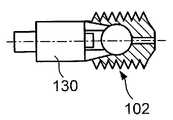
도 3 내지 도 6에 도시된 바와 같이, 본 발명의 다른 예시적인 실시예에 따른 뼈 임플란트(100)는 상술한 바와 같은 뼈 임플란트(1)와 실질적으로 유사하다. 뼈 임플란트(100)는 대퇴경부 골절을 치료하기 위한 힙 나사로 구성된 고정 요소(102) 및 뼈 플레이트(106)를 포함한다. 뼈 플레이트(106)는 뼈 플레이트(6)와 실질적으로 유사하고, 세로방향 몸체부(153) 및 이로부터 가로방향으로 연장하는 배럴(123)을 포함한다. 고정 요소(102)는 또한 고정 요소(2)와 실질적으로 유사하지만, 고정 요소(102)가 뼈의 대퇴부 헤드부에 고정될 수 있도록 세로축(105)의 제1단(147)에 결합되는 앵커링 요소(108)를 더 포함한다.3 to 6, a
고정 요소(102)는 제1단(147)으로부터 제2단(147)으로 중심축(117)을 따라 세로방향으로 연장하는 축(105) 및 제1단(147)의 구형 헤드 요소(103)를 포함한다. 구형 헤드 요소(103)는 중심(115) 및 축(105)의 직경(d)보다 더 큰 직경(D)을 갖는다. 직경(d)는 구형 헤드 요소(103)의 직경(D)의 대략 75%일 수 있다.The
고정 요소(102)는 구형 헤드 요소(103)에 결합되는 앵커링 요소(108)를 더 포함한다. 앵커링 요소(108)는 볼-소켓 조인트가 앵커링 요소(108)와 축(105) 사이에서 형성되도록 구형 헤드 요소(103)를 수용하는 크기 및 형상을 갖는 구형 캐비티(109)를 포함한다. 앵커링 요소(108)는 대퇴부 헤드 단편 내부로 나삽되도록 구성된 직경(DA)을 갖는 외부 나사산(120)을 갖는다. 또한, 고정 요소(102)는 축(105)을 통하여 연장하는 케뉼러 배관(121), 구형 헤드 요소(103) 및 중심축(117)과 동축을 이루거나 평행한 고정 요소(102)의 앵커링 요소(108)를 포함한다.The
도 1 및 도 2의 실시예와 유사하게, 보어 홀(110)은 대퇴경부의 축과 동축으로 또는 평행하게 연장하도록 대퇴골의 외측면으로부터 근위 대퇴골 내부로 뚫린다. 보어 홀(110)은 외부 나사산(120)이 대퇴부 헤드 단편의 뼈 조직으로 끼어들 수 있도록, 앵커링 요소(8)의 외부 나사산(120)의 코어 직경에 해당하는 직경을 갖는다. 따라서, 앵커링 요소(108)가 뼈 내부로 완전히 진행되면, 대퇴부 헤드 단편은 앵커링 요소(108)에 고정된다.Similar to the embodiment of Figures 1 and 2, the
고정 요소(102)는, 앵커링 요소(108)를 통하여 구형 헤드 요소(103) 상에 안착되는 대퇴부 헤드 단편과 함께 보어 홀(110)의 일단에 앵커링 요소(108)가 위치될 때까지, 근위 대퇴골 내의 보어 홀(110) 내부로 진행한다. 근위 대퇴골 내의 보어 홀(110)의 직경이 축(5)의 직경보다 크기 때문에, 대퇴부 헤드 단편은 소정 범위의 각도 내에서 구형 헤드 요소(103)의 중심에 대하여 다축 방향으로 회전할 수 있다.The anchoring
상술한 뼈 임플란트(1)에 유사하게, 고정 요소(102)의 축(105)은 뼈 플레이트(106)의 배럴부(123)의 관통 홀(125)을 통하여 슬라이딩 가능하게 수용된다. 관통 홀(125) 내에서 세로방향 축(105)의 슬라이딩 가능한 배치는, 고정 요소(102)의 중심축(117) 방향으로 골절의 역동화를 용이하게 할 뿐만 아니라, 고정 요소(102)와 뼈 플레이트(106) 사이의 각도 안정성을 용이하게 한다. 도 1과 유사하게, 도 3 및 도 5는 두 뼈 단편이 서로에 대하여 단지 제한된 접촉 영역을 갖도록 고정 요소(102)의 배치 전에 대퇴경부 골절의 적절하지 않는 및/또는 충분하지 않는 감소를 보여준다. 역동화 단독은, 즉 뼈 플레이트(106) 쪽으로의 고정 요소(102)의 동축 이동은 불충분한 골절 감소를 완벽하게 보상할 수 없다. 그러나, 도 4 및 도 6에 도시된 바와 같이, 고정 요소(102)는 구형 헤드 요소(103)의 중심에 대하여 앵커링 요소(108) 그리고, 결과적으로는 앵커링 요소(108)가 이식되는 대퇴부 헤드 단편의 회전을 허용하여, 적어도 부분적으로 불충분한 골절 감소를 보상한다. 대퇴골 헤드 단편의 회전을 수반하는 축방향 역동화는 뼈 단편의 보다 큰 접촉 영역에 걸친 생리학적 하중을 분산함으로써 불충분한 감소를 보상할 수 있다.Similar to the
도 7은 상술한 바와 같은 뼈 임플란트(100)와 실질적으로 유사한 뼈 임플란트(200)를 보여주지만, 뼈 플레이트 대신에 골수내 네일(207)의 일부를 통하여 삽입되는 고정 요소(202)를 포함한다. 고정 요소(202)는 고정 요소(102)와 실질적으로 유사하고, 일단에 구형 헤드 요소(203)을 포함하는 세로축(205) 및 대퇴골 헤드 내부로 나삽될 수 있고, 구형 헤드 요소(203)를 수용하는 구형 캐비티(209)를 갖는 앵커링 요소(208)를 포함하는, 힙 나사로서 구성된다. 본 발명이 속한 기술분야의 숙련자에 의해 이해될 수 있는 바와 같이, 축(205)은 배럴(223) 내에 슬라이딩 가능할 수 있다. 그러나 본 실시예에서, 축(205)은 배럴(223)과 일체로 형성된다. 이러한 방법으로, 고정 요소(202)는 축부(205) 및 배럴부(223)를 갖고, 축부(205)는 배럴부(223)보다 작은 직경을 갖는다. 고정 요소(202)는 골수내 네일(207)의 세로축에 대하여 가로방향으로 골수내 네일(207)을 통하여 연장하는 관통 보어(222) 내에 슬라이딩 가능하게 배열된다. 골수내 네일(207) 내의 관통 보어(222) 내에서 고정 요소(202)의 슬라이딩 가능한 배치는, 고정 요소(202)가 관통 홀(222)의 중심축에 대하여 축방향으로 이동되어 고정 요소(202)의 중심축(217)의 방향으로 골절의 역동화를 용이하게 하고, 고정 요소(202)와 골수내 네일(202) 사이의 각도 안정성을 향상시킨다. 뼈 고정 요소(102)와 유사하게, 앵커링 요소(208) 그리고 결과적으로, 앵커링 요소(208)가 이식되는 대퇴부 헤드 단편은 구형 헤드 요소(203)에 대하여 회전이 허용되어 불충분한 골절 감소를 보상한다.Figure 7 shows a
도 8 및 도 9는 대퇴부 헤드 단편 내부로 앵커링 요소(108)를 삽입하기 위한 중공 삽입 툴(hollow insertion tool)(130)을 보여준다. 그러나, 중공 삽입 툴(130)이 여기에 설명된 임의의 앵커링 요소의 삽입을 위해 사용될 수 있다는 것은 본 발명이 속한 기술분야의 숙련자에 의해 이해될 수 있을 것이다. 중공 삽입 툴(130)은, 중공 튜브(130)가 앵커링 요소(108)로 구동력(예를 들어, 회전)을 인가하는 데 이용될 수 있도록, 앵커링 요소(108)의 근위단(134)에서 실질적으로 사각형 단면을 갖는 대각적으로(diametrically) 연장하는 홈(131)과 맞물리기 위하여 원위단(133)의 돌출부(132)를 포함한다. 도 8 및 도 9에 의해 도시된 바와 같이, 홈(131)은 뼈 앵커링 요소(108)의 벽에 위치된다. 사용에 있어서, 축(105) 및 앵커링 요소(108)를 포함하는 고정 요소(102)를 삽입한 후, 삽입 툴(130)은 축(105) 상으로 슬라이딩되어 앵커링 요소(108)를 회전시킨다. 즉, 돌출부(132)는 홈(131)과 맞물리며, 삽입 툴(130)은 회전되어 앵커링 요소(108)를 뼈 단편으로 나삽시킨다. 고정 요소(102)가 뼈 앵커링 요소(108)를 통하여 연장하는 케뉼러 배관 및 세로축(105)을 포함하기 때문에, 뼈 앵커링 요소(108)가 중공 삽입 툴(130)을 이용하여 뼈 내부로 진행할 때, 뼈 앵커링 요소(108)는 가이드 요소, 예를 들어, 케이-와이어(Kirschner-wire)를 따라 슬라이딩될 수 있다. 본 발명이 속한 기술분야의 숙련자에 의해 이해되는 바와 같이, 삽입 툴(130)은 그들의 회전이 가능하도록 적당한 크기를 갖고, 예를 들어, 세로축(105)을 따라 연장하는 삽입 툴(130)의 축은 뼈 임플란트의 외부로 연장되는 크기를 가질 수 있고, 작업자 또는 의사에 의해 직접적으로 조작될 수 있다.Figures 8 and 9 show a
도 10에 도시된 바와 같이, 본 발명의 또 다른 실시예에 따른 고정 요소(302)는 뼈 플레이트(100)의 앵커링 요소(102)와 실질적으로 유사하지만, 단지 뼈 앵커링 요소(308) 내의 캐비티(309)와 헤드 요소(303)가 단지 부분적으로 구형이 되도록 서로 상응하는 평평한 표면부(311, 312)를 갖는 점에서 고정 요소(102)와 다르다. 평평한 표면부(311, 312)는 고정 요소(302)의 중심축(317)에 직교하는 단면에서 두 개의 평평한 표면부(311, 312) 사이에 위치하는 원형 모서리(313, 314)에 의해 각각 제한된다. 캐비티(309)의 원형 모서리(314)를 통하여 형성된 중심은 원형 모서리(313)에 의해 형성된 헤드 요소(303)의 중심(315)과 일치한다. 구형 헤드 요소(303)가 뼈 앵커링 요소(308) 내의 구형 캐비티(309) 내부로 삽입되면, 뼈 앵커링 요소(308)는 한 쌍의 맞물린 원형 모서리(313, 314)에 의해 정의되는 각각의 평면을 구비하는 중심축(317)을 포함하는 다양한 평면에서 회전 가능하다. 따라서, 헤드 요소(303) 및 구형 캐비티(309)는 각각 고정 요소(302)의 중심축(317)에 직교하는 육각형 단면을 갖는다.10, the anchoring
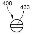
도 11 및 도 12에 도시된 바와 같이, 대안적인 실시예에 따른 앵커링 요소(408)는 뼈 임플란트(100)의 앵커링 요소(108)과 실질적으로 유사하고, 뼈 고정 요소(402)의 헤드 요소(403)를 수용하기 위한 캐비티(409)를 포함한다. 그러나, 외부 나사산 대신에, 앵커링 요소(408)는 이식되었을 때 대퇴부 헤드 단편과 맞물리게 말단으로 연장하는 블레이드(433)를 포함한다.11 and 12, an
도 13 및 도 14에 도시된 바와 같이, 또 다른 실시예에 따른 앵커링 요소(508)는 앵커링 요소(408)와 실질적으로 유사하다. 그러나, 앵커링 요소(508)는 교차 블레이드(534)를 포함한다. 교차 블레이드(534)는 이식되었을 때, 서로에 대하여 실질적으로 수직하게 배열되는 제1 및 제2 블레이드부(535, 536)를 각각 포함한다.13 and 14, the anchoring
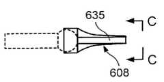
도 15 및 도 16에 도시된 바와 같이, 또 다른 실시예에 따른 앵커링 요소(608)는 앵커링 요소(408)과 실질적으로 유사하다. 그러나, 앵커링 요소(608)는 말단으로 연장하는 나선형 블레이드(635)를 포함하여 이식되었을 때, 대퇴부 헤드 단편과 맞물리게 된다.As shown in FIGS. 15 and 16, an
도 17은 뼈 임플란트(100)의 고정 요소(102)와 실질적으로 유사한 다른 예시적인 실시예에 따른 고정 요소(702)를 보여준다. 그러나, 고정 요소(702)는 앵커링 요소(708)의 근위단(734)으로부터 구형 캐비티(709)까지 연장하는 개구부부(718)를 포함하는 앵커링 요소(708)를 포함한다. 개구부부(718)의 직경은 구형 캐비티(709) 쪽으로 감소하여, 개구부부(718)가 근위단(734)에서 최대가 되어 축(705)과 앵커링 요소(708) 사이에서 가장 넓은 범위의 각형성이 가능하도록 한다. 구형 캐비티(709)는 근위단(734) 쪽으로 점점 가늘어져서, 구형 헤드 요소(703)가 구형 캐비티 내에 물리거나 유지되도록 한다.Figure 17 shows a
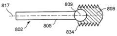
도 18은 고정 요소(102)와 실질적으로 유사한 다른 실시예에 따른 고정 요소(802)를 보여주지만, 뼈 앵커링 요소(808) 내의 구형 캐비티(809)가 오픈되고, 뼈 앵커링 요소(808)의 근위단(834)에 인접하게 배열된다는 점에서만 다르다. 캐비티(809)는 단지 180°조금 넘는 각도 이상으로 연장하여, 구형 헤드 요소(803)가 캐비티 내에 유지되고, 앵커링 요소(808)의 근위단(834)의 축(805)과의 간섭없이, 뼈 앵커링 요소(808)가 중심축(817)에 대하여 적당한 각도 범위 내에서 회전하도록 허용한다.18 shows a securing
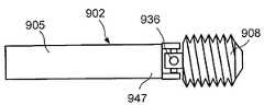
도 19는 상술한 고정 요소(102)에 실질적으로 유사한 다른 실시예에 따른 고정 요소(902)를 보여준다. 그러나, 고정 요소(902)는 구형 헤드 요소 및 상응하는 구형 캐비티를 포함하지 않는다. 오히려, 고정 요소(902)는 카르단 조인트(cardan joint)(936)를 통하여 세로축(905)의 제1단(947)에 결합하는 앵커링 요소(908)를 포함한다.19 shows a
도 20 내지 도 22는 고정 요소(902)와 실질적으로 유사한 다른 실시예에 따른 고정 요소(1002)를 보여준다. 그러나, 카르단 조인트 대신에, 뼈 앵커링 요소(1008)는 유연 부재(1026)를 통하여 축(1005)의 제1단(1047)에 결합한다. 유연 부재(1026)는 도 20에 도시된 바와 같이 탄성중합체를 포함할 수 있거나, 또는 도 21에 도시된 바와 같이 벨로우(bellow)(1027)로서 구성될 수 있거나, 또는 도 22에 도시된 바와 같이 스프링, 바람직하게는 나선형 스프링(1028)으로 구성될 수 있다.Figs. 20-22 show a
도 23 및 도 24에 도시된 바와 같이, 본 발명의 또 다른 실시예에 따른 뼈 임플란트(1100)는 두하 상박 헤드 골절의 치료를 위하여 이용될 수 있다. 뼈 임플란트(1100)는 고정 요소(1102) 및 슬리브(1137)를 포함한다.23 and 24, a
고정 요소(1102)는 축(1105), 구형 헤드 요소(1103) 및 앵커링 요소(1108)를 포함한다. 축(1105)은 제1 원위단(1147)으로부터 제2 근위단(1148)까지 중심축(1117)을 따라 길이방향으로 연장한다. 제1단(1147)은 확대된 직경을 갖는 헤드(1138)를 포함한다. 구형 헤드 요소(1103)는 축(105)이 구형 헤드 요소(1103)의 중심을 통하여 연장하도록, 축(1105)의 원위부(1144) 상에 축(1105)의 원위 헤드(1138)에 인접하게 슬라이딩 가능하게 배열될 수 있다. 축(1105)의 직경은 구형 헤드 요소(1103)의 직경(D)의 대략 50%일 수 있다. 축(1105)의 근위부(1145)는 가로방향으로 연장하는 홀(1146a)을 포함하고, 홀(1146a)은 뼈 나사(1124)의 축부를 수용하도록 구성된다.The
앵커링 요소(1108)는 근위단(1134)으로부터 말단으로 연장하는 캐비티(1139)를 포함한다. 캐비티(1139)는 앵커링 요소(1108)의 원위단 쪽으로 점점 가늘어지는 개구부부(1118)를 포함하고, 다축 회전 방식으로 구형 헤드 요소(1103)를 수용하기 위한 직경(D)을 갖는 부분적 구형 섹션(1140)으로 오픈된다. 개구부부(1118)의 직경은 구형 섹션(1140) 쪽으로 감소하여서, 개구부부가 근위단(1134)에서 최대가 되어 최대 범위의 각도가 고정 요소(1102)의 세로축(1105)과 앵커링 요소(1108) 사이에서 허용되도록 한다. 구형 섹션(1140)은 구형 헤드 요소(1103)가 앵커링 요소(1108)의 구형 섹션(1140) 내에서 유지되도록, 근위단 및 원위단에서 중간 섹션의 직경보다 작은 직경을 갖는 굴곡된 표면을 포함한다. 캐비티(1139)는 세로축(1105)의 헤드(1138)를 수용하기 위하여, 구형 섹션(1140)으로부터 캐비티(1139)의 원위단(1142) 쪽으로 말단으로 연장하는 원통형 섹션(1141)을 더 포함한다. 앵커링 요소(1108)는, 축(1105)의 헤드(1138)가 구형 헤드 요소(1103)에 인접하는 연장된 상태(extended state)와 축(1105)의 헤드(1138)가 캐비티(1139)의 원위단(1142)에 인접하는 단축된 상태(shortened state) 사이에서 슬라이딩 가능하다. 앵커링 요소(1108)는 대퇴부 헤드 단편 내부로 나삽되도록 구성된 외부 나사산(1120)을 가질 수 있다. 더욱이, 고정 요소(1102)는 축(1105)을 통하여 연장하는 케뉼러 배관(1121) 및 중심축(1117)에 실질적으로 동축인 앵커링 요소(1108)를 포함할 수 있다.The
대안적으로, 상술한 실시예에서 설명한 바와 유사하게, 뼈 앵커링 요소(1108)는 카르단 조인트를 통하여 세로축(1105)에 슬라이딩 가능하게 그리고 관절식으로 결합될 수 있거나, 또는 뼈 앵커링 요소(1108)는, 예를 들어 금속성 또는 플라스틱 벨로우, 금속성 또는 플라스틱 스프링 또는 탄성중합체 요소와 같은 유연 부재를 통하여 세로축(1105)에 슬라이딩 가능하게 그리고 유연하게 결합될 수 있다.Alternatively, the
슬리브(1137)는 근위단(1149)으로부터 원위단(1150)까지 중심축(1117)을 따라 세로방향으로 연장하고, 축(1105)의 근위부(1145)를 수용하는 크기 및 형상을 갖는 중심 보어(1143)를 포함한다. 슬리브(1137)는 그 일부를 통하여 가로방향으로 연장하는 홀(1146b)을 포함하고, 슬리브(1137)가 축(1105)의 근위부(1145) 상으로 슬라이딩할 때, 홀(1146b)이 축(1105) 내의 홀(1146a)과 정렬하여 나사(1124)가 양 홀(1146a, 1146b)을 통하여 삽입되고 뼈 내에 뼈 임플란트(1100)를 고정시키도록 한다.The
보어 홀(1110)은 상박골(humerus)의 세로축에 대하여 사선으로 연장하는 상박골의 외측면으로부터 근위 상박골 내부로 뚫린다. 뼈 앵커링 요소(1108)가 뼈 내부로 완전히 진행하면, 상박 헤드 단편이 앵커링 요소(1108)에 고정되도록 앵커링 요소(1108)가 구동함에 따라, 외부 나사산(1120)이 상박 헤드 단편의 뼈 조직으로 끼어들 수 있도록, 보어 홀(1110)은 앵커링 요소(1108)의 외부 나사산(1120)의 코어 직경에 실질적으로 해당하는 직경을 갖는다.The
앵커링 요소(1108)가 보어 홀(1110)의 원위단에 위치하고, 상박 헤드 단편이 앵커링 요소(1108)를 통하여 구형 헤드 요소(1103) 상에 안착될 때까지, 앵커링 요소(1108)는 근위 상박골 내의 보어 홀(1110)로 진행한다. 근위 상박골 내의 보어(1110)의 직경이 축(1105)의 직경(d)보다 크며, 앵커링 요소(1108) 내의 캐비티(1139)가 앵커링 요소(1108)의 근위단(1134)에서 더 큰 개구부부를 가지기 때문에, 구형 섹션(40)은 상박 헤드 단편이 소정 범위의 각형성 내에서 구형 헤드 단편(1103)의 중심(1115)에 대하여 다축 방향으로 회전하도록 한다.The
고정 요소(1102)가 뼈 내부로 진행하면, 슬리브(1137)는 고정 요소(1102)의 축(1105)의 근위부(1145) 상으로 말단으로 슬라이딩되고, 상박골의 축 단편 내에서 연장하는 보어(1110)의 일부로 삽입된다. 고정 요소(1102)의 축(1105)은 슬리브(1137)의 중심 보어(1143) 내에서 축방향으로 안내된다. 세로축(1105)의 가로방향 홀(1146a)과 슬리브(1137)의 가로방향 홀(1146b)은 뼈 나사(1124)를 수용하도록 정렬되어 뼈 내에 슬리브(1137)와 고정 요소(1102)를 고정한다. 구형 헤드 단편(1103)과 그에 부착된 앵커링 요소(1108)는 고정 요소(1102)의 축(1105) 상에서 슬라이딩 가능하게 배열된다. 고정 요소(1102)의 축(1105)과 앵커링 요소(1108) 사이의 슬라이딩 가능한 배열은, 앵커링 요소(1108)가 축방향으로 이동하게 하고, 따라서 도 24에 도시된 바와 같이, 고정 요소(1102)의 중심축(1117)의 방향으로 골절의 역동화를 가능하게 한다. 고정 요소(1102)의 축(1105)에 대한 앵커링 요소(1108)의 최대 축방향 변이(Z)는, 도 25a에 도시된 바와 같이, 앵커링 요소(1108)가 완전히 진행한 위치에 있을 때, 구형 헤드 요소(1103)에 인접하고, 도 25b에 도시된 바와 같이, 앵커링 요소(1108)가 그들의 수축된 위치에 있을 때, 캐비티(1139)의 원위단(1142)에 인접하는 고정 요소(1102)의 헤드(1138)에 의해 제한된다. 앵커링 요소(1108)와 고정 요소(1102)의 축(1105) 사이의 각형성은, 도 26에 도시된 바와 같이, 앵커링 요소(1108)의 근위단(1134)의 개구부부(1118) 또는 축(1105)의 제1단(1147)에서 헤드(1138)를 수용하는 캐비티(1139)의 원통형 섹션(1141)에 의해서 제한된다. 따라서, 앵커링 요소(1108)와 고정 요소(1102)의 축(1105)은 도 26에 도시된 바와 같이, 앵커링 요소(1108)가 그들의 완전히 연장된 위치에 있을 때, 각형성의 최대각(Ωmax)을 갖는다.The
도 27 내지 도 30은 상술한 바와 같은 뼈 임플란트(1)와 실질적으로 유사한 임플란트(1200)의 다른 예시적인 실시예를 보여주고, 대퇴부 헤드 뼈 단편 내부로 뼈 플레이트(1206)의 개구부부를 통하여 삽입될 수 있는 고정 요소(1202)를 포함한다. 그러나, 뼈 임플란트(1200)는 단지 뼈 플레이트(1206)가 고정된 배럴 대신에 회전 가능한 슬리브(1252)를 포함한다는 점에서 뼈 플레이트(1)와 다르다. 슬리브(1252)는 뼈 플레이트(1206) 내의 보어(1251)를 통하여 연장하고, 슬리브(1252)가 회전 가능하도록 허용하는 두 개의 축방향으로 연장하는 연결 요소(1249)를 통하여 뼈 플레이트(1206)에 고정될 수 있다. 보어(1251)는 슬리브(1252)가 보어(1251) 내에서 회전될 수 있도록 슬리브(1252)의 외경보다 큰 직경을 갖는다. 축(1205)의 중심축(1217)에 직교하는 단면에서, 두 개의 연결 요소(1249)는 슬리브(1252)의 반대의 대향 측면에 위치되고, 보어(1251)의 내벽에 일체로 형성되거나 결합될 수 있다. 슬리브(1252)의 연결 요소(1249)는, 슬리브(1252)가 보어(1251)에 회전 가능하게 결합되도록 보어(1251)의 내벽(1254)의 상응하는 리세스(recesses) 내에 수용될 수 있다. 대안적으로, 연결 요소(1249)가 가소 변형되어 축(1205)의 중심축(1217)에 직교하게 연장하는 회전축(pivot axis)(1253)을 정의하도록, 연결 요소(1249)는 슬리브(1252)에 일체로 형성되거나 고정될 수 있다. 따라서, 연결 요소(1249)는, 슬리브(1252)와 뼈 플레이트(1206)의 보어 홀(1251) 사이에 두 개의 동축으로 배열되고 가소 변형가능한 회전 핀을 포함하는 조인트(1250)를 형성한다. 대안적으로, 조인트(1250)는 서로에 대하여 직교하게 배열되는 두 쌍의 회전 핀을 포함하는 카르단 조인트로서 구성될 수 있다.27-30 illustrate another exemplary embodiment of an
매립된 힌지(embedded hinge) 또는 카르단 조인트를 포함하는 골접합(osteosynthetic) 임플란트의 다양한 실시예가 프리그(FRIGG)에 의한 미국 특허 제6,663,632호에 설명된다. 상기 특허의 전문은 여기에 참조로서 통합된다.Various embodiments of osteosynthetic implants, including embedded hinges or cardan joints, are described in U.S. Patent No. 6,663,632 to Freig (FRIGG). The full text of the patent is hereby incorporated by reference.
도 27에 도시된 바와 같이, 고정 요소(1202)는 구형 헤드 요소(1203)가 대퇴부 헤드 뼈 단편 내에 안착되도록, 뼈 내부로 뚫린 보어 홀(210)을 통하여 삽입된다. 슬리브(1252)는 축(1205)의 근위부 상에 장착되어, 도 29에 도시된 바와 같이, 대퇴부 헤드 단편이 구형 헤드 요소(1203) 둘레를 회전할 수 있다. 그런 다음, 뼈 임플란트(1200)는, 도 30의 화살표 B에 의해 나타난 바와 같이, 연결 요소(1249)에 의해 정의된 회전축(1253) 둘레에 슬리브(1252)를 회전시킴으로써, 도 30에 도시된 바와 같이, 대퇴부 헤드가 A 방향으로 변위될 수 있도록 한다. 슬리브(1252)는 가소성 변형가능한 연결 요소(1249) 상에 큰 힘을 인가하는, 예를 들어 상대적으로 긴 레버 장치(lever instrument)를 통하여 회전축(1253) 둘레를 회전된다. 레버를 통하여 연결 요소(1249)에 인가된 힘은 대퇴두 헤드 상에 해부학적으로 발생할 수 있는 임의의 힘보다 매우 커서, 연결 요소(1249)의 변형이 일어나면, 연결 요소(1249)는 뼈 임플란트(1200)에 안정하고(예를 들어, 변형된) 충분한 안정성 제공을 유지한다. 슬리브(1252)를 통한 고정 요소(1202)의 축(1205)과 뼈 플레이트(1206) 사이의 상술한 관절 연결이, 도 7에 도시된 바와 같이, 뼈 플레이트 대신 골수내 네일을 포함하는 뼈 임플란트에 유사하게 적용될 수 있다는 것은 본 발명이 속한 기술분야의 숙련자에 의해 이해될 수 있을 것이다. 뼈 임플란트(1200)가 골수내 네일을 포함하는 경우, 슬리브(1252)는 관통 보어를 통하여 삽입될 수 있고, 상술한 조인트(1250)와 유사한 연결부를 통하여 결합할 수 있는 부싱(bushing)으로 구성될 수 있다. 유사하게, 상술한 관절 연결은 도 23 및 도 24에 도시된 바와 같이 뼈 임플란트(1100)에 또한 적용될 수 있다.As shown in FIG. 27, the securing
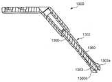
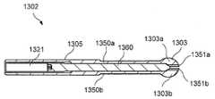
본 발명의 다른 예시적인 실시예가 도 31 내지 도 34에 도시된다. 뼈 임플란트(1300)의 본 실시예는 도 1, 2, 27, 28 및 29에 도시된 실시예와 실질적으로 유사한다. 본 예시적인 실시예에서, 뼈 임플란트(1300)는 뼈 단편 내에 고정 요소를 고정하키기 위하여 제1 반경으로부터 제2 반경까지의 반경을 증가시키도록 확장될 수 있는 구형 헤드 요소(1303)를 포함하는 고정 요소(1302)를 포함한다. 구형 헤드 요소(1303)는 구형 헤드 요소를 확장부(1303a, 1303b)로 분할하도록 배열된 슬릿을 갖는다. 확장부(1303a, 1303b)는 근위단(1350a, 1350b)에서 축(1305)으로 연결된다. 확장부(1303a, 1303b)의 반대측 원위단((1351a, 1351b)은 근위단(1350a, 1350b)에서 연결점에 대하여 연결되지 않으면서 확장될 수 있다. 본 발명이 속한 기술분야의 숙련자에 의해 이해될 수 있는 바와 같이, 확장부(1303a, 1303b)는 슬릿을 가로지르는 균일한 분리부를 가질 수 있고, 확장부는 근위단으로부터 원위단까지 점점 가늘어지거나, 또는 임의의 다른 적당한 개시점, 감소된 직경 및 구성을 가질 수 있다. 예를 들어, K-와이어가 안내 목적을 위하여 고정 요소(1302)에 의해 수용되도록 하는 축(1305) 내의 케뉼러 배관(1321)은 구형 헤드 요소(1303) 내부로 연장될 수 있다. 확장부(1303a, 1303b)를 연장시키기 위하여, 테이퍼 맞물림 단부(tapered engagement end)(미 도시)를 갖는 툴(1360)이 케뉼러 배관 하방으로 눌려지고 확장부(1303a, 1303b)와 맞물릴 수 있다. 구형 헤드 요소(1303)는 두 개의 확장부(1303a, 1303b)를 보여준다. 그러나, 본 발명이 속한 기술분야의 숙련자에 의해 이해될 수 있는 바와 같이, 구형 헤드 요소는 임의의 수의 확장부로 분할되어 헤드 요소(1303)가 확장되도록 할 수 있다.Another exemplary embodiment of the present invention is shown in Figs. 31 to 34. Fig. This embodiment of the
확장부가 슬릿을 가로지르는 균일한 분리부를 가지는 실시예에서, 케뉼러 배관(1321)의 직경은 분리부의 직경보다 크다. 분리부보다 큰 직경을 갖는 툴(1360)은 구형 헤드 요소(1303)에 삽입되어 헤드 요소(1303)를 확장시킨다. 감소된 직경 형상으로부터 증가된 직경 형상으로의 확장은 확장부(1303a, 1303b) 사이에 툴(1360)을 밀어 넣어 툴(1360)의 큰 직경으로 인하여 힘을 가하여 그들을 서로 이격시킴으로써 얻어질 수 있다.In an embodiment in which the extension has a uniform separating portion across the slit, the diameter of the
확장부(1303a, 1303b)가 서로의 방향으로 점점 가늘어지는 실시예에서, 케뉼러 배관(1321)은 요구된 확장량에 따라 동일한 직경 또는 증가된 직경을 가질 수 있다. 본 발명이 속한 기술분야의 숙련자에 의해 이해될 수 있는 바와 같이, 확장은 테이퍼를 펴거나 확장하도록 벽에 작용하는 툴로 인하여 얻어질 수 있다.In embodiments where the
이상 본 발명 및 그 이점이 상세하게 설명되어 있지만, 첨부된 특허청구범위에 의해 정의된 바와 같이 본 발명의 사상 및 범주에 벗어남이 없이 여기에서 다양한 변형, 대체 및 변경이 가능하다는 것을 이해해야 한다. 더욱이, 본 발명의 범위는 본 명세서에서 설명된 공정, 기계, 제조, 물질의 조성, 수단, 방법 및 단계의 특정 실시예에 제한되는 것으로 의도되지 않는다. 본 발명이 속한 기술분야의 숙련자가 본 발명의 개시로부터 쉽게 이해할 수 있는 바와 같이, 여기에서 설명된 해당 실시예와 실질적으로 동일한 기능을 수행하거나 또는 실질적으로 동일한 결과를 얻는 현재에 존재하거나 또는 이후에 개발될 공정, 기계, 제조, 물질의 조성, 수단, 방법 또는 단계가 본 발명에 따라 활용될 수 있을 것이다. 본 발명의 다양한 수정 및 변경이 첨부된 청구범위의 광범위한 범위를 벗어나지 않고 만들어질 수 있다는 것이 본 발명이 속한 기술분야에서 통상의 지식을 가진 자에 의해 이해될 것이다. 이들 중 일부는 위에서 설명되었으며 다른 것 역시 통상의 지식을 자에게 명백할 것이다.
Although the present invention and its advantages have been described in detail, it should be understood that various changes, substitutions and alterations can be made therein without departing from the spirit and scope of the invention as defined by the appended claims. Moreover, the scope of the present invention is not intended to be limited to the specific embodiments of the process, machine, manufacture, composition of matter, means, methods and steps described herein. As one of ordinary skill in the art will readily appreciate from the disclosure of the present invention, it is to be understood that the present invention may be practiced otherwise than as described herein, The process, machine, manufacture, composition of matter, means, method or step to be developed may be utilized in accordance with the present invention. It will be understood by those skilled in the art that various modifications and variations of the present invention can be made without departing from the broad scope of the appended claims. Some of these have been described above and others will also be apparent to those of ordinary skill in the art.
Claims (32)
Translated fromKorean상기 축의 제1단에 부착되고, 반경(R>r)을 갖고, 골절 부분이 축의 중심축에 대하여 구형 헤드 요소 둘레를 회전하도록 뼈의 골절 부분 내부로 삽입되도록 구성된 구형 헤드 요소를 포함하는, 골단 골절을 치료하는 고정 장치.An axis configured to slidably engage a bone implant opening and having a maximum radius r and extending longitudinally along a central axis from a first end to a second end; And
And a spherical head element attached to the first end of the shaft and configured to have a radius (R > r) and to be inserted into the fracture portion of the bone such that the fracture portion rotates about the spherical head element with respect to the central axis of the shaft. Fixation device to treat fractures.
상기 축의 제1단에 이동 가능하게 결합되고, 축의 직경보다 큰 직경을 갖고, 축의 중심축에 대하여 회전가능하고, 뼈 내에 삽입 시 뼈의 골절 부분과 맞물리는 구조를 갖는 뼈 앵커링 요소를 포함하는, 골단 골절을 치료하는 고정 장치.An axis extending longitudinally along the central axis from the first end to the second end; And
A bone anchoring element movably coupled to the first end of the shaft and having a diameter greater than the diameter of the shaft and rotatable about a central axis of the shaft and configured to engage a fractured portion of the bone upon insertion into the bone, Fixation device to treat golinal fractures.
뼈 임플란트의 개구부부와 슬라이딩 가능하게 맞물리게 구성되고, 원위단으로부터 근위단까지 중심축을 따라 연장하는 축; 및 상기 축의 원위단에 이동 가능하게 결합되고, 축의 직경보다 큰 직경을 갖는 뼈 앵커링 요소를 포함하는 골 고정 장치를 포함하는, 골단 뼈 골절을 치료하는 시스템.An elongated bone implant comprising an opening extending along a longitudinal axis and extending through an axis; And
An axis configured to slidably engage an opening of the bone implant and extending along a central axis from the distal end to the proximal end; And a bone anchoring element movably coupled to the distal end of the shaft and having a diameter greater than the diameter of the shaft.
뼈 임플란트의 개구부부와 슬라이딩 가능하게 맞물리도록 구성되고, 원위단으로부터 근위단까지 중심축을 따라 연장하는 축; 및 상기 축의 제1단에 부착되고 반경(R>r)을 갖고, 골절 부분이 축의 중심축에 대하여 구형 헤드 요소 둘레를 회전하도록 뼈의 골절 부분 내부로 삽입되도록 구성된 구형 헤드 요소를 포함하는 골 고정 장치를 포함하는, 골단 뼈 골절을 치료하기 위한 시스템.An elongated bone implant comprising an opening extending along a longitudinal axis and extending through an axis; And
An axis configured to slidably engage an opening portion of a bone implant and extending along a central axis from a distal end to a proximal end; And a spherical head element affixed to the first end of the shaft and having a radius (R > r) and adapted to be inserted into a fractured portion of the bone such that the fracture portion rotates about the spherical head element with respect to the central axis of the shaft ≪ / RTI > The system of claim 1,
긴 뼈 외측면으로부터 긴뼈 내부로 보어 홀을 뚫는 단계; 및
축의 원위단에 이동 가능하게 결합된 뼈 앵커링 요소를 골절된 뼈의 원하는 부분 내에 위치시켜 뼈 단편이 축의 중심축에 대하여 회전 가능하도록, 보어 홀 내부로 고정 장치를 삽입하는 단계를 포함하는, 골단 뼈 골절을 치료하는 방법.A guide wire disposed in a long bone in a direction transverse to the longitudinal axis of the long bone; Penetrating into a bone fragment through an axial fragment of a long bone;
Drilling a bore hole from the long bone outer side into the long bone; And
Placing a bone anchoring element movably coupled to a distal end of the shaft within a desired portion of the fractured bone and inserting a locking device into the bore hole such that the bone fragment is rotatable about a central axis of the shaft, How to Treat Fractures.
Applications Claiming Priority (3)
| Application Number | Priority Date | Filing Date | Title |
|---|---|---|---|
| US40723110P | 2010-10-27 | 2010-10-27 | |
| US61/407,231 | 2010-10-27 | ||
| PCT/US2011/057295WO2012058113A1 (en) | 2010-10-27 | 2011-10-21 | Bone implant |
Publications (2)
| Publication Number | Publication Date |
|---|---|
| KR20130127442Atrue KR20130127442A (en) | 2013-11-22 |
| KR101964030B1 KR101964030B1 (en) | 2019-04-02 |
Family
ID=44908122
Family Applications (1)
| Application Number | Title | Priority Date | Filing Date |
|---|---|---|---|
| KR1020137009966AExpired - Fee RelatedKR101964030B1 (en) | 2010-10-27 | 2011-10-21 | Bone implant |
Country Status (9)
| Country | Link |
|---|---|
| US (1) | US10675068B2 (en) |
| EP (1) | EP2632356B1 (en) |
| JP (1) | JP6022465B2 (en) |
| KR (1) | KR101964030B1 (en) |
| CN (1) | CN103189006B (en) |
| BR (1) | BR112013007017A2 (en) |
| CA (1) | CA2812317C (en) |
| TW (1) | TWI471114B (en) |
| WO (1) | WO2012058113A1 (en) |
Cited By (2)
| Publication number | Priority date | Publication date | Assignee | Title |
|---|---|---|---|---|
| KR20240009103A (en) | 2022-07-13 | 2024-01-22 | 주식회사 이엔에스 | Self-expandable implant device for bone fracture surgery |
| KR20250016788A (en) | 2023-07-26 | 2025-02-04 | 주식회사 이엔에스 | Intramedullary fixation implants manufactured by 3d printing |
Families Citing this family (28)
| Publication number | Priority date | Publication date | Assignee | Title |
|---|---|---|---|---|
| US7951198B2 (en)* | 2005-05-10 | 2011-05-31 | Acumed Llc | Bone connector with pivotable joint |
| KR101503665B1 (en)* | 2007-06-22 | 2015-03-18 | 이픽스 오소페딕스, 인코포레이티드 | Intramedullary rod for pivoting a fastener |
| US20110046625A1 (en)* | 2008-05-07 | 2011-02-24 | Tornier | Surgical technique and apparatus for proximal humeral fracture repair |
| US8926611B2 (en)* | 2009-09-14 | 2015-01-06 | Zimmer Gmbh | Angular lag implant for intramedullary nails |
| US20120226278A1 (en)* | 2010-09-20 | 2012-09-06 | Nardini Reto | Intramedullary Nail |
| GB201105243D0 (en) | 2011-03-29 | 2011-05-11 | Depuy Ireland | An implant |
| JP6247644B2 (en) | 2012-02-08 | 2017-12-13 | エピックス オーソペディックス インコーポレイテッド | Implant insertion device having a continuously adjustable targeting assembly |
| EP2887896B1 (en)* | 2012-08-23 | 2017-04-19 | Synthes GmbH | Bone implant |
| US9452005B2 (en) | 2012-08-23 | 2016-09-27 | DePuy Synthes Products, Inc. | Bone fixation system |
| US10004603B2 (en) | 2012-08-23 | 2018-06-26 | DePuy Synthes Products, Inc. | Bone implant |
| US9398928B2 (en)* | 2012-09-28 | 2016-07-26 | DePuy Synthes Products, Inc. | Adjustable height arthroplasty plate |
| US9463055B2 (en) | 2013-12-09 | 2016-10-11 | Acumed Llc | Plate-based compliant hip fixation system |
| US9526542B2 (en) | 2014-05-07 | 2016-12-27 | Acumed Llc | Hip fixation with load-controlled dynamization |
| US9433451B2 (en) | 2013-12-09 | 2016-09-06 | Acumed Llc | Hip fixation system with a compliant fixation element |
| US10080596B2 (en) | 2013-12-09 | 2018-09-25 | Acumed Llc | Hip fixation with load-controlled dynamization |
| ES2805053T3 (en) | 2013-12-09 | 2021-02-10 | Acumed Llc | Nail-based elastic hip fixation system |
| WO2015089199A1 (en)* | 2013-12-10 | 2015-06-18 | Acumed Llc | Hip fixation system with a compliant fixation element |
| ES2988981T3 (en)* | 2014-05-07 | 2024-11-22 | Acumed Llc | Hip fixation with load-controlled dynamization |
| CN107252364B (en)* | 2017-07-06 | 2023-09-12 | 武汉市黄陂区人民医院 | A 3D printed humerus model and its preparation method |
| MX2020003481A (en) | 2017-10-11 | 2020-12-07 | Howmedica Osteonics Corp | Humeral fixation plate guides. |
| US10512495B2 (en) | 2017-12-28 | 2019-12-24 | Industrial Technology Research Institute | Method for fabricating medical device and applications thereof |
| CN108992156B (en)* | 2018-09-07 | 2024-03-15 | 北京爱康宜诚医疗器材有限公司 | Bone connector |
| RU197121U1 (en)* | 2019-06-24 | 2020-04-02 | Анатолий Львович Матвеев | DEVICE FOR HIP JOINT AND HIP JOINT AND PREVENTION OF PROXIMAL FEMOR FRACTURES |
| CN110368141B (en)* | 2019-08-05 | 2024-10-22 | 北京爱康宜诚医疗器材有限公司 | Femoral Implants |
| CN112244978B (en)* | 2020-10-20 | 2025-02-18 | 重庆大清生物有限公司 | A support rod for femoral head necrosis and use method thereof |
| US11583411B2 (en)* | 2020-10-27 | 2023-02-21 | Loubert S. Suddaby | Expandable intervertebral fusion implant |
| KR102559610B1 (en) | 2021-01-22 | 2023-07-24 | 임진용 | Femur fracture fixation apparatus |
| DE102021202281A1 (en) | 2021-03-09 | 2022-09-15 | Karl Leibinger Medizintechnik Gmbh & Co. Kg | Anchorable Implant Assembly |
Citations (3)
| Publication number | Priority date | Publication date | Assignee | Title |
|---|---|---|---|---|
| US2381050A (en)* | 1943-12-04 | 1945-08-07 | Mervyn G Hardinge | Fracture reducing device |
| JPH0898846A (en)* | 1994-09-30 | 1996-04-16 | Homuzu Giken:Kk | Connector for femur |
| WO1998001078A1 (en)* | 1996-07-04 | 1998-01-15 | Vagn Erik Dall | Hip compression screw assemblies and joints therefor |
Family Cites Families (34)
| Publication number | Priority date | Publication date | Assignee | Title |
|---|---|---|---|---|
| US3554193A (en)* | 1968-07-05 | 1971-01-12 | Ilias Konstantinou | Femur-setting surgical device |
| USRE32488E (en)* | 1982-09-28 | 1987-09-01 | Hip prosthesis | |
| DE3445738A1 (en)* | 1984-12-14 | 1986-06-19 | Draenert Klaus | IMPLANT FOR BONE REINFORCEMENT AND ANCHORING OF BONE SCREWS, IMPLANTS OR IMPLANT PARTS |
| DE3534747A1 (en)* | 1985-09-28 | 1987-04-09 | Hasselbach Christoph Von | THIGH NECK IMPLANT |
| US4776330A (en) | 1986-06-23 | 1988-10-11 | Pfizer Hospital Products Group, Inc. | Modular femoral fixation system |
| AT398529B (en) | 1991-01-25 | 1994-12-27 | Winkler Heinz Dr | ENDOPROTHESIS, ESPECIALLY THE HIP JOINT |
| US5658339A (en)* | 1996-01-05 | 1997-08-19 | Wright Medical Technology, Inc. | Compression hip screw plate |
| NL1005234C2 (en)* | 1997-02-10 | 1998-08-11 | Novarticulate Bv | Hip replacement and a method of placing such a hip replacement. |
| JPH1189860A (en)* | 1997-09-18 | 1999-04-06 | Senko Medical Instr Mfg Co Ltd | Artificial ligament |
| US5984926A (en)* | 1998-02-24 | 1999-11-16 | Jones; A. Alexander M. | Bone screw shimming and bone graft containment system and method |
| US6139552A (en)* | 1998-05-13 | 2000-10-31 | K. K. Hollyx | Bone jointer and a bone jointer fixing tool |
| ATE256432T1 (en) | 1998-05-19 | 2004-01-15 | Synthes Ag | OSTEOSYNTHETIC IMPLANT WITH EMBEDDED JOINT CONNECTION |
| US6296644B1 (en)* | 1998-08-26 | 2001-10-02 | Jean Saurat | Spinal instrumentation system with articulated modules |
| NL1016551C2 (en)* | 2000-11-07 | 2002-05-14 | Erik Leonard Hoffman | Fastening element, for hip prosthesis, has plate-shaped supporting element, and hollow pin driven into spongy bone, and secured by fixing plate and openings through which bone can grow |
| US6887243B2 (en)* | 2001-03-30 | 2005-05-03 | Triage Medical, Inc. | Method and apparatus for bone fixation with secondary compression |
| WO2004100809A1 (en)* | 2003-05-08 | 2004-11-25 | Bickley Barry T | Fixation augmentation device and related techniques |
| CN100374093C (en)* | 2003-03-13 | 2008-03-12 | 钱本文 | Artificial hip joint device without handle |
| US7862586B2 (en)* | 2003-11-25 | 2011-01-04 | Life Spine, Inc. | Spinal stabilization systems |
| WO2005094707A2 (en)* | 2004-03-26 | 2005-10-13 | Smith & Nephew, Inc. | Methods for treating fractures of the femur and femoral fracture devices |
| US7136309B2 (en)* | 2004-08-02 | 2006-11-14 | Texas Instruments Incorporated | FIFO with multiple data inputs and method thereof |
| US20060229609A1 (en)* | 2005-03-18 | 2006-10-12 | Chao-Jan Wang | Microadjustment spinal joint fixture |
| US7828828B2 (en)* | 2005-04-14 | 2010-11-09 | Warsaw Orthopedic, Inc | Intervertebral joint |
| US7951198B2 (en)* | 2005-05-10 | 2011-05-31 | Acumed Llc | Bone connector with pivotable joint |
| CN2852972Y (en) | 2005-11-18 | 2007-01-03 | 财团法人长庚纪念医院 | Variable Angle DHS Femoral Fixator |
| JP4978906B2 (en)* | 2006-10-17 | 2012-07-18 | 周 中村 | Fracture fixation device for femoral trochanteric fracture |
| US8221479B2 (en)* | 2007-01-19 | 2012-07-17 | Pbj, Llc | Orthopedic screw insert |
| US8317845B2 (en)* | 2007-01-19 | 2012-11-27 | Alexa Medical, Llc | Screw and method of use |
| AU2008306998B2 (en)* | 2007-09-26 | 2014-04-10 | Markus Kuster | Bone anchoring device for the operative repair of fractures |
| KR100992294B1 (en)* | 2008-02-29 | 2010-11-05 | 김선영 | consent |
| CA2722607A1 (en)* | 2008-04-28 | 2009-11-05 | Stephen J. Lewis | Anchor for use with orthopedic screw |
| TW201031381A (en) | 2009-02-24 | 2010-09-01 | Univ Nat Yang Ming | The anti-subsidence dynamic coupling fixation plate for proximal femoral fracture |
| US8926611B2 (en)* | 2009-09-14 | 2015-01-06 | Zimmer Gmbh | Angular lag implant for intramedullary nails |
| BR112014011984B1 (en)* | 2011-11-18 | 2021-02-09 | Synthes Gmbh | bone fixation system |
| US8956394B1 (en)* | 2014-08-05 | 2015-02-17 | Woven Orthopedic Technologies, Llc | Woven retention devices, systems and methods |
- 2011
- 2011-10-21JPJP2013536685Apatent/JP6022465B2/ennot_activeExpired - Fee Related
- 2011-10-21BRBR112013007017Apatent/BR112013007017A2/enactiveSearch and Examination
- 2011-10-21WOPCT/US2011/057295patent/WO2012058113A1/enactiveApplication Filing
- 2011-10-21USUS13/278,805patent/US10675068B2/enactiveActive
- 2011-10-21CNCN201180052427.0Apatent/CN103189006B/ennot_activeExpired - Fee Related
- 2011-10-21CACA2812317Apatent/CA2812317C/ennot_activeExpired - Fee Related
- 2011-10-21EPEP11779295.2Apatent/EP2632356B1/ennot_activeNot-in-force
- 2011-10-21KRKR1020137009966Apatent/KR101964030B1/ennot_activeExpired - Fee Related
- 2011-10-27TWTW100139027Apatent/TWI471114B/ennot_activeIP Right Cessation
Patent Citations (3)
| Publication number | Priority date | Publication date | Assignee | Title |
|---|---|---|---|---|
| US2381050A (en)* | 1943-12-04 | 1945-08-07 | Mervyn G Hardinge | Fracture reducing device |
| JPH0898846A (en)* | 1994-09-30 | 1996-04-16 | Homuzu Giken:Kk | Connector for femur |
| WO1998001078A1 (en)* | 1996-07-04 | 1998-01-15 | Vagn Erik Dall | Hip compression screw assemblies and joints therefor |
Cited By (2)
| Publication number | Priority date | Publication date | Assignee | Title |
|---|---|---|---|---|
| KR20240009103A (en) | 2022-07-13 | 2024-01-22 | 주식회사 이엔에스 | Self-expandable implant device for bone fracture surgery |
| KR20250016788A (en) | 2023-07-26 | 2025-02-04 | 주식회사 이엔에스 | Intramedullary fixation implants manufactured by 3d printing |
Also Published As
| Publication number | Publication date |
|---|---|
| EP2632356A1 (en) | 2013-09-04 |
| KR101964030B1 (en) | 2019-04-02 |
| TWI471114B (en) | 2015-02-01 |
| BR112013007017A2 (en) | 2017-07-25 |
| JP6022465B2 (en) | 2016-11-09 |
| CA2812317A1 (en) | 2012-05-03 |
| US20120109128A1 (en) | 2012-05-03 |
| WO2012058113A1 (en) | 2012-05-03 |
| CN103189006A (en) | 2013-07-03 |
| CN103189006B (en) | 2016-09-21 |
| TW201219004A (en) | 2012-05-16 |
| US10675068B2 (en) | 2020-06-09 |
| JP2013544129A (en) | 2013-12-12 |
| EP2632356B1 (en) | 2017-05-24 |
| CA2812317C (en) | 2020-05-05 |
Similar Documents
| Publication | Publication Date | Title |
|---|---|---|
| KR101964030B1 (en) | Bone implant | |
| US20210161575A1 (en) | Bone fixation system, assembly, implants, devices, alignment guides, and methods of use | |
| US10751097B2 (en) | Intraosseous intramedullary fixation assembly and method of use | |
| US20190192189A1 (en) | Bone Compression and Fixation Devices | |
| US9289220B2 (en) | Intramedullary fixation assembly and method of use | |
| US20170079703A1 (en) | Humeral Head Fixation Device for Osteoporotic Bone | |
| US8876822B2 (en) | Intramedullary nail system with tang fixation after lock screw placement | |
| US20110230884A1 (en) | Hybrid intramedullary fixation assembly and method of use | |
| US11918261B2 (en) | Locking system for femoral neck fracture fixation | |
| EP1887952B1 (en) | Device for covered screwing of broken and shortened bones | |
| US9622798B2 (en) | Intramedullary compression rod | |
| US20150374420A1 (en) | Phalangeal head plate | |
| WO2008097795A1 (en) | Sliding hip helical implant |
Legal Events
| Date | Code | Title | Description |
|---|---|---|---|
| PA0105 | International application | St.27 status event code:A-0-1-A10-A15-nap-PA0105 | |
| PG1501 | Laying open of application | St.27 status event code:A-1-1-Q10-Q12-nap-PG1501 | |
| PN2301 | Change of applicant | St.27 status event code:A-3-3-R10-R13-asn-PN2301 St.27 status event code:A-3-3-R10-R11-asn-PN2301 | |
| R17-X000 | Change to representative recorded | St.27 status event code:A-3-3-R10-R17-oth-X000 | |
| A201 | Request for examination | ||
| P11-X000 | Amendment of application requested | St.27 status event code:A-2-2-P10-P11-nap-X000 | |
| P13-X000 | Application amended | St.27 status event code:A-2-2-P10-P13-nap-X000 | |
| PA0201 | Request for examination | St.27 status event code:A-1-2-D10-D11-exm-PA0201 | |
| D13-X000 | Search requested | St.27 status event code:A-1-2-D10-D13-srh-X000 | |
| D14-X000 | Search report completed | St.27 status event code:A-1-2-D10-D14-srh-X000 | |
| E902 | Notification of reason for refusal | ||
| PE0902 | Notice of grounds for rejection | St.27 status event code:A-1-2-D10-D21-exm-PE0902 | |
| T11-X000 | Administrative time limit extension requested | St.27 status event code:U-3-3-T10-T11-oth-X000 | |
| T11-X000 | Administrative time limit extension requested | St.27 status event code:U-3-3-T10-T11-oth-X000 | |
| T11-X000 | Administrative time limit extension requested | St.27 status event code:U-3-3-T10-T11-oth-X000 | |
| T11-X000 | Administrative time limit extension requested | St.27 status event code:U-3-3-T10-T11-oth-X000 | |
| T11-X000 | Administrative time limit extension requested | St.27 status event code:U-3-3-T10-T11-oth-X000 | |
| T13-X000 | Administrative time limit extension granted | St.27 status event code:U-3-3-T10-T13-oth-X000 | |
| E13-X000 | Pre-grant limitation requested | St.27 status event code:A-2-3-E10-E13-lim-X000 | |
| P11-X000 | Amendment of application requested | St.27 status event code:A-2-2-P10-P11-nap-X000 | |
| P13-X000 | Application amended | St.27 status event code:A-2-2-P10-P13-nap-X000 | |
| E701 | Decision to grant or registration of patent right | ||
| PE0701 | Decision of registration | St.27 status event code:A-1-2-D10-D22-exm-PE0701 | |
| GRNT | Written decision to grant | ||
| PR0701 | Registration of establishment | St.27 status event code:A-2-4-F10-F11-exm-PR0701 | |
| PR1002 | Payment of registration fee | St.27 status event code:A-2-2-U10-U12-oth-PR1002 Fee payment year number:1 | |
| PG1601 | Publication of registration | St.27 status event code:A-4-4-Q10-Q13-nap-PG1601 | |
| PC1903 | Unpaid annual fee | St.27 status event code:A-4-4-U10-U13-oth-PC1903 Not in force date:20220327 Payment event data comment text:Termination Category : DEFAULT_OF_REGISTRATION_FEE | |
| PC1903 | Unpaid annual fee | St.27 status event code:N-4-6-H10-H13-oth-PC1903 Ip right cessation event data comment text:Termination Category : DEFAULT_OF_REGISTRATION_FEE Not in force date:20220327 |