KR20130127435A - Bone plate assembly with guide member - Google Patents
Bone plate assembly with guide memberDownload PDFInfo
- Publication number
- KR20130127435A KR20130127435AKR1020137008758AKR20137008758AKR20130127435AKR 20130127435 AKR20130127435 AKR 20130127435AKR 1020137008758 AKR1020137008758 AKR 1020137008758AKR 20137008758 AKR20137008758 AKR 20137008758AKR 20130127435 AKR20130127435 AKR 20130127435A
- Authority
- KR
- South Korea
- Prior art keywords
- guide member
- hole
- spherical
- segment
- plate assembly
- Prior art date
- Legal status (The legal status is an assumption and is not a legal conclusion. Google has not performed a legal analysis and makes no representation as to the accuracy of the status listed.)
- Withdrawn
Links
Images


Classifications
- A—HUMAN NECESSITIES
- A61—MEDICAL OR VETERINARY SCIENCE; HYGIENE
- A61B—DIAGNOSIS; SURGERY; IDENTIFICATION
- A61B17/00—Surgical instruments, devices or methods
- A61B17/56—Surgical instruments or methods for treatment of bones or joints; Devices specially adapted therefor
- A61B17/58—Surgical instruments or methods for treatment of bones or joints; Devices specially adapted therefor for osteosynthesis, e.g. bone plates, screws or setting implements
- A61B17/68—Internal fixation devices, including fasteners and spinal fixators, even if a part thereof projects from the skin
- A61B17/80—Cortical plates, i.e. bone plates; Instruments for holding or positioning cortical plates, or for compressing bones attached to cortical plates
- A—HUMAN NECESSITIES
- A61—MEDICAL OR VETERINARY SCIENCE; HYGIENE
- A61B—DIAGNOSIS; SURGERY; IDENTIFICATION
- A61B17/00—Surgical instruments, devices or methods
- A61B17/16—Instruments for performing osteoclasis; Drills or chisels for bones; Trepans
- A61B17/17—Guides or aligning means for drills, mills, pins or wires
- A61B17/1728—Guides or aligning means for drills, mills, pins or wires for holes for bone plates or plate screws
- A—HUMAN NECESSITIES
- A61—MEDICAL OR VETERINARY SCIENCE; HYGIENE
- A61B—DIAGNOSIS; SURGERY; IDENTIFICATION
- A61B17/00—Surgical instruments, devices or methods
- A61B17/56—Surgical instruments or methods for treatment of bones or joints; Devices specially adapted therefor
- A61B17/58—Surgical instruments or methods for treatment of bones or joints; Devices specially adapted therefor for osteosynthesis, e.g. bone plates, screws or setting implements
- A61B17/68—Internal fixation devices, including fasteners and spinal fixators, even if a part thereof projects from the skin
- A61B17/70—Spinal positioners or stabilisers, e.g. stabilisers comprising fluid filler in an implant
- A—HUMAN NECESSITIES
- A61—MEDICAL OR VETERINARY SCIENCE; HYGIENE
- A61B—DIAGNOSIS; SURGERY; IDENTIFICATION
- A61B17/00—Surgical instruments, devices or methods
- A61B17/56—Surgical instruments or methods for treatment of bones or joints; Devices specially adapted therefor
- A61B17/58—Surgical instruments or methods for treatment of bones or joints; Devices specially adapted therefor for osteosynthesis, e.g. bone plates, screws or setting implements
- A61B17/68—Internal fixation devices, including fasteners and spinal fixators, even if a part thereof projects from the skin
- A61B17/84—Fasteners therefor or fasteners being internal fixation devices
- A61B17/86—Pins or screws or threaded wires; nuts therefor
- A—HUMAN NECESSITIES
- A61—MEDICAL OR VETERINARY SCIENCE; HYGIENE
- A61B—DIAGNOSIS; SURGERY; IDENTIFICATION
- A61B17/00—Surgical instruments, devices or methods
- A61B17/16—Instruments for performing osteoclasis; Drills or chisels for bones; Trepans
- A61B17/17—Guides or aligning means for drills, mills, pins or wires
- A61B17/1739—Guides or aligning means for drills, mills, pins or wires specially adapted for particular parts of the body
- A61B17/1757—Guides or aligning means for drills, mills, pins or wires specially adapted for particular parts of the body for the spine
- A—HUMAN NECESSITIES
- A61—MEDICAL OR VETERINARY SCIENCE; HYGIENE
- A61B—DIAGNOSIS; SURGERY; IDENTIFICATION
- A61B17/00—Surgical instruments, devices or methods
- A61B17/56—Surgical instruments or methods for treatment of bones or joints; Devices specially adapted therefor
- A61B17/58—Surgical instruments or methods for treatment of bones or joints; Devices specially adapted therefor for osteosynthesis, e.g. bone plates, screws or setting implements
- A61B17/68—Internal fixation devices, including fasteners and spinal fixators, even if a part thereof projects from the skin
- A61B17/80—Cortical plates, i.e. bone plates; Instruments for holding or positioning cortical plates, or for compressing bones attached to cortical plates
- A61B17/8052—Cortical plates, i.e. bone plates; Instruments for holding or positioning cortical plates, or for compressing bones attached to cortical plates immobilised relative to screws by interlocking form of the heads and plate holes, e.g. conical or threaded
- A61B17/8057—Cortical plates, i.e. bone plates; Instruments for holding or positioning cortical plates, or for compressing bones attached to cortical plates immobilised relative to screws by interlocking form of the heads and plate holes, e.g. conical or threaded the interlocking form comprising a thread
Landscapes
- Health & Medical Sciences (AREA)
- Orthopedic Medicine & Surgery (AREA)
- Surgery (AREA)
- Life Sciences & Earth Sciences (AREA)
- Heart & Thoracic Surgery (AREA)
- Veterinary Medicine (AREA)
- Engineering & Computer Science (AREA)
- Biomedical Technology (AREA)
- Nuclear Medicine, Radiotherapy & Molecular Imaging (AREA)
- Medical Informatics (AREA)
- Molecular Biology (AREA)
- Animal Behavior & Ethology (AREA)
- General Health & Medical Sciences (AREA)
- Public Health (AREA)
- Neurology (AREA)
- Dentistry (AREA)
- Oral & Maxillofacial Surgery (AREA)
- Surgical Instruments (AREA)
Abstract
Translated fromKoreanDescription
Translated fromKorean본 출원서는 2010년 10월 7일에 출원된 미국 가출원 제 61/390869호 및 2011년 3월 24일에 출원된 유럽 특허 출원 제 11 159 670.6호에 대해 우선권의 이익을 주장하고 또한 참조에 의해 전부 반영한다.This application claims the benefit of priority over US Provisional Application No. 61/390869, filed October 7, 2010 and European Patent Application No. 11 159 670.6, filed March 24, 2011, and is also incorporated by reference in its entirety. Reflect.
본 발명은 뼈들 또는 뼈 조각들 또는 척추뼈의 고정에 사용되는 본 플레이트 조립체에 관한 것이다. 상기 본 플레이트 조립체는 드릴 날(drill bit)을 안내하는 안내 부재, 상기 본 플레이트의 정확한 배치에 사용되는 기구 또는 안내 배선을 포함한다. 특히, 본 발명은 상기 안내 부재와 상기 플레이트 사이에 다축성 커플링(polyaxial coupling)을 가지는 본 플레이트 조립체에 관한 것이다.The present invention relates to a bone plate assembly for use in securing bones or bone fragments or vertebrae. The bone plate assembly includes a guide member for guiding a drill bit, a mechanism or a guide wire used for correct placement of the bone plate. In particular, the present invention relates to a bone plate assembly having a polyaxial coupling between the guide member and the plate.
미국 공개특허 제 2006/0149250호는 접골 나사들(bone screws)을 수령하기 위한 복수의 나사산 있는 홀들을 가지는 본 플레이트를 개시하고, 상기 나사산 있는 홀들은 각각 축들을 가지는데, 이것은 경사가 있을 수 있고, 복수의 제거가능한 드릴 안내 팁들은 상기 축들에 맞춰 정렬되어 상기 나사산 있는 홀들에 조립된다.US 2006/0149250 discloses a bone plate having a plurality of threaded holes for receiving bone screws, the threaded holes each having axes, which may be inclined and A plurality of removable drill guide tips are aligned with the axes and assembled into the threaded holes.
유럽 공개특허 제 1 878 394호는 구형으로 굽은 내부 표면을 가지는 홀 및 상기 홀 안에 제공되는 다축성 부싱(polyaxial bushing)을 포함하는 고정 플레이트를 포함하는 정형외과 고정 플레이트 시스템을 개시한다. 제거가능한 안내부(guide)가 상기 다축성 부싱 안에 제공된다. 상기 다축성 부싱들은 외과의사들이 상기 부싱을 소정의 방향(orientation)으로 잠금(locking)하기 전에 상기 안내부를 상기 부싱 안에 단단히 조이는 것에 의해, 선택된 방향(orientation)으로 각각의 안내부와 부싱의 각도를 변형할 수 있도록 허용한다.
일반적으로 알려진 바와 같이, 이러한 본 플레이트가 뼈 위에 놓이고 하나의 본 앵커(bone anchor)가 삽입된 후, 상기 본 앵커들이 완전히 조여지기만 하면 나머지 본 앵커들을 상기 본 플레이트 볼 안착부(ball seat)에 맞게 정렬하는 것은 어렵다. 하지만, 이러한 본 앵커들은 정확히 그 위치에 배치되어, 이러한 본 앵커들이 조여지기만 하면 상기 본 앵커들의 볼 형상 부분(ball-shaped portion)이 상기 플레이트 내의 볼 형상의 안착부에 정확히 배열될 필요가 있다. 상기 본 앵커들의 상기 볼 형상 부분과 상기 플레이트 내의 상기 볼 형상 안착부의 정렬 불량(misalignment)은 상기 본에 스트레스를 야기시키고 또한 이것은 상기 플레이트의 올바른 기능을 막는다.As is generally known, after this bone plate has been placed on a bone and one bone anchor has been inserted, the other bone anchors are placed on the bone plate ball seat as long as the bone anchors are fully tightened. It is difficult to align it. However, these bone anchors are positioned precisely in such a position that, once the bone anchors are tightened, the ball-shaped portions of the bone anchors need to be exactly arranged in the ball-shaped seating portion in the plate. Misalignment of the ball-shaped portion of the bone anchors and the ball-shaped seating in the plate causes stress on the bone and also prevents the correct functioning of the plate.
그러므로, 본 발명의 목적은 본 플레이트에 다축성으로 결합되고 또한 단순하고 다용도로 사용될 수 있는, 접골나사들과 사용하기에 적합한 안내 부재를 가지는 본 플레이트 조립체를 제공하는 데 있다.It is therefore an object of the present invention to provide a bone plate assembly having a guide member suitable for use with the osteotomy screws, which can be multiaxially coupled to the bone plate and which can be used simply and versatilely.
본 목적 뿐만 아니라 다른 개선사항들은 여기에 설명된 실시예들에 따른 본 플레이트 조립체에 의해 해결될 수 있다.Other improvements as well as this object can be solved by the bone plate assembly according to the embodiments described herein.
상기 안내 부재는 상기 접골나사를 수령하도록 마련된 상기 본 플레이트 내의 상기 홀(hole)에 제거가능하게 삽입될 수 있는 삽입부(insert) 및 상기 홀 내의 상기 접골나사를 잠그기 위한 잠금 부재(locking member)에 의해 고정된다. 상기 삽입부는 상기 접골나사의 상기 잠금 부재와 동일한 방식으로 상기 홀 내에 고정될 수 있다. 이것은 외과의사가 쉽게 상기 삽입부를 상기 홀 안에 배치하고 그후 뼈에 상기 접골나사를 위한 홀을 뚫기 위한 안내 부재를 사용하는 것을 허용한다.The guide member includes an insert that can be removably inserted into the hole in the bone plate provided to receive the bone screw and a locking member for locking the bone screw in the hole. Is fixed by. The insertion portion may be fixed in the hole in the same manner as the locking member of the folding screw. This allows the surgeon to easily place the insert into the hole and then use a guide member for drilling a hole for the grafting screw in the bone.
상기 홀의 중심에 드릴을 위한 안내 및 상기 삽입부와 상기 안내 부재 사이의 다축성 커플링은 뼈에 상기 홀들을 뚫기 위한 드릴 날의 방향을 정확하게 정의하는 것을 허용한다. 그러므로, 상기 안내 부재는 안내 배선, 드릴 등을 이용해 그 궤적이 상기 볼-형상의 안착부에 정렬되는 것을 보장한다. 이것은 상기 플레이트의 적절한 기능을 보장하기 위해 안정적이고 정확한 본 앵커 배치를 제공한다. 나아가, 상기 접골나사를 위한 잠금 메카니즘 및 뼈는 만약 외과의사가 드릴을 사용하는 동안 실수로 빠지더라도 보호된다.The guide for the drill in the center of the hole and the multiaxial coupling between the insert and the guide member allow for precise definition of the direction of the drill blade for drilling the holes in the bone. Therefore, the guide member uses guide wires, drills, and the like to ensure that its trajectory is aligned with the ball-shaped seat. This provides a stable and accurate bone anchor arrangement to ensure proper functioning of the plate. Furthermore, the locking mechanism and bone for the osteotomy screw are protected even if the surgeon accidentally falls out while using the drill.
상기 본 플레이트 조립체는 드릴 날을 위한 안내 부재, K-배선을 위한 안내 부재 또는 뼈 접착 등을 위한 주사기와 같은 다른 도구들을 도입하는 것을 허용하는 안내 부재와 같이, 다양한 종류의 안내 부재들을 가지는 모듈화된 시스템으로 제공될 수 있다.The bone plate assembly is modularized with various types of guide members, such as guide members that allow the introduction of other tools such as guide members for drill bits, guide members for K-wiring or syringes for bone bonding, and the like. May be provided as a system.
나아가, 상기 안내 부재에는 상기 안내 채널의 지름을 감소시켜 부싱 없는 안내 부재는 드릴 날을 안내하는 데 사용될 수 있고 또한 부싱 있는 안내 부재는 예를 들어, 안내 배선을 안내하는 데 사용될 수 있게 하는, 제거가능한 부싱(busing)이 마련될 수 있다. 따라서, 조립체의 다양성이 증가된다.Furthermore, the guide member has a diameter that reduces the diameter of the guide channel so that a bushing-free guide member can be used to guide the drill blade and a bushing guide member can be used, for example, to guide the guide wiring. Possible bushings may be provided. Thus, the diversity of the assembly is increased.
상기 안내 부재를 가지는 상기 삽입부는 상기 홀이 뼈에 뚫어진 후 쉽게 제거될 수 있고, 상기 접골나사는 삽입될 수 있고 상기 잠금 부재는 조여진다.The insert having the guide member can be easily removed after the hole is drilled in the bone, the grafting screw can be inserted and the locking member is tightened.
본 발명의 다른 특징들 및 장점들은 첨부한 도면들을 참조하여 실시예들의 설명으로부터 명백해질 것이다.Other features and advantages of the present invention will become apparent from the description of the embodiments with reference to the accompanying drawings.
도 1은 안내 부재들을 가지는 본 플레이트 조립체의 사시도이다.
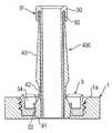
도 2는 도 1의 본 플레이트 조립체의 플레이트 부재에 마련된 홀의 대략적인 단면도이다.
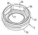
도 3은 플레이트 부재의 홀에 마련된 삽입부의 위에서 본 사시도이다.
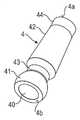
도 4는 도 1의 플레이트 부재에 마련된 안내 부재의 사시도이다.
도 5는 도 2에 도시된 홀으로 도 3에 도시된 삽입부를 삽입하기 위한 툴(tool)의 측면 사시도이다.
도 6은 도 3의 삽입부의 중심축을 포함하는 평면을 따른 대략적인 단면도이다.
도 7은 상기 툴, 상기 삽입부, 상기 안내 부재 및 상기 홀의 대략적인 단면 분해도이다.
도 8은 안내 부재를 통해 안내되는 드릴 날을 가지는 도 1 내지 도 7의 툴, 및 안내 부재 및 삽입부를 가지는 플레이트 부재의 대략적인 단면도이다.
도 9는 피봇되는 위치에서 상기 안내 부재를 통해 안내되는 드릴 날 및 안내 부재를 가지는 삽입부 및 홀을 가지는 플레이트 부재의 대략적인 단면도이다.
도 10은 잠금 요소 및 삽입된 접골나사를 가지는 본 플레이트 부재의 대략적인 단면도이다.
도 11은 사시도에 있어서의 안내 부재의 제2실시예이다.
도 12는 도 11의 안내 부재의 대략적인 단면도이고, 상기 단면은 안내 부재의 중심축을 포함하는 평면 내에 있다.
도 13은 도 11의 안내 부재에 연결되는 부싱의 사시도이다.
도 14는 도 13의 부싱의 대략적인 단면도이고, 상기 단면은 상기 중심축을 포함하는 평면 내에 있다.
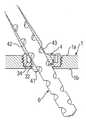
도 15는 안내 부재를 통해 안내되는 안내 배선 및 도 13 및 도 14의 부싱이 마련된 안내 부재 및 삽입부를 가지는 플레이트 부재의 대략적인 단면도이다.
도 16은 제거된 삽입부 및 뼈에 이미 삽입된 안내 배선 및 부싱을 가지는 안내 부재 및 홀르 가지는 본 플레이트의 대략적인 단면도이다.
도 17은 도 13 내지 도 16에 도시된 부싱에 비해 보다 큰 내부 지름을 가지는 부싱, 삽입부, 안내 부재, 및 본 플레이트 부재를 가지는 뼈의 대략적인 단면도이다.
도 18은 안내 배선을 수용하기 위한 다른 실시예들의 안내 부재에 비해 보다 작은 내부 지름을 가지는 안내 부재 및 삽입부를 가지는 플레이트 부재의 대략적인 단면도이다.
도 19는 안내 부재 및 삽입부의 제3실시예의 하부조립체의 사시도이다.
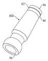
도 20은 안내 부재의 제3실시예의 사시도이다.
도 21은 수직 위치에 있어서의 부싱 및 제3실시예의 안내 부재를 가지는 삽입부 및 플레이트 부재의 대략적인 단면도이다.
도 22는 홀 내에 삽입부를 삽입하기 위한 툴의 대략적인 측면도이다.
도 23은 더 변형된 부싱, 안내 부재, 및 삽입부를 가지는 본 플레이트의 대략적인 단면 분해도이다.
도 24는 장착된 상태에 있는 도 23의 조립체의 대략적인 단면도이다.
도 25는 본 플레이트 조립체의 다른 실시예의 분해 사시도이다.
도 26은 K-배선 슬리브가 없는 도 25의 본 플레이트 조립체의 사시도이다.
도 27은 K-배선 슬리브가 있는 조립된 상태에 잇는 도 25의 조립체의 사시도이다.
도 28은 도 26의 본 플레이트 조립체의 대략적인 단면도이고, 상기 단면은 플레이트 부재의 홀의 중심축을 포함하는 평면 내에 있다.
도 29는 K-배선 슬리브를 가지는 도 27에 다른 조립된 상태에 있는 본 플레이트 조립체의 대략적인 단면도이다.
도 30은 본 플레이트 조립체의 다른 실시예의 분해 사시도이다.
도 31은 조립된 상태에 있는 도 30의 본 플레이트 조립체를 보여준다.
도 32는 도 30에 따른 본 플레이트 조립체의 삽입부의 위에서 본 사시도이다.1 is a perspective view of a bone plate assembly with guide members.
FIG. 2 is a schematic cross-sectional view of a hole provided in the plate member of the bone plate assembly of FIG. 1. FIG.
3 is a perspective view from above of the insertion portion provided in the hole of the plate member.
4 is a perspective view of a guide member provided in the plate member of FIG. 1.
5 is a side perspective view of a tool for inserting the insert shown in FIG. 3 into the hole shown in FIG.
FIG. 6 is a schematic cross-sectional view along a plane including a central axis of the insert of FIG. 3.
7 is a schematic cross-sectional exploded view of the tool, the insert, the guide member and the hole.
8 is a schematic cross-sectional view of the tool of FIGS. 1-7 with a drill edge guided through a guide member and a plate member with a guide member and an insert.
FIG. 9 is a schematic cross-sectional view of a plate member having an insert and a hole having a drill blade and a guide member guided through the guide member in a pivoted position.
10 is a schematic cross-sectional view of a bone plate member having a locking element and inserted screw.
11 is a second embodiment of a guide member in a perspective view.
FIG. 12 is a schematic cross-sectional view of the guide member of FIG. 11, wherein the cross section is in a plane including the central axis of the guide member.
13 is a perspective view of a bushing connected to the guide member of FIG. 11.
FIG. 14 is a schematic cross sectional view of the bushing of FIG. 13, the cross section being in a plane including the central axis. FIG.
15 is a schematic cross-sectional view of a plate member having guide wires guided through the guide members and guide members and inserts provided with bushings of FIGS. 13 and 14.
FIG. 16 is a schematic cross-sectional view of the bone plate with a guide member and a hole having guide wires and bushings already inserted into the removed insert and bone.
FIG. 17 is a schematic cross-sectional view of a bone having a bushing, insert, guide member, and bone plate member having a larger inner diameter as compared to the bushings shown in FIGS. 13-16.
18 is a schematic cross-sectional view of a plate member having a guide member and an insert having a smaller inner diameter as compared to the guide member of other embodiments for receiving guide wiring.
19 is a perspective view of the subassembly of the third embodiment of the guide member and the insert.
20 is a perspective view of a third embodiment of a guide member.
Fig. 21 is a schematic cross sectional view of the insert and plate member having the bushing in the vertical position and the guide member of the third embodiment.
22 is a schematic side view of a tool for inserting an insert into a hole.
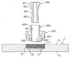
23 is a schematic cross-sectional exploded view of the bone plate with more deformed bushings, guide members, and inserts.
24 is a schematic cross-sectional view of the assembly of FIG. 23 in a mounted state.
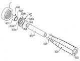
25 is an exploded perspective view of another embodiment of the present plate assembly.
FIG. 26 is a perspective view of the bone plate assembly of FIG. 25 without a K-wiring sleeve. FIG.
27 is a perspective view of the assembly of FIG. 25 in an assembled state with a K-wiring sleeve.
FIG. 28 is a schematic cross-sectional view of the bone plate assembly of FIG. 26, wherein the cross section is in a plane including the central axis of the hole of the plate member.
FIG. 29 is a schematic cross-sectional view of the bone plate assembly in another assembled state in FIG. 27 with a K-wire sleeve. FIG.
30 is an exploded perspective view of another embodiment of the present plate assembly.
FIG. 31 shows the bone plate assembly of FIG. 30 in an assembled state.
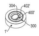
32 is a perspective view from above of the insert of the bone plate assembly according to FIG. 30.
본 플레이트 조립체의 제1실시예는 도 1 내지 도 9를 참조하여 설명될 것이다. 도 1에 도시된 바와 같이, 상기 본 플레이트 조립체는 이 실시예에 있어서 상측(top side, 1a) 및 하측(bottom side, 1b)을 가지는 대체적으로 긴 몸체인 플레이트 부재(1)를 포함한다. 복수의 홀들은 상기 상측(1a)으로부터 하측(1b)까지 상기 플레이트 부재를 관통해 연장된다. 상기 홀들의 갯수 및 배치는 상기 플레이트 부재(1)의 크기 및 형태에 따라 다양할 수 있다. 상기 홀들(2)은 상기 플레이트 부재(1)를 뼈 표면, 예를 들어 부러진 뼈 부분들 또는 척추뼈에 고정하기 위해 본 앵커들, 예를 들어 접골나사들을 수령하도록 되어 있다.A first embodiment of the present plate assembly will be described with reference to FIGS. 1 to 9. As shown in FIG. 1, the bone plate assembly comprises in this embodiment a
상기 홀들 안에, 도 1에 도시된 바와 같이 각각의 홀 안에, 삽입부(3)가 상기 홀(2)의 벽에 제거가능하게 연결될 수 있게 마련된다. 안내 부재(4)는 상기 삽입부(3) 내에 수령된다. 도시된 이 실시예에 있어서, 복수의 안내 부재들은 각각의 삽입부들(3) 내에 수령된다. 홀들(2)을 가지는 상기 플레이트 부재 내에 마련되는 안내 부재들(4)을 가지는 삽입부들(3)의 갯수는 본 플레이트 조립체에 대한 실제 요구사항들에 따라 다양할 수 있다.In the holes, in each hole as shown in FIG. 1, an
도 2에 도시된 바와 같이, 상기 홀(2)은 상기 하측(1b)을 향하는 개구부(20)와 피봇가능한 방식으로 접골나사의 머리를 수령하기 위해 상기 개구부(20)에 인접하는 속이 빈 안착부 부분(21)을 포함한다. 상기 안착부 부분(21)과 상기 상측(1a) 사이에 내부적으로 나사산 있는 부분(23)을 가지는 원통형 구멍(bore, 22)이 마련된다. 상기 구멍(22)의 내부 지름은 상기 안착부 부분(21)의 내부 지름보다 크다. 상기 나사산 있는 부분(23)은 예를 들어, 측정 나사산(metric thread) 같은, 어떠한 나사산 형태든 가질 수 있다. 상기 나사산은 또한 상기 플레이트 부재가 얇은 두께로 설계되는 것을 허용하기 위해 2-시작 나사산(two-start)일 수 있다.As shown in FIG. 2, the
특히 도 1 및 도 6에 도시된 바와 같이, 상기 삽입부(3)은 상측(3a) 및 하측(3b)을 가지고 또한 상기 상측(3a)과 상기 하측(3b) 사이의 전체 높이는 상기 삽입부가 상기 홀(2)의 상기 구멍(22)으로 삽입될 때 그 상측(3a)은 상기 플레이트 부재(1)의 상기 상측(1a)과 실질적으로 같은 높이인 실질적으로 원통형 조각이다. 상기 삽입부(3)는 상기 홀(2)의 상기 나사산 있는 부분(23)과 함께 협력하는 외부에 나사산 있는 표면 부분(30)을 가진다. 그 중심에, 상기 삽입부(3)가 상기 하측(3b)으로의 방향으로 구형 세그먼트-형상 부분(32)으로 넓어지는 동심축 관통공(31)을 가진다. 상기 구형-세그먼트 형상 부분(32)은 원뿔 모양으로 넓어지는 부분(33)이 상기 하측(3b)까지 계속된다.In particular, as shown in FIGS. 1 and 6, the
상기 삽입부의 상측(3a)에는, 도 5에 도시된 바와 같이, 툴(5)과 맞물리기 위한 오목부(34)가 마련된다. 도시된 실시예에 있어서 상기 오목부(34)는 외부가 육각형 형상인 외형을 가진다. 하지만, 툴과 맞물림을 허용하는 다른 어떠한 오목부, 예를 들어 다른 다각형 형상 오목부 또는 별 모양 오목부 등도 생각할 수 있다. 상기 오목부의 내부 외형은 실질적으로 원통형이고, 상기 오목부의 내부 벽은 절단되어 상기 오목부의 외부 벽보다 실질적으로 작은 높이의 환형 테두리(35)가 잔존한다.On the
특히 도 4 및 도 7에 도시된 바와 같이, 상기 안내 부재(4)는 상단(4a) 및 하단(4b) 및 상기 상단(4a)으로부터 상기 하단(4b)까지 연장되는 안내 채널(40)을 가지는 실질적으로 회전 대칭 조각으로 형성된다. 제1실시예에 있어서, 상기 안내 부재(40)는 도 8 및 도 9에 도시된 바와 같이 드릴 날(6)이 관통하는 것을 허용하도록 구성되는 지름을 가진다. 상기 안내 부재(4)는 그 지름이 상기 하단(4b)을 향해 증가하도록 방향지어지는 구형-형상 외부 표면을 가지는 부분(41)을 포함한다. 상기 안내 부재는 상기 안내 부재(4)가 상기 홀(2)에 삽입될 때 상기 플레이트 부재(1)로부터 연장되고 또한 상기 안내 부재를 잡고 방향짓기 위해 제공될 수 있는 축 부분(shaft portion, 42)를 더 가진다. 상기 축 부분(42)은 작은 원뿔 각도를 가지고 상기 상단(4a)을 향해 가늘어지는, 실질적으로 원뿔 모양으로 가늘어지는 외부 표면을 가진다. 상기 원뿔 모양 외부 표면은 단지 예시일 뿐 원통형 또는 다각형 형상 설계와 같이, 상기 축 부분(42)의 외부 표면의 다른 설계를 생각할 수 있음을 이해해야 한다. 상기 축 부분(42)의 최대 외부 지름은 상기 구형-형상 부분(41)의 최대 외부 지름보다 작다. 상기 축 부분(42)과 상기 구형-형상 부분(41) 사이에 상기 구형-형상 부분(41) 및 상기 축 부분(42)의 외부 지름과 비교했을 때 감소된 지름을 가지는 넥 부분(neck portion, 43)이 마련된다. 상기 넥 부분(43)의 상기 축 부분(42) 및/또는 상기 구형-형상 부분(41)으로의 전이는 점진적이거나 또는 갑자기 발생할 수 있다. 상기 상단(4a)에 인접하여, 원통형 부분(44)이 마련될 수 있다.4 and 7, the
상기 안내 부재(4) 및 상기 삽입부(3)의 크기는 특히 도 7에 도시된 바와 같이, 상기 안내 부재(4)가 상기 하측(3b)으로부터 상기 삽입부(3)로 도입될 수 있을 정도이다. 상기 축 부분(42)은 상기 안내 부재(4)의 상기 구형-형상 부분(41)이 상기 관통공의 상기 구형-세그먼트 형상 부분(32)에 안착할 때까지 상기 관통공(31)을 통해 관통된다. 도 8 및 도 9에 도시된 바와 같이, 상기 안내 부재(4)의 상기 구형-형상 부분(41)은 상기 관통공(31)을 통해 부분적으로 연장될 수 있어 상기 구형-형상 부분(41)은 상기 삽입부(3) 내에 약간 고정될 수 있다. 상기 안내 부재(4)는 상기 삽입부(3) 안에서 피봇가능하다. 상기 감소된 지름을 가지는 상기 넥 부분(43)은 60°까지 이르는 큰 운동 범위를 가지고 상기 안내 부재(4)의 피봇 운동을 허용하는 상기 삽입부 안에 상기 오목부(34)에 의해 마련되는 공간과 마주친다.The size of the
상기 삽입부(3)를 상기 홀(2) 안으로 삽입하는 데 사용될 수 있는 상기 툴(5)은 도 5에 도시되어 있다. 이것은 상단(5a) 및 하단(5b), 상기 하단(5b)에 있는 맞물림 부분(50) 및 핸들로서 기능하는 상단 부분(51)을 포함한다. 상기 맞물림 부분(50)은 그 지름이 상기 삽입부(3)의 테두리(35)의 외부 지름보다 큰 동심축 구멍(52)을 포함한다. 상기 맞물림 부분(50)의 외부 벽은 상기 삽입부의 상기 오목부(34)의 외형에 맞도록 되어 있고, 본 실시예에서 도시된 바는, 육각 형상이다. 상기 상단 부분(51)은 드릴 날 또는 다른 도구가 이를 관통하는 것을 허용하는 관통 구멍(through bore, 53)을 포함한다.The
본 플레이트 조립체의 요소들은 예를 들어 스테인레스 스틸 또는 티타늄과 같은 몸체 호환가능한 금속, 또는 Ni-Ti-합금, 예를 들어 니티놀(Nitinol)과 같은 몸체 호환가능한 금속 합금과 같은 몸체 호환가능한 물질, 또는 예를 들어 의료등급 PEEK 같은 몸체 호환가능한 플라스틱 물질 또는 그 조합으로 만들어진다. 예를 들어, 상기 플레이트 부재, 상기 삽입부들 및 상기 안내 부재들은 동일하거나 또는 다른 물질들로 만들어질 수 있다.The elements of the plate assembly may be, for example, a body compatible metal such as stainless steel or titanium, or a body compatible material such as a body compatible metal alloy such as Ni-Ti-alloy, for example Nitinol, or For example, it is made of body compatible plastic materials such as medical grade PEEK or combinations thereof. For example, the plate member, the inserts and the guide member may be made of the same or different materials.
안내 부재를 가지는 본 플레이트 조립체의 사용은 도 7 내지 도 10을 참조하여 설명될 것이다. 먼저, 상기 안내 부재(4)는 그것이 상기 삽입부의 상기 구형-형상 부분(32) 안에 상기 구형-형상 부분(41)과 함께 안착될 때까지 상기 하측(3b)으로부터 상기 삽입부(3)로 도입된다. 그후, 상기 안내 부재(4)와 함께 상기 삽입부는 상기 툴(5)을 이용해 홀(2)에 나사고정된다. 상기 삽입부(3)가 상기 홀(2) 안에 고정될 때 약간의 압력이 상기 삽입부 및 플레이트 부재에 의해 상기 안내 부재(4)에 가해져 상기 안내 부재(4)는 상기 삽입부 내에 약간 고정된다. 뼈에 준비되어야 하는 상기 홀이 상기 플레이트 부재(1)에 수직하는 홀이면, 상기 안내 부재는 도 8에 도시된 바와 같이 똑바른 위치로 고정된다. 이 경우에 있어서, 상기 툴은 상기 삽입부(3) 안에 맞물린 채 남아있을 수 있고 상기 드릴 날(6)이 삽입될 수 있고 상기 툴(5) 및 상기 안내 부재(4)를 관통한다. 상기 툴(5)은 상기 드릴 날(6)을 똑바로 유지하기 위해 지지대로 사용될 수 있다.The use of the present plate assembly with a guide member will be described with reference to FIGS. 7 to 10. First, the
경사진 홀(inclined hole)이 뼈 안에 준비되어야 하면, 상기 툴(5)은 제거되고 상기 안내 부재(4)은 원하는 각도 위치가 획득될 때까지 피봇된다. 그후, 도 9에 도시된 바와 같이, 상기 드릴 날(6)은 상기 안내 부재(4)의 안내 채널을 관통하고 상기 홀은 천공(drill)된다.If an inclined hole has to be prepared in the bone, the
상기 홀이 천공된 후, 상기 드릴 날은 상기 홀로부터 제거되고 상기 툴(5)은 상기 삽입부를 나사결합하는 데 사용된다. 상기 툴(5)의 설계 때문에 상기 안내 부재(4)는 상기 안내 부재와 함께 상기 삽입부를 제거하는 것을 허용하는 상기 플레이트 부재에 대해 다시 똑바른 위치로 다시 피봇된다.After the hole is drilled, the drill blade is removed from the hole and the
그후, 도 10에 도시된 바와 같이, 구형-형상 헤드(70)를 가지는 접골나사(7)가 상기 플레이트 부재 안의 상기 홀(2)에 삽입되고 상기 뼈 안의 준비된 홀에 나사결합된다. 잠금 부재(8)는 그후 상기 홀(2) 안에 상기 헤드(70)를 잠그기 위해 구형으로 오목한 부분(80) 안의 상기 헤드(70)에 가해지는 상기 홀(2) 안에 나사결합된다.Then, as shown in FIG. 10, a
상기 안내 부재의 제2실시예는 도 11 내지 도 16을 참조하여 설명될 것이다. 상기 제1실시예에서와 동일하거나 유사한 부품들 또는 부분들은 동일한 참조부호들에 의해 지시되고 그 설명을 반복하지 않을 것이다. 상기 안내 부재(400)는 상기 상단(4a)으로부터 소정 거리에 원형 홈(circular groove, 401)을 가진다는 점에 있어서 상기 안내 부재(4)와 다르다. 상기 홈은 상기 원통형 부분(44)에 마련되고 도 13에 도시된 부싱(9)의 고정 요소에 맞물리기 위해 제공된다. 상기 부싱(9)은 상단(9a) 및 하단(9b)을 가지는 원통형 튜브(cylindrical tube)이고, 이때 상기 원통(cylinder)의 외부 지름은 도 12에 도시된 바와 같이 상기 안내 채널(40)의 내부 지름보다 약간 작아서 상기 부싱(9)이 상기 안내 부재(400)로 도입될 수 있다. 상기 부싱(9)의 내부 지름은 도 15 및 도 16에 도시된 바와 같이, 안내 배선, 예를 들어, K-배선(10)이 이를 관통해 안내되도록 허용할 수 있다. 상기 부싱(9)은 그 상단(9a)에 칼라(collar, 90)를 가진다. 상기 칼라(90)는 상기 부싱(9)이 상기 안내 부재(400)의 상기 원통형 부분(44)을 따라 상기 안내 부재의 외부 표면으로부터 소정 거리에서 상기 안내 부재(400)에 삽입될 때 상기 부싱에 연결되고 연장된다. 상기 부싱(9)의 몸체와 함께 상기 칼라(90)의 상기 연결 부분(90a)은 상기 안내 부재(400)로 상기 부싱의 삽입을 위한 정지부를 형성한다.A second embodiment of the guide member will be described with reference to FIGS. 11 to 16. Parts or parts that are the same or similar to those in the first embodiment will be denoted by the same reference numerals and will not repeat the description. The
상기 부싱(9)은 맞물림 요소들(91)을 이용해 고정되는데, 이것은 본 실시예에 있어서 상기 칼라(90) 및 맞물림 홈(401)을 관통해 연장되는 핀들(91)이다. 상기 부싱을 상기 안내 부재에 제거가능하게 고정하기 위한 많은 가능성들이 생각되어질 수 있다. 예를 들어, 상기 안내 부재 및 상기 부싱은 상기 안내 부재에 스냅연결되는 칼라 대신 탄성 플랜지(resilient tongues)에 의해 또는 주름(crimping)에 의해 만들어진 돌기(projection) 및 오목부(recess)에 의해 함께 고정될 수 있다. 또한, 상기 부싱은 상기 칼라(90)의 내측에 상기 안내 부재 상의 대응하는 나사산에 맞물리는 나사산을 가질 수 있다.The
사용시, 상기 부싱은 상기 안내 부재에 삽입되는데, 이것은 상기 홀(2) 안에 제공된 상기 삽입부(3)에 상기 안내 부재(400)가 이미 삽입된 때조차도 수행될 수 있다. 그후, 안내 배선이 상기 안내 부재(400)를 관통하고 상기 안내 부재(400)는 원하는 위치로 피봇된다. 상기 부싱(9)이 상기 안내 부재 상에 일시적으로 고정되기 때문에, 이것은 넘어질 수 없다. 상기 안내 배선을 가지고, 예를 들어 제1뼈조각이 고정될 수 있다. 필요하다면, 상기 안내 배선은 도 15에 도시된 바와 같이, 경사진 방향으로 뼈 안에 도입될 수 있다.In use, the bushing is inserted into the guide member, which can be done even when the
그후, 상기 삽입부(3)는 상기 안내 배선이 상기 뼈 안에 남아있는 동안 제거될 수 있다. 이것은 상기 본 플레이 표면에 대하여 수직한 위치에 대한 도 16에 도시되어 있다. 도 16에 도시된 상태에서, 뼈 안의 홀은 삽관형 드릴(cannulated drill)을 이용해 천공될 수 있다. 그후, 상기 안내 부재(400)는 제거되고 상기 안내 배선에 이어 삽관형 나사가 삽입될 수 있다. 마지막으로, 상기 안내 배선이 제거되고 도 10에 도시된 바와 같이 상기 잠금 부재(8)가 상기 접골나사를 잠그기 위해 상기 홀(2)에 나사결합된다.The
도 17은 제2실시예의 다른 변형을 보여준다. 이것은 이전에 설명된 실시예와 상기 부싱(9')의 내부 지름이 이전 실시예의 상기 부싱(9)보다 크다는 점만이 다르다. 또한 상기 핀들(91) 대신 돌출부(noses, 92)가 마련되는데, 이것은 홈-형태(groove-shaped)일 수 있거나 또는 다른 형태를 가질 수 있는 상기 부싱(9')의 외부 표면의 대응하는 맞물림 부분들에 스냅결합될 수 있다. 다른 내부 지름을 가지는 몇 개의 부싱들이 상기 안내 채널(40)의 지름이 특정 도구 또는 드릴에 맞도록 허용하기 위해 제공될 수 있다.17 shows another variation of the second embodiment. This differs only from the previously described embodiment in that the inner diameter of the bushing 9 'is larger than the
이전 실시예들의 다른 변형이 도 18에 도시되어 있다. 상기 안내 부재(400')는 그 지름이 이전 실시예들의 안내 채널(40)의 지름보다 작고 안내 배선(10)이 이를 관통해 안내되는 것을 허용하도록 구성된 안내 채널(40')을 가진다. 이 경우에 있어서, 상기 안내 부재(4')를 이용해 상기 안내 배선(10)을 가지고 상기 접골나사의 원하는 위치를 미리 정의하고 이후 상기 안내 배선이 뼈에 남아있는 동안 상기 안내 부재(4')와 함께 상기 삽입부(3)를 제거하는 것이 가능하다. 그후 홀을 미리 천공하지 않고 뼈 안에 안내 배선에 이어 삽관형 나사를 나사결합하는 것이 가능하다.Another variation of the previous embodiments is shown in FIG. 18. The
도 19는 제3실시예의 삽입부(3000)와 안내 부재(4000) 각각의 가능한 하부조립체를 보여준다. 이하에서 설명하는 바와 같이, 상기 안내 부재(4000)는 상기 삽입부(3000)에 탁찰가능하게 부착될 수 있다.19 shows a possible subassembly of each of the
상기 삽입부(3000)의 구조는 실질적으로 다른 실시예들의 삽입부의 구조와 동일하다. 하지만, 상기 툴(5)과의 맞물림을 위해 상기 오목부(34) 대신, 상기 삽입부(3000)에는 그 둘레에 육각형(hexagon, 3001)이 마련되는데, 이후에 설명하는 툴에 맞도록 되어 있다. 육각형 소켓을 가지는 오목부(34) 대신, 상기 삽입부(3000)에는 상기 안내 부재의 피봇 운동을 위한 공간을 제공하기 위해 가늘어지는 오목부(3002) 등이 마련된다. 이전에 설명된 삽입부(3)의 툴에 맞물리는 상기 오목부의 육각형 소켓(34)은 상기 삽입부(3000)의 둘레에 육각형(3001)에 의해 대체된다. 육각형 대신 예를 들어 다른 다각형 구조와 같은 다른 외부 맞물림 구조가 사용될 수 있음에 주목해야 한다.The structure of the inserting
또한, 도 20에 도시된, 상기 안내 부재(4000)는 다른 실시예들의 안내 부재들의 구조와 실질적으로 동일하고 또한 적합하다면 동일한 참조부호들이 사용된다. 하지만, 상기 안내 부재(4000)는 상기 하단(4b)으로부터 상기 축 부분(42)을 향하는 방향으로 연장되는 슬롯들(4002)이 마련된 구형-세그먼트 형상 제1부분(4001)을 가진다. 이 방향에서, 상기 구형-세그먼트 형상 제1부분(4001)의 구의 중심 주위까지 상기 슬롯들이 형성된다. 이러한 슬롯들(4002)의 마련은 방사상 힘들(radial forces)이 하부 영역에 있는 상기 구형-세그먼트 제1부분(4001) 상에 가해질 때 상기 구형-세그먼트 제1부분(4001)이 어느 정도 플렉시블하게 해준다.In addition, the
나아가, 상기 구형-세그먼트 제1부분(4001)에는 각이 있는 편평한 부분(4003)이 마련된다. 상기 각이 있는 편평한 부분(4003)은 상기 하단(4b)으로부터 상기 구형-세그먼트 제1부분(4001)의 외부 표면으로 연장된다. 상기 하단(4b)과 상기 각이 있는 편평한 부분(4003) 사이의 각도는 대략 30°이다. 다른 실시예에 있어서, 이 각도는 주변환경 구조에 따라 달라질 수 있다. 상기 각이 있는 편평한 부분(4003)은 상기 안내 부재(4000)가 틸트될 때 상기 플레이트 부재(1)가 아래의 뼈에 완전히 접촉할 때조차 상기 안내 부재(4000)와 뼈 사이의 접촉을 방지하기 위해 제공된다. 뼈와 상기 안내 부재 사이에 접촉이 발생하면, 뼈 괴사(bone necrosis)의 위험이 있을 수 있다. 이러한 설계로 인해, 상기 안내 부재(4000)와 뼈 사이에 대략 1mm의 갭이 가능하다.Further, the spherical-segment
상기 상단(4a)에, 상기 안내 부재(4000)에는 식별 노치(identification notch, 4004)가 마련된다. 상기 식별 노치(4004)는 상기 상단(4a)으로부터 상기 구형-세그먼트 제1부분(4001)을 향한 방향으로 연장된다. 이 식별 노치(4004)는 상기 안내 부재(4000)의 상기 하단(4b)에서 상기 각이 있는 편평한 부분(4003)에 정렬된다. 그러므로, 상기 안내 부재가 상기 플레이트의 상기 홀(2) 안에 장착되기 때문에 상기 각이 있는 편평한 부분(4003)을 볼 수 없을 때조차 상기 안내 부재(4000)의 축 방향(axial orientation) 및 상기 각이 있는 편평한 부분(4003)의 위치를 아는 것이 가능하고, 또한 상기 안내 부재(4000)를 회전시켜 뼈에 접촉하지 않고 원하는 틸트 각도의 방향이 조절될 수 있다. 상기 식별 노치의 기능은 상기 각이 있는 편평한 부분(4003)의 방향을 인식하는 것이 가능하다면 다른 방식 또한 다른 위치에 구축될 수 있다. 인쇄된 표시들 또는 상승된 표시들과 같은 다른 타입들의 식별 표시들이 사용될 수 있다.At the
도 21에 도시된 바와 같이, 상기 삽입부(3000)에는 구형-형상 세그먼트 부분(3003)이 상기 하측(3b)을 향하는 방향으로 상기 가늘어지는 오목부(3002) 아래에 마련된다. 상기 구형-형상 세그먼트 부분(3003)은 상기 하측(3b)을 향하는 방향으로, 상기 구형-형상 세그먼트 부분(3003)의 구의 주심을 넘어 약간 연장된, 증가된 볼 접촉 영역을 가진다.As shown in FIG. 21, the
그러므로, 상기 구형-형상 세그먼트 부분(3003)과 상기 안내 부재(4000)의 상기 구형-형상 제1부분(4001) 사이에 안성맞춤 연결(form fit connection)이 존재한다. 하지만, 상기 슬롯들(4002) 때문에 상기 구형-형상 제1부분(4001)의 탄성 특성으로 인해, 상기 구형-형상 제1부분(4001)을 상기 구형-형상 세그먼트 부분(3003)으로 클릭하는 것에 의해 상기 구형-형상 제1부분(4001)을 상기 구형-형상 세그먼트 부분(3003)에 제거가능하게 부착하는 것이 가능하다.Therefore, there is a form fit connection between the spherical-shaped
상기 안내 부재들의 구형-형상 제1부분이 상기 삽입부(3)와 상기 플레이트 부재(1)의 안착부 부분(21) 사이에 고정되는 이전의 실시예들과는 다르게, 상기 안내 부재(4000)의 상기 구형-형상 제1부분(4001)은 단지 상기 구형-형상 제1부분(4001)과 상기 구형-형상 세그먼트 부분(3003) 사이의 마찰력 및 안성맞춤 연결에 의해서만 고정된다. 상기 삽입부가 조여질 때, 상기 삽입부의 상기 하측(3b)은 상기 구형-형상 세그먼트 부분(3003)과 상기 구형-형상 제1부분(4001) 사이의 고정력(clamping force)을 변경하지 않고 상기 홀(2)의 바닥과 맞붙는다. 그러므로, 상기 삽입부(3000)가 단단히 조여진다면, 상기 안내 부재(4000)를 틸트하는 것이 가능해지고, 상기 고정력은 상기 조임 토크(tightening torque)에 따라 달라지지 않는다.Unlike the previous embodiments in which the spherical-shaped first portion of the guide members is fixed between the
나아가, 도 21에서는 상기 툴이 상기 육각형(3001)에 맞물릴 수 있도록 상기 육각형(3001)이 상기 플레이트 부재(10) 외부에 위치됨을 볼 수 있다.Furthermore, in FIG. 21, it can be seen that the
부싱(9000)이 상기 안내 부재(400)에 스냅연결되는 상기 부싱(90)과 유사하게 상기 안내 부재(4000) 상에 스냅연결된다. 하지만, 상기 부싱 또한 다른 방식으로 부착될 수 있다. 상기 부싱(9000)에는 약간 가늘어지는 형상을 가지는 채널(9002)이 마련된다. 상기 채널(9002)의 보다 작은 지름은 상기 부싱(9000)의 상단(9001)에 위치된다. 상기 부싱(9)의 보다 작은 내부 지름은 안내 배선, 예를 들어 K-배선이 이를 관통해 안내되는 것을 허용한다. 하지만, 장애물들이 일정한 내부 지름을 가지는 채널 안에 존재하면, 상기 안내 배선은 상기 채널 안에 고정될 수 있는데, 이것은 이 실시예에서 상기 채널의 가늘어지는 형상으로 인해 방지된다.A
도 22는 상기 삽입부(3000)를 상기 홀(2) 안으로 삽입하기 위한 툴(5000)을 보여준다. 상기 툴(5000)은 상기 삽입부(3000)의 상기 육각형(3001)에 적합한 단면을 가지는 오목부(5001)를 포함한다. 상기 상단(5a)을 향하는 방향으로 상기 오목부(5001)의 깊이는 상기 육각형(3001)의 높이보다 더 크다. 나아가, 상기 오목부(5001)의 깊이는 상기 안내 부재(4000)가 전체 운동 범위 안에서 틸트되어 있거나 또는 똑바른 위치에 있다면 상기 삽입부(3000) 및 상기 안내 부재(4000)를 수용하도록 되어 있다. 그러므로, 상기 안내 부재(4000)의 각 위치(angular position)에 독립적으로 상기 삽입부(3000)를 삽입하거나 제거하기 위해 상기 툴(5000)을 사용하는 것이 가능하다.22 shows a
사용시, 상기 안내 부재(4000)는 상기 삽입부(300) 내로 클릭되어, 도 19에 도시된 바와 같은 하부조립체를 형성한다. 그후, 다른 실시예들에서와 같이, 상기 안내 부재를 가지는 상기 삽입부(3000)는 상기 툴(5000)에 의해 상기 홀(2) 안으로 나사결합된다. 상기 안내 부재(4000)는 마찰력에 의해 고정되어, 그 틸트 각도가 미리 조정될 수 있다. 상기 틸트되거나 또는 똑바른 안내 부재(4000)는 그 깊이로 인해, 상기 안내 부재(4000)의 전체 운동 범위 안에서 틸트되거나 또는 똑바른 어떠한 위치들에서도 상기 툴의 오목부(5001)가 상기 삽입부(3000) 및 상기 안내 부재(4000)를 수용할 수 있기 때문에 미리 설정된 각 위치에 고정될 수 있다.In use, the
그후, 상기 툴(5000)이 제거되고, 원한다면, 상기 안내 부재(4000)의 틸트 각도가 조정된다. 연이어, 상기 드릴 칼이 상기 안내 부재(4000)의 안내 채널을 관통하고 상기 홀이 천공된다.The
상기 홀이 천공된 후, 상기 드릴 날이 상기 홀로부터 제거되고 상기 툴(5000)은 상기 삽입부를 나사결합하기 위해 사용된다. 상기 툴(5000)의 설계 때문에, 상기 안내 부재(4000)는 똑바른 위치로 다시 피봇될 수 없어 삽관형 나사 또는 다른 장치의 사용이 필요한 경우 안내 배선이 뼈 안에 머문다면 상기 안내 부재(4000)를 제거하는 것이 가능하다.After the hole is drilled, the drill blade is removed from the hole and the
다른 실시예들의 본 플레이 조립체에 견줄 만한 다른 용법이 있다.There are other uses comparable to the present play assembly of other embodiments.
다른 종류의 부싱들 및 다른 내부 지름들을 가지는 다른 안내 부재들을 제공함으로써 외과의사가 매우 다양한 방식으로 절차들을 적용하도록 허용하는, 모듈화된 시스템이 획득될 수 있다.By providing different kinds of bushings and other guide members having different inner diameters, a modular system can be obtained that allows the surgeon to apply the procedures in a wide variety of ways.
다른 변형된 부싱(900)이 제3실시예의 상기 안내 부재(4000) 및 상기 삽입부(3000)와 함께 도 23 및 도 24에 도시되어 있다. 하지만, 상기 부싱(900)은 다른 안내 부재 및 설명된 다른 실시예들의 삽입과 함께 사용될 수 있음에 유의해야 한다. 상기 부싱(900)은 상기 안내 채널(40)의 내부 지름보다 큰 외부 지름을 가지는 제1부분(901)을 가진다. 상기 제1부분은 상기 부싱이 상기 안내 채널(40) 안의 마찰에 의해 고정될 정도의 외부 지름 크기를 가지는 제2부분(902)에 앞선다. 제3부분(903)은 상기 안내 채널의 내부 지름보다 작은 외부 지름을 가지고 뒤따를 수 있고 제4부분(904)은 상기 안내 채널(40)의 내부 지름에 비해 좀 더 작은 외부 지름을 가진다. 상기 부분들의 숫자는 변경될 수 있다. 하지만. 상부의 두꺼운 제1부분은 상기 부싱의 삽입을 한정하기 위한 정지부를 제공한다. 상기 부싱의 내부 지름은 드릴 날의 도입을 허용하도록 구성되거나 또는 안내 배선 또는 다른 도구의 도입을 허용하도록 구성된다.Another modified
상기 부싱(900)은 제조하기 쉽다.The
상기에서 설명한 실시예들의 다른 변형물들 및 변경물들이 생성될 수 있다. 예를 들어, 상기 삽입부와 상기 플레이트 부재 사이에 연결은 예를 들어 총검 연결(bayonet connection)과 같이, 다른 해제가능한 연결일 수 있다. 상기 안내 부재의 형태는 달라질 수 있다. 예를 들어, 상기 축 부분은 도시된 실시예서와 같이 더 길거나 더 짧을 수 있다.Other variations and modifications of the embodiments described above can be made. For example, the connection between the insert and the plate member may be another releasable connection, for example a bayonet connection. The shape of the guide member may vary. For example, the shaft portion can be longer or shorter as in the illustrated embodiment.
일반적으로, 상기 삽입부에는 예를 들어 그 주변에 드라이버(screwdriver)를 위한 육각형(3001)을 가지고, 맞물림 부분이 마련될 수 있다.In general, the insert has, for example, a hexagonal 3001 for a screwdriver around it, and an engagement portion can be provided.
일반적으로, 상기 안내 부재(400, 4000)에는 주변 홈(circumferential groove, 401)이 마련되어 있고, 상기 부싱은 상기 홈(401)으로 스냅결합될 수 있다.In general, a
일반적으로, 상기 부싱(9000)에는 더 작은 내부 지름이 상기 부싱(9000)의 상단(9001)에 위치하는 약간 가늘어지는 형태를 가지는 채널(2002)이 마련될 수 있다.In general, the
본 앵커로서, 접골나사들, 접골못들 등과 같은 모든 종류의 본 앵커들이 사용될 수 있다.As the bone anchor, all kinds of bone anchors such as bone screws, nails and the like can be used.
도 25 내지 도 29를 참조하면, 본 플레이트 조립체의 다른 실시예가 도시되어 있다. 상기 플레이트 부재(1')가 원형 플레이트 부재로서 단순한 방식으로 도시되어 있다. 하지만, 상기 플레이트 부재(1')는 예를 들어 도 1에 도시된 형태를 포함하는 어떠한 형태라도 가질 수 있다. 상기 플레이트 부재(1')는 상측(1a') 및 하측(1b'), 및 상기 상측(1a')으로부터 상기 하측(1b')까지 연장되는 홀(2')을 가진다. 이전 실시예들에서와 같이, 상기 홀(2')은 상기 하측(1b')을 향하는 개구부(20') 및 상기 개구부(20')에 인접하는 속이 빈 안착부 부분(21')을 포함한다. 상기 안착부 부분(21')과 상기 상측(1a') 사이에 내부적으로 나사산 있는 부분(23')을 가지는 원통형 구멍(22')이 마련된다. 상기 구멍(22')은 이전의 실시예들의 구멍(22)보다 깊지 않고 상기 속이 빈 안착부 부분(21')은 이전의 실시예들과 비교하면 축 방향으로 더 크다. 상기 안착부 부분(21')은 속이 빈 구형 세그먼트 형상을 가진다.25-29, another embodiment of the present plate assembly is shown. The
이 실시예의 상기 삽입부(300)는 상측(300a) 및 하측(300b), 및 상기 삽입부(300)가 상기 홀(2') 안에 있을 때 상기 상측(300a)은 상기 플레이트 부재(1')의 상기 상측(1a')과 실질적으로 같은 높이로 상기 상측(300a)과 상기 하측(300b) 사이의 전체 높이를 가지는 실질적으로 회전 대칭 조각이다. 상기 삽입부는 상기 홀(2')의 상기 나사산 있는 부분(23')과 협력하는 외부에 나사산 있는 표면 부분(300c)을 더 가진다. 상기 하측(300b)에 인접하여, 속이 빈 구형 세그먼트-형상 부분(302)이 마련되는데, 이것은 상기 안착부 부분(21)에 맞는 형 외부 표면을 가가지고 구형-형상 내부 표면 부분은 이하에서 설명하는 안내 부재(400')를 수용한다. 상기 속이 빈 구형 세그먼트-형상 부분(302)은 축 방향으로 연장되는 적어도 하나, 바람직하게는 복수의 슬롯들(302a)로 슬롯되어 있다. 상기 슬롯들(302a)은 속이 빈 구형 세그먼트-형상 부분(302)이 방사상 방향으로 플렉시블하게 해준다. 이것은 상기 안내 부재(400')의 삽입을 용이하게 해준다.The
상기 삽입부(300)는 상기 상측(300a)에 인접하는 복수의 맞물림 부분들(304)을 더 포함하고, 상기 맞물림 부분들(304)은 툴(500)을 이용한 맞물림을 위해 제공된다.The
상기 안내 부재(400')는 상단(400a'), 하단(400b'), 상기 상단으로부터 상기 하단까지 연장되는 안내 채널(400c')을 가지는 실질적으로 회전 대칭 조각이다. 상기 안내 부재(400')는 상기 구형 부분의 최대 외부 지름을 포함하여 축 길이 넘어 연장되는 상기 하단(400b')에 인접하는 구형-형상 외부 표면 부분(401')을 더 가진다. 상기 구형-형상 외부 표면 부분(401')은 상기 삽입부(300)의 상기 속이 빈 구형 세그먼트-형상 부분(302)에 맞다. 상기 상단(400a')에 인접하여, 원통형 축 부분(402')이 마련되는데, 이것은 이전의 실시예들의 축 부분보다 짧고 상기 플레이트 부재(1')의 상기 상측(1a')으로부터 약간 돌출되거나 돌출되지 않는다. 상기 안재 부재(400')는 상기 상단(400a)으로부터 상기 하단(400b)까지 연장되는 안내 채널(400c')을 가진다.The guide member 400 'is a substantially rotationally symmetrical piece having an
부싱(900')이 마련되는데, 이것은 안내 부재(400')에 연결될 수 있다. 상기 부싱(900')은 상기 안내 채널(400c)의 상기 내부 지름보다 약간 작은 외부 지름을 가지는 제1부분(901')을 포함하여, 상기 부싱(900')은 상기 안내 부재(400')에 압입식 끼워맞춤(press-fit) 방식으로 연결될 수 있다. 상기 제1부분(901')에 인접하여, 제2부분(902')에는 상기 부싱(900')이 상기 안내 부재(400')에 연결될 때 상기 제2부분(902')의 외부 표면이 상기 안내 부재(400')의 축 부분(402')과 같은 높이가 되는 외부 지름이 마련된다. 상기 부싱(900')은 안내 배선, 예를 들어 K-배선이 이를 관통해 안내되도록 허용하는 지름 크기를 가지는 동심축 관통 채널(903')을 가진다.Bushing 900 'is provided, which may be connected to guide member 400'. The bushing 900 'includes a first portion 901' having an outer diameter slightly smaller than the inner diameter of the
상기 툴(500)은 상기 삽입부(300)의 상기 맞물림 부분들(304)에 맞물리는 맞물림 부분들(501)을 가지는 전면 부분(front portion)을 포함한다. 상기 툴(500)은 또한 그 지름이 상기 부싱(900')의 외부 지름보다 큰 동심축 관통 채널(502)을 포함한다.The
사용시, 상기 안내 부재(400')는 상기 삽입부(300)와 상기 부싱(900')과 함께 미리 조립될 수 있고 상기 툴(500)을 이용해 상기 플레이트 부재(1')로 함께 삽입된다. 상기 플레이트 부재(1')가 뼈 또는 빼 부분 또는 조각에 배치되기만 하면, 상기 부싱(900') 및 상기 안내 부재(400')을 관통해 뼈로 K-배선이 안내될 수 있다. 그후, 상기 삽입부(300)는 상기 안내 부재(400)와 상기 부싱(900')과 함께 제거될 수 있고 뼈 안의 홀은 삽관형 드릴로 천공될 수 있다. 그후, 삽관형 나사는 상기 안내 배선에 이어 삽입될 수 있다. 마지막으로, 상기 안내 배선이 제거되고 이전에 설명된 잠금 요소는 상기 접골나사를 잠그기 위해 상기 홀(2')로 나사결합된다. 설명된 실시예는 특히 MIS(minimally invasive surgery) 응용에 적합하다.In use, the
도 30 내지 도 32는 본 플레이트 조립체의 다른 실시예를 보여준다. 이전의 실시예와 동일한 부분들은 동일한 참조부호를 가지고 그 설명은 반복되지 않는다. 상기 삽입부(300')는 상기 나사산 있는 외부 표면 부분(300'c)과 상기 상측(300a') 사이에 툴(500')과 맞물리는 외부 표면에서 맞물림 부분들(304')을 가지는 원통형 부분(300d')을 가진다. 상기 툴(500')은 상기 삽입부(300')의 상기 맞물림 부분들(304')에 맞물리는 일 단의 내부 벽에 맞물림 부분을 가지는 동심축 관통 채널(502')를 가진다. 상기 안내 부재(400')는 이전 실시예와 비교하여 더 긴 축 부분(402'')을 가진다. 상기 부싱(900'')은 상기 축 부분(402'')에 삽입되는 더 긴 제1부분(901'')을 가진다. 이에 더하여, 상기 부싱(900'')은 상기 안내 부재(400'')의 상기 축 부분(402'')으로부터 돌출되는 제2부분(902'')을 포함한다. 조립된 상태에서, 도 31에 도시된 바와 같이, 상기 축 부분(402'') 및 상기 부싱의 상기 제2부분(902)은 상기 삽입부(300)로부터 또한 상기 플레이트 부재(1')의 상기 상단(1a')으로부터 돌출된다.30 to 32 show another embodiment of the present plate assembly. The same parts as in the previous embodiment have the same reference numerals and the description is not repeated. The insert 300 'is a cylindrical portion having engagement portions 304' at an outer surface that engages the tool 500 'between the threaded outer surface portion 300'c and the
상기 본 플레이트 조립체의 사용은 이전 실시에와 유사할 수 있다. 상기 안내 부재(400'')의 상기 긴 축 부분(402'') 및 상기 부싱(900'')의 상기 긴 제2부분(902'') 때문에, 상기 본 플레이트 조립체 또한 MIS 응용분야에 유용하다.The use of the bone plate assembly may be similar to the previous embodiment. Because of the
다른 실시예에서, 본 플레이트 조립체는 상측 및 하측, 상기 상측으로부터 상기 하측으로 연장되는 적어도 하나의 홀, 관통공을 가지고 상기 홀 안에 배치되는 삽입부, 및 상기 삽입부의 관통공 안에 제거가능하게 배치되는 안내 부재를 포함하고, 상기 안내 부재는 안내 채널 및 상기 관통공의 내부 벽 부분에 맞물리는 외부 표면 부분을 가지는 플레이트 부재를 포함한다. 이로써 상기 삽입부 내에서 상기 안내 부재의 피봇 운동이 허용된다. 상기 삽입부는 상기 안내 부재의 구형-형상 외부 표면 부분과 협력하는 구형-형상 내부 표면 부분을 가진다.In another embodiment, the bone plate assembly is removably disposed in the upper and lower portions, at least one hole extending from the upper side to the lower side, an insertion portion disposed in the hole with a through hole, and a through hole in the insertion portion. A guide member, the guide member comprising a plate member having a guide channel and an outer surface portion that engages an inner wall portion of the through hole. This allows the pivoting movement of the guide member in the insert. The insert has a spherical-shaped inner surface portion that cooperates with the spherical-shaped outer surface portion of the guide member.
또 다른 실시예에 있어서, 본 플레이트 조립체는 상측 및 하측을 가지는 플레이트 부재, 상기 상측으로부터 상기 하측까지 연장된 적어도 하나의 홀, 관통공을 가지고 상기 홀 내에 배치되는 삽입부, 및 상기 삽입부의 상기 관통공 내에 제거가능하게 배치되는 안내 부재를 포함하고, 상기 안내 부재는 안내 채널 및 상기 관통공의 내부 벽 부분에 맞물리는 외부 표면 부분을 가져서 상기 삽입부 내에서 상기 안내 부재의 피봇 움직임을 허용한다. 상기 본 플레이트 조립체는 상기 안내 부재의 상기 축 부분이 상기 삽입부의 상기 관통공을 통해 충분히 관통되도록 배치되고, 상기 안내 부재는 상기 관통공에 머문다.In yet another embodiment, the bone plate assembly includes a plate member having an upper side and a lower side, at least one hole extending from the upper side to the lower side, an insertion portion disposed in the hole with a through hole, and the penetration portion of the insertion portion. A guide member removably disposed in the ball, the guide member having a guide channel and an outer surface portion that engages the inner wall portion of the through hole to allow pivotal movement of the guide member within the insert. The bone plate assembly is arranged such that the shaft portion of the guide member is sufficiently penetrated through the through hole of the insertion portion, and the guide member stays in the through hole.
또 다른 실시예에 있어서, 본 플레이트 조립체는 상측 및 하측을 가지는 플레이트 부재, 상기 상측으로부터 상기 하측까지 연장된 적어도 하나의 홀, 관통공을 가지고 상기 홀 내에 배치되는 삽입부, 및 상기 삽입부의 상기 관통공 내에 제거가능하게 배치되는 안내 부재를 포함하고, 상기 안내 부재는 안내 채널 및 상기 관통공의 내부 벽 부분에 맞물리는 외부 표면 부분을 가져서 상기 삽입부 내에서 상기 안내 부재의 피봇 움직임을 허용한다. 상기 안내 부재는 상기 삽입부 내에 마찰에 의해 고정된다.In yet another embodiment, the bone plate assembly includes a plate member having an upper side and a lower side, at least one hole extending from the upper side to the lower side, an insertion portion disposed in the hole with a through hole, and the penetration portion of the insertion portion. A guide member removably disposed in the ball, the guide member having a guide channel and an outer surface portion that engages the inner wall portion of the through hole to allow pivotal movement of the guide member within the insert. The guide member is fixed by friction in the insert.
본 발명의 다양한 실시예들에 대해서 상기에서 설명했지만, 본 발명은 청구항들에 의해서만 한정된다.While various embodiments of the invention have been described above, the invention is limited only by the claims.
1 : 플레이트 부재2 : 홀들
3 : 삽입부4 : 안내 부재1
3: inserting portion 4: guide member
Claims (20)
Translated fromKorean상기 상측으로부터 상기 하측으로 연장된 적어도 하나의 홀;
관통공을 가지고 상기 홀 내에 배치되는 삽입부; 및
상기 삽입부의 상기 관통공 내에 제거가능하게 배치되는 안내 부재를 포함하고,
상기 안내 부재는 안내 채널 및 상기 관통공의 내부 벽 부분에 맞물리는 외부 표면 부분을 가져서 상기 삽입부 내에서 상기 안내 부재의 피봇 움직임을 허용하고, 상기 삽입부는 상기 안내 부재의 구형 형상의 외부 표면 부분과 협력하는 구형 형상의 내부 표면 부분을 가지는 본 플레이트 조립체.A plate member having an upper side and a lower side;
At least one hole extending from the upper side to the lower side;
An insertion part having a through hole and disposed in the hole; And
A guide member removably disposed in the through hole of the insertion portion,
The guide member has a guide channel and an outer surface portion that engages the inner wall portion of the through hole to allow pivotal movement of the guide member within the insert, the insert having a spherical outer surface portion of the guide member. A bone plate assembly having an inner surface portion of a spherical shape that cooperates with the.
상기 상측으로부터 상기 하측까지 연장된 적어도 하나의 홀;
관통공을 가지고 상기 홀 내에 배치되는 삽입부; 및
상기 삽입부의 상기 관통공 내에 제거가능하게 배치되는 안내 부재를 포함하는 본 플레이트 조립체에 있어서,
상기 안내 부재는 축 부분 및 상기 관통공의 내부 벽 부분에 맞물리는 외부 표면 부분을 가져서 상기 삽입부 내에서 상기 안내 부재의 피봇 움직임을 허용하고,
상기 본 플레이트 조립체는 상기 안내 부재의 상기 축 부분이 상기 삽입부의 상기 관통공을 통해 충분히 관통되도록 배치되고, 상기 안내 부재는 상기 관통공에 머무는 본 플레이트 조립체.A plate member having an upper side and a lower side;
At least one hole extending from the upper side to the lower side;
An insertion part having a through hole and disposed in the hole; And
A bone plate assembly comprising a guide member removably disposed in the through hole of the insertion portion,
The guide member has an axial portion and an outer surface portion that engages the inner wall portion of the through hole to allow pivotal movement of the guide member within the insert,
And the bone plate assembly is arranged such that the shaft portion of the guide member is sufficiently penetrated through the through hole of the insertion portion, and the guide member stays in the through hole.
상기 상측으로부터 상기 하측까지 연장된 적어도 하나의 홀;
관통공을 가지고 상기 홀 내에 배치되는 삽입부; 및
상기 삽입부의 상기 관통공 내에 제거가능하게 배치되는 안내 부재를 포함하고,
상기 안내 부재는 축 부분 및 상기 관통공의 내부 벽 부분에 맞물리는 외부 표면 부분을 가져서 상기 삽입부 내에서 상기 안내 부재의 피봇 움직임을 허용하고, 상기 안내 부재는 상기 삽입부 내에 마찰에 의해 고정되는 본 플레이트 조립체.A plate member having an upper side and a lower side;
At least one hole extending from the upper side to the lower side;
An insertion part having a through hole and disposed in the hole; And
A guide member removably disposed in the through hole of the insertion portion,
The guide member has an axial portion and an outer surface portion that engages the inner wall portion of the through hole to allow pivotal movement of the guide member within the insert, wherein the guide member is fixed by friction in the insert. Bone plate assembly.
Applications Claiming Priority (5)
| Application Number | Priority Date | Filing Date | Title |
|---|---|---|---|
| US39086910P | 2010-10-07 | 2010-10-07 | |
| US61/390,869 | 2010-10-07 | ||
| EP11159670.6 | 2011-03-24 | ||
| EP11159670 | 2011-03-24 | ||
| PCT/IB2011/054421WO2012046210A1 (en) | 2010-10-07 | 2011-10-07 | Bone plate assembly with guide member |
Publications (1)
| Publication Number | Publication Date |
|---|---|
| KR20130127435Atrue KR20130127435A (en) | 2013-11-22 |
Family
ID=45925735
Family Applications (1)
| Application Number | Title | Priority Date | Filing Date |
|---|---|---|---|
| KR1020137008758AWithdrawnKR20130127435A (en) | 2010-10-07 | 2011-10-07 | Bone plate assembly with guide member |
Country Status (7)
| Country | Link |
|---|---|
| US (1) | US10258351B2 (en) |
| EP (2) | EP2624771B1 (en) |
| JP (1) | JP5882340B2 (en) |
| KR (1) | KR20130127435A (en) |
| CN (1) | CN103269648B (en) |
| ES (1) | ES2563756T3 (en) |
| WO (1) | WO2012046210A1 (en) |
Families Citing this family (25)
| Publication number | Priority date | Publication date | Assignee | Title |
|---|---|---|---|---|
| MXPA01013402A (en)* | 1999-06-22 | 2004-03-10 | E Blanco Ernesto | Safety trocar with progressive cutting tip guards and gas jet tissue deflector. |
| EP2460484A1 (en)* | 2010-12-01 | 2012-06-06 | FACET-LINK Inc. | Variable angle bone screw fixation assembly |
| US9066734B2 (en)* | 2011-08-31 | 2015-06-30 | Biomet Manufacturing, Llc | Patient-specific sacroiliac guides and associated methods |
| US8834484B2 (en)* | 2011-11-14 | 2014-09-16 | Biomet Manufacturing, Llc | Surgical instrument including angle adjustment mechanism and quick-connect mechanism |
| EP2806808A4 (en)* | 2012-01-26 | 2015-11-04 | Smith & Nephew Inc | Implant fixation member holder |
| EP2623058A3 (en)* | 2012-02-06 | 2013-09-11 | Crcaholic S.A. | Fixing device and tool for surgical holding systems |
| EP2774555A1 (en)* | 2013-03-05 | 2014-09-10 | WALDEMAR LINK GmbH & Co. KG | Medical tool system |
| EP3091912B1 (en)* | 2014-01-08 | 2023-10-25 | Smith&Nephew, Inc. | Drill guide system |
| WO2016033497A1 (en)* | 2014-08-28 | 2016-03-03 | Nextremity Solutions, Inc. | Proximal bunion resection guides and plates and methods of use |
| US10064668B2 (en)* | 2015-02-13 | 2018-09-04 | Kls-Martin, L.P. | Bone plate locking cannula and drill guide assembly |
| EP3210550B1 (en) | 2016-01-27 | 2018-10-10 | Biedermann Technologies GmbH & Co. KG | Instrument guide assembly for a bone plate and kit of a bone plate with such an instrument guide assembly |
| JP2018011691A (en)* | 2016-07-20 | 2018-01-25 | HOYA Technosurgical株式会社 | Hole structure of implant member |
| EP3562414A2 (en)* | 2016-12-27 | 2019-11-06 | Depuy Synthes Products, Inc. | Bone plate fastening system |
| EP3629960B1 (en) | 2017-05-22 | 2024-10-09 | McGinley Engineered Solutions, LLC | Variable angle orthopedic fasteners for fixation of an orthopedic implant |
| CN107080583A (en)* | 2017-05-31 | 2017-08-22 | 温州医科大学附属第二医院、温州医科大学附属育英儿童医院 | It is a kind of to be used to instruct the two-dimentional reference column guided mode sleeve-board part that spinal surgery puts nail |
| JP7534225B2 (en)* | 2018-02-27 | 2024-08-14 | ジンマー,インコーポレイティド | Drill guide for orthopedic devices |
| US10653432B2 (en)* | 2018-08-10 | 2020-05-19 | Wright Medical Technology, Inc. | Osteotomy guide |
| US10966735B1 (en)* | 2018-10-27 | 2021-04-06 | Eric M. Larsen | Surgical device and method for performing arthrodesis |
| US11517358B2 (en) | 2019-10-02 | 2022-12-06 | Arthrex, Inc. | Interfragmentary guide and plate system |
| KR102125716B1 (en)* | 2019-11-06 | 2020-06-23 | 의료법인 명지의료재단 | K-wire Guiding Instrument For Reproducible Insertional Angle |
| WO2021126326A1 (en) | 2019-12-19 | 2021-06-24 | Wright Medical Technology, Inc. | Implant with intramedullary portion and variable angle extramedullary portion |
| US11759280B2 (en)* | 2020-02-06 | 2023-09-19 | Aesculap Ag | Surgical instrumentation for fixation of cervical spine |
| US12364524B2 (en)* | 2020-12-10 | 2025-07-22 | Tyber Medical Llc | Extremity fusion plate assembly |
| WO2024237771A1 (en)* | 2023-05-18 | 2024-11-21 | 임준열 | Acromioclavicular joint reduction or clavicle reduction and bone tunnel guide using 3d printer and manufacturing method therefor |
| US20250177013A1 (en)* | 2023-11-30 | 2025-06-05 | Globus Medical, Inc. | Plate inserter instrument |
Family Cites Families (19)
| Publication number | Priority date | Publication date | Assignee | Title |
|---|---|---|---|---|
| IT1232572B (en)* | 1989-02-10 | 1992-02-26 | Calderale Pasquale Mario | MEANS OF OSTEOSYNTHESIS FOR THE CONNECTION OF BONE FRACTURE SEGMENTS |
| US5628740A (en)* | 1993-12-23 | 1997-05-13 | Mullane; Thomas S. | Articulating toggle bolt bone screw |
| US5520690A (en)* | 1995-04-13 | 1996-05-28 | Errico; Joseph P. | Anterior spinal polyaxial locking screw plate assembly |
| US6139550A (en)* | 1997-02-11 | 2000-10-31 | Michelson; Gary K. | Skeletal plating system |
| US6767351B2 (en)* | 2000-02-01 | 2004-07-27 | Hand Innovations, Inc. | Fixation system with multidirectional stabilization pegs |
| AU2001285071A1 (en)* | 2000-08-17 | 2002-02-25 | John David | Trajectory guide with instrument immobilizer |
| US7094242B2 (en)* | 2001-10-31 | 2006-08-22 | K2M, Inc. | Polyaxial drill guide |
| WO2004069066A1 (en)* | 2003-02-03 | 2004-08-19 | Stryker Trauma Sa | Implantable orthopaedic device |
| US7695480B2 (en)* | 2003-09-25 | 2010-04-13 | Medtronic, Inc. | Ball and socket trajectory guide |
| US6926720B2 (en)* | 2003-10-15 | 2005-08-09 | Hand Innovations, Llc | Jig assembly for implantation of a fracture fixation device |
| US7740649B2 (en)* | 2004-02-26 | 2010-06-22 | Pioneer Surgical Technology, Inc. | Bone plate system and methods |
| WO2005094707A2 (en)* | 2004-03-26 | 2005-10-13 | Smith & Nephew, Inc. | Methods for treating fractures of the femur and femoral fracture devices |
| US8172886B2 (en) | 2004-12-14 | 2012-05-08 | Depuy Products, Inc. | Bone plate with pre-assembled drill guide tips |
| US20080015591A1 (en)* | 2006-07-13 | 2008-01-17 | Castaneda Javier E | Threaded Guide for an Orthopedic Fixation Plate |
| US20130012945A1 (en)* | 2006-11-21 | 2013-01-10 | Smith & Nephew, Inc. | Variable drill guide |
| US7717916B2 (en)* | 2007-08-16 | 2010-05-18 | Nutek Orthopaedics, Inc. | External fixation apparatus with adjustable pin clamping means |
| US8808300B2 (en)* | 2007-09-27 | 2014-08-19 | Biomet C.V. | Guide assembly for use in a medical procedure |
| US8057517B2 (en)* | 2008-02-26 | 2011-11-15 | Spartek Medical, Inc. | Load-sharing component having a deflectable post and centering spring and method for dynamic stabilization of the spine |
| DE202009012270U1 (en)* | 2009-09-09 | 2009-11-19 | Richard Martin Medizintechnik Gmbh | Knochenplattenverschraubung |
- 2011
- 2011-10-07WOPCT/IB2011/054421patent/WO2012046210A1/enactiveApplication Filing
- 2011-10-07JPJP2013532308Apatent/JP5882340B2/enactiveActive
- 2011-10-07KRKR1020137008758Apatent/KR20130127435A/ennot_activeWithdrawn
- 2011-10-07USUS13/267,900patent/US10258351B2/enactiveActive
- 2011-10-07EPEP11776890.3Apatent/EP2624771B1/enactiveActive
- 2011-10-07EPEP15202929.4Apatent/EP3025657A1/ennot_activeWithdrawn
- 2011-10-07CNCN201180048781.6Apatent/CN103269648B/enactiveActive
- 2011-10-07ESES11776890.3Tpatent/ES2563756T3/enactiveActive
Also Published As
| Publication number | Publication date |
|---|---|
| JP2013542770A (en) | 2013-11-28 |
| US10258351B2 (en) | 2019-04-16 |
| CN103269648A (en) | 2013-08-28 |
| WO2012046210A1 (en) | 2012-04-12 |
| JP5882340B2 (en) | 2016-03-09 |
| ES2563756T3 (en) | 2016-03-16 |
| EP3025657A1 (en) | 2016-06-01 |
| US20120089192A1 (en) | 2012-04-12 |
| EP2624771A1 (en) | 2013-08-14 |
| CN103269648B (en) | 2017-10-13 |
| EP2624771B1 (en) | 2015-12-30 |
Similar Documents
| Publication | Publication Date | Title |
|---|---|---|
| KR20130127435A (en) | Bone plate assembly with guide member | |
| JP4309890B2 (en) | Plate type fixing system | |
| JP4817676B2 (en) | Anchor elements for dynamic stabilization of vertebrae or bones and stabilization devices using the anchor elements | |
| US8696712B2 (en) | Bone anchoring device | |
| JP4619048B2 (en) | Osteosynthesis plate or similar implant and spherical socket | |
| US8267974B2 (en) | Clamping device | |
| EP2662038B1 (en) | Polyaxial bone anchoring device | |
| US9192417B2 (en) | Monoplanar bone anchoring device with selectable pivot plane | |
| EP2606841A1 (en) | Polyaxial bone anchoring device | |
| US7524326B2 (en) | Bone screw | |
| US20060217717A1 (en) | Methods and devices for stabilizing a bone anchor | |
| JP2004081860A (en) | Humerus pin | |
| EP2772212B1 (en) | Instrument for inserting a bone anchoring element and system of such an instrument and a polyaxial bone anchoring element | |
| KR20150056067A (en) | Bone anchor and bone anchoring assembly comprising the same | |
| EP3878386A1 (en) | Coupling device for use with a bone anchoring element and bone anchoring device with such a coupling device | |
| CN107007322B (en) | Instrument guide assembly for a bone plate and kit of a bone plate and such an instrument guide assembly | |
| US11406426B2 (en) | Bone anchoring device | |
| US9265541B2 (en) | Intramedullary nail locking hole arrangement | |
| EP1749489B1 (en) | Bone anchoring device | |
| EP2586393B1 (en) | Locking hole arrangement | |
| CN119454204A (en) | Screw assembly and positioning tool |
Legal Events
| Date | Code | Title | Description |
|---|---|---|---|
| PA0105 | International application | Patent event date:20130405 Patent event code:PA01051R01D Comment text:International Patent Application | |
| PG1501 | Laying open of application | ||
| N231 | Notification of change of applicant | ||
| PN2301 | Change of applicant | Patent event date:20140729 Comment text:Notification of Change of Applicant Patent event code:PN23011R01D | |
| PC1203 | Withdrawal of no request for examination | ||
| WITN | Application deemed withdrawn, e.g. because no request for examination was filed or no examination fee was paid |