KR20130126760A - Apparatus and method for textile-type interface in human wearing band - Google Patents
Apparatus and method for textile-type interface in human wearing bandDownload PDFInfo
- Publication number
- KR20130126760A KR20130126760AKR1020120022521AKR20120022521AKR20130126760AKR 20130126760 AKR20130126760 AKR 20130126760AKR 1020120022521 AKR1020120022521 AKR 1020120022521AKR 20120022521 AKR20120022521 AKR 20120022521AKR 20130126760 AKR20130126760 AKR 20130126760A
- Authority
- KR
- South Korea
- Prior art keywords
- electronic device
- unit
- interface
- fabric
- optical
- Prior art date
- Legal status (The legal status is an assumption and is not a legal conclusion. Google has not performed a legal analysis and makes no representation as to the accuracy of the status listed.)
- Withdrawn
Links
Images


Classifications
- G—PHYSICS
- G06—COMPUTING OR CALCULATING; COUNTING
- G06F—ELECTRIC DIGITAL DATA PROCESSING
- G06F3/00—Input arrangements for transferring data to be processed into a form capable of being handled by the computer; Output arrangements for transferring data from processing unit to output unit, e.g. interface arrangements
- G06F3/01—Input arrangements or combined input and output arrangements for interaction between user and computer
- G06F3/011—Arrangements for interaction with the human body, e.g. for user immersion in virtual reality
- H—ELECTRICITY
- H04—ELECTRIC COMMUNICATION TECHNIQUE
- H04B—TRANSMISSION
- H04B10/00—Transmission systems employing electromagnetic waves other than radio-waves, e.g. infrared, visible or ultraviolet light, or employing corpuscular radiation, e.g. quantum communication
- H—ELECTRICITY
- H04—ELECTRIC COMMUNICATION TECHNIQUE
- H04B—TRANSMISSION
- H04B10/00—Transmission systems employing electromagnetic waves other than radio-waves, e.g. infrared, visible or ultraviolet light, or employing corpuscular radiation, e.g. quantum communication
- H04B10/25—Arrangements specific to fibre transmission
Landscapes
- Engineering & Computer Science (AREA)
- General Engineering & Computer Science (AREA)
- Theoretical Computer Science (AREA)
- Physics & Mathematics (AREA)
- Human Computer Interaction (AREA)
- General Physics & Mathematics (AREA)
- Electromagnetism (AREA)
- Computer Networks & Wireless Communication (AREA)
- Signal Processing (AREA)
- Measurement And Recording Of Electrical Phenomena And Electrical Characteristics Of The Living Body (AREA)
Abstract
Translated fromKoreanDescription
Translated fromKorean본 발명은 인체 착용밴드에서의 직물형 인터페이스 장치 및 그 방법에 관한 것으로, 보다 상세하기는 광을 이용하여 통신하는 직물기반의 암 밴드와 휴대용 전자기기간의 인터페이스를 구현하기 위한 인체 착용밴드에서의 직물형 인터페이스 장치 및 그 방법에 관한 것이다.The present invention relates to a fabric type interface device in a human body wearing band and a method thereof, and more particularly, a fabric in a human body wearing band for implementing an interface between a fabric-based arm band and a portable electromagnetic device that communicate using light. Type interface device and method thereof.
당뇨병이나 심혈관 질환과 같은 만성적인 질병의 기록과 관찰 방법은 지속적인 의학 및 전자 기술의 발달로 인해 착용자가 더욱 쉽게 활용할 수 있는 형태로 발전되고 있으며, 의사에 의한 전문적인 활용뿐 아니라 개개인의 단순 건강관리 방법으로 활용되고 있다.The method of recording and monitoring chronic diseases such as diabetes and cardiovascular disease is becoming easier for the wearer to use due to the continuous development of medical and electronic technology. It is used as a method.
이를 위해 종래의 각종 건강 관리용 시스템들은 착용자의 일상생활 혹은 운동시의 각종 상태를 기록하여 추후 착용자의 건강상태를 판단하기 위한 기본 데이터로 사용한다. 이러한 건강 관리용 측정 시스템들은 시계나 의복 등 다양한 형태로 변형되어 왔으며, 최근에는 더욱 소형화된 시계나 암밴드 형태의 측정 시스템도 등장하였다.To this end, various conventional health care systems record various conditions of the wearer's daily life or exercise and use them as basic data for determining the health condition of the wearer. These measurement systems for health care have been transformed into various forms such as watches and clothes, and recently, more compact watches and armband-type measurement systems have appeared.
하지만, 대부분의 측정 시스템은 측정한 정보를 일차로 기록한 뒤 향후 전문가 또는 자동화된 분석 소프트웨어를 통해 확인하는 수준에 그치고 있어 착용자가 실시간으로 확인하기 불편하다. 일례로, 대표적인 상용 제품인 Bodymedia사의 Sensewear는 팔에 착용하는 밴드 형태를 가지고, 측정한 데이터를 유선으로 서버로 옮긴 뒤 분석하는 방법을 제시한다. 이 방법의 경우 서버에 존재하는 전문적인 소프트웨어의 도움으로 보다 정밀한 진단이 가능하다는 장점은 있으나, 착용자가 자신의 상태를 실시간에 가깝게 확인할 수 없는 단점이 있다. 상기 회사의 특허 중 하나인 미국공개특허 20060031102 "생리학적인 문맥상의 상태를 탐색하고, 모니터링하고 리포트하기 위한 시스템"에서는 착용자의 생리적 상태와 상황 정보를 측정하여 보고하는 시스템을 제시한다. 하지만 착용자가 실시간에 가깝게 정보를 확인할 수 있는 방법은 제시되지 않으며, 실제 센서 장치로부터의 데이터를 외부 장치(컴퓨터, 휴대용 단말 등)로 전달하는 방법에 있어서도 극히 일반적인 설명만 제시된다. 즉, 물리적 연결을 필요로 하는 유선 방식과, 연결과정이 번거롭고 혼선의 가능성이 존재하는 무선 방식만을 언급하고 있다.However, most measurement systems only record the measured information first and then confirm it with experts or automated analysis software, making it difficult for the wearer to check in real time. For example, Bodymedia's Sensewear, a typical commercial product, has a band shape worn on the arm, and suggests a method of transferring measured data to a server by wire and analyzing it. This method has the advantage that more accurate diagnosis is possible with the help of specialized software that exists on the server, but the disadvantage is that the wearer cannot check his condition near real time. US Patent Publication No. 20060031102, "System for Searching, Monitoring, and Reporting of Physiological Contextual Status", proposes a system for measuring and reporting wearer's physiological status and situation information. However, there is no suggestion of how the wearer can check the information in near real time, and only a very general description is provided in the method of transmitting data from the actual sensor device to an external device (computer, portable terminal, etc.). That is, only the wired method requiring the physical connection and the wireless method in which the connection process is cumbersome and there is a possibility of cross talk are mentioned.
따라서 착용자의 실시간 사용 편의성을 극대화하기 위해서는 쉬운 연결 방법을 제공하고 감지 장치와 데이터 처리 및 사용자 인터페이스 장치가 통합되어야 한다. 또한, 착용자의 착용 편의성 등을 고려하여 유연한 외형이 필요하며, 유연하게 구현된 장치를 위해 새로운 착용자 인터페이스 방식이 제공되어야 한다.Therefore, in order to maximize the wearer's real-time ease of use, it is necessary to provide an easy connection method and integrate the sensing device, data processing and user interface device. In addition, a flexible appearance is required in consideration of the wearer's wearing comfort and the like, and a new wearer interface method must be provided for a flexiblely implemented device.
본 발명은 상기와 같은 문제점을 해결하기 위해 발명된 것으로서, 인체 착용밴드의 주요 회로, 착용자 인터페이스를 직물기반으로 구성함으로써, 주파수 간섭 및 보안 문제를 회피할 수 있는 인체 착용밴드에서의 직물형 인터페이스 장치 및 그 방법을 제공하는 것을 그 목적으로 한다.The present invention has been invented to solve the above problems, by fabricating the main circuit of the human wearing band, wearer interface based on the fabric, the fabric interface device in the human wearing band that can avoid the frequency interference and security problems And a method thereof.
또한, 본 발명은 인체 착용밴드의 주요 회로, 착용자 인터페이스를 유연한 직물에 구현함으로써, 착용감과 사용 편의성을 향상시킬 수 있는 인체 착용밴드에서의 직물형 인터페이스 장치 및 그 방법을 제공하는 것을 그 목적으로 한다.In addition, an object of the present invention is to provide a fabric interface device and a method of the human body wearing band that can improve the wearing comfort and ease of use by implementing the main circuit of the human wearing band, the wearer interface to the flexible fabric. .
또한, 본 발명은 인체 착용밴드에 착용자의 휴대용 전자기기를 수납하고 상호 통신을 수행함으로써, 측정된 정보에 대한 실시간 접근성과 활용도를 향상시킬 수 있는 인체 착용밴드에서의 직물형 인터페이스 장치 및 그 방법을 제공하는 것을 그 목적으로 한다.In addition, the present invention provides a fabric interface device and method in the human wearing band that can improve the real-time accessibility and utilization of the measured information by storing the portable electronic device of the wearer in the human wearing band and performing mutual communication. Its purpose is to provide.
상기한 목적을 달성하기 위하여 본 발명의 실시예에 따른 인체 착용밴드에서의 직물형 인터페이스 장치는 인체에 착용되는 착용수단에 구비되어, 상기 인체로부터 생체신호를 검출하는 감지부; 상기 착용수단의 일측에 구비되는 수납수단의 내부에 형성되어, 상기 수납수단에 수납되는 전자기기와의 통신을 수행하는 인터페이스부; 및 상기 전자기기를 제어하기 위한 제어신호를 발생시키는 다수개의 직물형 버튼;을 포함하며, 상기 인터페이스부는 광 신호를 수신하는 광 수신부; 상기 광 신호를 송신하는 광 송신부; 및 상기 광 신호 송신시 광을 확산시키는 광 확산부를 직물에 구비하여 상기 전자기기와 광을 매개로 통신하며, 상기 직물형 버튼은 직물; 상기 직물 상에 구비되는 버튼 형태의 전극; 및 상기 전극을 감싸는 접지;를 포함하되, 상기 접지는 일단의 잉여영역을 절곡하여, 상기 잉여영역이 상기 전극의 후면에 위치하도록 하는 것을 특징으로 한다.In order to achieve the above object, the fabric type interface device in the human body wearing band according to an embodiment of the present invention is provided in the wearing means worn on the human body, the sensing unit for detecting a biological signal from the human body; An interface unit which is formed in an accommodation unit provided at one side of the wearing unit and communicates with an electronic device accommodated in the accommodation unit; And a plurality of textile buttons for generating a control signal for controlling the electronic device, wherein the interface unit includes: an optical receiver configured to receive an optical signal; An optical transmitter for transmitting the optical signal; And a light diffusing portion for diffusing light when transmitting the optical signal to a fabric to communicate with the electronic device through light, wherein the fabric-type button comprises: a fabric; An electrode in the form of a button provided on the fabric; And a ground surrounding the electrode, wherein the ground is bent at one end of the surplus region, so that the surplus region is located at the rear of the electrode.
상기 감지부는, 상기 착용수단을 착용하는 착용자의 생체신호를 측정하기 위한 다수개의 전극 또는 센서를 구비하는 것을 특징으로 한다.The sensing unit is characterized in that it comprises a plurality of electrodes or sensors for measuring the biological signal of the wearer wearing the wearing means.
상기 감지부는, 상기 전극 또는 센서로 검출한 생체신호를 디지털화하는 전처리부를 더 포함하는 것을 특징으로 한다.The sensing unit may further include a preprocessor configured to digitize the biosignal detected by the electrode or the sensor.
상기 전처리부는, 상기 검출된 생체신호에 대한 잡음을 제거하는 필터; 상기 잡음이 제거된 생체신호를 증폭하는 증폭기; 및 상기 증폭된 생체신호를 디지털화하는 변환기;를 포함하는 것을 특징으로 한다.The preprocessor may include a filter for removing noise of the detected biosignal; An amplifier for amplifying the noise-free biological signal; And a converter for digitizing the amplified biosignal.
상기 광 수신부는, 포토 다이오드 및 적외선 센서 중 어느 하나를 포함하는 증폭회로로 형성되는 것을 특징으로 한다. The light receiving unit is characterized in that formed in the amplifier circuit including any one of a photodiode and an infrared sensor.
상기 광 확산부는, 발광형 플라스틱 광섬유 및 EL 와이어 중 어느 하나를 포함하여 면 형태로 형성되는 것을 특징으로 한다.The light diffusing unit is formed in a planar shape including any one of a light emitting plastic optical fiber and an EL wire.
상기 감지부와 상기 인터페이스부 사이에는 마이크로 컨트롤러부가 구비되며, 상기 마이크로 컨트롤러부는 외부로부터 제공되는 신호에 대한 후처리를 수행하고, 상기 인터페이스를 통해 상기 전자기기와의 데이터 송수신을 제어하는 것을 특징으로 한다.A microcontroller is provided between the sensing unit and the interface unit, and the microcontroller performs post-processing on a signal provided from the outside and controls data transmission and reception with the electronic device through the interface. .
상기 전자기기는 상기 인터페이스부로부터 수신되는 상기 광 신호에 대한 데이터를 기록하고 분석하는 응용 소프트웨어를 포함하는 것을 특징으로 한다.The electronic device may include application software for recording and analyzing data on the optical signal received from the interface unit.
상기 전자기기는 상기 인터페이스부와의 광 통신을 수행하기 위해, 상기 전자기기의 외부 확장 포트에 연결되는 광 송수신 커넥터를 구비하며, 상기 광 송수신 커넥터는, 상기 전자기기의 외부 확장 포트에 접속되는 연결 포트; 상기 전자기기로부터의 광 신호를 송신하는 송신부; 상기 인터페이스부로부터의 광 신호를 수신하는 수신부; 및 상기 전자기기와 상기 인터페이스부간에 송수신되는 광 신호의 변환과 상기 광 신호의 변환을 위한 버퍼링을 수행하는 제어부;를 포함하는 것을 특징으로 한다.The electronic device includes an optical transmission / reception connector connected to an external expansion port of the electronic device to perform optical communication with the interface unit, and the optical transmission / reception connector is connected to an external expansion port of the electronic device. port; A transmitter for transmitting an optical signal from the electronic device; A receiver which receives an optical signal from the interface unit; And a control unit for converting an optical signal transmitted and received between the electronic device and the interface unit and buffering the optical signal.
상기 착용수단은 외부 디비거와의 연결 및 충전을 수행하는 외부 인터페이스부를 더 포함하는 것을 특징으로 한다.The wearing means may further include an external interface unit that connects and charges with an external debugger.
상기 수납수단은, 내부 공간에 상기 전자기기를 수납하는 수납공간부; 및 상기 수납된 전자기기의 화면창이 외부로 노출되도록, 상기 화면창에 대응되는 영역에 형성되는 개구부;를 포함하는 것을 특징으로 한다.The storage means includes a storage space for storing the electronic device in the interior space; And an opening formed in an area corresponding to the screen window so that the screen window of the accommodated electronic device is exposed to the outside.
상기한 목적을 달성하기 위하여 본 발명의 실시예에 따른 인체 착용밴드에서의 직물형 인터페이스 방법은 착용수단에 구비되는 감지부에 의해, 착용자의 생체신호를 검출하는 단계; 상기 착용수단의 일측에 구비되는 수납수단의 내부에 직물형태로 형성되는 인터페이스부에 의해, 상기 생체신호와 직물형 버튼으로부터 발생되는 제어신호를 수신하는 단계; 및 상기 인터페이스부에 의해, 상기 수납수단에 수납되는 전자기기와의 광 통신을 수행하는 단계;를 포함하되, 상기 광 통신을 수행하는 단계에서는, 상기 수납공간에 상기 전자기기가 삽입되면, 상기 인터페이스부를 통해 광 통신을 위한 연결을 완료하는 단계; 상기 인터페이스부를 통해 상기 생체신호와 직물형 버튼으로부터 발생되는 제어신호를 상기 전자기기에 송신하는 단계; 상기 전자기기의 응용 소프트웨어에 의해, 상기 생체신호에 대한 데이터를 기록하고 분석하는 단계; 및 상기 전자기기의 응용 소프트웨어에 의해, 상기 직물형 버튼으로부터 발생되는 제어신호를 기반으로 상기 전자기기를 제어하는 단계; 를 포함하는 것을 특징으로 한다.In order to achieve the above object, the fabric type interface method in the wear band according to an embodiment of the present invention comprises the steps of: detecting a wearer's bio-signal by a sensing unit provided in the wearing means; Receiving a control signal generated from the bio-signal and the fabric button by the interface unit formed in the fabric form inside the receiving means provided on one side of the wearing means; And performing optical communication with the electronic device accommodated in the accommodating means by the interface unit. In the performing the optical communication, when the electronic device is inserted into the accommodation space, the interface is included. Completing a connection for optical communication via the unit; Transmitting a control signal generated from the bio-signal and the textile button to the electronic device through the interface unit; Recording and analyzing data on the biosignal by application software of the electronic device; And controlling, by the application software of the electronic device, the electronic device based on a control signal generated from the textile button. And a control unit.
상기 생체신호와 직물형 버튼으로부터 발생되는 제어신호를 수신하는 단계에서는, 상기 감지부의 전처리부에 의해서, 상기 생체신호의 잡음을 제거하고 증폭한 뒤 디지털화 하는 단계;를 더 포함하는 것을 특징으로 한다. In the step of receiving the control signal generated from the biological signal and the fabric button, by the pre-processing unit of the sensor, removing the noise of the biological signal, amplified and digitizing; further comprising a.
상기 상호 광 통신을 수행하는 단계에서, 상기 전자기기는 외부 확장 포트에 연결되는 광 송수신 커넥터에 의해, 상기 인터페이스부와 광 통신을 수행하는 것을 특징으로 한다.In the step of performing the mutual optical communication, the electronic device is characterized in that the optical communication with the interface unit by an optical transmission and reception connector connected to the external expansion port.
상기와 같은 구성을 갖는 본 발명에 의한 인체 착용밴드에서의 직물형 인터페이스 장치 및 그 방법은 인체 착용밴드의 주요 회로, 착용자 인터페이스를 직물기반으로 구성함으로써, 제 3의 장치들과의 주파수 간섭 및 보안 문제를 회피하여 통신성능을 향상시킬 수 있는 효과가 있다.Fabric interface device and method in the human body wearing band according to the present invention having the configuration as described above by configuring the main circuit, wearer interface of the human body wearing band, the frequency interference and security with third party devices There is an effect that can improve the communication performance by avoiding the problem.
또한, 본 발명은 인체 착용밴드의 주요 회로, 착용자 인터페이스를 유연한 직물에 구현함으로써, 착용감과 사용 편의성을 향상시킬 수 있는 효과가 있다.In addition, the present invention by implementing the main circuit of the wear band, the wearer interface on a flexible fabric, there is an effect that can improve the wearing comfort and ease of use.
또한, 본 발명은 인체 착용밴드에 착용자의 휴대용 전자기기를 수납하고 상호 통신을 수행함으로써, 측정된 정보에 대한 실시간 접근성과 활용도를 향상시킬 수 있는 효과가 있다.In addition, the present invention has the effect of improving the real-time accessibility and utilization of the measured information by receiving the wearer's portable electronic device in the human wearing band and performing mutual communication.
도 1은 본 발명의 실시예에 따른 인체 착용밴드에서의 직물형 인터페이스 장치에 대한 외형을 나타내는 사시도이다.
도 2는 본 발명의 실시예에 따른 인체 착용밴드에서의 직물형 인터페이스 장치에 대한 외형의 또 다른 실시예를 나타내는 사시도이다.
도 3은 본 발명의 실시예에 따른 인체 착용밴드에서의 직물형 인터페이스 장치에 대한 구성을 나타내는 구성도이다.
도 4는 본 발명의 실시예에 따른 인체 착용밴드에서의 직물형 인터페이스 장치에 대한 구성을 자세하게 나타내는 구성도이다.
도 5 내지 도 7은 본 발명의 실시예에 따른 인체 착용밴드에서의 직물 인터페이스 장치에 채용되는 직물형 버튼의 구조를 나타내는 구조도이다.
도 8은 본 발명의 실시예에 따른 인체 착용밴드에서의 직물 인터페이스 장치에 채용되는 광 송수신 커넥터의 구성을 나타내는 구성도이다.
도 9는 본 발명의 실시예에 따른 인체 착용밴드에서의 직물 인터페이스 방법에 대한 흐름을 나타내는 흐름도이다.
도 10은 본 발명의 실시예에 따른 인체 착용밴드에서의 직물 인터페이스 방법에서 광 통신이 수행되는 방법을 나타내는 흐름도이다.1 is a perspective view showing the appearance of the fabric type interface device in the wear band according to an embodiment of the present invention.
Figure 2 is a perspective view showing another embodiment of the appearance of the fabric interface device in the wear band according to an embodiment of the present invention.
3 is a block diagram showing the configuration of the fabric type interface device in the wear band according to an embodiment of the present invention.
Figure 4 is a block diagram showing in detail the configuration for the fabric type interface device in the wear band according to an embodiment of the present invention.
5 to 7 is a structural diagram showing the structure of a fabric button used in the fabric interface device in the wear band according to an embodiment of the present invention.
8 is a block diagram showing the configuration of an optical transmission and reception connector employed in the fabric interface device in the wear band according to an embodiment of the present invention.
9 is a flow chart showing a flow for the fabric interface method in the wear band according to an embodiment of the present invention.
10 is a flowchart illustrating a method of performing optical communication in the fabric interface method in the wear band according to an embodiment of the present invention.
이하, 본 발명이 속하는 기술분야에서 통상의 지식을 가진 자가 본 발명의 기술적 사상을 용이하게 실시할 수 있을 정도로 상세히 설명하기 위하여, 본 발명의 가장 바람직한 실시예를 첨부 도면을 참조하여 설명하기로 한다. 우선 각 도면의 구성요소들에 참조부호를 부가함에 있어서, 동일한 구성요소들에 대해서는 비록 다른 도면상에 표시되더라도 가능한 한 동일한 부호를 가지도록 하고 있음에 유의해야 한다. 또한, 본 발명을 설명함에 있어, 관련된 공지 구성 또는 기능에 대한 구체적인 설명이 본 발명의 요지를 흐릴 수 있다고 판단되는 경우에는 그 상세한 설명은 생략한다.
DETAILED DESCRIPTION OF THE PREFERRED EMBODIMENTS Hereinafter, preferred embodiments of the present invention will be described in detail with reference to the accompanying drawings in order to facilitate a person skilled in the art to easily carry out the technical idea of the present invention. . In the drawings, the same reference numerals are used to designate the same or similar components throughout the drawings. In the following description of the present invention, a detailed description of known functions and configurations incorporated herein will be omitted when it may make the subject matter of the present invention rather unclear.
이하, 본 발명의 실시예에 따른 인체 착용밴드에서의 직물형 인터페이스 장치를 첨부된 도면을 참조하여 상세하게 설명하면 아래와 같다.
Hereinafter, a fabric type interface device in a wear band according to an embodiment of the present invention will be described in detail with reference to the accompanying drawings.
도 1은 본 발명의 인체 착용밴드에서의 직물형 인터페이스 장치에 대한 외형을 나타내는 사시도이고, 도 2는 본 발명의 인체 착용밴드에서의 직물형 인터페이스 장치에 대한 외형의 또 다른 실시예를 나타내는 사시도이다.1 is a perspective view showing the appearance of the woven interface device in the wear band of the present invention, Figure 2 is a perspective view showing another embodiment of the appearance of the woven interface device in the wear band of the present invention. .
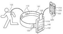
도 1을 참조하여 설명하면, 본 발명에 따른 인체 착용밴드(100)의 외형은 인체에 착용되는 착용수단(101), 착용수단(101)의 일측에 구비되는 수납수단(102)으로 구성된다. 착용수단(101)은 착용자의 착용 편의를 위해 신축성 있는 직물로 만들어진 밴드 형태로 구현된다. 착용수단(101)과 피부가 접촉하는 면에는 착용자의 생체신호를 측정하기 위한 하나 이상의 센서(111) 또는 전극을 포함하는 감지부(110)가 위치한다. 이때, 비접촉식 측정 방법을 사용하거나 3축 가속도 센서(111) 등을 이용하여 착용자의 움직임만을 측정하는 경우에는 상기 센서(111) 또는 전극들은 내장될 수 있다. 착용수단(101)의 일측에는 전자기기(200)를 수납할 수 있는 수납수단(102)이 구비된다. 수납수단(102)은 내부 공간에 전자기기(200)를 수납하는 수납공간부, 상기 수납된 전자기기(200)의 화면창(210)이 외부로 노출되도록 화면창(210)에 대응되는 영역에 형성되는 개구부(118)를 포함한다.Referring to Figure 1, the outer shape of the human wearing
그리고 수납수단(102)의 상부에는 내부에 삽입된 전자기기(200)가 외부로 빠져나오지 않도록 방지하는 고정수단(119)을 더 구비할 수 있다. 이때, 고정수단(119)은 수납수단(102) 뒷면에 부착될 수 있도록 벨크로나 단추 형태의 잠금수단을 이용하여 고정될 수 있으나, 수납수단(102)의 재질과 모양에 따라서는 별도의 잠금수단이 필요하지 않을 수도 있다. 수납수단(102)의 내부에는 착용수단(101)과 전자기기(200)의 광 데이터 송수신에 이용되는 광 확산부(143)가 위치한다. 광 확산부(143)는 그 구현 방법과 상기 수납수단(102)의 재질 및 모양에 따라 다양한 방법으로 구현될 수 있다. 예를 들면, 직물로 만든 수납수단(102) 내부의 일부 영역에 광섬유를 직조해 넣음으로써, 광 확산부(143)가 통합된 수납수단(102)을 구현할 수 있다. 또 다른 예로는 착용수단(101)의 기능을 수행하는 모든 회로를 직물 위에 직접 구현한 뒤에 이를 광 확산부가 내장된 별도의 외피에 넣어 일체된 착용수단(101)을 구현할 수 있다. 이때, 광 확산부(143)로 얇은 확산 필름을 이용하는 경우에는 수납수단(102)의 내부에 확산 필름을 접착시켜 수납수단(102)의 재질이 갖는 유연성을 유지시킬 수도 있다.In addition, the upper part of the
착용수단(101)은 전자기기(200)의 멀티미디어 재생 기능 제어를 위해 하나 이상의 직물형 버튼(120)을 구비하여 착용자의 터치 여부를 인식한다.The wearing means 101 includes one or
또한, 수납수단(102)에 수납되는 전자기기(200)의 외부 확장 포트에는 광신호 송수신을 위한 별도의 광 송신용 커넥터(220)가 연결된다. 이때, 전자기기(200)는 핸드폰, MP3, PMP, 등 다양한 엔터테인먼트 모바일 기기 중 어느 하나일 수 있다. 그리고 전자기기(200)에는 착용수단(101)으로부터의 데이터를 기록 또는 분석하기 위한 응용 소프트웨어(202)가 탑재된다. 이때, 응용 소프트웨어(202)는 별도의 GUI를 이용하여 착용자 관리, 착용수단(101)의 설정, 착용수단(101)에서 수신한 데이터의 기록과 분석 기능을 제공한다.In addition, a separate
한편, 도 2에 도시된 바와 같이, 본 발명에 따른 인체 착용밴드의 또 다른 외형은 앞서 설명한 밴드 형태가 아닌 띠 형태로 구성될 수 있다. 착용수단(101)을 구성하는 띠(103)의 일측에는 고리(104)가, 타측에는 벨크로 루프와 벨크로 후크(105, 106)가 구비되어. 벨크로 후크(106)가 위치한 타단을 고리(104)에 통과시켜 길이를 조정할 수 있도록 하여, 착용자의 팔 굵기에 맞도록 착용수단(101)의 지름을 자유롭게 조절할 수 있도록 한다.
On the other hand, as shown in Figure 2, another appearance of the wear band according to the present invention may be configured in the form of a band rather than the band described above. A
도 3은 본 발명의 인체 착용밴드에서의 직물형 인터페이스 장치에 대한 구성을 나타내는 구성도이고, 도 4는 본 발명의 인체 착용밴드에서의 직물형 인터페이스 장치에 대한 구성을 자세하게 나타내는 구성도이고, 도 5 내지 도 7은 본 발명의 인체 착용밴드에서의 직물 인터페이스 장치에 채용되는 직물형 버튼의 구조를 나타내는 구조도이고, 도 8은 본 발명의 인체 착용밴드에서의 직물 인터페이스 장치에 채용되는 광 송수신 커넥터의 구성을 나타내는 구성도이다.Figure 3 is a block diagram showing the configuration of the fabric type interface device in the wear band of the present invention, Figure 4 is a block diagram showing the configuration of the fabric type interface device in the wear band of the present invention in detail, Figure 5 to 7 are structural diagrams showing the structure of a fabric-type button employed in the fabric interface device of the human body wearing band of the present invention, and FIG. 8 is an optical transmission / reception connector of the fabric interface device of the human body wearing band of the present invention. It is a block diagram which shows a structure.
도 3 내지 도 4를 참조하여 설명하면, 본 발명에 따른 인체 착용밴드에서의 직물형 인터페이스 장치는 크게 감지부(110), 직물형 버튼(120), 마이크로 컨트롤러부(130), 광 수신부(141), 광 송신부(142), 광 확산부(143)를 포함하는 인터페이스부(140), 외부 인터페이스부(150), 외부 메모리(160)를 포함하여 구성된다.Referring to Figures 3 to 4, the textile interface device in the human body wearing band according to the present invention is largely the
감지부(110)는 인체에 착용 되는 착용수단(101)에 구비되어, 인체로부터 전달되는 생체신호를 검출한다. 이때, 감지부(110)는 착용수단(101)을 착용하는 착용자의 생체신호를 측정하기 위한 다수의 전극 또는 센서(111)를 구비할 수 있다. 일례로, 감지부(110)는 착용자의 운동량 측정을 위해 하나의 3차원 가속도 센서(111)만을 이용하여 물리적 움직임을 측정하되, 생체신호 정보를 추가로 감지하여 운동량계산에 활용할 수 있다. 그리고 감지부(110)는 심전도나 피부 저항은 전극으로, 혈류량이나 체온은 센서(111)를 이용하여 측정할 수 있다. 또한, 감지부(110)가 전극이 아닌 센서(111)를 이용하는 경우에는 착용수단(101)의 외부에 전극이 위치하지 않을 수 있다.The
감지부(110)는 물리적인 신호를 측정하는 전극 또는 센서(111)와 그 출력 신호를 처리하여 변환시키는 전처리부(112)를 포함한다, 이때, 전처리부(112)는 아날로그 신호를 디지털 신호 값으로 양자화하여 마이크로 컨트롤부로 전달한다. 보다 자세히 설명하면, 전처리부(112)는 전극 또는 센서(111)에 의해 검출된 생체신호에 대한 잡음 제거를 위한 필터(113), 생체신호를 증폭시키는 증폭기(114), 증폭된 생체신호를 디지털신호로 변환하는 변환기(115)를 포함하여, 마이크로 컨트롤부가 수신하고 처리할 수 있는 디지털 신호를 생성한다. 한편, 감지부(110)의 출력 신호가 이미 양자화된 디지털 신호 값인 경우에는 전처리부(112)가 생략될 수도 있다.
The
직물형 버튼(120)은 착용수단(101)에 다수개 구비되어, 수납수단(102)에 수납된 전자기기(200)를 제어하기 위한 제어신호를 발생시킨다. 착용자 인터페이스에 해당하는 직물형 버튼(120)은 도 5에 도시된 바와 같이 직물 위에 다음과 같이 구현될 수 있다.
직물형 버튼(120)은 전극과 전처리부로 구성된 일련의 회로가 마이크로 컨트롤러부(130)에 연결된 형태로 구성된다. 예를 들어 터치형 버튼(120)을 구성하고자 하는 경우, 착용자가 터치하게 되는 전극(121)과 해당 전극의 커패시턴스 변화를 인자하는 회로나 전용 컨트롤러를 이용하여 전처리부(122)의 회로를 구성한다. 즉, 전처리부(122)는 착용자가 전극(121)을 터치했을 때의 커패시턴스 변화를 인지하고 이를 마이크로 컨트롤러부(130)가 인식할 수 있도록 신호를 생성하여 전달한다. 한편, 직물형 버튼(120)이 최소 세 개의 터치형 버튼(120)으로 구비되고, 마이크로 컨트롤러부(130)가 더블 터치와 슬라이브 업 앤 다운 동작을 인식할 수 있도록 프로그램된 경우, 더블 터치 동작은 재생 또는 일시정지, 슬라이드 업 동작은 볼륨 업 그리고 슬라이드 다운 동작은 볼륨 다운 명령으로 대응할 수 있다.The
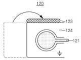
그리고 직물형 버튼(120)은 직물 상에 구현하기 위해서 직물(123), 직물(123) 상에 구비되는 버튼 형태의 전극(121), 전극(121) 주변을 감싸 전계를 제한하는 접지(124)로 구성된다. 이때, 직물형 버튼(120)은 손가락의 접근과 터치에 의한 커패시턴스 변화와 착용자의 팔의 접근에 의한 커패시턴스 변화가 전체 커패시턴스 변화에 영향을 주어 전체 터치 인식률을 떨어뜨리는 문제를 해결하기 위해, 도 5와 같이 전극(121)과 그 주변의 접지(124)를 직물 상에 구비하고, 접지의 일부 잉여영역을 절곡하여 전극(121)의 후면으로 돌려 접착시켜 전극(121)의 뒷면에 형성되는 전계를 제한한다. 여기서, 후면으로 돌려진 접지(124)의 잉여영역과 전극(121)의 간격에 변화가 생기면 전극(121)과 접지(124) 사이에 커패시턴스(Cg)가 변화하여 잘못된 인식을 할 수 있으므로 후면으로 돌려진 접지(124)의 잉여영역과 직물이 완전히 접착되도록 한다. 도 5와 같은 형태의 전극과 접지를 직물 위해 구비한 뒤 착용수단(101)의 외부 내부에 삽입되어 착용자의 팔에 착용되면 그 단면은 도 6과 같으며 전극(121)의 아래 방향으로 형성되는 전계가 전극(121) 바로 아래 위치하는 후면으로 돌려진 접지(124)에 의해 차단되어 버튼(120) 터치 효과를 향상시킬 수 있다. 한편, 경우에 따라서는 도 7과 같이 임의의 두께를 가지는 별도의 접착제(125)를 사용하여 전극(121)과 후면으로 돌려진 접지(124)의 간격을 고정시킴과 동시에 접착제(125)의 두께를 조정하여 전극(121)에 형성되는 기본 커패시턴스 값을 조정할 수도 있다.
And the
마이크로 컨트롤러부(130)는 감지부(110)와 인터페이스부(140) 사이에 구비되며, 감지부(110) 또는 직물형 버튼(120)으로부터 제공되는 신호에 대한 후처리를 수행하고, 그 결과를 인터페이스부(140)를 통해 전자기기(200)로 전송되도록 제어한다. 마이크로 컨트롤러부(130)는 후처리 성능과 전원 요구사항, 그리고 착용수단(101)의 기능적인 요구사항에 따라 소프트웨어 변경을 통해 새로운 설정을 적용할 수 있다. 그 예로, 마이크로 컨트롤러부(130)는 감지부(110)로부터 제공되는 신호를 바로 인터페이스부(140)를 통해 전자기기(200)로 전송하여 모든 운동량 계산 알고리즘이 전자기기(200)에서 수행되도록 하거나, 감지부(110)로부터 제공되는 신호를 분석하여 의미 있는 중간정보로 도출한 뒤에, 해당 정보를 인터페이스부(140)를 통해 전자기기(200)로 전송할 수 있다. 또한, 마이크로 컨트롤러부(130)는 감지부(110)로부터 제공되는 신호를 모두 분석한 뒤 전자기기(200)의 화면창(210)에 표시될 정보만을 인터페이스부(140)를 통해 전송할 수 있다. 또한, 마이크로 컨트롤러부(130)는 별도의 외부 메모리(160)를 구비하여, 감지부(110)로부터 제공되는 값 또는 분석을 통해 도출된 의미 있는 중간정보를 인터페이스부(140)를 통해 전자기기(200)로 전송함과 동시에 외부 메모리(160)에 저장할 수 있다. 그러나 마이크로 컨트롤러가 충분한 메모리 공간을 가지고 있는 경우에는 별도의 외부 메모리(160)를 구비하지 않을 수 있다.
The
인터페이스부(140)는 착용수단(101)의 일측에 구비되는 수납수단(102)의 내부에 형성되어, 수납수단(102)에 수납되는 전자기기(200)와의 통신을 수행한다.The
이를 위해 인터페이스부(140)는 광 수신부(141), 광 송신부(142), 광 확산부(143)를 포함한다.To this end, the
광 수신부(141)는 광 신호를 수신하기 위해, 포토 다이오드 및 적외선 센서 중 어느 하나를 포함하는 증폭회로로 형성된다.The
광 송신부(142)는 광 신호를 송신하기 위해, 적외선 LED 및 레이저 중 어느 하나를 포함하는 구동회로로 형성된다. 이때, 광 송신부(142)는 수납수단(102)에 수납되는 전자기기(200)의 광 송수신용 커넥터(220)만이 광 신호를 검출할 수 있도록 최소한의 세기로 광 신호를 전송한다.The
광 수신부(141) 및 광 송신부(142)는 하나의 광 확산부(143)에 연결된다. 광 확산부(143)는 광 시호 송신시 광을 확산시키기 위해 발광형 플라스틱 광섬유 및 EL 와이어 중 어느 하나를 포함하여 면 형태로 직물 상에 넓게 분포되도록 하여 전자기기(200)가 더욱 효과적으로 광 신호를 수신할 수 있도록 한다. 이때, 광 수신부(141) 및 광 송신부(142)는 하나의 광 확산부(143)를 공유하므로 송신과 수신을 동시에 할 수 없다. 따라서, 광 수신부(141)와 광 송신부(142)의 광 신호 송신과 수신 시점은 마이크로 컨트롤러부(130)에 의해 제어되며 매체 공유를 위해 TDM, CSMA/CD나 CSMA/CA와 같은 다양한 방식들 중 하나를 이용할 수 있다.The
착용수단(101)은 추가로 외부 인터페이스부(150) 및 전원부(151)를 포함한다. 외부 인터페이스부(150)는 USB와 같은 외부 연결을 제공함으로써, 마이크로 컨트롤러부(130)의 디버깅, 소프트웨어 프로그래밍, 외부 메모리(160)의 데이터 전송을 수행할 수 있으며, USB 전원을 전원부(151)로 전달함으로써, 착용수단(101)의 내장 배터리 충전에도 활용할 수 있다.
The wearing means 101 further includes an
광 송수신 커넥터(220)는 전자기기(200)와 인터페이스부(140)와의 광 통신을 위해, 전자기기(200)의 외부 확장 포트(201)에 연결된다. 도 8에 도시된 바와 같이, 광 송수신 커넥터(220)는 전자기기(200)의 외부 확장 포트(201)에 접속되는 연결 포트(221), 전자기기(200)로부터의 신호를 광 신호 형태로 송신하는 송신부(224), 인터페이스부(140)로부터의 광 신호를 수신하는 수신부(223), 전자기기(200)와 인터페이스부(140)간에 송수신되는 신호를 전달하고 제어하는 제어부(222)를 포함한다.The optical transmission /
광 송수신 커넥터(220)의 전원은 전자기기(200)로부터 공급되는 전원을 이용하거나 만약 공급되지 않는 경우 자체 전원을 이용하여 동작한다. 광 송수신 커넥터(220)의 통신은 전자기기(200)의 고유의 프로토콜을 이용하거나 UART, USB와 같은 임의의 표준 직렬 통신 프로토콜을 이용할 수 있다.The power of the optical transmission /
광 송수신 커넥터(220)의 수신부(223)와 송신부(224)는 착용수단(101)의 광 수신부(141)와 광 송신부(142)와 동일한 방식으로 광 신호를 송수신한다. 이처럼, 광 송수신 커넥터(220)의 수신부(223)와 송신부(224)는 착용수단(101)의 광 수신부(141)와 광 송신부(142)와 동일한 형태로 구현될 수 있으나, 공통의 광 확산부를 이용하지는 않는다.The
광 송수신 커넥터(220)의 제어부(222)는 전자기기(200)로부터의 데이터를 송신부(224)를 통해 송신하고, 수신부(223)를 통해 수신한 데이터를 전자기기(200)로 전달한다.The
이와 같이 구성된 광 송수신 커넥터(220)와 전자기기(200)의 상호 연결상태를 자세히 설명하기 위해, 마스터와 슬레이브간의 연결상태로 설명한다.In order to describe in detail the interconnection state of the optical transmission and
예를 들면, 착용수단(101)이 마스터이고, 전자기기(200)가 슬레이브로 구현된다. 이는 반대로의 구현도 가능하나, 하기에는 상기에 언급된 구성으로 구현되는 것을 기본으로 한다. 마스터와 슬레이브가 각각 동작을 시작하면, 마스터는 응답 메시지를 대기하며, 마스터는 그 응답 메시지의 수신 여부에 관계없이 주기적으로 발견 메시지를 송신한다. 이때, 발견 메시지는 최소한 메시지 구분을 위한 타입 정보와 다음 전송될 발견 메시지까지의 시간을 포함하며, 추가로 마스터 장치의 제품 정보와 소프트웨어 버전 정보 등을 추가로 포함할 수 있다. 또한 메시지 주기는 연결 설정 이전과 이후, 전송오류, 연결 지속시간 등을 고려하여 마스터가 동적으로 변경할 수 있다. 마스터가 자신이 전송한 발견 메시지에 대한 발견 응답 메시지를 슬레이브로부터 수신하면 슬레이브와의 연결이 설정되었다고 판단하며, 그렇지 못한 경우에는 연결이 해제되었다고 판단한다. 마스터는 주기적인 발견 응답 메시지의 연속수신 횟수를 이용하여 연결과 해제를 판단할 수 있다. 추가로, 마스터는 외부 소프트웨어나 착용자 인터페이스를 통한 착용자의 의도를 직접 반영하여 연결을 강제로 해제할 수도 있다. 슬레이브가 발견 메시지를 수신하면 발견 응답 메시지를 생성해 마스터로 전송하고 마스터와 연결이 되었다고 판단한다. 이때, 수신한 발견 메시지에 포함된 다음 발견 메시지까지의 시간까지 적어도 하나 이상의 발견 메시지가 추가로 수신되는 경우에 한해 그 연결 상태가 유지되며, 어느 일정 시간까지 추가 발견 메시지가 수신되지 않으면 마스터와 연결이 해제된다. 발견 응답 메시지는 최소한 메시지 구분을 위한 타입 정보를 포함하며, 추가로 슬레이브 장치의 제품 정보와 소프트웨어 버전 정보 등을 추가로 포함할 수 있다. 슬레이브는 주기적인 발견 메시지의 연속 수신 횟수를 이용하여 연결과 해제를 판단할 수 있다.
For example, the wearing means 101 is a master, and the
이하, 본 발명의 실시예에 따른 인체 착용밴드에서의 직물형 인터페이스 방법을 첨부된 도면을 참조하여 상세하게 설명하면 아래와 같다.
Hereinafter, with reference to the accompanying drawings, the fabric type interface method in a wear band according to an embodiment of the present invention will be described in detail.
도 9는 본 발명의 인체 착용밴드에서의 직물 인터페이스 방법에 대한 흐름을 나타내는 흐름도이고, 도 10은 본 발명의 인체 착용밴드에서의 직물 인터페이스 방법에서 광 통신이 수행되는 방법을 나타내는 흐름도이다.FIG. 9 is a flowchart illustrating a flow of the fabric interface method in the wear band of the present invention, and FIG. 10 is a flowchart illustrating a method of performing optical communication in the fabric interface method in the wear band of the present invention.
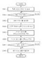
도 9 및 도 10에 도시된 바와 같이, 본 발명은 먼저, 인체에 착용되는 착용수단(101)에 구비된 감지부(110)를 통해 착용자의 생체신호를 검출한다.(S100) 이때, 감지부(110)는 착용수단(101)을 착용하는 생체신호를 측정하기 위한 다수의 전극 또는 센서(111)를 구비할 수 있다.9 and 10, the present invention first detects a wearer's biosignal through a
다음으로, 착용수단(101)이 구비한 마이크로 컨트롤부는 생체신호와 버튼입력정보를 수신한다.(S200) 이때, 생체신호는, 감지부의(110)의 전처리부(112)에 의해서, 필터링, 증폭, 디지털 변환되어 제공될 수 있다.Next, the micro-control unit provided with the wearing means 101 receives the biosignal and the button input information (S200). At this time, the biosignal is filtered and amplified by the
다음으로, 인터페이스부(140)를 통해 수납수단(102)에 수납되는 전자기기(200)와 상호 광 통신을 수행한다.(S300)Next, the
보다 자세하게 설명하면, 응용 소프트웨어(202)가 실행중인 전자기기(200)를 전원이 켜진 착용수단(101)의 수납수단(102)에 수납하면, 착용수단(101)과 전자기기(200)가 연결된다.(S301) 착용수단(101)이 연결되었음을 인지(S301)하면, 착용수단(101)은 자동으로 감지부(110)와 그 신호들의 검출 기능을 활성화(S303)시키고 검출된 신호를 전자기기(200)에 전송한다.(S304) 이때, 전송되는 신호는 그 검출 주기에 맞춰 주기적으로 전송되거나 일정한 양을 모아 한꺼번에 전송될 수 있다. 착용수단(101)의 인터페이스부(140)를 통해 전송되는 광 신호는 전자기기(200)의 외부 확장 포트에 연결되는 광 송수신용 커넥터(220)를 통해 전자기기(200)의 응용 소프트웨어(202)로 전달(S305)된다. 이때, 광 송수신용 커넥터(220)에 구비되는 제어부(222)가 수신한 광 신호 형식을 전자기기(200)와 응용 소프트웨어(202)가 인식할 수 있는 신호 형식으로 변환하는 작업을 추가로 수행할 수도 있다. 그리고 응용 소프트웨어(202)는 수신한 신호를 착용자가 인지할 수 있는 형식으로 변환해 표시하며, 필요에 따라 전자기기(200)가 기본으로 제공하는 기본기능(시간, 위치, 고도 등)을 활용하여 데이터에 대해 기록, 분석, 가공을 추가로 수행(S306)할 수 있다. 이후 연결된 상태라면, 착용수단(101)에서 검출된 정보를 전자기기(200)에서 실시간으로 표시하는 과정을 반복한다. 그러나 만약 수납수단(102)에서 전자기기(200)를 분리시키거나 어느 하나의 전원이 꺼지거나, 응용 소프트웨어(202)를 중단하여 상호 연결이 해제(S307)되면, 착용수단(101)은 자동으로 감지부(110)와 그 신호들의 처리 기능을 비활성화(S308)시켜 전력 소모를 최소화시킬 수 있다.
In more detail, when the
이처럼, 본 발명은 인체 착용밴드의 광 통신을 위한 주요 회로, 착용자 인터페이스를 직물기반으로 구성함으로써, 제 3의 장치들과의 주파수 간섭 및 보안 문제를 회피하여 통신성능을 향상시킬 수 있다.
As such, the present invention can improve communication performance by avoiding frequency interference and security problems with third-party devices by constructing a fabric-based main circuit and wearer interface for optical communication of a human body wearing band.
이상에서 본 발명에 따른 바람직한 실시예에 대해 설명하였으나, 다양한 형태로 변형이 가능하며, 본 기술분야에서 통상의 지식을 가진자라면 본 발명의 특허청구범위를 벗어남이 없이 다양한 변형예 및 수정예를 실시할 수 있을 것으로 이해된다.While the present invention has been described in connection with what is presently considered to be practical exemplary embodiments, it is to be understood that the invention is not limited to the disclosed embodiments, but many variations and modifications may be made without departing from the scope of the present invention. It will be understood that the invention may be practiced.
100 : 인체 착용밴드 101 : 착용수단
102 : 수납수단 110 : 감지부
120 : 직물형 버튼 130 : 마이크로 컨트롤러부
140 : 인터페이스부 150 : 외부 인터페이스부
200 : 전자기기
100: wear body band 101: wearing means
102: storage means 110: detection unit
120: fabric button 130: microcontroller
140: interface unit 150: external interface unit
200: Electronic device
Claims (14)
Translated fromKorean상기 착용수단의 일측에 구비되는 수납수단의 내부에 형성되어, 상기 수납수단에 수납되는 전자기기와의 통신을 수행하는 인터페이스부; 및
상기 전자기기를 제어하기 위한 제어신호를 발생시키는 다수개의 직물형 버튼;을 포함하며,
상기 인터페이스부는 광 신호를 수신하는 광 수신부; 상기 광 신호를 송신하는 광 송신부; 및 상기 광 신호 송신시 광을 확산시키는 광 확산부를 직물에 구비하여 상기 전자기기와 광을 매개로 통신하며,
상기 직물형 버튼은 직물; 상기 직물 상에 구비되는 버튼 형태의 전극; 및 상기 전극을 감싸는 접지;를 포함하되, 상기 접지는 일단의 잉여영역을 절곡하여, 상기 잉여영역이 상기 전극의 후면에 위치하도록 하는 것을 특징으로 하는 인체 착용밴드에서의 직물형 인터페이스 장치.It is provided in the wearing means worn on the human body, the detection unit for detecting a biological signal from the human body;
An interface unit which is formed in an accommodation unit provided at one side of the wearing unit and communicates with an electronic device accommodated in the accommodation unit; And
Includes; a plurality of textile buttons for generating a control signal for controlling the electronic device,
The interface unit includes an optical receiver for receiving an optical signal; An optical transmitter for transmitting the optical signal; And a light diffusing part for diffusing light when transmitting the optical signal to the fabric to communicate with the electronic device through light.
The textile button is a fabric; An electrode in the form of a button provided on the fabric; And a ground surrounding the electrode, wherein the ground is bent at one end of the surplus region so that the surplus region is located at the rear of the electrode.
상기 감지부는,
상기 착용수단을 착용하는 착용자의 생체신호를 측정하기 위한 다수개의 전극 또는 센서를 구비하는 것을 특징으로 하는 인체 착용밴드에서의 직물형 인터페이스 장치.The method of claim 1,
The sensing unit includes:
Fabric type interface device in the human body wearing band comprising a plurality of electrodes or sensors for measuring the bio-signal of the wearer wearing the wearing means.
상기 감지부는,
상기 전극 또는 센서로 검출한 생체신호를 디지털화하는 전처리부를 더 포함하는 것을 특징으로 하는 인체 착용밴드에서의 직물형 인터페이스 장치.The method of claim 2,
The sensing unit includes:
The prefabricated interface device of the human body wearing band, characterized in that it further comprises a pre-processing unit for digitizing the biological signal detected by the electrode or sensor.
상기 전처리부는,
상기 검출된 생체신호에 대한 잡음을 제거하는 필터;
상기 잡음이 제거된 생체신호를 증폭하는 증폭기; 및
상기 증폭된 생체신호를 디지털화하는 변환기;
를 포함하는 것을 특징으로 하는 인체 착용밴드에서의 직물형 인터페이스 장치.The method of claim 3, wherein
The pre-
A filter for removing noise on the detected biosignal;
An amplifier for amplifying the noise-free biological signal; And
A converter for digitizing the amplified biosignal;
Fabric type interface device in the human body wearing band comprising a.
상기 광 수신부는,
포토 다이오드 및 적외선 센서 중 어느 하나를 포함하는 증폭회로로 형성되는 것을 특징으로 하는 인체 착용밴드에서의 직물형 인터페이스 장치.The method of claim 1,
The light receiving unit,
Fabric type interface device in the human body wearing band, characterized in that formed by an amplifier circuit including any one of a photodiode and an infrared sensor.
상기 광 확산부는,
발광형 플라스틱 광섬유 및 EL 와이어 중 어느 하나를 포함하여 면 형태로 형성되는 것을 특징으로 하는 인체 착용밴드에서의 직물형 인터페이스 장치.The method of claim 1,
The light diffusion unit,
Fabric type interface device in a human body wearing band, characterized in that formed in the form of a surface including any one of a light emitting plastic optical fiber and an EL wire.
상기 감지부와 상기 인터페이스부 사이에는 마이크로 컨트롤러부가 구비되며, 상기 마이크로 컨트롤러부는 외부로부터 제공되는 신호에 대한 후처리를 수행하고, 상기 인터페이스를 통해 상기 전자기기와의 데이터 송수신을 제어하는 것을 특징으로 하는 인체 착용밴드에서의 직물형 인터페이스 장치.The method of claim 1,
A microcontroller is provided between the sensing unit and the interface unit, and the microcontroller performs post-processing on signals provided from the outside and controls data transmission and reception with the electronic device through the interface. Woven interface device in the wear band.
상기 전자기기는 상기 인터페이스부로부터 수신되는 상기 광 신호에 대한 데이터를 기록하고 분석하는 응용 소프트웨어를 포함하는 것을 특징으로 하는 인체 착용밴드에서의 직물형 인터페이스 장치.The method of claim 1,
And the electronic device includes application software for recording and analyzing data on the optical signal received from the interface unit.
상기 전자기기는 상기 인터페이스부와의 광 통신을 수행하기 위해, 상기 전자기기의 외부 확장 포트에 연결되는 광 송수신 커넥터를 구비하며,
상기 광 송수신 커넥터는,
상기 전자기기의 외부 확장 포트에 접속되는 연결 포트;
상기 전자기기로부터의 광 신호를 송신하는 송신부;
상기 인터페이스부로부터의 광 신호를 수신하는 수신부; 및
상기 전자기기와 상기 인터페이스부간에 송수신되는 광 신호의 변환과 상기 광 신호의 변환을 위한 버퍼링을 수행하는 제어부;를 포함하는 것을 특징으로 하는 인체 착용밴드에서의 직물형 인터페이스 장치.The method of claim 1,
The electronic device includes an optical transmission / reception connector connected to an external expansion port of the electronic device to perform optical communication with the interface unit.
The optical transmission and reception connector,
A connection port connected to an external expansion port of the electronic device;
A transmitter for transmitting an optical signal from the electronic device;
A receiver which receives an optical signal from the interface unit; And
And a control unit for converting an optical signal transmitted and received between the electronic device and the interface unit and buffering the optical signal.
상기 착용수단은 외부 디비거와의 연결 및 충전을 수행하는 외부 인터페이스부를 더 포함하는 것을 특징으로 하는 인체 착용밴드에서의 직물형 인터페이스 장치.The method of claim 1,
The wearing means further comprises an external interface unit for performing connection and charging with the external debugger, the fabric type interface device in the human body wearing band.
상기 수납수단은,
내부 공간에 상기 전자기기를 수납하는 수납공간부; 및
상기 수납된 전자기기의 화면창이 외부로 노출되도록, 상기 화면창에 대응되는 영역에 형성되는 개구부;를 포함하는 것을 특징으로 하는 인체 착용밴드에서의 직물형 인터페이스 장치.The method of claim 1,
The storage means,
An accommodation space unit accommodating the electronic device in an internal space; And
And an opening formed in an area corresponding to the screen window so that the screen window of the stored electronic device is exposed to the outside.
상기 착용수단의 일측에 구비되는 수납수단의 내부에 직물형태로 형성되는 인터페이스부에 의해, 상기 생체신호와 직물형 버튼으로부터 발생되는 제어신호를 수신하는 단계; 및
상기 인터페이스부에 의해, 상기 수납수단에 수납되는 전자기기와의 광 통신을 수행하는 단계;를 포함하되,
상기 광 통신을 수행하는 단계에서는,
상기 수납공간에 상기 전자기기가 삽입되면, 상기 인터페이스부를 통해 광 통신을 위한 연결을 완료하는 단계;
상기 인터페이스부를 통해 상기 생체신호와 직물형 버튼으로부터 발생되는 제어신호를 상기 전자기기에 송신하는 단계;
상기 전자기기의 응용 소프트웨어에 의해, 상기 생체신호에 대한 데이터를 기록하고 분석하는 단계; 및
상기 전자기기의 응용 소프트웨어에 의해, 상기 직물형 버튼으로부터 발생되는 제어신호를 기반으로 상기 전자기기를 제어하는 단계;
를 포함하는 것을 특징으로 하는 인체 착용밴드에서의 직물형 인터페이스 방법.Detecting a wearer's biosignal by a detector provided in the wearing unit;
Receiving a control signal generated from the bio-signal and the fabric button by the interface unit formed in the fabric form inside the receiving means provided on one side of the wearing means; And
By the interface unit, performing optical communication with the electronic device accommodated in the receiving means;
In the step of performing the optical communication,
When the electronic device is inserted into the storage space, completing the connection for optical communication through the interface unit;
Transmitting a control signal generated from the bio-signal and the textile button to the electronic device through the interface unit;
Recording and analyzing data on the biosignal by application software of the electronic device; And
Controlling, by the application software of the electronic device, the electronic device based on a control signal generated from the textile button;
Fabric type interface method in a human wearing band comprising a.
상기 생체신호와 직물형 버튼으로부터 발생되는 제어신호를 수신하는 단계에서는,
상기 감지부의 전처리부에 의해서, 상기 생체신호의 잡음을 제거하고 증폭한 뒤 디지털화 하는 단계;를 더 포함하는 것을 특징으로 하는 인체 착용밴드에서의 직물형 인터페이스 방법.13. The method of claim 12,
In the step of receiving the biological signal and the control signal generated from the fabric button,
The pre-processing unit of the sensor, removing the noise of the biological signal, amplifying and digitizing; fabric type interface method in a human body wearing band further comprising.
상기 상호 광 통신을 수행하는 단계에서,
상기 전자기기는 외부 확장 포트에 연결되는 광 송수신 커넥터에 의해, 상기 인터페이스부와 광 통신을 수행하는 것을 특징으로 하는 인체 착용밴드에서의 직물형 인터페이스 방법.
13. The method of claim 12,
In the step of performing the mutual optical communication,
The electronic device is a textile interface method in a human body wearing band characterized in that for performing optical communication with the interface unit by an optical transmission and reception connector connected to an external expansion port.
Priority Applications (2)
| Application Number | Priority Date | Filing Date | Title |
|---|---|---|---|
| KR1020120022521AKR20130126760A (en) | 2012-03-05 | 2012-03-05 | Apparatus and method for textile-type interface in human wearing band |
| US13/776,957US20130229338A1 (en) | 2012-03-05 | 2013-02-26 | Textile interface device and method for use with human body-worn band |
Applications Claiming Priority (1)
| Application Number | Priority Date | Filing Date | Title |
|---|---|---|---|
| KR1020120022521AKR20130126760A (en) | 2012-03-05 | 2012-03-05 | Apparatus and method for textile-type interface in human wearing band |
Publications (1)
| Publication Number | Publication Date |
|---|---|
| KR20130126760Atrue KR20130126760A (en) | 2013-11-21 |
Family
ID=49042546
Family Applications (1)
| Application Number | Title | Priority Date | Filing Date |
|---|---|---|---|
| KR1020120022521AWithdrawnKR20130126760A (en) | 2012-03-05 | 2012-03-05 | Apparatus and method for textile-type interface in human wearing band |
Country Status (2)
| Country | Link |
|---|---|
| US (1) | US20130229338A1 (en) |
| KR (1) | KR20130126760A (en) |
Cited By (4)
| Publication number | Priority date | Publication date | Assignee | Title |
|---|---|---|---|---|
| KR20160105999A (en)* | 2015-03-01 | 2016-09-09 | 삼성전자주식회사 | Apparatus and method for controlling power |
| KR101984014B1 (en)* | 2018-02-06 | 2019-05-31 | 김주현 | Portable arm-band capable of 3 direction light emitting |
| US12013725B2 (en) | 2013-11-29 | 2024-06-18 | Ouraring, Inc. | Wearable computing device |
| US12443230B2 (en) | 2025-02-28 | 2025-10-14 | Ouraring Inc. | Wearable computing device |
Families Citing this family (9)
| Publication number | Priority date | Publication date | Assignee | Title |
|---|---|---|---|---|
| US9588582B2 (en) | 2013-09-17 | 2017-03-07 | Medibotics Llc | Motion recognition clothing (TM) with two different sets of tubes spanning a body joint |
| US9582072B2 (en) | 2013-09-17 | 2017-02-28 | Medibotics Llc | Motion recognition clothing [TM] with flexible electromagnetic, light, or sonic energy pathways |
| CN105264467B (en)* | 2013-06-07 | 2018-10-12 | 精工爱普生株式会社 | Electronic equipment and clicking operation detection method |
| FR3038919B1 (en)* | 2015-07-13 | 2018-11-09 | Ets A. Deschamps Et Fils | METHOD AND MACHINE FOR MANUFACTURING A WOVEN STRUCTURE |
| US10831922B1 (en)* | 2015-10-30 | 2020-11-10 | United Services Automobile Association (Usaa) | System and method for access control |
| KR20170138667A (en)* | 2016-06-08 | 2017-12-18 | 삼성전자주식회사 | Method for activating application and electronic device supporting the same |
| US11292236B1 (en)* | 2017-03-17 | 2022-04-05 | Apple Inc. | Fabric items with locally thinned fabric |
| US11952087B2 (en) | 2020-12-11 | 2024-04-09 | Alessandra E. Myslinski | Smart apparel and backpack system |
| US20230275820A1 (en)* | 2022-02-28 | 2023-08-31 | Juniper Networks, Inc. | Successful connects metrics for monitoring and control of wireless or wired networks |
Family Cites Families (13)
| Publication number | Priority date | Publication date | Assignee | Title |
|---|---|---|---|---|
| US6473483B2 (en)* | 1998-10-28 | 2002-10-29 | Nathan Pyles | Pedometer |
| US6593755B1 (en)* | 2000-07-31 | 2003-07-15 | Banner Engineering Corporation | Method and apparatus for detection sensor shielding |
| JP4181901B2 (en)* | 2002-05-10 | 2008-11-19 | アルプス電気株式会社 | Input device and electronic device |
| KR100634494B1 (en)* | 2002-08-19 | 2006-10-16 | 삼성전기주식회사 | Wearable information input device, information processing device and information input method |
| US7627343B2 (en)* | 2003-04-25 | 2009-12-01 | Apple Inc. | Media player system |
| US7777501B2 (en)* | 2005-06-03 | 2010-08-17 | Synaptics Incorporated | Methods and systems for sigma delta capacitance measuring using shared component |
| US8740751B2 (en)* | 2005-07-25 | 2014-06-03 | Nike, Inc. | Interfaces and systems for displaying athletic performance information on electronic devices |
| DE102005041112A1 (en)* | 2005-08-30 | 2007-03-01 | BSH Bosch und Siemens Hausgeräte GmbH | Capacitive proximity switch for e.g. washing machine, has sensor surface with active shielding formed by shielding surface, and clock signal applied at shielding surface that is connected with earth for applying potential by switch |
| US8188868B2 (en)* | 2006-04-20 | 2012-05-29 | Nike, Inc. | Systems for activating and/or authenticating electronic devices for operation with apparel |
| JP4988016B2 (en)* | 2009-08-27 | 2012-08-01 | 韓國電子通信研究院 | Finger motion detection apparatus and method |
| KR101249736B1 (en)* | 2009-09-07 | 2013-04-03 | 한국전자통신연구원 | Textile-based magnetic field interface clothes and mobile terminal in wearable computing system |
| US20110172498A1 (en)* | 2009-09-14 | 2011-07-14 | Olsen Gregory A | Spot check monitor credit system |
| US20110224499A1 (en)* | 2010-03-10 | 2011-09-15 | Sotera Wireless, Inc. | Body-worn vital sign monitor |
- 2012
- 2012-03-05KRKR1020120022521Apatent/KR20130126760A/ennot_activeWithdrawn
- 2013
- 2013-02-26USUS13/776,957patent/US20130229338A1/ennot_activeAbandoned
Cited By (26)
| Publication number | Priority date | Publication date | Assignee | Title |
|---|---|---|---|---|
| US12393228B2 (en) | 2013-11-29 | 2025-08-19 | Ouraring Inc. | Wearable computing device |
| US12429908B2 (en) | 2013-11-29 | 2025-09-30 | Ouraring Inc. | Wearable computing device |
| US12013725B2 (en) | 2013-11-29 | 2024-06-18 | Ouraring, Inc. | Wearable computing device |
| US12210381B2 (en) | 2013-11-29 | 2025-01-28 | Ouraring, Inc. | Wearable computing device |
| US12222759B2 (en) | 2013-11-29 | 2025-02-11 | Ouraring, Inc. | Wearable computing device |
| US12222758B2 (en) | 2013-11-29 | 2025-02-11 | Ouraring, Inc. | Wearable computing device |
| US12228968B2 (en) | 2013-11-29 | 2025-02-18 | Ouraring, Inc. | Wearable computing device |
| US12235679B2 (en) | 2013-11-29 | 2025-02-25 | Ouraring, Inc. | Wearable computing device |
| US12332688B2 (en) | 2013-11-29 | 2025-06-17 | Ouraring, Inc. | Wearable computing device |
| US12332689B1 (en) | 2013-11-29 | 2025-06-17 | Ouraring Inc. | Wearable computing device |
| US12346160B2 (en) | 2013-11-29 | 2025-07-01 | Ouraring, Inc. | Wearable computing device |
| US12393229B2 (en) | 2013-11-29 | 2025-08-19 | Ouraring Inc. | Wearable computing device |
| US12393227B2 (en) | 2013-11-29 | 2025-08-19 | Ouraring, Inc. | Wearable computing device |
| US12436566B2 (en) | 2013-11-29 | 2025-10-07 | Ouraring Inc. | Wearable computing device |
| US12429911B2 (en) | 2013-11-29 | 2025-09-30 | Ouraring Inc. | Wearable computing device |
| US12399530B2 (en) | 2013-11-29 | 2025-08-26 | Ouraring Inc. | Wearable computing device |
| US12422889B2 (en) | 2013-11-29 | 2025-09-23 | Ouraring Inc. | Wearable computing device |
| US12429910B2 (en) | 2013-11-29 | 2025-09-30 | Ouraring Inc. | Wearable computing device |
| US12399531B2 (en) | 2013-11-29 | 2025-08-26 | Ouraring Inc. | Wearable computing device |
| US12429909B2 (en) | 2013-11-29 | 2025-09-30 | Ouraring Inc. | Wearable computing device |
| KR20160105999A (en)* | 2015-03-01 | 2016-09-09 | 삼성전자주식회사 | Apparatus and method for controlling power |
| KR101984014B1 (en)* | 2018-02-06 | 2019-05-31 | 김주현 | Portable arm-band capable of 3 direction light emitting |
| US12443229B2 (en) | 2025-02-26 | 2025-10-14 | Ouraring Inc. | Wearable computing device |
| US12443228B2 (en) | 2025-02-26 | 2025-10-14 | Ouraring Inc. | Wearable computing device |
| US12443230B2 (en) | 2025-02-28 | 2025-10-14 | Ouraring Inc. | Wearable computing device |
| US12443231B2 (en) | 2025-03-07 | 2025-10-14 | Ouraring Inc. | Wearable computing device |
Also Published As
| Publication number | Publication date |
|---|---|
| US20130229338A1 (en) | 2013-09-05 |
Similar Documents
| Publication | Publication Date | Title |
|---|---|---|
| KR20130126760A (en) | Apparatus and method for textile-type interface in human wearing band | |
| KR102313220B1 (en) | Wearable device and method for controlling thereof | |
| US9044150B2 (en) | Biometric monitoring device with heart rate measurement activated by a single user-gesture | |
| US9042971B2 (en) | Biometric monitoring device with heart rate measurement activated by a single user-gesture | |
| US10559220B2 (en) | Systems and methods for creating a neural network to provide personalized recommendations using activity monitoring devices with biometric sensors | |
| US9872619B2 (en) | Physiological sensor pod with reset circuit | |
| US20250104855A1 (en) | Wearable sensor and system thereof | |
| US20080208009A1 (en) | Wearable Device, System and Method for Measuring Vital Parameters | |
| CN103263257B (en) | Remote vital sign measuring system | |
| CN106456008A (en) | Methods and systems for cardiac monitoring using mobile devices and accessories | |
| CN113365550B (en) | Method and electronic device for calculating recovery index based on REM sleep stage | |
| KR20160105396A (en) | Battery charger related applications | |
| KR102533993B1 (en) | Electronic device generating health information based on a plurality of biometric signal and method of operating the same | |
| CN206274673U (en) | heart rate monitor earphones | |
| US20230073907A1 (en) | Configurable wake up alarm using physiological monitoring | |
| CN203369894U (en) | Remote vital sign measuring device and system | |
| US20230284980A1 (en) | Detecting position of a wearable monitor | |
| CN205388810U (en) | Human vital sign and gesture detection pants | |
| KR101203902B1 (en) | Bio-signal measurement unit of exercise prescription system | |
| CN204839486U (en) | A physiological monitoring system applied to intelligent devices | |
| CN211270775U (en) | Ear clip type blood oxygen detector | |
| CN210990274U (en) | Wearable electronic device | |
| CN202891941U (en) | Oximeter step measuring instrument and data processing system | |
| TWI612940B (en) | Combination physiological signal measuring device | |
| CN204950920U (en) | Miniature vital sign detecting device |
Legal Events
| Date | Code | Title | Description |
|---|---|---|---|
| PA0109 | Patent application | Patent event code:PA01091R01D Comment text:Patent Application Patent event date:20120305 | |
| PG1501 | Laying open of application | ||
| PC1203 | Withdrawal of no request for examination | ||
| WITN | Application deemed withdrawn, e.g. because no request for examination was filed or no examination fee was paid |