KR20130122629A - System and method using proximity detection for reducing cart alarms and increasing sensitivity in an eas system with metal shielding detection - Google Patents
System and method using proximity detection for reducing cart alarms and increasing sensitivity in an eas system with metal shielding detectionDownload PDFInfo
- Publication number
- KR20130122629A KR20130122629AKR1020137011072AKR20137011072AKR20130122629AKR 20130122629 AKR20130122629 AKR 20130122629AKR 1020137011072 AKR1020137011072 AKR 1020137011072AKR 20137011072 AKR20137011072 AKR 20137011072AKR 20130122629 AKR20130122629 AKR 20130122629A
- Authority
- KR
- South Korea
- Prior art keywords
- eas
- detector
- infrared
- metal
- subsystem
- Prior art date
- Legal status (The legal status is an assumption and is not a legal conclusion. Google has not performed a legal analysis and makes no representation as to the accuracy of the status listed.)
- Granted
Links
Images


Classifications
- G—PHYSICS
- G08—SIGNALLING
- G08B—SIGNALLING OR CALLING SYSTEMS; ORDER TELEGRAPHS; ALARM SYSTEMS
- G08B13/00—Burglar, theft or intruder alarms
- G08B13/22—Electrical actuation
- G08B13/24—Electrical actuation by interference with electromagnetic field distribution
- G—PHYSICS
- G08—SIGNALLING
- G08B—SIGNALLING OR CALLING SYSTEMS; ORDER TELEGRAPHS; ALARM SYSTEMS
- G08B13/00—Burglar, theft or intruder alarms
- G08B13/22—Electrical actuation
- G08B13/24—Electrical actuation by interference with electromagnetic field distribution
- G08B13/2402—Electronic Article Surveillance [EAS], i.e. systems using tags for detecting removal of a tagged item from a secure area, e.g. tags for detecting shoplifting
- G08B13/2465—Aspects related to the EAS system, e.g. system components other than tags
- G08B13/248—EAS system combined with another detection technology, e.g. dual EAS and video or other presence detection system
- G—PHYSICS
- G08—SIGNALLING
- G08B—SIGNALLING OR CALLING SYSTEMS; ORDER TELEGRAPHS; ALARM SYSTEMS
- G08B13/00—Burglar, theft or intruder alarms
- G08B13/22—Electrical actuation
- G08B13/24—Electrical actuation by interference with electromagnetic field distribution
- G08B13/2402—Electronic Article Surveillance [EAS], i.e. systems using tags for detecting removal of a tagged item from a secure area, e.g. tags for detecting shoplifting
- G08B13/2465—Aspects related to the EAS system, e.g. system components other than tags
- G08B13/2482—EAS methods, e.g. description of flow chart of the detection procedure
- G—PHYSICS
- G08—SIGNALLING
- G08B—SIGNALLING OR CALLING SYSTEMS; ORDER TELEGRAPHS; ALARM SYSTEMS
- G08B21/00—Alarms responsive to a single specified undesired or abnormal condition and not otherwise provided for
- G08B21/18—Status alarms
- G08B21/24—Reminder alarms, e.g. anti-loss alarms
- G—PHYSICS
- G08—SIGNALLING
- G08B—SIGNALLING OR CALLING SYSTEMS; ORDER TELEGRAPHS; ALARM SYSTEMS
- G08B29/00—Checking or monitoring of signalling or alarm systems; Prevention or correction of operating errors, e.g. preventing unauthorised operation
- G08B29/02—Monitoring continuously signalling or alarm systems
- G08B29/04—Monitoring of the detection circuits
- G08B29/046—Monitoring of the detection circuits prevention of tampering with detection circuits
Landscapes
- Physics & Mathematics (AREA)
- Engineering & Computer Science (AREA)
- General Physics & Mathematics (AREA)
- Computer Security & Cryptography (AREA)
- Electromagnetism (AREA)
- Automation & Control Theory (AREA)
- Multimedia (AREA)
- Business, Economics & Management (AREA)
- Emergency Management (AREA)
- Geophysics And Detection Of Objects (AREA)
- Burglar Alarm Systems (AREA)
Abstract
Translated fromKoreanDescription
Translated fromKorean본 발명은 일반적으로 전자식 상품 감시("EAS") 시스템들에 관한 것으로, 보다 구체적으로는 EAS 검문 영역(interrogation zone)에서 금속성 카트의 존재에 의해 발생되는 오경보들을 감소시키도록 금속들 및 자성 물질들을 감지하기 위한 영역에 들어가는 물체들을 탐지하는 방법 및 EAS 시스템에 관한 것이다.FIELD OF THE INVENTION The present invention relates generally to electronic goods surveillance ("EAS") systems, and more particularly to reducing metals and magnetic materials to reduce false alarms caused by the presence of a metallic cart in the EAS interrogation zone. A method for detecting objects entering an area for sensing and an EAS system.
보호 영역으로부터의 상품의 무단 이동을 방지하기 위해 소매점들 및 다른 세팅들에 전자식 상품 감시("EAS") 시스템들이 흔히 사용된다. 일반적으로, 보호 영역의 출구점에 탐지 시스템이 구성되며, 이는 "검문 영역"으로 알려진 출구에 걸쳐 전자기장을 발생시킬 수 있는 하나 또는 그보다 많은 송신기들과 안테나들("페디스털(pedestal)들")을 포함한다. 이동으로부터 보호되어야 하는 상품들에는, 활성화시 이 검문 영역을 통과할 때 전자기 반응 신호를 발생시키는 EAS 마커가 태그된다. 동일한 또는 다른 "페디스털" 내의 안테나 및 수신기가 이 반응 신호를 탐지하여 경보를 발생시킨다.Electronic goods surveillance ("EAS") systems are commonly used in retail stores and other settings to prevent unauthorized movement of goods from the protected area. In general, a detection system is constructed at the exit point of the protected area, which is one or more transmitters and antennas (“pedestals”) capable of generating an electromagnetic field across the exit known as the “check area”. ). Products that must be protected from movement are tagged with an EAS marker that, upon activation, generates an electromagnetic response signal when passing through this check region. Antennas and receivers in the same or different "pedestals" detect this response signal and generate an alarm.
이 프로세스의 특성 때문에, EAS 마커나 송신기 주변에 위치된 금속 쇼핑 카트들과 같은 다른 자성 물질들이나 금속 물체들이 EAS 시스템의 최적 성능에 간섭할 수 있다. 또한, 일부 비양심적인 개개인들은 어떠한 EAS 시스템으로부터의 탐지도 없이 상점에서 물품을 훔칠 의도로 EAS 마커 차폐, 예를 들어 금속 포일을 이용한다. 금속은 태그된 물품을 EAS 탐지 시스템으로부터 보호할 수 있다.Because of the nature of this process, other magnetic materials or metal objects, such as EAS markers or metal shopping carts located around the transmitter, can interfere with the optimal performance of the EAS system. In addition, some unscrupulous individuals use EAS marker shielding, for example metal foils, with the intention of stealing goods in stores without detection from any EAS system. The metal may protect the tagged article from the EAS detection system.
금속 차폐 탐지 메커니즘들을 구현하는 현재의 EAS 시스템들은 때때로 다양한 카트 구성들에 속을 수 있으며 많은 양의 금속의 반응에 제압당할 수 있다. 일부 시스템들은 시스템 이득을 낮춤으로써 이 문제를 극복하려고 하는데, 이는 탐지 감도를 제한하고 시스템들이 탐지하려고 하고 있는 금속 차폐와 같은 작은 아이템들에 대한 탐지 성능을 감소시킨다.Current EAS systems implementing metal shielding detection mechanisms can sometimes fall into various cart configurations and be overwhelmed by the reaction of large amounts of metal. Some systems try to overcome this problem by lowering the system gain, which limits the detection sensitivity and reduces the detection performance for small items such as metal shields that the systems are trying to detect.
다른 종래의 시스템들은 EAS 시스템/금속 탐지 구성에 "쇼핑 카트 금지" 특징을 포함할 수 있다. 금속 반응 신호의 전체 크기를 모니터링함으로써, 시스템이 경보를 잘못 발생시키지 않도록 금지 상황을 지시하는 임계치가 구현될 수 있다. 그러나 이러한 솔루션이 구현되더라도, 일부 상점 물품은 계속해서 시스템을 속여 오경보나 미탐지를 초래할 것이다. 예를 들어, 페디스털들에 가까이 위치되는 대규모 금속 차폐는 임계치들을 초과하는 판독들을 발생시키기 때문에, 이러한 차폐들의 탐지는 감소된다.Other conventional systems may include a "prohibit shopping cart" feature in the EAS system / metal detection configuration. By monitoring the overall magnitude of the metal response signal, a threshold can be implemented that indicates a ban condition so that the system does not falsely generate an alarm. However, even if this solution is implemented, some store items will continue to trick the system, resulting in false alarms or undetected. For example, detection of such shields is reduced because large metal shields located close to the pedestals produce readings that exceed thresholds.
따라서 EAS 검문 영역 내에서 카트나 유모차의 존재를 예상하도록 금속 탐지 영역에 들어가고 있는 물체들을 독립적으로 탐지함으로써, 금속 차폐 탐지 성능들에 의해 EAS 시스템의 향상된 감도를 가능하게 하는 시스템 및 방법이 필요하다.Accordingly, what is needed is a system and method that independently detects objects entering the metal detection zone to anticipate the presence of a cart or stroller within the EAS check zone, thereby enabling enhanced sensitivity of the EAS system by metal shield detection capabilities.
본 발명은 유리하게, 전자적 물품 감시("EAS") 검문 영역 내의 카트 또는 다른 바퀴달린(wheeled) 디바이스의 존재를 독립적으로 탐지함으로써 EAS 마커 차폐(shielding)를 탐지하기 위한 방법 및 시스템을 제공한다. 일반적으로, 본 발명은, 바닥 바로 위의 페디스털(pedestal)들 상에 위치된 센서 어레이로부터의 파손 패턴을 검사함으로써 페디스털들 사이에서 이동하는 인간과 바퀴달린 디바이스를 구별할 수 있다.The present invention advantageously provides a method and system for detecting EAS marker shielding by independently detecting the presence of a cart or other wheeled device in an electronic article surveillance ("EAS") inspection area. In general, the present invention can distinguish between a human and wheeled device moving between pedestals by examining a failure pattern from a sensor array located on pedestals directly above the floor.
본 발명의 일 양상에 따르면, 전자적 물품 감시("EAS") 마커 차폐를 탐지하기 위한 시스템은, EAS 서브시스템, 금속 탐지기, 대상물 탐지기, 타이머, 카트 탐지 서브시스템 및 프로세서를 포함한다. EAS 서브시스템은 검문 영역에서 EAS 마커를 탐지하도록 동작가능하다. 금속 탐지기는 검문 영역에서 금속 대상물을 탐지하도록 동작가능하다. 대상물 탐지기는 EAS 서브시스템의 진입 지점에 근접하게 위치된 대상물들을 탐지하도록 동작가능하다. 타이머는 대상물 탐지기에 의해 생성된 신호의 수신 시에 카운트다운 시퀀스를 시작하도록 프로그래밍된다. 카트 탐지 서브시스템은 센서 어레이를 포함한다. 카트 탐지 서브시스템은 센서 어레이의 출력에 기초하여 검문 영역을 통과하는 바퀴달린 디바이스를 탐지하도록 동작가능하다. 프로세서는 EAS 서브시스템, 금속 탐지기, 대상물 탐지기, 타이머 및 카트 탐지 서브시스템에 전기적으로 커플링된다. 프로세서는 EAS 마커 차폐의 존재에 기초하여 경보 신호를 생성할지 여부를 결정하기 위해, 대상물 탐지기 및 타이머로부터의 신호를 수신하여, 카트 탐지 서브시스템으로부터 출력된 정보 및 금속 탐지기로부터 출력된 정보의 수집을 개시하도록 프로그래밍된다.According to one aspect of the present invention, a system for detecting electronic article surveillance ("EAS") marker shielding includes an EAS subsystem, a metal detector, an object detector, a timer, a cart detection subsystem, and a processor. The EAS subsystem is operable to detect EAS markers in the interrogation area. The metal detector is operable to detect metal objects in the inspection area. The object detector is operable to detect objects located proximate to the entry point of the EAS subsystem. The timer is programmed to start a countdown sequence upon receipt of the signal generated by the object detector. The cart detection subsystem includes a sensor array. The cart detection subsystem is operable to detect wheeled devices passing through the inspection area based on the output of the sensor array. The processor is electrically coupled to the EAS subsystem, metal detector, object detector, timer, and cart detection subsystem. The processor receives signals from the object detector and the timer to determine whether to generate an alarm signal based on the presence of the EAS marker shield, and collects information output from the cart detection subsystem and information output from the metal detector. It is programmed to start.
본 발명의 다른 양상에 따르면, EAS 마커 차폐를 탐지하기 위한 방법이 제공된다. 검문 영역에서 대상물의 존재가 탐지된다. 카운트다운 타이머가 개시되고, 검문 영역 내에서 금속 대상물이 탐지된다. 바퀴달린 디바이스가 검문 영역을 통과하고 있는지 여부에 대해 결정된다. 바퀴달린 디바이스가 검문 영역을 통과하고 있지 않다는 결정에 응답하여, 그리고 금속 대상물의 탐지 시에, EAS 마커 차폐의 존재를 통지하기 위해, 카운트다운 타이머가 만료한 후 경보 신호가 생성된다.According to another aspect of the present invention, a method for detecting an EAS marker shield is provided. The presence of the object is detected in the inspection area. A countdown timer is started and a metal object is detected within the inspection area. It is determined whether the wheeled device is passing through the checkpoint area. In response to determining that the wheeled device is not passing through the inspection area, and upon detection of the metal object, an alarm signal is generated after the countdown timer expires to notify the presence of the EAS marker shield.
본 발명의 또 다른 양상에 따르면, 금속 탐지기에 이용하기 위한 EAS 시스템 제어기는 EAS 서브시스템, 대상물 탐지기, 타이머, 통신 인터페이스, 카트 탐지 서브시스템 및 프로세서를 포함한다. EAS 서브시스템은 검문 영역에서 EAS 마커를 탐지하도록 동작가능하다. 대상물 탐지기는 EAS 서브시스템의 진입 지점에 근접하게 위치된 대상물들을 탐지하도록 동작가능하다. 타이머는 대상물 탐지기에 의해 생성된 신호의 수신 시에 카운트다운 시퀀스를 시작하도록 프로그래밍된다. 통신 인터페이스는 금속 탐지기, 대상물 탐지기 및 타이머로부터의 입력들을 수신하도록 동작가능하다. 카트 탐지 서브시스템은 센서 어레이를 포함하고, 센서 어레이의 출력에 기초하여 검문 영역을 통과하는 바퀴달린 디바이스와 인간을 구별하도록 동작가능하다. 프로세서는 EAS 서브시스템, 통신 인터페이스 및 카트 탐지 서브시스템에 전기적으로 커플링된다. 프로세서는 EAS 마커 차폐의 존재에 기초하여 경보 신호를 생성할지 여부를 결정하기 위해, 대상물 탐지기 및 타이머로부터의 신호를 수신하여, 카트 탐지 서브시스템으로부터 출력된 정보 및 금속 탐지기로부터 출력된 정보의 수집을 개시하도록 프로그래밍된다.According to another aspect of the invention, an EAS system controller for use with a metal detector includes an EAS subsystem, an object detector, a timer, a communication interface, a cart detection subsystem, and a processor. The EAS subsystem is operable to detect EAS markers in the interrogation area. The object detector is operable to detect objects located proximate to the entry point of the EAS subsystem. The timer is programmed to start a countdown sequence upon receipt of the signal generated by the object detector. The communication interface is operable to receive inputs from the metal detector, the object detector and the timer. The cart detection subsystem includes a sensor array and is operable to distinguish a human from a wheeled device that passes through an inspection area based on the output of the sensor array. The processor is electrically coupled to the EAS subsystem, communication interface, and cart detection subsystem. The processor receives signals from the object detector and the timer to determine whether to generate an alarm signal based on the presence of the EAS marker shield, and collects information output from the cart detection subsystem and information output from the metal detector. It is programmed to start.
본 발명의 더욱 완전한 이해, 및 그의 수반되는 이점들 및 특징들은, 첨부한 도면들과 관련하여 고려될 때 다음의 상세한 설명을 참조하여 더욱 용이하게 이해될 것이다.
도 1은 본 발명의 원리들에 따라 구성된 영역 진입 탐지, 금속 탐지, 카트 탐지 및 인원 계수 능력들을 갖는 예시적인 EAS(electronic article surveillance) 탐지 시스템의 블록도.
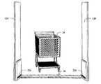
도 2는 본 발명의 원리들에 따라 구성된 도 1의 예시적인 EAS 시스템을 이송하는 카트의 측면 사시도.
도 3은 본 발명의 원리들에 따라 구성된 도 1의 예시적인 EAS 시스템을 이송하는 카트의 전방 사시도.
도 4는 본 발명의 원리들에 따라 구성된 예시적인 EAS 시스템 제어기의 블록도.
도 5는 본 발명의 원리들에 따른 예시적인 카트 탐지 프로세스의 흐름도.
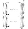
도 6은 본 발명의 원리들에 따라 구성된 적외선 탐지 센서들의 예시적인 구성의 블록도.
도 7은 본 발명의 원리들에 따른 도 6의 적외선 탐지 센서 구성의 예시적인 파이어링 시퀀스를 예시한 흐름도.
도 8은 본 발명의 원리들에 따라 구성된 적외선 탐지 센서들의 대안적인 구성의 블록도.
도 9는 본 발명의 원리들에 따른 도 8의 적외선 탐지 센서 구성의 예시적인 파이어링 시퀀스를 예시한 흐름도.
도 10은 본 발명의 원리들에 따른 도 1의 예시적인 EAS 시스템의 센서 빔들을 모호하지 않게 통과하는 카트의 측면 사시도.
도 11은 본 발명의 원리들에 따른 도 1의 예시적인 EAS 시스템의 적어도 하나의 센서 빔을 모호하게 하는 카트의 측면 사시도.
도 12는 본 발명의 원리들에 따른 예시적인 차단 센서 탐지 프로세스의 흐름도.
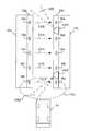
도 13은 PIR(passive infrared) 탐지기의 시야 내에서 EAS 탐지 시스템에 진입하는 카트의 상면도.
도 14는 본 발명의 원리들에 따른 예시적인 물체 탐지 프로세스의 흐름도.A more complete understanding of the invention, and its accompanying advantages and features, will be more readily understood with reference to the following detailed description when considered in conjunction with the accompanying drawings.
1 is a block diagram of an exemplary electronic article surveillance (EAS) detection system with area entry detection, metal detection, cart detection and personnel counting capabilities configured in accordance with the principles of the present invention.
2 is a side perspective view of a cart carrying the exemplary EAS system of FIG. 1 constructed in accordance with the principles of the present invention;
3 is a front perspective view of a cart carrying the exemplary EAS system of FIG. 1 constructed in accordance with the principles of the present invention;
4 is a block diagram of an exemplary EAS system controller constructed in accordance with the principles of the present invention.
5 is a flow diagram of an exemplary cart detection process in accordance with the principles of the present invention.
6 is a block diagram of an exemplary configuration of infrared detection sensors constructed in accordance with the principles of the present invention.
7 is a flow chart illustrating an exemplary firing sequence of the infrared detection sensor configuration of FIG. 6 in accordance with the principles of the invention.
8 is a block diagram of an alternative configuration of infrared detection sensors constructed in accordance with the principles of the present invention.
9 is a flow chart illustrating an exemplary firing sequence of the infrared detection sensor configuration of FIG. 8 in accordance with the principles of the present invention.
10 is a side perspective view of a cart unambiguously passing through the sensor beams of the exemplary EAS system of FIG. 1 in accordance with the principles of the present invention.
11 is a side perspective view of a cart obscuring at least one sensor beam of the exemplary EAS system of FIG. 1 in accordance with the principles of the present invention.
12 is a flow diagram of an exemplary cutoff sensor detection process in accordance with the principles of the invention.
13 is a top view of a cart entering the EAS detection system within the field of view of a passive infrared (PIR) detector.
14 is a flow diagram of an exemplary object detection process in accordance with the principles of the present invention.
본 발명의 실시예에 따라 예시적인 실시예들을 상세히 기술하기 이전에, 실시예들은 주로 EAS 검문 영역 액세스 포인트 근처에 위치된 "PIR(passive infrared)" 탐지기의 시야에 진입하는 카트 또는 유모차와 같은 대상물의 존재를 독립적으로 탐지하기 위한 시스템 및 방법을 구현하는 것에 관련되는 장치 컴포넌트들 및 프로세싱 단계들의 조합들 내에 있다는 것이 주의된다. PIR 탐지기는 대상물이 EAS 검문 영역에 진입하기 이전에 대상물을 탐지하도록 위치되고, 그에 의해 탐지 성능들을 차폐하는 EAS 마커를 갖는 EAS 시스템의 감도 레벨을 조정하기 보다는 오히려 시스템이 타임아웃 모드를 개시하도록 허용한다. 대상물을 탐지시에, PIR 탐지기는 금속 포일 백 탐지 시스템(metal foil bag detection system) 내에서 타이머를 개시하고 금속 카트로 인한 잘못된 알람을 감소시키기 위해 미리 결정된 시간 기간 동안 알람 신호를 억제하거나 금속 탐지를 억제한다. 미리 결정된 시간 기간은 금속 카트가 초기 PIR 탐지 지점으로부터 EAS 검문 영역 내에 위치되는 적외선 바퀴 탐지기를 통해, 즉 바퀴달린 디바이스가 존재하는지 여부에 관한 결정이 내려질 수 있는 바퀴 탐지기 내의 지점으로 이동하는데 예상되는 시간의 양에 대해 설정된다.Prior to describing exemplary embodiments in detail in accordance with an embodiment of the present invention, embodiments are primarily intended for objects such as carts or strollers entering the field of view of a "passive infrared" detector located near an EAS check area access point. It is noted that the combination is within combinations of device components and processing steps that relate to implementing a system and method for independently detecting the presence of a. The PIR detector is positioned to detect the object before the object enters the EAS check area, thereby allowing the system to enter a timeout mode rather than adjusting the sensitivity level of the EAS system with an EAS marker that masks detection capabilities. do. Upon detecting the object, the PIR detector suppresses the alarm signal or suppresses the metal detection for a predetermined period of time to start a timer within the metal foil bag detection system and reduce false alarms caused by the metal cart. Suppress The predetermined time period is expected to move the metal cart from the initial PIR detection point to an infrared wheel detector located within the EAS check area, ie to a point within the wheel detector where a determination can be made as to whether a wheeled device is present. Is set for the amount of time.
이에 따라, 시스템 및 방법 컴포넌트들은 여기서의 설명의 이익을 갖는 당업자들에게 쉽게 자명하게 되는 상세들로 본 개시를 모호하게 하지 않도록 본 발명의 실시예들을 이해하는데 적절한 특정한 상세들만을 도시하는 도면들에서 종래의 심볼들에 의해 적절히 표현된다.Accordingly, system and method components are shown in the drawings showing only specific details suitable for understanding embodiments of the invention in order not to obscure the present disclosure with details that will be readily apparent to those skilled in the art having the benefit of the description herein. It is properly represented by conventional symbols.
여기서 이용되는 바와 같이, "제 1" 및 "제 2", "상부" 및 "하부" 등과 같은 상대적인 용어들은 반드시 엔티티들 또는 엘리먼트들 간의 임의의 물리적 또는 논리적 관계 또는 순서를 요구하거나 암시함 없이 하나의 엔티티 또는 엘리먼트를 다른 엔티티 또는 엘리먼트로부터 구분하는데만 이용될 수 있다. As used herein, relative terms such as "first" and "second", "top", "bottom", and the like, must not necessarily imply or imply any physical or logical relationship or order between entities or elements. It can only be used to distinguish an entity or element of a from another entity or element.
본 발명의 일 실시예는 유리하게는 EAS 검문 영역 액세스 포인트 근처에 위치된 "PIR(passive infrared)" 탐지기와 같은 탐지기의 시야에 진입하는 카트 또는 유모차와 같은 대상물의 존재를 탐지하기 위한 시스템 및 방법을 제공한다. PIR 탐지기는 대상물이 EAS 시스템의 검문 영역에 진입하기 이전에 대상물을 탐지하도록 위치된다. PIR 탐지기는 금속 카트가 초기 PIR 탐지 지점으로부터 EAS 검문 영역 내에 위치되는 적외선 바퀴 탐지기를 통해, 즉, 적어도 바퀴달린 디바이스가 존재하는지 여부에 관한 결정이 내려질 수 있는 바퀴 탐지기 내의 지점으로 이동하는데 예상되는 양의 시간으로 사전-프로그래밍되는 타이머를 시작하기 위해 금속 포일 백 탐지 시스템에 신호를 송신한다. 사전-프로그래밍된 양의 시간 동안, EAS 시스템은 EAS 마커 차폐(shield)를 탐지하도록 시도하지 않는다. 대안적으로, 사전-프로그래밍된 양의 시간 동안, EAS 시스템은 EAS 마커 차폐 또는 다른 금속 대상물을 탐지 시에 알람 신호를 생성하지 않는다. 즉, EAS 시스템은 시스템 감도를 억제하거나 알람 신호를 개시하기 보다는 오히려 EAS 검문 영역에 진입하는 대상물을 탐지 시에 타임아웃 기간에 진입한다. EAS 시스템은 검문 영역을 통과하도록 예상되는 대상물의 이동을 탐지하기 위해 EAS 페디스털들의 베이스 상의 플로어 근처에 위치된 적외선 센서 어레이들의 세트 부근에 위치되는 PIR 탐지기와 종래의 EAS 탐지 성능을 조합한다.One embodiment of the present invention advantageously provides a system and method for detecting the presence of an object, such as a cart or stroller, that enters the field of view of a detector, such as a "passive infrared" detector, located near an EAS check area access point. To provide. The PIR detector is positioned to detect the object prior to entering the inspection area of the EAS system. The PIR detector is expected to move the metal cart from the initial PIR detection point to an infrared wheel detector located in the EAS check area, ie to a point in the wheel detector where at least a determination can be made whether a wheeled device is present. A signal is sent to the metal foil back detection system to start a timer that is pre-programmed in positive time. For a pre-programmed amount of time, the EAS system does not attempt to detect the EAS marker shield. Alternatively, for a pre-programmed amount of time, the EAS system does not generate an alarm signal upon detecting the EAS marker shield or other metal object. That is, the EAS system enters a timeout period upon detecting an object entering the EAS check region rather than suppressing system sensitivity or initiating an alarm signal. The EAS system combines conventional EAS detection capabilities with a PIR detector located near a set of infrared sensor arrays located near the floor on the base of the EAS pedestals to detect the movement of the object expected to pass through the inspection area.
이제, 동일한 참조 지시자(designator)들은 동일한 엘리먼트들을 지칭하는 작도들(drawing figures)을 참조하면, 도 1에는 본 발명의 원리들에 따라 구성되고, 예를 들어, 시설 입구에 위치되는 예시적인 EAS 탐지 시스템(10)의 일 구성이 도시된다. EAS 탐지 시스템(10)은 입구(14)의 반대 측면들 상에 한 쌍의 페디스털들(12a, 12b)(총괄하여 페디스털(12)로 언급함)을 포함한다. EAS 탐지 시스템(10)을 위한 하나 또는 그 초과의 안테나들이, 공지된 거리로 이격되어 위치되는 페디스털들(12a 및 12b) 내에 포함될 수 있다. 페디스털들(12)에 위치된 안테나들이 제어 시스템(16)에 전기적으로 결합되고, 이 제어 시스템(16)은 EAS 탐지 시스템(10)의 동작을 제어한다. 시스템 제어기(16)는, 호일-라인드(foil-lined) 가방의 존재를 더욱 정확하게 탐지하기 위해서 금속 탐지기(18), 인원 계수 시스템(20), 적외선 센서 어레이(22) 및 영역 입장 탐지기(23)에 전기적으로 연결된다. 적외선 센서 어레이(22)는 한 쌍의 적외선 센서 패널들(22a, 22b)(총괄적으로 "적외선 센서 어레이(22)"로 지칭됨)을 포함한다. 센서 어레이들의 다른 타입들, 이를 테면, 압력이 인가되는 장소를 나타내는 데이터를 제공하도록 구성되는 압력 감지 매트, 및 이와 유사한 것이 사용될 수 있다는 것이 또한 예상된다.Referring now to drawing figures that refer to the same elements, FIG. 1 is an exemplary EAS detection constructed in accordance with the principles of the present invention, for example located at a facility entrance. One configuration of
금속 탐지기(18)는, 시스템 제어기(16)에 통신가능하게 연결되는, 또는 시스템 제어기(16)로 통합될 수 있는 별개의 유닛일 수 있다. 일 예시적인 금속 탐지기(18)는, 2009년 6월 26일 출원되고 명칭이 "Electronic Article Surveillance System with Metal Detection Capability and Method Therefor,"인 미국 특허 출원 번호 제12/492,309호에 개시되며, 상기 미국 특허 출원의 전체 교시들은 인용에 의해 본원에 포함된다.The
영역 입장 탐지기(23)는 다른 영역 입장 탐지기들 중에서도 PIR 탐지기들을 포함할 수 있다. 영역 입장 탐지기(23)는 적외선 센서 어레이(22) 상에 장착될 수 있다. 일 실시예에 따르면, 영역 입장 탐지기(23)는, 발목(ankle) 레벨에서 또는 하한 레벨로부터 대략 2 인치에서 센서 어레이(22) 상에 위치되는 2개의 PIR 탐지기들을 포함한다. 영역 입장 탐지기(23)가 적외선 센서 패널들의 탐지기 측면 상에 장착될 수 있고 센서 어레이(22)에 높이 방향으로 집중될 수 있고 센서 어레이(22)의 반대 측면들에 측 방향으로 위치될 수 있다. 2개의 PIR 탐지기들은 검문 영역을 통과하는 대상물의 움직임을 탐지하기 위해 함께 동작될 수 있다. 예를 들어, 2개의 PIR 탐지기들은 검문 영역을 안으로 대상물이 입장하고 이후 검문 영역 밖으로 대상물이 퇴장하는 것을 탐지하기 위해 함께 동작될 수 있다. 실시예에 따라, 검문 영역(interrogation zone)을 통과하는데 물체에 의해 걸리는 시간량을 결정하기 위해 두 개의 PIR 탐지기들로부터의 신호들이 비교될 수 있다. 대안적으로, 두 개의 PIR 탐지기들은 검문 영역을 통과하는 물체의 입장(entry) 또는 퇴장(exit)을 탐지하기 위해 개별적으로 동작될 수 있다. 존 입장 탐지기(23)는, PIR 탐지기의 어느 한 쪽이 액세스 포인트로부터 대상물 입장을 탐지하도록, 커튼 스타일 존으로 배열된 PIR 탐지기들을 포함할 수 있다.The
인원 계수 시스템(people counting system)(20)은 오버헤드 인원 계수기와 같은 별도의 디바이스일 수 있거나, 또는 물리적으로 하나 또는 그 초과의 페디스털(pedestal)(12) 내에 위치될 수 있거나 그리고/또는 시스템 제어기(16)에 포함될 수 있다. 인원 계수 시스템은, 소매업자의 입구/출구 위에 대략 8 내지 14 피트(2.5m 내지 4.3m)에 장착된 예컨대 하나 또는 그 초과의 적외선 센서들을 포함할 수 있다. 인원 계수 센서들을 EAS 탐지 페디스털(12)에 포함시키는 것은, 필수적인 동작 정보를 전달하는 간단하고 효과적인 방법을 보장하는 것을 돕는다. 동작시, 인원 계수기는, 미리결정된 영역 안으로의 사람의 이동, 미리결정된 영역을 통과하는 사람의 이동, 또는 미리결정된 영역 밖으로의 사람의 이동을 탐지한다. 상기 정보는, 인원 계수 시스템(20)에 의해, 예컨대 프로그래밍된 마이크로프로세서를 이용하여 수집되고 프로세싱된다. 그런 다음, 종래의 네트워킹 컴포넌트들을 이용하여, 인원 계수 데이터는 EAS 탐지 시스템(10)의 다른 일부분들에 송신될 수 있다. 인원 계수 데이터는 가게의 내부 네트워크를 통과해 또는 인터넷과 같은 광역 네트워크들을 경유해 송신될 수 있고, 여기서 상기 인원 계수 데이터는 정렬(sort)될 수 있고, 보고될 수 있고 그리고 연구될 수 있다.The
이제 도 2 및 도 3을 참조하면, 예시적 EAS 시스템(10)을 수송하는 카트(24)의 사시도들이 제공된다. 도 2로부터 알 수 있듯이, 적외선 센서 어레이들(22)이 바닥으로부터 약 1/4인치(6.4㎜) 내지 2인치(51㎜)의 높이에 페디스털들(12)의 베이스에 위치된다. 적외선 센서 어레이(22)의 길이는, 카트 바퀴와 인간 발 사이에서 적외선 빔(26)에 대한 파손(breakage) 패턴의 구별을 허용하기 위해, 적어도 6-12인치(152㎜-305㎜)여야 한다. 적외선 센서 어레이(22)는, 도 3에 도시된 바와 같이, 센서들이 페디스털들(12) 사이에서 다수의 평행한 빔들(26)을 생성하도록 배열된다. 바닥에 대한 빔들의 근접성 때문에, 빔들(26)은 카트(24), 스트롤러(stroller) 또는 페디스털들(12) 사이를 통과하는 다른 바퀴달린 물체의 바퀴들에 의해 차단된다. 또한, 빔들(26)은 사람이 페디스털들 사이를 걸을 때 차단된다. 그러나, 빔들(26)을 통과해 걷는 사람에 대한 파손 패턴은 빔들(26)을 통과해 구르는 카트(24)의 파손 패턴과 상이하다.Referring now to FIGS. 2 and 3, perspective views of a
예를 들어, 카트(24)의 바퀴들은 절대 바닥을 떠나지 않기 때문에, 카트(24)는 순차적으로 빔들(26)을 차단할 것이고, 각각의 빔(26)을 통과할 것이다. 대조적으로, 빔들(26)을 통과하여 걷는 사람은 동시에 수 개의 빔들(26)을 차단(break)할 수 있으며, 어레이(22)의 각각의 빔(26)을 반드시 차단할 필요는 없다. 이들 차단 패턴들의 차들을 인식함으로써, 본 발명의 실시예는 카트(24) 또는 유모차(stroller)와 다른 금속성 대상물들을 구분할 수 있다. 시스템은 이것의 금속 호일-라이닝된 가방 탐지의 민감성 및 정확성을 증가시키기 위하여 이 정보를 사용한다. 시스템 제어기(16)와 결합한 적외선 센서 어레이(22)의 동작이 하기에서 더욱 상세히 논의된다.For example, since the wheels of the
이제 도 4를 참고하여, 예시적인 EAS 시스템 제어기(16)는 제어기(28)(예를 들어, 프로세서 또는 마이크로프로세서), 전력원(30), 트랜시버(32), 메모리(34)(비휘발성 메모리, 휘발성 메모리 또는 이들의 조합물을 포함할 수 있음), 통신 인터페이스(36) 및 알람(38)을 포함할 수 있다. 제어기(28)는 무선 통신들, 메모리(34)로의 데이터의 저장, 다른 디바이스들로의 저장된 데이터의 통신 및 알람(38)의 활성화를 제어한다. 배터리 또는 AC 파워와 같은 전력원(30)은 EAS 제어 시스템(16)에 전기를 공급한다. 알람(38)은 EAS 시스템(10)의 검문 영역(interrogation zone) 내의 금속 및/또는 EAS 마커를 탐지하는 것에 응답하여, 시각적 및/또는 청각적 경보를 제공하기 위한 소프트웨어 및 하드웨어를 포함할 수 있다.Referring now to FIG. 4, exemplary
트랜시버(32)는 하나 또는 그 초과의 송신 안테나들(42)에 전기적으로 결합되는 송신기(40) 및 하나 또는 그 초과의 수신 안테나들(46)에 전기적으로 결합되는 수신기(44)를 포함할 수 있다. 대안적으로, 송신 안테나(42) 및 수신 안테나(46) 양자 모두로서 단일 안테나 또는 안테나들의 쌍이 사용될 수 있다. 송신기(40)는 EAS 시스템(10)의 검문 영역 내의 EAS 마커에 "동력을 공급하기(energize)" 위하여 송신 안테나(42)를 사용하는 무선 주파수 신호를 송신한다. 수신기(44)는 수신 안테나(46)를 사용하여 EAS 마커의 응답 신호를 탐지한다. 예시적인 시스템(10)이 하나의 페디스털, 예를 들어, 페디스털(12a)에 송신 안테나(42) 및 수신기(44)를, 그리고 다른 페디스털, 예를 들어, 페디스털(12b)에 반사성(reflective) 재료를 포함할 수 있음이 또한 고려된다.The
메모리(34)는, 검문 영역 내의 금속의 존재를 탐지하기 위한 금속 탐지 모듈(48), 검문 영역의 액세스 포인트에 근접한 대상물의 존재를 탐지하기 위한 영역 입장 탐지기(49), 및 탐지된 금속이 카트, 유모차 또는 다른 바퀴 달린 대상물, 예를 들어, 바퀴체어, 손수레(hand-truck) 등인지를 결정하기 위한 카트 탐지 모듈(50)을 포함할 수 있다. 금속 탐지 모듈(48), 영역 입장 탐지기(49) 및 카트 탐지 모듈(50)의 동작은 하기에서 더욱 상세히 설명된다.The
카트 탐지 모듈(50)과 조합하여, 금속 탐지 모듈(48) 및 영역 입장 탐지기(49)는, 통신 인터페이스(36)를 통해 금속 탐지기(18), 인원 계수 시스템(20), 적외선 센서 어레이들(22) 및 영역 입장 탐지기(23)로부터 수신되는 출력 정보를 분석함으로써, 알람(38)을 트리거하는지 여부를 결정하는데 사용된다. 예를 들어, 영역 입장 탐지기(49)가 검문 영역에 근접한 대상물의 존재를 탐지한다면, 제어기(28)는 대상물이 검문 영역에 입장하는 것으로 기대되는 시간량에 대한 타임아웃 기간(timeout period)을 시작하기 위한 신호를 금속 탐지 모듈(48)에 전송한다.In combination with the
타임아웃 기간이 만료된 이후에, 빔 차단 패턴을 통해 카트 탐지 모듈(50)이 사람이 검문 영역을 통과하였음을 탐지하고 금속 탐지기(18)가 금속 실드의 특징들에 들어맞는 금속의 소스를 탐지한다면, 금속 탐지 모듈(48)은 제어기(28)를 통해 알람 신호를 전송함으로써 알람(38)을 트리거할 수 있다. 알람(38)은 보증되는 바에 따라 개인을 모니터링하거나 또는 개인에 접근할 수 있는 가게의 보안요원 또는 다른 허가된 직원에게 경보한다.After the timeout period expires, through the beam blocking pattern, the
대안적으로, 타임아웃 기간이 만료한 이후, 카트 탐지 모듈(50)이 빔 파손 패턴에 기초하여 검문 영역(interrogation zone)을 통한 카트의 통과를 탐지하고, 금속 탐지기(18)가 금속 차폐의 특징에 맞춰진 금속의 소스를 탐지하면, 금속 탐지 모듈(48)은 알람(38)을 트리거링하지 않을 것이다.Alternatively, after the timeout period expires, the
또한, 제어기(28)는 시간의 통과를 모니터링하는 실시간 클록("RTC"(52)에 전기적으로 커플링될 수도 있다. RTC(52)는, 금속 탐지 모듈(48)이 금속 탐지 또는 인원 계수와 같은 이벤트들의 활성화가 미리 결정된 시간 프레임 내에서 발생하는지를 결정하기 위한 타이머로서 작동할 수도 있다. RTC(52)는, 알람의 시간 또는 이벤트 탐지가 로깅될 수도 있도록 시간 스탬프를 생성하기 위해 또한 사용될 수도 있다.The
이제 도 5를 참조하면, 페디스털(12)을 통과하는 대상물이 카트(24) 또는 다른 바퀴달린-디바이스(wheeled-device)인지를 결정하도록 EAS 시스템(10)에 의해 수행되는 예시적인 단계들을 설명하는 흐름도가 제공된다. 시스템 제어기(16)는, 적외선 센서 어레이(22)의 구성에 의존하는 빔 시퀀스를 활성화시킴으로써 적외선 센서 어레이들(22)을 인에이블시킨다 (단계 S102).Referring now to FIG. 5, exemplary steps performed by the
적외선 센서 어레이(22)는 다양한 방식들로 구성될 수도 있다. 예를 들어, 도 6에 도시된 바와 같이, 적외선 센서 어레이(22)는, 송신 컴포넌트들(54a-54j)("송신 컴포넌트(54)"로서 집합적으로 참조됨)만을 포함하는 하나의 센서 패널(22a), 및 수신 컴포넌트들(56a-56j)("수신 컴포넌트(56)"로서 집합적으로 참조됨)만을 포함하는 제 2 센서 패널(22b)을 가질 수도 있다. 도 6이 10개의 쌍들의 적외선 센서들을 도시하지만, 도시된 센서 쌍들의 수가 단지 예시의 목적들을 위한 것이며, 인지가능한 파손 패턴을 신뢰가능하게 생성하는 임의의 수의 센서 쌍들이 구현을 위해 선택될 수도 있음을 유의해야 한다. 예를 들어, 본 발명은 5개의 쌍들의 센서들을 사용하여 만족할만하게 수행하도록 발견된다. 또한, 여기에 설명된 바와 같이, 간격이 바퀴달린 카트 대 사람의 걸음걸이의 결정을 허용하는 한 임의의 센서 간격이 사용될 수 있지만, 본 발명의 일 실시예는 약 2.75 내지 3.00 인치(69.9mm 내지 76.0mm) 이격되게 센서들을 구현한다.The
포커싱된 엘리먼트들을 갖는 센서들이 바람직하지만, 본 발명은 비-포커싱된 엘리먼트들을 이용하여 구현될 수 있다. 또한, 자동 이득 제어("AGC") 회로망이 센서 회로의 부분으로서 이용될 수 있지만, 본 발명은 AGC 회로를 포함하지 않는 센서 회로를 이용하여 구현될 수 있다. 후자의 실시예는, 전자의 실시예와 비교하여 더 신속한 사이클 시간에서의 동작을 허용하며, 이에 의해 개선된 정확성을 제공한다는 것이 확인되었다. 도 6에 도시된 구성에서, 모든 전송 컴포넌트들(54) 및 수신 컴포넌트들은 동시에 활성화된다. 그러므로, 단계(S102)의 빔 시퀀스를 개시하기 위해, 시스템 제어기(16)는 전체 적외선 센서 어레이(22)를 활성화시킨다.Sensors with focused elements are preferred, but the present invention can be implemented using non-focused elements. In addition, although an automatic gain control (“AGC”) network can be used as part of the sensor circuit, the present invention can be implemented using a sensor circuit that does not include an AGC circuit. The latter embodiment has been found to allow operation at faster cycle times as compared to the former embodiment, thereby providing improved accuracy. In the configuration shown in FIG. 6, all transmitting components 54 and receiving components are activated at the same time. Therefore, to initiate the beam sequence of step S102, the
도 7은 적외선 센서 어레이(22)의 대안적인 구성을 예시한다. 도 6에 도시된 어레인지먼트와 유사하게, 모든 전송 컴포넌트들(54)은 동일한 센서 패널(22a) 상에 위치되고, 수신 컴포넌트들(56)은 대향 센서 패널(22b) 상에 위치된다. 그러나, 이러한 구성에서, 제어기(28)는 빠른 속도(rapid pace)로 빔들을 시퀀싱하며, 단일 쌍의 센서들만이 어떠한 일 시점에서 활성화된다. 본 발명의 일 실시예는 200㎐의 시퀀싱 레이트를 이용한다. 예를 들어, 도 7에서, 전송 센서(54a)는 제 1 파이어링 라운드(파이어링 라운드 A) 동안 전송하고, 단지 수신 센서(56a)만이 수신하도록 활성화된다. 제 2 파이어링 라운드(파이어링 라운드 B) 동안, 전송 센서(54b)는 전송하고, 단지 수신 센서(56b)만이 수신하도록 활성화된다. 각각의 쌍의 적외선 센서들은 모든 센서들이 파이어링될 때까지 차례로 활성화되고, 시퀀스는 제 1 쌍의 센서들로 다시 시작한다. 이러한 방식으로, 수신 센서들(56)은 센서 쌍의 대응하는 전송 센서(54)로부터 개시된 신호들만을 수신하도록 보장되며, 이에 의해 인접한 빔들로부터의 잘못된(false) 트리거들을 제거하고, 전체적인 감도를 개선한다. 부가적으로, 이러한 시퀀싱 메커니즘은 (도 6의 센서들과 비교하여) 더 저렴한 적외선 센서들의 이용을 허용하는데, 그 이유는 각각의 빔이 매우 협소한, 포커싱된 빔을 갖도록 ― 이는 적외선 센서 쌍들의 피스-부분(piece-part) 비용을 증가시킴 ― 요구되지 않기 때문이다. 또한, 더 적은 포커싱된 빔의 이용은 전송 센서(54) 및 수신 센서(56)의 정렬을 더 용이하게 한다.7 illustrates an alternative configuration of the
도 8은 적외선 센서 어레이(22)의 대안적 구성을 예시한다. 이 구성에서, 인접한 적외선 빔들(26) 사이의 분별력(discretion)을 향상시키기 위해, 전송 컴포넌트(54) 및 수신 컴포넌트(56)는 적외선 센서 패널(22a)과 적외선 센서 패널(22b) 사이에서 교번된다.8 illustrates an alternative configuration of the
도 9는 적외선 센서 어레이(22)의 다른 대안적 구성을 예시하며, 여기서 도 8의 물리적 구성, 즉 수신 컴포넌트들(56)과 교번되는 전송 컴포넌트들(54)은 도 7에 도시된 파이어링 시퀀스(firing sequence)와 결합되어 인접한 빔들(26) 사이에 보다 큰 분별력을 제공하고 오류 트리거들을 더욱 최소화시킨다.FIG. 9 illustrates another alternative configuration of the
이제 도 5를 참조로, 빔 시퀀스는 어떠한 빔들도 차단되지 않는 한 연속하는 사이클로 실행한다(단계 S102). 시스템 제어기(16)가 빔이 차단되었다는 것을 탐지할 때(단계 S104), 카트 탐지 모듈(50)은 적외선 센서 어레이(22)를 모니터하여 제시된 빔 차단 패턴이 바퀴에 대해 예상되는 패턴과 매칭하는지를 결정한다(단계 S106). 예를 들어, 바퀴에 대해 예상되는 패턴은, 각각의 빔이 모든 빔들에 이르기까지 그리고 이 모든 빔들을 포함하는 주어진 수의 빔들에 대해 순차적으로 차단되는 것일 수 있고 오직 주어진 수의 빔들만이 임의의 시간에 차단된다. 패턴이 바퀴에 대해 예상되는 패턴과 매칭하지 않는 경우, 카트 탐지 모듈(50)은 이 차단 패턴이 걷고있는 사람에 대해 예상되는 패턴과 비교한다(단계 S108). 걷고있는 사람에 대해 예상되는 패턴은, 미리결정된 수까지의 빔들이 차단되고 그리고/또는 어레이의 빔들 모두가 트리거되지 않는 것일 수 있다. 패턴이 걷고있는 사람과 매칭하면, 인원 계수기(20)는 증가하고(단계 S110) 프로세스는 종료된다. 패턴이 걷고 있는 사람에 대해 예상되는 패턴과 매칭하지 않는 경우(단계 S108), 카트 탐지 모듈(50)은 결정 블록(S104)으로 리턴되어 임의의 다른 빔들이 차단되었는지를 탐지하여, 현재 차단 패턴을 변경한다. Referring now to FIG. 5, the beam sequence executes in successive cycles unless any beams are blocked (step S102). When the
결정 블록(S106)으로 리턴하여, 현재 차단 패턴이 바퀴에 대해 예상되는 패턴과 매칭하는 경우, 시스템 제어기(116)는 금속 탐지 모듈(48)이 탐문 영역 내의 금속의 존재를 탐지했는지 여부를 결정한다(단계 S112). 금속 탐지 모듈(48)은 탐문 영역 내에 금속의 존재를 간단히 표시할 수 있으며 혹은 탐지되는 금속의 양에 비례하는 판독 응답을 리턴할 수 있으며, 이 경우, 시스템 제어기(16)는 판독 응답이 카트와 같은 대형 금속 대상물에 의해 발생된 응답을 표시하는 미리결정된 임계치보다 큰지를 결정한다. 금속이 탐지되지 않으면, 프로세스는 종료된다. 그러나, 금속이 존재하면(단계 S112), 시스템 제어기(16)는 금속 탐지 모듈(48)이 금속 차폐의 존재를 표시하는 알람을 발생시키는 것을 방지한다(단계 S114). 유사하게, 금속 탐지 모듈(48)이 탐문 영역에서의 금속을 탐지하고 카트 탐지 모듈(50)이 카트가 존재하지 않는다는 것을 결정하면, 시스템 제어기(16)는 금속 차폐의 존재를 나타내는 알람을 발생시키도록 금속 탐지 모듈(48)에게 지시할 수 있다. 도 5에 예시된 프로세스는 연속적으로 반복될 수 있거나 또는 미리결정된 간격으로 반복될 수 있다.Returning to decision block S106, if the current blocking pattern matches the pattern expected for the wheel, the system controller 116 determines whether the
이제 도 10을 참조로, 도 5의 방법은, 카트가 탐문 영역을 거쳐 실제로 이동하고 있고 적외선 빔들(26)을 차단하는 한, 카트(24) 또는 바퀴달린 디바이스를 정확하게 탐지할 수 있다. 그러나 카트(24)가 도 11에 도시된 것처럼, 페디스털들(12)을 거쳐 중간에 멈춰있는 경우, 혹은 다른 아이템들이 페디스털들(12) 사이에 정지된 채 있는 경우, 하나 또는 그 초과의 센서 쌍들이 블록킹되어, 추후 적절히 기능하지 않는다.Referring now to FIG. 10, the method of FIG. 5 can accurately detect a
이제, 도 12를 참조로, 하나 또는 그 초과의 블록킹된 센서 쌍들을 탐지하기 위해 EAS 시스템(10)에 의해 수행되는 예시적인 단계들을 개시하는 흐름도가 제공된다. 시스템 제어기(16)는 도 5에 상세개시된 카트 탐지 프로세스에서 위에서 처럼 빔 시퀀스를 활성화시킴으로써 적외선 센서 어레이들(22)을 인에이블시킨다(단계 S116). 단일 빔이 차단(단계 S118)되면, 실시간 클록(52)이 카운트다운 타이머를 시작한다(단계 S120).Referring now to FIG. 12, a flowchart is provided that discloses exemplary steps performed by the
카운트타운 타이머는 미리 결정된 양의 시간, 예를 들어, 3초 동안 설정될 수 있다. 카운트타운 타이머는 빔이 중단되자마자 시작된다. 카운트타운 타이머가 최종 카운트(단계 S122), 즉 t=0에 도달하지 않는 한, 카트 탐지 모듈(50)은 센서가 차단되지 않는지를 결정(단계 S124)하기 위해 중단된 센서를 계속해서 모니터링한다. 센서가 차단되지 않은 경우, 시스템 제어기(16)는 센서의 상태를 활성으로 설정(단계 S126)하고 차단된 센서들을 계속해서 모니터링하기 위해 결정 블록으로 복귀(S118)한다. 그러나 차단된 센서가 차단되지 않게 되지 않고 카운트다운 타이머가 최종 카운트에 도달하면(단계 S124), 카트 탐지 모듈(50)은 비활성을 위해 차단된 센서의 상태를 설정하고 카트 탐지 프로세스에서 차단된 센서를 이용하지 않는다(단계 S128). 차단된 센서 프로세스를 반복함으로써 앞서 차단된 센서가 차단되지 않게 되면, 차단된 센서는 활성 상태로 복귀할 수 있다. 카운트다운 타이머의 시작 값은 오류 차단 트리거들을 생성하지 않도록 충분히 크게 설정될 수 있다.The counttown timer may be set for a predetermined amount of time, for example three seconds. The counttown timer starts as soon as the beam stops. As long as the counttown timer does not reach the final count (step S122), i.e. t = 0, the
카트가 검문 영역에서 떠나는 경우, 사람이 검문 영역에 너무 오래 머무는 경우, 또는 어떤 다른 물체가 다수의 센서들을 차단하고 있는 경우 발생할 수 있는 것과 같은 차단된 센서 프로세스가 다수의 빔들이 차단된다고 결정하는 경우, 시스템이 점포 관리자 또는 어떤 다른 지정된 사람에게 시스템 조건을 통보하는 것이 고려된다.A blocked sensor process, such as what might happen if a cart leaves the inspection area, a person stays in the inspection area too long, or if some other object is blocking the multiple sensors, determines that the multiple beams are blocked. It is considered that the system notifies the store manager or any other designated person of the system conditions.
도 13을 참조하면, 적외선 센서 어레이(22) 및 PIR 탐지기(1302, 1304)가 페디스털(12)에 제공된다. 오직 송신 컴포넌트들(54a-54e)(통칭하여 "송신 컴포넌트(54)"로 지칭함)을 포함하는 제1 센서 패널(22a)이 페디스털(12a)의 제 1 측에 제공된다. 오직 수신 컴포넌트들(56a-56e)(통칭하여 "수신 컴포넌트(56)"로 지칭함)을 포함하는 제 2 센서 패널(22b)이 페디스털(12b)의 제2 측에 제공된다. 도 13이 5쌍의 적외선 센서들을 도시하지만, 도시된 센서 쌍들의 수는 단지 예시의 목적을 위한 것이며 인식가능한 파손 패턴을 신뢰가능하게 생성하는 임의의 수의 센서 쌍들이 구현을 위해 선택될 수 있음을 주목해야 한다.Referring to FIG. 13, an
도 13은 선택된 수신 컴포넌트들(56a-56e) 사이의 페디스털의 제 2 측, 즉, 탐지기 측에 제공되는 PIR 탐지기들(1302, 1304)을 도시한다. 예컨대, PIR 탐지기(1302)는 제 1 액세스 포인트에서 PIR 탐지 존(1306)을 모니터링하기 위해서 수신 컴포넌트들(56a 및 56b) 사이에 배치될 수 있다. 제 2 PIR 탐지기(1304)는 제 2 액세스 포인트에서 PIR 탐지 존(1308)을 모니터링하기 위해서 수신 컴포넌트들(56d 및 56e) 사이에 배치될 수 있다. 비록 도 13은 2 개의 PIR 탐지기들을 도시하고 있지만 도시된 PIR 탐지기들의 수는 단지 예시를 위한 것이라는 점이 주시되어야 한다. 예컨대, 시스템은 위에서 설명된 바와 같은 단일 PIR 탐지기를 가지고 동작할 수도 있다.13 shows
일 실시예에 따르면, PIR 탐지기들(1302, 1304) 및 센서 어레이는 바닥 평면으로부터 2인치 미만의 지점에 위치될 수 있다. PIR 탐지기들 및 센서 어레이가 다른 높이들에 위치될 수 있다는 점을 당업자라면 쉽게 인지할 것이다. 도 13에 도시된 바와 같이, 자기장(1210)이 페디스털(12)로부터 측방향으로 나온다. PIR 탐지기(1302)는 대상물이 자기장(1310)에 의해 탐지되기 이전에 PIR 탐지 존(1306)에서 대상물을 탐지하도록 위치된다.According to one embodiment, the
쇼핑 카트(24)의 존재를 탐지하였을 때, PIR 탐지기(1302)는 시스템 제어기(16)(미도시) 내의 금속 포일 백 탐지 시스템에 신호를 전송하여, 쇼핑 카트가 초기 PIR 탐지 지점으로부터 EAS 호출신호 존 내에 위치되는 적외선 센서 어레이(22)를 통과해서 이동하는데 예상되는 시간 양, 즉, 적어도, 바퀴달린 디바이스가 EAS 호출신호 존 내에 존재하는지 여부에 관한 결정이 카트 탐지 모듈(50)에 의해 이루어질 수 있는 센서 어레이(22) 내의 지점으로 이동하는데 예상되는 시간 양을 갖도록 미리 프로그래밍된 타이머를 시작한다. 미리 프로그래밍된 시간 양 동안에는, EAS 시스템은 EAS 마커 차폐를 탐지하려 시도하지 않는다. 대안적으로, EAS 시스템은 금속 대상물이 탐지되는 경우 미리 프로그래밍된 시간 양 동안에는 경고 신호를 억제시킬 수 있다. 예컨대, EAS 시스템은 억제 시스템 민감도보다는 오히려 EAS 호출신호 존에 진입하는 쇼핑 카트(24)를 탐지할 때 또는 경고 신호를 개시할 때 타임 아웃 기간에 들어간다. 본 발명은 EAS 페디스털들의 저부 상에서 바닥 근처에 위치되는 적외선 센서 어레이들의 세트 가까이에 위치되는 PIR 탐지기들(1302, 1304)을 종래의 EAS 탐지 성능들과 결합한다. PIR 탐지기(1302)는 호출신호 존을 통과할 것으로 예상되는 쇼핑 카트(24)의 존재를 탐지한다.Upon detecting the presence of the
일단 타임아웃 기간이 만료하면, 금속 탐지기(18)(미도시)는 금속을 감지하려 시도하거나, 경고(38)(미도시)가 활성된다. 만약, 타임아웃 기간이 만료한 이후에, 카트 탐지 모듈(50)(미도시)은 빔 손상 패턴에 기초하여 쇼핑 카트(24)가 빔들(1312-1320)을 파괴하지 않았음을 탐지하고, 금속 탐지기(18)가 금속 차폐의 특성들에 맞는 금속의 소스를 탐지하면, 금속 탐지 모듈(48)(미도시)은 제어기(28)(미도시)를 통해 경고 신호를 전송함으로써 경고(38)(미도시)를 트리거시킬 수 있다. 경고(38)는 정당한 사유가 있을 때 사람을 모니터링하거나 접근할 수 있는 가게 보안요원 또는 다른 허가된 사람에게 경고한다. 예컨대, 빔 손상 패턴은 빔들(1312-1320) 중 하나 이상을 파괴하는 비-쇼핑 카트 또는 사람 발과 대응할 수 있다.Once the timeout period expires, metal detector 18 (not shown) attempts to detect the metal, or alert 38 (not shown) is activated. If, after the timeout period expires, the cart detection module 50 (not shown) detects that the
대안적으로, 만약, 타임아웃 기간이 만료한 이후에, 카트 탐지 모듈(50)이 빔(1312-1320)의 적절한 손상 패턴에 기초하여 호출신호 존을 쇼핑 카트(24)가 통과함을 탐지하고, 금속 탐지기(18)가 금속 차폐의 특성들에 맞는 금속의 소스를 탐지하면, 금속 탐지 모듈(48)은 경고(38)를 트리거시키지 않을 것이다.Alternatively, if, after the timeout period expires, the
이제 도 14를 참조하면, 금속 탐지 탐지기에 의한 허위 경고 신호들을 억제시키기 위해 EAS 시스템(10)에 의해 수행되는 예시적인 처리를 설명하는 흐름도가 제공된다. 시스템 제어기(16)는 대상물이 PIR 탐지기(1302)에 의해 PIR 탐지 존(1306)에서 탐지되는지 여부를 존 진입 탐지기(49)가 탐지하게 할 수 있다.Referring now to FIG. 14, a flow diagram is provided describing an exemplary process performed by the
대상물(object)이 탐지되면, 실-시간 클럭(52)은 카운트다운 타이머를 시작한다(단계 S1404). 카운트다운 타이머는 미리 결정된 시간 양, 예를 들어 1초, 3초, 1분 등을 위해 설정될 수 있다. 카운트다운 타이머는 대상물이 탐지되자마자 시작된다. 금속, 예컨대 금속 포일이 라이닝된 백(metal foil lined bag)의 존재를 금속 탐지 모듈(48)이 탐지했는지에 대해 결정이 이루어진다(단계 S1406). 금속이 탐지되지 않으면, 시스템은 카운트다운 타이머가 종점(terminal) 카운트(즉, t=0)에 도달되지 않는 한, 금속의 존재를 계속 체크한다(단계 S1408). 만약 종점 카운트에 도달되었다면, 프로세스는 종료(end)(그리고 재시작)한다.If an object is detected, the real-
만약 금속이 단계(S1406)에서 탐지되고, 카트 탐지 모듈(50)이 바퀴의 존재를 탐지하면(단계 S1410), 금속 탐지 모듈(48)은 비활성 상태에서 유지된다(단계 S1412). 대안적으로, 금속 탐지 모듈(48)은 활성 상태에서 유지될 수 있고 그리고 알람(38)은 디스에이블될 수 있다. 만약 바퀴의 존재가 단계 S1410에서 탐지되지 않으면, 시스템은 종점 카운트에 도달될 때까지 바퀴의 존재를 계속 체크한다(단계 S1414). 만약 종점 카운트에 도달되고 그리고 바퀴가 카트 탐지 모듈(50)에 의해 탐지되지 않으면, 금속 탐지 모듈(48)은 활성화된다(단계 S1416). 대안적으로, 알람(38)은 활성화될 수 있다. 당업자는 다른 기술들이 카운트다운 타이머 동안 시스템 응답을 억제하게 하기 위하여 사용될 수 있다는 것을 쉽게 인식할 것이다.If metal is detected in step S1406, and the
본 발명은 하드웨어, 소프트웨어, 또는 하드웨어와 소프트웨어의 조합으로 구현될 수 있다. 임의의 종류의 컴퓨팅 시스템, 또는 여기에 기술된 방법들을 수행하기 위해 적응된 다른 장치는 여기에 기술된 기능들을 수행하기에 적합하다.The present invention can be implemented in hardware, software, or a combination of hardware and software. Any kind of computing system, or other apparatus adapted to perform the methods described herein, is suitable for performing the functions described herein.
하드웨어와 소프트웨어의 통상적인 조합은 하나 또는 그 초과의 프로세싱 엘리먼트들을 가진 특화된 컴퓨터 시스템, 및 로딩되고 실행될 때, 여기에 기술된 방법들을 수행하도록 컴퓨터 시스템을 제어하는 저장 매체 상에 저장된 컴퓨터 프로그램일 수 있다. 본 발명은 또한 컴퓨터 프로그램 물건으로 구현될 수 있고, 상기 컴퓨터 프로그램 물건은 여기에 기술된 방법들의 구현을 가능하게 하는 모든 특징부들을 포함하고, 그리고 컴퓨팅 시스템에 로딩될 때, 이들 방법들을 수행할 수 있다. 저장 매체는 임의의 휘발성 또는 비-휘발성 저장 디바이스를 지칭한다.A typical combination of hardware and software may be a specialized computer system having one or more processing elements, and a computer program stored on a storage medium that, when loaded and executed, controls the computer system to perform the methods described herein. . The invention may also be embodied in a computer program product, which includes all the features that enable implementation of the methods described herein, and when loaded into a computing system, may perform these methods. have. The storage medium refers to any volatile or non-volatile storage device.
본 문맥에서 컴퓨터 프로그램 또는 애플리케이션은, 임의의 언어, 코드 또는 표기법으로, 정보 프로세싱 능력을 갖는 시스템으로 하여금, a) 다른 언어, 코드 또는 표기법으로의 전환; b) 서로 다른 재료 형태에서의 재현 중 하나 또는 양자 모두의 것의 이후에 또는 바로 특정 기능을 수행하게 하도록 의도되는 임의의 표현을 의미한다.A computer program or application in this context may, in any language, code or notation, cause a system having information processing capability to: a) switch to another language, code or notation; b) any expression intended to perform a specific function immediately after or immediately after one or both of representations in different material forms.
부가로, 상기한 것과 반대의 언급이 없다면, 첨부되는 도면들 모두는 스케일을 따르지 않는다는 것을 주목해야 한다. 중요하게는, 본 발명은 본 발명의 사상 또는 본질적인 특성들을 이탈하지 않고 다른 특정한 형태들로 구현될 수 있으며, 이에 따라 본 발명의 범주를 표시하는 것으로서, 이전 명세서를 참조하기 보다는 하기의 청구항들에 대한 참조가 이루어져야 한다.In addition, it should be noted that, unless stated to the contrary, the accompanying drawings do not all follow the scale. Importantly, the present invention may be embodied in other specific forms without departing from the spirit or essential characteristics of the invention, and thus indicates the scope of the invention, rather than referring to the preceding specification, as set forth in the claims below. A reference must be made.
Claims (20)
Translated fromKoreanEAS 서브시스템 ―상기 EAS 서브시스템은 검문 영역(interrogation zone)에서 EAS 마커를 탐지함―;
금속 탐지기 ―상기 금속 탐지기는 상기 검문 영역에 있는 금속 대상물을 탐지함―;
대상물 탐지기 ―상기 대상물 탐지기는 상기 EAS 서브시스템의 엔트리점(entry point) 가까이에 위치된 대상물들을 탐지함―;
상기 대상물 탐지기에 의해 발생된 신호를 수신할 때 카운트다운 시퀀스를 시작하도록 프로그램된 타이머;
센서 어레이를 포함하는 카트 탐지 서브시스템 ―상기 카트 탐지 서브시스템은 상기 센서 어레이의 출력에 기반하여 상기 검문 영역을 통과하는 바퀴달린(wheeled) 디바이스를 탐지하도록 동작함―; 및
상기 EAS 서브시스템, 상기 금속 탐지기, 상기 대상물 탐지기, 상기 타이머 및 상기 카트 탐지 서브시스템에 전기적으로 연결된 프로세서 ―상기 프로세서는 상기 카트 탐지 서브시스템으로부터 출력되는 정보 수집을 개시하기 위해 상기 대상물 탐지기 및 상기 타이머로부터의 신호를 그리고 EAS 마커 차폐의 존재에 기초하여 알람 신호를 발생시킬지 여부를 결정하기 위해 상기 금속 탐지기로부터 출력되는 정보를 수신하도록 프로그램됨―
을 포함하는, 전자 물품 감시(EAS) 마커 차폐를 탐지하기 위한 시스템.A system for detecting electronic item surveillance (EAS) marker shielding,
An EAS subsystem, wherein the EAS subsystem detects an EAS marker in an interrogation zone;
A metal detector, the metal detector detecting a metal object in the check region;
An object detector, the object detector detecting objects located near an entry point of the EAS subsystem;
A timer programmed to start a countdown sequence upon receiving a signal generated by the object detector;
A cart detection subsystem comprising a sensor array, the cart detection subsystem operative to detect a wheeled device passing through the inspection area based on the output of the sensor array; And
A processor electrically connected to the EAS subsystem, the metal detector, the object detector, the timer, and the cart detection subsystem, the processor configured to initiate collection of information output from the cart detection subsystem; Programmed to receive information from and output from the metal detector to determine whether to generate an alarm signal based on the presence of an EAS marker shield;
And a system for detecting electronic article surveillance (EAS) marker shielding.
상기 검문 영역은 한 쌍의 EAS 페디스털들 사이에 위치되며, 각각의 EAS 페디스털은 플로어(floor) 상에 놓이도록 위치설정된 베이스 단부(base end)를 가지며, EAS 페디스털 베이스 단부는,
다수의 적외선 센서 쌍들을 갖는 상기 센서 어레이 ―각각의 적외선 센서 쌍은 하나의 전송 컴포넌트 및 하나의 수신 컴포넌트를 포함하며, 상기 전송 컴포넌트는 상기 쌍의 EAS 페디스털들 중 하나의 EAS 페디스털상에 위치되며, 상기 수신 컴포넌트는 상기 쌍의 EAS 페디스털들 중 다른 하나의 EAS 페디스털 상에 위치되어, 활성화될 때, 각각의 적외선 센서 쌍이 상기 페디스털들 사이에 적외선 빔을 형성함―; 및
센서 어레이 수신 컴포넌트와, 상기 EAS 페디스털의 동일한 면(same side)상에 위치설정되는 패시브 적외선 탐지기를 포함하는 상기 대상물 탐지기
를 포함하는, 전자 물품 감시(EAS) 마커 차폐를 탐지하기 위한 시스템.The method of claim 1,
The checkpoint region is located between a pair of EAS pedestals, each EAS pedestal having a base end positioned to lie on a floor, and the EAS pedestal base end being ,
Said sensor array with multiple infrared sensor pairs, each infrared sensor pair comprising one transmitting component and one receiving component, said transmitting component on one EAS pedestal of said pair of EAS pedestals; Wherein the receiving component is located on the EAS pedestal of the other of the pair of EAS pedestals, and when activated, each pair of infrared sensors forms an infrared beam between the pedestals; ; And
The object detector comprising a sensor array receiving component and a passive infrared detector positioned on the same side of the EAS pedestal
And a system for detecting electronic article surveillance (EAS) marker shielding.
각각의 적외선 빔 및 패시브 적외선 센서는 상기 페디스털 베이스 단부에서 충분히 위쪽에 위치설정되어, 상기 적외선 빔이 상기 페디스털들 사이에서 구르고 있는(rolling) 상기 바퀴달린 디바이스의 바퀴에 의해 차단되고 상기 패시브 적외선 센서가 대상물의 존재를 탐지하는, 전자 물품 감시(EAS) 마커 차폐를 탐지하기 위한 시스템.3. The method of claim 2,
Each infrared beam and passive infrared sensor are positioned sufficiently above the pedestal base end, so that the infrared beam is blocked by wheels of the wheeled device rolling between the pedestals and the A system for detecting electronic goods surveillance (EAS) marker shielding, wherein a passive infrared sensor detects the presence of an object.
각각의 적외선 빔은 상기 플로어에 실질적으로 평행하게 그리고 다른 적외선 빔들에 실질적으로 평행하게 위치설정되는, 전자 물품 감시(EAS) 마커 차폐를 탐지하기 위한 시스템.3. The method of claim 2,
Each infrared beam is positioned substantially parallel to the floor and substantially parallel to other infrared beams.
각각의 적외선 빔 및 상기 대상물 탐지기는 상기 페디스털들의 상기 베이스 단부들 위쪽으로 실질적으로 1/4 인치(6.4mm) 내지 실질적으로 2인치(51mm)의 높이에 위치설정되는, 전자 물품 감시(EAS) 마커 차폐를 탐지하기 위한 시스템.5. The method of claim 4,
Each infrared beam and the object detector are positioned at a height of substantially 1/4 inch (6.4 mm) to substantially 2 inches (51 mm) above the base ends of the pedestals. ) System for detecting marker shielding.
상기 다수의 적외선 센서 쌍들은 동시적으로 활성화되는, 전자 물품 감시(EAS) 마커 차폐를 탐지하기 위한 시스템.3. The method of claim 2,
And the plurality of infrared sensor pairs are simultaneously activated.
상기 EAS 서브시스템의 제 2 엔트리포인트에 가깝게 위치된 제 2 대상물 탐지기를 더 포함하는, 전자 물품 감시(EAS) 마커 차폐를 탐지하기 위한 시스템.The method of claim 1,
And a second object detector positioned proximate the second entry point of the EAS subsystem.
상기 카트 탐지 서브시스템은, 상기 검문 영역을 통과하는 사람과 상기 바퀴달린 디바이스 사이를 구별하도록 작동하며,
상기 구별(differentiation)은 차단된(broken) 적외선 빔들의 패턴을, 걷고 있는 사람에 대해 예상되는 패턴과 바퀴달린 디바이스에 대해 예상되는 패턴 중 하나에 매칭시킴으로써 달성되는, 전자 물품 감시(EAS) 마커 차폐를 탐지하기 위한 시스템.3. The method of claim 2,
The cart detection subsystem is operative to distinguish between the person running through the checkpoint area and the wheeled device,
The differentiation is achieved by matching a pattern of broken infrared beams to one of a pattern expected for a walking person and a pattern expected for a wheeled device. System for detecting
상기 바퀴달린 디바이스에 대해 예상되는 패턴은 각각의 적외선 센서 쌍이 순차적으로 트리거링되는 것을 포함하는, 전자 물품 감시(EAS) 마커 차폐를 탐지하기 위한 시스템.The method of claim 8,
The expected pattern for the wheeled device includes each infrared sensor pair being triggered sequentially.
상기 걷고 있는 사람에 대해 예상되는 패턴은 2개 이상(more than one)의 적외선 센서 쌍이 동시적으로 트리거링되는 것을 포함하는, 전자 물품 감시(EAS) 마커 차폐를 탐지하기 위한 시스템.The method of claim 8,
The expected pattern for the walking person includes the triggering of more than one pair of infrared sensors simultaneously.
상기 프로세서는,
상기 금속 탐지기가 상기 검문 영역에 있는 상기 금속 대상물을 탐지하는 것; 그리고
상기 카트 탐지 서브시스템이, 바퀴달린 디바이스가 상기 검문 영역을 통과하지 않았다는 것
에 반응하여, 알람 신호를 발생시키는, 전자 물품 감시(EAS) 마커 차폐를 탐지하기 위한 시스템.The method of claim 1,
The processor comprising:
The metal detector detects the metal object in the check region; And
The cart detection subsystem indicates that a wheeled device did not pass through the inspection area
Responsive to, generating an alarm signal.
검문 영역에 있는 대상물의 존재를 탐지하는 단계;
카운트다운 타이머를 개시하는 단계;
상기 검문 영역 내에 있는 금속성 대상물을 탐지하는 단계;
바퀴달린 디바이스가 상기 검문 영역을 통과하고 있는지를 결정하는 단계; 및
바퀴달린 디바이스가 상기 검문 영역을 통과하고 있지 않다고 결정하는 것에응답하여 그리고 상기 금속 대상물이 탐지될 때, 상기 카운트다운 타이머의 만료시 EAS 마커 차폐의 존재를 통지하는 경보 신호를 발생시키는 단계
를 포함하는, 전자 물품 감시(EAS) 마커 차폐를 탐지하기 위한 방법.A method for detecting electronic goods surveillance (EAS) marker shielding, the method comprising:
Detecting the presence of an object in the inspection area;
Starting a countdown timer;
Detecting a metallic object within the check region;
Determining whether a wheeled device is passing through the inspection area; And
In response to determining that a wheeled device is not passing through the checkpoint area and when the metal object is detected, generating an alert signal notifying the presence of an EAS marker shield upon expiration of the countdown timer.
A method for detecting electronic article surveillance (EAS) marker shielding, comprising:
상기 검문 영역은 한 쌍의 EAS 페디스털들 사이에 형성되며, 상기 방법은,
상기 바퀴달린 디바이스와 사람을 탐지하기 위해 플로어 상에 위치설정가능한 베이스 단부를 갖는 각각의 EAS 페디스털에 센서 어레이를 배치하는 단계 ―상기 센서 어레이는 다수의 적외선 센서 쌍들을 포함하며, 각각의 적외선 센서 쌍은 하나의 전송 컴포넌트 및 하나의 수신 컴포넌트를 포함하며, 상기 전송 컴포넌트는 상기 쌍의 EAS 페디스털들 중 하나의 EAS 페디스털 상에 위치되며, 상기 수신 컴포넌트는 상기 쌍의 EAS 페디스털들 중 다른 하나의 EAS 페디스털 상에 위치되어, 활성화될 때, 각각의 적외선 센서 쌍이 상기 페디스털들 사이에서, 적외선 빔을 형성함―; 및
센서 어레이 수신 컴포넌트와 동일한 면에서 상기 EAS 페디스털 상에 패시브 적외선 탐지기를 배치하는 단계
를 더 포함하는, 전자 물품 감시(EAS) 마커 차폐를 탐지하기 위한 방법.13. The method of claim 12,
The checkpoint region is formed between a pair of EAS pedestals, the method comprising:
Placing a sensor array on each EAS pedestal having a base end that is positionable on a floor for detecting the wheeled device and a person, the sensor array comprising a plurality of infrared sensor pairs, each infrared The sensor pair includes one transmitting component and one receiving component, the transmitting component being located on an EAS pedestal of one of the pair of EAS pedestals, the receiving component being the EAS pedestal of the pair. Located on the EAS pedestal of the other of the hairs and, when activated, each pair of infrared sensors forms an infrared beam between the pedestals; And
Placing a passive infrared detector on the EAS pedestal in the same plane as the sensor array receiving component
The method for detecting electronic article surveillance (EAS) marker shielding further.
상기 페디스털들 사이에서 굴러가고 있는 바퀴달린 디바이스의 바퀴에 의해 상기 적외선 빔이 차단되고 상기 패시브 적외선 탐지기가 상기 검문 영역에 인접한 대상물의 존재를 탐지할 수 있도록, 상기 페디스털 베이스 단부의 충분히 위쪽에 상기 패시브 적외선 탐지기 및 각각의 적외선 빔을 위치설정하는 단계를 더 포함하는, 전자 물품 감시(EAS) 마커 차폐를 탐지하기 위한 방법.The method of claim 13,
Sufficient at the end of the pedestal base so that the infrared beam is blocked by the wheels of the wheeled device rolling between the pedestals and the passive infrared detector can detect the presence of an object adjacent to the inspection area. Positioning the passive infrared detector and each infrared beam thereon, the method for detecting an electronic article surveillance (EAS) marker shield.
바퀴달린 디바이스가 검문 영역을 통과하는지 여부를 결정하는 단계는, 상기 검문 영역을 통과하는 사람과 바퀴달린 디바이스 사이를 구별하는 단계를 포함하며, 상기 구별하는 단계는 차단된(broken) 적외선 빔들의 패턴을, 걷고 있는 사람에 대해 예상되는 패턴과 바퀴달린 디바이스에 대해 예상되는 패턴 중 하나에 매칭시키는 단계를 포함하는, 전자 물품 감시(EAS) 마커 차폐를 탐지하기 위한 방법.The method of claim 13,
Determining whether the wheeled device passes through the checkpoint area includes distinguishing between a person passing through the checkpoint area and the wheeled device, the step of discriminating a pattern of broken infrared beams. And matching one of the expected pattern for the person walking with the expected pattern for the wheeled device.
상기 센서 어레이 수신 컴포넌트와 동일한 면에서 제 2 패시브 적외선 탐지기를 배치하는 단계를 더 포함하는, 전자 물품 감시(EAS) 마커 차폐를 탐지하기 위한 방법.The method of claim 13,
And positioning a second passive infrared detector in the same plane as the sensor array receiving component.
EAS 서브시스템 ―상기 EAS 서브시스템은 검문 영역에 있는 EAS 마커를 탐지함―;
대상물 탐지기 ―상기 대상물 탐지기는 상기 EAS 서브시스템의 엔트리점에 가까이에 위치됨―;
상기 대상물 탐지기에 의해 생성된 신호의 수신시 카운트다운 시퀀스를 시작하도록 프로그램된 타이머;
통신 인터페이스 ―상기 통신 인터페이스는 상기 금속 탐지기, 상기 대상물 탐지기 및 상기 타이머로부터의 입력들을 수신함―;
센서 어레이를 포함하는 카트 탐지 서브시스템 ―상기 카트 탐지 서브시스템은 상기 센서 어레이의 출력에 기초하여 상기 검문 영역을 통과하는 사람과 바퀴달린 디바이스 사이를 구별하도록 작동함―; 및
상기 EAS 서브시스템, 상기 통신 인터페이스 및 상기 카트 탐지 서브시스템에 전기적으로 연결된 프로세서 ―상기 프로세서는 상기 카트 탐지 시스템으로부터 출력되는 정보 수집을 개시하기 위해 상기 대상물 탐지기 및 상기 타이머로부터의 신호를 그리고 EAS 마커 차폐의 존재에 기초하여 알람 신호를 생성할지 여부를 결정하기 위해 상기 금속 탐지기로부터의 정보를 수신하도록 프로그램됨―
을 포함하는, 금속 탐지기를 이용하기 위한 전자 물품 감시(EAS) 시스템 제어기.An electronic goods surveillance (EAS) system controller for using a metal detector,
An EAS subsystem, wherein the EAS subsystem detects an EAS marker in the inspection area;
An object detector, wherein the object detector is located near an entry point of the EAS subsystem;
A timer programmed to start a countdown sequence upon receipt of a signal generated by the object detector;
A communication interface, the communication interface receiving inputs from the metal detector, the object detector, and the timer;
A cart detection subsystem comprising a sensor array, the cart detection subsystem operative to distinguish between a person and a wheeled device passing through the inspection area based on the output of the sensor array; And
A processor electrically connected to the EAS subsystem, the communication interface and the cart detection subsystem, the processor drawing signals from the object detector and the timer and initiating EAS marker shielding to initiate the collection of information output from the cart detection system; Programmed to receive information from the metal detector to determine whether to generate an alarm signal based on the presence of
An electronic article surveillance (EAS) system controller for using a metal detector, comprising: a.
상기 검문 영역은 한 쌍의 EAS 페디스털들 사이에 형성되며, 각각의 EAS 페디스털은 플로어 상에 놓이도록 위치설정되며, 상기 EAS 페디스털은,
다수의 적외선 센서 쌍들을 포함하는 적외선 센서 어레이 ―각각의 적외선 센서 쌍은 하나의 전송 컴포넌트 및 하나의 수신 컴포넌트를 포함하며, 상기 전송 컴포넌트는 상기 쌍의 EAS 페디스털들 중 하나의 EAS 페디스털상에 위치되며, 상기 수신 컴포넌트는 상기 쌍의 EAS 페디스털들 중 다른 하나의 EAS 페디스털상에 위치되어, 활성화될 때, 각각의 적외선 센서 쌍은 상기 페디스털들 사이에 적외선 빔을 형성함―; 및
센서 어레이 수신 컴포넌트와, 상기 EAS 페디스털의 동일한 면상에 위치설정되는 패시브 적외선 탐지기를 포함하는 상기 대상물 탐지기
를 포함하는, 금속 탐지기를 이용하기 위한 전자 물품 감시(EAS) 시스템 제어기.The method of claim 17,
The checkpoint area is formed between a pair of EAS pedestals, each EAS pedestal positioned to lie on the floor, the EAS pedestal,
An infrared sensor array comprising a plurality of infrared sensor pairs, each infrared sensor pair comprising one transmitting component and one receiving component, wherein the transmitting component is on an EAS pedestal of one of the pair of EAS pedestals; And the receiving component is located on the EAS pedestal of the other of the pair of EAS pedestals, and when activated, each pair of infrared sensors forms an infrared beam between the pedestals. -; And
The object detector comprising a sensor array receiving component and a passive infrared detector positioned on the same side of the EAS pedestal
An electronic article surveillance (EAS) system controller for using a metal detector, comprising: a.
상기 카트 탐지 서브시스템은 차단된(broken) 적외선 빔들의 패턴을, 걷고 있는 사람에 대해 예상되는 패턴과 바퀴달린 디바이스에 대해 예상되는 패턴 중 하나에 매칭시킴으로써 상기 검문 영역을 통과하는 사람과 상기 바퀴달린 디바이스 사이를 구별하는, 금속 탐지기를 이용하기 위한 전자 물품 감시(EAS) 시스템 제어기.The method of claim 18,
The cart detection subsystem is configured to match the pattern of broken infrared beams with one of the expected pattern for a walking person and the expected pattern for a wheeled device, such that the wheeled person and the wheeled vehicle pass through the inspection area. Electronic Goods Surveillance (EAS) system controller for using a metal detector to distinguish between devices.
각각의 적외선 빔 및 패시브 적외선 센서는 상기 페디스털 베이스 단부에서 충분히 위쪽에 위치설정되어, 상기 적외선 빔이 상기 페디스털들 사이에서 구르고 있는(rolling) 상기 바퀴달린 디바이스의 바퀴에 의해 차단되고 상기 패시브 적외선 센서가 대상물의 존재를 탐지하는, 금속 탐지기를 이용하기 위한 전자 물품 감시(EAS) 시스템 제어기.
The method of claim 18,
Each infrared beam and passive infrared sensor are positioned sufficiently above the pedestal base end, so that the infrared beam is blocked by wheels of the wheeled device rolling between the pedestals and the An electronic goods surveillance (EAS) system controller for using a metal detector, wherein a passive infrared sensor detects the presence of an object.
Applications Claiming Priority (3)
| Application Number | Priority Date | Filing Date | Title |
|---|---|---|---|
| US12/892,459 | 2010-09-28 | ||
| US12/892,459US8477032B2 (en) | 2009-11-10 | 2010-09-28 | System and method using proximity detection for reducing cart alarms and increasing sensitivity in an EAS system with metal shielding detection |
| PCT/US2011/001666WO2012047268A1 (en) | 2010-09-28 | 2011-09-28 | System and method using proximity detection for reducing cart alarms and increasing sensitivity in an eas system with metal shielding detection |
Publications (2)
| Publication Number | Publication Date |
|---|---|
| KR20130122629Atrue KR20130122629A (en) | 2013-11-07 |
| KR101869051B1 KR101869051B1 (en) | 2018-06-20 |
Family
ID=44908062
Family Applications (1)
| Application Number | Title | Priority Date | Filing Date |
|---|---|---|---|
| KR1020137011072AExpired - Fee RelatedKR101869051B1 (en) | 2010-09-28 | 2011-09-28 | System and method using proximity detection for reducing cart alarms and increasing sensitivity in an eas system with metal shielding detection |
Country Status (8)
| Country | Link |
|---|---|
| US (1) | US8477032B2 (en) |
| EP (1) | EP2622587B1 (en) |
| KR (1) | KR101869051B1 (en) |
| CN (1) | CN103221982B (en) |
| AU (1) | AU2011312867B2 (en) |
| CA (1) | CA2816282C (en) |
| ES (1) | ES2673487T3 (en) |
| WO (1) | WO2012047268A1 (en) |
Families Citing this family (18)
| Publication number | Priority date | Publication date | Assignee | Title |
|---|---|---|---|---|
| US8816854B2 (en)* | 2009-11-10 | 2014-08-26 | Tyco Fire & Security Gmbh | System and method for reducing cart alarms and increasing sensitivity in an EAS system with metal shielding detection |
| WO2012082298A1 (en) | 2010-12-13 | 2012-06-21 | Welch Allyn, Inc. | Loss prevention system |
| KR101621859B1 (en) | 2011-06-14 | 2016-05-17 | (주)세기시스템 | Metal Detector with Function of Manager |
| US9442018B2 (en)* | 2012-01-20 | 2016-09-13 | Koninklijke Philips N.V. | Method and algorithm for self-learning/auto-commissioning by multiple sensor elements for outdoor lighting application |
| WO2014134046A1 (en) | 2013-02-27 | 2014-09-04 | Welch Allyn, Inc. | Anti-loss for medical devices |
| US9275531B2 (en)* | 2014-06-12 | 2016-03-01 | Tyco Fire & Security Gmbh | Systems and methods for adaptively controlling alarm issuance |
| GB2559924B (en) | 2015-12-02 | 2020-08-26 | Walmart Apollo Llc | Systems and methods of tracking item containers at a shopping facility |
| CA3006056A1 (en) | 2015-12-02 | 2017-06-08 | Walmart Apollo, Llc | Systems and methods of monitoring the unloading and loading of delivery vehicles |
| EP3491629B1 (en)* | 2016-07-26 | 2020-05-20 | Alert Systems ApS | Method, apparatus and system for detecting metal objects in a detection zone |
| CN109478359B (en) | 2016-07-26 | 2020-12-25 | 阿勒特系统公司 | System and method for detecting metal objects in a detection area and readable medium |
| EP3978962A1 (en)* | 2016-08-12 | 2022-04-06 | Gatekeeper Systems, Inc. | Direction crossing detector for containment boundary |
| US10475321B2 (en)* | 2016-12-15 | 2019-11-12 | Walmart Apollo, Llc | Cart wheel failure detection systems and methods |
| DE102017112419B3 (en) | 2017-06-06 | 2018-09-06 | Sick Ag | Access protection system |
| US10557932B1 (en)* | 2018-11-28 | 2020-02-11 | Qualcomm Incorporated | Clock oscillator detection |
| JP6835420B2 (en)* | 2019-08-21 | 2021-02-24 | Necプラットフォームズ株式会社 | Information processing equipment, reading system, information processing method, and program |
| US11704986B2 (en)* | 2020-01-31 | 2023-07-18 | Sensormatic Electronics, LLC | System and method for foil detection using millimeter wave for retail applications |
| US11631310B2 (en) | 2021-07-29 | 2023-04-18 | Control Group Companies Llc | EAS security system incorporating time of flight sensing |
| WO2024194213A1 (en)* | 2023-03-22 | 2024-09-26 | Signify Holding B.V. | Radiofrequency sensing based motion determination arrangement |
Citations (7)
| Publication number | Priority date | Publication date | Assignee | Title |
|---|---|---|---|---|
| DE3217944A1 (en)* | 1982-05-13 | 1983-11-17 | Schupa-Elektro-GmbH + Co KG, 5885 Schalksmühle | Control device for detecting a shopping trolley consisting of ferromagnetic materials |
| JP2003091784A (en)* | 2001-09-19 | 2003-03-28 | Optex Co Ltd | Multistage type active infrared sensor |
| JP2003109130A (en)* | 2001-09-28 | 2003-04-11 | Sun Monitor:Kk | Shoplifting preventing system |
| JP2008158967A (en)* | 2006-12-26 | 2008-07-10 | Atsumi Electric Co Ltd | Multistage beam sensor |
| WO2008125621A1 (en)* | 2007-04-13 | 2008-10-23 | Alert Metalguard Aps | A method, a device and a system for preventing false alarms in a theft-preventing system |
| WO2010005499A2 (en)* | 2008-07-07 | 2010-01-14 | Sensormatic Electronics Corporation | Electronic article surveillance system with metal detection capability and method therefor |
| WO2010083020A1 (en)* | 2009-01-13 | 2010-07-22 | Sensormatic Electronics, LLC | System and method for detection of eas marker shielding |
Family Cites Families (21)
| Publication number | Priority date | Publication date | Assignee | Title |
|---|---|---|---|---|
| US3983552A (en)* | 1975-01-14 | 1976-09-28 | American District Telegraph Company | Pilferage detection systems |
| US4327819A (en)* | 1980-08-01 | 1982-05-04 | Coutta John M | Object detection system for a shopping cart |
| US4539558A (en)* | 1981-11-24 | 1985-09-03 | Shin International, Inc. | Antitheft system |
| DE3217977A1 (en) | 1982-05-13 | 1983-11-17 | Bundesrepublik Deutschland, vertreten durch den Bundesminister der Verteidigung, dieser vertreten durch den Präsidenten des Bundesamtes für Wehrtechnik und Beschaffung, 5400 Koblenz | Device for camouflaging objects against reconnaissance by thermal imagers |
| US5485006A (en)* | 1994-01-28 | 1996-01-16 | S.T.O.P. International (Brighton) Inc. | Product detection system for shopping carts |
| US5495102A (en)* | 1993-10-14 | 1996-02-27 | 989952 Ontario Limited | Shopping cart monitoring system |
| US6310963B1 (en)* | 1994-09-30 | 2001-10-30 | Sensormatic Electronics Corp | Method and apparatus for detecting an EAS (electronic article surveillance) marker using wavelet transform signal processing |
| US6201473B1 (en)* | 1999-04-23 | 2001-03-13 | Sensormatic Electronics Corporation | Surveillance system for observing shopping carts |
| US6542079B1 (en)* | 2000-02-18 | 2003-04-01 | Robert A. Kahl, Sr. | Infrared detection and alarm system for bottom shelf of shopping cart |
| US7100052B2 (en)* | 2001-02-01 | 2006-08-29 | Loran Technologies, Inc. | Electronic vehicle product and personal monitoring |
| US6741177B2 (en)* | 2002-03-28 | 2004-05-25 | Verifeye Inc. | Method and apparatus for detecting items on the bottom tray of a cart |
| US7219838B2 (en)* | 2004-08-10 | 2007-05-22 | Howell Data Systems | System and method for notifying a cashier of the presence of an item in an obscured area of a shopping cart |
| US20060197523A1 (en)* | 2005-03-04 | 2006-09-07 | Assurance Technology Corporation | Magnetic screening system |
| US7619517B2 (en)* | 2005-09-30 | 2009-11-17 | Inet Consulting Limited Company | Alarm for selectively detecting intrusions by persons |
| US7453358B2 (en)* | 2006-02-17 | 2008-11-18 | Pflow Industries, Inc. | Shopping cart conveyor with gated access |
| WO2008028487A1 (en) | 2006-09-07 | 2008-03-13 | Alert Metalguard Aps | A system and a method for electronically monitoring goods |
| HUE036703T2 (en)* | 2009-10-16 | 2018-07-30 | Alert Systems Aps | An electronic anti-theft protection system |
| US8350699B2 (en)* | 2010-05-06 | 2013-01-08 | Sensormatic Electronics, LLC | Method and system for adaptive sliding door pattern cancellation in metal detection |
| US8264353B2 (en)* | 2010-05-06 | 2012-09-11 | Sensormatic Electronics, LLC | Method and system for sliding door pattern cancellation in metal detection |
| US8576045B2 (en)* | 2010-10-15 | 2013-11-05 | Tyco Fire & Security Gmbh | Synchronization of electronic article surveillance systems having metal detection |
| NL2008704A (en)* | 2011-06-20 | 2012-12-28 | Asml Netherlands Bv | Wavefront modification apparatus, lithographic apparatus and method. |
- 2010
- 2010-09-28USUS12/892,459patent/US8477032B2/enactiveActive
- 2011
- 2011-09-28EPEP11773925.0Apatent/EP2622587B1/ennot_activeNot-in-force
- 2011-09-28CNCN201180056518.1Apatent/CN103221982B/ennot_activeExpired - Fee Related
- 2011-09-28ESES11773925.0Tpatent/ES2673487T3/enactiveActive
- 2011-09-28CACA2816282Apatent/CA2816282C/ennot_activeExpired - Fee Related
- 2011-09-28AUAU2011312867Apatent/AU2011312867B2/ennot_activeCeased
- 2011-09-28WOPCT/US2011/001666patent/WO2012047268A1/enactiveApplication Filing
- 2011-09-28KRKR1020137011072Apatent/KR101869051B1/ennot_activeExpired - Fee Related
Patent Citations (7)
| Publication number | Priority date | Publication date | Assignee | Title |
|---|---|---|---|---|
| DE3217944A1 (en)* | 1982-05-13 | 1983-11-17 | Schupa-Elektro-GmbH + Co KG, 5885 Schalksmühle | Control device for detecting a shopping trolley consisting of ferromagnetic materials |
| JP2003091784A (en)* | 2001-09-19 | 2003-03-28 | Optex Co Ltd | Multistage type active infrared sensor |
| JP2003109130A (en)* | 2001-09-28 | 2003-04-11 | Sun Monitor:Kk | Shoplifting preventing system |
| JP2008158967A (en)* | 2006-12-26 | 2008-07-10 | Atsumi Electric Co Ltd | Multistage beam sensor |
| WO2008125621A1 (en)* | 2007-04-13 | 2008-10-23 | Alert Metalguard Aps | A method, a device and a system for preventing false alarms in a theft-preventing system |
| WO2010005499A2 (en)* | 2008-07-07 | 2010-01-14 | Sensormatic Electronics Corporation | Electronic article surveillance system with metal detection capability and method therefor |
| WO2010083020A1 (en)* | 2009-01-13 | 2010-07-22 | Sensormatic Electronics, LLC | System and method for detection of eas marker shielding |
Also Published As
| Publication number | Publication date |
|---|---|
| CA2816282C (en) | 2019-09-24 |
| ES2673487T3 (en) | 2018-06-22 |
| AU2011312867B2 (en) | 2016-01-21 |
| US20110109456A1 (en) | 2011-05-12 |
| WO2012047268A1 (en) | 2012-04-12 |
| CA2816282A1 (en) | 2012-04-12 |
| CN103221982B (en) | 2016-08-10 |
| KR101869051B1 (en) | 2018-06-20 |
| AU2011312867A1 (en) | 2013-05-23 |
| CN103221982A (en) | 2013-07-24 |
| EP2622587A1 (en) | 2013-08-07 |
| EP2622587B1 (en) | 2018-04-11 |
| US8477032B2 (en) | 2013-07-02 |
Similar Documents
| Publication | Publication Date | Title |
|---|---|---|
| KR101869051B1 (en) | System and method using proximity detection for reducing cart alarms and increasing sensitivity in an eas system with metal shielding detection | |
| CA2780318C (en) | System and method for reducing cart alarms and increasing sensitivity in an eas system with metal shielding detection | |
| KR101904915B1 (en) | Method and system for people counting using passive infrared detectors | |
| CA2733924C (en) | Metal detection system with integrated directional people counting system | |
| KR20140040780A (en) | Video enabled electronic article surveillance detection system and method | |
| HK1184587A (en) | System and method using proximity detection for reducing cart alarms and increasing sensitivity in an eas system with metal shielding detection | |
| HK1184587B (en) | System and method using proximity detection for reducing cart alarms and increasing sensitivity in an eas system with metal shielding detection | |
| HK1169879B (en) | System and method for reducing cart alarms and increasing sensitivity in an eas system with metal shielding detection | |
| HK1203098B (en) | Method and system for people counting using passive infrared detectors | |
| HK1154983B (en) | Metal detection system with integrated directional people counting system |
Legal Events
| Date | Code | Title | Description |
|---|---|---|---|
| PA0105 | International application | St.27 status event code:A-0-1-A10-A15-nap-PA0105 | |
| P11-X000 | Amendment of application requested | St.27 status event code:A-2-2-P10-P11-nap-X000 | |
| P13-X000 | Application amended | St.27 status event code:A-2-2-P10-P13-nap-X000 | |
| PG1501 | Laying open of application | St.27 status event code:A-1-1-Q10-Q12-nap-PG1501 | |
| R18-X000 | Changes to party contact information recorded | St.27 status event code:A-3-3-R10-R18-oth-X000 | |
| P11-X000 | Amendment of application requested | St.27 status event code:A-2-2-P10-P11-nap-X000 | |
| P13-X000 | Application amended | St.27 status event code:A-2-2-P10-P13-nap-X000 | |
| PA0201 | Request for examination | St.27 status event code:A-1-2-D10-D11-exm-PA0201 | |
| D13-X000 | Search requested | St.27 status event code:A-1-2-D10-D13-srh-X000 | |
| D14-X000 | Search report completed | St.27 status event code:A-1-2-D10-D14-srh-X000 | |
| E902 | Notification of reason for refusal | ||
| PE0902 | Notice of grounds for rejection | St.27 status event code:A-1-2-D10-D21-exm-PE0902 | |
| T11-X000 | Administrative time limit extension requested | St.27 status event code:U-3-3-T10-T11-oth-X000 | |
| T11-X000 | Administrative time limit extension requested | St.27 status event code:U-3-3-T10-T11-oth-X000 | |
| T11-X000 | Administrative time limit extension requested | St.27 status event code:U-3-3-T10-T11-oth-X000 | |
| P11-X000 | Amendment of application requested | St.27 status event code:A-2-2-P10-P11-nap-X000 | |
| P13-X000 | Application amended | St.27 status event code:A-2-2-P10-P13-nap-X000 | |
| E701 | Decision to grant or registration of patent right | ||
| PE0701 | Decision of registration | St.27 status event code:A-1-2-D10-D22-exm-PE0701 | |
| PR0701 | Registration of establishment | St.27 status event code:A-2-4-F10-F11-exm-PR0701 | |
| PR1002 | Payment of registration fee | St.27 status event code:A-2-2-U10-U12-oth-PR1002 Fee payment year number:1 | |
| PG1601 | Publication of registration | St.27 status event code:A-4-4-Q10-Q13-nap-PG1601 | |
| PR1001 | Payment of annual fee | St.27 status event code:A-4-4-U10-U11-oth-PR1001 Fee payment year number:4 | |
| PC1903 | Unpaid annual fee | St.27 status event code:A-4-4-U10-U13-oth-PC1903 Not in force date:20220613 Payment event data comment text:Termination Category : DEFAULT_OF_REGISTRATION_FEE | |
| PC1903 | Unpaid annual fee | St.27 status event code:N-4-6-H10-H13-oth-PC1903 Ip right cessation event data comment text:Termination Category : DEFAULT_OF_REGISTRATION_FEE Not in force date:20220613 |