KR20130119722A - Smart led lighing control system that support bi-directional communication by using zigbee - Google Patents
Smart led lighing control system that support bi-directional communication by using zigbeeDownload PDFInfo
- Publication number
- KR20130119722A KR20130119722AKR1020120042745AKR20120042745AKR20130119722AKR 20130119722 AKR20130119722 AKR 20130119722AKR 1020120042745 AKR1020120042745 AKR 1020120042745AKR 20120042745 AKR20120042745 AKR 20120042745AKR 20130119722 AKR20130119722 AKR 20130119722A
- Authority
- KR
- South Korea
- Prior art keywords
- light
- control
- controller
- lighting
- central controller
- Prior art date
- Legal status (The legal status is an assumption and is not a legal conclusion. Google has not performed a legal analysis and makes no representation as to the accuracy of the status listed.)
- Ceased
Links
- 230000007175bidirectional communicationEffects0.000titledescription2
- 238000005286illuminationMethods0.000claimsabstractdescription8
- 238000000034methodMethods0.000claimsdescription16
- 230000005540biological transmissionEffects0.000claimsdescription5
- 238000013461designMethods0.000abstractdescription3
- 230000006854communicationEffects0.000description30
- 238000004891communicationMethods0.000description30
- 238000010586diagramMethods0.000description13
- 238000012544monitoring processMethods0.000description12
- 238000009434installationMethods0.000description11
- 238000005516engineering processMethods0.000description7
- 230000014509gene expressionEffects0.000description3
- 238000002955isolationMethods0.000description2
- 238000011161developmentMethods0.000description1
- 230000005611electricityEffects0.000description1
- 238000012423maintenanceMethods0.000description1
- 238000012986modificationMethods0.000description1
- 230000004048modificationEffects0.000description1
Images


Classifications
- H—ELECTRICITY
- H04—ELECTRIC COMMUNICATION TECHNIQUE
- H04Q—SELECTING
- H04Q9/00—Arrangements in telecontrol or telemetry systems for selectively calling a substation from a main station, in which substation desired apparatus is selected for applying a control signal thereto or for obtaining measured values therefrom
- Y—GENERAL TAGGING OF NEW TECHNOLOGICAL DEVELOPMENTS; GENERAL TAGGING OF CROSS-SECTIONAL TECHNOLOGIES SPANNING OVER SEVERAL SECTIONS OF THE IPC; TECHNICAL SUBJECTS COVERED BY FORMER USPC CROSS-REFERENCE ART COLLECTIONS [XRACs] AND DIGESTS
- Y02—TECHNOLOGIES OR APPLICATIONS FOR MITIGATION OR ADAPTATION AGAINST CLIMATE CHANGE
- Y02B—CLIMATE CHANGE MITIGATION TECHNOLOGIES RELATED TO BUILDINGS, e.g. HOUSING, HOUSE APPLIANCES OR RELATED END-USER APPLICATIONS
- Y02B20/00—Energy efficient lighting technologies, e.g. halogen lamps or gas discharge lamps
- Y02B20/40—Control techniques providing energy savings, e.g. smart controller or presence detection
Landscapes
- Engineering & Computer Science (AREA)
- Computer Networks & Wireless Communication (AREA)
- Circuit Arrangement For Electric Light Sources In General (AREA)
Abstract
Translated fromKoreanDescription
Translated fromKorean개시된 기술은, 조명 제어 시스템에 관한 것이다. 보다 구체적으로, 기존의 형광등 및 백열등과 함께 LED 조명이 복수 개로 구성될 경우 이를 제어하기 위한 장치 및 시스템 설계를 이용해 효과적이고 안정적인 조명 제어와 함께 설치가 간편한 시스템 구현이 가능하도록 하는 조명 제어 장치 및 조명 제어 시스템에 관한 것이다.The disclosed technique relates to a lighting control system. More specifically, using a device and system design for controlling a plurality of LED lights in addition to the existing fluorescent and incandescent lamps, the lighting control device and lighting to enable an easy and easy system installation with effective and stable lighting control It relates to a control system.
일반적인 기존의 조명 제어기는 AC(교류)용 조명 제어용인 경우, 벽체에 부착된 제어기가 조명의 온/오프(ON/OFF) 및 아날로그 방식의 위상 제어에 의한 디밍제어를 수행한다.In general, the conventional lighting controller is for AC (AC) lighting control, the controller attached to the wall performs the dimming control by the on / off (ON / OFF) of the lighting and the analog phase control.
한편, 일반적인 조명 제어장치는 사용자 제어 패널이 합쳐진 중앙 제어기와 천정에 설치되는 중간 제어기로 구성되며, 벽체에 연결된 중앙 제어기에서 유선 연결에 의하여 중간 제어기와 연결되는 형태이다.On the other hand, the general lighting control device is composed of a central controller combined with a user control panel and an intermediate controller installed on the ceiling, and is connected to the intermediate controller by a wired connection in the central controller connected to the wall.
최근에는 AC용 조명에서 친환경, 고휘도, 절전 등의 많은 장점을 갖는 LED 조명으로 점차 그 사용 범위가 확대되어 가고 있다.Recently, the use range of LED lighting has many advantages such as eco-friendly, high brightness, power saving, etc. from AC lighting.
이에 따라, 해당기술분야에 있어서는 AC용 조명과 함께 LED 조명을 통합 제어 및 안정적인 조명 제어를 수행할 뿐만 아니라, 관리 및 유지 보수를 위한 조명 제어 시스템에 대한 효과적인 설계에 대한 기술개발이 요구되고 있다.Accordingly, in the relevant technical field, there is a demand for technology development for an effective design of a lighting control system for management and maintenance as well as performing integrated control and stable lighting control of LED lighting along with AC lighting.
[관련기술문헌][Related Technical Literature]
1. 양방향 통신을 지원하고 설정한 규칙에 의해 자동제어되는 기능이 내장된 지능형 엘이디 조명용 전원공급 장치.(공개번호 10-2012-0014962)1.Intelligent LED lighting power supply with bi-directional communication and built-in auto control by established rules. (Publication No. 10-2012-0014962)
2. 양방향 무선통신을 이용한 조명시스템 및 방법(공개번호 10-2011-0130303)2. Lighting system and method using two-way wireless communication (publication number 10-2011-0130303)
개시된 기술이 이루고자 하는 기술적 과제는, 복수의 전등 드라이버를 한번에 제어할 뿐만 아니라, 중앙 제어기와 전등 드라이버를 분리시켜 직렬 형태의 통신용 선(예를 들어, 4선)으로 데이터 송수신 및 제어용 장치의 전원 공급이 수행되도록 함으로써, 전등 드라이버를 실제의 조명 설치 위치에 장착하게 하여 설치 및 수리의 용이함을 갖도록 하기 위한 조명 제어 장치 및 조명 제어 시스템을 제공하기 위한 것이다.The technical problem to be solved by the disclosed technology is not only to control a plurality of light drivers at once, but also to separate the central controller and the light driver, thereby supplying power for transmitting and receiving data and controlling the data in a serial communication line (for example, 4 wires). This is done to provide a light control device and a light control system for mounting the light driver at the actual light installation position to facilitate installation and repair.
또한, 본 발명의 다른 기술적 과제는, 중앙 제어기와 사용자 제어 패널을 분리시킴으로써, 사용자 제어 패널의 설치 위치 및 공간을 자유롭게 할 뿐만 아니라, 사용자 제어 패널로의 전원 공급을 배터리 형태로 제공함으로써, 중앙 제어기의 설치 공간을 더욱 자유롭게 하며, 사용자 제어 패널을 리모컨 형태로 구성가능하도록 하기 위한 조명 제어 장치 및 조명 제어 시스템을 제공하기 위한 것이다.In addition, another technical problem of the present invention, by separating the central controller and the user control panel, not only frees the installation position and space of the user control panel, but also provides a power supply to the user control panel in the form of a battery, the central controller In order to more free the installation space of the user control panel configurable in the form of a remote control to provide a lighting control device and a lighting control system.
상기 기술적 과제를 달성하기 위해 개시된 기술의 제 1측면은, 사용자 제어 패널, 중앙 제어기, 중간 제어기, 복수의 전등 드라이버들을 포함하는 조명 제어 시스템에 있어서, 상기 사용자 제어 패널은 사용자의 조작에 따라 상기 중앙 제어기를 제어하며, 상기 중앙 제어기는 상기 사용자 제어 패널의 제어에 따라 상기 중간 제어기에 조명 제어 신호를 제공하며, 상기 중간 제어기는 상기 중앙제어기와 무선으로 연결되어 상기 조명 제어 신호에 따라 데이터 신호를 형성하며, 상기 복수의 전등 드라이버들에게 유선으로 상기 데이터 신호를 제공하며, 상기 복수의 전등 드라이버들 중 각 전등 드라이버는 상기 데이터 신호에 따라 복수의 LED 드라이버들을 제어하는 조명 제어 시스템을 제공한다.In order to achieve the above technical problem, a first aspect of the disclosed technology is a lighting control system including a user control panel, a central controller, an intermediate controller, and a plurality of light drivers, wherein the user control panel is arranged at the center according to a user's operation. A controller, wherein the central controller provides an illumination control signal to the intermediate controller under control of the user control panel, wherein the intermediate controller is wirelessly connected to the central controller to form a data signal in accordance with the illumination control signal. And providing the data signal to the plurality of light drivers by wire, and each of the plurality of light drivers provides a lighting control system for controlling the plurality of LED drivers according to the data signal.
본 발명의 실시예에 따른 조명 제어 장치 및 조명 제어 시스템은, 기존의 형광등 및 백열등과 함께 LED 조명을 제어하는 기술에 관한 것으로서 효과적이고 안정적인 조명제어와 함께 설치가 간편한 시스템 구현가능한 효과를 제공한다.The lighting control device and the lighting control system according to the embodiment of the present invention, which relates to a technology for controlling the LED lighting with a conventional fluorescent lamp and incandescent lamp, and provides an effect that can be implemented with a simple and effective lighting control system.
또한, 본 발명의 실시예에 따른 조명 제어 장치 및 조명 제어 시스템은, 복수의 전등 드라이버를 한번에 제어할 뿐만 아니라, 중앙 제어기와 전등 드라이버를 분리시켜 직렬 형태의 통신용 선(예를 들어, 4선)으로 데이터 송수신 및 제어용 장치의 전원 공급이 수행되도록 함으로써, 전등 드라이버를 실제의 조명 설치 위치에 장착하게 하여 설치 및 수리의 용이한 효과를 제공한다.In addition, the lighting control device and the lighting control system according to an embodiment of the present invention, not only controls a plurality of light drivers at a time, but also separates the central controller and the light driver in a serial communication line (for example, four wires). By the power supply of the device for data transmission and reception and control to be performed, it is possible to mount the light driver to the actual light installation position to provide an easy effect of installation and repair.
또한, 본 발명의 실시예에 따른 조명 제어 장치 및 조명 제어 시스템은, 중앙 제어기와 사용자 제어 패널을 분리시킴으로써, 사용자 제어 패널의 설치 위치 및 공간을 자유롭게 할 뿐만 아니라, 사용자 제어 패널로의 전원 공급을 배터리 형태로 제공함으로써 중앙 제어기의 설치 공간을 더욱 자유롭게 하며, 사용자 제어 패널을 리모컨 형태로 구성가능한 효과를 제공한다.
In addition, the lighting control device and the lighting control system according to an embodiment of the present invention, by separating the central controller and the user control panel, not only frees the installation position and space of the user control panel, but also provides power supply to the user control panel. By providing in the form of a battery, the installation space of the central controller more freely, and the user control panel in the form of a remote control provides an effect.
도 1은 본 발명의 실시예에 따른 조명 제어 시스템의 구성을 나타내는 도면이다.
도 2는 본 발명의 실시예에 따른 조명 제어 장치의 구성을 나타내는 도면이다.
도 3은 도 1의 중앙 제어 시스템에서의 사용자 제어 패널의 구성의 제 1 실시예를 나타내는 도면이다.
도 4는 도 1의 중앙 제어 시스템에서의 사용자 제어 패널의 구성의 제 2 실시예를 나타내는 도면이다.
도 5는 도 1의 중앙 제어 시스템에서의 중앙 제어기의 구성을 나타내는 도면이다.
도 6은 도 1의 중앙 제어 시스템에서의 중간 제어기를 설명하기 위한 도면이다.
도 7은 도 1의 중앙 제어 시스템에서의 중간 제어기의 구성을 나타내는 도면이다.
도 8은 도 1의 중앙 제어 시스템에서의 전등 드라이버의 구성을 나타내는 도면이다.
도 9는 도 8에 적용가능한 LED 조명의 전력량 모니터링 기능을 수행하는 회로를 나타내는 도면이다.1 is a view showing the configuration of a lighting control system according to an embodiment of the present invention.
2 is a view showing the configuration of a lighting control device according to an embodiment of the present invention.
3 is a view showing a first embodiment of the configuration of the user control panel in the central control system of FIG.
4 is a view showing a second embodiment of the configuration of the user control panel in the central control system of FIG.
FIG. 5 is a diagram illustrating a configuration of a central controller in the central control system of FIG. 1.
FIG. 6 is a diagram for describing an intermediate controller in the central control system of FIG. 1.
7 is a diagram illustrating a configuration of an intermediate controller in the central control system of FIG. 1.
8 is a diagram illustrating a configuration of a light driver in the central control system of FIG. 1.
FIG. 9 is a diagram illustrating a circuit that performs a power amount monitoring function of an LED light applicable to FIG. 8.
개시된 기술에 관한 설명은 구조적 내지 기능적 설명을 위한 실시예에 불과하므로, 개시된 기술의 권리범위는 본문에 설명된 실시예에 의하여 제한되는 것으로 해석되어서는 아니 된다. 즉, 실시예는 다양한 변경이 가능하고 여러 가지 형태를 가질 수 있으므로 개시된 기술의 권리범위는 기술적 사상을 실현할 수 있는 균등물들을 포함하는 것으로 이해되어야 한다.The description of the disclosed technique is merely an example for structural or functional explanation and the scope of the disclosed technology should not be construed as being limited by the embodiments described in the text. That is, the embodiments are to be construed as being variously embodied and having various forms, so that the scope of the disclosed technology should be understood to include equivalents capable of realizing technical ideas.
한편, 본 출원에서 서술되는 용어의 의미는 다음과 같이 이해되어야 할 것이다.Meanwhile, the meaning of the terms described in the present application should be understood as follows.
“제1”, “제2” 등의 용어는 하나의 구성요소를 다른 구성요소로부터 구별하기 위한 것으로 이들 용어들에 의해 권리범위가 한정되어서는 아니 된다. 예를 들어, 제1 구성요소는 제2 구성요소로 명명될 수 있고, 유사하게 제2 구성요소도 제1 구성요소로 명명될 수 있다.The terms " first ", " second ", and the like are used to distinguish one element from another and should not be limited by these terms. For example, the first component may be referred to as a second component, and similarly, the second component may also be referred to as a first component.
어떤 구성요소가 다른 구성요소에 "연결되어" 있다고 언급된 때에는, 그 다른 구성요소에 직접적으로 연결될 수도 있지만, 중간에 다른 구성요소가 존재할 수도 있다고 이해되어야 할 것이다. 반면에, 어떤 구성요소가 다른 구성요소에 "직접 연결되어" 있다고 언급된 때에는, 중간에 다른 구성요소가 존재하지 않는 것으로 이해되어야 할 것이다. 한편, 구성요소들 간의 관계를 설명하는 다른 표현들, 즉 "~사이에"와 "바로 ~사이에" 또는 "~에 이웃하는"과 "~에 직접 이웃하는" 등도 마찬가지로 해석되어야 한다.It is to be understood that when an element is referred to as being "connected" to another element, it may be directly connected to the other element, but there may be other elements in between. On the other hand, when an element is referred to as being "directly connected" to another element, it should be understood that there are no other elements in between. On the other hand, other expressions describing the relationship between the components, such as "between" and "immediately between" or "neighboring to" and "directly neighboring to", should be interpreted as well.
단수의 표현은 문맥상 명백하게 다르게 뜻하지 않는 한 복수의 표현을 포함하는 것으로 이해되어야 하고, "포함하다" 또는 "가지다" 등의 용어는 설시된 특징, 숫자, 단계, 동작, 구성요소, 부분품 또는 이들을 조합한 것이 존재함을 지정하려는 것이지, 하나 또는 그 이상의 다른 특징들이나 숫자, 단계, 동작, 구성요소, 부분품 또는 이들을 조합한 것들의 존재 또는 부가 가능성을 미리 배제하지 않는 것으로 이해되어야 한다.Singular expressions should be understood to include plural expressions unless the context clearly indicates otherwise, and terms such as "include" or "have" refer to features, numbers, steps, operations, components, parts, or parts thereof described. It is to be understood that the combination is intended to be present, but not to exclude in advance the possibility of the presence or addition of one or more other features or numbers, steps, operations, components, parts or combinations thereof.
각 단계들은 문맥상 명백하게 특정 순서를 기재하지 않은 이상 명기된 순서와 다르게 일어날 수 있다. 즉, 각 단계들은 명기된 순서와 동일하게 일어날 수도 있고 실질적으로 동시에 수행될 수도 있으며 반대의 순서대로 수행될 수도 있다.Each step may occur differently from the stated order unless the context clearly dictates the specific order. That is, each step may occur in the same order as described, may be performed substantially concurrently, or may be performed in reverse order.
여기서 사용되는 모든 용어들은 다르게 정의되지 않는 한, 개시된 기술이 속하는 분야에서 통상의 지식을 가진 자에 의해 일반적으로 이해되는 것과 동일한 의미를 가진다. 일반적으로 사용되는 사전에 정의되어 용어들은 관련 기술의 문맥상 가지는 의미와 일치하는 것으로 해석되어야 하며, 본 출원에서 명백하게 정의하지 않는 한 이상적이거나 과도하게 형식적인 의미를 지니는 것으로 해석될 수 없다.
All terms used herein have the same meaning as commonly understood by one of ordinary skill in the art to which the disclosed technology belongs, unless otherwise defined. Terms defined in commonly used dictionaries should be interpreted to be consistent with meaning in the context of the relevant art and can not be construed as having ideal or overly formal meaning unless expressly defined in the present application.
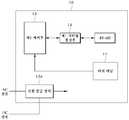
도 1은 본 발명의 실시예에 따른 조명 제어 시스템(1)의 구성을 나타내는 도면이다. 도 1을 참조하면, 조명 제어 시스템(1)은 사용자 제어 패널(10), 중앙 제어기(20), 중간 제어기(30) 및 전등 드라이버(40)를 포함한다.1 is a diagram showing the configuration of a lighting control system 1 according to an embodiment of the present invention. Referring to FIG. 1, the lighting control system 1 includes a
도시된 바와 같이, 전등 드라이버(40)는 복수로 구성되며, 각 전등 드라이버(40)는 LED 드라이버(41) 및 AC용 조명 드라이버(42)로 분리 구성됨으로써, 기존 AC용 조명과, 추가되는 LED 조명의 제어를 동시에 제어가능하도록 설계되어 통합 제어가 가능하며 설치 및 관리의 편의성을 제공한다. 여기서, LED 드라이버(41) 및 AC용 조명 드라이버(42)는 모듈 형태로 제공된다.As shown, the
또한, 중앙 제어기(20)는 무선 또는 유선으로 연결된 적어도 하나 이상으로 중간 제어기(30)를 추가적인 중간 제어기를 더 구비할 수 있다.In addition, the
이하에서는, 조명 제어 시스템(1) 및 조명 제어 장치(2)의 구성을 설명의 편의를 위해 조명 제어 시스템(1)을 중심으로 도시된 도면을 참조하여 구체적으로 살펴보도록 한다.Hereinafter, the configurations of the lighting control system 1 and the lighting control device 2 will be described in detail with reference to the drawings illustrated around the lighting control system 1 for convenience of description.
도 3은 도 1의 중앙 제어 시스템(1)에서의 사용자 제어 패널(10)의 구성의 제 1 실시예를 나타내는 도면이다. 도 1 내지 도 3을 참조하면, 사용자 제어 패널(10)은 터치 패널(11), 전원 공급 장치(12a), 제 1 제어부(13) 및 제 1 시리얼 통신부(14)를 포함하며, 중앙 제어기(20)와 무선 방식으로 연결된다.FIG. 3 is a diagram showing a first embodiment of the configuration of the
터치 패널(11)은 사용자의 조작을 입력받기 위한 사용자 운용 패널로, 사용자의 조작에 따라 입력된 제어 신호를 제 1 제어부(13)로 전송한다.The
전원 공급 장치(12a)는 중앙 제어기(20)와 무선 연결시에는 AC 전원을 제공하는 외부의 전원 공급부를 통해 동작전원을 공급받아 사용자 제어 패널(10)을 동작하도록 한다.The
한편, 전원 공급 장치(12a)는 중앙 제어기(20)와 유선 연결시에는 중앙 제어기(20)로부터 직접 동작전원을 공급받아 사용자 제어 패널(10)을 동작시킨다.On the other hand, the
제 1 제어부(13)는 터치 패널(11)로부터 제어 신호를 수신하여, 중앙 제어기(20)로 제어 신호를 전송하도록 제 1 시리얼 통신부(14)를 제어한다.The
이에 따라, 제 1 시리얼 통신부(14)는 무선연결 시에는 무선 방식 중 지그비(Zigbee) 방식을 통해 중앙 제어부(20)로 제어 신호를 전송한다. 유선 연결 시에는 유선 통신 방식(RS-485)으로 중앙 제어부(20)로 제어 신호를 전송한다Accordingly, the first
도 4는 도 1의 중앙 제어 시스템(1)에서의 사용자 제어 패널(10)의 구성의 제 2 실시예를 나타내는 도면이다. 도 1 내지 도 4를 참조하면, 사용자 제어 패널(10)은 터치 패널(11), 배터리(12b), 배터리전원감시부(12c), 제 1 제어부(13) 및 제 1 시리얼 통신부(14)를 포함한다.4 is a diagram showing a second embodiment of the configuration of the
도 3과 다르게 도 4의 사용자 제어 패널(10)은 내부에 배터리(12b)를 내장하여, 설치 위치의 제약 없이 설치 가능하도록 형성된다.Unlike FIG. 3, the
이에 따라 사용자 제어 패널(10)은 이동 형태의 리모컨으로 활용이 가능하다.Accordingly, the
한편, 배터리전원감시부(12c)는 배터리의 상태를 상기 감시하는 전원감시회로이며, 배터리(12b)가 저 전압일 경우에는 경보를 사용자에게 제공한다.On the other hand, the battery
보다 구체적으로, 배터리전원감시부(12c)는 배터리(12b)가 저 전압으로 감지되면 사용자에게 자체적인 경보를 줌과 동시에 중앙 제어기(20)에 상태를 보고하여 중앙 제어기(20)에 연결된 모니터링서버(미도시)를 통해 모니터링을 할 수 있도록 한다.More specifically, the battery
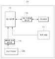
도 5는 도 1의 중앙 제어 시스템(1)에서의 중앙 제어기(30)의 구성을 나타내는 도면이다. 도 1 내지 도 5를 참조하면, 중앙 제어기(20)는 네트워크 모듈(PHY: 21), SMPS(22), 제 2 제어부(23), 제 2 시리얼 통신부(24) 및 LED 제어기 전원 공급부(25)를 포함한다.FIG. 5 is a diagram illustrating a configuration of the
중앙 제어기(20)는 사용자 제어 패널(10)의 제어 신호를 수신하여 조명 제어 신호를 생성한 뒤 중간 제어기(30)에 조명 제어 신호를 제공한다.The
네트워크 모듈(21)은 모니터링서버와의 데이터 송수신을 수행하기 위한 구성 유닛이다.The
SMPS(22)는 상용 전원으로부터 공급되는 교류(AC) 전기를 공급받아 중앙 제어기(20)를 작동시키기 위한 전압으로 변환시켜 중앙 제어기(20)를 동작시킨다.The
제 2 제어부(23)는 제 2 시리얼 통신부(24)로부터 제어 신호를 수신하여 중간 제어기(30)를 제어하기 위한 조명 제어 신호로 변환하여 무선 방식(예를 들어, 지그비 방식)을 통해 중간 제어기(30)로 전송하도록 제 2 시리얼 통신부(24)를 제어한다.The
제 2 제어부(23)는, 도 1에 도시된 바와 같이, 무선 방식으로 사용자 제어 패널(10)과 연결될 경우, 1개의 중앙 제어기(20)에 다수의 사용자 제어 패널(10)이 연결 가능하도록 제어할 수 있다.As shown in FIG. 1, when the
제 2 시리얼 통신부(24)는 유선 또는 무선으로 사용자 제어 패널(10) 및/또는 중간 제어기(30)와의 외부 지원이 가능하도록 하는 구성 유닛이다.The second
LED 제어기 전원 공급부(25)는, 도 2의 조명 제어 장치(2)로 구성될 경우, 추가적으로 구성된다. 이 경우 LED 제어기 전원 공급부(25)는 벽체에 부착되는 사용자 제어 패널(10)과 중앙 제어기(20)간에 유선 연결시 사용자 제어 패널(10)에 전원을 직접 공급하는 역할을 수행한다.The LED
도 6은 도 1의 중앙 제어 시스템(1)에서의 중간 제어기(30)를 설명하기 위한 도면이다. 도 7은 도 1의 중앙 제어 시스템(1)에서의 중간 제어기(30)의 구성을 나타내는 도면이다. 도 1 내지 도 7을 참조하면, 중간 제어기(30)는 중앙 제어기(20)와 무선으로 연결되어 조명 제어 신호를 수신하여 데이터 신호를 생성한 뒤, 복수의 전등 드라이버(40)에게 유선으로 데이터 신호를 제공한다.FIG. 6 is a diagram for explaining the
중간 제어기(30)는 무선통신부(31), 제 1 유선통신부(32), 제 1 전원부(33), 전원공급부(34) 및 제 3 제어부(35)를 포함한다.The
무선통신부(31)는 중앙 제어기(20)와 무선 방식(예를 들어, 지그비 방식)으로 신호 및 데이터 송수신을 수행한다.The
제 1 유선통신부(32)는 적어도 하나 이상의 전등 드라이버(40)에게 유선 방식으로 신호 및 데이터 송수신을 수행한다.The first
제 1 전원부(33)는 상용 전원으로부터 공급되는 교류(AC) 전기를 공급받아 중간 제어기(30)의 동작 전원으로 사용되도록 한다.The
전원공급부(34)는 제 1 전원부(33)로부터 제공되는 전원을 공급받아 필요 전원을 생성하여 복수의 전등 드라이버(40)로 공급한다. 즉, 중간 제어기(30)는 전등 드라이버(40)의 구동 전원을 제공한다.The
제 3 제어부(35)는 중앙 제어기(20)와의 무선 통신을 통해 조명 제어 신호가 수신되도록 무선통신부(31)를 제어하며, 수신된 조명 제어 신호를 데이터 신호로 변환 생성한 뒤, 데이터 신호를 복수의 전등 드라이버들(40)과 유선 통신을 통해 전송되도록 제 1 유선통신부(32)를 제어한다.The
한편, 도 6에 도시된 바와 같이, 중간 제어기(30)와 복수의 전등 드라이버들(40)은 유선으로 연결되며, 2라인의 전원 공급선과 2라인의 데이터 통신 라인에 의해 전원과 데이터 신호를 동시에 제공할 수 있다.Meanwhile, as shown in FIG. 6, the
도 8은 도 1의 중앙 제어 시스템(1)에서의 전등 드라이버(40)의 구성을 나타내는 도면이다. 도 1 내지 도 8을 참조하면, 전등 드라이버(40)는 LED 드라이버(41), AC용 조명 드라이버(42) 및 전등 드라이버 제어부(43)를 포함한다.FIG. 8 is a diagram illustrating a configuration of the
LED 드라이버(41)는 데이터 신호를 수신한 전등 드라이버 제어부(43)에 의해 생성된 LED 드라이버 제어 신호에 의해 LED 조명을 제어한다.The
AC용 조명 드라이버(42)는 데이터 신호를 수신한 전등 드라이버 제어부(43)에 의해 생성된 AC용 조명 드라이버 제어신호에 의해 AC 조명을 제어한다.The
전등 드라이버 제어부(43)는 제 2 유선통신부(43a), 제 2 전원부(43b), 제 4 제어부(43c) 및 포토 커플러(43d)를 포함한다.The light driver control unit 43 includes a second
전등 드라이버 제어부(43)는 데이터 신호를 중간 제어기(30)로부터 수신하여 LED 드라이버(41) 및 AC용 조명 드라이버(42)를 제어하기 위한 LED 드라이버 제어 신호 및 AC용 조명 드라이버 제어신호를 각각 생성한다.The light driver control unit 43 receives a data signal from the
제 2 유선통신부(43a)는 중간 제어기(30)와 유선 방식으로 신호 및 데이터 송수신을 수행한다.The second
제 2 전원부(43b)는 중간 제어기(30)의 전원공급부(34)로부터 필요 전원을 공급받아 제4 제어부 및 제 2 유선통신부(43a)의 동작 전원을 공급한다.The second
제 4 제어부(43c)는 데이터 신호를 중간 제어기(30)로부터 수신하도록 제 2 유선통신부(43a)를 제어한다.The
또한, 제 4 제어부(43c)는 수신된 데이터 신호를 LED 드라이버(41) 및 AC용 조명 드라이버(42)를 제어하기 위한 LED 드라이버 제어 신호 및 AC용 조명 드라이버 제어신호로 각각 변환한다. 이에 따라, 제 4 제어부(43c)는 LED 드라이버 제어 신호 및 AC용 조명 드라이버 제어신호를 각각 LED 드라이버(41)와 AC용 조명 드라이버(42)로 전송하도록 포토 커플러(43d)를 제어한다.In addition, the
또한, 제 4 제어부(43c)는 제 2 전원부(43b)를 통해 공급된 전원을 LED 드라이버(41), AC용 조명 드라이버(42)로 공급하도록 제어한다.In addition, the
여기서, LED 드라이버(41)와 AC용 조명 드라이버(42)로 공급되는 전원은 완전 분리되어 제공됨을 특징으로 한다. 이는 다양하게 사용되는 LED 조명의 종류에 따라 공급 전원이 변하더라도 제어부(43c)의 전원이 분리되어 있기 때문에 대응이 가능할 수 있게 하기 위함이다.
Here, the power supplied to the
포토 커플러(43d)는 제 4 제어부(43c)의 제어에 따라 LED 드라이버 제어 신호를 LED 드라이버(41)로, AC용 조명 드라이버 제어신호를 AC용 조명 드라이버(42)로 분리되어 전송되도록 한다.The
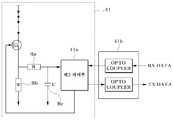
도 9는 도 8에 적용가능한 LED 조명의 전력량 모니터링 기능을 수행하는 회로를 나타내는 도면이다. 도 1 내지 도 9를 참조하면, LED 드라이버(41) 내부에 형성된 제 5 제어부(41a)는 LED 전등의 동작 상태와 전력량 모니터링 및 관리를 수행한다. 즉, 도 9의 LED 드라이버(41) 내부에 형성된 회로 구성과 제 5 제어부(41a)의 제어를 통해 제어가 가능하다.FIG. 9 is a diagram illustrating a circuit that performs a power amount monitoring function of an LED light applicable to FIG. 8. 1 to 9, the
도 8의 제 4 제어부(43c)로부터 수신된 제어 데이터인 LED 드라이버 제어 신호를 아이솔레이션용 옵토 커플러(Opto Coupler)(41b)를 통해 전달받아 제 5 제어부(41a)에서 PWM 신호로 변환하여 LED 조명의 밝기를 조절할 수 있다.The LED driver control signal, which is the control data received from the
또한, 제 5 제어부(41a)는 ADC 포트를 통해 입력받은 전압 신호를 데이터값으로 변환한 후 아이솔레이션용 옵토 커플러(41b)를 통해 중간 제어기(30)로 전송한다.In addition, the
한편, 중간 제어기(30)를 통해 최종적으로 취합된 LED 조명의 밝기 및 상태 신호는 중앙 제어기(20)를 거쳐 모니터링서버에 저장되어 전체적인 LED 조명의 동작 상태를 모니터링할 수 있다.Meanwhile, the brightness and state signals of the LED lights finally collected through the
도 9에서의 Ra는 제 5 제어부(41a)로 입력되는 전원의 전압을 조정하기 위해 사용되며, Rb 및 Rc는 펄스 신호를 평활화시켜서 제 5 제어부(41a)의 ADC 포트로 안정된 전압을 공급하도록 한다.
Ra in FIG. 9 is used to adjust the voltage of the power input to the
이상과 같이, 본 명세서와 도면에는 본 발명의 바람직한 실시 예에 대하여 개시하였으며, 비록 특정 용어들이 사용되었으나, 이는 단지 본 발명의 기술 내용을 쉽게 설명하고 발명의 이해를 돕기 위한 일반적인 의미에서 사용된 것이지, 본 발명의 범위를 한정하고자 하는 것은 아니다. 여기에 개시된 실시 예 외에도 본 발명의 기술적 사상에 바탕을 둔 다른 변형 예들이 실시 가능하다는 것은 본 발명이 속하는 기술 분야에서 통상의 지식을 가진 자에게 자명한 것이다.
As described above, preferred embodiments of the present invention have been disclosed in the present specification and drawings, and although specific terms have been used, they have been used only in a general sense to easily describe the technical contents of the present invention and to facilitate understanding of the invention , And are not intended to limit the scope of the present invention. It will be apparent to those skilled in the art that other modifications based on the technical idea of the present invention can be carried out in addition to the embodiments disclosed herein.
1: 조명 제어 시스템2: 조명 제어 장치
10: 사용자 제어 패널11: 터치 패널
12a: 전원 공급 장치12b: 배터리
12c: 배터리전원감시부13: 제 1 제어부
14: 제 1 시리얼 통신부20: 중앙 제어기
21: 랜연결부22: SMPS
23: 제 2 제어부24: 제 2 시리얼 통신부
25: LED 제어기 전원 공급부30: 중간 제어기
31: 무선통신부32: 제 1 유선통신부
33: 제 1 전원부34: 전원공급부
35: 제 3 제어부40: 전등 드라이버
41: LED 드라이버41a: 제 5 제어부
41b: 옵토 커플러42: AC용 조명 드라이버
43: 전등 드라이버 제어부43a: 제 2 유선통신부
43b: 제 2 전원부43d: 포토 커플러1: lighting control system 2: lighting control unit
10: User Control Panel 11: Touch Panel
12a:
12c: battery power monitoring unit 13: first control unit
14: first serial communication unit 20: central controller
21: LAN connection 22: SMPS
23: second control unit 24: second serial communication unit
25: LED controller power supply 30: intermediate controller
31: wireless communication unit 32: first wired communication unit
33: first power supply 34: power supply
35: third control unit 40: light driver
41:
41b: Optocoupler 42: Light driver for AC
43: light
43b:
Claims (8)
Translated fromKorean상기 사용자 제어 패널은 사용자의 조작에 따라 상기 중앙 제어기를 제어하며,
상기 중앙 제어기는 상기 사용자 제어 패널의 제어에 따라 상기 중간 제어기에 조명 제어 신호를 제공하며,
상기 중간 제어기는 상기 중앙제어기와 무선으로 연결되어 상기 조명 제어 신호에 따라 데이터 신호를 형성하며, 상기 복수의 전등 드라이버들에게 유선으로 상기 데이터 신호를 제공하며,
상기 복수의 전등 드라이버들 중 각 전등 드라이버는 상기 데이터 신호에 따라 복수의 LED 드라이버들을 제어하는 조명 제어 시스템.A lighting control system comprising a user control panel, a central controller, an intermediate controller, a plurality of light drivers,
The user control panel controls the central controller according to a user's operation,
The central controller provides an illumination control signal to the intermediate controller according to the control of the user control panel,
The intermediate controller is wirelessly connected to the central controller to form a data signal according to the illumination control signal, and provides the data signal to the plurality of light drivers by wire.
Wherein each light driver of the plurality of light drivers controls a plurality of LED drivers according to the data signal.
상기 중앙 제어기와 무선 또는 유선으로 연결된 적어도 하나의 추가적인 중간 제어기를 더 구비하는 조명 제어 시스템.The method of claim 1,
And at least one additional intermediate controller wirelessly or wiredly connected to the central controller.
상기 LED 드라이버는 SMPS(Switching Mode Power Supply) 전원에 의해 구동되는 조명 제어 시스템.The method of claim 1,
The LED driver is a lighting control system driven by a switching mode power supply (SMPS) power.
상기 전등 드라이버는 상기 LED 드라이버를 모듈 형태로 포함하는 조명 제어 시스템.The method of claim 1,
The light driver includes the LED driver in the form of a module.
상기 조명 제어 신호의 전송은 지그비(Zigbee) 방식에 의해 수행되는 조명 제어 시스템.The method of claim 1,
The transmission of the lighting control signal is a lighting control system performed by the Zigbee (Zigbee) method.
상기 중앙 제어기는 상기 조명 제어 시스템 외부 네트워크와 접속하는 네트워크 모듈을 더 포함하는 조명 제어 시스템.The method of claim 1,
And the central controller further comprises a network module for connecting with the lighting control system external network.
상기 전등 드라이버는 AC용 조명 드라이버를 더 포함하는 조명 제어 시스템.The method of claim 1,
The light driver further comprises a light driver for AC.
상기 중간 제어기는 상기 전등 드라이버의 구동 전원을 더 포함하는 조명 제어 시스템.The method of claim 1,
The intermediate controller further comprises a drive power source for the light driver.
Priority Applications (1)
| Application Number | Priority Date | Filing Date | Title |
|---|---|---|---|
| KR1020120042745AKR20130119722A (en) | 2012-04-24 | 2012-04-24 | Smart led lighing control system that support bi-directional communication by using zigbee |
Applications Claiming Priority (1)
| Application Number | Priority Date | Filing Date | Title |
|---|---|---|---|
| KR1020120042745AKR20130119722A (en) | 2012-04-24 | 2012-04-24 | Smart led lighing control system that support bi-directional communication by using zigbee |
Publications (1)
| Publication Number | Publication Date |
|---|---|
| KR20130119722Atrue KR20130119722A (en) | 2013-11-01 |
Family
ID=49850649
Family Applications (1)
| Application Number | Title | Priority Date | Filing Date |
|---|---|---|---|
| KR1020120042745ACeasedKR20130119722A (en) | 2012-04-24 | 2012-04-24 | Smart led lighing control system that support bi-directional communication by using zigbee |
Country Status (1)
| Country | Link |
|---|---|
| KR (1) | KR20130119722A (en) |
Cited By (2)
| Publication number | Priority date | Publication date | Assignee | Title |
|---|---|---|---|---|
| KR20150077054A (en) | 2013-12-27 | 2015-07-07 | 삼성에스디에스 주식회사 | Method and system for controlling building using network-map |
| CN104918370A (en)* | 2014-06-11 | 2015-09-16 | 创导(上海)智能技术有限公司 | Intelligent illumination and information interactive system |
- 2012
- 2012-04-24KRKR1020120042745Apatent/KR20130119722A/ennot_activeCeased
Cited By (2)
| Publication number | Priority date | Publication date | Assignee | Title |
|---|---|---|---|---|
| KR20150077054A (en) | 2013-12-27 | 2015-07-07 | 삼성에스디에스 주식회사 | Method and system for controlling building using network-map |
| CN104918370A (en)* | 2014-06-11 | 2015-09-16 | 创导(上海)智能技术有限公司 | Intelligent illumination and information interactive system |
Similar Documents
| Publication | Publication Date | Title |
|---|---|---|
| JP6259126B2 (en) | DC power line communication control device using H-bridge circuit | |
| US11146169B2 (en) | Power factor correction for LED drivers | |
| KR20100132008A (en) | DC power distribution system | |
| CN102843841A (en) | Intelligent LED drive power supply | |
| CN203193980U (en) | Drive circuit for multi-channel dimmable LED (light-emitting diode) lamp tube | |
| KR20120116201A (en) | Led illumination system | |
| CN103582259A (en) | Indoor LED light Bluetooth control system | |
| TW201240525A (en) | Illumination system and energy-saving lamp apparatus thereof | |
| CN203517677U (en) | Lamp adaptor | |
| KR20130119722A (en) | Smart led lighing control system that support bi-directional communication by using zigbee | |
| JP2008228427A (en) | Switching system | |
| KR20130041874A (en) | Lighting controller | |
| US20140049107A1 (en) | Intelligent Lighting and Electrical System | |
| KR20120010415A (en) | Power supply and lighting system including it | |
| CN101965083A (en) | Dimmer remote switch control device applied to light-emitting diode (LED) and using method thereof | |
| WO2013034359A1 (en) | An illumination control system, an illuminating device and a secondary controller | |
| KR20120140323A (en) | Lighting controller | |
| KR101677131B1 (en) | Lighting control system using Bluetooth | |
| US20160336797A1 (en) | Systems and methods for managing power sources for a plurality of luminaires | |
| JP2016081701A (en) | lighting equipment | |
| CN213342781U (en) | Single-fire circuit system | |
| JP2014067486A (en) | Lighting device, lighting fixture, and lighting system | |
| KR20140132491A (en) | Communication module and lighting apparatus comprising the same | |
| CN201992409U (en) | Illuminating system with LED (light-emitting diode) lamp | |
| CN102752924A (en) | Constant-current driving device of illuminating lamp and tandem lamp illuminating system |
Legal Events
| Date | Code | Title | Description |
|---|---|---|---|
| A201 | Request for examination | ||
| PA0109 | Patent application | Patent event code:PA01091R01D Comment text:Patent Application Patent event date:20120424 | |
| PA0201 | Request for examination | ||
| E902 | Notification of reason for refusal | ||
| PE0902 | Notice of grounds for rejection | Comment text:Notification of reason for refusal Patent event date:20130613 Patent event code:PE09021S01D | |
| PG1501 | Laying open of application | ||
| E601 | Decision to refuse application | ||
| PE0601 | Decision on rejection of patent | Patent event date:20131218 Comment text:Decision to Refuse Application Patent event code:PE06012S01D Patent event date:20130613 Comment text:Notification of reason for refusal Patent event code:PE06011S01I |