KR20130115027A - Organic light-emitting diode comprising exciplex forming co-host - Google Patents
Organic light-emitting diode comprising exciplex forming co-hostDownload PDFInfo
- Publication number
- KR20130115027A KR20130115027AKR1020120037560AKR20120037560AKR20130115027AKR 20130115027 AKR20130115027 AKR 20130115027AKR 1020120037560 AKR1020120037560 AKR 1020120037560AKR 20120037560 AKR20120037560 AKR 20120037560AKR 20130115027 AKR20130115027 AKR 20130115027A
- Authority
- KR
- South Korea
- Prior art keywords
- light emitting
- transporting host
- host
- energy
- layer
- Prior art date
- Legal status (The legal status is an assumption and is not a legal conclusion. Google has not performed a legal analysis and makes no representation as to the accuracy of the status listed.)
- Granted
Links
Images


Classifications
- H—ELECTRICITY
- H10—SEMICONDUCTOR DEVICES; ELECTRIC SOLID-STATE DEVICES NOT OTHERWISE PROVIDED FOR
- H10K—ORGANIC ELECTRIC SOLID-STATE DEVICES
- H10K50/00—Organic light-emitting devices
- H10K50/10—OLEDs or polymer light-emitting diodes [PLED]
- H10K50/11—OLEDs or polymer light-emitting diodes [PLED] characterised by the electroluminescent [EL] layers
- H10K50/12—OLEDs or polymer light-emitting diodes [PLED] characterised by the electroluminescent [EL] layers comprising dopants
- H—ELECTRICITY
- H10—SEMICONDUCTOR DEVICES; ELECTRIC SOLID-STATE DEVICES NOT OTHERWISE PROVIDED FOR
- H10K—ORGANIC ELECTRIC SOLID-STATE DEVICES
- H10K50/00—Organic light-emitting devices
- H10K50/10—OLEDs or polymer light-emitting diodes [PLED]
- H10K50/11—OLEDs or polymer light-emitting diodes [PLED] characterised by the electroluminescent [EL] layers
- H—ELECTRICITY
- H10—SEMICONDUCTOR DEVICES; ELECTRIC SOLID-STATE DEVICES NOT OTHERWISE PROVIDED FOR
- H10K—ORGANIC ELECTRIC SOLID-STATE DEVICES
- H10K50/00—Organic light-emitting devices
- H10K50/10—OLEDs or polymer light-emitting diodes [PLED]
- H10K50/14—Carrier transporting layers
- H10K50/15—Hole transporting layers
- H—ELECTRICITY
- H10—SEMICONDUCTOR DEVICES; ELECTRIC SOLID-STATE DEVICES NOT OTHERWISE PROVIDED FOR
- H10K—ORGANIC ELECTRIC SOLID-STATE DEVICES
- H10K50/00—Organic light-emitting devices
- H10K50/10—OLEDs or polymer light-emitting diodes [PLED]
- H10K50/14—Carrier transporting layers
- H10K50/16—Electron transporting layers
- H—ELECTRICITY
- H10—SEMICONDUCTOR DEVICES; ELECTRIC SOLID-STATE DEVICES NOT OTHERWISE PROVIDED FOR
- H10K—ORGANIC ELECTRIC SOLID-STATE DEVICES
- H10K2101/00—Properties of the organic materials covered by group H10K85/00
- H10K2101/10—Triplet emission
- H—ELECTRICITY
- H10—SEMICONDUCTOR DEVICES; ELECTRIC SOLID-STATE DEVICES NOT OTHERWISE PROVIDED FOR
- H10K—ORGANIC ELECTRIC SOLID-STATE DEVICES
- H10K2101/00—Properties of the organic materials covered by group H10K85/00
- H10K2101/30—Highest occupied molecular orbital [HOMO], lowest unoccupied molecular orbital [LUMO] or Fermi energy values
- H—ELECTRICITY
- H10—SEMICONDUCTOR DEVICES; ELECTRIC SOLID-STATE DEVICES NOT OTHERWISE PROVIDED FOR
- H10K—ORGANIC ELECTRIC SOLID-STATE DEVICES
- H10K2101/00—Properties of the organic materials covered by group H10K85/00
- H10K2101/40—Interrelation of parameters between multiple constituent active layers or sublayers, e.g. HOMO values in adjacent layers
- H—ELECTRICITY
- H10—SEMICONDUCTOR DEVICES; ELECTRIC SOLID-STATE DEVICES NOT OTHERWISE PROVIDED FOR
- H10K—ORGANIC ELECTRIC SOLID-STATE DEVICES
- H10K2101/00—Properties of the organic materials covered by group H10K85/00
- H10K2101/90—Multiple hosts in the emissive layer
- H—ELECTRICITY
- H10—SEMICONDUCTOR DEVICES; ELECTRIC SOLID-STATE DEVICES NOT OTHERWISE PROVIDED FOR
- H10K—ORGANIC ELECTRIC SOLID-STATE DEVICES
- H10K85/00—Organic materials used in the body or electrodes of devices covered by this subclass
- H10K85/30—Coordination compounds
- H10K85/321—Metal complexes comprising a group IIIA element, e.g. Tris (8-hydroxyquinoline) gallium [Gaq3]
- H10K85/322—Metal complexes comprising a group IIIA element, e.g. Tris (8-hydroxyquinoline) gallium [Gaq3] comprising boron
- H—ELECTRICITY
- H10—SEMICONDUCTOR DEVICES; ELECTRIC SOLID-STATE DEVICES NOT OTHERWISE PROVIDED FOR
- H10K—ORGANIC ELECTRIC SOLID-STATE DEVICES
- H10K85/00—Organic materials used in the body or electrodes of devices covered by this subclass
- H10K85/30—Coordination compounds
- H10K85/341—Transition metal complexes, e.g. Ru(II)polypyridine complexes
- H10K85/342—Transition metal complexes, e.g. Ru(II)polypyridine complexes comprising iridium
- H—ELECTRICITY
- H10—SEMICONDUCTOR DEVICES; ELECTRIC SOLID-STATE DEVICES NOT OTHERWISE PROVIDED FOR
- H10K—ORGANIC ELECTRIC SOLID-STATE DEVICES
- H10K85/00—Organic materials used in the body or electrodes of devices covered by this subclass
- H10K85/60—Organic compounds having low molecular weight
- H10K85/615—Polycyclic condensed aromatic hydrocarbons, e.g. anthracene
- H10K85/622—Polycyclic condensed aromatic hydrocarbons, e.g. anthracene containing four rings, e.g. pyrene
- H—ELECTRICITY
- H10—SEMICONDUCTOR DEVICES; ELECTRIC SOLID-STATE DEVICES NOT OTHERWISE PROVIDED FOR
- H10K—ORGANIC ELECTRIC SOLID-STATE DEVICES
- H10K85/00—Organic materials used in the body or electrodes of devices covered by this subclass
- H10K85/60—Organic compounds having low molecular weight
- H10K85/631—Amine compounds having at least two aryl rest on at least one amine-nitrogen atom, e.g. triphenylamine
- H—ELECTRICITY
- H10—SEMICONDUCTOR DEVICES; ELECTRIC SOLID-STATE DEVICES NOT OTHERWISE PROVIDED FOR
- H10K—ORGANIC ELECTRIC SOLID-STATE DEVICES
- H10K85/00—Organic materials used in the body or electrodes of devices covered by this subclass
- H10K85/60—Organic compounds having low molecular weight
- H10K85/658—Organoboranes
Landscapes
- Physics & Mathematics (AREA)
- Optics & Photonics (AREA)
- Electroluminescent Light Sources (AREA)
Abstract
Description
Translated fromKorean본 발명은 엑시플렉스를 형성하는 공동 호스트를 포함하는 유기 발광 소자에 관한 것으로서, 상세하게는 발광층에 엑시플렉스를 형성하는 호스트 및 형광 또는 인광 도펀트를 사용한 유기 발광 소자에 관한 것이다. 상기 유기 발광 소자는 유기 발광 조명 또는 유기 발광 디스플레이 장치에 사용될 수 있다.BACKGROUND OF THE INVENTION 1. Field of the Invention The present invention relates to an organic light emitting device including a cavity host forming an exciplex and, more particularly, to an organic light emitting device using an exciplex in a light emitting layer and a fluorescent or phosphorescent dopant. The organic light emitting device may be used in an organic light emitting display or an organic light emitting display device.
유기 발광 소자(organic light emitting diode)는 자발광형 소자로서 시야각이 넓고 콘트라스트가 우수할 뿐만 아니라, 응답시간이 빠르며, 휘도, 구동전압 및 응답속도 특성이 우수하고 다색화가 가능하다는 장점을 가지고 있다.The organic light emitting diode is a self light emitting type device having a wide viewing angle, excellent contrast, fast response time, excellent luminance, driving voltage and response speed characteristics, and multi-coloring.
유기 발광 소자의 구동 원리는 다음과 같다. 상부전극 및 바닥전극 간에 전압을 인가하면, 바닥전극으로부터 주입된 정공이 정공 수송층을 경유하여 발광층으로 이동하고 상부전극으로부터 주입된 전자는 전자 수송층을 경유하여 발광층으로 이동한다. 상기 정공 및 전자(캐리어)는 발광층 영역에서 재결합하여 엑시톤(exciton)을 생성하고 이 엑시톤이 여기 상태에서 기저상태로 변하면서 광이 방출된다.The driving principle of the organic light emitting device is as follows. When a voltage is applied between the upper electrode and the bottom electrode, holes injected from the bottom electrode move to the light emitting layer via the hole transporting layer, and electrons injected from the upper electrode move to the light emitting layer via the electron transporting layer. The holes and the electrons (carriers) recombine in the light emitting layer region to generate excitons, and the light is emitted while the excitons are changed from the excited state to the ground state.
유기 발광 소자의 성능은 매우 발전하여 최근에는 외부양자효율이 29%인 소자뿐만 아니라 롤-오프(roll-off)가 매우 낮은 소자도 발표되었다. 하지만 일반적인 유기 발광 소자의 구동 전압은 아직도 이론적인 값보다 매우 높은 편인데, 이렇게 구동전압이 매우 높게 형성되는 이유는 유기 발광 소자가 바닥전극/정공주입층/정공수송층/발광층/전자수송층/전자주입층/상부전극 순으로 적층된 구조를 가져 각 전극과 유기층 사이 및/또는 유기층들 사이에서 전자 및/또는 정공의 주입 장벽이 생기기 때문인 것으로 알려져 있다. 그리하여 구동전압을 낮추기 위해 에너지 장벽을 낮추거나 없애고 전자와 정공의 전달이 균형을 이루도록 하는 시도가 있었으나 이 경우에도 여전히 발광효율이 낮고 고휘도에서 롤-오프(roll-off)가 크며 구동전압은 이론적인 값에 비하여 매우 높은 편이다.The performance of organic light emitting devices has been remarkably improved, and recently, not only devices with external quantum efficiency of 29% but also devices with extremely low roll-off have been disclosed. However, the driving voltage of a general organic light emitting device is still much higher than a theoretical value. The reason why the driving voltage is formed to be very high is that the organic light emitting device has a structure in which the bottom electrode / hole injection layer / hole transport layer / light emitting layer / Layer / upper electrode are stacked in this order, so that an electron and / or hole injection barrier occurs between each electrode and the organic layer and / or between the organic layers. Thus, in order to lower the driving voltage, attempts have been made to lower or eliminate the energy barrier and to balance the transfer of electrons and holes. However, in this case, the luminous efficiency is still low and the roll-off at a high luminance is large. Value is very high.
이와 같이, 종래의 유기 발광 소자는 구동전압과 발광효율이 동시에 만족스러운 수준에 도달하지 못하여 이를 해결하기 위한 다양한 기술이 필요한 실정이다.As described above, in the conventional organic light emitting device, the driving voltage and the light emitting efficiency can not reach a satisfactory level at the same time, and various techniques for solving the problem are needed.
상기 언급한 바와 같은 문제를 해결하고자, 발광효율이 우수하고 구동전압은 낮은 유기 발광 소자를 제공하고자 한다.In order to solve the above-mentioned problems, an organic light emitting device having excellent light emitting efficiency and low driving voltage is provided.
일 측면에 따라, 바닥전극; 상기 바닥전극과 대향된 상부전극; 및 상기 바닥전극과 상기 상부전극 사이에 개재된 유기층으로서, 엑시플렉스를 형성하는 ⅰ) 정공 수송성 호스트와 ⅱ) 전자 수송성 호스트, 및 상기 정공 수송성 호스트의 삼중항 에너지, 상기 전자 수송성 호스트의 삼중항 에너지 및 상기 엑시플렉스의 삼중항 에너지보다 작은 삼중항 에너지를 갖는 ⅲ) 인광 도펀트를 포함하는 유기층;을 포함하는 유기 발광 소자가 제공된다.According to one aspect, a bottom electrode; An upper electrode facing the bottom electrode; And an organic layer interposed between the bottom electrode and the top electrode, the organic layer comprising: i) a hole transporting host, ii) an electron transporting host, and triplet energy of the hole transporting host, triplet energy of the electron transporting host And (iii) a phosphorescent dopant having triplet energy lower than the triplet energy of the exciplex.
상기 정공 수송성 호스트 및 상기 전자 수송성 호스트는 하기 관계식 (1) 및 (2)를 만족할 수 있다:The hole transporting host and the electron transporting host may satisfy the following relational expressions (1) and (2):
(1) 정공 수송성 호스트의 최저준위 비점유 분자궤도(LUMO)의 에너지 - 전자 수송성 호스트의 최저준위 비점유 분자궤도(LUMO)의 에너지 > 0.2eV,(1) The lowest level of the hole transporting host The energy of the occupied molecular orbital (LUMO) - The lowest level of the electron transporting host The energy of the occupied molecular orbital (LUMO)> 0.2 eV,
(2) 정공 수송성 호스트의 최고준위 점유 분자궤도(HOMO)의 에너지 - 전자 수송성 호스트의 최고준위 점유 분자궤도(HOMO)의 에너지 > 0.2eV.(2) Energy of the highest level occupied molecular orbital (HOMO) of the hole transporting host - Energy of the highest level occupied molecular orbital (HOMO) of the electron transporting host> 0.2 eV.
상기 유기층은 발광층을 포함할 수 있다.The organic layer may include a light emitting layer.
상기 유기층은 발광층, 상기 발광층과 상기 바닥전극 사이에 개재된 정공 수송층 및 상기 발광층과 상기 상부전극 사이에 개재된 전자 수송층을 포함하고, 상기 정공 수송성 호스트, 상기 전자 수송성 호스트 및 상기 인광 도펀트는 상기 발광층에 포함될 수 있다.Wherein the organic layer includes a light emitting layer, a hole transporting layer interposed between the light emitting layer and the bottom electrode, and an electron transporting layer interposed between the light emitting layer and the upper electrode, wherein the hole transporting host, the electron transporting host, .
상기 정공 수송층은 상기 정공 수송성 호스트와 동일한 정공 수송성 물질을 포함할 수 있고, 상기 전자 수송층은 상기 전자 수송성 호스트와 동일한 전자 수송성 물질을 포함할 수 있다.The hole transporting layer may include the same hole transporting material as the hole transporting host, and the electron transporting layer may include the same electron transporting material as the electron transporting host.
상기 정공 수송성 호스트, 상기 전자 수송성 호스트 및 상기 인광 도펀트의 혼합 몰비는 100:30~300:1~100일 수 있다.The mixed mole ratio of the hole transporting host, the electron transporting host and the phosphorescent dopant may be 100: 30 to 300: 1 to 100.
상기 정공 수송성 호스트와 상기 전자 수송성 호스트의 조합은 TCTA:B3PYMPM, TCTA:TPBi, TCTA:3TPYMB, TCTA:BmPyPB, TCTA:BSFM, CBP:B3PYMPM 및 NPB:BSFM 중 1종일 수 있다.The combination of the hole transporting host and the electron transporting host may be one of TCTA: B3PYMPM, TCTA: TPBi, TCTA: 3TPYMB, TCTA: BmPyPB, TCTA: BSFM, CBP: B3PYMPM and NPB: BSFM.
다른 일 측면에 따라, 바닥전극; 상기 바닥전극과 대향된 상부전극; 및 상기 바닥전극과 상기 상부전극 사이에 개재된 유기층으로서, 엑시플렉스를 형성하며 상기 엑시플렉스의 일중항 에너지와 삼중항 에너지의 차이가 0.3eV 미만인 ⅰ) 정공 수송성 호스트와 ⅱ) 전자 수송성 호스트, 및 상기 엑시플렉스의 일중항 에너지보다 작은 일중항 에너지를 갖는 ⅲ) 형광 도펀트를 포함하는 유기층;을 포함하는 유기 발광 소자가 제공된다.According to another aspect, a bottom electrode; An upper electrode facing the bottom electrode; And an organic layer interposed between the bottom electrode and the top electrode, the organic layer forming an exciplex, the difference between singlet energy and triplet energy of the exiflex being less than 0.3 eV, i) a hole transporting host, ii) And an iii) fluorescent dopant having a singlet energy smaller than the singlet energy of the exciplex.
상기 정공 수송성 호스트 및 상기 전자 수송성 호스트는 하기 관계식 (1) 및 (2)를 만족할 수 있다:The hole transporting host and the electron transporting host may satisfy the following relational expressions (1) and (2):
(1) 정공 수송성 호스트의 최저준위 비점유 분자궤도(LUMO)의 에너지 - 전자 수송성 호스트의 최저준위 비점유 분자궤도(LUMO)의 에너지 > 0.2eV,(1) The lowest level of the hole transporting host The energy of the occupied molecular orbital (LUMO) - The lowest level of the electron transporting host The energy of the occupied molecular orbital (LUMO)> 0.2 eV,
(2) 정공 수송성 호스트의 최고준위 점유 분자궤도(HOMO)의 에너지 - 전자 수송성 호스트의 최고준위 점유 분자궤도(HOMO)의 에너지 > 0.2eV.(2) Energy of the highest level occupied molecular orbital (HOMO) of the hole transporting host - Energy of the highest level occupied molecular orbital (HOMO) of the electron transporting host> 0.2 eV.
상기 유기층은 발광층을 포함할 수 있다.The organic layer may include a light emitting layer.
상기 유기층은 발광층, 상기 발광층과 상기 바닥전극 사이에 개재된 정공 수송층 및 상기 발광층과 상기 상부전극 사이에 개재된 전자 수송층을 포함할 수 있고, 상기 정공 수송성 호스트, 상기 전자 수송성 호스트 및 상기 형광 도펀트는 상기 발광층에 포함될 수 있다.The organic layer may include a light emitting layer, a hole transporting layer interposed between the light emitting layer and the bottom electrode, and an electron transporting layer interposed between the light emitting layer and the upper electrode. The hole transporting host, the electron transporting host, May be included in the light emitting layer.
상기 정공 수송층은 상기 정공 수송성 호스트와 동일한 정공 수송성 물질을 포함할 수 있고, 상기 전자 수송층은 상기 전자 수송성 호스트와 동일한 전자 수송성 물질을 포함할 수 있다.The hole transporting layer may include the same hole transporting material as the hole transporting host, and the electron transporting layer may include the same electron transporting material as the electron transporting host.
상기 정공 수송성 호스트, 상기 전자 수송성 호스트 및 상기 형광 도펀트의 혼합 몰비는 100:30~300:1~100일 수 있다.The mixed mole ratio of the hole transporting host, the electron transporting host, and the fluorescent dopant may be 100: 30 to 300: 1 to 100.
상기 정공 수송성 호스트와 상기 전자 수송성 호스트의 조합은 TCTA:B3PYMPM, TCTA:TPBi, TCTA:3TPYMB, TCTA:BmPyPB, TCTA:BSFM, CBP:B3PYMPM 및 NPB:BSFM 중 1종일 수 있다.The combination of the hole transporting host and the electron transporting host may be one of TCTA: B3PYMPM, TCTA: TPBi, TCTA: 3TPYMB, TCTA: BmPyPB, TCTA: BSFM, CBP: B3PYMPM and NPB: BSFM.
다른 일 측면에 따라, 상기 유기 발광 소자를 포함하는 조명이 제공된다.According to another aspect, an illumination including the organic light emitting element is provided.
다른 일 측면에 따라, 상기 유기 발광 소자를 포함하는 디스플레이 장치가 제공된다.According to another aspect, there is provided a display device including the organic light emitting element.
일 측면에 따른 유기 발광 소자는 엑시플렉스를 형성하는 정공 수송성 호스트와 전자 수송성 호스트를 사용함으로써 낮은 구동 전압과 높은 발광 효율을 가지고 고휘도에서 고효율 특성을 나타낸다.The organic light emitting device according to one aspect exhibits high efficiency at a high luminance with a low driving voltage and a high luminous efficiency by using a hole transporting host and an electron transporting host which form an exciplex.
다른 일 측면에 따른 디스플레이 장치 또는 조명은 엑시플렉스를 형성하는 정공 수송성 호스트와 전자 수송성 호스트를 사용한 유기 발광 소자를 포함하여 저전압 고효율 특성이 요구되는 분야에 유용하게 사용될 수 있다.A display device or an illumination according to another aspect may be usefully used in a field where a low-voltage high-efficiency characteristic is required, including a hole transporting host forming an exciplex and an organic light emitting element using an electron transporting host.
도 1은 일 구현예에 따른 유기 발광 소자의 구조를 개략적으로 나타낸 단면도이다.
도 2는 다른 일 구현예에 따른 유기 발광 소자의 구조를 개략적으로 나타낸 단면도이다.
도 3a 및 3b는 각각 참고예 1 및 비교참고예 1에 따른 박막의 광발광 스펙트럼(photoluminescent spectrum)을 나타낸 그래프이다.
도 4a 내지 4f는 참고예 2 내지 6에 따른 박막의 광발광 스펙트럼을 나타낸 그래프이다.
도 5는 실시예 1에 따른 유기 발광 소자의 각 층에 대한 최고준위 점유 분자궤도(HOMO) 및 최저준위 비점유 분자궤도(LUMO)의 에너지를 나타낸 그래프이다.
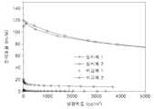
도 6a는 실시예 1 내지 2 및 비교예 1 내지 2에 따른 유기 발광 소자의 전압-전류밀도 관계를 나타낸 그래프이고, 도 6b는 실시예 1 내지 2 및 비교예 1 내지 2에 따른 유기 발광 소자의 전압-발광휘도 관계를 나타낸 그래프이다.
도 7a는 실시예 1 내지 2 및 비교예 1 내지 2에 따른 유기 발광 소자의 외부양자효율을 나타낸 그래프이고, 도 7b는 실시예 1 내지 2 및 비교예 1 내지 2에 따른 유기 발광 소자의 전력효율을 나타낸 그래프이다.1 is a schematic cross-sectional view of a structure of an organic light emitting diode according to an embodiment.
2 is a cross-sectional view schematically showing the structure of an organic light emitting device according to another embodiment.
3A and 3B are graphs showing the photoluminescent spectrum of the thin film according to Reference Example 1 and Comparative Reference Example 1, respectively.
4A to 4F are graphs showing the photoluminescence spectra of the thin films according to Reference Examples 2 to 6.
FIG. 5 is a graph showing the energy of the highest level occupied molecular orbital (HOMO) and the lowest lowest occupied molecular orbital (LUMO) for each layer of the organic light emitting device according to Example 1. FIG.
FIG. 6A is a graph showing voltage-current density relationships of the organic light emitting devices according to Examples 1 and 2 and Comparative Examples 1 and 2, FIG. 6B is a graph showing the relationship between the voltage-current density of the organic light emitting device according to Examples 1 and 2 and Comparative Examples 1 and 2, And a voltage-emission luminance relationship.
FIG. 7A is a graph showing the external quantum efficiency of the organic light emitting device according to Examples 1 and 2 and Comparative Examples 1 and 2, FIG. 7B is a graph illustrating the power efficiency of the organic light emitting device according to Examples 1 and 2 and Comparative Examples 1 and 2 Fig.
도 1은 일 구현예에 따른 유기 발광 소자(10)의 구조를 개략적으로 도시한 단면도이다.FIG. 1 is a cross-sectional view schematically showing the structure of an organic
일 구현예에 따른 유기 발광 소자(10)는, 바닥전극(11); 상기 바닥전극(11)과 대향된 상부전극(19); 및 상기 바닥전극(11)과 상기 상부전극(19) 사이에 개재된 유기층(15)으로서, 엑시플렉스를 형성하는 ⅰ) 정공 수송성 호스트와 ⅱ) 전자 수송성 호스트, 및 상기 정공 수송성 호스트의 삼중항 에너지, 상기 전자 수송성 호스트의 삼중항 에너지 및 상기 엑시플렉스의 삼중항 에너지보다 작은 삼중항 에너지를 갖는 ⅲ) 인광 도펀트를 포함하는 유기층(15);을 포함한다.The organic
상기 유기 발광 소자(10)의 바닥전극(11)은 (+) 전압이 인가되는 애노드일 수 있고 상부전극(19)은 (-) 전압이 인가되는 캐소드일 수 있다. 이와 반대로, 바닥전극(11)이 캐소드일 수 있고 상부전극(19)은 애노드일 수도 있다. 편의상, 바닥전극(11)이 애노드이고 상부전극(19)은 캐소드인 경우를 중심으로 설명한다.The
상기 유기 발광 소자(10)의 바닥전극(11)과 상부전극(19)에 전압을 인가시키면, 유기층(15)에서 정공은 정공 수송성 호스트에 의해 수송되고 전자는 전자 수송성 호스트에 의해 수송되어 발광층(16)에서 엑시톤이 생성된다. 발광층(16)의 호스트로서 정공 수송 특성을 가진 정공 수송성 호스트와 전자 수송 특성을 가진 전자 수송성 호스트를 혼합하여 사용하기 때문에 정공 및 전자가 발광층(16)으로 주입될 때 에너지 장벽이 없어 구동 전압이 낮아지게 된다.When a voltage is applied to the
그러나, 일반적으로 정공을 지닌 정공 수송성 호스트와 전자를 지닌 전자 수송성 호스트가 발광층(16)에서 만나게 되면 정공과 전자가 하나의 호스트 물질 내에 존재하지 않기 때문에 쉽게 엑시톤을 형성하지 못한다. 그 결과 전자 수송성 호스트가 전자를 정공 수송성 호스트에게 건네줌으로써 정공 수송성 호스트 내에서 엑시톤이 형성되거나, 정공 수송성 호스트가 정공을 전자 수송성 호스트에게 건네줌으로써 전자 수송성 호스트가 엑시톤을 형성하게 된다. 또는, 전자 수송성 호스트와 정공 수송성 호스트가 각각 전자와 정공을 도펀트에게 건네줌으로써 도펀트 내에서 엑시톤이 형성되게 된다. 이 경우 하나의 호스트 내에서 엑시톤이 생성될 수 있도록 정공 수송성 호스트 또는 전자 수송성 호스트 사이의 에너지 장벽을 넘어 정공 또는 전자를 건네주거나, 도펀트 내에서 엑시톤이 생성될 수 있도록 정공 수송성 호스트와 전자 수송성 호스트가 도펀트로 정공과 전자를 건네주기 때문에 구동 전압의 상승이 야기된다.However, when a hole transporting host having holes and an electron transporting host having electrons meet in the
상기 유기 발광 소자(10)는 유기층(15)에 서로 만나 엑시플렉스를 형성할 수 있는 정공 수송성 호스트와 전자 수송성 호스트를 공동 호스트로 사용하기 때문에 정공 수송성 호스트와 전자 수송성 호스트가 그들 간의 에너지 장벽을 넘어 정공 또는 전자를 건네주거나 도펀트로 정공과 전자를 건네주지 않고서도 단지 물리적으로 만나기만 함으로써 엑시플렉스를 형성하여 에너지 전이를 통해 도판트에 엑시톤을 형성 시킬 수 있다.Since the organic
유기층(15)에서 엑시플렉스를 형성한 정공 수송성 호스트와 전자 수송성 호스트는 인광 도펀트로 엑시톤을 전달한다. 이러한 엑시톤의 전달이 원활하게 이루어지기 위해, 인광 도펀트의 삼중항 에너지는 정공 수송성 호스트의 삼중항 에너지, 전자 수송성 호스트의 삼중항 에너지 및 엑시플렉스의 삼중항 에너지보다 작아야 한다.In the
그 결과, 상기 유기 발광 소자(10)는 정공을 가진 정공 수송성 호스트와 전자를 가진 전자 수송성 호스트가 유기층(15)에서 서로 만나면 엑시플렉스를 형성하고 여기서 형성된 엑시플렉스의 에너지가 인광 도펀트로 전달되어 엑시톤이 형성될 수 있으며, 그 후 발광층(16)에서 엑시톤의 재결합이 일어나 발광하게 된다.As a result, the organic
이러한 유기 발광 소자(10)는, 공동 호스트를 사용하여 정공 및 전자가 발광층(16)으로 주입될 때 에너지 장벽이 없어지고, 정공 수송성 호스트 또는 전자 수송성 호스트 사이의 에너지 장벽을 넘어 정공 또는 전자를 건네주거나 도펀트로 정공과 전자를 건네주지 않고 정공 수송성 호스트와 전자 수송성 호스트가 만나 엑시플렉스를 형성하기 때문에, 구동 전압이 낮고 발광효율이 높은 특성을 가진다. 특히 인광 도펀트를 사용하는 경우에 고휘도에서 롤-오프 없이 고효율을 나타낼 수 있다.In this organic
상기 정공 수송성 호스트 및 상기 전자 수송성 호스트가 하기 관계식 (1) 및 (2)를 만족시킬 수 있다.The hole transporting host and the electron transporting host may satisfy the following relational expressions (1) and (2).
(1) 정공 수송성 호스트의 최저준위 비점유 분자궤도(LUMO)의 에너지 - 전자 수송성 호스트의 최저준위 비점유 분자궤도(LUMO)의 에너지 > 0.2eV.(1) The lowest level of the hole transport host The energy of the occupied molecular orbital (LUMO) - The lowest level of the electron transport host The energy of the occupied molecular orbital (LUMO)> 0.2 eV.
(2) 정공 수송성 호스트의 최고준위 점유 분자궤도(HOMO)의 에너지 - 전자 수송성 호스트의 최고준위 점유 분자궤도(HOMO)의 에너지 > 0.2eV.(2) Energy of the highest level occupied molecular orbital (HOMO) of the hole transporting host - Energy of the highest level occupied molecular orbital (HOMO) of the electron transporting host> 0.2 eV.
정공 수송성 호스트의 최저준위 비점유 분자궤도(LUMO)의 에너지와 전자 수송성 호스트의 최저준위 비점유 분자궤도(LUMO)의 에너지의 차이가 0.2eV보다 큰 경우, 전자가 전자 수송성 호스트로부터 정공 수송성 호스트로 직접 전달되는 과정 없이 엑시플렉스가 원활하게 형성될 수 있다.When the difference between the energy of the lowest level nonpresent molecular orbital (LUMO) of the hole transporting host and the energy of the lowest level nonpresent molecular orbital (LUMO) of the electron transporting host is greater than 0.2 eV, electrons are transferred from the electron transporting host to the hole transporting host The exflex can be smoothly formed without being directly transmitted.
또한, 정공 수송성 호스트의 최고준위 점유 분자궤도(HOMO)의 에너지와 전자 수송성 호스트의 최고준위 점유 분자궤도(HOMO)의 에너지의 차이가 0.2eV보다 큰 경우, 정공이 정공 수송성 호스트로부터 전자 수송성 호스트로 직접 전달되는 과정 없이 엑시플렉스가 원활하게 형성될 수 있다.Further, when the difference between the energy of the highest level occupied molecular orbital (HOMO) of the hole transporting host and the energy of the highest level occupied molecular orbital (HOMO) of the electron transporting host is larger than 0.2 eV, the hole is transported from the hole transporting host to the electron transporting host The exflex can be smoothly formed without being directly transmitted.
상기 유기 발광 소자(10)의 유기층(15)은 발광층(16)을 포함할 수 있다. 유기층(15)에는 정공 수송성 호스트 및 전자 수송성 호스트가 포함되며, 발광층(16)에는 정공 수송성 호스트, 전자 수송성 호스트 및 인광 도펀트가 포함된다.The
상기 유기 발광 소자(10)의 유기층(15)에서 정공 수송성 호스트, 전자 수송성 호스트 및 인광 도펀트의 혼합 몰비는 100:30~300:1~100일 수 있다. 정공 수송성 호스트, 전자 수송성 호스트 및 인광 도펀트의 혼합 몰비가 상기 범위를 만족할 경우, 만족스러운 수준의 에너지 전이와 발광이 일어날 수 있다.The mixed mole ratio of the hole transporting host, the electron transporting host and the phosphorescent dopant in the
예를 들면, 정공 수송성 호스트와 전자 수송성 호스트의 조합은 TCTA:B3PYMPM, TCTA:TPBi, TCTA:3TPYMB, TCTA:BmPyPB, TCTA:BSFM, CBP:B3PYMPM 및 NPB:BSFM 중 1종일 수 있다.For example, the combination of the hole transporting host and the electron transporting host may be one of TCTA: B3PYMPM, TCTA: TPBi, TCTA: 3TPYMB, TCTA: BmPyPB, TCTA: BSFM, CBP: B3PYMPM and NPB: BSFM.


도 2는 다른 일 구현예에 따른 유기 발광 소자(20)의 구조를 개략적으로 도시한 단면도이다.2 is a cross-sectional view schematically showing the structure of the organic
다른 일 구현예에 따른 유기 발광 소자(20)는, 바닥전극(21); 상기 바닥전극(21)과 대향된 상부전극(29); 및 상기 바닥전극(21)과 상기 상부전극(29) 사이에 개재된 유기층(25)으로서, 발광층(26), 상기 발광층(26)과 상기 바닥전극(21) 사이에 개재된 정공 수송층(23), 상기 정공 수송층(23)과 상기 바닥전극(21) 사이에 개재된 정공 주입층(22), 상기 발광층(26)과 상기 상부전극(28) 사이에 개재된 전자 수송층(27), 상기 전자 수송층(27)과 상기 상부전극(28) 사이에 개재된 전자 주입층(28)을 포함하는 유기층(25)을 포함한다. 여기서, 정공 주입층(22) 및 전자 주입층(28) 중 적어도 하나는 생략될 수 있다.The organic
상기 유기 발광 소자(20)의 정공 수송층(23)은 정공 수송성 호스트를 포함하고, 발광층(26)은 정공 수송성 호스트, 전자 수송성 호스트 및 인광 도펀트를 포함하고, 전자 수송층(27)은 전자 수송성 호스트를 포함한다. 상기 정공 수송성 호스트와 상기 전자 수송성 호스트는 엑시플렉스를 형성하는 공동 호스트이다.The
즉, 정공 수송층(23)은 정공 수송성 물질을 포함하는데 상기 정공 수송성 물질은 정공 수송성 호스트와 동일한 물질이고, 전자 수송층(27)이 포함하는 전자 수송성 물질은 전자 수송성 호스트와 동일한 물질이다.That is, the
상기 유기 발광 소자(20)에서 정공은 바닥전극(21)으로부터 정공 주입층(22)을 지나 정공 수송층(23)으로 수송되면서 정공 수송층(23)에서는 정공 수송성 호스트 내에 존재하게 되며, 전자는 상부전극(29)으로부터 전자 주입층(28)을 지나 전자 수송층(27)으로 수송되면서 전자 수송층(27)에서는 전자 수송성 호스트 내에 존재하게 된다. 발광층(26)으로 정공 및 전자가 전달될 때, 정공은 정공 수송층(23)으로부터 발광층(26)의 정공 수송성 호스트로 이동함으로써 전달되고 전자는 전자 수송층(27)으로부터 발광층(26)의 전자 수송성 호스트로 이동함으로써 전달되므로 정공 수송층(23)과 발광층(26) 간의 에너지 장벽 및 전자 수송층(27)과 발광층(26) 간의 에너지 장벽이 없어져 구동 전압이 크게 감소한다.In the organic
발광층(26)에서 정공 수송성 호스트와 전자 수송성 호스트가 물리적으로 만나 엑시플렉스를 형성한 후 에너지를 인광 도펀트로 전달하여 엑시톤이 형성된다. 여기서 에너지의 전달이 원활하게 이루어지기 위해 인광 도펀트의 삼중항 에너지는 정공 수송성 호스트의 삼중항 에너지, 전자 수송성 호스트의 삼중항 에너지 및 엑시플렉스의 삼중항 에너지보다 작아야 한다.In the
상기 유기 발광 소자(20)의 발광층(26)에서 정공 수송성 호스트, 전자 수송성 호스트 및 인광 도펀트의 혼합 몰비는 100:30~300:1~100일 수 있다. 정공 수송성 호스트, 전자 수송성 호스트 및 인광 도펀트의 혼합 몰비가 상기 범위를 만족할 경우, 만족스러운 수준의 에너지 전이와 발광이 일어날 수 있다.
The mixed mole ratio of the hole transporting host, the electron transporting host and the phosphorescent dopant in the
다른 일 구현예에 따른 유기 발광 소자는, 바닥전극; 상기 바닥전극과 대향된 상부전극; 및 상기 바닥전극과 상기 상부전극 사이에 개재된 유기층으로서, 엑시플렉스를 형성하며 상기 엑시플렉스의 일중항 에너지와 삼중항 에너지의 차이가 0.3eV 미만인 ⅰ) 정공 수송성 호스트와 ⅱ) 전자 수송성 호스트, 및 상기 엑시플렉스의 일중항 에너지보다 작은 일중항 에너지를 갖는 ⅲ) 형광 도펀트를 포함하는 유기층;을 포함한다.An organic light emitting device according to another embodiment includes a bottom electrode; An upper electrode facing the bottom electrode; And an organic layer interposed between the bottom electrode and the top electrode, the organic layer forming an exciplex, the difference between singlet energy and triplet energy of the exiflex being less than 0.3 eV, i) a hole transporting host, ii) And an iii) fluorescent dopant having a singlet energy lower than the singlet energy of the exciplex.
상기 유기 발광 소자의 바닥전극은 (+) 전압이 인가되는 애노드일 수 있고 상부전극은 (-) 전압이 인가되는 캐소드일 수 있다. 이와 반대로, 바닥전극이 캐소드일 수 있고 상부전극은 캐소드일 수도 있다. 편의상, 바닥전극이 애노드이고 상부전극은 캐소드인 경우를 중심으로 설명한다.The bottom electrode of the organic light emitting diode may be an anode to which a positive voltage is applied and the top electrode may be a cathode to which a negative voltage is applied. Conversely, the bottom electrode may be a cathode and the top electrode may be a cathode. For convenience, the case where the bottom electrode is the anode and the top electrode is the cathode will be mainly described.
상기 유기 발광 소자의 바닥전극과 상부전극에 전압을 인가시키면, 유기층에서 정공은 정공 수송성 호스트에 의해 수송되고 전자는 전자 수송성 호스트에 의해 수송되어 발광층에서 엑시톤이 생성된다. 발광층의 호스트로서 정공 수송 특성을 가진 정공 수송성 호스트와 전자 수송 특성을 가진 전자 수송성 호스트를 혼합하여 사용하기 때문에 정공 및 전자가 발광층으로 주입될 때 에너지 장벽이 없어 구동 전압이 낮아지게 된다.When a voltage is applied to the bottom electrode and the top electrode of the organic light emitting device, holes are transported by the hole transporting host in the organic layer and electrons are transported by the electron transporting host to generate excitons in the light emitting layer. A hole transporting host having a hole transporting property and an electron transporting host having an electron transporting property are mixed and used as a host of the light emitting layer. Therefore, when holes and electrons are injected into the light emitting layer, there is no energy barrier.
상기 유기 발광 소자는 유기층에 서로 만나 엑시플렉스를 형성할 수 있는 정공 수송성 호스트와 전자 수송성 호스트를 공동 호스트로 사용하기 때문에 이들은 단지 물리적으로 만나기만 함으로써 엑시플렉스를 형성할 수 있다.Since the organic light emitting device uses a hole transporting host and an electron transporting host that can meet with each other in an organic layer to form an exciplex as a common host, they can form an exciplex only by physically meeting them.
유기층에서 엑시플렉스를 형성한 정공 수송성 호스트와 전자 수송성 호스트는 일중항 상태와 삼중합 상태로 존재하는데, 1:3의 비율로 삼중항 상태로 존재하는 것이 훨씬 더 많다.The hole-transporting host and the electron-transporting host that form the exciplex in the organic layer exist in a singlet state and a trimerization state, and are much more present in a triplet state at a ratio of 1: 3.
상기 유기 발광 소자에서 엑시플렉스의 일중항 에너지와 삼중항 에너지의 차이가 0.3eV 미만이기 때문에 삼중항 상태로 존재하는 것들이 일중항 상태로 가역적 계간 전이를 할 수 있다. 따라서 유기층 내의 엑시플렉스들은 대부분 일중항 상태로 전이된 상태로 존재할 수 있다. 또한, 형광 도펀트의 일중항 에너지는 엑시플렉스의 일중항 에너지보다 작기 때문에 유기층 내에 존재하는 일중항 상태의 엑시플렉스들이 도펀트로 에너지를 원활하게 전달하여 엑시톤이 형성될 수 있고, 그 결과 유기 발광 소자의 내부양자효율은 매우 높아질 수 있다.Since the difference between the singlet energy and the triplet energy of the exciplex in the organic light emitting device is less than 0.3 eV, those present in the triplet state can undergo reversible intercalation in singlet state. Therefore, most of the exiplexes in the organic layer may exist in a state of transition to the singlet state. In addition, since the singlet energy of the fluorescent dopant is smaller than the singlet energy of the exciplex, excitations in singlet state in the organic layer can smoothly transfer energy to the dopant to form excitons, The internal quantum efficiency can be very high.
이러한 유기 발광 소자는, 공동 호스트를 사용하여 정공 및 전자가 발광층으로 주입될 때 에너지 장벽이 없어지고, 정공 수송성 호스트와 전자 수송성 호스트가 만나 엑시플렉스를 형성하여 일중항 상태의 엑시톤을 형광 도펀트에 전달해 주기 때문에, 구동 전압이 낮고 발광효율이 높으며 특히 내부양자효율이 매우 높은 특성을 가진다.In such an organic light emitting device, when a hole and an electron are injected into a light emitting layer by using a common host, an energy barrier is eliminated, and a hole transporting host and an electron transporting host meet to form an exciplex to transmit singlet state excitons to the fluorescent dopant The driving voltage is low, the light emitting efficiency is high, and especially the internal quantum efficiency is very high.
상기 정공 수송성 호스트 및 상기 전자 수송성 호스트가 하기 관계식 (1) 및 (2)를 만족시킬 수 있다.The hole transporting host and the electron transporting host may satisfy the following relational expressions (1) and (2).
(1) 정공 수송성 호스트의 최저준위 비점유 분자궤도(LUMO)의 에너지 - 전자 수송성 호스트의 최저준위 비점유 분자궤도(LUMO)의 에너지 > 0.2eV.(1) The lowest level of the hole transport host The energy of the occupied molecular orbital (LUMO) - The lowest level of the electron transport host The energy of the occupied molecular orbital (LUMO)> 0.2 eV.
(2) 정공 수송성 호스트의 최고준위 점유 분자궤도(HOMO)의 에너지 - 전자 수송성 호스트의 최고준위 점유 분자궤도(HOMO)의 에너지 > 0.2eV.(2) Energy of the highest level occupied molecular orbital (HOMO) of the hole transporting host - Energy of the highest level occupied molecular orbital (HOMO) of the electron transporting host> 0.2 eV.
정공 수송성 호스트의 최저준위 비점유 분자궤도(LUMO)의 에너지와 전자 수송성 호스트의 최저준위 비점유 분자궤도(LUMO)의 에너지의 차이가 0.2eV보다 큰 경우, 전자가 전자 수송성 호스트로부터 정공 수송성 호스트로 직접 전달되는 과정 없이 엑시플렉스가 원활하게 형성될 수 있다.When the difference between the energy of the lowest level nonpresent molecular orbital (LUMO) of the hole transporting host and the energy of the lowest level nonpresent molecular orbital (LUMO) of the electron transporting host is greater than 0.2 eV, electrons are transferred from the electron transporting host to the hole transporting host The exflex can be smoothly formed without being directly transmitted.
또한, 정공 수송성 호스트의 최고준위 점유 분자궤도(HOMO)의 에너지와 전자 수송성 호스트의 최고준위 점유 분자궤도(HOMO)의 에너지의 차이가 0.2eV보다 큰 경우, 정공이 정공 수송성 호스트로부터 전자 수송성 호스트로 직접 전달되는 과정 없이 엑시플렉스가 원활하게 형성될 수 있다.Further, when the difference between the energy of the highest level occupied molecular orbital (HOMO) of the hole transporting host and the energy of the highest level occupied molecular orbital (HOMO) of the electron transporting host is larger than 0.2 eV, the hole is transported from the hole transporting host to the electron transporting host The exflex can be smoothly formed without being directly transmitted.
상기 유기 발광 소자의 유기층은 발광층을 포함할 수 있다. 유기층에는 정공 수송성 호스트 및 전자 수송성 호스트가 포함되며, 발광층에는 정공 수송성 호스트, 전자 수송성 호스트 및 형광 도펀트가 포함된다.The organic layer of the organic light emitting device may include a light emitting layer. The organic layer includes a hole transporting host and an electron transporting host, and the light emitting layer includes a hole transporting host, an electron transporting host and a fluorescent dopant.
상기 유기 발광 소자의 유기층에서 정공 수송성 호스트, 전자 수송성 호스트 및 형광 도펀트의 혼합 몰비는 100:30~300:1~100일 수 있다. 정공 수송성 호스트, 전자 수송성 호스트 및 형광 도펀트의 혼합 몰비가 상기 범위를 만족할 경우, 만족스러운 수준의 엑시톤 전이와 발광이 일어날 수 있다.The mixed mole ratio of the hole transporting host, the electron transporting host and the fluorescent dopant in the organic layer of the organic light emitting device may be 100: 30~300: 1~100. When the mixed mole ratio of the hole transporting host, the electron transporting host and the fluorescent dopant satisfies the above range, a satisfactory level of exciton transition and luminescence may occur.
예를 들면, 정공 수송성 호스트와 전자 수송성 호스트의 조합은 TCTA:B3PYMPM, TCTA:TPBi, TCTA:3TPYMB, TCTA:BmPyPB, TCTA:BSFM, CBP:B3PYMPM 및 NPB:BSFM 중 1종일 수 있다.
For example, the combination of the hole transporting host and the electron transporting host may be one of TCTA: B3PYMPM, TCTA: TPBi, TCTA: 3TPYMB, TCTA: BmPyPB, TCTA: BSFM, CBP: B3PYMPM and NPB: BSFM.
다른 일 구현예에 따른 유기 발광 소자는, 바닥전극; 상기 바닥전극과 대향된 상부전극; 및 상기 바닥전극과 상기 상부전극 사이에 개재된 유기층으로서, 발광층, 상기 발광층과 상기 바닥전극 사이에 개재된 정공 수송층, 상기 정공 수송층과 상기 바닥전극 사이에 개재된 정공 주입층, 상기 발광층과 상기 상부전극 사이에 개재된 전자 수송층, 상기 전자 수송층과 상기 상부전극 사이에 개재된 전자 주입층을 포함하는 유기층을 포함한다. 여기서, 정공 주입층 및 전자 주입층 중 적어도 하나는 생략될 수 있다.An organic light emitting device according to another embodiment includes a bottom electrode; An upper electrode facing the bottom electrode; And an organic layer interposed between the bottom electrode and the top electrode, the organic layer including a light emitting layer, a hole transporting layer interposed between the light emitting layer and the bottom electrode, a hole injecting layer interposed between the hole transporting layer and the bottom electrode, An electron transport layer interposed between the electrodes, and an organic layer including an electron injection layer interposed between the electron transport layer and the upper electrode. Here, at least one of the hole injection layer and the electron injection layer may be omitted.
상기 유기 발광 소자의 정공 수송층은 정공 수송성 물질을 포함하는데 상기 정공 수송성 물질은 정공 수송성 호스트와 동일한 물질이고, 전자 수송층이 포함하는 전자 수송성 물질은 전자 수송성 호스트와 동일한 물질이다.The hole transporting layer of the organic light emitting device includes a hole transporting material, which is the same material as the hole transporting host, and the electron transporting material of the electron transporting layer is the same material as the electron transporting host.
상기 유기 발광 소자에서 정공은 바닥전극으로부터 정공 주입층을 지나 정공 수송층으로 수송되면서 정공 수송층에서는 정공 수송성 호스트 내에 존재하게 되며, 전자는 상부전극으로부터 전자 주입층을 지나 전자 수송층으로 수송되면서 전자 수송층에서는 전자 수송성 호스트 내에 존재하게 된다. 발광층으로 정공 및 전자가 전달될 때, 정공은 정공 수송층으로부터 발광층의 정공 수송성 호스트로 이동함으로써 전달되고 전자는 전자 수송층으로부터 발광층의 전자 수송성 호스트로 이동함으로써 전달되므로 정공 수송층과 발광층 간의 에너지 장벽 및 전자 수송층과 발광층 간의 에너지 장벽이 없어져 구동 전압이 크게 감소한다.In the organic light emitting device, holes are transported from the bottom electrode to the hole transport layer through the hole injection layer, while in the hole transport layer in the hole transport layer, electrons are transported from the top electrode to the electron transport layer through the electron injection layer, Lt; RTI ID = 0.0 > transportable host. When holes and electrons are transferred from the hole transporting layer to the hole transporting host of the light emitting layer, electrons are transferred from the electron transporting layer to the electron transporting host of the light emitting layer, so that the energy barrier between the hole transporting layer and the light emitting layer and the electron transporting layer The energy barrier between the light emitting layer and the light emitting layer is lost, and the driving voltage is greatly reduced.
발광층에서 정공 수송성 호스트와 전자 수송성 호스트가 물리적으로 만나 엑시플렉스를 형성하고 생성된 엑시톤을 형광 도펀트로 전달한다. 여기서 엑시플렉스의 일중항 에너지와 삼중항 에너지의 차이가 0.3eV 미만이기 때문에 엑시플렉스는 일중항 상태로 존재하고 형광 도펀트의 일중항 에너지는 엑시플렉스의 일중항 에너지보다 작기 때문에 엑시플렉스는 일중항 상태에서 엑시톤을 형광 도펀트로 원활하게 전달할 수 있다.In the light emitting layer, the hole transporting host and the electron transporting host physically meet to form an exciplex and transfer the resulting exciton to the fluorescent dopant. Since the difference between the singlet energy and triplet energy of the exciplex is less than 0.3 eV, the exciplex exists in singlet state and the singlet energy of the fluorescent dopant is smaller than the singlet energy of exciplex, The exciton can be smoothly transferred to the fluorescent dopant.
상기 유기 발광 소자의 발광층에서 정공 수송성 호스트, 전자 수송성 호스트 및 형광 도펀트의 혼합 몰비는 100:30~300:1~100일 수 있다. 정공 수송성 호스트, 전자 수송성 호스트 및 형광 도펀트의 혼합 몰비가 상기 범위를 만족할 경우, 만족스러운 수준의 에너지 전이와 발광이 일어날 수 있다.
The mixed mole ratio of the hole transporting host, the electron transporting host and the fluorescent dopant in the light emitting layer of the organic light emitting device may be 100: 30~300: 1~100. When the mixing molar ratio of the hole transporting host, the electron transporting host and the fluorescent dopant satisfies the above range, a satisfactory level of energy transfer and luminescence may occur.
이하, 도 2를 참조하여 본 발명에 따른 유기 발광 소자의 제조 방법을 상세하 설명한다. 다만, 본 발명이 이에 한정되는 것은 아니다.Hereinafter, a method of manufacturing an organic light emitting diode according to the present invention will be described in detail with reference to FIG. However, the present invention is not limited thereto.
기판(미도시)으로는, 통상적인 유기 발광 소자에 사용되는 기판을 사용할 수 있으며, 기계적 강도, 열적 안정성, 투명성, 표면 평활성, 취급용이성 및 방수성이 우수한 유리 기판 또는 투명 플라스틱 기판을 사용할 수 있다. 예를 들면 SiO2를 주성분으로 하는 투명한 유리 재질로 기판을 형성할 수 있다.As the substrate (not shown), a substrate used for a common organic light emitting device can be used, and a glass substrate or a transparent plastic substrate excellent in mechanical strength, thermal stability, transparency, surface smoothness, ease of handling and waterproofness can be used. For example, the substrate can be formed of a transparent glass material containing SiO2 as a main component.
기판 상에는 바닥전극(21)을 형성한다. 바닥전극(21)은 투명 전극 또는 반사 전극으로 형성할 수 있으며, 배면 발광형인 경우에는 투명 전극으로 형성할 수 있다. 투명 전극으로 형성할 때는 ITO, IZO, ZnO 또는 그래핀 등을 사용할 수 있고, 반사 전극으로 형성할 때에는 Ag, Mg, Al, Pt, Pd, Au, Ni, Nd, Ir, Cr 또는 이들의 화합물 등으로 반사막을 형성한 후, 그 위에 ITO, IZO, ZnO 또는 그래핀 등으로 막을 형성함으로써 형성할 수 있다. 바닥전극(21)은 공지된 다양한 방법, 예를 들면, 증착법, 스퍼터링법 또는 스핀코팅법 등을 이용하여 형성될 수 있다.A
바닥전극(21) 상에는 정공 주입층(22)을 형성한다. 정공 주입층(22)은 바닥전극(21) 상부에 진공증착법, 스핀코팅법, 캐스트법 또는 LB법 등과 같은 다양한 방법을 이용하여 형성될 수 있다. 정공 주입층(22)에 사용되는 물질로는 공지된 정공 주입 재료를 사용할 수 있는데, 예를 들면, 구리프탈로시아닌 등과 같은 프탈로시아닌 화합물, m-MTDATA, TDATA, TAPC, 2-TNATA, Pani/DBSA (폴리아닐린/도데실벤젠술폰산), PEDOT/PSS(폴리(3,4-에틸렌디옥시티오펜)/폴리(4-스티렌술포네이트)), Pani/CSA (폴리아닐린/캠퍼술폰산) 또는 Pani/PSS (폴리아닐린/폴리(4-스티렌술포네이트)) 등을 사용할 수 있으나, 이에 한정되는 것은 아니다.On the
정공 주입층(22) 상에는 정공 수송층(23)을 형성한다. 정공 수송층(23)의 형성은 진공증착법, 스핀코팅법, 캐스트법 또는 LB법 등과 같은 다양한 방법을 이용할 수 있다. 정공 수송층(23)을 형성하는 재료로는 상기 설명한 정공 수송성 호스트를 사용할 수 있다.A
정공 수송층(23) 상에는 발광층(26)을 형성한다. 발광층(26)은 진공증착법, 스핀코팅법, 캐스트법 또는 LB법 등과 같은 다양한 방법을 사용하여 형성될 수 있다.A
발광층(26)은 정공 수송성 호스트, 전자 수송성 호스트 및 인광 도펀트(또는 형광 도펀트)를 포함한다. 정공 수송성 호스트와 전자 수송성 호스트의 조합으로는 TCTA:B3PYMPM, TCTA:TPBi, TCTA:3TPYMB, TCTA:BmPyPB, TCTA:BSFM, CBP:B3PYMPM 및 NPB:BSFM 중 1종을 사용할 수 있다.The
인광 도펀트로는 Ir(ppy)3, Ir(ppy)2(acac) 또는 PtOEP와 같은 인광 물질로 도프된 CBP, PVK와 같은 카바졸 유도체 등을 사용할 수 있으며, 형광 도펀트로는 융합 고리 방향족 화합물(예를 들면 루브렌(rubrene)), 쿠마린(coumarine)(예를 들면, DMQA, C545T) 또는 디-피란(di-pyran)(예를 들면, DCJTB, DCM)로 도프된 Alq3, Gaq3, Al(Saph-q) 또는 Ga(Saph-q)와 같은 형광 물질을 사용할 수 있다.The phosphorescent dopant may be a carbazole derivative such as CBP or PVK doped with a phosphorescent material such as Ir (ppy)3 , Ir (ppy)2 (acac) or PtOEP, and the fluorescent dopant may be a fused ring aromatic compound Such as Alq3 , Gaq3 , or Alq3 doped with a rare earth metal such as rubrene, coumarine (e.g. DMQA, C545T) or di-pyran (e.g. DCJTB, DCM) A fluorescent material such as Al (Saph-q) or Ga (Saph-q) may be used.
발광층(26)에 포함되는 정공 수송성 호스트, 전자 수송성 호스트 및 인광 도펀트(또는 형광 도펀트)의 함량은 혼합 몰비로 약 100:30~300:1~100에서 선택될 수 있다.The content of the hole transporting host, the electron transporting host and the phosphorescent dopant (or the fluorescent dopant) contained in the
발광층(26) 상부에는 전자 수송층(27)이 형성된다. 전자 수송층(27)의 형성은 진공증착법, 스핀코팅법, 캐스트법 또는 LB법 등과 같은 다양한 방법을 이용할 수 있다. 전자 수송층(27)을 형성하는 재료로는 상기 설명한 전자 수송성 호스트를 사용할 수 있다.An
전자 수송층(27) 상에는 상부전극(29)으로부터 전자의 주입을 용이하게 하는 기능을 전자 주입층(28)을 형성한다. 전자 주입층(28)의 형성은 진공증착법, 스핀코팅법, 캐스트법 또는 LB법 등과 같은 다양한 방법을 이용할 수 있다. 전자 주입층(28)을 형성하는 재료로는 LiF, NaCl, CsF, Li2O, BaO 등과 같은 물질을 이용할 수 있다.On the
전자 주입층(28) 상에는 상부 전극(29)을 형성한다. 상부 전극(29)은 리튬, 나트륨, 칼륨, 루비듐, 세슘 등의 알칼리 금속, 베릴륨, 마그네슘, 칼슘, 스트론튬, 바륨 등의 알칼리 토금속; 알루미늄, 스칸듐, 바나듐, 아연, 이트륨, 인듐, 세륨, 사마륨, 유로퓸, 테르븀, 이테르븀 등의 금속; 이들 중 2개 이상의 합금; 또는 이들 중 1개 이상과 금, 은, 백금, 구리, 망간, 티탄, 코발트, 니켈, 텅스텐, 주석 중 1개 이상과의 합금; 및 이들 중 적어도 2종을 포함하는 구조체로 형성할 수 있다. 필요에 따라서는 ITO에 자외선-오존 처리한 것을 사용할 수도 있다. 합금으로서는, 예를 들면 ITO(인듐주석산화물), IZO(인듐아연산화물), ZnO(아연 산화물) 또는 그래핀 등을 사용할 수 있다. 전면 발광형인 경우 상부 전극(29)은 ITO, IZO, ZnO 또는 그래핀 같은 투명한 산화물로 형성될 수 있다. 상부전극(29)은 공지된 다양한 방법, 예를 들면, 증착법, 스퍼터링법 또는 스핀코팅법 등을 이용하여 형성될 수 있다.
An
다른 일 측면에 따라, 상기 유기 발광 소자를 포함하는 조명이 제공된다. 상기 조명은 엑시플렉스를 형성하는 정공 수송성 호스트와 전자 수송성 호스트 및 인광 또는 형광 도펀트를 포함하는 유기 발광 소자를 구비한다.
According to another aspect, an illumination including the organic light emitting element is provided. The illumination comprises a hole transporting host forming an exciplex, an electron transporting host and an organic light emitting device comprising phosphorescent or fluorescent dopant.
다른 일 측면에 따라, 상기 유기 발광 소자를 포함하는 디스플레이 장치가 제공된다. 상기 디스플레이 장치는 소스, 드레인, 게이트 및 활성층을 포함한 트랜지스터 및 엑시플렉스를 형성하는 정공 수송성 호스트와 전자 수송성 호스트 및 인광 또는 형광 도펀트를 포함하는 유기 발광 소자를 구비하며, 상기 유기 발광 소자의 바닥전극이 상기 소스 및 드레인 중 하나와 전기적으로 연결될 수 있다.
According to another aspect, there is provided a display device including the organic light emitting element. The display device includes a hole transporting host forming a transistor and an exciplex including a source, a drain, a gate and an active layer, and an organic light emitting device including an electron transporting host and a phosphorescent or fluorescent dopant, And may be electrically connected to one of the source and the drain.
이하에서, 비제한적인 참조예 및 실시예를 통하여 일 구현예를 따르는 유기 발광 소자에 대하여 보다 구체적으로 설명한다. 그러나, 본 발명이 하기의 참조예 및 실시예로 한정되는 것은 아니다.
Hereinafter, the organic light emitting device according to one embodiment will be described in more detail through non-limiting reference examples and examples. However, the present invention is not limited to the following Reference Examples and Examples.
참조예Reference Example 1 One
TCTA 박막, B3PYMPM 박막, 및 TCTA와 B3PYMPM을 1:1 몰비로 혼합한 박막을 제조하고, 상기 3개의 박막에 대해, He:Cd 레이저와 단색광기(Acton Reaserch Corporation; SpectraPro 300i)가 부착된 광전증배관(Acton Reaserch Corporation; PD-471)을 사용하여 광발광 스펙트럼을 측정하여 도 3a에 나타내었다.
A thin film of TCTA thin film, B3PYMPM thin film, and TCTA and B3PYMPM at a molar ratio of 1: 1 was prepared. The three thin films were subjected to photoelectric conversion with He: Cd laser and Acton Reaserch Corporation (SpectraPro 300i) The photoluminescence spectrum was measured using a piping (Acton Reaserch Corporation; PD-471) and is shown in Fig. 3A.
비교참조예Comparative reference example 1 One
TCTA 박막, BAlq 박막, 및 TCTA와 BAlq를 1:1 몰비로 혼합한 박막을 제조하였다. 상기 3개의 박막에 대해, He:Cd 레이저와 단색광기(Acton Reaserch Corporation; SpectraPro 300i)가 부착된 광전증배관(Acton Reaserch Corporation; PD-471)을 사용하여 광발광 스펙트럼을 측정하여 도 3b에 나타내었다.
Thin films of TCTA, BAlq, TCTA and BAlq were mixed at a molar ratio of 1: 1. The photoluminescence spectra of the three thin films were measured using Acton Reaserch Corporation (PD-471) equipped with a He: Cd laser and a monochromatic photon (Acton Reaserch Corporation; SpectraPro 300i) .
참조예Reference Example 2 2
TCTA 박막, TPBi 박막, 및 TCTA와 TPBi를 1:1 몰비로 혼합한 박막을 제조하였다. 상기 3개의 박막에 대해, He:Cd 레이저와 단색광기(Acton Reaserch Corporation; SpectraPro 300i)가 부착된 광전증배관(Acton Reaserch Corporation; PD-471)을 사용하여 광발광 스펙트럼을 측정하여 도 4a에 나타내었다.
A thin film of TCTA thin film, TPBi thin film, and TCTA and TPBi at 1: 1 molar ratio was prepared. The photoluminescence spectra of the three thin films were measured using Acton Reaserch Corporation (PD-471) equipped with a He: Cd laser and a monochromatic photon (Acton Reaserch Corporation; SpectraPro 300i) .
참조예Reference Example 3 3
TCTA 박막, 3TPYMB 박막, 및 TCTA와 3TPYMB를 1:1 몰비로 혼합한 박막을 제조하였다. 상기 3개의 박막에 대해, He:Cd 레이저와 단색광기(Acton Reaserch Corporation; SpectraPro 300i)가 부착된 광전증배관(Acton Reaserch Corporation; PD-471)을 사용하여 광발광 스펙트럼을 측정하여 도 4b에 나타내었다.
TCTA thin film, 3TPYMB thin film, and TCTA and 3TPYMB were mixed at a molar ratio of 1: 1. The photoluminescence spectra of the three thin films were measured using Acton Reaserch Corporation (PD-471) equipped with a He: Cd laser and a monochromatic photon (Acton Reaserch Corporation; SpectraPro 300i) .
참조예Reference Example 4 4
TCTA 박막, BmPyPb 박막, 및 TCTA와 BmPyPb를 1:1 몰비로 혼합한 박막을 제조하였다. 상기 3개의 박막에 대해, He:Cd 레이저와 단색광기(Acton Reaserch Corporation; SpectraPro 300i)가 부착된 광전증배관(Acton Reaserch Corporation; PD-471)을 사용하여 광발광 스펙트럼을 측정하여 도 4c에 나타내었다.
TCTA thin films, BmPyPb thin films, and TCTA and BmPyPb were mixed at a molar ratio of 1: 1. The photoluminescence spectra of the three thin films were measured using Actron Reaserch Corporation (PD-471) equipped with a He: Cd laser and a monochromatic photon (Acton Reaserch Corporation; SpectraPro 300i) .
참조예Reference Example 5 5
TCTA 박막, BSFM 박막, 및 TCTA와 BSFM을 1:1 몰비로 혼합한 박막을 제조하였다. 상기 3개의 박막에 대해, He:Cd 레이저와 단색광기(Acton Reaserch Corporation; SpectraPro 300i)가 부착된 광전증배관(Acton Reaserch Corporation; PD-471)을 사용하여 광발광 스펙트럼을 측정하여 도 4d에 나타내었다.
TCTA thin film, BSFM thin film, and TCTA and BSFM were mixed at a molar ratio of 1: 1. The photoluminescence spectra of the three thin films were measured using Acton Reaserch Corporation (PD-471) equipped with a He: Cd laser and a monochromatic photon (Acton Reaserch Corporation; SpectraPro 300i) .
참조예Reference Example 6 6
CBP 박막, B3PYMPM 박막, 및 CBP:B3PYMPM를 1:1 몰비로 혼합한 박막을 제조하였다. 상기 3개의 박막에 대해, He:Cd 레이저와 단색광기(Acton Reaserch Corporation; SpectraPro 300i)가 부착된 광전증배관(Acton Reaserch Corporation; PD-471)을 사용하여 광발광 스펙트럼을 측정하여 도 4e에 나타내었다.
CBP thin film, B3PYMPM thin film, and CBP: B3PYMPM were mixed at a molar ratio of 1: 1. The photoluminescence spectra of the three thin films were measured using Acton Reaserch Corporation (PD-471) equipped with a He: Cd laser and a monochromatic photon (Acton Reaserch Corporation; SpectraPro 300i) .
참조예Reference Example 7 7
NPB 박막, BSFM 박막, 및 NPB와 BSFM을 1:1 몰비로 혼합한 박막을 제조하였다. 상기 3개의 박막에 대해, He:Cd 레이저와 단색광기(Acton Reaserch Corporation; SpectraPro 300i)가 부착된 광전증배관(Acton Reaserch Corporation; PD-471)을 사용하여 광발광 스펙트럼을 측정하여 도 4f에 나타내었다.
NPB thin film, BSFM thin film, and NPB and BSFM at 1: 1 molar ratio. A photoluminescence spectrum of the above three thin films was measured using Actron Reaserch Corporation (PD-471) with a He: Cd laser and a monochromatic photon (Acton Reaserch Corporation; SpectraPro 300i) .
평가예Evaluation example
도 3a를 참조하면, 참조예 1에 따른 박막의 경우 TCTA:B3PYMPM 혼합 박막의 광발광 스펙트럼은 각 단일 박막인 TCTA의 광발광 스펙트럼 및 B3PYMPM의 광발광 스펙트럼에서 나타나지 않는 장파장 영역의 광을 나타내는 것을 알 수 있다. 이로부터 TCTA:B3PYMPM 혼합 박막은 TCTA와 B3PYMPM이 만나 엑시플렉스를 형성한다는 것을 알 수 있다.Referring to FIG. 3A, the photoluminescence spectrum of the TCTA: B3PYMPM mixed thin film according to Reference Example 1 shows light in a long wavelength region not shown in the photoluminescence spectrum of TCTA and B3PYMPM of each single thin film. . From these results, it can be seen that the TCTA: B3PYMPM mixed thin film meets with TCTA and B3PYMPM to form an exciplex.
도 3b를 참조하면, 비교참조예 1에 따른 박막의 경우 TCTA:BAlq 혼합 박막의 광발광 스펙트럼은 단일 박막인 BAlq의 광발광 스펙트럼에서 나타나는 파장 영역의 광을 나타내는 것을 알 수 있다. 이로부터 TCTA:BAlq 혼합 박막은 TCTA와 BAlq이 만나도 엑시플렉스를 형성하지 않는다는 것을 알 수 있다.Referring to FIG. 3B, in the case of the thin film according to Comparative Reference Example 1, the photoluminescence spectrum of the TCTA: BAlq mixed thin film shows the light in the wavelength range appearing in the photoluminescence spectrum of BAlq, which is a single thin film. From this, it can be seen that TCTA: BAlq mixed thin film does not form exciplex even when TCTA and BAlq meet.
도 4a 내지 4f를 참조하면, 참조예 2 내지 7에 따른 박막의 경우, 각 참조예의 혼합 박막의 광발광 스펙트럼은 상기 혼합 박막을 구성하는 성분으로 이루어진 단일 박막의 광발광 스펙트럼에서 나타나지 않은 장파장 영역의 광을 나타내는 것을 알 수 있다. 이로부터 참조예 2 내지 7에 따른 혼합 박막들은 정공 수송성 호스트 물질과 전자 수송성 호스트 물질이 혼합되어 엑시플렉스를 형성한 것을 알 수 있다.
Referring to FIGS. 4A to 4F, in the case of the thin films according to Reference Examples 2 to 7, the photoluminescence spectra of the mixed thin films of the reference examples show a long thin film having a long wavelength region not shown in the photoluminescence spectrum of a single thin film constituting the mixed thin film Light. ≪ / RTI > From these results, it can be seen that the mixed thin films according to Reference Examples 2 to 7 formed an exciplex by mixing the hole transporting host material and the electron transporting host material.
실시예Example 1 One
하기와 같은 같은 구성을 가지는 유기 발광 소자를 제조하였다:An organic light-emitting device having the following structure was fabricated as follows:
ITOITO / OfTAPCTAPC / OfTCTATCTA / OfTCTATCTA:B3PYMPM:: B3PYMPM:IrIr((ppyppy))22(acac) / B3PYMPM /(acac) / B3PYMPM /LiFLiF / OfAlAl
바닥전극으로는 유리 기판에 ITO막을 형성한 1500Å 두께의 ITO 유리 기판을 사용하고, 상기 ITO 유리 기판 상부에 TAPC를 증착하여 200Å 두께의 정공 주입층을 형성하였다.As the bottom electrode, a 1500 Å ITO glass substrate having an ITO film formed on a glass substrate was used, and TAPC was deposited on the ITO glass substrate to form a 200 Å thick hole injection layer.
상기 정공 주입층 상부에 TCTA를 증착하여 100Å 두께의 정공 수송층을 형성하였다.TCTA was deposited on the hole injection layer to form a hole transport layer having a thickness of 100 Å.
상기 정공 수송층 상부에 TCTA:B3PYMPM:Ir(ppy)2(acac)을 100:100:21의 몰비로 동시 증착하여 300Å 두께의 발광층을 형성하였다.A 300 Å thick luminescent layer was formed on the hole transport layer at a molar ratio of TCTA: B3PYMPM: Ir (ppy)2 (acac) at a molar ratio of 100: 100: 21.
상기 발광층 상부에 B3PYMPM을 증착하여 400Å 두께의 전자 수송층을 형성하였다.B3PYMPM was deposited on the light emitting layer to form an electron transport layer having a thickness of 400 Å.
상기 전자 수송층 상부에 LiF를 증착하여 10Å 두께의 정공 주입층을 형성한 다음, Al을 증착하여 1000Å 두께의 상부전극을 형성함으로써 유기 발광 소자를 제조하였다.
LiF was deposited on the electron transport layer to form a hole injection layer having a thickness of 10 A, and Al was deposited thereon to form an upper electrode having a thickness of 1000 A to form an organic light emitting device.
실시예Example 2 2
상기 실시예 1에서 바닥전극으로 700Å 두께의 ITO 유리 기판을 사용하고 정공 주입층으로 TAPC를 60Å 두께로 증착한 층을 형성한 것을 제외하고는, 실시예 1과 동일한 방법을 이용하여 하기 구성을 가지는 유기 발광 소자를 제조하였다.In the same manner as in Example 1 except that ITO glass substrate having a thickness of 700 ANGSTROM was used as a bottom electrode and TAPC was deposited as a hole injection layer to a thickness of 60 ANGSTROM in Example 1, Thereby preparing an organic light emitting device.
ITOITO / OfTAPCTAPC / OfTCTATCTA / OfTCTATCTA:B3PYMPM:: B3PYMPM:IrIr((ppyppy))22(acac) / B3PYMPM /(acac) / B3PYMPM /LiFLiF / OfAlAl
비교예Comparative Example 1 One
상기 실시예 1에서 발광층으로 TCTA:BAlq:Ir(ppy)2(acac)을 100:100:21의 몰비로 동시 증착하여 300Å 두께의 층을 형성하고 전자 수송층으로 BAlq를 증착하여 400Å 두께의 층을 형성한 것을 제외하고는, 실시예 1과 동일한 방법을 이용하여 하기 구성을 가지는 유기 발광 소자를 제조하였다.In Example 1, a 300 Å thick layer was formed by co-evaporating TCTA: BAlq: Ir (ppy)2 (acac) at a mole ratio of 100: 100: 21 as the light emitting layer, and BAlq was deposited as an electron transport layer to form a 400 Å thick layer An organic light emitting device having the following constitution was manufactured by the same method as in Example 1. [
ITOITO / OfTAPCTAPC / OfTCTATCTA / OfTCTATCTA::BAlqBAlq::IrIr((ppyppy))22(acac) /(acac) /BAlqBAlq / OfLiFLiF / OfAlAl
비교예Comparative Example 2 2
상기 실시예 1에서 발광층으로 TCTA:BAlq:Ir(dmpq)2(acac)을 100:100:6의 몰비로 동시 증착하여 300Å 두께의 층을 형성하고 전자 수송층으로 BAlq를 증착하여 400Å 두께의 층을 형성한 것을 제외하고는, 실시예 1과 동일한 방법을 이용하여 하기 구성을 가지는 유기 발광 소자를 제조하였다.In Example 1, a 300 Å thick layer was formed by co-evaporating TCTA: BAlq: Ir (dmpq)2 (acac) at a mole ratio of 100: 100: 6 as the light emitting layer, and BAlq was deposited as an electron transport layer to form a 400 Å thick layer An organic light emitting device having the following constitution was manufactured by the same method as in Example 1. [
ITOITO / OfTAPCTAPC / OfTCTATCTA / OfTCTATCTA::BAlqBAlq::IrIr((dmpqdmpq))22(acac) /(acac) /BAlqBAlq / OfLiFLiF / OfAlAl
평가예Evaluation example
상기 실시예 1에 따른 유기 발광 소자를 구성하는 각 층에 대한 최고준위 점유 분자궤도(HOMO) 및 최저준위 비점유 분자궤도(LUMO)의 에너지를 도 5에 나타내었다.FIG. 5 shows the energy of the highest level occupied molecular orbital (HOMO) and the lowest unoccupied molecular orbital (LUMO) for each layer constituting the organic light emitting device according to the first embodiment.
도 5를 참조하면, 정공 수송성 호스트인 TCTA의 최저준위 비점유 분자궤도(LUMO)의 에너지는 전자 수송성 호스트인 B3PYMPM의 최저준위 비점유 분자궤도(LUMO)의 에너지보다 약 0.77eV 높고, TCTA의 최고준위 점유 분자궤도(HOMO)의 에너지는 B3PYMPM의 최고준위 점유 분자궤도(HOMO)의 에너지보다 0.94eV 높은 것을 알 수 있다. 이것은 각각 전자가 전자 수송성 호스트로부터 정공 수송성 호스트로 직접 전달되거나 정공이 정공 수송성 호스트로부터 전자 수송성 호스트로 직접 전달되는 과정 없이 엑시플렉스가 원활하게 형성될 수 있다는 것을 나타낸다.5, the energy of the lowest level nonpresident molecular orbit (LUMO) of the hole transporting host TCTA is about 0.77 eV higher than the energy of the lowest level nonpresident molecular orbital (LUMO) of the electron transport host B3PYMPM, It can be seen that the energy of the level occupied molecular orbital (HOMO) is 0.94 eV higher than the energy of the highest level occupied molecular orbital (HOMO) of B3PYMPM. This indicates that the exciplex can be smoothly formed without the electron being directly transferred from the electron transporting host to the hole transporting host or the hole transporting from the hole transporting host to the electron transporting host directly.
한편, BAlq의 최저준위 비점유 분자궤도(LUMO)의 에너지 및 최고준위 점유 분자궤도(HOMO)의 에너지는 각각 2.9eV 및 5.9eV인 것으로 알려져 있다. 이것은 비교예 1의 유기 발광 소자의 발광층은 TCTA와 BAlq의 최고준위 점유 분자궤도(HOMO)의 에너지의 차이가 약 0.07eV이므로 엑시플렉스가 원활하게 형성되기 어렵다는 것을 나타낸다.
On the other hand, the energy of the lowest order non-occupied molecular orbital (LUMO) of BAlq and the energy of the highest order occupied molecular orbital (HOMO) are known to be 2.9 eV and 5.9 eV, respectively. This indicates that the difference in energy between the highest level occupied molecular orbital (HOMO) of TCTA and BAlq is about 0.07 eV in the light emitting layer of the organic light emitting device of Comparative Example 1, so that it is difficult to form the exciplex smoothly.
상기 실시예 1 및 비교예 1~2에 따른 유기 발광 소자의 발광층을 구성하는 정공 수송성 호스트, 전자 수송성 호스트, 이들이 혼합되어 형성된 엑시플렉스, 및 도펀트의 재료의 삼중항 에너지(각 박막을 저온유지장치(cryostat)에 넣어 35K의 온도로 유지시킨 상태에서 ND:YAG 레이저와 분광기(Acton Reaserch Corporation; SpectraPro 2300i)가 부착된 전하결합소자(Princeton Instruments; 7397-0005)를 사용하여 광발광 스펙트럼을 측정한 뒤 그 파장의 빛이 가진 에너지를 계산하여 얻음)를 하기 표 1에 나타내었다.The triplet energies of the materials of the hole transporting host, the electron transporting host, the exciplex formed by mixing them, and the dopant constituting the light emitting layer of the organic light emitting device according to Example 1 and Comparative Examples 1 and 2 (Princeton Instruments 7397-0005) equipped with a ND: YAG laser and a spectroscope (Actron Reaserch Corporation; SpectraPro 2300i) in a cryostat maintained at a temperature of 35 K, and a photoluminescence spectrum was measured Obtained by calculating the energy of the light of the subsequent wavelength) is shown in Table 1 below.
Example 1
Comparative Example 1
Comparative Example 2
상기 표 1을 참조하면, 실시예 1에 따른 유기 발광 소자는 도펀트의 삼중항 에너지가 정공 수송성 호스트의 삼중항 에너지, 전자 수송성 호스트의 삼중항 에너지 및 엑시플렉스의 삼중항 에너지보다 작은 것을 알 수 있다. 이것은 실시예 1의 발광층에서 형성된 엑시플렉스가 인광 도펀트로 에너지를 전달할 수 있다는 것을 나타낸다. 한편, 비교예 1의 유기 발광 소자는 엑시플렉스를 형성하지 못하고 도펀트의 삼중항 에너지가 전자 수송성 호스트의 삼중항 에너지보다 높으며, 비교예 2의 유기 발광 소자는 엑시플렉스를 형성하지 못하는 것을 알 수 있다.
Referring to Table 1, it can be seen that the triplet energy of the dopant is smaller than the triplet energy of the hole transporting host, the triplet energy of the electron transporting host, and the triplet energy of the exciplex, . This indicates that the exciplex formed in the light emitting layer of Example 1 can transfer energy to the phosphorescent dopant. On the other hand, it can be seen that the organic light emitting device of Comparative Example 1 can not form exciplex and the triplet energy of the dopant is higher than the triplet energy of the electron transporting host, and the organic light emitting device of Comparative Example 2 can not form exciplex .
상기 실시예 1~2 및 비교예 1~2에 따른 유기 발광 소자에 대하여 색도계(Photo research spectrophotometer; PR-650) 및 전원 공급장치(Keithley 2400)를 사용하여 전압-전류밀도-발광휘도의 관계를 측정하여 그 결과를 도 6a 및 6b에 나타내었다.The relationship between the voltage-current density and the light emission luminance was measured using a color photometer (PR-650) and a power supply (Keithley 2400) for the organic light emitting devices according to Examples 1 to 2 and Comparative Examples 1 and 2 The results are shown in Figs. 6A and 6B.
도 6a를 참조하면, 실시예 1~2에 따른 유기 발광 소자는 발광 시작 전압이 약 2.4V로 녹색 에너지 갭과 거의 동일한 에너지 갭에 해당하는 전압을 보임으로써 이론적으로 가능한 가장 낮은 구동 전압을 나타냄을 알 수 있다. 한편, 비교예 1~2에 따른 유기 발광 소자는 발광 시작 전압이 각각 약 4.5V 및 약 3.6V로 나타나는 것을 알 수 있다. 이것은 엑시플렉스를 형성하는 실시예 1~2에 따른 유기 발광 소자는 엑시플렉스를 형성하지 않는 비교예 1~1에 따른 유기 발광 소자보다 낮은 구동 전압을 가진다는 것을 나타낸다.Referring to FIG. 6A, the organic light emitting devices according to Examples 1 and 2 exhibit a voltage corresponding to an energy gap approximately equal to the green energy gap at a light emission start voltage of about 2.4 V, which is the lowest theoretically possible driving voltage Able to know. On the other hand, the organic light emitting devices according to Comparative Examples 1 and 2 exhibit emission start voltages of about 4.5 V and about 3.6 V, respectively. This indicates that the organic light emitting devices according to Examples 1 and 2 forming exciplex have lower driving voltages than the organic light emitting devices according to Comparative Examples 1 and 2 which do not form exciplex.
도 6b를 참조하면, 실시예 1~2에 따른 유기 발광 소자는 비교예 1~2에 따른 유기 발광 소자보다 더 높은 발광 휘도를 가짐을 알 수 있다.
Referring to FIG. 6B, the organic light emitting devices according to Examples 1 and 2 have higher light emission luminance than the organic light emitting devices according to Comparative Examples 1 and 2.
상기 실시예 1~2 및 비교예 1~2에 따른 유기 발광 소자에 대하여 상기 측정한 전압-전류밀도-발광휘도 자료를 기초로 외부양자효율 및 전력효율을 계산하여 그 결과를 도 7a 및 7b에 나타내었다.External quantum efficiency and power efficiency were calculated on the basis of the measured voltage-current density-emission luminance data for the organic luminescent devices according to Examples 1 to 2 and Comparative Examples 1 and 2, and the results are shown in FIGS. 7A and 7B Respectively.
도 7a를 참조하면, 실시예 1~2에 따른 유기 발광 소자는 외부 양자 효율이 약 27 내지 29%로 매우 높으며, 10,000㏅/㎡에서 외부 양자 효율이 약 27%를 넘어 롤-오프가 거의 없는 특성을 가지는 것을 알 수 있다. 한편, 비교예 1에 따른 유기 발광 소자는 외부 양자 효율이 약 1.1%로 매우 낮으며, 비교예 2에 따른 유기 발광 소자는 외부 양자 효율이 약 20.5%를 나타났다. 특히, 비교예 1에 따른 유기 발광 소자는 도펀트의 삼중항 에너지가 전자 수송성 호스트의 삼중항 에너지보다 높기 때문에 외부 양자 효율이 매우 낮게 나온 것으로 예측할 수 있다. 이로부터, 실시예 1~2에 따른 유기 발광 소자는 비교예 1~2에 따른 유기 발광 소자보다 외부 양자 효율이 더 높음을 알 수 있다.Referring to FIG. 7A, the organic light emitting device according to each of Examples 1 and 2 has a very high external quantum efficiency of about 27 to 29%, an external quantum efficiency of about 10,000 to about 27% . ≪ / RTI > On the other hand, the organic light emitting device according to Comparative Example 1 has a very low external quantum efficiency of about 1.1%, and the organic light emitting device according to Comparative Example 2 has an external quantum efficiency of about 20.5%. In particular, the organic light emitting device according to Comparative Example 1 can be expected to have a very low external quantum efficiency because the triplet energy of the dopant is higher than the triplet energy of the electron transporting host. From this, it can be seen that the organic electroluminescent devices according to Examples 1 and 2 have higher external quantum efficiency than the organic electroluminescent devices according to Comparative Examples 1 and 2.
도 7b를 참조하면, 실시예 1~2에 따른 유기 발광 소자는 비교예 1~2에 따른 유기 발광 소자보다 전력 효율이 월등히 높음을 알 수 있으며, 특히 고휘도에서도 매우 높은 전력 효율을 가지는 것을 알 수 있다.Referring to FIG. 7B, it can be seen that the organic light emitting devices according to Examples 1 and 2 have significantly higher power efficiency than the organic light emitting devices according to Comparative Examples 1 and 2, and that they have very high power efficiency even at a high luminance have.
상기 결과를 종합하여, 실시예 1~2 및 비교예 1~2에 다른 유기 발광 소자에 대하여, 전압, 외부 양자 효율 및 전력 효율을 하기 표 2에 나타내었다.Table 2 shows the voltage, external quantum efficiency, and power efficiency for the organic light emitting devices of Examples 1 and 2 and Comparative Examples 1 and 2, respectively, based on the above results.
상기 표 2를 참조하면, 실시예 1~2에 따른 유기 발광 소자는 비교예 1~2에 따른 유기 발광 소자보다 낮은 구동 전압, 높은 발광 효율 및 높은 전력 효율을 가지며, 고휘도에서 전력 효율이 매우 우수하다는 것을 알 수 있다.
Referring to Table 2, the organic light emitting devices according to Examples 1 and 2 have lower driving voltage, higher luminous efficiency and higher power efficiency than the organic light emitting devices according to Comparative Examples 1 and 2, and have excellent power efficiency at a high luminance .
본 발명에 대하여 상기 실시예를 참조하여 설명하였으나, 이는 예시적인 것에 불과하며, 본 발명에 속하는 기술 분야의 통상의 지식을 가진 자라면 이로부터 다양한 변형 및 균등한 타 실시예가 가능하다는 점을 이해할 것이다. 따라서, 본 발명의 진정한 기술적 보호 범위는 첨부된 특허청구범위의 기술적 사항에 의하여 정해져야 할 것이다.While the present invention has been particularly shown and described with reference to exemplary embodiments thereof, it will be understood by those of ordinary skill in the art that various modifications and equivalent arrangements may be made therein without departing from the scope of the present invention . Accordingly, the true scope of the present invention should be determined by the technical scope of the appended claims.
10, 20: 유기 발광 소자
11, 21: 바닥전극
15, 25: 유기층
16, 26: 발광층
19, 29: 제2전극
22: 정공 주입층
23: 정공 수송층
27: 전자 수송층
28: 전자 주입층10, 20: organic light emitting device
11, 21: bottom electrode
15, 25: organic layer
16, 26: light emitting layer
19, 29: second electrode
22: Hole injection layer
23: hole transport layer
27: electron transport layer
28: electron injection layer
Claims (16)
Translated fromKorean상기 바닥전극과 대향된 상부전극; 및
상기 바닥전극과 상기 상부전극 사이에 개재된 유기층으로서, 엑시플렉스를 형성하는 ⅰ) 정공 수송성 호스트와 ⅱ) 전자 수송성 호스트, 및 상기 정공 수송성 호스트의 삼중항 에너지, 상기 전자 수송성 호스트의 삼중항 에너지 및 상기 엑시플렉스의 삼중항 에너지보다 작은 삼중항 에너지를 갖는 ⅲ) 인광 도펀트를 포함하는 유기층;
을 포함하는 유기 발광 소자.A bottom electrode;
An upper electrode facing the bottom electrode; And
An organic layer interposed between the bottom electrode and the upper electrode, i) a hole transport host forming an exciplex, ii) a triplet energy of an electron transport host, and a hole transport host, a triplet energy of the electron transport host, and An organic layer comprising a iii) phosphorescent dopant having triplet energy less than triplet energy of the exciplex;
An organic light emitting device comprising a.
상기 정공 수송성 호스트 및 상기 전자 수송성 호스트가 하기 관계식 (1) 및 (2)를 만족하는 유기 발광 소자:
(1) 정공 수송성 호스트의 최저준위 비점유 분자궤도(LUMO)의 에너지 - 전자 수송성 호스트의 최저준위 비점유 분자궤도(LUMO)의 에너지 > 0.2eV,
(2) 정공 수송성 호스트의 최고준위 점유 분자궤도(HOMO)의 에너지 - 전자 수송성 호스트의 최고준위 점유 분자궤도(HOMO)의 에너지 > 0.2eV.The method of claim 1,
Wherein the hole transporting host and the electron transporting host satisfy the following relational expressions (1) and (2):
(1) The lowest level of the hole transporting host The energy of the occupied molecular orbital (LUMO) - The lowest level of the electron transporting host The energy of the occupied molecular orbital (LUMO)> 0.2 eV,
(2) Energy of the highest level occupied molecular orbital (HOMO) of the hole transporting host - Energy of the highest level occupied molecular orbital (HOMO) of the electron transporting host> 0.2 eV.
상기 유기층이 발광층을 포함하는 유기 발광 소자.The method of claim 1,
The organic light emitting device of the organic layer comprises a light emitting layer.
상기 유기층이 발광층, 상기 발광층과 상기 바닥전극 사이에 개재된 정공 수송층 및 상기 발광층과 상기 상부전극 사이에 개재된 전자 수송층을 포함하고,
상기 정공 수송성 호스트, 상기 전자 수송성 호스트 및 상기 인광 도펀트가 상기 발광층에 포함된 유기 발광 소자.The method of claim 1,
The organic layer includes a light emitting layer, a hole transport layer interposed between the light emitting layer and the bottom electrode, and an electron transport layer interposed between the light emitting layer and the upper electrode,
And the hole transport host, the electron transport host, and the phosphorescent dopant in the light emitting layer.
상기 정공 수송층이 상기 정공 수송성 호스트와 동일한 정공 수송성 물질을 포함하고, 상기 전자 수송층이 상기 전자 수송성 호스트와 동일한 전자 수송성 물질을 포함하는 유기 발광 소자.5. The method of claim 4,
Wherein the hole transport layer comprises the same hole transporting substance as the hole transporting host, and the electron transporting layer comprises the same electron transporting substance as the electron transporting host.
상기 정공 수송성 호스트, 상기 전자 수송성 호스트 및 상기 인광 도펀트의 혼합 몰비가 100:30~300:1~100인 유기 발광 소자.The method of claim 1,
Wherein the hole transporting host, the electron transporting host, and the phosphorescent dopant have a mixing molar ratio of 100: 30 to 300: 1 to 100.
상기 정공 수송성 호스트와 상기 전자 수송성 호스트의 조합이 TCTA:B3PYMPM, TCTA:TPBi, TCTA:3TPYMB, TCTA:BmPyPB, TCTA:BSFM, CBP:B3PYMPM 및 NPB:BSFM 중 1종인 유기 발광 소자.The method of claim 1,
Wherein the combination of the hole transporting host and the electron transporting host is one of TCTA: B3PYMPM, TCTA: TPBi, TCTA: 3TPYMB, TCTA: BmPyPB, TCTA: BSFM, CBP: B3PYMPM and NPB: BSFM.
상기 바닥전극과 대향된 상부전극; 및
상기 바닥전극과 상기 상부전극 사이에 개재된 유기층으로서, 엑시플렉스를 형성하며 상기 엑시플렉스의 일중항 에너지와 삼중항 에너지의 차이가 0.3eV 미만인 ⅰ) 정공 수송성 호스트와 ⅱ) 전자 수송성 호스트, 및 상기 엑시플렉스의 일중항 에너지보다 작은 일중항 에너지를 갖는 ⅲ) 형광 도펀트를 포함하는 유기층;
을 포함하는 유기 발광 소자.A bottom electrode;
An upper electrode facing the bottom electrode; And
An organic layer interposed between the bottom electrode and the upper electrode, the exciplex forming an exciplex, wherein a difference between singlet energy and triplet energy of the exciplex is less than 0.3 eV; An organic layer comprising iii) a fluorescent dopant having a singlet energy less than the singlet energy of an exciplex;
An organic light emitting device comprising a.
상기 정공 수송성 호스트 및 상기 전자 수송성 호스트가 하기 관계식 (1) 및 (2)를 만족하는 유기 발광 소자:
(1) 정공 수송성 호스트의 최저준위 비점유 분자궤도(LUMO)의 에너지 - 전자 수송성 호스트의 최저준위 비점유 분자궤도(LUMO)의 에너지 > 0.2eV,
(2) 정공 수송성 호스트의 최고준위 점유 분자궤도(HOMO)의 에너지 - 전자 수송성 호스트의 최고준위 점유 분자궤도(HOMO)의 에너지 > 0.2eV.9. The method of claim 8,
Wherein the hole transporting host and the electron transporting host satisfy the following relational expressions (1) and (2):
(1) The lowest level of the hole transporting host The energy of the occupied molecular orbital (LUMO) - The lowest level of the electron transporting host The energy of the occupied molecular orbital (LUMO)> 0.2 eV,
(2) Energy of the highest level occupied molecular orbital (HOMO) of the hole transporting host - Energy of the highest level occupied molecular orbital (HOMO) of the electron transporting host> 0.2 eV.
상기 유기층이 발광층을 포함하는 유기 발광 소자.9. The method of claim 8,
The organic light emitting device of the organic layer comprises a light emitting layer.
상기 유기층이 발광층, 상기 발광층과 상기 바닥전극 사이에 개재된 정공 수송층 및 상기 발광층과 상기 상부전극 사이에 개재된 전자 수송층을 포함하고,
상기 정공 수송성 호스트, 상기 전자 수송성 호스트 및 상기 형광 도펀트가 상기 발광층에 포함된 유기 발광 소자.9. The method of claim 8,
The organic layer includes a light emitting layer, a hole transport layer interposed between the light emitting layer and the bottom electrode, and an electron transport layer interposed between the light emitting layer and the upper electrode,
And the hole transport host, the electron transport host, and the fluorescent dopant in the light emitting layer.
상기 정공 수송층이 상기 정공 수송성 호스트와 동일한 정공 수송성 물질을 포함하고, 상기 전자 수송층이 상기 전자 수송성 호스트와 동일한 전자 수송성 물질을 포함하는 유기 발광 소자.12. The method of claim 11,
Wherein the hole transport layer comprises the same hole transporting substance as the hole transporting host, and the electron transporting layer comprises the same electron transporting substance as the electron transporting host.
상기 정공 수송성 호스트, 상기 전자 수송성 호스트 및 상기 형광 도펀트의 혼합 몰비가 100:30~300:1~100인 유기 발광 소자.9. The method of claim 8,
Wherein the hole transporting host, the electron transporting host and the fluorescent dopant have a mixing molar ratio of 100: 30 to 300: 1 to 100.
상기 정공 수송성 호스트와 상기 전자 수송성 호스트의 조합이 TCTA:B3PYMPM, TCTA:TPBi, TCTA:3TPYMB, TCTA:BmPyPB, TCTA:BSFM, CBP:B3PYMPM 및 NPB:BSFM 중 1종인 유기 발광 소자.9. The method of claim 8,
Wherein the combination of the hole transporting host and the electron transporting host is one of TCTA: B3PYMPM, TCTA: TPBi, TCTA: 3TPYMB, TCTA: BmPyPB, TCTA: BSFM, CBP: B3PYMPM and NPB: BSFM.
Priority Applications (5)
| Application Number | Priority Date | Filing Date | Title |
|---|---|---|---|
| KR1020120037560AKR101419810B1 (en) | 2012-04-10 | 2012-04-10 | Organic light-emitting diode comprising exciplex forming co-host |
| US14/391,610US10177329B2 (en) | 2012-04-10 | 2013-04-10 | Organic light-emitting diode containing co-hosts forming exciplex, and lighting device and display apparatus including same |
| PCT/KR2013/002980WO2013154342A1 (en) | 2012-04-10 | 2013-04-10 | Organic light-emitting diode containing co-hosts forming exciplex, and lighting device and display apparatus including same |
| US16/197,842US11152583B2 (en) | 2012-04-10 | 2018-11-21 | Organic light-emitting diode containing co-hosts forming exciplex, and lighting device and display apparatus including same |
| US17/473,261US11943945B2 (en) | 2012-04-10 | 2021-09-13 | Organic light-emitting diode containing co-hosts forming exciplex, and lighting device and display apparatus including same |
Applications Claiming Priority (1)
| Application Number | Priority Date | Filing Date | Title |
|---|---|---|---|
| KR1020120037560AKR101419810B1 (en) | 2012-04-10 | 2012-04-10 | Organic light-emitting diode comprising exciplex forming co-host |
Publications (2)
| Publication Number | Publication Date |
|---|---|
| KR20130115027Atrue KR20130115027A (en) | 2013-10-21 |
| KR101419810B1 KR101419810B1 (en) | 2014-07-15 |
Family
ID=49327849
Family Applications (1)
| Application Number | Title | Priority Date | Filing Date |
|---|---|---|---|
| KR1020120037560AActiveKR101419810B1 (en) | 2012-04-10 | 2012-04-10 | Organic light-emitting diode comprising exciplex forming co-host |
Country Status (3)
| Country | Link |
|---|---|
| US (3) | US10177329B2 (en) |
| KR (1) | KR101419810B1 (en) |
| WO (1) | WO2013154342A1 (en) |
Cited By (22)
| Publication number | Priority date | Publication date | Assignee | Title |
|---|---|---|---|---|
| KR20150070964A (en)* | 2013-12-17 | 2015-06-25 | 더 리젠츠 오브 더 유니버시티 오브 미시간 | Extended oled operational lifetime through phosphorescent dopant profile management |
| JP2016051901A (en)* | 2014-08-29 | 2016-04-11 | 三星電子株式会社Samsung Electronics Co.,Ltd. | Organic light emitting device |
| JP2016054138A (en)* | 2013-12-02 | 2016-04-14 | 株式会社半導体エネルギー研究所 | LIGHT EMITTING ELEMENT, DISPLAY MODULE, LIGHTING MODULE, LIGHT EMITTING DEVICE, DISPLAY DEVICE, ELECTRONIC DEVICE, AND LIGHTING DEVICE |
| KR20160101519A (en)* | 2015-02-17 | 2016-08-25 | 서울대학교산학협력단 | Organic light-emitting device comprising delayed fluorescent host, phosphorescent dopant and fluorescent dopant |
| US9431615B2 (en) | 2014-09-19 | 2016-08-30 | Samsung Display Co., Ltd. | Organic light-emitting device emitting delayed fluorescence |
| KR20170099329A (en)* | 2016-02-23 | 2017-08-31 | 삼성전자주식회사 | Organic light emitting Apparatus |
| US9905616B2 (en) | 2015-10-28 | 2018-02-27 | Samsung Display Co., Ltd. | Organic light-emitting device, method of fabricating the same, and organic light-emitting display apparatus including the device |
| US10079362B2 (en) | 2015-07-17 | 2018-09-18 | Samsung Display Co., Ltd. | Organic light-emitting display device and method of manufacturing the same |
| KR20190014460A (en)* | 2017-08-02 | 2019-02-12 | 서울대학교산학협력단 | Organic light-emitting device |
| US10301540B2 (en) | 2016-12-06 | 2019-05-28 | Kyushu University, National University Corporation | Long persistent luminescence emitter and long persistent luminescent element |
| US10418574B2 (en) | 2017-03-28 | 2019-09-17 | Samsung Display Co., Ltd. | Organic light emitting diode and organic light emitting diode display device comprising the same |
| US10665808B2 (en) | 2012-08-10 | 2020-05-26 | Semiconductor Energy Laboratory Co., Ltd. | Light-emitting element, light-emitting device, display device, electronic device, and lighting device |
| JP2020205281A (en)* | 2012-08-03 | 2020-12-24 | 株式会社半導体エネルギー研究所 | Light emitting elements, light emitting modules, display modules, lighting devices, light emitting devices, display devices, and electronic devices |
| US10930853B2 (en) | 2015-11-26 | 2021-02-23 | Samsung Display Co., Ltd. | Organic light-emitting device |
| CN115305081A (en)* | 2022-08-26 | 2022-11-08 | 山东大学 | Ternary exciplex fluorescent material and preparation method and application thereof |
| US11563191B2 (en) | 2014-08-29 | 2023-01-24 | Semiconductor Energy Laboratory Co., Ltd. | Light-emitting element with light-emitting layer including first and second organic compounds, display device, electronic device, and lighting device |
| US11696499B2 (en) | 2016-05-10 | 2023-07-04 | Samsung Display Co., Ltd. | Organic light-emitting device |
| KR20230141613A (en)* | 2022-03-31 | 2023-10-10 | 베이징 썸머 스프라우트 테크놀로지 컴퍼니 리미티드 | Organic electroluminescent device |
| US11910707B2 (en) | 2015-12-23 | 2024-02-20 | Samsung Display Co., Ltd. | Organic light-emitting device |
| US12120900B2 (en) | 2018-09-14 | 2024-10-15 | Semiconductor Energy Laboratory Co., Ltd. | Light-emitting device, light-emitting apparatus, electronic device, and lighting device |
| US12336426B2 (en) | 2015-10-27 | 2025-06-17 | Samsung Display Co., Ltd. | Organic light-emitting device |
| US12359118B2 (en) | 2015-03-03 | 2025-07-15 | Samsung Display Co., Ltd. | Organic light-emitting device |
Families Citing this family (81)
| Publication number | Priority date | Publication date | Assignee | Title |
|---|---|---|---|---|
| DE112012000831C5 (en) | 2011-02-16 | 2022-06-15 | Semiconductor Energy Laboratory Co., Ltd. | light emitting element |
| CN105932170B (en) | 2011-02-16 | 2018-04-06 | 株式会社半导体能源研究所 | Light-emitting component |
| TWI680600B (en) | 2011-02-28 | 2019-12-21 | 日商半導體能源研究所股份有限公司 | Light-emitting element |
| KR102112967B1 (en) | 2011-03-23 | 2020-05-19 | 가부시키가이샤 한도오따이 에네루기 켄큐쇼 | Light-emitting element |
| KR101803537B1 (en) | 2012-02-09 | 2017-11-30 | 가부시키가이샤 한도오따이 에네루기 켄큐쇼 | Light-emitting element |
| CN104471733B (en) | 2012-03-14 | 2017-06-09 | 株式会社半导体能源研究所 | Light-emitting element, light-emitting device, electronic equipment, and lighting device |
| JP2013232629A (en) | 2012-04-06 | 2013-11-14 | Semiconductor Energy Lab Co Ltd | Light-emitting element, light-emitting device, electronic device, and lighting device |
| JP6158542B2 (en) | 2012-04-13 | 2017-07-05 | 株式会社半導体エネルギー研究所 | LIGHT EMITTING ELEMENT, LIGHT EMITTING DEVICE, ELECTRONIC DEVICE, AND LIGHTING DEVICE |
| JP6076153B2 (en) | 2012-04-20 | 2017-02-08 | 株式会社半導体エネルギー研究所 | LIGHT EMITTING ELEMENT, LIGHT EMITTING DEVICE, DISPLAY DEVICE, ELECTRONIC DEVICE, AND LIGHTING DEVICE |
| KR101909775B1 (en) | 2012-04-20 | 2018-10-18 | 가부시키가이샤 한도오따이 에네루기 켄큐쇼 | Light-emitting element, light-emitting device, electronic appliance, and lighting device |
| JP2013251255A (en)* | 2012-05-04 | 2013-12-12 | Semiconductor Energy Lab Co Ltd | Method for manufacturing light-emitting device |
| KR102720406B1 (en) | 2012-08-03 | 2024-10-21 | 가부시키가이샤 한도오따이 에네루기 켄큐쇼 | Light-emitting element, light-emitting device, electronic device, and lighting device |
| TWI744192B (en) | 2012-08-03 | 2021-10-21 | 日商半導體能源研究所股份有限公司 | Light-emitting element, light-emitting device, display device, electronic appliance, and lighting device |
| TWI650399B (en) | 2012-08-03 | 2019-02-11 | 日商半導體能源研究所股份有限公司 | Light-emitting element |
| KR20140038886A (en)* | 2012-09-21 | 2014-03-31 | 가부시키가이샤 한도오따이 에네루기 켄큐쇼 | Light-emitting element |
| KR102151394B1 (en) | 2013-01-10 | 2020-09-04 | 가부시키가이샤 한도오따이 에네루기 켄큐쇼 | Light-emitting element, light-emitting device, electronic device, and lighting device |
| KR102178256B1 (en)* | 2013-03-27 | 2020-11-12 | 가부시키가이샤 한도오따이 에네루기 켄큐쇼 | Light-emitting element, light-emitting device, electronic appliance, and lighting device |
| US10043982B2 (en) | 2013-04-26 | 2018-08-07 | Semiconductor Energy Laboratory Co., Ltd. | Light-emitting element, light-emitting device, display device, electronic device, and lighting device |
| KR102763019B1 (en) | 2013-05-16 | 2025-02-07 | 가부시키가이샤 한도오따이 에네루기 켄큐쇼 | Light-emitting element, light-emitting device, electronic device, and lighting device |
| WO2014199842A1 (en) | 2013-06-14 | 2014-12-18 | Semiconductor Energy Laboratory Co., Ltd. | Organometallic iridium complex, light-emitting element, light-emitting device, and lighting device |
| DE112014003900T5 (en) | 2013-08-26 | 2016-06-09 | Semiconductor Energy Laboratory Co., Ltd. | Light emitting element, display module, lighting module, light emitting device, display device, electronic device and lighting device |
| KR20250013302A (en) | 2013-12-02 | 2025-01-31 | 가부시키가이샤 한도오따이 에네루기 켄큐쇼 | Light-emitting element, light-emitting device, electronic appliance, and lighting device |
| KR20150130224A (en)* | 2014-05-13 | 2015-11-23 | 가부시키가이샤 한도오따이 에네루기 켄큐쇼 | Light-emitting element, light-emitting device, display device, electronic device, and lighting device |
| TWI777568B (en) | 2014-05-30 | 2022-09-11 | 日商半導體能源研究所股份有限公司 | Light-emitting element, light-emitting device, electronic device, and lighting device |
| CN103985822B (en)* | 2014-05-30 | 2017-05-10 | 广州华睿光电材料有限公司 | Organic mixture, composite containing organic mixture, organic electronic device and application |
| JP6780925B2 (en) | 2014-07-25 | 2020-11-04 | 株式会社半導体エネルギー研究所 | Light emitting elements, light emitting devices, electronic devices and lighting devices |
| US10741772B2 (en) | 2014-08-29 | 2020-08-11 | Samsung Electronics Co., Ltd. | Organic light-emitting device |
| KR102828222B1 (en) | 2014-09-30 | 2025-07-03 | 가부시키가이샤 한도오따이 에네루기 켄큐쇼 | Light-emitting element, display device, electronic device, and lighting device |
| US10674573B2 (en)* | 2014-12-02 | 2020-06-02 | Universiteit Gent | Light emission device with anisotropic properties |
| US10062861B2 (en) | 2015-02-24 | 2018-08-28 | Semiconductor Energy Laboratory Co., Ltd. | Light-emitting element, display device, electronic device, and lighting device |
| US10903440B2 (en) | 2015-02-24 | 2021-01-26 | Semiconductor Energy Laboratory Co., Ltd. | Light-emitting element, light-emitting device, electronic device, and lighting device |
| KR102543330B1 (en)* | 2015-02-25 | 2023-06-14 | 가부시키가이샤 한도오따이 에네루기 켄큐쇼 | Light-emitting element, display element, display device, electronic device, and lighting device |
| TWI836636B (en) | 2015-03-09 | 2024-03-21 | 日商半導體能源研究所股份有限公司 | Light-emitting element, display device, electronic device, and lighting device |
| TWI814143B (en) | 2015-03-09 | 2023-09-01 | 日商半導體能源研究所股份有限公司 | Light-emitting element, display device, electronic device, and lighting device |
| CN110571341B (en) | 2015-05-21 | 2022-04-12 | 株式会社半导体能源研究所 | Light-emitting device, electronic apparatus, and lighting device |
| TWI757234B (en) | 2015-05-21 | 2022-03-11 | 日商半導體能源研究所股份有限公司 | Light-emitting element, display device, electronic device, and lighting device |
| KR20180013958A (en) | 2015-05-29 | 2018-02-07 | 가부시키가이샤 한도오따이 에네루기 켄큐쇼 | Light emitting device, light emitting device, display device, electronic device, and lighting device |
| KR20160140393A (en)* | 2015-05-29 | 2016-12-07 | 가부시키가이샤 한도오따이 에네루기 켄큐쇼 | Light emitting element, light-emitting device, display device, electronic device, and lighting device |
| KR20180017077A (en)* | 2015-06-17 | 2018-02-20 | 가부시키가이샤 한도오따이 에네루기 켄큐쇼 | Iridium complexes, light-emitting devices, display devices, electronic devices, and lighting devices |
| KR102655709B1 (en) | 2015-07-21 | 2024-04-05 | 가부시키가이샤 한도오따이 에네루기 켄큐쇼 | Light-emitting devices, display devices, electronic devices, and lighting devices |
| WO2017013534A1 (en)* | 2015-07-23 | 2017-01-26 | Semiconductor Energy Laboratory Co., Ltd. | Light-emitting element, display device, electronic device, and lighting device |
| JP6860989B2 (en) | 2015-07-24 | 2021-04-21 | 株式会社半導体エネルギー研究所 | Light emitting elements, light emitting devices, electronic devices and lighting devices |
| KR20240039072A (en) | 2015-08-07 | 2024-03-26 | 가부시키가이샤 한도오따이 에네루기 켄큐쇼 | Light-emitting element, display device, electronic device, and lighting device |
| US10240085B2 (en) | 2015-08-27 | 2019-03-26 | Samsung Electronics Co., Ltd. | Thin film and organic light-emitting device including the same |
| KR102601598B1 (en) | 2015-09-14 | 2023-11-14 | 삼성전자주식회사 | Mixture, thin film and organic light emitting device including the same |
| US10297764B2 (en) | 2015-09-14 | 2019-05-21 | Samsung Electronics Co., Ltd. | Mixture, thin film, and organic light emitting device including mixture and thin film |
| KR20170038681A (en) | 2015-09-30 | 2017-04-07 | 가부시키가이샤 한도오따이 에네루기 켄큐쇼 | Light-emitting element, display device, electronic device, and lighting device |
| TW202131535A (en) | 2015-09-30 | 2021-08-16 | 日商半導體能源研究所股份有限公司 | Light-emitting element, display device, electronic device, and lighting device |
| CN109196679B (en) | 2015-12-01 | 2021-06-08 | 株式会社半导体能源研究所 | Light-emitting element, light-emitting device, electronic equipment and lighting device |
| CN106898700B (en)* | 2015-12-18 | 2019-06-25 | 昆山国显光电有限公司 | A kind of phosphorescent organic electroluminescent device |
| JP2017120903A (en)* | 2015-12-29 | 2017-07-06 | 株式会社半導体エネルギー研究所 | LIGHT EMITTING ELEMENT, DISPLAY DEVICE, ELECTRONIC DEVICE, AND LIGHTING DEVICE |
| US20190040314A1 (en)* | 2016-03-31 | 2019-02-07 | Konica Minolta, Inc. | Luminescent thin film and organic electroluminescent element |
| US10096658B2 (en) | 2016-04-22 | 2018-10-09 | Semiconductor Energy Laboratory Co., Ltd. | Light-emitting element, display device, electronic device, and lighting device |
| KR102488916B1 (en) | 2016-05-06 | 2023-01-18 | 가부시키가이샤 한도오따이 에네루기 켄큐쇼 | Light-emitting element, display device, electronic device, and lighting device |
| KR102242294B1 (en) | 2016-05-06 | 2021-04-19 | 가부시키가이샤 한도오따이 에네루기 켄큐쇼 | Light-emitting element, display device, electronic device, and lighting device |
| KR102341030B1 (en) | 2016-05-20 | 2021-12-21 | 가부시키가이샤 한도오따이 에네루기 켄큐쇼 | Light-emitting element, display device, electronic device, and lighting device |
| KR20180010136A (en) | 2016-07-20 | 2018-01-30 | 가부시키가이샤 한도오따이 에네루기 켄큐쇼 | Organic compound, light-emitting element, light-emitting device, electronic device, and lighting device |
| WO2018033820A1 (en) | 2016-08-17 | 2018-02-22 | Semiconductor Energy Laboratory Co., Ltd. | Organic compound, light-emitting element, light-emitting device, electronic device, and lighting device |
| KR102737075B1 (en)* | 2016-11-30 | 2024-12-03 | 엘지디스플레이 주식회사 | Organic Light Emitting Device and Organic Light Emitting Display Device |
| JP6323970B1 (en)* | 2016-12-06 | 2018-05-16 | 国立大学法人九州大学 | Luminescent body and phosphorescent element |
| WO2018173600A1 (en)* | 2017-03-21 | 2018-09-27 | コニカミノルタ株式会社 | Organic electroluminescence element |
| CN119894227A (en) | 2017-11-02 | 2025-04-25 | 株式会社半导体能源研究所 | Light emitting element, display device, electronic device, and lighting device |
| CN109994626B (en)* | 2017-12-29 | 2021-04-02 | 中节能万润股份有限公司 | Organic light-emitting composite material and organic light-emitting device comprising the same |
| US11462696B2 (en) | 2018-01-19 | 2022-10-04 | Semiconductor Energy Laboratory Co., Ltd. | Organic compound, light-emitting element, light-emitting device, electronic device, and lighting device |
| CN111954939A (en) | 2018-03-07 | 2020-11-17 | 株式会社半导体能源研究所 | Light-emitting element, display device, electronic device, organic compound, and lighting device |
| CN109768178B (en)* | 2019-01-22 | 2021-03-30 | 京东方科技集团股份有限公司 | Organic electroluminescent device, display substrate and display device |
| JP7341172B2 (en) | 2019-02-06 | 2023-09-08 | 株式会社半導体エネルギー研究所 | Light emitting devices, electronic equipment and lighting equipment |
| KR102666983B1 (en)* | 2019-02-26 | 2024-05-20 | 삼성디스플레이 주식회사 | Organic light emitting device |
| CN109904351B (en)* | 2019-03-18 | 2021-11-09 | 苏州大学 | White organic light emitting diode, method of manufacturing the same, and organic light emitting display |
| US12319688B2 (en) | 2019-04-25 | 2025-06-03 | Semiconductor Energy Laboratory Co., Ltd. | Light-emitting device, light-emitting apparatus, electronic device, and lighting device |
| KR102556834B1 (en) | 2019-10-01 | 2023-07-19 | 삼성디스플레이 주식회사 | Organic electroluminescence device |
| KR102460911B1 (en) | 2019-10-01 | 2022-11-01 | 삼성디스플레이 주식회사 | Organic electroluminescence device |
| KR102544979B1 (en) | 2019-10-04 | 2023-06-20 | 삼성디스플레이 주식회사 | Organic light-emitting device and apparatus including the same |
| KR102505881B1 (en) | 2019-10-04 | 2023-03-06 | 삼성디스플레이 주식회사 | Organic light-emitting device and apparatus including the same |
| CN112054132A (en)* | 2020-09-01 | 2020-12-08 | 合肥工业大学 | Method for improving efficiency of green phosphorescent OLED device based on DMAC-DPS exciplex host |
| US12225816B2 (en) | 2020-09-02 | 2025-02-11 | Samsung Display Co., Ltd. | Light-emitting device and electronic apparatus including the same |
| KR102493132B1 (en) | 2020-09-11 | 2023-01-31 | 삼성디스플레이 주식회사 | Light-emitting device and electronic apparatus including the same |
| JP2022050340A (en)* | 2020-09-15 | 2022-03-30 | 学校法人沖縄科学技術大学院大学学園 | Composition, organic stimulable light-emitting device, light-emitting method, and design method of stimulable light-emitting composition |
| US20220181571A1 (en)* | 2020-10-20 | 2022-06-09 | Universal Display Corporation | Energy levels and device structures for plasmonic oleds |
| TWI849252B (en)* | 2020-10-30 | 2024-07-21 | 財團法人紡織產業綜合研究所 | Electroluminescence wire |
| CN115295747B (en)* | 2022-07-29 | 2025-09-05 | 合肥工业大学 | Method for improving OLED device performance based on multiple quantum well structure of exciplex |
Family Cites Families (19)
| Publication number | Priority date | Publication date | Assignee | Title |
|---|---|---|---|---|
| DE19638770A1 (en)* | 1996-09-21 | 1998-03-26 | Philips Patentverwaltung | Organic electroluminescent device with Exciplex |
| KR100329571B1 (en)* | 2000-03-27 | 2002-03-23 | 김순택 | Organic electroluminescent device |
| US6614175B2 (en)* | 2001-01-26 | 2003-09-02 | Xerox Corporation | Organic light emitting devices |
| ITBO20020165A1 (en) | 2002-03-29 | 2003-09-29 | Consiglio Nazionale Ricerche | ORGANIC ELECTROLUMINESCENT DEVICE WITH CHROMOPHOR DROGANTS |
| KR100507322B1 (en)* | 2003-04-29 | 2005-08-08 | (주)그라쎌 | Organic electroluminescent compoumd, method for preparing the same and organic electroluminescent device comprising the same |
| DE112005002603A5 (en)* | 2004-08-13 | 2007-08-09 | Novaled Gmbh | Layer arrangement for a light-emitting component |
| US7683536B2 (en)* | 2005-03-31 | 2010-03-23 | The Trustees Of Princeton University | OLEDs utilizing direct injection to the triplet state |
| US20080074034A1 (en)* | 2006-09-22 | 2008-03-27 | Jou Jwo-Huei | Organic Light Emitting Diode Device and Light Emitting Layer Manufacture Method Thereof |
| KR20080028212A (en)* | 2006-09-26 | 2008-03-31 | 삼성에스디아이 주식회사 | Organic light emitting device and its manufacturing method |
| US20080284318A1 (en)* | 2007-05-17 | 2008-11-20 | Deaton Joseph C | Hybrid fluorescent/phosphorescent oleds |
| KR101427799B1 (en)* | 2008-02-21 | 2014-08-07 | 엘지디스플레이 주식회사 | Organic light emitting device and method for fabricating thereof |
| DE102009018647A1 (en)* | 2009-04-23 | 2010-10-28 | Osram Opto Semiconductors Gmbh | Radiation-emitting device |
| CN105932170B (en)* | 2011-02-16 | 2018-04-06 | 株式会社半导体能源研究所 | Light-emitting component |
| TWI650399B (en)* | 2012-08-03 | 2019-02-11 | 日商半導體能源研究所股份有限公司 | Light-emitting element |
| GB201306365D0 (en)* | 2013-04-09 | 2013-05-22 | Kathirgamanathan Poopathy | Heterocyclic compounds and their use in electro-optical or opto-electronic devices |
| KR20160067629A (en)* | 2014-12-04 | 2016-06-14 | 서울대학교산학협력단 | Organic light-emitting device |
| KR102273616B1 (en)* | 2014-12-08 | 2021-07-06 | 엘지디스플레이 주식회사 | Organic light emitting device |
| KR102601598B1 (en)* | 2015-09-14 | 2023-11-14 | 삼성전자주식회사 | Mixture, thin film and organic light emitting device including the same |
| US10734585B2 (en)* | 2016-02-23 | 2020-08-04 | Samsung Electronics Co., Ltd. | Organic light-emitting apparatus |
- 2012
- 2012-04-10KRKR1020120037560Apatent/KR101419810B1/enactiveActive
- 2013
- 2013-04-10WOPCT/KR2013/002980patent/WO2013154342A1/enactiveApplication Filing
- 2013-04-10USUS14/391,610patent/US10177329B2/enactiveActive
- 2018
- 2018-11-21USUS16/197,842patent/US11152583B2/enactiveActive
- 2021
- 2021-09-13USUS17/473,261patent/US11943945B2/enactiveActive
Cited By (55)
| Publication number | Priority date | Publication date | Assignee | Title |
|---|---|---|---|---|
| US11322709B2 (en) | 2012-08-03 | 2022-05-03 | Semiconductor Energy Laboratory Co., Ltd. | Light-emitting element, light-emitting device, display device, electronic appliance, and lighting device |
| JP2020205281A (en)* | 2012-08-03 | 2020-12-24 | 株式会社半導体エネルギー研究所 | Light emitting elements, light emitting modules, display modules, lighting devices, light emitting devices, display devices, and electronic devices |
| US11937439B2 (en) | 2012-08-03 | 2024-03-19 | Semiconductor Energy Laboratory Co., Ltd. | Light-emitting element, light-emitting device, display device, electronic appliance, and lighting device |
| US12439814B2 (en) | 2012-08-03 | 2025-10-07 | Semiconductor Energy Laboratory Co., Ltd. | Light-emitting element, light-emitting device, display device, electronic appliance, and lighting device |
| US12029059B2 (en) | 2012-08-10 | 2024-07-02 | Semiconductor Energy Laboratory Co., Ltd. | Light-emitting element, light-emitting device, display device, electronic device, and lighting device |
| US11690239B2 (en) | 2012-08-10 | 2023-06-27 | Semiconductor Energy Laboratory Co., Ltd. | Light-emitting element, light-emitting device, display device, electronic device, and lighting device |
| US11018313B2 (en) | 2012-08-10 | 2021-05-25 | Semiconductor Energy Laboratory Co., Ltd. | Light-emitting element, light-emitting device, display device, electronic device, and lighting device |
| US10665808B2 (en) | 2012-08-10 | 2020-05-26 | Semiconductor Energy Laboratory Co., Ltd. | Light-emitting element, light-emitting device, display device, electronic device, and lighting device |
| US12048178B2 (en) | 2013-12-02 | 2024-07-23 | Semiconductor Energy Laboratory Co., Ltd. | Light-emitting element, display module, lighting module, light-emitting device, display device, electronic appliance, and lighting device |
| JP2019175870A (en)* | 2013-12-02 | 2019-10-10 | 株式会社半導体エネルギー研究所 | Light-emitting device |
| KR20230042143A (en)* | 2013-12-02 | 2023-03-27 | 가부시키가이샤 한도오따이 에네루기 켄큐쇼 | Light-emitting element, display module, lighting module, light-emitting device, display device, electronic appliance, and lighting device |
| JP2023168595A (en)* | 2013-12-02 | 2023-11-24 | 株式会社半導体エネルギー研究所 | light emitting device |
| KR20180133544A (en)* | 2013-12-02 | 2018-12-14 | 가부시키가이샤 한도오따이 에네루기 켄큐쇼 | Light-emitting device |
| JP2016054138A (en)* | 2013-12-02 | 2016-04-14 | 株式会社半導体エネルギー研究所 | LIGHT EMITTING ELEMENT, DISPLAY MODULE, LIGHTING MODULE, LIGHT EMITTING DEVICE, DISPLAY DEVICE, ELECTRONIC DEVICE, AND LIGHTING DEVICE |
| JP2019062211A (en)* | 2013-12-02 | 2019-04-18 | 株式会社半導体エネルギー研究所 | Light emitting device |
| DE112014005483B4 (en) | 2013-12-02 | 2022-01-20 | Semiconductor Energy Laboratory Co., Ltd. | Light-emitting element, display module, lighting module, light-emitting device, display device, electronic device and lighting device |
| US11672136B2 (en) | 2013-12-02 | 2023-06-06 | Semiconductor Energy Laboratory Co., Ltd. | Light-emitting element, display module, lighting module, light-emitting device, display device, electronic appliance, and lighting device |
| US10374186B2 (en) | 2013-12-02 | 2019-08-06 | Semiconductor Energy Laboratory Co., Ltd. | Light-emitting element, display module, lighting module, light-emitting device, display device, electronic appliance, and lighting device |
| KR20160093645A (en)* | 2013-12-02 | 2016-08-08 | 가부시키가이샤 한도오따이 에네루기 켄큐쇼 | Light-emitting element, display module, lighting module, light-emitting device, display device, electronic appliance, and lighting device |
| KR20240027864A (en)* | 2013-12-02 | 2024-03-04 | 가부시키가이샤 한도오따이 에네루기 켄큐쇼 | Light-emitting element, display module, lighting module, light-emitting device, display device, electronic appliance, and lighting device |
| US10930873B2 (en) | 2013-12-02 | 2021-02-23 | Semiconductor Energy Laboratory Co., Ltd. | Light-emitting element, display module, lighting module, light-emitting device, display device, electronic appliance, and lighting device |
| KR20150070964A (en)* | 2013-12-17 | 2015-06-25 | 더 리젠츠 오브 더 유니버시티 오브 미시간 | Extended oled operational lifetime through phosphorescent dopant profile management |
| US12382779B2 (en) | 2014-08-29 | 2025-08-05 | Semiconductor Energy Laboratory Co., Ltd. | Light-emitting element, display device, electronic device, and lighting device |
| JP2016051901A (en)* | 2014-08-29 | 2016-04-11 | 三星電子株式会社Samsung Electronics Co.,Ltd. | Organic light emitting device |
| US11997861B2 (en) | 2014-08-29 | 2024-05-28 | Semiconductor Energy Laboratory Co., Ltd. | Light-emitting element with fluorescent material, display device, electronic device, and lighting device |
| US11563191B2 (en) | 2014-08-29 | 2023-01-24 | Semiconductor Energy Laboratory Co., Ltd. | Light-emitting element with light-emitting layer including first and second organic compounds, display device, electronic device, and lighting device |
| US9431615B2 (en) | 2014-09-19 | 2016-08-30 | Samsung Display Co., Ltd. | Organic light-emitting device emitting delayed fluorescence |
| US10418573B2 (en) | 2015-02-17 | 2019-09-17 | Seoul National University R&Db Foundation | Organic light-emitting device comprising host, phosphorescent dopant and fluorescent dopant |
| US20170346029A1 (en)* | 2015-02-17 | 2017-11-30 | Seoul National University R&Db Foundation | Organic light-emitting device comprising host, phosphorescent dopant and fluorescent dopant |
| CN107408634A (en)* | 2015-02-17 | 2017-11-28 | 首尔大学校产学协力团 | Organic light emitting device including host, phosphorescent dopant and fluorescent dopant |
| KR20160101519A (en)* | 2015-02-17 | 2016-08-25 | 서울대학교산학협력단 | Organic light-emitting device comprising delayed fluorescent host, phosphorescent dopant and fluorescent dopant |
| WO2016133252A1 (en)* | 2015-02-17 | 2016-08-25 | 서울대학교 산학협력단 | Organic light-emitting element comprising host, phosphorescent dopant, and fluorescent dopant |
| US12359118B2 (en) | 2015-03-03 | 2025-07-15 | Samsung Display Co., Ltd. | Organic light-emitting device |
| US10079362B2 (en) | 2015-07-17 | 2018-09-18 | Samsung Display Co., Ltd. | Organic light-emitting display device and method of manufacturing the same |
| US12336426B2 (en) | 2015-10-27 | 2025-06-17 | Samsung Display Co., Ltd. | Organic light-emitting device |
| US10971554B2 (en) | 2015-10-28 | 2021-04-06 | Samsung Display Co., Ltd. | Organic light-emitting device |
| US10658432B2 (en) | 2015-10-28 | 2020-05-19 | Samsung Display Co., Ltd. | Organic light emitting device |
| US9905616B2 (en) | 2015-10-28 | 2018-02-27 | Samsung Display Co., Ltd. | Organic light-emitting device, method of fabricating the same, and organic light-emitting display apparatus including the device |
| US12167661B2 (en) | 2015-10-28 | 2024-12-10 | Samsung Display Co., Ltd. | Organic light-emitting device |
| US10325960B2 (en) | 2015-10-28 | 2019-06-18 | Samsung Display Co., Ltd. | Organic light emitting device |
| US11581371B2 (en) | 2015-10-28 | 2023-02-14 | Samsung Display Co., Ltd. | Organic light-emitting device |
| US11903288B2 (en) | 2015-10-28 | 2024-02-13 | Samsung Display Co., Ltd. | Organic light-emitting device |
| US11856842B2 (en) | 2015-11-26 | 2023-12-26 | Samsung Display Co., Ltd. | Organic light-emitting device |
| US10930853B2 (en) | 2015-11-26 | 2021-02-23 | Samsung Display Co., Ltd. | Organic light-emitting device |
| US11910707B2 (en) | 2015-12-23 | 2024-02-20 | Samsung Display Co., Ltd. | Organic light-emitting device |
| KR20170099329A (en)* | 2016-02-23 | 2017-08-31 | 삼성전자주식회사 | Organic light emitting Apparatus |
| US12232416B2 (en) | 2016-05-10 | 2025-02-18 | Samsung Display Co., Ltd. | Organic light-emitting device |
| US11696499B2 (en) | 2016-05-10 | 2023-07-04 | Samsung Display Co., Ltd. | Organic light-emitting device |
| KR20190111160A (en)* | 2016-12-06 | 2019-10-01 | 각코호진 오키나와가가쿠기쥬츠다이가쿠인 다이가쿠가쿠엔 | Phosphorescent substance and phosphorescent element |
| US10301540B2 (en) | 2016-12-06 | 2019-05-28 | Kyushu University, National University Corporation | Long persistent luminescence emitter and long persistent luminescent element |
| US10418574B2 (en) | 2017-03-28 | 2019-09-17 | Samsung Display Co., Ltd. | Organic light emitting diode and organic light emitting diode display device comprising the same |
| KR20190014460A (en)* | 2017-08-02 | 2019-02-12 | 서울대학교산학협력단 | Organic light-emitting device |
| US12120900B2 (en) | 2018-09-14 | 2024-10-15 | Semiconductor Energy Laboratory Co., Ltd. | Light-emitting device, light-emitting apparatus, electronic device, and lighting device |
| KR20230141613A (en)* | 2022-03-31 | 2023-10-10 | 베이징 썸머 스프라우트 테크놀로지 컴퍼니 리미티드 | Organic electroluminescent device |
| CN115305081A (en)* | 2022-08-26 | 2022-11-08 | 山东大学 | Ternary exciplex fluorescent material and preparation method and application thereof |
Also Published As
| Publication number | Publication date |
|---|---|
| US20150069352A1 (en) | 2015-03-12 |
| US11943945B2 (en) | 2024-03-26 |
| US11152583B2 (en) | 2021-10-19 |
| US20210408421A1 (en) | 2021-12-30 |
| US10177329B2 (en) | 2019-01-08 |
| KR101419810B1 (en) | 2014-07-15 |
| US20190097155A1 (en) | 2019-03-28 |
| WO2013154342A1 (en) | 2013-10-17 |
Similar Documents
| Publication | Publication Date | Title |
|---|---|---|
| KR101419810B1 (en) | Organic light-emitting diode comprising exciplex forming co-host | |
| Zhang et al. | Highly efficient and color-stable hybrid warm white organic light-emitting diodes using a blue material with thermally activated delayed fluorescence | |
| KR102721590B1 (en) | Organic light emitting diode device | |
| KR101927941B1 (en) | Organic light-emitting diode comprising multi-layered hole transporting layer, and flat display device including the same | |
| KR101359632B1 (en) | White light emitting device | |
| KR101932563B1 (en) | Organic light-emitting device comprising multi-layered hole transporting layer, and organic light-emitting display apparatus including the same | |
| KR102145759B1 (en) | Organic Light Emitting Device | |
| KR101270169B1 (en) | Organic light emitting devices | |
| KR101595433B1 (en) | Tandem white oled with efficient electron transfer | |
| KR101402526B1 (en) | Organic light emitting device with enhanced lifespan | |
| US20210050546A1 (en) | Electroluminescent device based on boron-containing organic compound | |
| EP1845568A2 (en) | Organic electroluminescence device and method for fabricating the same | |
| US20210210707A1 (en) | Stacked perovskite light emitting device | |
| KR20100018503A (en) | High-performance tandem white oled | |
| KR20150026055A (en) | Pyrene compound and organic light emitting diode device comprising the same | |
| EP3785303B1 (en) | Pixel arrangement comprising a perovskite light emitting diode | |
| KR101581033B1 (en) | organic light-emitting diode, and display device and illumination | |
| KR20200040490A (en) | Organic light emitting diode and organic light emitting device having the diode | |
| KR101223615B1 (en) | Inverted organic light-emitting diode and flat display device comprising the same | |
| US20210296618A1 (en) | Perovskite light emitting device with multiple emissive layers | |
| KR20190034381A (en) | Light emitting diode and light emitting diode display including the same | |
| KR20230092605A (en) | Organic light emitting diode and organic light emitting device including thereof | |
| KR102805793B1 (en) | Method for manufacturing light-emitting material, light-emitting manufactured thereby and light-emitting device comprising same | |
| Kanno et al. | High efficiency stacked organic light-emitting diodes employing Li2O as a connecting layer | |
| JP2007189195A (en) | Display element |
Legal Events
| Date | Code | Title | Description |
|---|---|---|---|
| A201 | Request for examination | ||
| PA0109 | Patent application | Patent event code:PA01091R01D Comment text:Patent Application Patent event date:20120410 | |
| PA0201 | Request for examination | ||
| E902 | Notification of reason for refusal | ||
| PE0902 | Notice of grounds for rejection | Comment text:Notification of reason for refusal Patent event date:20130906 Patent event code:PE09021S01D | |
| PG1501 | Laying open of application | ||
| E601 | Decision to refuse application | ||
| PE0601 | Decision on rejection of patent | Patent event date:20140226 Comment text:Decision to Refuse Application Patent event code:PE06012S01D Patent event date:20130906 Comment text:Notification of reason for refusal Patent event code:PE06011S01I | |
| AMND | Amendment | ||
| PX0901 | Re-examination | Patent event code:PX09011S01I Patent event date:20140226 Comment text:Decision to Refuse Application | |
| PX0701 | Decision of registration after re-examination | Patent event date:20140418 Comment text:Decision to Grant Registration Patent event code:PX07013S01D Patent event date:20140328 Comment text:Amendment to Specification, etc. Patent event code:PX07012R01I Patent event date:20140226 Comment text:Decision to Refuse Application Patent event code:PX07011S01I | |
| X701 | Decision to grant (after re-examination) | ||
| GRNT | Written decision to grant | ||
| PR0701 | Registration of establishment | Comment text:Registration of Establishment Patent event date:20140709 Patent event code:PR07011E01D | |
| PR1002 | Payment of registration fee | Payment date:20140710 End annual number:3 Start annual number:1 | |
| PG1601 | Publication of registration | ||
| FPAY | Annual fee payment | Payment date:20170619 Year of fee payment:4 | |
| PR1001 | Payment of annual fee | Payment date:20170619 Start annual number:4 End annual number:4 | |
| FPAY | Annual fee payment | Payment date:20180620 Year of fee payment:5 | |
| PR1001 | Payment of annual fee | Payment date:20180620 Start annual number:5 End annual number:5 | |
| PR1001 | Payment of annual fee | Payment date:20200618 Start annual number:7 End annual number:7 | |
| PR1001 | Payment of annual fee | Payment date:20210617 Start annual number:8 End annual number:8 | |
| PR1001 | Payment of annual fee | Payment date:20230620 Start annual number:10 End annual number:10 |