KR20130113333A - Methods and systems using liquid desiccants for air-conditioning and other processes - Google Patents
Methods and systems using liquid desiccants for air-conditioning and other processesDownload PDFInfo
- Publication number
- KR20130113333A KR20130113333AKR1020127032854AKR20127032854AKR20130113333AKR 20130113333 AKR20130113333 AKR 20130113333AKR 1020127032854 AKR1020127032854 AKR 1020127032854AKR 20127032854 AKR20127032854 AKR 20127032854AKR 20130113333 AKR20130113333 AKR 20130113333A
- Authority
- KR
- South Korea
- Prior art keywords
- liquid absorbent
- absorbent
- air conditioning
- conditioning system
- air
- Prior art date
- Legal status (The legal status is an assumption and is not a legal conclusion. Google has not performed a legal analysis and makes no representation as to the accuracy of the status listed.)
- Granted
Links
Images


Classifications
- F—MECHANICAL ENGINEERING; LIGHTING; HEATING; WEAPONS; BLASTING
- F24—HEATING; RANGES; VENTILATING
- F24F—AIR-CONDITIONING; AIR-HUMIDIFICATION; VENTILATION; USE OF AIR CURRENTS FOR SCREENING
- F24F3/00—Air-conditioning systems in which conditioned primary air is supplied from one or more central stations to distributing units in the rooms or spaces where it may receive secondary treatment; Apparatus specially designed for such systems
- F24F3/12—Air-conditioning systems in which conditioned primary air is supplied from one or more central stations to distributing units in the rooms or spaces where it may receive secondary treatment; Apparatus specially designed for such systems characterised by the treatment of the air otherwise than by heating and cooling
- F24F3/14—Air-conditioning systems in which conditioned primary air is supplied from one or more central stations to distributing units in the rooms or spaces where it may receive secondary treatment; Apparatus specially designed for such systems characterised by the treatment of the air otherwise than by heating and cooling by humidification; by dehumidification
- F24F3/1411—Air-conditioning systems in which conditioned primary air is supplied from one or more central stations to distributing units in the rooms or spaces where it may receive secondary treatment; Apparatus specially designed for such systems characterised by the treatment of the air otherwise than by heating and cooling by humidification; by dehumidification by absorbing or adsorbing water, e.g. using an hygroscopic desiccant
- F24F3/1417—Air-conditioning systems in which conditioned primary air is supplied from one or more central stations to distributing units in the rooms or spaces where it may receive secondary treatment; Apparatus specially designed for such systems characterised by the treatment of the air otherwise than by heating and cooling by humidification; by dehumidification by absorbing or adsorbing water, e.g. using an hygroscopic desiccant with liquid hygroscopic desiccants
- B—PERFORMING OPERATIONS; TRANSPORTING
- B01—PHYSICAL OR CHEMICAL PROCESSES OR APPARATUS IN GENERAL
- B01D—SEPARATION
- B01D53/00—Separation of gases or vapours; Recovering vapours of volatile solvents from gases; Chemical or biological purification of waste gases, e.g. engine exhaust gases, smoke, fumes, flue gases, aerosols
- B01D53/14—Separation of gases or vapours; Recovering vapours of volatile solvents from gases; Chemical or biological purification of waste gases, e.g. engine exhaust gases, smoke, fumes, flue gases, aerosols by absorption
- B01D53/1456—Removing acid components
- B01D53/1475—Removing carbon dioxide
- B—PERFORMING OPERATIONS; TRANSPORTING
- B01—PHYSICAL OR CHEMICAL PROCESSES OR APPARATUS IN GENERAL
- B01D—SEPARATION
- B01D53/00—Separation of gases or vapours; Recovering vapours of volatile solvents from gases; Chemical or biological purification of waste gases, e.g. engine exhaust gases, smoke, fumes, flue gases, aerosols
- B01D53/26—Drying gases or vapours
- B01D53/263—Drying gases or vapours by absorption
- F—MECHANICAL ENGINEERING; LIGHTING; HEATING; WEAPONS; BLASTING
- F24—HEATING; RANGES; VENTILATING
- F24F—AIR-CONDITIONING; AIR-HUMIDIFICATION; VENTILATION; USE OF AIR CURRENTS FOR SCREENING
- F24F13/00—Details common to, or for air-conditioning, air-humidification, ventilation or use of air currents for screening
- F24F13/02—Ducting arrangements
- F—MECHANICAL ENGINEERING; LIGHTING; HEATING; WEAPONS; BLASTING
- F28—HEAT EXCHANGE IN GENERAL
- F28D—HEAT-EXCHANGE APPARATUS, NOT PROVIDED FOR IN ANOTHER SUBCLASS, IN WHICH THE HEAT-EXCHANGE MEDIA DO NOT COME INTO DIRECT CONTACT
- F28D21/00—Heat-exchange apparatus not covered by any of the groups F28D1/00 - F28D20/00
- F28D21/0015—Heat and mass exchangers, e.g. with permeable walls
- F—MECHANICAL ENGINEERING; LIGHTING; HEATING; WEAPONS; BLASTING
- F28—HEAT EXCHANGE IN GENERAL
- F28F—DETAILS OF HEAT-EXCHANGE AND HEAT-TRANSFER APPARATUS, OF GENERAL APPLICATION
- F28F19/00—Preventing the formation of deposits or corrosion, e.g. by using filters or scrapers
- F—MECHANICAL ENGINEERING; LIGHTING; HEATING; WEAPONS; BLASTING
- F28—HEAT EXCHANGE IN GENERAL
- F28F—DETAILS OF HEAT-EXCHANGE AND HEAT-TRANSFER APPARATUS, OF GENERAL APPLICATION
- F28F3/00—Plate-like or laminated elements; Assemblies of plate-like or laminated elements
- F28F3/08—Elements constructed for building-up into stacks, e.g. capable of being taken apart for cleaning
- F28F3/10—Arrangements for sealing the margins
- H—ELECTRICITY
- H02—GENERATION; CONVERSION OR DISTRIBUTION OF ELECTRIC POWER
- H02S—GENERATION OF ELECTRIC POWER BY CONVERSION OF INFRARED RADIATION, VISIBLE LIGHT OR ULTRAVIOLET LIGHT, e.g. USING PHOTOVOLTAIC [PV] MODULES
- H02S10/00—PV power plants; Combinations of PV energy systems with other systems for the generation of electric power
- H02S10/30—Thermophotovoltaic systems
- H—ELECTRICITY
- H02—GENERATION; CONVERSION OR DISTRIBUTION OF ELECTRIC POWER
- H02S—GENERATION OF ELECTRIC POWER BY CONVERSION OF INFRARED RADIATION, VISIBLE LIGHT OR ULTRAVIOLET LIGHT, e.g. USING PHOTOVOLTAIC [PV] MODULES
- H02S20/00—Supporting structures for PV modules
- H—ELECTRICITY
- H02—GENERATION; CONVERSION OR DISTRIBUTION OF ELECTRIC POWER
- H02S—GENERATION OF ELECTRIC POWER BY CONVERSION OF INFRARED RADIATION, VISIBLE LIGHT OR ULTRAVIOLET LIGHT, e.g. USING PHOTOVOLTAIC [PV] MODULES
- H02S40/00—Components or accessories in combination with PV modules, not provided for in groups H02S10/00 - H02S30/00
- H02S40/40—Thermal components
- H02S40/44—Means to utilise heat energy, e.g. hybrid systems producing warm water and electricity at the same time
- H—ELECTRICITY
- H10—SEMICONDUCTOR DEVICES; ELECTRIC SOLID-STATE DEVICES NOT OTHERWISE PROVIDED FOR
- H10F—INORGANIC SEMICONDUCTOR DEVICES SENSITIVE TO INFRARED RADIATION, LIGHT, ELECTROMAGNETIC RADIATION OF SHORTER WAVELENGTH OR CORPUSCULAR RADIATION
- H10F19/00—Integrated devices, or assemblies of multiple devices, comprising at least one photovoltaic cell covered by group H10F10/00, e.g. photovoltaic modules
- H—ELECTRICITY
- H10—SEMICONDUCTOR DEVICES; ELECTRIC SOLID-STATE DEVICES NOT OTHERWISE PROVIDED FOR
- H10F—INORGANIC SEMICONDUCTOR DEVICES SENSITIVE TO INFRARED RADIATION, LIGHT, ELECTROMAGNETIC RADIATION OF SHORTER WAVELENGTH OR CORPUSCULAR RADIATION
- H10F77/00—Constructional details of devices covered by this subclass
- H10F77/60—Arrangements for cooling, heating, ventilating or compensating for temperature fluctuations
- H10F77/63—Arrangements for cooling directly associated or integrated with photovoltaic cells, e.g. heat sinks directly associated with the photovoltaic cells or integrated Peltier elements for active cooling
- H10F77/68—Arrangements for cooling directly associated or integrated with photovoltaic cells, e.g. heat sinks directly associated with the photovoltaic cells or integrated Peltier elements for active cooling using gaseous or liquid coolants, e.g. air flow ventilation or water circulation
- B—PERFORMING OPERATIONS; TRANSPORTING
- B01—PHYSICAL OR CHEMICAL PROCESSES OR APPARATUS IN GENERAL
- B01D—SEPARATION
- B01D2252/00—Absorbents, i.e. solvents and liquid materials for gas absorption
- B01D2252/10—Inorganic absorbents
- B01D2252/103—Water
- B—PERFORMING OPERATIONS; TRANSPORTING
- B01—PHYSICAL OR CHEMICAL PROCESSES OR APPARATUS IN GENERAL
- B01D—SEPARATION
- B01D2257/00—Components to be removed
- B01D2257/40—Nitrogen compounds
- B—PERFORMING OPERATIONS; TRANSPORTING
- B01—PHYSICAL OR CHEMICAL PROCESSES OR APPARATUS IN GENERAL
- B01D—SEPARATION
- B01D2258/00—Sources of waste gases
- B01D2258/06—Polluted air
- B—PERFORMING OPERATIONS; TRANSPORTING
- B01—PHYSICAL OR CHEMICAL PROCESSES OR APPARATUS IN GENERAL
- B01D—SEPARATION
- B01D2259/00—Type of treatment
- B01D2259/45—Gas separation or purification devices adapted for specific applications
- B01D2259/4508—Gas separation or purification devices adapted for specific applications for cleaning air in buildings
- F—MECHANICAL ENGINEERING; LIGHTING; HEATING; WEAPONS; BLASTING
- F24—HEATING; RANGES; VENTILATING
- F24F—AIR-CONDITIONING; AIR-HUMIDIFICATION; VENTILATION; USE OF AIR CURRENTS FOR SCREENING
- F24F3/00—Air-conditioning systems in which conditioned primary air is supplied from one or more central stations to distributing units in the rooms or spaces where it may receive secondary treatment; Apparatus specially designed for such systems
- F24F3/12—Air-conditioning systems in which conditioned primary air is supplied from one or more central stations to distributing units in the rooms or spaces where it may receive secondary treatment; Apparatus specially designed for such systems characterised by the treatment of the air otherwise than by heating and cooling
- F24F3/14—Air-conditioning systems in which conditioned primary air is supplied from one or more central stations to distributing units in the rooms or spaces where it may receive secondary treatment; Apparatus specially designed for such systems characterised by the treatment of the air otherwise than by heating and cooling by humidification; by dehumidification
- F24F2003/1435—Air-conditioning systems in which conditioned primary air is supplied from one or more central stations to distributing units in the rooms or spaces where it may receive secondary treatment; Apparatus specially designed for such systems characterised by the treatment of the air otherwise than by heating and cooling by humidification; by dehumidification comprising semi-permeable membrane
- F—MECHANICAL ENGINEERING; LIGHTING; HEATING; WEAPONS; BLASTING
- F24—HEATING; RANGES; VENTILATING
- F24F—AIR-CONDITIONING; AIR-HUMIDIFICATION; VENTILATION; USE OF AIR CURRENTS FOR SCREENING
- F24F3/00—Air-conditioning systems in which conditioned primary air is supplied from one or more central stations to distributing units in the rooms or spaces where it may receive secondary treatment; Apparatus specially designed for such systems
- F24F3/12—Air-conditioning systems in which conditioned primary air is supplied from one or more central stations to distributing units in the rooms or spaces where it may receive secondary treatment; Apparatus specially designed for such systems characterised by the treatment of the air otherwise than by heating and cooling
- F24F3/14—Air-conditioning systems in which conditioned primary air is supplied from one or more central stations to distributing units in the rooms or spaces where it may receive secondary treatment; Apparatus specially designed for such systems characterised by the treatment of the air otherwise than by heating and cooling by humidification; by dehumidification
- F24F2003/144—Air-conditioning systems in which conditioned primary air is supplied from one or more central stations to distributing units in the rooms or spaces where it may receive secondary treatment; Apparatus specially designed for such systems characterised by the treatment of the air otherwise than by heating and cooling by humidification; by dehumidification by dehumidification only
- F—MECHANICAL ENGINEERING; LIGHTING; HEATING; WEAPONS; BLASTING
- F24—HEATING; RANGES; VENTILATING
- F24F—AIR-CONDITIONING; AIR-HUMIDIFICATION; VENTILATION; USE OF AIR CURRENTS FOR SCREENING
- F24F3/00—Air-conditioning systems in which conditioned primary air is supplied from one or more central stations to distributing units in the rooms or spaces where it may receive secondary treatment; Apparatus specially designed for such systems
- F24F3/12—Air-conditioning systems in which conditioned primary air is supplied from one or more central stations to distributing units in the rooms or spaces where it may receive secondary treatment; Apparatus specially designed for such systems characterised by the treatment of the air otherwise than by heating and cooling
- F24F3/14—Air-conditioning systems in which conditioned primary air is supplied from one or more central stations to distributing units in the rooms or spaces where it may receive secondary treatment; Apparatus specially designed for such systems characterised by the treatment of the air otherwise than by heating and cooling by humidification; by dehumidification
- F24F2003/1458—Air-conditioning systems in which conditioned primary air is supplied from one or more central stations to distributing units in the rooms or spaces where it may receive secondary treatment; Apparatus specially designed for such systems characterised by the treatment of the air otherwise than by heating and cooling by humidification; by dehumidification using regenerators
- Y—GENERAL TAGGING OF NEW TECHNOLOGICAL DEVELOPMENTS; GENERAL TAGGING OF CROSS-SECTIONAL TECHNOLOGIES SPANNING OVER SEVERAL SECTIONS OF THE IPC; TECHNICAL SUBJECTS COVERED BY FORMER USPC CROSS-REFERENCE ART COLLECTIONS [XRACs] AND DIGESTS
- Y02—TECHNOLOGIES OR APPLICATIONS FOR MITIGATION OR ADAPTATION AGAINST CLIMATE CHANGE
- Y02B—CLIMATE CHANGE MITIGATION TECHNOLOGIES RELATED TO BUILDINGS, e.g. HOUSING, HOUSE APPLIANCES OR RELATED END-USER APPLICATIONS
- Y02B10/00—Integration of renewable energy sources in buildings
- Y02B10/10—Photovoltaic [PV]
- Y—GENERAL TAGGING OF NEW TECHNOLOGICAL DEVELOPMENTS; GENERAL TAGGING OF CROSS-SECTIONAL TECHNOLOGIES SPANNING OVER SEVERAL SECTIONS OF THE IPC; TECHNICAL SUBJECTS COVERED BY FORMER USPC CROSS-REFERENCE ART COLLECTIONS [XRACs] AND DIGESTS
- Y02—TECHNOLOGIES OR APPLICATIONS FOR MITIGATION OR ADAPTATION AGAINST CLIMATE CHANGE
- Y02B—CLIMATE CHANGE MITIGATION TECHNOLOGIES RELATED TO BUILDINGS, e.g. HOUSING, HOUSE APPLIANCES OR RELATED END-USER APPLICATIONS
- Y02B10/00—Integration of renewable energy sources in buildings
- Y02B10/70—Hybrid systems, e.g. uninterruptible or back-up power supplies integrating renewable energies
- Y—GENERAL TAGGING OF NEW TECHNOLOGICAL DEVELOPMENTS; GENERAL TAGGING OF CROSS-SECTIONAL TECHNOLOGIES SPANNING OVER SEVERAL SECTIONS OF THE IPC; TECHNICAL SUBJECTS COVERED BY FORMER USPC CROSS-REFERENCE ART COLLECTIONS [XRACs] AND DIGESTS
- Y02—TECHNOLOGIES OR APPLICATIONS FOR MITIGATION OR ADAPTATION AGAINST CLIMATE CHANGE
- Y02E—REDUCTION OF GREENHOUSE GAS [GHG] EMISSIONS, RELATED TO ENERGY GENERATION, TRANSMISSION OR DISTRIBUTION
- Y02E10/00—Energy generation through renewable energy sources
- Y02E10/50—Photovoltaic [PV] energy
- Y—GENERAL TAGGING OF NEW TECHNOLOGICAL DEVELOPMENTS; GENERAL TAGGING OF CROSS-SECTIONAL TECHNOLOGIES SPANNING OVER SEVERAL SECTIONS OF THE IPC; TECHNICAL SUBJECTS COVERED BY FORMER USPC CROSS-REFERENCE ART COLLECTIONS [XRACs] AND DIGESTS
- Y02—TECHNOLOGIES OR APPLICATIONS FOR MITIGATION OR ADAPTATION AGAINST CLIMATE CHANGE
- Y02E—REDUCTION OF GREENHOUSE GAS [GHG] EMISSIONS, RELATED TO ENERGY GENERATION, TRANSMISSION OR DISTRIBUTION
- Y02E10/00—Energy generation through renewable energy sources
- Y02E10/60—Thermal-PV hybrids
- Y—GENERAL TAGGING OF NEW TECHNOLOGICAL DEVELOPMENTS; GENERAL TAGGING OF CROSS-SECTIONAL TECHNOLOGIES SPANNING OVER SEVERAL SECTIONS OF THE IPC; TECHNICAL SUBJECTS COVERED BY FORMER USPC CROSS-REFERENCE ART COLLECTIONS [XRACs] AND DIGESTS
- Y10—TECHNICAL SUBJECTS COVERED BY FORMER USPC
- Y10T—TECHNICAL SUBJECTS COVERED BY FORMER US CLASSIFICATION
- Y10T29/00—Metal working
- Y10T29/49—Method of mechanical manufacture
- Y10T29/49815—Disassembling
Landscapes
- Engineering & Computer Science (AREA)
- Chemical & Material Sciences (AREA)
- Mechanical Engineering (AREA)
- General Engineering & Computer Science (AREA)
- General Chemical & Material Sciences (AREA)
- Chemical Kinetics & Catalysis (AREA)
- Oil, Petroleum & Natural Gas (AREA)
- Analytical Chemistry (AREA)
- Physics & Mathematics (AREA)
- Thermal Sciences (AREA)
- Combustion & Propulsion (AREA)
- Central Air Conditioning (AREA)
- Drying Of Gases (AREA)
Abstract
Translated fromKorean
Description
Translated fromKorean관련 출원들에 대한 상호 참조Cross reference to related applications
본 출원은 발명의 명칭이 태양 공조 및 가열 시스템들인 2010년 5월 25일자 출원된 미국 가출원 특허 제61/348,076호, 및 발명의 명칭이 흡습제를 이용한 공조를 위한 방법들 및 시스템들인 2011년 1월 7일자로 출원된 미국 가출원 특허 제61/430,692의 우선권을 주장하고, 그 문헌은 본 출원에 참고 문헌으로 포함되어 있다.This application claims U.S. Provisional Patent Application No. 61 / 348,076, filed May 25, 2010, entitled Solar Air Conditioning and Heating Systems, and January 2011, Methods and Systems for Air Conditioning with an Absorbent. Claims Priority of US Provisional Application No. 61 / 430,692, filed on July 7, incorporated by reference.
본 출원은 일반적으로 액체 흡습제들을 이용하는 공조, 연소 오염물질들의 포획, 담수 처리, 및 다른 프로세스들에 관한 것이다.The present application generally relates to air conditioning using liquid absorbents, capture of combustion contaminants, fresh water treatment, and other processes.
"공조"란 용어는 공간을 진입하거나 나오는 공기의 정화를 포함하는 빌딩 공간 내부에서 나가는 공기의 처리를 전체적으로 칭한다. 공조가 막대한 에너지 소스를 사용하고 특히 여름 냉각이 전기 그리드 문제들을 발생시킬 수 있다는 것은 공지되어 있다. 공조는 빌딩 내에서 가장 큰 운용 비용을 발생시킨다.The term "air conditioning" refers collectively to the treatment of air exiting inside a building space, including the purification of air entering or exiting the space. It is known that air conditioning uses enormous energy sources and in particular summer cooling can cause electrical grid problems. Air conditioning incurs the greatest operating costs in the building.
냉각을 위한 현재 공조 시스템들은 일반적으로 프레온과 같은 가스의 압축 및 밸브 어셈블리를 통해 압축된 가스의 팽창을 기초로 한다. 그러나, 빌딩 내부로 진입하는 공기의 요구되는 습도 레벨들에 이르도록, 공기는 일반적으로 액체 물 내부에 수증기를 응축하기 위해서 과냉각이 필요하다. 이러한 제습(잠열 냉각)은 일반적으로 공기 온도(현열 냉각)를 물리적으로 낮게 하는 것보다 공조 시스템 내에서 보다 많은 에너지를 사용한다. 종종 재-가열기들은 공조기 내부에 채용되어 훨씬 큰 에너지를 요구한다.Current air conditioning systems for cooling are generally based on the compression of gas, such as Freon, and the expansion of the compressed gas through the valve assembly. However, to reach the required humidity levels of the air entering the interior of the building, the air generally requires supercooling to condense the water vapor inside the liquid water. This dehumidification (latent heat cooling) generally uses more energy in the air conditioning system than physically lowering the air temperature (sensible heat cooling). Often re-heaters are employed inside the air conditioner and require much greater energy.
가열 공기를 위한 공조는 천연 가스 또는 몇몇 다른 연료의 연소에 의해 일반적으로 행해진다. 연소는 종종 진입하는 공기가 가열되는 팬 코일 유닛으로 그 후 지향된 열 전달 유체를 가열한다. 많은 빌딩들에서, 그러한 현열 가열만은 쾌적을 위해 너무 낮은 습도 레벨들을 발생시킨다. 때때로 가습기들은 가열 시스템과 통합된다. 그러나 그러한 가습은 공기의 냉각을 발생시키고, 그것은 부가적인 가열이 가습기의 냉각 효과를 중화하도록 적용되어야 한다는 것을 의미한다.Air conditioning for heating air is generally done by burning natural gas or some other fuel. Combustion often then heats the directed heat transfer fluid to the fan coil unit where the incoming air is heated. In many buildings, such sensible heating alone generates too low humidity levels for comfort. Sometimes humidifiers are integrated with a heating system. However, such humidification results in cooling of the air, which means that additional heating must be applied to neutralize the humidifying effect of the humidifier.
고체 흡습제 시스템들은 주로 여름 냉각을 위해 오랜 세월 동안 사용되어 왔다. 그러나, 공기가 단열 방식으로 제습되는 경우(어떠한 열도 추가되거나 제거되지 않음) 발생되는 가열 효과는 대량의 현열 냉각 사후-제습을 요구하고 그 결과 달성될 수 있는 에너지 절약들을 제한한다.Solid absorbent systems have been used for many years, mainly for summer cooling. However, the heating effect that occurs when air is dehumidified in an adiabatic manner (no heat is added or removed) requires a large amount of sensible cooling post-dehumidification and limits the energy savings that can be achieved as a result.
야자키 에너지 시스템사에 의해 제조된 유닛들과 같은 흡수식 냉각기들은 흡습제 재료가 포함된(야자키'의 경우에서 LiBr2 및 물, 그러나 실리카 겔을 사용하는 시스템들도 개발되어 있음) 낮은 압력 진공 용기를 일반적으로 이용한다. 그러나, 낮은 압력 진공 시스템들의 사용은 장비의 비용 및 복잡성을 현저하게 증가시키고 보수 유지를 위한 요구 조건을 증가시킨다. 또한, 각각의 전이(공기로부터 열 전달 유체로 흡습제로)는 열교환기들, 팬들, 및 펌프들을 이용하고 따라서 보다 고비용들을 발생시킨다. 그리고 중요하게는, 그러한 전이들은 각각의 전이가 완전히 효율적이지 않으므로 보다 큰 온도 요구 조건을 발생시킨다. 그 결과, 흡수식 냉각기들은 보다 높은 온도에서 작동될 것을 요구하므로 폐열 또는 낮은 등급의 열을 채용하는 시스템과 통합하기 어렵게 만든다.Absorption coolers such as units manufactured by Yazaki Energy Systems, Inc. generally employ low pressure vacuum vessels containing sorbent material (systems using LiBr2 and water in the case of Yazaki's, but silica gel have also been developed). Use as. However, the use of low pressure vacuum systems significantly increases the cost and complexity of the equipment and increases the requirements for maintenance. In addition, each transition (from air to heat transfer fluid to absorbent) uses heat exchangers, fans, and pumps and thus incurs higher costs. And importantly, such transitions result in greater temperature requirements since each transition is not completely efficient. As a result, absorption chillers require operating at higher temperatures, making it difficult to integrate with systems employing waste heat or lower grade heat.
보다 최근의 시스템들은 공기의 제습을 위해 다른 방법을 사용하는 것을 도입하고 있다. DuCool and Agam에 의해 제조된 시스템들과 같은 액체 흡습제 시스템들은 공기 내에서 수증기를 흡수하도록 CaCl2 및 물 또는 LiCl2 및 물 용액과 같은 강한 흡습제 재료를 사용한다. 액체 흡습제는 흡습제에 대해 공기와 직접 접촉을 갖지 않는 앞서 설명된 흡수식 냉각기들과 달리 공기에 직접 노출된다. 흡습제가 공기 스트림으로부터 습기를 흡수한 후, 과잉수를 배출하도록 가열된다. 겨울에, 그러한 흡습제들은 출구 공기로부터 열 및 습기를 회수하도록 사용될 수 있고 유입 공기에 그것을 전달할 수 있다.More recent systems are introducing different methods for dehumidifying the air. Liquid absorbent systems, such as those made by DuCool and Agam, use strong absorbent materials such as CaCl2 and water or LiCl2 and water solutions to absorb water vapor in the air. The liquid desiccant is directly exposed to air, unlike the absorber coolers described above, which do not have direct contact with the air for the absorbent. After the absorbent absorbs moisture from the air stream, it is heated to discharge excess water. In winter, such humectants can be used to recover heat and moisture from the outlet air and deliver it to the inlet air.
그러나, 액체 흡습제 시스템들은 사용되는 흡습제들이 금속들에 대해 일반적으로 강한 부식성을 가지므로 빌딩 내에 때때로 심각한 부식 문제를 발생시키는 공기 스트림 내부로 전달되는 흡습제의 위험을 전통적으로 겪어왔다.However, liquid sorbent systems have traditionally suffered from the risk of sorbents being delivered into the air stream which sometimes causes serious corrosion problems in buildings since the sorbents used are generally highly corrosive to metals.
더욱이, 액체 흡습제 시스템들은 일반적으로 공기에 노출되는 흡습제의 표면 영역을 증가시키도록 필터 매체 상에 액체 흡습제를 분사한다. 흡습제의 분사는 공기 스트림 내부의 흡습제 기수 공발 현상(汽水共發現像)의 위험성을 증가시킨다. 종종 부가적인 미스트 제거기 필터들이 임의의 공기중으로 운반되는 흡습제 입자들을 포획하도록 이용된다. 그러나, 이러한 미스트 제거기들은 종종 보수 유지 및 교체를 요구한다. 더욱이, 필터 매체를 사용하는 프로세스는 본질적으로 에너지 비효율적이다. 필터 매체는 공기 흐름에서 방해물이 되고 따라서 일반적으로 큰 팬 전력을 요구한다. 또한, 필터 매체는 일반적으로 제습 과정을 공기의 바람직하지 않은 가열을 발생시키는 단열로 만드는 열적으로 비전도성이다. 가열 효과를 중화하도록, 흡습제의 유동률을 증가시키는 것이 가능하고 필터 매체 내에 제습 스테이지에서 현열 냉각의 몇몇 레벨을 달성하도록 흡습제를 사전 냉각하는 것이 가능하다. 유동률의 코스를 증가시키는 것은 흡습제 기수 공발 현상의 위험성을 증가시켜 보다 큰 액체 펌프 전력을 요구한다. 액체 흡습제는 일반적으로 필터 매체로부터 액체 흡습제 수집 팬 내부로 "비처럼" 흘러 내린다. 이는 일반적으로 액체 흡습제 시스템을 수직 공기 흐름으로 사용하는 것을 방지하고 빌딩들 루프 상에 시스템의 설치 중 사용되는 덕트 작업을 보다 고비용으로 요구하고, 그곳에서 공기는 일반적으로 수직으로 핸들링된다. 더욱이, 드레인 팬들은 시스템이 "분할" 시스템으로서 용이하게 설치되도록 허용하지 않고 여기서 컨디셔너 및 재생기는 물리적으로 분리된 위치들 내에 위치된다. 또한, 드레인 팬들은 시스템이 용이하게 확장될 수 있는 것을 허용하지 않는다: 확장성 있는 디자인을 통해 용량을 추가시키기 보다는 새로운 설계를 의미하는 팬의 크기를 증가시켜야만 한다.Moreover, liquid absorbent systems generally spray the liquid absorbent onto the filter medium to increase the surface area of the absorbent exposed to air. Spraying of the absorbent increases the risk of absorbent rider co-occurrence in the air stream. Often additional mist eliminator filters are used to capture the absorbent particles carried into any air. However, these mist eliminators often require maintenance maintenance and replacement. Moreover, the process using the filter media is inherently energy inefficient. Filter media become obstructions in the air flow and therefore generally require large fan power. In addition, the filter media is generally thermally nonconductive, which makes the dehumidification process a thermal insulation that produces undesirable heating of the air. In order to neutralize the heating effect, it is possible to increase the flow rate of the absorbent and to precool the absorbent to achieve several levels of sensible cooling in the dehumidification stage in the filter medium. Increasing the course of flow rates increases the risk of sorbent rider co-phenomena and requires greater liquid pump power. The liquid desiccant generally flows "rainy" from the filter medium into the liquid desiccant collection pan. This generally prevents the use of the liquid sorbent system as the vertical air flow and requires more expensive duct work used during installation of the system on the building roofs, where the air is generally handled vertically. Moreover, drain fans do not allow the system to be easily installed as a "split" system where the conditioner and regenerator are located in physically separate locations. In addition, drain fans do not allow the system to be easily expanded: a scalable design must increase the size of the fan, which means a new design rather than adding capacity.
AIL 리서치는 상술된 몇몇 장애들을 극복하기 위한 저유동 흡습제 시스템을 개발하였다. 흡습제가 공기를 제습하는 제 위치에서 열 전달 유체의 사용은 보다 양호한 열성능 및 보다 낮은 팬 및 펌프 전력을 발생시킨다. 그러나 이러한 접근법은 지붕 설치에 통합하는 것을 보다 어렵게 만드는 수평 공기 흐름 및 하단에서 흡습제 드레인 팬을 갖는 매우 복잡한 컨디셔너 디자인을 여전히 이용하지만, 공기와 액체들 사이의 역유동을 허용하지 않는다. 흡습제가 공기 흐름에 여전히 직접 노출되므로 이러한 시스템도 여전히 흡습제 기수 공발 현상의 위험성을 갖는다.AIL Research has developed a low flow desiccant system to overcome some of the obstacles described above. The use of heat transfer fluid in place where the absorbent dehumidifies the air results in better thermal performance and lower fan and pump power. However, this approach still uses a very complex conditioner design with horizontal air flow and an absorbent drain pan at the bottom making it more difficult to integrate into the roof installation, but does not allow backflow between air and liquids. Since the absorbent is still directly exposed to the air stream, such systems still have the risk of absorbent rider vacancy.
흡습제의 재생을 위해 요구되는 열원(heat source) 및 온도도 태양광 공조 시스템의 설계 중에서 중요하게 고려될 수 있다. 흡습제의 재생 온도를 보다 낮게 하면 할수록, 그러한 (폐)열원을 찾는 것이 용이하다는 것은 명백할 것이다. 보다 높은 재생 온도들을 위해 보다 높은 질(온도)의 열원들이 필요하므로 보다 덜 용이하게 사용된다. 최악의 경우에, 시스템은 온수 로와 같은 비폐열 열원에 의해 동력 공급되어야 한다. 야자키 흡수 유닛들은 100 ℃와 동일한 높은 열을 발생시킬 수 있는 진공관 태양열 모듈들에 의해 동력 공급된다. 집광형 태양열 모듈들은 훨씬 높은 온도들을 달성할 수 있지만 그렇게 하면 종종 고비용들을 발생시킨다. 광택 평판 플레이트 태양열 수집기들은 일반적으로 70-80 ℃의 다소 낮은 온도들에서 작동하지만, 또한 보다 높은 온도에서 그 효율의 현저한 부분을 상실하고, 그것은 어레이 사이즈가 적당한 동력을 발생시키도록 증가될 필요가 있다는 것을 의미한다. 비광택 평판 플레이트 태양열 수집기들은 보다 낮은 온도들에서 보다 높은 효율을 갖지만, 일반적으로 높은 온도들에서 그 효율의 많은 부분을 상실하고 일반적으로 60 ℃보다 높은 온도들에서 달성될 수 없어, 그것들을 흡수식 냉각기들과의 통합하기에 부적절하게 만든다.The heat source and temperature required for the regeneration of the absorbent may also be considered important during the design of the solar air conditioning system. It will be clear that the lower the regeneration temperature of the absorbent, the easier it is to find such a (waste) heat source. It is less easily used because higher quality heat sources are needed for higher regeneration temperatures. In the worst case, the system should be powered by a non- waste heat source such as a hot water furnace. Yazaki absorption units are powered by vacuum tube solar modules capable of generating high heat equal to 100 ° C. Concentrated solar modules can achieve much higher temperatures but doing so often incurs high costs. Glossy flat plate solar collectors generally operate at somewhat lower temperatures of 70-80 ° C., but also lose a significant portion of their efficiency at higher temperatures, which means that the array size needs to be increased to generate adequate power. Means that. Non-gloss flat plate solar collectors have higher efficiency at lower temperatures, but generally lose much of their efficiency at higher temperatures and cannot generally be achieved at temperatures higher than 60 ° C. Make it inappropriate for integration with the field
상기 언급된(집광형 태양열, 진공관 수집기들 및 광택 및 비광택 평판 플레이트 수집기들) 태양 열원들 중 어느 것도 열을 발생시킴과 동시에 전기를 발생시키지 못한다. 그러나, 모든 공조 시스템들은 여전히 팬들 및 액체 펌프들을 위한 전기를 요구한다. 전기는 열을 위해 사용되는 연료들보다 에너지 유닛당 보다 비싸다. 따라서 전기 뿐만 아니라 열을 제공할 수 있는 에너지 소스를 갖는 것이 바람직하다.None of the solar heat sources mentioned above (concentrated solar, tube collectors and glossy and non-glossy flat plate collectors) generate heat and at the same time generate electricity. However, all air conditioning systems still require electricity for fans and liquid pumps. Electricity is more expensive per energy unit than fuels used for heat. It is therefore desirable to have an energy source capable of providing heat as well as electricity.
태양 광전지 모듈들(PV 모듈들)이 70-80 ℃에 근접하는 온도로써 현저하게 직접 태양 노출에 의해 가열된다는 것은 공지되어 있다. 그러한 온도들은 모듈 성능이 온도에서 증가함으로써 저하하므로 모듈의 성능에 악영향을 준다. 열 전달 유체를 PV 모듈(PVT(PV-열적) 모듈로 공지된 바와 같은 모듈) 후방에 인가하는 것은 모듈로부터의 열을 효과적으로 인출하여, 그 온도를 낮게 하고 그 효율을 증가시킨다. 열 전달 유체(일반적인 물 또는 물 및 프로필렌 또는 에틸렌 글리콜)는 광택 및 비광택 태양열 모듈의 그것 사이에서 일반적인 온도들 및 열 효율들에 도달할 수 있다 .It is known that solar photovoltaic modules (PV modules) are heated by significant direct sun exposure to temperatures approaching 70-80 ° C. Such temperatures degrade as module performance increases with temperature and thus adversely affect module performance. Applying the heat transfer fluid behind the PV module (module as known as PVT (PV-thermal) module) effectively extracts heat from the module, lowering its temperature and increasing its efficiency. The heat transfer fluid (general water or water and propylene or ethylene glycol) can reach typical temperatures and thermal efficiencies between that of the glossy and non-gloss solar modules.
비용의 관점으로부터, 통상적인 PV 모듈들로써 증강된 태양열 시스템들 PVT 모듈들보다 비용 효율이 떨어지고 PVT 모듈들보다 공간 점유율이 크다. 그러나, PVT 모듈들은 순수 태양열 시스템들보다 보다 낮은 온도들 및 효율들을 일반적으로 제공한다. 그러나 유리하게 그들은 통상적인 PV 모듈들보다 많은 전기를 발생시킨다.From a cost point of view, solar systems enhanced with conventional PV modules are less cost effective than PVT modules and occupy more space than PVT modules. However, PVT modules generally provide lower temperatures and efficiencies than pure solar systems. But advantageously they generate more electricity than conventional PV modules.
이하 더 상세히 논의되는 바와 같이, 본 출원에서 개시된 각종 실시예들은 액체 흡습제들을 이용하는 공조, 연소 오염물질들의 포획, 담수 처리, 및 다른 프로세스들을 위한 방법들 및 시스템들에 관한 것이다.As discussed in more detail below, various embodiments disclosed in the present application relate to methods and systems for air conditioning using liquid absorbents, capture of combustion contaminants, fresh water treatment, and other processes.
하나 이상의 실시예들에 따르면, 태양광-열(PVT) 모듈들은 흡습제들을 가열하기 위해 흡습제를 이용한 공조 시스템에 연결된다. PVT 모듈들은 여름 냉방 및 겨울 난방을 위한 각종 장치들에 연결될 수 있다. 공조 시스템들은 스프레이 헤드 흡습제 시스템들을 포함하여, 수평 및 수직 공기 흐름 흡습제 시스템들 둘 다를 포함할 수 있다.According to one or more embodiments, solar-heat (PVT) modules are connected to an air conditioning system using a absorbent to heat the absorbents. PVT modules can be connected to various devices for summer cooling and winter heating. The air conditioning systems can include both horizontal and vertical air flow absorbent systems, including spray head absorbent systems.
하나 이상의 실시예들에 따르면, PVT 모듈들은 여름 냉방의 흡습제 시스템을 위해 냉수를 제공하는데 이용될 수 있다.According to one or more embodiments, PVT modules may be used to provide cold water for summer cooling absorbent systems.
하나 이상의 실시예들에 따르면, PVT 모듈들은 흡습제를 이용한 공조 시스템 내의 공기 가습기로 가는 물을 위해 열을 제공하는데 이용될 수 있다.In accordance with one or more embodiments, PVT modules may be used to provide heat for water going to an air humidifier in an air conditioning system using an absorbent.
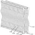
하나 이상의 실시예들에 따르면, 공조 시스템들은 흡습제를 공기 흐름에 노출시키는데 이용되는 중공 플레이트 구조들 세트를 포함할 수 있다. 하나 이상의 실시예들에 따르면, 플레이트 구조들은 그들에 대한 파형(wavy) 형상을 갖는다. 중공 파형 플레이트 구조들은 액체 흡습제의 표면 장력이 드레인 채널로 액체 흡습제를 인출하는데 이용되는 방식으로 구성된다. 하나 이상의 추가 실시예들에 따르면, 멤브레인 또는 습윤 재료와 같은 시트 재료는 액체 흡습제를 드레인 채널로 안내하기 위해 파형 플레이트들 상에 배열될 수 있다. 멤브레인은 전형적으로 사이즈가 0.01 ㎛에서 1 ㎛까지의 범위에 있는 다공들을 갖는 미세 다공 멤브레인일 수 있다. 그러한 멤브레인의 예는 타입 명칭 EZ2090 하에 노스캐롤라이나주 샬럿의 Celgard 및 division of Polypore Corporation에 의해 제조된 멤브레인이다.According to one or more embodiments, air conditioning systems can include a set of hollow plate structures that are used to expose the absorbent to the air stream. According to one or more embodiments, the plate structures have a wavy shape for them. Hollow corrugated plate structures are constructed in such a way that the surface tension of the liquid absorbent is used to draw the liquid absorbent into the drain channel. According to one or more further embodiments, a sheet material, such as a membrane or wetting material, may be arranged on the corrugated plates to guide the liquid absorbent into the drain channel. The membrane may typically be a microporous membrane having pores in size ranging from 0.01 μm to 1 μm. An example of such a membrane is a membrane manufactured by Celgard and division of Polypore Corporation, Charlotte, NC, under the type designation EZ2090.
하나 이상의 실시예들에 따르면, 멤브레인은 액체를 균일하게 분포시키도록 의도된 재료에 의해 뒷받침되는 미세 다공 멤브레인이다. 실시예들에 있어서, 멤브레인은 소수성 미세 다공 멤브레인이다. 실시예들에 있어서, 백킹(backing) 재료는 심지(wicking)재와 같은 친수성 재료이다. 그러한 심지재의 예는 뉴욕주 뉴욕시의 Pellon Company에 의해 제조된 심재(interfacing material)이다.According to one or more embodiments, the membrane is a microporous membrane backed by a material intended to distribute the liquid uniformly. In embodiments, the membrane is a hydrophobic microporous membrane. In embodiments, the backing material is a hydrophilic material, such as a wicking material. An example of such a wick is an interfacing material manufactured by the Pellon Company of New York City, NY.
하나 이상의 실시예들에 따르면, 파형 플레이트 구조들은 공조 시스템에 배열되어 액체 흡습제는 공기 흐름을 실질적으로 방해하지 않고 수직 공기 흐름에 노출된다.According to one or more embodiments, the corrugated plate structures are arranged in an air conditioning system such that the liquid absorbent is exposed to the vertical air flow without substantially disturbing the air flow.
하나 이상의 실시예들에 따르면, 다수의 파형 플레이트 구조 세트들은 흡습제의 건조 또는 습윤 용량이 추가 파형 플레이트들을 간단히 추가함으로써 용이하게 확장될 수 있는 확장 가능한 특성을 갖는 적층 구조로 배열될 수 있다.According to one or more embodiments, a plurality of corrugated plate structure sets can be arranged in a laminated structure with scalable properties in which the dry or wet capacity of the absorbent can be easily expanded by simply adding additional corrugated plates.
하나 이상의 실시예들에 따르면, 멤브레인 흡습제 시스템은 수직 공기 흐름 시스템에서 액체들 및 공기의 역류를 이용하는 공조 시스템을 위해 제공된다.According to one or more embodiments, a membrane sorbent system is provided for an air conditioning system that uses a backflow of liquids and air in a vertical air flow system.
하나 이상의 실시예들에 따르면, 멤브레인 또는 다른 소수성 재료가 멤브레인 뒤에 액체의 적절한 분포를 제공하는 방식으로 습윤 또는 다른 친수성 재료에 접합되는 멤브레인 흡습제 시스템이 제공된다. 실시예들에 있어서, 이중 층은 플라스틱 냉각 채널 또는 지지 플레이트와 같은 (열 전도성) 소수성 구조에 접합된다.According to one or more embodiments, a membrane sorbent system is provided in which a membrane or other hydrophobic material is bonded to a wet or other hydrophilic material in a manner that provides a proper distribution of liquid behind the membrane. In embodiments, the bilayer is bonded to a (thermally conductive) hydrophobic structure, such as a plastic cooling channel or support plate.
하나 이상의 실시예들에 따르면, 플레이트 구성은 플레이트 상부에 액체 흡습제를 확산시키고 플레이트의 하부에 그러한 흡습제를 수집하는 것을 가능하게 한다.According to one or more embodiments, the plate configuration makes it possible to diffuse the liquid absorbent on top of the plate and to collect such absorbent on the bottom of the plate.
하나 이상의 실시예들에 따르면, 파형 플레이트들의 수직 공기 흐름 흡습제 세트로 가는 공기 흐름이 예열되고, 플레이트 구조들 세트를 떠나는 공기가 후 냉각된다.According to one or more embodiments, the air flow to the vertical air flow absorbent set of corrugated plates is preheated, and the air leaving the set of plate structures is then cooled.
하나 이상의 실시예들에 따르면, 플레이트 구조들은 플레이트들이 열을 열적으로 전도할 수 있는 방식으로 구성 및 조립되지만, 열 전도성 플라스틱 재료를 이용하기 때문에 여전히 내부식성이다. 실시예들에 있어서, 그러한 플라스틱은 약 5 내지 10 W/mK의 열 전도성을 갖는다. 예로서 표준 플라스틱들에 대한 열 전도성들은 0.1 내지 0.5 W/mK의 범위인 반면에, 구리, 알루미늄, 스테인레스강 및 티탄은 약 400, 250, 16 및 18 W/mK의 전도성을 각각 갖는다. 이 재료들 중에서 티탄만이 흡습제들의 부식 특성으로 인해 CaCl2 또는 LiCl2와 같은 흡습제와의 이용에 상당히 적절하다.According to one or more embodiments, the plate structures are constructed and assembled in such a way that they can thermally conduct heat, but are still corrosion resistant because they use a thermally conductive plastic material. In embodiments, such plastics have a thermal conductivity of about 5 to 10 W / mK. By way of example thermal conductivity for standard plastics ranges from 0.1 to 0.5 W / mK, while copper, aluminum, stainless steel and titanium have conductivity of about 400, 250, 16 and 18 W / mK, respectively. Of these materials, only titanium is quite suitable for use with an absorbent such as CaCl2 or LiCl2 due to the corrosion properties of the absorbents.
하나 이상의 실시예들에 따르면, 플레이트 구조들은 파형 플레이트들이 서로 평행하게 뿐만 아니라 서로의 상부에도 적층될 수 있는 방식으로 수직으로뿐만 아니라 수직으로 적층될 수 있는 헤더를 이용하여 조립된다.According to one or more embodiments, the plate structures are assembled using a header that can be stacked vertically as well as vertically in such a way that the corrugated plates can be stacked not only parallel to each other but also on top of each other.
하나 이상의 실시예들에 따르면, 플레이트 구조들은 파형 플레이트의 하부에서 액체 흡습제를 헤더로 안내하기 위해 멤브레인 각 플레이트 상에 장착되는 방식으로 조립된다.According to one or more embodiments, the plate structures are assembled in such a way that they are mounted on each membrane plate to guide the liquid absorbent to the header at the bottom of the corrugated plate.
하나 이상의 실시예들에 따르면, 플레이트 구조들에 대한 공기 입구는 파형 플레이트들에 진입하는 공기에서 난류 공기 이동을 생성하는 방식으로 메쉬 또는 차단 플레이트 세트에 의해 차단된다.According to one or more embodiments, the air inlet to the plate structures is blocked by a mesh or barrier plate set in a manner that creates turbulent air movement in the air entering the corrugated plates.
하나 이상의 실시예들에 따르면, 태양광 인버터는 공조 시스템에 대한 전기 연결부들이 태양광 모듈들 세트를 위한 빌딩에 전기적 연결을 제공하는 방식으로 공조 시스템에 통합된다. 일부 실시예들에 있어서, 공조 유닛은 흡습제를 이용한 공조 시스템이다. 일부 실시예들에 있어서, 흡습제를 이용한 공조 시스템은 수직 공기 흐름들을 이용한다. 일부 실시예들에 있어서, 태양광 모듈들은 PVT 모듈들이다.According to one or more embodiments, the solar inverter is integrated into the air conditioning system in such a way that the electrical connections to the air conditioning system provide electrical connection to the building for the set of solar modules. In some embodiments, the air conditioning unit is an air conditioning system using a hygroscopic agent. In some embodiments, the air conditioning system using the absorbent uses vertical air flows. In some embodiments, solar modules are PVT modules.
하나 이상의 실시예들에 따르면, 액체 흡습제를 이용한 수직 공기 흐름 시스템은 냉수 소스로서의 냉각기 및 온수 소스로서의 가스 온수기를 이용하며, 가스 온수기는 태양광 모듈들에 의해 발생되는 열에 의해 보충된다.According to one or more embodiments, a vertical air flow system using a liquid absorbent uses a cooler as a cold water source and a gas water heater as a hot water source, where the gas water heater is supplemented by heat generated by the solar modules.
하나 이상의 실시예들에 따르면, PVT 모듈은 흡습제를 이용한 공조 시스템에 전력 및 열을 제공하고 물 저장 탱크에 열을 제공한다. 온수는 PVT 모듈들 아래의 탱크들에 점차 저장될 수 있고, 전력은 공조 시스템을 작동시키는데 이용될 수 있다. 임의의 초과 전력은 다른 장치들에 제공될 수 있다.In accordance with one or more embodiments, the PVT module provides power and heat to the air conditioning system using the absorbent and heat to the water storage tank. Hot water can be stored gradually in tanks under PVT modules, and power can be used to operate the air conditioning system. Any excess power may be provided to other devices.
하나 이상의 실시예들에 따르면, PVT 모듈들은 밤 동안 열을 방사하는 방식으로 설치되고, 따라서 물의 냉각을 제공한다. 그렇게 냉각된 물은 그것이 낮 동안 흡습제를 이용한 공조 시스템의 콜드 측에 이용가능해질 수 있도록 물 저장 탱크들에 저장될 수 있다. 일부 실시예들에 있어서, 그러한 냉수는 PVT 모듈들과 조합하여 증발기를 이용하여 밤에 발생될 수도 있다.According to one or more embodiments, PVT modules are installed in a manner that radiates heat during the night, thus providing cooling of the water. The water so cooled can be stored in water storage tanks so that it can be made available to the cold side of the air conditioning system with a moisture absorbent during the day. In some embodiments, such cold water may be generated at night using an evaporator in combination with PVT modules.
하나 이상의 실시예들에 따르면, PVT 모듈은 탱크에 진입하거나 매니폴드에 직접 흐르게 하기 위해 자동 온도 조절 스위치에 의해 조정되는 온수를 발생시킨다. 일부 실시예들에 있어서, 자동 온도 조절 스위치는 온수의 온도에 의해 구동된다. 일부 실시예들에 있어서, 스위치는 원격 제어에 의해 작동된다.According to one or more embodiments, the PVT module generates hot water regulated by a thermostat switch to enter the tank or flow directly to the manifold. In some embodiments, the thermostatic switch is driven by the temperature of the hot water. In some embodiments, the switch is operated by remote control.
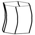
하나 이상의 실시예들에 따르면, 물은 탱크가 PVT 모듈을 위해 밸러스트 및 지지 시스템으로서 기능하기 위해 적절히 균일하게 분포된 중량을 제공하는 방식으로 PVT 모듈 아래의 탱크에 저장된다. 일부 실시예들에 있어서, 탱크는 제거가 가능한 리드를 가진다. 일부 실시예들에 있어서, 탱크는 또한 모듈용 운송 컨테이너로서 기능할 수 있다.According to one or more embodiments, water is stored in the tank below the PVT module in such a way that the tank provides a properly uniformly distributed weight for the ballast and support system for the PVT module. In some embodiments, the tank has a lid that can be removed. In some embodiments, the tank can also function as a shipping container for the module.
하나 이상의 실시예들에 있어서, PVT 모듈들은 플레이트 구조 흡습제 시스템에 연결된다. 일부 실시예들에 있어서, 파형 플레이트 시스템은 빌딩에 차가운 공기를 제공하기 위해 설치된다. 일부 실시예들에 있어서, 파형 플레이트 시스템은 빌딩 공간에 따뜻한 습한 공기를 제공하기 위해 설치된다.In one or more embodiments, PVT modules are connected to a plate structured absorbent system. In some embodiments, the corrugated plate system is installed to provide cold air to the building. In some embodiments, the corrugated plate system is installed to provide warm humid air to the building space.
하나 이상의 실시예들에 따르면, PVT 모듈들은 빌딩 공간에 예정된 공기 가습기로 들어가게 되어 있는 물을 예열하기 위해 연결된다.According to one or more embodiments, PVT modules are connected to preheat water that is intended to enter a predetermined air humidifier in a building space.
하나 이상의 실시예들에 따르면, 흡습제는 용기(vessel) 내의 각종 층들로 분리되며, 여기서 흡습제의 농축은 용기의 높이에 따른다. 일부 실시예들에 있어서, 용기는 흡습제를 이용한 공조 시스템에 흡습제를 제공하고 수집하는데 이용된다. 일부 실시예들에 있어서, 용기의 출구들 중 적어도 하나는 상이한 흡습제 농축들을 갖는 상이한 층들이 용기로부터 선택적으로 인출될 수 있도록 조정가능하다.According to one or more embodiments, the absorbent is separated into various layers in the vessel, where the concentration of the absorbent depends on the height of the vessel. In some embodiments, the container is used to provide and collect the absorbent in an air conditioning system using the absorbent. In some embodiments, at least one of the outlets of the vessel is adjustable such that different layers with different humectant concentrations can be selectively withdrawn from the vessel.
하나 이상의 실시예들에 따르면, 습도가 감소되는 방식으로 플레이트 컨디셔너에 의해 처리되는 공기 흐름의 일부는 수증기의 증발을 통해 공기의 냉각을 제공하는 추가 플레이트들 세트로 우회한다. 일부 실시예들에 있어서, 그러한 시스템은 플레이트들의 표면 상에 멤브레인들을 이용한다. 일부 실시예들에 있어서, 제 2 플레이트들 세트를 가로지르는 공기 흐름은 전환될 수 있고 증발을 위한 물은 겨울철에 작동하는 동안 그것이 빌딩에 진입하는 공기의 추가 가열 용량을 제공하는 방식으로 흡습제에 의해 대체된다.According to one or more embodiments, the portion of the air flow treated by the plate conditioner in a way that reduces humidity bypasses the additional set of plates that provide cooling of the air through evaporation of water vapor. In some embodiments, such a system utilizes membranes on the surface of the plates. In some embodiments, the air flow across the second set of plates may be diverted and the water for evaporation may be diverted by the absorbent in such a way that it provides an additional heating capacity of air entering the building while operating in winter. Replaced.
하나 이상의 실시예들에 따르면, 플레이트 구조들 세트는 증발 냉각 효과를 제공하고 그렇게 생성된 냉각 액체는 컨디셔너뿐만 아니라 하나 이상의 액체 대 공기 열교환기들에도 지향된다. 실시예들에 있어서, 그러한 액체 대 공기 열교환기들은 천장 패널들이다. 실시예들에 있어서, 그러한 액체 대 공기 열교환기들은 팬 코일들이다. 실시예들에 있어서, 그러한 팬 코일들은 덕트 배관 내부에 위치된다. 실시예들에 있어서, 그러한 액체 대 공기 열교환기들은 바닥 아래에 배치된다.According to one or more embodiments, the set of plate structures provides an evaporative cooling effect and the resulting cooling liquid is directed to the conditioner as well as to one or more liquid to air heat exchangers. In embodiments, such liquid to air heat exchangers are ceiling panels. In embodiments, such liquid to air heat exchangers are fan coils. In embodiments, such fan coils are located inside the duct tubing. In embodiments, such liquid to air heat exchangers are disposed below the floor.
하나 이상의 실시예들에 따르면, 일련의 구멍들은 진공 로크(vacuum lock)를 억제하기 위해 및 플레이트 구조를 커버하는 멤브레인 뒤로부터 흡습제의 용이한 배수를 가능하게 하기 위해 멤브레인의 상부에 제공된다.According to one or more embodiments, a series of holes are provided on top of the membrane to suppress vacuum lock and to allow easy draining of the absorbent from behind the membrane covering the plate structure.
하나 이상의 실시예들에 따르면, 플레이트 구조는 구멍들을 비대칭 패턴 상에 제공함으로써 상기 플레이트들의 표면 상의 물 및 액체 흡습제에 번갈아 접근하는 방식으로 구성된다.According to one or more embodiments, the plate structure is constructed in a manner of alternating access to water and liquid absorbents on the surface of the plates by providing holes on an asymmetrical pattern.
하나 이상의 실시예들에 따르면, 열교환기는 부식성 유체들 사이에 열 전달을 제공하기 위해 열 전도성 플라스틱 플레이트들을 이용하여 구성된다. 일부 실시예들에 있어서, 그러한 플레이트 열교환기는 수평 및 수직 역류들을 이용한다. 일부 실시예들에 있어서, 열 전도성 플레이트들은 열 교환을 증진하는 리지(ridge)들 및 특징들을 갖는 방식으로 형성되고 그들이 적층 및 밀봉될 수 있도록 구성된다. 일부 실시예들에 있어서, 열 전도성 플라스틱 플레이트들은 형성되는 것이 아니라, 오히려 접착 재료는 플라스틱 플레이트들의 상부 및/또는 하부에 리지들을 생성 및 부착하는데 이용된다. 일부 실시예들에 있어서, 접착 재료는 또한 플레이트들 사이에서 액체들에 시일을 제공하는데 이용된다. 실시예들에 있어서, 접착제 리지들은 하단 플레이트 상의 리지들이 상단 플레이트의 상부에서 리지들을 지지하고 있는 방식으로 형성되는 한편, 시일 접착제는 2개의 플레이트들 사이에서 틈 전체를 연결한다. 실시예들에서 있어서, 접착제 재료는 미네소타주 세인트 폴의 3M Corporation에 의해 제조된 Marine 5200이다.According to one or more embodiments, the heat exchanger is constructed using thermally conductive plastic plates to provide heat transfer between corrosive fluids. In some embodiments, such a plate heat exchanger uses horizontal and vertical backflows. In some embodiments, the thermally conductive plates are formed in a manner with ridges and features that promote heat exchange and are configured such that they can be stacked and sealed. In some embodiments, thermally conductive plastic plates are not formed, but rather an adhesive material is used to create and attach ridges on top and / or bottom of the plastic plates. In some embodiments, the adhesive material is also used to provide a seal to the liquids between the plates. In embodiments, the adhesive ridges are formed in such a way that the ridges on the bottom plate support the ridges at the top of the top plate, while the seal adhesive connects the entire gap between the two plates. In embodiments, the adhesive material is Marine 5200 manufactured by 3M Corporation of St. Paul, Minnesota.
하나 이상의 실시예들에 따르면, 제 1 플레이트 구조들 세트는 기밀하게 밀봉된 컨테이너 내에 포함되고 제 2 플레이트들 세트는 컨테이너의 대향 측 상에 포함된다. 제 1 플레이트들 세트는 그의 표면 또는 습윤 재료에 걸쳐서 선택적 멤브레인을 포함한다. 제 1 플레이트들 세트는 흡습제 소스로부터 희석된 흡습제를 수용한다. 제 1 플레이트들 세트는 또한 소스로부터 가열된 열 전달 유체를 수용한다. 팬은 수증기가 제 1 플레이트들 세트로부터 취해지는 방식으로 기밀하게 밀봉된 컨테이너 내부에 공기 이동을 제공한다. 제 2 플레이트들 세트는 그의 표면들 상에 물의 응축을 야기시키는 방식으로 공기 환경 및 인클로저에 비해서 비교적 냉각된다. 물은 밀봉된 인클로저로부터 회수될 수 있다. 일부 실시예들에 있어서, 제 2 플레이트들 세트는 외부 콜드 소스에 의해 냉각된다.According to one or more embodiments, the first set of plate structures is included in a hermetically sealed container and the second set of plates is included on the opposite side of the container. The first set of plates includes an optional membrane over its surface or wet material. The first set of plates contains the absorbent diluted from the absorbent source. The first set of plates also contains a heated heat transfer fluid from the source. The fan provides air movement inside the hermetically sealed container in such a way that water vapor is taken from the first set of plates. The second set of plates is relatively cooled compared to the air environment and the enclosure in a manner that causes condensation of water on its surfaces. Water can be recovered from the sealed enclosure. In some embodiments, the second set of plates is cooled by an external cold source.
하나 이상의 실시예들에 따르면, 액체 흡습제가 표면에 노출된 플레이트 구조들 세트는 공기 스트림으로부터 습기를 수집하고 희석된 흡습제를 기밀하게 밀봉된 컨테이너로 지향시키며, 여기서 흡습제가 재생되고 수증기는 액체 물의 형태로 회수된다. 일부 실시예들에 있어서, 시스템에 대한 가열은 태양열 모듈들에 의해 제공된다. 일부 실시예들에 있어서, 시스템에 대한 가열은 PVT 모듈들에 의해 제공된다.According to one or more embodiments, the set of plate structures with the liquid absorbent exposed to the surface collects moisture from the air stream and directs the diluted absorbent to the hermetically sealed container, where the absorbent is regenerated and water vapor is in the form of liquid water. Is recovered. In some embodiments, heating to the system is provided by solar modules. In some embodiments, heating to the system is provided by PVT modules.
하나 이상의 실시예들에 따르면, 액체 흡습제는 먼저 기밀하게 밀봉된 컨테이너에서 재생되고 그 후에 플레이트 구조들의 개방 어레이에서 재생된다. 일부 실시예들에 있어서, 기밀하게 밀봉된 컨테이너에서 회수된 물은 플레이트 구조들 세트로 우회하여 증발 냉각 효과를 제공한다.According to one or more embodiments, the liquid absorbent is first recycled in a hermetically sealed container and then in an open array of plate structures. In some embodiments, water recovered in the hermetically sealed container is diverted to a set of plate structures to provide an evaporative cooling effect.
하나 이상의 실시예들에 따르면, 연료 연소는 배출 가스들이 그의 표면들 상에 액체 흡습제를 갖는 플레이트 구조들 세트를 통해 지향되는 방식으로 발생한다. 배출 가스들은 이산화탄소, 수증기 및 오염물질들 예컨대 SOx 및 NOx와 같은 물질들을 포함하며, 이는 흡습제로 포획될 수 있다. 일부 실시예들에 있어서, 흡습제는 농축된 흡습제 및 액체 물로 재생된다. 일부 실시예들에 있어서, 흡습제는 SOx 및 NOx에 의해 생성되는 산성 및 연료 연소 프로세스로부터 흡수되는 다른 가스들을 제거하는 방식으로 필터링된다.According to one or more embodiments, fuel combustion occurs in such a way that the exhaust gases are directed through a set of plate structures having a liquid absorbent on their surfaces. Exhaust gases include materials such as carbon dioxide, water vapor and contaminants such as SOx and NOx , which can be trapped with an absorbent. In some embodiments, the absorbent is regenerated with concentrated absorbent and liquid water. In some embodiments, the desiccant is filtered in such a way as to remove other gases absorbed from the acidic and fuel combustion processes produced by SOx and NOx .
하나 이상의 실시예들에 따르면, 흡습제는 해수와 같은 수원(water source)으로부터 멤브레인을 통해서 물을 인출한다. 농축된 흡습제는 그러한 멤브레인을 통한 물의 전이의 결과로서 희석된다. 희석된 흡습제는 기밀하게 밀봉된 인클로저로 수송되며, 여기서 흡습제는 농축된 흡습제 및 액체 물이 생성되는 방식으로 재생된다. 일부 실시예들에 있어서, 재생에 대한 가열은 태양열 모듈들에 의해 제공된다. 일부 실시예들에 있어서, 재생에 대한 가열은 PVT 모듈들에 의해 제공된다.According to one or more embodiments, the desiccant draws water through the membrane from a water source such as seawater. The concentrated absorbent is diluted as a result of the transfer of water through such membranes. The diluted absorbent is transported in a hermetically sealed enclosure, where the absorbent is regenerated in such a way that a concentrated absorbent and liquid water are produced. In some embodiments, heating for regeneration is provided by solar modules. In some embodiments, heating for regeneration is provided by PVT modules.
많은 구성 변화들은 그 자체의 장점들 및 단점들을 각각 갖는 상술된 각종 요소들을 조합하는 것으로 상정(想定)될 수 있다. 본 발명은 어떤 방식으로도 그러한 요소들의 특정 세트 또는 조합에 제한되지 않는다.Many configuration changes can be assumed to combine the various elements described above each having its own advantages and disadvantages. The present invention is in no way limited to any particular set or combination of such elements.
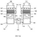
도 1a는 종래 기술에 따라 샤워 헤드 설계를 이용하는 흡습제를 이용한 공조 시스템을 예시한다.
도 1b는 종래 기술에 따라 플레이트 설계 및 수평 공기 흐름을 이용하는 흡습제를 이용한 공조 시스템을 예시한다.
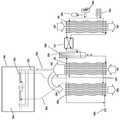
도 2a는 하나 이상의 실시예들에 따라 콜드 소스(cold source) 및 PV/열 모듈 결합을 갖는 혹서기 작동을 위한 흡습제를 이용한 공조 시스템 설치를 도시한다.
도 2b는 하나 이상의 실시예들에 따라 콜드 소스 및 PV/열 모듈 결합을 갖는 비 혹서기 작동을 위한 흡습제를 이용한 공조 시스템 설치를 도시한다.
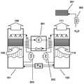
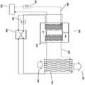
도 3a는 하나 이상의 실시예들에 따라 콜드 소스 및 PV/열 모듈 결합을 갖는 혹한기 작동을 위한 흡습제를 이용한 공조 시스템 설치를 도시한다.
도 3b는 하나 이상의 실시예들에 따라 콜드 소스 및 PV/열 모듈 결합을 갖는 비 혹한기 작동을 위한 흡습제를 이용한 공조 시스템 설치를 도시한다.
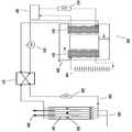
도 4는 하나 이상의 실시예들에 따라 빌딩의 기존 공조 시스템, 흡습제를 이용한 공조 시스템 및 PVT 모듈들 사이에서 통합을 도시한다.
도 5는 하나 이상의 실시예들에 따라 수직 공기 흐름을 이용하는 흡습제 시스템을 도시한다.
도 6a는 하나 이상의 실시예들에 따라 도 5의 시스템의 3차원도를 도시한다.
도 6b는 플레이트 구조들 세트에 진입하는 공기에서 난기류를 생성하는 하나 이상의 난류 플레이트들을 도시한다.
도 7은 하나 이상의 실시예들에 따라 선택적 선 및 후 공기 처리 코일들 및 히트 펌프 시스템을 갖는 수직 공기 흐름 흡습제 시스템을 도시한다.
도 8은 하나 이상의 실시예들에 따라 파형 플레이트 구조들 주위의 상세를 도시한다.
도 9는 하나 이상의 실시예들에 따라 파형 플레이트 구조들에 대한 가능한 구성을 도시한다.
도 10a는 하나 이상의 실시예들에 따라 멤브레인 또는 심지재의 장착을 포함하는 파형 플레이트 구조 어셈블리에 대한 대안 방법을 도시한다.
도 10b는 하나 이상의 실시예들에 따라 친수성 심지재가 2개의 소수성 멤브레인들 사이에 배치된 상태에서 2개의 멤브레인들의 단면을 도시하며, 여기서 심지재는 2개의 멤브레인들 사이에서 액체를 균일하게 확산시킨다.
도 10c는 하나 이상의 실시예들에 따라 소수성 멤브레인, 친수성 심지재 및 (열 전도성) 지지 벽의 단면을 도시한다.
도 10d는 하나 이상의 실시예들에 따라 2개의 심지재 및 내부(열 전도성) 지지 벽과 2개의 멤브레인들의 단면을 도시한다.
도 10e은 하나 이상의 실시예들에 따라 2개의 심지재들 및 내부 중공(열 전도성) 지지 벽과 2개의 멤브레인들의 단면을 도시한다.
도 11a는 하나 이상의 실시예들에 따라 플레이트 구조들이 더 큰 배열로 적층될 수 있는지를 도시하고 구성 상세를 도시한다.
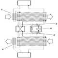
도 11b는 하나 이상의 실시예들에 따라 2개의 컨디셔너들을 통해 수평 공기 흐름을 이용하는 흡습제 시스템을 예시하며, 여기서 공기는 공기 흐름에 대하여 경사를 이루는 플레이트들에 의해 2회 처리된다.
도 11c는 도 11b의 실시예의 평면도를 도시한다.
도 11d는 하나 이상의 실시예들에 따라 공간으로의 유입 공기를 처리하고 제 2 컨디셔너들 세트에서 복귀 공기로부터 에너지를 회수하는 그러한 방식으로 2회 반복된 도 11b의 배치를 도시한다.
도 11e는 하나 이상의 실시예들에 따라 간접 증발 냉각을 위해 제습 공기의 일부를 이용하는 종래 기술에서의 흡습제 멤브레인 플레이트 적층 구조를 도시한다.
도 11f는 간접 증발 냉각을 제어가능 방식으로 제공하기 위해 제습 공기의 일부를 이용하는 흡습제 멤브레인 플레이트 적층 구조의 단면을 예시한다.
도 11g는 도 11f에서의 플레이트 적층 구조의 하부에 대한 클로즈업 부분 절개 상세를 도시한다.
도 11h는 도 11f에 도시된 구성요소들 중 일부의 추가 상세를 예시한다.
도 11i 및 도 11j는 하나 이상의 실시예들에 따라 동시 가열 또는 냉각 기능들을 제공하는 동안 공기 스트림들에 액체 흡습제를 노출시키기 위한 튜브 구조를 이용하는 실시예의 3차원도 및 평면도를 각각 도시한다.
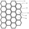
도 11k 및 도 11l은 하나 이상의 실시예들에 따라 가열 또는 냉각 기능들을 제공하는 동안 공기 스트림에 액체 흡습제를 노출시키기 위한 6각형 구조의 3차원도 및 평면도를 각각 예시한다.
도 12는 하나 이상의 실시예들에 따라 태양광 PV/열 어레이를 포함하는 완전한 태양광 공조 시스템을 도시한다.
도 13a는 하나 이상의 실시예들에 따라 저장 및 PVT 모듈들이 낮 동안 흡습제를 이용한 공조 시스템에 대한 온/냉 상쇄(offset) 사이클을 생성하는데 이용될 수 있는지를 증명한다.
도 13b는 하나 이상의 실시예들에 따라 저장 및 PVT 모듈들이 밤 동안 흡습제를 이용한 공조 시스템에 대한 온/냉 상쇄 사이클을 생성하는데 이용될 수 있는지를 증명한다.
도 14a 및 도 14b는 하나 이상의 실시예들에 따라 PV/열 모듈과 통합된 온수 저장/밸러스팅 시스템을 도시한다.
도 15a 및 도 15b는 하나 이상의 실시예들에 따라 밸러스트 탱크 및 저장 시스템이 PVT 모듈을 위한 운송 컨테이너로서 겸용될 수 있는지를 도시한다.
도 16a 및 도 16b는 하나 이상의 실시예들에 따라 PVT 모듈들 및 콜드 소스들이 하절기 작동을 위해 파형 플레이트 흡습제 시스템으로 통합될 수 있는지를 증명한다.
도 17a 및 도 17b는 하나 이상의 실시예들에 따라 PVT 모듈들이 동절기 작동을 위해 파형 플레이트 흡습제 시스템 및 가습기들로 통합될 수 있는지를 증명한다.
도 18a 및 도 18b는 하나 이상의 실시예들에 따라 저장 또는 PVT 모듈들로부터의 열이 공조 작동을 위해 낮 동안 및 밤 동안 이용될 수 있는지를 도시한다.
도 19a는 하나 이상의 실시예들에 따라 흡습제 농축 분리기 및 증발기가 하절기에 작동하는 동안 파형 플레이트 시스템으로 통합될 수 있는지를 도시한다.
도 19b는 빌딩 공간에 통합된 도 19a의 시스템을 도시하며, 여기서 증발기에 의해 생성되는 냉각수는 컨디셔너를 냉각시키는데 이용될뿐만 아니라 천장 패널들 또는 바닥 패널들을 냉각시키는데에도 이용된다.
도 20a는 하나 이상의 실시예들에 따라 도 19a에서의 추가 파형 플레이트들이 동절기에 작동하는 동안 가열 용량을 증가시키는데 이용될 수 있는지를 도시한다.
도 20b는 컨디셔너에 진입하는 공기의 일부가 동절기에 작동하는 동안 컨디셔너로부터 인출되어 제 3 파형 플레이트들 세트로 우회할 수 있는지를 도시한다.
도 21a는 하나 이상의 실시예들에 따라 열 전도성 플라스틱 플레이트들을 갖는 내부식성 열교환기를 도시한다.
도 21b는 하나 이상의 실시예들에 따라 열 전도성 플라스틱 플레이트들을 갖는 내부식성 열교환기의 상이한 실시예를 도시한다.
도 21c는 하나 이상의 실시예들에 따라 유체 열교환기에 유체를 구성하기 위해 접착제 구조들을 이용할 시에 수반되는 주요 제조 단계들을 도시한다.
도 22는 하나 이상의 실시예들에 따라 플레이트 구조들을 이용하는 물 회수 시스템을 도시한다.
도 23은 하나 이상의 실시예들에 따라 가열 및 제습을 위한 흡습제 시스템을 도시한다.
도 24a는 하나 이상의 실시예들에 따라 파형 플레이트들 및 물 회수 시스템을 이용하는 가열 및 제습 시스템을 도시한다.
도 24b는 간접 증발 냉각을 위해 회수된 액체 물을 이용하는 이중 효율 흡습제 재생 시스템을 도시한다.
도 25는 하나 이상의 실시예들에 따라 연소 가스들을 포획 및 응축하고 물을 회수하는 흡습제를 이용한 공조 시스템을 도시한다.
도 26은 하나 이상의 실시예들에 따라 또한 수증기를 응축하고 연소 프로세스로부터 오염물질들을 포획하는 겨울 난방을 위한 흡습제를 이용한 공조 시스템을 도시한다.
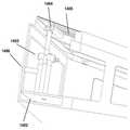
도 27a 및 도 27b는 하나 이상의 실시예들에 따라 도 24a의 시스템의 3차원 모델을 도시한다.
도 28은 하나 이상의 실시예들에 따라 정수를 위해 담수 처리 시스템에 통합되는 도 22의 물 회수 시스템을 도시한다.
유사한 참조 문자들은 일반적으로 도면들에서 동일한 부분들을 나타낸다.1A illustrates an air conditioning system using an absorbent using a shower head design according to the prior art.
1B illustrates an air conditioning system with an absorbent using plate design and horizontal air flow in accordance with the prior art.
FIG. 2A illustrates an air conditioning system installation using an absorbent for cold season operation with a cold source and PV / thermal module combination in accordance with one or more embodiments.
FIG. 2B illustrates an air conditioning system installation using an absorbent for non-heater operation with a cold source and PV / thermal module combination in accordance with one or more embodiments.
FIG. 3A illustrates an air conditioning system installation using a moisture absorbent for cold weather operation with a cold source and PV / thermal module combination in accordance with one or more embodiments.
FIG. 3B illustrates an air conditioning system installation using an absorbent for cold weather operation with a cold source and PV / thermal module combination in accordance with one or more embodiments.
4 illustrates integration between an existing air conditioning system of a building, an air conditioning system with an absorbent and PVT modules in accordance with one or more embodiments.
5 illustrates an absorbent system utilizing vertical air flow in accordance with one or more embodiments.
6A illustrates a three-dimensional view of the system of FIG. 5 in accordance with one or more embodiments.
6B shows one or more turbulent plates that create turbulence in the air entering the set of plate structures.
FIG. 7 illustrates a vertical air flow absorbent system with optional pre and post air treatment coils and a heat pump system in accordance with one or more embodiments.
8 illustrates details around waveform plate structures in accordance with one or more embodiments.
9 shows a possible configuration for waveform plate structures in accordance with one or more embodiments.
10A illustrates an alternative method for corrugated plate structural assembly that includes mounting a membrane or wick in accordance with one or more embodiments.
FIG. 10B shows a cross section of two membranes with a hydrophilic wick disposed between two hydrophobic membranes in accordance with one or more embodiments, wherein the wick spreads liquid evenly between the two membranes.
10C shows a cross section of a hydrophobic membrane, a hydrophilic wick and a (thermally conductive) support wall in accordance with one or more embodiments.
10D shows a cross section of two wicks and an inner (thermally conductive) support wall and two membranes in accordance with one or more embodiments.
10E shows a cross section of two wicks and an inner hollow (thermally conductive) support wall and two membranes in accordance with one or more embodiments.
11A shows if the plate structures can be stacked in a larger arrangement and shows configuration details in accordance with one or more embodiments.
11B illustrates an absorbent system that uses horizontal air flow through two conditioners in accordance with one or more embodiments, where air is treated twice by plates that are inclined to the air flow.
FIG. 11C shows a top view of the embodiment of FIG. 11B.
FIG. 11D shows the arrangement of FIG. 11B repeated twice in such a way to process the incoming air into the space and recover energy from return air in the second set of conditioners in accordance with one or more embodiments.
FIG. 11E illustrates an absorbent membrane plate stack in the prior art utilizing a portion of dehumidified air for indirect evaporative cooling in accordance with one or more embodiments. FIG.
FIG. 11F illustrates a cross section of an absorbent membrane plate laminate structure utilizing a portion of dehumidified air to provide indirect evaporative cooling in a controllable manner.
FIG. 11G shows a close-up partial cutaway detail for the bottom of the plate stack structure in FIG. 11F.
FIG. 11H illustrates additional details of some of the components shown in FIG. 11F.
11I and 11J show a three-dimensional view and a plan view, respectively, of an embodiment that employs a tube structure for exposing liquid absorbent to air streams while providing simultaneous heating or cooling functions in accordance with one or more embodiments.
11K and 11L illustrate a three-dimensional view and a plan view, respectively, of a hexagonal structure for exposing a liquid absorbent to an air stream while providing heating or cooling functions in accordance with one or more embodiments.
12 illustrates a complete solar air conditioning system including a solar PV / thermal array in accordance with one or more embodiments.
FIG. 13A demonstrates that storage and PVT modules can be used to generate a hot / cold offset cycle for an air conditioning system with a hygroscopic during the day in accordance with one or more embodiments.
FIG. 13B demonstrates that storage and PVT modules can be used to generate a hot / cold offset cycle for an air conditioning system with a humectant during the night in accordance with one or more embodiments.
14A and 14B illustrate a hot water storage / ballasting system integrated with a PV / thermal module in accordance with one or more embodiments.
15A and 15B illustrate whether a ballast tank and storage system can be used as a shipping container for a PVT module in accordance with one or more embodiments.
16A and 16B demonstrate that PVT modules and cold sources can be integrated into a waveform plate absorbent system for summer operation in accordance with one or more embodiments.
17A and 17B demonstrate that PVT modules can be integrated into a corrugated plate absorbent system and humidifier for winter operation in accordance with one or more embodiments.
18A and 18B illustrate whether heat from storage or PVT modules can be used during the day and at night for air conditioning operation in accordance with one or more embodiments.
19A illustrates whether the absorbent thickening separator and the evaporator may be incorporated into a corrugated plate system during operation in summer, in accordance with one or more embodiments.
FIG. 19B shows the system of FIG. 19A integrated into a building space, where the coolant generated by the evaporator is used not only to cool the conditioner but also to cool ceiling panels or floor panels.
FIG. 20A illustrates whether the additional corrugated plates in FIG. 19A can be used to increase heating capacity during winter operation in accordance with one or more embodiments.
20B shows if some of the air entering the conditioner can be withdrawn from the conditioner and bypassed to the third set of waveform plates during winter operation.
21A shows a corrosion resistant heat exchanger with thermally conductive plastic plates in accordance with one or more embodiments.
21B shows a different embodiment of a corrosion resistant heat exchanger with thermally conductive plastic plates in accordance with one or more embodiments.
FIG. 21C illustrates the major manufacturing steps involved in using adhesive structures to construct fluid in a fluid heat exchanger in accordance with one or more embodiments.
22 illustrates a water recovery system using plate structures in accordance with one or more embodiments.
23 illustrates an absorbent system for heating and dehumidification in accordance with one or more embodiments.
24A illustrates a heating and dehumidification system utilizing corrugated plates and a water recovery system in accordance with one or more embodiments.
FIG. 24B shows a dual efficiency sorbent regeneration system using recovered liquid water for indirect evaporative cooling.
FIG. 25 illustrates an air conditioning system using an absorbent to capture and condense combustion gases and recover water according to one or more embodiments.
FIG. 26 illustrates an air conditioning system using an absorbent for winter heating that also condenses water vapor and captures contaminants from the combustion process in accordance with one or more embodiments.
27A and 27B show a three-dimensional model of the system of FIG. 24A in accordance with one or more embodiments.
FIG. 28 illustrates the water recovery system of FIG. 22 integrated into a freshwater treatment system for water purification in accordance with one or more embodiments.
Similar reference characters generally indicate identical parts in the figures.
도 1a는 종래 기술에 알려져 있는 액체 흡습제 공조 시스템을 도시한다. 흡습제 컨디셔너(102)는 배스(104) 내의 액체 흡습제를 포함한다. 액체 흡습제(104)는 컨디셔너(102)로 블로잉되는 옥외 공기(110)로부터 수증기를 끌어당기는 임의의 적절한 용액일 수 있다. 공기는 공기 스트림에 흡습제를 용이하게 유지 및 노출시키는 나선형 표면(convoluted surface)을 통상 포함하는 필터 매체(106)를 통해 이동한다. 흡습제들의 예들은 CaCl2 및 LiCl2를 포함한다. 필터 매체는 셀룰로오스 냉각탑 충전 재료일 수 있다. 물을 흡수한 희석된 흡습제(105)는 필터 매체(106)로부터 흡습제 배스(104)로 떨어진다. 스프레이 헤드(107)는 농축된 흡습제를 필터 매체(106)에 걸쳐서 균일하게 분포시킨다. 제습된 및 냉각된 공기(111)는 빌딩으로 지향된다. 희석된 흡습제(112)의 일부(통상 약 10%)는 열교환기(103)를 통해서 재생기(101)로 보내진다. 대부분의 흡습제(112)는 선택적 콜드 소스(113)를 통해서 컨디셔너(102)의 상부에 있는 스프레이 헤드(107)로 돌아온다. 재생기(101)로 전환되는 흡습제는 선택적 히터(114)에서 가열되어 컨디셔너 측 상의 스프레이 헤드와 유사한 스프레이 헤드(107')로 펌핑된다. 가열된 흡습제는 필터 매체(106') 상에 낙하되고(105') 아래의 흡습제 배스(104')로 떨어진다. 빌딩 또는 옥외 공기(108)로부터의 복귀 공기는 필터 매체를 통해서 보내지고 흡습제로부터 물을 흡수해서 습한 열기(109)는 재생기로부터 소모된다. 초기에 논의된 바와 같이, 이 시스템의 결점은 흡습제로 수증기의 흡수가 냉각되기로 되어 있는 공기를 가열하는 거의 단열 프로세스라는 것이다. 더욱이, 스프레이 헤드는 일부 흡습제가 떠나는 공기 스트림들(111 및 109)로 운반되는 것을 초래할 수 있다. 그리고 마지막으로, 배스들(104 및 104')은 공기 흐름들(110 및 108)이 필터 매체를 통해서 수평 및 수직이 되도록 강요한다. 이것은 나가는 공기(111)가 아래 방향으로 덕트로 보내질 필요가 있고 빌딩으로부터의 복귀 공기(108)가 수평 각도로 덕트로 보내질 필요가 있으므로 빌딩 지붕 상의 설치를 더 복잡하게 한다.1A shows a liquid humectant air conditioning system known in the art. The
도 1b는 종래 기술에 공지되어 있는 대체 시스템이다. 컨디셔너(121)는 수직 플레이트들(118) 세트(중공 내부가 되도록 구성됨) 및 흡습제 수집기(120)를 포함한다. 콜드 소스(113, cold source)로부터의 냉각된 열 전달 유체는 플레이트들(118) 내부로 보내지고 플레이트의 내부에 U 형상 루프(116)를 형성한다. 농축된 흡습제(119)는 플레이트들(118)의 표면을 넘친다. 옥외 공기(110)는 흡습제(119)에 걸쳐서 수평 방향으로 지향된다. 흡습제는 공기로부터 수증기를 흡수하고 플레이트들(118)의 표면 아래의 흡습제 수집기(120)에 합류된다. 희석된 흡습제(121)는 열교환기(103)를 통해서 재생기(122)로 펌핑된다. 재생기는 또한 중공이고 그들 내에 U 형상 채널들(116')을 갖는 플레이트들(117) 세트를 포함한다. 희석된 흡습제(119')는 열 전달 유체 소스(114)에 의해 가열되는 플레이트들(117)의 표면을 통해서 다시 진행된다. 빌딩(108)으로부터의 옥외 공기 또는 복귀 공기는 흡습제(119')로부터 수증기를 흡수하는데 이용된다. 흡습제는 그것이 재생기의 표면 아래로 진행되어 흡습제 수집기(115)로 수집되므로 더 농축된다. 이전 예에서와 같이, 흡습제 시스템 내의 공기 흐름은 주로 수평이 되어 지붕 상의 설치에 이용되는 추가 덕트들이 필요해진다. 수평 공기 흐름은 어떤 덕트 작업도 필요하지 않았기 때문에 바람직했지만, 흡습제 수집기들(115 및 120)은 일반적으로 공기가 수직으로 흐르는 것을 차단한다. 더욱이, U 형상 채널들은 공기, 흡습제, 및 냉각 또는 가열 유체들 사이에서 향류 설계를 불가능하게 해서 컨디셔너 및 재생기 둘 다의 열 효율을 낮춘다. 도 1a 내의 시스템과 비교되는 바와 같이, 도 1b 내의 액체 흡습제 시스템은 낮은 팬 전력 및 낮은 흡습제 펌프 전력을 이용한다.1B is an alternative system known in the art. The
도 2a는 하나 이상의 실시예들에 따라 혹서기의 작동을 위해 및 선택적 히트 펌프(201)와 통합하기 위해 구성된 액체 흡습제 시스템을 도시한다. 컨디셔너(102) 내의 흡습제의 일부는 PVT 모듈 어레이에 결합될 수 있는 열교환기(202)를 통해서 보내진다. 이용되는 전형적인 흡습제 재료들이 금속들에 부식되므로, 열교환기의 이용이 바람직하다. 이것은 또한 히트 펌프(201)의 통합을 복잡하게 하며; 흡습제가 임의의 금속 부분들과 접촉하지 않아야 하므로, 열 전달은 특수 설계된 열교환기를 통해 간접적으로 이루어진다. 도면에서 알 수 있는 바와 같이, 흡습제는 컨디셔너로부터 취해지고, PVT 모듈들(202)에서 또는 히트 펌프(201)에 의해 가열되며 재생기(101)로 스프레이된다. 반대로, 농축된 흡습제는 재생기(101)로부터 취해지고, 선택적 콜드 소스(203)를 통해 또는 히트 펌프(201)의 콜드(cold) 측을 통해 및 컨디셔너로 진행된다.2A illustrates a liquid humectant system configured for operation of a heat sink and to integrate with an
도 2b에서, 유사한 설치가 극심하지는 않은 작동을 위해 도시된다. 주된 차이는 컨디셔너로부터의 흡습제가 냉각되고, 또한 재생기에 수송되기보다는 오히려 컨디셔너 측으로 되돌아간다는 것이다. 흡습제는 단지 열교환기(103)를 통해서 재생기에 전달된다. 유사하게, 재생기 내의 흡습제는 단지 가열되고 컨디셔너로 되돌아가기보다는 오히려 재생기 자체로 되돌아간다.In FIG. 2B a similar installation is shown for operation that is not severe. The main difference is that the absorbent from the conditioner cools down and also returns to the conditioner side rather than being transported to the regenerator. The moisture absorbent is only delivered to the regenerator through the
도 3a 내의 혹한기 작동에서, 열원들(201 및 202)은 그것이 컨디셔너(102)에 수송됨에 따라 현재 액체 흡습제를 가열하고 있다. 겨울 설치에서의 컨디셔너는 수증기 및 열을 유입 공기 스트림(110)에 추가하는데 이용되고 그것이 111에서 빌딩에 진입함에 따라 고온 및 습기를 갖는 공기를 조절하는 것이 주목된다. 다른 PVT 모듈 어레이(302)에 의해 또는 다른 열 에너지 소스에 의해 예열될 수 있는 가습기(301)를 추가하는 것이 또한 가능하다. 가습기(301)로 보내지는 물이 금속들에 부식되지 않으므로, 302에서 열 교환기를 이용하는 것이 본질적으로 필요하지 않으며; 물은 PVT 모듈들에 의해 직접 가열될 수 있다. 빌딩으로부터의 복귀 공기(108)는 일반적으로 옥외 공기(110)보다 온도 및 습도가 높다는 것을 주목할 가치가 더 있다. 이 설치에서의 재생기(101)는 실제로 복귀 공기로부터 열 및 습기를 포획하고 그것을 옥외 공기로 수송해서, 가열 비용들을 훨씬 낮추고 흡습제 시스템은 이 설치에서 엔탈피 회수 시스템으로서 효과적으로 기능하고 있다.In cold weather operation in FIG. 3A, the
도 3b에서, 유사한 설치는 현재 열원들(201 및 202)이 시스템의 측 컨디셔너(102) 상의 흡습제를 직접 가열하는데 현재 이용되는 것을 제외하고, 도 3a에서와 같이 도시된다. 유사하게, 히트 펌프(201)의 콜드 측은 재생기 내의 흡습제로부터 열을 직접 인출할 수 있다.In FIG. 3B, a similar installation is shown as in FIG. 3A, except that
도 3a 및 도 3b 내의 콜드 소스(203)는 대부분의 경우에 시스템이 겨울철에 작동하는 동안 필요하지 않을 것이다. 겨울 모드 내의 흡습제는 희석될 필요가 있을 것이며 이는 소량의 물이 흡습제의 과농축을 방지하기 위해 정기적으로 추가될 필요가 있는 것을 의미하는 것이 또한 주목된다. 이 물은 빌딩으로부터의 복귀 공기에서 나올 수 있지만, 여전히 다른 소스들로부터 보충될 필요가 있을 수 있다.The
도 4는 도 3a로부터의 엔탈피 회수 시스템이 기존 빌딩 공조기 시설로 통합될 수 있는지를 도시한다. 빌딩 공간(401)은 덕트들(402)에 의해 도 3a로부터의 흡습제 시스템에 연결된다. 압축기(403)를 포함하는 기존 공조기 히트 펌프는 팬 코일(405)을 통해서 열을 방출하고 유입 공기는 PVT 모듈들(406) 및 추가 팬 코일에 의해 보충적으로 가열될 수 있다. 압축된 가스는 밸브(407)에서 팽창하고 압축기(403)로 복귀되기 전에 팬 코일(404) 내의 복귀 공기(도 4의 '환기')에 의해 가열된다. 상술된 설치는 열 및 수증기 둘 다를 다시 회수함으로써 공조 시스템 상에서 부하를 상당히 감소시킨다.FIG. 4 shows whether the enthalpy recovery system from FIG. 3A can be integrated into an existing building air conditioning facility. Building
도 5에서, 새로운 타입의 액체 흡습제 시스템이 도시된다. 컨디셔너(501)는 내부 중공인 플레이트 구조들 세트를 포함한다. 선택적으로, 플레이트 구조들은 그들에 적용되는 파형(wavy) 형상을 가질 수 있다. 본 출원에서 이용되는 파형이라는 용어는 사형 또는 파동형을 포함하는 각종 나선형 구조들을 광범위하게 지칭한다. 콜드 열 전달 유체는 콜드 소스(507)에서 발생되어 플레이트들로 진입한다. 514에서의 액체 흡습제 용액은 플레이트들의 외부 표면 상에 보내지고 플레이트들 각각의 외부 표면 아래로 진행된다. 일부 실시예들에 있어서, 액체 흡습제는 공기 스트림(503)에 노출되는 흡습제의 영역을 상당히 증가시키는 심재(wicking) 표면에서 진행된다. 다른 실시예들에 있어서 -이하 더 설명됨- 액체 흡습제는 공기 흐름과 플레이트들의 표면 사이에 위치되는 얇은 멤브레인의 뒤를 진행한다. 옥외 공기(503)는 현재 파형 플레이트들 세트를 통해 블로잉된다. 플레이트들의 표면 상의 액체 흡습제는 공기 흐름에서 수증기를 끌어당기고 플레이트들 내부의 냉각수는 공기 온도가 상승하는 것을 방지하는데 도움이 된다. 플레이트 구조들은 도 1a 및 도 1b에 도시된 바와 같이 각 플레이트의 하부 근방의 흡습제를 수집하는 그러한 방식으로 구성됨으로써 흡습제 수집기 또는 배스(bath)에 대한 요구를 제거한다. 처리된 공기(504)는 현재 임의의 추가 덕트들에 대한 요구 없이 직접 빌딩에 넣어진다. 더욱이, 공기, 열 전달 유체들 및 흡습제의 모든 흐름이 수직이므로, 시스템은 열적으로 더 효율적이다. 플레이트들의 파형 형상은 2개의 주요 장점을 가진다: 파형 형상은 직선 플레이트가 제공되는 것보다 오히려 나선형 경로를 구성하므로 공기는 플레이트들의 표면과 더 용이하게 접촉된다. 그러나 중요하게도, 파형 형상은 플레이트들의 상부 및 하부에서 열 전달 유체들 및 흡습제들을 위한 연결들을 최소 응력을 가하지 않고 플레이트들이 사이드웨이들을 확장시키는 것을 가능하게 한다. 이것은 파형 플레이트들 예를 들어 열적으로 도핑된 폴리머 압출형재와 같은 (열 전도성) 플라스틱 재료로부터 이용되는 흡습제와 융화되는 재료로 구성되어야 하므로 특히 중요하다. 전형적으로 그러한 플라스틱은 약 5 내지 10 W/mK의 열 전도성을 갖는다. 예로서 표준 플라스틱들의 열 전도성들은 0.1 내지 0.5 W/m의 범위에 있는 반면에, 구리, 알루미늄, 스테인레스강 및 티탄은 약 400, 250, 16 및 18 W/mK의 전도성을 각각 갖는다. 이 재료들 중에서 티탄만이 흡습제들의 부식 성질로 인해 CaCl2 또는 LiCl2와 같은 흡습제들과의 이용에 합리적으로 적절하다. 재생기(502) 내의 파형 플레이트들은 흡습제를 재생하기 위해 고온 하에 확장될 것이다. 이것은 어셈블리 상에서 열 응력을 생성할 수 있다. 파형 형상은 플레이트들이 수직 방향으로라기 보다는 오히려 사이드웨이들을 확장시키는 것을 가능하게 함으로써 이 응력들을 감소시키는데 도움이 된다.In FIG. 5, a new type of liquid absorbent system is shown.
액체 흡습제는 511에서의 파형 플레이트들의 하부에서 수집되고 액체 흡습제가 재생기의 파형 플레이트들에 걸쳐 분포되는 지점(515)의 재생기의 상부까지 열교환기(513)를 통해서 수송된다. 복귀 공기 또는 선택적으로 옥외 공기(505)는 재생기 플레이트에 걸쳐서 블로잉되고 수증기는 액체 흡습제로부터 떠나는 공기 스트림(506)으로 수송된다. 선택적 열원(508)는 재생을 위해 구동력을 제공한다. 열원로부터의 열 전달 유체(510)는 컨디셔너 상의 콜드 열 전달 유체와 유사한 재생기의 파형 플레이트들 내부에 놓여질 수 있다. 다시, 액체 흡습제는 또한 재생기 상에 공기가 수직일 수 있도록 수직 팬 또는 배스에 대한 요구 없이 파형 플레이트들(502)의 하부에서 수집된다. 파형 플레이트들은 추가 냉각 또는 가열 용량을 추가하기 위해 용이하게 확장될 수 있고, 이 플레이트들은 더 좋은 열 전달을 제공하며 임의의 배스 또는 수집 팬의 제거는 시스템이 추가 덕트 작업에 대한 요구 없이 개방되는 지붕 상에 직접 장착되는 것을 가능하게 하는 것이 당업자들에게 명백해져야 한다. 선택적 히트 펌프(516)는 도 1a에서 이용된 방법과 유사한 액체 흡습제의 냉각 및 가열을 제공하기 위해 이용될 수 있다. 액체 배스 또는 수집 팬의 부재는 예컨대 "분할" 공조 시스템들로서 공지된 것에 통상 이용되는 시스템 내의 다른 구성요소들로부터의 원격 위치에 컨디셔너(501)의 용이한 설치를 가능하게 할 수도 있는 것이 당업자들에게 명백해질 것이다.The liquid desiccant is collected at the bottom of the corrugated plates at 511 and transported through the
도 5의 시스템은 자동차 또는 다른 차량으로 통합될 수 있는 그러한 방식으로 사이즈가 비교적 작아질 수 있는 것이 당업자들에게 더욱 명백해질 것이다. 그러한 자동차에서, 열원(508)는 잠재적으로 엔진으로부터의 열일 수 있으며 냉각은 펠티에 냉각 시스템에 의해 제공될 수 있다.It will be more apparent to those skilled in the art that the system of FIG. 5 can be relatively small in size in such a way that it can be integrated into an automobile or other vehicle. In such vehicles, the
도 6a에서, 도 5의 시스템은 3차원 투사로 도시된다. 흡습제 유체 펌프들(601)은 컨디셔너와 재생기 사이에 흡습제의 수송을 제공한다. 파형 플레이트들(501 및 502)의 상부에 있는 구멍들(602)은 파형 플레이트들의 표면에 걸쳐서 흡습제의 균일한 분포를 보증한다. 파형 플레이트들(501 및 502)의 하부에 있는 집합체들(603, groves)은 흡습제를 집합체로 축적하기 위해 파형 플레이트들의 플라스틱에 흡습제의 자연스런 표면 접착을 이용함으로써 또는 흡습제를 오목부(groove)로 수집하는데 도움이 되도록 일부 멤브레인 또는 다른 습윤 재료를 이용함으로써 흡습제를 수집한다. 열 전달 유체는 연결들(604, 605, 606 및 607)에서 파형 플레이트들에 연결될 수 있다.In FIG. 6A, the system of FIG. 5 is shown in three-dimensional projection. The absorbent fluid pumps 601 provide for transport of the absorbent between the conditioner and the regenerator.
도 6b는 파형 플레이트들(502) 세트의 흡입 공기(652)가 플레이트들(651) 세트에 의해 교란될 수 있는지를 도시한다. 플레이트들(651)은 파형 플레이트들(502)에 진입하는 공기에 난기류를 주는 그러한 방식으로 구성된다. 최종 난류 공기는 층류 방식으로 파형 플레이트들을 흐르는 공기에 비해서 열 및 습기를 파형 플레이트들의 표면과 더 좋게 교환할 것이다.6B shows whether the
도 7은 재생기에 후 컨디셔너 냉각 코일(702) 및 예열 코일(701)을 추가하고 도 5와 유사한 시스템을 도시한다. 히트 펌프(705)의 대체 구성은 도 5에서와 같이 흡습제를 가열하는 대신에, 열 전달 유체를 열교환기 코일들(703 및 704)로 가열하는 것이다. 열교환기를 갖는 요구의 제거는 내부식성 구성요소들을 이용해서 더 많은 표준 열교환기가 이용되는 것을 가능하게 한다.FIG. 7 adds a post
도 8은 파형 플레이트 어셈블리의 일 실시예의 클로즈업 도면을 도시하며, 여기서 플레이트들의 하부에서의 흡습제 드레인(801)은 오목부(811)로 진행되는 흡습제를 수집한다. 열 전달 유체는 802 및 805에서 플레이트들에 연결된다. 파형 플레이트들(803)의 본체는 양호한 열 전도율뿐만 아니라 내부식성을 나타내는 적절한 재료, 예를 들어 열 전도성 플라스틱 압출형재로 제조될 수 있다. 액체 흡습제는 플레이트들(807)의 상부에 있는 분포 채널(806)로 진입되고 동일한 플레이트들의 상부에 있는 구멍들(810)을 나가고 표면(804)을 넘친다. 열 전달 유체(808)는 파형 플레이트들 내의 개구부들(809) 내부에서 진행한다. 도면으로부터 알 수 있는 바와 같이, 오목부들(811)의 구성은 공기 흐름을 방해하는 것 없이 및 분리 공통 수집 팬에 대한 요구 없이 흡습제가 각 개별 플레이트의 하부에서 수집되는 것을 가능하게 한다. 진입하는 공기 스트림(812) 및 나가는 공기 스트림(813)은 반대일 수 있고 또한 802와 805 사이의 열 전달 유체의 방향은 상향 또는 하향일 수 있는 것이 당업자들에게 명백해져야 한다. 흡습제 자체는 통상 흡습제에 작용하는 중력 때문에 표면 아래로 진행된다.8 shows a close-up view of one embodiment of the corrugated plate assembly, where the
도 9는 그러한 파형 플레이트들의 구성의 일 실시예의 다른 상세를 도시한다. 사출 성형 플라스틱 구성요소인 것이 바람직한 구성요소(901)는 열 전도성 압출형재(902)에 접합된다. 기계 가공, 열성형, 용접과 같은 다른 제조 방법들 및 다른 적절한 방법들이 이용될 수 있는 것이 당업자들에게 명백해져야 한다. 구성요소들의 다른 재료들, 예를 들어 티탄 및 다른 값비싼 재료는 전형적 흡습제 용액들의 부식 성질과 융화되기 위해 적절히 선택될 수 있다. 또한 바람직하게는 사출 성형된 유사한 구성요소(903)는 구성요소(902)의 상부에 접합된다. 흡습제는 입구(905)를 통해 도입되고 구멍들(904)을 통해 일반적으로 균일하게 확산된다. 열 전달 유체는 개구부들(905)을 통해 전달되고 개구부들(907)을 통해 존재한다. 파형 플레이트들의 하부로 진행된 흡습제는 오목부(811)로 액체의 표면 장력을 이용함으로써 수집되고 드레인 출구(906)를 빠져 나간다.9 shows another detail of one embodiment of the configuration of such corrugated plates.
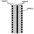
도 10a는 바람직하게는 사출 성형 구성요소들(1001 및 1002)이 파형 플레이트(1003)의 상부에 연결되는 파형 플레이트 구성의 대안 실시예를 도시한다. 스프레더 플레이트들(1013)은 흡습제 및 열 전달 유체가 일반적으로 균일하게 분포되게 한다. 일 실시예에 있어서, 추가 사출 성형 구성요소(1004)는 파형 플레이트(1003) 내부에 열 전달 유체의 수집을 제공한다. 심지재(1005)와 같은 멤브레인 또는 다른 적절한 재료는 어셈블리의 상부에 걸쳐서 도포된다. 그러한 멤브레인의 예는 상표명 EZ2090 하에 Celgard에 의해 제조된 소수성 폴리 프로필렌이다. 심재(wicking) 표면의 예는 커피 여과지와 유사한 친수성 카드보드 시트 재료이다. 완전히 장착된 어셈블리(1007)는 멤브레인 또는 심지재가 흡습제를 구성요소(1006)로 안내하는 그러한 방식으로 최종 사출 성형 구성요소(1006)에 연결된다. 최종 어셈블리(1008)에서, 흡습제(1009 및 1012)에 대한 액체 채널들은 열 전달 유체(1010 및 1011)에 대한 채널들과 같이 도시된다. 재료(1005)가 멤브레인을 포함하면, 파형 플레이트들로부터 액체 흡습제를 드레인하는 것은 어셈블리의 상부가 흡습제를 적소에 "로크"(진공 로크로도 공지됨)할 수 있으므로 새로운 실험이 될 수 있다. 구멍들(1014)은 공기가 멤브레인의 뒤에 진입하는 것을 가능하게 하기 위해 일부로 제공되어 액체 흡습제가 멤브레인의 뒤를 용이하게 충전 및 드레인될 수 있다. 이 구멍들은 또한 멤브레인이 우연히 가압화되는 것을 억제하고, 이 가압화는 멤브레인을 손상 또는 변형시킬 수 있다. 유리하게는, 구멍들은 도 11a에서 더 잘 보여질 수 있는 바와 같이 흡습제의 출구보다 약간 위에 위치된다. 2개의 파형 플레이트 어셈블리들은 플레이트들의 작은 적층 구조를 형성하기 위해 함께 결합된 것이 1008에서 보여질 수도 있다. 파형 플레이트들의 어셈블리는 추가 플레이트들을 적층 구조에 간단히 추가함으로써 공기 처리량을 원하는대로 발생시키도록 적층될 수 있는 것이 당업자에게 명백해져야 한다.10A shows an alternative embodiment of a corrugated plate configuration in which
도 10b는 멤브레인들(1051)과 같은 2개의 소수성 재료들과 친수성 심지재(1052)의 상세한 단면을 도시한다. 미세 다공 멤브레인들 또는 유사한 재료들은 통상 소수성인 것으로 되므로, 멤브레인의 적용은 멤브레인에 의해 반발되는 액체(-예로서- 염 용액 또는 물과 같은)에 의해 야기되는 불균일한 습윤을 가질 수 있다. 반발력들은 멤브레인의 배면 상에서 액체의 흐름을 불균일하게 한다. 친수성 재료(1052)를 이용함으로써, 친수성 재료의 심재 효과는 액체가 멤브레인의 뒤에 균일하게 분포되게 하여 멤브레인을 통해 증발을 상당히 증가시키고 활성 영역을 상당히 증가시킨다. 심지재 내부에 진행되는 액체는 2개의 멤브레인들 사이에서 균일하게 확산될 것이다.10B shows a detailed cross section of a
도 10c는 열 전도성 지지 벽(1053)(예를 들어, 파형 플레이트일 수 있음)에 부착된 멤브레인(1051)과 같은 소수성 재료의 뒤에 친수성 재료(1052)를 도시한다. 지지 벽이 또한 소수성이면 플라스틱들 등에는 그러한 것이 종종 있는 경우이지만, 이 때 심지재는 액체의 균일한 흐름 분포를 보증할 것이다. 지지 벽은 심지재 내에서 액체의 온도를 조정함으로써 멤브레인을 통해 흡수의 증발을 제어하는 것을 가능하게 하는 열 전도성이 될 수 있다.10C shows
도 10d는 심지재가 (열 전도성) 지지 벽(1053)의 양측 상에 도포되는 도 10c와 유사한 구조를 도시한다. 벽의 각 측 상의 습윤 재료들(1052) 내부의 액체들은 현재 상이한 것으로 될 수 있다. 예를 들어, 가장 좌측 심지재는 염 용액으로 습윤될 수 있고 가장 우측 워킹 재료는 물 또는 일부 다른 열 전달 유체로 습윤될 수 있다.FIG. 10D shows a structure similar to FIG. 10C in which the wick is applied on both sides of the (thermally conductive)
도 10e는 지지 벽(1053)이 현재 중공인 것으로 되어 열 전달 액체(1054)가 지지 벽 내부에 이용될 수 있는 도 10d와 유사한 구조를 도시한다. 그러한 구조는 열 전달을 열 전달 유체(1054)로부터 벽들을 통해서 벽(1054)의 어느 한 측 상의 심지재들(1052)로 가능하게 한다. 소수성 및 친수성 재료들의 다른 조합들이 안출될 수 있는 것이 당업자들에게 명백해져야 한다.FIG. 10E illustrates a structure similar to FIG. 10D in which the
도 11a는 파형 플레이트들의 적층 구조과 같은 구성의 추가 상세를 도시한다. 파형 플레이트들(1101)의 적층 구조는 플레이트들을 수직으로뿐만 아니라 수평으로 적층함으로써 공기를 다수 회 처리하기 위해 설치될 수 있다. 수직 적층은 공기가 예를 들어 제습을 증가시키기 위해 처리되는 것을 가능하게 하는 반면, 수평 적층은 처리된 공기의 전체 용량을 증가시킨다. 상세(1102)는 멤브레인 또는 심재 표면(1005)이 흡습제를 하부 드레인(1006)으로 안내하기 위해 이용되는 파형 플레이트 구성의 하부의 상세를 도시한다. 멤브레인 또는 심지재의 하단 가장자리(1111)는 멤브레인 또는 심재 표면의 손상을 초래할 수 있는 흡습제의 잠재적 압력 증진을 회피하기 위해 고정 연결되지 않는다. 상세(1107)는 멤브레인(1005)이 제거된 것을 제외하고 상세(1102)와 동일한 영역을 도시한다. 구성요소들(1004, 1006 및 1003)에서 생성되는 채널들(1109 및 1110)은 멤브레인(1005)이 접합되는 것을 가능하게 하지만, 여전히 흡습제가 채널들을 통과하는 것을 가능하게 한다. 유사하게, 파형 플레이트 어셈블리의 상부의 상세(1103)는 흡습제가 공급 채널(1012)을 통해 진입하고 구성요소들(1002) 내의 채널들을 통해서 및 파형 플레이트 구성요소(1003)의 표면에 걸쳐서 진행될 수 있는지를 도시한다. 구멍들(1014) 및 하부에 있는 비연결된 가장자리(1111)는 1) 어셈블리의 상부에서 베이퍼 로크(vapor lock)를 억제하고 2) 어셈블리의 상부 또는 하부에서의 멤브레인 또는 심재 표면에 압력 손실을 회피하는 기능을 유리하게 하는 것이 상세로부터 명백해져야 한다. 또한, 상세(1108)는 멤브레인(1005)이 제거된 동일한 상부 어셈블리를 도시한다. 파형 플레이트 어셈블리(1101)의 표면적이 시스템의 전체 공기 처리 용량에 중요하므로, 앞서 논의된 바와 같이 수평 및 수직 방향 둘 다로 다수의 파형 플레이트들을 적층하는 것이 용이해져야 한다. 특징들(1104, 1105 및 1106)은 플레이트들을 함께 정렬 및 로킹함으로써 플레이트들의 적층을 가능하게 한다. 그러한 특징들은 많은 형상들 및 사이즈들을 가질 수 있는 것이 당업자들에게 명백해져야 한다.11A shows further details of a configuration, such as a laminated structure of corrugated plates. The stacking structure of the
도 11b는 파형 플레이트들이 수평 공기 흐름을 수락하는 도 5와 유사한 시스템 설치를 도시한다. 도면에서, 파형 플레이트들은 2회 통과하는 공기를 처리하는 그러한 방식으로 2개의 적층 구조를 형성한다. 파형 플레이트들을 입사 공기에 대하여 작은 각도로 배치함으로써, 공기는 파형 플레이트의 표면 상의 액체 흡습제와 더 용이하게 상호작용할 것이다. 그러한 액체 흡습제는 전술된 바와 같이 멤브레인의 뒤에 또는 습윤 재료 내에 위치될 수 있다. 파형 양상을 수직 방향으로 유지함으로써, 파형 플레이트들의 열 팽창 및 수축에 의해 야기되는 임의의 열 응력은 상당히 감소된다.FIG. 11B shows a system installation similar to FIG. 5 in which the corrugated plates accept horizontal air flow. In the figure, the corrugated plates form two laminated structures in such a way as to treat the air passing twice. By placing the corrugated plates at a small angle relative to the incident air, the air will more easily interact with the liquid humectant on the surface of the corrugated plate. Such liquid absorbent may be located behind the membrane or in the wet material as described above. By keeping the wave shape in the vertical direction, any thermal stress caused by thermal expansion and contraction of the wave plates is significantly reduced.
도 11c는 도 11b로부터의 설치를 톱다운 도면으로 예시한다.FIG. 11C illustrates the installation from FIG. 11B in a top down view.
도 11d는 2회 구현된 도 11b로부터의 이중 파형 플레이트들 세트를 도시한다. 제 1 세트는 옥외로부터 들어오는 공기를 처리하고 유입 공기의 이중 처리를 수행한다. 제 2 세트는 공간으로부터의 복귀 공기를 수용하고 또한 그것을 2회 처리한다. 그러한 설치에서, 에너지(수증기 및 열 에너지)의 회수가 거의 완료될 수 있다. 이 설치는 열 에너지가 추가 또는 제거되고 물이 흡습제를 통해 플레이트 시스템에서 나오는 공기에 추가되는 것을 여전히 가능하게 하는 동안 에너지 회수를 가능하게 하고, 그것에 의해 유입 공기의 가열 또는 냉각을 증대시킨다. 종래의 에너지 회수 시스템들은 전형적으로 열 에너지 또는 물의 추가 또는 제거를 불가능하게 한다.FIG. 11D shows the set of dual corrugated plates from FIG. 11B implemented twice. The first set treats incoming air from the outdoors and performs dual processing of the incoming air. The second set receives return air from the space and processes it twice. In such an installation, the recovery of energy (steam and thermal energy) can be nearly complete. This installation enables energy recovery while still allowing heat energy to be added or removed and water to be added to the air exiting the plate system through the absorbent, thereby increasing heating or cooling of the incoming air. Conventional energy recovery systems typically make it impossible to add or remove thermal energy or water.
도 11e는 종래 기술의 흡습제 냉각 시스템을 예시한다. 플레이트들(1134)의 적층 구조가 배치되고(전형적으로 약 0.25 인치 떨어져서) 물(1133)을 그 뒤에 흐르게 하는 멤브레인(1131)에 의해 커버된다. 플레이트의 반대 장소는 액체 흡습제가 흐르는 제 2 멤브레인(1135)을 포함한다. 유입 공기(1136)는 공기 내의 수증기가 멤브레인(1135)을 통해서 액체 흡습제로 흡수되기 때문에 제습된다. 플레이트들의 출구에서, 제습 공기(1137)는 냉각되는 공간을 향해 부분적으로 지향되고 일부는 역 방향(1138)으로 지향된다. 이 2차 공기 흐름(1138)은 비교적 건조되고 물(1132)로부터의 수증기를 멤브레인(1135) 뒤에서 효과적으로 흡수할 수 있다. 멤브레인을 통해서 공기로 수증기의 흡수는 전환된 공기의 냉각 효과를 초래한다. 냉각 공기는 차례로 물(1133)을 냉각시킨다. 그 다음, 냉각수는 플레이트들뿐만 아니라 냉각되는 주요 공기 스트림을 궁극적으로 초래하는 액체 흡습제도 열적으로 냉각시킨다. 이 접근법은 증발 냉각이 플로리다주 마이애미와 같은 기후들에서 발생하는 것을 가능하게 하며, 여기서 습도 레벨들 및 온도들은 냉각탑들이 통상 기능도 하지 않도록 비교적 높다. 우선 유입 공기를 건조시키고 그 후에 멤브레인을 통해서 간접 증발 냉각을 이용함으로써, 시스템은 냉각 효과를 생성하기 위해 증발을 이용할 수 있다. 2차 공기가 옥외 공기와 혼합되는 것을 억제하기 위해, 그것은 도면과 수직인 방향(1140)으로 플레이트 적층 구조의 단부 근방의 다이버터(1139, diverter)에 의해 전환된다. 도면에서 알 수 있는 바와 같이, 멤브레인/액체 층들은 미러링(mirroring)되고 - 물은 물을 향하고 있고 흡습제는 플레이트들 각각에 대한 흡습제를 향할 필요가 있다. 이것은 그러한 플레이트 적층 구조를 제조하기 위한 도전을 야기한다.11E illustrates a prior art hygroscopic cooling system. A layered structure of
도 11f는 도 11e의 개념의 실시예를 예시하며, 여기서 파형 플레이트들(1147)은 액체 흡습제 및 물을 위해 교호 구조를 제공하는데 이용된다. 일부 실시예들에 있어서, 파형 플레이트들은 열 전도성 플라스틱들을 이용하여 제조된다. 파형 플레이트들은 멤브레인들(1131 및 1135)을 지지하기 위해 리지들(1146, ridges)을 포함한다. 액체 흡습제는 채널(1141)을 통해 파형 플레이트 세트에 진입하고 채널(1144)을 통해 존재한다. 물은 채널(1142)을 통해 진입하고 채널(1143)을 통해 나간다. 조정가능하게 연결된 공기 다이버터(1145)는 제어가능한 공기량을 취해서 그것을 역 방향(1138)으로 지향시킨다. 전환된 공기(1138)는 물을 멤브레인(1135) 뒤로부터 흡수한다. 다이버터(1139)는 플레이트들 사이에서 개구부의 상부를 폐쇄하고 공기 흐름(1140)을 수직 방향으로 지향시킨다. 파형 플레이트들(1147)의 하부들 및 상부들은 도 10a의 설계와 유사한 사출 성형 구성요소(1006)로 삽입된다.FIG. 11F illustrates an embodiment of the concept of FIG. 11E, where the
도 11g는 파형 플레이트들 상의 리지들(1146)에 장착된 멤브레인들(1131 및 1135)을 갖는 파형 플레이트들(1147)의 클로즈업인 도 11f의 상세를 도시한다. 파형 플레이트들의 대향 면들에 액체를 제공하기 위해, 구멍들(1150 및 1151)은 파형 플레이트들(1147)의 교호 측들(alternating sides)에 접근할 수 있도록 하는 그러한 방식으로 제공된다. 액체 흡습제는 구멍들(1152)을 통해 드레인 채널(1144)에 진입한다. 도면으로부터 알 수 있는 바와 같이, 파형 플레이트들(1147)은 파형 플레이트들이 교호 방식으로 거꾸로 뒤집혀지는 것을 제외하고, 일반적으로 동일하게 될 수 있다.FIG. 11G shows the detail of FIG. 11F, which is a close-up of
도 11h는 파형 플레이트들(1147)의 상세를 도시한다. 파형 플레이트들은 대안으로 물 및 흡습제 공급 라인들에 반대 연결들을 제공하기 위해 거꾸로 뒤집힌다. 도면에서 알 수 있는 바와 같이, 리지들(1146)은 멤브레인을 위해 지지를 제공하고 열 전도성 표면(1134)은 파형 플레이트의 대향 측에 열 전도성 경로를 제공한다. 구멍들(1153)은 도 10a 내의 구성요소(1013)의 구멍들과 유사한 액체들의 균일한 분포를 제공한다.11H shows details of
본 출원에서 설명된 각종 실시예들에 있어서, 파형 플레이트 구조들은 액체 흡습제를 멤브레인을 통해 공기 스트림에 노출시킴과 동시에 액체 흡습제를 열 전달 유체에 노출시키는데 이용된다. 각종 대체 구조들은 이 기능들을 수행하는데 이용될 수도 있다. 예를 들어, 도 11i 및 도 11j는 액체 흡습제를 멤브레인을 통해 공기 스트림에 노출시킴과 동시에 액체 흡습제를 열 전달 유체에 노출시키기 위한 관형 구조를 예시한다. 구조는 임의의 적절한 열 전도성 재료, 예를 들어 열적으로 도핑된 폴리머 압출형재로 제조될 수 있는 복수의 튜브들(1181)을 포함한다. 튜브의 내부 벽은 액체 흡습제가 그렇게 생성된 채널(1183)에서 도면의 평면과 수직인 멤브레인과 벽 사이를 통과할 수 있도록 멤브레인이 튜브에 대해 짧은 거리에서 유지되는 그러한 방식으로 멤브레인(1182)이 리지들의 상부에 접합되는 것을 가능하게 하기 위해 리지들(1184)의 특징을 이룰 수 있다. 따라서, 공기는 튜브들(1186)의 중심에서 통과될 수 있는 한편, 열 전달 액체는 튜브들 사이에서 전체적으로 삼각형부들(1185)을 통과할 수 있다. 따라서, 열 전달 유체는 열 전도성 벽들을 통해서 흡습제 용액을 가열할 수 있다. 관형 구조들의 다른 형상들 및 배치들이 안출될 수도 있는 것이 이해되어야 한다. 도 11i 및 도 11j는 또한 이전 실시예에서와 같이 구조의 수직 방향으로의 열 팽창으로 인해 응력들을 감소시킴과 동시에 에어와 흡습제 사이에서 더 좋은 상호작용을 달성하는 기능을 하는 튜브에 일부 웨이브 형상을 적용하는 것이 가능하다는 것을 도시한다.In the various embodiments described in this application, corrugated plate structures are used to expose the liquid absorbent to the heat transfer fluid while simultaneously exposing the liquid absorbent to the air stream through the membrane. Various alternative structures may be used to perform these functions. For example, FIGS. 11I and 11J illustrate a tubular structure for exposing the liquid absorbent to the air stream through the membrane while simultaneously exposing the liquid absorbent to the heat transfer fluid. The structure includes a plurality of
도 11l은 하나 이상의 실시예들에 따라 열 전도성 표면들(1192)의 번갈아 형성된 6각형 구조의 평면도이다. 도 11k는 6각형 구조를 형성하는 6각형 요소들 중 하나의 3차원도이다. 구조 내의 각 6각형 요소는 열 전도성 표면들(1192)을 포함한다. 리지들(1194)은 멤브레인들(1191)이 열 전도성 표면들과 실질적으로 평행하게 장착되는 것을 가능하게 한다. 요소들 중 일부에서 멤브레인(1191)과 벽들(1192) 사이의 채널들은 도 11e에 설명된 시스템과 유사한 방식으로 증발 냉각 기능을 수행하기 위해 열 전달 액체의 통과에 이용되거나 차례로 물의 통과에 이용될 수 있다. 도 11l에 도시된 예에서, 회색으로 음영된 멤브레인(1191)과 벽들(1192) 사이에 채널들을 갖는 6각형 요소들은 물을 포함하고, 다른 6각형 요소들 내의 채널들은 액체 흡습제를 포함한다. 따라서, 채널들(1195) 내의 공기는 멤브레인들을 통해서 액체 흡습제에 노출될 수 있는 한편, 이미 처리된 공기(1196)는 멤브레인들을 통해서 물에 노출될 수 있다.11L is a top view of an alternating hexagonal structure of thermally
도 12는 앞서 논의된 파형 플레이트 어셈블리들이 전체 태양광 공조 시스템으로 통합될 수 있는지를 도시한다. 인클로저(1201)는 날씨로부터 흡습제 공기 구성요소들의 보호를 제공한다. 시스템은 컨디셔너(501) 및 재생기(502)를 포함한다. 펌프들(601)은 컨디셔너 및 재생기에 흡습제 흐름을 제공한다. 블로어들(1209)은 공기를 빌딩으로 및 빌딩으로부터 이동시킨다. 옥외 공기(503)는 파형 플레이트들에 의해 처리되고 처리된 공기(504)로서 빌딩으로 이동된다. 빌딩으로부터의 복귀 공기(505)는 열 및 수증기를 흡수하고 506에서 소모될 수 있다. 작은 선택적 냉각기(1203)는 필요하면 현열 냉각을 제공한다. 태양광 인버터(1202)는 일련의 태양광 모듈들(1205)로부터 오는 전기를 반전시킬 수 있다. 태양광 인버터를 공조 시스템(그것이 종래의 공조기이든지 흡습제를 이용한 공조기이든지)에 통합하기 위한 중요한 장점이 있다: 지붕 공조 유닛은 그것에 이르는 상당한 전기 공급 라인을 이미 갖는다. 인버터를 교체 공조 유닛으로 통합함으로써, PV 또는 PVT 모듈들의 설치가 현저히 단순화된다. 통상 태양광 인버터는 빌딩 내의 어딘가에 배치되고 전기 라인들은 지붕에서 상당량의 비용 및 노동을 생성하는 인버터까지 이어진다. 공조기 내에 태양광 인버터를 배치함으로써, 빌딩에 전력을 공급하기 위해 공조기의 기존 전기 라인들이 인버터에 의해 백피드되므로, 임의의 전기 케이블링을 빌딩으로 넣을 필요는 없다. 또한, PV-열 모듈들이 적절한 온도들 또는 전력을 제공할 때 이용될 수 있는 보충수 히터(1204)가 도면에 도시되어 있다. 게다가, 태양광 모듈들(1205)은 접근 온수가 용이하게 저장될 수 있는 그러한 방식으로 물 저장 탱크(1206)를 가질 수 있다. 이 시스템에서, 온수 탱크(1206)는 PVT 모듈에 밸러스트를 제공하는 기능을 한다. 통상 콘크리트 블록 또는 유사한 밸러스트는 평평한 지붕 상에서 태양광 모듈들을 유지하기 위해 제공될 것이다. 그러나, 1206과 같은 얇은 평평한 탱크를 이용함으로써, 2개의 목적을 달성한다: 온수 저장뿐만 아니라 밸러스트. 각 태양광 모듈은 그 자체의 저장 탱크를 가질 수 있는 것이 더 주목되어야 한다. PVT 모듈들(1205) 아래에 탱크들(1206)을 통합함으로써, 모든 전기 라인들(1207) 및 열 전달 유체 라인들(1208)은 빌딩에 진입하는 임의의 라인들을 필요로 하지 않거나 빌딩 내의 어딘가에 탱크들 또는 인버터들을 설치하지 않고 흡습제 시스템(1200)에 통합할 수 있음으로써 시스템에 대한 설치 시간을 상당히 개선한다.12 shows whether the corrugated plate assemblies discussed above can be integrated into an overall solar air conditioning system.
도 13a는 이전 도면에 도시된 그러한 저장 시스템이 이용될 수 있는지를 예시한다. 낮의 시작(1301)에서, PVT 모듈들(1304)은 태양광 방사(1306)를 수용하기 시작한다. PVT 모듈들 아래의 저장 탱크들(1305)은 일반적으로 냉수(또는 어떤 다른 열 전달 유체)로 채워진다. PVT 모듈들은 태양광 공조 시스템(1200)으로, 특히 재생기(1310)로 지향되는 온수를 발생시키기 시작한다. 현열 냉각이 또한 제공될 필요가 있으므로, 냉수 탱크들 중 하나는 컨디셔너(1309)에 연결된다. 낮이 진행됨에 따라(1302), PVT 모듈들은 탱크들 중 일부를 가득 채우기 시작하는데 이용될 수 있는 초과 온수를 발생시킬 수 있다. 연결(1307 및 1308)은 정확한 수의 탱크들이 공조기(1200)에 연결되는 그러한 방식으로 이루어진다. 낮의 끝(1303)에서, 탱크들 대부분 또는 모두는 온수를 포함할 것이다. 이 온수는 현재 도 13b에 도시된 바와 같이 온수 탱크들을 라인들(1316)을 통해서 재생기에 연결함으로써 저녁 및 밤 동안 재생기를 계속 운전시키는데 이용될 수 있다. PVT 모듈들은 또한 방사(1314)에 의해 열을 발산할 시에 비교적 효율적이므로, PVT 모듈들은 현재 라인들(1315)에 의해 컨디셔너에 직접 연결될 수 있다. 한밤중(1312)에서, PVT 모듈들로부터의 방사는 밤의 끝까지 모든 온수가 이용되고 냉수가 모듈들 아래의 탱크들에 채워지는 그러한 방식으로 냉수를 탱크들에 저장하기 시작하는데 이용될 수 있다. 이것은 사이클이 다시 시작하는 것을 가능하게 한다. 실제로 이 배치는 냉수 및 온수 발생의 낮과 밤을 바꾸는 것이 가능하도록 하여, 이는 도 12 내의 작은 냉각기(1203)와 같은 임의의 현열 냉각 시스템에 대한 요구를 제거할 수 있다.13A illustrates whether such a storage system shown in the previous figures can be used. At the beginning of the
도 14a는 일부 상세 레벨에서 도 12로부터 태양광 PVT 모듈들의 실시예를 도시한다. 실리콘 또는 박막 베이스일 수 있는 PV 라미네이트(1401)는 전력을 발생시킨다. 저장 탱크(1402)는 뜨거운 액체 저장 컨테이너뿐만 아니라 밸러스팅 시스템으로도 겸용이 된다. 도 14b는 시스템의 부분 절개 클로즈업을 도시한다. 라미네이트(1401) 뒤의 일련의 얇은 채널들(1405)은 라미네이트로부터 열을 수집하고 전달 유체를 가열한다. 주된 온수 채널(1404)은 물을 자동 온도 조절 밸브 어셈블리(1403) 아래로 가져온다. 자동 온도 조절 밸브는 온수를 주된 매니폴드(1406)로 또는 저장 탱크(1402)로 직접 지향시킬 수 있다. 자동 온도 조절 밸브는 자동으로 또는 소프트웨어 제어를 통해 작동될 수 있다.14A shows an embodiment of solar PVT modules from FIG. 12 at some level of detail.
도 15a 및 도 15b는 PVT 모듈 아래의 저장 탱크의 다른 이용을 증명한다. 이 경우의 저장 탱크는 제거가능 리드(1501, lid) 및 본체(1502)를 갖는다. PV 라미네이트(1503)의 측면 및 배면 지지부(1504)는 탱크 및 PV 라미네이트에 제거가능하게 연결된다. 리드(1501)를 제거한 후에, 전체 태양광 모듈 및 지지 구조는 탱크 본체 내부에 배치될 수 있으므로 선적하는 동안 태양광 모듈을 보호한다. 운송 컨테이너로서 탱크의 이러한 대체 이용은 예를 들어 원격 군사 기반을 위해 생각될 수 있으므로 태양광 모듈들이 정기적으로 설치 및 분해되어야 할 때 매우 유용할 수 있다. 실제로, 탱크는 현재 운송 컨테이너, 저장 탱크 및 밸러스트 시스템 등 3개의 기능을 제공한다.15A and 15B demonstrate another use of the storage tank under the PVT module. The storage tank in this case has a
도 16a는 혹서기 작동을 위한 흡습제 시스템에 통합된 태양열 공조의 개략적인 설치를 나타낸다. 컨디셔너(501)로부터의 모든 흡습제는 재생기(502)로 보내진다. 플레이트 구조들의 이점은 실질적으로 플레이트 세트들(501 및 502)이 공기, 액체 흡습제 및 열 전달 유체 사이에 3방향 열교환기들이라는 점이다. 이는 PVT 모듈들이 1601에서 열 전달 유체를 직접 가열하거나, 1602에서 열교환기를 통해 흡습제를 가열하는 두 위치에서 결합되게 한다. 유사하게 현열 냉각을 위한 저온 연결들은 각각 흡습제 측면(1604) 상에서 또는 열 전달 유체 측면(1603) 상에서 행해질 수 있다.FIG. 16A shows a schematic installation of solar air conditioning integrated into a moisture absorbent system for cold weather operation. All moisture absorbents from the
도 16b는 비 혹서기 작동의 설치를 도시한다. 앞선 경우와의 주요한 차이점은 흡습제의 일부만이 열교환기(513)를 통해 보내진다는 점이다. 1609 및 1610에서 흡습제의 유동들은 흡습제의 일부만이 재생기로 보내지도록 조정될 수 있다. 앞선 경우에서와 같이, PVT 모듈들은 두 위치에서: 흡습제 측면(1606)에서 및 열 전달 유체 측면(1605)에서 결합될 수 있다. 또한 저온 연결은 각각 흡습제(1608) 또는 열 전달 유체(1607) 상에서 행해질 수 있다. 모든 열원들 및 콜드 소스들은 도면들에서 PVT 모듈들 또는 콜드 소스들과 병렬로 또는 직렬로 동일한 라인들로 결합된 다른 소스에 의해 보충될 수 있다는 것은 당업자에게 명백해질 것이다.16B shows the installation of a non-heater operation. The main difference from the previous case is that only a part of the absorbent is sent through the
도 17a는 극심한 조건에서 겨울 난방을 위한 액체 흡습제 시스템을 도시한다. 출구 공기의 능동 냉각(active cooling)이 필수적이지 않으므로, 콜드 소스들은 도면들로부터 생략된다. 또한 PVT 모듈들은 흡습제 측면(1705) 또는 열 전달 유체 측면(1706) 내부에 결합될 수 있다. 가열된 흡습제도 수증기를 방출하므로 부가적인 물이 흡습제의 고농축 및 흡습제 솔트들의 잠재적인 결정화를 방지하도록 1707에 추가되어야 할 수 있다. 또한 처리된 공기(504)가 PVT 모듈들 또는 다른 열원을 갖는 1704에서 물을 사전 가열함으로써 재차 보다 효과적으로 행해질 수 있는 부가적인 가습(1703)을 요구할 수 있다.17A illustrates a liquid sorbent system for winter heating in extreme conditions. Since active cooling of the outlet air is not essential, cold sources are omitted from the figures. PVT modules may also be coupled inside the
도 17b는 흡습제가 일부만이 1708 및 1709에서 열교환기를 통해 보내지는 비혹한기 조건을 제외하고는 도 17a과 유사한 설치를 도시한다.FIG. 17B shows an installation similar to FIG. 17A except for the harsh air condition where only some of the absorbent is sent through the heat exchanger at 1708 and 1709.
도 18a는 도 13a으로부터 PVT 모듈 어레이가 어떻게 액체 흡습제 시스템에 연결될 수 있는 지를 도시한다. PVT 모듈들(1804)은 열을 수용하고 고온 열 전달 유체는 흡습제 재생기(502)와 고온 저장 시스템(1803) 모두에 보내진다. 저온 측면은 저온 저장 탱크들(1805)로부터 냉수를 인출할 수 있다. 밤에, 도 18b는 재생기가 어떻게 고온 저장 탱크들(1803)로부터 현실적으로 인출하는 지를 도시하는 반면, 컨디셔너는 PVT 모듈들(1804)을 통해 열을 복사하고, 그것은 동일한 탱크에서 저온 저장 탱크들(1805) 내로 냉각수를 제공한다FIG. 18A shows how the PVT module array from FIG. 13A can be connected to the liquid absorbent system.
도 18a 및 도 18b으로부터의 설치는 예를 들어, 캘리포니아의 사막에서 또는 센트럴 밸리에서의 경우와 같이 낮과 밤 온도들 사이에 큰 온도 차이가 존재하는 경우에 최적으로 작용한다. 그러나 다른 기후들에서 온도는 그와 동일하게 차이가 발생하지 않을 수 있고 부가적인 현열 냉각이 여전히 요구될 수 있다. 앞서 설명한 바와 같이 그러한 현열 냉각에는 작은 냉각기 또는 히트 펌프가 제공될 수 있다. 펠티에 냉각 또는 증발 냉각과 같은 다른 냉각 수단이 채용될 수 있다는 것은 당업자에게 명백해질 것이다. 플로리다주 마이애미와 같은 기후에서 증발 냉각은 이미 고 습도 레벨들로 인해 여름에서 만큼 효과적이지 않다.The installation from FIGS. 18A and 18B works best when there is a large temperature difference between day and night temperatures, such as in the desert of California or in the Central Valley, for example. However, in other climates the temperature may not equally vary and additional sensible cooling may still be required. As described above, such sensible cooling may be provided with a small cooler or heat pump. It will be apparent to those skilled in the art that other cooling means such as Peltier cooling or evaporative cooling may be employed. In climates like Miami, Florida, evaporative cooling is already not as effective as in summer due to high humidity levels.
도 19a는 제습 공기(504)의 일부를 이용하여 냉각하기 위한 대안 방법을 도시하고 제 3 플레이트 구조들(1904) 세트로 그것을 지향한다. 전환된 공기 흐름(1903)은 이미 처리되어 습도가 낮다. 흡습제 대신에, 제 3 플레이트 구조들 세트는 그 표면상으로 및 멤브레인 또는 심재 표면 뒤로 진행하는 물을 갖고, 플레이트들(1907)에 대해 내부에 열 전달 유체를 갖는다. 전환된 공기는 파형 플레이트들를 사용하는 증발기로서 공지된 것을 생성하는 실질적으로 파형 플레이트들 사이로 현실적으로 지향된다. 물은 1905에서 제 3 세트의 플레이트 구조들로 공급되고 증발되지 않은 물은 라인(1909)을 통해 플레이트들의 상단으로 복귀된다. 전환된 공기(1903)의 일부는 공기의 양이 가변적인 그러한 방식으로 루버(louver)들 또는 배플(baffle)들 또는 몇몇 다른 적절한 메커니즘과 조정될 수 있다. 공기의 양을 변화시키는 것은 진입하는 공기(504)에 의해 빌딩 내에 달성되는 온도를 조절한다. 도 18b에서와 같이, PVT 모듈들(1807)은 냉각 효과를 강화하도록 밤에 사용될 수 있고 냉수는 탱크들(1805) 내에 저장될 수 있다. 컨디셔너(501)의 아래에 제 3 세트의 플레이트 구조들(1904)(부분적으로)을 위치시키는 것도 가능하다. 이는 전체 적층 구조의 높이를 증가시키지만, 대향 방향으로 공기(504)를 재지향할 필요를 제거한다. 반대로 도면에서 평면의 외부로 및 수평 유동 패턴으로 제 3 파형 플레이트들 세트 내부로 공기(504)를 전환시키는 것도 가능하다. 컨디셔너 플레이트들(501) 아래에 제 3 파형 플레이트들 세트를 위치시키는 것은 도 20a에 도시된 것과 같이 겨울 작동을 위한 공기 흐름을 역으로 하는 것이 불가능한 단점을 갖는다. 그러나, 도면의 평면에 수직하게 외부로 공기(504)의 일부를 인출하고 수평 방식으로 제 3 파형 플레이트들 세트(1904)를 통해 그것을 보내는 것은 또한 제 3 세트의 플레이트들 내의 공기가 도 20b에 도시된 바와 같이 겨울 난방을 위해 사용될 수 있게 한다.19A shows an alternative method for cooling using a portion of dehumidified
제3 플레이트들 세트뿐만 아니라, 도 19a는 흡습제 시스템의 다른 개선을 도시한다. 흡습제 저장 시스템(1902)은 유동률들이 낮고 흡습제가 안정될 충분한 시간을 갖는다면 희석된 흡습제가 농축된 흡습제와 물리적으로 분리된다는 점을 이용한다. 환언하면 방치한다면 탱크(1902) 내에 농도는 최고에서 최저까지 치닫도록 증가하는 경향이 있다. 탱크의 측면들을 따라 적절한 높이들로 흡습제 라인들을 연결함으로서 이러한 효과를 이용할 수 있다. 수직으로 조정 가능한 드레인(1908)을 사용하여 탱크 내에 가변 높이로부터 흡습제를 인출하는 것도 가능하다. 드레인(1908)을 위로 이동시킴으로써, 시스템은 보다 낮은 농도 흡습제를 인출하여 보다 적은 제습에 이른다. 실질적으로 이는 시스템에 빌딩 내에서 습도의 제어능을 제공한다. 드레인(1908)을 낮게하는 것은 빌딩 내의 습도를 감소시키지만 재생을 위해 보다 높은 비용들을 발생시킨다. 실질적으로 이는 시스템에 보충 가열 시스템(1901)을 조정함으로써 공기의 온도를 독립적인 제어를 제공하여 PVT 모듈들(1804)이 충분한 열을 발생시키지 못할 경우에 사용된다.In addition to the third set of plates, FIG. 19A shows another improvement of the absorbent system. The
구체적인 실시예와 관련하여 설명된 각종 특징들 및 요소들(예를 들어, 탱크(1902)와 같은)들은 명시적으로 설명하지 않았지만 다른 실시예들에도 실시될 수 있다는 것이 이해되어야 한다.It is to be understood that the various features and elements described in connection with the specific embodiment (eg, tank 1902) are not explicitly described but may be implemented in other embodiments.
도 19b는 도 19a의 시스템을 도시하고 여기서 또한 컨디셔너(501)로 냉각수를 제공하는 기능을 하는 제 3 파형 플레이트들 세트(1904)는 하나 이상의 천장 패널들(1955), 소위 "냉각된 천장"으로 냉각수(1956)를 현실적으로 제공하고 있다. 이러한 접근법은 제 3 세트의 플레이트들 내에서 생성된 냉각수도 통합된 접근법으로 현열 공간 냉각을 제공하게 한다. 냉각된 그리고 건조된 공기(504) 및 1952는 일련의 덕트들(1953)을 통해 일반적으로 안내되고 빌딩(1951) 내의 공간(1954)으로 운반된다. 이러한 접근법은 플레이트 세트들 내에 플레이트들의 수를 변화시키고 공간 내에 습도에 차례로 영향을 주는 흡습제 농도를 조정함으로써 빌딩들의 용이한 밸런싱을 가능하게 한다. 냉각된 천장 플레이트들 대신에 일련의 팬 코일들 또는 공기 열교환기들에 대한 다른 적절한 액체가 배치될 수 있다는 것이 당업자에게 명백해질 것이다.FIG. 19B shows the system of FIG. 19A, wherein the third set of
도 20a는 도 19a로부터의 시스템을 도시하지만 겨울 난방을 위한 설치이다. 종종 겨울에 가열 용량이 여름의 냉각 용량보다 클 것이 요구되므로, 유입 공기의 가열부의 일부로서 제 3 파형 플레이트들 세트를 사용하는 것이 현실적으로 가능하다. 상기 시스템은 제 3 세트의 플레이트들의 표면 상에 물을 유동시키는 대신에, 공기를 처리하도록 액체 흡습제를 현실적으로 사용하고 있다. 겨울 모드에서 보충 히터(1901)는 사용될 필요가 없고 열이 루프(2001) 내의 열 전달 유체에 인가될 필요도 없다. 대신에 보충 히터(2003)가 컨디셔너 파형 플레이트 세트들(501 및 1904) 내에 열 전달 유체를 가열하도록 사용될 수 있다. 부가적인 프리 히터 코일들(2006)은 진입하는 공기(503 및 1906)를 가열하도록 사용될 수 있다. 재생기(502)로 진입하는 흡습제(2002)는 떠나는 공기(505)로부터 열과 수증기를 픽업하고 있다. 도 17a에서 설명된 바와 같이, 이는 배관(2004)을 통해 흡습제가 컨디셔너들로 이러한 열과 물을 수송하므로 컨디셔너를 위한 가열 요구 조건을 감소시키는 역할을 한다. 배관들(2005)은 제 3 파형 플레이트들 세트에도 도달하도록 흡습제를 현실적으로 연결한다. 종종 겨울 조건들이 가습의 발생을 요구하므로, 부가적인 물이 여름 모드에서 증발 냉각을 위해 사용되는 동일한 시스템(1905)을 통해 또는 부가적인 가습기들(1703)에 의해 추가될 수 있다.FIG. 20A shows the system from FIG. 19A but with installation for winter heating. Since the heating capacity is often required to be larger than the summer cooling capacity in winter, it is practically possible to use the third set of corrugated plates as part of the heating portion of the incoming air. Instead of flowing water on the surface of the third set of plates, the system is using realistic liquid absorbents to treat the air. In the winter mode the
도 20b는 어떻게 공기(2051)가 팬(2053)에 의해 푸싱되는 겨울 난방 중 제 3 플레이트들(1904) 세트를 통해 실질적으로 수직 방향으로 유동되는 지를 도시한다. 여름 중 공기(504)의 냉각은 화살표(2052)를 따라 도면의 평면 외부로 지향되고 도면의 평면 뒤 및 제 3 파형 플레이트들 세트(1904)의 뒤에 실질적으로 위치된 팬(2054)에 의해 실질적으로 수평 유동 방향으로 지향된다. 도 20a에 설명된 접근번보다 우수한 이러한 접근법의 이점은 가역 공기 팬에 대한 필요가 없다는 점이다: 대신에 겨울 팬(2503)이 가열 시즌 중 사용되고 여름 팬(2504)이 냉각 시즌 중 사용된다. 컨디셔너 상의 팬(2505)은 항상 동일한 수직 유동으로 공기를 지향하고 있다. 겨울 가열 용량에서 증가 이외에도 이러한 접근법의 또 다른 이점은 제 3 세트의 플레이트들의 전체 영역이 겨울 및 여름 모두에서 능동적으로 사용된다는 점이다. 도 11e에 설명된 접근법은 1) 겨울 난방 지원을 위해 가역될 수 없고, 2) 유효 영역, 공기가 증발 채널(1138)을 통해 유동하는 방식으로 인해 특히 물 채널들(1138)을 위한 유효 영역이 감소되고, 및 3) 흡습제 채널들(1137)에 대한 증발 채널들(1138)의 비가 고정되어, 아마도 보다 적은 증발 작용을 필요로 하고(현열 냉각) 추가의 제습(잠열 냉각)을 필요로 하는 기후들에 시스템을 적용할 수 있는 유연성을 보다 적게 제공한다는 점과 같은 단점을 갖는다. 제 3 세트의 플레이트들과 증발 채널들을 분리시킴으로써, 유연성은 각종 기후 조건들에 시스템에 대한 적용에 대해 증가된다.20B shows how
도 21a는 하나 이상의 실시예들에 따른 플레이트 열교환기를 도시한다. 공조 시스템들 내에 사용된 흡습제들이 금속들에 대해 일반적으로 부식성을 가지므로, 금속으로써 일반적으로 구성되는 보통의 열교환기는 재료들이 부식 듀티에 대해 구체적으로 선택되지 않는 한 용이하게 사용될 수 없고, 그것은 비용에 대해 일반적으로 부정적인 영향을 준다. 평판 플레이트 구성을 사용함으로써 여기서 전체 유닛들은 플라스틱들로 만들어져, 비용들이 일반적으로 감소될 수 있다. 흡습제는 두 위치들에서 열교환기로 진입하고, 예를 들어, 고온 흡습제는 2101에서 진입하고 저온 흡습제로서 2103에서 배출되고, 저온 흡습제는 2102에서 진입하고 고온 흡습제로서 2104에서 나온다. 하우징(2105)은 열 전도성 표면들(2110)을 갖는 플레이트(2106) 어셈블리를 포함한다. 플레이트들(2106) 내부에 방해물들(2109)은 흡습제를 위한 긴 나선형 경로를 생성한다. 수직 분리기들(2107)은 유체를 위해 긴 나선형 경로를 생성하여 유체가 플레이트들 내부로 대향 방향으로 유동하게 한다. 수직 분리기들(2107) 내의 절결부들(2108, cutouts)은 대향 유체를 상하 및 좌우 방향으로 강제한다. 열 전도성 평판 플라스틱 플레이트들의 다른 구성 접근법들이 열교환기로서 사용될 수 있다는 것이 당업자에게 명백해질 것이다.21A illustrates a plate heat exchanger in accordance with one or more embodiments. Since the absorbents used in air conditioning systems are generally corrosive to metals, a common heat exchanger, which is generally constructed as a metal, cannot be readily used unless the materials are specifically selected for the corrosion duty, which is costly. Generally has a negative effect. By using a flat plate configuration here the whole units are made of plastics, so that costs can generally be reduced. The absorbent enters the heat exchanger at two locations, for example, the hot absorbent enters at 2101 and exits at 2103 as a low temperature absorbent, and the low temperature absorbent enters at 2102 and exits at 2104 as the high temperature absorbent.
도 21b는 열교환기를 위한 열 전도성 플라스틱 플레이트들의 대안 배열을 도시한다. 열교환기(2150)는 형성된 열 전도성 플라스틱 플레이트들(2155 및 2157)의 적층 구조를 포함함다. 저온 액체는 2151로 진입하고 플레이트 어셈블리를 통해 가열되고 2152에서 뜨거운 액체로서 배출된다. 뜨거운 액체는 2153으로 진입하고 2154에서 저온으로 배출된다. 플레이트들의 각각은 평판 플레이트들(2155)이 플레이트들(2155)의 하단 좌측으로부터 상단 우측으로의 유동을 가능하게 하고 홀수의 플레이트들(2157)이 하부 우측으로부터 상단 좌측으로 유동을 가능하게 하는 거울상 시일(2156')을 갖는 방식으로 배향되는 시일(2156)을 포함한다. 난류 리지들(2158, turbulence ridges)은 액체 유체가 입구로부터 출구로 이동하는 경우 상하로 진행하게 함으로써 다음의 채널 내에서 액체와 보다 양호한 열 교환을 행하게 한다. 난류 리지들은 플라스틱 플레이트(2155 및 2157) 내부에 그것들을 형성함으로써, 예를 들어 플라스틱을 열 성형 또는 캐스팅함으로써 그와 같이 생성될 수 있다. 대안으로, 플라스틱들 플레이트들을 형성하는 몰딩 비용이 상당하므로 접착 시스템을 사용하여 플레이트들(2155 및 2157)에 대해 접착 라인들(2158)을 부착하는 것이 가능하다. 그러한 접착 라인들은 간단한 XY 로봇식 접착 시스템에 의해 예를 들어 3M Corporation's Marine 5200 Polyurethane glue를 사용하여 형성될 수 있다. 플레이트들이 적층되는 경우 접착 라인들이 서로 지지하고 시일 라인들이 상단과 하단 플레이트들 사이의 거리를 커버하는 그러한 방식으로 실란트 라인들의 높이가 난류 라인들(2155 및 2157)의 높이의 2배로 만들어지는 점을 제외하고는, 밀봉 라인들(2156 및 2156')도 동일한 접착 시스템을 사용하여 형성될 수 있다.FIG. 21B shows an alternative arrangement of thermally conductive plastic plates for the heat exchanger.
도 21c는 플레이트 구조의 개략적인 단면도이고 도 21b에 도시된 바와 같은 유체 열교환기에 유체를 포함하도록 접착제 구조들을 사용하는 것을 포함하는 예시적인 제조 단계들이다. 도 21c에 도시된 바와 같이, 단계 A에서, 플레이트(2155)는 바람직하게 열 전도성으로 만들어지고, 비부식성 재료가 플레이트의 하나의 측면 상에 사전 설정된 패턴으로 접착 리지들(2158)을 고르게 인가할 수 있는 머신 내에 처음으로 위치된다. 접착 리지들이 경화된(단계 B) 후, 플레이트는 뒤집히고 제 2 세트의 접착 리지들(2158)이 유사하거나 또는 상이한 패턴으로 플레이트(단계 C)의 대향 측면으로 인가된다. 따라서 다수의 유사한 플레이트들은 이러한 방식으로 구성된다. 다수의 플레이트들이 경화된(단계 D) 후, 열교환기의 베이스(2161)는 위치 설정되고 베이스에 대해 밀봉을 위해 의도된 접착 패턴(2156)이 인가된다. 경화되기 전, 제 1 플레이트(2155)는 제 1 플레이트(단계 E)의 하부측에 부착되는 방식으로 시일 상에 위치된다. 이러한 프로세스 단계는 다른 플레이트들(단계 F)과 반복된다. 마지막으로, 상단 플레이트(2162)는 접착 시일(2156')(단계 G)과 함께 배치된다. 이러한 구성 프로세스의 이점은 실질적으로 어떠한 설치 또는 툴링 비용들 없이 상이한 재료들 금속들 뿐만 아니라 플라스틱들을 갖는 열교환기 유닛들을 매우 용이하게 만든다는 점이다. 더욱이, 플레이트들을 간단히 확장하고 접착 기계를 사전 프로그래밍함으로써 열교환기의 크기를 용이하게 변경할 수 있다. 종래의 열교환기들은 형성된 금속 플레이트들을 일반적으로 사용함으로써 모든 사이즈 변경은 금속을 형성하기 위한 새로운 다이를 요구할 수 있다. 이들 열교환기들도 종종 캐스트 우레탄 개스킷을 채용하므로 사이즈를 변경하는 것도 새로운 캐스팅 몰드를 종종 요구한다.FIG. 21C is a schematic cross-sectional view of a plate structure and exemplary manufacturing steps that include using adhesive structures to include fluid in a fluid heat exchanger as shown in FIG. 21B. As shown in FIG. 21C, in step A, the
어떤 상황들에서는 옥외 공기 내에 수증기를 캡춰하고 액체 물로 바꾸는 것, 예를 들어, 식수를 만드는 것이 바람직할 수 있다. 도 22는 두개의 세트들의 파형 플레이트들이 인클로저(2201) 내부에 통합된 배열을 도시한다. 제 1 파형 플레이트 세트(2202)는 앞서와 같이 열원(2211)에 의해 발생된 고온 열 전달 액체를 갖는다. 소스(2203)로부터의 흡습제는 파형 플레이트들(2201)의 표면으로 지향된다. 소스(2203)로부터의 열은 수증기가 파형 플레이트들의 표면 상의 흡습제로부터 전개하게 만든다. 팬(2206)에 의해 플레이트들 사이로 드라이빙된 공기(2205)는 수증기를 흡수하고 시스템의 우측 측면으로 이동된다. 시스템이 완전히 인클로징하여 공기가 탈출할 수 없으므로, 인클로저(2201) 내의 상대적인 습도는 거의 100%에 도달한다. 가열될 때, 습한 공기(2205)는 제 1 파형 플레이트들 세트로부터 배출되고, 포화 상태에 가까워진다. 동일한 공기가 제 2 파형 플레이트들(2207) 세트에 도달할 때, 냉수 루프(2208)는 수증기가 파형 플레이트들(2207)의 표면 상에 응축되게 하고 그 후 2210에서 시스템의 외부로 유동하는 액체 물의 형태로 파형 플레이트들(2207)의 하부에서 수집된다. 냉각된 공기(2204)는 파형 플레이트들(2207)의 하부로 배출되고 제 1 파형 플레이트들(2202) 세트 후방으로 수송되고, 그곳에서 재차 가열되고 그곳에서 흡습제로부터 수증기를 흡수하고, 그것은 처음부터 다시 사이클을 시작한다. 감소된 압력에서 도 22의 시스템을 작동시키도록 진공 펌프(2209)를 추가하는 것이 가능하다. 이는 제 1 파형 플레이트(2202) 세트 상의 흡습제로부터 수증기를 전개시키는 요구된 온도를 낮게 하지만, 시스템을 보다 복잡하게 만들고, 예를 들어 출구(2210)에서 시스템으로부터 응축된 물을 복귀시키고 제 1 파형 플레이트들(2202) 세트 상의 흡습제의 역류를 방지하도록 펌프 메커니즘도 추가해야 한다. 공기 열교환기(2212)로의 선택적 공기가 추가될 수 있지만, 열교환기 내의 응축을 발생시키고, 그것은 회수를 보다 어렵게 한다. 파형 플레이트들(2207) 내의 응축이 파형 플레이트들(2202)와 비교된 바와 같이 상대적으로 냉각된 금속 플레이트들의 세트와 같은 다른 방식으로 수행될 수 있다는 것이 당업자에게 명백해질 것이다. 응축 프로세스 내에서 포함된 흡습제가 존재하지 않으므로, 금속 플레이트들과 같은 임의의 적절한 재료가 응축 구성요소를 위해 사용될 수 있다.In some situations it may be desirable to capture water vapor in outdoor air and convert it to liquid water, for example, to make drinking water. 22 shows an arrangement in which two sets of corrugated plates are integrated inside
도 23은 온실들의 제습을 위한 액체 흡습제를 사용하는 시스템을 도시한다. 컨디셔너들(2322 및 2323)은 도 1a 및 도 1b에도 도시된 바와 같은 액체 흡습제 컨디셔너들를 포함한다. 스프레이 헤드들(2314)는 냉각탑 필터(2315) 내부로 흡습제를 스프레이하고, 그것은 온실 공기(2317)를 제습한다. 희석된 흡습제(2316)는 수집 배스(2318) 내부로 비처럼 흘러내린다. 흡습제(2324)의 일부는 열교환기(2320)를 통해 펌핑되고 재생기(2301)에 이른다. 흡습제는 재생기의 일부인 흡습제 수집기(2304)에 이르기 전 PVT 모듈 열원(2319)에 의해 선택적으로 가열될 수 있다. 수집기(2304) 내에 농축된 흡습제의 일부는 필터 재료(2303) 내부로 스프레이되기 전 열교환기(2306)로 그리고/또는 선택적 PVT 모듈 가열 시스템(2305)을 통해 펌핑된다. 필터 재료(2303)는 공기를 통과시키면서 큰 영역에 걸쳐 흡습제를 확산시킬 수 있다. 공기(2302)는 필터 재료를 통해 팬(2309)에 의해 펌핑되고 고온 흡습제로부터 수증기를 픽업한다. 그 후 고온 습윤 공기는 냉수가 2321에서 공기 내부로 스프레이되는 재생기의 다른 측면으로 수송된다. 물은 공기로부터 응축되고 수집 배스(2310) 내부에서 수집된다. 물의 일부는 물이 컨디셔너들(2322 및 2323)를 통해 들어오는 공기 스트림에 의해 냉각되는 열교환기들(2313)로 배관들(2312)을 통해 펌핑된다. 과잉의 물은 2311에서 드레인된다. 시스템을 위한 열은 물 히터(2308)에 의해 또는 PVT 모듈들(2307)에 의해 선택적으로 제공된다. 열교환기(2306)는 흡습제로 인한 부식 때문에 물 히터에 의한 직접 가열을 허용하지 않으므로 필요하게 된다.FIG. 23 shows a system using a liquid absorbent for dehumidification of greenhouses.
도 24a는 현저하게 보다 효과적인 물 발생 시스템을 도시한다. 파형 플레이트 컨디셔너(2405)는 진입하는 공기(2406)를 처리하고 파형 플레이트들의 표면 상으로 진행하는 흡습제 내에서 앞서와 같이 습기를 흡수한다. 떠나는 공기(2407)는 진입하는 공기(2406)보다 따뜻하고 건조하다. 희석된 흡습제는 열교환기(2404)를 통해 그리고 상기 설명된 물 회수 시스템(2200)으로 선택적 PVT 모듈 히터(2403)를 통해 펌핑된다. 파형 플레이트들이 실질적으로 3방향 열교환기를 포함하므로, 시스템(2400)은 보다 간단화할 수 있다. 물 히터(2402) 및 선택적 PVT 모듈들(2401)은 열교환기에 대한 필요없이 물 회수 시스템(2200) 내부로 파형 플레이트들을 통해 진행하는 열 전달 유체(2409)를 가열한다. 유사하게, 2408에의 냉각 액체는 부가적인 열교환기 없이 컨디셔너 파형 플레이트들(2405)을 통해 직접 진행할 수 있다. 이러한 보다 간단한 시스템도 컨디셔너 내의 공기 흐름이 방해받지 않고 파형 플레이트들 내의 가열 및 냉각이 제 위치에서 행해지므로 보다 에너지 효율적이다. 그 결과 PVT 모듈들과 같은 낮은 온도 열원이 사용될 수 있다. 물은 2410에서 재차 회수된다.24A illustrates a significantly more effective water generation system. The
희석된 액체 흡습제의 재생은 낮은 온도에서 뿐만 아니라 높은 효율로 바람직하게 수행되어야 한다. 다중 효용 재생들은 고효율을 갖는다고 본 기술 분야에 공지되어 있지만, 일반적으로 높은 온도를 요구한다. 높은 재생 온도들은 "폐" 에너지 소스들 또는 태양 에너지 소스들을 사용하는 것을 어렵게 하거나 불가능하게 한다. 일반적으로 보다 낮은 온도의 폐 에너지는 높은 온도 폐 에너지보다 보다 용이하고 보다 값싸게 이용 가능하다. 도 24b는 도 22로부터 물 회수 시스템 및 도 19a의 간접 냉각 시스템의 조합을 도시한다. 재생기 플레이트(502) 세트 내부에 물 회수 시스템(2200)을 조합함으로써, 흡습제의 재생은 다중 효용 재생기로서 공지된 것으로 된다. 희석된 흡습제(511)는 물 회수 시스템(2200) 내부에 플레이트들에 처음으로 지향된다. 파형 플레이트들 내부에는 온수(2409)가 액체 흡습제로부터의 액체를 증발시키도록 제공된다. 액체 흡습제는 보다 높은 농도로 물 발생기로 배출되고 515에서 플레이트들로 지향된다. 물 발생기(2200) 내부의 고온 수증기는 재생기의 파형 플레이트들(502)을 차례로 가열하는 물 루프(2408)를 가열한다. 그 후 농축된 흡습제(512)는 컨디셔너 내에서 재사용되도록 열교환기(513)를 통해 복귀된다. 이러한 시스템의 하나의 이점은 여전히 보다 낮은 온도에서 작동하는 한편, 단일한 효능 재생기보다 보다 높은 효율들을 재발생시킬 수 있다는 점이다. 또한 회수된 물(2410)은 도 19a로부터의 간접 냉각 시스템의 증발 섹션으로 물 라인(2451) 및 선택적 냉각기(2452)를 통해 지향됨으로써, 물 공급 소스를 제공할 필요를 감소시키거나 오히려 제거할 수 있다.Regeneration of the diluted liquid humectant should preferably be carried out at low temperatures as well as with high efficiency. Multiple utility regenerations are known in the art to have high efficiency, but generally require high temperatures. High regeneration temperatures make it difficult or impossible to use "waste" energy sources or solar energy sources. Lower temperature waste energy is generally easier and cheaper than higher temperature waste energy. FIG. 24B shows a combination of the water recovery system from FIG. 22 and the indirect cooling system of FIG. 19A. By combining the
도 25는 몇몇 부가적인 개선을 갖는 도 24a의 시스템을 도시한다. 재생기(2200)로 모든 흡습제를 보내는 것보다, 분리기(2501)는 분리기의 상부 근처에 적어도 농축된 흡습제가 재생을 위해 보내지게 하고 대부분의 농축된 흡습제가 컨디셔너 내에서 재차 사용되게 한다. 화석 연료들의 연소는 일반적으로 이사화탄소 및 수증기를 생성하게 한다. 다른 연소 부산물들은 NOx 및 SOx 및 생성물들에 의한 다른 잔여물과 같은 오염물질들이다. 가스 버너(2502)는 온실 내부에서와 같이 처리될 공간 내에서 사용된다면 이러한 가스들을 생성한다. 온수 코일들(2503)은 버너에 의해 발생된 열의 대부분을 흡수한다. 온수는 재생기(2200) 내에서 사용된다. 수증기, C02 및 NOx 및 SOx와 같은 오염물질들은 온수 코일들을 통해 나가고 파형 플레이트들(2405)에 진입한다. C02는 온실 내에서 바람직하지만, 수증기 및 다른 오염물질들은 그렇지 않다. 실질적으로 파형 플레이트들은 연소 배기에서 물을 흡수함으로써 응축된 보일러로서 공지된 것과 같은 기능을 하고, 그것은 부가적인 열을 배출하고 전체 연소 프로세스를 보다 효과적으로 만든다. 그러나 응축 보일러와 달리 흡습제도 버너 폐수들 내에 몇몇 오염물을 흡수할 수 있다. 흡습제는 보충 필터들(2411)이 재생기 내에서 흡습제의 외부로 또는 공기 스트림의 외부로 이들 오염물질들을 필터링하도록 채용될 수 있는 재생기(2200)로 물과 함께 오염물질들을 수송한다. 도 25의 배열은 천연 가스와 같이 클린 버닝을 하지 않는 바이오 가스와 같은 연료의 연소의 버닝을 가능하게 한다. 또한 물의 응축에 도움을 주도록 추가될 수 있는 부가적인 외부 냉각기(2504)가 도면에 도시된다.25 illustrates the system of FIG. 24A with some additional improvements. Rather than sending all the absorbent to regenerator 2200,
도 26은 앞선 도면 내에 설명된 몇몇 개념들이 어떻게 도 17에 설명된 바와 같은 겨울 난방 시스템 내부에 통합될 수도 있는지를 도시한다. 물 히터(2602)는 가스 버너(2601)를 사용한다. 가열된 물(2604)도 컨디셔너(501)를 가열하도록 PVT 모듈들(1706)에 의해 가열될 수 있다. 재생기(501)의 표면 상에 흡습제는 수증기 및 NOx및 SOx 및 생성물들에 의한 다른 잔여물과 같은 다른 오염 물질을 흡수한다. 흡습제는 흡습제 내에 몇몇 오염물질들을 캡춰링할 수 있는 선택적 필터들(2603)을 통해 물 회수 시스템(2200)으로 수송된다. 2608에서 회수된 물은 배출될 수 있거나 또는 라인들(2609)을 통해 가습기(1703)로 전환될 수 있고, 그것은 PVT 모듈들(1704) 또는 몇몇 다른 열원에 의해 선택적으로 사전 가열될 수 있다. 재생기(2200) 내에 물의 응축을 위한 저온 루프는 외부 냉각 코일(2607)에 의해 냉각될 수 있지만, 라인들(2606)에 의해 파형 플레이트들(502)로 물을 진행시킴으로써 냉각될 수도 있다.FIG. 26 shows how some concepts described in the preceding figures may be incorporated into a winter heating system as described in FIG. 17. The
도 27a 및 도 27b는 온실 가열을 위해 설치된 도 24a로부터의 시스템의 흡습제의 3차원도를 도시한다. 도 27a는 흡습제 컨디셔너 파형 플레이트들(2405)를 포함하는 인클로저(2701)를 도시한다. 팬들(2701)은 흡습제 컨디셔너를 통해 공기를 이동시킬 수 있다. 도 27b는 내부 구성요소들을 예시하도록 제공된 몇몇 개구부들을 갖는 동일한 시스템의 후면도를 도시한다. 재생기 플레이트들(2202)은 물 히터(2402)로부터 온수를 수용한다. 열교환기(2404)는 고온 및 저온 흡습제들을 분리한다. 응축기 플레이트들(2207)은 시스템으로부터 물을 수집한다.27A and 27B show three-dimensional views of the absorbent of the system from FIG. 24A installed for greenhouse heating. FIG. 27A shows an
도 28은 물 발생기(2200)가 어떻게 담수 처리 시스템 내에서 사용될 수 있는지를 도시한다. 바다물(2803)은 대향 측면 상에 농축된 흡습제(2804)를 갖는 멤브레인들(2801)의 세트 사이로 안내된다. 흡습제는 흡습제 내부로 멤브레인을 통해 물(2802)을 끌어오는 인출(draw) 유체로서 기능함으로써 흡습제를 희석시킨다. PVT 모듈들(2806)의 선택적인 세트는 몇몇 흡습제를 사전 가열할 수 있다. 희석된 흡습제는 재생기(2200)로 열교환기(2811)를 통해 현실적으로 안내된다. 가열 시스템(2807)은 재생기 파형 플레이트들(2813) 내부에서 사용되는 열 전달 유체를 가열한다. 열 전달 유체도 PVT 모듈들(2812)에 의해 가열될 수 있다. 흡습제도 PVT 모듈들(2810)에 의해 가열될 수 있다. 외부 냉각 루프(2808)가 응축기 플레이트들(2814)를 냉각하도록 채용될 수 있다. 순수 물은 지점(2809)에서 회수된다. 설명된 시스템이 삼투 현상을 사용하는 담수 처리 시스템들보다 현저하게 보다 낮은 동력 레벨들로 작동될 수 있는 것이라면 용액 펌프 전력이 매우 낮게 유지되므로 이점을 갖는다.28 shows how
따라서, 몇몇 예시적인 실시예들을 설명했지만, 각종 대안들, 변형들, 및 개선들이 당업자가 용이하게 실시할 수 있다는 것이 이해될 것이다. 그러한 대안들, 변경들, 및 개선들은 본 개시의 일부를 형성하도록 의도된 것이며, 본 개시의 사상과 범위 내에 있도록 의도된 것이다. 몇몇 예들이 기능들 또는 구조적 요소들의 구체적인 조합들을 포함하도록 본원에서 제공되는 한편, 그들 기능들 및 요소들이 동일한 또는 상이한 목적들을 수행하도록 다른 방법들로 조합될 수 있다는 것이 이해되어야 한다. 구체적으로, 일 실시예와 관련되어 설명된 작용들, 요소들, 및 특징들은 다른 실시예들에서 유사한 또는 다른 역할들로부터 배제되도록 의도되지 않는다. 부가적으로, 본원에 설명된 요소들 및 구성요소들은 부가적인 구성요소들로 더 분할되거나 동일한 기능들을 수행하기 위한 보다 작은 구성요소들을 형성하도록 함께 결합될 수 있다. 따라서, 앞선 설명 및 첨부된 도면들은 예시만을 위한 것이고, 제한으로 의도된 것은 아니다.Thus, while some exemplary embodiments have been described, it will be understood that various alternatives, modifications, and improvements may be readily made by those skilled in the art. Such alternatives, modifications, and improvements are intended to form part of this disclosure, and are intended to be within the spirit and scope of the disclosure. While some examples are provided herein to include specific combinations of functions or structural elements, it should be understood that they may be combined in other ways to perform the same or different purposes. Specifically, the actions, elements, and features described in connection with one embodiment are not intended to be excluded from similar or other roles in other embodiments. In addition, the elements and components described herein may be further divided into additional components or combined together to form smaller components to perform the same functions. Accordingly, the foregoing description and the accompanying drawings are for illustrative purposes only and are not intended to be limiting.
Claims (546)
Translated fromKorean실질적으로 수직 방향으로 배열된 복수의 구조들을 포함하는 컨디셔너로서, 각 구조는 액체 흡습제가 흐를 수 있는 적어도 하나의 표면을 갖고, 상기 공기 스트림은 상기 구조들을 통해서 또는 상기 구조들 사이에서 흘러서 상기 액체 흡습제는 상기 공기 스트림을 제습하고, 각 구조는 상기 구조의 상기 적어도 하나의 표면에 걸쳐서 흐르는 액체 흡습제를 수집하기 위한 흡습제 수집기를 적어도 하나의 표면의 하단부에 더 포함하는 상기 컨디셔너;
상기 컨디셔너에 연결되어 상기 컨디셔너 내의 상기 흡습제 수집기들로부터 액체 흡습제를 수용하고, 실질적으로 수직 방향으로 배열된 복수의 구조들을 포함하는 재생기로서, 각 구조는 상기 액체 흡습제가 흐를 수 있는 적어도 하나의 표면을 갖고, 상기 공기 스트림은 상기 구조들을 통해서 또는 상기 구조들 사이에서 흘러서 상기 액체 흡습제가 물을 탈착(desorb)하게 하고, 각 구조는 상기 구조의 상기 적어도 하나의 표면에 걸쳐서 흐르는 액체 흡습제를 수집하기 위한 흡습제 수집기를 상기 구조의 하단부에 더 포함하고, 상기 재생기에서 상기 액체 흡습제를 가열하는데 이용되는 열 전달 유체를 가열하기 위한 태양광-열(PVT) 모듈을 더 포함하는 상기 재생기;
상기 컨디셔너와 상기 재생기 사이에 연결되어 상기 재생기에서 상기 컨디셔너로 흐르는 상기 액체 흡습제로부터 상기 컨디셔너에서 상기 재생기로 흐르는 상기 액체 흡습제로 열을 전달하기 위한 열교환기; 및
상기 컨디셔너와 재생기 사이에서 상기 액체 흡습제를 순환시키기 위한 장치를 포함하는 흡습제를 이용한 공조 시스템.An air conditioning system using a desiccant for cooling an air stream entering a building space,
A conditioner comprising a plurality of structures arranged in a substantially vertical direction, each structure having at least one surface through which a liquid absorbent can flow, wherein the air stream flows through or between the structures and the liquid absorbent The conditioner further dehumidifying the air stream, each structure further comprising an absorbent collector at the bottom of at least one surface for collecting a liquid absorbent flowing over the at least one surface of the structure;
A regenerator comprising a plurality of structures connected to the conditioner to receive a liquid absorbent from the absorbent collectors in the conditioner and arranged in a substantially vertical direction, each structure having at least one surface through which the liquid absorbent can flow; And the air stream flows through or between the structures such that the liquid absorbent desorbs water, and each structure collects liquid absorbent flowing over the at least one surface of the structure. The regenerator further comprising a humectant collector at the bottom of the structure and further comprising a solar-heat (PVT) module for heating a heat transfer fluid used to heat the liquid humectant in the regenerator;
A heat exchanger coupled between the conditioner and the regenerator for transferring heat from the liquid absorbent flowing from the regenerator to the conditioner to the liquid absorbent flowing from the conditioner to the regenerator; And
And an apparatus for circulating the liquid absorbent between the conditioner and the regenerator.
실질적으로 수직 방향으로 배치된 복수의 구조들을 포함하는 컨디셔너로서, 각 구조는 액체 흡습제가 흐를 수 있는 적어도 하나의 표면을 갖고, 상기 공기 스트림은 상기 구조들을 통해서 또는 상기 구조들 사이에서 흘러서 상기 액체 흡습제는 상기 공기 스트림을 제습하고, 각 구조는 상기 구조의 상기 적어도 하나의 표면에 걸쳐서 흐르는 액체 흡습제를 수집하기 위한 흡습제 수집기를 상기 적어도 하나의 표면의 하단부에 더 포함하고, 상기 액체 흡습제를 가열하는데 이용되는 열 전달 유체를 가열하기 위한 태양광-열(PVT) 모듈을 더 포함하는 상기 컨디셔너;
상기 컨디셔너로부터 액체 흡습제를 수용하고, 상기 액체 흡습제를 제습하고, 상기 액체 흡습제를 상기 컨디셔너로 복귀시키고, 실질적으로 수직 방향으로 배열된 복수의 구조들을 포함하는 재생기로서, 각 구조는 상기 액체 흡습제가 흐를 수 있는 적어도 하나의 표면을 갖고, 상기 공기 스트림은 상기 구조들을 통해서 또는 상기 구조들 사이에서 흘러서 상기 액체 흡습제가 물을 흡수하게 하고, 각 구조는 상기 구조의 상기 적어도 하나의 표면에 걸쳐서 흐르는 액세 흡습제를 수집하기 위한 흡습제 수집기를 상기 구조의 하단부에 포함하는 상기 재생기;
상기 컨디셔너와 상기 재생기 사이에 연결되어 상기 컨디셔너에서 상기 재생기로 흐르는 상기 액체 흡습제로부터 상기 재생기에서 상기 컨디셔너로 흐르는 상기 액체 흡습제로 열을 전달하기 위한 열교환기;
상기 컨디셔너와 재생기 사이에서 상기 액체 흡습제를 순환시키기 위한 장치를 포함하는 흡습제를 이용한 공조 시스템.An air conditioning system using an absorbent for heating an air stream entering a building space,
A conditioner comprising a plurality of structures disposed substantially in a vertical direction, each structure having at least one surface through which a liquid absorbent can flow, wherein the air stream flows through or between the structures and the liquid absorbent Further dehumidifies the air stream, each structure further comprising an absorbent collector at the bottom of the at least one surface for collecting a liquid absorbent that flows over the at least one surface of the structure, and used to heat the liquid absorbent. The conditioner further comprising a solar-heat (PVT) module for heating the heat transfer fluid being;
A regenerator comprising a plurality of structures that receive a liquid absorbent from the conditioner, dehumidify the liquid absorbent, return the liquid absorbent to the conditioner, and are arranged in a substantially vertical direction, each structure being configured to allow the liquid absorbent to flow. Having at least one surface, the air stream flows through or between the structures to allow the liquid absorbent to absorb water, and each structure flows through the at least one surface of the structure; The regenerator comprising an absorbent collector for collecting a lower end of the structure;
A heat exchanger coupled between the conditioner and the regenerator for transferring heat from the liquid absorbent flowing from the conditioner to the regenerator to the liquid absorbent flowing from the regenerator to the conditioner;
And an apparatus for circulating the liquid absorbent between the conditioner and the regenerator.
상기 공기 스트림을 제습하기 위한 액체 흡습제 및 상기 액체 흡습제를 냉각하기 위한 열 전달 유체를 이용하는 컨디셔너;
상기 컨디셔너에 연결되어 상기 컨디셔너로부터 상기 액체 흡습제를 수용하기 위한 재생기로서, 열 전달 유체를 이용하여 상기 액체 흡습제를 가열하고 상기 액체 흡습제가 물을 탈착(desorb)하게 하는 상기 재생기;
상기 흡습제를 이용한 공조 시스템을 작동시키는데 이용되는 전력을 발생시키기 위한 태양광-열(PVT) 모듈로서, 낮 동안 상기 재생기에 이용되는 열 전달 유체를 가열하고 밤에 열 전달 유체로부터 열을 방사함으로써 상기 컨디셔너에 이용되는 열 전달 유체를 냉각하도록 구성된 상기 태양광-열(PVT) 모듈;
상기 PVT 모듈에 의해 가열되는 상기 열 전달 유체를 저장하고 상기 PVT 모듈에 의해 냉각되는 상기 열 전달 유체를 저장하기 위한 하나 이상의 탱크들; 및
상기 컨디셔너와 상기 재생기 사이에 연결되어 상기 재생기에서 상기 컨디셔너로 흐르는 상기 액체 흡습제로부터 상기 컨디셔너에서 상기 재생기로 흐르는 상기 액체 흡습제로 열을 전달하기 위한 열교환기를 포함하며;
상기 재생기는 낮 동안 상기 PVT 모듈에 의해 가열되는 열 전달 유체를 이용하고 밤에 제 1 탱크에 저장된 상기 열 전달 유체를 이용하도록 구성되고,
상기 컨디셔너는 밤에 상기 PVT 모듈에 의해 냉각되는 열 전달 유체를 이용하고 낮 동안 제 2 탱크에 저장된 상기 열 전달 유체를 이용하도록 구성되는 흡습제를 이용한 공조 시스템.An air conditioning system using an absorbent for treating an air stream entering a building space,
A conditioner using a liquid absorbent for dehumidifying the air stream and a heat transfer fluid for cooling the liquid absorbent;
A regenerator connected to the conditioner for receiving the liquid absorbent from the conditioner, the regenerator for heating the liquid absorbent using a heat transfer fluid and allowing the liquid absorbent to desorb water;
A photovoltaic-heat (PVT) module for generating power used to operate an air conditioning system using the hygroscopic agent, comprising: heating the heat transfer fluid used in the regenerator during the day and radiating heat from the heat transfer fluid at night The solar-heat (PVT) module configured to cool the heat transfer fluid used in the conditioner;
One or more tanks for storing the heat transfer fluid heated by the PVT module and for storing the heat transfer fluid cooled by the PVT module; And
A heat exchanger coupled between the conditioner and the regenerator for transferring heat from the liquid absorbent flowing from the regenerator to the conditioner to the liquid absorbent flowing from the conditioner to the regenerator;
The regenerator is configured to use a heat transfer fluid heated by the PVT module during the day and to use the heat transfer fluid stored in the first tank at night,
The conditioner is configured to use a heat transfer fluid cooled by the PVT module at night and to use the heat transfer fluid stored in a second tank during the day.
상기 공기 스트림을 제습하기 위한 액체 흡습제 및 상기 액체 흡습제를 가열하기 위한 열 전달 유체를 이용하는 컨디셔너;
상기 컨디셔너에 연결되어 상기 컨디셔너로부터 상기 액체 흡습제를 수용하기 위한 재생기로서, 상기 액체 흡습제를 제습하고 상기 액체 흡습제를 냉각하기 위한 열 전단 유체를 이용하는 상기 재생기;
상기 흡습제를 이용한 공조 시스템을 작동시키는데 이용되는 전력을 발생시키기 위한 태양광-열(PVT) 모듈로서, 낮 동안 상기 컨디셔너에 이용되는 열 전달 유체를 가열하고 밤에 상기 열 전달 유체로부터 열을 방사함으로써 상기 재생기에 이용되는 열 전달 유체를 냉각하도록 구성된 상기 태양광-열(PVT) 모듈;
상기 PVT 모듈에 의해 상기 열 전달 유체를 저장하고 상기 PVT 모듈에 의해 냉각되는 상기 열 전달 유체를 저장하기 위한 하나 이상의 탱크들; 및
상기 컨디셔너와 상기 재생기 사이에 연결되어 상기 컨디셔너에서 상기 재생기로 흐르는 상기 액체 흡습제로부터 상기 재생기에서 상기 컨디셔너로 흐르는 상기 액체 흡습제로 열을 전달하기 위한 열교환기를 포함하며;
상기 컨디셔너는 낮 동안 상기 PVT 모듈에 의해 가열되는 열 전달 유체를 이용하고 밤에 제 1 탱크에 저장된 상기 열 전달 유체를 이용하도록 구성되고,
상기 재생기는 밤에 상기 PVT 모듈에 의해 냉각되는 열 전달 유체를 이용하고 낮 동안 제 2 탱크에 저장된 상기 열 전달 유체를 이용하도록 구성되는 흡습제를 이용한 공조 시스템.An air conditioning system using an absorbent for treating an air stream entering a building space,
A conditioner using a liquid absorbent for dehumidifying the air stream and a heat transfer fluid for heating the liquid absorbent;
A regenerator connected to the conditioner for receiving the liquid absorbent from the conditioner, the regenerator using a thermal shear fluid to dehumidify the liquid absorbent and cool the liquid absorbent;
A photovoltaic-heat (PVT) module for generating power used to operate an air conditioning system using the hygroscopic agent, by heating a heat transfer fluid used in the conditioner during the day and radiating heat from the heat transfer fluid at night The solar-heat (PVT) module configured to cool the heat transfer fluid used in the regenerator;
One or more tanks for storing the heat transfer fluid by the PVT module and for storing the heat transfer fluid cooled by the PVT module; And
A heat exchanger coupled between the conditioner and the regenerator for transferring heat from the liquid absorbent flowing from the conditioner to the regenerator to the liquid absorbent flowing from the regenerator to the conditioner;
The conditioner is configured to use the heat transfer fluid heated by the PVT module during the day and to use the heat transfer fluid stored in the first tank at night,
And the regenerator is configured to use a heat transfer fluid cooled by the PVT module at night and to use the heat transfer fluid stored in a second tank during the day.
액체 흡습제를 이용하여 따뜻한 날씨 작동 모드에서 상기 공기 스트림을 제습하고 추운 날씨 작동 모드에서 상기 공기 스트림을 가습하기 위한 컨디셔너;
상기 컨디셔너에 연결되어 상기 컨디셔너로부터 상기 액체 흡습제를 수용하기 위한 재생기로서, 상기 액체 흡습제가 상기 따뜻한 날씨 작동 모드에서 물을 탈착(desorb)하게 하고 상기 추운 날씨 작동 모드에서 물을 흡수하게 하는 상기 재생기;
상기 컨디셔너를 통해서 상기 공기 스트림을 이동시키기 위한 장치;
상기 컨디셔너 및 재생기를 통해서 상기 액체 흡습제를 순환시키기 위한 장치; 및
상기 따뜻한 날씨 작동 모드에서 상기 재생기에 도입될 액체 흡습제를 가열하고 상기 추운 날씨 작동 모드에서 상기 컨디셔너에 도입될 액체 흡습제를 가열하기 위한 태양광-열(PVT) 모듈로서, 상기 흡습제를 이용한 공조 시스템을 작동시킬 시에 이용되는 전력을 발생시키기 위한 하나 이상의 태양광 전지들을 또한 포함하는 상기 태양광-열(PVT) 모듈을 포함하는 흡습제를 이용한 공조 시스템.An air conditioning system using an absorbent for treating an air stream entering a building space,
A conditioner for dehumidifying the air stream in a warm weather mode of operation with a liquid desiccant and humidifying the air stream in a cold weather mode of operation;
A regenerator connected to the conditioner to receive the liquid absorbent from the conditioner, the regenerator allowing the liquid absorbent to desorb water in the warm weather mode of operation and to absorb water in the cold weather mode of operation;
An apparatus for moving the air stream through the conditioner;
A device for circulating the liquid absorbent through the conditioner and regenerator; And
A solar-heat (PVT) module for heating a liquid absorbent to be introduced into the regenerator in the warm weather mode of operation and for heating a liquid absorbent to be introduced into the conditioner in the cold weather mode of operation, wherein the air conditioning system using the absorbent is An air-conditioning system using a moisture absorbent comprising the solar-heat (PVT) module also comprising one or more solar cells for generating power used in operation.
환경으로부터 공조 시스템 구성요소들을 보호하기 위한 외부 인클로저; 및
상기 하나 이상의 태양광 전지들에 결합되어 상기 하나 이상의 태양광 전지들에 의해 발생되는 직류 전기를 교류 전기로 반전시키기 위한 태양광 인버터로서, 상기 공조 시스템의 상기 외부 인클로저 내에 위치되는 상기 태양광 인버터를 더 포함하는 흡습제를 이용한 공조 시스템.The method of claim 131, wherein
An external enclosure for protecting the air conditioning system components from the environment; And
A solar inverter coupled to the one or more solar cells for inverting direct current electricity generated by the one or more solar cells into alternating current, the solar inverter being located in the outer enclosure of the air conditioning system. Air conditioning system using a moisture absorbent further comprising.
액체 흡습제를 이용하여 따뜻한 날씨 작동 모드에서 상기 공기 스트림을 제습하고 추운 날씨 작동 모드에서 상기 공기 스트림을 가습함으로써 상기 공기 스트림을 조절하는 단계;
상기 액체 흡습제가 상기 따뜻한 날씨 작동 모드에서 물을 탈착(desorb)하게 하고 상기 액체 흡습제가 상기 추운 날씨 작동 모드에서 물을 흡수하게 함으로써 상기 공기 스트림을 조절할 시에 이용되는 상기 액체 흡습제를 재생하는 단계; 및
태양광-열(PVT) 모듈을 이용하여 상기 따뜻한 날씨 작동 모드에서 재생될 상기 액체 흡습제를 가열하고 상기 추운 날씨 작동 모드에서 상기 공기 스트림을 조절하는데 이용될 상기 액체 흡습제를 가열하는 단계; 및
상기 PVT 모듈을 이용하여 상기 흡습제를 이용한 공조 시스템을 작동시킬 시에 이용되는 전력을 발생시키는 단계를 포함하는 방법.A method for treating an air stream entering a building space,
Conditioning the air stream by dehumidifying the air stream in a warm weather mode of operation with a liquid desiccant and humidifying the air stream in a cold weather mode of operation;
Regenerating the liquid absorbent used in regulating the air stream by causing the liquid absorbent to desorb water in the warm weather mode of operation and allowing the liquid absorbent to absorb water in the cold weather mode of operation; And
Heating the liquid absorbent to be regenerated in the warm weather mode of operation using a solar-heat (PVT) module and heating the liquid absorbent to be used to regulate the air stream in the cold weather mode of operation; And
Generating power for use in operating the air conditioning system using the moisture absorbent using the PVT module.
상기 액체 흡습제를 탱크에 퇴적시키는 단계;
상기 탱크의 높이에 따라 상기 액체 흡습제가 달리 농축되도록 퇴적되는 것을 허용하는 단계; 및
주어진 농축을 갖는 액체 흡습제를 획득하기 위해 상기 탱크의 주어진 선택 높이에서 상기 탱크로부터 상기 공기 스트림을 조절할 시에 이용되는 액체 흡습제를 인출하는 단계를 더 포함하는 방법.The method of claim 148, wherein
Depositing the liquid absorbent in a tank;
Allowing the liquid absorbent to be deposited to be concentrated differently depending on the height of the tank; And
Withdrawing a liquid absorbent used to adjust the air stream from the tank at a given selected height of the tank to obtain a liquid absorbent having a given concentration.
실질적으로 수직 방향으로 배열된 복수의 구조들을 포함하는 컨디셔너로서, 각 구조는 액체 흡습제가 흐를 수 있는 적어도 하나의 표면을 갖고, 상기 공기 스트림은 상기 구조들을 통해서 또는 상기 구조들 사이에서 흘러서 상기 액체 흡습제는 따뜻한 날씨 작동 모드에서 상기 공기 스트림을 제습하고 추운 날씨 작동 모드에서 상기 공기 스트림을 가습하며, 각 구조는 상기 구조의 상기 적어도 하나의 표면에 걸쳐서 흐르는 액체 흡습제를 수집하기 위한 흡습제 수집기를 상기 적어도 하나의 표면의 하단부에 더 포함하는 상기 컨디셔너;
상기 컨디셔너에 연결되어 상기 컨디셔너 내의 상기 흡습제 수집기들로부터 액체 흡습제를 수용하기 위한 재생기로서, 상기 액체 흡습제가 상기 따뜻한 날씨 작동 모드에서 물을 탈착(desorb)하게 하고 상기 추운 날씨 작동 모드에서 물을 흡수하게 하는 상기 재생기;
상기 컨디셔너를 통해서 상기 공기 스트림을 이동시키기 위한 장치; 및
상기 컨디셔너 및 재생기를 통해서 상기 액체 흡습제를 순환시키기 위한 장치를 포함하는 흡습제를 이용한 공조 시스템.An air conditioning system using an absorbent for treating an air stream entering a building space,
A conditioner comprising a plurality of structures arranged in a substantially vertical direction, each structure having at least one surface through which a liquid absorbent can flow, wherein the air stream flows through or between the structures and the liquid absorbent Dehumidifying the air stream in a warm weather mode of operation and humidifying the air stream in a cold weather mode of operation, each structure comprising: an at least one absorbent collector for collecting a liquid sorbent flowing across the at least one surface of the structure The conditioner further comprises a lower end of the surface of the;
A regenerator connected to the conditioner to receive a liquid absorbent from the absorbent collectors in the conditioner, the liquid absorbent causing the liquid desorbent to desorb water in the warm weather mode of operation and to absorb water in the cold weather mode of operation; The regenerator;
An apparatus for moving the air stream through the conditioner; And
And an apparatus for circulating said liquid absorbent through said conditioner and regenerator.
(a) (i) 실질적으로 수직 방향으로 배열되고 상기 공기 스트림의 통과를 위해 구조들 사이에서 또는 구조들을 통해서 흐름 경로들을 정의하는 복수의 구조들로서, 각 구조는 액체 흡습제 또는 물이 흐를 수 있는 적어도 하나의 외부 표면을 가져서 상기 공기 스트림은 일부 흐름 경로들에 있을 때 상기 액체 흡습제에 노출되어 제습되고 다른 흐름 경로들에 있을 때 물에 노출되어 가습되며, 각 구조는 상기 구조의 상기 적어도 하나의 표면에 걸쳐서 흐르는 상기 액체 흡습제 또는 물을 수집하기 위한 수집기를 그 구조의 상기 적어도 하나의 표면의 하단부에 더 포함하는 상기 복수의 구조들; 및
(ii) 제습된 상기 공기 스트림의 일부를, 물의 일부는 흡수되고 냉각되는 물이 노출되는 흐름 경로로 전환하기 위한 하나 이상의 다이버터(diverter)들을 포함하는 상기 컨디셔너;
(b) 상기 컨디셔너에 연결되어 상기 컨디셔너 내의 흡습제 수집기들로부터 액체 흡습제를 수용하기 위한 재생기로서, 상기 액체 흡습제가 물을 탈착(desorb)하게 하고, 상기 액체 흡습제를 상기 컨디셔너로 복귀시키는 상기 재생기;
(c) 상기 컨디셔너를 통해서 상기 공기 스트림을 이동시키기 위한 장치; 및
(d) 상기 컨디셔너 및 재생기를 통해서 상기 액체 흡습제를 순환시키기 위한 장치를 포함하는 흡습제를 이용한 공조 시스템.An air conditioning system using an absorbent for treating an air stream entering a building space,
(a) (i) a plurality of structures arranged in a substantially vertical direction and defining flow paths between or through the structures for passage of the air stream, each structure having at least a liquid absorbent or water flowable therethrough; With one outer surface the air stream is exposed to the liquid desiccant and dehumidified when in some flow paths and humidified by exposure to water when in other flow paths, each structure being the at least one surface of the structure. The plurality of structures further comprising a collector at a lower end of the at least one surface of the structure for collecting the liquid absorbent or water flowing over; And
(ii) said conditioner comprising one or more diverters for diverting a portion of said dehumidified air stream to a flow path where a portion of water is absorbed and the water to be cooled is exposed;
(b) a regenerator connected to the conditioner for receiving a liquid absorbent from the absorbent collectors in the conditioner, the regenerator causing the liquid absorbent to desorb water and returning the liquid absorbent to the conditioner;
(c) a device for moving the air stream through the conditioner; And
and (d) a device for circulating said liquid absorbent through said conditioner and regenerator.
인접한 플레이트들 사이에 채널들을 정의하는 실질적으로 평행한 플레이트들의 적층 구조으로서, 상기 제 1 및 제 2 유체들은 상기 적층 구조의 대체 채널들을 통해서 개별적으로 흐르고, 복수의 실질적으로 평행한 플레이트들은 열 전도성 플라스틱을 포함하는 상기 적층 구조(stack);
상기 제 1 유체가 흐르는 상기 채널들과 유체 연통되는 제 1 유체 입구 포트 및 제 1 유체 출구 포트; 및
상기 제 2 유체가 흐르는 상기 채널들과 유체 연통되는 제 2 유체 입구 포트 및 제 2 유체 출구를 포함하는 열교환기.A heat exchanger for transferring heat between first and second fluids,
A stack structure of substantially parallel plates defining channels between adjacent plates, wherein the first and second fluids flow separately through alternate channels of the stack structure, and the plurality of substantially parallel plates are thermally conductive plastics. The stack including a stack;
A first fluid inlet port and a first fluid outlet port in fluid communication with the channels through which the first fluid flows; And
And a second fluid inlet port and a second fluid outlet in fluid communication with the channels through which the second fluid flows.
(a) 열 전도성 플라스틱을 각각 포함하는 복수의 플레이트들을 제공하는 단계;
(b) 상기 플레이트들 각각 상에 접착제 재료의 패턴을 접합하는 단계; 및
(c) 상기 제 1 유체 및 상기 제 2 유체가 개별적으로 흐를 수 있는 인접한 플레이트들 사이에 채널이 형성되게 상기 플레이트들을 적층(stacking)하는 단계로서, 상기 접착제 재료는 상기 제 1 유체 및 상기 제 2 유체의 흐름을 위한 개별 대체 채널들을 유지하기 위해 및 상기 제 1 유체 및 상기 제 2 유체의 흐름을 전체적으로 횡 방향들로 지향시키기 위해 인접한 플레이트들 사이에 시일(seal)들을 형성하는 상기 적층하는 단계를 포함하는 방법.A method of configuring a heat exchanger for transferring heat between a first fluid and a second fluid,
(a) providing a plurality of plates each comprising a thermally conductive plastic;
(b) bonding a pattern of adhesive material on each of the plates; And
(c) stacking the plates such that a channel is formed between adjacent plates through which the first fluid and the second fluid can flow separately, wherein the adhesive material comprises the first fluid and the second fluid. Forming the seals between adjacent plates to maintain separate replacement channels for the flow of fluid and to direct the flow of the first and second fluids in transverse directions as a whole; How to include.
빌딩 공간에 진입하는 공기 스트림을 처리하기 위한 공조 유닛으로서, 환경으로부터 공조 유닛 구성요소들을 보호하기 위한 외부 인클로저를 포함하는 상기 공조 유닛;
태양 에너지를 직류 전기로 변환하기 위한 하나 이상의 태양광 모듈들; 및
상기 하나 이상의 태양광 모듈들에 결합되어 상기 하나 이상의 태양광 모듈들에 의해 발생되는 상기 직류 전기를 상기 공조 유닛에 전력 공급하기 위한 교류 전기로 반전시키기 위한 태양광 인버터로서, 상기 공조 시스템의 상기 외부 인클로저 내에 위치되는 상기 태양광 인버터를 포함하는 태양광 공조 시스템.As a solar air conditioning system,
An air conditioning unit for treating an air stream entering a building space, the air conditioning unit comprising an external enclosure for protecting air conditioning unit components from an environment;
One or more solar modules for converting solar energy into direct current electricity; And
A solar inverter coupled to the one or more solar modules for inverting the direct current generated by the one or more solar modules into alternating current for powering the air conditioning unit, the external of the air conditioning system A solar air conditioning system comprising the solar inverter located within an enclosure.
(a) 낮 동안 (i) 콜드(cold) 열 전달 유체를 포함하는 상기 탱크들 중 하나 이상으로부터 액체 흡습제를 냉각하는데 이용될 상기 흡습제를 이용한 공조 시스템의 상기 컨디셔너로 콜드 열 전달 유체를 전달하는 단계와, (ii) 태양열 가열 시스템을 이용하여 열 전달 유체를 가열하고 최종 가열된 열 전달 유체를 액체 흡습제를 가열하는데 이용될 상기 흡습제를 이용한 공조 시스템의 상기 재생기로 전달하는 단계와, (iii) 밤 동안 상기 탱크들에 상기 재생기에 이용될 가열된 열 전달 유체를 채우는 단계;
(b) 밤 동안 (i) 가열된 열 전달 유체를 포함하는 상기 탱크들 중 하나 이상으로부터 상기 액체 흡습제를 가열하는데 이용될 상기 흡습제를 이용한 공조 시스템의 상기 재생기로 가열된 열 전달 유체를 전달하는 단계, (ii) 상기 태양열 가열 시스템을 이용하여 상기 열 전달 유체로부터 열을 방사시키고 최종 냉각된 열 전달 유체를 상기 액체 흡습제를 냉각하는데 이용될 상기 흡습제를 이용한 공조 시스템의 상기 컨디셔너로 전달하는 단계와, (iii) 낮 동안 상기 컨디셔너에 이용될 냉각된 열 전달 유체를 채우는 단계; 및
(c) 단계 (a) 및 (b)를 주기적으로 반복하는 단계를 포함하는 방법.A method of operating an air conditioning system using an absorbent comprising a conditioner and a regenerator, wherein the air conditioning system using the absorbent is driven by a heat transfer fluid that is heated or cooled by a solar system, the solar system storing the heat transfer fluid. A method comprising a plurality of tanks for the purpose of, in a warm weather operating mode,
(a) during the day, (i) delivering a cold heat transfer fluid to the conditioner of an air conditioning system with the absorbent to be used to cool a liquid absorbent from one or more of the tanks comprising a cold heat transfer fluid. (Ii) heating a heat transfer fluid using a solar heating system and delivering a final heated heat transfer fluid to the regenerator of an air conditioning system using the absorbent to be used to heat a liquid absorbent, and (iii) at night Filling said tanks with a heated heat transfer fluid for use in said regenerator;
(b) delivering a heated heat transfer fluid to the regenerator of an air conditioning system with the absorbent to be used to heat the liquid absorbent from one or more of the tanks containing (i) heated heat transfer fluid during the night. (ii) radiating heat from the heat transfer fluid using the solar heating system and transferring a final cooled heat transfer fluid to the conditioner of an air conditioning system using the absorbent to be used to cool the liquid absorbent; (iii) filling the cooled heat transfer fluid to be used in the conditioner during the day; And
(c) periodically repeating steps (a) and (b).
(d) 낮 동안 (i) 가열된 열 전달 유체를 포함하는 상기 탱크들 중 하나 이상으로부터 액체 흡습제를 가열하는데 이용될 상기 흡습제를 이용한 공조 시스템의 상기 컨디셔너로 가열된 열 전달 유체를 전달하는 단계와, (ii) 상기 태양열 가열 시스템을 이용하여 열 전달 유체를 가열하고 최종 가열된 열 전달 유체를 액체 흡습제를 가열하는데 이용될 상기 흡습제를 이용한 공조 시스템의 상기 컨디셔너로 전달하는 단계와, (iii) 밤 동안 상기 탱크들에 상기 컨디셔너에 이용될 가열된 열 전달 유체를 채우는 단계;
(e) 밤 동안 (i) 가열된 열 전달 유체를 포함하는 상기 탱크들 중 하나 이상으로부터 상기 액체 흡습제를 가열하는데 이용될 상기 흡습제를 이용한 공조 시스템의 상기 컨디셔너로 가열된 열 전달 유체를 전달하는 단계; 및
(f) 단계 (d) 및 (e)를 주기적으로 반복하는 단계를 더 포함하는 방법.270. The method of claim 269, wherein in cold weather mode of operation,
(d) delivering a heated heat transfer fluid to said conditioner of an air conditioning system with said absorbent to be used to heat a liquid absorbent from one or more of said tanks comprising (i) a heated heat transfer fluid during the day; (ii) heating a heat transfer fluid using the solar heating system and delivering a final heated heat transfer fluid to the conditioner of an air conditioning system using the absorbent to be used to heat a liquid absorbent, and (iii) at night Filling the tanks with a heated heat transfer fluid to be used in the conditioner during the process;
(e) transferring a heated heat transfer fluid to the conditioner of an air conditioning system with the absorbent to be used to heat the liquid absorbent from at least one of the tanks containing (i) heated heat transfer fluid during the night. ; And
(f) periodically repeating steps (d) and (e).
액체 흡습제를 이용하여 따뜻한 날씨 작동 모드에서 상기 공기 스트림을 제습하고 추운 날씨 작동 모드에서 상기 공기 스트림을 가습하기 위한 컨디셔너;
상기 컨디셔너에 연결되어 상기 컨디셔너로부터 상기 액체 흡습제를 수용하기 위한 재생기로서, 상기 액체 흡습제가 상기 따뜻한 날씨 작동 모드에서 물을 탈착(desorb)하게 하고 상기 추운 날씨 작동 모드에서 물을 흡수하게 하는 상기 재생기;
열 전달 유체를 가열 또는 냉각하기 위한 태양열 시스템;
상기 열 전달 유체를 저장하기 위한 하나 이상의 탱크들;
상기 컨디셔너를 통해서 상기 공기 스트림을 이동시키기 위한 장치;
상기 컨디셔너 및 재생기를 통해서 상기 액체 흡습제를 순환시키기 위한 장치; 및
상기 컨디셔너, 상기 재생기, 상기 태양열 시스템, 및 상기 하나 이상의 탱크들 사이에서 상기 열 전달 유체를 순환시키기 위한 장치를 포함하며;
상기 흡습제를 이용한 공조 시스템은,
(a) 낮 동안 (i) 콜드(cold) 열 전달 유체를 포함하는 상기 탱크들 중 하나 이상으로부터 액체 흡습제를 냉각하는데 이용될 상기 흡습제를 이용한 공조 시스템의 상기 컨디셔너로 콜드 열 전달 유체를 전달하고, (ii) 태양열 가열 시스템을 이용하여 열 전달 유체를 가열하고 최종 가열된 열 전달 유체를 액체 흡습제를 가열하는데 이용될 상기 흡습제를 이용한 공조 시스템의 상기 재생기로 전달하며, (iii) 밤 동안 상기 탱크들에 상기 재생기에 이용될 가열된 열 전달 유체를 채우고;
(b) 밤 동안 (i) 가열된 열 전달 유체를 포함하는 상기 탱크들 중 하나 이상으로부터 상기 액체 흡습제를 가열하는데 이용될 상기 흡습제를 이용한 공조 시스템의 상기 재생기로 가열된 열 전달 유체를 전달하고, (ii) 상기 태양열 가열 시스템을 이용하여 상기 열 전달 유체로부터 열을 방사시키고 최종 냉각된 열 전달 유체를 상기 액체 흡습제를 냉각하는데 이용될 상기 흡습제를 이용한 공조 시스템의 상기 컨디셔너로 전달하며, (iii) 낮 동안 상기 컨디셔너에 이용될 냉각된 열 전달 유체를 채우고;
(c) (a) 및 (b)를 주기적으로 반복하도록 구성되는 흡습제를 이용한 공조 시스템.An air conditioning system using an absorbent for treating an air stream entering a building space,
A conditioner for dehumidifying the air stream in a warm weather mode of operation with a liquid desiccant and humidifying the air stream in a cold weather mode of operation;
A regenerator connected to the conditioner to receive the liquid absorbent from the conditioner, the regenerator allowing the liquid absorbent to desorb water in the warm weather mode of operation and to absorb water in the cold weather mode of operation;
A solar thermal system for heating or cooling the heat transfer fluid;
One or more tanks for storing the heat transfer fluid;
An apparatus for moving the air stream through the conditioner;
A device for circulating the liquid absorbent through the conditioner and regenerator; And
A device for circulating the heat transfer fluid between the conditioner, the regenerator, the solar system, and the one or more tanks;
The air conditioning system using the moisture absorbent,
(a) during the day, (i) delivering a cold heat transfer fluid to the conditioner of an air conditioning system with the absorbent to be used to cool a liquid absorbent from one or more of the tanks comprising a cold heat transfer fluid, (ii) heat a heat transfer fluid using a solar heating system and deliver a final heated heat transfer fluid to the regenerator of an air conditioning system using the absorbent to be used to heat a liquid absorbent, and (iii) the tanks during the night Filling a heated heat transfer fluid for use with the regenerator;
(b) delivering a heated heat transfer fluid to the regenerator of an air conditioning system using the absorbent for use during the night (i) heating the liquid absorbent from one or more of the tanks containing the heated heat transfer fluid, (ii) radiating heat from the heat transfer fluid using the solar heating system and transferring a final cooled heat transfer fluid to the conditioner of an air conditioning system using the absorbent to be used to cool the liquid absorbent, and (iii) Fill a cooled heat transfer fluid to be used in the conditioner during the day;
(c) An air conditioning system using a moisture absorbent configured to periodically repeat (a) and (b).
(d) 낮 동안 (i) 가열된 열 전달 유체를 포함하는 상기 탱크들 중 하나 이상으로부터 액체 흡습제를 가열하는데 이용될 상기 흡습제를 이용한 공조 시스템의 상기 컨디셔너로 가열된 열 전달 유체를 전달하고, (ii) 상기 태양열 가열 시스템을 이용하여 열 전달 유체를 가열하고 최종 가열된 열 전달 유체를 액체 흡습제를 가열하는데 이용될 상기 흡습제를 이용한 공조 시스템의 상기 컨디셔너로 전달하며, (iii) 밤 동안 상기 탱크들에 상기 컨디셔너에 이용될 가열된 열 전달 유체를 채우고;
(e) 밤 동안 (i) 가열된 열 전달 유체를 포함하는 상기 탱크들 중 하나 이상으로부터 상기 액체 흡습제를 가열하는데 이용될 상기 흡습제를 이용한 공조 시스템의 상기 컨디셔너로 가열된 열 전달 유체를 전달하고;
(f) (d) 및 (e)를 주기적으로 반복하도록 더 구성되는 흡습제를 이용한 공조 시스템.270. The method of claim 274, wherein in cold weather mode of operation,
(d) delivering a heated heat transfer fluid to the conditioner of an air conditioning system using the absorbent to be used to heat a liquid absorbent from one or more of the tanks comprising (i) a heated heat transfer fluid during the day; ii) heat a heat transfer fluid using the solar heating system and deliver a final heated heat transfer fluid to the conditioner of an air conditioning system with the absorbent to be used to heat a liquid absorbent, and (iii) the tanks during the night Filling a heated heat transfer fluid for use in the conditioner;
(e) during the night (i) delivering a heated heat transfer fluid from one or more of the tanks containing the heated heat transfer fluid to the conditioner of an air conditioning system with the absorbent to be used to heat the liquid absorbent;
(f) An air conditioning system using a moisture absorbent further configured to periodically repeat (d) and (e).
태양광 재료 층을 포함하는 태양광 모듈로서, 상기 태양광 재료 층은 입사 방사에 노출되는 전면 및 대향 후면을 갖는 상기 태양광 모듈;
상기 태양광 재료 층의 상기 후면에 열적으로 결합되고, 액체가 흐르는 하나 이상의 채널들을 포함하는 서멀 유닛으로서, 상기 입사 방사의 일부는 상기 태양광 재료 층에 의해 전기로 변환되고 동시에 상기 입사 방사의 일부는 액체의 온도를 증가시키기 위한 열로 변환되는 상기 서멀 유닛; 및
상기 서멀 유닛에 의해 가열되는 액체를 저장하기 위한 상기 서멀 유닛 바로 밑의 저장 탱크로서, 상기 PVT 모듈을 설치된 위치에서 안정화시키기 위한 밸러스트로서 기능하는 상기 저장 탱크를 포함하는 태양광-열 모듈.Solar-thermal (PVT) module,
A photovoltaic module comprising a photovoltaic material layer, wherein the photovoltaic material layer comprises a photovoltaic module having a front surface and an opposing back surface exposed to incident radiation;
A thermal unit thermally coupled to the backside of the solar material layer and comprising one or more channels through which liquid flows, wherein a portion of the incident radiation is converted to electricity by the solar material layer and at the same time a portion of the incident radiation The thermal unit is converted to heat for increasing the temperature of the liquid; And
A storage tank immediately below said thermal unit for storing liquid heated by said thermal unit, said solar tank comprising said storage tank functioning as a ballast for stabilizing said PVT module in an installed position.
태양광 재료 층을 포함하는 태양광 모듈로서, 상기 태양광 재료 층은 입사 방사에 노출되는 전면 및 대향 후면을 갖는 상기 태양광 모듈;
상기 태양광 재료 층의 상기 후면에 열적으로 결합되고, 액체가 흐르는 하나 이상의 채널들을 포함하는 서멀 유닛으로서, 상기 입사 방사의 일부는 상기 태양광 재료 층에 의해 전기로 변환되고 동시에 상기 입사 방사의 일부는 상기 액체의 온도를 증가시키기 위한 열로 변환되는 상기 서멀 유닛; 및
상기 서멀 유닛에 의해 가열되는 액체를 저장하기 위한 상기 서멀 유닛 바로 밑의 저장 탱크를 포함하며,
상기 태양광 모듈 및 상기 서멀 유닛은 상기 저장 탱크 상에 분리가능하게 장착되고, 상기 저장 탱크는 상기 태양광-열 모듈이 분해 상태에 있을 때 상기 태양광 모듈 및 상기 서멀 유닛을 저장하도록 구성되는 태양광-열 모듈.Solar-thermal (PVT) module,
A photovoltaic module comprising a photovoltaic material layer, wherein the photovoltaic material layer comprises a photovoltaic module having a front surface and an opposing back surface exposed to incident radiation;
A thermal unit thermally coupled to the backside of the solar material layer and comprising one or more channels through which liquid flows, wherein a portion of the incident radiation is converted to electricity by the solar material layer and at the same time a portion of the incident radiation The thermal unit is converted to heat for increasing the temperature of the liquid; And
A storage tank directly below the thermal unit for storing liquid heated by the thermal unit,
The solar module and the thermal unit are detachably mounted on the storage tank, the storage tank being configured to store the solar module and the thermal unit when the solar-thermal module is in a disassembled state Optical-thermal module.
상기 저장 탱크로부터 상기 태양광 모듈 및 상기 서멀 유닛을 분리하는 단계; 및
저장을 위해 상기 저장 탱크 내에 상기 태양광 모듈 및 상기 서멀 유닛을 배치하는 단계를 포함하는 방법.A method of disassembling and storing a solar-thermal (PVT) module, wherein the PVT module comprises a solar module comprising one or more solar cells layers, and the thermal unit is thermally backed to the one or more solar cells layers. And a storage tank is directly below the thermal unit for storing liquid heated by the thermal unit,
Separating the solar module and the thermal unit from the storage tank; And
Disposing the solar module and the thermal unit in the storage tank for storage.
실질적으로 수직 방향으로 배열된 복수의 구조들을 포함하는 컨디셔너로서, 각 구조는 액체 흡습제가 흐를 수 있는 적어도 하나의 표면을 갖고, 상기 공기 스트림은 상기 구조들을 통해서 또는 상기 구조들 사이에서 흘러서 상기 액체 흡습제는 따뜻한 날씨 작동 모드에서 상기 공기 스트림을 제습하고, 각 구조는 상기 구조의 적어도 하나의 표면에 걸쳐서 흐르는 액체 흡습제를 수집하기 위한 흡습제 수집기를 적어도 하나의 표면의 하단부에 더 포함하는 상기 컨디셔너;
상기 컨디셔너에 연결되고 상기 따뜻한 날씨 작동 모드에서 증발기의 역할을 하도록 구성되는 공기 처리 유닛으로서, 상기 증발기는 열 전달 유체를 수용 및 냉각하고, 상기 증발기는 상기 컨디셔너를 나가는 제습된 공기 스트림의 적어도 일부 및 상기 컨디셔너로부터의 상기 열 전달 유체를 수용하고, 상기 증발기는 상기 제습된 공기 스트림의 일부가 수원(water source)으로부터 물을 흡수함으로써 상기 열 전달 유체를 냉각하게 하도록 구성되는 상기 공기 처리 유닛;
상기 컨디셔너에 연결되어 상기 컨디셔너 내의 흡습제 수집기들로부터 액체 흡습제를 수용하고 상기 따뜻한 날씨 작동 모드에서 상기 액체 흡습제로부터 물을 흡수하기 위한 재생기;
상기 따뜻한 날씨 작동 모드에서 상기 컨디셔너 및 상기 증발기를 통해서 상기 공기 스트림을 이동시키기 위한 장치;
상기 따뜻한 날씨 작동 모드에서 상기 컨디셔너 및 증발기를 통해서 상기 열 전달 유체를 순환시키기 위한 장치; 및
상기 컨디셔너 및 재생기를 통해서 상기 액체 흡습제를 순환시키기 위한 장치를 포함하는 흡습제를 이용한 공조 시스템.An air conditioning system using an absorbent for treating an air stream entering a building space,
A conditioner comprising a plurality of structures arranged in a substantially vertical direction, each structure having at least one surface through which a liquid absorbent can flow, wherein the air stream flows through or between the structures and the liquid absorbent The conditioner further dehumidifying the air stream in a warm weather mode of operation, each structure further comprising an absorbent collector at the bottom of at least one surface for collecting a liquid desiccant flowing over at least one surface of the structure;
An air treatment unit connected to the conditioner and configured to serve as an evaporator in the warm weather mode of operation, the evaporator receiving and cooling a heat transfer fluid, the evaporator comprising at least a portion of a dehumidified air stream exiting the conditioner and Receiving the heat transfer fluid from the conditioner and the evaporator configured to cause a portion of the dehumidified air stream to cool the heat transfer fluid by absorbing water from a water source;
A regenerator connected to the conditioner for receiving liquid absorbents from absorbent collectors in the conditioner and for absorbing water from the liquid absorbent in the warm weather mode of operation;
A device for moving the air stream through the conditioner and the evaporator in the warm weather mode of operation;
An apparatus for circulating said heat transfer fluid through said conditioner and evaporator in said warm weather mode of operation; And
And an apparatus for circulating said liquid absorbent through said conditioner and regenerator.
실질적으로 수직 방향으로 배열된 복수의 구조들을 포함하는 컨디셔너를 제공하는 단계로서, 각 구조는 외부 표면을 포함하고, 각 구조는 나선형 플레이트 구조의 하단부에 흡습제 수집기를 더 포함하는 상기 제공하는 단계;
각 구조의 상기 외부 표면에 걸쳐서 액체 흡습제를 흐르게 해서 상기 흡습제 수집기에서 액체 흡습제를 수집하는 단계;
상기 구조들을 통해서 또는 상기 구조들 사이에서 상기 공기 스트림을 흐르게 해서 상기 액체 흡습제는 따뜻한 날씨 작동 모드에서 상기 공기 스트림을 제습하는 단계;
상기 따뜻한 날씨 작동 모드에서 증발기의 역할을 하는 공기 처리 유닛에서의 이용을 위해 상기 컨디셔너로부터 배출되며 상기 컨디셔너에서 이용되는 열 전달 유체를 냉각하기 위한 제습된 공기 스트림의 일부를 전환시키기 위한 단계; 및
상기 컨디셔너 내의 흡습제 수집기들로부터 액체 흡습제를 수용해서 상기 액체 흡습제로부터 물을 흡수하는 단계를 포함하는 방법.A method for treating an air stream entering a building space,
Providing a conditioner comprising a plurality of structures arranged in a substantially vertical direction, each structure comprising an outer surface, each structure further comprising an absorbent collector at the bottom of the spiral plate structure;
Collecting a liquid absorbent in the absorbent collector by flowing a liquid absorbent across the outer surface of each structure;
Flowing the air stream through or between the structures to dehumidify the air stream in a warm weather mode of operation;
Diverting a portion of the dehumidified air stream exiting the conditioner for use in an air treatment unit serving as an evaporator in the warm weather mode of operation for cooling the heat transfer fluid used in the conditioner; And
Receiving a liquid absorbent from the absorbent collectors in the conditioner to absorb water from the liquid absorbent.
상기 액체 흡습제를 탱크에 퇴적시키는 단계;
상기 탱크의 높이에 따라 상기 액체 흡습제가 달리 농축되도록 퇴적되는 것을 허용하는 단계; 및
주어진 농축을 갖는 액체 흡습제를 획득하기 위해 상기 탱크의 주어진 선택 높이에서 상기 탱크로부터 액체 흡습제를 인출하는 단계를 더 포함하는 방법.The method of claim 342, wherein
Depositing the liquid absorbent in a tank;
Allowing the liquid absorbent to be deposited to be concentrated differently depending on the height of the tank; And
Withdrawing a liquid absorbent from said tank at a given selected height of said tank to obtain a liquid absorbent having a given concentration.
상기 공조 시스템에서 이용되는 액체 흡습제를 저장하기 위한 탱크로서, 상기 액체 흡습제는 상기 탱크의 높이에 따라 농축이 달라지는 상기 탱크; 및
주어진 농축을 갖는 액체 흡습제를 획득하기 위해 상기 탱크로부터 상이하게 선택된 높이들에서 액체 흡습제를 인출하기 위한 메커니즘을 포함하는 장치.Apparatus for use in an air conditioning system using a moisture absorbent,
A tank for storing a liquid absorbent used in the air conditioning system, wherein the liquid absorbent comprises: the tank whose concentration varies depending on the height of the tank; And
And a mechanism for withdrawing the liquid absorbent at different selected heights from the tank to obtain a liquid absorbent with a given concentration.
상기 액체 흡습제를 탱크에 퇴적시키는 단계;
상기 탱크의 높이에 따라 상기 액체 흡습제가 달리 농축되도록 퇴적되는 것을 허용하는 단계; 및
주어진 농축을 갖는 액체 흡습제를 획득하기 위해 상기 탱크의 주어진 선택 높이에서 상기 탱크로부터 액체 흡습제를 인출하는 단계를 포함하는 방법.A method of obtaining a liquid absorbent for use in an air conditioning system using a absorbent,
Depositing the liquid absorbent in a tank;
Allowing the liquid absorbent to be deposited to be concentrated differently depending on the height of the tank; And
Withdrawing a liquid absorbent from said tank at a given selected height of said tank to obtain a liquid absorbent having a given concentration.
전체적으로 밀봉된 인클로저;
상기 인클로저 내에 있고, 액체 흡습제로부터 수증기를 인출하고 공기 처리 유닛을 통해서 흐르는 공기 스트림에 상기 수증기를 전달도록 구성되며, 실질적으로 수직 방향으로 배열된 복수의 구조들을 포함하는 제 1 공기 처리 유닛으로서, 각 구조는 상기 액체 흡습제가 흐를 수 있는 적어도 하나의 표면을 갖고, 상기 공기 스트림은 상기 구조들을 통해서 또는 상기 구조들 사이에서 흘러서 상기 액체 흡습제는 상기 공기 스트림을 가습하고, 각 구조는 상기 구조의 상기 적어도 하나의 표면에 걸쳐서 흐르는 액체 흡습제를 수집하기 위한 흡습제 수집기를 상기 적어도 하나의 표면의 하단부에 더 포함하고, 상기 구조들에 상기 액체 흡습제를 공급하기 위한 액세 흡습제 소스를 더 포함하는 상기 제 1 공기 처리 유닛; 및
상기 제 1 공기 처리 유닛을 나가는 상기 공기 스트림을 수용하는 상기 인클로저 내의 제 2 공기 처리 유닛으로서, 상기 공기 스트림 내의 상기 수증기의 응축이 상기 인클로저 외부에 수송될 수 있는 액체 물을 생성하게 하는 상기 제 2 공기 처리 유닛; 및
상기 제 1 및 제 2 공기 처리 유닛들 사이에서 공기를 순환시키기 위한 메커니즘을 포함하는 물 회수 시스템.As a water recovery system,
An entirely sealed enclosure;
A first air treatment unit in the enclosure, the first air treatment unit comprising a plurality of structures arranged in a substantially vertical direction and configured to withdraw water vapor from a liquid desiccant and to deliver the water vapor to an air stream flowing through the air treatment unit The structure has at least one surface through which the liquid sorbent can flow, the air stream flows through or between the structures such that the liquid humectant humidifies the air stream, and each structure is the at least one of the structures. The first air treatment further comprising a desiccant collector for collecting a liquid desiccant flowing over one surface at a lower end of the at least one surface and further comprising a liquid absorbent source for supplying the liquid desiccant to the structures. unit; And
A second air treatment unit in the enclosure containing the air stream exiting the first air treatment unit, the second causing condensation of the water vapor in the air stream to produce liquid water that can be transported outside the enclosure An air treatment unit; And
And a mechanism for circulating air between the first and second air treatment units.
액체 흡습제 소스로부터 액체 흡습제를 제공하는 단계;
전체적으로 밀봉된 인클로저 내의 제 1 공기 처리 유닛에서 공기 스트림을 가습하는 단계로서, 상기 제 1 공기 처리 유닛은 실질적으로 수직 방향으로 배열된 복수의 구조들을 포함하고, 각 구조는 상기 액체 흡습제가 흐를 수 있는 적어도 하나의 표면을 갖고, 상기 방법은 상기 액체 흡습제로 인출된 수증기로 상기 공기 스트림을 가습하기 위해 상기 구조들 사이에서 상기 구조들을 통해서 상기 공기 스트림을 흐르게 하는 단계를 더 포함하는 상기 가습하는 단계;
상기 전체적으로 밀봉된 인클로저에서도 상기 제 1 처리 유닛으로부터 제 2 처리 유닛으로 상기 공기 스트림을 전달하는 단계; 및
상기 제 2 공기 처리 유닛 내의 상기 공기 스트림에서의 상기 수증기의 응축이 상기 인클로저 외부에 수송될 수 있는 액체 물을 생성하게 하는 단계를 포함하는 방법.A method for producing liquid water,
Providing a liquid absorbent from the liquid absorbent source;
Humidifying the air stream in a first air treatment unit in a wholly sealed enclosure, the first air treatment unit comprising a plurality of structures arranged in a substantially vertical direction, each structure capable of flowing the liquid absorbent; Having at least one surface, the method further comprising flowing the air stream through the structures between the structures to humidify the air stream with water vapor drawn into the liquid humectant;
Delivering the air stream from the first processing unit to a second processing unit in the entirely sealed enclosure; And
Causing the condensation of the water vapor in the air stream in the second air treatment unit to produce liquid water that can be transported outside the enclosure.
실질적으로 수직 방향으로 배열된 복수의 구조들을 포함하는 컨디셔너로서, 각 구조는 액체 흡습제가 흐를 수 있는 적어도 하나의 표면을 갖고, 공기 스트림은 상기 구조들을 통해서 또는 상기 구조들 사이에서 흘러서 상기 액체 흡습제는 상기 공기 스트림을 제습하고, 각 구조는 상기 구조의 상기 적어도 하나의 표면에 걸쳐서 흐르는 액체 흡습제를 수집하기 위한 흡습제 수집기를 상기 적어도 하나의 표면의 하단부에 더 포함하는 상기 컨디셔너;
물 회수 시스템으로서,
(a) 전체적으로 밀봉된 인클로저;
(b) 상기 인클로저 내에 있고, 상기 컨디셔너의 흡습제 수집기들에서 수집된 상기 액체 흡습제를 수용하고, 상기 액체 흡습제로부터 수증기를 인출하고, 제 1 공기 처리 유닛을 통해서 흐르는 공기 스트림에 상기 수증기를 전달하고, 실질적으로 수직 방향으로 배열된 복수의 구조들을 포함하는 제 1 공기 처리 유닛으로서, 각 구조는 상기 액체 흡습제가 흐를 수 있는 적어도 하나의 표면을 갖고, 상기 공기 스트림은 상기 구조들을 통해서 또는 상기 구조들 사이에서 흘러서 상기 액체 흡습제는 상기 공기 스트림을 가습하고, 각 구조는 상기 구조의 상기 적어도 하나의 표면에 걸쳐서 흐르는 액체 흡습제를 수집하기 위한 흡습제 수집기를 상기 적어도 하나의 표면의 하단부에 더 포함하고, 상기 구조들에 상기 액체 흡습제를 공급하기 위한 액체 흡습제 소스를 더 포함하는 상기 제 1 공기 처리 유닛;
(c) 상기 제 1 공기 처리 유닛으로부터 배출되는 상기 공기 스트림을 수용하는 상기 인클로저 내의 제 2 공기 처리 유닛으로서, 실질적으로 수직 방향으로 배열되고 구조들 사이에서 또는 구조들을 통해서 상기 공기 스트림의 흐름을 가능하게 하도록 구성된 복수의 구조들을 포함하고, 각 구조는 상기 공기 스트림 내의 상기 수증기가 응축되는 표면을 포함하는 상기 제 2 공기 처리 유닛; 및
(d) 상기 제 1 및 제 2 공기 처리 유닛들 사이에서 공기를 순환시키기 위한 메커니즘을 포함하는 상기 물 회수 시스템; 및
상기 컨디셔너와 상기 제 1 공기 처리 유닛 사이에서 상기 액체 흡습제를 순환시키기 위한 장치를 포함하는 흡습제를 이용한 공조 및 물 회수 시스템.An air conditioning and water recovery system using a moisture absorbent,
A conditioner comprising a plurality of structures arranged in a substantially vertical direction, each structure having at least one surface through which a liquid absorbent can flow, and an air stream flows through or between the structures and the liquid absorbent The conditioner further dehumidifying the air stream, each structure further comprising an absorbent collector at the bottom of the at least one surface for collecting a liquid absorbent flowing over the at least one surface of the structure;
As a water recovery system,
(a) a hermetically sealed enclosure;
(b) receive the liquid absorbent collected in the absorbent collectors of the conditioner, withdraw water vapor from the liquid absorbent, deliver the water vapor to an air stream flowing through a first air treatment unit, A first air treatment unit comprising a plurality of structures arranged in a substantially vertical direction, each structure having at least one surface through which the liquid absorbent can flow, the air stream passing through or between the structures. Wherein the liquid desiccant humidifies the air stream, each structure further comprising an absorbent collector at the bottom of the at least one surface for collecting the liquid desiccant flowing over the at least one surface of the structure, the structure Liquid absorbent element for supplying the liquid absorbent to the field The first air treatment unit further comprising a switch;
(c) a second air treatment unit in the enclosure that receives the air stream exiting the first air treatment unit, arranged in a substantially vertical direction and capable of flowing the air stream between or through the structures; A second air treatment unit comprising a plurality of structures configured to cause each of the structures to comprise a surface on which the water vapor in the air stream is condensed; And
(d) said water recovery system comprising a mechanism for circulating air between said first and second air treatment units; And
And an apparatus for circulating the liquid moisture absorbent between the conditioner and the first air treatment unit.
상기 시스템은 상기 제 1 공기 처리 유닛에서 이용되는 상기 열 전달 유체를 가열하기 위한 가열 시스템을 더 포함하고, 상기 가열 시스템은 상기 열 전달 유체를 가열하기 위한 가스 버너를 포함하고, 상기 가스 버너는 상기 컨디셔너를 통해서 흐르는 상기 공기 스트림에 의해 운반되는 수증기 및 연소 오염물질들을 생성하고, 상기 컨디셔너 내의 상기 액체 흡습제는 상기 수증기 및 연소 오염물질들을 흡수하고 상기 연소 오염물질들이 하나 이상의 필터들에 의해 포획될 수 있는 경우에 그들을 상기 제 1 공기 처리 유닛에 전달하는 흡습제를 이용한 공조 및 물 회수 시스템.The system of claim 392, wherein the water recovery system further comprises one or more filters for absorbing combustion contaminants,
The system further comprises a heating system for heating the heat transfer fluid used in the first air treatment unit, the heating system including a gas burner for heating the heat transfer fluid, the gas burner Produces water vapor and combustion contaminants carried by the air stream flowing through the conditioner, the liquid desiccant in the conditioner absorbs the water vapor and combustion contaminants and the combustion contaminants may be captured by one or more filters. An air conditioning and water recovery system using a desiccant to transfer them to the first air treatment unit, if any.
(a) 실질적으로 수직 방향으로 배열된 복수의 구조들을 포함하는 컨디셔너로서, 각 구조는 액체 흡습제가 흐를 수 있는 적어도 하나의 표면을 갖고, 공기 스트림은 상기 구조들을 통해서 또는 상기 구조들 사이에서 흘러서 상기 액체 흡습제는 상기 공기 스트림을 제습하고, 각 구조는 상기 구조의 상기 적어도 하나의 표면에 걸쳐서 흐르는 액체 흡습제를 수집하기 위한 흡습제 수집기를 상기 적어도 하나의 표면의 하단부에 더 포함하는 상기 컨디셔너;
(b) 상기 컨디셔너에 연결되어 열 전달 유체를 수용 및 냉각하기 위한 증발기로서, 상기 컨디셔너를 나가는 제습된 공기 스트림의 적어도 일부를 수용하고, 상기 제습된 공기 스트림의 일부가 수원으로부터 물을 흡수하게 함으로써 상기 열 전달 유체를 냉가하도록 구성된 상기 증발기;
(c) 물 회수 시스템으로서,
(i) 전체적으로 밀봉된 인클로저;
(ii) 상기 인클로저 내에 있고, 상기 컨디셔너의 흡습제 수집기들에서 수집된 상기 액체 흡습제를 수용하고, 상기 액체 흡습제로부터 수증기를 인출하고, 제 1 공기 처리 유닛을 통해서 흐르는 공기 스트림에 상기 수증기를 전달하고, 실질적으로 수직 방향으로 배열된 복수의 구조들을 포함하는 제 1 공기 처리 유닛으로서, 각 구조는 상기 액체 흡습제가 흐를 수 있는 적어도 하나의 표면을 갖고, 상기 공기 스트림은 상기 구조들을 통해서 또는 상기 구조들 사이에서 흘러서 상기 액체 흡습제는 상기 공기 스트림을 가습하고, 각 구조는 상기 구조의 상기 적어도 하나의 표면에 걸쳐서 흐르는 액체 흡습제를 수집하기 위한 흡습제 수집기를 상기 적어도 하나의 표면의 하단부에 더 포함하고, 상기 구조들에 상기 액체 흡습제를 공급하기 위한 액체 흡습제 소스를 더 포함하는 상기 제 1 공기 처리 유닛;
(iii) 상기 제 1 공기 처리 유닛으로부터 배출되는 상기 공기 스트림을 수용하는 상기 인클로저 내의 제 2 공기 처리 유닛으로서, 실질적으로 수직 방향으로 배열되고 구조들 사이에서 또는 구조들을 통해서 상기 공기 스트림의 흐름을 가능하게 하도록 구성된 복수의 구조들을 포함하고, 각 구조는 상기 공기 스트림 내의 상기 수증기가 액체 물로 응축되는 표면을 포함하고, 상기 액체 물은 상기 증발기를 위해 상기 수원(water source)의 적어도 일부를 포함하는 상기 제 2 공기 처리 유닛; 및
(iv) 상기 제 1 및 제 2 공기 처리 유닛들 사이에서 공기를 순환시키기 위한 메커니즘을 포함하는 상기 물 회수 시스템;
상기 컨디셔너 및 상기 물 회수 유닛에 연결되어 상기 제 1 공기 처리 유닛 내의 흡습제 수집기들로부터 액체 흡습제를 수용하고 상기 제 2 공기 처리 유닛으로부터 가열된 열 전달 유체를 수용하며, 실질적으로 수직 방향으로 배열된 복수의 구조들을 포함하는 재생기로서, 각 구조는 상기 액체 흡습제가 흐를 수 있는 적어도 하나의 표면을 갖고, 상기 공기 스트림은 상기 구조들을 통해서 또는 상기 구조들 사이에서 흘러서 상기 액체 흡습제가 물을 탈착(desorb)하게 하고, 각 구조는 상기 구조의 상기 적어도 하나의 표면에 걸쳐서 흐르는 액체 흡습제를 수집하기 위한 흡습제 수집기를 상기 구조의 하단부에 더 포함하고, 상기 컨디셔너에 상기 액체 흡습제를 전달하도록 구성된 상기 재생기;
상기 컨디셔너 및 상기 증발기를 통해서 상기 공기 스트림을 이동시키기 위한 장치; 및
상기 컨디셔너, 상기 재생기, 및 상기 제 1 공기 처리 유닛 사이에서 상기 액체 흡습제를 순환시키기 위한 장치를 포함하는 흡습제를 이용한 공조 시스템.An air conditioning system using an absorbent for treating an air stream entering a building space,
(a) a conditioner comprising a plurality of structures arranged in a substantially vertical direction, each structure having at least one surface through which a liquid absorbent can flow, wherein an air stream flows through or between the structures; A liquid humectant dehumidifying the air stream, each structure further comprising a humectant collector at the bottom of the at least one surface for collecting a liquid humectant flowing over the at least one surface of the structure;
(b) an evaporator coupled to the conditioner to receive and cool a heat transfer fluid, the evaporator receiving at least a portion of the dehumidified air stream exiting the conditioner and allowing a portion of the dehumidified air stream to absorb water from a water source The evaporator configured to cool the heat transfer fluid;
(c) a water recovery system,
(i) a hermetically sealed enclosure;
(ii) receive the liquid absorbent in the enclosure and collected at the absorbent collectors of the conditioner, withdraw water vapor from the liquid absorbent, deliver the water vapor to an air stream flowing through a first air treatment unit, A first air treatment unit comprising a plurality of structures arranged in a substantially vertical direction, each structure having at least one surface through which the liquid absorbent can flow, the air stream passing through or between the structures. Wherein the liquid desiccant humidifies the air stream, each structure further comprising an absorbent collector at the bottom of the at least one surface for collecting the liquid desiccant flowing over the at least one surface of the structure, the structure Liquid absorbent for supplying the liquid absorbent to the field The first air treatment unit further comprises a switch;
(iii) a second air treatment unit in the enclosure that receives the air stream exiting from the first air treatment unit, arranged in a substantially vertical direction and capable of flowing the air stream between or through the structures; A plurality of structures, each structure comprising a surface on which the water vapor in the air stream condenses into liquid water, the liquid water comprising at least a portion of the water source for the evaporator; A second air treatment unit; And
(iv) the water recovery system including a mechanism for circulating air between the first and second air treatment units;
A plurality connected to the conditioner and the water recovery unit to receive a liquid absorbent from the absorbent collectors in the first air treatment unit and to receive the heat transfer fluid heated from the second air treatment unit and arranged in a substantially vertical direction A regenerator comprising structures of: wherein each structure has at least one surface through which the liquid absorbent can flow, and the air stream flows through or between the structures so that the liquid absorbent desorbs water Wherein each structure further comprises an absorbent collector at the bottom of the structure for collecting a liquid absorbent flowing over the at least one surface of the structure, the regenerator configured to deliver the liquid absorbent to the conditioner;
A device for moving the air stream through the conditioner and the evaporator; And
And an apparatus for circulating the liquid humectant between the conditioner, the regenerator, and the first air treatment unit.
액체 흡습제를 이용하여 상기 공기 스트림을 제습하기 위한 흡습제 컨디셔너;
상기 컨디셔너에서 이용되는 상기 액체 흡습제를 재생하기 위한 흡습제 재생기로서, 상기 흡습제 재생기가 상기 컨디셔너로부터 수용된 액체 흡습제를 가열하기 위한 가열 시스템, 공기가 흐르는 제 1 필터 재료, 및 상기 제 1 필터 재료 상에 상기 가열 시스템에 의해 가열되는 액체 흡습제를 분배하기 위한 메커니즘을 포함해서 상기 제 1 필터 재료를 통해 흐르는 공기는 상기 가열된 액체 흡습제로부터 수증기를 인출하고, 상기 액체 흡습제는 상기 재생기로부터 상기 흡습제 컨디셔너 내의 상기 액체 흡습제를 분배하기 위한 상기 메커니즘으로 흐르고, 상기 가열 시스템은 열 전달 유체를 가열하기 위한 태양광-열(PVT) 모듈 및 상기 열 전달 유체로부터 열을 상기 액체 흡습제로 전달하기 위한 열교환기를 포함하고, 상기 PVT 모듈은 상기 흡습제를 이용한 공조 시스템을 작동시킬 시에 이용되는 전력을 발생시키기 위한 하나 이상의 태양광 전지들을 또한 포함하고, 상기 흡습제 재생기는 상기 공기로부터 상기 수증기를 응축하고 수집 배스(bath)에서 액체 물을 수집하기 위한 장치를 더 포함하는 상기 흡습제 재생기; 및
상기 재생기에서 상기 컨디셔너로 흐르는 상기 액체 흡습제로부터 상기 컨디셔너에서 상기 재생기로 흐르는 상기 액체 흡습제로 열을 전달하기 위한 열교환기를 포함하는 액체 흡습제 공조 시스템.A liquid desiccant air conditioning system for dehumidifying an air stream,
A desiccant conditioner for dehumidifying the air stream using a liquid desiccant;
An absorbent regenerator for regenerating the liquid absorbent used in the conditioner, wherein the absorbent regenerator is for heating the liquid absorbent received from the conditioner, a first filter material through which air flows, and the first filter material on the first filter material. Air flowing through the first filter material withdraws water vapor from the heated liquid absorbent comprising a mechanism for dispensing a liquid absorbent heated by a heating system, the liquid absorbent from the regenerator the liquid in the absorbent conditioner Flows to said mechanism for dispensing an absorbent, said heating system comprising a solar-heat (PVT) module for heating a heat transfer fluid and a heat exchanger for transferring heat from said heat transfer fluid to said liquid absorbent, said PVT module uses the absorbent And one or more photovoltaic cells for generating power for use in operating an air conditioning system, wherein the absorbent regenerator comprises a device for condensing the water vapor from the air and collecting liquid water in a collection bath. The absorbent regenerator further comprises; And
And a heat exchanger for transferring heat from the liquid absorbent flowing from the regenerator to the conditioner to the liquid absorbent flowing from the conditioner to the regenerator.
(a) 실질적으로 수직 방향으로 배열된 복수의 구조들을 포함하는 컨디셔너로서, 각 구조는 열 전달 유체가 흐를 수 있는 통로를 포함하고, 각 구조는 액체 흡습제가 흐를 수 있는 적어도 하나의 표면을 갖고, 각 구조는 상기 구조의 상기 적어도 하나의 표면에 걸쳐서 흐르는 액체 흡습제를 수집하기 위한 상기 적어도 하나의 표면의 하단부에 흡습제 수집기를 더 포함하는 상기 컨디셔너;
(b) 물 회수 시스템으로서,
(i) 전체적으로 밀봉된 인클로저;
(ii) 상기 인클로저 내에 있고, 상기 컨디셔너의 흡습제 수집기들에서 수집된 상기 액체 흡습제를 수용하고, 상기 액체 흡습제로부터 수증기를 인출하고, 제 1 공기 처리 유닛을 통해서 흐르는 공기 스트림에 상기 수증기를 전달하고, 실질적으로 수직 방향으로 배열된 복수의 구조들을 포함하는 제 1 공기 처리 유닛으로서, 각 구조는 상기 액체 흡습제가 흐를 수 있는 적어도 하나의 표면을 갖고, 상기 공기 스트림은 상기 구조들을 통해서 또는 상기 구조들 사이에서 흘러서 상기 액체 흡습제는 상기 공기 스트림을 가습하고, 각 구조는 상기 구조의 상기 적어도 하나의 표면에 걸쳐서 흐르는 액체 흡습제를 수집하기 위한 흡습제 수집기를 상기 적어도 하나의 표면의 하단부에 더 포함하는 상기 제 1 공기 처리 유닛;
(iii) 상기 제 1 공기 처리 유닛으로부터 배출되는 상기 공기 스트림을 수용하는 상기 인클로저 내의 제 2 공기 처리 유닛으로서, 실질적으로 수직 방향으로 배열되고 구조들 사이에서 또는 구조들을 통해서 상기 공기 스트림의 흐름을 가능하게 하도록 구성된 복수의 구조들을 포함하고, 각 구조는 액체 물을 형성하기 위해 상기 공기 스트림 내의 상기 수증기가 응축되는 표면을 포함하는 상기 제 2 공기 처리 유닛;
(iv) 연소 오염물질들을 흡수하기 위한 하나 이상의 필터들; 및
(v) 제 1 및 제 2 공기 처리 유닛들 사이에서 공기를 순환시키기 위한 메커니즘을 포함하는 물 회수 시스템;
(c) 상기 컨디셔너에서 이용되는 상기 열 전달 유체를 가열하기 위한 가열 시스템으로서, 열 전달 유체를 가열하기 위한 가스 버너를 포함하고, 상기 가스 버너는 상기 컨디셔너를 통해 흐르는 상기 공기 스트림에 의해 운반되는 연소 오염물질들을 생성하고, 상기 컨디셔너 내의 상기 액체 흡습제는 연소 오염물질들을 흡수하고 상기 연소 오염물질들이 하나 이상의 필터들에 의해 포획될 수 있는 경우에 그들을 상기 제 1 공기 처리 유닛으로 전달하는 상기 가열 시스템;
(d) 구조들 사이에서 또는 구조들을 통해서 공기 스트림의 실질적으로 수직 흐름을 가능하게 하기 위해 실질적으로 수직 방향으로 배열된 복수의 구조들을 포함하는 재생기로서, 각 구조는 열 전달 유체가 흐를 수 있는 내부 유로를 갖고, 각 구조는 액체 흡습제가 흐를 수 있는 외부 표면을 또한 포함해서 상기 액체 흡습제는 상기 공기 스트림을 제습하고, 각 구조는 상기 구조의 상기 외부 표면에 걸쳐서 흐르는 액체 흡습제를 수집하기 위한 흡습제 수집기를 상기 구조의 하단부에 더 포함하고, 상기 제 2 공기 처리 유닛에서 이용되는 열 전달 유체를 수용하도록 구성되는 상기 재생기;
(e) 상기 컨디셔너와 상기 제 1 공기 처리 유닛 사이에서 및 상기 컨디셔너와 상기 재생기 사이에서 상기 액체 흡습제를 순환시키기 위한 장치; 및
(f) 상기 재생기와 상기 제 2 공기 처리 유닛 사이에서 상기 열 전달 유체를 순환시키기 위한 장치를 포함하는 흡습제를 이용한 공조 시스템.An air conditioning system using a moisture absorbent for heating an air stream,
(a) a conditioner comprising a plurality of structures arranged in a substantially vertical direction, each structure having a passage through which a heat transfer fluid can flow, each structure having at least one surface through which a liquid absorbent can flow, Each structure further comprising a moisture absorber collector at a lower end of said at least one surface for collecting liquid moisture absorbent flowing over said at least one surface of said structure;
(b) a water recovery system,
(i) a hermetically sealed enclosure;
(ii) receive the liquid absorbent in the enclosure and collected at the absorbent collectors of the conditioner, withdraw water vapor from the liquid absorbent, deliver the water vapor to an air stream flowing through a first air treatment unit, A first air treatment unit comprising a plurality of structures arranged in a substantially vertical direction, each structure having at least one surface through which the liquid absorbent can flow, the air stream passing through or between the structures. Wherein the liquid desiccant humidifies the air stream, each structure further comprising an absorbent collector at a lower end of the at least one surface for collecting the liquid desiccant flowing over the at least one surface of the structure. An air treatment unit;
(iii) a second air treatment unit in the enclosure that receives the air stream exiting from the first air treatment unit, arranged in a substantially vertical direction and capable of flowing the air stream between or through the structures; A second air treatment unit comprising a plurality of structures configured to cause each of the structures to comprise a surface on which the water vapor in the air stream is condensed to form liquid water;
(iv) one or more filters to absorb combustion contaminants; And
(v) a water recovery system comprising a mechanism for circulating air between the first and second air treatment units;
(c) a heating system for heating the heat transfer fluid used in the conditioner, comprising a gas burner for heating the heat transfer fluid, the gas burner being carried by the air stream flowing through the conditioner The heating system generating contaminants and the liquid humectant in the conditioner absorbs combustion contaminants and delivers them to the first air treatment unit if the combustion contaminants can be captured by one or more filters;
(d) a regenerator comprising a plurality of structures arranged in a substantially vertical direction to enable substantially vertical flow of the air stream between or through the structures, each structure having an interior through which a heat transfer fluid can flow; Having a flow path, each structure also includes an outer surface through which a liquid absorbent can flow, so that the liquid absorbent dehumidifies the air stream, and each structure is an absorbent collector for collecting a liquid absorbent flowing over the outer surface of the structure The regenerator further comprising a lower end of the structure, the regenerator configured to receive a heat transfer fluid used in the second air treatment unit;
(e) an apparatus for circulating the liquid absorbent between the conditioner and the first air treatment unit and between the conditioner and the regenerator; And
and (f) an apparatus for circulating said heat transfer fluid between said regenerator and said second air treatment unit.
(a) 다공성 요소에 의해 인접한 채널로부터 각각 분리된 복수의 채널들을 포함하는 액체 흡습제를 희석시키기 위한 장치로서, 하나 이상의 채널들에서 해수를 수용하고 하나 이상의 다른 채널들에서 액체 흡습제를 수용하도록 구성되어 상기 해수 및 액체 흡습제는 상기 채널들을 통해 흐르고, 상기 액체 흡습제는 물을 하나 이상의 다공성 요소들을 통해서 상기 액체 흡습제로 인출해서, 상기 액체 흡습제를 희석시키는 상기 장치;
(b) 물 회수 시스템으로서,
(i) 전체적으로 밀봉된 인클로저;
(ii) 상기 인클로저 내에 있고, 상기 장치로부터 상기 희석된 액체 흡습제를 수용하고, 상기 액체 흡습제로부터 수증기를 인출하고, 제 1 공기 처리 유닛을 통해서 흐르는 공기 스트림에 상기 수증기를 전달하고, 실질적으로 수직 방향으로 배열된 복수의 구조들을 포함하는 제 1 공기 처리 유닛으로서, 각 구조는 상기 액체 흡습제가 흐를 수 있는 적어도 하나의 표면을 갖고, 상기 공기 스트림은 상기 구조들을 통해서 또는 상기 구조들 사이에서 흘러서 상기 액체 흡습제는 상기 공기 스트림을 가습하고, 각 구조는 상기 구조의 상기 적어도 하나의 표면에 걸쳐서 흐르는 액체 흡습제를 수집하기 위한 흡습제 수집기를 상기 적어도 하나의 표면의 하단부에 더 포함하는 상기 제 1 공기 처리 유닛; 및
(iii) 상기 제 1 공기 처리 유닛으로부터 배출되는 상기 공기 스트림을 수용하는 상기 인클로저 내의 제 2 공기 처리 유닛으로서, 상기 공기 스트림 내의 수증기의 응축이 상기 인클로저 외부에 수송될 수 있는 액체 물을 생성하게 하는 상기 제 2 공기 처리 유닛; 및
(iv) 제 1 및 제 2 공기 처리 유닛들 사이에서 공기를 순환시키기 위한 메커니즘을 포함하는 상기 물 회수 시스템;
(c) 상기 장치와 상기 제 1 공기 처리 유닛 사이에서 상기 액체 흡습제를 순환시키기 위한 장치를 포함하는 담수 처리 시스템.As a fresh water treatment system,
(a) a device for diluting a liquid absorbent comprising a plurality of channels each separated from an adjacent channel by a porous element, the apparatus being configured to receive seawater in one or more channels and to receive liquid absorbent in one or more other channels The device for flowing the seawater and liquid absorbent through the channels and the liquid absorbent withdrawing water through the one or more porous elements into the liquid absorbent to dilute the liquid absorbent;
(b) a water recovery system,
(i) a hermetically sealed enclosure;
(ii) within the enclosure, receiving the diluted liquid absorbent from the device, withdrawing water vapor from the liquid absorbent, delivering the water vapor to an air stream flowing through the first air treatment unit, and in a substantially vertical direction. A first air treatment unit comprising a plurality of structures arranged in a manner, each structure having at least one surface through which the liquid absorbent can flow, and wherein the air stream flows through or between the structures A moisture absorbent to humidify the air stream, each structure further comprising an absorbent collector at a lower end of the at least one surface for collecting a liquid absorbent flowing over the at least one surface of the structure; And
(iii) a second air treatment unit in the enclosure containing the air stream exiting the first air treatment unit, the condensation of water vapor in the air stream producing liquid water that can be transported outside the enclosure; The second air treatment unit; And
(iv) the water recovery system including a mechanism for circulating air between the first and second air treatment units;
(c) a device for circulating the liquid absorbent between the device and the first air treatment unit.
Applications Claiming Priority (5)
| Application Number | Priority Date | Filing Date | Title |
|---|---|---|---|
| US34807610P | 2010-05-25 | 2010-05-25 | |
| US61/348,076 | 2010-05-25 | ||
| US201161430692P | 2011-01-07 | 2011-01-07 | |
| US61/430,692 | 2011-01-07 | ||
| PCT/US2011/037936WO2011150081A2 (en) | 2010-05-25 | 2011-05-25 | Methods and systems using liquid desiccants for air-conditioning and other processes |
Related Child Applications (1)
| Application Number | Title | Priority Date | Filing Date |
|---|---|---|---|
| KR1020197007070ADivisionKR102107636B1 (en) | 2010-05-25 | 2011-05-25 | Methods and systems using liquid desiccants for air-conditioning and other processes |
Publications (2)
| Publication Number | Publication Date |
|---|---|
| KR20130113333Atrue KR20130113333A (en) | 2013-10-15 |
| KR101958989B1 KR101958989B1 (en) | 2019-03-15 |
Family
ID=45004771
Family Applications (2)
| Application Number | Title | Priority Date | Filing Date |
|---|---|---|---|
| KR1020197007070AActiveKR102107636B1 (en) | 2010-05-25 | 2011-05-25 | Methods and systems using liquid desiccants for air-conditioning and other processes |
| KR1020127032854AExpired - Fee RelatedKR101958989B1 (en) | 2010-05-25 | 2011-05-25 | Methods and systems using liquid desiccants for air-conditioning and other processes |
Family Applications Before (1)
| Application Number | Title | Priority Date | Filing Date |
|---|---|---|---|
| KR1020197007070AActiveKR102107636B1 (en) | 2010-05-25 | 2011-05-25 | Methods and systems using liquid desiccants for air-conditioning and other processes |
Country Status (7)
| Country | Link |
|---|---|
| US (18) | US9000289B2 (en) |
| EP (2) | EP2577178B1 (en) |
| JP (2) | JP5911850B2 (en) |
| KR (2) | KR102107636B1 (en) |
| CN (3) | CN110220254A (en) |
| ES (1) | ES2752069T3 (en) |
| WO (1) | WO2011150081A2 (en) |
Cited By (6)
| Publication number | Priority date | Publication date | Assignee | Title |
|---|---|---|---|---|
| KR20160133416A (en)* | 2014-03-20 | 2016-11-22 | 7에이씨 테크놀로지스, 아이엔씨. | Rooftop liquid desiccant systems and methods |
| KR20160143806A (en)* | 2014-04-15 | 2016-12-14 | 앤드류 몬가 | An air conditioning method using a staged process using a liquid desiccant |
| KR20200075496A (en)* | 2018-12-18 | 2020-06-26 | 주식회사 경동나비엔 | Evaporative heat exchanger |
| KR20220049435A (en)* | 2020-10-14 | 2022-04-21 | 한국산업기술시험원 | Packed tower type liquid desiccant system with structure to improve air quality using photocatalyst and UV |
| KR102456292B1 (en)* | 2021-06-23 | 2022-10-18 | 한양대학교 산학협력단 | Dedicated outdoor air system |
| KR20230010905A (en)* | 2021-07-13 | 2023-01-20 | 한양대학교 에리카산학협력단 | Air conditioning device, air conditioning system and operating method thereof |
Families Citing this family (151)
| Publication number | Priority date | Publication date | Assignee | Title |
|---|---|---|---|---|
| JP5248629B2 (en) | 2008-01-25 | 2013-07-31 | アライアンス フォー サステイナブル エナジー リミテッド ライアビリティ カンパニー | Indirect evaporative cooler using liquid desiccant contained in membrane for dehumidification |
| CN110220254A (en) | 2010-05-25 | 2019-09-10 | 7Ac技术公司 | The method and system of air conditioning and other processing is carried out using liquid drier |
| EP2585784A4 (en) | 2010-06-24 | 2016-02-24 | Venmar Ces Inc | LIQUID / AIR MEMBRANE ENERGY EXCHANGER |
| US10274210B2 (en) | 2010-08-27 | 2019-04-30 | Nortek Air Solutions Canada, Inc. | Heat pump humidifier and dehumidifier system and method |
| US9885486B2 (en) | 2010-08-27 | 2018-02-06 | Nortek Air Solutions Canada, Inc. | Heat pump humidifier and dehumidifier system and method |
| US8915092B2 (en) | 2011-01-19 | 2014-12-23 | Venmar Ces, Inc. | Heat pump system having a pre-processing module |
| US20120279567A1 (en)* | 2011-02-18 | 2012-11-08 | Ideal Power Converters Inc. | Solar Energy System with Automatic Dehumidification of Electronics |
| US9810439B2 (en) | 2011-09-02 | 2017-11-07 | Nortek Air Solutions Canada, Inc. | Energy exchange system for conditioning air in an enclosed structure |
| US9178466B2 (en)* | 2012-02-03 | 2015-11-03 | International Business Machines Corporation | Transportable photovoltaic system |
| ES2593111T3 (en)* | 2012-02-21 | 2016-12-05 | Watergy Gmbh | System for temperature regulation in closed spaces |
| US8726682B1 (en)* | 2012-03-20 | 2014-05-20 | Gaylord Olson | Hybrid multi-mode heat pump system |
| US9976822B2 (en) | 2012-03-22 | 2018-05-22 | Nortek Air Solutions Canada, Inc. | System and method for conditioning air in an enclosed structure |
| CN104508417B (en) | 2012-06-11 | 2017-03-29 | 7Ac技术公司 | For the method and system of the corrosion resistant heat exchanger of turbulence type |
| US9816760B2 (en) | 2012-08-24 | 2017-11-14 | Nortek Air Solutions Canada, Inc. | Liquid panel assembly |
| US20140054004A1 (en)* | 2012-08-24 | 2014-02-27 | Venmar Ces, Inc. | Membrane support assembly for an energy exchanger |
| NL2009415C2 (en)* | 2012-09-04 | 2014-03-05 | Aquaver B V | Air-conditioning system and use thereof. |
| US9731245B2 (en) | 2012-09-26 | 2017-08-15 | Dow Corning Corporation | Method of separating a gas using at least one membrane in contact with an organosilicon fluid |
| WO2014089164A1 (en) | 2012-12-04 | 2014-06-12 | 7Ac Technologies, Inc. | Methods and systems for cooling buildings with large heat loads using desiccant chillers |
| US10041692B2 (en) | 2013-02-26 | 2018-08-07 | Carrier Corporation | Regeneration air mixing for a membrane based hygroscopic material dehumidification system |
| US9631848B2 (en)* | 2013-03-01 | 2017-04-25 | 7Ac Technologies, Inc. | Desiccant air conditioning systems with conditioner and regenerator heat transfer fluid loops |
| US9267696B2 (en)* | 2013-03-04 | 2016-02-23 | Carrier Corporation | Integrated membrane dehumidification system |
| US9140471B2 (en) | 2013-03-13 | 2015-09-22 | Alliance For Sustainable Energy, Llc | Indirect evaporative coolers with enhanced heat transfer |
| US9109808B2 (en) | 2013-03-13 | 2015-08-18 | Venmar Ces, Inc. | Variable desiccant control energy exchange system and method |
| US9140460B2 (en) | 2013-03-13 | 2015-09-22 | Alliance For Sustainable Energy, Llc | Control methods and systems for indirect evaporative coolers |
| US9772124B2 (en) | 2013-03-13 | 2017-09-26 | Nortek Air Solutions Canada, Inc. | Heat pump defrosting system and method |
| CN105121966B (en)* | 2013-03-14 | 2018-06-01 | 7Ac技术公司 | For the method and system of liquid drier air handling system transformation |
| KR102099693B1 (en) | 2013-03-14 | 2020-05-15 | 7에이씨 테크놀로지스, 아이엔씨. | Methods and systems for mini-split liquid desiccant air conditioning |
| US10352628B2 (en) | 2013-03-14 | 2019-07-16 | Nortek Air Solutions Canada, Inc. | Membrane-integrated energy exchange assembly |
| US9308491B2 (en) | 2013-03-15 | 2016-04-12 | Carrier Corporation | Membrane contactor for dehumidification systems |
| US11408681B2 (en) | 2013-03-15 | 2022-08-09 | Nortek Air Solations Canada, Iac. | Evaporative cooling system with liquid-to-air membrane energy exchanger |
| US10584884B2 (en) | 2013-03-15 | 2020-03-10 | Nortek Air Solutions Canada, Inc. | Control system and method for a liquid desiccant air delivery system |
| US20140260413A1 (en)* | 2013-03-18 | 2014-09-18 | King Fahd University Of Petroleum And Minerals | Absorption cooling system |
| PT106985A (en)* | 2013-06-03 | 2014-12-03 | En Própria S A | SOLAR TRIGGERING SYSTEM FOR SINGLE-FAMILY RESIDENCES |
| EP3008396B1 (en)* | 2013-06-12 | 2019-10-23 | 7AC Technologies, Inc. | Liquid desiccant air conditioning system |
| US20160134235A1 (en)* | 2013-06-17 | 2016-05-12 | Andes Mining & Energy Corporation S.A. | Photovoltaic module with integrated cooling and tracking system |
| EP3071893B1 (en)* | 2013-11-19 | 2019-03-06 | 7AC Technologies, Inc. | Methods and systems for turbulent, corrosion resistant heat exchangers |
| EP3120082A4 (en) | 2014-02-16 | 2018-04-18 | BE Power Tech, Inc. | Liquid desiccant regeneration system and method of operating the same |
| US20150251134A1 (en)* | 2014-03-10 | 2015-09-10 | Uop Llc | Methods and apparatuses for removing impurities from a gaseous stream |
| WO2015168559A1 (en)* | 2014-05-02 | 2015-11-05 | Surna, Inc. | Modular stepped reflector |
| US10113343B2 (en) | 2014-05-02 | 2018-10-30 | Surna Inc. | Thermally isolated high intensity light source |
| US10712024B2 (en) | 2014-08-19 | 2020-07-14 | Nortek Air Solutions Canada, Inc. | Liquid to air membrane energy exchangers |
| WO2016053100A2 (en) | 2014-10-02 | 2016-04-07 | 2Ndair B.V. | A method of conditioning air and an air-conditioner module |
| NL2013566B1 (en)* | 2014-10-02 | 2016-09-27 | 2Ndair B V | Laminate and use thereof. |
| NL2013989B1 (en)* | 2014-10-02 | 2016-09-07 | 2Ndair B V | A method of conditioning air and an air-conditioner module. |
| NL2013565B1 (en)* | 2014-10-02 | 2016-09-07 | 2Ndair B V | Air-conditioner module and use thereof. |
| US10113777B2 (en) | 2014-11-12 | 2018-10-30 | The University Of Tulsa | Ambient water condensing apparatus |
| CN105649699A (en)* | 2014-11-19 | 2016-06-08 | 郭颂玮 | Supercritical high-efficiency power generation system |
| CN107110525B (en) | 2014-11-21 | 2020-02-11 | 7Ac技术公司 | Method and system for micro-fluidic desiccant air conditioning |
| WO2016085895A1 (en)* | 2014-11-24 | 2016-06-02 | Ducool Usa Inc. D/B/A Advantix Systems | System and method for the handling of a fluid in a heat and mass exchanger |
| KR101871177B1 (en)* | 2014-12-08 | 2018-06-27 | 존슨 컨트롤스 테크놀러지 컴퍼니 | Structural frame cooling manifold |
| CN104456798B (en)* | 2014-12-12 | 2017-09-26 | 南京工业大学 | Heat pump driving solution humidity regulating and domestic hot water preparing system capable of realizing energy balance |
| CN107003021B (en)* | 2014-12-15 | 2020-01-14 | 3M创新有限公司 | Heat and mass transfer device with a wettable layer forming a falling film |
| SG10201913923WA (en) | 2015-05-15 | 2020-03-30 | Nortek Air Solutions Canada Inc | Using liquid to air membrane energy exchanger for liquid cooling |
| US11092349B2 (en) | 2015-05-15 | 2021-08-17 | Nortek Air Solutions Canada, Inc. | Systems and methods for providing cooling to a heat load |
| WO2016207864A1 (en) | 2015-06-26 | 2016-12-29 | Nortek Air Solutions Canada, Inc. | Three-fluid liquid to air membrane energy exchanger |
| WO2017053955A1 (en)* | 2015-09-24 | 2017-03-30 | University Of Florida Research Foundation, Inc. | Compact and efficient plate and frame abssorber |
| DE102015016330A1 (en)* | 2015-12-17 | 2017-06-22 | Eisenmann Se | Zuluftanlage |
| WO2017132231A1 (en) | 2016-01-28 | 2017-08-03 | Carrier Corporation | Moisture separation system |
| CN105674786A (en)* | 2016-02-26 | 2016-06-15 | 国网上海市电力公司 | Inner hot water heat dissipation component for cooling tower |
| CN105758235B (en)* | 2016-02-26 | 2018-05-08 | 国网上海市电力公司 | A kind of hollow board-like air cooling compressor and its control method |
| CN107152746A (en)* | 2016-03-03 | 2017-09-12 | 武汉海尔电器股份有限公司 | A kind of method and apparatus for controlling indoor humidity |
| SG10201913897RA (en) | 2016-03-08 | 2020-03-30 | Nortek Air Solutions Canada Inc | Systems and methods for providing cooling to a heat load |
| TWI718284B (en) | 2016-04-07 | 2021-02-11 | 美商零質量純水股份有限公司 | Solar thermal unit |
| CN109641173B (en) | 2016-05-20 | 2022-04-15 | 环球源公司 | System and method for water extraction control |
| US11391474B2 (en)* | 2016-08-04 | 2022-07-19 | Energy Wall Llc | System, components, and methods for air, heat, and humidity exchanger |
| WO2018081249A1 (en)* | 2016-10-27 | 2018-05-03 | The Coca-Cola Company | Systems and methods for vacuum cooling a beverage |
| GB2558719B (en)* | 2016-10-28 | 2021-08-18 | Xergy Incorporated | Cooling systems having an integrated ionic liquid salt dehumidification system |
| AU2017382848B2 (en) | 2016-12-21 | 2021-04-29 | Genesis Systems Llc | Atmospheric water generation systems and methods |
| CN106731501A (en)* | 2016-12-28 | 2017-05-31 | 山东丰元化学股份有限公司 | The method on acid tail gas absorption tower and absorption oxalic acid tail gas in oxalic acid production |
| CN107062444B (en)* | 2016-12-31 | 2019-05-07 | 安徽工业大学 | A kind of self-regulating heat balance solution humidity-adjusting fresh air unit and its operation method |
| AU2017410556A1 (en) | 2017-04-18 | 2019-12-05 | Nortek Air Solutions Canada, Inc. | Systems and methods for managing conditions in enclosed space |
| AU2017410557A1 (en) | 2017-04-18 | 2019-12-05 | Nortek Air Solutions Canada, Inc. | Desiccant enhanced evaporative cooling systems and methods |
| MY206477A (en) | 2017-07-14 | 2024-12-18 | Source Global Pbc | Systems for controlled treatment of water with ozone and related methods therefor |
| US11060742B2 (en)* | 2017-08-03 | 2021-07-13 | Dalian University Of Technology | PVT heat pump system capable of achieving day-night time-shared combined cooling, heating and power using solar radiation and sky cold radiation |
| WO2019050866A1 (en) | 2017-09-05 | 2019-03-14 | Zero Mass Water, Inc. | Systems and methods for managing production and distribution of liquid water extracted from air |
| US11384517B2 (en) | 2017-09-05 | 2022-07-12 | Source Global, PBC | Systems and methods to produce liquid water extracted from air |
| US10428713B2 (en) | 2017-09-07 | 2019-10-01 | Denso International America, Inc. | Systems and methods for exhaust heat recovery and heat storage |
| DE112017002860T5 (en)* | 2017-10-04 | 2019-05-29 | Evonik Degussa Gmbh | Control method for gas humidity and controller |
| AU2018346803B2 (en) | 2017-10-06 | 2024-03-14 | Source Global, PBC | Systems for generating water with waste heat and related methods therefor |
| CN111295552A (en)* | 2017-10-31 | 2020-06-16 | 夏普株式会社 | Air conditioning apparatus and air conditioning method |
| US10921001B2 (en) | 2017-11-01 | 2021-02-16 | 7Ac Technologies, Inc. | Methods and apparatus for uniform distribution of liquid desiccant in membrane modules in liquid desiccant air-conditioning systems |
| EP3704415A4 (en) | 2017-11-01 | 2021-11-03 | 7AC Technologies, Inc. | TANK SYSTEM FOR AN AIR CONDITIONING SYSTEM WITH LIQUID DRYING AGENTS |
| US10527303B2 (en) | 2017-11-16 | 2020-01-07 | Grahame Ernest Maisey | Load follower and load anticipator for a liquid desiccant air conditioning system |
| AU2018380168B2 (en) | 2017-12-06 | 2023-11-02 | Source Global, PBC | Systems for constructing hierarchical training data sets for use with machine-learning and related methods therefor |
| US11029045B2 (en)* | 2018-03-16 | 2021-06-08 | Alliance For Sustainable Energy, Llc | Heat-pump driven desiccant regeneration |
| US10617998B2 (en)* | 2018-04-09 | 2020-04-14 | Zoltan J. Kiss | Methods to extract carbon dioxide from the atmosphere using a solar PV module as part of a combined cycle energy converter |
| CN108562113A (en)* | 2018-04-26 | 2018-09-21 | 天津大学 | A kind of photovoltaic and photothermal solar and heat pump united drying system |
| WO2019217974A1 (en) | 2018-05-11 | 2019-11-14 | Zero Mass Water, Inc. | Systems for generating water using exogenously generated heat, exogenously generated electricity, and exhaust process fluids and related methods therefor |
| US11022330B2 (en)* | 2018-05-18 | 2021-06-01 | Emerson Climate Technologies, Inc. | Three-way heat exchangers for liquid desiccant air-conditioning systems and methods of manufacture |
| FR3084454B1 (en)* | 2018-07-25 | 2020-10-09 | Association Pour La Rech Et Le Developpement Des Methodes Et Processus Industriels Armines | HEAT AND MATERIAL EXCHANGER |
| US10888815B2 (en) | 2018-07-27 | 2021-01-12 | Saudi Arabian Oil Company | Drying compressed gas |
| US12063900B2 (en) | 2018-07-30 | 2024-08-20 | King Abdullah University Of Science And Technology | Liquid desiccant based humidity pump, evaporative cooler, and air purification systems |
| WO2020026040A1 (en)* | 2018-07-31 | 2020-02-06 | King Abdullah University Of Science And Technology | Liquid dessicant cooler system and method |
| CN108954527A (en)* | 2018-08-16 | 2018-12-07 | 中山路得斯空调有限公司 | System for small split type liquid dehumidification air conditioner and use method thereof |
| JP7054875B2 (en)* | 2018-08-23 | 2022-04-15 | パナソニックIpマネジメント株式会社 | Humidity control system using liquid hygroscopic material and air conditioner equipped with it |
| JP7054873B2 (en)* | 2018-08-23 | 2022-04-15 | パナソニックIpマネジメント株式会社 | A humidity control system using a liquid moisture absorption material, an air conditioner equipped with the humidity control system, and a liquid moisture absorption material for the humidity control system. |
| JP7054874B2 (en)* | 2018-08-23 | 2022-04-15 | パナソニックIpマネジメント株式会社 | Humidity control system using liquid hygroscopic material and air conditioner equipped with it |
| JP7054876B2 (en)* | 2018-08-23 | 2022-04-15 | パナソニックIpマネジメント株式会社 | Humidity control system using liquid hygroscopic material and air conditioner equipped with it |
| EP3866948A1 (en) | 2018-10-19 | 2021-08-25 | Source Global, Pbc | Systems and methods for generating liquid water using highly efficient techniques that optimize production |
| US20200124566A1 (en) | 2018-10-22 | 2020-04-23 | Zero Mass Water, Inc. | Systems and methods for detecting and measuring oxidizing compounds in test fluids |
| US11117090B2 (en) | 2018-11-26 | 2021-09-14 | Palo Alto Research Center Incorporated | Electrodialytic liquid desiccant dehumidifying system |
| US10947957B1 (en)* | 2018-11-29 | 2021-03-16 | Keith G. Bandy | Apparatus, system and method for utilizing kinetic energy to generate electricity |
| WO2020113337A1 (en) | 2018-12-04 | 2020-06-11 | Nortek Air Solutions Canada, Inc. | Systems and methods for air dehumidification in an enclosed space |
| US11953256B2 (en) | 2019-01-03 | 2024-04-09 | Ontel Products Corporation | Evaporative personal air cooler with clip |
| US10712029B1 (en) | 2019-01-03 | 2020-07-14 | Ontel Products Corporation | Evaporative personal air cooler |
| US11774116B2 (en) | 2019-01-03 | 2023-10-03 | Ontel Products Corporation | Evaporative air cooling tower |
| USD948679S1 (en) | 2020-03-26 | 2022-04-12 | Ontel Products Corporation | Personal air cooler |
| USD948009S1 (en) | 2020-05-29 | 2022-04-05 | Ontel Products Corporation | Evaporative air cooling tower |
| US11852373B2 (en) | 2019-01-03 | 2023-12-26 | Ontel Products Corporation | Evaporative air cooler having an ice pack |
| CN113544446B (en) | 2019-03-07 | 2023-07-14 | 艾默生环境优化技术有限公司 | Climate control system with absorption chiller |
| CN109883112B (en)* | 2019-03-21 | 2021-04-27 | 合肥华凌股份有限公司 | Humidification control method, humidification control system and refrigeration equipment |
| US11397014B2 (en) | 2019-03-26 | 2022-07-26 | Johnson Controls Tyco IP Holdings LLP | Auxiliary heat exchanger for HVAC system |
| US11414843B2 (en) | 2019-04-22 | 2022-08-16 | Source Global, PBC | Thermal desiccant systems and methods for generating liquid water |
| CN110518879B (en)* | 2019-08-16 | 2021-09-07 | 西安交通大学 | A flat-panel photovoltaic photothermal lamination integrated component and preparation method thereof |
| WO2021041602A1 (en) | 2019-08-30 | 2021-03-04 | Eidon, Llc | Chiller system |
| CN110745895B (en)* | 2019-10-29 | 2022-03-18 | 山东润扬环保设备有限公司 | High-concentration desulfurization waste water flue evaporation treatment device |
| CN110986481A (en)* | 2019-12-20 | 2020-04-10 | 盐城威布三维科技有限公司 | Cooling mechanism for 3D printer |
| CN115175594A (en) | 2020-01-27 | 2022-10-11 | 环球源公司 | Systems and methods for wearable atmospheric vapor extraction |
| US11035260B1 (en) | 2020-03-31 | 2021-06-15 | Veritask Energy Systems, Inc. | System, apparatus, and method for energy conversion |
| USD963135S1 (en) | 2020-04-22 | 2022-09-06 | Ontel Products Corporation | Personal air cooler |
| US11988451B2 (en)* | 2020-04-23 | 2024-05-21 | Brentwood Industries, Inc. | Drift eliminator and method of making |
| USD948680S1 (en) | 2020-05-29 | 2022-04-12 | Ontel Products Corporation | Evaporative air cooling tower |
| US20220099313A1 (en) | 2020-09-25 | 2022-03-31 | Emerson Climate Technologies, Inc. | Systems and methods for a refrigerant sub-system for a heating, ventilation, and air conditioning system |
| US11385000B2 (en) | 2020-09-25 | 2022-07-12 | Emerson Climate Technologies, Inc. | Systems and methods for a non-pressurized closed loop water sub-system |
| CN112283982B (en)* | 2020-10-09 | 2021-10-22 | 安徽普泛能源技术有限公司 | Evaporation type absorber and absorption type refrigerating system thereof |
| AU2021368580A1 (en) | 2020-10-27 | 2023-06-22 | Source Global, PBC | Systems and methods for water treatment and storage |
| CN116324295A (en) | 2020-12-08 | 2023-06-23 | 三星电子株式会社 | Ventilation system, integrated air conditioning system and control method thereof |
| AU2021401538B2 (en) | 2020-12-17 | 2025-05-29 | Genesis Systems Llc | Atmospheric water generation systems and methods |
| WO2022126269A1 (en)* | 2020-12-18 | 2022-06-23 | Nortek Air Solutions Canada, Inc. | Integrated panel design |
| US11814820B2 (en) | 2021-01-19 | 2023-11-14 | Source Global, PBC | Systems and methods for generating water from air |
| US20220243932A1 (en)* | 2021-01-29 | 2022-08-04 | Palo Alto Research Center Incorporated | Electrochemical dehumidifier with multiple air contactors |
| US12085293B2 (en) | 2021-03-17 | 2024-09-10 | Mojave Energy Systems, Inc. | Staged regenerated liquid desiccant dehumidification systems |
| USD967363S1 (en) | 2021-04-05 | 2022-10-18 | Ontel Products Corporation | Personal air cooler |
| NL2027945B1 (en)* | 2021-04-08 | 2022-10-20 | Solutherm B V | A system and method for dehumidifying air |
| USD1094637S1 (en) | 2021-04-21 | 2025-09-23 | Source Global, PBC | Water generation panel |
| KR102586160B1 (en)* | 2021-11-30 | 2023-10-06 | 한국기계연구원 | Indirective evaporative cooling apparatus and cooling system including the same |
| US11944934B2 (en) | 2021-12-22 | 2024-04-02 | Mojave Energy Systems, Inc. | Electrochemically regenerated liquid desiccant dehumidification system using a secondary heat pump |
| US20230280049A1 (en)* | 2021-12-22 | 2023-09-07 | Mojave Energy Systems, Inc. | Electrochemically regenerated liquid desiccant dehumidification system using a secondary heat pump |
| USD1007657S1 (en) | 2022-04-04 | 2023-12-12 | Ontel Products Corporation | Personal air cooling tower |
| US20230332779A1 (en)* | 2022-04-19 | 2023-10-19 | Emerson Climate Technologies, Inc. | Desiccant heat exchanger for high efficiency dehumidification |
| KR20250122478A (en) | 2022-12-12 | 2025-08-13 | 모하비 에너지 시스템즈, 인코포레이티드 | Liquid desiccant air conditioning system and control method |
| WO2024180408A1 (en)* | 2023-02-28 | 2024-09-06 | 3M Innovative Properties Company | Evaporative coolers with water management features |
| US12276436B2 (en)* | 2023-04-07 | 2025-04-15 | Mojave Energy Systems, Inc. | Ultra low flow desiccant air conditioning systems devices and methods |
| DE102023112071A1 (en)* | 2023-05-09 | 2024-11-14 | Schaeffler Technologies AG & Co. KG | heat exchanger |
| US12115488B1 (en)* | 2023-07-17 | 2024-10-15 | Evan Lipofsky | Efficient atmospheric water generator with vacuum water vapor compression for single or dual desiccant heat exchange |
| WO2025042829A1 (en)* | 2023-08-23 | 2025-02-27 | Airgreen, Inc. | Desiccant air conditioning system using refrigerant |
| WO2025064764A1 (en)* | 2023-09-21 | 2025-03-27 | Alliance For Sustainable Energy, Llc | Heat and mass transfer assemblies |
| US12054923B1 (en)* | 2023-12-11 | 2024-08-06 | Jeffrey Verne Dearborn | Condenser type air to water generator |
| US12337371B1 (en) | 2023-12-20 | 2025-06-24 | Copeland Lp | Systems and methods for assembling liquid desiccant air conditioner panels using flexible alignment features |
| SE2450233A1 (en)* | 2024-02-27 | 2025-08-28 | Drupps AB | System and method for producing water from air |
| CN120332982B (en)* | 2025-06-20 | 2025-09-19 | 浙江康利德科技股份有限公司 | An easy-to-clean filter drier for refrigeration equipment |
Citations (2)
| Publication number | Priority date | Publication date | Assignee | Title |
|---|---|---|---|---|
| JP2009180433A (en)* | 2008-01-31 | 2009-08-13 | Tohoku Univ | Wet desiccant air conditioner |
| JP2009293831A (en)* | 2008-06-03 | 2009-12-17 | Dyna-Air Co Ltd | Humidity conditioning device |
Family Cites Families (308)
| Publication number | Priority date | Publication date | Assignee | Title |
|---|---|---|---|---|
| US1791086A (en) | 1926-10-11 | 1931-02-03 | Koppers Co Inc | Process for dehydrating gas |
| US2221787A (en) | 1936-08-31 | 1940-11-19 | Calorider Corp | Method and apparatus for conditioning air and other gases |
| US2235322A (en) | 1940-01-29 | 1941-03-18 | J F Pritchard & Company | Air drying |
| US2433741A (en) | 1943-02-13 | 1947-12-30 | Robert B P Crawford | Chemical dehumidifying method and means |
| US2634958A (en) | 1948-12-03 | 1953-04-14 | Modine Mfg Co | Heat exchanger |
| US2660159A (en) | 1950-06-30 | 1953-11-24 | Surface Combustion Corp | Unit heater with draft hood |
| US2708915A (en) | 1952-11-13 | 1955-05-24 | Manville Boiler Co Inc | Crossed duct vertical boiler construction |
| US2939686A (en) | 1955-02-04 | 1960-06-07 | Cherry Burrell Corp | Double port heat exchanger plate |
| US2988171A (en) | 1959-01-29 | 1961-06-13 | Dow Chemical Co | Salt-alkylene glycol dew point depressant |
| US3119446A (en) | 1959-09-17 | 1964-01-28 | American Thermocatalytic Corp | Heat exchangers |
| GB990459A (en) | 1960-06-24 | 1965-04-28 | Arnot Alfred E R | Improvements in or relating to water dispensers |
| DE1627107B1 (en) | 1960-08-25 | 1971-08-26 | Nassovia Werkzeugmaschf | AUTOMATIC KEY DEVICE FOR MACHINE TOOLS IN PARTICULAR FOR COPY MILLING MACHINES USING THE LINE OR OUTLINE METHOD |
| US3193001A (en) | 1963-02-05 | 1965-07-06 | Lithonia Lighting Inc | Comfort conditioning system |
| US3409969A (en) | 1965-06-28 | 1968-11-12 | Westinghouse Electric Corp | Method of explosively welding tubes to tube plates |
| GB1172247A (en) | 1966-04-20 | 1969-11-26 | Apv Co Ltd | Improvements in or relating to Plate Heat Exchangers |
| US3410581A (en) | 1967-01-26 | 1968-11-12 | Young Radiator Co | Shell-and-tube type heat-exchanger |
| US3455338A (en) | 1967-06-19 | 1969-07-15 | Walter M Pollit | Composite pipe composition |
| US3500960A (en) | 1968-08-20 | 1970-03-17 | Auto Research Corp | Central lubricating system of the sequentially operating piston valve type |
| US3664095A (en)* | 1968-10-21 | 1972-05-23 | Gunnar C F Asker | Exchange packing element |
| USRE31732E (en) | 1970-08-17 | 1984-11-13 | E. I. Du Pont De Nemours And Company | Plastic heat exchange apparatus |
| US3718181A (en) | 1970-08-17 | 1973-02-27 | Du Pont | Plastic heat exchange apparatus |
| GB1389825A (en)* | 1971-05-26 | 1975-04-09 | Smiths Industries Ltd | Cases for containing electrical equipment |
| US4100331A (en) | 1977-02-03 | 1978-07-11 | Nasa | Dual membrane, hollow fiber fuel cell and method of operating same |
| FR2405081A1 (en) | 1977-10-06 | 1979-05-04 | Commissariat Energie Atomique | GAS SEPARATION PROCESS IN A MIXTURE |
| US4164125A (en) | 1977-10-17 | 1979-08-14 | Midland-Ross Corporation | Solar energy assisted air-conditioning apparatus and method |
| US4176523A (en) | 1978-02-17 | 1979-12-04 | The Garrett Corporation | Adsorption air conditioner |
| US4209368A (en) | 1978-08-07 | 1980-06-24 | General Electric Company | Production of halogens by electrolysis of alkali metal halides in a cell having catalytic electrodes bonded to the surface of a porous membrane/separator |
| US4222244A (en) | 1978-11-07 | 1980-09-16 | Gershon Meckler Associates, P.C. | Air conditioning apparatus utilizing solar energy and method |
| US4205529A (en) | 1978-12-04 | 1980-06-03 | The United States Of America As Represented By The United States Department Of Energy | LiCl Dehumidifier LiBr absorption chiller hybrid air conditioning system with energy recovery |
| US4259849A (en) | 1979-02-15 | 1981-04-07 | Midland-Ross Corporation | Chemical dehumidification system which utilizes a refrigeration unit for supplying energy to the system |
| US4324947A (en) | 1979-05-16 | 1982-04-13 | Dumbeck Robert F | Solar energy collector system |
| US4435339A (en) | 1979-08-06 | 1984-03-06 | Tower Systems, Inc. | Falling film heat exchanger |
| US4235221A (en) | 1979-08-23 | 1980-11-25 | Murphy Gerald G | Solar energy system and apparatus |
| US4882907A (en) | 1980-02-14 | 1989-11-28 | Brown Ii William G | Solar power generation |
| US4444992A (en) | 1980-11-12 | 1984-04-24 | Massachusetts Institute Of Technology | Photovoltaic-thermal collectors |
| US4429545A (en)* | 1981-08-03 | 1984-02-07 | Ocean & Atmospheric Science, Inc. | Solar heating system |
| US4399862A (en) | 1981-08-17 | 1983-08-23 | Carrier Corporation | Method and apparatus for proven demand air conditioning control |
| US4730600A (en) | 1981-12-16 | 1988-03-15 | The Coleman Company, Inc. | Condensing furnace |
| US4612019A (en) | 1982-07-22 | 1986-09-16 | The Dow Chemical Company | Method and device for separating water vapor from air |
| JPS6099328A (en) | 1983-11-04 | 1985-06-03 | Toyota Central Res & Dev Lab Inc | Separating apparatus for condensable gas |
| US4659899A (en) | 1984-10-24 | 1987-04-21 | The Perkin-Elmer Corporation | Vacuum-compatible air-cooled plasma device |
| US5181387A (en) | 1985-04-03 | 1993-01-26 | Gershon Meckler | Air conditioning apparatus |
| US4786301A (en) | 1985-07-01 | 1988-11-22 | Rhodes Barry V | Desiccant air conditioning system |
| US4649899A (en) | 1985-07-24 | 1987-03-17 | Moore Roy A | Solar tracker |
| US4607132A (en) | 1985-08-13 | 1986-08-19 | Jarnagin William S | Integrated PV-thermal panel and process for production |
| US4766952A (en) | 1985-11-15 | 1988-08-30 | The Furukawa Electric Co., Ltd. | Waste heat recovery apparatus |
| US4660390A (en)* | 1986-03-25 | 1987-04-28 | Worthington Mark N | Air conditioner with three stages of indirect regeneration |
| JPS62297647A (en) | 1986-06-18 | 1987-12-24 | Ohbayashigumi Ltd | Dehumidification system of building |
| US4987750A (en) | 1986-07-08 | 1991-01-29 | Gershon Meckler | Air conditioning apparatus |
| US5123481A (en)* | 1986-07-09 | 1992-06-23 | Walter F. Albers | Method and apparatus for simultaneous heat and mass transfer |
| US4832115A (en) | 1986-07-09 | 1989-05-23 | Albers Technologies Corporation | Method and apparatus for simultaneous heat and mass transfer |
| US4744414A (en) | 1986-09-02 | 1988-05-17 | Arco Chemical Company | Plastic film plate-type heat exchanger |
| US4691530A (en) | 1986-09-05 | 1987-09-08 | Milton Meckler | Cogeneration and central regeneration multi-contactor air conditioning system |
| AU592482B2 (en) | 1986-10-22 | 1990-01-11 | Alfa-Laval Thermal A.B. | Plate heat exchanger with a double-wall structure |
| CN86208861U (en)* | 1986-11-08 | 1987-11-18 | 黄泽溥 | Practical air-conditioner |
| US4703629A (en) | 1986-12-15 | 1987-11-03 | Moore Roy A | Solar cooling apparatus |
| US4910971A (en)* | 1988-02-05 | 1990-03-27 | Hydro Thermal Engineering Pty. Ltd. | Indirect air conditioning system |
| US4900448A (en) | 1988-03-29 | 1990-02-13 | Honeywell Inc. | Membrane dehumidification |
| US5605628A (en) | 1988-05-24 | 1997-02-25 | North West Water Group Plc | Composite membranes |
| US4872578A (en) | 1988-06-20 | 1989-10-10 | Itt Standard Of Itt Corporation | Plate type heat exchanger |
| SE464853B (en) | 1988-08-01 | 1991-06-24 | Ahlstroem Foeretagen | PROCEDURE FOR DEHUMATING A GAS, SPECIAL AIR |
| US4971142A (en) | 1989-01-03 | 1990-11-20 | The Air Preheater Company, Inc. | Heat exchanger and heat pipe therefor |
| US4955205A (en) | 1989-01-27 | 1990-09-11 | Gas Research Institute | Method of conditioning building air |
| US4887438A (en) | 1989-02-27 | 1989-12-19 | Milton Meckler | Desiccant assisted air conditioner |
| US4966007A (en)* | 1989-05-12 | 1990-10-30 | Baltimore Aircoil Company, Inc. | Absorption refrigeration method and apparatus |
| US4939906A (en) | 1989-06-09 | 1990-07-10 | Gas Research Institute | Multi-stage boiler/regenerator for liquid desiccant dehumidifiers |
| JPH0391660A (en) | 1989-09-04 | 1991-04-17 | Nishiyodo Kuuchiyouki Kk | Adsorption type heat storage device and adsorption type heat storage system with the same device |
| US4984434A (en) | 1989-09-12 | 1991-01-15 | Peterson John L | Hybrid vapor-compression/liquid desiccant air conditioner |
| US4941324A (en) | 1989-09-12 | 1990-07-17 | Peterson John L | Hybrid vapor-compression/liquid desiccant air conditioner |
| JPH0759996B2 (en) | 1989-10-09 | 1995-06-28 | ダイキン工業株式会社 | Humidity controller |
| JPH03213921A (en) | 1990-01-18 | 1991-09-19 | Mitsubishi Electric Corp | Air conditioner with display screen |
| US5471852A (en) | 1991-07-05 | 1995-12-05 | Meckler; Milton | Polymer enhanced glycol desiccant heat-pipe air dehumidifier preconditioning system |
| US5191771A (en) | 1991-07-05 | 1993-03-09 | Milton Meckler | Polymer desiccant and system for dehumidified air conditioning |
| US5186903A (en) | 1991-09-27 | 1993-02-16 | North Carolina Center For Scientific Research, Inc. | Apparatus for treating indoor air |
| US5221520A (en) | 1991-09-27 | 1993-06-22 | North Carolina Center For Scientific Research, Inc. | Apparatus for treating indoor air |
| US5182921A (en) | 1992-04-10 | 1993-02-02 | Industrial Technology Research Institute | Solar dehumidifier |
| JPH0674522A (en) | 1992-06-26 | 1994-03-15 | Sanyo Electric Co Ltd | Controlling method for air conditioner |
| US5582026A (en) | 1992-07-07 | 1996-12-10 | Barto, Sr.; Stephen W. | Air conditioning system |
| US5351497A (en)* | 1992-12-17 | 1994-10-04 | Gas Research Institute | Low-flow internally-cooled liquid-desiccant absorber |
| US5448895A (en) | 1993-01-08 | 1995-09-12 | Engelhard/Icc | Hybrid heat pump and desiccant space conditioning system and control method |
| US5361828A (en) | 1993-02-17 | 1994-11-08 | General Electric Company | Scaled heat transfer surface with protruding ramp surface turbulators |
| US5534186A (en) | 1993-12-15 | 1996-07-09 | Gel Sciences, Inc. | Gel-based vapor extractor and methods |
| GB9405249D0 (en) | 1994-03-17 | 1994-04-27 | Smithkline Beecham Plc | Container |
| DE4409848A1 (en) | 1994-03-22 | 1995-10-19 | Siemens Ag | Device for metering and atomizing fluids |
| US5528905A (en) | 1994-03-25 | 1996-06-25 | Essex Invention S.A. | Contactor, particularly a vapour exchanger for the control of the air hygrometric content, and a device for air handling |
| AUPM592694A0 (en)* | 1994-05-30 | 1994-06-23 | F F Seeley Nominees Pty Ltd | Vacuum dewatering of desiccant brines |
| US5462113A (en) | 1994-06-20 | 1995-10-31 | Flatplate, Inc. | Three-circuit stacked plate heat exchanger |
| CA2127525A1 (en) | 1994-07-06 | 1996-01-07 | Leofred Caron | Portable air cooler |
| JPH08105669A (en) | 1994-10-04 | 1996-04-23 | Tokyo Gas Co Ltd | Regenerator for absorption refrigerator |
| US5638900A (en) | 1995-01-27 | 1997-06-17 | Ail Research, Inc. | Heat exchange assembly |
| US5685152A (en) | 1995-04-19 | 1997-11-11 | Sterling; Jeffrey S. | Apparatus and method for converting thermal energy to mechanical energy |
| US6130263A (en)* | 1995-04-19 | 2000-10-10 | Capitol Specialty Plastics, Inc. | Desiccant entrained polymer |
| USRE39288E1 (en) | 1995-04-20 | 2006-09-19 | Gad Assaf | Heat pump system and method for air-conditioning |
| US5661983A (en) | 1995-06-02 | 1997-09-02 | Energy International, Inc. | Fluidized bed desiccant cooling system |
| CN1198679A (en) | 1995-09-06 | 1998-11-11 | 宇宙航空技术股份有限公司 | Photocatalytic air disinfection |
| US5901783A (en) | 1995-10-12 | 1999-05-11 | Croyogen, Inc. | Cryogenic heat exchanger |
| US6004691A (en) | 1995-10-30 | 1999-12-21 | Eshraghi; Ray R. | Fibrous battery cells |
| NL1001834C2 (en) | 1995-12-06 | 1997-06-10 | Indupal B V | Flow-through heat exchanger, device comprising it and evaporation device. |
| US5641337A (en) | 1995-12-08 | 1997-06-24 | Permea, Inc. | Process for the dehydration of a gas |
| US5595690A (en) | 1995-12-11 | 1997-01-21 | Hamilton Standard | Method for improving water transport and reducing shrinkage stress in membrane humidifying devices and membrane humidifying devices |
| JPH09184692A (en) | 1995-12-28 | 1997-07-15 | Ebara Corp | Heat exchanging element |
| US5816065A (en) | 1996-01-12 | 1998-10-06 | Ebara Corporation | Desiccant assisted air conditioning system |
| US5950442A (en) | 1996-05-24 | 1999-09-14 | Ebara Corporation | Air conditioning system |
| US6083387A (en) | 1996-06-20 | 2000-07-04 | Burnham Technologies Ltd. | Apparatus for the disinfection of fluids |
| US5860284A (en) | 1996-07-19 | 1999-01-19 | Novel Aire Technologies, L.L.C. | Thermally regenerated desiccant air conditioner with indirect evaporative cooler |
| JPH10220914A (en) | 1997-02-07 | 1998-08-21 | Osaka Gas Co Ltd | Plate type evaporator and absorbing device of absorbing type freezer |
| US5860285A (en) | 1997-06-06 | 1999-01-19 | Carrier Corporation | System for monitoring outdoor heat exchanger coil |
| US6012296A (en) | 1997-08-28 | 2000-01-11 | Honeywell Inc. | Auctioneering temperature and humidity controller with reheat |
| DE69802820T2 (en) | 1997-09-19 | 2002-08-08 | Millipore Corp., Bedford | HEAT EXCHANGE DEVICE |
| IL122065A (en) | 1997-10-29 | 2000-12-06 | Agam Energy Systems Ltd | Heat pump/engine system and a method utilizing same |
| JPH11132503A (en)* | 1997-10-31 | 1999-05-21 | Daikin Ind Ltd | Air conditioner |
| JPH11137948A (en) | 1997-11-07 | 1999-05-25 | Daikin Ind Ltd | Dehumidifier |
| IL141579A0 (en) | 2001-02-21 | 2002-03-10 | Drykor Ltd | Dehumidifier/air-conditioning system |
| EP1029201A1 (en) | 1997-11-16 | 2000-08-23 | Drykor Ltd. | Dehumidifier system |
| US6216489B1 (en)* | 1997-12-04 | 2001-04-17 | Fedders Corporation | Liquid desiccant air conditioner |
| US6138470A (en) | 1997-12-04 | 2000-10-31 | Fedders Corporation | Portable liquid desiccant dehumidifier |
| US6134903A (en) | 1997-12-04 | 2000-10-24 | Fedders Corporation | Portable liquid desiccant dehumidifier |
| US6216483B1 (en) | 1997-12-04 | 2001-04-17 | Fedders Corporation | Liquid desiccant air conditioner |
| JPH11197439A (en) | 1998-01-14 | 1999-07-27 | Ebara Corp | Dehumidification air-conditioner |
| US6171374B1 (en) | 1998-05-29 | 2001-01-09 | Ballard Power Systems Inc. | Plate and frame fluid exchanging assembly with unitary plates and seals |
| JP3305653B2 (en) | 1998-06-08 | 2002-07-24 | 大阪瓦斯株式会社 | Plate type evaporator and absorber of absorption refrigerator |
| WO2000000774A1 (en) | 1998-06-30 | 2000-01-06 | Ebara Corporation | Heat exchanger, heat pump, dehumidifier, and dehumidifying method |
| IL125927A0 (en) | 1998-08-25 | 1999-04-11 | Agam Energy Systems Ltd | An evaporative media and a cooling tower utilizing same |
| US6417423B1 (en) | 1998-09-15 | 2002-07-09 | Nanoscale Materials, Inc. | Reactive nanoparticles as destructive adsorbents for biological and chemical contamination |
| US6488900B1 (en) | 1998-10-20 | 2002-12-03 | Mesosystems Technology, Inc. | Method and apparatus for air purification |
| US6156102A (en) | 1998-11-10 | 2000-12-05 | Fantom Technologies Inc. | Method and apparatus for recovering water from air |
| JP4273555B2 (en) | 1999-02-08 | 2009-06-03 | ダイキン工業株式会社 | Air conditioning system |
| ATE305120T1 (en)* | 1999-03-14 | 2005-10-15 | Drykor Ltd | AIR CONDITIONING WITH DEHUMIDIFIER |
| US6513339B1 (en) | 1999-04-16 | 2003-02-04 | Work Smart Energy Enterprises, Inc. | Solar air conditioner |
| US20030000230A1 (en) | 1999-06-25 | 2003-01-02 | Kopko William L. | High-efficiency air handler |
| US6554879B1 (en)* | 1999-08-03 | 2003-04-29 | Ebara Corporation | Trap apparatus |
| KR100338794B1 (en) | 1999-08-16 | 2002-05-31 | 김병주 | Falling film-type heat and mass exchanger using capillary force |
| US6723441B1 (en) | 1999-09-22 | 2004-04-20 | Nkk Corporation | Resin film laminated metal sheet for can and method for fabricating the same |
| US6684649B1 (en) | 1999-11-05 | 2004-02-03 | David A. Thompson | Enthalpy pump |
| US6244062B1 (en) | 1999-11-29 | 2001-06-12 | David Prado | Solar collector system |
| US6103969A (en) | 1999-11-29 | 2000-08-15 | Bussey; Clifford | Solar energy collector |
| US6926068B2 (en) | 2000-01-13 | 2005-08-09 | Denso Corporation | Air passage switching device and vehicle air conditioner |
| JP3927344B2 (en) | 2000-01-19 | 2007-06-06 | 本田技研工業株式会社 | Humidifier |
| IL134196A (en) | 2000-01-24 | 2003-06-24 | Agam Energy Systems Ltd | System for dehumidification of air in an enclosure |
| DE10026344A1 (en) | 2000-04-01 | 2001-10-04 | Membraflow Gmbh & Co Kg Filter | Filter module |
| US6568466B2 (en) | 2000-06-23 | 2003-05-27 | Andrew Lowenstein | Heat exchange assembly |
| US6497107B2 (en) | 2000-07-27 | 2002-12-24 | Idalex Technologies, Inc. | Method and apparatus of indirect-evaporation cooling |
| US6453678B1 (en) | 2000-09-05 | 2002-09-24 | Kabin Komfort Inc | Direct current mini air conditioning system |
| US6592515B2 (en)* | 2000-09-07 | 2003-07-15 | Ams Research Corporation | Implantable article and method |
| US7197887B2 (en) | 2000-09-27 | 2007-04-03 | Idalex Technologies, Inc. | Method and plate apparatus for dew point evaporative cooler |
| US6514321B1 (en) | 2000-10-18 | 2003-02-04 | Powermax, Inc. | Dehumidification using desiccants and multiple effect evaporators |
| CA2428280A1 (en) | 2000-11-13 | 2002-05-16 | Mcmaster University | Gas separation device |
| US6739142B2 (en) | 2000-12-04 | 2004-05-25 | Amos Korin | Membrane desiccation heat pump |
| JP3348848B2 (en) | 2000-12-28 | 2002-11-20 | 株式会社西部技研 | Indirect evaporative cooling system |
| JP5189719B2 (en) | 2001-01-22 | 2013-04-24 | 本田技研工業株式会社 | Fuel cell system |
| US6557365B2 (en) | 2001-02-28 | 2003-05-06 | Munters Corporation | Desiccant refrigerant dehumidifier |
| US6711907B2 (en) | 2001-02-28 | 2004-03-30 | Munters Corporation | Desiccant refrigerant dehumidifier systems |
| CN101022879A (en)* | 2001-03-13 | 2007-08-22 | 戴斯-分析公司 | Heat and moisture exchange device |
| US6497749B2 (en) | 2001-03-30 | 2002-12-24 | United Technologies Corporation | Dehumidification process and apparatus using collodion membrane |
| US6539731B2 (en) | 2001-03-30 | 2003-04-01 | Arthus S. Kesten | Dehumidification process and apparatus |
| JP3765531B2 (en) | 2001-03-30 | 2006-04-12 | 本田技研工業株式会社 | Humidification module |
| JP4732609B2 (en) | 2001-04-11 | 2011-07-27 | 株式会社ティラド | Heat exchanger core |
| JP4986372B2 (en) | 2001-04-23 | 2012-07-25 | ドゥクール リミテッド | Air conditioning device |
| FR2823995B1 (en) | 2001-04-25 | 2008-06-06 | Alfa Laval Vicarb | IMPROVED DEVICE FOR EXCHANGING AND / OR REACTING BETWEEN FLUIDS |
| IL144119A (en) | 2001-07-03 | 2006-07-05 | Gad Assaf | Air conditioning system |
| US6660069B2 (en) | 2001-07-23 | 2003-12-09 | Toyota Jidosha Kabushiki Kaisha | Hydrogen extraction unit |
| US6766817B2 (en) | 2001-07-25 | 2004-07-27 | Tubarc Technologies, Llc | Fluid conduction utilizing a reversible unsaturated siphon with tubarc porosity action |
| AU2002331628A1 (en)* | 2001-08-20 | 2003-03-03 | Idalex Technologies, Inc. | Method of evaporative cooling of a fluid and apparatus therefor |
| US6595020B2 (en) | 2001-09-17 | 2003-07-22 | David I. Sanford | Hybrid powered evaporative cooler and method therefor |
| JP2003161465A (en) | 2001-11-26 | 2003-06-06 | Daikin Ind Ltd | Humidity control device |
| DE10164632B4 (en)* | 2001-12-27 | 2007-02-08 | Korea Institute Of Science And Technology | Dehumidifying elements for dehumidifying gas and a method for producing the same |
| AU2002217401A1 (en)* | 2001-12-27 | 2003-07-15 | Drykor Ltd. | High efficiency dehumidifiers and combined dehumidifying/air-conditioning systems |
| US6938434B1 (en) | 2002-01-28 | 2005-09-06 | Shields Fair | Cooling system |
| US6848265B2 (en) | 2002-04-24 | 2005-02-01 | Ail Research, Inc. | Air conditioning system |
| CA2384712A1 (en) | 2002-05-03 | 2003-11-03 | Michel St. Pierre | Heat exchanger with nest flange-formed passageway |
| US20040061245A1 (en) | 2002-08-05 | 2004-04-01 | Valeriy Maisotsenko | Indirect evaporative cooling mechanism |
| US20050218535A1 (en) | 2002-08-05 | 2005-10-06 | Valeriy Maisotsenko | Indirect evaporative cooling mechanism |
| SE523674C2 (en) | 2002-09-10 | 2004-05-11 | Alfa Laval Corp Ab | Flat heat exchanger with two separate draw plates and method of manufacturing the same |
| AU2002334664A1 (en) | 2002-09-17 | 2004-04-08 | Midwest Research Institute | Carbon nanotube heat-exchange systems |
| KR20040026242A (en)* | 2002-09-23 | 2004-03-31 | 주식회사 에어필 | Liquid dessicant cooling system using heat pump |
| NL1022794C2 (en) | 2002-10-31 | 2004-09-06 | Oxycell Holding Bv | Method for manufacturing a heat exchanger, as well as heat exchanger obtained with the method. |
| IL152885A0 (en) | 2002-11-17 | 2003-06-24 | Agam Energy Systems Ltd | Air conditioning systems and methods |
| EP1573260B1 (en) | 2002-12-02 | 2008-03-19 | Lg Electronics Inc. | Heat exchanger of ventilating system |
| US6837056B2 (en) | 2002-12-19 | 2005-01-04 | General Electric Company | Turbine inlet air-cooling system and method |
| KR100463550B1 (en) | 2003-01-14 | 2004-12-29 | 엘지전자 주식회사 | cooling and heating system |
| JP2004245474A (en)* | 2003-02-13 | 2004-09-02 | Sharp Corp | Draining device |
| WO2004078322A1 (en)* | 2003-02-28 | 2004-09-16 | Midwest Research Institute | Using liquid desiccant as a regenerable filter for capturing and deactivating contaminants |
| US7306650B2 (en)* | 2003-02-28 | 2007-12-11 | Midwest Research Institute | Using liquid desiccant as a regenerable filter for capturing and deactivating contaminants |
| MXPA05010972A (en) | 2003-04-16 | 2006-03-08 | James J Reidy | Thermoelectric, high-efficiency, water generating device. |
| US6986428B2 (en) | 2003-05-14 | 2006-01-17 | 3M Innovative Properties Company | Fluid separation membrane module |
| DE10324300B4 (en) | 2003-05-21 | 2006-06-14 | Thomas Dr. Weimer | Thermodynamic machine and method for absorbing heat |
| KR100510774B1 (en) | 2003-05-26 | 2005-08-30 | 한국생산기술연구원 | Hybrid dehumidified cooling system |
| EP1629157A1 (en) | 2003-05-26 | 2006-03-01 | Logos-Innovationen GMBH | Device for the extraction of water from atmospheric air |
| US6854279B1 (en) | 2003-06-09 | 2005-02-15 | The United States Of America As Represented By The Secretary Of The Navy | Dynamic desiccation cooling system for ships |
| ITTO20030547A1 (en) | 2003-07-15 | 2005-01-16 | Fiat Ricerche | AIR CONDITIONING SYSTEM WITH A COMPRESSION CIRCUIT |
| US20050109052A1 (en) | 2003-09-30 | 2005-05-26 | Albers Walter F. | Systems and methods for conditioning air and transferring heat and mass between airflows |
| JP4341373B2 (en) | 2003-10-31 | 2009-10-07 | ダイキン工業株式会社 | Humidity control device |
| US7258923B2 (en) | 2003-10-31 | 2007-08-21 | General Electric Company | Multilayered articles and method of manufacture thereof |
| US6964175B2 (en)* | 2003-11-14 | 2005-11-15 | Rajiv K. Karkhanis | Evaporative heat rejection |
| US7186084B2 (en) | 2003-11-19 | 2007-03-06 | General Electric Company | Hot gas path component with mesh and dimpled cooling |
| US7279215B2 (en) | 2003-12-03 | 2007-10-09 | 3M Innovative Properties Company | Membrane modules and integrated membrane cassettes |
| JP3668786B2 (en) | 2003-12-04 | 2005-07-06 | ダイキン工業株式会社 | Air conditioner |
| US20050133082A1 (en) | 2003-12-20 | 2005-06-23 | Konold Annemarie H. | Integrated solar energy roofing construction panel |
| US20050210907A1 (en) | 2004-03-17 | 2005-09-29 | Gillan Leland E | Indirect evaporative cooling of a gas using common product and working gas in a partial counterflow configuration |
| JP2007532855A (en)* | 2004-04-09 | 2007-11-15 | エイアイエル リサーチ インク | Thermal mass exchange machine |
| US7260945B2 (en) | 2004-05-22 | 2007-08-28 | Allanco Technologies, Inc. | Desiccant-assisted air conditioning system and process |
| US7143597B2 (en) | 2004-06-30 | 2006-12-05 | Speakman Company | Indirect-direct evaporative cooling system operable from sustainable energy source |
| IL163015A (en) | 2004-07-14 | 2009-07-20 | Gad Assaf | Systems and methods for dehumidification |
| CN101076701A (en) | 2004-10-12 | 2007-11-21 | Gpm股份有限公司 | Cooling assembly |
| JP2006263508A (en) | 2005-03-22 | 2006-10-05 | Seiichiro Deguchi | Moisture absorbing device, drying box, air drier and air conditioner |
| KR20060131112A (en)* | 2005-06-15 | 2006-12-20 | 엘지전자 주식회사 | dehumidifier |
| NL1030538C1 (en) | 2005-11-28 | 2007-05-30 | Eurocore Trading & Consultancy | Device for indirectly cooling an air stream through evaporation. |
| CN101336358B (en) | 2005-12-22 | 2012-07-18 | 奥克西康比希尔公司 | Evaporative cooling device |
| SE530820C2 (en) | 2005-12-22 | 2008-09-16 | Alfa Laval Corp Ab | A mixing system for heat exchangers |
| US8648209B1 (en) | 2005-12-31 | 2014-02-11 | Joseph P. Lastella | Loop reactor for making biodiesel fuel |
| CN100489404C (en)* | 2006-01-11 | 2009-05-20 | 顺利空调工程有限公司 | Frostless refrigeration low-humidity dehumidifying device |
| CA2637064C (en) | 2006-01-17 | 2015-11-24 | Henkel Corporation | Bonded fuel cell assembly, methods, systems and sealant compositions for producing the same |
| US20070169916A1 (en) | 2006-01-20 | 2007-07-26 | Wand Steven M | Double-wall, vented heat exchanger |
| CN101394917B (en) | 2006-03-02 | 2012-03-07 | 真锅征一 | Pore Diffusion Flat Membrane Separation Device |
| US20070256430A1 (en)* | 2006-05-03 | 2007-11-08 | Prueitt Melvin L | Water extraction from air and desalination |
| US20090238685A1 (en) | 2006-05-08 | 2009-09-24 | Roland Santa Ana | Disguised air displacement device |
| NL2000079C2 (en) | 2006-05-22 | 2007-11-23 | Statiqcooling B V | Enthalpy exchanger. |
| JP2008020138A (en) | 2006-07-13 | 2008-01-31 | Daikin Ind Ltd | Humidity control device |
| US20100170499A1 (en)* | 2006-08-08 | 2010-07-08 | Ewa Tech Ltd. | Method and apparatus for extracting water from atmospheric air and utilizing the same |
| US7758671B2 (en) | 2006-08-14 | 2010-07-20 | Nanocap Technologies, Llc | Versatile dehumidification process and apparatus |
| WO2008037079A1 (en) | 2006-09-29 | 2008-04-03 | Dpoint Technologies Inc. | Pleated heat and humidity exchanger with flow field elements |
| GB0622355D0 (en) | 2006-11-09 | 2006-12-20 | Oxycell Holding Bv | High efficiency heat exchanger and dehumidifier |
| US20080127965A1 (en) | 2006-12-05 | 2008-06-05 | Andy Burton | Method and apparatus for solar heating air in a forced draft heating system |
| US20080196758A1 (en) | 2006-12-27 | 2008-08-21 | Mcguire Dennis | Portable, self-sustaining power station |
| KR100826023B1 (en) | 2006-12-28 | 2008-04-28 | 엘지전자 주식회사 | Heat exchanger of ventilation system |
| CN103203185B (en) | 2007-01-20 | 2016-01-13 | 戴斯分析公司 | There is the drier of the dry chamber comprised through adding hot-air |
| US20080203866A1 (en) | 2007-01-26 | 2008-08-28 | Chamberlain Cliff S | Rooftop modular fan coil unit |
| US20080302357A1 (en) | 2007-06-05 | 2008-12-11 | Denault Roger | Solar photovoltaic collector hybrid |
| KR20090014671A (en) | 2007-08-06 | 2009-02-11 | 삼성코닝정밀유리 주식회사 | Optical Filters for Display Devices |
| WO2009021328A1 (en) | 2007-08-14 | 2009-02-19 | Marc Hoffman | Heat exchanger |
| US8268060B2 (en) | 2007-10-15 | 2012-09-18 | Green Comfort Systems, Inc. | Dehumidifier system |
| GB0720627D0 (en) | 2007-10-19 | 2007-11-28 | Applied Cooling Technology Ltd | Turbulator for heat exchanger tube and method of manufacture |
| RU2496067C2 (en) | 2007-10-19 | 2013-10-20 | Шелл Интернэшнл Рисерч Маатсхаппий Б.В. | Cryogenic treatment of gas |
| US20090126913A1 (en) | 2007-11-16 | 2009-05-21 | Davis Energy Group, Inc. | Vertical counterflow evaporative cooler |
| CN101187486A (en)* | 2007-12-06 | 2008-05-28 | 黄之栋 | Corrugated plate type water evaporation and cooling type heat exchanging tampering device |
| US8353175B2 (en) | 2008-01-08 | 2013-01-15 | Calvin Wade Wohlert | Roof top air conditioning units having a centralized refrigeration system |
| JP5248629B2 (en) | 2008-01-25 | 2013-07-31 | アライアンス フォー サステイナブル エナジー リミテッド ライアビリティ カンパニー | Indirect evaporative cooler using liquid desiccant contained in membrane for dehumidification |
| FR2927422B1 (en) | 2008-02-08 | 2014-10-10 | R & I Alliance | DEVICE FOR SAMPLING A SAMPLE OF GAS, AND METHOD FOR RETURNING A SAMPLE DRAWN. |
| JP5183236B2 (en) | 2008-02-12 | 2013-04-17 | 国立大学法人 東京大学 | Replacement air conditioning system |
| DE102008022504B4 (en) | 2008-05-07 | 2012-11-29 | Airbus Operations Gmbh | Switchable vortex generator and array formed therewith and uses thereof |
| JP4384699B2 (en) | 2008-05-22 | 2009-12-16 | ダイナエアー株式会社 | Humidity control device |
| JP4374393B1 (en)* | 2008-05-27 | 2009-12-02 | ダイナエアー株式会社 | Humidity control device |
| CN101303149B (en)* | 2008-06-20 | 2010-06-30 | 东南大学 | Solution dehumidifier |
| JP2010002162A (en) | 2008-06-22 | 2010-01-07 | Kiyoshi Yanagimachi | Air conditioning facility |
| US20100000247A1 (en)* | 2008-07-07 | 2010-01-07 | Bhatti Mohinder S | Solar-assisted climate control system |
| WO2010014310A1 (en) | 2008-07-30 | 2010-02-04 | Solaris Synergy Ltd. | Photovoltaic solar power generation system |
| JP5486782B2 (en)* | 2008-08-05 | 2014-05-07 | 株式会社ケーヒン・サーマル・テクノロジー | Evaporator |
| US8887523B2 (en) | 2008-08-08 | 2014-11-18 | Khaled Gommed | Liquid desiccant dehumidification system and heat/mass exchanger therefor |
| JP2010054136A (en) | 2008-08-28 | 2010-03-11 | Univ Of Tokyo | Dry type desiccant device and air heat source heat pump device |
| US20100051083A1 (en) | 2008-09-03 | 2010-03-04 | Boyk Bill | Solar tracking platform with rotating truss |
| US20100077783A1 (en)* | 2008-09-30 | 2010-04-01 | Bhatti Mohinder S | Solid oxide fuel cell assisted air conditioning system |
| DE102009048060A1 (en) | 2008-10-03 | 2010-04-08 | Modine Manufacturing Co., Racine | Heat exchanger and method |
| EP2361343A1 (en) | 2008-10-13 | 2011-08-31 | Shell Oil Company | Using self-regulating nuclear reactors in treating a subsurface formation |
| JP4502065B1 (en) | 2009-01-30 | 2010-07-14 | ダイキン工業株式会社 | Drainless air conditioner |
| ITMI20090563A1 (en) | 2009-04-08 | 2010-10-09 | Donato Alfonso Di | HEATING AND / OR CONDITIONING AND / OR AIR TREATMENT WITH PHOTOCATALYTIC SUBSTANCES USING PHOTOVOLTAIC PLANTS WITH CONCENTRATION WITH COOLING WITH HEAT PUMP AND / OR AIR DRYING |
| JP4799635B2 (en) | 2009-04-13 | 2011-10-26 | 三菱電機株式会社 | Liquid desiccant regenerator and desiccant dehumidifier air conditioner |
| SE534745C2 (en) | 2009-04-15 | 2011-12-06 | Alfa Laval Corp Ab | Flow Module |
| CN101614469B (en)* | 2009-07-30 | 2010-10-06 | 上海东富龙科技股份有限公司 | Full-automatic intelligent vacuum freeze dryer |
| KR101018475B1 (en)* | 2009-08-28 | 2011-03-02 | 기재권 | Water tank with power generation function |
| US8622231B2 (en)* | 2009-09-09 | 2014-01-07 | Roche Diagnostics Operations, Inc. | Storage containers for test elements |
| US8876943B2 (en) | 2009-09-14 | 2014-11-04 | Random Technologies Llc | Apparatus and methods for changing the concentration of gases in liquids |
| JP4536147B1 (en) | 2009-09-15 | 2010-09-01 | ダイナエアー株式会社 | Humidity control device |
| KR101184925B1 (en) | 2009-09-30 | 2012-09-20 | 한국과학기술연구원 | Heat exchanger for a dehumidifier using liquid desiccant and the dehumidifier using liquid desiccant using the same |
| JP5089672B2 (en) | 2009-10-27 | 2012-12-05 | ダイナエアー株式会社 | Dehumidifier |
| US8286442B2 (en) | 2009-11-02 | 2012-10-16 | Exaflop Llc | Data center with low power usage effectiveness |
| EP2504630A1 (en) | 2009-11-23 | 2012-10-03 | Carrier Corporation | Method and device for air conditioning with humidity control |
| JP5417213B2 (en) | 2010-02-10 | 2014-02-12 | 株式会社朝日工業社 | Indirect evaporative cooling type external air conditioning system |
| JP5697481B2 (en) | 2010-02-23 | 2015-04-08 | 中部電力株式会社 | Heating and cooling device |
| CN110220254A (en) | 2010-05-25 | 2019-09-10 | 7Ac技术公司 | The method and system of air conditioning and other processing is carried out using liquid drier |
| EP2585784A4 (en) | 2010-06-24 | 2016-02-24 | Venmar Ces Inc | LIQUID / AIR MEMBRANE ENERGY EXCHANGER |
| JP5621413B2 (en) | 2010-08-25 | 2014-11-12 | 富士通株式会社 | Cooling system and cooling method |
| MX2013005224A (en) | 2010-11-12 | 2013-07-03 | Texas A & M Univ Sys | Systems and methods for air dehumidification and sensible cooling using a multiple stage pump. |
| WO2012071036A1 (en) | 2010-11-23 | 2012-05-31 | Ducool Ltd. | Air conditioning system |
| US8141379B2 (en) | 2010-12-02 | 2012-03-27 | King Fahd University Of Petroleum & Minerals | Hybrid solar air-conditioning system |
| EP2652410A1 (en) | 2010-12-13 | 2013-10-23 | Ducool, Ltd. | Method and apparatus for conditioning air |
| US8695363B2 (en) | 2011-03-24 | 2014-04-15 | General Electric Company | Thermal energy management system and method |
| KR20120113608A (en) | 2011-04-05 | 2012-10-15 | 한국과학기술연구원 | Heat exchanger having a dehumidifying liquid and a dehumidifier having the same |
| CN202229469U (en) | 2011-08-30 | 2012-05-23 | 福建成信绿集成有限公司 | Compression heat pump system with liquid dehumidifying function |
| US9810439B2 (en) | 2011-09-02 | 2017-11-07 | Nortek Air Solutions Canada, Inc. | Energy exchange system for conditioning air in an enclosed structure |
| JP2013064549A (en) | 2011-09-16 | 2013-04-11 | Daikin Industries Ltd | Air conditioning system |
| DE102012019541A1 (en) | 2011-10-24 | 2013-04-25 | Mann+Hummel Gmbh | Humidifying device for a fuel cell |
| SG11201405212UA (en) | 2012-05-16 | 2014-09-26 | Univ Nanyang Tech | A dehumidifying system, a method of dehumidifying and a cooling system |
| CN104508417B (en) | 2012-06-11 | 2017-03-29 | 7Ac技术公司 | For the method and system of the corrosion resistant heat exchanger of turbulence type |
| US20130340449A1 (en) | 2012-06-20 | 2013-12-26 | Alliance For Sustainable Energy, Llc | Indirect evaporative cooler using membrane-contained liquid desiccant for dehumidification and flocked surfaces to provide coolant flow |
| CN202734094U (en) | 2012-08-09 | 2013-02-13 | 上海理工大学 | Air conditioning system capable of recycling waste heat |
| US20140054004A1 (en) | 2012-08-24 | 2014-02-27 | Venmar Ces, Inc. | Membrane support assembly for an energy exchanger |
| US9816760B2 (en) | 2012-08-24 | 2017-11-14 | Nortek Air Solutions Canada, Inc. | Liquid panel assembly |
| SE538217C2 (en) | 2012-11-07 | 2016-04-05 | Andri Engineering Ab | Heat exchangers and ventilation units including this |
| WO2014089164A1 (en) | 2012-12-04 | 2014-06-12 | 7Ac Technologies, Inc. | Methods and systems for cooling buildings with large heat loads using desiccant chillers |
| US9511322B2 (en) | 2013-02-13 | 2016-12-06 | Carrier Corporation | Dehumidification system for air conditioning |
| US9631848B2 (en) | 2013-03-01 | 2017-04-25 | 7Ac Technologies, Inc. | Desiccant air conditioning systems with conditioner and regenerator heat transfer fluid loops |
| US9267696B2 (en) | 2013-03-04 | 2016-02-23 | Carrier Corporation | Integrated membrane dehumidification system |
| US9523537B2 (en) | 2013-03-11 | 2016-12-20 | General Electric Company | Desiccant based chilling system |
| US9140471B2 (en) | 2013-03-13 | 2015-09-22 | Alliance For Sustainable Energy, Llc | Indirect evaporative coolers with enhanced heat transfer |
| US10352628B2 (en) | 2013-03-14 | 2019-07-16 | Nortek Air Solutions Canada, Inc. | Membrane-integrated energy exchange assembly |
| CN105121966B (en) | 2013-03-14 | 2018-06-01 | 7Ac技术公司 | For the method and system of liquid drier air handling system transformation |
| US20140262125A1 (en) | 2013-03-14 | 2014-09-18 | Venmar Ces, Inc. | Energy exchange assembly with microporous membrane |
| KR102099693B1 (en) | 2013-03-14 | 2020-05-15 | 7에이씨 테크놀로지스, 아이엔씨. | Methods and systems for mini-split liquid desiccant air conditioning |
| US10584884B2 (en) | 2013-03-15 | 2020-03-10 | Nortek Air Solutions Canada, Inc. | Control system and method for a liquid desiccant air delivery system |
| US11408681B2 (en) | 2013-03-15 | 2022-08-09 | Nortek Air Solations Canada, Iac. | Evaporative cooling system with liquid-to-air membrane energy exchanger |
| US9279598B2 (en) | 2013-03-15 | 2016-03-08 | Nortek Air Solutions Canada, Inc. | System and method for forming an energy exchange assembly |
| US20140360373A1 (en) | 2013-06-11 | 2014-12-11 | Hamilton Sundstrand Corporation | Air separation module with removable core |
| EP3008396B1 (en) | 2013-06-12 | 2019-10-23 | 7AC Technologies, Inc. | Liquid desiccant air conditioning system |
| EP3071893B1 (en) | 2013-11-19 | 2019-03-06 | 7AC Technologies, Inc. | Methods and systems for turbulent, corrosion resistant heat exchangers |
| KR102391093B1 (en) | 2014-03-20 | 2022-04-27 | 에머슨 클리메이트 테크놀로지즈 인코퍼레이티드 | Rooftop liquid desiccant systems and methods |
| CN107110525B (en) | 2014-11-21 | 2020-02-11 | 7Ac技术公司 | Method and system for micro-fluidic desiccant air conditioning |
| WO2017070173A1 (en) | 2015-10-20 | 2017-04-27 | 7Ac Technologies, Inc. | Methods and systems for thermoforming two and three way heat exchangers |
| US9631824B1 (en) | 2016-09-14 | 2017-04-25 | Grahame Ernest Maisey | Liquid desiccant HVAC system |
- 2011
- 2011-05-25CNCN201910509144.2Apatent/CN110220254A/enactivePending
- 2011-05-25USUS13/115,669patent/US9000289B2/ennot_activeExpired - Fee Related
- 2011-05-25EPEP11787343.0Apatent/EP2577178B1/enactiveActive
- 2011-05-25EPEP19187953.5Apatent/EP3591303A1/ennot_activeWithdrawn
- 2011-05-25CNCN201510971572.9Apatent/CN105588236B/ennot_activeExpired - Fee Related
- 2011-05-25WOPCT/US2011/037936patent/WO2011150081A2/enactiveApplication Filing
- 2011-05-25USUS13/115,665patent/US20120186281A1/ennot_activeAbandoned
- 2011-05-25USUS13/115,745patent/US9243810B2/enactiveActive
- 2011-05-25USUS13/115,800patent/US8943850B2/ennot_activeExpired - Fee Related
- 2011-05-25USUS13/115,753patent/US20120125581A1/ennot_activeAbandoned
- 2011-05-25KRKR1020197007070Apatent/KR102107636B1/enactiveActive
- 2011-05-25USUS13/115,776patent/US9429332B2/enactiveActive
- 2011-05-25USUS13/115,736patent/US20120125020A1/ennot_activeAbandoned
- 2011-05-25USUS13/115,686patent/US9273877B2/enactiveActive
- 2011-05-25ESES11787343Tpatent/ES2752069T3/enactiveActive
- 2011-05-25KRKR1020127032854Apatent/KR101958989B1/ennot_activeExpired - Fee Related
- 2011-05-25CNCN201180041233.0Apatent/CN103109138B/ennot_activeExpired - Fee Related
- 2011-05-25USUS13/115,797patent/US8800308B2/ennot_activeExpired - Fee Related
- 2011-05-25USUS13/115,783patent/US9377207B2/ennot_activeExpired - Fee Related
- 2011-05-25USUS13/115,760patent/US20120131938A1/ennot_activeAbandoned
- 2011-05-25USUS13/115,789patent/US9086223B2/ennot_activeExpired - Fee Related
- 2011-05-25JPJP2013512210Apatent/JP5911850B2/enactiveActive
- 2015
- 2015-03-12USUS14/645,760patent/US10006648B2/ennot_activeExpired - Fee Related
- 2015-09-02USUS14/843,334patent/US9709286B2/enactiveActive
- 2015-09-29USUS14/869,504patent/US9631823B2/enactiveActive
- 2016
- 2016-03-30JPJP2016068945Apatent/JP6211644B2/ennot_activeExpired - Fee Related
- 2016-06-09USUS15/177,755patent/US10168056B2/enactiveActive
- 2018
- 2018-11-13USUS16/189,518patent/US10753624B2/enactiveActive
- 2020
- 2020-08-25USUS17/002,371patent/US11624517B2/enactiveActive
Patent Citations (2)
| Publication number | Priority date | Publication date | Assignee | Title |
|---|---|---|---|---|
| JP2009180433A (en)* | 2008-01-31 | 2009-08-13 | Tohoku Univ | Wet desiccant air conditioner |
| JP2009293831A (en)* | 2008-06-03 | 2009-12-17 | Dyna-Air Co Ltd | Humidity conditioning device |
Cited By (6)
| Publication number | Priority date | Publication date | Assignee | Title |
|---|---|---|---|---|
| KR20160133416A (en)* | 2014-03-20 | 2016-11-22 | 7에이씨 테크놀로지스, 아이엔씨. | Rooftop liquid desiccant systems and methods |
| KR20160143806A (en)* | 2014-04-15 | 2016-12-14 | 앤드류 몬가 | An air conditioning method using a staged process using a liquid desiccant |
| KR20200075496A (en)* | 2018-12-18 | 2020-06-26 | 주식회사 경동나비엔 | Evaporative heat exchanger |
| KR20220049435A (en)* | 2020-10-14 | 2022-04-21 | 한국산업기술시험원 | Packed tower type liquid desiccant system with structure to improve air quality using photocatalyst and UV |
| KR102456292B1 (en)* | 2021-06-23 | 2022-10-18 | 한양대학교 산학협력단 | Dedicated outdoor air system |
| KR20230010905A (en)* | 2021-07-13 | 2023-01-20 | 한양대학교 에리카산학협력단 | Air conditioning device, air conditioning system and operating method thereof |
Also Published As
Similar Documents
| Publication | Publication Date | Title |
|---|---|---|
| US11624517B2 (en) | Liquid desiccant air conditioning systems and methods |
Legal Events
| Date | Code | Title | Description |
|---|---|---|---|
| PA0105 | International application | St.27 status event code:A-0-1-A10-A15-nap-PA0105 | |
| P11-X000 | Amendment of application requested | St.27 status event code:A-2-2-P10-P11-nap-X000 | |
| P13-X000 | Application amended | St.27 status event code:A-2-2-P10-P13-nap-X000 | |
| R15-X000 | Change to inventor requested | St.27 status event code:A-3-3-R10-R15-oth-X000 | |
| R16-X000 | Change to inventor recorded | St.27 status event code:A-3-3-R10-R16-oth-X000 | |
| PG1501 | Laying open of application | St.27 status event code:A-1-1-Q10-Q12-nap-PG1501 | |
| R18-X000 | Changes to party contact information recorded | St.27 status event code:A-3-3-R10-R18-oth-X000 | |
| A201 | Request for examination | ||
| E13-X000 | Pre-grant limitation requested | St.27 status event code:A-2-3-E10-E13-lim-X000 | |
| P11-X000 | Amendment of application requested | St.27 status event code:A-2-2-P10-P11-nap-X000 | |
| P13-X000 | Application amended | St.27 status event code:A-2-2-P10-P13-nap-X000 | |
| PA0201 | Request for examination | St.27 status event code:A-1-2-D10-D11-exm-PA0201 | |
| D13-X000 | Search requested | St.27 status event code:A-1-2-D10-D13-srh-X000 | |
| D14-X000 | Search report completed | St.27 status event code:A-1-2-D10-D14-srh-X000 | |
| E902 | Notification of reason for refusal | ||
| PE0902 | Notice of grounds for rejection | St.27 status event code:A-1-2-D10-D21-exm-PE0902 | |
| T11-X000 | Administrative time limit extension requested | St.27 status event code:U-3-3-T10-T11-oth-X000 | |
| P11-X000 | Amendment of application requested | St.27 status event code:A-2-2-P10-P11-nap-X000 | |
| P13-X000 | Application amended | St.27 status event code:A-2-2-P10-P13-nap-X000 | |
| P11-X000 | Amendment of application requested | St.27 status event code:A-2-2-P10-P11-nap-X000 | |
| P13-X000 | Application amended | St.27 status event code:A-2-2-P10-P13-nap-X000 | |
| E701 | Decision to grant or registration of patent right | ||
| PE0701 | Decision of registration | St.27 status event code:A-1-2-D10-D22-exm-PE0701 | |
| A107 | Divisional application of patent | ||
| GRNT | Written decision to grant | ||
| PA0104 | Divisional application for international application | St.27 status event code:A-0-1-A10-A18-div-PA0104 St.27 status event code:A-0-1-A10-A17-div-PA0104 St.27 status event code:A-0-1-A10-A16-div-PA0104 | |
| PR0701 | Registration of establishment | St.27 status event code:A-2-4-F10-F11-exm-PR0701 | |
| PR1002 | Payment of registration fee | St.27 status event code:A-2-2-U10-U12-oth-PR1002 Fee payment year number:1 | |
| PG1601 | Publication of registration | St.27 status event code:A-4-4-Q10-Q13-nap-PG1601 | |
| PN2301 | Change of applicant | St.27 status event code:A-5-5-R10-R11-asn-PN2301 | |
| PN2301 | Change of applicant | St.27 status event code:A-5-5-R10-R14-asn-PN2301 | |
| PC1903 | Unpaid annual fee | St.27 status event code:A-4-4-U10-U13-oth-PC1903 Not in force date:20220312 Payment event data comment text:Termination Category : DEFAULT_OF_REGISTRATION_FEE | |
| PC1903 | Unpaid annual fee | St.27 status event code:N-4-6-H10-H13-oth-PC1903 Ip right cessation event data comment text:Termination Category : DEFAULT_OF_REGISTRATION_FEE Not in force date:20220312 |