KR20130109988A - Method and system for automatic tool position determination for minimally-invasive surgery training - Google Patents
Method and system for automatic tool position determination for minimally-invasive surgery trainingDownload PDFInfo
- Publication number
- KR20130109988A KR20130109988AKR1020127033911AKR20127033911AKR20130109988AKR 20130109988 AKR20130109988 AKR 20130109988AKR 1020127033911 AKR1020127033911 AKR 1020127033911AKR 20127033911 AKR20127033911 AKR 20127033911AKR 20130109988 AKR20130109988 AKR 20130109988A
- Authority
- KR
- South Korea
- Prior art keywords
- video
- frame
- location
- tool
- surgical
- Prior art date
- Legal status (The legal status is an assumption and is not a legal conclusion. Google has not performed a legal analysis and makes no representation as to the accuracy of the status listed.)
- Ceased
Links
Images


Classifications
- G—PHYSICS
- G09—EDUCATION; CRYPTOGRAPHY; DISPLAY; ADVERTISING; SEALS
- G09B—EDUCATIONAL OR DEMONSTRATION APPLIANCES; APPLIANCES FOR TEACHING, OR COMMUNICATING WITH, THE BLIND, DEAF OR MUTE; MODELS; PLANETARIA; GLOBES; MAPS; DIAGRAMS
- G09B5/00—Electrically-operated educational appliances
- G09B5/02—Electrically-operated educational appliances with visual presentation of the material to be studied, e.g. using film strip
- G—PHYSICS
- G09—EDUCATION; CRYPTOGRAPHY; DISPLAY; ADVERTISING; SEALS
- G09B—EDUCATIONAL OR DEMONSTRATION APPLIANCES; APPLIANCES FOR TEACHING, OR COMMUNICATING WITH, THE BLIND, DEAF OR MUTE; MODELS; PLANETARIA; GLOBES; MAPS; DIAGRAMS
- G09B23/00—Models for scientific, medical, or mathematical purposes, e.g. full-sized devices for demonstration purposes
- G09B23/28—Models for scientific, medical, or mathematical purposes, e.g. full-sized devices for demonstration purposes for medicine
- G09B23/285—Models for scientific, medical, or mathematical purposes, e.g. full-sized devices for demonstration purposes for medicine for injections, endoscopy, bronchoscopy, sigmoidscopy, insertion of contraceptive devices or enemas
- G—PHYSICS
- G16—INFORMATION AND COMMUNICATION TECHNOLOGY [ICT] SPECIALLY ADAPTED FOR SPECIFIC APPLICATION FIELDS
- G16H—HEALTHCARE INFORMATICS, i.e. INFORMATION AND COMMUNICATION TECHNOLOGY [ICT] SPECIALLY ADAPTED FOR THE HANDLING OR PROCESSING OF MEDICAL OR HEALTHCARE DATA
- G16H20/00—ICT specially adapted for therapies or health-improving plans, e.g. for handling prescriptions, for steering therapy or for monitoring patient compliance
- G16H20/40—ICT specially adapted for therapies or health-improving plans, e.g. for handling prescriptions, for steering therapy or for monitoring patient compliance relating to mechanical, radiation or invasive therapies, e.g. surgery, laser therapy, dialysis or acupuncture
Landscapes
- Engineering & Computer Science (AREA)
- Physics & Mathematics (AREA)
- General Physics & Mathematics (AREA)
- Health & Medical Sciences (AREA)
- Educational Administration (AREA)
- Educational Technology (AREA)
- Theoretical Computer Science (AREA)
- Business, Economics & Management (AREA)
- General Health & Medical Sciences (AREA)
- Medical Informatics (AREA)
- Mathematical Optimization (AREA)
- Pure & Applied Mathematics (AREA)
- Mathematical Physics (AREA)
- Mathematical Analysis (AREA)
- Computational Mathematics (AREA)
- Algebra (AREA)
- Chemical & Material Sciences (AREA)
- Medicinal Chemistry (AREA)
- Pulmonology (AREA)
- Radiology & Medical Imaging (AREA)
- Public Health (AREA)
- Primary Health Care (AREA)
- Surgery (AREA)
- Nuclear Medicine, Radiotherapy & Molecular Imaging (AREA)
- Urology & Nephrology (AREA)
- Epidemiology (AREA)
- Image Analysis (AREA)
- Electrically Operated Instructional Devices (AREA)
Abstract
Translated fromKoreanDescription
Translated fromKorean본 발명은 수술 트레이닝에 관한 것이고, 보다 구체적으로는 최소 침습 수술 프로시저를 실행하는 사람을 훈련시키는 것에 관한 것이다.FIELD OF THE INVENTION The present invention relates to surgical training, and more particularly to training a person performing a minimally invasive surgical procedure.
최소 침습 수술("MIS")은 많은 건강 상태를 위한 오픈 수술의 유용한 대안으로서 수용되었다. 환자에 대해 보다 안전하지만, MIS는 이를 행하는 외과의에 많은 고유의 도전을 부여하고 있다. 이러한 도전은 2개의 넓은 영역으로 나누어지는데, 첫째는 프로시저에 대한 결정을 하기 위한 지식 및 이전의 경험을 갖고 있는지에 대한 인지 영역과 두번재는 외과의가 이들의 인지 프로세스를 통해 이루어진 특정 결정을 수행하기 위해 물리적 스킬을 사용하는 모터 제어 영역이다. 예를 들어, MIS의 타입의 복강경 수술에서, 수술은 신체의 흉부 또는 복부에 작은 절개를 행하여 이루어진다. 수술이 신체의 폐쇄된 볼륨 내에서 이루어지기 때문에 내시경으로 불리는 작은 플렉시블 카메라가 시각적 피드백을 제공하기 위해 신체내에 삽입된다. 이러한 설정은 다음을 포함하는, 이러한 형태의 수술을 특별히 도전적으로 만드는 다수의 인지적 도전을 크게 한다.Minimally Invasive Surgery (“MIS”) has been accepted as a useful alternative to open surgery for many health conditions. While safer for patients, MIS presents many inherent challenges to the surgeon doing this. This challenge is divided into two broad areas: first, the cognitive area of knowledge and previous experience in making decisions about procedures, and secondly, the surgeon can perform specific decisions made through their cognitive processes. It is a motor control area that uses physical skills. For example, in laparoscopic surgery of the type of MIS, the surgery is performed by making a small incision in the chest or abdomen of the body. Because the surgery is performed within the closed volume of the body, a small flexible camera called an endoscope is inserted into the body to provide visual feedback. This setup magnifies a number of cognitive challenges that make this type of surgery particularly challenging, including:
(1) 시각 피드백의 부족 - 이러한 시각 피드백은 깊이 정보가 부족한, 내시경을 통해 포착되고 스크린에 표시되는 이미지에 의해 제공된다.(1) Lack of visual feedback-This visual feedback is provided by images captured through the endoscope and displayed on the screen, which lack depth information.
(2) 불량한 이미지 품질 - 이러한 프로시저는 닫힌 신체 공동에서 실행되기 때문에 내시경으로부터 수신된 이미지는 부적합한 조명, 조직의 뜸으로 인한 연기 및 렌싱 효과를 포함하는 다수의 요인에 의해 영향을 받는다.(2) Poor Image Quality-Since this procedure is performed in a closed body cavity, the image received from the endoscope is affected by a number of factors, including inadequate lighting, smoke caused by moxibustion of the tissues, and lensing effects.
(3) 랜드마크 - 개방 수술과 달리, 해부학적 랜드마크가 용이하게 식별되지 않고, 실수 없이 신체 안에서 정확하게 오리엔팅되고 네비게이팅하는 것이 어렵다.(3) Landmarks-Unlike open surgery, anatomical landmarks are not easily identified and difficult to accurately orient and navigate within the body without mistakes.
(4) 환자 차이 - 병리학 그리고 심리적 개별적인 편차는 2개의 신체에 시각적인 차이를 생성하고, 이러한 효과는 MIS에서 강화된다.(4) Patient Differences-Pathology and psychological individual deviations create visual differences in the two bodies, and these effects are enhanced in MIS.
상술된 문제의 일부 영향은 외과의 인지 프로세스를 과도하게 어렵게 만드는 결과를 초래한다. 동일한 이유로 레지던트는 스스로 수술을 실행할 수 있도록 다수의 프로시저에 대한 확대된 훈련이 필요하다.Some effects of the problems described above result in making the surgical cognitive process excessively difficult. For the same reason, a resident needs extensive training on multiple procedures to perform the surgery on his own.
현재 유용한 시뮬레이터는 모터 스킬 향상을 위해 수술 레지던트를 훈련시킬 수 있다. 그러나, 현 훈련 방법은 레지던트의 인지 능력을 향상시키는 문제를 충분히 해결하지 못하고 있다. 따라서, 레지던트는 보통 실제 수술을 관찰하고 외과의에 지도하에 훈련받음으로써 해부학적 랜드마크를 식별하게 된다.Currently useful simulators can train surgical resident to improve motor skills. However, current training methods do not solve the problem of improving the cognitive ability of residents. Thus, the resident usually identifies anatomical landmarks by observing actual surgery and training under the guidance of a surgeon.
종래 기술은 실습자에게 가이던스를 제공하기 위해 MIS 수술의 비디오내에 수술 도구의 로케이션을 사용하는 MIS 훈련 시뮬레이터를 보여주고 있다. 그러나, 이러한 이전의 훈련 방법 및 시스템은 일반적으로 비디오가 사용될 수 있기전에 기술자/프로그래머에 의해 수동으로 수술 도구 로케이션이 결정될 필요가 있다. 이러한 수동적인 노력은 시간이 많이 들고 고비용이다.The prior art shows a MIS training simulator that uses the location of the surgical tool in a video of the MIS surgery to provide guidance to the practitioner. However, such previous training methods and systems generally require manual surgical tool location determination by a technician / programmer before video can be used. This manual effort is time consuming and expensive.
따라서, 비디오 내의 수술 도구 포지션을 결정하기 위한 보다 비용 저렴한 시스템 및 방법이 필요하다. 또한, 이와 대응하여, 실습자의 모터 스킬 및 인지 스킬 모두를 향상시킴으로써 조작자를 보다 양호하게 준비시키기 위해 저렴한 수술 도구 트래킹을 사용하는 훈련 방법 및 시스템이 필요하다.Thus, there is a need for a less expensive system and method for determining surgical instrument positions in video. In addition, there is a need for training methods and systems that use inexpensive surgical tool tracking to better prepare the operator by improving both the motor and cognitive skills of the practitioner.
본 발명은 최소 침습 수술("MIS")의 비디오를 사용하는 최소 침습 수술 훈련 방법으로서 구현될 수 있다. 방법은 프로세서, 상기 프로세서와 통신하는 디스플레이, 및 상기 프로세서와 통신하는 제1 입력 디바이스를 제공하는 단계를 포함한다. 방법은 상기 복수의 프레임의 각각의 상기 제1 수술 도구의 로케이션을 결정하기 위해 프로세서를 사용하여 상기 비디오를 처리하는 단계를 포함한다. 본 발명은 상기 비디오가 표시되어 있는 동안 상기 제1 입력 디바이스의 구성이 상기 비디오의 각 프레임의 상기 제1 수술 도구의 로케이션에 실질상 상응하는지 여부를 결정하는 단계를 포함한다. 상기 비디오는 상기 제1 입력 디바이스의 구성이 상기 제1 수술 도구의 로케이션에 실질상 상응하지 않을 때 일시정지될 수 있다.The invention can be implemented as a minimally invasive surgical training method using video of minimally invasive surgery (“MIS”). The method includes providing a processor, a display in communication with the processor, and a first input device in communication with the processor. The method includes processing the video using a processor to determine a location of each first surgical instrument of the plurality of frames. The invention includes determining whether the configuration of the first input device substantially corresponds to the location of the first surgical tool of each frame of the video while the video is displayed. The video may be paused when the configuration of the first input device does not substantially correspond to a location of the first surgical instrument.
본 발명은 메모리 디바이스를 제공하는 단계 및 상기 비디오의 각 프레임의 적어도 하나의 수술 도구의 로케이션을 메모리 디바이스에 기록하는 단계를 더 포함할 수 있다.The invention may further comprise providing a memory device and recording the location of at least one surgical tool of each frame of the video to the memory device.
상기 복수의 프레임의 각각의 상기 제1 수술 도구의 로케이션을 결정하기 위해 컴퓨터를 사용하여 상기 비디오를 처리하는 단계는 상기 제1 수술 도구의 물리적 특성 데이터를 획득하는 단계를 포함할 수 있다. 상기 비디오를 처리하는 단계는 복수의 특징을 검출하기 위해 상기 비디오의 제1 프레임을 처리하는 단계를 더 포함할 수 있다. 상기 복수의 특징중에서 적어도 하나의 도구 특징은 상기 제1 수술 도구의 물리적 특성 데이터를 사용하여 식별될 수 있다. 적어도 하나의 도구 특징의 포지션은 상기 제1 프레임내의 상기 제1 수술 도구의 로케이션으로서 계산될 수 있다. 비디오를 처리하는 단계는 비디오의 각 프레임에 대한 프레임에 대한 프레임 특정 단계의 각각을 반복하는 단계를 더 포함할 수 있다. 비디오가 입체 비디오인 경우에, 입체 비디오와 관련된 알고리듬은 적어도 하나의 수술 도구의 3차원 로케이션 좌표를 결정하도록 사용될 수 있다.Processing the video using a computer to determine a location of the first surgical tool for each of the plurality of frames may include acquiring physical characteristic data of the first surgical tool. Processing the video may further comprise processing a first frame of the video to detect a plurality of features. At least one instrument feature of the plurality of features may be identified using physical characteristic data of the first surgical instrument. The position of at least one instrument feature may be calculated as the location of the first surgical instrument in the first frame. Processing the video may further include repeating each of the frame specific steps for the frame for each frame of video. If the video is stereoscopic video, an algorithm associated with stereoscopic video can be used to determine the three-dimensional location coordinates of the at least one surgical instrument.
비디오를 처리하는 단계의 다른 실시예에서, 비디오의 적어도 2개의 프레임이 적어도 2개의 프레임의 제1 프레임으로부터 상기 적어도 2개의 프레임의 제2 프레임으로 로케이션을 변경하는 적어도 하나의 대상을 검출하기 위해 처리될 수 있다. 상기 로케이션을 변경하는 적어도 하나의 대상을 검출하기 위해 상기 비디오의 적어도 2개의 프레임을 처리하는 단계는, 상기 비디오의 적어도 2개의 프레임의 복수의 섹션의 속도 필드를 계산하는 단계를 포함할 수 있다. 사전결정된 임계 파라미터가 적어도 하나의 관심의 영역으로의 유사한, 논-제로 속도 필드를 갖고 있는 적어도 2개의 프레임의 섹션을 식별하고 조합하도록 사용될 수 있다. 적어도 하나의 관심의 영역의 중심이 상기 적어도 하나의 대상의 로케이션으로서 결정될 수 있다. 각 프레임의 적어도 하나의 대상의 로케이션을 결정하기 위해 비디오의 각 프레임에서 결정될 수 있다.In another embodiment of processing video, processing to detect at least one object where at least two frames of video change location from a first frame of at least two frames to a second frame of the at least two frames. Can be. Processing at least two frames of the video to detect at least one object that changes the location may include calculating a velocity field of a plurality of sections of at least two frames of the video. Predetermined threshold parameters may be used to identify and combine sections of at least two frames that have similar, non-zero velocity fields to at least one region of interest. The center of at least one region of interest may be determined as the location of the at least one object. It may be determined in each frame of video to determine the location of at least one target of each frame.
본 발명은 복수의 프레임을 갖는 최소 침습 수술("MIS")의 비디오를 사용하는 최소 침습 수술 훈련 시스템으로서 구현될 수 있다. 제1 수술 도구는 비디오에서 볼 수 있다. 본 시스템은 메모리를 갖고 있는 프로세서를 포함한다. 본 시스템은 상기 프로세서와 통신하고 상기 비디오가 상기 프로세서에 의해 처리될 수 있도록 비디오를 수신할 수 있는 통신 디바이스를 더 포함한다. 본 시스템은 상기 프로세서와 통신하는 제1 입력 디바이스를 포함한다. 본 프로세서는 상술된 방법중 하나 또는 모두를 실행하도록 프로그램되어 있다.The invention can be implemented as a minimally invasive surgical training system using video of minimally invasive surgery ("MIS") with multiple frames. The first surgical instrument can be seen in the video. The system includes a processor having a memory. The system further includes a communication device capable of communicating with the processor and receiving video such that the video can be processed by the processor. The system includes a first input device in communication with the processor. The processor is programmed to execute one or both of the methods described above.
본 발명은 여기에 기술된 방법중 하나를 실행하기 위한 컴퓨터 프로그램으로서 구현될 수 있다. 컴퓨터 프로그램은 컴퓨터 판독가능 매체에 구현될 수 있다. 컴퓨터 판독가능 매체는 컴퓨터 네트워크 또는 컴퓨터 네트워크에 연결된 저장 로케이션(예를 들어, 서버, NAS, SAN 등)일 수 있다. The invention can be implemented as a computer program for carrying out one of the methods described herein. The computer program may be embodied in a computer readable medium. The computer readable medium may be a computer network or a storage location (eg, server, NAS, SAN, etc.) connected to the computer network.
본 발명의 특징 및 목적을 보다 잘 이해하기 위해, 다음의 상세한 설명은 아래의 도면과 함께 설명되었다.
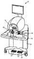
도 1a는 본 발명의 실시예에 따른 MIS 시스템의 정면도이다.
도 1b는 도 1a의 MIS 시뮬레이터의 사시도이다.
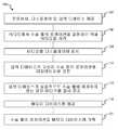
도 2a는 본 발명의 다른 실시예에 따른 방법을 설명하는 순서도이다.
도 2b는 본 발명의 실시예에 따른 다른 방법을 설명하는 순서도이다.
도 3은 MIS의 비디오로부터의 이미지이다.
도 4a는 그레이 레벨 임계화에 의한 처리후의 도 3의 이미지이다.
도 4b는 HSL 스레스홀딩에 의한 처리후의 도 3의 이미지이다.
도 5a는 부식에 의한 처리후의 도 4b의 이미지이다.
도 5b는 확장에 의한 처리후의 도 5a의 이미지이다.
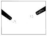
도 6은 에지 검출에 의한 처리후의 도 5b의 이미지이다.
도 7은 추가 처리후의 도 5b의 이미지이다.
도 8은 특징 인식 기술을 사용한 후의 도 7의 이미지이다.
도 9a는 이미지 처리후의 사용자 선택가능한 파라미터를 보여주는 대화창이다.
도 9b는 이미지 처리후의 추가적인 사용자 선택가능한 파라미터를 보여주는 다른 대화창이다.
도 10은 실습자를 훈련시키기 위한 가상 도구가 중첩된, MIS의 비디오로부터의 이미지이다.In order to better understand the features and objects of the present invention, the following detailed description has been given in conjunction with the following drawings.
1A is a front view of a MIS system according to an embodiment of the present invention.
FIG. 1B is a perspective view of the MIS simulator of FIG. 1A.
2A is a flow chart illustrating a method according to another embodiment of the present invention.
2B is a flowchart illustrating another method according to an embodiment of the present invention.
3 is an image from a video of the MIS.
4A is the image of FIG. 3 after processing by gray level thresholding.
4B is the image of FIG. 3 after processing by HSL thresholding.
5A is an image of FIG. 4B after treatment with corrosion.
5B is the image of FIG. 5A after processing by expansion.
6 is the image of FIG. 5B after processing by edge detection.
7 is the image of FIG. 5B after further processing.
8 is an image of FIG. 7 after using feature recognition technology.
9A is a dialog showing user selectable parameters after image processing.
9B is another dialog showing additional user selectable parameters after image processing.
10 is an image from a video of a MIS, with virtual tools for training practitioners superimposed.
본 발명은 최소 침습 수술("MIS")의 비디오를 사용하는 MIS 방법(100)으로서 구현될 수 있다. 비디오는 예를 들어, 외과의에 의해 행해지는 최소 침습 수술("MIS")의 비디오일 수 있다. 본 발명의 실시예에서, 비디오 자체 및 이러한 비디오를 포착하는 것은 본 발명의 일부가 아니다. 따라서, 비디오는 본 발명의 외부의 프로세스에 의해 포착될 수 있다. 이러한 비디오는 당업계에 공지된 바와 같이 저장 매체(예를 들어, 테이프, 디스크, 하드드라이브, 플래시 드라이브등)에 사전 기록될 수 있거나, 비디오는 실시간 행해지는 수술의 라이브 비디오일 수 있다. 비디오는 각 프레임이 임의의 시점에서 적어도 하나의 이미지인 복수의 프레임을 포함한다. 한 예에서, 비디오는 로봇 도구중 하나가 보이는 다빈치®서지컬 시스템("DVSS")을 사용한 전립선 절제술을 보여줄 수 있다. 이러한 도구는 메스, 가위, 또는 보비를 포함할 수 있지만 이에 제한되는 것은 아니다. 비디오 예의 이미지는 2개의 수술 도구가 보이는 도 3에 도시되어 있다. 또 다른 예에서, 비디오는 종래의(로봇이 아닌) 복강경 프로시저를 보여줄 수 있다. 적합한 MIS 프로시저의 다른 비디오가 당업자에게 명백할 것이다. 비디오에서, 적어도 하나의 수술 도구를 볼 수 있다. 적어도 하나의 수술 도구는 예를 들어, 파지, 봉합, 뜸 등과 같은 작업을 수행할 수 있다.The present invention can be implemented as
비디오는 서로 고정된 2개의 관점에서 포착된 입체 비디오일 수 있고, 이러한 경우에, 비디오의 각 프레임은 2개의 이미지를 갖는 것으로 생각될 수 있다. 비디오는 "3차원 비디오"로서 관찰될 수 있다. 이러한 3차원 표현은 2개의 2차원 이미지/비디오로부터 재구성된다. 이러한 타입의 3차원 구성은 자주 2.5차원 (2½ 차원)으로 불린다. 3차원 및 2.5차원은 본원에서 상호교환되어 사용될 수 있다.The video may be stereoscopic video captured from two viewpoints fixed to each other, in which case each frame of the video may be considered to have two images. The video can be viewed as a "three-dimensional video." This three-dimensional representation is reconstructed from two two-dimensional images / videos. This type of three-dimensional configuration is often called 2.5 (2½) dimensions. Three and 2.5 dimensions can be used interchangeably herein.
비디오는 수술 동안 외과의 및/또는 수술실 스탭에 의해 사전 기록될 수 있다. 대안으로, 비디오는 본 발명에 따른 MIS 훈련과 동시에 실행되는 수술 프로시저로부터의 비디오일 수 있다("라이브 피드"). 다른 대안에서, 비디오는 수술 또는 다른 훈련 작업(예를 들어, 픽-앤-플레이스 연습)을 실행하도록 수술 시물레이터를 사용하는 사람에 의해 취해진 비디오일 수 있다. 이러한 비디오를 포착하는 방법 또는 비디오를 포착하는 단계는 본 발명의 일부를 구성하지는 않는다.The video may be pre-recorded by the surgeon and / or operating room staff during the surgery. Alternatively, the video may be a video from a surgical procedure executed concurrently with MIS training according to the present invention (“live feed”). In another alternative, the video may be a video taken by a person using a surgical simulator to perform a surgery or other training task (eg, pick-and-place practice). The method of capturing such video or the step of capturing video does not form part of the present invention.
방법(100)은 프로세서, 프로세서와 통신하는 디스플레이 및 프로세서와 통신하는 제1 입력 디바이스를 제공하는 단계(103)를 포함한다. 시스템의 예인 Simulated Surgical Systems LLC의 Robotic Surgical Simulator("RoSS™")가 도 1에 도시되어 있다. 여기에서, 이러한 시스템을 설명하지만, Ross 시뮬레이터는 하나의 예이고 이에 제한되는 것은 아니다. 도 1의 시스템(10)에서, 프로세서(24), 디스플레이(14) 및 제1 입력 디바이스(16)가 도시되어 있다. 디스플레이(14)는 당업계에 공지된 바와 같이 입체 디스플레이일 수 있다(이러한 예는 도 1에 도시되어 있다). 제1 입력 디바이스(16)는 실제 수술 디바이스의 모션을 최상으로 재생하도록 선택될 수 있다. 하나의 예에서, (PHANTOM®Omni®와 같은) 6개의 자유도 디바이스가 DVSS의 입력으로서 모션을 재생성하기 위해 제1 입력 디바이스(16)으로서 선택될 수 있다.The
방법(100)은 각 프레임내의 제1 수술 도구의 로케이션을 결정하도록 프로세서(24)를 사용하여 비디오를 처리하는 단계(106)를 포함한다. 비디오 처리 기술(106)은 아래에서 보다 설명된다. 방법(100)은 디스플레이(14)에 비디오를 표시하는 단계(109)를 포함한다.The
방법(100)은 제1 입력 디바이스(16)의 구성이 비디오가 표시되는 동안 비디오의 각 프레임의 제1 수술 도구의 로케이션에 실질상 상응하는지 여부를 결정하는 단계(112)를 포함한다. 사용에서, 디스플레이(14)에서 비디오를 관찰하는 실습자는 스크린상의 제1 수술 도구의 모션에 상응하는 모션을 만들고 이러한 모션(각 시점에서의 로케이션)이 실질상 상응하는지 여부에 대해 결정하기 위해 제1 입력 디바이스(16)를 조작할 것이다. 추가 훈련 단계가 모션이 상응하는지 여부에 따라 취해질 수 있다. 예를 들어, 비디오는 제1 입력 디바이스(16)의 구성이 제1 수술 도구의 위치에 실질상 상응하지 않는다면 일시정지될 수 있다(115).The
방법(100)은 메모리 디바이스를 제공하는 단계(118) 및 이러한 메모리 디바이스에 비디오의 각 프레임의 적어도 하나의 수술 도구의 로케이션을 기록하는 단계(121)를 더 포함할 수 있다.The
제2 수술 도구가 비디오에서 보여지는 경우에, 본 발명의 방법은 (i) 제1 및 제2 수술 도구의 각각의 로케이션을 결정하기 위해 컴퓨터를 사용하여 비디오를 처리할 수 있고 (ii) 제2 입력 디바이스의 구성이 비디오가 표시되는 동안 비디오의 각 프레임의 제2 수술 도구의 로케이션에 실질상 상응하는지 여부를 추가로 결정할 수 있다.If a second surgical instrument is shown in the video, the method of the present invention can (i) process the video using a computer to determine respective locations of the first and second surgical instruments and (ii) the second It may further be determined whether the configuration of the input device substantially corresponds to the location of the second surgical tool of each frame of the video while the video is displayed.
각 프레임의 제1 수술 도구의 로케이션을 결정하기 위해 비디오를 제공하는 단계(106)는 적어도 하나의 수술 도구의 물리적 특성 데이터를 획득하는 단계(150)를 포함할 수 있다. 물리적 특성 데이터는 컬러, 길이, 폭, 직경, 형상등과 같은 적어도 하나의 수술 도구에 대한 정보를 포함할 수 있다. 물리적 특성 데이터는 예를 들어, 제한되지 않은 파일과 같은 기계 판독가능 포맷일 수 있다. 물리적 데이터는 데이터 입력 디바이스를 사용하여 사람에 의해 입력될 수 있다.Providing
비디오를 처리하는 단계(106)는 복수의 특징을 검출하기 위해 비디오의 제1 프레임을 처리하는 단계(153)를 더 포함할 수 있다. 특징은, 여기에 한정되는 것은 아니고, 예를 들어 관심 영역의 에지, 코너, 지점, 영역 또는 관심 영역의 중심을 포함할 수 있다. 특징은 이미지 처리 또는 비디오 처리 기법(컴퓨터 비전 등)을 통해 식별 및/또는 추적될 수 있는 비디오(또는 비디오의 이미지)의 상기 특징이 될 수 있다. 처리 기법은 후술되고 다른 처리 기법은 이미 공지되어 있다.Processing 106 may further include processing 153 a first frame of video to detect a plurality of features. The feature is not limited thereto, and may include, for example, an edge, corner, point, area of interest region or the center of region of interest. The feature may be the feature of a video (or image of a video) that can be identified and / or tracked through image processing or video processing techniques (such as computer vision). Processing techniques are described below and other processing techniques are already known.
적어도 하나의 수술 툴의 적어도 하나의 툴 특징은 적어도 하나의 수술 툴의 물리적인 특성 데이터를 이용하여 식별될 수 있다(156). 검출된 복수의 특징은 적어도 하나의 툴 특징을 파악하기 위해 파스될 수 있다. 제한되지 않는 예로서, 본 발명을 구현하는 방법은 적당한 길이이고, 적당한 거리에 있는(폭에 대응) 다른 에지로부터 떨어지고 거의 평행한 툴 에지를 식별할 수 있다.At least one tool feature of the at least one surgical tool may be identified 156 using physical characteristic data of the at least one surgical tool. The detected plurality of features may be parsed to identify at least one tool feature. By way of non-limiting example, the method of implementing the present invention can identify tool edges that are of a suitable length and that are nearly parallel to and away from other edges at a suitable distance (corresponding to width).
적어도 하나의 툴 특징의 위치는 제1 프레임내에 적어도 하나의 수술 툴의 로케이션을 결정하기 위해 계산될 수 있다(159). 비디오를 처리하는 단계(106)는 비디오 각각의 프레임에 대한 프레임-특정 단계(153, 156, 159)의 각각을 반복하는 단계(162)를 더 포함할 수 있다. 따라서, 다음 프레임이 특징을 식별하기 위해 처리되고(153), 물리적인 특성 데이터를 사용하여 적어도 하나의 툴 특징이 식별되고(156), 각 프레임내에서 적어도 하나의 수술 툴의 로케이션을 결정하기 위해 적어도 하나의 툴 특징의 위치가 계산된다(159). 비디오의 각 프레임에서 툴 위치 데이터는 수술 트레이닝동안 객관적인 메트릭을 정의하는 데 도움이 되는, 적어도 하나의 수술 툴의 운동이나 궤적의 분석에 더 사용될 수 있다.The location of the at least one tool feature can be calculated 159 to determine the location of the at least one surgical tool in the first frame. Processing the
비디오가 입체적인 비디오라면, 입체시각에 관련된 알고리즘이 적어도 하나의 수술 툴의 3차원 로케이션 좌표를 결정하기 위해 사용될 수 있다(200). 예를 들어, 여기에 한정되는 것은 아니지만, 칼만-필터(Kalman-Filter)와 같은 알고리즘이 3차원 좌표를 결정하기 위해 사용될 수 있다.If the video is stereoscopic video, an algorithm related to stereoscopic vision may be used to determine the three-dimensional location coordinates of the at least one surgical tool (200). For example, but not limited to, an algorithm such as Kalman-Filter can be used to determine three-dimensional coordinates.
비디오를 처리하는 단계(106)의 다른 실시예에서, 비디오의 적어도 두개의 프레임이 적어도 2개의 프레임의 제1 프레임에서 상기 적어도 2개의 프레임의 제2 프레임으로 로케이션을 변경하는 적어도 하나의 대상을 검출하기 위해 처리될 수 있다(180). 대상은 적어도 하나의 수술 툴이 될 수 있다. 이 처리는 광학 플로우로 언급될 수 있고, 예시적인 구현이 후술된다("타겟 표현 및 로컬리제이션 예")In another embodiment of
로케이션을 변경하는 적어도 하나의 대상을 검출하기 위해 비디오를 처리하는 단계(180)의 일 실시예는 비디오의 적어도 두개의 프레임의 복수의 섹션의 속도 필드를 계산하는 단계(183)를 포함한다. 미리 결정된 임계 파라미터가 유사하고 논-제로 속도 필드를 가진 적어도 두개의 프레임의 섹션을 적어도 하나의 관심 영역으로 조합하고 식별하는 단계(186)를 포함한다. 이와 같이, 유사하고(미리 결정된 임계 파라미터에 의해 정의되는) 논-제로 속도 필드를 가지는 적어도 두개의 프레임의 섹션이 식별된다. 식별된 섹션은 조합된다. 각 섹션은 개별적인 픽셀이거나 한 그룹의 픽셀일 수 있다. 적어도 하나의 관심 여역의 중심은 적어도 하나의 대상의 로케이션으로서 결정된다(189). 중심은 각 프레임에서 적어도 하나의 대상의 로케이션을 결정하기 위해 비디오의 각 프레임내에서 결정된다(192). 적어도 하나의 대상은 수술 툴이 될 수 있다.One embodiment of
트래킹 기술 예Tracking technique example
비디오 이미지에 타겟을 위치시키기 위한 2개의 기술이 본 발명의 실시예로서 상세하게 설명된다. 그러나, 본 발명은 이러한 예에 제한되지 않는다.Two techniques for positioning a target in a video image are described in detail as an embodiment of the present invention. However, the present invention is not limited to this example.
"타겟 표현 및 로컬리제이션" 기술은 바텀업 프로세스로서 볼 수 있다. 이러한 방법은 이동하는 대상을 식별하기 위한 다양한 툴을 제공한다. 타겟 대상을 성공적으로 위치시키고 트래킹하는 것은 알고리즘에 의존한다. 예를 들어, 블롭 트래킹은 사람의 프로파일이 동적으로 변하기 때문에 인간 이동을 식별하는데 사용된다. 보통 이러한 알고리즘에 대한 계산의 복잡도는 낮다.The "target representation and localization" technique can be viewed as a bottom up process. This method provides various tools for identifying moving objects. Successfully positioning and tracking the target object depends on the algorithm. For example, blob tracking is used to identify human movement because a person's profile changes dynamically. Usually the computational complexity for these algorithms is low.
"필터링 및 데이터 어소시에이션" 기술은 일반적으로 씬 또는 대상에 대한 이전 정보를 통합하는 단계, 대상 다이나믹을 어드레싱하는 단계, 상이한 가설의 평가를 포함하는 탑다운 프로세스이다. 이러한 방법으로 인해 방해 뒤에 이동하는 대상을 추적하는 것과 같은 보다 복잡한 대상 인터랙션을 따른 복잡한 대상의 추적이 가능하다. 이러한 알고리즘에 대한 계산의 복잡도는 보통 보다 더 높다.A "filtering and data association" technique is generally a top-down process that includes integrating previous information about a scene or object, addressing object dynamics, and evaluating different hypotheses. This approach allows tracking of complex objects along more complex object interactions, such as tracking objects moving behind the disturbance. The computational complexity for these algorithms is higher than usual.
필터링 및 데이터 오소시에이션 기술 예Examples of Filtering and Data Association Techniques
비디오를 구성하는 이미지(프레임)은 적어도 하나의 수술 도구가 이미지의 배경으로부터 보다 돋보이도록 강화될 수 있다. 일부 실시예에서, 이미지의 배경은 수술 환경, 즉, 조직 및 환자의 다른 구조일 것이다. 특정 예(이미지 처리 단계의 선택)의 언급을 포함하는 다양한 이미지 처리 옵션이 아래에 설명되어 있다. 이러한 옵션 및 특정 예는 제한을 위한 것이 아니다. 다른 이미지 처리 기술이 당업계에 공지되어 있고 본 발명의 범위내에 있다. 본 발명의 방법(100)에서, 하나 이상의 필터가 비디오의 프레임에 적용될 수 있다(115).The images (frames) that make up the video may be enhanced so that at least one surgical instrument stands out from the background of the image. In some embodiments, the background of the image will be the surgical environment, ie tissue and other structures of the patient. Various image processing options are described below, including mention of specific examples (selection of image processing steps). These options and specific examples are not intended to be limiting. Other image processing techniques are known in the art and are within the scope of the present invention. In the
2개의 바늘 도구가 추적되는 특정 예를 설명한다. 각 바늘 도구는 베이스를 갖고 있는 긴 샤프트 및 관절 조인트를 포함한다. 샤프트의 베이스는 자유롭게 회전하도록 한다. 이러한 예의 비디오는 상이한 각으로부터 동일한 씬의 이미지의 세트를 생성하도록 서로 경미하게 오프셋된 2개의 카메라를 사용하여 생성된 입체 비디오이다. 이러한 입체 비디오는 MIS의 3차원 비디오를 생성하는데 사용될 수 있다. 이러한 예의 목적은 2개의 별개의 비디오 카메라에 의해 포착된 2개의 수술 도구를 추적하고 도구의 위치를 찾아내는 것이었다. 다음을 가정한다.A particular example is described where two needle tools are tracked. Each needle tool includes an elongated shaft and articulation joint with a base. The base of the shaft is allowed to rotate freely. This example video is stereoscopic video created using two cameras slightly offset from each other to produce a set of images of the same scene from different angles. Such stereoscopic video can be used to generate three-dimensional video of the MIS. The purpose of this example was to track and locate the two surgical instruments captured by two separate video cameras. The following are assumed.
1. 도구는 분석 전에 공지된 특징(예를 들어, 컬러, 수, 길이등)에 의해 표시될 수 있다.1. The tool may be indicated by known features (eg color, number, length, etc.) prior to analysis.
2. 도구는 직선을 사용하여 정의될 수 있는 대상일 뿐이다.2. A tool is just an object that can be defined using straight lines.
비디오 입력으로부터 이미지 추출하기Extract Image from Video Input
비디오는 일반적으로 시간을 두고 취해진 복수의 스틸 이미지로 구성되어 있다. 본 발명에 사용된 비디오는 먼저, 비디오로부터 별개의 이미지(프레임)을 추출하도록 파싱될 수 있다. 이러한 예에서, openCV 애플리케이션 프로그래밍 인터페이스("API")는 카메라에 의해 포착된 툴 모션의 비디오로부터 이미지 프레임을 추출하는데 사용되었다. 이러한 이미지의 각각은 추가 이미지 처리를 위한 입력으로 기능하였다. 본 예에서, 비디오-이러한 비디오의 각 프레임-는 720x486 픽셀로 측정되었다(보통, 와이드 스크린 포맷). 도 3은 2개의 수술 도구(50, 52) 및 환자의 복부의 내부를 보여주는 샘플 이미지이다. 본 발명의 방법(100)은 비디오로부터 프레임을 추출하는 단계, 비디오로부터 각 프레임을 연속으로 추출하는 단계, 및/또는 비디오로부터 모든 프레임을 추출하는 단계를 포함할 수 있다.Video generally consists of multiple still images taken over time. The video used in the present invention may first be parsed to extract a separate image (frame) from the video. In this example, the openCV application programming interface (“API”) was used to extract an image frame from the video of the tool motion captured by the camera. Each of these images served as input for further image processing. In this example, video—each frame of such video—was measured at 720x486 pixels (usually in wide screen format). 3 is a sample image showing the interior of two
물리적 특성 데이터 검색Retrieve Physical Property Data
도구의 특성(물리적 특성)이 포착되었고 검색되어 이미지 처리 동안 사용되었다(예를 들어, 컬러(RGB 포맷), 길이, 폭등). 컬러 정보가 제공되었다면, 임계화(하술됨) 동안 사용되었고, 다른 특성이 특징 검출(하술됨) 동안 사용되었다. 본 예에서, 720x486 해상도의 이미지의 툴 샤프트의 길이는 대략 200개의 화소이다.The properties of the tool (physical properties) were captured and retrieved and used during image processing (eg color (RGB format), length, width, etc.). If color information was provided, it was used during thresholding (described below) and other characteristics were used during feature detection (described below). In this example, the tool shaft length of the image at 720x486 resolution is approximately 200 pixels.
사전 처리 - 노이즈/클러터Preprocessing-Noise / Clutter
이미지 내의 노이즈 및 클러터를 감소시키기 위해 이미지를 여과시키는 것이 유익할 수 있다. 노이즈는 화소 휘도 값에서의 랜덤 에러로서 정의될 수 있고, 클러터는 사용되지 않는 이미지 성분으로서 정의될 수 있다(환자 조직은 많은 양의 클러터를 포함할 수 있다). 노이즈 및 클러터는 필터를 적용함으로써 감소될 수 있다. 예를 들어, 블러링(애브리징) 필터, 가우시안 블러 필터 및/또는 메디안 필터가 이미지에 적용될 수 있다. 가우시안 블러 필터는 이미지로부터 고주파수를 제거할 것이어서 저역통과 필터로 생각될 수 있다. 메디안 필터는 알고리즘을 필터링함으로써 변하는 룰에 따라 이웃하는 화소의 메디안 값으로 화소를 대체한다. 메디안 필터는 이미지 내의 에지의 과도한 블러링 없이 "임펄스 노이즈"를 상당히 감소시킨다. 메디안 및 가우시안 필터 모두는 노이즈/클러터 감소에 적합하지만 메디안 필터는 이미지내의 에지를 보존하는데 보다 더 적합하다. 상이한 필터를 사용한 상당한 테스팅 후에 메디안 필터 기술이 본 예를 위해 사용되었다.It may be beneficial to filter the image to reduce noise and clutter in the image. Noise can be defined as a random error in pixel luminance values, and clutter can be defined as an unused image component (patient tissue can include a large amount of clutter). Noise and clutter can be reduced by applying a filter. For example, blurring (bridging) filters, Gaussian blur filters, and / or median filters may be applied to the image. A Gaussian blur filter will remove high frequencies from the image and can therefore be thought of as a lowpass filter. The median filter replaces the pixel with the median value of neighboring pixels according to the rules that change by filtering the algorithm. The median filter significantly reduces the "impulse noise" without excessive blurring of the edges in the image. Both median and Gaussian filters are suitable for noise / clutter reduction, but median filters are more suitable for preserving edges in an image. The median filter technique was used for this example after significant testing with different filters.
사전-처리 - 임계화Pre-processing-Thresholding
본 발명의 발명에서, 임계화가 이진 이미지 (또는 다른 양자화된 이미지)를 제공하기 위해 사용될 수 있다. 임계화는 특정 특성의 임계값과 비교되는 특정 특성에 기초한 새로운 값이 화소에 할당되는 이미지 처리 기술이다. 예를 들어, 임계화는 이러한 화소의 휘도에 기초하여 화소에 새로운 값을 할당할 수 있다. 또 다른 예에서, 임계화는 (적합한 컬러 스페이스, 예를 들어, 적, 녹, 청("RGB"), 휴-새튜어레이션-루미노시티("HSL") 등을 사용하여) 그 컬러에 기초하여 화소에 새로운 값을 할당할 수 있다. 임계화는 이진 이미지, 즉, 각 화소에 대한 오직 2개의 가능한 값을 갖는 이미지를 생성하는데 유용하다. 본 예에서, 이진 이미지는 에지 검출을 포함하는 다른 단계에 적합하다.In the present invention, thresholding can be used to provide a binary image (or other quantized image). Thresholding is an image processing technique in which a pixel is assigned a new value based on a particular characteristic compared to a threshold of that particular characteristic. For example, thresholding may assign a new value to a pixel based on the luminance of such a pixel. In another example, thresholding may be applied to that color (using a suitable color space, eg, red, green, blue ("RGB"), hue-saturation-luminosity ("HSL"), etc.). A new value can be assigned to the pixel based on that. Thresholding is useful for creating binary images, ie images with only two possible values for each pixel. In this example, the binary image is suitable for other steps including edge detection.
본 예에서, HSL 값에 기초한 임계화(도 4b)는 휘도 임계 기술(도 4a) 보다 양호한 결과를 산출하는 것으로 증명되었다. HSL 임계화는 이미지가 또 다른 컬러 스페이스로부터 전환된 컬러 임계화로부터 희망 결과를 얻기 위한 유용한 방법이다. HSL과 같은 컬러 스페이스는 컬러 휴, 포화 및 루미노시티(휘도)의 특성이 별개로 언급될 수 있기 때문에, 즉 광범위한 입력 휘도가 기대되는 경우 루미노시티에 대한 보다 더 수용가능한 필터가 허용되기 때문에 보다 양호하게 설계된 필터를 얻을 수 있다. 특정 데이터 세트에 대해, HSL 임계화로 인해 (상술된) 노이즈/클러터 감소 동작이 불필요할 수 있다. HSL 값에 기초한 임계화로부터의 출력은 매우 적은수의 원치않는 화소를 갖는 이진 이미지를 제공한다.In this example, thresholding based on HSL values (FIG. 4B) has been demonstrated to yield better results than luminance thresholding techniques (FIG. 4A). HSL thresholding is a useful way to achieve the desired result from color thresholding where an image has been converted from another color space. Color spaces such as HSL can be referred to separately as the characteristics of color hues, saturation and luminosity (brightness), ie, because a more acceptable filter for luminosity is allowed when a wide range of input luminance is expected. A better designed filter can be obtained. For certain data sets, noise / clutter reduction operations (described above) may be unnecessary due to HSL thresholding. The output from thresholding based on the HSL value provides a binary image with very few unwanted pixels.
사전-처리 - 몰폴로지컬 동작Pre-processing-Morphological Behavior
본 발명의 발명은 노이즈 화소의 수를 감소시키고 이미지 내의 비연속성을 해결하기 위해 몰폴로지컬 펑션을 사용할 수 있다. 부식 및 소거는 요구되는 출력을 생성하기 위해 독립적으로 또는 함께 사용될 수 있는 몰폴로지컬 동작의 방법이다. 부식은 이미지내의 화소의 블롭의 크기를 감소시킬 것이고 확장은 블롭의 주변으로부터 화소를 더하거나 감하여(화소의 휘도값) 이러한 블록의 크기를 증가시킬 것이다. 비전 처리를 위해, 이러한 펑션은 이미지 내의 화소의 보다 작은 블록을 강조하거나 제거할 수 있기 때문에 유용하다. 또한, 먼저 확장을 적용한 후에 부식(소위 "클로징")함으로써 화소의 인접한 블롭은 연결되도록 할 수 있고, 역순의 적용(소위 "오프닝")은 블롭의 일반적인 크기를 변경함없이 연결해제되도록 할 수 있다. 이러한 몰폴로지컬 동작은 노이즈 화소의 수를 더 감소시키고 및/또는 이미지 내의 비연속성을 감소시키는데 적합한다. 예를 들어, 소수의 이격된 화소는 균일한 라인을 생성하기 위해 확장될 수 있다. 이러한 동작은 이진 이미지에 최상으로 동작하지만 논-이진 이미지 역시 사용될 수 있다. 몰폴로지컬 동작에서, (특정 형상의) 구조적 엘리먼트는 이미지를 "프로빙"하고 이미지 내의 구조의 형상을 감소(부식)시키거나 팽창(확장)시키는데 사용된다.The invention of the present invention can use morphological functions to reduce the number of noise pixels and to solve discontinuities in the image. Corrosion and elimination is a method of morphological operation that can be used independently or together to produce the required output. Erosion will reduce the size of the blobs of the pixels in the image and expansion will increase the size of these blocks by adding or subtracting pixels from the periphery of the blob (the luminance value of the pixels). For vision processing, this function is useful because it can highlight or remove smaller blocks of pixels in the image. Also, by applying expansion first and then corroding (so-called "closing"), adjacent blobs of pixels can be connected, and the reverse application (so-called "opening") can be disconnected without changing the general size of the blob. . This morphological operation is suitable for further reducing the number of noise pixels and / or reducing discontinuities in the image. For example, a few spaced apart pixels can be expanded to produce uniform lines. This operation works best with binary images, but non-binary images can also be used. In morphological operations, structural elements (of a particular shape) are used to "probe" an image and to reduce (corrode) or expand (expand) the shape of the structure within the image.
부식은 다음과 같이 표현될 수 있다.Corrosion can be expressed as follows.

여기에서, A는 이진 이미지이고 B는 구조 엘리먼트이다. 구조 엘리먼트가 센터를 가질 때, 이진 이미지 A의 부식은 B가 이진 이미지 A의 구조 내에서 이동되기 때문에 B의 센터에 의해 도달되는 포인트의 세트로서 이해될 수 있다.Where A is a binary image and B is a structural element. When the structural element has a center, the corrosion of binary image A can be understood as a set of points reached by the center of B because B is moved within the structure of binary image A.
확장은 다음과 같이 표현될 수 있다.Extensions can be expressed as

여기에서, 구조적 엘리먼트 B는 센터를 갖고 있고, 이진 이미지 A의 확장은 B의 센터가 이진 이미지 A의 구조를 따라 이동되기 때문에 B의 주변에 의해 도달되는 포인트의 세트로서 이해될 수 있다.Here, structural element B has a center and expansion of binary image A can be understood as a set of points reached by the periphery of B because the center of B is moved along the structure of binary image A.
본 예에서, 이미지는 먼저 부식된 후 확장되었고 이로 인해, 연결해제된 화소가 연결되었다(도 5a(부식) 및 도 5b(확장) 참조).In this example, the image was first corroded and then expanded, thereby disconnecting the disconnected pixels (see FIGS. 5A (corrosion) and 5B (expansion)).
사전-처리 - 에지 검출Pre-processing-Edge Detection
본 발명의 방법은 비디오의 프레임에 에지 검출 기능을 적용할 수 있다. 에지 검출은 분할 또는 "에지"로 보통 표시되는 (컬러, 휘도 또는 다른 적합한 특성에서의) 급격한 변화 대신에 이미지를 스캐닝하는 단계를 포함한다. 상이한 타입의 이미지에 보다 양호하게 각가 실행되는, 사용될 수 있는 다수의 방법이 존재한다. 제1 데리베이티브(보통 서치 기반 방법) 및 2차 데리베이티브(보통 제로크로싱 기반 방법) 정보를 사용하는 에지 검출 알고리즘이 존재한다. 예를 들어, 소벨 오퍼레이터 또는 라플라시안 오퍼레이터를 사용하는 알고리즘이 그래디언트 편차, 그래서 에지를 검출하도록 사용될 수 있다.The method of the present invention can apply an edge detection function to a frame of video. Edge detection involves scanning the image instead of abrupt changes (in color, brightness or other suitable characteristics) that are usually indicated by segmentation or " edges. &Quot; There are a number of methods that can be used, in which angles are better performed on different types of images. There is an edge detection algorithm that uses first derivative (usually search based method) and second derivative (usually zero crossing based method) information. For example, algorithms using Sobel operators or Laplacian operators can be used to detect gradient deviations, so edges.
본 예에서, "캐니" 에지 검출 알고리즘이 사용되었다. 캐니 알고리즘은 제로크로싱 알고리즘의 타입이고, 이는 2차 미분의 제로 크로싱을 체크한다는 것을 의미한다. 캐니 알고리즘은 소벨 오퍼레이터를 적용함으로써 임계화를 획득된 출력에 적용하고 이미지 내의 모든 가능한 에지를 포함하는 이진 이미지를 생성한다. 파라미터는 에지의 크기를 개선하기 위해 펑션에서 선택될 수 있다. 캐니 알고리즘으로부터 획득된 샘플 이미지는 도 6에 도시되어 있다.In this example, a "canny" edge detection algorithm was used. The Canny algorithm is a type of zero crossing algorithm, which means to check the zero crossing of the second derivative. The Canny algorithm applies the thresholding to the obtained output by applying the Sobel operator and produces a binary image that includes all possible edges in the image. The parameter may be selected in the function to improve the size of the edge. Sample images obtained from the Canny algorithm are shown in FIG. 6.
사전-처리 - 휴 변환Pre-processing-Hugh transformation
본 발명의 방법은 에지를 세트중에 툴 에지 후보의 세트를 결정하기 위해 휴 변환을 사용할 수 있다. 휴 변환은 이미지로부터 특성(본 경우에는 에지)를 추출하기 위한 기술이다. 휴 스페이스는 특정 형상이 이미지 내의 로케이션에 존재할 확률을 기술하는 이미지 스페이스이다. OpenCV API는 이미지 내의 직선(cvHoughLines2) 또는 원(cvHoughCricles)의 경우를 식별하기 위해 휴 변환을 사용하는 2개의 펑션을 포함한다. 양측 펑션은 모두 입력 이미지가 그레이스케일/이진 (단일 채널)이 될 것을 요구한다. 라인 펑션은 모든 가능한 라인을 포함하는 어레이를 리턴하고, 이것은 특징 검출에 사용된다.The method of the present invention may use a Hugh transform to determine the set of tool edge candidates in the set of edges. Hugh transform is a technique for extracting features (in this case edges) from an image. Hue space is an image space that describes the probability that a particular shape exists at a location in the image. The OpenCV API includes two functions that use the Hugh transform to identify the case of straight lines (cvHoughLines2) or circles (cvHoughCricles) in the image. Both functions require the input image to be grayscale / binary (single channel). The line function returns an array containing all possible lines, which is used for feature detection.
본 예에서, cvHoughLines2는 도 7의 이미지에 존재하는 라인의 로케이션을 결정하는데 사용되었다. 최종 어레이는 툴 후보의 세트로 생각될 수 있다. 이러한 툴 후보의 세트는 툴 특성(물리적 특성 데이터)에 기초하여 툴을 인식하는데 사용되었다.In this example, cvHoughLines2 was used to determine the location of the lines present in the image of FIG. The final array can be thought of as a set of tool candidates. This set of tool candidates was used to recognize the tool based on the tool characteristics (physical characteristic data).
특징 검출 및 대상 인식Feature detection and object recognition
본 발명의 방법은 툴 에지 후부로부터 적어도 하나의 툴 에지를 결정하기 위해 물리적 특성 데이터를 사용할 수 있다. 본 예에서, 툴 후보의 세트가 상술된 기술(또는 적합한 다른 기술)을 사용하여 이미지로부터 결정된 후에, 수술 도구를 정의하는 라인은 이러한 세트로부터 식별될 수 있다. 물리적 특성 데이터가 사용되었다. 예를 들어, 이러한 툴의 길이는 적합한 길이의 후보의 세트에서 라인을 결정하는데 사용되었다. 또한, 툴 폭은 적합한 거리 이격된 라인을 결정하는데 사용되었다. 또한, 적합한 라인의 경사는 툴의 샤프트가 2개의 실질상 평행한 라인에 의해 식별되기 때문에 결정될 수도 있다. 일반적인 이미지 분석 데이터를 가진 표준 IF-ELSE 후보의 형태의 이러한 도메인 지식을 사용하여, 각 툴 샤프트는 이미지에서 식별되었다(도 8 참조).The method of the present invention may use physical property data to determine at least one tool edge from behind the tool edge. In this example, after a set of tool candidates has been determined from an image using the technique described above (or other suitable technique), the line defining the surgical tool can be identified from this set. Physical property data was used. For example, the length of this tool was used to determine the line in the set of candidates of the appropriate length. In addition, the tool width was used to determine suitable distanced lines. In addition, the slope of the suitable line may be determined because the shaft of the tool is identified by two substantially parallel lines. Using this domain knowledge in the form of standard IF-ELSE candidates with general image analysis data, each tool shaft was identified in the image (see FIG. 8).
툴 로케이션 결정Determine tool location
툴의 에지를 정의하는 식별된 라인의 엔드 포인트는 툴의 2-D 코디네이트를 추출하기 위해 사용되었다. 또한, 툴의 특징을 사용하여, 툴의 2차원 방위가 결정되었다. (2개의 상이한 카메라로부터 동시에 취해진) 입체 비디오의 2개의 상응하는 이미지를 분석함으로써, 툴 팁의 3차원 로케이션 및 툴의 방위가 결정되었다.The endpoint of the identified line defining the edge of the tool was used to extract the 2-D coordinates of the tool. In addition, using the features of the tool, the two-dimensional orientation of the tool was determined. By analyzing two corresponding images of stereoscopic video (taken simultaneously from two different cameras), the three-dimensional location of the tool tip and the orientation of the tool were determined.
타겟 표현 및 로컬리제이션 기술 예Target representation and localization techniques example
이러한 기술은 비디오의 프레임 내의 대상(본 경우에는, 수술 도구)의 명백한 모션을 추적하기 위해 "광 플로"의 개념을 사용한다. 이러한 예에서 도시된 광 플로 기술은 Horn-Schunck 방법 또는 Lucas-Kanade 방법을 사용한다. 다른 방법이 가능하고 본 범위내에 있다.This technique uses the concept of "light flow" to track the apparent motion of an object (in this case, a surgical tool) within a frame of video. The light flow technique shown in this example uses the Horn-Schunck method or the Lucas-Kanade method. Other methods are possible and within this scope.
하이 레벨에서, 다음의 제약 등식이 2개의 이미지 사이의 광 플로를 게산하기 위해 사용될 수 있다.At the high level, the following constraint equation can be used to calculate the light flow between the two images.

이러한 등식에서, Ix, Iy 및 It는 로케이션 x,y,t에서의 화소의 강도이고, u는 수평 광 플로이고, v는 수직 광 플로이다. 이러한 등식은 제약부족이지만, u 및 v를 풀기 위한 다수의 방법이 존재한다.In this equation, Ix, Iy and It are the intensity of the pixel at locations x, y, t, u is the horizontal light flow, and v is the vertical light flow. This equation is lacking, but there are many ways to solve u and v.
Horn-Schunck 방법Horn-Schunck Method
광학 플로우가 전체 이미지에 대해 스무드하다고 가정함으로써, Horn-Schunck 방법은 글로벌 에너지 펑셔널 등식을 최소화하는 속도 필드의 추정값을 계산한다.By assuming that the optical flow is smooth over the entire image, the Horn-Schunck method calculates an estimate of the velocity field that minimizes the global energy functional equation.

Horn-Schunck 방법은 다음의 등식에 의해 주어진, 이미지 내의 각 화소에 대하여, 속도 필드, [u, v]를 얻기 위해 이전의 등식을 최소화한다.The Horn-Schunck method minimizes the previous equation to obtain the velocity field, [u, v], for each pixel in the image, given by the following equation.

이러한 등식에서,
Horn-Schunck르 사용하는 본 발명의 실시예에 따른 방법은 제1 이미지 내의 각 화소에 대해 소벨 컨볼루션 커넬 및 그 트랜스포즈된 폼을 계산하고 사용함으로써 u 및 v에 대해 푼다. 그다음, 이러한 커넬을 사용하여 프레임 1과 2 사이를 계산한다. 이전의 속도가 0이라고 가정하고, 각 화소에 대해 평균 속도를 계산하고 컨볼루션 커넬로서 사용한다. 마지막으로, u 및 v에 대해 반복하여 푼다.The method according to an embodiment of the present invention using Horn-Schunck solves for u and v by calculating and using the Sobel convolution kernel and its transposed form for each pixel in the first image. Then use this kernel to calculate between
Lucas-Kanade 방법Lucas-Kanade method
u 및 v에 대해 광 플로우 제약 등식을 풀기 위해 Lucas-Kanade 방법은 오리지널 이미지를 보다 작은 섹션으로 분할하고 각 섹션에서 일정 속도를 가정한다. 그다음, 다음의 등식을 최소화함으로써 각 섹션에서의 일정 모델로의 광 플로 제약 등식의 가중치주어진 최소 제곱 피트를 실행한다.To solve the light flow constraint equations for u and v, the Lucas-Kanade method divides the original image into smaller sections and assumes constant velocity in each section. Then, the weighted least square feet of the light flow constraint equation to a constant model in each section are performed by minimizing the following equation.

여기에서 W는 각 섹션의 센터에서의 제약을 강조하는 윈도 펑션이다. 최소화 문제에 대한 솔루션은 다음의 식에 의해 주어진다.Where W is a window function that highlights the constraints at the center of each section. The solution to the minimization problem is given by the equation

블록은 가우시안 필터 또는 가우시안 필터의 데리베이티브(아래)를 사용하여 계산한다.Blocks are computed using Gaussian filters or the derivatives of Gaussian filters (below).
차이 필터:Difference filter:
커넬 및 그 트랜스포즈된 폼을 계산하고 사용한다. 고정된 포인트 데이터 타입에 대해, 커넬 값에 부호는 사인되고 워드 길이를 가진 고정된 포인트 값은 16이고 프랙션 길이는 15이다.Compute and use the kernel and its transposed form. For fixed point data types, the sign of the kernel value is signed and the fixed point value with the word length is 16 and the fraction length is 15.
1. 이미지 1과 2 사이를 커넬을 사용하여 계산한다.1. Calculate between
2. 그래디언트 컴포넌트를 스무딩하고 별개의 이소트로픽 5x5 엘리먼트 커넬을 사용한다. 고정된 포인트 데이터 타입에 대해, 커넬 값은 언사인되고, 워드 길이를 갖는 고정된 포인트 값은 8이고 프랙션 길이는 7이다.2. Smooth the gradient component and use a separate isotropic 5x5 element kernel. For a fixed point data type, the kernel value is unsigned, the fixed point value with the word length is 8 and the fraction length is 7.
3. 다음에 의해 각 화소에 대해 2x2 선형 등식을 푼다.3. Solve the 2x2 linear equation for each pixel by

고정된 포인트 다이어그램에서,In a fixed point diagram,

4. 고유값이 계산되었을 때, 이들 값은 사용자 선택가능한 임계 (노이즈 감소) 파라미터와 비교된다. 프레임 간의 작은 이동의 효과를 제거하도록 선택되고, 보다 높은 임계값일수록, 보다 적은 이동이 광 플로 계산에 영향을 준다. 그 결과는 다음의 케이스중 하나가 된다.4. When the eigenvalues have been calculated, these values are compared with a user selectable threshold (noise reduction) parameter. It is chosen to eliminate the effect of small movements between frames, and the higher the threshold, the less movement affects the light flow calculation. The result is one of the following cases:
- 케이스 1: A는 단수가 비특이하여서 블록은 그레이머의 룰을 사용하여 등식의 시스템을 푼다.Case 1: A is singular and the block solves the system of equations using Grammer's rules.
- 케이스 2: A는 특이하여서(비가역적이어서) 블록은 그래디언트 플로를 노멀화하여 u 및 v를 계산한다.Case 2: A is unique (nonreversible) so the block normalizes the gradient flow to compute u and v.
- 케이스 3: 광 플로, u 및 v는 0이다.Case 3: Light flow, u and v are zero.
가우시안의 데리베이티브Gaussian's Derivative
시간 필터링을 실행하기 위해 가우시안 필터를 계산하고 사용한다. 표준 편차 및 필터 계수의 수와 같은 특정 시간 필터 특성이 적절하게 선택된다.Compute and use Gaussian filters to perform time filtering. Specific time filter characteristics such as standard deviation and number of filter coefficients are appropriately selected.
공간 필터링을 사용하여 이미지를 부드럽게 하기 위해 가우시안 필터 및 가우시안 필터의 데리베이티브를 계산하고 사용한다. 이미지 스무딩 필터의 특정 표준 편차 및 길이는 적절하게 선택된다.Compute and use the derivatives of the Gaussian filter and Gaussian filter to smooth the image using spatial filtering. The particular standard deviation and length of the image smoothing filter is appropriately selected.
1. 다음의 단계를 사용하여 이미지 1과 2 사이를 계산한다.1. Calculate between
시간 필터링을 실행하기위해 가우시안 필터의 데리베이티브를 사용한다. 표준 편차 및 필터 계수의 수와 같은 특정 시간 필터 특성은 적절하게 선택된다.To perform temporal filtering, we use the derivative of the Gaussian filter. Specific time filter characteristics such as standard deviation and number of filter coefficients are appropriately selected.
a. 시간 필터의 출력에 공간 필터링을 실행하기 위해 필터를 사용한다.a. Use a filter to perform spatial filtering on the output of the temporal filter.
2. 그래디언트 컴포넌트를 부드럽게 하고 그래디언트 스무딩 필터를 사용한다. 그래디언트 스무딩 필터에 대한 표준 편차 및 필터 계수의 수는 적절하게 선택된다.2. Smooth out the gradient components and use the gradient smoothing filter. The number of standard deviations and filter coefficients for the gradient smoothing filter is appropriately selected.
3. 다음 방법을 사용하여 각 화소에 대한 2x2 선형 등식을 푼다.3. Solve the 2x2 linear equation for each pixel using the following method.

4. 고유값이 계산되었을 때, 이들은 사용자 선택가능한 임계(노이즈 감소) 파라미터와 비교된다. 프레임 사이의 작은 이동의 효과를 제거하기 위해 선택된다. 임계값이 높을 수록, 광 플로 계산에 보다 적은 이동이 영향을 준다. 이러한 결과는 다음의 케이스중 하나가 된다.4. When the eigenvalues have been calculated, they are compared to a user selectable threshold (noise reduction) parameter. It is selected to eliminate the effect of small shifts between frames. The higher the threshold, the less movement affects the light flow calculation. This result is one of the following cases:
- 케이스 1: A는 단수가 비특이하여서 블록은 그레이머의 룰을 사용하여 등식의 시스템을 푼다.Case 1: A is singular and the block solves the system of equations using Grammer's rules.
- 케이스 2: A는 특이하여서(비가역적이어서) 블록은 그래디언트 플로를 노멀화하여 u 및 v를 계산한다.Case 2: A is unique (nonreversible) so the block normalizes the gradient flow to compute u and v.
- 케이스 3: 광 플로, u 및 v는 0이다.Case 3: Light flow, u and v are zero.
소프트웨어 인터페이스Software interface
하나의 예에서, 상술된 광 플로 기술은 소프트웨어로 구현되었다. 광 플로 다이얼로그 박스의 메인 페인이 도 9a에 도시되어 있고, "데이터 타입" 페인이 도 9b에 도시되어 있다. 메인 필드 파라미터는 아래에 기술되어 있다.In one example, the light flow technique described above was implemented in software. The main pane of the optical flow dialog box is shown in FIG. 9A and the “data type” pane is shown in FIG. 9B. Main field parameters are described below.
Mehtod: 블록이 광 플로를 계산하기 위해 사용하는 방법을 선택한다. 선택은 "Horn-Schunck" 또는 "Lucas-Kanade"이다.Mehtod: Select the method the block uses to calculate the optical flow. The choice is "Horn-Schunck" or "Lucas-Kanade".
Compute optical flow between: 2개의 이미지 사이의 광 플로를 계산하기 위해 2개의 이미지를 선택한다. N 프레임 떨어진 2개의 비디오 프레임 사이의 광 플로를 계산하기 위해 "Current frame and N-th frame back"을 선택한다. 이러한 파라미터는 Method 파라미터가 ""Horn-Schunck" 또는 "Lucas-Kanade"로 설정되고 Temporal gradient filter가 "Difference filter [-1 1]"로 설정될 때 볼 수 있다.Compute optical flow between: Select two images to calculate the light flow between the two images. Select "Current frame and N-th frame back" to calculate the light flow between two video frames that are N frames apart. This parameter can be seen when the Method parameter is set to "Horn-Schunck" or "Lucas-Kanade" and the Temporal gradient filter is set to "Difference filter [-1 1]".
N: 기준 프레임과 현 프레임 사이의 프레임의 수를 나타내는 스케일러 값을 입력한다. 이러한 파라미터는 Compute optical flow between 파라미터가 N에 대한 값을 요구하는 선택으로 설정될 때 유용해진다.N: Enter a scaler value indicating the number of frames between the reference frame and the current frame. This parameter is useful when the Compute optical flow between parameter is set to a selection that requires a value for N.
Smoothness factor: 2개의 이미지 또는 비디오 프레임 사이의 상대 모션이 크다면, 큰 포지티브 스케일러 값을 입력한다. 상대 모션이 작다면, 작은 포지티브 스케일러 값을 입력한다. 이러한 파라미터는 Method 파라미터가 "Horn-Schunck"로 설정되어 있을 때 유용해진다.Smoothness factor: Enter a large positive scaler value if the relative motion between two image or video frames is large. If the relative motion is small, enter a small positive scaler value. This parameter is useful when the Method parameter is set to "Horn-Schunck".
Stop iterative solution: 블록의 반복 솔루션 프로세스가 정지할 때 제어하기 위해 이러한 파라미터를 사용한다. 속도차가 특정 임계값 아래에 있을 때 반복이 정지해야 한다면, "when velocity difference falls below threshold"를 선택한다. 특정 수의 반복 후에 반복이 정지해야 한다면, "when maximum number of iteration is reached"를 선택한다. 또한 "whichever comes first"에 대한 옵션도 존재한다. 이러한 파라미터는 Method 파라미터가 Horn-Schunck로 설정될 때 사용가능해진다.Stop iterative solution: Use this parameter to control when the iterative solution process of a block stops. If the iteration should stop when the speed difference is below a certain threshold, select "when velocity difference falls below threshold". If the iteration should stop after a certain number of iterations, select "when maximum number of iteration is reached". There is also an option for "whichever comes first". These parameters become available when the Method parameter is set to Horn-Schunck.
Maximum number of iterations: 블록이 실행해야 하는 반복의 최대수를 나타내는 스케일러 값을 입력한다. 이러한 파라미터는 "when maximum number of iteration is reached" 또는 "whichever comes first"가 Stop iterative solution 파라미터에 대해 선택되는 경우에만 볼 수 있다. 이러한 파라미터는 Method 파라미터가 Horn-Schunck로 설정될 때 사용가능해진다.Maximum number of iterations: Enter a scaler value indicating the maximum number of iterations the block should execute. This parameter is only visible if "when maximum number of iteration is reached" or "whichever comes first" is selected for the Stop iterative solution parameter. These parameters become available when the Method parameter is set to Horn-Schunck.
Velocity difference threshold: 스케일러 임계값을 입력한다. 이러한 파라미터는 Stop iterative solution 파라미터에 대해 "when velocity difference falls below threshold" 또는 "whichever comes first"가 선택되는 경우에만 볼 수 있다. 이러한 파라미터는 Method 파라미터가 Horn-Schunck로 설정될 때 사용가능해진다.Velocity difference threshold: Enter the scaler threshold. This parameter is only visible if "when velocity difference falls below threshold" or "whichever comes first" is selected for the Stop iterative solution parameter. These parameters become available when the Method parameter is set to Horn-Schunck.
Velocity output: "Magnitude-squared"가 선택된다면, 블록은 각 엘리먼트가 Magnitude-squared 폼인 광 플로 행렬을 출력한다. "Horizontal and vertical components in complex form"이 선택된다면, 블록은 각 엘리먼트가 horizontal and vertical 폼인 광 플로 행렬을 출력한다.Velocity output: If "Magnitude-squared" is selected, the block outputs a light flow matrix where each element is of Magnitude-squared form. If "Horizontal and vertical components in complex form" is selected, the block outputs a light flow matrix in which each element is a horizontal and vertical form.
Temporal gradient filter: 블록이 "difference filter" 또는 "derivative of a Gaussian filter"를 사용하여 u 및 v에 대해 푸는지 여부를 명기한다. 이러한 파라미터는 Method 파라미터가 "Lucas-Kanade"로 설정될 때 사용가능해진다.Temporal gradient filter: Specifies whether the block is solved for u and v using a "difference filter" or a "derivative of a Gaussian filter". These parameters become available when the Method parameter is set to "Lucas-Kanade".
Number of frames to buffer for temporal smoothing: 표준 편차 및 필터 계수의 수와 같은 시간 필터 특성을 명시하기 위해 이러한 파라미터를 사용한다. 이러한 파라미터는 temporal gradient filter 파라미터가 "Derivative of Gaussian"으로 설정될 때 사용가능해진다.Number of frames to buffer for temporal smoothing: Use these parameters to specify temporal filter characteristics such as standard deviation and number of filter coefficients. This parameter becomes available when the temporal gradient filter parameter is set to "Derivative of Gaussian".
Standard deviation for image smoothing filter: 이미지-스무딩 필터에 대한 표준편차를 명시한다. 이러한 파라미터는 temporal gradient filter 파라미터가 "Derivative of Gaussian"으로 설정될 때 사용가능해진다.Standard deviation for image smoothing filter: Specifies the standard deviation for the image-smoothing filter. This parameter becomes available when the temporal gradient filter parameter is set to "Derivative of Gaussian".
Standard deviation for gradient smoothing filter: 그래디언트 스무딩 필터에 대한 표준편차를 명시한다. 이러한 파라미터는 temporal gradient filter 파라미터가 "Derivative of Gaussian"으로 설정될 때 사용가능해진다.Standard deviation for gradient smoothing filter: Specifies the standard deviation for the gradient smoothing filter. This parameter becomes available when the temporal gradient filter parameter is set to "Derivative of Gaussian".
Discard normal flow estimate when constraint equation is ill conditioned: 광 플로 제약 등식이 불량 상태일 때 블록이 모션 벡터를 제로로 설정해야 하는 경우에 이러한 체크 박스를 선택한다. 이러한 파라미터는 temporal gradient filter 파라미터가 "Derivative of Gaussian"으로 설정될 때 사용가능해진다.Discard normal flow estimate when constraint equation is ill conditioned: Select this check box if the block should set the motion vector to zero when the light flow constraint equation is bad. This parameter becomes available when the temporal gradient filter parameter is set to "Derivative of Gaussian".
Output image corresponding to motion vectors (accounts for block delay): 블록이 블록에 의해 출력되는 모션 벡터에 상응하는 이미지를 출력해야 하는 경우에 이러한 체크 박스를 선택한다. 이러한 파라미터는 temporal gradient filter 파라미터가 "Derivative of Gaussian"으로 설정될 때 사용가능해진다.Output image corresponding to motion vectors (accounts for block delay): Select this check box if the block should output an image corresponding to the motion vectors output by the block. This parameter becomes available when the temporal gradient filter parameter is set to "Derivative of Gaussian".
Threshold for noise reduction: 각 이미지 또는 비디오 프레임 사이의 모션 임계값을 결정하는 스케일러 값을 입력한다. 이 값이 클수록, 보야 적은 이동이 광 플로 계산에 영향을 준다. 이러한 파라미터는 Method 파라미터가 "Lucas-Kanade"로 설정될 때 사용가능해진다.Threshold for noise reduction: Enter a scaler value that determines the threshold of motion between each image or video frame. The larger this value, the less travel will affect the optical flow calculation. These parameters become available when the Method parameter is set to "Lucas-Kanade".
데이터 타입 다이얼로그 박스상의 파라미터는 "Lucas-Kanade" 방법이 선택될 때만 볼 수 있게 된다.The parameters on the Data Type dialog box are only visible when the "Lucas-Kanade" method is selected.
Rounding mode: 고정된 포인트 동작에 대한 라운딩 모드를 선택한다.Rounding mode: Selects rounding mode for fixed point operation.
Overflow mode: 고정된 포인트 동작에 대한 오버플로 모드를 선택한다.Overflow mode: Select overflow mode for fixed point operation.
Product output: 프로덕트 출력 워드 및 프랙션 길이를 지정하는 방법을 명시하기 위해 이러한 파라미터를 사용한다.Product output: Use these parameters to specify how to specify the product output word and fraction length.
"Binary point scaling"이 선택될 때, 프로덕트 출력의 워드 길이 및 프랙션 길이는 비트로 입력될 수 있다. "Slope and bias scaling"가 선택될 대, 워드 길이 비트 및 프로덕트 출력의 슬로프가 입력될 수 있다. 비디오 및 이미지 처리 블록세트 블록내의 모든 시그널의 바이어스는 0이다.When "Binary point scaling" is selected, the word length and fraction length of the product output can be input in bits. When "Slope and bias scaling" is selected, the word length bits and the slope of the product output can be input. The bias of all signals in the video and image processing blockset blocks is zero.
Accumulator: 이러한 어큐물레이터 워드 및 프랙션 길이를 지정하는 방법을 명시하기 위해 이러한 파라미터를 사용한다.Accumulator: Use these parameters to specify how to specify this accumulator word and fraction length.
"same as product output"이 선택될 때, 이러한 특성은 프로덕트 출력의 것과 매칭한다. "Binary point scaling"이 선택될 때, 어큐물레이터의 워드 길이 acl 프랙션 길이가 비트로 입력될 수 있다. "Slope and bias scaling"가 선택될 때, 워드 길이 비트 및 어큐물레이터의 슬로프가 입력될 수 있다. 비디오 및 이미지 처리 블록 세트블록의 모든 시그널의 바이어스는 0이다.When "same as product output" is selected, these properties match those of the product output. When "Binary point scaling" is selected, the word length acl fraction length of the accumulator can be input in bits. When "Slope and bias scaling" is selected, the word length bits and the accumulator slope can be input. The bias of all signals in the video and image processing block set blocks is zero.
Gradient: 그래디언트 데이터 타입의 워드 길이 및 프랙션 길이를 명시하는 방법을 선택한다. "same as accumulator"가 선택될 때, 이러한 특성은 어큐물레이터의 것과 매칭한다. "same as product output"이 선택될 때, 이러한 특성은 프로덕트 출력의 것과 매칭한다. "Binary point scaling"이 선택될 때, 쿼션트의 워드 길이 및 프랙션 길이가 비트로 입력될 수 있다. "Slope and bias scaling"가 선택될 때, 워드 길이 비트 및 쿼션트의 슬로프가 입력될 수 있다. 비디오 및 이미지 처리 블록세트 블록의 모든 시그널의 바이어스는 0이다.Gradient: Selects how to specify the word length and fraction length of the gradient data type. When "same as accumulator" is selected, this property matches that of the accumulator. When "same as product output" is selected, these properties match those of the product output. When "Binary point scaling" is selected, the word length and fraction length of the quarter can be input in bits. When " Slope and bias scaling " is selected, the word length bits and the slope of the quarter can be input. The bias of all signals in the video and image processing blockset blocks is zero.
Threshold: 임계 데이터 타입의 워드 길이 및 프랙션 길이를 명시하는 방법을 선택한다. "same word length as first input"이 선택될 때, 임계 워드 길이는 제1 입력의 것과 매칭한다. "Specify word length"가 선택될 때, 임계 데이터 타입의 워드 길이를 입력한다. "Binary point scaling"이 선택될 때, 임계값의 워드 길이 및 프랙션 길이가 비트로 입력될 수 있다. "Slope and bias scaling"가 선택될 때, 워드 길이 비트 및 임계값의 슬로프가 입력될 수 있다. 비디오 및 이미지 처리 블록 세트 블록의 모든 시그널의 바이어스는 0이다.Threshold: Selects how to specify the word length and fraction length of the threshold data type. When "same word length as first input" is selected, the threshold word length matches that of the first input. When "Specify word length" is selected, enter the word length of the threshold data type. When "Binary point scaling" is selected, the word length and fraction length of the threshold may be input in bits. When " Slope and bias scaling " is selected, the slope of the word length bit and the threshold can be input. The bias of all signals in the video and image processing block set blocks is zero.
기술의 조합Combination of technology
상기 기술등은 자동 툴 트래킹 방법의 정확도를 향상시키고 및/또는 처리 필요를 낮추는 방식으로 조합될 수 있다. 예를 들어, 비디오 프레임은 이동하는 대상을 식별하기 위해 광 플로 기술을 사용하기 전에 상당한 디테일을 제거하도록 사전 처리될 수 있다.The techniques and the like can be combined in a manner that improves the accuracy of the automated tool tracking method and / or lowers processing needs. For example, video frames may be preprocessed to remove significant detail before using light flow techniques to identify moving objects.
본 발명의 실시예에서, 툴 로케이션은 이러한 기술의 조합을 통해 결정된다. 이러한 비디오는 프로세서에 의해 수신된다. 비디오의 프레임은 비디오의 해상도를 감소시키는 단계, 적합한 필터의 적용에 의해 노이즈 및 클러터를 제거하는 단계, 비디오내의 정량을 더 감소시키기 위해 임계화하는 단계, 및 대상을 더 통합(즉 확장)하기 위해 비디오내의 대상을 부식 및 확장하는 단계에 의해 처리된다. 광 플로 기술은 비디오의 특징의 특징(속도)을 검출하기 위해 이러한 사전 처리된 비디오에 사용된다. 이동하는 피쳐는 관심의 영역(즉, 블롭)을 결정하기 위해 처리되고 블록의 중심은 각 프레임에서 결정된다. 이러한 중심은 전체 툴 로케이션에 대한 프록시로서 사용된다. 입체 비디오의 경우에, 2-이미지 프레임의 각 이미지로부터의 중심은 예를 들어, 중심의 3차원 로케이션을 결정하기 위해 Kalman 필터를 사용하여 처리된다.In an embodiment of the invention, the tool location is determined through a combination of these techniques. This video is received by the processor. Frames of the video can be reduced by reducing the resolution of the video, removing noise and clutter by applying suitable filters, thresholding to further reduce quantitation in the video, and further integrating (ie extending) the subject. Hazards by eroding and expanding the object in the video. Light flow technology is used for such preprocessed video to detect the feature (rate) of the video's features. The moving feature is processed to determine the area of interest (ie blob) and the center of the block is determined in each frame. This center is used as a proxy for the entire tool location. In the case of stereoscopic video, the center from each image of a two-image frame is processed using, for example, a Kalman filter to determine the three-dimensional location of the center.
본 발명은 복수의 프레임을 갖고 있는 MIS의 비디오를 사용하여 MIS 훈련을 위한 시스템(10)으로서 구현될 수 있다. 제1 수술 도구는 비디오에서 볼 수 있다. 도 1의 RoSS 디바이스의 예에 대해 설명한다(시스템(10)은 하지만 이에 제한되지 않는다). 시스템(10)은 메모리(25)를 갖는 프로세서(24)를 포함한다. 시스템(10)은 프로세서와 통신하고, 프로세서(24)에 의해 비디오가 처리될 수 있도록 비디오를 수신할 수 있는 통신 디바이스(31)를 더 포함한다. 통신 디바이스(31)는 예를 들어, CD 드라이브, 네트워크 인터페이스, 테이프 드라이브 또는 비디오를 프로세서(24) 및/또는 메모리(25)에 전송할 수 있는 다른 디바이스일 수 있다. 시스템(10)은 또한 프로세서(24)와 통신하는 제1 입력 디바이스(16)를 포함한다.The invention can be implemented as a
이러한 실시예의 시스템(10)에서, 프로세서(24)는 상술된 방법중 하나 또는 모두를 실행하도록 프로그램된다. 특정 실시예에서, 프로세서는 각 프레임의 제1 수술 도구의 로케이션을 결정하도록 비디오를 처리하도록 프로그램된다. 이러한 실시예에서, 프로세서(24)는 비디오를 표시하고, 제1 입력 디바이스(16)의 구성이 비디오가 표시되는 동안 비디오의 각 프레임의 제1 수술 도구의 로케이션에 실질상 상응하는지 여부를 결정하기 위해 더 프로그램된다.In the
본 발명의 실시예에서, 프로세서(24)는 통신 디바이스를 사용하여 제1 수술 툴의 물리적 특성 데이터를 획득함으로써 비디오를 처리하도록 프로그램될 수 있다. 프로세서(24)는 복수의 특징을 검출하기 위해 비디오의 제1 프레임을 처리하도록 프로그램된다. 프로세서(24)는 복수의 특징에서 적어도 하나의 툴 특징을 식별하도록 제1 수술 도구의 물리적 특성 데이터를 사용하도록 프로그램된다. 프로세서(24)는 제1 프레임내의 제1 수술 도구의 로케이션으로서 적어도 하나의 툴 특징의 포지션을 계산하도록 프로그램된다.In an embodiment of the present invention,
시스템은 제2 입력 디바이스(18)를 포함할 수 있다. 이러한 실시예에서, 프로세서(24)는 제2 입력 디바이스(18)의 구성이 비디오가 표시되어 있는 동안 비디오의 각 프레임의 제2 수술 도구의 로케이션에 실질상 상응하는지 여부를 결정하도록 더 프로그램될 수 있다.The system can include a
시스템(10)의 다른 실시예에서, 프로세서(24)는 적어도 하나의 수술 도구의 물리적인 특성 데이터를 추출하도록 더 프로그램될 수 있다. 물리적인 특성 데이터는 여기에 한정되는 것은 아니지만, 예를 들어 컬러, 길이, 폭, 지름, 형태 등과 같은, 상기 적어도 하나의 수술 도구에 대한 정보를 포함할 수 있다. 물리적인 특성 데이터는 예를 들어 디리미티드 파일(delimited file)과 같은 기계 판독 가능 포맷일 수 있다. 프로세서(24)는 복수의 특징을 검출하기 위해 비디오의 제1 프레임을 처리하도록 프로그램될 수 있다. 프로세서(24)는 상기 물리적인 특성 데이터를 사용함으로써 상기 적어도 하나의 수술 도구를 식별하도록 프로그램될 수 있다.In another embodiment of
프로세서(24)는 제1 프레임내에서 적어도 하나의 수술 도구의 로케이션을 결정하기 위해 상기 적어도 하나의 툴 특징의 위치를 계산하도록 프로그램될 수 있다. 프로세서(24)는 비디오의 각각의 프레임에 대해 이러한 프로그램된 프레임-특정 단계의 각각을 반복하도록 더 프로그램될 수 있다.
또 다른 실시예에서, 시스템(10)은 상기 적어도 하나의 수술 도구의 물리적인 데이터 기입을 위해 데이터 입력 디바이스(33)을 더 포함할 수 있다. 데이터 입력 디바이스(33)는 예를 들어, 키보드, 마우스, 터치패드, 네트워크 통신 디바이스, 또는 상기 물리적인 특성 데이터를 상기 프로세스(24) 및/또는 메모리(25)로 통신할 수 있는 다른 디바이스일 수 있다. 통신 디바이스(31) 및 데이터 입력 디바이스(33)은 두가지 목적을 위해 공유되는 동일한 물리적인 장치(예를 들어, 비디오를 포함하는 파일 및 물리적인 특성 데이터를 포함하는 파일 양자를 수신하는데 사용될 수 있는 네트워크 인터페이스 카드)일 수 있다.In another embodiment, the
본 발명은 상술된 방법을 수행하는 컴퓨터 프로그램으로 구현될 수 있다. 컴퓨터 프로그램은 컴퓨터 판독 매체에 구현될 수 있다. 컴퓨터 판독 매체는 컴퓨터 네트워크이거나 컴퓨터 네트워크에 접속된 저장 위치(예를 들어, 서버, NAS, SAN 등)일 수 있다.The present invention can be implemented as a computer program for performing the above-described method. The computer program may be embodied in a computer readable medium. The computer readable medium may be a computer network or a storage location (eg, server, NAS, SAN, etc.) connected to the computer network.
본 발명이 하나 이상의 특정 실시예에 대해 설명되었지만, 본 발명의 다른 실시예가 본 발명의 정신 및 범위로부터 벗어남 없이 가능할 수 있다는 것을 이해할 것이다. 이러한 예들을 포함하는 본 발명의 수많은 실시예가 있는데, 이들 모두는 제한을 위한 것이 아니다. 따라서, 본 발명은 첨부된 청구범위에 의해서만 제한된다.While the invention has been described with respect to one or more specific embodiments, it will be understood that other embodiments of the invention may be possible without departing from the spirit and scope of the invention. There are numerous embodiments of the invention, including these examples, all of which are not intended to be limiting. Accordingly, the invention is limited only by the appended claims.
Claims (24)
Translated fromKorean(a) 프로세서, 상기 프로세서와 통신하는 디스플레이, 및 상기 프로세서와 통신하는 제1 입력 디바이스를 제공하는 단계;
(b) 상기 복수의 프레임의 각각의 상기 제1 수술 도구의 로케이션을 결정하기 위해 컴퓨터를 사용하여 상기 비디오를 처리하는 단계;
(c) 상기 비디오를 상기 디스플레이에 표시하는 단계;
(d) 상기 비디오가 표시되어 있는 동안 상기 제1 입력 디바이스의 구성이 상기 비디오의 각 프레임의 상기 제1 수술 도구의 로케이션에 실질상 상응하는지 여부를 결정하는 단계를 포함하는 것을 특징으로 하는 최소 침습 수술 훈련 방법.A minimally invasive surgical training method using video of minimally invasive surgery ("MIS") with multiple frames, wherein the first surgical tool can be seen in the video,
(a) providing a processor, a display in communication with the processor, and a first input device in communication with the processor;
(b) processing the video using a computer to determine a location of each first surgical instrument of the plurality of frames;
(c) displaying the video on the display;
(d) determining whether the configuration of the first input device substantially corresponds to the location of the first surgical tool of each frame of the video while the video is displayed. Surgical training method.
(a) 상기 제1 수술 도구의 물리적 특성 데이터를 획득하는 단계;
(b) 복수의 특징을 검출하기 위해 상기 비디오의 제1 프레임을 처리하는 단계;
(c) 상기 제1 수술 도구의 물리적 특성 데이터를 사용하여 상기 복수의 특징중에서 적어도 하나의 도구 특징을 식별하는 단계;
(d) 상기 제1 프레임내의 상기 제1 수술 도구의 로케이션으로서 상기 적어도 하나의 도구 특징의 포지션을 계산하는 단계; 및
(e) 상기 단계 (b) - (d)의 각각을 상기 비디오의 각 프레임에 대해 반복하는 단계를 포함하는 것을 특징으로 하는 최소 침습 수술 훈련 방법.The method of claim 1, wherein processing the video using a computer to determine a location of the first surgical instrument of each of the plurality of frames comprises:
(a) obtaining physical characteristic data of the first surgical instrument;
(b) processing a first frame of the video to detect a plurality of features;
(c) identifying at least one instrument feature among the plurality of features using physical characteristic data of the first surgical instrument;
(d) calculating a position of the at least one instrument feature as a location of the first surgical instrument in the first frame; And
(e) repeating each of steps (b)-(d) for each frame of the video.
(a) 툴 에지 후보의 세트를 결정하기 위해 휴 변환을 사용하는 단계; 및
(b) 상기 툴 에지 후보의 세트로부터 툴 에지를 식별하기 위해 물리적 특성 데이터를 사용하는 단계를 더 포함하는 것을 특징으로 하는 최소 침습 수술 훈련 방법.The method of claim 11, wherein using physical characteristic data of the at least one surgical tool to identify the tool feature,
(a) using the Hugh transform to determine a set of tool edge candidates; And
(b) using physical property data to identify tool edges from the set of tool edge candidates.
(a) 상기 제1 프레임의 적어도 하나의 수술 도구 상의 포인트의 로케이션을 결정하는 단계;
(b) 상기 포인트의 로케이션을 메모리 디바이스에 기록하는 단계; 및
(c) 상기 비디오의 각 프레임에 대해 단계 (a) - (b)를 반복하는 단계를 더 포함하는 것을 특징으로 하는 최소 침습 수술 훈련 방법.The method of claim 1,
(a) determining a location of a point on at least one surgical instrument of the first frame;
(b) writing the location of the point to a memory device; And
(c) repeating steps (a)-(b) for each frame of the video.
(a) 상기 비디오의 적어도 2개의 프레임의 복수의 섹션의 속도 필드를 계산하는 단계;
(b) 적어도 하나의 관심의 영역으로의 유사한, 논-제로 속도 필드를 갖고 있는 적어도 2개의 프레임의 섹션을 식별하고 조합하도록, 사전결정된 임계 파라미터를 사용하는 단계; 및
(c) 상기 적어도 하나의 관심의 영역의 중심을 상기 적어도 하나의 대상의 로케이션으로서 결정하는 단계를 포함하는 것을 특징으로 하는 최소 침습 수술 훈련 방법.19. The method of claim 18, wherein processing at least two frames of the video to detect at least one object changing the location comprises:
(a) calculating a velocity field of a plurality of sections of at least two frames of the video;
(b) using a predetermined threshold parameter to identify and combine sections of at least two frames having similar, non-zero velocity fields to at least one region of interest; And
(c) determining the center of the at least one region of interest as a location of the at least one subject.
(a) 메모리를 갖고 있는 프로세서
(b) 상기 프로세서와 통신하고 상기 비디오가 상기 프로세서에 의해 처리될 수 있도록 비디오를 수신할 수 있는 통신 디바이스; 및
(c) 상기 프로세서와 통신하는 제1 입력 디바이스를 포함하고,
상기 프로세서는,
(1) 상기 프레임의 각각의 제1 수술 도구의 로케이션을 결정하기 위해 비디오를 처리하고,
(2) 상기 비디오를 상기 디스플레이에 표시하고,
(3) 상기 비디오가 표시되어 있는 동안 상기 제1 입력 디바이스의 구성이 상기 비디오의 각 프레임의 상기 제1 수술 도구의 로케이션에 실질상 상응하는지 여부를 결정하도록 프로그램되어 있는 것을 특징으로 하는 최소 침습 수술 훈련 시스템.A minimally invasive surgical training system using video of minimally invasive surgery ("MIS") with multiple frames, wherein the first surgical tool can be seen in the video,
(a) a processor with memory
(b) a communication device capable of communicating with the processor and receiving video such that the video can be processed by the processor; And
(c) a first input device in communication with the processor,
The processor comprising:
(1) process the video to determine the location of each first surgical instrument in the frame,
(2) display the video on the display,
(3) minimally invasive surgery, wherein the configuration of the first input device is programmed to determine whether the configuration of the first input device substantially corresponds to the location of the first surgical tool of each frame of the video while the video is displayed. Training system.
(a) 상기 통신 디바이스를 사용하여 상기 제1 수술 도구의 물리적 특성 데이터를 획득하는 단계;
(b) 복수의 특징을 검출하기 위해 상기 비디오의 제1 프레임을 처리하는 단계;
(c) 상기 복수의 특징으로부터 적어도 하나의 툴 특징을 식별하기 위해 상기 제1 수술 도구의 물리적 특성 데이터를 사용하는 단계;
(d) 상기 적어도 하나의 툴 특징의 포지션을 상기 제1 프레임내의 상기 제1 수술 도구의 로케이션으로서 계산하는 단계; 및
(e) 상기 비디오의 각 프레임에 대해 단계 (b) - (d)의 각각을 반복하는 단계를 포함하는 것을 특징으로 하는 최소 침습 수술 훈련 시스템.The method of claim 22, wherein processing the video comprises:
(a) obtaining physical characteristic data of the first surgical instrument using the communication device;
(b) processing a first frame of the video to detect a plurality of features;
(c) using physical characteristic data of the first surgical tool to identify at least one tool feature from the plurality of features;
(d) calculating a position of the at least one tool feature as a location of the first surgical tool in the first frame; And
(e) repeating each of steps (b)-(d) for each frame of the video.
Applications Claiming Priority (3)
| Application Number | Priority Date | Filing Date | Title |
|---|---|---|---|
| US34873310P | 2010-05-26 | 2010-05-26 | |
| US61/348,733 | 2010-05-26 | ||
| PCT/US2011/038206WO2011150254A2 (en) | 2010-05-26 | 2011-05-26 | Method and system for automatic tool position determination for minimally-invasive surgery training |
Publications (1)
| Publication Number | Publication Date |
|---|---|
| KR20130109988Atrue KR20130109988A (en) | 2013-10-08 |
Family
ID=45004835
Family Applications (1)
| Application Number | Title | Priority Date | Filing Date |
|---|---|---|---|
| KR1020127033911ACeasedKR20130109988A (en) | 2010-05-26 | 2011-05-26 | Method and system for automatic tool position determination for minimally-invasive surgery training |
Country Status (4)
| Country | Link |
|---|---|
| US (1) | US9601025B2 (en) |
| EP (1) | EP2577641A4 (en) |
| KR (1) | KR20130109988A (en) |
| WO (1) | WO2011150254A2 (en) |
Families Citing this family (17)
| Publication number | Priority date | Publication date | Assignee | Title |
|---|---|---|---|---|
| US11264139B2 (en)* | 2007-11-21 | 2022-03-01 | Edda Technology, Inc. | Method and system for adjusting interactive 3D treatment zone for percutaneous treatment |
| US20140063314A1 (en)* | 2012-02-28 | 2014-03-06 | Aswin C Sankaranarayanan | System And Method Of Video Compressive Sensing For Spatial-Multiplexing Cameras |
| CN105321415A (en)* | 2014-08-01 | 2016-02-10 | 卓思生命科技有限公司 | A surgical simulation system and method |
| US9734401B2 (en)* | 2014-08-08 | 2017-08-15 | Roboticvisiontech, Inc. | Detection and tracking of item features |
| US9905000B2 (en)* | 2015-02-19 | 2018-02-27 | Sony Corporation | Method and system for surgical tool localization during anatomical surgery |
| WO2017098505A1 (en)* | 2015-12-07 | 2017-06-15 | M.S.T. Medical Surgery Technologies Ltd. | Autonomic system for determining critical points during laparoscopic surgery |
| US10769443B2 (en) | 2018-06-14 | 2020-09-08 | Sony Corporation | Dominant tool detection system for surgical videos |
| US11036995B2 (en) | 2019-01-25 | 2021-06-15 | Gracenote, Inc. | Methods and systems for scoreboard region detection |
| US11087161B2 (en) | 2019-01-25 | 2021-08-10 | Gracenote, Inc. | Methods and systems for determining accuracy of sport-related information extracted from digital video frames |
| US11010627B2 (en) | 2019-01-25 | 2021-05-18 | Gracenote, Inc. | Methods and systems for scoreboard text region detection |
| US11805283B2 (en) | 2019-01-25 | 2023-10-31 | Gracenote, Inc. | Methods and systems for extracting sport-related information from digital video frames |
| US10997424B2 (en) | 2019-01-25 | 2021-05-04 | Gracenote, Inc. | Methods and systems for sport data extraction |
| EP4235691A3 (en)* | 2019-02-21 | 2023-12-27 | Theator Inc. | Systems and methods to enable automatically populating a post-operative report of a surgical procedure |
| US20200273563A1 (en) | 2019-02-21 | 2020-08-27 | Theator inc. | Adjusting an operating room schedule |
| US10758309B1 (en) | 2019-07-15 | 2020-09-01 | Digital Surgery Limited | Methods and systems for using computer-vision to enhance surgical tool control during surgeries |
| US11348682B2 (en) | 2020-04-05 | 2022-05-31 | Theator, Inc. | Automated assessment of surgical competency from video analyses |
| WO2022187408A1 (en) | 2021-03-03 | 2022-09-09 | Boston Scientific Scimed, Inc. | Measurement markings in distal tip imaging field of view |
Family Cites Families (10)
| Publication number | Priority date | Publication date | Assignee | Title |
|---|---|---|---|---|
| US5769640A (en)* | 1992-12-02 | 1998-06-23 | Cybernet Systems Corporation | Method and system for simulating medical procedures including virtual reality and control method and system for use therein |
| US5623582A (en)* | 1994-07-14 | 1997-04-22 | Immersion Human Interface Corporation | Computer interface or control input device for laparoscopic surgical instrument and other elongated mechanical objects |
| US5882206A (en)* | 1995-03-29 | 1999-03-16 | Gillio; Robert G. | Virtual surgery system |
| US8527094B2 (en)* | 1998-11-20 | 2013-09-03 | Intuitive Surgical Operations, Inc. | Multi-user medical robotic system for collaboration or training in minimally invasive surgical procedures |
| US7607440B2 (en)* | 2001-06-07 | 2009-10-27 | Intuitive Surgical, Inc. | Methods and apparatus for surgical planning |
| AU2003232063A1 (en)* | 2002-05-06 | 2003-11-11 | Institute For Infocomm Research | Simulation system for medical procedures |
| IES20030352A2 (en)* | 2002-05-10 | 2003-10-15 | Haptica Ltd | A surgical training simulator |
| WO2005039835A1 (en)* | 2003-10-24 | 2005-05-06 | The University Of Western Ontario | Force reflective robotic control system and minimally invasive surgical device |
| US8317518B2 (en)* | 2005-01-28 | 2012-11-27 | University Of Maryland, Baltimore | Techniques for implementing virtual persons in a system to train medical personnel |
| WO2009114613A2 (en)* | 2008-03-11 | 2009-09-17 | Health Research Inc. | System and method for robotic surgery simulation |
- 2011
- 2011-05-26KRKR1020127033911Apatent/KR20130109988A/ennot_activeCeased
- 2011-05-26USUS13/806,889patent/US9601025B2/enactiveActive
- 2011-05-26EPEP11787444.6Apatent/EP2577641A4/ennot_activeCeased
- 2011-05-26WOPCT/US2011/038206patent/WO2011150254A2/enactiveApplication Filing
Also Published As
| Publication number | Publication date |
|---|---|
| US9601025B2 (en) | 2017-03-21 |
| WO2011150254A2 (en) | 2011-12-01 |
| EP2577641A4 (en) | 2015-11-18 |
| US20130288214A1 (en) | 2013-10-31 |
| EP2577641A2 (en) | 2013-04-10 |
| WO2011150254A3 (en) | 2012-03-08 |
Similar Documents
| Publication | Publication Date | Title |
|---|---|---|
| KR20130109988A (en) | Method and system for automatic tool position determination for minimally-invasive surgery training | |
| Collins et al. | Augmented reality guided laparoscopic surgery of the uterus | |
| US9595207B2 (en) | Method and system for minimally-invasive surgery training using tracking data | |
| US9646423B1 (en) | Systems and methods for providing augmented reality in minimally invasive surgery | |
| Lin et al. | Video‐based 3D reconstruction, laparoscope localization and deformation recovery for abdominal minimally invasive surgery: a survey | |
| US10716457B2 (en) | Method and system for calculating resected tissue volume from 2D/2.5D intraoperative image data | |
| US20180174311A1 (en) | Method and system for simultaneous scene parsing and model fusion for endoscopic and laparoscopic navigation | |
| Wolf et al. | 3D tracking of laparoscopic instruments using statistical and geometric modeling | |
| KR20210051141A (en) | Method, apparatus and computer program for providing augmented reality based medical information of patient | |
| EP2931161A1 (en) | Markerless tracking of robotic surgical tools | |
| KR102433473B1 (en) | Method, apparatus and computer program for providing augmented reality based medical information of patient | |
| Sánchez-González et al. | Laparoscopic video analysis for training and image-guided surgery | |
| Zhou et al. | Visual tracking of laparoscopic instruments | |
| Collins et al. | A system for augmented reality guided laparoscopic tumour resection with quantitative ex-vivo user evaluation | |
| Nosrati et al. | Efficient multi-organ segmentation in multi-view endoscopic videos using pre-operative priors | |
| Khajarian et al. | Image-based live tracking and registration for AR-guided liver surgery using Hololens2: a phantom study | |
| Stoyanov et al. | Intra-operative visualizations: Perceptual fidelity and human factors | |
| Martínez et al. | Estimating the size of polyps during actual endoscopy procedures using a spatio-temporal characterization | |
| WO2024115777A1 (en) | Synthetic data generation | |
| Liu et al. | Monocular endoscopy images depth estimation with multi-scale residual fusion | |
| Dagnino et al. | New software tools for enhanced precision in robot-assisted laser phonomicrosurgery | |
| KR20130109794A (en) | Virtual arthroscope surgery simulation system | |
| Selka et al. | Evaluation of endoscopic image enhancement for feature tracking: A new validation framework | |
| Selka et al. | Context-specific selection of algorithms for recursive feature tracking in endoscopic image using a new methodology | |
| Lin | Visual SLAM and Surface Reconstruction for Abdominal Minimally Invasive Surgery |
Legal Events
| Date | Code | Title | Description |
|---|---|---|---|
| PA0105 | International application | Patent event date:20121226 Patent event code:PA01051R01D Comment text:International Patent Application | |
| PG1501 | Laying open of application | ||
| AMND | Amendment | ||
| PA0201 | Request for examination | Patent event code:PA02012R01D Patent event date:20160526 Comment text:Request for Examination of Application | |
| E902 | Notification of reason for refusal | ||
| PE0902 | Notice of grounds for rejection | Comment text:Notification of reason for refusal Patent event date:20170907 Patent event code:PE09021S01D | |
| AMND | Amendment | ||
| E601 | Decision to refuse application | ||
| PE0601 | Decision on rejection of patent | Patent event date:20180727 Comment text:Decision to Refuse Application Patent event code:PE06012S01D Patent event date:20170907 Comment text:Notification of reason for refusal Patent event code:PE06011S01I | |
| AMND | Amendment | ||
| PX0901 | Re-examination | Patent event code:PX09011S01I Patent event date:20180727 Comment text:Decision to Refuse Application Patent event code:PX09012R01I Patent event date:20180307 Comment text:Amendment to Specification, etc. Patent event code:PX09012R01I Patent event date:20160526 Comment text:Amendment to Specification, etc. | |
| PX0601 | Decision of rejection after re-examination | Comment text:Decision to Refuse Application Patent event code:PX06014S01D Patent event date:20181119 Comment text:Amendment to Specification, etc. Patent event code:PX06012R01I Patent event date:20181026 Comment text:Decision to Refuse Application Patent event code:PX06011S01I Patent event date:20180727 Comment text:Amendment to Specification, etc. Patent event code:PX06012R01I Patent event date:20180307 Comment text:Notification of reason for refusal Patent event code:PX06013S01I Patent event date:20170907 Comment text:Amendment to Specification, etc. Patent event code:PX06012R01I Patent event date:20160526 | |
| J201 | Request for trial against refusal decision | ||
| PJ0201 | Trial against decision of rejection | Patent event date:20190218 Comment text:Request for Trial against Decision on Refusal Patent event code:PJ02012R01D Patent event date:20181119 Comment text:Decision to Refuse Application Patent event code:PJ02011S01I Patent event date:20180727 Comment text:Decision to Refuse Application Patent event code:PJ02011S01I Appeal kind category:Appeal against decision to decline refusal Decision date:20190402 Appeal identifier:2019101000561 Request date:20190218 | |
| PJ0801 | Rejection of trial | Patent event date:20190402 Patent event code:PJ08011S01D Comment text:Decision on Dismissal of Request for Trial (Dismissal of Decision) Decision date:20190402 Appeal kind category:Appeal against decision to decline refusal Appeal identifier:2019101000561 Request date:20190218 |