KR20130108332A - Very long cycling of lithium ion batteries with lithium rich cathode materials - Google Patents
Very long cycling of lithium ion batteries with lithium rich cathode materialsDownload PDFInfo
- Publication number
- KR20130108332A KR20130108332AKR1020137008541AKR20137008541AKR20130108332AKR 20130108332 AKR20130108332 AKR 20130108332AKR 1020137008541 AKR1020137008541 AKR 1020137008541AKR 20137008541 AKR20137008541 AKR 20137008541AKR 20130108332 AKR20130108332 AKR 20130108332A
- Authority
- KR
- South Korea
- Prior art keywords
- voltage
- cycle
- capacity
- lithium
- cycling
- Prior art date
- Legal status (The legal status is an assumption and is not a legal conclusion. Google has not performed a legal analysis and makes no representation as to the accuracy of the status listed.)
- Withdrawn
Links
- 230000001351cycling effectEffects0.000titleclaimsabstractdescription198
- 229910052744lithiumInorganic materials0.000titleclaimsabstractdescription112
- WHXSMMKQMYFTQS-UHFFFAOYSA-NLithiumChemical compound[Li]WHXSMMKQMYFTQS-UHFFFAOYSA-N0.000titleclaimsabstractdescription104
- 229910001416lithium ionInorganic materials0.000titleclaimsabstractdescription64
- HBBGRARXTFLTSG-UHFFFAOYSA-NLithium ionChemical compound[Li+]HBBGRARXTFLTSG-UHFFFAOYSA-N0.000titleclaimsdescription58
- 239000010406cathode materialSubstances0.000titledescription4
- 229910044991metal oxideInorganic materials0.000claimsabstractdescription48
- 150000004706metal oxidesChemical class0.000claimsabstractdescription48
- 239000000203mixtureSubstances0.000claimsdescription89
- 238000000034methodMethods0.000claimsdescription70
- 239000011572manganeseSubstances0.000claimsdescription59
- 230000015572biosynthetic processEffects0.000claimsdescription56
- OKTJSMMVPCPJKN-UHFFFAOYSA-NCarbonChemical compound[C]OKTJSMMVPCPJKN-UHFFFAOYSA-N0.000claimsdescription39
- 229910021450lithium metal oxideInorganic materials0.000claimsdescription30
- 239000003792electrolyteSubstances0.000claimsdescription28
- 229910052748manganeseInorganic materials0.000claimsdescription25
- PWHULOQIROXLJO-UHFFFAOYSA-NManganeseChemical compound[Mn]PWHULOQIROXLJO-UHFFFAOYSA-N0.000claimsdescription22
- 229910002804graphiteInorganic materials0.000claimsdescription22
- 239000010439graphiteSubstances0.000claimsdescription22
- 229910052782aluminiumInorganic materials0.000claimsdescription15
- 229910013716LiNiInorganic materials0.000claimsdescription10
- 238000009830intercalationMethods0.000claimsdescription9
- 230000002687intercalationEffects0.000claimsdescription9
- 239000000956alloySubstances0.000claimsdescription8
- 229910001507metal halideInorganic materials0.000claimsdescription8
- 229910045601alloyInorganic materials0.000claimsdescription7
- 229910052733galliumInorganic materials0.000claimsdescription7
- 150000005309metal halidesChemical class0.000claimsdescription7
- 229910052684CeriumInorganic materials0.000claimsdescription6
- 239000000654additiveSubstances0.000claimsdescription6
- 229910052788bariumInorganic materials0.000claimsdescription6
- 229910052796boronInorganic materials0.000claimsdescription6
- 229910052793cadmiumInorganic materials0.000claimsdescription6
- 229910052791calciumInorganic materials0.000claimsdescription6
- 229910052804chromiumInorganic materials0.000claimsdescription6
- 229910052749magnesiumInorganic materials0.000claimsdescription6
- 229910052758niobiumInorganic materials0.000claimsdescription6
- 229910052712strontiumInorganic materials0.000claimsdescription6
- 229910052719titaniumInorganic materials0.000claimsdescription6
- 229910052720vanadiumInorganic materials0.000claimsdescription6
- 229910052727yttriumInorganic materials0.000claimsdescription6
- 229910052725zincInorganic materials0.000claimsdescription6
- 229910052726zirconiumInorganic materials0.000claimsdescription6
- 239000002388carbon-based active materialSubstances0.000claimsdescription5
- 229910052742ironInorganic materials0.000claimsdescription5
- 230000000996additive effectEffects0.000claims4
- 230000000087stabilizing effectEffects0.000claims4
- 239000000463materialSubstances0.000abstractdescription87
- 230000004913activationEffects0.000abstractdescription59
- 239000007774positive electrode materialSubstances0.000abstractdescription51
- 239000011149active materialSubstances0.000abstractdescription29
- 238000001994activationMethods0.000description59
- 229910052751metalInorganic materials0.000description59
- 239000002184metalSubstances0.000description59
- 238000000576coating methodMethods0.000description53
- PXHVJJICTQNCMI-UHFFFAOYSA-NnickelSubstances[Ni]PXHVJJICTQNCMI-UHFFFAOYSA-N0.000description37
- 239000011248coating agentSubstances0.000description34
- 239000000843powderSubstances0.000description30
- 230000002427irreversible effectEffects0.000description28
- -1transition metal cationChemical class0.000description23
- 230000036961partial effectEffects0.000description21
- 230000000694effectsEffects0.000description18
- 239000000243solutionSubstances0.000description18
- 238000006243chemical reactionMethods0.000description16
- BVKZGUZCCUSVTD-UHFFFAOYSA-LCarbonateChemical compound[O-]C([O-])=OBVKZGUZCCUSVTD-UHFFFAOYSA-L0.000description15
- 239000002245particleSubstances0.000description15
- 239000002131composite materialSubstances0.000description14
- 229910052759nickelInorganic materials0.000description13
- 230000008569processEffects0.000description13
- SECXISVLQFMRJM-UHFFFAOYSA-NN-MethylpyrrolidoneChemical compoundCN1CCCC1=OSECXISVLQFMRJM-UHFFFAOYSA-N0.000description12
- QVGXLLKOCUKJST-UHFFFAOYSA-Natomic oxygenChemical compound[O]QVGXLLKOCUKJST-UHFFFAOYSA-N0.000description12
- 239000006182cathode active materialSubstances0.000description12
- 230000008859changeEffects0.000description12
- 230000014759maintenance of locationEffects0.000description12
- 239000001301oxygenSubstances0.000description12
- 229910052760oxygenInorganic materials0.000description12
- 229910052799carbonInorganic materials0.000description11
- 238000010586diagramMethods0.000description11
- 230000001965increasing effectEffects0.000description11
- 239000002243precursorSubstances0.000description11
- XTHFKEDIFFGKHM-UHFFFAOYSA-NDimethoxyethaneChemical compoundCOCCOCXTHFKEDIFFGKHM-UHFFFAOYSA-N0.000description10
- 150000001768cationsChemical class0.000description10
- 230000007774longtermEffects0.000description10
- 150000003839saltsChemical class0.000description10
- 229910052723transition metalInorganic materials0.000description10
- 238000000354decomposition reactionMethods0.000description9
- 239000002019doping agentSubstances0.000description9
- XLYOFNOQVPJJNP-UHFFFAOYSA-MhydroxideChemical compound[OH-]XLYOFNOQVPJJNP-UHFFFAOYSA-M0.000description9
- 150000002739metalsChemical class0.000description9
- 239000000047productSubstances0.000description9
- 230000002829reductive effectEffects0.000description9
- 150000003624transition metalsChemical group0.000description9
- 230000007423decreaseEffects0.000description8
- 229910015118LiMOInorganic materials0.000description7
- 229910017052cobaltInorganic materials0.000description7
- 239000010941cobaltSubstances0.000description7
- GUTLYIVDDKVIGB-UHFFFAOYSA-Ncobalt atomChemical compound[Co]GUTLYIVDDKVIGB-UHFFFAOYSA-N0.000description7
- 238000010438heat treatmentMethods0.000description7
- 229910000000metal hydroxideInorganic materials0.000description7
- 150000004692metal hydroxidesChemical class0.000description7
- 239000007773negative electrode materialSubstances0.000description7
- 230000003647oxidationEffects0.000description7
- 238000007254oxidation reactionMethods0.000description7
- 229920000642polymerPolymers0.000description7
- 230000009467reductionEffects0.000description7
- 239000002904solventSubstances0.000description7
- LYCAIKOWRPUZTN-UHFFFAOYSA-NEthylene glycolChemical compoundOCCOLYCAIKOWRPUZTN-UHFFFAOYSA-N0.000description6
- YCKRFDGAMUMZLT-UHFFFAOYSA-NFluorine atomChemical compound[F]YCKRFDGAMUMZLT-UHFFFAOYSA-N0.000description6
- 239000004743PolypropyleneSubstances0.000description6
- 239000011230binding agentSubstances0.000description6
- 238000000975co-precipitationMethods0.000description6
- 238000007599dischargingMethods0.000description6
- 239000011737fluorineSubstances0.000description6
- 229910052731fluorineInorganic materials0.000description6
- 239000011888foilSubstances0.000description6
- 230000006872improvementEffects0.000description6
- 150000002500ionsChemical class0.000description6
- 229920001155polypropylenePolymers0.000description6
- 230000006641stabilisationEffects0.000description6
- 238000011105stabilizationMethods0.000description6
- 230000000153supplemental effectEffects0.000description6
- 238000003786synthesis reactionMethods0.000description6
- XAGFODPZIPBFFR-UHFFFAOYSA-NaluminiumChemical compound[Al]XAGFODPZIPBFFR-UHFFFAOYSA-N0.000description5
- 239000013078crystalSubstances0.000description5
- 239000007789gasSubstances0.000description5
- 229910003002lithium saltInorganic materials0.000description5
- 159000000002lithium saltsChemical class0.000description5
- 229910001960metal nitrateInorganic materials0.000description5
- 229910052752metalloidInorganic materials0.000description5
- 238000001556precipitationMethods0.000description5
- 230000002441reversible effectEffects0.000description5
- IJGRMHOSHXDMSA-UHFFFAOYSA-NAtomic nitrogenChemical compoundN#NIJGRMHOSHXDMSA-UHFFFAOYSA-N0.000description4
- RYGMFSIKBFXOCR-UHFFFAOYSA-NCopperChemical compound[Cu]RYGMFSIKBFXOCR-UHFFFAOYSA-N0.000description4
- LCGLNKUTAGEVQW-UHFFFAOYSA-NDimethyl etherChemical compoundCOCLCGLNKUTAGEVQW-UHFFFAOYSA-N0.000description4
- WMFOQBRAJBCJND-UHFFFAOYSA-MLithium hydroxideChemical compound[Li+].[OH-]WMFOQBRAJBCJND-UHFFFAOYSA-M0.000description4
- 239000004698PolyethyleneSubstances0.000description4
- 239000006230acetylene blackSubstances0.000description4
- 239000010405anode materialSubstances0.000description4
- 239000007864aqueous solutionSubstances0.000description4
- 238000013213extrapolationMethods0.000description4
- 239000010408filmSubstances0.000description4
- 239000011777magnesiumSubstances0.000description4
- 239000012528membraneSubstances0.000description4
- 229920000573polyethylenePolymers0.000description4
- 230000001681protective effectEffects0.000description4
- 239000000376reactantSubstances0.000description4
- 239000002002slurrySubstances0.000description4
- 238000012360testing methodMethods0.000description4
- 239000010936titaniumSubstances0.000description4
- XLYOFNOQVPJJNP-UHFFFAOYSA-NwaterChemical compoundOXLYOFNOQVPJJNP-UHFFFAOYSA-N0.000description4
- WEVYAHXRMPXWCK-UHFFFAOYSA-NAcetonitrileChemical compoundCC#NWEVYAHXRMPXWCK-UHFFFAOYSA-N0.000description3
- ZMXDDKWLCZADIW-UHFFFAOYSA-NN,N-DimethylformamideChemical compoundCN(C)C=OZMXDDKWLCZADIW-UHFFFAOYSA-N0.000description3
- XUIMIQQOPSSXEZ-UHFFFAOYSA-NSiliconChemical compound[Si]XUIMIQQOPSSXEZ-UHFFFAOYSA-N0.000description3
- 239000006183anode active materialSubstances0.000description3
- 239000003125aqueous solventSubstances0.000description3
- 230000008901benefitEffects0.000description3
- 239000011575calciumSubstances0.000description3
- 230000015556catabolic processEffects0.000description3
- 230000022131cell cycleEffects0.000description3
- 239000011651chromiumSubstances0.000description3
- 238000006731degradation reactionMethods0.000description3
- 238000013461designMethods0.000description3
- 238000011161developmentMethods0.000description3
- 239000006185dispersionSubstances0.000description3
- 238000001035dryingMethods0.000description3
- 239000011263electroactive materialSubstances0.000description3
- 239000007772electrode materialSubstances0.000description3
- 238000010304firingMethods0.000description3
- 229910052738indiumInorganic materials0.000description3
- 239000007788liquidSubstances0.000description3
- 229910001512metal fluorideInorganic materials0.000description3
- 238000002156mixingMethods0.000description3
- 239000010955niobiumSubstances0.000description3
- 239000011255nonaqueous electrolyteSubstances0.000description3
- 239000002244precipitateSubstances0.000description3
- 239000011541reaction mixtureSubstances0.000description3
- 230000000717retained effectEffects0.000description3
- 229910052710siliconInorganic materials0.000description3
- 239000010703siliconSubstances0.000description3
- 239000007787solidSubstances0.000description3
- BNGXYYYYKUGPPF-UHFFFAOYSA-M(3-methylphenyl)methyl-triphenylphosphanium;chlorideChemical compound[Cl-].CC1=CC=CC(C[P+](C=2C=CC=CC=2)(C=2C=CC=CC=2)C=2C=CC=CC=2)=C1BNGXYYYYKUGPPF-UHFFFAOYSA-M0.000description2
- IRPGOXJVTQTAAN-UHFFFAOYSA-N2,2,3,3,3-pentafluoropropanalChemical compoundFC(F)(F)C(F)(F)C=OIRPGOXJVTQTAAN-UHFFFAOYSA-N0.000description2
- YEJRWHAVMIAJKC-UHFFFAOYSA-N4-ButyrolactoneChemical compoundO=C1CCCO1YEJRWHAVMIAJKC-UHFFFAOYSA-N0.000description2
- KLZUFWVZNOTSEM-UHFFFAOYSA-KAluminum fluorideInorganic materialsF[Al](F)FKLZUFWVZNOTSEM-UHFFFAOYSA-K0.000description2
- VHUUQVKOLVNVRT-UHFFFAOYSA-NAmmonium hydroxideChemical compound[NH4+].[OH-]VHUUQVKOLVNVRT-UHFFFAOYSA-N0.000description2
- XKRFYHLGVUSROY-UHFFFAOYSA-NArgonChemical compound[Ar]XKRFYHLGVUSROY-UHFFFAOYSA-N0.000description2
- BTBUEUYNUDRHOZ-UHFFFAOYSA-NBorateChemical compound[O-]B([O-])[O-]BTBUEUYNUDRHOZ-UHFFFAOYSA-N0.000description2
- CURLTUGMZLYLDI-UHFFFAOYSA-NCarbon dioxideChemical compoundO=C=OCURLTUGMZLYLDI-UHFFFAOYSA-N0.000description2
- IAZDPXIOMUYVGZ-UHFFFAOYSA-NDimethylsulphoxideChemical compoundCS(C)=OIAZDPXIOMUYVGZ-UHFFFAOYSA-N0.000description2
- 229920002943EPDM rubberPolymers0.000description2
- KRHYYFGTRYWZRS-UHFFFAOYSA-MFluoride anionChemical compound[F-]KRHYYFGTRYWZRS-UHFFFAOYSA-M0.000description2
- ZHNUHDYFZUAESO-UHFFFAOYSA-NFormamideChemical compoundNC=OZHNUHDYFZUAESO-UHFFFAOYSA-N0.000description2
- XEEYBQQBJWHFJM-UHFFFAOYSA-NIronChemical compound[Fe]XEEYBQQBJWHFJM-UHFFFAOYSA-N0.000description2
- WAEMQWOKJMHJLA-UHFFFAOYSA-NManganese(2+)Chemical compound[Mn+2]WAEMQWOKJMHJLA-UHFFFAOYSA-N0.000description2
- 239000002033PVDF binderSubstances0.000description2
- VYPSYNLAJGMNEJ-UHFFFAOYSA-NSilicium dioxideChemical compoundO=[Si]=OVYPSYNLAJGMNEJ-UHFFFAOYSA-N0.000description2
- 229910001128Sn alloyInorganic materials0.000description2
- 239000002174Styrene-butadieneSubstances0.000description2
- WYURNTSHIVDZCO-UHFFFAOYSA-NTetrahydrofuranChemical compoundC1CCOC1WYURNTSHIVDZCO-UHFFFAOYSA-N0.000description2
- 230000003213activating effectEffects0.000description2
- 239000000908ammonium hydroxideSubstances0.000description2
- 239000012298atmosphereSubstances0.000description2
- 150000004649carbonic acid derivativesChemical class0.000description2
- 239000000919ceramicSubstances0.000description2
- 239000008199coating compositionSubstances0.000description2
- 229920001577copolymerPolymers0.000description2
- 229910052802copperInorganic materials0.000description2
- 239000010949copperSubstances0.000description2
- 239000011889copper foilSubstances0.000description2
- 230000003247decreasing effectEffects0.000description2
- 230000001419dependent effectEffects0.000description2
- SBZXBUIDTXKZTM-UHFFFAOYSA-NdiglymeChemical compoundCOCCOCCOCSBZXBUIDTXKZTM-UHFFFAOYSA-N0.000description2
- 239000012153distilled waterSubstances0.000description2
- 239000000835fiberSubstances0.000description2
- 238000001036glow-discharge mass spectrometryMethods0.000description2
- AMWRITDGCCNYAT-UHFFFAOYSA-Lhydroxy(oxo)manganese;manganeseChemical compound[Mn].O[Mn]=O.O[Mn]=OAMWRITDGCCNYAT-UHFFFAOYSA-L0.000description2
- KWGKDLIKAYFUFQ-UHFFFAOYSA-Mlithium chlorideChemical compound[Li+].[Cl-]KWGKDLIKAYFUFQ-UHFFFAOYSA-M0.000description2
- 229910002102lithium manganese oxideInorganic materials0.000description2
- VLXXBCXTUVRROQ-UHFFFAOYSA-Nlithium;oxido-oxo-(oxomanganiooxy)manganeseChemical compound[Li+].[O-][Mn](=O)O[Mn]=OVLXXBCXTUVRROQ-UHFFFAOYSA-N0.000description2
- 150000002738metalloidsChemical class0.000description2
- 229910052757nitrogenInorganic materials0.000description2
- 239000012299nitrogen atmosphereSubstances0.000description2
- 229920002981polyvinylidene fluoridePolymers0.000description2
- 238000002360preparation methodMethods0.000description2
- 230000000750progressive effectEffects0.000description2
- 229910052814silicon oxideInorganic materials0.000description2
- 238000003746solid phase reactionMethods0.000description2
- 238000010671solid-state reactionMethods0.000description2
- 229910001220stainless steelInorganic materials0.000description2
- 239000010935stainless steelSubstances0.000description2
- 229920003048styrene butadiene rubberPolymers0.000description2
- 239000000126substanceSubstances0.000description2
- 239000010409thin filmSubstances0.000description2
- YFNKIDBQEZZDLK-UHFFFAOYSA-NtriglymeChemical compoundCOCCOCCOCCOCYFNKIDBQEZZDLK-UHFFFAOYSA-N0.000description2
- LEONUFNNVUYDNQ-UHFFFAOYSA-Nvanadium atomChemical compound[V]LEONUFNNVUYDNQ-UHFFFAOYSA-N0.000description2
- 239000011701zincSubstances0.000description2
- WNXJIVFYUVYPPR-UHFFFAOYSA-N1,3-dioxolaneChemical compoundC1COCO1WNXJIVFYUVYPPR-UHFFFAOYSA-N0.000description1
- JWUJQDFVADABEY-UHFFFAOYSA-N2-methyltetrahydrofuranChemical compoundCC1CCCO1JWUJQDFVADABEY-UHFFFAOYSA-N0.000description1
- DDFHBQSCUXNBSA-UHFFFAOYSA-N5-(5-carboxythiophen-2-yl)thiophene-2-carboxylic acidChemical compoundS1C(C(=O)O)=CC=C1C1=CC=C(C(O)=O)S1DDFHBQSCUXNBSA-UHFFFAOYSA-N0.000description1
- 229910018072Al 2 O 3Inorganic materials0.000description1
- ATRRKUHOCOJYRX-UHFFFAOYSA-NAmmonium bicarbonateChemical compound[NH4+].OC([O-])=OATRRKUHOCOJYRX-UHFFFAOYSA-N0.000description1
- ZOXJGFHDIHLPTG-UHFFFAOYSA-NBoronChemical compound[B]ZOXJGFHDIHLPTG-UHFFFAOYSA-N0.000description1
- WKBOTKDWSSQWDR-UHFFFAOYSA-NBromine atomChemical compound[Br]WKBOTKDWSSQWDR-UHFFFAOYSA-N0.000description1
- XMWRBQBLMFGWIX-UHFFFAOYSA-NC60 fullereneChemical compoundC12=C3C(C4=C56)=C7C8=C5C5=C9C%10=C6C6=C4C1=C1C4=C6C6=C%10C%10=C9C9=C%11C5=C8C5=C8C7=C3C3=C7C2=C1C1=C2C4=C6C4=C%10C6=C9C9=C%11C5=C5C8=C3C3=C7C1=C1C2=C4C6=C2C9=C5C3=C12XMWRBQBLMFGWIX-UHFFFAOYSA-N0.000description1
- 101100352919Caenorhabditis elegans ppm-2 geneProteins0.000description1
- OYPRJOBELJOOCE-UHFFFAOYSA-NCalciumChemical compound[Ca]OYPRJOBELJOOCE-UHFFFAOYSA-N0.000description1
- 229920013683CelanesePolymers0.000description1
- VYZAMTAEIAYCRO-UHFFFAOYSA-NChromiumChemical compound[Cr]VYZAMTAEIAYCRO-UHFFFAOYSA-N0.000description1
- OIFBSDVPJOWBCH-UHFFFAOYSA-NDiethyl carbonateChemical compoundCCOC(=O)OCCOIFBSDVPJOWBCH-UHFFFAOYSA-N0.000description1
- MYMOFIZGZYHOMD-UHFFFAOYSA-NDioxygenChemical compoundO=OMYMOFIZGZYHOMD-UHFFFAOYSA-N0.000description1
- GYHNNYVSQQEPJS-UHFFFAOYSA-NGalliumChemical compound[Ga]GYHNNYVSQQEPJS-UHFFFAOYSA-N0.000description1
- 229910018068Li 2 OInorganic materials0.000description1
- 229910002982Li2MnO3 phaseInorganic materials0.000description1
- 229910014689LiMnOInorganic materials0.000description1
- 229910013086LiNiPOInorganic materials0.000description1
- FYYHWMGAXLPEAU-UHFFFAOYSA-NMagnesiumChemical compound[Mg]FYYHWMGAXLPEAU-UHFFFAOYSA-N0.000description1
- 229910017855NH 4 FInorganic materials0.000description1
- 229910017709Ni CoInorganic materials0.000description1
- YWMAPNNZOCSAPF-UHFFFAOYSA-NNickel(1+)Chemical compound[Ni+]YWMAPNNZOCSAPF-UHFFFAOYSA-N0.000description1
- 229920003171Poly (ethylene oxide)Polymers0.000description1
- 241000872198Serjania polyphyllaSpecies0.000description1
- 229910000676Si alloyInorganic materials0.000description1
- BQCADISMDOOEFD-UHFFFAOYSA-NSilverChemical compound[Ag]BQCADISMDOOEFD-UHFFFAOYSA-N0.000description1
- 229910010413TiO 2Inorganic materials0.000description1
- GWEVSGVZZGPLCZ-UHFFFAOYSA-NTitan oxideChemical compoundO=[Ti]=OGWEVSGVZZGPLCZ-UHFFFAOYSA-N0.000description1
- RTAQQCXQSZGOHL-UHFFFAOYSA-NTitaniumChemical compound[Ti]RTAQQCXQSZGOHL-UHFFFAOYSA-N0.000description1
- 239000007983Tris bufferSubstances0.000description1
- FDLZQPXZHIFURF-UHFFFAOYSA-N[O-2].[Ti+4].[Li+]Chemical compound[O-2].[Ti+4].[Li+]FDLZQPXZHIFURF-UHFFFAOYSA-N0.000description1
- 150000001242acetic acid derivativesChemical class0.000description1
- 230000002411adverseEffects0.000description1
- SWLVFNYSXGMGBS-UHFFFAOYSA-Nammonium bromideChemical compound[NH4+].[Br-]SWLVFNYSXGMGBS-UHFFFAOYSA-N0.000description1
- 239000001099ammonium carbonateSubstances0.000description1
- 235000012501ammonium carbonateNutrition0.000description1
- 238000004458analytical methodMethods0.000description1
- 125000000129anionic groupChemical group0.000description1
- 150000001450anionsChemical class0.000description1
- 238000013459approachMethods0.000description1
- 229910052786argonInorganic materials0.000description1
- 229910021383artificial graphiteInorganic materials0.000description1
- DSAJWYNOEDNPEQ-UHFFFAOYSA-Nbarium atomChemical compound[Ba]DSAJWYNOEDNPEQ-UHFFFAOYSA-N0.000description1
- 230000033228biological regulationEffects0.000description1
- 229910052797bismuthInorganic materials0.000description1
- GDTBXPJZTBHREO-UHFFFAOYSA-NbromineSubstancesBrBrGDTBXPJZTBHREO-UHFFFAOYSA-N0.000description1
- 229910052794bromiumInorganic materials0.000description1
- MTAZNLWOLGHBHU-UHFFFAOYSA-Nbutadiene-styrene rubberChemical compoundC=CC=C.C=CC1=CC=CC=C1MTAZNLWOLGHBHU-UHFFFAOYSA-N0.000description1
- BDOSMKKIYDKNTQ-UHFFFAOYSA-Ncadmium atomChemical compound[Cd]BDOSMKKIYDKNTQ-UHFFFAOYSA-N0.000description1
- 238000001354calcinationMethods0.000description1
- 239000006229carbon blackSubstances0.000description1
- 229910002092carbon dioxideInorganic materials0.000description1
- 239000001569carbon dioxideSubstances0.000description1
- 229910002090carbon oxideInorganic materials0.000description1
- GWXLDORMOJMVQZ-UHFFFAOYSA-NceriumChemical compound[Ce]GWXLDORMOJMVQZ-UHFFFAOYSA-N0.000description1
- 239000000571cokeSubstances0.000description1
- 238000004891communicationMethods0.000description1
- 230000003750conditioning effectEffects0.000description1
- 239000011530conductive current collectorSubstances0.000description1
- 238000005260corrosionMethods0.000description1
- 230000007797corrosionEffects0.000description1
- 238000002788crimpingMethods0.000description1
- 230000003111delayed effectEffects0.000description1
- 230000008021depositionEffects0.000description1
- 230000001687destabilizationEffects0.000description1
- IEJIGPNLZYLLBP-UHFFFAOYSA-Ndimethyl carbonateChemical compoundCOC(=O)OCIEJIGPNLZYLLBP-UHFFFAOYSA-N0.000description1
- 229910001882dioxygenInorganic materials0.000description1
- 238000004090dissolutionMethods0.000description1
- 229920001971elastomerPolymers0.000description1
- 230000005518electrochemistryEffects0.000description1
- JBTWLSYIZRCDFO-UHFFFAOYSA-Nethyl methyl carbonateChemical compoundCCOC(=O)OCJBTWLSYIZRCDFO-UHFFFAOYSA-N0.000description1
- 238000011156evaluationMethods0.000description1
- 238000001704evaporationMethods0.000description1
- 230000001747exhibiting effectEffects0.000description1
- 239000000284extractSubstances0.000description1
- 239000012467final productSubstances0.000description1
- 150000002222fluorine compoundsChemical class0.000description1
- 125000001153fluoro groupChemical groupF*0.000description1
- 229910003472fullereneInorganic materials0.000description1
- 239000000499gelSubstances0.000description1
- 229910052732germaniumInorganic materials0.000description1
- 238000000265homogenisationMethods0.000description1
- 150000004679hydroxidesChemical class0.000description1
- 238000010348incorporationMethods0.000description1
- 230000001939inductive effectEffects0.000description1
- 239000002648laminated materialSubstances0.000description1
- 150000002641lithiumChemical class0.000description1
- FUJCRWPEOMXPAD-UHFFFAOYSA-Nlithium oxideChemical compound[Li+].[Li+].[O-2]FUJCRWPEOMXPAD-UHFFFAOYSA-N0.000description1
- 229910001947lithium oxideInorganic materials0.000description1
- MHCFAGZWMAWTNR-UHFFFAOYSA-Mlithium perchlorateChemical compound[Li+].[O-]Cl(=O)(=O)=OMHCFAGZWMAWTNR-UHFFFAOYSA-M0.000description1
- 229910001486lithium perchlorateInorganic materials0.000description1
- 229910001537lithium tetrachloroaluminateInorganic materials0.000description1
- 229910001496lithium tetrafluoroborateInorganic materials0.000description1
- MCVFFRWZNYZUIJ-UHFFFAOYSA-Mlithium;trifluoromethanesulfonateChemical compound[Li+].[O-]S(=O)(=O)C(F)(F)FMCVFFRWZNYZUIJ-UHFFFAOYSA-M0.000description1
- 238000012423maintenanceMethods0.000description1
- WPBNNNQJVZRUHP-UHFFFAOYSA-Lmanganese(2+);methyl n-[[2-(methoxycarbonylcarbamothioylamino)phenyl]carbamothioyl]carbamate;n-[2-(sulfidocarbothioylamino)ethyl]carbamodithioateChemical compound[Mn+2].[S-]C(=S)NCCNC([S-])=S.COC(=O)NC(=S)NC1=CC=CC=C1NC(=S)NC(=O)OCWPBNNNQJVZRUHP-UHFFFAOYSA-L0.000description1
- 238000004519manufacturing processMethods0.000description1
- 229910001092metal group alloyInorganic materials0.000description1
- 229910001463metal phosphateInorganic materials0.000description1
- 229910003455mixed metal oxideInorganic materials0.000description1
- MPDOUGUGIVBSGZ-UHFFFAOYSA-Nn-(cyclobutylmethyl)-3-(trifluoromethyl)anilineChemical compoundFC(F)(F)C1=CC=CC(NCC2CCC2)=C1MPDOUGUGIVBSGZ-UHFFFAOYSA-N0.000description1
- 229940006444nickel cationDrugs0.000description1
- GUCVJGMIXFAOAE-UHFFFAOYSA-Nniobium atomChemical compound[Nb]GUCVJGMIXFAOAE-UHFFFAOYSA-N0.000description1
- ZKATWMILCYLAPD-UHFFFAOYSA-Nniobium pentoxideInorganic materialsO=[Nb](=O)O[Nb](=O)=OZKATWMILCYLAPD-UHFFFAOYSA-N0.000description1
- URLJKFSTXLNXLG-UHFFFAOYSA-Nniobium(5+);oxygen(2-)Chemical compound[O-2].[O-2].[O-2].[O-2].[O-2].[Nb+5].[Nb+5]URLJKFSTXLNXLG-UHFFFAOYSA-N0.000description1
- LYGJENNIWJXYER-UHFFFAOYSA-NnitromethaneChemical compoundC[N+]([O-])=OLYGJENNIWJXYER-UHFFFAOYSA-N0.000description1
- 230000000737periodic effectEffects0.000description1
- 229920000058polyacrylatePolymers0.000description1
- 229920005596polymer binderPolymers0.000description1
- 239000002491polymer binding agentSubstances0.000description1
- 229920001343polytetrafluoroethylenePolymers0.000description1
- 239000004810polytetrafluoroethyleneSubstances0.000description1
- 238000012545processingMethods0.000description1
- RUOJZAUFBMNUDX-UHFFFAOYSA-Npropylene carbonateChemical compoundCC1COC(=O)O1RUOJZAUFBMNUDX-UHFFFAOYSA-N0.000description1
- 239000008213purified waterSubstances0.000description1
- 230000035484reaction timeEffects0.000description1
- 231100000628reference doseToxicity0.000description1
- 230000001105regulatory effectEffects0.000description1
- 239000005060rubberSubstances0.000description1
- 239000012047saturated solutionSubstances0.000description1
- VSZWPYCFIRKVQL-UHFFFAOYSA-Nselanylidenegallium;seleniumChemical compound[Se].[Se]=[Ga].[Se]=[Ga]VSZWPYCFIRKVQL-UHFFFAOYSA-N0.000description1
- 229910052709silverInorganic materials0.000description1
- 239000004332silverSubstances0.000description1
- 241000894007speciesSpecies0.000description1
- 239000007858starting materialSubstances0.000description1
- 238000003756stirringMethods0.000description1
- CIOAGBVUUVVLOB-UHFFFAOYSA-Nstrontium atomChemical compound[Sr]CIOAGBVUUVVLOB-UHFFFAOYSA-N0.000description1
- 239000011115styrene butadieneSubstances0.000description1
- 150000003467sulfuric acid derivativesChemical class0.000description1
- 238000001308synthesis methodMethods0.000description1
- JBQYATWDVHIOAR-UHFFFAOYSA-NtellanylidenegermaniumChemical compound[Te]=[Ge]JBQYATWDVHIOAR-UHFFFAOYSA-N0.000description1
- PUGUQINMNYINPK-UHFFFAOYSA-Ntert-butyl 4-(2-chloroacetyl)piperazine-1-carboxylateChemical compoundCC(C)(C)OC(=O)N1CCN(C(=O)CCl)CC1PUGUQINMNYINPK-UHFFFAOYSA-N0.000description1
- YLQBMQCUIZJEEH-UHFFFAOYSA-NtetrahydrofuranNatural productsC=1C=COC=1YLQBMQCUIZJEEH-UHFFFAOYSA-N0.000description1
- 229910052718tinInorganic materials0.000description1
- XOLBLPGZBRYERU-UHFFFAOYSA-Ntin dioxideChemical compoundO=[Sn]=OXOLBLPGZBRYERU-UHFFFAOYSA-N0.000description1
- 229910001887tin oxideInorganic materials0.000description1
- OGIDPMRJRNCKJF-UHFFFAOYSA-Ntitanium oxideInorganic materials[Ti]=OOGIDPMRJRNCKJF-UHFFFAOYSA-N0.000description1
- 238000012546transferMethods0.000description1
- 125000001889triflyl groupChemical groupFC(F)(F)S(*)(=O)=O0.000description1
- 229910001170xLi2MnO3-(1−x)LiMO2Inorganic materials0.000description1
- VWQVUPCCIRVNHF-UHFFFAOYSA-Nyttrium atomChemical compound[Y]VWQVUPCCIRVNHF-UHFFFAOYSA-N0.000description1
Images


Classifications
- H—ELECTRICITY
- H01—ELECTRIC ELEMENTS
- H01M—PROCESSES OR MEANS, e.g. BATTERIES, FOR THE DIRECT CONVERSION OF CHEMICAL ENERGY INTO ELECTRICAL ENERGY
- H01M10/00—Secondary cells; Manufacture thereof
- H01M10/05—Accumulators with non-aqueous electrolyte
- H01M10/052—Li-accumulators
- H01M10/0525—Rocking-chair batteries, i.e. batteries with lithium insertion or intercalation in both electrodes; Lithium-ion batteries
- H—ELECTRICITY
- H01—ELECTRIC ELEMENTS
- H01M—PROCESSES OR MEANS, e.g. BATTERIES, FOR THE DIRECT CONVERSION OF CHEMICAL ENERGY INTO ELECTRICAL ENERGY
- H01M10/00—Secondary cells; Manufacture thereof
- H01M10/05—Accumulators with non-aqueous electrolyte
- H01M10/056—Accumulators with non-aqueous electrolyte characterised by the materials used as electrolytes, e.g. mixed inorganic/organic electrolytes
- H01M10/0564—Accumulators with non-aqueous electrolyte characterised by the materials used as electrolytes, e.g. mixed inorganic/organic electrolytes the electrolyte being constituted of organic materials only
- H01M10/0566—Liquid materials
- H01M10/0567—Liquid materials characterised by the additives
- H—ELECTRICITY
- H01—ELECTRIC ELEMENTS
- H01M—PROCESSES OR MEANS, e.g. BATTERIES, FOR THE DIRECT CONVERSION OF CHEMICAL ENERGY INTO ELECTRICAL ENERGY
- H01M10/00—Secondary cells; Manufacture thereof
- H01M10/42—Methods or arrangements for servicing or maintenance of secondary cells or secondary half-cells
- H01M10/44—Methods for charging or discharging
- H—ELECTRICITY
- H01—ELECTRIC ELEMENTS
- H01M—PROCESSES OR MEANS, e.g. BATTERIES, FOR THE DIRECT CONVERSION OF CHEMICAL ENERGY INTO ELECTRICAL ENERGY
- H01M4/00—Electrodes
- H01M4/02—Electrodes composed of, or comprising, active material
- H01M4/36—Selection of substances as active materials, active masses, active liquids
- H01M4/48—Selection of substances as active materials, active masses, active liquids of inorganic oxides or hydroxides
- H01M4/50—Selection of substances as active materials, active masses, active liquids of inorganic oxides or hydroxides of manganese
- H01M4/505—Selection of substances as active materials, active masses, active liquids of inorganic oxides or hydroxides of manganese of mixed oxides or hydroxides containing manganese for inserting or intercalating light metals, e.g. LiMn2O4 or LiMn2OxFy
- H—ELECTRICITY
- H01—ELECTRIC ELEMENTS
- H01M—PROCESSES OR MEANS, e.g. BATTERIES, FOR THE DIRECT CONVERSION OF CHEMICAL ENERGY INTO ELECTRICAL ENERGY
- H01M4/00—Electrodes
- H01M4/02—Electrodes composed of, or comprising, active material
- H01M4/36—Selection of substances as active materials, active masses, active liquids
- H01M4/48—Selection of substances as active materials, active masses, active liquids of inorganic oxides or hydroxides
- H01M4/52—Selection of substances as active materials, active masses, active liquids of inorganic oxides or hydroxides of nickel, cobalt or iron
- H01M4/525—Selection of substances as active materials, active masses, active liquids of inorganic oxides or hydroxides of nickel, cobalt or iron of mixed oxides or hydroxides containing iron, cobalt or nickel for inserting or intercalating light metals, e.g. LiNiO2, LiCoO2 or LiCoOxFy
- H—ELECTRICITY
- H01—ELECTRIC ELEMENTS
- H01M—PROCESSES OR MEANS, e.g. BATTERIES, FOR THE DIRECT CONVERSION OF CHEMICAL ENERGY INTO ELECTRICAL ENERGY
- H01M4/00—Electrodes
- H01M4/02—Electrodes composed of, or comprising, active material
- H01M4/36—Selection of substances as active materials, active masses, active liquids
- H01M4/362—Composites
- H01M4/366—Composites as layered products
- Y—GENERAL TAGGING OF NEW TECHNOLOGICAL DEVELOPMENTS; GENERAL TAGGING OF CROSS-SECTIONAL TECHNOLOGIES SPANNING OVER SEVERAL SECTIONS OF THE IPC; TECHNICAL SUBJECTS COVERED BY FORMER USPC CROSS-REFERENCE ART COLLECTIONS [XRACs] AND DIGESTS
- Y02—TECHNOLOGIES OR APPLICATIONS FOR MITIGATION OR ADAPTATION AGAINST CLIMATE CHANGE
- Y02E—REDUCTION OF GREENHOUSE GAS [GHG] EMISSIONS, RELATED TO ENERGY GENERATION, TRANSMISSION OR DISTRIBUTION
- Y02E60/00—Enabling technologies; Technologies with a potential or indirect contribution to GHG emissions mitigation
- Y02E60/10—Energy storage using batteries
- Y—GENERAL TAGGING OF NEW TECHNOLOGICAL DEVELOPMENTS; GENERAL TAGGING OF CROSS-SECTIONAL TECHNOLOGIES SPANNING OVER SEVERAL SECTIONS OF THE IPC; TECHNICAL SUBJECTS COVERED BY FORMER USPC CROSS-REFERENCE ART COLLECTIONS [XRACs] AND DIGESTS
- Y02—TECHNOLOGIES OR APPLICATIONS FOR MITIGATION OR ADAPTATION AGAINST CLIMATE CHANGE
- Y02T—CLIMATE CHANGE MITIGATION TECHNOLOGIES RELATED TO TRANSPORTATION
- Y02T10/00—Road transport of goods or passengers
- Y02T10/60—Other road transportation technologies with climate change mitigation effect
- Y02T10/70—Energy storage systems for electromobility, e.g. batteries
Landscapes
- Chemical & Material Sciences (AREA)
- General Chemical & Material Sciences (AREA)
- Chemical Kinetics & Catalysis (AREA)
- Electrochemistry (AREA)
- Engineering & Computer Science (AREA)
- Inorganic Chemistry (AREA)
- Manufacturing & Machinery (AREA)
- Materials Engineering (AREA)
- General Physics & Mathematics (AREA)
- Condensed Matter Physics & Semiconductors (AREA)
- Physics & Mathematics (AREA)
- Secondary Cells (AREA)
- Battery Electrode And Active Subsutance (AREA)
Abstract
Translated fromKoreanDescription
Translated fromKorean관련 출원의 상호 참조Cross Reference of Related Application
본 특허 출원은 "리튬이 풍부한 양극(positive electrode) 조성에 대해 물질 구조를 조절하기 위한 전지 사이클링을 위한 전압창"을 발명의 명칭으로 하는 아미루딘(Amiruddin) 등의 동시계류 중인 미국 가 특허 출원 번호 제 61/380,004호(2010년 9월 3일 출원) 및 "리튬 풍부한 캐소드 물질을 가진 리튬 이온 전지의 매우 긴 사이클링"을 발명의 명칭으로 하는 아미루딘(Amiruddin) 등의 미국 특허 출원 번호 제 13/213,756호(2011년 8월 19일 출원)를 우선권 주장의 기초 출원으로 하여 특허 청구한 것이고, 이들 출원은 본 명세서에 참조로 포함된다.
This patent application is a pending U.S. patent application number of Amiruddin et al., Entitled "Voltage Window for Battery Cycling to Control Material Structure for Lithium-rich Positive Electrode Composition." No. 13 / 380,004 (filed Sep. 3, 2010) and "Extremely Long Cycling of Lithium-Ion Batteries with Lithium-Rich Cathode Materials"; 213,756, filed Aug. 19, 2011, is filed as a basis for priority claims, and these applications are incorporated herein by reference.
발명의 분야Field of invention
본 발명은 적당한 용량 이용률에서 막대한 수의 사이클에도 안정하게 사이클링할 수 있도록 형성된 높은 용량을 가진 리튬이 풍부한 금속 산화물 캐소드 활물질을 가진 리튬 이온 전지에 관한 것이다. 또한, 본 발명은 막대한 수의 사이클에 대한 전례없이 높은 용량을 얻기 위하여, 적당한 용량에서 전지를 사이클링 하는 방법에 관한 것이다.
The present invention relates to a lithium ion battery having a lithium-rich metal oxide cathode active material with a high capacity formed so that it can stably cycle over an enormous number of cycles at a suitable capacity utilization rate. The present invention also relates to a method of cycling a cell at an appropriate capacity to obtain an unprecedentedly high capacity for an enormous number of cycles.
2차 리튬 이온 전지로 알려져 있는, 재충전되는 리튬 이온 전지들은 넓은 범위의 응용을 위한 전력원으로 바람직하다. 왜냐하면, 그들은 상대적으로 높은 에너지 밀도를 가지고 있기 때문이다. 2차 리튬 이온 전지들의 용량은, 양극 (positive electrode) 활물질로 이용되어지는 높은 용량을 가진 리튬이 풍부한 금속 산화물들의 개발에 따라 크게 향상되어왔다. 그러나, 일반적으로 사이클링에 있어서는, 2차 리튬 이온 전지들은 사이클 수가 증가함에 따라 성능이 감소되어진다. 운송 수단과 같은 몇몇의 중요한 응용을 위해서는, 2차 리튬 이온 전지들은 성능의 큰 손실없이, 많은 사이클 동안 충전과 재충전을 할 수 있는 것이 바람직하다.
Rechargeable lithium ion batteries, known as secondary lithium ion cells, are preferred as power sources for a wide range of applications. Because they have a relatively high energy density. The capacity of secondary lithium ion batteries has been greatly improved with the development of high capacity lithium rich metal oxides used as positive electrode active materials. In general, however, in cycling, secondary lithium ion batteries decrease in performance as the number of cycles increases. For some important applications, such as vehicles, it is desirable for secondary lithium ion batteries to be able to charge and recharge over many cycles without significant loss of performance.
발명의 개요Summary of the Invention
첫번째 측면에서, 본 발명은 리튬이 풍부한 금속 산화물 조성을 포함하는 양극(positive electrode), 리튬 층간삽입/합금 조성을 포함하는 음극(negative electrode), 리튬 이온들을 포함하는 비수성 전해액, 및 음극과 양극사이에 존재하는 분리막들로 구성된 리튬 이온 전지에 관한 것이다. 몇몇의 실시예에서, 전지는 형성 사이클(formation cycle)을 통해서 사이클되어졌고, 500 번째 사이클에서, 그 전지는 4.25V로부터 2.0V 까지 C/3의 방전율에서, 5번째 사이클 비방전용량의 약 90%에 달하는 최소한 약 100 mAh/g의 양극 활성 조성의 질량을 기준으로한 비방전용량(specific discharge capacity)을 가지며, 또한 C/3의 방전율에서, 5번째 사이클 평균 방전 전압의 최소한 약 87.5%에 달하는 평균 방전 전압을 가진다.In a first aspect, the invention provides a positive electrode comprising a lithium-rich metal oxide composition, a negative electrode comprising a lithium intercalation / alloy composition, a nonaqueous electrolyte comprising lithium ions, and between the negative electrode and the positive electrode. The present invention relates to a lithium ion battery composed of separators present. In some embodiments, the cell was cycled through a formation cycle, and at the 500th cycle, the cell was about 90% of the fifth cycle specific discharge at a discharge rate of C / 3 from 4.25V to 2.0V. A specific discharge capacity based on the mass of the positive electrode active composition of at least about 100 mAh / g, and at an average of at least about 87.5% of the fifth cycle average discharge voltage at a discharge rate of C / 3. Has a discharge voltage.
다른 측면에서, 본 발명은 리튬이 풍부한 금속 산화물을 포함하는 양극(positive electrode)을 가지는 리튬 이온 전지를 사이클링 하기 위한 방법에 대한 것이다. 그 방법은, 초기 형성 사이클 후에, 약 C/5로 부터 2C까지의 평균 방전율과 약 4V에서 4.35 V까지의 충전 전압을 가지고, 전지를 사이클링하는 단계로 구성된다. 몇몇의 실시예에서, 같은 평균 방전율에서 2000 번째 사이클 후의 용량이 5번째 사이클 용량의 최소한 약 80%에 달한다. 또한, 같은 평균 방전 속도에서 2000번째 사이클 후의 평균 전압은 5번째 사이클 평균 전압의 약 85%에 달한다. 또한, 전지는 5번째 사이클에서, 최소한 약 100 mAh/g의 비방전용량을 가질 수 있다.In another aspect, the present invention is directed to a method for cycling a lithium ion battery having a positive electrode comprising a lithium rich metal oxide. The method consists of cycling the cell after the initial formation cycle, with an average discharge rate from about C / 5 to 2C and a charge voltage from about 4V to 4.35V. In some embodiments, the capacity after the 2000th cycle reaches at least about 80% of the fifth cycle capacity at the same average discharge rate. Further, at the same average discharge rate, the average voltage after the 2000th cycle amounts to about 85% of the 5th cycle average voltage. In addition, the cell may have a specific discharge capacity of at least about 100 mAh / g in a fifth cycle.
다른 실시예에서, 본 발명은 리튬이 풍부한 금속산화물로 구성된 양극(positive electrode)을 포함하는 리튬 이온 전지를 사이클링 하기 위한 방법에 대한 것이다. 그 방법은, 초기 형성 사이클후에, 약 C/5로 부터 2C까지의 평균율에서 약 3.8 V에서 4.25 V까지의 충전 전압을 가지고, 전지를 사이클링하는 단계로 구성된다. 일부 실시예에서, 같은 평균율에서 2000번째 사이클 후의 용량이 5번째 사이클 용량의 약 80%에 달한다. 또한, 같은 평균율에서 2000 사이클 후의 평균 전압은 5번째 사이클 평균 전압의 약 85%에 달한다.In another embodiment, the present invention is directed to a method for cycling a lithium ion battery comprising a positive electrode composed of lithium rich metal oxides. The method consists in cycling the cell after the initial formation cycle with a charging voltage of about 3.8 V to 4.25 V at an average rate from about C / 5 to 2C. In some embodiments, the capacity after the 2000th cycle amounts to about 80% of the fifth cycle capacity at the same average rate. Also, at the same average rate, the average voltage after 2000 cycles is about 85% of the fifth cycle average voltage.
추가적인 실시예에서, 본 발명은 리튬이 풍부한 금속산화물로 구성된 양극(positive electrode)을 포함하는 리튬 이온 전지를 사이클링 하기 위한 방법에 대한 것이다. 그 방법은, 초기 형성 사이클 후에, 약 C/5로 부터 2C까지의 평균율에서 약 4.25 V에서 4.375 V까지의 충전 전압을 가지고, 전지를 사이클링하는 하는 것으로 구성된다. 전지는, 최소 매 200 사이클마다 오직 약 2.9 V의 전압에서 방전된다. 일부 실시예에서, 같은 평균율에서 2000번째 사이클 후의 용량이 5번째 사이클 용량의 약 80%에 달한다. 또한, 같은 평균율에서 2000번째 사이클 후의 평균 전압은 5번째 사이클 평균 전압의 약 85%에 달한다.
In a further embodiment, the present invention is directed to a method for cycling a lithium ion battery comprising a positive electrode composed of lithium rich metal oxides. The method consists of cycling the cell after an initial formation cycle with a charging voltage of about 4.25 V to 4.375 V at an average rate from about C / 5 to 2 C. The cell is discharged at a voltage of only about 2.9 V at least every 200 cycles. In some embodiments, the capacity after the 2000th cycle amounts to about 80% of the fifth cycle capacity at the same average rate. Also, at the same average rate, the average voltage after the 2000th cycle amounts to about 85% of the 5th cycle average voltage.
도 1은 용기(container)로 부터 분리된 전지 구조의 개략적인 도이다.
도 2는 파우치형 전지 (pouch battery)의 개략적인 도인다.
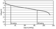
도 3은 C/3의 방전율에서 4.5 V로부터 2 V까지의 방전에 대한 비용량의 함수로써 전압에 대한 도이다. 그것은 사이클링을 위한 선택된 전압창(voltage window)에 대해 이용할 수 있는 용량을 대략적으로 평가하는데 이용될 수 있다.
도 4는 x = 0.5를 가지고, 다른 사이클링 전압창들 사이에서 사이클 되어진 완전히 활성화된 전지에 대한 사이클 수에 따른 비방전 용량을 나타낸 도이다.
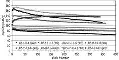
도 5는 x = 0.3를 가지고, 다른 사이클링 전압창들 사이에서 사이클 되어진 활성화된 전지에 대한 사이클 수에 따른 비방전 용량을 나타낸 도이다.
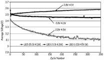
도 6은 x = 0.5를 가지고, 각각, 4.5 V와 2.0 V 사이 또는 4.3 V와 2.8 V 사이 또는 4.1 V로 부터 2.8 V 사이에서 사이클되어진 활성화된 전지에 대한 사이클 수에 따른 평균 방전 전압을 나타낸 도이다.
도 7은 x = 0.3를 가지고, 각각, 4.5 V와 2.0 V 사이 또는 4.2 V와 3.3 V 사이 또는 4.2 V로 부터 2.5 V 사이에서 사이클되어진 활성화된 전지에 대한 사이클 수에 따른 평균 방전 전압을 나타낸 도이다.
도 8은 x = 0.3를 가지고, 4.2 V와 2.5 V 사이에서 사이클되어진 활성화된 전지와 비활성화된 전지에 대한 사이클 수에 따른 비방전용량을 나타낸 도이다. 그 비활성화된 전지는 500 번째 사이클의 충전단계 동안 5.4 V로 충전되었다.
도 9는 각각, x = 0.5 또는 x = 0.3 또는 x = 0.2를 가지고, 4.2 V 이하로 부터 2.0 V이상에서 방전 되어진 활성화된 전지들에 대한 사이클 수에 따른 평균 방전 전압을 나타낸 도이다.
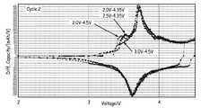
도 10은 x = 0.2를 가지고, 각각, 4.5 V와 3.0 V 사이 또는 4.5 V와 2.0 V 사이 또는 4.35 V와 3.5 V 사이 또는 4.35 V와 2.0 V 사이에서 사이클되어진 활성화된 전지에 대한 2번째 사이클에서의 미분 용량(differential capacity)을 나타낸 도이다.
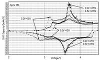
도 11은 x = 0.2를 가지고, 각각, 4.5 V와 3.0 V 사이 또는 4.5 V와 2.0 V 사이 또는 4.35 V로 부터 3.5 V 또는 4.35 V로 부터 2.0 V 사이에서 사이클되어진, 활성화된 전지에 대한 150번째 사이클에서의 미분 용량(differential capacity)을 나타낸 도이다.
도 12는 x = 0.3를 가지고, 4.4 V이하의 상한 사이클링 전압과 2.5 V이상의 하한 사이클링 전압인 다른 사이클링 전압창들 사이에서 사이클되어진, 부분적으로 활성화된 전지와 비활성화된 전지에 대한 사이클 수에 따른 비방전용량을 나타낸 도이다.
도 13a는 x = 0.3를 가지고, 4.5 V와 2.0 V 사이에서 사이클되어진 활성화된 파우치 셀 전지들에 대한 방전 용량과 평균 방전 전압을 나타낸 도이다.
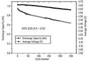
도 13b는 x = 0.3를 가지고, 4.1 V와 3.15 V 사이에서 사이클되어진 활성화된 파우치 셀 전지들에 대한 방전 용량과 평균 방전 전압을 나타낸 도이다.
도 14는 x = 0.3를 가지고, 각각, 4.5 V와 2.0 V 사이 또는, 4.1 V와 3.15 V 사이에서 사이클되어진 2번째, 50번째, 200번째 및 250번째 사이클에서의 활성화된 파우치 셀 전지들에 대한 미분 용량(differential capacity)을 나타낸 도이다.
도 15는 리튬 호일 음극(lithium foil negative electrode)을 가진 활성화된 및 부분적으로 활성화된 셀 전지에 대한 사이클 수에 따른 방전용량을 나타낸 도이다. 둘다 모두, 1C의 충전율 및 2C의 방전율에서, 4.24 V와 2.73 V 사이에서 사이클되어졌다.
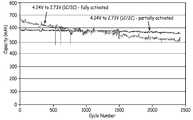
도 16은 활성화된 전지와 부분적으로 활성화된 전지에 대한 사이클 수에 따른 방전용량을 나타낸 도이다. 활성화 된 전지는, 0.75C의 충전율 및 방전율에서, 4.1 V와 3.15 V 사이에서 사이클되어졌다. 부분적으로 활성화 된 전지는, 1C의 충전율 및 2C의 방전율에서, 4.24 V와 2.73 V 사이에서 사이클되어졌다.
도 17은 활성화된 셀 전지와 부분적으로 활성화된 셀 전지에 대한 사이클 수에 따른 평균 방전 전압을 나타낸 도이다. 둘다 모두, 1C의 충전율 및 2C의 방전율에서, 4.24 V와 2.73 V 사이에서 사이클되어졌다.
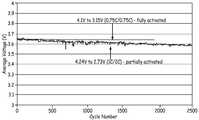
도 18은 활성화된 전지와 부분적으로 활성화된 전지에 대한 사이클 수에 따른 평균 방전 전압을 나타낸 도이다. 활성화된 전지는, 0.75C의 충전율 및 방전율에서, 4.1 V와 3.15 V 사이에서 사이클되어졌다. 부분적으로 활성화 된 전지는, 1C의 충전율 및 2C의 방전율에서, 4.24 V와 2.73 V 사이에서 사이클되어졌다.1 is a schematic diagram of a cell structure separated from a container.
2 is a schematic diagram of a pouch battery.
3 is a plot of voltage as a function of specific capacity for discharge from 4.5 V to 2 V at a discharge rate of C / 3. It can be used to roughly evaluate the available capacity for the selected voltage window for cycling.
4 shows the specific discharge capacity according to the number of cycles for a fully activated battery having x = 0.5 and cycled between different cycling voltage windows.
5 is a diagram showing the specific discharge capacity according to the number of cycles for an activated battery having x = 0.3 and cycled between different cycling voltage windows.
6 shows the average discharge voltage according to the number of cycles for an activated cell having x = 0.5 and cycled between 4.5 V and 2.0 V or between 4.3 V and 2.8 V or between 4.1 V and 2.8 V, respectively. to be.
7 shows the average discharge voltage according to the number of cycles for an activated cell having x = 0.3 and cycled between 4.5 V and 2.0 V or between 4.2 V and 3.3 V or between 4.2 V and 2.5 V, respectively. to be.
8 is a diagram showing the specific discharge capacity according to the number of cycles for an activated cell and an inactivated cell cycled between 4.2 V and 2.5 V with x = 0.3. The deactivated cell was charged to 5.4 V during the 500th cycle of charge.
9 is a diagram showing an average discharge voltage according to the number of cycles for activated batteries having x = 0.5 or x = 0.3 or x = 0.2, and discharged from 4.2 V or less to 2.0 V or more, respectively.
FIG. 10 shows in a second cycle for an activated cell having x = 0.2 and cycled between 4.5 V and 3.0 V or between 4.5 V and 2.0 V or between 4.35 V and 3.5 V or between 4.35 V and 2.0 V, respectively. Is a diagram showing the differential capacity of.
FIG. 11 shows the 150 th time for an activated cell with x = 0.2, cycled between 4.5 V and 3.0 V or between 4.5 V and 2.0 V or between 4.35 V and 3.5 V or from 4.35 V to 2.0 V, respectively. It is a figure which shows the differential capacity in a cycle.
12 shows non-discharge according to the number of cycles for partially activated and deactivated cells, with x = 0.3, cycled between the upper cycling voltages below 4.4 V and the other cycling voltage windows being lower cycling voltages above 2.5 V. FIG. Figure shows capacity.
13A is a diagram showing the discharge capacity and average discharge voltage for activated pouch cell batteries cycled between 4.5 V and 2.0 V with x = 0.3.
FIG. 13B shows the discharge capacity and average discharge voltage for activated pouch cell batteries having x = 0.3 and cycled between 4.1 V and 3.15 V. FIG.
FIG. 14 shows activated pouch cell cells at 2nd, 50th, 200th and 250th cycles with x = 0.3 and cycled between 4.5 V and 2.0 V, or between 4.1 V and 3.15 V, respectively. The figure which shows the differential capacity.
FIG. 15 shows the discharge capacity according to the number of cycles for an activated and partially activated cell cell with a lithium foil negative electrode. Both cycled between 4.24 V and 2.73 V at a charge rate of 1 C and a discharge rate of 2 C.
FIG. 16 is a diagram showing discharge capacity according to the number of cycles for an activated battery and a partially activated battery. The activated cell was cycled between 4.1 V and 3.15 V at a charge and discharge rate of 0.75 C. The partially activated cell was cycled between 4.24 V and 2.73 V at a charge rate of 1C and a discharge rate of 2C.
17 is a diagram showing an average discharge voltage according to the number of cycles for an activated cell battery and a partially activated cell battery. Both cycled between 4.24 V and 2.73 V at a charge rate of 1 C and a discharge rate of 2 C.
18 is a diagram showing an average discharge voltage according to the number of cycles for an activated battery and a partially activated battery. The activated cell was cycled between 4.1 V and 3.15 V at a charge and discharge rate of 0.75C. The partially activated cell was cycled between 4.24 V and 2.73 V at a charge rate of 1C and a discharge rate of 2C.
고용량 리튬이 풍부한 금속 산화물의 사이클링을 제공하기 위한 방법이 개발되어 왔다. 그것은 캐소드 활물질들의 잠재적인 고용량의 상당한 분율을 이용하고, 매우 뛰어난 사이클링 안정성을 제공한다. 상대적으로 새로운 종류의 리튬이 풍부한 혼합된 금속 망간 산화물 조성은 높은 충전 전압에서 사이클링에 있어서 매우 높은 용량을 보일 수 있다. 특별히 흥미있는 리튬이 풍부한 금속 산화물은 합성시 층-층 다중 상 물질을 형성하는 것으로 보인다. 리튬이 풍부한 금속 산화물이 적절한 수준의 사이클링에 대해 높은 용량을 보일 수 있지만, 약간의 응용에 있어서는, 매우 긴 사이클링 안정도를 가지는 것이 바람직하다. 고전압 사이클링 동안, 리튬이 풍부한 금속 산화물의 비가역적 반응의 이해는 매우 안정한 장기 사이클링을 얻을 수 있고, 이용할 수 있는 용량의 상당한 부분을 접근할 수 있음을 발견하였다. 긴 사이클링 안정도는 용량 및 평균 전압에 의하여 달성될 수 있고, 어떤 응용에 대해서도 바람직한 에너지 출력을 제공하는 것이 중요하다. 특히, 리튬이 풍부한 금속 산화물로 형성된 전지들은 리튬이 풍부한 물질을 활성화 시키기 위해 적어도 약 90% 충전 상태(SOC) 또는 일반적으로 약 4.45V의 전압으로 충전하여 형성될 수 있다, 그리고 나서 활성 물질의 활성화에 기인한 용량의 더 큰 부분을 접근하는 동안 사이클링을 안정화 하기 위해서 약 4.2V 이하의 전압처럼 더 낮은 충전 전압을 가지고 사이클된다. 대안적이거나 추가적인 실시예들에서, 전지는 약 4.225V 내지 약 4.45V 까지의 충전 전압으로 사이클되어질 수 있고, 리튬이 풍부한 활물질을 점차적으로 활성화시켜 사이클링에 이용할 수 있는 더 높은 전압 상을 만든다. 유사하게, 전지는 리튬이 풍부한 활물질을 부분적으로 활성화시키기 위해서 첫번째 사이클에서 충전될 수 있고, 그때 전압창 범위내에서 같거나 다른 충전 전압에서 사이클된다. 그리고 그것은 사이클링을 저하시키는 금속 산화물 상들을 형성하는 것 없이 물질의 안정한 활성 상을 더욱 점진적으로 활성화시킬 수 있거나 또는 시킬 수 없다. 하기에 개시된 것 처럼, 활성화 및 사이클링에 대한 다양한 변수는 이들 개념들을 근거로 이용될 수 있다.Methods have been developed to provide cycling of high capacity lithium rich metal oxides. It utilizes a significant fraction of the potential high capacity of cathode active materials and provides very good cycling stability. A relatively new class of lithium-rich mixed metal manganese oxide compositions can exhibit very high capacities for cycling at high charge voltages. Of particular interest are lithium-rich metal oxides that appear to form layer-layer multiphase materials in synthesis. Lithium-rich metal oxides may show high capacity for moderate levels of cycling, but for some applications it is desirable to have very long cycling stability. During high voltage cycling, an understanding of the irreversible reaction of lithium rich metal oxides has found that very stable long term cycling can be achieved and a significant portion of the available capacity can be approached. Long cycling stability can be achieved by capacity and average voltage, and it is important to provide the desired energy output for any application. In particular, cells formed of lithium-rich metal oxides may be formed by charging at least about 90% state of charge (SOC) or generally a voltage of about 4.45V to activate the lithium-rich material, then activating the active material Cycles with lower charge voltages, such as voltages below about 4.2V, to stabilize cycling while approaching a larger portion of the capacity due to. In alternative or additional embodiments, the cell can be cycled with a charge voltage from about 4.225V to about 4.45V, gradually activating the lithium rich active material to make a higher voltage phase available for cycling. Similarly, the cell can be charged in the first cycle to partially activate the lithium-rich active material, which is then cycled at the same or different charge voltages within the voltage window range. And it may or may not be able to more gradually activate the stable active phase of the material without forming metal oxide phases that degrade cycling. As disclosed below, various variables for activation and cycling may be used based on these concepts.
양극 활물질의 활성화는 물질의 초기 상들중 하나에 비가역적 변화들을 포함하는 것으로 보인다. 본원에 개시된 것 처럼, 활성화된 상의 안정도는 전지의 계속된 사이클링에 의존한다. 리튬이 풍부한 물질의 활성화는 적당한 전압에서의 초기 충전을 가지고 달성될 수 있고, 적절한 형성 프로토콜이 이용될 수 있다. 부분적 활성화는 리튬이 풍부한 물질의 초기 상들중 하나에서 부분적 상 변화를 유도하기에 충분히 높은 전압까지 초기 충전을 통해 달성될 수 있다. 점진적인 활성화는 비가역적인 생성물 상까지, 초기 상의 반응을 통해 각 사이클에서 적은 양의 상 전환을 포함하는 것으로 보인다. 그 결과, 활물질의 상들의 개선된 조종을 통해서, 합리적인 방전율에서 전지들은 최소한 초기 용량의 80%의 용량을 가진 급격하게 확장된 수의 사이클 동안 사이클될 수 있다. 그러므로, 좋은 용량들과 에너지 출력들을 가진 전지들은 1500 사이클보다 더 큰 바람직한 사이클링을 가지고 형성될 수 있고, 그것은 교통 수단 이용에 적합하다. 전지들이 원하는 동력 출력을 위해 상대적으로 높은 비율에서 잘 사이클될 수 있다는 것을 확인하였다. 양극 활물질의 안정성은 천번 이상의 사이클링 동안 전지을 사이클링한 후의 평가를 근거로 확인되었고, 매우 적은 수준의 망간이 음극에서 발견된다는 것을 알아내었다. 그것은 수많은 사이클 후에도, 오직 적은 양의 망간들이 양극으로 부터 전해질 속으로 분해된다는 것을 나타낸다.Activation of the positive electrode active material appears to include irreversible changes in one of the initial phases of the material. As disclosed herein, the stability of the activated phase depends on the continued cycling of the cell. Activation of the lithium rich material can be achieved with an initial charge at a suitable voltage, and appropriate formation protocols can be used. Partial activation can be achieved through initial charging up to a voltage high enough to induce partial phase changes in one of the initial phases of the lithium rich material. Gradual activation appears to involve a small amount of phase inversion in each cycle through the reaction of the initial phase, up to the irreversible product phase. As a result, through improved steering of the phases of the active material, at reasonable discharge rates the cells can be cycled for a rapidly extended number of cycles with a capacity of at least 80% of the initial capacity. Therefore, batteries with good capacities and energy outputs can be formed with desirable cycling greater than 1500 cycles, which is suitable for transportation use. It was found that the cells could cycle well at a relatively high rate for the desired power output. The stability of the positive electrode active material was confirmed based on the evaluation after cycling the cell for more than one thousand cycles and found that very low levels of manganese were found in the negative electrode. It indicates that even after numerous cycles, only a small amount of manganese decomposes from the anode into the electrolyte.
층-층 리튬이 풍부한 혼합된 금속 산화물은 큰 전압 범위에서 사이클될 때, 높은 용량 성능을 제공하는 것으로 밝혀졌다. 층-층 리튬이 풍부한 금속 산화물은 좋은 사이클링 능력, 높은 비용량, 높은 총 용량, 상대적으로 높은 평균 전압 및 뛰어난 방전 용량비의 조합을 가지는 전지를 만드는데 이용될 수 있다. 그 결과의 리튬 이온 전지들은 특히 고에너지 응용들에 대해 개선된 전력원으로서 이용될 수 있다. 전기 자동차, 플러그인 하이브리드 전기 자동차 등과 같은, 어떤 응용들에 대해서는 전지들은 큰 원가 인자를 구성하고, 생성물의 효율을 위해, 교통 수단에서 이용되는 전지들은 일반적으로 지나친 성능 저하 없이도 수천번의 사이클같은 오랜 시간 동안 지속되는 것이 바람직하다. 양극 물질들은 방전 사이클에 대해 상대적으로 높은 평균 전압을 나타내어, 전지가 높은 비용량과 함께 높은 에너지 출력을 가질 수 있다. 그 활물질들은 비가역적 용량 손실에서의 감소와 비용량에서의 증가뿐만 아니라, 사이클링에서의 개선을 제공하기 위해 적절한 코팅을 가질 수 있다. 가능성이 있는 결과들이 이 물질들을 위해 제시되어 왔지만, 본원에서 개시된 것 처럼, 이 물질들에 대한 성능에서의 상당한 향상이 더 넓은 범위의 상업적 응용을 위해 매우 바람직할 수 있다.Layered-layer lithium-rich mixed metal oxides have been found to provide high capacity performance when cycled over large voltage ranges. Layer-layer lithium-rich metal oxides can be used to make batteries with a combination of good cycling capability, high specific capacity, high total capacity, relatively high average voltage and excellent discharge capacity ratio. The resulting lithium ion batteries can be used as an improved power source, especially for high energy applications. For some applications, such as electric vehicles, plug-in hybrid electric vehicles, etc., batteries constitute a large cost factor, and for the efficiency of the product, batteries used in transportation are typically used for long periods of time, such as thousands of cycles, without excessive performance degradation. It is desirable to last. The positive electrode materials exhibit a relatively high average voltage over the discharge cycle, such that the cell can have a high energy output with high specific capacity. The active materials may have a suitable coating to provide an improvement in cycling as well as a reduction in irreversible capacity loss and an increase in specific amount. Possible results have been presented for these materials, but as disclosed herein, significant improvements in performance on these materials may be highly desirable for a wider range of commercial applications.
본원에 개시된 전지들은 비수성 전해질 용액이 리튬 이온을 포함하는 리튬 이온 전지들이다. 2차 리튬 이온 전지들에서, 충전 동안, 산화는 캐소드(양극)에서 발생하고, 리튬 이온들은 추출되고 전자들은 방출된다. 방전 동안, 환원은 캐소드에서 발생하고, 리튬 이온들은 삽입되고 전자들은 소비된다. 일반적으로, 전지들은 양극 물질속에 리튬 이온들을 가지고 형성되며, 방전을 위한 전지를 준비하기 위해 전지의 초기 충전은 양극 물질에 있는 리튬의 상당 부분을 음극 물질에 이전한다. 특별히 명시하지 않는한, 본원에서 참조하는 성능 값은 실내 온도에서이다.The batteries disclosed herein are lithium ion batteries in which the nonaqueous electrolyte solution comprises lithium ions. In secondary lithium ion batteries, during charging, oxidation occurs at the cathode (anode), lithium ions are extracted and electrons are released. During discharge, reduction occurs at the cathode, lithium ions are inserted and electrons are consumed. Generally, cells are formed with lithium ions in the positive electrode material, and the initial charging of the cell transfers a significant portion of the lithium in the positive electrode material to the negative electrode material to prepare the cell for discharge. Unless otherwise specified, the performance values referenced herein are at room temperature.
층간 삽입 기반 양극 활물질을 갖는 대응 전지가 사용될 때, 격자로 부터 리튬 이온의 층간 삽입 및 방출은 전기활성 물질의 결정질 격자의 변화를 유도한다. 이들 변화가 본질적으로 가역적이기만 하면, 물질의 용량은 사이클링에 따라 그다지 변화하지 않는다. 그러나, 활물질의 용량은 다양한 정도로 사이클링에 의해 감소되는 것으로 관찰된다. 따라서, 다수의 사이클 후에, 전지의 성능은 허용 가능한 값 미만으로 강하되고, 전지가 교체된다. 또한, 전지의 첫번째 사이클에서, 일반적으로 후속의 사이클에서 사이클 용량 손실당 상당히 더 높은 비가역적 용량 손실이 존재한다. 비가역적 용량 손실은 새로운 전지의 충전 용량과 첫번째 방전 용량 사이의 차이이다. 그 비가역적 용량 손실은 용량, 에너지와 셀에 대한 전력에서의 상응하는 감소를 초래한다. 그 비가역적 용량 손실은 일반적으로 전지 물질의 초기 충전-방전 사이클 동안 변화하는것으로 간주될 수 있고, 일반적으로, 캐소드와 애노드 양쪽에서 발생할 수 있다.When a corresponding cell with an intercalation-based positive electrode active material is used, intercalation and release of lithium ions from the lattice leads to a change in the crystalline lattice of the electroactive material. As long as these changes are inherently reversible, the capacity of the material does not change very much with cycling. However, the capacity of the active material is observed to be reduced by cycling to varying degrees. Thus, after many cycles, the battery's performance drops below an acceptable value, and the battery is replaced. In addition, in the first cycle of the cell, there is generally a significantly higher irreversible capacity loss per cycle capacity loss in subsequent cycles. The irreversible capacity loss is the difference between the charge capacity of the new cell and the first discharge capacity. The irreversible capacity loss results in a corresponding reduction in capacity, energy and power to the cell. The irreversible capacity loss can generally be considered to change during the initial charge-discharge cycle of the cell material, and can generally occur at both the cathode and the anode.
단어 "원소"는 주기율표의 일원으로 언급되는 바와 같이 통상적인 방식으로 본원에 사용되고 있고, 원소는 원소가 조성으로 존재하는 경우 적절한 산화 상태를 가지며, 오직 원소 형태로 존재하는 것으로 언급되는 경우에만 원소가 이의 원소 형태 M0로 존재한다. 따라서, 금속 원소는 일반적으로 단지 그 원소 상태 또는 금속의 원소 형태의 대응 합금의 금속 상태에 있다. 달리 말하면, 금속 합금 이외의 금속 산화물 또는 다른 금속 조성은 일반적으로 금속이 아니다.The word "element" is used herein in a conventional manner, as referred to as a member of the periodic table, and the element has a suitable oxidation state when the element is present in composition, and only when the element is mentioned as present in elemental form It exists in its elemental form M0 . Thus, the metal element is generally only in its elemental state or in the metal state of the corresponding alloy in its elemental form. In other words, metal oxides or other metal compositions other than metal alloys are generally not metals.
리튬 이온 전지는 기준의 균일한 전기 활성 리튬 금속 산화물 조성에 비해서 리튬이 풍부한 양극 활물질을 사용할 수 있다. 관심있는 리튬이 풍부한 양극 활물질의 종류는 대체로 화학식(1) 에 의해 표현될 수 있으며:The lithium ion battery may use a lithium-rich positive electrode active material as compared to the standard uniform electroactive lithium metal oxide composition. The kind of lithium-rich positive electrode active material of interest can generally be represented by formula (1):
Li1+bNiαMnβCoγAδO2-zFz(1)Li1 + b Niα Mnβ Coγ Aδ O2-z Fz (1)
여기서 b는 약 0.01 내지 약 0.3 이고, α는 0 내지 약 0.4이고, β는 약 0.2 내지 약 0.65이고, γ는 약 0 내지 약 0.46이고, δ는 약 0.001 내지 약 0.15이고, z는 0 내지 약 0.2이고, α및 γ가 모두 0이 아닌 조건을 전제로 하며, 여기서 A는 니켈(Ni), 망간(Mn) 및 코발트(Co)와는 별개의 금속 또는 이의 조합이다. 원소 A 및 F(플루오르)는 각각 임의의 양이온 및 음이온 도펀트이다. 원소 A는, 예를 들어, 마그네슘(Mg), 스트론튬(Sr), 바륨(Ba), 카드뮴(Cd), 아연(Zn),알루미늄(Al), 갈륨(Ga), 붕소(B), 지르코늄(Zr), 티타늄(Ti), 칼슘(Ca), 세륨(Ce), 이트륨(Y), 니오븀(Nb), 크롬(Cr), 철(Fe), 바나듐(V) 또는 이들의 조합일 수 있다. 향상된 성능을 달성하기 위한 리튬이 풍부한 금속 산화물 내의 플루오르 도펀트의 사용은, 본원에 참조로 포함된 "높은 비용량을 갖는 플루오르가 도핑된 리튬이 풍부한 금속 산화물 양극 전지 물질 및 해당 전지"라는 쿠마르(Kumar)의 공개된 미국 특허 출원 2010/0086854 에 개시되어 있다.Wherein b is about 0.01 to about 0.3, α is 0 to about 0.4, β is about 0.2 to about 0.65, γ is about 0 to about 0.46, δ is about 0.001 to about 0.15, and z is 0 to about 0.2, and α and γ are both nonzero, where A is a metal or combination thereof separate from nickel (Ni), manganese (Mn) and cobalt (Co). Elements A and F (fluor) are each an optional cation and anionic dopant. Element A is, for example, magnesium (Mg), strontium (Sr), barium (Ba), cadmium (Cd), zinc (Zn), aluminum (Al), gallium (Ga), boron (B), zirconium ( Zr), titanium (Ti), calcium (Ca), cerium (Ce), yttrium (Y), niobium (Nb), chromium (Cr), iron (Fe), vanadium (V), or a combination thereof. The use of fluorine dopants in lithium rich metal oxides to achieve improved performance has been described in Kumar, "High Specific Amount Fluorine Doped Lithium Rich Metal Oxide Bipolar Cell Materials and Corresponding Cells", incorporated herein by reference. Is disclosed in published US patent application 2010/0086854.
일부 실시예에서, 적절하게 형성된 리튬이 풍부한 리튬 금속 산화물은 복합 결정 구조체를 갖는 것으로 생각된다. 예를 들어, 리튬 풍부한 물질의 일부 실시예에서, 층상화된 Li2MO3 물질은 비록 관심있는 특정 조성이 망간 양이온을 적절한 산화 상태를 갖는 다른 전이 금속 양이온으로 대체할지라도, 층상화된 LiM'O2 물질 성분(기준 구조는 M과 M'을 망간으로 가진다)과 구조적으로 일체화될 수 있다. 일부 실시예에서, 양극 전극 물질은 x Li2MO3·(1-x)LiM'O2 로서 2성분 표기법으로 나타내 수 있고, 여기서 M'는 적어도 하나의 양이온이 망간 양이온 또는 니켈 양이온인 +3가의 평균 원자가를 갖는 하나 이상의 금속 양이온이고, 여기서 M은 +4의 평균 원자가를 갖는 하나 이상의 금속 양이온이다. 일반적으로, 특히 흥미있는 조성으로서, M은 Mn으로 간주될 수 있다. 조성의 일반적인 종류는, 예를 들어, 발명의 명칭이 "리튬 셀 및 전지용 리튬 금속 산화물 전극(Lithium Metal Oxide Electrodes for Lithium Cells and Batteries)" 인 태커레이(Thackeray) 등에 의한 미국 특허 제 6,680,143 ('143 특허)와 발명의 명칭이 "고비용량과 뛰어난 사이클링을 갖는 층-층 리튬이 풍부한 복합체 금속 산화물(Layer-Layer Lithium Rich Complex Metal Oxides With High Specific Capacity and Excellent Cycling)" 인 로페즈(Lopez) 등에 의한 공개된 미국 특허 출원 2011/0052981A ('981 출원)에 더 기재되고, 이들은 모두 본원에 의해 참조로서 포함되어 있다. 단일 성분 명명법과 2성분 명명법에 표현된 조성은 상호 관련될 수 있다. 특히, 상기 화학식 (1)에 있는 b+α+β+γ+δ 가 대략적으로 1이라면, z=0으로 단순히 추정하면 그 물질은 식 x·Li2MnO3·(1-x)LiNiuMnvCowAyO2 로 표시되는 적층 물질일 수 있다. 복합 물질을 갖는 전지의 충전에 대해, 조성의 리튬 망간 산화물(Li2MnO3) 성분은 반응식 (2)에 나타낸 바와 같이 반응을 통해 두 개의 리튬 이온의 관련된 방출과 산소 분자(molecular oxygen)를 방출할 수 있다.In some examples, suitably formed lithium-rich lithium metal oxides are thought to have a composite crystal structure. For example, in some embodiments of lithium rich materials, the layered Li2 MO3 material may be layered LiM ', even if the particular composition of interest replaces the manganese cation with another transition metal cation having an appropriate oxidation state. It can be structurally integrated with an O2 material component (the reference structure has M and M 'as manganese). In some embodiments, the positive electrode material may be represented in two-component notation as x Li2 MO3 · (1-x) LiM'O2 , where M 'is +3 wherein at least one cation is a manganese cation or a nickel cation. At least one metal cation having a mean average valence, where M is at least one metal cation having an average valence of +4. In general, as a composition of particular interest, M can be regarded as Mn. A general kind of composition is described, for example, in US Pat. No. 6,680,143 ('143) by Thackeray et al., Entitled "Lithium Metal Oxide Electrodes for Lithium Cells and Batteries". Patent) and the invention by Lopez et al., "Layer-Layer Lithium Rich Complex Metal Oxides With High Specific Capacity and Excellent Cycling". US Patent Application 2011 / 0052981A (the '981 Application), which are incorporated herein by reference in their entirety. Compositions expressed in single-component nomenclature and two-component nomenclature may be interrelated. In particular, if b + α + β + γ + δ in the formula (1) is approximately 1, simply estimating z = 0, the material is the formula x Li2 MnO3 (1-x) LiNiu MnIt may be a laminated material represented byv Cow Ay O2 . For charging a cell with a composite material, the lithium manganese oxide (Li2 MnO3 ) component of the composition releases the related release of two lithium ions and the molecular oxygen through the reaction as shown in Scheme (2). can do.
Li2MnO3-> (MnO2)+ 2Li+ +2e- + 1/2O2(2)Li 2 MnO 3 -> (MnO 2) + 2Li + + 2e - + 1 / 2O 2 (2)
방전시, (MnO2) 조성은 단일 리튬 이온과 단일 전자를 차지하여 LiMnO2를 형성함으로써 초기 충전시 물질의 비가역적 반응으로 인해 용량이 전반적으로 상당히 감소하게 된다. 생성물의 조성은 (MnO2)로 쓰여졌는데, 그것은 이 물질이 무엇인가가 완전히 명확하지 않기 때문이다. 만일 (MnO2)가 정확히 MnO2 라면, 반응식 (2)는 균형이 잡히게 되나, 금속의 환원에 따른 산소의 발생이 관찰되지만 그 반응이 정확한 반응인지는 명확하지 않다. 하기에 논의된 바와 같이, 증거는 반응식 (2)가 4.4 볼트 이상의 전압에서 효율적으로 발생한다는 것을 시사한다. 따라서, 리튬이 풍부한 층-층 물질로 인해, 4.2 볼트 이상의 첫번째 사이클의 충전시, 고용량 물질 내의 Li2MnO3성분의 분해는 산소 손실 및 양극 활물질로 기인되는 상당한 비가역적 용량 손실로 이어질 수 있다. 원칙적으로 물질은 Li2MnO3-> MnO2+ Li2O의 분해 반응과 같은 초기 충전단계와 일치하는 다른 비가역적 반응들을 수행할 수 있다. 이러한 분해 반응은, 초기 충전시 측정되나 전자가 생성되지 않기 때문에, 측정된 비가역적 용량 손실을 초래하지 않지만, 불활성 리튬 산화물을 형성하는 이러한 반응은 물질의 특정 중량에 대한 이론 용량과 관련된 가역적 용량의 손실을 야기할 수 있다. 중요한 추가적인 증거들이 본원에 제시되어 있지만, 활물질을 포함하는 초기 반응이 완전히 이해된 것은 아니다. 예를 들어, 하기에 제시된 증거는 오직 낮은 수준의 망간들(manganese)이 전해질 속에서 분해되어 음극으로 이동하는 것과, 2000 번의 사이클 후에 음극은 망간들의 1 wt% 이하를 가진다는 것을 보여준다. 미분 용량(differential capacity) 결과들은 사이클링 데이타에서 발견된 양극의 안정화와 일치한다.Upon discharge, the (MnO2 ) composition occupies a single lithium ion and single electron to form LiMnO2 , resulting in a significant overall decrease in capacity due to the irreversible reaction of the material at initial charge. The composition of the product is written as (MnO2 ) because it is not entirely clear what this material is. If (MnO2 ) is exactly MnO2 , Scheme (2) is balanced, but the generation of oxygen following the reduction of the metal is observed, but it is not clear whether the reaction is an exact reaction. As discussed below, the evidence suggests that Scheme (2) occurs efficiently at voltages above 4.4 volts. Thus, due to the lithium-rich layer-layer material, upon charge of the first cycle of 4.2 volts or more, decomposition of the Li2 MnO3 component in the high capacity material can lead to oxygen loss and significant irreversible capacity loss due to the positive electrode active material. In principle, the material can carry out other irreversible reactions consistent with the initial charging stage, such as the decomposition reaction of Li2 MnO3- > MnO2 + Li2 O. This decomposition reaction does not result in a measured irreversible capacity loss because it is measured at the initial charge but no electrons are produced, but this reaction, which forms inert lithium oxide, is related to the theoretical capacity for the specific weight of the material. May cause loss. Although important additional evidence is presented herein, the initial reaction involving the active material is not fully understood. For example, the evidence presented below shows that only low levels of manganese decompose in the electrolyte and migrate to the cathode, and after 2000 cycles the cathode has less than 1 wt% of manganese. Differential capacity results are consistent with the stabilization of the anode found in the cycling data.
본원에서 제시된 식들은 합성에서 출발 물질의 몰랄량 (molar quantities)을 기준으로 하여, 정확하게 결정될 수 있다. 일반적으로 복수의 금속 양이온에 관해서는, 생성물의 조성으로부터 금속들의 손실을 초래하는 알려진 중요한 경로는 없지만, 최종 물질속으로 양적으로 포함되는 것으로 생각된다. 물론, 많은 금속들이 복수의 산화수를 가지며, 이것은 전지에 대한 그들의 활성과 관련된다. 복수의 산화수와 복수의 금속들의 존재때문에, 산소에 대한 정확한 화학양론(stoichiometry)은, 당해 기술분야의 관행처럼, 일반적으로 반응물 금속들의 결정 구조, 전기화학적 성능 및 비율들을 기초로 하여 오직 대략적으로 평가되어 진다. 그러나, 결정 구조를 기초로 해서, 산소에 대한 전체적인 화학양론은 합리적으로 평가되어진다. 이 단락에서 논의된 모든 프로토콜들(protocols)과 관련된 이슈들은 당해 기술 분야에서 일상적인 것이고, 이런 이슈들에 대해서는 오랫동안 확립된 방법이다.The formulas presented herein can be accurately determined based on the molar quantities of starting material in the synthesis. In general, as regards the plurality of metal cations, there is no known important route that results in the loss of metals from the composition of the product, but it is believed to be included in quantity into the final material. Of course, many metals have a plurality of oxidation numbers, which are related to their activity on the cell. Because of the presence of a plurality of oxides and a plurality of metals, the exact stoichiometry for oxygen is generally only estimated based on the crystal structure, electrochemical performance and ratios of the reactant metals, as is common practice in the art. It is done. However, based on the crystal structure, the overall stoichiometry for oxygen can be reasonably evaluated. Issues relating to all protocols discussed in this paragraph are common in the art and are a long established method for these issues.
편의상, 첫번째 사이클은 전지물질에 두드러진 비가역적 변화들을 포함하는 형성 사이클로 나타낼 수 있다. 고전압에서 양극 활물질의 활성화를 위하여, 바람직한 다중 단계 형성 프로토콜(multiple step formation protocol)이 개발되어왔고, 이는 발명의 명칭이 "고전압 전지 형성 프로토콜과 바람직한 장기 사이클링 수행을 위한 충전과 방전의 조절(High Voltage Bettery Formation Protocols and Control of Charging and Discharging for Desirable Long Term Cycling Performance)" 인 아미루딘(Amiruddin) 등의 계류중인 미국 특허 출원 12/732,520 (이하 '520 출원) 에 설명되어 있고, 본 명세서에 참조로서 포함되어 있다. 첫번째 사이클 후에, 리튬이 풍부한 금속 산화물들은 고전압에서 사이클링한 결과로써 추가적인 구조 변화들을 하는것으로 밝혀졌다. 특히, 고전압이 충전될 때, 그 물질은 더욱 점진적이지만, 계속적으로 구조에서 비가역적 변화를 하는 것으로 밝혀졌다. 이론에 의해 제한 되어질 것을 원하지 않지만, 이런 계속적인 변화는 (MnO2)로써 위에 언급된 물질과 관련되어 있는 것으로 보인다. 만일 사이클링이 고전압에서 계속된다면, 그 물질은 전해질속으로 전이 금속들의 분해와 관련되어 불안정한 저전압 물질로 변화하는 것으로 관찰된다. 전해질속으로 전이 금속들이 분해됨으로써, 용량은 손실되고, 그것은 리튬을 사이클하기 위해 이용되어질 더 적은 양의 물질과 일치한다.For convenience, the first cycle can be represented by a formation cycle that includes noticeable irreversible changes in cell material. For activation of the positive electrode active material at high voltage, a preferred multiple step formation protocol has been developed, which is called "high voltage cell formation protocol and control of charge and discharge for performing long term cycling (High Voltage). Amiruddin et al., A Betterudd Formation Protocols and Control of Charging and Discharging for Desirable Long Term Cycling Performance. " It is. After the first cycle, lithium-rich metal oxides were found to make additional structural changes as a result of cycling at high voltages. In particular, when the high voltage is charged, the material is found to be more gradual, but continually irreversible change in structure. While not wishing to be bound by theory, this continuous change appears to be related to the materials mentioned above as (MnO2 ). If cycling continues at high voltage, the material is observed to change into an unstable low voltage material associated with the decomposition of transition metals into the electrolyte. As the transition metals break down into the electrolyte, capacity is lost, which is consistent with the lower amount of material that will be used to cycle lithium.
전지의 충전 및 방전 동안, 전압은 전지의 특정 전하 상태를 참조하는데 사용될 수 있다. 이 기술분야에서, 대안으로 전지의 충전 상태(SOC)를 참조하는 것은 일상적인 것이고, 전지에 남아 있는 기준 용량(reference capacity)의 퍼센트를 참조한다. 기준 용량을 정하는데 있어서 유연성이 있을 수 있으므로, SOC는 어떤 의미에서 덜 정확할 것이다. 전하 상태의 상한은 전지의 초기 조립시 본래의 양극 활물질의 리튬을 완전히 추출하기 위해 필요한 전하이고, 약 5V를 요구할 수 있다. 전지의 완전히 추출될 수 있는 용량은, 전지 사용의 나중 사이클에서 최대치 미만이다. 사이클링 동안, 완전한 SOC의 선택된 부분은 사이클링 생명을 향상시키기 위해 이용될 수 있고, 전지 화학을 기초로해서 SOC의 부분들을 선택하는 것이 바람직한 방법들이고, 본원에 설명되어 있다.During charging and discharging of the cell, the voltage can be used to refer to the specific charge state of the cell. In the art, alternatively referencing the state of charge (SOC) of a cell is routine and refers to the percentage of reference capacity remaining in the cell. SOC will be less accurate in some sense, as there may be flexibility in setting the reference dose. The upper limit of the charge state is the charge required to completely extract the lithium of the original positive electrode active material during initial assembly of the battery, and may require about 5V. The fully extractable capacity of the cell is below the maximum in later cycles of battery use. During cycling, selected portions of the complete SOC can be used to enhance cycling life, and it is preferred methods to select portions of the SOC based on cell chemistry and are described herein.
음극과 관련된 보충 리튬이 전해질 속으로 금속 분해와 관련된 용량의 손실을 안정화 하는 것을 도울 수 있다는 것이 밝혀졌다. 따라서, 보충 리튬은 상당한 수의 사이클에서 리튬이 풍부한 금속 산화물의 용량에 대한 사이클링을 안정화 시킬 수 있다. 이 발견은 발명의 명칭이 "보충 리튬을 가진 리튬 이온 전지들(Lithium Ion Batteries With Supplemental Lithium)" 인 아미루딘(Amiruddin) 등의 계류중인 미국 특허 출원 12/938,073 에 더 자세하게 설명되어 있고, 본 명세서에 참조로서 포함되어 있다('073 출원).It has been found that supplemental lithium associated with the negative electrode can help stabilize the loss of capacity associated with metal decomposition into the electrolyte. Thus, supplemental lithium can stabilize cycling over the capacity of lithium rich metal oxides in a significant number of cycles. This finding is described in more detail in pending US patent application Ser. No. 12 / 938,073, entitled Amiruddin et al., Entitled "Lithium Ion Batteries With Supplemental Lithium." Is incorporated by reference (filed '073).
요약하면, 리튬이 풍부한 금속 산화물에 상당한 비가역적 변화들이 첫번째 고전압 충전 사이클 동안 발생한다는 것을 확인하였고, 그것은 산소 분자의 약간의 손실과 이에 따른 금속 산화물 조성에 있어서 비가역적 변화을 포함한다. 고전압 사이클링을 계속함에 따라, 물질의 계속적인 변화가 발생한다. 보충 리튬을 가지지 않은 물질에 있어서, 계속적인 구조 변화는 전해질 속으로의 분해때문에 불안정한 물질을 초래하고, 용량의 점진적인 손실과 평균 전압이 감소되는 결과를 초래한다. 보충 리튬을 가진 경우의 고전압 사이클링에 있어서는, 활물질은 전해질속에서 상대적으로 안정한 물질로 상변화를 경험하나, 더 낮은 사이클링 전압을 가지고, 전지가 사이클됨으로써, 평균 전압이 점차로 감소한다.In summary, it has been found that significant irreversible changes to lithium-rich metal oxides occur during the first high voltage charge cycle, which includes some loss of oxygen molecules and thus an irreversible change in metal oxide composition. As the high voltage cycling continues, a continuous change of material occurs. For materials that do not have supplemental lithium, continuous structural changes result in unstable materials due to decomposition into the electrolyte, resulting in gradual loss of capacity and reduced average voltage. In high voltage cycling with supplemental lithium, the active material undergoes a phase change with a relatively stable material in the electrolyte, but with a lower cycling voltage, as the cell cycles, the average voltage gradually decreases.
이 물질 변화들은 평균 전압뿐만 아니라, 용량에 대해서 놀라울 정도로, 전지의 사이클링을 안정화 시키기 위하여 조작될 수 있다는 것이 밝혀졌다. 특히, 그 물질은 약 4.45V 이상의 전압에서 초기 활성화 충전을 할 수 있다. 그 다음, 활성화 충전은, (MnO2)로써 언급된 물질을 형성하기 위하여 초기물질의 상들 중 하나를 활성화시키는 비가역적인 화학 변화들을 경험하는, 고전압 상(근본적으로 Li2MnO3으로 생각되는)으로부터 리튬을 추출한다. 이 활성화된 상(MnO2)이 고전압까지 확장되지 않은 전압 범위에 대하여 용량과 평균전압에 관해 안정되게 사이클되어질 수 있다는 것이 밝견되었다. 그러나, 계속적으로 더 큰 전압으로 충전된다면 이용할 수 있는 용량보다 덜하겠지만, 용량이 활성화되지 않은 물질에 대해 상응하는 용량보다 더 커지기 때문에, 만일 리튬의 상대적으로 적은 분량이 계속된 충전 단계들 동안 추출된다면, 활성화 사이클 동안 형성된 초기 상은 안정되게 사이클 할 수 있다.It has been found that these material changes can be manipulated to stabilize the cycling of the cell, surprisingly with respect to capacity as well as the average voltage. In particular, the material is capable of initial activation charging at voltages above about 4.45V. The activation charge is then from the high voltage phase (essentially thought to be Li2 MnO3 ), which undergoes irreversible chemical changes that activate one of the phases of the initial material to form the material referred to as (MnO2 ). Lithium is extracted. It has been found that this activated phase (MnO2 ) can be cycled stably with respect to capacity and average voltage over a voltage range that does not extend to high voltage. However, if continuously charged to a higher voltage, it will be less than the available capacity, but if the capacity is greater than the corresponding capacity for the unactivated material, if a relatively small amount of lithium is extracted during subsequent charging steps The initial phase formed during the activation cycle can cycle stably.
매우 놀라운 결과들이 전지의 중간의 초기 충전과 사이클링 동안 상응하는 전압 범위 유지를 통해 얻어질 수 있다. 만일, 전지가 약 4.225V로 부터 4.45V 까지의 전압으로 충전된다면, 초기 물질은 부분적으로 활성화되는 것으로 발견된다. 그 부분적으로 활성화된 물질은 더 큰 사이클링 안정성 조차도 제공할 수 있다. 그 부분적 활성화는 추가적인 점진적 활성화와 결합하거나 또는 결합하지 않을 수도 있다. 단일의, 초기 형성 사이클에 대한 것보다는 오히려 많은 사이클들에 대해, 점진적 활성화를 가지고, 리튬 양극 활물질로의 비가역적 변화들이 점진적으로 발생한다. 점진적 활성화는 일반적으로, 약 4.225 V에서 약 4.45 V까지의 부분적 활성화 범위의 하단부를 커버하는 충전 전압까지 사이클링을 통해서 달성된다. 사이클링에 대한 충전 전압의 값이 더 낮지만, 캐소드 활물질의 이 점진적인 활성화를 기초로, 평균 전압뿐만 아니라 용량은 놀랍게도 전지의 적당한 수의 사이클에 대한 초기 사이클링을 다소 증가시키고, 그 용량은 본질적으로 고르게 된다. 충전 전압, 용량 및 평균 전압 안정기(plateau)의 적절한 선택을 가지고, 용량과 평균 전압은, 초기 용량의 80%까지 떨어지기 전에 수 천번의 사이클에 대해, 본질적으로 안정화 되어질 수 있다. 이것은 좋은 비용량 값을 가지고 달성될 수 있는 놀라울만한 사이클링 성능이다.Very surprising results can be obtained through maintaining the corresponding voltage range during initial charging and cycling of the cell. If the cell is charged to a voltage from about 4.225V to 4.45V, the initial material is found to be partially activated. The partially activated material can provide even greater cycling stability. That partial activation may or may not be combined with additional progressive activation. For many cycles rather than for a single, initial formation cycle, with irreversible activation, irreversible changes to the lithium cathode active material occur gradually. Gradual activation is generally achieved through cycling up to a charging voltage that covers the lower end of the partial activation range from about 4.225 V to about 4.45 V. Although the value of the charge voltage for cycling is lower, based on this gradual activation of the cathode active material, the capacity as well as the average voltage surprisingly slightly increases the initial cycling for a suitable number of cycles of the cell, and the capacity is essentially even do. With proper selection of charge voltage, capacity and average voltage plateau, the capacity and average voltage can be essentially stabilized for thousands of cycles before falling to 80% of the initial capacity. This is an amazing cycling performance that can be achieved with good specific cost values.
그 예들에 있는 전지들은 음극에 흑연질 탄소 활물질을 포함한다. 그러나, 물질들의 조작과 적절한 안정화를 통한 양극 활물질들의 향상된 성능은 리튬을 삽입하거나 합금되는 다른 음극 활물질들까지 확장될 수 있다. 그 전극들은 적절한 전지 포맷으로 조립될 수 있다.The batteries in those examples include a graphite carbon active material at the negative electrode. However, the improved performance of the positive electrode active materials through the manipulation and proper stabilization of the materials can be extended to other negative electrode active materials that incorporate lithium or are alloyed. The electrodes can be assembled in a suitable cell format.
뛰어난 성능 결과들이 활성화된 전지 및 부분적으로 활성화된 전지들 모두에 대하여 수 천번의 사이클들에 대한 장기 사이클링 동안 얻어져 왔다. 특히, 비용량은 최소 약 100 mAh/g 으로 얻어졌다. 사이클링 안정화는 평균 전압뿐만 아니라, 전지 용량에 대하여 얻어졌다. 그 사이클링 안정화는, 교통 수단에 이용되는 것처럼, 특히 장기 성능이 중요한 응용들에 대해 유리할 수 있다.
Excellent performance results have been obtained during long term cycling for thousands of cycles for both activated and partially activated cells. In particular, the specific amount was obtained at least about 100 mAh / g. Cycling stabilization was obtained for the battery capacity as well as the average voltage. The cycling stabilization can be advantageous, especially for applications where long term performance is important, as used in transportation.
리튬 이온 전지들Lithium ion batteries
리튬 이온 전지들은 일반적으로, 양극(positive electrode), 음극(negative electrode), 음극과 양극사이에 존재하는 분리막 및 리튬 이온들로 구성된 비수성 전해액으로 구성된다. 전극은 일반적으로 금속 집전체(metal current collector)와 연관된다. 리튬 이온 전지들은 충전 동안 리튬을 흡수하고, 방전 동안 리튬을 방출하는 음극 활물질을 가진 전지들을 나타낸다. 도 1을 참조하면, 전지(100)은 음극(102), 양극(104) 및 음극(102)와 양극(104)사이의 분리막(106)을 갖는것으로 개략적으로 도시되어 있다. 전지는 적층으로 복수의 양극 및 복수의 음극과 함께 적절하게 배치된 분리막을 포함할 수 있다. 전극과 접촉하는 전해질은 대항하는 극성의 전극 사이에서 분리막을 통해 이온 전도성을 제공한다. 전지는 일반적으로 각각 음극(102) 및 양극(104)와 관련된 집전체(current collector)(108, 110)를 포함한다. 기본적인 전지 구조와 조성이 이 장에서 기재된다.Lithium ion batteries are generally composed of a positive electrode, a negative electrode, a separator between the negative electrode and the positive electrode, and a nonaqueous electrolyte composed of lithium ions. The electrode is generally associated with a metal current collector. Lithium ion batteries represent batteries with a negative active material that absorbs lithium during charging and releases lithium during discharge. Referring to FIG. 1, the
음극 층간삽입/합금 물질의 성질은 전압이 캐소드 및 애노드에서 반쪽 셀 전위 간의 차이 전압이기 때문에 그 결과의 전지 전압에 영향을 미친다. 적당한 음극(애노드) 리튬 층간삽입/합금 조성은, 예를 들면 흑연, 합성 흑연, 코크스, 풀러렌, 다른 흑연질 탄소, 오산화니오브, 주석 합금, 규소, 산화 티탄, 산화 주석, 및 리튬 산화 티탄을 포함할 수 있고, 예컨대 LixTiO2, 0.5<x≤1 또는 Li1+xTi2-xO4, 0≤x≤1/3 이다. 흑연질 탄소와 금속 산화 음극 조성은 층간삽입이나 유사한 과정을 통해서 리튬을 흡수 또는 방출한다. 실리콘과 주석 합금은 리튬을 흡수 또는 방출하기 위해서 리튬 금속과 합금을 형성한다. 추가적인 음극 물질은 발명의 명칭이 "복합 조성, 복합 조성을 갖는 음극 및 대응 전지(Composite Compositions, Negative Electrode with Composite Compositions and Corresponding Batteries.)"인 쿠마르(Kumar)의 공개된 미국 특허 출원 2010/0119942 와 발명의 명칭이 "특정 음극 조성을 갖는 고에너지 리튬 이온 전지(High Energy Lithium Ion Batteries with Particular Negative Electrode Compositions)" 인 쿠마르 등의 미국 특허 출원 2009/0305131 에 기재되어 있고 이들 양 출원은 모두 본 명세서에 참조로서 포함된다. 실리콘 기반의 음극 활물질은 발명의 명칭이 "리튬 이온 전지를 위한 높은 용량의 애노드 물질(High Capacity Anode Materials for Lithium Ion Batteries)" 인 로페즈(Lopez) 등의 2010년 11월 3일에 출원된 공개된 미국 특허 출원 2011/0111294 에 기재되어 있다. 실리콘 산화물 기반의 음극 활물질은 발명의 명칭이 "실리콘 산화물 기반의 리튬 이온 전지를 위한 높은 용량의 애노드 물질(Silicon Oxide Based High Capacity Anode Materials for Lithium Ion Batteries)" 인 뎅(Deng) 등의 2011년 5월 16일에 출원된 동시 계류중인 미국 특허 출원 13/108,708 에 기재되어 있다. 이들 양 출원은 모두 본 명세서에 참조로서 포함되어 있다.The nature of the negative electrode intercalation / alloy material affects the resulting cell voltage because the voltage is the difference voltage between the half cell potentials at the cathode and anode. Suitable anode (anode) lithium intercalation / alloy compositions include, for example, graphite, synthetic graphite, coke, fullerene, other graphite carbon, niobium pentoxide, tin alloys, silicon, titanium oxide, tin oxide, and lithium titanium oxide. For example, Lix TiO2 , 0.5 <x ≦1 or Li1 + x Ti2-x O4 , 0 ≦x ≦ 1/3. Graphite carbon and metal oxide cathode compositions absorb or release lithium through intercalation or similar processes. Silicon and tin alloys form alloys with lithium metal to absorb or release lithium. Additional negative electrode materials are disclosed in the published US patent application 2010/0119942 by Kumar, entitled "Composite Compositions, Negative Electrode with Composite Compositions and Corresponding Batteries." U.S. Patent Application 2009/0305131 to Kumar et al., Entitled "High Energy Lithium Ion Batteries with Particular Negative Electrode Compositions," both of which are incorporated herein by reference. Included. A silicon-based negative active material is disclosed in the application filed on November 3, 2010, by Lopez et al., Entitled “High Capacity Anode Materials for Lithium Ion Batteries”. US patent application 2011/0111294. The silicon oxide based anode active material was named "Dilton," which is named "Silicon Oxide Based High Capacity Anode Materials for Lithium Ion Batteries". Co-pending US patent application Ser. No. 13 / 108,708, filed May 16. Both of these applications are incorporated herein by reference.
양극 활성 조성과 음극 활성 조성은 일반적으로 고분자 바인더에 의해 해당 전극에서 함께 수용되는 분말 조성이다. 바인더는 전해질에 접촉할 때 활성 입자 (active particles)에 이온 전도도를 제공한다. 적절한 고분자 바인더는, 예를 들어, 폴리비닐리딘 플루오라이드(polyvinylidine fluoride), 폴리에틸렌 옥사이드 (polyethylene oxide), 폴리에틸렌(polyethylene), 폴리프로필렌(polypropylene), 폴리테트라플루오르에틸렌 (polytetrafluoroethylene), 폴리아크릴레이트 (polyacrylate), 고무들 (rubbers), 예를 들어, 에틸렌-프로필렌-디엔 모노머 (ethylene-propylene-diene monomer, EPDM) 고무, 또는 스티렌 부타디엔 고무(styrene butadiene ruber, SBR), 이들의 공중합체, 또는 이들의 혼합물을 포함한다. 바인더에 적재되는 입자는 약 80 wt% 이상과 같이 매우 클 수 있다. 전극을 형성하기 위하여, 고분자 용매와 같은 적당한 액체 내에서 분말은 고분자와 혼합될 수 있다. 생성된 페이스트(paste)는 전극 구조로 가압될 수 있다.The positive electrode active composition and the negative electrode active composition are generally powder compositions that are received together at the corresponding electrode by a polymeric binder. The binder provides ionic conductivity to the active particles when in contact with the electrolyte. Suitable polymeric binders are, for example, polyvinylidine fluoride, polyethylene oxide, polyethylene, polypropylene, polytetrafluoroethylene, polyacrylate ), Rubbers such as ethylene-propylene-diene monomer (EPDM) rubber, or styrene butadiene ruber (SBR), copolymers thereof, or copolymers thereof Mixtures. The particles loaded into the binder can be very large, such as at least about 80 wt%. To form the electrode, the powder can be mixed with the polymer in a suitable liquid, such as a polymer solvent. The resulting paste may be pressed into the electrode structure.
양극 조성, 그리고 아마도 음극 조성은, 일반적으로 전기 활성 조성(eletroactive composition)과는 별개인 전기 전도성 분말을 또한 포함한다. 적절한 보충의 전기 전도성 분말은, 예를 들어, 흑연, 카본 블랙, 은 분말과 같은 금속 분말, 스테인레스 강 섬유 등과 같은 금속 섬유 및 이들의 조합을 포함한다. 일반적으로, 양극은 1 wt% 내지 25 wt%, 그리고 또 다른 실시형태에서는 약 2 wt% 내지 15 wt% 의 별개의 전기 전도성 분말을 포함할 수 있다. 본 기술 분야에서 통상의 기술을 가진 자는 상기한 명시적 범위 내에서 전기 전도성 분말 및 고분자 바인더의 양에 대한 추가 범위가 고려될 수 있으며, 본 개시에 포함된다는 것을 인지할 것이다.The positive electrode composition, and possibly the negative electrode composition, also generally includes an electrically conductive powder that is separate from the electroactive composition. Suitable supplemental electrically conductive powders include, for example, metal powders such as graphite, carbon black, silver powders, metal fibers such as stainless steel fibers and the like and combinations thereof. In general, the anode may comprise 1 wt% to 25 wt%, and in yet another embodiment about 2 wt% to 15 wt% of a separate electrically conductive powder. Those skilled in the art will recognize that additional ranges for the amount of electrically conductive powders and polymeric binders may be considered and are included in the present disclosure within the explicit ranges noted above.
일반적으로 전극은 전기 전도성 집전체(current collector)와 관련되어 전극 및 외부 회로 사이의 전자의 흐름을 촉진시킨다. 그 집전체는 금속 호일 또는 금속 격자와 같은 금속을 포함할 수 있다. 일부 실시예에서, 집전체는 니켈, 알루미늄, 스테인리스 강, 구리 등으로 형성될 수 있다. 전극 물질은 집전체 상에 박막으로 형성될 수 있다. 집전체를 갖는 전극 물질은, 예를 들어 오븐에서 건조되어 전극으로부터 용매를 제거할 수 있다. 일부 실시예에서, 집전체 호일, 또는 기타 구조물과 접촉된 건조된 전극 물질은 약 2 내지 10 kg/cm2 (제곱 센티미터 당 킬로그램) 같은 압력을 받을 수 있다.In general, the electrode is associated with an electrically conductive current collector to promote the flow of electrons between the electrode and the external circuit. The current collector may comprise a metal, such as a metal foil or a metal grid. In some embodiments, the current collector may be formed of nickel, aluminum, stainless steel, copper, or the like. The electrode material may be formed in a thin film on the current collector. The electrode material with the current collector can be dried, for example, in an oven to remove the solvent from the electrode. In some embodiments, the dried electrode material in contact with the current collector foil, or other structure, may be subjected to a pressure, such as about 2 to 10 kg / cm2 (kg per square centimeter).
분리막은 양극과 음극사이에 위치한다. 분리막은 두 전극 사이에서 적어도 선택된 이온 전도를 제공하면서 전기적으로 절연된다. 다양한 물질이 절연막으로 사용될 수 있다. 상업적인 분리막 물질은 일반적으로 이온 전도를 가능하게 하는 다공성 시트(porous sheets)인 폴리에틸렌 및/또는 폴리프로필렌과 같은 고분자로 형성된다. 상업적인 고분자 분리막은, 예를 들어, Hoechst Celanese, Charlotte, N.C 사의 Celgard® 계 분리막 물질을 포함한다. 또한, 세라믹-고분자 복합 물질들은 분리막 적용을 위해 개발되었다. 이러한 복합 분리막은 고온에서 안정적일 수 있고, 복합 물질은 화재 위험을 상당히 줄일 수 있다. 분리막 물질용 고분자-세라믹 복합체는, 본원에 참조로 포함된 "전기 분리막, 이의 제조 방법 및 이의 용도" 이라는 제목의 헤니겔(Hennige) 등의 공개된 미국 특허 출원 제 2005/0031942A 호에 더 개시되어 있다. 리튬 이온 전지 분리막용 고분자-세라믹 복합체는 독일의 예보닉 인더스트리즈(Evonik Industries)사의 상표 세파리온(Separion®)하에 판매되고 있다.The separator is located between the anode and the cathode. The separator is electrically insulated while providing at least selected ion conduction between the two electrodes. Various materials can be used as the insulating film. Commercial membrane materials are generally formed of polymers such as polyethylene and / or polypropylene, which are porous sheets that enable ion conduction. Commercial polymer separators include, for example, Hoechst Celanese, and Charlotte, including the membrane-based materials NC's Celgard®. In addition, ceramic-polymer composite materials have been developed for separator applications. Such composite membranes can be stable at high temperatures, and composite materials can significantly reduce the risk of fire. Polymer-ceramic composites for membrane materials are further disclosed in published US Patent Application No. 2005 / 0031942A to Henley et al. Entitled “Electric Separators, Methods for Making and Uses thereof”, incorporated herein by reference. have. Polymer-ceramic composites for lithium ion battery separators are sold under the trademark Separion® of Evonik Industries, Germany.
우리는 전해질로서 용매화된 이온(solvated ion)을 포함하는 용액을 언급하며, 적절한 액체에서 용해하여 용매화된 이온을 형성하는 이온성 조성을 전해질 염이라 칭한다. 리튬 이온 전지용 전해질은 하나 또는 그 이상의 선택된 리튬염을 포함할 수 있다. 적절한 리튬염은 일반적으로 불활성 음이온을 갖는다. 적당한 리튬염은, 예를 들어, 리튬 헥사플루오로인산염(lithium hexafluorophosphate), 리튬 헥사플루오로비산염(lithium hexafluoroarsenate), 리튬 비스(트리플루오로메틸 설포닐 이미드)(lithium bis(trifluoromethyl sulfonyl imide)), 리튬 트리플루오르메탄 설포네이트(lithium trifluoromethane sulfonate), 리튬 트리스(트리플루오로메틸 설포닐)메타이드(lithium tris(trifluoromethyl sulfonyl)methide, 리튬 테트라플루오르붕산염(lithium tetrafluoroborate), 과염소산 리튬(lithium perchlorate), 리튬 테트라클로로알루미네이트(lithium tetrachloroaluminate), 염화 리튬(lithium chloride), 리튬 디플루오르 옥살라토 보레이트(lithium difluoro oxalato borate), 리튬 비스-옥살라토 보레이트(lithium bis-oxalato borate) 및 이들의 조합을 포함한다. 농도는 더 많거나 적어질 수 있지만, 전통적으로, 전해질은 1M 농도의 리튬염을 포함한다.We refer to a solution comprising solvated ions as electrolyte, and the ionic composition which dissolves in a suitable liquid to form solvated ions is called an electrolyte salt. The electrolyte for a lithium ion battery may comprise one or more selected lithium salts. Suitable lithium salts generally have inert anions. Suitable lithium salts are, for example, lithium hexafluorophosphate, lithium hexafluoroarsenate, lithium bis (trifluoromethyl sulfonyl imide) Lithium trifluoromethane sulfonate, lithium tris trifluoromethyl sulfonyl methide, lithium tetrafluoroborate, lithium perchlorate, Lithium tetrachloroaluminate, lithium chloride, lithium difluoro oxalato borate, lithium bis-oxalato borate and combinations thereof The concentration may be higher or lower, but traditionally, the electrolyte contains a lithium salt of 1M concentration.
관심있는 리튬 이온 전지에 대해서, 일반적으로 비수성 액체가 사용되어, 리튬(염)들을 용해시킨다. 용매는 일반적으로 전기 활성 물질을 용해시키지 않는다. 적절한 용매는, 예를 들어, 프로필렌 카보네이트(propylene carbonate), 디메틸 카보네이트(dimethyl carbonate), 디에틸 카보네이트(diethyl carbonate), 2-메틸 테트라 하이드로퓨란(2-methyl tetrahydrofuran), 디옥솔란(dioxolane), 테트라하이드로퓨란, 메틸 에틸 카보네이트,γ-부티로락톤(butyrolactone), 디메틸 설폭사이드(dimethyl sulfoxide), 아세토니트릴(acetonitrile), 포름아미드(formamide), 디메틸 포름아미드(dimeethyl formaide), 트리글라임(트리(에틸렌 글리콜) 디메틸 에테르)(triglyme (tri(ethylene glycol) dimethyl ether)), 디글라임(디에틸렌 글리콜 디메틸 에테르)(diglyme(diethylene glycol dimethyl ether)), 글라임 또는 1,2-디메톡시에탄 또는 에틸렌 글리콜 디메틸 에테르(glyme or 1,2-dimethyloxylethane or ethylene glycol dimethyl ether, DME), 니트로메탄(nitromethane) 및 이들의 혼합물을 포함한다. 고전압 리튬-이온 전지를 위해 특히 유용한 용매들은, 본원에 참조로 포함된 "고전압 전해질 및 첨가제를 갖는 리튬 이온 전지" 라는 제목으로 2009년 12월 4일 출원된 아미루딘(Amiruddin) 등의 공개된 미국 특허 출원 제 2011/0136019에 더 개시되어 있다.For lithium ion cells of interest, nonaqueous liquids are generally used to dissolve the lithium (salts). The solvent generally does not dissolve the electroactive material. Suitable solvents are, for example, propylene carbonate, dimethyl carbonate, diethyl carbonate, 2-methyl tetrahydrofuran, dioxolane, tetra Hydrofuran, methyl ethyl carbonate, γ-butyrolactone, dimethyl sulfoxide, acetonitrile, formamide, dimethyl formamide, triglyme Ethylene glycol) dimethyl ether) (triglyme (tri (ethylene glycol) dimethyl ether)), diglyme (diethylene glycol dimethyl ether), glyme or 1,2-dimethoxyethane or ethylene Glycol dimethyl ether (glyme or 1,2-dimethyloxylethane or ethylene glycol dimethyl ether, DME), nitromethane and mixtures thereof. Solvents that are particularly useful for high voltage lithium-ion cells are those disclosed in Amiruddin et al., Filed Dec. 4, 2009, entitled “Lithium Ion Cells with High Voltage Electrolyte and Additives,” which is incorporated herein by reference. It is further disclosed in Patent Application No. 2011/0136019.
본원에서 개시된 전극들은 다양한 상업적 전지 설계에 도입될 수 있다. 예를 들어, 캐소드 조성은 각기둥(prismatic) 형상의 전지, 권취된 원통형(wound cylindrical) 전지, 코인형 전지 또는 기타 적당한 전지 형상을 위해 사용될 수 있다. 전지는 단일 캐소드 구조 또는 병렬 및/또는 직렬의 배선(들)로 조립된 다수의 캐소드 구조를 포함할 수 있다.The electrodes disclosed herein can be incorporated into a variety of commercial cell designs. For example, the cathode composition can be used for prismatic cells, wound cylindrical cells, coin cells or other suitable cell shapes. The cell may comprise a single cathode structure or multiple cathode structures assembled into parallel and / or series wiring (s).
일부 실시예에서, 양극 및 음극은 이들 사이의 분리막과 함께 적층될 수 있으며, 그 적층된 구조는 원하는 전지 구조를 형성하기 위하여 그 원통형 또는 각기둥형 속으로 놓여질 수 있다. 적절한 전기 전도성 탭들이 집전체에 용접되며, 이에 따른 젤-롤(jellroll) 또는 적층(stack) 구조는 적절한 외부 접점에 용접된 음극 탭 및 양극 탭을 갖는 금속 캐니스터(canister) 또는 고분자 패키지에 배치될 수 있다. 전해질이 캐니스트에 첨가되며, 상기 캐니스터는 밀봉되어 전지가 완성된다. 다른 전지 크기들도 이용되어 질수 있지만, 현재 이용될 수 있는 재충전 가능한 상업적 전지는, 예를 들어, 원통형 18650 전지(지름 18 mm, 길이 65 mm)와 26700 전지들(지름 26 mm, 길이 70 mm)이다.In some embodiments, the positive and negative electrodes can be stacked with a separator therebetween, and the stacked structures can be placed into their cylindrical or prismatic shapes to form the desired cell structure. Appropriate electrically conductive tabs are welded to the current collector so that the gel-roll or stack structure can be placed in a metal canister or polymer package having a cathode tab and an anode tab welded to a suitable external contact. Can be. Electrolyte is added to the canister and the canister is sealed to complete the cell. Other cell sizes may also be used, but currently available rechargeable commercial cells are, for example, cylindrical 18650 cells (18 mm diameter, 65 mm long) and 26700 cells (26 mm diameter, 70 mm long). to be.
파우치형 전지의 개략적인 도면을 도 2에 나타낸다. 특히, 파우치형 셀 전지 (120)는, 음극 (122), 양극 (124) 및 음극 (122)과 양극 (124)사이의 분리막 (126)을 가지는 것으로 개략적으로 나타낸다. 파우치 전지는 적층안에 적절히 놓인 분리막을 가지고 복수의 양극들과 음극들을 포함할 수 있다. 전극들과 접촉하는 전해질은 반대 극성의 전극들 사이에 있는 분리막을 통해서 이온 전도성을 제공한다. 그 전지는 일반적으로 각각, 음극 (122) 및 양극 (124)과 관련된 집전체 (128, 130)를 포함한다. 전극들과 분리막의 적층은 라미네티트 필름포장(laminated film casing) (132) 으로 밀폐되어질 수 있다. 일부 특정 실시예에 대해서, 파우치형 전지들은 "고에너지 리튬 이온 이차 전지" 를 발명의 명칭으로 하는 버클레이(Buckley) 등의 공개된 미국 특허 출원 번호 2009/0263707 및 " 자동차용 전지 팩 및 소형 전지 팩으로의 포함을 위한 고용량의 파우치형 이차 전지"라는 제목의 쿠마르(Kumar) 등의 2011년 8월 1일에 출원된 동시 계류중인 미국 특허 출원 13/195,672 에 개시된대로 만들어질 수 있고, 이들 출원은 본 명세서에 참고로 포함된다.
2 shows a schematic diagram of a pouch-type battery. In particular, the pouch-
양극 활성 조성Anode active composition
특히 흥미있는 양극 활물질은 일반적으로 층상 복합 결정 구조(layered composite crystal structure)를 형성하는 것으로 알려진 리튬이 풍부한 조성을 포함한다. 일부 실시예에서, 리튬 금속 산화물 조성은 또한 임의의 금속 도펀트(optional metal dopant)와 함께 니켈(Ni), 코발트(Co) 및 망간(Mn) 이온들을 포함한다. 리튬이 풍부한 조성은 조성 LiMO2에 상대적으로 참조되어 질 수 있고, 여기서 M은 +3의 평균 산화수를 갖는 하나 이상의 금속들이다. 일반적으로, 리튬 풍부한 조성은 대략적으로 식 Li1+xMi1-yO2 로 표시될 수 있고, 여기서 M은 하나 이상의 리튬이 아닌 금속을 나타내고, x≥0 이고, y는 금속들의 평균 원자가를 기초로 x와 관련된다. x가 0보다 더 클때, 조성은 기준인 LiMO2조성에 상대적으로 리튬이 풍부하게 된다. 어떤 실시예에서, y≥0 인경우, x는 약 0.01 내지 약 0.03이고, y는 약 x-0.2 내지 약 x+0.2이다. 층-층 복합 조성에서, x는 대략적으로 y와 같게 된다. 일반적으로, 초기 충전은 추가적인 용량에 도달하기 위해 상대적으로 더 높은 전압에서 발생하므로, 리튬이 풍부한 조성에서 추가적인 리튬은 더 높은 전압으로 접근되게 한다. 그러나, 여기서 언급된 것처럼, 초기 고전압 충전단계(high voltage charge step) 동안에 물질은 비가역적 변화를 경험할 수 있다. 초기 충전 이후에 사이클한 물질은 초기 물질에 있는 고전압과 반응한 물질과 같지 않다.Particularly interesting positive electrode active materials generally comprise a lithium rich composition known to form a layered composite crystal structure. In some embodiments, the lithium metal oxide composition also includes nickel (Ni), cobalt (Co), and manganese (Mn) ions along with an optional metal dopant. Lithium-rich compositions can be referenced relative to the composition LiMO2 , where M is one or more metals having an average oxidation number of +3. In general, the lithium rich composition can be approximately represented by the formula Li1 + x Mi1-y O2 , where M represents at least one non-lithium metal, x ≧ 0 and y is the average valence of the metals. Relates to x as a basis. When x is greater than zero, the composition becomes lithium rich relative to the reference LiMO2 composition. In some embodiments, when y ≧ 0, x is about 0.01 to about 0.03 and y is about x−0.2 to about x + 0.2. In a layer-layer composite composition, x becomes approximately equal to y. In general, the initial charge occurs at a relatively higher voltage to reach additional capacity, thus allowing additional lithium to approach higher voltages in lithium rich compositions. However, as mentioned herein, the material may experience an irreversible change during the initial high voltage charge step. The material cycled after the initial charge is not the same as the material that reacted with the high voltage in the initial material.
특히 관심이 있는 리튬이 풍부한 양극 활물질은, 화학식 Li1+bNiαMnβ Coγ AδO2-ZFZ 에 의해 표시될 수 있고, 여기서 b는 약 0.01 내지 약 0.3의 범위이고, α는 약 0 내지 0.4 의 범위이고, β는 약 0.2 내지 약 0.65의 범위이고, γ는 0 내지 약 0.46 의 범위이고, δ는 0 내지 약 0.15의 범위이고, z는 0 내지 약 0.2의 범위이고,α와 γ는 제로(zero)가 아닌 조건이며, 여기서 A는 Mg, Sr, Ba, Cd, Zn, Al, Ga, B, Zr, Ti, Ca, Ce, Y, Nb, Cr, Fe, V, Li 또는 이들의 조합이다. 당해 기술 분야의 통상의 기술을 가진 자는 상기 명시적인 범위이내의 파라미터의 추가의 범위가 고려되고 본 발명의 개시 내용 내에 있다는 것을 인식할 것이다. 이 장에서, 다음 논의를 단순화 하기 위해서, 임의의 플루오르 도펀트는 더 이상 논의하지 않았다. 플루오르 도펀트를 포함한 바람직한 리튬이 풍부한 조성은 "고 비용량을 가진 플루오르가 도핑된 리튬이 풍부한 금속 산화물 양극 전지 물질 및 대응 전지들" 를 발명의 명칭으로 하는 쿠마르(Kumar) 등의 공개된 미국 특허 출원 2010/0086854A 개시되어졌고, 본 명세서에 참조로 포함된다. Mn의 대체를 위한 도펀트로서 A가 리튬인 조성은 "리튬이 도핑된 캐소드 물질" 을 발명의 명칭으로 하는 벤카타차람(Venkatachalam) 등의 공개된 미국 특허 출원 번호 2011/0052989A 에 개시되어졌고, 본 명세서에 참조로 포함된다. Mg+2와 같은 +2가의 금속 양이온 도펀트를 가지고 얻어진 특정 성능 특성은 "도핑된 양극 활성 물질과 이를 사용해 만들어진 리튬 이온 2차 전지들{Doped Positive Electrode Active Materials and Lithium Ion Secondary Batteries Constructed Therefrom}" 을 발명의 명칭으로 하는 카티케안(Karthikeyan) 등의 동시 계류중인 미국 특허 출원 12/753,312 에 개시되어졌고, 본 명세서에 참조로 포함된다.Of particular interest is a lithium-rich positive active material, which may be represented by the formula Li1 + b Niα Mnβ Coγ Aδ O2-Z FZ , where b is in the range of about 0.01 to about 0.3, Is in the range of about 0 to 0.4, β is in the range of about 0.2 to about 0.65, γ is in the range of 0 to about 0.46, δ is in the range of 0 to about 0.15, z is in the range of 0 to about 0.2, α and γ are nonzero conditions, where A is Mg, Sr, Ba, Cd, Zn, Al, Ga, B, Zr, Ti, Ca, Ce, Y, Nb, Cr, Fe, V, Li or a combination thereof. Those skilled in the art will recognize that additional ranges of parameters within the above explicit range are considered and are within the disclosure of the present invention. In this chapter, to simplify the following discussion, no fluorine dopants are discussed anymore. Preferred lithium-rich compositions, including fluorine dopants, are disclosed in published US patent applications such as Kumar et al., Entitled "High Specific Fluorine Doped Lithium-Rich Metal Oxide Cathode Material and Corresponding Cells". 2010 / 0086854A has been disclosed and incorporated herein by reference. A composition wherein A is lithium as a dopant for the replacement of Mn has been disclosed in published US Patent Application No. 2011 / 0052989A to Venkatachalam et al., Entitled “Li-doped cathode material”, Incorporated herein by reference. Specific performance characteristics obtained with +2 valent metal cation dopants such as Mg+2 have been described as "Doped Positive Electrode Active Materials and Lithium Ion Secondary Batteries Constructed Therefrom". It is disclosed in co-pending US patent application 12 / 753,312, entitled Kathikeyan et al., Which is incorporated herein by reference.
만일 b+α+β+γ+δ 가 대략적으로 1이라면, 위의 식을 가진 양극 물질은 xLi2M'O3·(1-x)LiMO2인 2 성분 표기법으로 대략적으로 나타낼 수 있고, 여기서 0<x<1 이며, M은 +3의 평균 원자가를 갖는 하나 이상의 금속 양이온들이고, 적어도 하나의 양이온은 Mn 또는 Ni 이온 이고, M'는 Mn+4 같은 +4가의 평균 원자가를 갖는 하나 이상의 금속 양이온이다. 위에 명시된 바와 같이, 해당 물질은 2 성분 표기법의 별도의 구성요소들과 관계된 2개의 명확한 물리적인 상을 가지는 것으로 보인다. 다중 상(multi-phased) 물질은, 조성 물질의 안정화를 위한 과량의 리튬을 가진, 통합된 층-층 조성 결정 구조(integrated layered-layered composite crystal structure)를 가지는 것으로 보인다. 예를 들어, 리튬이 풍부한 물질들에 대한 약간의 실시예에서, Li2MnO3물질은 층상 LiMO2 성분(M은 선택된 리튬이 아닌 금속 원소 또는 이들의 조합들)을 가지고 구조적으로 통합되어 질 수 있다.If b + α + β + γ + δ is approximately 1, the positive electrode material with the above formula can be roughly represented by a two-component notation: xLi2 M'O3 · (1-x) LiMO2 , where 0 <x <1, M is one or more metal cations with an average valence of +3, at least one cation is Mn or Ni ions, and M 'is one or more metals with an average valence of+4, such as Mn+4 Cation. As indicated above, the material appears to have two distinct physical phases associated with the separate components of the two component notation. Multi-phased materials appear to have an integrated layered-layered composite crystal structure, with excess lithium for stabilization of the composition material. For example, in some embodiments for lithium rich materials, the Li2 MnO3 material may be structurally integrated with a layered LiMO2 component (M is a metal element other than lithium selected or combinations thereof). have.
최근에, 양극 활물질의 성능 특성이 구성 화학양론(composition stoichiometry)의 비교 설계(specific design)에 의해 조작될 수 있다는 것을 확인하였다. 특히 관심 있는 양극 활물질은 대체로 2성분 표기법 xLi2MnO3·(1-x)LiMO2으로 표시될 수 있으며, 여기서 M은 +3가의 평균 원자가를 갖고 망간(Mn)인 하나의 금속 원소를 갖고, 니켈(Ni) 및/또는 코발트(Co)인 또 다른 금속 원소를 갖는 하나 또는 그 이상의 금속 원소이다. 일반적으로, 0<x<1이나, 일부 실시예에서 0.03≤x≤0.55 이고, 다른 실시예에서는 0.075≤x≤0.50이고, 추가의 실시예에서 0.1≤x≤0.45 이며, 그리고 그 밖의 실시예에서 0.15≤x≤0.425 이다. 본 기술 분야의 통상의 기술을 가진 자는 상기한 명시적 범위 내에서 파라미터 x의 명백한 범위가 고려될 수 있으며 본 개시에 포함된다는 것을 인식할 것이다. 예를 들어, 리튬 망간 산화물에서, M은 Ni+2, Co+3, 및 Mn+4 의 산화 상태일 수 있는 니켈, 코발트 및 망간의 조합일 수 있다. 이러한 조성에 대한 전체식은 Li2(1+x)/(2+x)Mn2x/(2+x)M(2-2x)/(2+x)O2 로 표기될 수 있다. 전체식에서, 망간의 총량은 2성분 표기법에 실린 2 성분의 영향을 받는다. 따라서 어떤 의미에서 조성은 망간이 풍부하다.Recently, it has been confirmed that the performance characteristics of the positive electrode active material can be manipulated by a specific design of composition stoichiometry. Particularly interesting cathode active materials can be generally represented by the two-component notation xLi2 MnO3 · (1-x) LiMO2 , where M has one metal element with an average valence of +3 valence and manganese (Mn), One or more metal elements with another metal element that is nickel (Ni) and / or cobalt (Co). Generally, 0 <x <1, but in some embodiments 0.03 ≦ x ≦ 0.55, in other embodiments 0.075 ≦ x ≦ 0.50, in further embodiments 0.1 ≦ x ≦ 0.45, and in other embodiments 0.15 ≦ x ≦ 0.425. Those skilled in the art will recognize that within the explicit scope described above, the explicit range of parameter x may be considered and included in the present disclosure. For example, in lithium manganese oxide, M may be a combination of nickel, cobalt, and manganese, which may be in the oxidation state of Ni+2 , Co+3 , and Mn+4 . The general formula for this composition can be written as Li2 (1 + x) / (2 + x) Mn2x / (2 + x) M(2-2x) / (2 + x) O2 . In the formula, the total amount of manganese is affected by the two components listed in the two component notation. Thus, in a sense, the composition is rich in manganese.
일부 실시예에서, M은 NiUMnVCowAy로 표기될 수 있다. y가 0인 실시예에서, 이는 NiUMnVCow로 단순화된다. 만일 M이 니켈(Ni), 코발트(Co), 망간(Mn), 그리고 임의로 A를 포함하는 경우, 조성은 다음과 같이 2성분 표기법 및 단일 성분으로 표기될 수 있다.In some embodiments, M may be designated NiU MnV Cow Ay . In the embodiment where y is zero, this is simplified to NiU MnV Cow . If M comprises nickel (Ni), cobalt (Co), manganese (Mn), and optionally A, the composition can be expressed in two-component notation and single component as follows.
xLi2MnO3·(1-x)LiNiUMnVCowAyO2(1)xLi2 MnO3 (1-x) LiNiU MnV Cow Ay O2 (1)
Li1+bNiαMnβCoγAδO2(2)Li1 + b Niα Mnβ Coγ Aδ O2 (2)
여기서 u+v+w+y

b = x/(2+x), b = x / (2 + x),
α = 2u(1-x)/(2+x), α = 2u (1-x) / (2 + x),
β = 2x/(2+x)+2v(1-x)/(2+x), β = 2x / (2 + x) + 2v (1-x) / (2 + x),
γ = 2w(1-x)/(2+x), γ = 2w (1-x) / (2 + x),
δ = 2y(1-x)/(2+x), δ = 2y (1-x) / (2 + x),
그리고, 유사하게And similarly
x = 2b/(1-b), x = 2b / (1-b),
u = α/(1-3b), u = α / (1-3b),
v = (β-2b)/(1-3b), v = (β-2b) / (1-3b),
w = γ/(1-3b), w = γ / (1-3b),
y = δ/(1-3b). y = δ / (1-3b).
일부 실시예에서, LiNiUMnVCowAyO2가 대체로 LiNiUMnUCowAyO2가 되도록 u

추가적인 실시예에서, LiMO2에 있는 Mn과 Ni의 균형된 양을 가진 물질에 대한 식으로 조성은 변경될 수 있다. 물질에 대한 대략적인 식은 xLi2MnO3·(1-x)LiNiU+△Mnu-△CowAyO2이고, 여기서 Δ의 절대값은 일반적으로 약 0.3(즉, -0.3≤Δ≤0.3)이내, 추가적 실시형태에서 약 0.2(즉, -0.2≤Δ≤0.2)이내, 그 밖의 실시형태에서 0.175(즉, -0.175≤Δ≤0.175) 이내, 그리고 또 다른 실시형태에서 약 0.15 이내(즉, -0.15≤Δ≤0.15)이다. 2u+w+y
일반적으로 본원에서 개시된것 처럼, 다양한 공정들이 니켈, 코발트, 망간 및 추가적인 임의의 금속 양이온의 조성을 가지며, 높은 비용량 성능을 보여주는 바람직한 리튬이 풍부한 금속 산화물 물질을 합성하기 위하여 수행될 수 있다. 특히, 예를 들어, 졸 겔(sol gel), 공침법(co-precipitation), 고체 상태 반응 및 기체상 흐름 반응들이 바람직한 물질을 합성하기 위하여 이용될 수 있다. 높은 비용량 이외에, 물질은 고정된 부피 응용에서 높은 총 용량을 이끄는 우수한 탭 밀도(tap density)를 나타낼 수 있다. 특히, 리튬이 풍부한 금속 산화물 조성은 하기에 예시되어진 결과을 생성하기 위해 코팅된 형태로 이용되었다.In general, as disclosed herein, various processes can be performed to synthesize desirable lithium rich metal oxide materials having compositions of nickel, cobalt, manganese and additional optional metal cations and exhibiting high specific capacity performance. In particular, for example, sol gels, co-precipitation, solid state reactions and gas phase flow reactions can be used to synthesize the desired materials. In addition to high specific amounts, the material may exhibit good tap density leading to high total capacity in fixed volume applications. In particular, lithium-rich metal oxide compositions were used in coated form to produce the results illustrated below.
특히, 상기 개시된 것 처럼, 공침법에 근거한 합성 방법은, 식 Li1+bNiαMnβCoγAδO2-zFZ을 가지는 조성의 합성을 위해 채택되었다. 공침법 과정에서, 금속염은 원하는 몰비로 정제수와 같은 수성 용매 내에서 용해된다. 적합한 금속염은 예를 들어 금속 아세테이트, 금속 설페이트, 금속 니트레이트 및 이들의 조합을 포함한다. 용액의 농도는 일반적으로 1M 내지 3M 로 선택된다. 금속염의 상대 몰량은 생성물 물질을 위한 원하는 화학식에 기초하여 선택될 수 있다. 유사하게, 도펀트 원소들이 적절한 몰량에서 다른 금속염들과 함께 도입되어 도펀트를 침전된 물질 내로 도입하게 할 수 있다. 용액의 pH는 Na2CO3및/또는 수산화암모늄의 첨가와 함께 조절되어 바람직한 양의 금속 원소와 함께 금속 수산화물 또는 탄산염을 침전시킨다. 일반적으로, pH는 약 6.0 내지 12.0 사이의 값으로 조절될 수 있다. 용액을 가열하고 교반하여 수산화물 또는 탄산염의 침전을 촉진시킬 수 있다. 침전된 금속 수산화물 또는 탄산염은 용액으로부터 분리된 다음, 세척되고 건조되어 추가의 처리 이전에 분말을 형성할 수 있다. 예를 들어, 건조는 약 110℃ 의 오븐에서 약 4 내지 12 시간동안 수행될 수 있다. 본 기술 분야의 통상의 기술을 가진자는 상기한 명시적 범위내에서 공정 파라미터의 추가 범위가 고려될 수 있으며 본 개시에 포함된다는 것을 인지할 것이다.In particular, as disclosed above, a coprecipitation-based synthesis method was adopted for the synthesis of compositions having the formula Li1 + b Niα Mnβ Coγ Aδ O2-z FZ. In the coprecipitation process, the metal salt is dissolved in an aqueous solvent such as purified water in the desired molar ratio. Suitable metal salts include, for example, metal acetates, metal sulfates, metal nitrates, and combinations thereof. The concentration of the solution is generally selected from 1M to 3M. The relative molar amount of the metal salt can be selected based on the desired formula for the product material. Similarly, dopant elements may be introduced with other metal salts at appropriate molar amounts to introduce the dopant into the precipitated material. The pH of the solution is adjusted with the addition of Na2 CO3 and / or ammonium hydroxide to precipitate the metal hydroxide or carbonate with the desired amount of metal element. In general, the pH can be adjusted to a value between about 6.0 and 12.0. The solution can be heated and stirred to promote precipitation of hydroxides or carbonates. The precipitated metal hydroxide or carbonate can be separated from the solution, then washed and dried to form a powder prior to further treatment. For example, drying may be carried out in an oven at about 110 ° C. for about 4 to 12 hours. Those skilled in the art will recognize that additional ranges of process parameters can be considered and are included in the present disclosure within the express scope set forth above.
수집된 금속 수산화물 또는 탄산염 분말에 열처리를 수행하여 물 또는 이산화탄소의 제거를 통해 수산화물 또는 탄산염 조성을 대응하는 산화물 조성으로 변환시킬 수 있다. 일반적으로, 열처리는 오븐, 화로 등 내에서 수행될 수 있다. 열처리는 불활성 분위기 또는 산소가 존재하는 분위기에서 수행될 수 있다. 일부 실시예에서, 물질을 최소한 약 350℃, 그리고 일부 실시예에서 약 400℃ 내지 800℃ 의 온도로 가열하여 수산화물 또는 탄산염을 산화물로 변환시킬 수 있다. 일반적으로, 열처리는 적어도 약 15분, 또 다른 실시예에서 약 30분 내지 24 시간 이상, 그리고 추가의 실시예에서 약 45분에서 약 15시간 동안 수행될 수 있다. 또 다른 열처리는 두번째로 더 높은 온도에서 수행되어 생성물의 결정성을 향상시킬 수 있다. 생성물의 결정성을 향상시키기 위한 이러한 소성단계(calcination step)는 일반적으로 약 650℃, 일부 실시예에서는 약 700℃ 내지 약 1200℃, 그리고, 또 다른 실시예에서는 약 700℃ 내지 약 1100℃ 의 온도에서 수행된다. 분말의 구조적 특성을 향상시키기 위한 소성단계는 일반적으로 최소한 약 15분, 또 다른 실시예에서는 약 20분 내지 약 30시간 이상, 그리고 기타 실시예에서는 약 1시간 내지 약 36시간 동안 수행될 수 있다. 원하는 경우, 바람직한 물질을 얻기 위해 온도의 적절한 상승을 통한 가열 단계가 결합될 수 있다. 본 기술 분야의 통상의 지식을 가진 자는 상기한 명시적 범위 내에서 온도와 시간의 추가 범위가 고려될 수 있으며 본 개시에 포함된다는 것을 인지할 것이다.The collected metal hydroxide or carbonate powder may be heat treated to convert the hydroxide or carbonate composition to the corresponding oxide composition through removal of water or carbon dioxide. In general, the heat treatment can be carried out in an oven, a furnace or the like. The heat treatment may be performed in an inert atmosphere or in the presence of oxygen. In some embodiments, the material may be heated to a temperature of at least about 350 ° C. and in some embodiments from about 400 ° C. to 800 ° C. to convert the hydroxide or carbonate to an oxide. In general, the heat treatment may be performed for at least about 15 minutes, in another embodiment from about 30 minutes to 24 hours or more, and in further embodiments from about 45 minutes to about 15 hours. Another heat treatment may be performed at a second higher temperature to improve the crystallinity of the product. Such a calcination step to improve the crystallinity of the product is generally at a temperature of about 650 ° C., in some embodiments from about 700 ° C. to about 1200 ° C., and in still other embodiments from about 700 ° C. to about 1100 ° C. Is performed in The firing step to improve the structural properties of the powder can generally be carried out for at least about 15 minutes, in another embodiment for about 20 minutes to about 30 hours or more, and in other embodiments for about 1 hour to about 36 hours. If desired, heating steps through an appropriate rise in temperature can be combined to obtain the desired material. Those skilled in the art will recognize that additional ranges of temperature and time may be considered and are included in the present disclosure within the above stated ranges.
리튬 원소가 상기 공정 내의 하나 또는 그 이상의 선택된 단계에서 물질 내에 도입될 수 있다. 예를 들어, 수화된 금속염의 첨가를 통한 침전 단계를 수행하기 이전 또는 수행시 리튬염이 용액 내로 도입될 수 있다. 이러한 방법에서, 리튬 종(lithium species)은 다른 금속과 동일한 방법으로 수산화물 또는 탄산염 내로 도입된다. 또한, 리튬의 특성으로 인해, 생성된 조성의 특성에 부정적인 영향을 주지 않고 고체 상태 반응 내에서 리튬 원소가 물질 내로 도입될 수 있다. 따라서, 예를 들어, LiOH·H2O, LiOH, Li2CO3 또는 이들의 조합과 같은 분말로서의 적절한 양의 리튬원(lithium source)은 일반적으로 침전된 금속 탄산염 또는 금속 수산화물과 혼합될 수 있다. 그 다음, 분말 혼합물은 가열 단계(들)을 통해 산화물을 형성한 다음 결정성 최종 생성물을 형성한다.Elemental lithium may be introduced into the material at one or more selected steps in the process. For example, lithium salt may be introduced into the solution prior to or during the precipitation step through the addition of a hydrated metal salt. In this method, lithium species are introduced into the hydroxide or carbonate in the same way as other metals. In addition, due to the properties of lithium, lithium elements can be introduced into the material within the solid state reaction without adversely affecting the properties of the resulting composition. Thus, for example, an appropriate amount of lithium source as a powder such as LiOH.H2 O, LiOH, Li2 CO3 or a combination thereof may generally be mixed with the precipitated metal carbonate or metal hydroxide. . The powder mixture then forms an oxide through the heating step (s) and then forms a crystalline final product.
수산화물 공침법의 더 제세한 사항은, 발명의 명칭이 "높은 비방전 용량을 가지는 리튬 이온 전지들을 위한 양극 물질들과 이 물질들의 합성 과정들(Positive Electrode Material for Lithium Ion Batteries Having a High Specific Discharge Capacity and Process for the Synthesis fo these Materials)" 을 발명의 명칭으로 하는 벤카타차람(Venkatachalam) 등의 공개된 미국 특허 출원 2010/0086853A ('853 출원)에 개시되어졌고, 본원에 참조로 포함된다. 탄산염 공침법 과정에 대한 더 자세한 설명은 발명의 명칭이 "고방전 용량 리튬 이온 전지들을 위한 양극 물질들(Positive Electrode Materials for High Discharge Capacity Lithium Ion Batteries)" 을 발명의 명칭으로 하는 로페즈(Lopez) 등의 공개된 미국 특허 출원 2010/0151332A ('332 출원)에 개시되어졌고, 본원에 참조로 포함되었다.
Further details of the hydroxide coprecipitation method are known as "Positive Electrode Material for Lithium Ion Batteries Having a High Specific Discharge Capacity and Process for the Synthesis fo these Materials, "was disclosed in published US Patent Application 2010 / 0086853A (the '853 application) of Benkatachalam et al., Incorporated herein by reference. A more detailed description of the carbonate coprecipitation process can be found in Lopez et al., Entitled " Positive Electrode Materials for High Discharge Capacity Lithium Ion Batteries. &Quot; And published US patent application 2010 / 0151332A (the '332 application) of which is incorporated herein by reference.
양극 활물질 위에 코팅 및 코팅의 형성Coating and Formation of Coating on Cathode Active Material
리튬이 풍부한 양극 활물질 위에 금속 할라이드 코팅 및 금속 산화물 코팅과 같은 무기 코팅들이 리튬 이온 전지들의 성능을 크게 향상시키는 것으로 밝혀졌으나, 이들 코팅은 전지 사이클에 대해서는 불활성인 것으로 여겨진다. 특히, 코팅된 리튬 금속 산화물로 부터 형성된 전지의 사이클 특성이 코팅되지 않은 물질로부터 형성된 전지의 사이클 특성을 상당히 향상시키는 것으로 밝혀졌다. 추가적으로, 전지의 비용량 또한 코팅을 갖는 바람직한 특성을 나타내고, 전지의 첫번째 사이클의 비가역적 용량 손실이 일부 실시예에서 감소될 수 있다. 이 성능 향상은 본원에서 개시된 향상된 사이클링에 유사하게 이용될 수 있다.Inorganic coatings such as metal halide coatings and metal oxide coatings on lithium-rich positive electrode active materials have been found to greatly improve the performance of lithium ion batteries, but these coatings are believed to be inert to cell cycles. In particular, it has been found that the cycle characteristics of cells formed from coated lithium metal oxides significantly improve the cycle characteristics of cells formed from uncoated materials. In addition, the specific capacity of the cell also exhibits desirable properties with coating, and the irreversible capacity loss of the first cycle of the cell may be reduced in some embodiments. This performance improvement can be used similarly to the improved cycling disclosed herein.
금속 산화물과 금속 할라이드 코팅에 관해, 금속 및/또는 준금속 원소의 조합을 갖는 코팅이 코팅 조성으로 사용될 수 있다. 플루오라이드 코팅에 적합한 금속 및 준금속 원소는 예를 들어, Al, Bi, Ga, Ge, In, Mg, Pb, Si, Sn, Ti, Tl, Zn, Zr 및 이들의 조합을 포함한다. 알루미늄 플루오라이드는 적당한 비용을 갖고 환경적으로 온화한 것으로 고려되기 때문에 바람직한 코팅 물질일 수 있다. 금속 플루오라이드 코팅은 발명의 명칭이 "리튬 2차 전지용 플루오르 화합물로 코팅된 캐소드 활물질 및 이의 제조 방법(Cathode Active Materials Coated with Fluorine Compound for Lithium Secondary Batteries and Method for Preparing the Same)" 인 선(Sun) 등의 공개된 PCT 출원 WO2006/109930A호에 일반적으로 설명되어 있고 본원에 참조로서 포함되어 있다. 금속/준금속 플르오라이드 코팅이 리튬 이온 2차 전지에 대한 리튬이 풍부한 층상 조성의 성능을 상당히 향상시킬 수 있다. 예를 들어, 위에서 인용된 '853 출원 및 '332 출원과 본원에서 참조로서 포함된 발명의 명칭이 "리튬 이온 전지용 코팅된 양극 물질(Coated Positive Electrode Materials For Lithium Ion Batteries)" 인 로페즈(Lopez) 등의 공개된 미국 특허 출원 2011/0111298 ('298 출원)을 참조하라. 비-플로라이드 금속 할라이드 코팅에 대한 바람직한 성능 결과가 본원에서 참조로서 포함된 발명의 명칭이 "리튬 이온 전지 양극 물질위에 금속 할라이드 코팅 및 이에 따른 전지(Metal Halide Coatings on Lithium Ion Battery Positive Electrode Materials and Corresponding Batteries)" 인 벤카타차람(Venkatachalam) 등의 동시 계류중인 미국 특허 출원 12/888,131에 개시되어 있다. 또한 이 특허출원은 바람직한 금속 할라이드 코팅의 형성 방법을 논의한다.With regard to metal oxide and metal halide coatings, coatings having a combination of metal and / or metalloid elements can be used in the coating composition. Suitable metal and metalloid elements for fluoride coatings include, for example, Al, Bi, Ga, Ge, In, Mg, Pb, Si, Sn, Ti, Tl, Zn, Zr and combinations thereof. Aluminum fluoride may be the preferred coating material because it is considered moderately costly and environmentally friendly. Metal fluoride coatings are manufactured under the name Sun of the invention, "Cathode Active Materials Coated with Fluorine Compound for Lithium Secondary Batteries and Method for Preparing the Same." Published PCT Application WO2006 / 109930A, et al., Incorporated herein by reference. Metal / metalloid fluoride coatings can significantly improve the performance of lithium rich layered compositions for lithium ion secondary cells. For example, Lopez et al., The '853 applications and' 332 applications cited above, and the invention entitled "Coated Positive Electrode Materials For Lithium Ion Batteries", incorporated herein by reference. See published US patent application 2011/0111298 ('298 application). Preferred performance results for non-fluoride metal halide coatings are hereby incorporated by reference as "Metal Halide Coatings on Lithium Ion Battery Positive Electrode Materials and Corresponding on Lithium Ion Battery Anode Materials." Batteries "in Venkatachalam et al., Co-pending US patent application 12 / 888,131. This patent application also discusses a method of forming a preferred metal halide coating.
용량의 증가 및 비가역적 용량 손실의 감소가 본원에 참조로 포함된 우(Wu) 등의 "낮은 비가역적 용량 손실을 갖는 고용량, 표면-개질된 층상 Li[Li(1--x)/3Mn(2-x)/3Nix/3Cox/3]O2 양극(High Capacity, Surface-Modified Layered Li[Li(1--x)/3Mn(2-x)/3Nix/3Cox/3]O2 Cathodes with Low Irreversible Capacity Loss)" [Electrochemical and Solid State Letters, 9(5) A221-A224 (2006)]이라는 논문에 의한 Al2O3 코팅에 의해 주목되었다. 향상된 사이클 성능을 얻기 위한 LiNiPO4 코팅의 사용이, 본원에 참조로 포함된 강(Kang) 등의 논문인 "Li-Ni-PO4 처리에 의한 고용량 xLi2MnO3(1-x)LiMO2(M은 Mn, Ni, Co) 전극의 충방전 효율의 향상(Enhancing the rate capability of high capacity xLi2MnO3(1-x)LiMO2(M= Mn, Ni, Co) electrodes by Li-Ni-PO4treatment)" [문헌 Electrochemistry Communications 11, 748-751 (2009)]에 개시되어 있으며, 이 논문은 일반적으로 금속 인산염 코팅의 형성과 관련하여 참조될 수 있다. 리튬이 풍부한 양극 활물질 위에 금속 산화물 코팅의 바람직한 특성은 본원에서 참조로서 포함된 발명의 명칭이 "리튬-기반 전지를 위한 금속 산화물 코팅된 양극 물질(Metal Oxide Coated Positive electrode Materials for Lithium-Based Batteries))"인 카티케안(Karthikeyan) 등의 공개된 미국 특허 출원 2011/0076556A에 더 개시되어 있다.Increasing capacity and decreasing irreversible capacity loss are described herein by Wu et al., "High capacity, surface-modified layered Li [Li(1--x) / 3 Mn with low irreversible capacity loss.(2-x) / 3 Nix / 3 Cox / 3 ] O2 anode (High Capacity, Surface-Modified Layered Li [Li(1--x) / 3 Mn(2-x) / 3 Nix / 3Co x / 3] O 2 Cathodes with Low Irreversible Capacity Loss) "[Electrochemical and Solid State Letters, 9 (5) A221-A224 (2006)] was noted by the paper Al2 O3 coating by the named. The use of LiNiPO4 coating to obtain an improved cycle performance, and high capacityxLi 2 MnO 3 (1-x ) by a river (Kang) paper of "Li-Ni-PO4 treatment such as incorporated herein by reference LiMO2 ( M is an improvement in the rate capability of high capacity xLi2 MnO3 (1-x) LiMO2 (M = Mn, Ni, Co) electrodes by Li-Ni-PO4 treatment) ", Electrochemistry Communications 11, 748-751 (2009), which may generally be referred to in connection with the formation of metal phosphate coatings. Preferred properties of metal oxide coatings on lithium-rich positive electrode active materials are referred to herein as " Metal Oxide Coated Positive Electrode Materials for Lithium-Based Batteries. &Quot; Further disclosed in published US patent application 2011 / 0076556A to Karthikeyan et al.
일부 실시예에서, 코팅 그 자체가 전기화학적으로 활성은 아니지만, 코팅은 전지의 비용량을 향상시킨다. 그러나, 코팅은 또한 평균 전압, 열적 안정성 및 임피던스와 같은 활물질의 그 밖의 특성에 영향을 미친다. 코팅 특성의 선택은 물질 특성의 전반적인 범위에 관련된 추가의 요인들을 도입할 수 있다.In some embodiments, the coating itself is not electrochemically active, but the coating improves the specific capacity of the cell. However, the coating also affects other properties of the active material such as average voltage, thermal stability and impedance. The choice of coating properties can introduce additional factors related to the overall range of material properties.
일반적으로, 코팅은 25 nm 이내의 평균 두께, 일부 실시예에서 약 0.5 nm 내지 약 20 nm, 다른 실시예에서 약 1 nm 내지 약 12 nm, 또 다른 실시예에서 1.25 nm 내지 약 10 nm, 그리고 추가의 실시예에서 약 1.5 nm 내지 약 8 nm의 평균 두께를 가질 수 있다. 본 기술 분야의 통상의 기술을 가진 자는 상기한 명시적 범위내에서 코팅 물질의 추가 범위가 고려될 수 있으며 본 개시에 포함된다는 것을 인지할 것이다. 전지 성능에서 원하는 향상을 달성하기 위한 코팅 물질의 양은 입자 크기 및 코팅되지 않은 물질의 표면적에 관련될 수 있다. 코팅된 리튬이 풍부한 리튬 금속 산화물에 대한 성능 특성에 대한 코팅 두께의 영향에 대한 추가의 논의가, 상기 인용된 '298 출원에 개시되어 있다.Generally, the coating has an average thickness of less than 25 nm, in some embodiments from about 0.5 nm to about 20 nm, in other embodiments from about 1 nm to about 12 nm, in another embodiment from 1.25 nm to about 10 nm, and further In an embodiment may have an average thickness of about 1.5 nm to about 8 nm. One of ordinary skill in the art will recognize that additional ranges of coating materials may be considered and are included in the present disclosure within the express scope set forth above. The amount of coating material to achieve the desired improvement in cell performance can be related to the particle size and surface area of the uncoated material. Further discussion of the effect of coating thickness on performance characteristics for coated lithium rich lithium metal oxides is disclosed in the '298 application cited above.
금속 플루오라이드 코팅은 용액 기반 침전법을 이용하여 증착될 수 있다. 양극 물질의 분말이 수성 용매와 같은 적절한 용매 내에서 혼합될 수 있다. 바람직한 금속/준금속의 가용성 조성이 용매 내에서 용해 될 수 있다. 그 다음, NH4F를 분산액에 서서히 가하여 금속 플루오라이드를 침전시킬 수 있다. 코팅 반응물의 총량이 바람직한 두께의 코팅을 형성하도록 선택될 수 있으며, 코팅 반응물의 비율은 코팅 물질의 화학양론에 근거할 수 있다. 코팅 혼합물은 코팅 공정 동안 수성 용액에 대해 약 60℃ 내지 약 100℃ 범위의 적당한 온도로 약 20분 내지 약 48시간 동안 가열되어 코팅 공정을 촉진시킬 수 있다. 용액으로부터 코팅된 전기 활성 물질을 제거한 후, 물질을 건조하고 약 250℃ 내지 약 600℃ 의 온도로 약 20분 내지 약 48 시간 동안 가열하여 코팅된 물질의 형성을 완료할 수 있다. 가열은 질소 분위기 또는 그 밖의 실질적으로 무산소 분위기 하에서 수행될 수 있다.Metal fluoride coatings can be deposited using solution based precipitation methods. Powders of the positive electrode material can be mixed in a suitable solvent such as an aqueous solvent. The soluble composition of the desired metal / metalloid can be dissolved in the solvent. NH4 F may then be added slowly to the dispersion to precipitate the metal fluoride. The total amount of coating reactant may be selected to form a coating of desired thickness, and the proportion of coating reactant may be based on the stoichiometry of the coating material. The coating mixture may be heated for about 20 minutes to about 48 hours at an appropriate temperature in the range of about 60 ° C. to about 100 ° C. for the aqueous solution during the coating process to facilitate the coating process. After removing the coated electroactive material from the solution, the material may be dried and heated to a temperature of about 250 ° C. to about 600 ° C. for about 20 minutes to about 48 hours to complete the formation of the coated material. Heating may be performed under a nitrogen atmosphere or other substantially oxygen free atmosphere.
산화물 코팅은 일반적으로 활물질 분말상의 전구체 코팅의 증착을 통해 형성된다. 그리고 나서, 전구체 코팅을 가열하여 금속 산화물 코팅을 형성한다. 적절한 전구체 코팅은 해당되는 금속 수산화물, 금속 탄산염 또는 금속 질산염을 포함할 수 있다. 금속 수산화물 및 금속 탄산염 전구체 코팅은 침전 공정을 통해 증착될 수 있는데, 이는 수산화암모늄 및/또는 탄산암모늄의 첨가가 사용되어 해당 전구체 코팅을 침전시킬 수 있기 때문이다. 금속 질산염 전구체 코팅은 활성 캐소드 분말을 금속 질산염 용액에 혼합한 후 용액을 건조될 때까지 증발시켜 증착될 수 있다. 전구체 코팅을 갖는 분말을 가열하여 해당하는 금속 산화물 코팅의 형성을 위한 코팅을 분해할 수 있다. 예를 들어, 금속 수산화물 또는 금속 탄산염 전구체 코팅을 약 300℃ 내지 약 800℃ 의 온도로 약 1시간 내지 약 20 시간 동안 가열할 수 있다. 또한, 금속 질산염 전구체 코팅은 약 250℃ 내지 약 550℃ 의 온도로 최소한 약 30분 동안 가열하여 코팅을 분해시킬 수 있다. 본 기술 분야의 통상의 기술을 가진 자는 특정 전구체 코팅 조성에 대한 공정 조건을 본원의 개시물을 근거로 조절할 수 있다.
The oxide coating is generally formed through the deposition of a precursor coating on the active material powder. The precursor coating is then heated to form a metal oxide coating. Suitable precursor coatings may include the corresponding metal hydroxides, metal carbonates or metal nitrates. Metal hydroxide and metal carbonate precursor coatings can be deposited through the precipitation process, since the addition of ammonium hydroxide and / or ammonium carbonate can be used to precipitate the precursor coating. The metal nitrate precursor coating can be deposited by mixing the active cathode powder into the metal nitrate solution and then evaporating the solution to dryness. The powder with the precursor coating can be heated to decompose the coating for the formation of the corresponding metal oxide coating. For example, the metal hydroxide or metal carbonate precursor coating may be heated to a temperature of about 300 ° C. to about 800 ° C. for about 1 hour to about 20 hours. In addition, the metal nitrate precursor coating may be heated to a temperature of about 250 ° C. to about 550 ° C. for at least about 30 minutes to degrade the coating. One of ordinary skill in the art can adjust the process conditions for a particular precursor coating composition based on the disclosure herein.
활성화를 가진 전지의 사이클링Cycling of Cells with Activation
리튬이 풍부한 양극 활물질로 형성된 리튬 이온 전지들에 대해서, 약 4.45V 또는 이상의 전압까지 전지의 초기 충전은 활물질의 고전압 상(phase)의 상당한 부분을 활성화 시키며, 상응하게 양극 활물질에 비가역적 변화들을 유도하는 것으로 확인되었다. 만일 그 물질을 완전히 활성화시키는게 필수적으로 요구된다면, 전지의 처음 몇번의 사이클들에 대한 추가적인 점진적 활성화의 양을 제한하기 위하여, 전지는 초기에 4.6V 또는 이상의 전압까지 충전될 수 있다. 그러므로, 일반적으로 완전한 활성화는 최소한 약 4.45V의 전압까지, 다른 실시예에서는 약 4.45V 내지 약 5.0V의 전압까지, 또 다른 실시예에서는 약 4.475V 내지 약 4.8V 의 전압까지 충전함에 따라 달성될 수 있다. 본 기술 분야의 통상의 기술을 가진 자는 상기한 명시적 범위내에서 추가적 전압 범위가 고려될 수 있으며 본 개시에 포함된다는 것을 인지할 것이다.For lithium ion batteries formed of lithium-rich positive electrode active materials, the initial charging of the cell up to a voltage of about 4.45 V or higher activates a significant portion of the high voltage phase of the active material, correspondingly inducing irreversible changes in the positive electrode active material. It was confirmed that. If it is necessary to fully activate the material, the cell may initially be charged to a voltage of 4.6 V or higher to limit the amount of additional gradual activation for the first few cycles of the cell. Therefore, complete activation is generally achieved by charging to a voltage of at least about 4.45V, in other embodiments to voltages of about 4.45V to about 5.0V, and in still other embodiments to voltages of about 4.475V to about 4.8V. Can be. Those skilled in the art will recognize that additional voltage ranges may be considered and are included in the present disclosure within the above stated ranges.
일단 전지가 활성화되면, 초기에 형성된 활물질은, (MnO2)로 상기 명시된, 상대적으로 높은 평균 전압과 비용량을 가지고 사이클한다. 그러나 전지의 더 많은 사이클링은 활물질에 추가적인 구조 변화의 결과를 초래하고, 이것은 점진적으로 평균 전압뿐 아니라 전지 용량을 감소시킬 수 있다. 활성화된 전지의 사이클링 동안 약 4.25V 이하의 값으로 충전 전압을 낮추는 것은 방전 용량의 상당 부분을 점유하는 결과를 초래하고, 반면에 사이클링 동안 용량의 추가적인 저하를 급격하게 감소시키고, 또한 물질의 평균 전압을 안정화시킨다. 용량의 원하는 분율을 달성하기 위해서, 충전 전압은 약 4.25V 이하로, 일부 실시예에서는 약 3.8V 내지 약 4.25V까지, 다른 실시예에서는 약 3.9V 내지 약 4.24V까지, 그리고 추가적 실시예에서는 약 4.0V 내지 약 4.23V까지의 전압이 선택될 수 있다. 본 기술 분야의 통상의 기술을 가진 자는 상기한 명시적 범위내에서 추가적 전압 범위가 고려될 수 있으며 본 개시에 포함된다는 것을 인지할 것이다.Once the cell is activated, the initially formed active material cycles with a relatively high average voltage and specific capacity, specified above as (MnO2 ). However, more cycling of the cell results in additional structural changes in the active material, which can gradually reduce the average voltage as well as the cell capacity. Lowering the charge voltage to a value below about 4.25 V during cycling of the activated cell results in occupying a significant portion of the discharge capacity, while drastically reducing further degradation of the capacity during cycling, and also the average voltage of the material. Stabilize. To achieve the desired fraction of capacity, the charging voltage is about 4.25V or less, in some embodiments from about 3.8V to about 4.25V, in other embodiments from about 3.9V to about 4.24V, and in further embodiments about Voltages from 4.0V up to about 4.23V can be selected. Those skilled in the art will recognize that additional voltage ranges may be considered and are included in the present disclosure within the above stated ranges.
만일, 사이클 동안의 방전 전압이 약 2.9V 이상이라면, 약 4.25V 내지 약 4.375V까지의 충전 전압으로 사이클되는 활물질에 대하여, 그 물질은 최소한 부분적으로 가역적인 용량 손실을 경험하는 것으로 관찰된다. 다른 실시예에서는, 충전 전압은 약 4.25V 내지 약 4.35V, 또 다른 실시예에서는 약 4.25V 내지 약 4.34V, 추가적 실시예에서는 약 4.25V 내지 약 4.34 V 일 수 있다. 물론 실제 사용시에, 전지가 특정 전압 이하로 방전되기 전에 전지가 재충전 될 수도 있다. 그 전지는 하기에서 개시된 것처럼, 특정 전압이하로 최소한 우연한 방전(occasional discharge)을 보증하기 위해 관리될 수 있다. 어떤 실시예에서는, 최소한 우연한 방전 전압이 약 2.8V 이하일 수 있고, 다른 실시예에서는 약 2.75V, 그리고, 추가적 실시예에서는 약 1.5V 내지 약 2.6V 일 수 있다. 본 기술 분야의 통상의 기술을 가진 자는 상기한 명시적 범위내에서 추가적인 충전 전압과 방전 전압 범위가 고려될 수 있으며 본 개시에 포함된다는 것을 인지할 것이다. 중간 충전 전압에서 관찰된 활물질의 가역적 변화는 더 낮은 전압까지 차후의 방전을 통해 상당 부분 회복될 수 있다.If the discharge voltage during the cycle is at least about 2.9V, for the active material cycled at a charge voltage from about 4.25V to about 4.375V, the material is observed to experience at least partially reversible capacity loss. In other embodiments, the charging voltage may be from about 4.25V to about 4.35V, in yet another embodiment from about 4.25V to about 4.34V, and in further embodiments, from about 4.25V to about 4.34V. Of course, in actual use, the battery may be recharged before it is discharged below a certain voltage. The cell can be managed to ensure at least an accidental discharge below a certain voltage, as disclosed below. In some embodiments, at least the accidental discharge voltage may be about 2.8 V or less, in other embodiments about 2.75V, and in further embodiments, about 1.5V to about 2.6V. Those skilled in the art will recognize that additional charge and discharge voltage ranges may be considered and are included in the present disclosure within the express ranges noted above. The reversible change in the active material observed at the intermediate charge voltage can be substantially recovered through subsequent discharges up to the lower voltage.
활성화된 전지에 대해서, C/3의 방전율에 대해 방전 용량의 함수로서 전압의 플럿이 도 3에 나타낸다. 도 3에 나타난 바와 같이, 전지 용량은 전지의 활성화에 따라 넓은 전압 범위에서 제공될 수 있다. 특히, 전지는 약 4.5V 로부터 약 2.0V 까지 방전될 때, 약 230 mAh/g의 비방전 용량을 가진다. 그 플럿은 2.5V 이하로 하향으로 돌아서는 것을 보여주지만, 그 플럿은 대부분의 용량 범위에 대해 대략적으로 일정한 기울기를 가진 상대적으로 선형이다. 본원에 개시된 것처럼, 활성화된 전지의 안정한 장기 사이클링을 위한 전압창의 선택을 고려하여 도 3에 있는 플럿은 특정 전압 범위에 대해 이용할 수 있는 용량에 대해여 약간의 대략적인 안내를 제공할 수 있다. 예를 들어, 도 3에 있는 수직선에 의해 나타난 것처럼, 만일 4.0V 로부터 3.0V까지 전지를 방전시키는 사이클링 전압창이 선택된다면, 그 전지는 약 124mAh/g 의 방전 용량을 가질 것이다.For activated cells, plots of voltage as a function of discharge capacity for a discharge rate of C / 3 are shown in FIG. 3. As shown in FIG. 3, the battery capacity can be provided over a wide voltage range depending on the activation of the battery. In particular, the battery has a specific discharge capacity of about 230 mAh / g when discharged from about 4.5V to about 2.0V. The plot shows a downward swing below 2.5V, but the plot is relatively linear with an approximately constant slope over most of the capacitance range. As disclosed herein, in view of the selection of voltage windows for stable long term cycling of activated cells, the plots in FIG. 3 may provide some rough guidance as to the capacity available for a particular voltage range. For example, as indicated by the vertical line in FIG. 3, if a cycling voltage window is selected that discharges the cell from 4.0V to 3.0V, the cell will have a discharge capacity of about 124 mAh / g.
상기 명시된 바와 같이, 특히 첫번째 충전 동안, 첫번째 사이클 동안 몇몇의 비가역적 변화들이 리튬 이온 전지에서 발생하고, 이 사이클은 형성 사이클로서 나타내어질 수 있다. 두 단계 형성 사이클이, 형성 사이클 동안 고전압까지 충전되는 리튬이 풍부한 활물질을 가지는 전지에 대해 유리할 수 있다는 것이 이전에 확인되었다. 특히, 그 전지는 약 4.3V 이하의 낮은 전압에서 첫번째 충전될 수 있고, 그리고 나서, 최소한 약 4.35V의 두번째 전압까지 전지를 충전하기 전에, 그 전지는 개전압 포맷(open voltage format) 상태로 남게된다. 이 향상된 형성 프로토콜은 상기 인용된 '520 출원에서 더욱 개시되어 있다. 본원에 개시된 결과들을 기초로, 두 단계 형성 프로토콜의 일관된 설명은 음극에서의 비가역적 변화들이 첫번째 충전 단계 동안 발생하고, 반면에 양극 활물질의 저 전압 상은 추출된 리튬을 가진다는 것이다. 형성의 두번째 단계 동안, 양극 활물질의 고전압상은 활성화 되고, 그 양극 활물질에서 최소한 비가역 변화들의 상당한 부분들이 두번째 충전 단계 동안 발생한다. 이론에 의해 제한되는 것을 원하지 않지만, 개략적으로, 두번째 단계는 산소 분자의 방출에 따른 (MnO2)를 형성하기 위하여 물질의 Li2MnO3 상의 반응을 포함하고, 그것은 두번째 단계에서 관찰된다.As noted above, particularly during the first charge, some irreversible changes occur in the lithium ion cell during the first cycle, which cycle can be represented as the formation cycle. It has previously been found that a two step formation cycle may be advantageous for batteries having a lithium rich active material that is charged to high voltages during the formation cycle. In particular, the cell can be first charged at a low voltage of about 4.3V or less, and then, before charging the cell to a second voltage of at least about 4.35V, the cell remains in an open voltage format. do. This improved formation protocol is further disclosed in the '520 application cited above. Based on the results disclosed herein, a consistent description of the two step formation protocol is that irreversible changes in the negative electrode occur during the first charging step, while the low voltage phase of the positive electrode active material has extracted lithium. During the second stage of formation, the high voltage phase of the positive electrode active material is activated, and at least significant portions of irreversible changes in the positive electrode active material occur during the second charging step. Without wishing to be bound by theory, schematically, the second step involves the reaction of the Li2 MnO3 phase of the material to form (MnO2 ) following the release of oxygen molecules, which is observed in the second step.
전지의 활성화 후에, 충전 전압이 더 낮아질수록, 비 전지 용량의 더 큰 부분은 사이클링 안정도에 대한 교환에서 포기된다. 다르게 말하면, 만일 충전 전압이 더 낮아진다면, 사이클링 안정도는 더 커질 수 있지만, 전지의 비용량은 더 적어진다. 비록 충전과 방전율의 사이클링 안정도에 대한 영향이 일반적으로 약 C/5 내지 약 2C까지 비율에 대해 작은 것으로 관찰되지만, 사이클링 안정도는 일반적으로 양극 활물질의 특별한 화학 양론, 충전 및 방전율에 의존할 수 있다, 그러므로, 용량과 평균 전압은 적절하게 높은 용량을 가진 사이클링을 가지고, 뛰어난 안정도를 보이는 것으로 발견된다. 활성화된 전지들에 대해, 최소한 2000 사이클 동안, 초기 충전의 80%를 유지하는 디자인 목표는 고정된 충전 전압을 가지고 달성될 수 있다. 만일 방전 전압이 올라간다면, 물론 약간의 용량이 이용되지 않겠지만, 이 충전 범위에 대해, 성능은 상대적으로 방전 전압에 민감하지 않다는 것이 발견되었다. 하기 더욱 개시된 것 처럼, 사이클링에 대한 전압창, 특히 충전 전압은 용량을 증가시키고, 전지 수명을 더욱 연장시키기 위해 사이클링 동안 변경될 수 있다.After activation of the cell, the lower the charge voltage, the greater a portion of the specific cell capacity is abandoned in exchange for cycling stability. In other words, if the charging voltage is lower, the cycling stability can be greater, but the specific capacity of the battery is smaller. Although the impact on cycling stability of charge and discharge rates is generally observed to be small for the ratio from about C / 5 to about 2C, cycling stability can generally depend on the particular stoichiometry, charge and discharge rates of the positive electrode active material, Therefore, the capacitance and the average voltage have been found to have cycling with moderately high capacitance and to show excellent stability. For activated cells, a design goal of maintaining 80% of initial charge for at least 2000 cycles can be achieved with a fixed charge voltage. If the discharge voltage goes up, of course some capacity will not be used, but for this charging range it has been found that the performance is relatively insensitive to the discharge voltage. As further disclosed below, the voltage window for cycling, in particular the charging voltage, can be changed during cycling to increase capacity and further extend battery life.
상기 명시한 바와 같이, 만일 방전 전압이 더 낮다면, 활성화된 전지들에 대해 안정한 사이클링은 더 큰 충전 전압에서 달성될 수 있다. 4.25 V와 4.35V 사이의 중간 범위의 충전 전압을 가지고, 안정한 사이클링은 2.9V 이하의 전압까지 방전을 함에 따라 얻어질 수 있다. 만일 차후의 방전이 약 2.9V 이하의 값으로 취해진 다면, 이 중간 전압 범위에서의 충전으로부터 사이클링 동안 용량의 손실은 최소한 부분적으로 가역적이다. 유사한 관찰이 초기에 있었고, 이런 관찰의 이점을 가지는 사이클링 프로토콜은 상기 인용된 '520 출원에 개시되어 있다. 사이클링 향상의 범위의 더 중요한 이해는 본원에 개시된다. 고 충전 전압에 의해 얻어진 사이클링 성능에 상대적으로, 더욱 더, 감소된 충전 전압의 선택을 통해, 충분히 낮은 전압까지의 방전은 용량과 평균 전압을 급격히 안정화 시킬 수 있다.As noted above, if the discharge voltage is lower, stable cycling for activated cells can be achieved at a larger charge voltage. With a charging voltage in the middle range between 4.25 V and 4.35 V, stable cycling can be obtained by discharging up to a voltage of 2.9 V or less. If the subsequent discharge is taken to a value of about 2.9 V or less, the loss of capacity during cycling from charging in this intermediate voltage range is at least partially reversible. Similar observations were early on, and cycling protocols that benefit from this observation are disclosed in the '520 application cited above. A more important understanding of the scope of cycling improvement is disclosed herein. Relative to the cycling performance obtained by the high charge voltage, furthermore, through the selection of a reduced charge voltage, discharges to sufficiently low voltages can rapidly stabilize the capacity and average voltage.
특히, 2.9V 이하, 그리고 상기 주어진 다른 방전 전압 범위까지, 최소한 상황에 따라 또는 주기적으로 전지를 방전시키는 것이 바람직할 수 있다. 만일 전지 관리 시스템에 의해 허락되고, 사용자의 사용 스타일에 부합하면, 그 전지는 규칙적으로 충분히 방전될 수 있다. 그러나, 그 전지 관리 시스템은 규정된 프로토콜에 따른 목표의 낮은 값까지 필연적으로 전지를 방전시키도록 프로그램될 수 있다. 예를 들어, 제어 방식에서 방전된 에너지를 분산시키기 위해, 방전은 조절된 방전 션트(shunt)를 가지고 수행될 수 있다. 예를 들어, 전지 관리 시스템은 최소한 200 사이클당 1번, 일부 실시예에서는 최소한 150 사이클당 1번, 다른 실시예에서는 최소한 125 사이클당 1번, 그리고 또다른 실시예에서는 100 사이클당 1번의 사이클에서 목표 저전압까지 전지를 방전시키는 프로토콜을 가질 수 있다. 본 기술 분야의 통상의 기술을 가진자는 상기한 구체적 범위 내에서 전지를 방전시키기 위한 기간의 추가적 범위가 고려될 수 있으며 본 개시에 포함된다는 것을 인식할 것이다. 이런 형태의 전지 관리를 달성하기 위해, 전지 관리 시스템에 대한 더 많은 정보가 '520 출원에 개시되어 있다.In particular, it may be desirable to discharge the battery at least 2.9 V and up to another discharge voltage range given above, at least in accordance with circumstances or periodically. If allowed by the battery management system and conforms to the user's usage style, the battery can be sufficiently discharged regularly. However, the battery management system can be programmed to inevitably discharge the battery to a lower value of the target according to a defined protocol. For example, in order to disperse the discharged energy in a controlled manner, the discharge can be performed with a regulated discharge shunt. For example, a battery management system may have at least one cycle per 200 cycles, at least once every 150 cycles in some embodiments, at least once every 125 cycles in other embodiments, and once every 100 cycles in another embodiment. It may have a protocol for discharging the battery to a target low voltage. Those skilled in the art will recognize that additional ranges of periods for discharging the battery within the specific ranges described above may be considered and are included in the present disclosure. To achieve this type of battery management, more information about battery management systems is disclosed in the '520 application.
더 낮은 방전 컷오프(cutoff)에 민감하지 않은 결과들을 가진 실시예들에 대해서, 사용자가 그들의 이용형태와 개인적 선택을 기초로, 방전 전압 컷오프를 선택할 수 있는 상업적 응용들에서 사이클링 이익들이 직접 이용될 수 있다. 가역적인 변화들이 관찰되는 일부 실시예에서, 최소한 충분히 낮은 방전 값까지 때때로 방전을 통해서 더 긴 사이클링이 개선될 수 있고, 전지 팩 조절 시스템은 최소한 상황적으로 방전 용량에서 증가를 초래할 만큼 충분히 낮은 방전 전압이 선택될 수 있도록 보증한다는 것이 개시되어 왔다. 다른 경우에는, 뛰어난 사이클링 안정도를 가진 상대적으로 높은 용량을 달성하기 위해서 그 사이클링이 선택될 수 있다.
For embodiments with results that are not sensitive to lower discharge cutoff, cycling benefits can be used directly in commercial applications where the user can select a discharge voltage cutoff based on their usage and personal choice. have. In some embodiments where reversible changes are observed, longer cycling through discharge can sometimes be improved, at least up to a sufficiently low discharge value, and the battery pack conditioning system is at least situationally low enough to cause an increase in discharge capacity. It has been disclosed to ensure that this can be selected. In other cases, cycling may be selected to achieve a relatively high capacity with excellent cycling stability.
부분적 및/또는 점진적 활성화를 가진 전지들의 사이클링Cycling of Cells with Partial and / or Gradual Activation
만일, 리튬이 풍부한 캐소드 활물질들을 가진 전지들이, 물질의 고전압 활성상을 상당히 활성화시킬 만큼 초기에 충전되지 않으면, 그 고전압 상은 초기 충전동안 부분적으로 활성화될 수 있고/또는, 적절한 고방전 용량을 가진 전례없는 사이클링 안정도를 달성하기 위하여 사이클링 동안 점진적으로 활성화될 수 있다. 일반적으로, 활성화의 조절은 약 4.225V 와 약 4.45V 사이의 값까지 전지의 충전함으로써 달성될 수 있다. 이 범위내에서, 전압은 고전압 상의 더 큰 활성화를 달성하기 위해 올려질 수 있고, 고전압 상의 활성화를 감소하기 위해 낮춰질 수 있다. 그러므로, 초기의 더 큰 충전 전압이 활물질을 초기에 부분적으로 활성화하기 위해 이용될 수 있다. 차후의 사이클링 동안, 충전 전압은 활물질을 더욱 점진적으로 활성화하기 위해 선택될 수 있거나, 선택되지 않을 수도 있다. 그러므로, 초기 충전 전압은 차후의 사이클링 동안의 충전 전압과 같거나 같지 않을 수 있고, 원하는 방전 용량을 달성하기 위해서, 사이클링 동안의 그 전압창은 특정한 사이클 또는 차후의 사이클링에 대해서 변경될 수 있다. 부분적 및/또는 점진적 활성화를 기초로, 초기 용량의 80% 까지의 방전 용량 페이드는 수 천번의 사이클까지 확장될 수 있고, 거의 부식없이 평균 전압을 유지할 수 있다.If cells with lithium-rich cathode active materials are not initially charged enough to significantly activate the high voltage active phase of the material, the high voltage phase may be partially activated during initial charging and / or preceded by an appropriate high discharge capacity. It can be activated gradually during cycling to achieve a lack of cycling stability. In general, regulation of activation can be achieved by charging the cell to a value between about 4.225V and about 4.45V. Within this range, the voltage can be raised to achieve greater activation on the high voltage and lowered to reduce activation on the high voltage. Therefore, an initial larger charge voltage can be used to initially partially activate the active material. During subsequent cycling, the charge voltage may or may not be selected to activate the active material more gradually. Therefore, the initial charge voltage may or may not be equal to the charge voltage during subsequent cycling, and in order to achieve the desired discharge capacity, its voltage window during cycling may be changed for a particular cycle or subsequent cycling. Based on partial and / or gradual activation, the discharge capacity fade up to 80% of the initial capacity can be extended up to thousands of cycles and maintain the average voltage almost without corrosion.
만일, 초기 충전 전압이 4.225V 와 4.45V 사이, 다른 실시예에서는 약 4.24V 로부터 약 4.4V까지이고, 추가적 실시예에서는 약 4.25V 로부터 약 4.375V 까지 라면, 리튬이 풍부한 양극 활물질의 고전압 상의 부분적 활성화가 발생할 수 있다. 본 기술 분야의 통상의 기술을 가진 자는 상기한 명시된 범위 내에서 추가적 전압 범위가 고려될 수 있으며 본 개시에 포함된다는 것을 인식할 것이다. 고전압 활성 상의 부분적 활성화는 적절한 사이클링 상을 제공하기 위해 물질의 활성화에 기인한 비 방전 용량의 증가를 제공한다. 만일 전지가 그때 적절한 전압 창 이상으로 사이클된다면, 그 양극 활물질은 차후의 사이클링 동안 매우 안정할 수 있다. 특히, 만일 전지가 충분히 낮은 충전 전압까지 사이클된다면, 비 방전 용량의 적절한 값을 달성하는 동안, 그 전지 방전 용량과 평균 전압은 매우 안정할 수 있다. If the initial charge voltage is between 4.225V and 4.45V, in other embodiments from about 4.24V to about 4.4V and in further embodiments from about 4.25V to about 4.375V, the partial charge of the high voltage phase of the lithium-rich positive active material Activation may occur. Those skilled in the art will appreciate that additional voltage ranges may be considered and are included in the present disclosure within the stated ranges noted above. Partial activation of the high voltage active phase provides an increase in specific discharge capacity due to the activation of the material to provide a suitable cycling phase. If the cell is then cycled above a suitable voltage window, the positive electrode active material may be very stable during subsequent cycling. In particular, if a cell is cycled to a sufficiently low charge voltage, the cell discharge capacity and the average voltage can be very stable while achieving an appropriate value of specific discharge capacity.
일반적으로, 충전 전압은 첫번째 사이클 후에 감소되거나 되지 않을 수 있고, 사이클링을 더욱 안정화시키는 결과를 초래할 수 있다. 만일, 첫번째 충전(즉 다시 말해서 형성 단계) 동안, 활물질이 충분히 활성화된다면, 사이클링 동안 활물질의 고전압 상의 거의 없는 더욱 활성화를 제공하기 위해, 그 때 차후의 충전 전압이 선택될 수 있다. 이 전압들에서, 부분적으로 활성화된 양극 활 물질은 기껏해야 매우 천천히 더 많은 상변화를 경험하는데, 그 물질이 방전 용량 또는 평균 전압의 상당한 손실없이 많은 수의 사이클들을 사이클 할 수 있기 때문이다.In general, the charging voltage may or may not decrease after the first cycle and may result in further stabilization of the cycling. If, during the first charge (ie, forming step), the active material is sufficiently activated, the subsequent charge voltage can then be selected to provide little activation of the high voltage phase of the active material during cycling. At these voltages, the partially activated anode active material experiences more phase change at best very slowly because the material can cycle a large number of cycles without significant loss of discharge capacity or average voltage.
대안적인 또는 추가적인 실시예에서, 사이클링 동안의 충전 전압은 초기 충전 전압에 비해 상대적으로 다소 감소될 수 있다. 그러나, 사이클링 동안의 충전 전압은 여전히 사이클링 동안의 양극 활물질의 고전압 상을 점진적으로 활성화 시킬 수 있다. 그 점진적인 활성화는 사이클링에 따른 용량을 점진적으로 증가시킬 수 있고, 그것은 약간의 페이드를 보상할 수 있거나, 또는 상당한 수의 사이클에 대해 상당히 증가한 용량의 결과를 초래할 수 있다. 그 충전 전압은 원하는 정도의 점진적 활성화를 달성하기 위해 조정되어질 수 있다. 점진적 활성화에 대한 전압은 활물질의 불안정화를 통해 성능의 상당한 저하를 초래하는 대응하는 전압들보다 더 낮아질 수 있다. 그러므로, 물질의 활성화된 용량은 점진적 활성화를 가진 수 많은 사이클들에 대해 유지되어질 수 있다.In an alternative or additional embodiment, the charge voltage during cycling may be reduced somewhat relative to the initial charge voltage. However, the charging voltage during cycling can still gradually activate the high voltage phase of the positive electrode active material during cycling. The gradual activation can gradually increase the capacity with cycling, which can compensate for some fade or result in a significantly increased dose for a significant number of cycles. The charging voltage can be adjusted to achieve the desired degree of gradual activation. The voltage for gradual activation can be lower than the corresponding voltages which lead to significant degradation of performance through destabilization of the active material. Therefore, the activated dose of the substance can be maintained for many cycles with gradual activation.
일반적으로, 점진적 활성화 및/또는 초기의 부분적 활성화를 가진 사이클링에 대해, 전지는 약 4.05V 로 부터 약 4.35 V까지, 다른 실시예에서는 약 4.075V로 부터 약 4.325V 까지, 그리고, 추가적인 실시예에서는 약 4.1V로 부터 약 4.3V 까지의 충전 전압을 가지고 사이클될 수 있다. 본 기술 분야의 통상의 기술을 가진자는 상기한 명시된 전압 범위 내에서 추가적 범위가 고려될 수 있으며 본 개시에 포함된다는 것을 인식할 것이다.Generally, for cycling with gradual activation and / or initial partial activation, the cell is from about 4.05V to about 4.35V, in other embodiments from about 4.075V to about 4.325V, and in further embodiments. It can be cycled with a charging voltage from about 4.1V to about 4.3V. Those skilled in the art will recognize that additional ranges may be considered and are included in the present disclosure within the voltage ranges specified above.
부분적 및/또는 점진적 활성화 과정들의 상당한 이점은 형성 사이클 동안 산소의 방출이 상당히 감소된다는 것이다. 형성 사이클 동안 산소의 방출은 추가적인 처리 단계들을 도입시킬 수 있고, 상업적 전지의 완성을 복잡하게 할 수 있다. 형성 사이클 동안 산소 방출의 감소를 통해서 생산 가격이 감소될 수 있다. 또한, 하기에 개시된 것처럼, 부분적/점진적 활성화를 가진, 전지의 성능은 초기 값에 상대적으로 80%의 감소가 있기 전에, 수천번의 사이클들에서 방전 용량과 평균 전압 둘다에 대해서 연장될 수 있다. 일반적으로, 성능은 방전 전압에서 더 낮은 컷오프에 별로 의존하지 않으므로, 뛰어난 성능 결과들이 상업적 응용에서 개발될 수 있고, 방전 컷오프는 전압 값들을 변경함에 의해 사용자에 의해 조절될 수 있고, 그것은 사용자에 의해 어느 정도 사용과 전략적인 선택들에 기초로 할 수 있다.
A significant advantage of the partial and / or gradual activation processes is that the release of oxygen is significantly reduced during the formation cycle. The release of oxygen during the formation cycle can introduce additional processing steps and can complicate the completion of commercial cells. Production costs can be reduced through reduced oxygen release during the formation cycle. In addition, as disclosed below, the performance of a cell, with partial / gradual activation, can be extended for both the discharge capacity and the average voltage in thousands of cycles before there is a 80% reduction relative to the initial value. In general, since performance does not depend very much on lower cutoffs at the discharge voltage, excellent performance results can be developed in commercial applications, and the discharge cutoff can be adjusted by the user by changing the voltage values, which is determined by the user. It may be based on some usage and strategic choices.
전지 성능과 사이클링 특성들Battery Performance and Cycling Characteristics
본원에 개시된 원칙들에 근거로, 뛰어난 사이클링 성능이 적절한 방전 용량과 안정한 평균 전압에서, 활성화 또는 부분적/점진적 활성화에 의해 달성되었다. 일반적으로, 사이클링 방전 용량은 같은 방전율에서 용량이 초기 사이클링 방전 용량의 약 80%에 도달 할 때까지 사이클 수를 기초로 평가될 수 있다. 또한, 예를 들어, 평균 방전 전압이 초기 평균 전압의 약 85% 이내에 남아있는 것이 바람직하며, 그 때 에너지 활용도는 사이클링에 따라 적절히 낮은 페이드(low fade)를 나타낼 수 있다. 본원에 개시된 결과를 기초로 볼 때, 활성화를 가진 전지들은, 적당히 안정한 평균 방전 전압과 합리적인 속도와 용량에 있어서 80% 용량 감소에 도달하기 전에, 합리적인 외삽법에 근거로 하여 약 5000 사이클 이상까지 사이클될 수 있다. 유사하게, 전지들은 부분적/점진적 활성화를 가지고, 적당히 안정한 평균 방전 전압과 합리적인 속도와 용량에 있어서 80% 용량 감소에 도달하기 전에, 합리적인 외삽법에 근거로 약 25,000 사이클 동안 사이클 될 수 있다. 더욱 전지 수명을 연장하기 위하여, 훨씬 다수의 사이클들에서 충전 전압은 증가될 수 있고, 약간의 용량 페이드를 보상하기 위한 용량을 신장시킬 수 있다. 그러므로, 충전 전압의 증가는, 약 0.01V 내지 약 0.25 V, 그리고, 다른 실시예에서는 약 0.025V 내지 약 0.15V 처럼, 상대적으로 작은 증가를 가질 수 있고, 예를 들어, 500 사이클, 1000 사이클, 2000 사이클 또는 2500 사이클 후에 증가될 수 있고, 충분한 사이클링 후에 한번 또는 되풀이해서 수행될 수 있다. 당해 기술분야의 통상의 지식을 가진자는 증가하는 전압 증가와 관련된 상기한 명시적인 범위내에서 추가 범위가 고려될 수 있으며 본 개시에 포함된다는 것을 인식할 것이다.Based on the principles disclosed herein, excellent cycling performance has been achieved by activation or partial / gradual activation, at adequate discharge capacity and stable average voltage. In general, the cycling discharge capacity can be evaluated based on the number of cycles until the capacity reaches about 80% of the initial cycling discharge capacity at the same discharge rate. Also, for example, it is desirable for the average discharge voltage to remain within about 85% of the initial average voltage, at which time the energy utilization may exhibit a moderately low fade as cycling. Based on the results disclosed herein, cells with activation cycle up to about 5000 cycles or more based on rational extrapolation before reaching a moderately stable average discharge voltage and 80% capacity reduction in reasonable speed and capacity. Can be. Similarly, cells have partial / gradual activation and can be cycled for about 25,000 cycles based on rational extrapolation before reaching a moderately stable average discharge voltage and 80% capacity reduction in reasonable speed and capacity. To further extend battery life, the charge voltage can be increased in a much larger number of cycles, and the capacity can be increased to compensate for some capacity fade. Therefore, the increase in charging voltage may have a relatively small increase, such as from about 0.01 V to about 0.25 V, and in other embodiments from about 0.025 V to about 0.15 V, for example, 500 cycles, 1000 cycles, It may be increased after 2000 cycles or 2500 cycles, and may be performed once or repeatedly after sufficient cycling. Those skilled in the art will recognize that additional ranges may be considered and are included in the present disclosure within the above-mentioned explicit ranges associated with increasing voltage increases.
비방전 용량에 대해서는, 활성화된 전지는, 양극 활물질의 질량에 상대적으로 C/3의 방전율에서 4.1V 로부터 2.0V까지 방전될 때, 최소한 약 100 mAh/g, 다른 실시예에서는 최소한 약 110 mAh/g, 그리고 추가적인 실시예에서는 최소한 약 115 mAh/g 의 비방전 용량을 가질 수 있다. 또한, 활성화 후에, C/3의 방전율로 4.25V 로부터 2.0V까지 방전될 때, 전지들은 500 사이클에서 5번째 사이클 방전 용량의 최소한 약 85%의 방전 용량 및 다른 실시예에서는 최소한 약 90%의 방전 용량을 나타낼 수 있다. 평균 전압값은 조성 및 사이클링에 대한 전압창에 민감하다. 그러나, 평균 전압의 안정도는 활성화된 전지에 대해 매우 우수할 수 있고, 실제로 사이클링에 따라 약간 증가할 수 있다. 특히 C/3의 방전율에서 4.25V 로부터 2.0V까지 방전된 활성화된 전지는 500 사이클에서, 5번째 사이클 평균 방전 전압의 최소한 약 87.5%, 추가적인 실시예에서는 최소한 약 90% 및 다른 실시예에서는 최소한 약 90%의 값을 나타낼 수 있다. 당해 기술분야의 통상의 지식을 가진자는 상기한 명시적 범위내에서 활성화된 전지 성능의 추가적인 범위가 고려될 수 있고, 본 개시에 포함된다는 것을 인지할 것이다.For specific discharge capacity, the activated cell is at least about 100 mAh / g, in other embodiments at least about 110 mAh / g when discharged from 4.1V to 2.0V at a discharge rate of C / 3 relative to the mass of the positive electrode active material. And in further embodiments, may have a specific discharge capacity of at least about 115 mAh / g. Furthermore, after activation, when discharged from 4.25V to 2.0V at a discharge rate of C / 3, the cells have a discharge capacity of at least about 85% of the fifth cycle discharge capacity at 500 cycles and at least about 90% discharge in other embodiments. Capacity may be indicated. The average voltage value is sensitive to the voltage window for composition and cycling. However, the stability of the average voltage can be very good for an activated cell and may actually increase slightly with cycling. In particular, an activated cell discharged from 4.25V to 2.0V at a discharge rate of C / 3, at 500 cycles, at least about 87.5% of the fifth cycle average discharge voltage, at least about 90% in further embodiments and at least about other embodiments. It can represent a value of 90%. One of ordinary skill in the art will recognize that additional ranges of cell performance that are activated within the above stated scope may be considered and included in the present disclosure.
사용시에, 활성화된 전지는 선택된 전압까지 충전되고, 일반적으로 재충전하기 전에 선택된 정도까지 방전된다. 일반적으로, 방전 전압에 대한 상당한 의존없이도, 합리적인 충전 전압은 범위내에서 선택될 수 있고, 범위에 대해 적절한 성능이 선택될 수 있다. 또한 본원에서 보여진 것처럼, 페이드는 방전 전압에 그다지 의존하지 않는다. 그러므로, 성능 페이드는 본원에서 개시된 뛰어난 사이클링을 개시하기 위한 충전 전압 및 방전율의 범위에서 참조될 수 있다. 그러므로, 활성화된 전지들에 대해, 형성 후에 그 전지들은 C/5로부터 약 2C까지의 평균율에서 상기 개시된 범위내의 충전 전압을 가지고 사이클될 수 있고, 2000 사이클 후의 용량은 같은 평균율에서, 5번째 사이클 후의 방전 용량의 최소한 약 80%, 추가적 실시예에서는 최소한 약 82.5%, 그리고 다른 실시예에서는 최소한 약 85%를 가진다. 유사하게, 활성화된 전지들에 대해, 형성 후의 전지들은 C/5로 부터 약 2C까지의 평균율에서 상기 명시된 범위 내의 충전 전압을 가지고 사이클될 수 있고, 2000 사이클 후의 평균 방전 전압은 같은 평균율에서, 5번째 사이클 후의 방전 전압의 최소한 약 85%, 추가적 실시예에서는 최소한 약 87.5%, 그리고 다른 실시예에서는 최소한 약 90%를 가진다. 당해 기술 분야의 통상의 지식을 가진자는 상기한 명시적 범위내에서 사이클링 성능 파라미터들이 고려될 수 있고, 본 개시에 포함된다는 것을 인지할 것이다.In use, the activated cell is charged to a selected voltage and generally discharged to a selected degree before recharging. In general, a reasonable charging voltage can be selected within a range and a suitable performance can be selected for the range without a significant dependence on the discharge voltage. Also as shown herein, the fade is not very dependent on the discharge voltage. Therefore, the performance fade can be referred to in the range of charge voltage and discharge rate to initiate the superior cycling disclosed herein. Therefore, for activated cells, after formation they can be cycled with charge voltages within the ranges disclosed above at an average rate from C / 5 to about 2 C, and the capacity after 2000 cycles is at the same average rate, after the fifth cycle. At least about 80% of the discharge capacity, at least about 82.5% in further embodiments, and at least about 85% in other embodiments. Similarly, for activated cells, the cells after formation can be cycled with the charging voltage within the range specified above at an average rate from C / 5 to about 2C, and the average discharge voltage after 2000 cycles is equal to 5 At least about 85% of the discharge voltage after the first cycle, at least about 87.5% in further embodiments, and at least about 90% in other embodiments. One of ordinary skill in the art will recognize that cycling performance parameters may be considered and are included in the present disclosure within the explicit scope described above.
부분적으로 활성화된 전지들의 성능에 대해서는, 전지가 점진적 활성화를 계속함에 따라, 용량은 적절한 수의 사이클들에 대해 사이클링함에 따라 실제로 증가할 수 있다. 부분적 활성화 전압 및 사이클링 전압을 조정함에 따라, 수천번의 사이클링에서 지극히 평평한 용량이 얻어질 수 있다. 그러므로, 양극 활물질의 질량에 기초로 할때, 부분적/점진적 활성화를 가진 전지들은 500번째 사이클에서 C/3의 방전율에서 4.25V 로부터 2.0V까지 방전될 때, 최소한 약 100 mAh/g, 다른 실시예에서는 최소한 약 110 mAh/g, 또 다른 실시예에서는 최소한 약 120 mAh/g, 추가적인 실시예에서는 약 125로 부터 145 mAh/g 로 달성할 수 있다. 4.25V 로부터 2.0V까지 C/3의 방전율로 방전될 때, 500번째 방전 사이클에서, 전지들은 5번째 사이클 방전 용량에 대해 최소한 약 90%, 다른 실시예에서는 최소한 약 92.5%, 또 다른 실시예에서는 최소한 약 95%, 추가적인 실시예에서는 최소한 약 97.5% 의 용량에 대응하는 쿨롬 효율을 나타낼 수 있다. 4.25V 로부터 2.0V까지 2C의 방전율로 방전될 때, 유사하게 전지들은 1000번째 방전 사이클에서, 5번째 사이클 방전 용량에 대해 최소한 약 87.5%, 다른 실시예에서 최소한 약 90%, 추가적인 실시예에서 최소한 약 92.5%, 또 다른 실시예에서 최소한 약 95%의 용량에 대응하는 쿨롬 효율을 나타낼 수 있다. 또한 4.25V 로부터 2.0V까지 2C의 방전율로 방전될 때, 전지들은 2500번째 방전 사이클에서, 5번째 사이클 방전 용량에 대해 최소한 약 87%, 다른 실시예에서 최소한 약 90%, 또 다른 실시예에서 최소한 약 92.5%의 용량에 대응하는 쿨롬 효율을 나타낼 수 있다. 또한, 4.25V 로부터 2.0V까지 방전되는 부분적/점진적 활성화를 가진 전지는, C/3의 방전율로 방전될 때, 5번째 사이클 평균 전압의 500 사이클에서 최소한 약 87.5%, 추가적 실시예에서 최소한 약 90%, 다른 실시예에서 최소한 약 92.5%, 또 다른 실시예에서는 최소한 약 95% 를 나타낼 수 있다. 유사하게, 4.25V 로부터 2.0V까지 방전되는 부분적/점진적 활성화를 가진 전지는, 1000 사이클에서 2C의 방전율로 방전될 때, 5번째 사이클 평균 전압에 대해 최소한 약 85%, 추가적 실시예에서 최소한 약 90%, 또 다른 실시예에서 최소한 약 95% 를 나타낸다. 또한, 4.25V 로부터 2.0V까지 방전되는 부분적/점진적 활성화를 가진 전지는, 2C의 방전율로 방전될 때, 5번째 사이클 평균 전압의 2500 사이클에서 최소한 약 85%, 추가적 실시예에서 최소한 약 90%, 또 다른 실시예에서 최소한 약 95% 를 나타낸다. 당해 기술 분야의 통상의 지식을 가진자는 상기한 명시적 범위내에서 부분적/점진적 활성화를 가진 전지들의 성능의 추가적 범위가 고려될 수 있고, 본 개시에 포함된다는 것을 인지할 것이다.With regard to the performance of partially activated cells, as the cell continues to be progressively activated, the capacity may actually increase as cycling for the appropriate number of cycles. By adjusting the partial activation voltage and cycling voltage, extremely flat capacity can be obtained in thousands of cyclings. Therefore, based on the mass of the positive electrode active material, cells with partial / gradual activation are at least about 100 mAh / g when discharged from 4.25V to 2.0V at a discharge rate of C / 3 in the 500th cycle, another embodiment. At least about 110 mAh / g, in another embodiment at least about 120 mAh / g, and in further embodiments from about 125 to 145 mAh / g. When discharged at a discharge rate of C / 3 from 4.25V to 2.0V, in the 500th discharge cycle, the cells are at least about 90% to 5th cycle discharge capacity, at least about 92.5% in another embodiment, and in another embodiment The coulomb efficiency may correspond to a capacity of at least about 95% and in further embodiments at least about 97.5%. Similarly, when discharged at a discharge rate of 2 C from 4.25 V to 2.0 V, the cells are similarly at least about 87.5% for the 5th cycle discharge capacity, at least about 90% in other embodiments, at least in further embodiments, at the 1000th discharge cycle. Coulomb efficiency corresponding to a capacity of about 92.5%, and in yet another embodiment, at least about 95%. In addition, when discharged at a discharge rate of 2C from 4.25V to 2.0V, the batteries are at least about 87% for the fifth cycle discharge capacity, at least about 90% in another embodiment, at least in another embodiment, at a 2500th discharge cycle. Coulomb efficiency corresponding to a capacity of about 92.5%. In addition, a cell with partial / gradual activation that discharges from 4.25V to 2.0V, when discharged at a discharge rate of C / 3, at least about 87.5% at 500 cycles of the fifth cycle average voltage, at least about 90 in further embodiments %, In other embodiments at least about 92.5%, and in still other embodiments at least about 95%. Similarly, a cell with partial / gradual activation that discharges from 4.25V to 2.0V is at least about 85% relative to the 5th cycle average voltage when discharged at a discharge rate of 2C at 1000 cycles, at least about 90 in further embodiments. %, In another embodiment at least about 95%. In addition, a cell with partial / gradual activation that discharges from 4.25V to 2.0V, at a discharge rate of 2C, at least about 85% at 2500 cycles of the fifth cycle average voltage, at least about 90% in further embodiments, In another embodiment at least about 95%. One of ordinary skill in the art will recognize that additional ranges of performance of cells with partial / gradual activation within the express ranges described above may be considered and are included in the present disclosure.
사용시에, 부분적으로 활성화된 전지는 선택된 전압까지 충전되고, 일반적으로 재충전하기 전에 선택된 정도까지 방전된다. 일반적으로, 방전 전압에 대한 상당한 의존없이도, 합리적인 충전 전압은 범위내에서 선택될 수 있고, 적절한 성능이 선택될 수 있다. 또한 본원에서 보여진 것처럼, 페이드는 방전율에 그다지 의존하지 않는다. 그러므로, 성능 페이드는 본원에서 개시된 뛰어난 사이클링을 개시하기 위해 충전 전압 및 방전율의 범위에서 참조될 수 있다. 그러므로, 활성화된 전지들에 대해, 형성 후에 그 전지들은 C/5로부터 약 2C까지의 평균 방전율에서 상기 개시된 범위내의 충전 전압을 가지고 사이클될 수 있고, 2000 사이클 후의 용량은 같은 평균율에서, 5번째 사이클 후의 방전 용량의 최소한 약 80%, 다른 실시예에서는 최소한 약 82.5%, 그리고 또 다른 실시예에서는 최소한 약 85%를 가진다. 유사하게, 부분적으로 활성화된 전지들에 대해, 형성 후의 전지들은 C/5로 부터 약 2C까지의 평균율에서 상기 명시된 범위내의 충전 전압을 가지고 사이클될 수 있고, 2000 사이클 후의 평균 방전 전압은 같은 평균율에서, 5번째 사이클 후의 방전 전압의 최소한 약 85%, 추가적 실시예에서는 최소한 약 87.5%, 그리고 다른 실시예에서는 최소한 약 90%를 가진다. 당해 기술 분야의 통상의 지식을 가진 자는 상기한 명시적 범위내에서 사이클링 성능 파라미터들이 고려될 수 있고, 본 개시에 포함된다는 것을 인지할 것이다.In use, the partially activated cell is charged to the selected voltage and generally discharged to the selected degree before recharging. In general, even without a significant dependence on the discharge voltage, a reasonable charging voltage can be selected within a range and an appropriate performance can be selected. Also as shown herein, the fade is not very dependent on the discharge rate. Therefore, the performance fade can be referenced in the range of charge voltage and discharge rate to initiate the superior cycling disclosed herein. Therefore, for activated cells, after formation they can be cycled with charge voltages within the ranges disclosed above at an average discharge rate from C / 5 to about 2C, and the capacity after 2000 cycles is the fifth cycle at the same average rate. At least about 80% of subsequent discharge capacity, at least about 82.5% in other embodiments, and at least about 85% in still other embodiments. Similarly, for partially activated cells, the cells after formation can be cycled with the charge voltage within the range specified above at an average rate from C / 5 to about 2C, and the average discharge voltage after 2000 cycles at the same average rate. At least about 85% of the discharge voltage after the fifth cycle, at least about 87.5% in further embodiments, and at least about 90% in other embodiments. One of ordinary skill in the art will recognize that cycling performance parameters may be considered and are included in the present disclosure within the explicit scope described above.
전지들은 음극에 낮은 수준의 망간을 달성하는 동안 2000 사이클 될 수 있고, 그것은 사이클에 따른 양극으로 부터 적은 양의 망간 분해를 가리킨다. 특히, 적절한 전압창에 대해 약 2000 사이클에서, 양극 질량을 기초로 최소한 약 100mAh/g를 달성하기 위하여, 음극은 약 1wt%, 다른 실시예에서는 2500ppm (parts per million by weight), 그리고 또 다른 실시예에서는 1000ppm 이하의 양을 가질 수 있다. 당해 기술 분야의 통상의 지식을 가진자는 상기한 명시적 범위 내에서 망간 농도의 추가적 범위가 고려될 수 있고, 본 개시에 포함된다는 것을 인지 할 것이다.
The cells can be 2000 cycles while achieving a low level of manganese at the negative electrode, which indicates a small amount of manganese decomposition from the positive electrode along the cycle. In particular, at about 2000 cycles for a suitable voltage window, to achieve at least about 100 mAh / g based on the anode mass, the cathode is about 1 wt%, in
실시예Example
실시예 1 - 캐소드 활물질의 합성Example 1 Synthesis of Cathode Active Material
본 실시예는 탄산염 또는 수산화물 공침법을 이용하여 원하는 양극 활물질을 형성하는 것을 예시한다. 이 물질들은 하기에 개시된 것처럼 시험 전지들의 형성에 이용되었다.This embodiment illustrates the formation of a desired positive electrode active material using a carbonate or hydroxide coprecipitation method. These materials were used to form test cells as described below.
화학양론적 양의 금속 전구체를 증류수에 용해시켜 원하는 몰비에서 금속염을 갖는 수용액을 제조하였다. 별도로, Na2CO3 및/또는 NH4OH를 함유하는 수용액을 제조하였다. 샘플의 제조를 위해, 하나 또는 두 용액을 반응 용기에 서서히 가하여 금속 탄산염 또는 수산화물 침전물을 제조하였다. 반응 혼합물을 교반하고, 반응 혼합물의 온도를 상온 내지 80 ℃ 사이로 유지시켰다. 반응 혼합물의 pH는 약 6 내지 12의 범위였다. 일반적으로, 전이 금속 수용액은 1 M 내지 3 M의 농도를 갖고, Na2CO3/NH4OH를 수용액은 1 M 내지 4 M의 Na2CO3농도 및/또는 0.2 내지 2 M의 NH4OH 농도를 가졌다. 금속 탄산염 또는 수산화물 침전물을 여과하고 증류수로 여러 번 세척한 후, 110 ℃에서 16시간 동안 건조시켜 금속 탄산염 또는 수산화물 분말을 제조하였다. 샘플 제조를 위한 반응 조건의 구체적인 범위를 표 1에 더 나타내었으며, 여기서 용액은 Na2CO3 및 NH4OH 모두를 포함하지 않을 수 있다.A stoichiometric amount of metal precursor was dissolved in distilled water to prepare an aqueous solution with the metal salt at the desired molar ratio. Separately, an aqueous solution containing Na2 CO3 and / or NH4 OH was prepared. For the preparation of the samples, one or two solutions were slowly added to the reaction vessel to prepare metal carbonate or hydroxide precipitates. The reaction mixture was stirred and the temperature of the reaction mixture was maintained between room temperature and 80 ° C. The pH of the reaction mixture ranged from about 6 to 12. Generally, aqueous transition metal solutions have a concentration of 1 M to 3 M, Na2 CO3 / NH4 OH, aqueous solutions of 1 M to 4 M Na2 CO3 concentration and / or 0.2 to 2 M NH4 OH Had a concentration. The metal carbonate or hydroxide precipitate was filtered, washed several times with distilled water, and then dried at 110 ° C. for 16 hours to prepare a metal carbonate or hydroxide powder. The specific range of reaction conditions for sample preparation is further shown in Table 1, where the solution may not include both Na2 CO3 and NH4 OH.
적절한 양의 Li2CO3 분말을 건조한 금속 탄산염 또는 수산화물 분말과 함께 결합시켜 자밀(Jar Mill), 이중 유성 혼합기 또는 건식 분말 혼합기로 철저히 혼합하여 균질한 분말 혼합물을 제조하였다. 균질화된 분말의 일부, 예들 들어, 5 그램을 산화물 형성하기 위한 단계에서 소성시킨 후, 분말을 더 균질화시키기 위한 추가의 혼합 단계를 거쳤다. 더 균질화된 분말을 다시 소성시켜 높은 결정성의 리튬 복합 산화물을 제조하였다. 소성 조건의 구체적인 범위를 표 2에 더 나타내었다 (scfh는 시간당 표준 입방 피트임).
An appropriate amount of Li2 CO3 powder was combined with dry metal carbonate or hydroxide powder to thoroughly mix in a Jar Mill, double planetary mixer or dry powder mixer to produce a homogeneous powder mixture. A portion of the homogenized powder, for example 5 grams, was calcined in the step for oxide formation followed by an additional mixing step to further homogenize the powder. The more homogenized powder was calcined again to produce a high crystalline lithium composite oxide. The specific range of firing conditions is further shown in Table 2 (scfh is standard cubic feet per hour).
그렇게 형성된 양극 조성 입자들은 일반적으로 구형 형상을 갖고 크기에 있어서 비교적 균질하다. 두개의 생성물 조성이 전지 시험을 위해 형성되었다. 생성물 조성은, 전반적으로 목표로 하는 산화 상태를 내도록 조절하는 산소를 가지고 조성을 형성하기 위해 사용되는 금속 반응물의 일부에 해당하는 것으로 추정되었다. 이 조성에 대한 전체 식은 xLi2MnO3·(1-x)LiNiuMnvCowO2 로서 표기될 수 있다. 첫번째 조성은 x=0.5를 가지고, 두번째 조성은 x=0.3을 가졌다. 유사한 화학 양론을 갖는 다양한 종류의 캐소드 활물질들의 합성과 시험에 대한 논의가 발명의 명칭이 "고 비용량과 우수한 사이클링을 갖는 층-층 리튬이 풍부한 복합 금속 산화물들 (Layer-Layer Lithium Rich Complex Metal Oxides With High Specific Capacity And Excellent Cycling)"인 로페즈(Lopez) 등의 공개된 미국 특허 출원 2011/0052981A 에 설명되어 있고, 이들은 모두 본원에 의해 참조로서 포함되어 있다.
The anode composition particles thus formed generally have a spherical shape and are relatively homogeneous in size. Two product compositions were formed for cell testing. The product composition was estimated to correspond to a portion of the metal reactants used to form the composition with oxygen that regulates overall to give the desired oxidation state. The overall formula for this composition can be written as xLi2 MnO3. (1-x) LiNiu Mnv Cow O2 . The first composition had x = 0.5 and the second composition had x = 0.3. Discussion of the synthesis and testing of various types of cathode active materials with similar stoichiometry has been described as "Layer-Layer Lithium Rich Complex Metal Oxides with high specific capacity and good cycling." With High Specific Capacity And Excellent Cycling ”is disclosed in published US patent application 2011 / 0052981A to Lopez et al., All of which are incorporated herein by reference.
실시예 2 - 코팅된 양극 물질의 형성Example 2-Formation of Coated Anode Material
하기 몇몇의 실시예에서, 실시예 1에서 제조된 리튬 금속 산화물(LMO) 입자를 용액 기반 방법을 사용하여 알루미늄 할라이드(AlX3)의 얇은 층으로 코팅시켰고, 여기서 X는 플루오르(F)이고, X가 브롬(Br)인 실시예 7에서 사용된 물질들은 제외한다. 알루미늄 할라이드 코팅의 선택된 양에 대하여, 적절한 양의 알루미늄 니트레이트의 포화 용액을 수성 용매 내에 제조하였다. 그 다음 금속 산화물 입자를 알루미늄 니트레이트 용액에 가하여 혼합물을 형성하였다. 혼합물을 소정 시간 동안 활발하게 혼합시켜 균질화하였다. 혼합의 길이는 혼합물의 부피에 의존한다. 균질화 후에, 화학양론 양의 암모늄 할라이드, 즉 암모늄 플로오라이드 또는 암모늄 브로마이드를 균질화된 혼합물에 가하여 입자들 위에 코팅을 함으로써 알루미늄 할라이드 침전물을 형성하였다. 침전의 완료시에, 혼합물을 3시간 내지 10시간 동안 약 80℃에서 교반하였다. 혼합물을 여과한 다음, 얻어진 고체를 반복적으로 세척하여 임의의 미반응 물질들을 제거하였다. 고체는 3시간 내지 10시간 동안 300℃ 내지 600 ℃에서 질소 분위기 내에서 하소하여 알루미늄 할라이드 코팅된 금속 산화물 물질을 형성하였다.
In some examples below, the lithium metal oxide (LMO) particles prepared in Example 1 were coated with a thin layer of aluminum halide (AlX3 ) using a solution based method where X is fluorine (F) and X Exclude materials used in Example 7 wherein is bromine (Br). For a selected amount of aluminum halide coating, an appropriate amount of saturated solution of aluminum nitrate was prepared in an aqueous solvent. Metal oxide particles were then added to the aluminum nitrate solution to form a mixture. The mixture was homogenized by vigorously mixing for a period of time. The length of the mixture depends on the volume of the mixture. After homogenization, stoichiometric amounts of ammonium halide, ie ammonium fluoride or ammonium bromide, were added to the homogenized mixture to coat the particles to form an aluminum halide precipitate. Upon completion of precipitation, the mixture was stirred at about 80 ° C. for 3-10 hours. The mixture was filtered and then the solid obtained was washed repeatedly to remove any unreacted material. The solid was calcined in a nitrogen atmosphere at 300 ° C. to 600 ° C. for 3 to 10 hours to form an aluminum halide coated metal oxide material.
실시예 3 - 전지 형성, 코인(coin) 셀들 및 파우치(pouch) 전지들Example 3 Battery Formation, Coin Cells and Pouch Cells
본 예는 리튬 금속 산화물(LMO)로 구성된 양극과 음극으로 구성된 코인 셀 전지들과 파우치 전지들의 형성을 예시한다.This example illustrates the formation of coin cell batteries and pouch cells composed of a positive electrode and a negative electrode composed of lithium metal oxide (LMO).
양극은 LMO 산화물 분말들로부터 형성되었다. 알루미늄 플루오라이드 코팅을 가진 LMO 분말은 실시예 1과 2에서 개시된것 처럼 합성하였다. LMO 분말은 아세틸렌 블랙(스위스 Timcal 사의 Super PTM) 및 흑연 (Timcal사의 KS 6TM)과 완전히 혼합하여 균질한 분말 혼합물을 제조하였다. 별도로, 폴리비닐리덴 플루오라이드(polyvinylidene fluoride, PVDF, 일본 Kureha사의 KFl300TM)를 N-메틸-피롤리돈(N-methyl-pyrrolidone, NMP, Sigma-Aldrich)과 혼합하고 밤새 교반하여 PVDF-NMP 용액을 형성하였다. 그리고 나서, 균질한 분말 혼합물을 PVDF-NMP 용액에 가하고 2 시간 동안 혼합하여 균질한 슬러리를 제조하였다. 그 슬러리를 알루미늄 호일 집전체에 적용하여 얇은 습도막(thin wet film)을 제조하였고, NMP를 제거하기 위해 약 2시간 동안 110℃에서 진공 오븐에서 박층을 가진 집전체를 건조시켜 양극 물질을 제조하였다. 그 양극 물질을 박판 압연기(sheet mill)의 롤러 사이로 압연하여 원하는 두께를 가진 양극을 얻었다. 그 혼합물은 최소한 약 75wt% 활성 금속 산화물, 최소한 약 3wt% 아세틸렌 블랙, 최소한 약 1wt%의 흑연 및 최소한 약 2wt%의 고분자 바인더로 구성되었다.The anode was formed from LMO oxide powders. LMO powders with aluminum fluoride coatings were synthesized as described in Examples 1 and 2. The LMO powder was mixed thoroughly with acetylene black (Super P™ from Timcal, Switzerland) and graphite (KS 6™ from Timcal) to make a homogeneous powder mixture. Separately, polyvinylidene fluoride (PVDF, KFl300™ from Kureha, Japan) was mixed with N-methyl-pyrrolidone (N-methyl-pyrrolidone, NMP, Sigma-Aldrich) and stirred overnight to give a PVDF-NMP solution Formed. The homogeneous powder mixture was then added to the PVDF-NMP solution and mixed for 2 hours to produce a homogeneous slurry. The slurry was applied to an aluminum foil current collector to prepare a thin wet film, and a positive electrode material was prepared by drying a current collector having a thin layer in a vacuum oven at 110 ° C. for about 2 hours to remove NMP. . The positive electrode material was rolled between rollers of a sheet mill to obtain a positive electrode having a desired thickness. The mixture consisted of at least about 75 wt% active metal oxide, at least about 3 wt% acetylene black, at least about 1 wt% graphite and at least about 2 wt% polymer binder.
음극은 흑연질 탄소 또는 원소 리튬으로부터 제조되었다. 흑연질 탄소 기반의 음극은 최소한 약 75wt% 흑연과 고분자 바인더인 음극의 남아있는 부분을 가진 최소한 약 1wt% 아세틸렌 블랙으로 구성되었다. 그 아세틸렌 블랙은 초기에 NMP 용액과 혼합되어 일정한 분산액을 형성하였다. 흑연과 고분자를 그 분산액에 가하고, 슬러리를 형성하였다. 그 슬러리를 구리 호일 집전체에 적용하여 얇은 막(thin film)을 제조하였다. NMP를 제거하기 위해 약 2시간 동안 110℃에서 진공 오븐에서 얇은 습도막을 가진 구리 호일 집전체를 건조시켜 음극 물질을 제조하였다. 그 음극 물질은 압연기(sheet mill)의 롤러 사이로 압연하여 원하는 두께를 가진 음극을 얻었다. 원소 리튬 음극들은 125 내지 150 마이크론의 두께를 가진 리튬 호일 (FMC 리튬)로 부터 제조되었다.The negative electrode was made from graphite carbon or elemental lithium. The graphite carbon based anode consisted of at least about 75 wt% graphite and at least about 1 wt% acetylene black with the remaining portion of the cathode being a polymeric binder. The acetylene black was initially mixed with NMP solution to form a constant dispersion. Graphite and a polymer were added to the dispersion to form a slurry. The slurry was applied to a copper foil current collector to prepare a thin film. A negative electrode material was prepared by drying a copper foil current collector with a thin humidity film in a vacuum oven at 110 ° C. for about 2 hours to remove NMP. The negative electrode material was rolled between rollers of a sheet mill to obtain a negative electrode having a desired thickness. Elemental lithium cathodes were made from lithium foil (FMC lithium) with a thickness of 125 to 150 microns.
전해질은 고전압에서 안정한 것으로 선택되었고, 적절한 전해질들은 본원에서 참조로 포함된 "고전압 전해질 및 첨가제를 갖는 리튬 이온 전지(Lithium Ion Battery With High Voltage Electrolytes and Additives)" 라는 제목의 아미루딘(Amiruddin) 등의 공개된 미국 특허 출원 2011/0136019에 개시되어 있고, 본원에 참조로서 포함되었다.The electrolyte was chosen to be stable at high voltages and suitable electrolytes are described by Amiruddin et al. Entitled "Lithium Ion Battery With High Voltage Electrolytes and Additives", incorporated herein by reference. It is disclosed in published US patent application 2011/0136019 and incorporated herein by reference.
코인 셀 전지들은 아르곤이 채원진 글로브 박스안에 양극과 음극을 넣음으로서 제조되었다. 선택된 전해질에 적신 3층(폴리프로필렌/폴리에틸렌/폴리프로필렌) 마이크로-다공성 분리막(미국 NC, LLC, Celgar 사의 2320)을 양극과 음극사이에 배치하였다. 추가로 몇방울의 선택된 전해질을 두 전극들 사이에 가하였다. 그 다음 크림핑 공정(crimpling process)을 이용하여 전극을 2032 코인형 셀 하드웨어(일본 Hohsen 사) 내부로 밀봉하여 코인형 셀 전지를 제조하였다. 그 결과의 코인 셀 전지를 24시간 동안 두었다.Coin cell batteries were fabricated by argon in the positive and negative electrodes in a chae-jin glove box. A three layer (polypropylene / polyethylene / polypropylene) micro-porous separator (2320 from Celgar, NC, LLC, USA), soaked in the selected electrolyte, was placed between the positive and negative electrodes. In addition, several drops of the selected electrolyte were applied between the two electrodes. Then, the electrode was sealed inside a 2032 coin cell hardware (Hohsen, Japan) using a crimping process to prepare a coin cell battery. The resulting coin cell battery was left for 24 hours.
파우치 셀 전지들은 21개의 양극 판들과 서로 교대로 있는 22개의 음극 판들로 제조되었고, 음극판은 스택의 양쪽 끝에 위치하였다. 상기 개시된것 처럼, 전극은 양쪽에 코팅된 집전체와 탭 부착점의 역할을 하는 코팅되지 않은 알루미늄과 구리 집전체의 부분을 가지고 제조되었다. 음극은 약 3.1cm x 4.35 cm의 표면적을 가지고, 양극은 약 3 cm x 4.25 cm의 표면적을 가졌다. 양극과 음극은 교대로 적층되었고, 단일 3층(폴리프로필렌/폴리에틸렌/폴리프로필렌) 마이크로-다공성 분리막(미국 NC, LLC, Celgar 사의 2320)을 각 폴드안에 적절한 전극을 가지며, 스택들의 끝에 위치하는 접혀진 구조의 표면에 있는 음극을 가진 Z-패턴 안에 접어 포개졌다. 그 다음 니켈과 알루미늄 탭들을 음극과 양극에 각각 부착시켰고, 스택을 파우치 가방에 두고, 세 모서리를 밀봉하였다. 그 다음 전해질을 네번째 열린 모서리를 통해 스택에 추가한 다음, 그 후 네번째 모서리를 밀봉하였다. 전지는 완전 방전에서 대략적으로 1Ah 총 용량을 가지도록 설계되었다.
Pouch cell cells were made of twenty-one anode plates and twenty-two anode plates alternated with each other, with the cathode plates positioned at both ends of the stack. As disclosed above, the electrodes were made with portions of the uncoated aluminum and copper current collectors serving as both current collectors and tab attachment points on both sides. The negative electrode had a surface area of about 3.1 cm x 4.35 cm and the positive electrode had a surface area of about 3 cm x 4.25 cm. The anode and cathode were alternately stacked, and a single three-layer (polypropylene / polyethylene / polypropylene) micro-porous separator (2320, Celgar, NC, LLC, USA) was folded at the ends of the stacks with the appropriate electrodes in each fold. Folded in a Z-pattern with a cathode on the surface of the structure. Nickel and aluminum tabs were then attached to the cathode and anode, respectively, and the stack was placed in a pouch bag and the three corners were sealed. The electrolyte was then added to the stack through the fourth open edge and then the fourth edge was sealed. The cell was designed to have approximately 1 Ah total capacity at full discharge.
실시예 4 - 활성화된 전지들의 초기 사이클링 용량Example 4 Initial Cycling Capacity of Activated Cells
첫번째 전지 충전 동안 전지들을 4.6V 전압의 초기 충전을 통해 활성화시켰다. 상기 인용된 '520 출원에서 개시된 것처럼, 두번째 단계 고전압 충전은 활성화 단계에서 이용되었다.During the first cell charge the cells were activated through an initial charge of 4.6V voltage. As disclosed in the '520 application cited above, a second stage high voltage charge was used in the activation stage.
용량과 평균 방전 전압에 대한 활성화의 영향을 증명하기 위해서, 작은 사이클 수에서, 코인 셀 전지들은 상기 실시예 3에서 개시된 것처럼 제조되었다. 특히 전지들은 4 세트들로 형성되었고, 각 세트는 6개의 전지들을 구성한다. 그 전지들은 음극으로서 리튬 호일 및 코팅된 LMO 입자들로 구성된 양극으로부터 제조되었다. 세트 1과 세트 2로 부터의 전지들은 x = 0.5를 갖는 활물질을 가진 양극으로부터 형성되었다. 세트 3과 세트 4로 부터의 전지들은 x = 0.3을 갖는 활물질을 가진 양극으로부터 형성되었다. 세트 1과 세트 3으로 부터의 전지들을 활성화시켰고, 반면에, 세트 2와 세트 4로 부터의 전지들은 활성화 되지 않았다. 활성화되지 않은 전지들은 사이클링을 위한 전압창의 상한 전압까지 초기에 충전시켰다. 그 전지들은 각각, 사이클 1 - 5, 6 - 10, 11 - 15, 16 - 20, 21 - 25 및 25 - 30 에 대해 C/10, C/5, C/3, C, 2C 및 9mA 의 비율에서 명백한 사이클링 전압창 범위안에서 사이클되었다. 표 3 내지 6은 선택된 사이클 수에서 비방전 용량 및 평균 방전 전압뿐 아니라 각 전지의 특정 사이클링 전압창을 나타낸다.
To demonstrate the effect of activation on capacity and average discharge voltage, at small cycle numbers, coin cell batteries were fabricated as described in Example 3 above. In particular, the cells were formed of four sets, each set consisting of six cells. The cells were made from a positive electrode consisting of lithium foil and coated LMO particles as negative electrode. The cells from
2.7 to 4.4
2.9 to 4.4
3 0.1 to 4.4
2.7 to 4.2
2.9 to 4.2
3 .1 ~ 4.2
2.7 to 4.4
2.9 to 4.4
3.1 to 4.4
2.7 to 4.2
2.9 to 4.2
3.1 to 4.2
전압 창 (V)cycling
Voltage window (V)
표 3 내지 6을 참조하면, 일반적으로 활성화된 전지들은 활성화되지 않은 전지들에 비해 상대적으로, 시험된 사이클링 전압창에 대하여 증가된 비방전 용량과 감소된 평균 방전 전압의 결과를 보여주었다.
Referring to Tables 3 to 6, generally activated cells showed a result of increased specific discharge capacity and reduced average discharge voltage for the tested cycling voltage window relative to the cells that were not activated.
실시예 5 - 활성화된 전지들의 사이클링 성능Example 5 Cycling Performance of Activated Cells
본 예는 활성화된 코인 셀 전지들의 더 긴 사이클링 성능을 예시한다. 특히, 본 예는 흑연질 탄소 애노드 활물질을 가진 활성화된 코인 셀 전지들의 초기 사이클링 용량들을 예시한다. 초기 형성 사이클후에, 전지들은 선택된 전압창에 대해 사이클되었다. 전지들은 첫번째 전지 충전 동안 4.6V의 전압까지 초기 충전을 통해서 활성화되었다. 두번째 단계 고전압 충전은 상기 인용된 '520 출원에 개시된 것처럼 활성화 단계에서 이용되었다.This example illustrates the longer cycling performance of activated coin cell batteries. In particular, this example illustrates the initial cycling capacities of activated coin cell batteries with a graphite carbon anode active material. After the initial formation cycle, the cells were cycled for the selected voltage window. The cells were activated through initial charge to a voltage of 4.6V during the first cell charge. Second stage high voltage charging was used in the activation stage as disclosed in the '520 application cited above.
본 예에 대해서, 코인 셀 전지들은 상기 실시예 3에서 개시된 것 처럼 제조되었다. 각 전지는 흑연질 탄소로 구성된 음극과 코팅된 LMO 입자들로 구성된 양극으로 제조되었다. 전지들은 x = 0.5 또는 x = 0.3을 갖는 활물질을 가진 양극들로 부터 제조되었다. 사이클링에 앞서, 전지들은 실시예 4에서 개시된 것 처럼 형성 프로토콜을 을 이용하여 4.6V 까지 충전하여 활성화시켰다. 활성화 후에, 전지들은 C/3의 비율에서 다양한 고정된 전압창 이내로 사이클되었다. x = 0.5 와 x = 0.3을 가진 전지들은 각각 350 번과 1000 번 사이클되었다. 용량 보유 및 평균 방전 전압에 대한 사이클링 전압창의 영향을 시험하였고, 그 결과를 하기에 개시하였다.For this example, coin cell batteries were prepared as described in Example 3 above. Each cell was made of a cathode composed of graphite carbon and a cathode composed of coated LMO particles. The cells were made from positive electrodes with an active material having x = 0.5 or x = 0.3. Prior to cycling, the cells were activated by charging to 4.6V using the formation protocol as described in Example 4. After activation, the cells were cycled into various fixed voltage windows at the rate of C / 3. The cells with x = 0.5 and x = 0.3 were cycled 350 and 1000 times, respectively. The effect of the cycling voltage window on the capacity retention and the average discharge voltage was tested and the results are described below.
용량 보유에 대한 사이클링의 결과를 x = 0.5를 갖는 전지들에 대해 도 4와 표 7에 나타내었다. 특히, 도 4는 x = 0.5를 가진 전지들에 대해 비용량 대 사이클 수에 대한 플럿을 포함하는 도이다. x = 0.3 을 가진 전지들에 대한 유사한 결과들을 도 5와 표 8에 나타내었다. "*" 로 표시된 표 7과 8에 있는 수치들은 이전 사이클들로 부터의 외삽법을 근거로 예상치를 반영한다.
The results of cycling on capacity retention are shown in FIG. 4 and Table 7 for cells with x = 0.5. In particular, FIG. 4 includes plots for specific capacity versus number of cycles for cells with x = 0.5. Similar results for cells with x = 0.3 are shown in FIG. 5 and Table 8. The figures in Tables 7 and 8 marked with "*" reflect estimates based on extrapolation from previous cycles.
x = 0.5를 갖는 활물질을 가진 전지들에 대해, 전지들의 거의 4는 350 사이클후에 80% 또는 그 이상의 용량 보유를 가졌다. 표 7로부터 가장 우수한 성능의 전지는 2.0V와 4.5V 사이에서 사이클된 전지로, 약 225 mAh/g의 비용량을 가지고, 350 사이클 후에 약 86%의 용량 보유를 갖는다. 다시, x = 0.3 을 갖는 활물질을 가진 전지들에 대해, 전지들의 거의 4는 350 사이클 후에 80% 또는 그 이상의 용량 보유를 갖는다. 특히, 2.5V 와 4.2V 사이, 3.3 V와 4.2V 사이, 그리고 3.0V와 4.1V 사이로 사이클된 전지들은 모두 90% 이상의 용량 보유를 가졌다. 3.0V 와 4.1V 사이에서 사이클된 표 7과 8에 있는 전지들 사이의 비교는 x = 0.3 을 가진 전지가 x = 0.5를 가진 전지에 비해 상대적으로 향상된 비용량과 용량 보유를 갖는 다는 것을 보여준다.For cells with an active material with x = 0.5, nearly four of the cells had 80% or more capacity retention after 350 cycles. The best performing cell from Table 7 is a cell cycled between 2.0V and 4.5V, with a specific capacity of about 225 mAh / g and a capacity retention of about 86% after 350 cycles. Again, for cells with an active material having x = 0.3, nearly four of the cells have a capacity retention of 80% or more after 350 cycles. In particular, cells cycled between 2.5V and 4.2V, between 3.3V and 4.2V, and between 3.0V and 4.1V all had a capacity retention of 90% or more. Comparisons between the cells in Tables 7 and 8 cycled between 3.0V and 4.1V show that cells with x = 0.3 have relatively improved specific capacity and capacity retention compared to cells with x = 0.5.
평균 방전 전압에 대한 사이클링의 결과들은 도 6과 도 7에 나타내었다. 도 6은 x = 0.5를 갖는 활물질을 가진 전지들에 대한 평균 방전 용량 대 사이클 수에 대한 플럿을 나타내는 그래프이다. 도 7은 도 6에 유사하고, x = 0.3을 갖는 활물질을 가진 전지들의 평균 방전 전압을 보여준다. 도 6 (x = 0.5)을 참조하면, 4.5V의 상한 사이클링 전압을 갖고 사이클된 전지는 350 사이클에 대한 평균 방전 전압에서 상당한 감소를 보여주었다. 반면에, 4.1V 와 4.3V 의 상한 사이클링 전압들로 사이클된 전지들은 같은 수의 사이클들에 대해, 평균 방전 전압에서 뛰어난 사이클링 안정도를 보여주었다. 놀랍게도, 4.1 V의 상한 사이클링 전압을 가지고 사이클된 전지의 평균 방전 전압은 사이클들에 대해 증가하였다. 도 7 (x = 0.3)에 대해, 4.2V의 상한 사이클링 전압을 가지고 사이클된 전지들은 1000 사이클들에 대해 뛰어난 사이클링 안정도를 보여주었다. 특히, 2.5V 와 4.2V 사이에서 사이클된 전지는 사이클들에 대해 평균 방전 전압에서 약간의 증가를 보여주었다.
The results of cycling against the average discharge voltage are shown in FIGS. 6 and 7. FIG. 6 is a graph showing plots of average discharge capacity versus cycle number for batteries with active materials having x = 0.5. FIG. 7 is similar to FIG. 6 and shows the average discharge voltage of batteries with an active material having x = 0.3. Referring to FIG. 6 (x = 0.5), the cell cycled with an upper cycling voltage of 4.5 V showed a significant decrease in the average discharge voltage for 350 cycles. On the other hand, batteries cycled with upper cycling voltages of 4.1V and 4.3V showed excellent cycling stability at the average discharge voltage for the same number of cycles. Surprisingly, the average discharge voltage of a cell cycled with an upper cycling voltage of 4.1 V increased over cycles. For FIG. 7 (x = 0.3), the cells cycled with an upper cycling voltage of 4.2 V showed excellent cycling stability over 1000 cycles. In particular, cells cycled between 2.5V and 4.2V showed a slight increase in average discharge voltage over cycles.
실시예 6 - 활성화된 전지에 비해 전지의 지연된 활성화Example 6 Delayed Activation of a Cell Compared to an Activated Cell
본 예는 사이클링 이후에 활성화 전압까지 코인 셀 전지를 충전시키는 영향을 개시하였고, 비교를 위해 하나의 활성화된 셀이 사이클되었다.This example discloses the effect of charging the coin cell battery up to the activation voltage after cycling, and one activated cell was cycled for comparison.
본 예에 대해서, 코인 셀 전지들은 상기 실시예 3에서 개시된대로, 제작되었다. 두개의 본질적으로 동등한 전지들이 제작되었다. 각 전지는 흑연질 탄소로 구성된 음극 및 코팅된 LMO 입자들로 구성된 양극으로 제조되었고, 양극 활물질은 x = 0.3을 가졌다. 첫번째 전지는 초기에 4.6V 까지 충전하여 활성화 되었고, 2.5V 와 4.2V 사이에서 530번 사이클링에 앞서 상기 실시예 3에서 참조된 형성 프로토콜을 따랐다. 두번째 전지는 499 번의 사이클들에 대해, 초기에 2.5V 에서 4.2V 사이에서 사이클되었다. 500 번째 사이클에서, 두번째 전지는 C/3의 비율에서 4.6V까지 충전함에 의해 사이클되었고, 차후에, 2.5V 와 4.2V 사이에서 150번 사이클되었다. 모든 사이클링은 C/3의 비율로 행해졌다.For this example, coin cell batteries were fabricated as disclosed in Example 3 above. Two essentially equivalent batteries were produced. Each cell was made of a cathode composed of graphite carbon and a cathode composed of coated LMO particles, with the cathode active material having x = 0.3. The first cell was initially activated by charging up to 4.6V and followed the formation protocol referenced in Example 3 above prior to cycling 530 between 2.5V and 4.2V. The second cell was initially cycled between 2.5V and 4.2V for 499 cycles. In the 500th cycle, the second cell was cycled by charging to 4.6V at a rate of C / 3, and then 150 cycles between 2.5V and 4.2V. All cycling was done at the rate of C / 3.
500번째 사이클에서 두번째 전지의 활성화 후에, 첫번째와 두번째 전지들은 용량 페이드 면에서 유사한 사이클링 성능을 가졌다. 도 8은 첫번째와 두번째 전지들에 대한 비방전 용량 대 사이클 수의 플럿이다. 도 8은 약 525번째 사이클 후에, 첫번째와 두번째 전지들은 상당히 유사한 방전 용량과 용량 페이드를 갖는 것을 보여주었다. 이 결과는 최소한 고전압상과 저전압 상을 갖는 양극 활물질과 일치한다.
After activation of the second cell in the 500th cycle, the first and second cells had similar cycling performance in terms of capacity fade. 8 is a plot of specific discharge capacity versus cycle number for first and second cells. FIG. 8 shows that after about 525th cycle, the first and second cells had significantly similar discharge capacity and capacity fade. This result is consistent with the positive electrode active material having at least the high voltage phase and the low voltage phase.
실시예 7 - 활성화된 및 비활성화된 전지들의 충전/방전 활성Example 7 Charge / Discharge Activation of Activated and Deactivated Cells
본 예는 사이클 수의 함수로서 완전 셀(full cell) 전지들의 충전 활성과 방전 활성에서의 변화들을 예시한다.This example illustrates changes in charge activity and discharge activity of full cell batteries as a function of cycle number.
본 예에 대하여, 코인 셀 전지들은 상기 실시예 3에서 개시된대로 제작되었고, 사이클되었다. 전지들은 흑연질 탄소로 구성되는 음극과 알루미늄 브로마이드(AlBr3)로 코팅된 LMO 입자들로 구성된 양극으로 제작되었다. 전지들은 x = 0.5, x = 0.3 및 x = 0.2를 갖는 양극 활물질들로 제작되었다. 사이클링에 앞서, 몇몇의 전지들은 상기 실시예 3에서 참조된 형성 프로토콜을 이용해서 4.6V 까지 충전되었고, 이 전지들은 후에 4.5V의 충전 전압으로 사이클 되었다. x = 0.5 와 x = 0.3 을 갖는 양극 활물질들로 제작된 전지들은 최소한 295 사이클들에 대해 2.0V 와 4.5V 사이에서 사이클되었다. x = 0.2을 갖는 전지들은 2.0V와 4.5V 사이, 2.0V와 4.35V 사이, 2.5V와 4.35V 사이 또는 3.0V와 4.5V 사이에서 최소한 295번 사이클되었다. 4.5V 이하의 충전 전압을 갖는 전지들은 활성화되지 않았다. 비방전 용량 대 사이클 수가 각 전지들에 대해 시험되었고, 결과는 참조로서 도 9에 플럿되었다.For this example, coin cell batteries were fabricated and cycled as described in Example 3 above. The cells were fabricated with a cathode composed of graphite carbon and an anode composed of LMO particles coated with aluminum bromide (AlBr3 ). The cells were fabricated with positive electrode active materials having x = 0.5, x = 0.3 and x = 0.2. Prior to cycling, some cells were charged to 4.6V using the formation protocol referenced in Example 3 above, which were later cycled to a charge voltage of 4.5V. Cells fabricated with positive electrode active materials with x = 0.5 and x = 0.3 cycled between 2.0V and 4.5V for at least 295 cycles. Cells with x = 0.2 were cycled at least 295 times between 2.0V and 4.5V, between 2.0V and 4.35V, between 2.5V and 4.35V or between 3.0V and 4.5V. Cells with a charge voltage of 4.5 V or lower were not activated. Specific discharge capacity versus cycle number was tested for each cell and the results were plotted in FIG. 9 as a reference.
도 10과 11은 x = 0.2를 갖는 양극 활물질들을 가진 전지들에 대해 미분 용량 대 전압의 플럿을 포함하는 그래프이다. 특히, 도 10과 11은 각각 사이클 수 2와 150에서의 미분 용량 플럿들을 포함하는 그래프이다. 도 10 (사이클 2)에 의하면, 초기 사이클에서, 충전/방전 활성은 상당히 사이클링 창내의 고전압 지역에서 유도된다. 예로, 방전에 대하여, 미분 용량은 약 3.6V 에서 최대치를 가졌다. 그러나, 도 11은 더 긴 사이클 수에서, 4.5V의 상한 사이클링 전압을 가지고 사이클된 전지들이 사이클링 창의 고전압 지역에서의 활성은 감소시키고, 저전압 지역에서의 활성은 증가시킨다는 것을 보여준다. 반면에, 4.35V의 상한 사이클링 전압을 가지고 사이클된 전지들은 사이클링 창의 고전압 지역에서의 활성을 유지하고, 저전압 지역내에서의 활성은 거의 증가하지 않는다는 것을 보여준다. 이 결과들은 높은 상한 사이클링 전압에서 양극 활물질에서 저전압 상의 발달과 일치한다.
10 and 11 are graphs containing plots of differential capacity versus voltage for batteries with positive electrode active materials having x = 0.2. In particular, FIGS. 10 and 11 are graphs containing differential capacity plots at
실시예 8 - 비활성화된 전지들의 사이클링 성능Example 8-Cycling Performance of Disabled Cells
본 예는 비활성화된 코인 셀 전지들의 사이클링 성능을 예시한다. 본 예에서 이용된 것처럼, 비활성된 전지들은 사이클링에 앞서 4.6V의 고전압 수치까지 첫번째 충전 동안 형성 단계의 대상이 되지 않았다. 상기 명시된것 처럼, 차후에 4.2V 이상의 상한 전압값으로 사이클 된 비활성화된 셀들은 사이클링 동안 부분적으로 활성화된다.This example illustrates the cycling performance of deactivated coin cell batteries. As used in this example, the inactive cells were not subject to the formation phase during the first charge up to a high voltage value of 4.6V prior to cycling. As specified above, inactive cells that are subsequently cycled to an upper voltage value of 4.2V or higher are partially activated during cycling.
본 예는 용량과 평균 방전 전압에 대한 부분적 활성화의 영향을 예시한다. 본 예에 대해서, 코인 셀 전지들은 상기 실시예 3에서 개시된대로 제작되었다. 각 전지는 흑연질 탄소 음극과 x = 0.3 갖는 양극 활물질을 가지는 코팅된 LMO 입자들로 구성되는 양극으로 제작되었다. 전지들은 C/3의 비율에서 다양한 고정된 전압창내에서 사이클되었다. 도 12는 본 예에서 시험된 전지들에 대해 비방전 용량 대 사이클 수의 플럿을 보여주는 그래프이다. 그 결과들은 표 9에 작성되어 있다. "*" 로 표시된 표 9의 수치는 초기 사이클로부터 외삽법을 근거로 예상치를 반영한다.
This example illustrates the effect of partial activation on capacitance and average discharge voltage. For this example, coin cell batteries were fabricated as disclosed in Example 3 above. Each cell was fabricated with a positive electrode comprised of a graphite carbon negative electrode and coated LMO particles having a positive electrode active material having x = 0.3. The cells were cycled in various fixed voltage windows at a rate of C / 3. 12 is a graph showing a plot of specific discharge capacity versus cycle number for the cells tested in this example. The results are summarized in Table 9. The values in Table 9 marked with "*" reflect estimates based on extrapolation from the initial cycle.
표 9를 참조하면, 전반적으로 가장 우수한 성능의 전지는 3.1V와 4.3V 사이에서 사이클된 부분적으로 활성화되었다. 3.1V와 4.3V 사이에서 사이클된 전지의 성능은 전지가 350 사이클들에 대해 용량 보유에서 증가를 나타내었고 더 작은 사이클링 전압창을 가짐에도 불구하고, 거의 2.8V 와 4.4V 사이에서 사이클된 전지 만큼 큰 비용량을 보여준다는 점에서 주목할 만하다. 이 결과들은 다수의 사이클에 대한 양극 활물질의 고전압상의 점진적 활성화와 일치한다.Referring to Table 9, the overall best performing cell was partially activated cycled between 3.1V and 4.3V. The performance of a cell cycled between 3.1 V and 4.3 V is almost as good as the cell cycled between 2.8 V and 4.4 V, despite the cell showing an increase in capacity retention over 350 cycles and having a smaller cycling voltage window. It is noteworthy in that it shows a large amount of cost. These results are consistent with the progressive activation of the high voltage phase of the positive electrode active material over multiple cycles.
표 8과 9의 비교는 활성화된 전지들이 일반적으로 비활성화된 전지들에 비해 상대적으로 방전 용량을 기초로 향상된 사이클링 성능을 보여 주고, 부분적으로 활성화된 전지들은 일반적으로 활성화된 전지들에 비해 상대적으로 향상된 사이클링 성능을 보여줌을 나타낸다. 2.5V 와 4.2V 사이, 3.0V와 4.1V 사이, 그리고 3.3V와 4.2V 사이에서 사이클된 활성화된 전지들은 상기 전압 범위들에서 사이클된 비활성화된 전지들에 비해 상대적으로 350 사이클 후에 증가된 비방전 용량과 용량 보유를 가졌다. 반면에, 2.8V와 4.4V, 3.1V와 4.3V, 3.1V와 4.4V, 그리고 3.4V와 4.35V 사이에서 사이클된 부분적으로 활성화된 전지들은 상기 전압 범위들 사이에서 사이클된 활성화된 전지들에 비해 상대적으로 350 사이클 후에 유사하거나 향상된 비방전 용량과 용량 보유를 나타내었다.
The comparison of Tables 8 and 9 shows that the activated cells generally have improved cycling performance based on the discharge capacity compared to the deactivated cells, and the partially activated cells are generally improved relative to the activated cells. Shows cycling performance. Activated cells cycled between 2.5V and 4.2V, between 3.0V and 4.1V, and between 3.3V and 4.2V have increased specific discharge capacity after 350 cycles relative to deactivated cells cycled in the above voltage ranges. Had capacity retention. On the other hand, partially activated cells cycled between 2.8V and 4.4V, 3.1V and 4.3V, 3.1V and 4.4V, and 3.4V and 4.35V are applied to activated cells cycled between the voltage ranges. Compared with similar or improved specific discharge capacity and capacity retention after 350 cycles.
실시예 9 - 활성화된 전지들의 사이클링 성능: 파우치 셀들Example 9-Cycling Performance of Activated Batteries: Pouch Cells
본 예는 활성화된 파우치 셀 전지들의 긴 사이클 성능을 예시하였다.This example illustrates the long cycle performance of activated pouch cell batteries.
본 예에 대해서, 파우치 셀 전지들은 상기 실시예 3에서 개시된대로, 제작되었다. 두개의 본질적으로 동등한 전지들이 제작되었다. 각 전지는 흑연질 탄소로 구성된 음극 및 코팅된 LMO 입자들로 구성된 양극으로 제조되었고, 양극 활물질은 x = 0.3을 가졌다. 두 전지 모두 초기에 4.6V 까지 충전하여 활성화 되었고, 250번 사이클링에 앞서 상기 실시예 3에서 참조된 형성 프로토콜을 따랐다. 첫번째 전지는 2.0V와 4.5V 사이에서 사이클되었고, 두번째 전지는 3.15V와 4.1V 사이에서 사이클되었다.For this example, pouch cell batteries were fabricated, as described in Example 3 above. Two essentially equivalent batteries were produced. Each cell was made of a cathode composed of graphite carbon and a cathode composed of coated LMO particles, with the cathode active material having x = 0.3. Both cells were initially activated by charging up to 4.6 V and followed the formation protocol referenced in Example 3 above prior to
두 전지 모두 뛰어난 사이클링 성능을 갖는 반면에, 3.15V 와 4.1V 사이에서 사이클된 전지는 2.0V와 4.5V 사이에서 사이클된 전지에 비해 상대적으로 크게 향상된 사이클링 성능을 가짐을 보여주었다. 도 13a는 2.0V와 4.5V 사이에서 사이클된 전지에 대해, 사이클 수의 함수로서 방전 용량과 평균 방전 전압의 플럿을 포함하는 그래프이다. 도 13b는 3.15V와 4.1V 사이에서 사이클된 전지들에 대해 유사한 플럿들을 포함하는 그래프이다. 도 13a는 250 사이클 후에, 2.0V 와 4.5V 사이에서 사이클된 전지들이 약 88.5%의 용량을 보유하였고, 약 5.6%의 평균 방전 전압에서 감소를 가진다는 것을 보여주었다. 반면에, 도 13b는 250 사이클 후에, 3.15V 와 4.1V 사이에서 사이클된 전지들이 약 93%의 용량을 보유하였고, 평균 방전 전압에서 주목할 만한 감소를 가지지 않는다는 것을 보여주었다.While both cells have excellent cycling performance, the cells cycled between 3.15V and 4.1V have been shown to have significantly improved cycling performance compared to cells cycled between 2.0V and 4.5V. FIG. 13A is a graph containing plots of discharge capacity and average discharge voltage as a function of cycle number, for cells cycled between 2.0V and 4.5V. 13B is a graph containing similar plots for cells cycled between 3.15V and 4.1V. 13A showed that after 250 cycles, the cells cycled between 2.0V and 4.5V had a capacity of about 88.5% and had a decrease in average discharge voltage of about 5.6%. On the other hand, FIG. 13B showed that after 250 cycles, the cells cycled between 3.15V and 4.1V had a capacity of about 93% and did not have a noticeable decrease in average discharge voltage.
평균 방전 전압의 사이클링 창 의존도는 충전/방전 활성들에 의해 이해될 수 있다. 도 14는 두 전지들에 대해 충전/방전 전압의 함수로서 미분 충전/방전 용량들의 플럿들을 포함하는 그래프이다. 특히, 사이클 2, 50, 200, 그리고 250에 대한 결과들이 플럿되었다. 도 14를 참조하면, 2.0V와 4.5V 사이에서 사이클된 전지에 대해서, 사이클 수의 증가에 따라 사이클 창의 저전압 범위에서 활성을 증가시켰고, 고전압 범위에서 활성을 감소시켰다. 반면에, 3.1V와 4.1V 사이에서 사이클된 전지의 활성은 모든 사이클들에 대해 사이클 창의 고전압 범위로 부터 대부분 유도되었다. 이 결과들은 더 높은 사이클링 전압들에서 양극 활물질에서 저전압 상의 발달과 일치한다.
The cycling window dependence of the average discharge voltage can be understood by the charge / discharge activities. FIG. 14 is a graph containing plots of differential charge / discharge capacities as a function of charge / discharge voltage for two cells. In particular, the results for
실시예 10 - 활성화된 및 부분적으로 활성화된 전지들의 장기 사이클링 성능의 비교Example 10-Comparison of Long Term Cycling Performance of Activated and Partially Activated Cells
본 예는 활성화된 및 부분적으로 활성화된 전지들의 장기 사이클링 성능을 예시하였다.This example illustrates the long term cycling performance of activated and partially activated cells.
긴 사이클들에서 사이클링 성능을 보여주기 위해, 3 파우치 셀 전지들이 상기 실시예 3에서 개시된것 처럼 제작되었다. 각 전지는 흑연질 탄소 음극과 x = 0.3를 갖는 코팅된 LMO 입자들로 구성된 양극으로 제조되었다. 두 파우치 셀 전지들은 실시예 4에서 참조된 두 단계 형성 프로토콜을 이용하여 활성화 되었고, 하나의 파우치 셀 전지는 부분적 활성화를 시험하기 위하여 활성화 되지 않았다.To demonstrate cycling performance in long cycles, three pouch cell batteries were fabricated as described in Example 3 above. Each cell was made of a positive electrode composed of graphite carbon negative electrode and coated LMO particles with x = 0.3. Two pouch cell cells were activated using the two step formation protocol referenced in Example 4, and one pouch cell cell was not activated to test partial activation.
파우치 셀 전지들에 대해, 첫번째 활성화된 전지와 부분적으로 활성화된 전지는 약 1C의 충전율 및 약 2C의 방전율를 가지고, 약 4.25V 와 약 2.73V 사이에서 사이클되었다. 두번째로 활성화된 전지는 약 0.75C의 충전 및 방전율들을 가지고 약 4.1V와 약 3.14V 사이에서 사이클 되었다. 모두 세개의 전지들에 대한 사이클링 결과들은 도 15 내지 18에 개시되어 있다.For the pouch cell cells, the first activated and partially activated cells were cycled between about 4.25V and about 2.73V, with a charge rate of about 1C and a discharge rate of about 2C. The second activated cell cycled between about 4.1V and about 3.14V with charge and discharge rates of about 0.75C. Cycling results for all three cells are disclosed in FIGS. 15 to 18.
일반적으로, 모두 세개의 전지들은 용량에 대해서 뛰어난 사이클링 성능을 가졌다. 도 15와 16은 완전히 또는 부분적으로 활성화된 전지들에 대해 방전 용량 대 사이클 수에 대한 플럿을 보여주는 그래프이다. 동일한 사이클링 전압 창과 사이클링 속도에 대해, 활성화된 전지의 방전 용량은 약 1500 사이클까지 부분적으로 활성화된 전지의 방전 용량보다 더 크다. 그러나 부분적으로 활성화된 전지는 향상된 용량 보유를 보여주었다. 0.75 의 충전/방전율에서, 부분적으로 활성화된 전지에 비해 상대적으로, 4.1V 와 3.15V 사이에서 사이클된 활성화된 전지에 대해서 향상된 전지 용량이 2000 사이클들까지 관찰되었다. 비록 용량 보유는 모든 경우에 뛰어나지만, 부분적으로 활성화된 전지가 두 활성화된 전지들보다 더 나은 결과를 보였다.In general, all three cells had excellent cycling performance for capacity. 15 and 16 are graphs showing plots of discharge capacity versus cycle number for fully or partially activated cells. For the same cycling voltage window and cycling rate, the discharge capacity of the activated cell is greater than the discharge capacity of the partially activated cell up to about 1500 cycles. However, partially activated cells showed improved capacity retention. At a charge / discharge rate of 0.75, an improved cell capacity was observed up to 2000 cycles for activated cells cycled between 4.1V and 3.15V, relative to partially activated cells. Although capacity retention is excellent in all cases, partially activated cells have shown better results than two activated cells.
유사하게 모든 세개의 전지들은 평균 방전 전압에 대해서 뛰어난 사이클링 성능을 가졌다. 도 17과 18은 활성화된 그리고 부분적으로 활성화된 전지들에 대해서 평균 방전 전압 대 사이클 수에 대한 플럿을 보여주는 그래프이다. 도 17과 18은 주어진 동일한 사이클링 전압창과 사이클링 속도에서, 부분적으로 활성화된 전지가 비슷한 안정도를 가진 활성화된 전지보다 더 높은 평균 방전 전압을 가지고 사이클한다는 것을 보여주었다. 반면에, 0.75C의 비율에서 4.1V 와 3.15V 사이에서 사이클된 활성화된 전지는 부분적으로 활성화된 전지에 상대적으로 향상된 평균 방전 전압과 안정도를 가지고 사이클하였다. 모든 경우에, 평균 방전 전압에 대한 사이클링 성능은 뛰어났다.
Similarly all three cells had excellent cycling performance with respect to the average discharge voltage. 17 and 18 are graphs showing plots of average discharge voltage versus number of cycles for activated and partially activated cells. 17 and 18 showed that at a given cycling voltage window and cycling speed, partially activated cells cycled with higher average discharge voltages than activated cells with similar stability. On the other hand, activated cells cycled between 4.1V and 3.15V at a rate of 0.75C cycled with improved average discharge voltage and stability relative to partially activated cells. In all cases, the cycling performance against the average discharge voltage was excellent.
실시예 11 - 양극 안정성Example 11-Anode Stability
본 예는 양극의 안정성에 대한 사이클링 전압창의 영향에 대해 개시하였다.This example discloses the effect of cycling voltage windows on the stability of the anode.
본 예에 대해서, 세개의 전지들 (두개의 파우치 전지들과 하나의 코인 셀 전지)이 상기 실시예 3에서 개시된것 처럼 제작되었다. 각 전지는 흑연질 탄소로 구성된 음극 및 코팅된 LMO 입자들로 구성된 양극으로 제조되었고, 양극 활물질은 x = 0.3 (전지들 1 과 2) 또는 x = 0.5 (전지 3)을 갖는다. 본 예에서, 전지 1 및 2는 실시예 10에서의 전지 1 및 2와 같다. 조립 후에, 전지 1 및 3은 4.6V의 충전 전압을 가진 두 단계 형성 과정의 대상이 되었고, 이는 발명의 명칭이 "바람직한 장기 사이클링 성능을 위한 고전압 전지 형성 프로토콜과 충전 및 방전의 조절(High Voltage Battery Formation Protocols and Control of Charging and Discharging for Desirable Long Term Cycling Performance)"인 아미루딘(Amiruddin) 등의 동시 계류중인 미국 특허 출원 12/732,520 에 개시되어 있고, 본원에 의해 참조로서 포함되어 있다. 형성 과정동안, 전지 1 및 3은 완전히 활성화되었고, 전지 2는 4.3V 까지 충전되었다. 전지 1 및 2는 C/3의 비율에서 2.73V와 4.24V 사이에서 2500 사이클들에 대해 사이클되었고, 이 전지들에 대한 비용량과 평균 전압은 실시예 10에서 개시되었다. 전지 3은 1C의 충전 및 2C의 방전율에서 2V와 4.5V 사이에서 550 사이클들에 대해 사이클되었다. 전지 1 및 2는 형성 전압 범위와 장기 사이클링 전압 범위사이의 중간 전압 범위에서 사이클 2 - 4에 대해 사이클 되었다.For this example, three batteries (two pouch cells and one coin cell battery) were fabricated as described in Example 3 above. Each cell was made of a cathode composed of graphite carbon and a cathode composed of coated LMO particles, with the positive electrode active material having x = 0.3 (
사이클링 후에, 전지들은 해체되었고, 각 전지들의 음극은 셀 1 및 2에 대해서는 통합된 결합된 플라즈마(Integrated coupled plasma, ICP)를 이용하고, 셀 3에 대해서는 글루우 방전 질량 분광학(glow discharge mass spectroscopy, GDMS)을 이용하여 전이 금속 농도를 분석하였다. 사이클링 동안, 양극 활성 조성 안에 있는 전이 금속들은 분해될 수 있고, 음극으로 이동한다. 따라서, 음극에 있는 전이 금속 농도는 양극 안정성의 측도가 된다. 음극의 분석 결과들은 표 10에 나타내었다.
After cycling, the cells were dismantled, the cathode of each cell used an integrated coupled plasma (ICP) for
표 10에 나타난 결과들은 2.73V와 4.24V(전지 1 및 2)사이에서 사이클된 전지들을 가진 긴 사이클에 대해 뛰어난 양극 안정도를 보여준다. 전지 1 및 2의 음극에서의 망간(Mn) 농도는 각각 470 ppm 및 56 ppm이었고, 이것은 긴 사이클들에 대해 양극으로 부터의 매우 적은 전이 금속 분해를 나타내며, 그러므로, 지극히 좋은 사이클링 안정도를 가진다. 또한, 이 결과들은 부분적으로 활성화된 전지(전지 2)에서 양극이 매우 안정하게 사이클되는 것을 제시하지만, 부분적 및 완전히(전지 1) 활성화된 전지들의 양극은 둘다 지극히 안정하게 사이클된다. 반면에, 2V와 4.5V 사이에서 (전지 3) 사이클된 전지의 음극에서 전이 금속 농도는 2.73V와 4.24V 사이에서 사이클된 전지들에 있는 전이 금속 농도보다 4 자리수가 더 높은 만큼 많다. 전지 3이 전지 1 및 2보다 상당히 더 적은 사이클들 동안 사이클 된 것을 고려한다면, 그 결과들은 전지 3의 양극이 전지 1 및 2에 있는 양극에 비해 상대적으로 훨씬 덜 안정하게 사이클되다는 것을 나타낸다.
The results shown in Table 10 show excellent anode stability for long cycles with cells cycled between 2.73V and 4.24V (
상기 실시예에는 예시적인 것일 뿐 이에 한정되는 것은 아니다. 추가의 실시예는 청구범위 내에 있다. 또한, 본 발명은 특정 실시예를 참조하여 설명되었지만, 당 기술 분야의 숙련된 자들은 본 발명의 사상 및 범주로 부터 벗어나지 않고 형태 및 상세의 변경이 이루어질 수 있다는 것을 인식할 것이다. 상기의 문헌의 임의의 참조로서 포함은 본 명세서의 명시적인 개시 내용에 반대되는 어떠한 요지도 포함하지 않도록 한정된다.The above embodiment is illustrative only and is not limited thereto. Further embodiments are within the claims. In addition, while the invention has been described with reference to specific embodiments, those skilled in the art will recognize that changes may be made in form and detail without departing from the spirit and scope of the invention. Inclusion as any reference to the above document is defined to not include any subject matter contrary to the explicit disclosure herein.
Claims (37)
Translated fromKorean리튬 층간 삽입/합금 조성을 포함하는 음극;
리튬 이온을 포함하는 비수용성 전해질; 및
양극과 음극 사이의 분리막을 포함하고; 그리고,
여기에서 전지는 형성 사이클(formation cycle)을 통해 사이클되고, 500 번째 사이클에서, 전지는 4.25V 로부터 2.0V까지 C/3의 방전율에서, 양극 활성 조성의 질량(mass)에 근거한, 5번째 사이클의 비방전 용량의 최소 90%인 최소 100mAh/g의 비방전 용량과 C/3의 방전율에서, 5번째 사이클 평균 방전 전압의 최소 87.5%인 평균 방전 전압을 갖는 것을 특징으로 하는, 리튬 이온 전지.An anode comprising a lithium-rich metal oxide composition;
A negative electrode comprising a lithium intercalation / alloy composition;
A water-insoluble electrolyte comprising lithium ions; And
A separator between the anode and the cathode; And,
Wherein the cell is cycled through a formation cycle, and at the 500th cycle, the cell is subjected to the fifth cycle, based on the mass of the positive electrode active composition, at a discharge rate of C / 3 from 4.25V to 2.0V. A lithium ion battery, characterized in that it has an average discharge voltage of at least 87.5% of the fifth cycle average discharge voltage at a specific discharge capacity of at least 100 mAh / g that is at least 90% of the specific discharge capacity and a discharge rate of C / 3.

상기 방법은 초기 형성 사이클 후, C/5 내지 2C의 평균 방전율에서 4V 내지 4.35V의 충전 전압을 가진 전지의 사이클링을 포함하고, 여기에서 같은 평균 방전율에서 2000 사이클 후의 용량이 5번째 사이클에서 용량의 최소한 80%이고, 같은 평균 방전율에서 2000 사이클 후의 평균 전압이 5번째 사이클 평균 전압의 최소한 85%이고, 여기서 전지는 5번째 사이클에서의 비방전 용량이 최소한 100mAh/g 인 것을 특징으로 하는, 사이클링 방법.A method of cycling a lithium ion battery having a positive electrode comprising a lithium rich metal oxide and a negative electrode comprising a lithium intercalation / alloy composition,
The method includes cycling of a battery with a charge voltage of 4 V to 4.35 V at an average discharge rate of C / 5 to 2 C after the initial formation cycle, wherein the capacity after 2000 cycles at the same average discharge rate is equivalent to the capacity at the fifth cycle. At least 80%, and at a same average discharge rate, the average voltage after 2000 cycles is at least 85% of the fifth cycle average voltage, wherein the cell has a specific discharge capacity of at least 100 mAh / g at the fifth cycle.

상기 방법은 초기 형성 사이클 후, C/5 내지 2C의 평균 방전율에서 3.8V 내지 4.25V의 충전 전압을 가진 전지의 사이클링을 포함하고, 여기에서 같은 평균 방전율에서 2000 사이클 후의 용량이 5번째 사이클 용량의 최소한 80%이고, 같은 평균 방전율에서 2000 사이클 후의 평균 전압이 5번째 사이클 평균 전압의 최소한 85%인 것을 특징으로 하는, 사이클링 방법.A method of cycling a lithium ion battery having a positive electrode comprising a lithium rich metal oxide and a negative electrode comprising a lithium intercalation / alloy composition,
The method includes cycling of a battery with a charge voltage of 3.8V to 4.25V at an average discharge rate of C / 5 to 2C after the initial formation cycle, wherein the capacity after 2000 cycles at the same average discharge rate is equal to the fifth cycle capacity. And at least 80%, and at the same average discharge rate, the average voltage after 2000 cycles is at least 85% of the fifth cycle average voltage.

상기 방법은 초기 형성 사이클 후, C/5 내지 2C의 평균 방전율에서 4.25V 내지 4.375V의 충전 전압을 가진 전지의 사이클링을 포함하고, 여기에서 전지는 최소한 매 200 사이클마다 2.9V 이하의 전압으로 방전되고, 그리고 여기에서 같은 평균 방전율에서 2000 사이클 후의 용량이 5번째 사이클 용량의 최소한 80%이고, 같은 평균 방전율에서 2000 사이클 후의 평균 전압이 5번째 사이클 평균 전압의 최소한 85%인 것을 특징으로 하는, 사이클링 방법.In a method of cycling a lithium ion battery having a positive electrode containing a lithium-rich metal oxide,
The method includes cycling of a cell with a charge voltage of 4.25 V to 4.375 V at an average discharge rate of C / 5 to 2 C after the initial formation cycle, wherein the cell is discharged at a voltage of 2.9 V or less at least every 200 cycles. And wherein the capacity after 2000 cycles at the same average discharge rate is at least 80% of the fifth cycle capacity and the average voltage after 2000 cycles at the same average discharge rate is at least 85% of the fifth cycle average voltage. Way.

31. The method of claim 30, wherein the cell is discharged at a voltage of no greater than 2.9 V at least every 150 cycles.
Applications Claiming Priority (5)
| Application Number | Priority Date | Filing Date | Title |
|---|---|---|---|
| US38000410P | 2010-09-03 | 2010-09-03 | |
| US61/380,004 | 2010-09-03 | ||
| US13/213,756US8928286B2 (en) | 2010-09-03 | 2011-08-19 | Very long cycling of lithium ion batteries with lithium rich cathode materials |
| US13/213,756 | 2011-08-19 | ||
| PCT/US2011/049304WO2012030639A2 (en) | 2010-09-03 | 2011-08-26 | Very long cycling of lithium ion batteries with lithium rich cathode materials |
Publications (1)
| Publication Number | Publication Date |
|---|---|
| KR20130108332Atrue KR20130108332A (en) | 2013-10-02 |
Family
ID=48536638
Family Applications (1)
| Application Number | Title | Priority Date | Filing Date |
|---|---|---|---|
| KR1020137008541AWithdrawnKR20130108332A (en) | 2010-09-03 | 2011-08-26 | Very long cycling of lithium ion batteries with lithium rich cathode materials |
Country Status (6)
| Country | Link |
|---|---|
| EP (1) | EP2612393A4 (en) |
| JP (1) | JP2013539594A (en) |
| KR (1) | KR20130108332A (en) |
| CN (1) | CN103168383A (en) |
| TW (1) | TW201230441A (en) |
| WO (1) | WO2012030639A2 (en) |
Cited By (3)
| Publication number | Priority date | Publication date | Assignee | Title |
|---|---|---|---|---|
| KR20150080219A (en)* | 2013-12-31 | 2015-07-09 | 삼성정밀화학 주식회사 | Cathode active material and lithium secondary batteries comprising the same |
| KR20170080104A (en)* | 2015-12-31 | 2017-07-10 | 삼성전자주식회사 | Positive active material, and positive electrode and lithium battery containing the material |
| WO2024058440A1 (en)* | 2022-09-15 | 2024-03-21 | 에스케이온 주식회사 | Lithium secondary battery and operation method therefor |
Families Citing this family (21)
| Publication number | Priority date | Publication date | Assignee | Title |
|---|---|---|---|---|
| US8663849B2 (en)* | 2010-09-22 | 2014-03-04 | Envia Systems, Inc. | Metal halide coatings on lithium ion battery positive electrode materials and corresponding batteries |
| US9478993B2 (en) | 2011-10-21 | 2016-10-25 | Korea Institute Of Industrial Technology | Cathode composite material synthesis having high energy density for lithium secondary battery for electric vehicle and electrode manufacturing technology thereof |
| WO2015006957A1 (en)* | 2013-07-18 | 2015-01-22 | Robert Bosch Gmbh | AN OXIDE COATED xLi2MnO3·(1-x)LiNiyCozMn1-y-zO2 CORE-SHELL STRUCTURED CATHODE MATERIALS |
| JP2015084303A (en)* | 2013-10-25 | 2015-04-30 | 三星エスディアイ株式会社Samsung SDI Co.,Ltd. | Rechargeable lithium ion battery |
| CN103840151B (en)* | 2013-12-13 | 2016-04-13 | 山东海特电子新材料有限公司 | Tertiary cathode material of a kind of special mono-crystalline structures and preparation method thereof |
| CN104749525B (en)* | 2013-12-31 | 2017-11-17 | 华为技术有限公司 | Battery aging status detection means, system, method |
| FR3017489B1 (en)* | 2014-02-11 | 2016-01-29 | Renault Sas | LITHIUM ION BATTERY COMPRISING A LITHIUM RICH CATHODE AND A GRAPHITE-BASED ANODE |
| CN104319419A (en)* | 2014-11-10 | 2015-01-28 | 海宁兰博电源科技有限公司 | High-voltage special-shaped Li-polymer soft-package battery |
| CN106469838A (en)* | 2015-08-14 | 2017-03-01 | 深圳市比克动力电池有限公司 | The charging method of cylinder power lithium-ion battery and device |
| KR102010014B1 (en)* | 2015-08-31 | 2019-08-12 | 주식회사 엘지화학 | Lithium secondary battery and operating method thereof |
| KR102010015B1 (en)* | 2015-08-31 | 2019-08-12 | 주식회사 엘지화학 | Lithium secondary battery and operating method thereof |
| EP3293802B1 (en) | 2015-09-14 | 2020-10-21 | Toyota Jidosha Kabushiki Kaisha | Method of manufacturing an all-solid-state battery system |
| JP6699473B2 (en)* | 2015-09-14 | 2020-05-27 | トヨタ自動車株式会社 | All-solid-state battery system and manufacturing method thereof |
| KR102589963B1 (en) | 2016-04-12 | 2023-10-13 | 삼성에스디아이 주식회사 | Charge and discharge control device of battery and control method thereof |
| CN106025256B (en)* | 2016-05-09 | 2019-10-29 | 北京工业大学 | One kind " twin crystal farmland " lithium-rich oxide material and preparation method |
| CN105810934B (en)* | 2016-05-09 | 2019-07-05 | 北京工业大学 | A kind of stabilizing lithium rich layered oxide material crystalline domain structure method |
| KR102859981B1 (en) | 2019-04-08 | 2025-09-15 | 주식회사 엘지에너지솔루션 | Positive electrode for secondary battery and lithium secondary battery comprising the same |
| KR102659679B1 (en)* | 2019-04-22 | 2024-04-19 | 주식회사 엘지에너지솔루션 | Apparatus and method for determining differential voltage curve of battery, and battery pack including the apparatus |
| US20230055952A1 (en)* | 2019-11-22 | 2023-02-23 | Gs Yuasa International Ltd. | Energy storage device and energy storage apparatus |
| TWI711203B (en) | 2019-12-19 | 2020-11-21 | 國立臺灣科技大學 | Treating method of non-auqeous electrolyte and method of fabricating battery |
| KR102722397B1 (en) | 2020-10-16 | 2024-10-24 | 주식회사 엘지에너지솔루션 | Activation protocol generation method, activation method and activation device using the same |
Family Cites Families (10)
| Publication number | Priority date | Publication date | Assignee | Title |
|---|---|---|---|---|
| KR100822013B1 (en)* | 2005-04-15 | 2008-04-14 | 주식회사 에너세라믹 | Fluorine compound coated lithium secondary battery positive electrode active material and its manufacturing method |
| JP5072056B2 (en)* | 2005-06-07 | 2012-11-14 | 日立マクセルエナジー株式会社 | Non-aqueous electrolyte secondary battery |
| KR100989901B1 (en)* | 2007-05-07 | 2010-10-26 | 한양대학교 산학협력단 | Method for producing positive electrode active material for lithium secondary battery, positive electrode active material for lithium secondary battery manufactured by this method and lithium secondary battery comprising same |
| JP2008300180A (en)* | 2007-05-31 | 2008-12-11 | Sanyo Electric Co Ltd | Nonaqueous electrolyte secondary battery |
| JP5050834B2 (en)* | 2007-12-21 | 2012-10-17 | 株式会社Gsユアサ | Active material for lithium secondary battery, lithium secondary battery and method for producing the same |
| KR100999563B1 (en)* | 2008-01-14 | 2010-12-08 | 한양대학교 산학협력단 | Cathode active material for lithium secondary battery, preparation method thereof, and lithium secondary battery comprising same |
| US8187752B2 (en)* | 2008-04-16 | 2012-05-29 | Envia Systems, Inc. | High energy lithium ion secondary batteries |
| US8465873B2 (en)* | 2008-12-11 | 2013-06-18 | Envia Systems, Inc. | Positive electrode materials for high discharge capacity lithium ion batteries |
| US10056644B2 (en)* | 2009-07-24 | 2018-08-21 | Zenlabs Energy, Inc. | Lithium ion batteries with long cycling performance |
| TWI429132B (en)* | 2009-08-27 | 2014-03-01 | Envia Systems Inc | Layer-layer lithium rich complex metal oxides with high specific capacity and excellent cycling |
- 2011
- 2011-08-26KRKR1020137008541Apatent/KR20130108332A/ennot_activeWithdrawn
- 2011-08-26CNCN2011800500651Apatent/CN103168383A/enactivePending
- 2011-08-26WOPCT/US2011/049304patent/WO2012030639A2/enactiveApplication Filing
- 2011-08-26EPEP11822392.4Apatent/EP2612393A4/ennot_activeWithdrawn
- 2011-08-26JPJP2013527139Apatent/JP2013539594A/enactivePending
- 2011-09-02TWTW100131826Apatent/TW201230441A/enunknown
Cited By (3)
| Publication number | Priority date | Publication date | Assignee | Title |
|---|---|---|---|---|
| KR20150080219A (en)* | 2013-12-31 | 2015-07-09 | 삼성정밀화학 주식회사 | Cathode active material and lithium secondary batteries comprising the same |
| KR20170080104A (en)* | 2015-12-31 | 2017-07-10 | 삼성전자주식회사 | Positive active material, and positive electrode and lithium battery containing the material |
| WO2024058440A1 (en)* | 2022-09-15 | 2024-03-21 | 에스케이온 주식회사 | Lithium secondary battery and operation method therefor |
Also Published As
| Publication number | Publication date |
|---|---|
| EP2612393A4 (en) | 2014-11-05 |
| WO2012030639A2 (en) | 2012-03-08 |
| TW201230441A (en) | 2012-07-16 |
| CN103168383A (en) | 2013-06-19 |
| JP2013539594A (en) | 2013-10-24 |
| WO2012030639A3 (en) | 2012-08-16 |
| EP2612393A2 (en) | 2013-07-10 |
Similar Documents
| Publication | Publication Date | Title |
|---|---|---|
| US8928286B2 (en) | Very long cycling of lithium ion batteries with lithium rich cathode materials | |
| KR20130108332A (en) | Very long cycling of lithium ion batteries with lithium rich cathode materials | |
| US8741485B2 (en) | Layer-layer lithium rich complex metal oxides with high specific capacity and excellent cycling | |
| US8916294B2 (en) | Fluorine doped lithium rich metal oxide positive electrode battery materials with high specific capacity and corresponding batteries | |
| US9553301B2 (en) | High capacity lithium ion battery formation protocol and corresponding batteries | |
| US9552901B2 (en) | Lithium ion batteries with high energy density, excellent cycling capability and low internal impedance | |
| US8535832B2 (en) | Metal oxide coated positive electrode materials for lithium-based batteries | |
| US8389160B2 (en) | Positive electrode materials for lithium ion batteries having a high specific discharge capacity and processes for the synthesis of these materials | |
| KR20130108620A (en) | Lithium ion batteries with supplemental lithium | |
| TW201332202A (en) | Lithium metal oxides with multiple phases and stable high energy electrochemical cycling | |
| HK1161654A (en) | Positive electrode materials for lithium ion batteries having a high specific discharge capacity and processes for the synthesis of these materials | |
| HK1161655A (en) | Fluorine doped lithium rich metal oxide positive electrode battery materials with high specific capacity and corresponding batteries |
Legal Events
| Date | Code | Title | Description |
|---|---|---|---|
| PA0105 | International application | Patent event date:20130403 Patent event code:PA01051R01D Comment text:International Patent Application | |
| PG1501 | Laying open of application | ||
| PC1203 | Withdrawal of no request for examination | ||
| WITN | Application deemed withdrawn, e.g. because no request for examination was filed or no examination fee was paid |