KR20130107658A - Cartridge for supplying vaporization solution - Google Patents
Cartridge for supplying vaporization solutionDownload PDFInfo
- Publication number
- KR20130107658A KR20130107658AKR1020120029602AKR20120029602AKR20130107658AKR 20130107658 AKR20130107658 AKR 20130107658AKR 1020120029602 AKR1020120029602 AKR 1020120029602AKR 20120029602 AKR20120029602 AKR 20120029602AKR 20130107658 AKR20130107658 AKR 20130107658A
- Authority
- KR
- South Korea
- Prior art keywords
- vaporization
- solution
- supply
- storage medium
- cartridge
- Prior art date
- Legal status (The legal status is an assumption and is not a legal conclusion. Google has not performed a legal analysis and makes no representation as to the accuracy of the status listed.)
- Ceased
Links
- 230000008016vaporizationEffects0.000titleclaimsabstractdescription137
- 238000009834vaporizationMethods0.000titleclaimsabstractdescription119
- 239000004020conductorSubstances0.000claimsabstractdescription8
- 230000006698inductionEffects0.000claimsdescription31
- 230000008878couplingEffects0.000claimsdescription19
- 238000010168coupling processMethods0.000claimsdescription19
- 238000005859coupling reactionMethods0.000claimsdescription19
- 230000004308accommodationEffects0.000claimsdescription7
- 230000001939inductive effectEffects0.000abstractdescription6
- 239000003571electronic cigaretteSubstances0.000description14
- SNICXCGAKADSCV-JTQLQIEISA-N(-)-NicotineChemical compoundCN1CCC[C@H]1C1=CC=CN=C1SNICXCGAKADSCV-JTQLQIEISA-N0.000description10
- 229960002715nicotineDrugs0.000description10
- SNICXCGAKADSCV-UHFFFAOYSA-NnicotineNatural productsCN1CCCC1C1=CC=CN=C1SNICXCGAKADSCV-UHFFFAOYSA-N0.000description10
- 239000000463materialSubstances0.000description8
- 239000006200vaporizerSubstances0.000description8
- 230000008901benefitEffects0.000description6
- 230000005540biological transmissionEffects0.000description6
- 238000007789sealingMethods0.000description6
- 239000000835fiberSubstances0.000description5
- 239000000779smokeSubstances0.000description5
- 238000000034methodMethods0.000description4
- 230000005586smoking cessationEffects0.000description4
- 229940124535smoking cessation aidDrugs0.000description4
- 229920000742CottonPolymers0.000description3
- 239000007788liquidSubstances0.000description3
- 230000004048modificationEffects0.000description3
- 238000012986modificationMethods0.000description3
- 230000008569processEffects0.000description3
- 230000003749cleanlinessEffects0.000description2
- -1for exampleSubstances0.000description2
- 229910001120nichromeInorganic materials0.000description2
- 239000004745nonwoven fabricSubstances0.000description2
- 239000000843powderSubstances0.000description2
- 229910021536ZeoliteInorganic materials0.000description1
- 230000009471actionEffects0.000description1
- 230000007423decreaseEffects0.000description1
- HNPSIPDUKPIQMN-UHFFFAOYSA-Ndioxosilane;oxo(oxoalumanyloxy)alumaneChemical compoundO=[Si]=O.O=[Al]O[Al]=OHNPSIPDUKPIQMN-UHFFFAOYSA-N0.000description1
- 238000005429filling processMethods0.000description1
- 230000002209hydrophobic effectEffects0.000description1
- 238000003780insertionMethods0.000description1
- 230000037431insertionEffects0.000description1
- 239000002184metalSubstances0.000description1
- 230000000149penetrating effectEffects0.000description1
- 230000009467reductionEffects0.000description1
- 230000000391smoking effectEffects0.000description1
- 239000010457zeoliteSubstances0.000description1
Images


Classifications
- A—HUMAN NECESSITIES
- A24—TOBACCO; CIGARS; CIGARETTES; SIMULATED SMOKING DEVICES; SMOKERS' REQUISITES
- A24F—SMOKERS' REQUISITES; MATCH BOXES; SIMULATED SMOKING DEVICES
- A24F40/00—Electrically operated smoking devices; Component parts thereof; Manufacture thereof; Maintenance or testing thereof; Charging means specially adapted therefor
- A24F40/40—Constructional details, e.g. connection of cartridges and battery parts
- A24F40/42—Cartridges or containers for inhalable precursors
- A—HUMAN NECESSITIES
- A24—TOBACCO; CIGARS; CIGARETTES; SIMULATED SMOKING DEVICES; SMOKERS' REQUISITES
- A24B—MANUFACTURE OR PREPARATION OF TOBACCO FOR SMOKING OR CHEWING; TOBACCO; SNUFF
- A24B15/00—Chemical features or treatment of tobacco; Tobacco substitutes, e.g. in liquid form
- A24B15/10—Chemical features of tobacco products or tobacco substitutes
- A24B15/16—Chemical features of tobacco products or tobacco substitutes of tobacco substitutes
- A24B15/167—Chemical features of tobacco products or tobacco substitutes of tobacco substitutes in liquid or vaporisable form, e.g. liquid compositions for electronic cigarettes
- A—HUMAN NECESSITIES
- A24—TOBACCO; CIGARS; CIGARETTES; SIMULATED SMOKING DEVICES; SMOKERS' REQUISITES
- A24F—SMOKERS' REQUISITES; MATCH BOXES; SIMULATED SMOKING DEVICES
- A24F40/00—Electrically operated smoking devices; Component parts thereof; Manufacture thereof; Maintenance or testing thereof; Charging means specially adapted therefor
- A24F40/10—Devices using liquid inhalable precursors
- A—HUMAN NECESSITIES
- A24—TOBACCO; CIGARS; CIGARETTES; SIMULATED SMOKING DEVICES; SMOKERS' REQUISITES
- A24F—SMOKERS' REQUISITES; MATCH BOXES; SIMULATED SMOKING DEVICES
- A24F40/00—Electrically operated smoking devices; Component parts thereof; Manufacture thereof; Maintenance or testing thereof; Charging means specially adapted therefor
- A24F40/40—Constructional details, e.g. connection of cartridges and battery parts
- A24F40/46—Shape or structure of electric heating means
- A—HUMAN NECESSITIES
- A24—TOBACCO; CIGARS; CIGARETTES; SIMULATED SMOKING DEVICES; SMOKERS' REQUISITES
- A24F—SMOKERS' REQUISITES; MATCH BOXES; SIMULATED SMOKING DEVICES
- A24F40/00—Electrically operated smoking devices; Component parts thereof; Manufacture thereof; Maintenance or testing thereof; Charging means specially adapted therefor
- A24F40/40—Constructional details, e.g. connection of cartridges and battery parts
- A24F40/48—Fluid transfer means, e.g. pumps
- A24F40/485—Valves; Apertures
- A—HUMAN NECESSITIES
- A61—MEDICAL OR VETERINARY SCIENCE; HYGIENE
- A61M—DEVICES FOR INTRODUCING MEDIA INTO, OR ONTO, THE BODY; DEVICES FOR TRANSDUCING BODY MEDIA OR FOR TAKING MEDIA FROM THE BODY; DEVICES FOR PRODUCING OR ENDING SLEEP OR STUPOR
- A61M15/00—Inhalators
- A61M15/06—Inhaling appliances shaped like cigars, cigarettes or pipes
- A—HUMAN NECESSITIES
- A61—MEDICAL OR VETERINARY SCIENCE; HYGIENE
- A61M—DEVICES FOR INTRODUCING MEDIA INTO, OR ONTO, THE BODY; DEVICES FOR TRANSDUCING BODY MEDIA OR FOR TAKING MEDIA FROM THE BODY; DEVICES FOR PRODUCING OR ENDING SLEEP OR STUPOR
- A61M2205/00—General characteristics of the apparatus
- A61M2205/82—Internal energy supply devices
- A61M2205/8206—Internal energy supply devices battery-operated
Landscapes
- Health & Medical Sciences (AREA)
- Engineering & Computer Science (AREA)
- Bioinformatics & Cheminformatics (AREA)
- Pulmonology (AREA)
- Anesthesiology (AREA)
- Biomedical Technology (AREA)
- Heart & Thoracic Surgery (AREA)
- Hematology (AREA)
- Life Sciences & Earth Sciences (AREA)
- Animal Behavior & Ethology (AREA)
- General Health & Medical Sciences (AREA)
- Public Health (AREA)
- Veterinary Medicine (AREA)
- Chemical & Material Sciences (AREA)
- Chemical Kinetics & Catalysis (AREA)
- General Chemical & Material Sciences (AREA)
- Disinfection, Sterilisation Or Deodorisation Of Air (AREA)
Abstract
Description
Translated fromKorean본 발명은 기화 용액의 공급을 위한 카트리지에 관한 것이고, 구체적으로 본 발명은 공급 매개체를 통하여 공급 용기에 저장된 용액을 공급 용기의 내부에 위치하는 기화 칩에 공급하는 것에 의하여 정량 공급이 가능하면서 필요에 따라 공급 용기의 교환 또는 충전이 가능한 기화 용액의 공급을 위한 카트리지 구조에 관한 것이다.The present invention relates to a cartridge for supplying a vaporization solution, and specifically, the present invention provides a fixed quantity supply by supplying a solution stored in a supply container to a vaporization chip located inside the supply container through a supply medium. The present invention relates to a cartridge structure for supplying a vaporization solution capable of exchange or filling of a supply container.
일정량의 니코틴 용액 또는 금연 보조제가 수용된 카트리지는 전자담배 또는 금연보조 기기에 사용될 수 있다. 이와 같은 전자담배 또는 금연보조 기기는 공지되어 있고 도 4는 공지된 전자담배를 도시한 것이다.Cartridges containing an amount of nicotine solution or smoking cessation aid may be used in electronic cigarette or smoking cessation devices. Such an electronic cigarette or smoking cessation device is known and Figure 4 shows a known electronic cigarette.
도 4를 참조하면 전자담배는 전력의 공급을 위한 배터리(411)가 수용되는 배터리 어셈블리(41), 하우징(421), 외부로부터 유입된 공기의 유도를 위한 공기 유도로(422), 배터리(411)로부터 공급된 전력에 의하여 가열되는 히터(423), 히터(423)로부터 전달된 열을 이용하여 공급 용기(426)로부터 공급된 니코틴 용액을 기화시키는 기화기(424)와 기화기(424)에서 기화된 니코틴 연기를 유도하는 연기 유도로(425)로 이루어진 기화 어셈블리(42), 니코틴 연기를 입으로 유도하는 흡입 통로(441) 및 흡입 통로(441)와 연결된 배출구(442)로 이루어진 흡입 어셈블리(44)를 포함한다. 위와 같은 구조를 가진 공지의 전자담배에서 외부의 공기가 화살표 A로 표시된 지점으로 유입되어 기화 어셈블리(42)의 내부로 유입된다. 기화된 공기는 기화기(424)에서 기화된 니코틴 용액과 함께 화살표 B로 표시된 지점을 통하여 연기 유도로(425)로 유도되어 화살표 C로 표시된 흡입 어셈블리(44)로 공급된다. 그리고 니코틴 연기는 흡입 어셈블리(44)를 통하여 입으로 유입될 수 있다. 추가로 공지의 전자담배는 흡연 여부를 표시할 수 있는 발광체(43)를 포함할 수 있다.Referring to FIG. 4, the electronic cigarette includes a battery assembly 41 in which a battery 411 is provided for supplying electric power, a housing 421, an air induction path 422 for inducing air introduced from the outside, and a battery 411. Vaporized in the vaporizer 424 and the vaporizer 424, which vaporize the nicotine solution supplied from the supply vessel 426 using the heater 423 heated by the electric power supplied from the heater, and the heat transferred from the heater 423. A vaporization assembly 42 consisting of a smoke induction furnace 425 for inducing nicotine smoke, an intake assembly 44 consisting of an intake passage 441 for inducing nicotine smoke to the mouth and an outlet 442 connected to the intake passage 441. It includes. In the known electronic cigarette having the above structure, the outside air flows into the point indicated by the arrow A and flows into the vaporization assembly 42. The vaporized air is led to a smoke induction path 425 through the point indicated by arrow B together with the vaporized nicotine solution in the vaporizer 424 and supplied to the intake assembly 44 indicated by arrow C. And nicotine smoke may enter the mouth through the intake assembly 44. In addition, the known electronic cigarette may include a light emitter 43 that can indicate whether or not smoking.
공지된 전자담배 또는 금연보조 기기에서 공급 용기(426)는 기화기(424)로 니코틴 용액을 공급하게 되고 그리고 히터(423)로부터 공급되는 열에 의하여 기화기(424)에 공급된 니코틴 용액은 기화가 되어 흡입 통로(441)를 통하여 배출구(442)로 배출될 수 있다. 기화가 되지 않는 경우 용액은 히터(423) 또는 기화기(424)에 잔존하게 되고 이로 인하여 용액이 외부로 누설될 수 있다. 또한 기화기(424)에 잔존하는 용액의 양이 일정하지 않으므로 기화가 되는 양이 매 기화 과정에서 서로 다를 수 있다. 다른 한편으로 니코틴 용액이 저장된 공급용기는 전자담배 또는 금연보조기기가 일체형으로 제조되는 경우 모두 소진되면 배터리와 함께 폐기된다. 대안으로 공급 용기를 다시 충전시키는 방법이 개발되었지만 충전 과정이 복잡하고 누설이 발생한다는 문제점을 가진다.In a known e-cigarette or smoking cessation device, the supply container 426 supplies the nicotine solution to the vaporizer 424 and the nicotine solution supplied to the vaporizer 424 by the heat supplied from the heater 423 becomes vaporized and inhaled. It may be discharged to the outlet 442 through the passage (441). If not vaporized, the solution remains in the heater 423 or the vaporizer 424, which may cause the solution to leak outside. In addition, since the amount of solution remaining in the vaporizer 424 is not constant, the amount of vaporization may be different from each other during the vaporization process. On the other hand, the supply container in which the nicotine solution is stored is discarded together with the battery when the electronic cigarette or the smoking cessation device is manufactured in one piece. Alternatively, a method of refilling the supply container has been developed but has the problem that the filling process is complicated and leakage occurs.
본 발명은 선행기술이 가진 이와 같은 문제점을 해결하기 위한 것으로 아래와 같은 목적을 가진다.SUMMARY OF THE INVENTION The present invention has been made to solve the above problems of the prior art and has the following objectives.
본 발명의 목적은 정량 공급이 가능하면서 필요에 따라 공급 용기의 충전 또는 교환이 가능한 기화 용액의 공급을 위한 카트리지를 제공하는 것이다.It is an object of the present invention to provide a cartridge for the supply of a vaporization solution which is capable of quantitative supply and which can be filled or exchanged as necessary.
본 발명의 적절한 실시 형태에 따르면, 기화 용액의 공급을 위한 카트리지는 내부에 기화 용액이 수용될 수 있는 공간이 형성된 공급 용기; 수용 공간이 형성되고 공급 용기의 한쪽 끝에 결합되는 기화 유도 유닛; 및 공급 용기로부터 용액이 전달되어 저장될 수 있는 저장 매개 장치 및 저장 매개 장치로부터 용액을 전달받아 기화를 시키는 기화 장치로 이루어진 기화 칩을 포함하고, 상기 기화 칩의 적어도 일부는 전도성 소재가 되어 기화 장치에 전력을 공급할 수 있고 기화 칩은 기하 유닛에 분리 가능하도록 결합이 된다.According to a preferred embodiment of the present invention, a cartridge for supplying a vaporization solution comprises: a supply container having a space in which a vaporization solution can be accommodated; A vaporization induction unit, in which a receiving space is formed and coupled to one end of the supply container; And a vaporization chip comprising a storage medium device through which the solution is delivered from the supply vessel and stored therein, and a vaporization device receiving the solution from the storage medium device to vaporize the solution, wherein at least a portion of the vaporization chip becomes a conductive material. The vaporization chips can be powered and detachably coupled to the geometry unit.
본 발명의 다른 적절한 실시 형태에 따르면, 저장 매개 장치는 튜브 형상이 되어 기화 유도 유닛(12)에 형성된 결합 홈에 결합이 된다.According to another suitable embodiment of the present invention, the storage medium device is tubular in shape and coupled to the engaging groove formed in the
본 발명의 또 다른 적절한 실시 형태에 따르면, 저장 매개 장치 및 결합 홈에 각각 공급 틈이 형성된다.According to another suitable embodiment of the present invention, a supply gap is formed in each of the storage medium device and the coupling groove.
본 발명의 또 다른 적절한 실시 형태에 따르면, 저장 매개 장치와 기화 장치를 연결하는 전도성 소재의 공급 커넥터를 더 포함한다.According to another suitable embodiment of the present invention, it further comprises a supply connector of conductive material connecting the storage medium device and the vaporization device.
본 발명의 또 다른 적절한 실시 형태에 따르면, 기화 장치는 저장 매개 장치로부터 용액을 전달하는 용액 전달 수단 및 용액 전달 수단으로부터 전달된 용액을 기화시키는 열 발생 수단으로 이루어진다.According to another suitable embodiment of the present invention, the vaporization apparatus consists of a solution delivery means for delivering a solution from a storage medium device and a heat generating means for vaporizing a solution delivered from the solution delivery means.
본 발명의 또 다른 적절한 실시 형태에 따르면, 기화 용액의 공급을 위한 카트리지는 내부에 용액이 수용될 수 있는 공간이 형성된 공급 용기; 공급 용기의 한쪽에 결합되고 공급 용기의 내부에 형성된 수용 공간 및 수용 공간으로부터 연장되는 유도 튜브를 포함하고 그리고 수용 공간을 이루는 벽면에 공급 틈을 가진 결합 홈이 형성된 기화 유도 유닛; 및 결합 홈에 결합될 수 있고 공급 틈으로부터 전달되는 용액이 저장될 수 있는 저장 매개 장치, 용액을 기화시키기 위한 열 발생 수단(135)을 가지는 기화 장치 및 저장 매개 장치와 기하 장치를 연결하는 공급 커넥터를 포함하는 기화 칩을 포함하고, 상기 공급 용기로부터 저장 매개 장치로 전달된 용액은 모세관 현상을 통하여 기화 장치로 전달되고 그리고 공급 용기와 기화 유도 유닛은 기화 칩으로부터 분리 가능하다.According to another suitable embodiment of the present invention, a cartridge for the supply of the vaporization solution, the supply container formed with a space therein can be accommodated; A vaporization induction unit coupled to one side of the supply container and including a receiving space formed in the interior of the supply container and an induction tube extending from the receiving space and having a coupling groove having a supply gap in a wall constituting the receiving space; And a storage medium device capable of being coupled to the coupling groove and storing a solution delivered from the supply gap, a vaporization device having heat generating means 135 for vaporizing the solution, and a supply connector connecting the storage medium and the geometry device. A vaporization chip comprising a vaporization chip, wherein the solution transferred from the supply vessel to the storage medium is transferred to the vaporization apparatus through a capillary action and the supply vessel and the vaporization induction unit are separable from the vaporization chip.
본 발명에 따른 카트리지는 전자담배 또는 금연 보조 기기에 적용이 되어 공급 용액이 모두 소진된 경우 공급 용기의 충전 또는 교환이 가능하도록 하는 것에 의하여 전자담배의 사용 편리성이 향상되도록 하면서 사용에 따른 비용이 감소되도록 한다는 이점을 가진다. 또한 본 발명에 따른 카트리지는 공급 용기 및 히터가 분리 가능하도록 하면서 용액 전달 매개 수단에 의하여 기화 수단에 용액이 일정량으로 공급이 될 수 있도록 하는 것에 의하여 제품의 품질이 향상될 수 있도록 한다는 장점을 가진다. 추가로 본 발명에 따른 카트리지는 기화 수단의 노출에 따라 발생할 수 있는 누설이 방지될 수 있도록 하는 것에 의하여 전자담배의 청결 및 작동 오류가 방지될 수 있도록 한다는 장점을 가진다.The cartridge according to the present invention is applied to an electronic cigarette or a smoking cessation aid, so that when the supply solution is exhausted, it is possible to charge or exchange the supply container, thereby improving the convenience of using the electronic cigarette, while increasing the cost of use. Has the advantage of being reduced. In addition, the cartridge according to the present invention has the advantage that the quality of the product can be improved by allowing the supply vessel and the heater to be detachable while the solution can be supplied to the vaporization means by a predetermined amount by the solution delivery medium means. In addition, the cartridge according to the present invention has the advantage that the cleanliness and the operation error of the e-cigarette can be prevented by allowing leakage which may occur due to the exposure of the vaporization means.
도 1a 및 도 1b는 본 발명에 따른 카트리지의 실시 예에 대한 분해도 및 정면도를 개략적으로 도시한 것이다.
도 2는 본 발명에 따른 카트리지에 적용되는 기화 칩의 실시 예를 도시한 것이다.
도 3은 본 발명에 따른 카트리지에서 용액의 공급 및 기화가 발생되는 과정에 대한 실시 예를 도시한 것이다.1A and 1B schematically illustrate an exploded view and a front view of an embodiment of a cartridge according to the present invention.
2 illustrates an embodiment of a vaporization chip applied to the cartridge according to the present invention.
Figure 3 illustrates an embodiment of the process of the supply and vaporization of the solution in the cartridge according to the present invention.
아래에서 본 발명은 첨부된 도면에 제시된 실시 예를 참조하여 상세하게 설명이 되지만 실시 예는 본 발명의 명확한 이해를 위한 것으로 본 발명은 이에 제한되지 않는다.DETAILED DESCRIPTION OF THE PREFERRED EMBODIMENTS Hereinafter, the present invention will be described in detail with reference to the embodiments shown in the accompanying drawings, but the present invention is not limited thereto.
도 1a 및 도 1b는 본 발명에 따른 카트리지의 실시 예에 대한 분해도 및 정면도를 개략적으로 도시한 것이다.1A and 1B schematically illustrate an exploded view and a front view of an embodiment of a cartridge according to the present invention.
도 1a 및 도 1b를 참조하면, 기화 용액의 공급을 위한 카트리지(10)는 내부에 기화 용액이 수용될 수 있는 공간이 형성된 공급 용기(11); 수용 공간(V)이 형성되고 공급 용기(11)의 한쪽 끝에 결합되는 기화 유도 유닛(12); 및 공급 용기(11)로부터 용액이 전달되어 저장될 수 있는 저장 매개 장치(131) 및 저장 매개 장치(131)로부터 용액을 전달받아 기화를 시키는 기화 장치로 이루어진 기화 칩(13)을 포함하고, 상기 기화 칩(13)의 적어도 일부는 전도성 소재가 되어 기화 장치에 전력을 공급할 수 있고 기화 칩(13)은 기하 유닛(12)에 분리 가능하도록 결합이 된다.1A and 1B, a
공급 용기(11)는 전체적으로 속이 빈 원통 형상을 가질 수 있지만 이에 제한되지 않는다. 공급 용기(11)의 내부에 니코틴 용액, 금연 보조제 또는 다른 용액이 수용될 수 있고 예를 들어 플라스틱 또는 스테인리스 금속과 같은 소재로 만들어질 수 있다.The
공급 용기(11)는 한쪽 및 다른 쪽이 개방된 형상을 가질 수 있고 각각 흡입 마개(14) 및 기화 유도 유닛(12)에 의하여 밀폐될 수 있다. 흡입 마개(14)는 개폐가 가능하면서 기화 성분을 외부로 배출시킬 수 있는 이 분야에서 공지된 임의의 형상을 가질 수 있고 제시된 실시 예에 제한되지 않는다.The
기화 유도 유닛(12)은 수용 공간(V)을 형성하는 기화 부분(122), 기화 부분(122)에서 발생된 기화 성분을 외부로 유도하기 위한 유도 튜브(121), 기화 부분(122)의 아래쪽에 형성되어 공급 용기(11)의 다른 쪽 부분을 밀폐시키면서 기화 유도 유닛(12)을 공급 용기(11)에 결합 및 고정시키는 하부 플레이트(123)로 이루어질 수 있다. 기화 부분(122)과 하부 플레이트(123)는 일체로 형성될 수 있고 유도 튜브(121)는 기화 부분(122)의 한 쪽 끝으로부터 연장되어 흡입 마개(14)에 형성된 배출 통로(141)와 연결될 수 있다.The
수용 공간(V)을 이루는 벽면에 기화 칩(13)을 고정하기 위한 결합 홈(124)이 형성될 수 있다. 수용 공간(V)은 예를 들어 원통 형상이 될 수 있고 결합 홈(124)은 원통 형상의 실린더의 길이 방향을 따라 단면이 반구형이 되도록 형성될 수 있다. 다만 결합 홈(124)의 형상은 저장 매개 장치(131)의 형상에 따라 결정될 수 있다. 구체적으로 저장 매개 장치(131)의 일부가 결합 홈(124)에 결합되면서 기화 칩(13)이 기화 유도 유닛(12)에 고정되고 이와 동시에 공급 용기(11)로부터 용액이 저장 매개 장치(131)로 공급될 수 있다. 저장 매개 장치(131)는 다양한 형상으로 만들어질 수 있고 결합 홈(124)은 저장 매개 장치(131)를 고정시킬 수 있는 적절한 형상을 가질 수 있다.
기화 부분(122)의 위쪽 면에 선택 투과 판(H)이 형성될 수 있다. 선택 투과 판(H)은 기체에 대하여 투과성을 가지지만 액체에 대하여 투과성을 가지지 않는 예를 들어 소수성 소재로 만들어질 수 있고 제올라이트와 같은 소재로 형성될 수 있다. 선택 투과 판(H)에 의하여 기화 성분은 유도 튜브(121)를 통하여 외부로 배출이 될 수 있지만 기화 성분에 포함될 수 있는 액체 성분은 선택 투과 판(H)에 흡착이 될 수 있다. 이로 인하여 기화 성분에 작은 물방울 형태의 액체가 포함되지 않아 기화 성분의 질이 향상될 수 있도록 한다. 다만 선택 투과 판(H)이 반드시 설치되어야 하는 것은 아니며 선택 투과 판(H)의 설치 여부는 선택적이다.The selective transmission plate H may be formed on the upper surface of the
하부 플레이트(123)의 아래쪽에 밀폐 플레이트(125)가 형성될 수 있다. 밀폐 플레이트(125)는 기화 칩(13)을 고정하면서 추가적으로 수용 공간(V)을 외부에 대하여 밀폐시키는 기능을 가질 수 있다. 밀폐 플레이트(125)는 선택 투과 판(H)과 동일 또는 유사한 소재로 형성될 수 있고 전극 기능을 가지는 기화 칩(13)의 일부를 외부로 유도하기 위한 고정 홀(125a)을 포함할 수 있다. 고정 홀(125a)은 필요에 따라 외부 공기 유입 홀의 기능을 가질 수 있다.The
수용 공간(V)에 기화 칩(13)이 설치될 수 있다. 도 1a 및 도 1b에 도시된 것처럼, 기화 칩(13)은 예를 들어 배터리(도시되지 않음)와 같은 전원으로부터 전력을 공급받아 용액을 기화시키는 기능을 가질 수 있다. 기화 칩(13)은 자체적으로 일정량의 용액을 저장할 수 있는 기능을 가지면서 추가로 공급 용기(11)로부터 용액을 공급받을 수 있다. 구체적으로 기화 칩(13)은 공급 용기(11)의 내부에 저장된 용액을 공급받아 정해진 양으로 유지할 수 있는 저장 매체 장치(131), 저장 매체 장치(131)로부터 전달된 용액을 기화시키는 기화 장치 및 저장 매체 장치(131)와 기화 장치를 연결시키는 공급 커넥터(132)로 이루어질 수 있다. 추가로 기화 칩(13)은 저장 매체 장치(131)의 아래쪽에 형성되어 배터리와 같은 전원에 연결되는 전극 리드(133)를 포함할 수 있다. 그리고 기화 장치는 저장 매체 장치(131)로부터 일정량의 용액을 전달하는 용액 전달 수단(134) 및 용액 전달 수단(134)으로부터 전달된 용액을 기화시키는 열 발생 수단(135)으로 이루어질 수 있다.The
저장 매체 장치(131)는 예를 들어 속이 빈 튜브 형상을 가질 수 있고 내부에 용액이 수용될 수 있다. 필요에 따라 저장 매체 장치(131)의 내부가 예를 들어 섬유, 흡습성 분말 또는 솜과 같은 소재로 채워질 수 있다. 저장 매체 장치(131)는 공급 용기(11)로부터 용액을 공급받아 기화장치에서 기화가 발생되지 않는 경우 용액을 저장하는 기능을 가진다. 그리고 기화가 발생되는 경우 저장된 용액은 용액 전달 수단(134)을 통하여 열 발생 수단(135)으로 전달될 수 있다. 저장 매체 장치(131)는 이와 같이 일시적으로 용액을 저장하여 기화가 발생되는 경우 용액을 기화 장치로 전달하는 기능을 가지고 이에 적합한 구조로 만들어질 수 있다. 구체적으로 저장 매체 장치(131)의 내부는 부직포, 섬유 또는 솜과 같은 소재로 채워지거나 또는 용액을 흡수하여 유지할 수 있는 분말 형태의 소재로 채워질 수 있다. 저장 매체 장치(131)의 다른 기능을 열 발생 수단(135)을 전극 리드(133)와 전기적으로 연결하는 것이다. 이를 위하여 저장 매체 장치(131)는 전도성 소재로 전도성 소재로 만들어질 수 있다. 저장 매체 장치(131)의 또 다른 기능은 기화 칩(13)을 기화 유도 유닛(12)에 고정하는 것이다. 이와 같은 기능을 고려하여 저장 매체 장치(131)는 다양한 구조로 만들어질 수 있고 제시된 실시 예에 제한되지 않는다.The
용액 전달 수단(134)은 예를 들어 다수 개의 섬유 가닥 또는 섬유 집합체와 같은 것이 될 수 있고 열 발생 수단(135)은 니크롬선과 같은 것이 될 수 있다. 이와 같은 경우 용액 전달 수단(134)인 섬유 집합체는 열 발생 수단(135)에 해당하는 니크롬선의 내부를 관통하는 구조를 가질 수 있다.The solution delivery means 134 may be, for example, a plurality of fiber strands or fiber aggregates, and the heat generating means 135 may be such as nichrome wire. In this case, the fiber aggregate, which is the solution delivery means 134, may have a structure penetrating the inside of the nichrome wire corresponding to the heat generating means 135.
공급 커넥터(132)는 기화 장치의 양 끝을 고정하면서 이와 동시에 저장 매체 장치(131)로부터 기화 장치로 용액이 공급되도록 하는 통로 기능을 가질 수 있다. 구체적으로 용액 전달 수단(134)의 끝 부분과 열 발생 수단(135)의 끝 부분은 함께 공급 커넥터((132)의 한쪽 끝에 고정될 수 있다. 예를 들어 공급 커넥터(132)는 겹쳐진 판 형상이 될 수 있고 용액 전달 수단(134)과 열 발생 수단(135)의 끝 부분은 겹쳐진 판 사이에 삽입되어 고정될 수 있다. 그리고 공급 커넥터(132)의 다른 한쪽 끝은 저장 매체 장치(131)에 연결될 수 있다. 필요에 따라 공급 커넥터(132)의 내부는 예를 들어 부직포 또는 솜과 같은 소재로 채워질 수 있다. 배터리의 전원은 전극 리드(133)로부터 저장 매체 장치(131)를 통하여 공급 커넥터(132)를 경유하여 열 발생 수단(135)으로 전달될 수 있다. 그러므로 공급 커넥터(132)는 전도성 소재로 만들어질 수 있다.The
도 1a 또는 도 1b에 제시된 기화 칩(13)은 다양한 구조로 형성될 수 있고 다양한 방법으로 수용 공간(V)에 고정되어 공급 용기(11) 내부의 용액이 전달되어 저장되도록 할 수 있다. 제시된 실시 예는 예시적인 것으로 본 발명은 이에 제한되지 않는다.The
아래에서 기화 칩(13)에 대하여 구체적으로 설명한다.The
도 2는 본 발명에 따른 카트리지에 적용되는 기화 칩(13)의 실시 예를 도시한 것이다.2 shows an embodiment of the
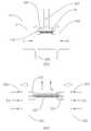
도 2의 (가)는 기화 칩(13)이 고정되는 공급 용기 및 기화 유도 유닛의 실시 예를 도시한 것이고 도 2의 (나)는 기화 유도 유닛에 고정되는 기화 칩(13)의 실시 예를 도시한 것이다.2A illustrates an embodiment of a supply container and a vaporization induction unit to which the
도 2에서 도 1a 또는 도 1b와 동일한 도면 부호를 가지는 구성 요소는 동일 또는 유사한 기능을 가지므로 반복하여 설명하지 않는다.In FIG. 2, components having the same reference numerals as those of FIG. 1A or 1B have the same or similar functions and thus will not be repeatedly described.
도 2의 (가)를 참조하면, 수용 공간((V)을 형성하는 기화 부분(122)의 길이 방향의 벽면을 따라 반원형의 단면을 가지는 한 쌍의 결합 홈(21a, 21b)이 형성될 수 있다. 그리고 결합 홈(21a, 21b)을 따라 다수 개의 공급 틈(211)이 배치될 수 있다. 공급 용기에 저장된 용액은 공급 틈(211)을 따라 저장 매체 장치(131)로 전달될 수 있다.Referring to FIG. 2A, a pair of
도 2의 (나)를 참조하면 저장 매체 장치(131)는 일부가 결합 홈(21a, 21b)에 결합될 수 있는 형상을 가질 수 있다. 구체적으로 저장 매체 장치(131)는 단면이 원형인 튜브 형상이 될 수 있고 일부가 결합 홈(21a, 21b)에 고정될 수 있다. 다른 한편으로 저장 매체 장치(131)에 공급 틈(221)이 형성될 수 있다. 공급 틈(221)은 결합 홈(21a, 21b)에 형성된 공급 틈(211)을 통하여 공급된 용액을 저장 매체 장치(131)로 전달하는 기능을 가진다. 그러므로 공급 틈(221)은 저장 매체 장치(131)가 결합 홈(21a, 21b)에 접촉하는 표면에 형성될 수 있다.Referring to FIG. 2B, the
공급 틈(211, 221)을 통하여 저장 매체 장치(131)의 내부로 전달된 용액은 공급 커넥터(132)를 통하여 기화 장치로 전달될 수 있다. 도 2의 (나)에 도시된 것처럼, 공급 커넥터(132)는 2개의 판이 겹쳐지고 내부에 용액 공급 수단(134)이 삽입된 구조를 가질 수 있다.The solution transferred into the
도 2에 제시된 기화 칩(13)의 고정 구조는 예시적인 것으로 본 발명은 제시된 실시 예에 제한되지 않는다. 용액은 공급 용기로부터 공급 틈(211, 221)을 통하여 저장 매체 장치(131)로 전달될 수 있고 다시 공급 커넥터(132)를 통하여 기화 장치로 전달될 수 있다. 공급 틈(211, 221)은 다양한 형상이 될 수 있고 저장 매체 장치(131)도 마찬가지로 다양한 형상을 가질 수 있다. 그리고 결합 홈(21a, 21b)은 저장 매체 장치(131)의 일부를 수용하여 고정할 수 있는 적절한 구조를 가질 수 있다.The fixing structure of the
아래에서 본 발명에 다른 카트리지에서 기화가 발생되는 실시 예에 대하여 설명한다.Hereinafter, an embodiment in which vaporization occurs in another cartridge according to the present invention will be described.
도 3의 (가) 및 (나)를 참조하면, 공급 용기(11)에 채워진 용액(S)은 F1로 표시된 경로로 공급 틈(221)을 통하여 기화 칩의 저장 매체 장치(131)로 유입될 수 있다. 저장 매체 장치(131)에 유입된 용액은 공급 커넥터(132)를 통하여 다시 공급 전달 수단(134)을 채우게 된다. 구체적으로 모세관 현상을 통하여 공급 용기(11)로부터 공급 전달 수단(134)으로 용액이 전달될 수 있다.Referring to (a) and (b) of FIG. 3, the solution S filled in the
열 발생 수단(135)에서 용액의 기화가 발생하지 않는 경우 충분한 양의 용액이 용액 공급 수단(134)으로 전달되면 더 이상의 용액이 전달되지 않는다. 이후 기화가 발생하면 기화 성분은 G로 표시된 것처럼 유도 튜브(121)를 통하여 배출되고 용액 전달 수단(134)에 존재하는 용액이 감소함에 따라 저장 매체 장치(131)에 저장된 용액이 다시 용액 전달 수단(134)으로 공급된다. 그리고 저장 매체 장치(131)의 용액 감소는 공급 틈(221)을 통한 용액의 유입에 의하여 보충될 수 있다. 이와 같은 과정을 통하여 공급 용기(11)의 용액의 완전히 소진되면 공급 용기(11) 및 기화 유도 유닛은 기화 칩으로부터 분리되고 새로운 공급 용기(11) 및 기화 유도 유닛이 기화 칩에 결합될 수 있다. 또는 공급 용기(11)에 용액을 충전시킬 수 있다. 이와 같이 본 발명에 따르면 일정량의 용액만 용액 전달 수단(134)으로 공급되고 기화에 의하여 용액이 완전히 소진이 되면 공급 용기가 교체되거나 또는 용액이 공급 용기에 보충될 수 있다. 그러므로 본 발명에 따라 용액의 누설이 방지되면서 이와 동시에 기기의 사용에 따른 비용이 감소될 수 있다.If vaporization of the solution does not occur in the heat generating means 135, when a sufficient amount of the solution is delivered to the solution supply means 134, no further solution is delivered. Then, when vaporization occurs, the vaporized component is discharged through the
본 발명에 따른 카트리지는 전자담배 또는 금연 보조 기기에 적용이 되어 공급 용액이 모두 소진된 경우 공급 용기의 충전 또는 교환이 가능하도록 하는 것에 의하여 전자담배의 사용 편리성이 향상되도록 하면서 사용에 따른 비용이 감소되도록 한다는 이점을 가진다. 또한 본 발명에 따른 카트리지는 공급 용기 및 히터가 분리 가능하도록 하면서 용액 전달 매개 수단에 의하여 기화 수단에 용액이 일정량으로 공급이 될 수 있도록 하는 것에 의하여 제품의 품질이 향상될 수 있도록 한다는 장점을 가진다. 추가로 본 발명에 따른 카트리지는 기화 수단의 노출에 따라 발생할 수 있는 누설이 방지될 수 있도록 하는 것에 의하여 전자담배의 청결 및 작동 오류가 방지될 수 있도록 한다는 장점을 가진다.The cartridge according to the present invention is applied to an electronic cigarette or a smoking cessation aid, so that when the supply solution is exhausted, it is possible to charge or exchange the supply container, thereby improving the convenience of using the electronic cigarette, while increasing the cost of use. Has the advantage of being reduced. In addition, the cartridge according to the present invention has the advantage that the quality of the product can be improved by allowing the supply vessel and the heater to be detachable while the solution can be supplied to the vaporization means by a predetermined amount by the solution delivery medium means. In addition, the cartridge according to the present invention has the advantage that the cleanliness and the operation error of the e-cigarette can be prevented by allowing leakage which may occur due to the exposure of the vaporization means.
위에서 본 발명의 제시된 실시 예를 참조하여 상세하게 설명이 되었지만 이 분야에서 통상의 지식을 가진 자는 제시된 실시 예를 참조하여 본 발명의 기술적 사상을 벗어나지 않는 범위에서 다양한 변형 및 수정 발명을 만들 수 있을 것이다. 본 발명은 이와 같은 변형 및 수정 발명에 의하여 제한되지 않으며 다만 아래에 첨부된 청구범위에 의하여 제한된다.Although described in detail above with reference to the embodiments of the present invention, those skilled in the art will be able to make various modifications and modifications to the invention without departing from the spirit of the present invention with reference to the embodiments presented. . The invention is not limited by these variations and modifications, but is limited only by the claims appended hereto.
10: 카트리지 11: 공급 용기
12: 기화 유도 유닛 13: 기화 칩
14: 흡입 마개
121: 유도 튜브 122: 기화 부분
123: 하부 플레이트 124: 결합 홈
125: 밀폐 플레이트 125a: 고정 홀
131: 저장 매체 장치 132: 공급 커넥터
133: 전극 리드 134: 용액 전달 수단
135: 열 발생 수단 141: 배출 통로
151: 삽입 홈
211, 221: 공급 틈
41: 배터리 어셈블리 42: 기화 어셈블리
43: 발광체 44: 흡입 어셈블리
411: 배터리 421: 하우징
422: 공기 유도로 423: 히터
424: 기화기 425: 공기 유도로
426: 공급 용기 441: 흡입 통로
442: 배출구
V: 수용 공간 H: 선택 투과 판 S: 용액10: cartridge 11: supply container
12: vaporization induction unit 13: vaporization chip
14: suction plug
121: induction tube 122: vaporization portion
123: lower plate 124: coupling groove
125: sealing
131: storage medium device 132: supply connector
133: electrode lead 134: solution delivery means
135: heat generating means 141: discharge passage
151: insertion groove
211, 221: supply gap
41: battery assembly 42: vaporization assembly
43: light emitter 44: suction assembly
411: Battery 421: Housing
422: air induction furnace 423: heater
424: carburetor 425: air induction furnace
426: supply container 441: suction passage
442: outlet
V: receiving space H: permeable plate S: solution
Claims (6)
Translated fromKorean내부에 기화 용액이 수용될 수 있는 공간이 형성된 공급 용기(11);
수용 공간(V)이 형성되고 공급 용기(11)의 한쪽 끝에 결합되는 기화 유도 유닛(12); 및
공급 용기(11)로부터 용액이 전달되어 저장될 수 있는 저장 매개 장치(131) 및 저장 매개 장치(131)로부터 용액을 전달받아 기화를 시키는 기화 장치로 이루어진 기화 칩(13)을 포함하고,
상기 기화 칩(13)의 적어도 일부는 전도성 소재가 되어 기화 장치에 전력을 공급할 수 있고 기화 칩(13)은 기하 유닛(12)에 분리 가능하도록 결합이 되는 것을 특징으로 하는 카트리지.In a cartridge for the supply of vaporization solution,
A supply container 11 formed with a space therein for containing a vaporization solution;
A vaporization induction unit 12 in which an accommodation space V is formed and coupled to one end of the supply container 11; And
And a vaporization chip 13 including a storage medium device 131 through which the solution is delivered from the supply vessel 11 and a vaporization device that receives the solution from the storage medium device 131 and vaporizes the solution.
At least a portion of the vaporization chip (13) is a conductive material can supply power to the vaporization device and the vaporization chip (13) is characterized in that the coupling to the geometry unit (12) detachably.
내부에 용액이 수용될 수 있는 공간이 형성된 공급 용기(11);
공급 용기(11)의 한쪽에 결합되고 공급 용기(11)의 내부에 형성된 수용 공간(V) 및 수용 공간(V)으로부터 연장되는 유도 튜브(122)를 포함하고 그리고 수용 공간(V)을 이루는 벽면에 공급 틈을 가진 결합 홈(124)이 형성된 기화 유도 유닛(12); 및
결합 홈(124)에 결합될 수 있고 공급 틈으로부터 전달되는 용액이 저장될 수 있는 저장 매개 장치(131), 용액을 기화시키기 위한 열 발생 수단(135)을 가지는 기화 장치 및 저장 매개 장치(131)와 기하 장치를 연결하는 공급 커넥터(132)를 포함하는 기화 칩(13)을 포함하고,
상기 공급 용기(11)로부터 저장 매개 장치(131)로 전달된 용액은 모세관 현상을 통하여 기화 장치로 전달되고 그리고 공급 용기(11)와 기화 유도 유닛(12)은 기화 칩(13)으로부터 분리 가능한 것을 특징으로 하는 카트리지.
In a cartridge for the supply of vaporization solution,
A supply container 11 having a space in which a solution can be accommodated;
A wall surface coupled to one side of the supply vessel 11 and including a receiving space V formed in the interior of the supply vessel 11 and an induction tube 122 extending from the receiving space V and forming the receiving space V; A vaporization induction unit 12 having a coupling groove 124 having a supply gap therein; And
A storage medium device 131 which can be coupled to the coupling groove 124 and in which a solution delivered from the supply gap can be stored, a vaporization device and a storage medium device 131 having heat generating means 135 for vaporizing the solution And a vaporization chip 13 including a supply connector 132 for connecting a and a geometry device,
The solution transferred from the supply vessel 11 to the storage medium apparatus 131 is transferred to the vaporization apparatus through a capillary phenomenon and the supply vessel 11 and the vaporization induction unit 12 are separated from the vaporization chip 13. The cartridge characterized.
Priority Applications (1)
| Application Number | Priority Date | Filing Date | Title |
|---|---|---|---|
| KR1020120029602AKR20130107658A (en) | 2012-03-22 | 2012-03-22 | Cartridge for supplying vaporization solution |
Applications Claiming Priority (1)
| Application Number | Priority Date | Filing Date | Title |
|---|---|---|---|
| KR1020120029602AKR20130107658A (en) | 2012-03-22 | 2012-03-22 | Cartridge for supplying vaporization solution |
Publications (1)
| Publication Number | Publication Date |
|---|---|
| KR20130107658Atrue KR20130107658A (en) | 2013-10-02 |
Family
ID=49630916
Family Applications (1)
| Application Number | Title | Priority Date | Filing Date |
|---|---|---|---|
| KR1020120029602ACeasedKR20130107658A (en) | 2012-03-22 | 2012-03-22 | Cartridge for supplying vaporization solution |
Country Status (1)
| Country | Link |
|---|---|
| KR (1) | KR20130107658A (en) |
Cited By (11)
| Publication number | Priority date | Publication date | Assignee | Title |
|---|---|---|---|---|
| EP3086671B1 (en) | 2013-12-23 | 2018-09-26 | Juul Labs UK Holdco Limited | Vaporization device systems |
| US20180360130A1 (en)* | 2013-12-23 | 2018-12-20 | Juul Labs, Inc. | Vaporization device systems and methods |
| US10653186B2 (en) | 2013-11-12 | 2020-05-19 | VMR Products, LLC | Vaporizer, charger and methods of use |
| US10667560B2 (en) | 2013-12-23 | 2020-06-02 | Juul Labs, Inc. | Vaporizer apparatus |
| US10709173B2 (en) | 2014-02-06 | 2020-07-14 | Juul Labs, Inc. | Vaporizer apparatus |
| US10865001B2 (en) | 2016-02-11 | 2020-12-15 | Juul Labs, Inc. | Fillable vaporizer cartridge and method of filling |
| US10912333B2 (en) | 2016-02-25 | 2021-02-09 | Juul Labs, Inc. | Vaporization device control systems and methods |
| US11019685B2 (en) | 2014-02-06 | 2021-05-25 | Juul Labs, Inc. | Vaporization device systems and methods |
| US11751605B2 (en) | 2016-02-11 | 2023-09-12 | Juul Labs, Inc. | Securely attaching cartridges for vaporizer devices |
| US11911557B2 (en) | 2018-10-15 | 2024-02-27 | Juul Labs, Inc. | Heating element |
| US12279646B2 (en) | 2014-02-06 | 2025-04-22 | Juul Labs, Inc. | Cartridge of vaporization device systems having unequal transverse cartridge dimensions |
- 2012
- 2012-03-22KRKR1020120029602Apatent/KR20130107658A/ennot_activeCeased
Cited By (30)
| Publication number | Priority date | Publication date | Assignee | Title |
|---|---|---|---|---|
| US10736360B2 (en) | 2013-11-12 | 2020-08-11 | Vmr Products Llc | Vaporizer, charger and methods of use |
| US12213535B2 (en) | 2013-11-12 | 2025-02-04 | Vmr Products Llc | Vaporizer |
| US11606981B2 (en) | 2013-11-12 | 2023-03-21 | Vmr Products Llc | Vaporizer |
| US10653186B2 (en) | 2013-11-12 | 2020-05-19 | VMR Products, LLC | Vaporizer, charger and methods of use |
| US10667561B2 (en) | 2013-11-12 | 2020-06-02 | Vmr Products Llc | Vaporizer |
| US11134722B2 (en) | 2013-11-12 | 2021-10-05 | Vmr Products Llc | Vaporizer |
| US11051557B2 (en) | 2013-11-12 | 2021-07-06 | VMR Products, LLC | Vaporizer |
| US10980273B2 (en) | 2013-11-12 | 2021-04-20 | VMR Products, LLC | Vaporizer, charger and methods of use |
| US10993471B2 (en) | 2013-12-23 | 2021-05-04 | Juul Labs, Inc. | Vaporization device systems and methods |
| EP3504990B1 (en) | 2013-12-23 | 2021-11-24 | Juul Labs International Inc. | Vaporization device systems and methods |
| US10912331B2 (en) | 2013-12-23 | 2021-02-09 | Juul Labs, Inc. | Vaporization device systems and methods |
| US20180360130A1 (en)* | 2013-12-23 | 2018-12-20 | Juul Labs, Inc. | Vaporization device systems and methods |
| US11992044B2 (en) | 2013-12-23 | 2024-05-28 | Juul Labs, Inc. | Vaporization device systems and methods |
| US10986867B2 (en)* | 2013-12-23 | 2021-04-27 | Juul Labs, Inc. | Vaporization device systems and methods |
| EP3086671B1 (en) | 2013-12-23 | 2018-09-26 | Juul Labs UK Holdco Limited | Vaporization device systems |
| US11752283B2 (en) | 2013-12-23 | 2023-09-12 | Juul Labs, Inc. | Vaporization device systems and methods |
| US10701975B2 (en) | 2013-12-23 | 2020-07-07 | Juul Labs, Inc. | Vaporization device systems and methods |
| EP3430921B1 (en) | 2013-12-23 | 2021-08-04 | Juul Labs International Inc. | Vaporization device systems |
| US10667560B2 (en) | 2013-12-23 | 2020-06-02 | Juul Labs, Inc. | Vaporizer apparatus |
| CN110269282A (en)* | 2013-12-23 | 2019-09-24 | 尤尔实验室有限公司 | Vaporising device system and method |
| US11452177B2 (en) | 2014-02-06 | 2022-09-20 | Juul Labs, Inc. | Vaporization device systems and methods |
| US11019685B2 (en) | 2014-02-06 | 2021-05-25 | Juul Labs, Inc. | Vaporization device systems and methods |
| US10709173B2 (en) | 2014-02-06 | 2020-07-14 | Juul Labs, Inc. | Vaporizer apparatus |
| US12279646B2 (en) | 2014-02-06 | 2025-04-22 | Juul Labs, Inc. | Cartridge of vaporization device systems having unequal transverse cartridge dimensions |
| US10865001B2 (en) | 2016-02-11 | 2020-12-15 | Juul Labs, Inc. | Fillable vaporizer cartridge and method of filling |
| US11751605B2 (en) | 2016-02-11 | 2023-09-12 | Juul Labs, Inc. | Securely attaching cartridges for vaporizer devices |
| US12063973B2 (en) | 2016-02-25 | 2024-08-20 | Juul Labs, Inc. | Vaporization device control systems and methods |
| US10912333B2 (en) | 2016-02-25 | 2021-02-09 | Juul Labs, Inc. | Vaporization device control systems and methods |
| US11911557B2 (en) | 2018-10-15 | 2024-02-27 | Juul Labs, Inc. | Heating element |
| US12420035B2 (en) | 2018-10-15 | 2025-09-23 | Juul Labs, Inc. | Atomizer assembly for a vaporizer device |
Similar Documents
| Publication | Publication Date | Title |
|---|---|---|
| KR20130107658A (en) | Cartridge for supplying vaporization solution | |
| CN109496130B (en) | Cartridges, battery packs and electronic cigarettes | |
| US11937637B2 (en) | Aerosol source for a vapor provision system | |
| JP6831048B2 (en) | Vapor supply device with liquid capture means | |
| KR102353237B1 (en) | Aerosol provision systems | |
| KR20130106741A (en) | Structure of cartridge capable of constant supply for electric cigarette | |
| CN113749313B (en) | Liquid storage tank for vapor supply system | |
| KR20130084789A (en) | Electronic cigarette | |
| JP7268824B2 (en) | Atomizer for steam supply system | |
| KR20130027909A (en) | Cartridge for electronic cigarette with enhanced inhaling flavor | |
| KR20160005323A (en) | Cartridge for electric cigarette capable of exchanging heat assembly | |
| US20220183360A1 (en) | Electronic Cigarette with Wick | |
| CN118749710A (en) | Housing for the atomizer cartridge portion of a vapor supply system | |
| KR20140045278A (en) | Cartridge for electric cigarette capable of exchanging heat assembly | |
| KR20120132070A (en) | Cartridge for Electronic Cigarette | |
| JP2019129759A (en) | Cartridge for sucker, sucker having the cartridge, and aerosol generation method | |
| KR101436392B1 (en) | Apparatus for Inhaling Gas Evaporated with Electrical Power | |
| KR101246816B1 (en) | Supplying Block for Supplying Nicotine Solution in Electric Cigarette | |
| KR101364016B1 (en) | Cartridge for electric cigarette capable of exchanging heat assembly | |
| KR20160082567A (en) | Container of Nicotine Solution for Electric Cigarette and Electric Cigarette with the Same | |
| KR101364031B1 (en) | Vaporizing Chip for Electronic Cigarette | |
| US20230301355A1 (en) | Liquid Sump for Heater | |
| KR101410498B1 (en) | Cartridge for Electronic Cigarette with Outer Inflow Holes | |
| KR20160080545A (en) | Supplying Block for Supplying Nicotine Solution in Electric Cigarette |
Legal Events
| Date | Code | Title | Description |
|---|---|---|---|
| A201 | Request for examination | ||
| PA0109 | Patent application | Patent event code:PA01091R01D Comment text:Patent Application Patent event date:20120322 | |
| PA0201 | Request for examination | ||
| E902 | Notification of reason for refusal | ||
| PE0902 | Notice of grounds for rejection | Comment text:Notification of reason for refusal Patent event date:20130705 Patent event code:PE09021S01D | |
| PG1501 | Laying open of application | ||
| E601 | Decision to refuse application | ||
| PE0601 | Decision on rejection of patent | Patent event date:20131128 Comment text:Decision to Refuse Application Patent event code:PE06012S01D Patent event date:20130705 Comment text:Notification of reason for refusal Patent event code:PE06011S01I |