KR20130105924A - Exposure apparatus, moving body driving system, pattern forming apparatus, exposure method and device manufacturing method - Google Patents
Exposure apparatus, moving body driving system, pattern forming apparatus, exposure method and device manufacturing methodDownload PDFInfo
- Publication number
- KR20130105924A KR20130105924AKR1020137022077AKR20137022077AKR20130105924AKR 20130105924 AKR20130105924 AKR 20130105924AKR 1020137022077 AKR1020137022077 AKR 1020137022077AKR 20137022077 AKR20137022077 AKR 20137022077AKR 20130105924 AKR20130105924 AKR 20130105924A
- Authority
- KR
- South Korea
- Prior art keywords
- respect
- movable body
- exposure
- moving body
- moving
- Prior art date
- Legal status (The legal status is an assumption and is not a legal conclusion. Google has not performed a legal analysis and makes no representation as to the accuracy of the status listed.)
- Granted
Links
Images


Classifications
- G—PHYSICS
- G03—PHOTOGRAPHY; CINEMATOGRAPHY; ANALOGOUS TECHNIQUES USING WAVES OTHER THAN OPTICAL WAVES; ELECTROGRAPHY; HOLOGRAPHY
- G03F—PHOTOMECHANICAL PRODUCTION OF TEXTURED OR PATTERNED SURFACES, e.g. FOR PRINTING, FOR PROCESSING OF SEMICONDUCTOR DEVICES; MATERIALS THEREFOR; ORIGINALS THEREFOR; APPARATUS SPECIALLY ADAPTED THEREFOR
- G03F7/00—Photomechanical, e.g. photolithographic, production of textured or patterned surfaces, e.g. printing surfaces; Materials therefor, e.g. comprising photoresists; Apparatus specially adapted therefor
- G03F7/70—Microphotolithographic exposure; Apparatus therefor
- G03F7/70216—Mask projection systems
- G03F7/70341—Details of immersion lithography aspects, e.g. exposure media or control of immersion liquid supply
- G—PHYSICS
- G03—PHOTOGRAPHY; CINEMATOGRAPHY; ANALOGOUS TECHNIQUES USING WAVES OTHER THAN OPTICAL WAVES; ELECTROGRAPHY; HOLOGRAPHY
- G03F—PHOTOMECHANICAL PRODUCTION OF TEXTURED OR PATTERNED SURFACES, e.g. FOR PRINTING, FOR PROCESSING OF SEMICONDUCTOR DEVICES; MATERIALS THEREFOR; ORIGINALS THEREFOR; APPARATUS SPECIALLY ADAPTED THEREFOR
- G03F7/00—Photomechanical, e.g. photolithographic, production of textured or patterned surfaces, e.g. printing surfaces; Materials therefor, e.g. comprising photoresists; Apparatus specially adapted therefor
- G03F7/70—Microphotolithographic exposure; Apparatus therefor
- G03F7/70425—Imaging strategies, e.g. for increasing throughput or resolution, printing product fields larger than the image field or compensating lithography- or non-lithography errors, e.g. proximity correction, mix-and-match, stitching or double patterning
- G—PHYSICS
- G03—PHOTOGRAPHY; CINEMATOGRAPHY; ANALOGOUS TECHNIQUES USING WAVES OTHER THAN OPTICAL WAVES; ELECTROGRAPHY; HOLOGRAPHY
- G03F—PHOTOMECHANICAL PRODUCTION OF TEXTURED OR PATTERNED SURFACES, e.g. FOR PRINTING, FOR PROCESSING OF SEMICONDUCTOR DEVICES; MATERIALS THEREFOR; ORIGINALS THEREFOR; APPARATUS SPECIALLY ADAPTED THEREFOR
- G03F7/00—Photomechanical, e.g. photolithographic, production of textured or patterned surfaces, e.g. printing surfaces; Materials therefor, e.g. comprising photoresists; Apparatus specially adapted therefor
- G03F7/70—Microphotolithographic exposure; Apparatus therefor
- G03F7/70483—Information management; Active and passive control; Testing; Wafer monitoring, e.g. pattern monitoring
- G03F7/7055—Exposure light control in all parts of the microlithographic apparatus, e.g. pulse length control or light interruption
- G—PHYSICS
- G03—PHOTOGRAPHY; CINEMATOGRAPHY; ANALOGOUS TECHNIQUES USING WAVES OTHER THAN OPTICAL WAVES; ELECTROGRAPHY; HOLOGRAPHY
- G03F—PHOTOMECHANICAL PRODUCTION OF TEXTURED OR PATTERNED SURFACES, e.g. FOR PRINTING, FOR PROCESSING OF SEMICONDUCTOR DEVICES; MATERIALS THEREFOR; ORIGINALS THEREFOR; APPARATUS SPECIALLY ADAPTED THEREFOR
- G03F7/00—Photomechanical, e.g. photolithographic, production of textured or patterned surfaces, e.g. printing surfaces; Materials therefor, e.g. comprising photoresists; Apparatus specially adapted therefor
- G03F7/70—Microphotolithographic exposure; Apparatus therefor
- G03F7/70691—Handling of masks or workpieces
- G03F7/70775—Position control, e.g. interferometers or encoders for determining the stage position
- G—PHYSICS
- G03—PHOTOGRAPHY; CINEMATOGRAPHY; ANALOGOUS TECHNIQUES USING WAVES OTHER THAN OPTICAL WAVES; ELECTROGRAPHY; HOLOGRAPHY
- G03F—PHOTOMECHANICAL PRODUCTION OF TEXTURED OR PATTERNED SURFACES, e.g. FOR PRINTING, FOR PROCESSING OF SEMICONDUCTOR DEVICES; MATERIALS THEREFOR; ORIGINALS THEREFOR; APPARATUS SPECIALLY ADAPTED THEREFOR
- G03F7/00—Photomechanical, e.g. photolithographic, production of textured or patterned surfaces, e.g. printing surfaces; Materials therefor, e.g. comprising photoresists; Apparatus specially adapted therefor
- G03F7/70—Microphotolithographic exposure; Apparatus therefor
- G03F7/708—Construction of apparatus, e.g. environment aspects, hygiene aspects or materials
- G03F7/70908—Hygiene, e.g. preventing apparatus pollution, mitigating effect of pollution or removing pollutants from apparatus
- G—PHYSICS
- G03—PHOTOGRAPHY; CINEMATOGRAPHY; ANALOGOUS TECHNIQUES USING WAVES OTHER THAN OPTICAL WAVES; ELECTROGRAPHY; HOLOGRAPHY
- G03F—PHOTOMECHANICAL PRODUCTION OF TEXTURED OR PATTERNED SURFACES, e.g. FOR PRINTING, FOR PROCESSING OF SEMICONDUCTOR DEVICES; MATERIALS THEREFOR; ORIGINALS THEREFOR; APPARATUS SPECIALLY ADAPTED THEREFOR
- G03F7/00—Photomechanical, e.g. photolithographic, production of textured or patterned surfaces, e.g. printing surfaces; Materials therefor, e.g. comprising photoresists; Apparatus specially adapted therefor
- G03F7/70—Microphotolithographic exposure; Apparatus therefor
- G03F7/708—Construction of apparatus, e.g. environment aspects, hygiene aspects or materials
- G03F7/70975—Assembly, maintenance, transport or storage of apparatus
- G—PHYSICS
- G03—PHOTOGRAPHY; CINEMATOGRAPHY; ANALOGOUS TECHNIQUES USING WAVES OTHER THAN OPTICAL WAVES; ELECTROGRAPHY; HOLOGRAPHY
- G03F—PHOTOMECHANICAL PRODUCTION OF TEXTURED OR PATTERNED SURFACES, e.g. FOR PRINTING, FOR PROCESSING OF SEMICONDUCTOR DEVICES; MATERIALS THEREFOR; ORIGINALS THEREFOR; APPARATUS SPECIALLY ADAPTED THEREFOR
- G03F9/00—Registration or positioning of originals, masks, frames, photographic sheets or textured or patterned surfaces, e.g. automatically
- G03F9/70—Registration or positioning of originals, masks, frames, photographic sheets or textured or patterned surfaces, e.g. automatically for microlithography
- G03F9/7073—Alignment marks and their environment
- G—PHYSICS
- G03—PHOTOGRAPHY; CINEMATOGRAPHY; ANALOGOUS TECHNIQUES USING WAVES OTHER THAN OPTICAL WAVES; ELECTROGRAPHY; HOLOGRAPHY
- G03F—PHOTOMECHANICAL PRODUCTION OF TEXTURED OR PATTERNED SURFACES, e.g. FOR PRINTING, FOR PROCESSING OF SEMICONDUCTOR DEVICES; MATERIALS THEREFOR; ORIGINALS THEREFOR; APPARATUS SPECIALLY ADAPTED THEREFOR
- G03F9/00—Registration or positioning of originals, masks, frames, photographic sheets or textured or patterned surfaces, e.g. automatically
- G03F9/70—Registration or positioning of originals, masks, frames, photographic sheets or textured or patterned surfaces, e.g. automatically for microlithography
- G03F9/7088—Alignment mark detection, e.g. TTR, TTL, off-axis detection, array detector, video detection
- G—PHYSICS
- G03—PHOTOGRAPHY; CINEMATOGRAPHY; ANALOGOUS TECHNIQUES USING WAVES OTHER THAN OPTICAL WAVES; ELECTROGRAPHY; HOLOGRAPHY
- G03F—PHOTOMECHANICAL PRODUCTION OF TEXTURED OR PATTERNED SURFACES, e.g. FOR PRINTING, FOR PROCESSING OF SEMICONDUCTOR DEVICES; MATERIALS THEREFOR; ORIGINALS THEREFOR; APPARATUS SPECIALLY ADAPTED THEREFOR
- G03F9/00—Registration or positioning of originals, masks, frames, photographic sheets or textured or patterned surfaces, e.g. automatically
- G03F9/70—Registration or positioning of originals, masks, frames, photographic sheets or textured or patterned surfaces, e.g. automatically for microlithography
- G03F9/7096—Arrangement, mounting, housing, environment, cleaning or maintenance of apparatus
- Y—GENERAL TAGGING OF NEW TECHNOLOGICAL DEVELOPMENTS; GENERAL TAGGING OF CROSS-SECTIONAL TECHNOLOGIES SPANNING OVER SEVERAL SECTIONS OF THE IPC; TECHNICAL SUBJECTS COVERED BY FORMER USPC CROSS-REFERENCE ART COLLECTIONS [XRACs] AND DIGESTS
- Y10—TECHNICAL SUBJECTS COVERED BY FORMER USPC
- Y10T—TECHNICAL SUBJECTS COVERED BY FORMER US CLASSIFICATION
- Y10T29/00—Metal working
- Y10T29/49—Method of mechanical manufacture
- Y10T29/49002—Electrical device making
Landscapes
- General Physics & Mathematics (AREA)
- Physics & Mathematics (AREA)
- Engineering & Computer Science (AREA)
- Epidemiology (AREA)
- Health & Medical Sciences (AREA)
- Public Health (AREA)
- Multimedia (AREA)
- Environmental & Geological Engineering (AREA)
- Life Sciences & Earth Sciences (AREA)
- Atmospheric Sciences (AREA)
- Exposure And Positioning Against Photoresist Photosensitive Materials (AREA)
- Container, Conveyance, Adherence, Positioning, Of Wafer (AREA)
- Exposure Of Semiconductors, Excluding Electron Or Ion Beam Exposure (AREA)
- Length Measuring Devices By Optical Means (AREA)
- Optical Transform (AREA)
Abstract
Translated fromKoreanDescription
Translated fromKorean본 발명은, 노광 장치, 이동체 구동 시스템, 패턴 형성 장치 및 노광 방법, 그리고 디바이스 제조 방법에 관한 것으로, 더욱 상세하게는, 반도체 소자, 액정 표시 소자 등의 전자 디바이스를 제조할 때에 리소그래피 공정에서 사용되는 노광 장치, 그 노광 장치에 바람직하게 사용할 수 있고, 인코더 시스템을 사용하여 이동체의 위치를 계측하는 이동체 구동 시스템, 그 이동체 구동 시스템을 구비하는 패턴 형성 장치, 및 리소그래피 공정에서 사용되는 노광 방법, 그리고 상기 노광 장치 또는 노광 방법을 이용하는 디바이스 제조 방법에 관한 것이다.TECHNICAL FIELD The present invention relates to an exposure apparatus, a moving body driving system, a pattern forming apparatus and an exposure method, and a device manufacturing method, and more particularly, to be used in a lithography process when manufacturing electronic devices such as semiconductor elements and liquid crystal display elements. A movable body drive system which can be used suitably for an exposure apparatus, the exposure apparatus, and measures the position of a movable body using an encoder system, a pattern forming apparatus provided with the movable body driving system, and the exposure method used in a lithography process, and the said A device manufacturing method using an exposure apparatus or an exposure method.
종래, 반도체 소자 (집적 회로 등), 액정 표시 소자 등의 전자 디바이스 (마이크로 디바이스) 를 제조하는 리소그래피 공정에서는, 스텝·앤드·리피트 방식의 투영 노광 장치 (이른바 스테퍼), 스텝·앤드·스캔 방식의 투영 노광 장치 (이른바 스캐닝·스테퍼 (스캐너라고도 한다)) 등이 주로 사용되고 있다.Conventionally, in the lithography process for manufacturing electronic devices (micro devices) such as semiconductor elements (integrated circuits), liquid crystal display elements, etc., the projection exposure apparatus (so-called stepper) of the step-and-repeat method and the step-and-scan method Projection exposure apparatuses (so-called scanning steppers (also called scanners)) and the like are mainly used.
이런 종류의 노광 장치로 웨이퍼의 노광을 실시하면, 웨이퍼의 주변부에 노광되지 않는 부분 (즉, 제품 (칩) 으로서 사용할 수 없는 영역) 이 발생한다. 그런데, 이러한 노광되지 않는 부분 (영역) 의 존재는, 패턴이 형성된 웨이퍼의 표면을 평탄화하기 위해서 적용되는 화학 기계적 연마 (CMP) 공정에 있어서 문제가 된다. 그래서, 종래에도 웨이퍼의 주변부에서 유효 노광 영역으로부터 일부가 비어져 나오는 쇼트 영역 (이하 「주변 쇼트」라고 한다) 중 디바이스로서 사용할 수 없는 부분을 노광하는 주변 노광을 실시하는 것이 이루어지고 있다 (예를 들어 특허 문헌 1 참조).When the wafer is exposed with this kind of exposure apparatus, a portion (that is, a region that cannot be used as a product (chip)) is generated in the peripheral portion of the wafer. By the way, the presence of such an unexposed part (region) becomes a problem in the chemical mechanical polishing (CMP) process applied in order to planarize the surface of the patterned wafer. Therefore, conventionally, the peripheral exposure which exposes the part which cannot be used as a device in the shot area (henceforth "peripheral shot") which partly protrudes from the effective exposure area | region in the periphery of a wafer is performed (for example, See Patent Document 1).
그러나, 레티클의 패턴을 웨이퍼 상에 전사 형성하는 노광과는 별도로 주변 노광을 실시하는 경우, 그 주변 노광에 필요로 하는 시간만큼 스루풋이 저하되어 버린다.However, when the peripheral exposure is performed separately from the exposure for transferring the reticle pattern onto the wafer, throughput decreases by the time required for the peripheral exposure.
한편, 스루풋을 향상시키는 수법으로서, 웨이퍼를 유지하는 웨이퍼 스테이지를 복수, 예를 들어 2 개 형성하고, 그 2 개의 웨이퍼 스테이지에서 상이한 동작을 동시 병행적으로 처리하는 수법을 채용하는 트윈 웨이퍼 스테이지 타입의 노광 장치가 여러 가지 제안되어 있다. 최근에는, 액침 노광법을 채용한 트윈 웨이퍼 스테이지 타입의 노광 장치가 제안되어 있다 (예를 들어 특허 문헌 2 참조).On the other hand, as a technique for improving the throughput, a twin wafer stage type employing a method of forming a plurality of wafer stages holding a wafer, for example, two, and simultaneously processing different operations in the two wafer stages in parallel. Various exposure apparatuses are proposed. In recent years, the exposure apparatus of the twin wafer stage type which employ | adopted the liquid immersion exposure method is proposed (for example, refer patent document 2).
그런데, 디바이스 룰 (실용 최소 선폭) 은 점차 미세화되고, 이에 따라 노광 장치에는 보다 고정밀한 중첩 성능이 요구된다. 이 때문에, 웨이퍼 얼라이먼트의 주류인 인헨스드·글로벌·얼라이먼트 (EGA) 의 샘플 쇼트 수도 한층 더 증가가 예상되어, 트윈 웨이퍼 스테이지 타입의 노광 장치라도 스루풋의 저하가 우려된다.By the way, the device rule (the practical minimum line width) is gradually refined, and accordingly, the exposure apparatus requires a more precise superposition performance. For this reason, the number of sample shots of the enhanced global alignment (EGA), which is the mainstream of wafer alignment, is also expected to be further increased, and even a twin wafer stage type exposure apparatus may reduce the throughput.
또한, 스테퍼, 스캐너 등의 노광 장치에서는, 예를 들어 웨이퍼를 유지하는 스테이지의 위치 계측은 레이저 간섭계를 사용하여 실시되는 것이 일반적이었다. 그런데, 반도체 소자의 고집적화에 따른 패턴의 미세화에 의해, 요구되는 성능이 엄격해져, 현재, 레이저 간섭계의 빔로 상의 분위기의 온도 변화 및/또는 온도 구배의 영향으로 발생하는 공기 흔들림에서 기인되는 계측값의 단기적인 변동을 무시할 수 없게 되었다.Moreover, in exposure apparatuses, such as a stepper and a scanner, the position measurement of the stage holding a wafer, for example was generally performed using a laser interferometer. However, the finer the pattern resulting from the higher integration of semiconductor elements, the more demanding the performance becomes, and at present the measurement value resulting from air fluctuations caused by the influence of temperature changes and / or temperature gradients in the atmosphere on the beam path of the laser interferometer. Short-term fluctuations cannot be ignored.
그래서, 최근에는 간섭계에 비해 공기 흔들림의 영향을 잘 받지 않는 고분해능의 인코더가 주목되게 되었고, 그 인코더를 웨이퍼 스테이지 등의 위치 계측에 사용하는 노광 장치가 발명자들에 의해 제안되었다 (예를 들어 특허 문헌 3 등 참조).Therefore, in recent years, high-resolution encoders, which are less affected by air shaking compared to interferometers, have been attracting attention, and exposure apparatuses using the encoders for position measurement of wafer stages and the like have been proposed by the inventors (for example, patent documents). 3, etc.).
그러나, 상기 특허 문헌 3 의 실시형태 중에 기재된 노광 장치와 동일하게 웨이퍼 스테이지 상면에 스케일 (그레이팅) 을 형성하는 경우, 인코더 헤드의 수가 많기 때문에, 그 배치에 자유도가 거의 없고, 또한 레이아웃이 곤란했다.However, when the scale (grating) is formed on the upper surface of the wafer stage in the same way as the exposure apparatus described in the embodiment of Patent Document 3, since the number of encoder heads is large, there is little freedom in the arrangement and layout is difficult.
특허 문헌 1 : 일본 공개특허공보 2006-278820호Patent Document 1: Japanese Unexamined Patent Publication No. 2006-278820
특허 문헌 2 : 미국 특허 제7,161,659호 명세서Patent Document 2: US Patent No. 7,161,659
특허 문헌 3 : 국제 공개 제2007/097379호 팜플렛Patent Document 3: International Publication No. 2007/097379 Pamphlet
본 발명은, 제 1 관점에서 보면, 노광 빔으로 물체를 노광하는 노광 장치로서, 상기 물체를 유지하여 서로 직교하는 제 1 축 및 제 2 축을 포함하는 소정 평면을 따라 이동하는 이동체와 ; 상기 노광이 실시되는 노광 위치로부터 상기 제 1 축과 평행한 방향으로 떨어져 배치되고, 상기 물체에 대한 소정의 계측을 실시하는 계측 시스템과 ; 상기 계측 시스템으로부터 상기 제 1 축과 평행한 방향으로 떨어져 배치되고, 상기 물체 주변의 쇼트 영역의 적어도 일부를 노광하는 주변 노광 시스템을 구비하는 제 1 노광 장치이다.According to a first aspect, the present invention provides an exposure apparatus for exposing an object with an exposure beam, comprising: a moving body holding the object and moving along a predetermined plane including a first axis and a second axis orthogonal to each other; A measurement system which is disposed away from the exposure position at which the exposure is performed, in a direction parallel to the first axis, and performs a predetermined measurement on the object; It is a 1st exposure apparatus which is arrange | positioned apart in the direction parallel to a said 1st axis | shaft from the said measurement system, and is provided with the peripheral exposure system which exposes at least one part of the shot area | region around the said object.
이것에 의하면, 소정 평면 내의 제 1 축과 평행한 방향을 따라 물체를 유지하는 이동체가 이동하는 동안에, 물체 주변의 쇼트 영역의 적어도 일부가 주변 노광 시스템에 의해 노광된다. 이로써, 계측 시스템으로부터 노광 위치를 향한 물체 (이동체) 의 이동, 또는 그 반대 방향으로의 물체 (이동체) 의 이동 (예를 들어 노광 위치로부터 물체의 교환 위치로의 이동체의 이동) 과 병행하여 주변 노광을 실시할 수 있어, 주변 노광을 독립적으로 실시하는 경우와 달리 스루풋을 거의 저하시키는 경우가 없다.According to this, at least a part of the shot area around the object is exposed by the peripheral exposure system while the moving object holding the object along the direction parallel to the first axis in the predetermined plane is moved. This allows peripheral exposure in parallel with the movement of the object (moving body) from the measurement system toward the exposure position or the movement of the object (moving body) in the opposite direction (for example, the movement of the moving body from the exposure position to the exchange position of the object). Can be implemented, and the throughput is hardly reduced unlike in the case of performing the peripheral exposure independently.
본 발명은, 제 2 관점에서 보면, 노광 빔으로 물체를 노광하는 노광 장치로서, 상기 물체를 유지하여 서로 직교하는 제 1 축 및 제 2 축을 포함하는 소정 평면 내를 이동할 수 있는 이동체와 ; 상기 노광이 실시되는 노광 위치와, 상기 제 1 축과 평행한 방향에 관하여 상기 노광 위치로부터 떨어져 배치되는 상기 물체의 교환 위치 사이에 형성되고, 상기 물체 상에서 상기 노광이 실시되는 영역과 상이한 주변 영역의 적어도 일부를 노광하는 주변 노광 시스템을 구비하고, 상기 노광 위치 및 상기 교환 위치 중 일방으로부터 타방으로의 상기 이동체의 이동 동작과 병행하여, 상기 주변 영역의 노광 동작의 적어도 일부가 실시되는 제 2 노광 장치이다.According to a second aspect of the present invention, there is provided an exposure apparatus for exposing an object with an exposure beam, comprising: a movable body capable of holding the object and moving in a predetermined plane including a first axis and a second axis orthogonal to each other; Between an exposure position at which the exposure is performed and an exchange position of the object disposed away from the exposure position with respect to a direction parallel to the first axis, the peripheral region being different from the region at which the exposure is performed on the object; A second exposure apparatus including a peripheral exposure system that exposes at least a portion, and at least a part of the exposure operation of the peripheral region is performed in parallel with the movement operation of the movable body from one of the exposure positions and the replacement positions to the other. to be.
이것에 의하면, 노광 위치 및 상기 교환 위치 중 일방으로부터 타방으로의 상기 이동체의 이동 동작과 병행하여, 주변 노광 시스템에 의한 주변 영역의 노광 동작의 적어도 일부가 실시된다. 따라서, 주변 노광을 독립적으로 실시하는 경우와 달리 스루풋을 거의 저하시키는 경우가 없다.According to this, at least one part of the exposure operation of the peripheral area by a peripheral exposure system is performed in parallel with the movement operation | movement of the said moving body from one of the exposure position and the said exchange position to the other. Therefore, unlike the case where the peripheral exposure is performed independently, the throughput hardly decreases.
본 발명은, 제 3 관점에서 보면, 에너지 빔으로 물체를 노광하여 상기 물체 상에 패턴을 형성하는 노광 장치로서, 물체를 유지하여 서로 직교하는 제 1 축 및 제 2 축을 포함하는 소정의 평면 내에서 이동하는 제 1 이동체와 ; 물체를 유지하여 상기 평면 내에서 상기 제 1 이동체와는 독립적으로 이동하는 제 2 이동체와 ; 상기 제 2 축과 평행한 방향에 관하여 위치가 상이한 복수의 검출 영역을 갖고, 상기 제 1 이동체 및 제 2 이동체 상에 각각 탑재된 상기 물체 상의 마크를 검출하는 마크 검출계와 ; 상기 제 1 이동체 및 제 2 이동체 중 일방에 유지된 물체에 대한 노광이 실시되는 것과 병행하여, 상기 제 1 이동체 및 제 2 이동체 중 타방을 상기 제 1 축과 평행한 방향으로 이동시키면서, 그 타방의 이동체에 유지된 물체 상의 상이한 복수의 마크를 상기 마크 검출계에 의해 검출하여 그 위치 정보를 계측하는 제어 장치를 구비하는 제 3 노광 장치이다.According to a third aspect, the present invention provides an exposure apparatus for exposing an object with an energy beam to form a pattern on the object, wherein the exposure apparatus is configured to hold an object in a predetermined plane including a first axis and a second axis orthogonal to each other. A first moving body moving; A second movable body for holding an object and moving independently of the first movable body in the plane; A mark detection system having a plurality of detection regions different in position with respect to a direction parallel to the second axis, and detecting a mark on the object mounted on the first moving body and the second moving body, respectively; In parallel with exposure of an object held on one of the first movable body and the second movable body, the other of the first movable body and the second movable body is moved in a direction parallel to the first axis, It is the 3rd exposure apparatus provided with the control apparatus which detects several different marks on the object hold | maintained by the movable body by the said mark detection system, and measures the positional information.
이것에 의하면, 제어 장치에 의해, 제 1 이동체 및 제 2 이동체 중 일방에 유지된 물체에 대한 노광이 실시되는 것과 병행하여, 제 1 이동체 및 제 2 이동체 중 타방이 제 1 축과 평행한 방향으로 이동되면서, 그 타방의 이동체에 유지된 물체 상의 상이한 복수의 마크가 마크 검출계에 의해 검출되어 그 위치 정보가 계측된다. 따라서, 일방의 이동체에 유지된 물체의 노광이 실시되는 것과 병행하여, 타방의 이동체가 마크 검출계의 복수의 검출 영역 근방의 위치 (예를 들어 이동체에 유지된 물체의 교환이 실시되는 위치의 근방) 로부터 노광 위치를 향해 제 1 축 방향에 관하여 이동하는 동안에, 그 타방의 이동체에 유지된 물체 상의 복수의 마크, 예를 들어 모든 마크의 위치 정보를 검출할 수 있게 된다. 이 결과, 스루풋의 향상과 중첩 정밀도의 향상을 실현할 수 있게 된다.According to this, in parallel with exposure of the object hold | maintained to one of a 1st moving body and a 2nd moving body by a control apparatus, the other of a 1st moving body and a 2nd moving body is a direction parallel to a 1st axis | shaft. While moving, a plurality of different marks on the object held by the other moving object are detected by the mark detection system, and the positional information thereof is measured. Therefore, in parallel with exposure of the object held by one movable body, the other movable body is located near the plurality of detection regions of the mark detection system (for example, near the position where the exchange of the object held by the movable body is performed). It is possible to detect the positional information of a plurality of marks on the object held in the other movable body, for example, all the marks, while moving relative to the first axial direction toward the exposure position. As a result, the throughput and the overlapping accuracy can be improved.
본 발명은, 제 4 관점에서 보면, 에너지 빔으로 물체를 노광하여 상기 물체 상에 패턴을 형성하는 노광 장치로서, 물체를 유지하여 서로 직교하는 제 1 축 및 제 2 축을 포함하는 소정의 평면 내에서 이동하는 제 1 이동체와 ; 물체를 유지하여 상기 평면 내에서 상기 제 1 이동체와는 독립적으로 이동하는 제 2 이동체와 ; 상기 제 1 이동체, 제 2 이동체를 상기 평면 내에서 구동하는 평면 모터와 ; 상기 평면 모터를 제어함과 함께, 상기 제 1 이동체에 유지된 물체의 노광이 종료되었을 때에, 상기 제 1 이동체를 상기 노광이 실시되는 노광 위치의 상기 제 2 축과 평행한 방향의 일측에 위치하는 제 1 귀환 경로를 따라 상기 제 1 이동체 상의 물체의 교환이 실시되는 제 1 교환 위치로 이동시키고, 또한 상기 제 2 이동체에 유지된 물체의 노광이 종료되었을 때에, 상기 제 2 이동체를 상기 노광 위치의 상기 제 2 축과 평행한 방향의 타측에 위치하는 제 2 귀환 경로를 따라 상기 제 2 이동체 상의 물체의 교환이 실시되는 제 2 교환 위치로 이동시키는 제어 장치를 구비하는 제 4 노광 장치이다.The present invention is, in view of the fourth aspect, an exposure apparatus for exposing an object with an energy beam to form a pattern on the object, the exposure device being held in a predetermined plane including a first axis and a second axis that are orthogonal to each other. A first moving body moving; A second movable body for holding an object and moving independently of the first movable body in the plane; A plane motor for driving the first moving body and the second moving body in the plane; While controlling the planar motor, when the exposure of the object held by the first movable body is finished, the first movable body is located on one side in a direction parallel to the second axis of the exposure position at which the exposure is performed. When the exposure of the object held by the second movable body is finished, the second movable body is moved to the exposure position when the object on the first movable body is moved along the first return path. It is a 4th exposure apparatus provided with the control apparatus which moves to the 2nd exchange position where the exchange of the object on a said 2nd moving body is performed along the 2nd return path located on the other side of the direction parallel to a said 2nd axis.
이 경우에서, 제 1 교환 위치와 제 2 교환 위치는 동일해도 되고 상이해도 된다.In this case, the first exchange position and the second exchange position may be the same or different.
이것에 의하면, 제어 장치에 의해, 제 1 이동체, 제 2 이동체를 평면 내에서 구동하는 평면 모터가 제어됨과 함께, 제 1 이동체에 유지된 물체의 노광이 종료되었을 때에, 제 1 이동체가 노광 위치의 제 2 축과 평행한 방향의 일측에 위치하는 제 1 귀환 경로를 따라 제 1 이동체 상의 물체의 교환이 실시되는 제 1 교환 위치로 이동되고, 또한 제 2 이동체에 유지된 물체의 노광이 종료되었을 때에, 제 2 이동체가 노광 위치의 제 2 축과 평행한 방향의 타측에 위치하는 제 2 귀환 경로를 따라 제 2 이동체 상의 물체의 교환이 실시되는 제 2 교환 위치로 이동된다. 따라서, 제 1 이동체에는 제 2 축과 평행한 방향의 일측으로부터, 제 2 이동체에는 제 2 축과 평행한 방향의 타측으로부터, 각각 배선·배관용 케이블을 장착함으로써, 그들 케이블의 얽힘을 방지할 수 있음과 함께, 그 길이를 최대한 짧게 할 수 있다.According to this, while the control apparatus controls the plane motor which drives a 1st mobile body and a 2nd mobile body in a plane, when the exposure of the object hold | maintained on the 1st mobile body is complete | finished, a 1st mobile body is made into the exposure position. When the exposure of the object held by the second moving body is finished, the first moving position is moved along the first return path located on one side in a direction parallel to the second axis, and the exposure of the object held by the second moving body is completed. The second movable body is moved to the second exchange position where the exchange of objects on the second movable body is performed along the second return path located on the other side in the direction parallel to the second axis of the exposure position. Therefore, the cable for wiring and piping is attached to the first moving body from one side in the direction parallel to the second axis, and the second moving body from the other side in the direction parallel to the second axis, whereby entanglement of these cables can be prevented. In addition, the length can be made as short as possible.
본 발명은, 제 5 관점에서 보면, 에너지 빔으로 물체를 노광하여 상기 물체 상에 패턴을 형성하는 노광 장치로서, 물체를 유지하여 서로 직교하는 제 1 축 및 제 2 축을 포함하는 소정의 평면 내에서 이동하는 제 1 이동체와 ; 물체를 유지하여 상기 평면 내에서 상기 제 1 이동체와는 독립적으로 이동하는 제 2 이동체와 ; 상기 제 1 이동체 및 제 2 이동체를 상기 평면 내에서 구동하는 평면 모터와 ; 상기 에너지 빔을 사출하는 광학 부재와 ; 상기 광학 부재와 상기 제 1 이동체, 제 2 이동체 중 일방 사이에 액체를 공급하여 액침 영역을 형성하는 액침 장치와 ; 상기 일방의 이동체에 유지된 물체의 노광 종료 후, 상기 일방의 이동체로부터 타방의 이동체로 상기 액침 영역을 건네주기 위해서, 상기 제 1 이동체와 상기 제 2 이동체를 상기 제 1 축과 평행한 방향에 관하여 소정 거리 이하로 근접시키는 근접 상태와, 양 이동체를 이간시키는 이간 상태의 전환을 실시시킴과 함께, 상기 타방의 이동체로부터 이간된 상기 일방의 이동체를, 상기 제 2 축과 평행한 방향에 관하여 노광 위치의 일측에 위치하는 귀환 경로를 따라 상기 제 1 이동체, 제 2 이동체 상의 물체의 교환이 실시되는 교환 위치로 이동시키도록 상기 평면 모터를 제어하는 제어 장치를 구비하는 제 5 노광 장치이다.According to a fifth aspect, the present invention provides an exposure apparatus for exposing an object with an energy beam to form a pattern on the object, wherein the exposure apparatus is configured to hold an object in a predetermined plane including a first axis and a second axis that are orthogonal to each other. A first moving body moving; A second movable body for holding an object and moving independently of the first movable body in the plane; A plane motor for driving the first moving body and the second moving body in the plane; An optical member for emitting the energy beam; A liquid immersion apparatus for supplying a liquid between the optical member, one of the first movable body, and the second movable body to form a liquid immersion region; After the exposure of the object held by the one movable body is finished, the first movable body and the second movable body are directed in a direction parallel to the first axis in order to pass the immersion region from the one movable body to the other movable body. The switching of the proximity state which approaches below the predetermined distance, and the separation state which separates both moving bodies, and exposing the said movable body separated from the said other movable body with respect to the direction parallel to a said 2nd axis And a fifth exposure apparatus including a control device for controlling the planar motor to move to the exchange position at which the first object and the object on the second object are exchanged along a return path located at one side of the face.
여기서, 소정 거리 이하로 근접시키는 근접 상태에는, 제 1 이동체와 제 2 이동체를 제 1 축과 평행한 방향에 관하여 접촉시키는 상태, 즉 제 1 이동체와 제 2 이동체의 이간 거리가 0 인 상태를 포함한다. 본 명세서에서는, 접촉 상태라고 명시가 있는 경우는 물론, 특별히 명시가 없는 경우라도, 상기 이간 거리가 0 인 상태, 즉 접촉 상태도 포함하는 개념으로서 근접 상태라는 용어를 사용하고 있다.Here, the proximity state of approaching the predetermined distance or less includes a state in which the first moving body and the second moving body are brought into contact with each other in a direction parallel to the first axis, that is, a state in which the distance between the first moving body and the second moving body is zero. do. In the present specification, the term "proximity state" is used as a concept including the state where the separation distance is 0, that is, the contact state, as well as the case where the contact state is specified.
이것에 의하면, 제어 장치에 의해, 일방의 이동체에 유지된 물체의 노광 종료 후, 일방의 이동체로부터 타방의 이동체로 액침 영역을 건네주기 위해서, 양 이동체를 제 1 축과 평행한 방향에 관하여 소정 거리 이하로 근접시키는 근접 상태와, 양 이동체를 이간시키는 이간 상태의 전환을 실시시킴과 함께, 타방의 이동체로부터 이간된 일방의 이동체를, 제 2 축과 평행한 방향에 관하여 노광 위치의 일측에 위치하는 귀환 경로를 따라 제 1 이동체, 제 2 이동체 상의 물체의 교환이 실시되는 교환 위치로 이동시키도록 평면 모터가 제어된다. 이 때문에, 일방의 이동체를 제 2 축과 평행한 방향에 관하여 노광 위치의 일측에 위치하는 귀환 경로를 따라 교환 위치로 이동시키고, 타방의 이동체를 제 2 축과 평행한 방향에 관하여 노광 위치의 타측에 위치하는 귀환 경로를 따라 교환 위치로 이동시키는 경우 등에 비해, 양 이동체의 제 2 축과 평행한 방향에 관한 이동 범위를 좁게 설정할 수 있다.According to this, in order to pass the liquid immersion area | region from one mobile body to the other mobile body after completion | finish of exposure of the object hold | maintained on one mobile body by a control apparatus, both mobile bodies are predetermined distance with respect to the direction parallel to a 1st axis | shaft. While switching between the proximity state which approaches below and the separation state which separates both moving bodies, the one movable body separated from the other moving body is located in the one side of an exposure position with respect to the direction parallel to a 2nd axis | shaft. The plane motor is controlled to move along the return path to the exchange position where the exchange of the object on the first mobile body and the second mobile body is performed. For this reason, one movable body is moved to the exchange position along the return path located on one side of the exposure position with respect to the direction parallel to the second axis, and the other movable body is moved to the other side of the exposure position with respect to the direction parallel to the second axis. As compared with the case where it moves to an exchange position along the return path located in the inside, etc., the movement range regarding the direction parallel to the 2nd axis of both moving bodies can be set narrow.
본 발명은, 제 6 관점에서 보면, 실질적으로 소정 평면을 따라 이동체를 구동하는 이동체 구동 시스템으로서, 상기 소정 평면과 평행한 면 내에서 서로 직교하는 제 1, 제 2 방향을 주기 방향으로 하는 2 차원 격자를 갖는 스케일에 검출광을 조사하고, 상기 스케일로부터의 광을 수광하는 헤드를 갖고, 상기 헤드의 계측값에 기초하여, 상기 제 1, 제 2 방향을 포함하는 상기 소정 평면 내의 적어도 2 자유도 방향에 관한 상기 이동체의 위치 정보를 계측하는 인코더 시스템과 ; 상기 인코더 시스템의 계측 정보에 기초하여, 상기 이동체를 상기 소정 평면을 따라 구동하는 구동 장치를 구비하는 이동체 구동 시스템이다.According to a sixth aspect of the present invention, there is provided a moving body driving system for driving a moving body substantially along a predetermined plane, the two-dimensionally having a first and second directions orthogonal to each other in a plane parallel to the predetermined plane as a periodic direction. At least two degrees of freedom in the predetermined plane including the first and second directions, having a head that irradiates detection light to a scale having a grating and receives light from the scale, based on a measured value of the head. An encoder system for measuring positional information of the moving object with respect to a direction; It is a moving object drive system provided with the drive apparatus which drives the said moving body along the said predetermined plane based on the measurement information of the said encoder system.
이것에 의하면, 2 차원 격자를 갖는 스케일에 검출광을 조사하고, 스케일로부터의 반사광을 수광하는 헤드를 갖고, 헤드의 계측값에 기초하여, 제 1, 제 2 방향을 포함하는 상기 소정 평면 내의 적어도 2 자유도 방향에 관한 이동체의 위치 정보를 계측하는 인코더 시스템의 계측 정보에 기초하여, 구동 장치에 의해 이동체가 소정 평면을 따라 구동된다. 따라서, 제 1, 제 2 방향에 관한 이동체의 위치 정보를 각각 계측하는 1 차원 헤드를 복수 포함하는 인코더 시스템을 사용하는 경우에 비해, 헤드의 배치 자유도가 현격히 향상되고, 레이아웃이 용이해진다. 예를 들어, 스케일을 1 개만 사용함으로써, 소정 평면과 평행한 면 내의 2 자유도 방향에 관한 이동체의 위치를 계측할 수 있게 된다.According to this, it has a head which irradiates a detection light to the scale which has a two-dimensional grating, and receives the reflected light from the scale, and based on the measured value of the head, at least in the said predetermined plane including a 1st, 2nd direction On the basis of the measurement information of the encoder system for measuring the positional information of the moving object in the two degrees of freedom direction, the moving device is driven along a predetermined plane by the drive device. Accordingly, compared with the case of using an encoder system including a plurality of one-dimensional heads respectively measuring positional information of the moving objects in the first and second directions, the degree of freedom in arranging the heads is significantly improved, and the layout becomes easy. For example, by using only one scale, it is possible to measure the position of the moving object in two degrees of freedom in a plane parallel to the predetermined plane.
본 발명은, 제 7 관점에서 보면, 물체가 탑재되고, 그 물체를 유지하여 실질적으로 이동면을 따라 이동할 수 있는 이동체와 ; 상기 물체 상에 패턴을 생성하는 패터닝 장치와 ; 상기 물체에 대한 패턴 형성을 위해서, 상기 이동체를 구동하는 본 발명의 이동체 구동 시스템을 구비하는 패턴 형성 장치이다.According to a seventh aspect of the present invention, there is provided a moving object mounted with an object and capable of holding the object to move substantially along a moving surface; A patterning device for generating a pattern on the object; It is a pattern forming apparatus provided with the moving body drive system of this invention which drives the said moving body for pattern formation with respect to the said object.
이것에 의하면, 본 발명의 이동체 구동 시스템에 의해 양호한 정밀도로 구동되는 이동체 상의 물체에 패터닝 장치에 의해 패턴을 생성함으로써, 물체 상에 양호한 정밀도로 패턴을 형성할 수 있게 된다.According to this, the pattern can be formed on the object by the patterning apparatus on the object on the moving object driven with good precision by the moving object drive system of the present invention.
본 발명은, 제 8 관점에서 보면, 에너지 빔의 조사에 의해 물체에 패턴을 형성하는 노광 장치로서, 상기 물체에 상기 에너지 빔을 조사하는 패터닝 장치와 ; 본 발명의 이동체 구동 시스템을 구비하고, 상기 에너지 빔과 상기 물체의 상대 이동을 위해서, 상기 이동체 구동 시스템에 의한 상기 물체를 탑재하는 이동체의 구동을 실시하는 제 6 노광 장치이다.According to an eighth aspect of the present invention, there is provided an exposure apparatus for forming a pattern on an object by irradiation of an energy beam, comprising: a patterning device for irradiating the energy beam on the object; It is the 6th exposure apparatus provided with the movable body drive system of this invention, and performs the drive of the movable body which mounts the said object by the said movable body drive system for the relative movement of the said energy beam and the said object.
이것에 의하면, 패터닝 장치로부터 물체에 조사되는 에너지 빔과 상기 물체의 상대 이동을 위해서, 본 발명의 이동체 구동 시스템에 의해 상기 물체를 탑재하는 이동체가 양호한 정밀도로 구동된다. 따라서, 주사 노광에 의해, 물체 상에 양호한 정밀도로 패턴을 형성할 수 있게 된다.According to this, for the relative movement of the energy beam irradiated to an object from a patterning apparatus and the said object, the movable body which mounts the said object is driven with good precision by the moving object drive system of this invention. Therefore, by the scanning exposure, a pattern can be formed with good precision on an object.
본 발명은, 제 9 관점에서 보면, 에너지 빔으로 물체를 노광하는 노광 장치로서, 상기 물체를 유지할 수 있고 또한 실질적으로 소정 평면을 따라 가동 (可動) 인 이동체와 ; 상기 소정 평면 내에서 제 1 방향에 관하여 상기 에너지 빔이 조사되는 노광 위치와 떨어져 계측 빔이 조사되는 계측 위치가 배치되고, 상기 물체의 위치 정보를 계측하는 계측 장치와 ; 상기 소정 평면 내에서 상기 제 1 방향과 직교하는 제 2 방향에 관하여 상기 이동체의 양측에 각각 상기 제 1 방향을 길이 방향으로 하고 또한 2 차원 격자를 갖는 스케일이 배치됨과 함께, 상기 2 개의 스케일에 각각 적어도 하나의 헤드가 대향 가능하고 또한 상기 제 2 방향에 관하여 위치가 상이한 복수의 헤드를 갖는 1 쌍의 헤드 유닛이 상기 이동체와 대향 가능하게 배치되고, 상기 1 쌍의 스케일과 동시에 대향하는 2 개의 헤드의 출력에 기초하여, 상기 소정 평면 내의 3 자유도 방향에 관한 상기 이동체의 위치 정보를 계측하는 인코더 시스템과 ; 상기 계측 장치에 의해 계측된 상기 물체의 위치 정보와, 상기 인코더 시스템에 의해 계측된 상기 이동체의 위치 정보에 기초하여 상기 이동체를 구동하는 구동 장치를 구비하는 제 7 노광 장치이다.According to a ninth aspect of the present invention, there is provided an exposure apparatus for exposing an object with an energy beam, the movable body capable of holding the object and moving substantially along a predetermined plane; A measurement device in which the measurement position to which the measurement beam is irradiated is disposed apart from the exposure position to which the energy beam is irradiated with respect to a first direction in the predetermined plane, and measure position information of the object; Scales each having the first direction in the longitudinal direction and having a two-dimensional lattice are disposed on both sides of the movable body with respect to a second direction orthogonal to the first direction within the predetermined plane, respectively on the two scales. A pair of head units having a plurality of heads at which at least one head is opposed and having a plurality of heads different in position with respect to the second direction, the two heads being disposed so as to be opposite to the movable body and facing the pair of scales simultaneously An encoder system for measuring the positional information of the moving object in the three degrees of freedom in the predetermined plane based on the output of? It is a 7th exposure apparatus provided with the drive apparatus which drives the said moving body based on the positional information of the said object measured by the said measuring device, and the positional information of the said moving body measured by the said encoder system.
이것에 의하면, 계측 장치에 의해, 소정 평면 내에서 제 1 방향에 관하여 노광 위치와 떨어져 배치되는, 계측 빔이 조사되는 계측 위치에서, 이동체 상의 물체의 위치 정보가 계측되고, 인코더 시스템에 의해, 2 개 (1 쌍) 의 스케일과 동시에 대향하는 2 개의 헤드의 출력에 기초하여, 상기 소정 평면 내의 3 자유도 방향에 관한 상기 이동체의 위치 정보가 계측되고, 구동 장치에 의해, 계측 장치에 의해 계측된 물체의 위치 정보와, 인코더 시스템에 의해 계측된 이동체의 위치 정보에 기초하여, 이동체가 양호한 정밀도로 구동된다. 따라서, 이동체에 유지된 물체를 고정밀도로 노광할 수 있게 된다. 또한, 제 1, 제 2 방향에 관한 이동체의 위치 정보를 각각 계측하는 1 차원 헤드를 복수 포함하는 인코더 시스템을 사용하는 경우에 비해, 헤드 등의 레이아웃이 용이해진다.According to this, the position information of the object on a moving body is measured by the measuring device at the measuring position to which the measuring beam is irradiated, which is arranged apart from the exposure position in the first direction in the predetermined plane, Based on the output of the two heads facing the scale of the dog (one pair) at the same time, the positional information of the moving object in the three degrees of freedom in the predetermined plane is measured and measured by the measuring device by the driving device. Based on the positional information of the object and the positional information of the movable body measured by the encoder system, the movable body is driven with good accuracy. Therefore, the object held by the movable body can be exposed with high accuracy. In addition, compared with the case of using an encoder system including a plurality of one-dimensional heads for measuring the positional information of the moving objects in the first and second directions, the layout of the heads and the like becomes easier.
본 발명은, 제 10 관점에서 보면, 에너지 빔으로 물체를 노광하는 노광 장치로서, 상기 물체를 유지할 수 있고 또한 실질적으로 소정 평면을 따라 가동인 이동체와 ; 상기 소정 평면 내에서 제 1 방향에 관하여 상기 에너지 빔이 조사되는 노광 위치와 떨어져 계측 빔이 조사되는 계측 위치가 배치되고, 상기 물체의 위치 정보를 계측하는 계측 장치와 ; 상기 소정 평면 내에서 상기 제 1 방향과 직교하는 제 2 방향을 길이 방향으로 하고 또한 2 차원 격자를 갖는 1 쌍의 스케일이 상기 이동체와 대향 가능하게 배치됨과 함께, 상기 1 쌍의 스케일에 각각 적어도 하나의 헤드가 대향 가능하고 또한 상기 제 1 방향에 관하여 위치가 상이한 복수의 헤드가, 상기 이동체의 양측에 각각 배치되고, 상기 1 쌍의 스케일과 동시에 대향하는 2 개의 헤드의 출력에 기초하여, 상기 소정 평면 내의 3 자유도 방향에 관한 상기 이동체의 위치 정보를 계측하는 인코더 시스템과 ; 상기 계측 장치에 의해 계측된 상기 물체의 위치 정보와, 상기 인코더 시스템에 의해 계측된 상기 이동체의 위치 정보에 기초하여 상기 이동체를 구동하는 구동 장치를 구비하는 제 8 노광 장치이다.According to a tenth aspect, the present invention provides an exposure apparatus for exposing an object with an energy beam, comprising: a moving body capable of holding the object and moving substantially along a predetermined plane; A measurement device in which the measurement position to which the measurement beam is irradiated is disposed apart from the exposure position to which the energy beam is irradiated with respect to a first direction in the predetermined plane, and measure position information of the object; A pair of scales having a second direction orthogonal to the first direction in the predetermined plane and having a two-dimensional lattice are arranged so as to be opposite to the movable body, and at least one each on the pair of scales. The plurality of heads which can be opposed to each other and whose positions are different with respect to the first direction are arranged on both sides of the movable body, and the predetermined heads are based on the outputs of the two heads which are simultaneously opposed to the pair of scales. An encoder system for measuring positional information of the moving object in three degrees of freedom in a plane; An eighth exposure apparatus including a drive device for driving the moving body based on the positional information of the object measured by the measuring device and the positional information of the moving body measured by the encoder system.
이것에 의하면, 계측 장치에 의해, 소정 평면 내에서 제 1 방향에 관하여 노광 위치와 떨어져 배치되는, 계측 빔이 조사되는 계측 위치에서, 이동체 상의 물체의 위치 정보가 계측되고, 인코더 시스템에 의해, 1 쌍의 스케일과 동시에 대향하는 2 개의 헤드의 출력에 기초하여, 상기 소정 평면 내의 3 자유도 방향에 관한 상기 이동체의 위치 정보가 계측되고, 구동 장치에 의해, 계측 장치에 의해 계측된 물체의 위치 정보와, 인코더 시스템에 의해 계측된 이동체의 위치 정보에 기초하여, 이동체가 양호한 정밀도로 구동된다. 따라서, 이동체에 유지된 물체를 고정밀도로 노광할 수 있게 된다. 또한, 제 1, 제 2 방향에 관한 이동체의 위치 정보를 각각 계측하는 1 차원 헤드를 복수 포함하는 인코더 시스템을 사용하는 경우에 비해, 이동체 상의 헤드의 배치가 용이해진다.According to this, the position information of the object on a moving body is measured by the measuring device at the measuring position irradiated with the measuring beam which is arrange | positioned apart from an exposure position with respect to a 1st direction in a predetermined plane, and 1 by an encoder system, Based on the outputs of the two heads opposite to the pair of scales simultaneously, the positional information of the moving object in the three degrees of freedom in the predetermined plane is measured, and the positional information of the object measured by the measuring device by the driving device. The moving object is driven with good accuracy based on the positional information of the moving object measured by the encoder system. Therefore, the object held by the movable body can be exposed with high accuracy. Further, as compared with the case of using an encoder system including a plurality of one-dimensional heads for measuring the positional information of the movable bodies in the first and second directions, respectively, the arrangement of the heads on the movable bodies becomes easier.
본 발명은, 제 11 관점에서 보면, 본 발명의 제 1 내지 제 8 노광 장치 중 어느 하나를 사용하여 물체를 노광하는 것과, 상기 노광된 물체를 현상하는 것을 포함하는 제 1 디바이스 제조 방법이다.The present invention is, from an eleventh point of view, a first device manufacturing method comprising exposing an object using any one of the first to eighth exposure apparatuses of the present invention and developing the exposed object.
본 발명은, 제 12 관점에서 보면, 노광 빔으로 물체를 노광하는 노광 방법으로서, 서로 직교하는 제 1 축 및 제 2 축을 포함하는 소정 평면을 따라 이동하는 이동체 상에 상기 물체를 탑재하는 공정과 ; 상기 노광이 실시되는 노광 위치로부터 상기 소정 평면 내의 상기 제 1 축과 평행한 방향으로 떨어져 배치됨과 함께 상기 물체에 대한 소정의 계측을 실시하는 계측 시스템의, 상기 제 1 축과 평행한 방향으로 떨어져 배치된 주변 노광 시스템을 사용하여, 상기 제 1 축과 평행한 방향을 따라 상기 물체가 탑재된 이동체를 이동시키는 동안에, 상기 물체 주변의 쇼트 영역의 적어도 일부를 노광하는 공정을 포함하는 제 1 노광 방법이다.According to a twelfth aspect of the present invention, there is provided an exposure method for exposing an object with an exposure beam, the method comprising: mounting the object on a moving body moving along a predetermined plane including a first axis and a second axis orthogonal to each other; Arranged apart from the exposure position at which the exposure is performed in a direction parallel to the first axis in the predetermined plane and in a direction parallel to the first axis of the measurement system for performing a predetermined measurement on the object. And exposing at least a portion of the shot region around the object while moving the movable body on which the object is mounted in a direction parallel to the first axis, using the peripheral exposure system. .
이것에 의하면, 소정 평면 내의 제 1 축과 평행한 방향을 따라 물체가 탑재된 이동체가 이동하는 동안에, 물체 주변의 쇼트 영역의 적어도 일부가 주변 노광 시스템에 의해 노광된다. 이로써, 계측 시스템으로부터 노광 위치를 향한 물체 (이동체) 의 이동, 또는 그 반대 방향으로의 물체 (이동체) 의 이동 (예를 들어 노광 위치로부터 물체의 교환 위치로의 이동체의 이동) 과 병행하여 주변 노광을 실시할 수 있어, 주변 노광을 독립적으로 실시하는 경우와 달리 스루풋을 거의 저하시키는 경우가 없다.According to this, at least a part of the shot area around the object is exposed by the peripheral exposure system while the movable body on which the object is mounted moves along the direction parallel to the first axis in the predetermined plane. This allows peripheral exposure in parallel with the movement of the object (moving body) from the measurement system toward the exposure position or the movement of the object (moving body) in the opposite direction (for example, the movement of the moving body from the exposure position to the exchange position of the object). Can be implemented, and the throughput is hardly reduced unlike in the case of performing the peripheral exposure independently.
본 발명은, 제 13 관점에서 보면, 노광 빔으로 물체를 노광하는 노광 방법으로서, 서로 직교하는 제 1 축 및 제 2 축을 포함하는 소정 평면 내를 이동할 수 있는 이동체에 물체를 유지시키는 공정과 ; 상기 노광이 실시되는 노광 위치와, 상기 제 1 축과 평행한 방향에 관하여 상기 노광 위치로부터 떨어져 배치되는 상기 물체의 교환 위치 사이에 형성되고, 상기 물체 상에서 상기 노광이 실시되는 영역과 상이한 주변 영역의 적어도 일부를 노광하는 주변 노광 시스템을 사용하여, 상기 노광 위치 및 상기 교환 위치 중 일방으로부터 타방으로의 상기 이동체의 이동 동작과 병행하여, 상기 주변 영역의 노광 동작의 적어도 일부를 실시하는 공정을 포함하는 제 2 노광 방법이다.According to a thirteenth aspect of the present invention, there is provided an exposure method for exposing an object with an exposure beam, the method comprising: holding an object on a movable body capable of moving in a predetermined plane including a first axis and a second axis orthogonal to each other; Between an exposure position at which the exposure is performed and an exchange position of the object disposed away from the exposure position with respect to a direction parallel to the first axis, the peripheral region being different from the region at which the exposure is performed on the object; And performing at least a part of the exposure operation of the peripheral region in parallel with the movement operation of the movable body from one of the exposure positions and the replacement positions to the other using a peripheral exposure system that exposes at least a portion thereof. It is a 2nd exposure method.
이것에 의하면, 노광 위치 및 상기 교환 위치 중 일방으로부터 타방으로의 상기 이동체의 이동 동작과 병행하여, 주변 노광 시스템에 의한 주변 영역의 노광 동작의 적어도 일부가 실시된다. 따라서, 주변 노광을 독립적으로 실시하는 경우와 달리 스루풋을 거의 저하시키는 경우가 없다.According to this, at least one part of the exposure operation of the peripheral area by a peripheral exposure system is performed in parallel with the movement operation | movement of the said moving body from one of the exposure position and the said exchange position to the other. Therefore, unlike the case where the peripheral exposure is performed independently, the throughput hardly decreases.
본 발명은, 제 14 관점에서 보면, 에너지 빔으로 물체를 노광하여 상기 물체 상에 패턴을 형성하는 노광 방법으로서, 물체를 각각 유지하여 서로 직교하는 제 1 축 및 제 2 축을 포함하는 소정의 평면 내에서 독립적으로 이동하는 제 1 이동체 및 제 2 이동체 중 일방에 유지된 상기 물체에 대한 노광이 실시되는 것과 병행하여, 상기 제 1 이동체 및 제 2 이동체 중 타방을 상기 제 1 축과 평행한 방향으로 이동시키면서, 그 타방의 이동체에 유지된 물체 상의 상이한 복수의 마크를, 상기 제 2 축과 평행한 방향에 관하여 위치가 상이한 복수의 검출 영역을 갖는 마크 검출계에 의해 검출하여 그 위치 정보를 계측하는 공정을 포함하는 제 3 노광 방법이다.According to a fourteenth aspect, the present invention provides a method of exposing an object with an energy beam to form a pattern on the object, the method comprising: a predetermined plane including a first axis and a second axis that hold the objects and are orthogonal to each other; The other of the first movable body and the second movable body is moved in a direction parallel to the first axis in parallel with the exposure of the object held on one of the first movable body and the second movable body moving independently at While detecting a plurality of different marks on an object held by the other movable body by a mark detection system having a plurality of detection regions different in position with respect to a direction parallel to the second axis, and measuring the position information. It is a 3rd exposure method containing a.
이것에 의하면, 제 1 이동체 및 제 2 이동체 중 일방에 유지된 물체에 대한 노광이 실시되는 것과 병행하여, 제 1 이동체 및 제 2 이동체 중 타방을 제 1 축과 평행한 방향으로 이동시키면서, 그 타방의 이동체에 유지된 물체 상의 상이한 복수의 마크를, 제 2 축과 평행한 방향에 관하여 위치가 상이한 복수의 검출 영역을 갖는 마크 검출계에 의해 검출하여 그 위치 정보를 계측한다. 따라서, 일방의 이동체에 유지된 피노광 물체의 노광이 실시되는 것과 병행하여, 타방의 이동체가 마크 검출계의 복수의 검출 영역 근방의 위치 (예를 들어 이동체에 유지된 물체의 교환이 실시되는 위치의 근방) 로부터 노광 위치를 향해 제 1 축 방향에 관하여 이동하는 동안에, 그 타방의 이동체에 유지된 물체 상의 복수의 마크, 예를 들어 모든 마크의 위치 정보를 검출할 수 있게 된다. 이 결과, 스루풋의 향상과 중첩 정밀도의 향상을 실현할 수 있게 된다.According to this, in parallel with exposure to the object hold | maintained in one of a 1st moving body and a 2nd moving body, while the other of the 1st moving body and a 2nd moving body is moved in the direction parallel to a 1st axis, the other A plurality of different marks on the object held by the moving object are detected by a mark detection system having a plurality of detection regions different in position with respect to a direction parallel to the second axis, and the position information thereof is measured. Therefore, in parallel with exposure of the to-be-exposed object held by one movable body, the other movable body is located in the vicinity of the plurality of detection regions of the mark detection system (for example, the position where the exchange of objects held by the movable body is performed). The positional information of a plurality of marks on the object held in the other movable body, for example, all the marks, can be detected while moving with respect to the first axial direction toward the exposure position. As a result, the throughput and the overlapping accuracy can be improved.
본 발명은, 제 15 관점에서 보면, 에너지 빔으로 물체를 노광하여 상기 물체 상에 패턴을 형성하는 노광 방법으로서, 물체를 각각 유지하여 서로 직교하는 제 1 축 및 제 2 축을 포함하는 소정의 평면 내에서 독립적으로 이동하는 제 1 이동체 및 제 2 이동체를 구동하는 평면 모터를 제어함으로써, 상기 제 1 이동체에 유지된 물체의 노광이 종료되었을 때에, 상기 제 1 이동체를 상기 노광이 실시되는 노광 위치의 상기 제 2 축과 평행한 방향의 일측에 위치하는 제 1 귀환 경로를 따라 상기 제 1 이동체 상의 물체의 교환이 실시되는 제 1 교환 위치로 이동시키고, 또한 상기 제 2 이동체에 유지된 물체의 노광이 종료되었을 때에, 상기 제 2 이동체를 상기 노광 위치의 상기 제 2 축과 평행한 방향의 타측에 위치하는 제 2 귀환 경로를 따라 상기 제 2 이동체 상의 물체의 교환이 실시되는 제 2 교환 위치로 이동시키는 공정을 포함하는 제 4 노광 방법이다.According to a fifteenth aspect of the present invention, there is provided an exposure method of exposing an object with an energy beam to form a pattern on the object, wherein the predetermined plane includes a first axis and a second axis that hold the objects and are orthogonal to each other. By controlling the planar motor for driving the first movable body and the second movable body that move independently in the above, when the exposure of the object held on the first movable body is finished, the first movable body at the exposure position at which the exposure is performed Along the first return path located on one side in a direction parallel to the second axis, the object is moved to a first exchange position at which the object is exchanged on the first movable body, and the exposure of the object held by the second movable body is terminated. On the second movable body along a second return path located on the other side in a direction parallel to the second axis of the exposure position. A fourth exposure method comprising a step of moving a second change point which is the exchange of a member carried.
이것에 의하면, 제 1 이동체 및 제 2 이동체를 평면 내에서 구동하는 평면 모터를 제어함으로써, 제 1 이동체에 유지된 물체의 노광이 종료되었을 때에, 제 1 이동체를 노광 위치의 제 2 축과 평행한 방향의 일측에 위치하는 제 1 귀환 경로를 따라 제 1 이동체 상의 물체의 교환이 실시되는 제 1 교환 위치로 이동시키고, 또한 제 2 이동체에 유지된 물체의 노광이 종료되었을 때에, 제 2 이동체를 노광 위치의 제 2 축과 평행한 방향의 타측에 위치하는 제 2 귀환 경로를 따라 제 2 이동체 상의 물체의 교환이 실시되는 제 2 교환 위치로 이동시킨다. 따라서, 제 1 이동체에는 제 2 축과 평행한 방향의 일측으로부터, 제 2 이동체에는 제 2 축과 평행한 방향의 타측으로부터, 각각 배선·배관용 케이블을 장착함으로써, 그들 케이블의 얽힘을 방지할 수 있음과 함께, 그 길이를 최대한 짧게 할 수 있다.According to this, by controlling the planar motor which drives a 1st moving body and a 2nd moving body in plane, when the exposure of the object hold | maintained by the 1st moving body is complete | finished, a 1st moving body is parallel with the 2nd axis of an exposure position. The second movable body is exposed when the first movable position is moved along the first return path located on one side in the direction to the first exchanged position where the exchange of the object on the first movable body is performed and the exposure of the object held by the second movable body is finished. A second return path located on the other side in a direction parallel to the second axis of the position is moved to a second exchange position where an exchange of objects on the second movable body is performed. Therefore, the cable for wiring and piping is attached to the first moving body from one side in the direction parallel to the second axis, and the second moving body from the other side in the direction parallel to the second axis, whereby entanglement of these cables can be prevented. In addition, the length can be made as short as possible.
본 발명은, 제 16 관점에서 보면, 에너지 빔으로 물체를 노광하는 노광 방법으로서, 상기 물체를 이동체에 의해 유지하는 것과 ; 본 발명의 이동체 구동 시스템에 의해 상기 이동체를 구동하고, 상기 물체를 상기 에너지 빔으로 노광하는 것을 포함하는 제 5 노광 방법이다.According to a sixteenth aspect, the present invention provides an exposure method for exposing an object with an energy beam, the method comprising: holding the object by a moving body; A fifth exposure method includes driving the movable body by the movable body driving system of the present invention and exposing the object with the energy beam.
이것에 의하면, 본 발명의 이동체 구동 시스템에 의해 물체를 유지하는 이동체를 양호한 정밀도로 구동하고, 물체를 에너지 빔으로 노광하기 때문에, 물체에 대한 고정밀한 노광이 가능해진다.According to this, the moving object holding system of the present invention drives the moving object holding the object with good accuracy, and exposes the object with an energy beam, thereby enabling high-precision exposure to the object.
본 발명은, 제 17 관점에서 보면, 에너지 빔으로 물체를 노광하는 노광 방법으로서, 실질적으로 소정 평면을 따라 가동인 이동체에 의해 물체를 유지하는 것과 ; 상기 소정 평면 내에서 제 1 방향에 관하여 상기 에너지 빔이 조사되는 노광 위치와 떨어져 배치되는, 계측 빔이 조사되는 계측 위치에서, 상기 이동체 상의 물체의 위치 정보를 계측하는 것과 ; 상기 소정 평면 내에서 상기 제 1 방향과 직교하는 제 2 방향으로 떨어져 상기 이동체 상에 상기 제 1 방향을 길이 방향으로 하고 또한 2 차원 격자를 갖는 1 쌍의 스케일이 배치됨과 함께, 상기 1 쌍의 스케일의 각각에 적어도 하나의 헤드가 대향 가능하고 또한 상기 제 2 방향에 관하여 위치가 상이한 복수의 헤드를 갖는 1 쌍의 헤드 유닛이 상기 이동체와 대향 가능하게 배치되는 인코더 시스템에 의해, 상기 소정 평면 내의 3 자유도 방향에 관한 상기 이동체의 위치 정보를 계측하는 것과 ; 상기 계측된 위치 정보와 상기 인코더 시스템의 계측 정보에 기초하여 상기 이동체를 구동하고, 상기 물체를 상기 에너지 빔으로 노광하는 것을 포함하는 제 6 노광 방법이다.According to a seventeenth aspect, the present invention provides an exposure method for exposing an object with an energy beam, the method comprising: holding an object by a moving body that is substantially movable along a predetermined plane; Measuring positional information of an object on the moving object at a measurement position at which a measurement beam is irradiated, which is disposed apart from an exposure position at which the energy beam is irradiated with respect to a first direction within the predetermined plane; The pair of scales are disposed on the movable body in a second direction perpendicular to the first direction in the predetermined plane, and a pair of scales having the first direction in the longitudinal direction and having a two-dimensional lattice are arranged. 3 in the predetermined plane by an encoder system in which a pair of head units having a plurality of heads opposed to each other and having a plurality of heads different in position with respect to the second direction are disposed to be opposite to the movable body. Measuring positional information of the movable body with respect to the degree of freedom; And a sixth exposure method comprising driving the moving body based on the measured position information and the measurement information of the encoder system, and exposing the object with the energy beam.
이것에 의하면, 소정 평면 내에서 제 1 방향에 관하여 노광 위치와 떨어져 배치되는, 계측 빔이 조사되는 계측 위치에서, 이동체 상의 물체의 위치 정보를 계측하고, 인코더 시스템에 의해 소정 평면 내의 3 자유도 방향에 관한 이동체의 위치 정보를 계측한다. 그리고, 계측된 위치 정보와 인코더 시스템의 계측 정보에 기초하여 이동체를 구동하고, 물체를 에너지 빔으로 노광한다. 따라서, 물체를 고정밀도로 노광할 수 있게 된다.According to this, the positional information of the object on the moving body is measured at the measurement position to which the measurement beam is irradiated, which is disposed away from the exposure position with respect to the first direction in the predetermined plane, and the three degrees of freedom direction in the predetermined plane by the encoder system. The positional information of the moving object with respect to is measured. Then, the moving object is driven based on the measured positional information and the measurement information of the encoder system, and the object is exposed by the energy beam. Therefore, the object can be exposed with high accuracy.
본 발명은, 제 18 관점에서 보면, 에너지 빔으로 물체를 노광하는 노광 방법으로서, 실질적으로 소정 평면을 따라 가동인 이동체에 의해 물체를 유지하는 것과 ; 상기 소정 평면 내에서 제 1 방향에 관하여 상기 에너지 빔이 조사되는 노광 위치와 떨어져 배치되는, 계측 빔이 조사되는 계측 위치에서, 상기 이동체 상의 물체의 위치 정보를 계측하는 것과 ; 상기 소정 평면 내에서 상기 제 1 방향과 직교하는 제 2 방향을 길이 방향으로 하고 또한 2 차원 격자를 갖는 1 쌍의 스케일이 상기 이동체와 대향 가능하게 배치됨과 함께, 상기 1 쌍의 스케일에 각각 적어도 하나의 헤드가 대향 가능하고 또한 상기 제 1 방향에 관하여 위치가 상이한 복수의 헤드가, 상기 이동체의 양측에 각각 배치되는 인코더 시스템에 의해, 상기 소정 평면 내의 3 자유도 방향에 관한 상기 이동체의 위치 정보를 계측하는 것과 ; 상기 계측된 위치 정보와 상기 인코더 시스템의 계측 정보에 기초하여 상기 이동체를 구동하고, 상기 물체를 상기 에너지 빔으로 노광하는 것을 포함하는 제 7 노광 방법이다.According to an eighteenth aspect of the present invention, there is provided an exposure method for exposing an object with an energy beam, the method comprising: holding an object by a moving body that is substantially movable along a predetermined plane; Measuring positional information of an object on the moving object at a measurement position at which a measurement beam is irradiated, which is disposed apart from an exposure position at which the energy beam is irradiated with respect to a first direction within the predetermined plane; A pair of scales having a second direction orthogonal to the first direction in the predetermined plane and having a two-dimensional lattice are arranged so as to be opposite to the movable body, and at least one each on the pair of scales. The plurality of heads which can be opposed to each other and whose positions are different with respect to the first direction are respectively arranged on both sides of the movable body, so that the position information of the movable body in the three degrees of freedom in the predetermined plane can be obtained. Measuring; And a seventh exposure method including driving the moving body based on the measured position information and the measurement information of the encoder system, and exposing the object with the energy beam.
이것에 의하면, 소정 평면 내에서 제 1 방향에 관하여 노광 위치와 떨어져 배치되는, 계측 빔이 조사되는 계측 위치에서, 이동체 상의 물체의 위치 정보를 계측하고, 인코더 시스템에 의해 소정 평면 내의 3 자유도 방향에 관한 이동체의 위치 정보를 계측한다. 그리고, 계측된 위치 정보와 인코더 시스템의 계측 정보에 기초하여 이동체를 구동하고, 물체를 에너지 빔으로 노광한다. 따라서, 물체를 고정밀도로 노광할 수 있게 된다.According to this, the positional information of the object on the moving body is measured at the measurement position to which the measurement beam is irradiated, which is disposed away from the exposure position with respect to the first direction in the predetermined plane, and the three degrees of freedom direction in the predetermined plane by the encoder system. The positional information of the moving object with respect to is measured. Then, the moving object is driven based on the measured positional information and the measurement information of the encoder system, and the object is exposed by the energy beam. Therefore, the object can be exposed with high accuracy.
본 발명은, 제 19 관점에서 보면, 본 발명의 제 1 내지 제 7 노광 방법 중 어느 것에 의해 물체를 노광하여 패턴을 형성하는 것과 ; 상기 패턴이 형성된 물체를 현상하는 것을 포함하는 제 2 디바이스 제조 방법이다.According to a nineteenth aspect of the present invention, there is provided a method of forming a pattern by exposing an object by any of the first to seventh exposure methods of the present invention; A second device manufacturing method comprising developing an object on which the pattern is formed.
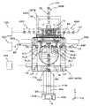
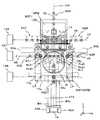
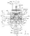
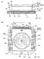
도 1 은, 제 1 실시형태에 관련된 노광 장치의 구성을 개략적으로 나타내는 도면이다.
도 2 는, 웨이퍼 스테이지를 나타내는 평면도이다.
도 3 은, 계측 스테이지를 나타내는 평면도이다.
도 4 는, 간섭계 시스템을 설명하기 위한 도면이다.
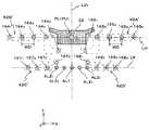
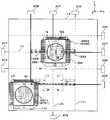
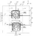
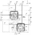
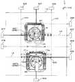
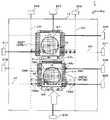
도 5 는, 스테이지 장치 및 각종 계측 장치를 나타내는 평면도이다.
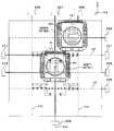
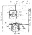
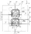
도 6 은, 인코더 시스템의 헤드, 얼라이먼트계 및 주변 노광 유닛 등의 배치를 설명하기 위한 도면이다.
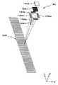
도 7 은, 다점 AF 계, 및 면위치 계측 시스템의 Z 헤드의 배치를 설명하기 위한 도면이다.
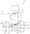
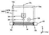
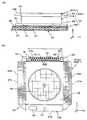
도 8 은, 주변 노광용 액티브 마스크를 설명하기 위한 도면이다.
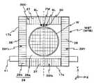
도 9(A) 및 도 9(B) 는, 각각 마이크로 미러의 온 상태 및 오프 상태를 설명하기 위한 도면이다.
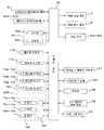
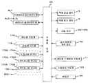
도 10 은, 도 1 의 노광 장치에 있어서의 제어계의 주요한 구성을 나타내는 블록도이다.
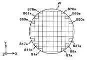
도 11 은, 웨이퍼의 쇼트 맵을 설명하기 위한 도면이다.
도 12 는, 웨이퍼의 얼라이먼트 쇼트 영역을 설명하기 위한 도면이다.
도 13 은, 주변 노광의 대상이 되는 영역을 설명하기 위한 도면이다.
도 14 는, 웨이퍼 스테이지 상의 웨이퍼에 대한 스텝·앤드·스캔 방식의 노광이 실시되고 있는 상태의 웨이퍼 스테이지 및 계측 스테이지의 상태를 나타내는 도면이다.
도 15 는, 웨이퍼의 언로딩시 (계측 스테이지가 Sec-BCHK (인터벌) 를 실시하는 위치에 도달하였을 때) 에 있어서의 양 스테이지의 상태를 나타내는 도면이다.
도 16 은, 웨이퍼의 로딩시에 있어서의 양 스테이지의 상태를 나타내는 도면이다.
도 17 은, 간섭계에 의한 스테이지 서보 제어로부터 인코더에 의한 스테이지 서보 제어로의 전환시 (웨이퍼 스테이지가 Pri-BCHK 의 전반(前半) 처리를 실시하는 위치로 이동하였을 때) 에 있어서의 양 스테이지의 상태를 나타내는 도면이다.
도 18 은, 얼라이먼트계 (AL1, AL22, AL23) 를 사용하여, 3 개의 퍼스트 얼라이먼트 쇼트 영역에 부설된 얼라이먼트 마크를 동시 검출하고 있을 때의 웨이퍼 스테이지와 계측 스테이지의 상태를 나타내는 도면이다.
도 19 는, 포커스 캘리브레이션 전반 처리를 하고 있을 때의 웨이퍼 스테이지와 계측 스테이지의 상태를 나타내는 도면이다.
도 20 은, 얼라이먼트계 (AL1, AL21 ∼ AL24) 를 사용하여, 5 개의 세컨드 얼라이먼트 쇼트 영역에 부설된 얼라이먼트 마크를 동시 검출하고 있을 때의 웨이퍼 스테이지와 계측 스테이지의 상태를 나타내는 도면이다.
도 21 은, Pri-BCHK 후반 처리 및 포커스 캘리브레이션 후반 처리 중 적어도 일방이 실시되고 있을 때의 웨이퍼 스테이지와 계측 스테이지의 상태를 나타내는 도면이다.
도 22 는, 얼라이먼트계 (AL1, AL21 ∼ AL24) 를 사용하여, 5 개의 서드 얼라이먼트 쇼트 영역에 부설된 얼라이먼트 마크를 동시 검출하고 있을 때의 웨이퍼 스테이지와 계측 스테이지의 상태를 나타내는 도면이다.
도 23 은, 얼라이먼트계 (AL1, AL22, AL23) 를 사용하여, 3 개의 포스 얼라이먼트 쇼트 영역에 부설된 얼라이먼트 마크를 동시 검출하고 있을 때의 웨이퍼 스테이지와 계측 스테이지의 상태를 나타내는 도면이다.
도 24 는, 포커스 매핑이 종료되었을 때의 웨이퍼 스테이지와 계측 스테이지의 상태를 나타내는 도면이다.
도 25(A) ∼ 도 25(F) 는, 각각 주변 노광의 진행 과정을 설명하기 위한 도면이다.
도 26 은, 주변 노광에 의해 노광된 모든 영역을 나타내는 도면이다.
도 27 은, 제 2 실시형태에 관련된 노광 장치의 구성을 개략적으로 나타내는 도면이다.
도 28 은, 웨이퍼 스테이지를 나타내는 평면도이다.
도 29 는, 도 27 의 노광 장치가 구비하는 스테이지 장치 및 간섭계의 배치를 나타내는 평면도이다.
도 30 은, 도 27 의 노광 장치가 구비하는 스테이지 장치 및 센서 유닛의 배치를 나타내는 평면도이다.
도 31 은, 인코더 헤드와 얼라이먼트계의 배치를 나타내는 평면도이다.
도 32 는, 제 2 실시형태에 관련된 노광 장치의 제어계의 주요한 구성을 나타내는 블록도이다.
도 33 은, 복수의 헤드를 각각 포함하는 복수의 인코더에 의한 웨이퍼 테이블의 XY 평면 내의 위치 계측 및 헤드의 전환 (연결) 에 대하여 설명하기 위한 도면이다.
도 34 는, 인코더 구성의 일례를 나타내는 도면이다.
도 35 는, 웨이퍼에 대한 스텝·앤드·스캔 방식의 노광이 실시되고 있을 때의 웨이퍼 스테이지 및 계측 스테이지의 상태를 나타내는 도면이다.
도 36 은, 웨이퍼의 언로딩시에 있어서의 웨이퍼 스테이지 및 계측 스테이지의 상태를 나타내는 도면이다.
도 37 은, 웨이퍼의 로딩시에 있어서의 웨이퍼 스테이지 및 계측 스테이지의 상태를 나타내는 도면이다.
도 38 은, 간섭계에 의한 스테이지 서보 제어로부터 인코더에 의한 스테이지 서보 제어로의 전환시에 있어서의 웨이퍼 스테이지 및 계측 스테이지의 상태, 그리고 인코더 헤드의 배치를 나타내는 도면이다.
도 39 는, 웨이퍼 얼라이먼트시에 있어서의 웨이퍼 스테이지 및 계측 스테이지의 상태를 설명하기 위한 도면이다.
도 40 은, 제 3 실시형태의 노광 장치가 구비하는 스테이지 장치 및 센서 유닛의 배치를 나타내는 평면도이다.
도 41 은, 제 3 실시형태에 관련된 노광 장치의 제어계의 주요한 구성을 나타내는 블록도이다.
도 42 는, 제 4 실시형태의 노광 장치의 구성을 개략적으로 나타내는 도면이다.
도 43(A) 는 도 42 의 웨이퍼 스테이지 (WST1) 를 나타내는 측면도, 도 43(B) 는 웨이퍼 스테이지 (WST1) 를 나타내는 평면도이다.
도 44(A) 는 도 42 의 웨이퍼 스테이지 (WST2) 를 나타내는 측면도, 도 44(B) 는 웨이퍼 스테이지 (WST2) 를 나타내는 평면도이다.
도 45 는, 도 42 의 웨이퍼 스테이지 장치가 구비하는 계측 시스템을 구성하는 인코더 시스템 및 면위치 계측 시스템 등의 헤드의 배치 등을 설명하기 위한 도면이다.
도 46 은, 계측 시스템을 구성하는 간섭계 시스템의 구성을 설명하기 위한 도면이다.
도 47 은, 제 2 실시형태의 노광 장치의 제어계의 주요한 구성을 나타내는 블록도이다.
도 48 은, 웨이퍼 스테이지 (WST1, WST2) 를 사용한 병행 처리 동작에 대하여 설명하기 위한 제 1 도면이다.
도 49 는, 웨이퍼 스테이지 (WST1, WST2) 를 사용한 병행 처리 동작에 대하여 설명하기 위한 제 2 도면이다.
도 50 은, 웨이퍼 스테이지 (WST1, WST2) 를 사용한 병행 처리 동작에 대하여 설명하기 위한 제 3 도면이다.
도 51 은, 웨이퍼 스테이지 (WST1, WST2) 를 사용한 병행 처리 동작에 대하여 설명하기 위한 제 4 도면이다.
도 52 는, 웨이퍼 스테이지 (WST1, WST2) 를 사용한 병행 처리 동작에 대하여 설명하기 위한 제 5 도면이다.
도 53 은, 웨이퍼 스테이지 (WST1, WST2) 를 사용한 병행 처리 동작에 대하여 설명하기 위한 제 6 도면이다.
도 54 는, 웨이퍼 스테이지 (WST1, WST2) 를 사용한 병행 처리 동작에 대하여 설명하기 위한 제 7 도면이다.
도 55 는, 웨이퍼 스테이지 (WST1, WST2) 를 사용한 병행 처리 동작에 대하여 설명하기 위한 제 8 도면이다.
도 56 은, 웨이퍼 스테이지 (WST1, WST2) 를 사용한 병행 처리 동작에 대하여 설명하기 위한 제 9 도면이다.
도 57 은, 웨이퍼 스테이지 (WST1, WST2) 를 사용한 병행 처리 동작에 대하여 설명하기 위한 제 10 도면이다.
도 58 은, 웨이퍼 스테이지 (WST1, WST2) 를 사용한 병행 처리 동작에 대하여 설명하기 위한 제 11 도면이다.
도 59 는, 웨이퍼 스테이지 (WST1, WST2) 를 사용한 병행 처리 동작에 대하여 설명하기 위한 제 12 도면이다.
도 60 은, 웨이퍼 스테이지 (WST1, WST2) 를 사용한 병행 처리 동작에 대하여 설명하기 위한 제 13 도면이다.
도 61 은, 웨이퍼 스테이지 (WST1, WST2) 를 사용한 병행 처리 동작에 대하여 설명하기 위한 제 14 도면이다.
도 62 는, 웨이퍼 스테이지 (WST1, WST2) 를 사용한 병행 처리 동작에 대하여 설명하기 위한 제 15 도면이다.
도 63 은, 웨이퍼 스테이지 (WST1, WST2) 를 사용한 병행 처리 동작에 대하여 설명하기 위한 제 16 도면이다.
도 64 는, 웨이퍼 스테이지 (WST1, WST2) 를 사용한 병행 처리 동작에 대하여 설명하기 위한 제 17 도면이다.
도 65 는, 웨이퍼 스테이지 (WST1, WST2) 를 사용한 병행 처리 동작에 대하여 설명하기 위한 제 18 도면이다.
도 66 은, 웨이퍼 스테이지 (WST1, WST2) 를 사용한 병행 처리 동작에 대하여 설명하기 위한 제 19 도면이다.
도 67 은, 웨이퍼 스테이지 (WST1, WST2) 를 사용한 병행 처리 동작에 대하여 설명하기 위한 제 20 도면이다.
도 68 은, 웨이퍼 스테이지 (WST1, WST2) 를 사용한 병행 처리 동작에 대하여 설명하기 위한 제 21 도면이다.
도 69 는, 웨이퍼 스테이지 W(ST1, WST2) 를 사용한 병행 처리 동작에 대하여 설명하기 위한 제 22 도면이다.
도 70 은, 웨이퍼 스테이지 (WST1, WST2) 를 사용한 병행 처리 동작에 대하여 설명하기 위한 제 23 도면이다.
도 71 은, 웨이퍼 스테이지 (WST1, WST2) 를 사용한 병행 처리 동작에 대하여 설명하기 위한 제 24 도면이다.
도 72 는, 웨이퍼 스테이지 (WST1, WST2) 를 사용한 병행 처리 동작에 대하여 설명하기 위한 제 25 도면이다.
도 73 은, 웨이퍼 스테이지 (WST1, WST2) 를 사용한 병행 처리 동작에 대하여 설명하기 위한 제 26 도면이다.
도 74 는, 웨이퍼 스테이지 (WST1, WST2) 를 사용한 병행 처리 동작에 대하여 설명하기 위한 제 27 도면이다.
도 75 는, 웨이퍼 스테이지 (WST1, WST2) 를 사용한 병행 처리 동작인 대하여 설명하기 위한 제 28 도면이다.
도 76 은, 웨이퍼 스테이지 (WST1, WST2) 를 사용한 병행 처리 동작에 대하여 설명하기 위한 제 29 도면이다.1 is a diagram schematically showing a configuration of an exposure apparatus according to a first embodiment.
2 is a plan view of the wafer stage.
3 is a plan view of the measurement stage.
4 is a diagram for explaining an interferometer system.
5 is a plan view of the stage device and various measurement devices.
FIG. 6 is a diagram for explaining an arrangement of a head, an alignment system, a peripheral exposure unit, and the like of the encoder system.
It is a figure for demonstrating arrangement | positioning of the Z point of a multipoint AF system and a surface position measuring system.
8 is a diagram for explaining an active mask for peripheral exposure.
9 (A) and 9 (B) are diagrams for explaining on and off states of the micromirrors, respectively.
FIG. 10 is a block diagram showing the main configuration of a control system in the exposure apparatus of FIG. 1.
11 is a diagram for explaining a short map of a wafer.
12 is a diagram for explaining an alignment short region of a wafer.
It is a figure for demonstrating the area | region used as the object of peripheral exposure.
It is a figure which shows the state of the wafer stage and the measurement stage of the state in which exposure of the step-and-scan system was performed with respect to the wafer on the wafer stage.
FIG. 15 is a diagram showing states of both stages when the wafer is unloaded (when the measurement stage reaches a position where Sec-BCHK (interval) is performed).
FIG. 16 is a diagram showing states of both stages at the time of loading of a wafer.
Fig. 17 shows the state of both stages when switching from stage servo control by an interferometer to stage servo control by an encoder (when the wafer stage has moved to a position where the front-end processing of Pri-BCHK is performed). It is a figure which shows.
FIG. 18 is a diagram illustrating the state of the wafer stage and the measurement stage when alignment marks laid in three first alignment shot regions are simultaneously detected using alignment systems AL1, AL22 , AL23 .
It is a figure which shows the state of the wafer stage and the measurement stage at the time of performing the focus calibration first half process.
FIG. 20 is a diagram illustrating the state of the wafer stage and the measurement stage when the alignment marks attached to the five second alignment short regions are simultaneously detected using the alignment systems AL1 and AL21 to AL24 .
FIG. 21: is a figure which shows the state of the wafer stage and the measurement stage when at least one of Pri-BCHK post-processing and focus calibration post-processing is performed.
FIG. 22 is a diagram illustrating a state of the wafer stage and the measurement stage when the alignment marks attached to the five third alignment shot regions are simultaneously detected using the alignment systems AL1 and AL21 to AL24 .
FIG. 23 is a diagram illustrating the state of the wafer stage and the measurement stage when alignment marks laid in three force alignment shot regions are simultaneously detected using alignment systems AL1, AL22 , AL23 .
24 is a diagram illustrating states of the wafer stage and the measurement stage when focus mapping is completed.
FIG.25 (A)-FIG.25 (F) is a figure for demonstrating the advancing process of peripheral exposure, respectively.
FIG. 26 is a diagram illustrating all regions exposed by the peripheral exposure. FIG.
FIG. 27 is a diagram schematically showing a configuration of an exposure apparatus according to a second embodiment.
28 is a plan view of the wafer stage.
FIG. 29 is a plan view illustrating an arrangement of a stage apparatus and an interferometer included in the exposure apparatus of FIG. 27.
FIG. 30 is a plan view illustrating an arrangement of a stage apparatus and a sensor unit included in the exposure apparatus of FIG. 27.
31 is a plan view showing the arrangement of the encoder head and the alignment system.
32 is a block diagram showing a main configuration of a control system of the exposure apparatus according to the second embodiment.
It is a figure for demonstrating the position measurement in the XY plane of a wafer table by a some encoder each including a some head, and switching (connection) of a head.
34 is a diagram illustrating an example of an encoder configuration.
It is a figure which shows the state of the wafer stage and the measurement stage at the time of exposure of the step-and-scan system with respect to a wafer.
36 is a diagram illustrating states of a wafer stage and a measurement stage at the time of unloading the wafer.
It is a figure which shows the state of the wafer stage and the measurement stage at the time of loading of a wafer.
FIG. 38 is a diagram illustrating the states of the wafer stage and the measurement stage and the arrangement of the encoder heads when switching from stage servo control by an interferometer to stage servo control by an encoder.
It is a figure for demonstrating the state of the wafer stage and the measurement stage at the time of wafer alignment.
40 is a plan view illustrating an arrangement of a stage device and a sensor unit included in the exposure apparatus of the third embodiment.
FIG. 41 is a block diagram showing a main configuration of a control system of the exposure apparatus according to the third embodiment. FIG.
42 is a diagram schematically illustrating a configuration of an exposure apparatus of a fourth embodiment.
FIG. 43A is a side view illustrating the wafer stage WST1 in FIG. 42, and FIG. 43B is a plan view illustrating the wafer stage WST1.
FIG. 44A is a side view showing the wafer stage WST2 in FIG. 42, and FIG. 44B is a plan view showing the wafer stage WST2.
It is a figure for demonstrating arrangement | positioning of heads, such as an encoder system and surface position measurement system which comprise the measurement system with which the wafer stage apparatus of FIG. 42 is equipped.
It is a figure for demonstrating the structure of the interferometer system which comprises a measurement system.
FIG. 47 is a block diagram showing a main configuration of a control system of the exposure apparatus of the second embodiment. FIG.
48 is a first diagram for describing the parallel processing operation using the wafer stages WST1 and WST2.
FIG. 49 is a second diagram for describing the parallel processing operation using the wafer stages WST1 and WST2.
FIG. 50 is a third view for explaining the parallel processing operation using the wafer stages WST1 and WST2.
FIG. 51 is a fourth view for explaining the parallel processing operation using the wafer stages WST1 and WST2.
52 is a fifth diagram for describing the parallel processing operation using the wafer stages WST1 and WST2.
FIG. 53 is a sixth view for explaining the parallel processing operation using the wafer stages WST1 and WST2.
54 is a seventh view for explaining the parallel processing operation using the wafer stages WST1 and WST2.
FIG. 55 is an eighth view for explaining the parallel processing operation using the wafer stages WST1 and WST2.
56 is a ninth view for explaining the parallel processing operation using the wafer stages WST1 and WST2.
FIG. 57 is a tenth view for explaining the parallel processing operation using the wafer stages WST1 and WST2.
58 is an eleventh diagram for explaining the parallel processing operation using the wafer stages WST1 and WST2.
FIG. 59 is a twelfth view for explaining the parallel processing operation using the wafer stages WST1 and WST2.
FIG. 60 is a thirteenth view for explaining a parallel processing operation using the wafer stages WST1 and WST2.
Fig. 61 is a fourteenth view for explaining the parallel processing operation using the wafer stages WST1 and WST2.
FIG. 62 is a fifteenth view for explaining the parallel processing operation using the wafer stages WST1 and WST2.
FIG. 63 is a sixteenth view for explaining the parallel processing operation using the wafer stages WST1 and WST2.
64 is a seventeenth view for explaining the parallel processing operation using the wafer stages WST1 and WST2.
FIG. 65 is an eighteenth view for explaining the parallel processing operation using the wafer stages WST1 and WST2.
66 is a nineteenth diagram for explaining the parallel processing operation using the wafer stages WST1 and WST2.
67 is a twentieth view for explaining the parallel processing operation using the wafer stages WST1 and WST2.
FIG. 68 is a twenty-first diagram for explaining a parallel processing operation using the wafer stages WST1 and WST2.
FIG. 69 is a twenty-second view for explaining a parallel processing operation using the wafer stages W (ST1, WST2). FIG.
70 is a twenty-third view for explaining the parallel processing operation using the wafer stages WST1 and WST2.
FIG. 71 is a twenty-fourth view for explaining a parallel processing operation using the wafer stages WST1 and WST2.
FIG. 72 is a twenty-fifth view for explaining the parallel processing operation using the wafer stages WST1 and WST2.
FIG. 73 is a 26th view for explaining a parallel processing operation using the wafer stages WST1 and WST2.
74 is a twenty-sixth diagram for explaining a parallel processing operation using the wafer stages WST1 and WST2.
FIG. 75 is a twenty-eighth view for explaining the parallel processing operation using the wafer stages WST1 and WST2.
FIG. 76 is a 29th view for explaining the parallel processing operation using the wafer stages WST1 and WST2.
《제 1 실시형태》&Quot; First embodiment "
이하, 본 발명의 제 1 실시형태에 대하여 도 1 ∼ 도 26 에 기초하여 설명한다.EMBODIMENT OF THE INVENTION Hereinafter, 1st Embodiment of this invention is described based on FIG.
도 1 에는, 제 1 실시형태의 노광 장치 (100) 의 구성이 개략적으로 도시되어 있다. 노광 장치 (100) 는, 스텝·앤드·스캔 방식의 투영 노광 장치, 이른바 스캐너이다. 후술하는 바와 같이 본 실시형태에서는, 투영 광학계 (PL) 가 형성되어 있고, 이하에서는, 이 투영 광학계 (PL) 의 광축 (AX) 과 평행한 방향을 Z 축 방향, 이것과 직교하는 면 내에서 레티클과 웨이퍼가 상대 주사되는 방향을 Y 축 방향, Z 축 및 Y 축과 직교하는 방향을 X 축 방향으로 하고, X 축, Y 축 및 Z 축 둘레의 회전 (경사) 방향을 각각 θx, θy 및 θz 방향으로 하여 설명한다.In FIG. 1, the structure of the
노광 장치 (100) 는, 조명계 (10), 레티클 스테이지 (RST), 투영 유닛 (PU), 웨이퍼 스테이지 (WST) 및 계측 스테이지 (MST) 를 갖는 스테이지 장치 (50), 및 이들의 제어계 등을 구비하고 있다. 도 1 에 있어서, 웨이퍼 스테이지 (WST) 상에는 웨이퍼 (W) 가 탑재되어 있다.The
조명계 (10) 는, 예를 들어 미국 특허 출원 공개 제2003/0025890호 명세서 등에 개시된 바와 같이, 광원과, 옵티컬 인터그레이터를 갖는 조도 균일화 광학계, 및 레티클 블라인드 (모두 도시 생략) 를 갖는 조명 광학계를 포함한다. 조명계 (10) 는, 레티클 블라인드 (마스킹 시스템) 에 의해 규정된 레티클 (R) 상의 슬릿 형상의 조명 영역 (IAR) 을 조명광 (노광광) (IL) 에 의해 거의 균일한 조도로 조명한다. 여기서, 조명광 (IL) 으로서, 예를 들어 ArF 엑시머 레이저광 (파장 193 ㎚) 이 사용된다.The
레티클 스테이지 (RST) 상에는, 회로 패턴 등이 그 패턴면 (도 1 에 있어서의 하면) 에 형성된 레티클 (R) 이 예를 들어 진공 흡착에 의해 고정되어 있다. 레티클 스테이지 (RST) 는, 예를 들어 리니어 모터 등을 포함하는 레티클 스테이지 구동계 (11) (도 1 에서는 도시 생략, 도 10 참조) 에 의해 XY 평면 내에서 미소 구동할 수 있음과 함께, 주사 방향 (도 1 에 있어서의 지면 내 좌우 방향인 Y 축 방향) 으로 소정의 주사 속도로 구동할 수 있도록 되어 있다.On the reticle stage RST, the reticle R in which a circuit pattern etc. were formed in the pattern surface (lower surface in FIG. 1) is fixed by vacuum suction, for example. The reticle stage RST can be minutely driven in the XY plane by, for example, a reticle stage drive system 11 (not shown in FIG. 1, see FIG. 10) including a linear motor, and the scanning direction ( It is possible to drive at a predetermined scanning speed in the Y axis direction, which is the left and right direction in the page in FIG. 1.
레티클 스테이지 (RST) 의 XY 평면 내의 위치 정보 (θz 방향의 위치 (이하에서는, 적절히 θz 회전 (혹은 θz 회전량) 또는 요잉 (혹은 요잉량) 이라고도 기술한다) 의 정보를 포함한다) 는, 레티클 레이저 간섭계 (이하 「레티클 간섭계」라고 한다) (116) 에 의해, 이동경 (15) (실제로는, Y 축 방향과 직교하는 반사면을 갖는 Y 이동경 (혹은, 레트로 리플렉터) 과 X 축 방향과 직교하는 반사면을 갖는 X 이동경이 형성되어 있다) 을 통해, 예를 들어 0.25 ㎚ 정도의 분해능으로 항상 검출된다. 레티클 간섭계 (116) 의 계측값은 주제어 장치 (20) (도 1 에서는 도시 생략, 도 10 참조) 로 보내진다.The positional information in the XY plane of the reticle stage RST (the position in the θz direction (hereinafter including the information of θz rotation (or θz rotation amount) or yawing (or yaw amount) as appropriate)) is a reticle laser. The interferometer (hereinafter referred to as a "reticle interferometer") 116 allows the moving mirror 15 (actually a Y moving mirror (or retro reflector) having a reflective surface orthogonal to the Y axis direction) and a half perpendicular to the X axis direction. An X moving mirror having a slope is formed), and is always detected at a resolution of, for example, about 0.25 nm. The measured value of the
투영 유닛 (PU) 은, 레티클 스테이지 (RST) 의 도 1 에 있어서의 하방에 배치되어 있다. 투영 유닛 (PU) 은, 경통 (40) 과, 경통 (40) 내에 저장된 투영 광학계 (PL) 를 포함한다. 투영 광학계 (PL) 로서, 예를 들어 Z 축 방향과 평행한 광축 (AX) 을 따라 배열되는 복수의 광학 소자 (렌즈 엘리먼트) 로 이루어지는 굴절 광학계가 사용되고 있다. 투영 광학계 (PL) 는, 예를 들어 양측 텔레센트릭이고, 소정의 투영 배율 (예를 들어 1/4, 1/5 또는 1/8 등) 을 갖는다. 이 때문에, 조명계 (10) 에 의해 레티클 (R) 상의 조명 영역 (IAR) 이 조명되면, 투영 광학계 (PL) 의 제 1 면 (물체면) 과 패턴면이 거의 일치하여 배치되는 레티클 (R) 을 통과한 조명광 (IL) 에 의해, 투영 광학계 (PL) (투영 유닛 (PU)) 를 통해 그 조명 영역 (IAR) 내의 레티클 (R) 의 회로 패턴의 축소 이미지 (회로 패턴 일부의 축소 이미지) 가, 투영 광학계 (PL) 의 제 2 면 (이미지면) 측에 배치되는, 표면에 레지스트 (감응제) 가 도포된 웨이퍼 (W) 상의 상기 조명 영역 (IAR) 에 공액인 영역 (이하, 노광 영역이라고도 한다) (IA) 에 형성된다. 그리고, 레티클 스테이지 (RST) 와 웨이퍼 스테이지 (WST) 의 동기 구동에 의해, 조명 영역 (IAR) (조명광 (IL)) 에 대하여 레티클 (R) 을 주사 방향 (Y 축 방향) 으로 상대 이동시킴과 함께, 노광 영역 (IA) (조명광 (IL)) 에 대하여 웨이퍼 (W) 를 주사 방향 (Y 축 방향) 으로 상대 이동시킴으로써, 웨이퍼 (W) 상의 1 개의 쇼트 영역 (구획 영역) 의 주사 노광이 실시되어, 그 쇼트 영역에 레티클 (R) 의 패턴이 전사된다. 즉, 본 실시형태에서는 조명계 (10), 레티클 (R) 및 투영 광학계 (PL) 에 의해 웨이퍼 (W) 상에 패턴이 생성되고, 조명광 (IL) 에 의한 웨이퍼 (W) 상의 감응층 (레지스트층) 의 노광에 의해 웨이퍼 (W) 상에 그 패턴이 형성된다.The projection unit PU is disposed below the reticle stage RST in Fig. The projection unit PU includes the
본 실시형태의 노광 장치 (100) 에는, 액침 방식의 노광을 실시하기 위해서 국소 액침 장치 (8) 가 형성되어 있다. 국소 액침 장치 (8) 는, 예를 들어 액체 공급 장치 (5), 액체 회수 장치 (6) (모두 도 1 에서는 도시 생략, 도 10 참조), 액체 공급관 (31A), 액체 회수관 (31B) 및 노즐 유닛 (32) 등을 포함한다. 노즐 유닛 (32) 은, 도 1 에 도시된 바와 같이, 투영 광학계 (PL) 를 구성하는 가장 이미지면측 (웨이퍼 (W) 측) 에 가까운 광학 소자, 여기서는 렌즈 (이하 「선단 렌즈」라고도 한다) (191) 를 유지하는 경통 (40) 의 하단부 주위를 둘러싸도록, 투영 유닛 (PU) 을 유지하는 도시가 생략된 메인 프레임에 매달려 지지되어 있다. 본 실시형태에서는, 노즐 유닛 (32) 은, 도 1 에 도시된 바와 같이, 그 하단면이 선단 (先端) 렌즈 (191) 의 하단면과 거의 동일한 면으로 설정되어 있다. 또한, 노즐 유닛 (32) 은, 액체 (Lq) 의 공급구 및 회수구와, 웨이퍼 (W) 가 대향하여 배치되고, 또한 회수구가 형성되는 하면과, 액체 공급관 (31A) 및 액체 회수관 (31B) 과 각각 접속되는 공급 유로 및 회수 유로를 구비하고 있다. 액체 공급관 (31A) 과 액체 회수관 (31B) 은, 도 5 에 도시된 바와 같이, 평면에서 볼 때 (상방에서 볼 때) X 축 방향 및 Y 축 방향에 대하여 대략 45°경사지고, 투영 유닛 (PU) 의 중심 (투영 광학계 (PL) 의 광축 (AX), 본 실시형태에서는 전술한 노광 영역 (IA) 의 중심과도 일치) 을 통과하고 또한 Y 축과 평행한 직선 (기준축) (LV0) 에 관하여 대칭인 배치로 되어 있다.The local
액체 공급관 (31A) 은 액체 공급 장치 (5) (도 1 에서는 도시 생략, 도 10 참조) 에, 액체 회수관 (31B) 은 액체 회수 장치 (6) (도 1 에서는 도시 생략, 도 10 참조) 에 접속되어 있다. 여기서, 액체 공급 장치 (5) 에는, 액체를 저장하는 탱크, 가압 펌프, 온도 제어 장치, 액체의 유량을 제어하기 위한 밸브 등이 구비되어 있다. 액체 회수 장치 (6) 에는, 회수한 액체를 저장하는 탱크, 흡인 펌프, 액체의 유량을 제어하기 위한 밸브 등이 구비되어 있다.The
주제어 장치 (20) (도 10 참조) 는, 액체 공급 장치 (5) 를 제어하여, 액체 공급관 (31A) 을 통해 선단 렌즈 (191) 와 웨이퍼 (W) 사이에 액체 (Lq) 를 공급함과 함께, 액체 회수 장치 (6) 를 제어하여, 액체 회수관 (31B) 을 통해 선단 렌즈 (191) 와 웨이퍼 (W) 사이로부터 액체 (Lq) 를 회수한다. 이 때, 주제어 장치 (20) 는, 공급되는 액체 (Lq) 의 양과 회수되는 액체 (Lq) 의 양이 항상 동일해지도록 액체 공급 장치 (5) 와 액체 회수 장치 (6) 를 제어한다. 따라서, 선단 렌즈 (191) 와 웨이퍼 (W) 사이에는, 일정량의 액체 (Lq) (도 1 참조) 가 항상 교체되어 유지되고, 그것에 의해 액침 영역 (14) (도 14 등 참조) 이 형성된다. 또한, 투영 유닛 (PU) 의 하방에 후술하는 계측 스테이지 (MST) 가 위치하는 경우에도, 동일하게 선단 렌즈 (191) 와 계측 테이블 사이에 액침 영역 (14) 을 형성할 수 있다.The main controller 20 (see FIG. 10) controls the
본 실시형태에서는, 상기 액체로서 ArF 엑시머 레이저광 (파장 193 ㎚ 의 광) 이 투과하는 순수 (이하, 특별히 필요한 경우를 제외하고 단순히 「물」이라고 기술한다) 를 사용하는 것으로 한다. 또한, ArF 엑시머 레이저광에 대한 물의 굴절률 n 은 대략 1.44 이고, 물 속에서는, 조명광 (IL) 의 파장은 193 ㎚ × 1/n = 약 134 ㎚ 로 단파장화된다.In the present embodiment, pure water (hereinafter, simply described as “water”) through which ArF excimer laser light (wavelength of 193 nm) transmits is used as the liquid. In addition, the refractive index n of water with respect to the ArF excimer laser light is approximately 1.44, and in water, the wavelength of the illumination light IL is shortened to 193 nm x 1 / n = about 134 nm.
스테이지 장치 (50) 는, 도 1 에 도시된 바와 같이, 베이스반 (12) 의 상방에 배치된 웨이퍼 스테이지 (WST) 와 계측 스테이지 (MST), 이들 스테이지 (WST, MST) 의 위치 정보를 계측하는 계측 시스템 (200) (도 10 참조), 및 스테이지 (WST, MST) 를 구동하는 스테이지 구동계 (124) (도 10 참조) 등을 구비하고 있다. 계측 시스템 (200) 은, 도 10 에 도시된 바와 같이, 간섭계 시스템 (118), 인코더 시스템 (150) 및 면위치 계측 시스템 (180) 등을 포함한다.As shown in FIG. 1, the
웨이퍼 스테이지 (WST) 및 계측 스테이지 (MST) 는, 각각의 저면에 고정된 도시가 생략된 비접촉 베어링, 예를 들어 에어 베어링에 의해, 수 ㎛ 정도의 클리어런스를 사이에 두고 베이스반 (12) 상에 지지되어 있다. 또한, 스테이지 (WST, MST) 는, 예를 들어 리니어 모터 등을 포함하는 스테이지 구동계 (124) (도 10 참조) 에 의해 XY 평면 내에서 독립적으로 구동할 수 있다.The wafer stage WST and the measurement stage MST are provided on the
웨이퍼 스테이지 (WST) 는, 스테이지 본체 (91) 와, 그 스테이지 본체 (91) 상에 탑재된 웨이퍼 테이블 (WTB) 을 포함한다. 웨이퍼 테이블 (WTB) 및 스테이지 본체 (91) 는, 예를 들어 리니어 모터 및 Z·레벨링 기구 (보이스 코일 모터 등을 포함한다) (모두 도시 생략) 를 포함하는 구동계에 의해, 베이스반 (12) 에 대하여 6 자유도 방향 (X, Y, Z, θx, θy, θz) 으로 구동할 수 있게 구성되어 있다.The wafer stage WST includes a stage
웨이퍼 테이블 (WTB) 상면의 중앙에는, 웨이퍼 (W) 를 진공 흡착 등에 의해 유지하는 웨이퍼 홀더 (도시 생략) 가 형성되어 있다. 웨이퍼 홀더 (웨이퍼의 탑재 영역) 의 외측에는, 도 2 에 도시된 바와 같이, 웨이퍼 홀더보다 한층 더 큰 원형 개구가 중앙에 형성되고, 또한 직사각형 형상의 외형 (윤곽) 을 갖는 플레이트 (발액판) (28) 가 형성되어 있다. 이 플레이트 (28) 의 표면은, 액체 (Lq) 에 대하여 발액화 처리되어 있다. 또한 플레이트 (28) 는, 그 표면의 전부 (혹은 일부) 가 웨이퍼 (W) 의 표면과 동일한 면이 되도록 설치되어 있다.In the center of the upper surface of the wafer table WTB, a wafer holder (not shown) for holding the wafer W by vacuum suction or the like is formed. Outside the wafer holder (wafer mounting area), as shown in Fig. 2, a plate (liquid plate) having a larger circular opening in the center and having a rectangular shape (contour) in the center ( 28) is formed. The surface of this
플레이트 (28) 는, 중앙에 상기 개구가 형성된 직사각형의 외형 (윤곽) 을 갖는 제 1 발액 영역 (28a) 과, 그 제 1 발액 영역 (28a) 의 주위에 형성된 직사각형 프레임 형상의 제 2 발액 영역 (28b) 을 갖고 있다. 또한 본 실시형태에서는, 전술한 바와 같이 액체 (Lq) 로서 물을 사용하기 때문에, 이하에서는 제 1 및 제 2 발액 영역 (28a, 28b) 을 각각 제 1 및 제 2 발수판 (28a, 28b) 이라고도 한다.The
제 1 발수판 (28a) 의 +Y 측 단부에는 계측 플레이트 (30) 가 형성되어 있다. 이 계측 플레이트 (30) 에는, 중앙에 기준 마크 (FM) 가 형성되고, 그 기준 마크 (FM) 를 사이에 두도록 1 쌍의 공간 이미지 계측 슬릿 패턴 (슬릿 형상의 계측용 패턴) (SL) 이 형성되어 있다. 그리고, 각 공간 이미지 계측 슬릿 패턴 (SL) 에 대응하여, 그들을 투과한 조명광 (IL) 을 웨이퍼 스테이지 (WST) 의 외부 (후술하는 계측 스테이지 (MST) 에 형성되는 수광계) 로 유도하기 위한 송광계 (도시 생략) 가 형성되어 있다.The
제 2 발수판 (28b) 에는, 그 상면의 X 축 방향 (도 2 에 있어서의 지면 내 좌우 방향) 의 일측과 타측의 영역에 Y 스케일 (39Y1, 39Y2) 이 각각 형성되어 있다. Y 스케일 (39Y1, 39Y2) 은 각각, 예를 들어 X 축 방향을 길이 방향으로 하는 격자선 (38) 이 소정 피치로 Y 축과 평행한 방향 (Y 축 방향) 을 따라 배치되는, Y 축 방향을 주기 방향으로 하는 반사형 격자 (예를 들어 회절 격자) 에 의해 구성되어 있다.In the second
동일하게, 제 2 발수판 (28b) 의 상면에 있어서의 Y 축 방향 (도 2 에 있어서의 지면 내 상하 방향) 의 일측과 타측의 영역에는 X 스케일 (39X1, 39X2) 이 각각 형성되어 있다. X 스케일 (39X1, 39X2) 은 각각, 예를 들어 Y 축 방향을 길이 방향으로 하는 격자선 (37) 이 소정 피치로 X 축과 평행한 방향 (X 축 방향) 을 따라 배치되는, X 축 방향을 주기 방향으로 하는 반사형 격자 (예를 들어 회절 격자) 에 의해 구성되어 있다. 각 스케일은, 예를 들어 박판 형상의 유리에 상기 회절 격자 눈금이, 예를 들어 138 ㎚ ∼ 4 ㎛ 사이의 피치, 예를 들어 1 ㎛ 피치 간격으로 제조되어 있다. 이들 스케일은 전술한 발액막 (발수막) 으로 덮여 있다. 또한 도 2 에서는, 도시의 편의상, 격자의 피치는 실제 피치에 비해 현격히 넓게 도시되어 있다. 그 밖의 도면에서도 동일하다. 또한, 회절 격자를 보호하기 위해서, 발수성을 구비한 저열팽창률의 유리판에 의해, 그 표면이 웨이퍼의 표면과 동일한 높이 (면위치) 가 되도록 하여 회절 격자를 커버해도 된다. 여기서 유리판으로는, 두께가 웨이퍼와 동일한 정도, 예를 들어 두께 1 ㎜ 의 것을 사용할 수 있다.Similarly, X scales 39X1 and 39X2 are formed in one region and the other region of the Y-axis direction (up and down direction in the paper surface in FIG. 2) on the upper surface of the second
또한, 각 스케일의 끝 부근에는, 후술하는 인코더 헤드와 스케일 사이의 상대 위치를 결정하기 위한, 도시가 생략된 위치 맞춤 패턴이 각각 형성되어 있다. 이 위치 맞춤 패턴은, 예를 들어 반사율이 상이한 격자선으로 구성되고, 이 위치 맞춤 패턴 상을 인코더 헤드가 주사하면, 인코더 출력 신호의 강도가 변화된다. 그래서, 미리 임계값을 정해 두고, 출력 신호의 강도가 그 임계값을 초과하는 위치를 검출한다. 이 검출된 위치를 기준으로 인코더 헤드와 스케일 사이의 상대 위치를 설정한다.Moreover, near the end of each scale, the alignment pattern which illustration is abbreviate | omitted for determining the relative position between the encoder head and scale mentioned later is formed, respectively. This alignment pattern is comprised, for example with the grating line from which a reflectance differs, and when an encoder head scans on this alignment pattern, the intensity of an encoder output signal changes. Thus, a threshold value is determined in advance, and a position where the intensity of the output signal exceeds the threshold value is detected. The relative position between the encoder head and the scale is set based on this detected position.
웨이퍼 테이블 (WTB) 의 -Y 단면 (端面), -X 단면에는, 도 2 및 도 4 등에 도시된 바와 같이, 후술하는 간섭계 시스템에서 사용되는 반사면 (17a), 반사면 (17b) 이 형성되어 있다.In the -Y cross section and the -X cross section of the wafer table WTB, as shown in FIGS. 2 and 4, the reflecting
계측 스테이지 (MST) 는, 도 1 에 도시된 바와 같이, 도시가 생략된 리니어 모터 등에 의해 XY 평면 내에서 구동되는 스테이지 본체 (92) 와, 스테이지 본체 (92) 상에 탑재된 계측 테이블 (MTB) 을 갖고 있다. 계측 스테이지 (MST) 는, 도시가 생략된 구동계에 의해 베이스반 (12) 에 대하여 적어도 3 자유도 방향 (X, Y, θz) 으로 구동할 수 있게 구성되어 있다.As shown in FIG. 1, the measurement stage MST includes a stage
또한 도 10 에서는, 웨이퍼 스테이지 (WST) 의 구동계와 계측 스테이지 (MST) 의 구동계를 포함하여 스테이지 구동계 (124) 로서 도시되어 있다.In addition, in FIG. 10, it shows as the
계측 테이블 (MTB) (및 스테이지 본체 (92)) 에는 각종 계측용 부재가 형성되어 있다. 이 계측용 부재로는, 예를 들어 도 3 에 도시된 바와 같이, 조도 불균일 센서 (94), 공간 이미지 계측기 (96), 파면 수차 계측기 (98), 조도 모니터 (도시 생략) 등이 형성되어 있다. 또한 스테이지 본체 (92) 에는, 전술한 1 쌍의 송광계 (도시 생략) 에 대향하는 배치로 1 쌍의 수광계 (도시 생략) 가 형성되어 있다. 본 실시형태에서는, 웨이퍼 스테이지 (WST) 와 계측 스테이지 (MST) 가 Y 축 방향에 관하여 소정 거리 이내로 근접한 상태 (접촉 상태를 포함한다) 에서, 웨이퍼 스테이지 (WST) 상의 계측 플레이트 (30) 의 각 공간 이미지 계측 슬릿 패턴 (SL) 을 투과한 조명광 (IL) 을 각 송광계 (도시 생략) 에 의해 안내하고, 계측 스테이지 (MST) 내의 각 수광계 (도시 생략) 의 수광 소자에 의해 수광하는 공간 이미지 계측 장치 (45) (도 10 참조) 가 구성된다.Various measurement members are formed on the measurement table MTB (and the stage main body 92). As this measuring member, for example, as shown in FIG. 3, the
계측 테이블 (MTB) 의 -Y 측 단면에는, 도 3 에 도시된 바와 같이, 피듀셜 바 (이하 「FD 바」라고 약기한다) (46) 가 X 축 방향으로 연장되어 있다. 이 FD 바 (46) 는, 풀 키네마틱 마운트 구조에 의해, 계측 스테이지 (MST) 상에 키네마틱으로 지지되어 있다. FD 바 (46) 는 원기(原器) (계측 기준) 가 되기 때문에, 저열팽창률의 광학 유리 세라믹스, 예를 들어 쇼트사의 제로듀아 (상품명) 등이 그 소재로서 채용되고 있다. FD 바 (46) 의 길이 방향의 일측과 타측의 단부 근방에는, 센터 라인 (CL) 에 관하여 대칭인 배치로 Y 축 방향을 주기 방향으로 하는 기준 격자 (예를 들어 회절 격자) (52) 가 각각 형성되어 있다. 또한, FD 바 (46) 의 상면에는 복수의 기준 마크 (M) 가 형성되어 있다. 각 기준 마크 (M) 로는, 후술하는 프라이머리 얼라이먼트계, 세컨더리 얼라이먼트계에 의해 검출할 수 있는 치수의 2 차원 마크가 사용되고 있다. 또한, FD 바 (46) 의 표면 및 계측 테이블 (MTB) 의 표면도 발액막 (발수막) 으로 덮여 있다.On the -Y side cross section of the measurement table MTB, as shown in FIG. 3, a physical bar (hereinafter abbreviated as "FD bar") 46 extends in the X-axis direction. This
계측 테이블 (MTB) 의 +Y 측 단면 및 -X 측 단면에는, 웨이퍼 테이블 (WTB) 과 동일한 반사면 (19a) 및 반사면 (19b) 이 형성되어 있다 (도 3 참조).The reflecting
본 실시형태의 노광 장치 (100) 에서는, 도 6 에 도시된 바와 같이, 전술한 기준축 (LV0) 상에서, 투영 유닛 (PU) 의 중심 (투영 광학계 (PL) 의 광축 (AX)) 으로부터 -Y 측으로 소정 거리 떨어진 위치에 검출 중심을 갖는 프라이머리 얼라이먼트계 (AL1) 가 형성되어 있다. 프라이머리 얼라이먼트계 (AL1) 는, 도시가 생략된 메인 프레임의 하면에 고정되어 있다. 프라이머리 얼라이먼트계 (AL1) 를 사이에 두고 X 축 방향의 일측과 타측에는, 기준축 (LV0) 에 관하여 거의 대칭으로 검출 중심이 배치되는 세컨더리 얼라이먼트계 (AL21, AL22 와 AL23, AL24) 가 각각 형성되어 있다. 세컨더리 얼라이먼트계 (AL21 ∼ AL24) 는, 도시가 생략된 가동식 지지 부재를 통해 메인 프레임 (도시 생략) 의 하면에 고정되어 있고, 구동 기구 (601 ∼ 604) (도 10 참조) 를 사용하여, X 축 방향에 관하여 그들 검출 영역의 상대 위치가 조정 가능하게 되어 있다. 또한, 도 6 등에 도시된 프라이머리 얼라이먼트계 (AL1) 의 검출 중심을 통과하는 X 축과 평행한 직선 (기준축) (LA) 은, 후술하는 간섭계 (127) 로부터의 측장 빔 (B6) 의 광축과 일치한다.In the
본 실시형태에서는, 각 얼라이먼트계 (AL1, AL21 ∼ AL24) 로서, 예를 들어 화상 처리 방식의 FIA (Field Image Alig㎚ent) 계가 사용되고 있다. 얼라이먼트계 (AL1, AL21 ∼ AL24) 의 각각으로부터의 촬상 신호는, 도시가 생략된 신호 처리계를 통해 주제어 장치 (20) 에 공급된다.In this embodiment, as each of the alignment systems(AL1, AL2 1 ~ AL2 4 ), for example, has been used boundaries FIA (Field Image Alig㎚ent) of the image processing method. The imaging signals from each of the alignment systems AL1 and AL21 to AL24 are supplied to the
다음으로, 웨이퍼 스테이지 (WST) 및 계측 스테이지 (MST) 의 위치 정보를 계측하는 간섭계 시스템 (118) (도 10 참조) 의 구성 등에 대하여 설명한다.Next, the structure of the interferometer system 118 (refer FIG. 10) etc. which measure the positional information of the wafer stage WST and the measurement stage MST is demonstrated.
간섭계 시스템 (118) 은, 도 4 에 도시된 바와 같이, 웨이퍼 스테이지 (WST) 의 위치 계측용 Y 간섭계 (16), X 간섭계 (126, 127, 128) 및 Z 간섭계 (43A, 43B), 그리고 계측 스테이지 (MST) 의 위치 계측용 Y 간섭계 (18) 및 X 간섭계 (130) 등을 포함한다. Y 간섭계 (16) 및 3 개의 X 간섭계 (126, 127, 128) 는, 웨이퍼 테이블 (WTB) 의 반사면 (17a, 17b) 에 각각 간섭계 빔 (측장 빔) (B4 (B41, B42), B5 (B51, B52), B6, B7) 을 조사한다. 그리고, Y 간섭계 (16) 및 3 개의 X 간섭계 (126, 127, 128) 는 각각의 반사광을 수광하고, 웨이퍼 스테이지 (WST) 의 XY 평면 내의 위치 정보를 계측하여, 이 계측한 위치 정보를 주제어 장치 (20) 에 공급한다.The
여기서, 예를 들어 X 간섭계 (126) 는, 투영 광학계 (PL) 의 광축 (AX) (본 실시형태에서는 전술한 노광 영역 (IA) 의 중심과도 일치) 을 통과하고 또한 X 축과 평행한 직선 (기준축 (LH) (도 5 등 참조)) 에 관하여 대칭인 1 쌍의 측장 빔 (B51, B52) 을 포함하는 적어도 3 개의 X 축과 평행한 측장 빔을 반사면 (17b) 에 조사한다. 또한 Y 간섭계 (16) 는, 전술한 기준축 (LV0) 에 관하여 대칭인 1 쌍의 측장 빔 (B41, B42 및 B3) (도 1 참조) 을 포함하는 적어도 3 개의 Y 축과 평행한 측장 빔을 반사면 (17a), 및 후술하는 이동경 (41) 에 조사한다. 이와 같이 본 실시형태에서는, 상기 각 간섭계로서, 일부 (예를 들어 간섭계 (128)) 를 제외하고 측장축을 복수 갖는 다축 간섭계가 사용되고 있다. 그래서, 주제어 장치 (20) 는, Y 간섭계 (16) 와 X 간섭계 (126 또는 127) 의 계측 결과에 기초하여, 웨이퍼 테이블 (WTB) (웨이퍼 스테이지 (WST)) 의 X, Y 위치에 추가하여, θx 방향의 위치 (이하, 적절히 θx 회전 (혹은 θx 회전량) 또는 피칭 (혹은 피칭량) 이라고도 기술한다), θy 방향의 위치 (이하, 적절히 θy 회전 (혹은 θy 회전량) 또는 롤링 (혹은 롤링량) 이라고도 기술한다) 및 θz 회전 (즉 요잉량) 도 산출할 수 있다.Here, for example, the
또한 도 1 에 도시된 바와 같이, 스테이지 본체 (91) 의 -Y 측 측면에, 오목 형상의 반사면을 갖는 이동경 (41) 이 장착되어 있다. 이동경 (41) 은, 도 2 에서 알 수 있는 바와 같이, X 축 방향의 길이가 웨이퍼 테이블 (WTB) 의 반사면 (17a) 보다 길게 설정되어 있다.In addition, as shown in Fig. 1, a moving
이동경 (41) 에 대향하여 1 쌍의 Z 간섭계 (43A, 43B) 가 형성되어 있다 (도 1 및 도 4 참조). Z 간섭계 (43A, 43B) 는, 이동경 (41) 을 통해, 예를 들어 투영 유닛 (PU) 을 지지하는 메인 프레임 (도시 생략) 에 고정된 고정경 (47A, 47B) 에 각각 2 개의 측장 빔 (B1, B2) 을 조사한다. 그리고, 각각의 반사광을 수광하여, 측장 빔 (B1, B2) 의 광로 길이를 계측한다. 그 결과로부터, 주제어 장치 (20) 는 웨이퍼 스테이지 (WST) 의 4 자유도 (Y, Z, θy, θz) 방향의 위치를 산출한다.A pair of
본 실시형태에서는, 웨이퍼 스테이지 (WST) (웨이퍼 테이블 (WTB)) 의 XY 평면 내의 위치 (θz 방향의 회전 정보를 포함한다) 는, 주로 후술하는 인코더 시스템을 사용하여 계측된다. 간섭계 시스템 (118) 은, 웨이퍼 스테이지 (WST) 가 인코더 시스템의 계측 영역 밖 (예를 들어 도 5 등에 도시된 언로딩 포지션 (UP) 및 로딩 포지션 (LP) 부근) 에 위치할 때에 사용된다. 또한, 인코더 시스템의 계측 결과의 장기적 변동 (예를 들어 스케일의 시간 경과적인 변형 등에 의한다) 을 보정 (교정) 하는 경우, 혹은 인코더 시스템의 출력 이상시의 백업용 등으로서 보조적으로 사용된다. 물론, 간섭계 시스템 (118) 과 인코더 시스템을 병용하여 웨이퍼 스테이지 (WST) (웨이퍼 테이블 (WTB)) 의 위치를 제어하기로 해도 된다.In the present embodiment, the position (including rotation information in the θz direction) in the XY plane of the wafer stage WST (wafer table WTB) is mainly measured using an encoder system described later. The
간섭계 시스템 (118) 의 Y 간섭계 (18), X 간섭계 (130) 는, 도 4 에 도시된 바와 같이, 계측 테이블 (MTB) 의 반사면 (19a, 19b) 에 간섭계 빔 (측장 빔) 을 조사하고, 각각의 반사광을 수광함으로써, 계측 스테이지 (MST) 의 위치 정보 (예를 들어 적어도 X 축 및 Y 축 방향의 위치와 θz 방향의 회전 정보를 포함한다) 를 계측하고, 그 계측 결과를 주제어 장치 (20) 에 공급한다.The
다음으로, 웨이퍼 스테이지 (WST) 의 XY 평면 내의 위치 정보 (θz 방향의 회전 정보를 포함한다) 를 계측하는 인코더 시스템 (150) (도 10 참조) 의 구성 등에 대하여 설명한다. 인코더 시스템 (150) 의 주된 구성은, 예를 들어 미국 특허 출원 공개 제2008/0088843호 명세서 등에 개시되어 있다.Next, the structure etc. of the encoder system 150 (refer FIG. 10) which measures the position information (including rotation information of (theta) z direction) in the XY plane of the wafer stage WST is demonstrated. The main configuration of
노광 장치 (100) 에서는, 도 5 에 도시된 바와 같이, 노즐 유닛 (32) 의 +X 측, +Y 측, -X 측, 및 프라이머리 얼라이먼트계 (AL1) 의 -Y 측에, 4 개의 헤드 유닛 (62A, 62B, 62C 및 62D) 이 각각 배치되어 있다. 또한, 헤드 유닛 (62C, 62A) 각각의 -Y 측이고 또한 프라이머리 얼라이먼트계 (AL1) 와 거의 동일한 Y 위치에, 헤드 유닛 (62E, 62F) 이 각각 형성되어 있다. 헤드 유닛 (62A ∼ 62F) 은, 지지 부재를 통해, 투영 유닛 (PU) 을 유지하는 메인 프레임 (도시 생략) 에 매달린 상태로 고정되어 있다.In the
헤드 유닛 (62A) 은, 도 6 에 도시된 바와 같이 노즐 유닛 (32) 의 +X 측에 배치되고, X 축 방향을 따라 전술한 기준축 (LH) 상에 간격 (WD) 으로 배치된 복수 (여기서는 4 개) 의 Y 헤드 (652 ∼ 655) 와, 기준축 (LH) 으로부터 -Y 방향으로 소정 거리 떨어진 노즐 유닛 (32) 의 -Y 측의 위치에 배치된 Y 헤드 (651) 를 구비하고 있다. 여기서, Y 헤드 (651, 652) 의 X 축 방향의 간격도 WD 와 거의 동일하게 설정되어 있다. 헤드 유닛 (62C) 은, 도 6 에 도시된 바와 같이, 헤드 유닛 (62A) 과 좌우 대칭으로 구성되고, 전술한 기준축 (LV0) 에 관하여 대칭으로 배치되어 있다. 헤드 유닛 (62C) 은, Y 헤드 (655 ∼ 651) 와, 기준축 (LV0) 에 관하여 대칭으로 배치된 5 개의 Y 헤드 (641 ∼ 645) 를 구비하고 있다. 이하에서는, 적절히 Y 헤드 (651 ∼ 655, 641 ∼ 645) 를 각각 Y 헤드 (65, 64) 라고도 기술한다.The
헤드 유닛 (62A) 은, 전술한 Y 스케일 (39Y1) 을 사용하여, 웨이퍼 스테이지 (WST) (웨이퍼 테이블 (WTB)) 의 Y 축 방향의 위치 (Y 위치) 를 계측하는 다안 (多眼) (여기서는 5 안) 의 Y 리니어 인코더 (이하, 적절히 「Y 인코더」 또는 「인코더」라고 약기한다) (70A) (도 10 참조) 를 구성한다. 동일하게, 헤드 유닛 (62C) 은, 전술한 Y 스케일 (39Y2) 을 사용하여, 웨이퍼 스테이지 (WST) (웨이퍼 테이블 (WTB)) 의 Y 위치를 계측하는 다안 (여기서는 5 안) 의 Y 인코더 (70C) (도 10 참조) 를 구성한다. 여기서, 헤드 유닛 (62C, 62A) 이 각각 구비하는 5 개의 Y 헤드 (64i, 65j ; i, j = 1 ∼ 5) 중 인접하는 Y 헤드 (보다 정확하게는, 각 Y 헤드가 발하는 계측 빔의 스케일 상의 조사점) 의 X 축 방향의 간격 (WD) 은, Y 스케일 (39Y2, 39Y1) 의 X 축 방향의 폭 (보다 정확하게는, 격자선 (38) 의 길이) 보다 약간 좁게 설정되어 있다. 따라서, 노광시 등에는, 각각 5 개의 Y 헤드 (65j, 64i) 중 적어도 각 1 개의 헤드가 항상 대응하는 Y 스케일 (39Y1, 39Y2) 에 대향한다.The
헤드 유닛 (62B) 은, 도 6 에 도시된 바와 같이, 노즐 유닛 (32) (투영 유닛 (PU)) 의 +Y 측에 배치되고, 전술한 기준축 (LV0) 상에 Y 축 방향을 따라 간격 (WD) 으로 배치된 복수, 여기서는 4 개의 X 헤드 (665 ∼ 668) 를 구비하고 있다. 또한 헤드 유닛 (62D) 은, 프라이머리 얼라이먼트계 (AL1) 의 -Y 측에 배치되고, 기준축 (LV0) 상에 간격 (WD) 으로 배치된 복수, 여기서는 4 개의 X 헤드 (661 ∼ 664) 를 구비하고 있다. 이하에서는, 적절히 X 헤드 (661 ∼ 668) 를 X 헤드 (66) 라고도 기술한다.The
헤드 유닛 (62B) 은, 전술한 X 스케일 (39X1) 을 사용하여, 웨이퍼 스테이지 (WST) (웨이퍼 테이블 (WTB)) 의 X 축 방향의 위치 (X 위치) 를 계측하는, 다안 (여기서는 4 안) 의 X 리니어 인코더 (이하, 적절히 「X 인코더」 또는 「인코더」라고 약기한다) (70B) (도 10 참조) 를 구성한다. 또한 헤드 유닛 (62D) 은, 전술한 X 스케일 (39X2) 을 사용하여, 웨이퍼 스테이지 (WST) (웨이퍼 테이블 (WTB)) 의 X 위치를 계측하는 다안 (여기서는 4 안) 의 X 리니어 인코더 (70D) (도 10 참조) 를 구성한다.The
여기서 헤드 유닛 (62B, 62D) 이 각각 구비하는 4 개 X 헤드 (661 ∼ 664, 665 ∼ 668) 중 인접하는 X 헤드 (66) (보다 정확하게는, X 헤드가 발하는 계측 빔의 스케일 상의 조사점) 의 Y 축 방향의 간격 (WD) 은, 전술한 X 스케일 (39X1, 39X2) 의 Y 축 방향의 폭 (보다 정확하게는, 격자선 (37) 의 길이) 보다 좁게 설정되어 있다. 따라서, 노광시 또는 웨이퍼 얼라이먼트시 등에는, 헤드 유닛 (62B, 62D) 이 각각 구비하는 각 4 개의 X 헤드 (66), 즉 8 개의 X 헤드 (66) 중 적어도 하나의 헤드가 항상 대응하는 X 스케일 (39X1 또는 39X2) 에 대향한다. 또한, 헤드 유닛 (62B) 의 가장 -Y 측에 가까운 X 헤드 (665) 와 헤드 유닛 (62D) 의 가장 +Y 측에 가까운 X 헤드 (664) 의 간격은, 웨이퍼 스테이지 (WST) 의 Y 축 방향의 이동에 의해 그 2 개의 X 헤드 사이에서 전환 (연결) 이 가능해지도록, 웨이퍼 테이블 (WTB) 의 Y 축 방향의 폭보다 좁게 설정되어 있다.Here, the scales of the measurement beams emitted by the X heads 66 (more precisely, the adjacent X heads 66) among the four X heads 661 to 664 and 665 to 668 provided by the
헤드 유닛 (62E) 은, 도 6 에 도시된 바와 같이, 세컨더리 얼라이먼트계 (AL21) 의 -X 측에 배치되고, 전술한 기준축 (LA) 상에 간격 (WD) 과 거의 동일한 간격으로 배치된 3 개의 Y 헤드 (671 ∼ 673) 와, 기준축 (LA) 으로부터 +Y 방향으로 소정 거리 떨어진 세컨더리 얼라이먼트계 (AL21) 의 +Y 측에 배치된 Y 헤드 (674) 를 구비하고 있다. 여기서, Y 헤드 (673, 674) 사이의 X 축 방향의 간격도 WD 로 설정되어 있다. 이하에서는, Y 헤드 (671 ∼ 674) 를 적절히 Y 헤드 (67) 라고도 기술한다.As shown in FIG. 6, the
헤드 유닛 (62F) 은, 전술한 기준축 (LV0) 에 관하여 헤드 유닛 (62E) 과 대칭이고, 상기 4 개의 Y 헤드 (674 ∼ 671) 와 기준축 (LV0) 에 관하여 대칭으로 배치된 4 개의 Y 헤드 (681 ∼ 684) 를 구비하고 있다. 이하에서는, Y 헤드 (681 ∼ 684) 를 적절히 Y 헤드 (68) 라고도 기술한다.A head unit (62F) is arranged symmetrically with respect to the head unit (62E) and symmetrical, and the four Y heads (674-67. 1) and the reference axis (LV0) with respect to the foregoing reference axis (LV0) Four Y heads 681 to 684 are provided. Hereinafter, the Y heads 681 to 684 will also be appropriately described as the Y head 68.
후술하는 얼라이먼트 동작시 등에는, Y 스케일 (39Y2, 39Y1) 에 Y 헤드 (67p, 68q ; p, q = 1 ∼ 4) 중 적어도 각 1 개가 각각 대향한다. 이 Y 헤드 (67p, 68q) (즉, 이들 Y 헤드 (67p, 68q) 에 의해 구성되는 Y 인코더 (70E, 70F)) 에 의해 웨이퍼 스테이지 (WST) 의 Y 위치 (및 θz 회전) 가 계측된다.When the alignment operation is to be described later or the like, Y scales (39Y2, 39Y1) Y heads; at least opposite each respective one of the dog(67 p, 68 q p, q = 1 ~ 4). Y position (and θz rotation) of the wafer stage WST by these Y heads 67p and 68q (that is, Y encoders 70E and 70F constituted by these Y heads 67p and 68q ). Is measured.
또한 본 실시형태에서는, 후술하는 세컨더리 얼라이먼트계의 베이스 라인 계측시 등에, 세컨더리 얼라이먼트계 (AL21, AL24) 에 X 축 방향에서 인접하는 Y 헤드 (673, 682) 가 FD 바 (46) 의 1 쌍의 기준 격자 (52) 와 각각 대향하고, 그 1 쌍의 기준 격자 (52) 와 대향하는 Y 헤드 (673, 682) 에 의해, FD 바 (46) 의 Y 위치가 각각의 기준 격자 (52) 의 위치에서 계측된다. 이하에서는, 1 쌍의 기준 격자 (52) 에 각각 대향하는 Y 헤드 (673, 682) 에 의해 구성되는 인코더를 Y 인코더 (70E2, 70F2) 라고 하며, 이것과의 식별을 위해서 전술한 Y 스케일 (39Y2, 39Y1) 에 대향하는 Y 헤드 (67, 68) 에 의해 구성되는 Y 인코더 (70E, 70F) 를 Y 인코더 (70E1, 70F1) 라고 한다.In the present embodiment, the Y heads 673 and 682 adjacent to the secondary alignment systems AL21 and AL24 in the X-axis direction, for example, at the time of baseline measurement of the secondary alignment system described later, are described in the
상기 서술한 인코더 (70A ∼ 70F) 의 계측값은 주제어 장치 (20) 에 공급되고, 주제어 장치 (20) 는, 인코더 (70A ∼ 70D) 중 3 개, 또는 인코더 (70B, 70D, 70E1, 70F1) 중 3 개의 계측값에 기초하여, 웨이퍼 스테이지 (WST) 의 XY 평면 내의 위치를 제어함과 함께, 인코더 (70E2, 70F2) 의 계측값에 기초하여 FD 바 (46) (계측 스테이지 (MST)) 의 θz 방향의 회전 (요잉) 을 제어한다.The measured values of the
또한 도 5 에서는, 계측 스테이지 (MST) 의 도시가 생략됨과 함께, 그 계측 스테이지 (MST) 와 선단 렌즈 (191) 사이에 유지되는 물 (Lq) 로 형성되는 액침 영역이 부호 14 로 도시되어 있다. 또한 도 5 에 있어서, 부호 UP, LP 는, 기준축 (LV0) 에 관하여 대칭으로 설정된, 웨이퍼 테이블 (WTB) 상의 웨이퍼의 언로드가 실시되는 언로딩 포지션, 웨이퍼 테이블 (WTB) 상에 대한 웨이퍼의 로딩이 실시되는 로딩 포지션을 각각 나타낸다. 또한, 언로딩 포지션 (UP) 과 로딩 포지션 (LP) 을 동일 위치로 해도 된다.In addition, while illustration of the measurement stage MST is abbreviate | omitted, the liquid immersion area | region formed with the water Lq hold | maintained between the measurement stage MST and the front-
본 실시형태의 노광 장치 (100) 에서는, 도 5 및 도 7 에 도시된 바와 같이, 예를 들어 미국 특허 제5,448,332호 명세서 등에 개시된 것과 동일한 구성의 조사계 (90a) 및 수광계 (90b) 로 이루어지는 사입사 (斜入射) 방식의 다점 초점 위치 검출계 (이하 「다점 AF 계」라고 약기한다) (90) 가 형성되어 있다. 본 실시형태에서는 일례로서, 전술한 헤드 유닛 (62E) 의 -X 단부의 +Y 측에 조사계 (90a) 가 배치되고, 이것에 대치되는 상태로, 전술한 헤드 유닛 (62F) 의 +X 단부의 +Y 측에 수광계 (90b) 가 배치되어 있다. 또한, 다점 AF 계 (90) 는, 전술한 투영 유닛 (PU) 을 유지하는 메인 프레임의 하면에 고정되어 있다.In the
이 다점 AF 계 (90) (90a, 90b) 의 복수의 검출점은, 피검면 상에서 X 축 방향을 따라 소정 간격으로 배치되어 있다. 본 실시형태에서는, 복수의 검출점은, 예를 들어 1 행 M 열 (M 은 검출점의 총수) 또는 2 행 N 열 (N = M/2) 의 매트릭스 형상으로 배치된다. 도 5 및 도 7 에서는, 각각 검출 빔이 조사되는 복수의 검출점이 개별적으로 도시되지 않고, 조사계 (90a) 및 수광계 (90b) 사이에서 X 축 방향으로 연장되는 가늘고 긴 검출 영역 (빔 영역) (AF) 으로서 도시되어 있다. 이 검출 영역 (AF) 은, X 축 방향의 길이가 웨이퍼 (W) 의 직경과 동일한 정도로 설정되어 있기 때문에, 웨이퍼 (W) 를 Y 축 방향으로 1 회 스캔하는 것만으로, 웨이퍼 (W) 의 거의 전체면에서 Z 축 방향의 위치 정보 (면위치 정보) 를 계측할 수 있다.The plurality of detection points of the multi-point AF system 90 (90a, 90b) are arranged at predetermined intervals along the X axis direction on the inspection surface. In this embodiment, the some detection point is arrange | positioned in matrix form of 1 row M column (M is the total number of detection points), or 2 rows N column (N = M / 2), for example. In Figs. 5 and 7, each of the plurality of detection points to which the detection beams are irradiated is not individually shown, but an elongated detection area (beam area) extending in the X-axis direction between the
도 7 에 도시된 바와 같이, 다점 AF 계 (90) (90a, 90b) 의 검출 영역 (AF) 의 양 단부 근방에, 기준축 (LV0) 에 관하여 대칭 배치로 각 1 쌍의 Z 위치 계측용 면위치 센서의 헤드 (이하 「Z 헤드」라고 약기한다) (72a, 72b 및 72c, 72d) 가 형성되어 있다. Z 헤드 (72a ∼ 72d) 는, 도시가 생략된 메인 프레임의 하면에 고정되어 있다.As shown in FIG. 7, each pair of Z positions is measured in a symmetrical arrangement with respect to the reference axis LV0 near both ends of the detection area AF of the multi-point AF system 90 (90a, 90b). The head (hereinafter abbreviated as "Z head") 72a, 72b, 72c, 72d of the surface position sensor is formed. The Z heads 72a to 72d are fixed to the lower surface of the main frame, not shown.
Z 헤드 (72a ∼ 72d) 로는, 예를 들어 CD 드라이브 장치 등으로 사용되는 광 픽업과 동일한 광학식 변위 센서의 헤드가 사용된다. Z 헤드 (72a ∼ 72d) 는, 웨이퍼 테이블 (WTB) 에 대하여 상방으로부터 계측 빔을 조사하고, 그 반사광을 수광하여, 조사점에 있어서의 웨이퍼 테이블 (WTB) 의 면위치를 계측한다. 또한 본 실시형태에서는, Z 헤드의 계측 빔은, 전술한 Y 스케일 (39Y1, 39Y2) 을 구성하는 반사형 회절 격자에 의해 반사되는 구성을 채용하고 있다.As the Z heads 72a to 72d, for example, a head of an optical displacement sensor similar to an optical pickup used in a CD drive device or the like is used. The Z heads 72a to 72d irradiate the measurement beams from above to the wafer table WTB, receive the reflected light, and measure the surface position of the wafer table WTB at the irradiation point. In the present embodiment, the measurement beam of the Z head, there is adopted a structure which is reflected by the reflection type diffraction gratings constituting the above-described Y-scale (39Y1, 39Y2).
또한, 전술한 헤드 유닛 (62A, 62C) 은, 도 6 및 도 7 에 도시된 바와 같이, 각각이 구비하는 5 개의 Y 헤드 (65j, 64i ; i, j = 1 ∼ 5) 와 동일한 X 위치에, 단 Y 위치를 어긋나게 하여, 각각 5 개의 Z 헤드 (76j, 74i ; i, j = 1 ∼ 5) 를 구비하고 있다. 여기서, 헤드 유닛 (62A, 62C) 의 각각에 속하는 외측의 3 개의 Z 헤드 (763 ∼ 765, 741 ∼ 743) 는, 기준축 (LH) 으로부터 +Y 방향으로 소정 거리 떨어져 기준축 (LH) 과 평행으로 배치되어 있다. 또한, 헤드 유닛 (62A, 62C) 의 각각에 속하는 가장 내측의 Z 헤드 (761, 745) 는 투영 유닛 (PU) 의 +Y 측에, 나머지 Z 헤드 (762, 744) 는 각각 Y 헤드 (652, 644) 의 -Y 측에 배치되어 있다. 그리고, 헤드 유닛 (62A, 62C) 의 각각에 속하는 5 개의 Z 헤드 (76j, 74i) 는, 서로 기준축 (LV0) 에 관하여 대칭으로 배치되어 있다. 또한, 각 Z 헤드 (76j, 74i) 로는, 전술한 Z 헤드 (72a ∼ 72d) 와 동일한 광학식 변위 센서의 헤드가 채용된다.In addition, the
헤드 유닛 (62A, 62C) 이 각각 구비하는 5 개의 Z 헤드 (76j, 74i) 중 인접하는 Z 헤드 (보다 정확하게는, 각 Z 헤드가 발하는 계측 빔의 스케일 상의 조사점) 의 X 축 방향의 간격은, Y 헤드 (65, 64) 의 X 축 방향의 간격 (WD) 과 동일하게 설정되어 있다. 따라서, 노광시 등에는, Y 헤드 (65j, 64i) 와 동일하게, 각각 5 개의 Z 헤드 (76j, 74i) 중 적어도 각 1 개가 항상 대응하는 Y 스케일 (39Y1, 39Y2) 에 대향한다.X-axis direction of the adjacent Z head (more precisely, the irradiation point on the scale of the measurement beam which each Z head emits) among five Z heads 76j and 74i which the
상기 서술한 Z 헤드 (72a ∼ 72d, 741 ∼ 745, 761 ∼ 765) 는, 도 10 에 도시된 바와 같이, 신호 처리·선택 장치 (160) 를 통해 주제어 장치 (20) 에 접속되어 있다. 주제어 장치 (20) 는, 신호 처리·선택 장치 (160) 를 통해 Z 헤드 (72a ∼ 72d, 741 ∼ 745, 761 ∼ 765) 중에서 임의의 Z 헤드를 선택하여 작동 상태로 하고, 그 작동 상태로 한 Z 헤드에서 검출한 면위치 정보를 신호 처리·선택 장치 (160) 를 통해 수취한다. 본 실시형태에서는, Z 헤드 (72a ∼ 72d, 741 ∼ 745, 761 ∼ 765) 와, 신호 처리·선택 장치 (160) 를 포함하여 웨이퍼 스테이지 (WST) 의 Z 축 방향 및 XY 평면에 대한 경사 방향의 위치 정보를 계측하는 면위치 계측 시스템 (180) 이 구성되어 있다.The Z heads 72a to 72d, 741 to 745 , and 761 to 765 described above are connected to the
또한, 본 실시형태의 노광 장치 (100) 에서는, 도 5 에 도시된 바와 같이, 다점 AF 계의 검출 영역 (빔 영역) (AF) 과 헤드 유닛 (62C, 62A) 사이에, X 축 방향으로 연장되는 주변 노광 유닛 (51) 이 배치되어 있다. 주변 노광 유닛 (51) 은, 도시가 생략된 메인 프레임의 하면에 도시가 생략된 지지 부재를 통해 매달린 상태로 지지되어 있다.In addition, in the
주변 노광 유닛 (51) 은, 조명광 (IL) 과 거의 동일한 파장의 광을 사출하는 도시가 생략된 광원과, 그 광원으로부터의 광이 입사되는 주변 노광용 액티브 마스크 (이하, 적절히 액티브 마스크라고 약기한다) (51a) (도 8 참조) 를 갖고 있다. 또한, 광원으로부터의 광를 대신하여, 예를 들어 광 파이버를 사용하여 조명광 (IL) 을 액티브 마스크 (51a) 로 유도해도 된다.The
주변 노광 유닛 (51) (액티브 마스크 (51a)) 은, 도 5 에 도시된 바와 같이, 그 길이가 웨이퍼 (W) 의 직경보다 약간 길게 설정되어 있다. 액티브 마스크 (51a) 는 일례로서, 도 8 에 도시된 바와 같이, X 축 방향의 양 끝에 1 쌍의 가변 성형 마스크 (VM1, VM2) 를 갖고 있다.As shown in FIG. 5, the peripheral exposure unit 51 (
가변 성형 마스크 (VM1, VM2) 의 각각으로는, 일례로서, XY 평면 내에 매트릭스 형상으로 배치된 복수의 마이크로 미러 (Mij) (도 9(A), 도 9(B) 참조) 를 포함하는 마이크로 미러·어레이가 사용되고 있다. 이 마이크로 미러·어레이는, CMOS 프로세스로 제조된 집적 회로 상에 MEMS 기술로 가동식 마이크로 미러를 형성한 것이다. 각 마이크로 미러 (Mij) 는 경면 (반사면) 을 소정의 축 (예를 들어 마이크로 미러의 대각선과 일치하는 축) 둘레로 소정 각도 범위, ±θ (θ 는, 예를 들어 3 도 (또는 12 도)) 로 경사시킬 수 있고, 경면 하부에 형성한 전극을 구동함으로써 「온 (ON)」 (-θ) 과 「오프 (OFF)」 (+θ) 의 2 개 상태를 갖게 할 수 있다. 즉, 각 가변 성형 마스크는, 베이스부가 되는 기판과, 그 기판 상에 형성된 가동식 마이크로 미러 (Mij) 와, 각 마이크로 미러를 온·오프하는 전극을 구비하고 있다.Each of the variable shaping masks VM1 and VM2 includes, as an example, a micro device including a plurality of micro mirrors Mij (see FIGS. 9 (A) and 9 (B)) arranged in a matrix in the XY plane. A mirror array is used. This micromirror array forms a movable micromirror by MEMS technology on the integrated circuit manufactured by the CMOS process. Each micromirror Mij has a predetermined angular range, ± θ (θ is, for example, 3 degrees (or 12) around a mirror (reflective surface) around a predetermined axis (e.g., an axis coinciding with the diagonal of the micromirror). Can be inclined), and two states of "ON" (-θ) and "OFF" (+ θ) can be provided by driving an electrode formed on the lower surface of the mirror. That is, each of the variable molding mask is provided with an electrode for turning on and off the movable micro mirrors (Mij), and each micro mirror formed on the substrate, the substrate is added base.
각 마이크로 미러 (Mij) 는, 전극에 공급되는 구동 신호에 의해, 일례로서, 도 9(A) 에 도시된 광원으로부터의 광을 웨이퍼 (W) 를 향해 반사하는 상태 (또는 자세) 와 도 9(B) 에 도시된 광원으로부터의 광을 웨이퍼 (W) 에 입사시키지 않는 소정의 방향을 향해 반사하는 상태 (또는 자세) 중 어느 하나로 설정된다. 이하에서는, 전자를 마이크로 미러 (Mij) 의 온 상태 (또는 온 자세) 라고 하고, 후자를 마이크로 미러 (Mij) 의 오프 상태 (또는 오프 자세) 라고 한다.Each micromirror Mij is a state (or posture) reflecting light from a light source shown in FIG. 9A toward the wafer W as an example by a drive signal supplied to an electrode, and FIG. 9. It is set to any one of states (or postures) in which light from the light source shown in (B) is reflected toward a predetermined direction in which the light from the wafer W is not incident. In the following, referred to as an on state of the electronic micro-mirrors (Mij), (or on-position) and that the latter off the micro mirror (Mij) state (or off position).
주제어 장치 (20) 는, 각 마이크로 미러 (Mij) 를 개별적으로 온 상태 (또는 온 자세) 및 오프 상태 (또는 오프 자세) 중 어느 하나로 제어한다. 따라서, 본 실시형태의 주변 노광 유닛 (51) 에 의하면, 웨이퍼 (W) 의 X 축 방향의 중심과 주변 노광 유닛 (51) 의 길이 방향의 중심이 거의 일치한 상태에서 웨이퍼 스테이지 (WST) 를 Y 축 방향으로 이동시킴으로써, 웨이퍼 (W) 의 X 축 방향의 양 단부 근방의 임의의 위치를 노광하여 임의의 패턴을 형성할 수 있다. 즉, 주변 노광 유닛 (51) 은, X 축 방향에 관하여 떨어진 주변 노광을 위한 2 개의 조사 영역을 형성할 수 있음과 함께, 적어도 X 축 방향에 관하여 그 위치가 가변이다.The
도 10 에는, 노광 장치 (100) 의 제어계의 주요한 구성이 도시되어 있다. 이 제어계는, 장치 전체를 통괄적으로 제어하는 마이크로 컴퓨터 (또는 워크스테이션) 로 이루어지는 주제어 장치 (20) 를 중심으로 구성되어 있다. 또한, 도 10 에 있어서는, 전술한 조도 불균일 센서 (94), 공간 이미지 계측기 (96) 및 파면 수차 계측기 (98) 등, 계측 스테이지 (MST) 에 형성된 각종 센서가 종합하여 센서군 (99) 으로서 도시되어 있다.The main structure of the control system of the
다음으로, 본 실시형태의 노광 장치 (100) 에 있어서의 웨이퍼 스테이지 (WST) 와 계측 스테이지 (MST) 를 사용한 병행 처리 동작에 대하여, 도 14 ∼ 도 24 에 기초하여 설명한다. 또한, 이하의 동작 중, 주제어 장치 (20) 에 의해 국소 액침 장치 (8) 의 액체 공급 장치 (5) 및 액체 회수 장치 (6) 의 각 밸브의 개폐 제어가 전술한 바와 같이 실시되고, 투영 광학계 (PL) 의 선단 렌즈 (191) 의 사출면측에는 항상 물이 채워져 있다. 그러나, 이하에서는, 설명을 알기 쉽게 하기 위해서, 액체 공급 장치 (5) 및 액체 회수 장치 (6) 의 제어에 관한 설명은 생략한다. 또한, 이후의 동작 설명은 다수의 도면을 사용하여 실시하는데, 도면마다 동일한 부재에 부호가 부여되어 있거나, 부여되어 있지 않다. 즉, 도면마다 기재되어 있는 부호가 상이하지만, 그들 도면은 부호의 유무에 관계없이 동일 구성이다. 지금까지 설명에 사용한 각 도면에 대해서도 동일하다.Next, the parallel processing operation | movement using the wafer stage WST and the measurement stage MST in the
여기서, 병행 처리 동작의 설명에 앞서, 노광 대상이 되는 웨이퍼 (W) 상에 형성되는 쇼트 영역의 사이즈 및 배열, 즉 웨이퍼 (W) 의 쇼트 맵 등에 대하여 설명한다. 도 11 에는 웨이퍼 (W) 의 평면도가 도시되어 있다. 웨이퍼 (W) 의 레지스트가 도포된 유효 노광 영역 (도 11 에서는 원형 외형의 내부 영역에 대응하고 있다) 은, 다수의 쇼트 영역 (Sj) (도 11 에서는 j = 1 ∼ 76) 으로 구획되어 있다. 그리고, 일례로서 쇼트 영역 (Sj) 은, 각각 동일한 디바이스 (칩) 가 2 개 형성되는 2 개 취득의 쇼트 영역인 것으로 한다.Here, prior to the description of the parallel processing operation, the size and arrangement of the shot region formed on the wafer W to be exposed, that is, the short map of the wafer W, etc. will be described. 11 shows a top view of the wafer W. As shown in FIG. The effective exposure region (corresponding to the inner region of the circular outline in FIG. 11) to which the resist of the wafer W is coated is divided into a plurality of shot regions Sj (j = 1 to 76 in FIG. 11). And as an example, it is assumed that the shot region Sj is a shot region of two acquisitions in which two identical devices (chips) are formed, respectively.
본 실시형태에서는, 도 12 에서 검정색으로 칠해져 있는 16 개의 쇼트 영역 (S2, S4, S6, S18, S20, S22, S24, S26, S51, S53, S55, S57, S59, S71, S73, S75) 이, 웨이퍼 얼라이먼트 (EGA ; Enhanced Global Alig㎚ent) 의 샘플 쇼트 영역 (얼라이먼트 쇼트 영역) 으로서 오퍼레이터에 의해 지정되어 있는 것으로 한다. 상기 16 개의 샘플 쇼트 영역 중 3 개의 쇼트 영역 (S71, S73, S75) 이 퍼스트 얼라이먼트 쇼트 영역, 5 개의 쇼트 영역 (S51, S53, S55, S57, S59) 이 세컨드 얼라이먼트 쇼트 영역, 5 개의 쇼트 영역 (S18, S20, S22, S24, S26) 이 서드 얼라이먼트 쇼트 영역, 3 개의 쇼트 영역 (S2, S4, S6) 이 포스 얼라이먼트 쇼트 영역이다.In the present embodiment, sixteen short regions S2, S4, S6, S18, S20, S22, S24, S26, S51, S53, S55, S57, S59, S71, S73, and S75 are painted in black in FIG. It is assumed that the operator is designated as a sample shot region (alignment shot region) of wafer alignment (EGA; Enhanced Global Alignment). Among the 16 sample shot regions, three shot regions S71, S73, and S75 are first alignment shot regions, and five shot regions S51, S53, S55, S57 and S59 are second alignment shot regions and five shot regions ( S18, S20, S22, S24 and S26 are the third alignment short regions and three shot regions S2, S4 and S6 are the force alignment short regions.
또한 본 실시형태에서는, 도 13 에 도시된 바와 같이, 웨이퍼 (W) 의 12 개의 주변 쇼트 (S1, S7, S8, S16, S17, S27, S50, S60, S61, S69, S70, S76) 에 있어서의 웨이퍼 (W) 의 에지측의 절반 영역 (S1a, S7a, S8a, S16a, S17a, S27a, S50a, S60a, S61a, S69a, S70a, S76a) 이 각각 주변 노광의 대상 영역 (이하, 주변 노광 영역이라고 한다) 으로 되어 있다.In addition, in this embodiment, as shown in FIG. 13, in the 12 peripheral shots S1, S7, S8, S16, S17, S27, S50, S60, S61, S69, S70, and S76 of the wafer W The half-regions S1a, S7a, S8a, S16a, S17a, S27a, S50a, S60a, S61a, S69a, S70a, and S76a on the edge side of the wafer W are referred to as peripheral exposure areas (hereinafter, referred to as peripheral exposure areas). ).
이하에서 설명하는 양 스테이지 (WST, MST) 를 사용한 병행 처리 동작은, 주변 노광에 관한 부분을 제외하고, 전체적으로는, 예를 들어 국제 공개 제2007/0 97379호 팜플렛 (및 이것에 대응하는 미국 특허 출원 공개 제2008/0088843호 명세서) 에 개시된 병행 처리 동작과 동일한 순서로 실시된다.The parallel processing operation using both stages (WST, MST) described below is, for example, except for the portion related to the peripheral exposure, as a whole, for example, International Publication No. 2007/0 97379 pamphlet (and corresponding US patents). It is carried out in the same order as the parallel processing operation disclosed in the application publication application 2008/0088843 specification.
도 14 에는, 웨이퍼 스테이지 (WST) 상에 탑재된 웨이퍼 (W) 에 대한 스텝·앤드·스캔 방식의 노광이 실시되고 있는 상태가 도시되어 있다. 이 노광은, 개시 전에 실시되는 웨이퍼 얼라이먼트 (EGA ; Enhanced Global Alig㎚ent) 등의 결과에 기초하여, 웨이퍼 (W) 상의 각 쇼트 영역의 노광을 위한 주사 개시 위치 (가속 개시 위치) 로 웨이퍼 스테이지 (WST) 를 이동하는 쇼트간 이동과, 각 쇼트 영역에 대하여 레티클 (R) 에 형성된 패턴을 주사 노광 방식으로 전사하는 주사 노광을 반복함으로써 실시된다. 또한, 노광은 웨이퍼 (W) 상의 -Y 측에 위치하는 쇼트 영역으로부터 +Y 측에 위치하는 쇼트 영역의 순서로 실시된다. 또한, 투영 유닛 (PU) 과 웨이퍼 (W) 사이에 액침 영역 (14) 이 형성된 상태에서 실시된다.In FIG. 14, the state of exposure of the step-and-scan system with respect to the wafer W mounted on the wafer stage WST is shown. This exposure is based on the results of wafer alignment (EGA; Enhanced Global Alignment) or the like performed prior to the start, and the wafer stage (accelerated start position) for the exposure start position of each shot region on the wafer W is accelerated. It is implemented by repeating the movement between shots for moving the WST) and the scanning exposure for transferring the pattern formed on the reticle R to each shot region by the scanning exposure method. The exposure is performed in the order of the shot area located on the -Y side of the wafer W and the shot area located on the + Y side. Further, this is carried out in a state in which the
상기 서술한 노광 중, 주제어 장치 (20) 에 의해, 웨이퍼 스테이지 (WST) 의 XY 평면 내의 위치 (θz 방향의 위치 (θz 회전) 를 포함한다) 는, 2 개의 Y 인코더 (70A, 70C) 와, 2 개의 X 인코더 (70B, 70D) 중 일방의 합계 3 개 인코더의 계측 결과에 기초하여 제어되고 있다. 여기서, 2 개의 X 인코더 (70B, 70D) 는, X 스케일 (39X1, 39X2) 의 각각에 대향하는 2 개의 X 헤드 (66) 에 의해 구성되고, 2 개의 Y 인코더 (70A, 70C) 는, Y 스케일 (39Y1, 39Y2) 의 각각에 대향하는 Y 헤드 (65, 64) 에 의해 구성된다. 또한, 웨이퍼 스테이지 (WST) 의 Z 위치와 θy 회전 (롤링) 은, 웨이퍼 테이블 (WTB) 표면의 X 축 방향 일측과 타측의 단부에 각각 대향하는, 헤드 유닛 (62C, 62A) 에 각각 속하는 Z 헤드 (74i, 76j) 의 계측값에 기초하여 제어되고 있다. 웨이퍼 스테이지 (WST) 의 θx 회전 (피칭) 은, Y 간섭계 (16) 의 계측값에 기초하여 제어되고 있다. 또한, 웨이퍼 테이블 (WTB) 의 제 2 발수판 (28b) 의 표면에 Z 헤드 (74i, 76j) 를 포함하는 3 개 이상의 Z 헤드가 대향하는 경우에는, Z 헤드 (74i, 76j) 및 그 밖의 1 개의 Z 헤드의 계측값에 기초하여, 웨이퍼 스테이지 (WST) 의 Z 축 방향의 위치, θy 회전 (롤링) 및 θx 회전 (피칭) 을 제어할 수도 있다. 어떻게 하더라도, 웨이퍼 스테이지 (WST) 의 Z 축 방향의 위치, θy 회전 및 θx 회전의 제어 (즉 웨이퍼 (W) 의 포커스·레벨링 제어) 는, 사전에 실시되는 포커스 매핑의 결과에 기초하여 실시되고 있다.During the exposure described above, by the
도 14 에 도시된 웨이퍼 스테이지 (WST) 의 위치에서는, X 스케일 (39X1) 에는 X 헤드 (665) (도 14 중에 원으로 둘러싸여 도시되어 있다) 가 대향하지만, X 스케일 (39X2) 에 대향하는 X 헤드 (66) 는 없다. 그 때문에, 주제어 장치 (20) 는, 1 개의 X 인코더 (70B) 와 2 개의 Y 인코더 (70A, 70C) 를 사용하여, 웨이퍼 스테이지 (WST) 의 위치 (X, Y, θz) 제어를 실행하고 있다. 여기서, 도 14 에 도시된 위치로부터 웨이퍼 스테이지 (WST) 가 -Y 방향으로 이동하면, X 헤드 (665) 는 X 스케일 (39X1) 로부터 벗어나고 (대향하지 않게 되고), 대신에 X 헤드 (664) (도 14 중에 파선의 원으로 둘러싸여 도시되어 있다) 가 X 스케일 (39X2) 에 대향한다. 그래서, 주제어 장치 (20) 는, 1 개의 X 인코더 (70D) 와 2 개의 Y 인코더 (70A, 70C) 를 사용하는 웨이퍼 스테이지 (WST) 의 위치 (및 속도) 의 제어 (이하, 적절히 스테이지 제어라고 약기한다) 로 전환한다.The position of the wafer stage (WST) shown in Figure 14, X-scale (39X1) is (are shown surrounded by a circle in Fig. 14) X heads (665) are opposite but facing the X scale (39X2) There is no
또한, 도 14 에 도시된 위치에 웨이퍼 스테이지 (WST) 가 있을 때, Z 헤드 (743, 763) (도 14 중에 원으로 둘러싸여 도시되어 있다) 가 각각 Y 스케일 (39Y2, 39Y1) 에 대향하고 있다. 그 때문에, 주제어 장치 (20) 는, Z 헤드 (743, 763) 를 사용하여 웨이퍼 스테이지 (WST) 의 위치 (Z, θy) 제어를 실행하고 있다. 여기서, 도 14 에 도시된 위치로부터 웨이퍼 스테이지 (WST) 가 +X 방향으로 이동하면, Z 헤드 (743, 763) 는 대응하는 Y 스케일로부터 벗어나고, 대신에 Z 헤드 (744, 764) (도면 중에 파선의 원으로 둘러싸여 도시되어 있다) 가 각각 Y 스케일 (39Y2, 39Y1) 에 대향한다. 그래서, 주제어 장치 (20) 는, Z 헤드 (744, 764) 를 사용하는 스테이지 제어로 전환한다.In addition, when the wafer stage WST is in the position shown in FIG. 14, the Z heads 743 and 763 (shown enclosed in circles in FIG. 14) are respectively positioned on the Y scales 39Y2 and 39Y1 . It is facing. Therefore, the
이와 같이, 주제어 장치 (20) 는, 웨이퍼 스테이지 (WST) 의 위치 좌표에 따라, 사용하는 인코더와 Z 헤드를 끊임없이 전환하여 스테이지 제어를 실행하고 있다.In this way, the
또한, 상기 서술한 계측기류를 사용한 웨이퍼 스테이지 (WST) 의 위치 계측과 독립적으로, 간섭계 시스템 (118) 을 사용한 웨이퍼 스테이지 (WST) 의 위치 (X, Y, Z, θx, θy, θz) 계측이 항상 실시되고 있다. 여기서, 간섭계 시스템 (118) 을 구성하는 X 간섭계 (126, 127 또는 128) 를 사용하여 웨이퍼 스테이지 (WST) 의 X 위치와 θz 회전량 (요잉량) 이, Y 간섭계 (16) 를 사용하여 Y 위치, θx 회전량 및 θz 회전량이, Z 간섭계 (43A, 43B) 를 사용하여 Y 위치, Z 위치, θy 회전량 및 θz 회전량이 계측된다. X 간섭계 (126, 127 및 128) 는, 웨이퍼 스테이지 (WST) 의 Y 위치에 따라 어느 1 개가 사용된다. 노광 중에는, 도 14 에 도시된 바와 같이 X 간섭계 (126) 가 사용된다. 간섭계 시스템 (118) 의 계측 결과는, 피칭량 (θx 회전량) 을 제외하고, 보조적으로 또는 후술하는 백업시, 혹은 인코더 시스템 (150) 및/또는 면위치 계측 시스템 (180) 에 의한 계측을 할 수 없을 때 등에 웨이퍼 스테이지 (WST) 의 위치 제어에 이용된다.In addition, independently of the position measurement of the wafer stage WST using the measuring instruments described above, the position (X, Y, Z, θx, θy, θz) of the wafer stage WST using the
웨이퍼 (W) 의 노광이 종료되면, 주제어 장치 (20) 는, 웨이퍼 스테이지 (WST) 를 언로드 포지션 (UP) 을 향해 구동한다. 그 때, 노광 중에는 서로 떨어져 있던 웨이퍼 스테이지 (WST) 와 계측 스테이지 (MST) 가 접촉 혹은 300 ㎛ 정도의 이간 거리를 두고 근접하여 스크럼 상태로 이행한다. 여기서, 계측 테이블 (MTB) 상의 FD 바 (46) 의 -Y 측면과 웨이퍼 테이블 (WTB) 의 +Y 측면이 접촉 혹은 근접한다. 이 스크럼 상태를 유지하여 양 스테이지 (WST, MST) 가 -Y 방향으로 이동함으로써, 투영 유닛 (PU) 하에 형성되는 액침 영역 (14) 은 계측 스테이지 (MST) 상으로 이동한다. 예를 들어, 도 15, 도 16 에는 이동 후의 상태가 도시되어 있다.When the exposure of the wafer W is completed, the
웨이퍼 스테이지 (WST) 가, 더욱 -Y 방향으로 이동하여 유효 스트로크 영역 (웨이퍼 스테이지 (WST) 가 노광시 및 웨이퍼 얼라이먼트시에 이동하는 영역) 으로부터 벗어나면, 인코더 시스템 (150) 을 구성하는 모든 X 헤드, Y 헤드 및 면위치 계측 시스템 (180) 의 모든 Z 헤드가 웨이퍼 테이블 (WTB) 상의 대응하는 스케일로부터 벗어난다. 그 때문에, 인코더 시스템 (150) 및 면위치 계측 시스템 (180) 의 계측 결과에 기초한 스테이지 제어가 불가능해진다. 그래서, 주제어 장치 (20) 는, 인코더 시스템 (150) 및 면위치 계측 시스템 (180) 의 계측 결과에 기초한 스테이지 제어가 불가능해지기 직전에, 양 시스템 (150, 180) 의 계측 결과에 기초한 스테이지 제어로부터 간섭계 시스템 (118) 의 계측 결과에 기초한 스테이지 제어로 전환한다. 여기서는, 3 개의 X 간섭계 (126, 127, 128) 중 X 간섭계 (128) 가 사용된다.When the wafer stage WST moves further in the -Y direction to deviate from the effective stroke area (the area where the wafer stage WST moves during exposure and wafer alignment), all the X heads constituting the
그 후, 도 15 에 도시된 바와 같이, 웨이퍼 스테이지 (WST) 는, 계측 스테이지 (MST) 와의 스크럼 상태를 해제하고, 언로딩 포지션 (UP) 으로 이동한다. 이동 후, 주제어 장치 (20) 는, 웨이퍼 테이블 (WTB) 상의 웨이퍼 (W) 를 언로딩한다. 그리고, 주제어 장치 (20) 는, 도 16 에 도시된 바와 같이, 웨이퍼 스테이지 (WST) 를 +X 방향으로 구동하여 로딩 포지션 (LP) 으로 이동시켜, 웨이퍼 테이블 (WTB) 상에 다음의 웨이퍼 (W) 를 로딩한다.Thereafter, as shown in FIG. 15, the wafer stage WST releases the scrum state with the measurement stage MST and moves to the unloading position UP. After the movement, the
이들 동작과 병행하여, 주제어 장치 (20) 는, 계측 스테이지 (MST) 에 지지된 FD 바 (46) 의 XY 평면 내에서의 위치 조정과, 4 개의 세컨더리 얼라이먼트계 (AL21 ∼ AL24) 의 베이스 라인 계측을 실시하는 Sec-BCHK (세컨더리·베이스 라인·체크) 를 실행한다. Sec-BCHK 는 웨이퍼 교환마다 인터벌적으로 실시된다. 여기서, FD 바 (46) 의 θz 회전량을 계측하기 위해서 전술한 Y 인코더 (70E2, 70F2) 가 사용된다.In parallel with these operations, the
다음으로, 주제어 장치 (20) 는, 도 17 에 도시된 바와 같이, 웨이퍼 스테이지 (WST) 를 구동하여, 계측 플레이트 (30) 상의 기준 마크 (FM) 를 프라이머리 얼라이먼트계 (AL1) 의 검출 시야 내에 위치 결정하고, 얼라이먼트계 (AL1, AL21 ∼ AL24) 의 베이스 라인 계측의 기준 위치를 결정하는 Pri-BCHK (프라이머리·베이스 라인·체크) 의 전반 처리를 실시한다.Next, as shown in FIG. 17, the
이 때, 도 17 에 도시된 바와 같이, 2 개의 Y 헤드 (682, 673) 와 1 개의 X 헤드 (661) (도면 중에 원으로 둘러싸여 도시되어 있다) 가, 각각 Y 스케일 (39Y1, 39Y2) 과 X 스케일 (39X2) 에 대향하게 된다. 그래서, 주제어 장치 (20) 는, 간섭계 시스템 (118) 으로부터 인코더 시스템 (150) (인코더 (70E1, 70F1, 70D)) 을 사용한 스테이지 제어로 전환한다. 간섭계 시스템 (118) 은, 웨이퍼 스테이지 (WST) 의 θx 회전량의 계측을 제외하고, 다시 보조적으로 사용된다. 또한, 3 개의 X 간섭계 (126, 127, 128) 중 X 간섭계 (127) 가 사용된다.At this time, as shown in FIG. 17, two Y heads 682 , 673 and one X head 661 (enclosed in a circle in the drawing) are respectively Y scales 39Y1 ,. 39Y2 ) and the X scale (39X2 ). Thus, the
다음으로, 주제어 장치 (20) 는, 상기 서술한 3 개의 인코더의 계측값에 기초하여 웨이퍼 스테이지 (WST) 의 위치를 관리하면서, 3 개의 퍼스트 얼라이먼트 쇼트 영역에 부설된 얼라이먼트 마크를 검출하는 위치를 향한 웨이퍼 스테이지 (WST) 의 +Y 방향으로의 이동을 개시한다.Next, the
그리고, 웨이퍼 스테이지 (WST) 가 도 18 에 도시된 위치에 도달하면, 주제어 장치 (20) 는 웨이퍼 스테이지 (WST) 를 정지시킨다. 이에 앞서, 주제어 장치 (20) 는, Z 헤드 (72a ∼ 72d) 의 전부 또는 일부가 웨이퍼 테이블 (WTB) 과 대향한 시점 또는 그 전의 시점에서 그들 Z 헤드 (72a ∼ 72d) 를 작동시켜 (온으로 하여), 웨이퍼 스테이지 (WST) 의 Z 위치 및 경사량 (θy 회전량) 의 계측을 개시한다.And when the wafer stage WST reaches the position shown in FIG. 18, the
웨이퍼 스테이지 (WST) 의 정지 후, 주제어 장치 (20) 는, 프라이머리 얼라이먼트계 (AL1), 세컨더리 얼라이먼트계 (AL22, AL23) 를 사용하여, 3 개의 퍼스트 얼라이먼트 쇼트 영역에 부설된 얼라이먼트 마크를 거의 동시에 또한 개별적으로 검출하고 (도 18 중의 별 마크 참조), 상기 3 개의 얼라이먼트계 (AL1, AL22, AL23) 의 검출 결과와 그 검출시의 상기 3 개의 인코더의 계측값을 관련시켜 도시가 생략된 메모리에 저장한다.After stopping the wafer stage WST, the
상기 서술한 바와 같이 본 실시형태에서는, 퍼스트 얼라이먼트 쇼트 영역의 얼라이먼트 마크의 검출을 실시하는 위치에서, 계측 스테이지 (MST) 와 웨이퍼 스테이지 (WST) 의 접촉 상태 (또는 근접 상태) 로의 이행이 완료되고, 그 위치로부터, 주제어 장치 (20) 에 의해, 그 접촉 상태 (또는 근접 상태) 에서의 양 스테이지 (WST, MST) 의 +Y 방향으로의 이동 (5 개의 세컨드 얼라이먼트 쇼트 영역에 부설된 얼라이먼트 마크를 검출하는 위치를 향한 스텝 이동) 이 개시된다. 이 양 스테이지 (WST, MST) 의 +Y 방향으로의 이동 개시에 앞서, 주제어 장치 (20) 는, 도 18 에 도시된 바와 같이, 다점 AF 계 (90a, 90b) 의 검출 빔의 웨이퍼 테이블 (WTB) 에 대한 조사를 개시한다. 이로써, 웨이퍼 테이블 (WTB) 상에 다점 AF 계의 검출 영역이 형성된다.As described above, in the present embodiment, the transition to the contact state (or proximity state) between the measurement stage MST and the wafer stage WST is completed at the position where the alignment mark of the first alignment short region is detected. From the position, the
그리고, 상기 양 스테이지 (WST, MST) 의 +Y 방향으로의 이동 중에 도 19 에 도시된 위치에 양 스테이지 (WST, MST) 가 도달하면, 주제어 장치 (20) 는, 기준축 (LV0) 에 웨이퍼 테이블 (WTB) 의 센터 라인이 일치된 상태에서의 Z 헤드 (72a, 72b, 72c, 72d) 의 계측값 (웨이퍼 테이블 (WTB) 의 X 축 방향의 일측과 타측의 단부에 있어서의 면위치 정보) 과, 다점 AF 계 (90a, 90b) 에 의한 계측 플레이트 (30) 표면의 검출 결과 (면위치 정보) 의 관계를 구하는 포커스 캘리브레이션 전반 처리를 실시한다. 이 때, 액침 영역 (14) 은 FD 바 (46) 상면에 형성되어 있다.And, the amount of stages (WST, MST) in the + Y If the amount stages (WST, MST) in the position shown in Figure 19, during the movement of the direction is reached, the
그리고, 양 스테이지 (WST, MST) 가 접촉 상태 (또는 근접 상태) 를 유지한 채로 +Y 방향으로 더욱 이동하여 도 20 에 도시된 위치에 도달하면, 5 개의 얼라이먼트계 (AL1, AL21 ∼ AL24) 를 사용하여, 5 개의 세컨드 얼라이먼트 쇼트 영역에 부설된 얼라이먼트 마크를 거의 동시에 또한 개별적으로 검출하고 (도 20 중의 별 마크 참조), 상기 5 개의 얼라이먼트계 (AL1, AL21 ∼ AL24) 의 검출 결과와 그 검출시의 웨이퍼 스테이지 (WST) 의 XY 평면 내의 위치를 계측하고 있는 3 개의 인코더의 계측값을 관련시켜 도시가 생략된 메모리에 저장한다. 이 때, 주제어 장치 (20) 는, X 스케일 (39X2) 에 대향하는 X 헤드 (662) (X 리니어 인코더 (70D)) 및 Y 리니어 인코더 (70E1, 70F1) 의 계측값에 기초하여, 웨이퍼 스테이지 (WST) 의 XY 평면 내의 위치를 제어하고 있다.Then, when both stages WST and MST move further in the + Y direction while maintaining the contact state (or proximity state) and reach the position shown in Fig. 20, the five alignment systems AL1, AL21 to AL24 ), The alignment marks attached to the five second alignment short regions are detected almost simultaneously and separately (see the star marks in FIG. 20), and the detection results of the five alignment systems (AL1, AL21 to AL24 ) And the measured values of the three encoders measuring the position in the XY plane of the wafer stage WST at the time of its detection are stored in a memory not shown. At this time, the
또한 주제어 장치 (20) 는, 상기 5 개의 세컨드 얼라이먼트 쇼트 영역에 부설된 얼라이먼트 마크의 검출 종료 후, 접촉 상태 (또는 근접 상태) 에서의 양 스테이지 (WST, MST) 의 +Y 방향으로의 이동을 다시 개시함과 동시에, 도 20 에 도시된 바와 같이, Z 헤드 (72a ∼ 72d) 와 다점 AF 계 (90a, 90b) 를 사용하여, 웨이퍼 (W) 표면의 Z 축 방향에 관한 위치 정보 (면위치 정보) 를 검출하는 포커스 매핑을 개시한다.In addition, the
그리고, 이 포커스 매핑의 개시 후, 도 21 에 도시된 위치에 양 스테이지 (WST, MST) 가 도달할 때까지의 동안에, 주제어 장치 (20) 는, Y 리니어 인코더 (70E1, 70F1) 에 의해 계측되는 웨이퍼 스테이지 (WST) 의 Y 위치에 따라, 주변 노광 유닛 (51) 의 2 개의 가변 성형 마스크 (VM1, VM2) 를 구성하는 각 마이크로 미러 (Mij) 의 온·오프를 개별적으로 제어함으로써, 도 25(A), 도 25(B), 도 25(C) 에 도시된 바와 같이, 주변 노광 영역 (S70a 및 S76a, S61a 및 S69a, S50a 및 S60a) 을 순차 노광한다. 이 경우, 주제어 장치 (20) 는, 주변 노광 유닛 (51) 을 사용하여 각 주변 노광 영역을 전면적으로 노광해도 되고, 소정의 패턴을 형성해도 된다.Then, after the start of the focus mapping, the
그리고, 양 스테이지 (WST, MST) 가, 도 21 에 도시된 계측 플레이트 (30) 가 투영 광학계 (PL) 의 바로 아래에 배치되는 위치에 도달하면, 주제어 장치 (20) 는, 웨이퍼 스테이지 (WST) 의 투영 광학계 (PL) 의 광축 방향에 관한 위치 (Z 위치) 의 제어에 사용하는 Z 헤드를 Z 헤드 (74i, 76j) 로 전환하지 않고, Z 헤드 (72a, 72b, 72c, 72d) 에 의해 계측되는 면위치 정보를 기준으로 하는 웨이퍼 스테이지 (WST) (계측 플레이트 (30)) 의 Z 위치 제어를 계속한 상태에서, 다음과 같은 포커스 캘리브레이션 후반 처리를 실시한다. 즉, 주제어 장치 (20) 는, Z 헤드 (72a ∼ 72d) 에 의해 계측되는 면위치 정보를 기준으로 하여, 계측 플레이트 (30) (웨이퍼 스테이지 (WST)) 의 투영 광학계 (PL) 의 광축 방향에 관한 위치 (Z 위치) 를 제어하면서, 공간 이미지 계측 장치 (45) 를 사용하여, 레티클 (R) 또는 레티클 스테이지 (RST) 상의 도시가 생략된 마크판에 형성된 계측 마크의 공간 이미지를, 예를 들어 국제 공개 제2005/124834호 팜플렛 (및 이것에 대응하는 미국 특허 출원 공개 제2008/030715호 명세서) 등에 개시된 Z 방향 스캔 계측으로 계측하고, 그 계측 결과에 기초하여 투영 광학계 (PL) 의 베스트 포커스 위치를 측정한다. 주제어 장치 (20) 는, 상기 Z 방향 스캔 계측 중, 공간 이미지 계측 장치 (45) 로부터의 출력 신호의 읽어들임과 동기하여, 웨이퍼 테이블 (WTB) 의 X 축 방향의 일측과 타측의 단부에 있어서의 면위치 정보를 계측하는 1 쌍의 Z 헤드 (743, 763) 의 계측값을 읽어들인다. 그리고, 투영 광학계 (PL) 의 베스트 포커스 위치에 대응하는 Z 헤드 (743, 763) 의 값을 도시가 생략된 메모리에 기억한다. 또한, 포커스 캘리브레이션의 후반 처리에서, Z 헤드 (72a ∼ 72d) 에 의해 계측되는 면위치 정보를 기준으로 하여 계측 플레이트 (30) (웨이퍼 스테이지 (WST)) 의 투영 광학계 (PL) 의 광축 방향에 관한 위치 (Z 위치) 를 제어하는 것은, 이 포커스 캘리브레이션의 후반 처리는 전술한 포커스 매핑의 도중에 실시되기 때문이다.And when both stages WST and MST reach the position where the
또한 주제어 장치 (20) 는, 상기 포커스 캘리브레이션 후반 처리와 전후하여, 다음과 같은 Pri-BCHK 의 후반 처리를 실시한다. 즉, 주제어 장치 (20) 는, 투영 광학계 (PL) 에 의해 투영된 레티클 (R) 상의 1 쌍의 계측 마크의 투영 이미지 (공간 이미지) 를, 공간 이미지 계측 장치 (45) 를 사용하여, 예를 들어 미국 특허 출원 공개 제2002/0041377호 명세서 등에 개시된 방법과 동일하게, 1 쌍의 공간 이미지 계측 슬릿 패턴 (SL) 을 사용한 슬릿 스캔 방식의 공간 이미지 계측 동작으로 각각 계측하고, 그 계측 결과 (웨이퍼 테이블 (WTB) 의 XY 위치에 따른 공간 이미지 강도) 를 메모리에 기억한다. 이 Pri-BCHK 의 후반 처리시에는, 웨이퍼 테이블 (WTB) 의 XY 평면 내의 위치는 X 스케일 (39X2) 에 대향하는 X 헤드 (664) (인코더 (70D)) 와, Y 스케일 (39Y1, 39Y2) 에 대향하는 2 개의 Y 헤드 (673, 682) (인코더 (70E1, 70F1) (또는 Y 헤드 (65j, 64i) (인코더 (70A, 70C)) 에 기초하여 제어된다.In addition, the
그리고, 주제어 장치 (20) 는, 전술한 Pri-BCHK 의 전반 처리의 결과와 Pri-BCHK 의 후반 처리의 결과에 기초하여, 프라이머리 얼라이먼트계 (AL1) 의 베이스 라인을 산출한다. 이와 함께, 주제어 장치 (20) 는, 전술한 포커스 캘리브레이션 전반 처리 및 후반 처리의 결과에 기초하여, 다점 AF 계 (90a, 90b) 의 대표적인 검출점에 있어서의 오프셋을 구하여 내부 메모리에 저장한다. 그리고, 주제어 장치 (20) 는, 노광시에, 포커스 매핑의 결과 얻어진 매핑 정보를 판독 출력할 때에, 그 매핑 정보에 오프셋분을 가산하기로 하였다.And
또한 도 21 의 상태에서는, 전술한 포커스 매핑은 속행되고 있다.In the state of FIG. 21, the above-described focus mapping is continued.
상기 접촉 상태 (또는 근접 상태) 에서의 양 스테이지 (WST, MST) 의 +Y 방향으로의 이동에 의해, 웨이퍼 스테이지 (WST) 가 도 22 에 도시된 위치에 도달하면, 주제어 장치 (20) 는, 웨이퍼 스테이지 (WST) 를 그 위치에서 정지시킴과 함께, 계측 스테이지 (MST) 에 대해서는 그대로 +Y 방향으로의 이동을 속행시킨다. 그리고, 주제어 장치 (20) 는, 5 개의 얼라이먼트계 (AL1, AL21 ∼ AL24) 를 사용하여, 5 개의 서드 얼라이먼트 쇼트 영역에 부설된 얼라이먼트 마크를 거의 동시에 또한 개별적으로 검출하고 (도 22 중의 별 마크 참조), 상기 5 개의 얼라이먼트계 (AL1, AL21 ∼ AL24) 의 검출 결과와 그 검출시의 상기 3 개 인코더의 계측값을 관련시켜 내부 메모리에 저장한다. 또한, 이 시점에서도 포커스 매핑은 속행되고 있다.When the wafer stage WST reaches the position shown in FIG. 22 by the movement of both stages WST and MST in the + Y direction in the contact state (or close state), the
한편, 상기 웨이퍼 스테이지 (WST) 의 정지로부터 소정 시간 후에, 계측 스테이지 (MST) 와 웨이퍼 스테이지 (WST) 는 접촉 (또는 근접 상태) 으로부터 이간 상태로 이행된다. 이 이간 상태로 이행 후, 주제어 장치 (20) 는, 계측 스테이지 (MST) 가 노광 개시까지 대기하는 노광 개시 대기 위치에 도달하면, 그 위치에서 정지시킨다.On the other hand, after a predetermined time from the stop of the wafer stage WST, the measurement stage MST and the wafer stage WST shift from a contact (or a proximity state) to a spaced apart state. After the transition to this separation state, the
다음으로, 주제어 장치 (20) 는, 3 개의 포스 얼라이먼트 쇼트 영역에 부설된 얼라이먼트 마크를 검출하는 위치를 향한 웨이퍼 스테이지 (WST) 의 +Y 방향으로의 이동을 개시한다. 이 때, 포커스 매핑은 속행되고 있다. 한편, 계측 스테이지 (MST) 는, 상기 노광 개시 대기 위치에서 대기하고 있다.Next, the
전술한 포커스 캘리브레이션의 종료 후, 양 스테이지 (WST, MST) 가 +Y 방향으로 이동을 개시하여 도 23 에 도시된 위치에 도달할 때까지의 동안에, 주제어 장치 (20) 는, Y 리니어 인코더 (70E1, 70F1) 에 의해 계측되는 웨이퍼 스테이지 (WST) 의 Y 위치에 따라, 주변 노광 유닛 (51) 의 2 개의 가변 성형 마스크 (VM1, VM2) 를 구성하는 각 마이크로 미러 (Mij) 의 온·오프를 개별적으로 제어함으로써, 도 25(D), 도 25(E) 에 도시된 바와 같이, 주변 노광 영역 (S17a 및 S27a, S8a 및 S16a) 을 순차 노광한다. 이 경우에도, 주제어 장치 (20) 는, 주변 노광 유닛 (51) 을 사용하여 각 주변 노광 영역을 전면적으로 노광해도 되고, 소정의 패턴을 형성해도 된다.After the above-described focus calibration, the
그리고, 웨이퍼 스테이지 (WST) 가 도 23 에 도시된 위치에 도달하면, 주제어 장치 (20) 는, 즉시 웨이퍼 스테이지 (WST) 를 정지시키고, 프라이머리 얼라이먼트계 (AL1), 세컨더리 얼라이먼트계 (AL22, AL23) 를 사용하여, 웨이퍼 (W) 상의 3 개의 포스 얼라이먼트 쇼트 영역에 부설된 얼라이먼트 마크를 거의 동시에 또한 개별적으로 검출하고 (도 23 중의 별 마크 참조), 상기 3 개의 얼라이먼트계 (AL1, AL22, AL23) 의 검출 결과와 그 검출시의 4 개의 인코더 (예를 들어 70E1, 70E2, 70B, 70D) 중 3 개의 인코더의 계측값을 관련시켜 도시가 생략된 메모리에 저장한다. 이 시점에서도, 포커스 매핑은 속행되고, 계측 스테이지 (MST) 는 상기 노광 개시 대기 위치에서 대기한 채이다. 그리고, 주제어 장치 (20) 는, 이와 같이 하여 얻은 합계 16 개의 얼라이먼트 마크의 검출 결과와 대응하는 인코더의 계측값을 사용하여, 예를 들어 일본 공개특허공보 소61-044429호 등에 개시된 통계 연산을 실시하여, 인코더 시스템의 상기 4 개의 인코더 (70E1, 70E2, 70B, 70D) 의 계측 축에 의해 규정되는 좌표계 상에서의 웨이퍼 (W) 상의 모든 쇼트 영역의 배열 정보 (좌표값) 를 산출한다.Then, when the wafer stage (WST) reaches the position shown in Figure 23, the
다음으로, 주제어 장치 (20) 는, 웨이퍼 스테이지 (WST) 를 다시 +Y 방향으로 이동시키면서 포커스 매핑을 속행한다. 이 웨이퍼 스테이지 (WST) 의 +Y 방향의 이동 중에, 주제어 장치 (20) 는, Y 리니어 인코더 (70E1, 70F1) 에 의해 계측되는 웨이퍼 스테이지 (WST) 의 Y 위치에 따라, 주변 노광 유닛 (51) 의 2 개의 가변 성형 마스크 (VM1, VM2) 를 구성하는 각 마이크로 미러 (Mij) 의 온·오프를 개별적으로 제어함으로써, 도 25(F) 에 도시된 바와 같이, 주변 노광 영역 (S1a 및 S7a) 을 순차 노광한다. 이 경우에도, 주제어 장치 (20) 는, 주변 노광 유닛 (51) 을 사용하여 각 주변 노광 영역을 전면적으로 노광해도 되고, 소정의 패턴을 형성해도 된다. 이로써, 웨이퍼 (W) 의 주변 노광이 종료되고, 도 26 에 도시된 바와 같이, 주변 노광 영역 (S1a, S7a, S8a, S16a, S17a, S27a, S50a, S60a, S61a, S69a, S70a, S76a) 은 각각 노광이 완료된 영역이 된다.Next, the
그리고, 더욱 웨이퍼 스테이지 (WST) 가 +Y 방향으로 이동하여, 도 24 에 도시된 바와 같이, 다점 AF 계 (90a, 90b) 로부터의 검출 빔이 웨이퍼 (W) 표면으로부터 벗어나면, 포커스 매핑을 종료한다.The wafer stage WST further moves in the + Y direction, and as shown in FIG. 24, when the detection beams from the
그 후, 주제어 장치 (20) 는, 웨이퍼 스테이지 (WST) 를 웨이퍼 (W) 상의 퍼스트 쇼트의 노광을 위한 주사 개시 위치 (노광 개시 위치) 로 이동시키는데, 그 이동 도중에, 웨이퍼 스테이지 (WST) 의 Z 위치, θy 회전 및 θx 회전을 유지한 채로, 웨이퍼 스테이지 (WST) 의 Z 위치, θy 회전의 제어에 사용하는 Z 헤드를 Z 헤드 (72a ∼ 72d) 로부터 Z 헤드 (74i, 74j) 로 전환한다. 그 전환 후 즉시 주제어 장치 (20) 는, 전술한 웨이퍼 얼라이먼트 (EGA) 의 결과 및 최신의 5 개의 얼라이먼트계 (AL1, AL21 ∼ AL24) 의 베이스 라인 등에 기초하여, 스텝·앤드·스캔 방식의 노광을 액침 노광으로 실시하여, 웨이퍼 (W) 상의 복수의 쇼트 영역에 레티클 패턴을 순차 전사한다. 이후, 동일한 동작이 반복하여 실시된다.Subsequently, the
이상 상세히 설명한 바와 같이, 본 실시형태의 노광 장치 (100) 에 의하면, 웨이퍼 스테이지 (WST) 가 Y 축 방향으로 직선적으로 이동하는 동안에, 복수의 검출점이 X 축 방향으로 소정 간격으로 설정되는 다점 AF 계 (90a, 90b) 에 의해 웨이퍼 (W) 표면의 면위치 정보가 검출되고, X 축 방향을 따라 일렬로 검출 영역이 배열되는 복수의 얼라이먼트계 (AL1, AL21 ∼ AL24) 에 의해 웨이퍼 (W) 상에서 서로 위치가 상이한 얼라이먼트 마크가 검출되고, 또한 주변 노광 유닛 (51) 에 의해 웨이퍼 (W) 의 주변 노광이 실시된다. 즉, 웨이퍼 스테이지 (WST) (웨이퍼 (W)) 가, 다점 AF 계 (90a, 90b) 의 복수의 검출점 (검출 영역 (AF)) 과, 복수의 얼라이먼트계 (AL1, AL21 ∼ AL24) 의 검출 영역과, 주변 노광 유닛 (51) 의 하방을 직선적으로 통과하는 것만으로, 웨이퍼 (W) 의 거의 전체면의 면위치 정보의 검출과, 웨이퍼 (W) 상에서 검출할 모든 얼라이먼트 마크 (예를 들어 EGA 에 있어서의 얼라이먼트 쇼트 영역의 얼라이먼트 마크) 의 검출과, 웨이퍼 (W) 의 주변 노광의 3 개의 동작이 종료된다. 따라서, 얼라이먼트 마크의 검출 동작과, 면위치 정보 (포커스 정보) 의 검출 동작과, 주변 노광 동작을 무관계로 (따로 따로) 실시하는 경우에 비해 현격히 스루풋을 향상시킬 수 있다. 즉, 주변 노광 동작에 필요로 하는 시간을 웨이퍼 얼라이먼트 동작 시간에 거의 오버랩시킬 수 있기 때문에, 주변 노광 동작이 스루풋을 거의 저하시키는 경우가 없다.As described above in detail, according to the
또한 본 실시형태에 의하면, 계측의 단기 안정성이 양호한 인코더 (70A ∼ 70F) 등을 포함하는 인코더 시스템 (150) 에 의해 웨이퍼 테이블 (WTB) 의 XY 평면 내의 위치 정보가 공기 흔들림 등의 영향을 받지 않고 고정밀도로 계측됨과 함께, Z 헤드 (72a ∼ 72d, 741 ∼ 745 및 761 ∼ 765) 등을 포함하는 면위치 계측 시스템 (180) 에 의해 웨이퍼 테이블 (WTB) 의 XY 평면과 직교하는 Z 축 방향에 있어서의 위치 정보가 공기 흔들림 등의 영향을 받지 않고 고정밀도로 계측된다. 이 경우, 인코더 시스템 (150) 및 상기 면위치 계측 시스템 (180) 의 양자 모두 웨이퍼 테이블 (WTB) 상면을 직접적으로 계측하고 있기 때문에, 심플하고 또한 직접적인 웨이퍼 테이블 (WTB), 나아가서는 웨이퍼 (W) 의 위치 제어가 가능해진다.Further, according to the present embodiment, the positional information in the XY plane of the wafer table WTB is not affected by air shaking or the like by the
또한 본 실시형태에 의하면, 전술한 포커스 매핑시에, 주제어 장치 (20) 에 의해 면위치 계측 시스템 (180) 과 다점 AF 계 (90a, 90b) 가 동시에 작동되고, 다점 AF 계 (90a, 90b) 의 검출 결과가, 면위치 계측 시스템 (180) 의 계측 결과를 기준으로 한 데이터로 환산된다. 따라서, 미리 이 환산 데이터를 취득해 둠으로써, 그 후에, 면위치 계측 시스템 (180) 에 의해 웨이퍼 테이블 (WTB) 의 Z 축 방향의 위치 정보, 및 XY 평면에 대한 경사 방향의 위치 정보를 계측하는 것만으로, 웨이퍼 (W) 의 면위치 정보를 취득하지 않고 웨이퍼 (W) 의 면위치 제어가 가능해진다. 따라서, 본 실시형태에서는, 선단 렌즈 (191) 와 웨이퍼 (W) 표면 사이의 워킹 디스턴스가 좁아져 있음에도 불구하고, 특별히 지장없이 노광시의 웨이퍼 (W) 의 포커스·레벨링 제어를 양호한 정밀도로 실행할 수 있다.Moreover, according to this embodiment, at the time of the above-mentioned focus mapping, the
또한 본 실시형태에 의하면, 상기 서술한 바와 같이, 웨이퍼 테이블 (WTB), 나아가서는 웨이퍼 (W) 의 면위치를 고정밀도로 제어할 수 있기 때문에, 면위치 제어 오차에서 기인되는 노광 불량이 거의 없는 고정밀한 노광이 가능해지고, 이로써 패턴의 이미지를 디포커스에 의한 이미지의 흐림을 수반하지 않고 웨이퍼 (W) 상에 형성할 수 있게 된다.Further, according to the present embodiment, as described above, since the surface position of the wafer table WTB and the wafer W can be controlled with high precision, there is almost no exposure defect caused by the surface position control error. One exposure becomes possible, thereby allowing an image of a pattern to be formed on the wafer W without accompanying blurring of the image by defocus.
또한 본 실시형태에 의하면, Y 축 방향을 계측 방향으로 하는 복수의 Y 헤드 (64, 65) 의 X 축 방향의 배치 간격은 Y 스케일 (39Y1, 39Y2) 의 X 축 방향의 폭보다 좁고, X 축 방향을 계측 방향으로 하는 복수의 X 헤드 (66) 의 Y 축 방향의 배치 간격은 X 스케일 (39X1, 39X2) 의 Y 축 방향의 폭보다 좁다. 이 때문에, 웨이퍼 테이블 (WTB) (웨이퍼 스테이지 (WST)) 을 이동시킬 때에, 복수의 Y 헤드 (64, 65) 를 순차 전환하면서, Y 스케일 (39Y1 또는 39Y2) 에 검출광 (빔) 을 조사하는 Y 리니어 인코더 (70A 또는 70C) 의 계측값에 기초하여 웨이퍼 테이블 (WTB) (웨이퍼 스테이지 (WST)) 의 Y 위치를 계측할 수 있고, 이것과 병행하여 복수의 X 헤드 (66) 를 순차 전환하면서, X 스케일 (39X1 또는 39X2) 에 검출광 (빔) 을 조사하는 X 리니어 인코더 (70B 또는 70D) 의 계측값에 기초하여 웨이퍼 테이블 (WTB) (웨이퍼 스테이지 (WST)) 의 X 위치를 계측할 수 있다.In addition, according to this embodiment, Y spacing in the X-axis direction of the plurality of Y heads 64 and 65 to the axial direction as the measurement direction Y scale narrower than in the X-axis direction (39Y1, 39Y2) width, The arrangement interval in the Y axis direction of the plurality of X heads 66 whose X axis direction is the measurement direction is smaller than the width of the Y axis direction of the X scales 39X1 and 39X2 . Therefore, when moving the wafer table WTB (wafer stage WST), detection light (beam) is applied to the Y scale 39Y1 or 39Y2 while sequentially switching the plurality of Y heads 64 and 65. The Y position of the wafer table WTB (wafer stage WST) can be measured based on the measured value of the Y
또한 상기 실시형태에서는, 웨이퍼 (W) 의 노광이 실시되는 노광 위치 (투영 유닛 (PU) 하방의 액침 영역 (14) 이 형성되는 위치) 로부터 Y 축 방향으로 떨어져 얼라이먼트계 (AL1, AL21 ∼ AL24) 및 다점 AF 계 (90), 그리고 주변 노광 유닛 (51) 이 배치된 경우에 대하여 예시했지만, 본 발명이 이것에 한정되는 것은 아니다. 예를 들어 얼라이먼트계 (AL1, AL21 ∼ AL24) 및 다점 AF 계 (90) 중 일방은 상기 위치에 배치되어 있지 않아도 된다. 이러한 경우라도, 그 타방의 계측 장치에 의한 웨이퍼의 계측을 위해서, 웨이퍼 스테이지 (WST) 를 노광 위치를 향해 Y 축 방향으로 이동시키는 것과 병행하여, 웨이퍼의 주변 노광을 실시할 수 있다. 따라서, 주변 노광에 필요로 하는 시간을 다른 처리 시간과 오버랩시킬 수 있기 때문에, 스루풋의 향상이 가능하다.Moreover, in the said embodiment, alignment system AL1, AL21 -AL2 is separated from the exposure position (position where the liquid immersion area |
혹은, 얼라이먼트계 (AL1, AL21 ∼ AL24) 및 다점 AF 계 (90a, 90b) 의 양방이 상기 위치에 배치되어 있지 않아도 된다. 단, 이 경우에는, 웨이퍼에 대하여 어떠한 계측을 실시하는 계측 장치를 상기 얼라이먼트계 (AL1, AL21 ∼ AL24) 및 다점 AF 계 (90a, 90b) 와 동일한 위치에 배치한다.Alternatively, both of the alignment systems AL1 and AL21 to AL24 and the
또한 상기 실시형태에서는, 웨이퍼 스테이지 (WST) 의 Y 축 방향 위치의 계측에 사용되는 1 쌍의 Y 스케일 (39Y1, 39Y2) 과, X 축 방향 위치의 계측에 사용되는 1 쌍의 X 스케일 (39X1, 39X2) 이, 웨이퍼 테이블 (WTB) 상에 형성되고, 이것에 대응하여, 1 쌍의 헤드 유닛 (62A, 62C) 이 투영 광학계 (PL) 를 사이에 두고 X 축 방향의 일측과 타측에 배치되고, 2 개의 헤드 유닛 (62B, 62D) 이 투영 광학계 (PL) 를 사이에 두고 Y 축 방향의 일측과 타측에 배치되는 경우에 대하여 예시했다. 그러나, 이것에 한정되지 않고, Y 축 방향 위치의 계측용 Y 스케일 (39Y1, 39Y2) 및 X 축 방향 위치의 계측용 X 스케일 (39X1, 39X2) 중 적어도 일방이 1 쌍이 아니라 1 개만 웨이퍼 테이블 (WTB) 상에 형성되어 있어도 되고, 혹은, 1 쌍의 헤드 유닛 (62A, 62C) 및 2 개의 헤드 유닛 (62B, 62D) 중 적어도 일방이 1 개만 형성되어 있어도 된다. 또한, 스케일의 연장 방향 및 헤드 유닛의 연장 방향은, 상기 실시형태의 X 축 방향, Y 축 방향과 같은 직교 방향에 한정되지 않고, 서로 교차하는 방향이면 된다.In the above embodiment, the pair of Y scales 39Y1 and 39Y2 used for the measurement of the Y-axis position of the wafer stage WST and the pair of X scales used for the measurement of the X-axis direction ( 39X1 , 39X2 are formed on the wafer table WTB, and correspondingly, one pair of the
또한 상기 실시형태에서는, 헤드 유닛 (62A ∼ 62D) 은, 소정 간격으로 배치된 복수의 헤드를 갖는 것으로 했지만 이것에 한정되지 않고, Y 스케일 또는 X 스케일의 피치 방향으로 가늘고 길게 연장되는 영역에 광 빔을 사출하는 광원과, 광 빔의 Y 스케일 또는 X 스케일 (회절 격자) 로부터의 반사광 (회절광) 을 수광하는, Y 스케일 또는 X 스케일의 피치 방향으로 간극없이 배열된 다수의 수광 소자를 구비한 단일 헤드를 채용해도 된다.In addition, in the said embodiment, although
또한 상기 실시형태에서는, 웨이퍼 스테이지 (WST), 계측 스테이지 (MST), 얼라이먼트계 (AL1, AL21 ∼ AL24), 다점 AF 계 (90a, 90b), Z 센서, 간섭계 시스템 (118) 및 인코더 시스템 (70A ∼ 70F) 등의 전부를 구비한 노광 장치에 본 발명이 적용된 경우에 대하여 설명했지만, 본 발명이 이것에 한정되는 것은 아니다. 예를 들어 계측 스테이지 (MST) 등이 형성되어 있지 않은 노광 장치에도 본 발명은 적용할 수 있다. 본 발명은, 상기 각 구성 부분 중, 웨이퍼 스테이지 (이동체) 와 이것 이외의 일부 구성 부분을 구비하고 있으면 적용할 수 있다. 즉, 웨이퍼 (W) 의 노광이 실시되는 노광 위치로부터 떨어진 상기 얼라이먼트계 (AL1, AL21 ∼ AL24) 및 다점 AF 계 (90a, 90b) 와 동일한 위치에, 웨이퍼에 대하여 어떠한 계측을 실시하는 계측 장치가 형성되어 있는 것이면 본 발명을 적용할 수 있다.In the above embodiment, the wafer stage WST, the measurement stage MST, the alignment systems AL1 and AL21 to AL24 , the
또한 상기 실시형태에서는, 주변 노광 유닛 (51) 이, 얼라이먼트계 (AL1, AL21 ∼ AL24) (및 다점 AF 계 (90a, 90b)) 의 투영 유닛 (PU) 측에 배치된 경우에 대하여 예시했지만 이것에 한정되지 않고, 주변 노광 유닛은, 얼라이먼트계 (AL1, AL21 ∼ AL24) (및 다점 AF 계 (90a, 90b)) 의 언로딩 포지션 (UP) 및 로딩 포지션 (LP) 측에 배치되어 있어도 된다.Also illustrated for the case of the above embodiment,
또한 상기 실시형태에서는, 웨이퍼 스테이지 (WST) 가 로딩 포지션 (LP) 으로부터 노광 위치 (투영 유닛 (PU)) 를 향해 진행하는 왕로에서, 웨이퍼 (W) 의 주변 노광이 실시되는 경우를 예시했지만 이것에 한정되지 않고, 노광 위치 (투영 유닛 (PU)) 로부터 언로딩 포지션 (UP) 을 향한 복로에서 주변 노광이 실시되어도 되고, 혹은 왕로와 복로의 양방에서 1 장의 웨이퍼의 주변 노광이 실시되어도 된다.Moreover, in the said embodiment, although the case where the periphery exposure of the wafer W is performed in the back path which the wafer stage WST progresses toward the exposure position (projection unit PU) from the loading position LP was illustrated, The peripheral exposure may be performed at the return path from the exposure position (projection unit PU) toward the unloading position UP, or the peripheral exposure of one wafer may be performed at both the path and the return path.
또한 상기 실시형태에서는, X 축 방향에 관하여 떨어진 2 개의 주변 노광을 위한 조사 영역을 조사할 수 있는 주변 노광 유닛 (51) 을 사용하는 경우를 예시했지만, 주변 노광 유닛의 구성은 이것에 한정되지 않는다. 단, 주변 노광 유닛은, 복수의 조사 영역이 상기 주변 노광 유닛 (51) 과 동일하게 적어도 X 축 방향에 관하여 그 위치가 가변인 것이 바람직하다.Moreover, in the said embodiment, although the case where the
또한 상기 실시형태에서는, 웨이퍼 스테이지 (WST) (웨이퍼 (W)) 가, 다점 AF 계 (90a, 90b) 의 복수의 검출점 (검출 영역 (AF)) 과, 복수의 얼라이먼트계 (AL1, AL21 ∼ AL24) 의 검출 영역과, 주변 노광 유닛 (51) 의 하방을 직선적으로 통과하는 것만으로, 웨이퍼 (W) 의 거의 전체면의 면위치 정보의 검출과, 웨이퍼 (W) 상에서 검출할 모든 얼라이먼트 마크의 검출과, 웨이퍼 (W) 의 주변 노광의 3 개의 동작이 종료되는 경우에 대하여 설명하였다. 그러나, 이것에 한정되지 않고, 웨이퍼 스테이지 (WST) (웨이퍼 (W)) 의 로딩 포지션으로부터 노광 위치까지의 이동과 병행하여 주변 노광 동작의 적어도 일부가 실시되는 것만이어도 된다. 이 경우에 있어서, 또한 계측 동작 (마크 검출 등을 포함한다) 의 적어도 일부가 병행되어 실시되는 경우에는, 추가적인 스루풋의 향상을 도모할 수 있다. 즉, 웨이퍼 스테이지 (WST) (웨이퍼 (W)) 의 로딩 포지션으로부터 노광 위치까지의 이동 중에 주변 노광 동작의 적어도 일부가 실시되면 충분하고, 그 밖의 것은 필수는 아니다.In the above embodiment, the wafer stage WST (wafer W) includes a plurality of detection points (detection areas AF) of the
또한 상기 실시형태에서는, 계측 시스템 (200) 이 간섭계 시스템 (118) 과 인코더 시스템 (150) 의 양방을 포함하는 것으로 했지만 이것에 한정되지 않고, 계측 시스템은, 간섭계 시스템 (118) 과 인코더 시스템 (150) 중 일방만을 포함하고 있어도 된다.In the above embodiment, the
《제 2 실시형태》<< 2nd embodiment >>
이하, 본 발명의 제 2 실시형태에 대하여, 도 27 ∼ 도 39 에 기초하여 설명한다.EMBODIMENT OF THE INVENTION Hereinafter, 2nd Embodiment of this invention is described based on FIGS. 27-39.
도 27 에는, 제 2 실시형태의 노광 장치 (500) 의 구성이 개략적으로 도시되어 있다. 노광 장치 (500) 는, 스텝·앤드·스캔 방식의 투영 노광 장치, 이른바 스캐너이다.27, the structure of the
노광 장치 (500) 는, 조명계 (10), 레티클 스테이지 (RST), 투영 유닛 (PU), 웨이퍼 스테이지 (WST) 및 계측 스테이지 (MST) 를 갖는 스테이지 장치 (50), 및 이들의 제어계 등을 구비하고 있다. 도 27 에 있어서, 웨이퍼 스테이지 (WST) 상에는 웨이퍼 (W) 가 탑재되어 있다. 노광 장치 (500) 는, 전술한 제 1 실시형태의 노광 장치 (100) 와 비교하여, 전술한 웨이퍼 테이블 (WTB) 대신에 웨이퍼 테이블 (WTB') 이 사용됨과 함께, 인코더 시스템 (150) 의 구성이 상이한 점을 제외하고, 제 1 실시형태의 노광 장치 (100) 와 동일하게 구성되어 있다. 이하에서는, 상이점을 중심으로 설명을 함과 함께, 전술한 제 1 실시형태와 동일 혹은 동등한 구성 부분에 대해서는 동일한 부호를 사용함과 함께, 설명을 간략하게 혹은 생략한다. 또한 설명의 간략화를 위해서, 웨이퍼 (W) 의 주변 노광 및 포커스·레벨링 제어에 관련된 구성 등에 대해서는 그 설명을 생략한다.The
스테이지 장치 (50) 는, 전술한 제 1 실시형태와 동일하게, 도 27 에 도시된 바와 같이, 베이스반 (12) 상에 배치된 웨이퍼 스테이지 (WST) 및 계측 스테이지 (MST) 를 구비하고 있다. 스테이지 장치 (50) 는, 또한 양 스테이지 (WST, MST) 의 위치 정보를 계측하는 계측 시스템 (200) 및 양 스테이지 (WST, MST) 를 구동하는 스테이지 구동계 (124) 등 (도 27 에서는 모두 도시 생략, 도 32 참조) 을 구비하고 있다. 계측 시스템 (200) 은, 도 32 에 도시된 바와 같이, 간섭계 시스템 (118) 및 인코더 시스템 (150) 등을 포함한다.The
웨이퍼 스테이지 (WST) 는, 스테이지 본체 (91) 와, 그 스테이지 본체 (91) 상에 탑재된 웨이퍼 테이블 (WTB') 을 포함한다. 웨이퍼 테이블 (WTB') 및 스테이지 본체 (91) 는, 예를 들어 리니어 모터 및 Z·레벨링 기구 (보이스 코일 모터 등을 포함한다) 를 포함하는 구동계에 의해, 베이스반 (12) 에 대하여 6 자유도 방향 (X, Y, Z, θx, θy, θz) 으로 구동 가능하게 구성되어 있다.The wafer stage WST includes a stage
웨이퍼 테이블 (WTB') 의 상면 중앙에는, 웨이퍼 (W) 를 진공 흡착 등에 의해 유지하는 웨이퍼 홀더 (도시 생략) 가 형성되어 있다. 웨이퍼 홀더 (웨이퍼의 탑재 영역) 의 외측에는, 도 28 에 도시된 바와 같이, 웨이퍼 홀더보다 한층 더 큰 원형 개구가 중앙에 형성되고, 또한 직사각형 형상의 외형 (윤곽) 을 갖는 플레이트 (발액판) (28') 가 형성되어 있다. 플레이트 (28') 의 표면은, 액체 (Lq) 에 대하여 발액화 처리되어 있다. 또한 플레이트 (28') 는, 그 표면의 전부 혹은 일부가 웨이퍼 (W) 의 표면과 동일한 면이 되도록 설치되어 있다.In the center of the upper surface of the wafer table WTB ', a wafer holder (not shown) for holding the wafer W by vacuum suction or the like is formed. On the outside of the wafer holder (wafer mounting area), as shown in Fig. 28, a plate (liquid plate) having a larger circular opening in the center and having a rectangular shape (contour) in the center ( 28 ') is formed. The surface of the plate 28 'is liquid-liquefied with respect to the liquid Lq. In addition, the plate 28 'is provided so that all or one part of the surface may become the same surface as the surface of the wafer W. As shown in FIG.
플레이트 (28') 는, 웨이퍼 테이블 (WTB) 의 X 축 방향의 중앙에 위치하고, 그 중앙에 상기 서술한 원형 개구가 형성된 직사각형의 외형 (윤곽) 을 갖는 제 1 발액 영역 (28a') 과, 그 제 1 발액 영역 (28a') 을 X 축 방향으로 사이에 두고 웨이퍼 테이블 (WTB) 의 +X 측 단부, -X 측 단부에 위치하는 직사각형의 1 쌍의 제 2 발액 영역 (28b') 을 갖는다. 또한, 본 제 2 실시형태에서는, 액침용 액체 (Lq) 로서 물을 사용하기 때문에, 이하에서는 제 1 및 제 2 발액 영역 (28a', 28b') 을 각각 제 1 및 제 2 발수판 (28a', 28b') 이라고도 한다.The plate 28 'is located at the center of the X-axis direction of the wafer table WTB, and has the first liquid-
제 1 발수판 (28a') 의 +Y 측 단부 근방에는, 기준 마크 (FM) 와, 그 기준 마크 (FM) 를 사이에 두는 1 쌍의 공간 이미지 계측 슬릿 패턴 (슬릿 형상의 계측 용 패턴) (SL) 이 형성된 계측 플레이트 (30) 가 형성되어 있다. 각 공간 이미지 계측 슬릿 패턴 (SL) 에 대응하여, 그것들을 투과하는 조명광 (IL) 을 웨이퍼 스테이지 (WST) 외부, 구체적으로는 계측 테이블 (MTB) (및 스테이지 본체 (92)) 에 형성된 전술한 수광계 (도시 생략) 로 유도하는 송광계 (도시 생략) 가 형성되어 있다. 즉, 본 제 2 실시형태에 있어서도, 웨이퍼 스테이지 (WST) 와 계측 스테이지 (MST) 가 Y 축 방향에 관하여 소정 거리 이내로 근접한 상태 (접촉 상태를 포함한다) 에서, 웨이퍼 스테이지 (WST) 상의 계측 플레이트 (30) 의 각 공간 이미지 계측 슬릿 패턴 (SL) 을 투과한 조명광 (IL) 을 각 송광계 (도시 생략) 에 의해 안내하고, 계측 스테이지 (MST) 내의 각 수광계 (도시 생략) 의 수광 소자에 의해 수광하는 공간 이미지 계측 장치 (45) (도 32 참조) 가 구성된다.In the vicinity of the + Y side end portion of the first
1 쌍의 제 2 발수판 (28b') 에는, 후술하는 인코더 시스템을 위한 이동 스케일이 형성되어 있다. 상세히 서술하면, 1 쌍의 제 2 발수판 (28b') 에는 각각 이동 스케일 (39A, 39B) 이 형성되어 있다. 이동 스케일 (39A, 39B) 은 각각 예를 들어 Y 축 방향을 주기 방향으로 하는 회절 격자와 X 축 방향을 주기 방향으로 하는 회절 격자가 조합된 반사형 2 차원 회절 격자에 의해 구성되어 있다. 2 차원 회절 격자의 격자선의 피치는, Y 축 방향 및 X 축 방향의 어느 방향에 대해서도, 예를 들어 1 ㎛ 로 설정되어 있다. 또한 도 28 에서는, 도시의 편의상, 격자의 피치는 실제의 피치보다 크게 도시되어 있다. 그 밖의 도면에 있어서도 동일하다.In the pair of second
또한 이 경우에도, 회절 격자를 보호하기 위해서, 전술한 바와 같이 발수성을 구비한, 예를 들어 저열팽창률의 유리판으로 커버하는 것도 유효하다.Also in this case, in order to protect the diffraction grating, it is also effective to cover it with the glass plate of low thermal expansion coefficient provided with water repellency as mentioned above.
또한, 각 제 2 발수판 (28b') 의 이동 스케일의 끝 부근에는, 후술하는 인코더 헤드와 이동 스케일 사이의 상대 위치를 결정하기 위한, 전술과 동일하게 구성된 도시가 생략된 위치 맞춤 패턴이 각각 형성되어 있다.In addition, near the end of the moving scale of each second
도 28 에 도시된 바와 같이, 웨이퍼 테이블 (WTB') 의 -Y 단면, -X 단면에는 반사면 (17a), 반사면 (17b) 이 형성되어 있다. 도 29 에 도시된 바와 같이, 간섭계 시스템 (118) (도 32 참조) 의 Y 간섭계 (16), 그리고 3 개의 X 간섭계 (126 ∼ 128) 는, 이들 반사면 (17a, 17b) 에 각각 간섭계 빔 (측장 빔) (B41, B42, B51, B52, B6, B7) 등을 조사한다. 그리고, Y 간섭계 (16), 그리고 3 개의 X 간섭계 (126 ∼ 128) 는 각각의 반사광을 수광하여, 웨이퍼 스테이지 (WST) 의 XY 평면 내의 위치 정보를 계측하고, 이 계측한 위치 정보를 주제어 장치 (20) 에 공급한다. 본 제 2 실시형태에서도, 주제어 장치 (20) 는, Y 간섭계 (16) 및 X 간섭계 (126 또는 127) 의 계측 결과에 기초하여, 웨이퍼 테이블 (WTB') (웨이퍼 스테이지 (WST)) 의 X, Y 위치에 추가하여, θx 방향의 회전 정보 (즉 피칭), θy 방향의 회전 정보 (즉 롤링) 및 θz 방향의 회전 정보 (즉 요잉) 도 산출할 수 있다.As shown in FIG. 28, the reflecting
또한 도 27 에 도시된 바와 같이, 스테이지 본체 (91) 의 -Y 측 측면에 오목 형상의 반사면을 갖는 이동경 (41) 이 장착되어 있다.As shown in Fig. 27, the
간섭계 시스템 (118) 의 일부를 구성하는 1 쌍의 Z 간섭계 (43A, 43B) 는, 이동경 (41) 을 통해 고정경 (47A, 47B) 에 각각 2 개의 측장 빔 (B1, B2) 을 조사하고, 각각의 반사광을 수광하여, 측장 빔 (B1, B2) 의 광로 길이를 계측한다. 그 결과로부터, 주제어 장치 (20) 는, 웨이퍼 스테이지 (WST) 의 4 자유도 (Y, Z, θy, θz) 방향의 위치를 산출한다.The pair of
본 제 2 실시형태에서는, 웨이퍼 스테이지 (WST) (웨이퍼 테이블 (WTB')) 의 XY 평면 내의 위치 정보 (θz 방향의 회전 정보를 포함한다) 는, 주로 후술하는 인코더 시스템 (150) (도 32 참조) 을 사용하여 계측된다. 간섭계 시스템 (118) 은, 웨이퍼 스테이지 (WST) 가 인코더 시스템의 계측 영역 밖 (예를 들어 도 30 에 도시된 언로딩 포지션 (UP) 또는 로딩 포지션 (LP) 부근) 에 위치할 때에 사용된다. 또한, 인코더 시스템의 계측 결과의 장기적 변동 (예를 들어 스케일의 시간 경과적인 변형 등에 의함) 을 보정 (교정) 하는 경우, 혹은 인코더 시스템의 출력 이상시의 백업용 등으로서 보조적으로 사용된다. 물론, 간섭계 시스템 (118) 과 인코더 시스템을 병용하여 웨이퍼 스테이지 (WST) (웨이퍼 테이블 (WTB')) 의 위치를 제어하는 것으로 해도 된다.In the second embodiment, the positional information (including rotation information in the θz direction) in the XY plane of the wafer stage WST (wafer table WTB ') is mainly described later in encoder system 150 (see FIG. 32). Is measured using The
또한 도 32 에 있어서도, 웨이퍼 스테이지 (WST) 의 구동계와 계측 스테이지 (MST) 의 구동계를 포함하여 스테이지 구동계 (124) 로서 도시되어 있다.In addition, also in FIG. 32, it is shown as the
본 제 2 실시형태의 노광 장치 (500) 에서는, 도 30 및 도 31 에 도시된 바와 같이, 기준축 (LV0) 상에서 광축 (AX) 으로부터 -Y 측으로 소정 거리 떨어진 위치에 검출 중심을 갖는 프라이머리 얼라이먼트계 (AL1) 가 배치되어 있다. 프라이머리 얼라이먼트계 (AL1) 를 사이에 두고 X 축 방향의 일측과 타측에는, 기준축 (LV0) 에 관하여 거의 대칭으로 검출 중심이 배치되는 세컨더리 얼라이먼트계 (AL21, AL22 와 AL23, AL24) 가 각각 형성되어 있다.In the
다음으로, 웨이퍼 스테이지 (WST) 의 XY 평면 내의 위치 정보 (θz 방향의 회전 정보를 포함한다) 를 계측하는 인코더 시스템 (150) (도 32 참조) 의 구성 등 에 대하여 설명한다.Next, the structure of the encoder system 150 (refer FIG. 32) etc. which measure the positional information (including rotation information of (theta) z direction) in the XY plane of the wafer stage WST is demonstrated.
노광 장치 (500) 에서는, 도 30 에 도시된 바와 같이, 노즐 유닛 (32) 의 +X 측, -X 측에, 1 쌍의 헤드 유닛 (62A', 62B') 이 배치되어 있다. 이들 헤드 유닛 (62A', 62B') 은, 지지 부재를 통해, 투영 유닛 (PU) 을 유지하는 메인 프레임 (도시 생략) 에 매달린 상태로 고정되어 있다.In the
헤드 유닛 (62A' 및 62B') 은, 도 31 에 도시된 바와 같이, 각각 기준축 (LH) 상에 간격 (WD) 으로 배치된 복수 (여기서는 4 개) 의 2 차원 헤드 (이하 「헤드」 또는 「2D 헤드」라고 약기한다) (1652 ∼ 1655 및 1641 ∼ 1644) 와, 기준축 (LH) 으로부터 -Y 방향으로 소정 거리 떨어진 노즐 유닛 (32) 의 -Y 측의 위치에 배치된 헤드 (1651 및 1645) 를 구비하고 있다. 또한, 헤드 (1651, 1652) 사이, 및 헤드 (1644, 1645) 사이의 X 축 방향의 간격도 WD 로 설정되어 있다. 이하에서는, 필요에 따라 헤드 (1651 ∼ 1655) 및 헤드 (1641 ∼ 1645) 를 각각 헤드 (165) 및 헤드 (164) 라고도 기술한다.The
헤드 유닛 (62A') 은, 전술한 이동 스케일 (39A) 을 사용하여, 웨이퍼 스테이지 (WST) (웨이퍼 테이블 (WTB')) 의 X 축 방향의 위치 (X 위치) 및 Y 축 방향의 위치 (Y 위치) 를 계측하는 다안 (여기서는 5 안) 의 XY 리니어 인코더 (이하, 적절히 「XY 인코더」 또는 「인코더」라고 약기한다) (170A) (도 32 참조) 를 구성한다. 동일하게, 헤드 유닛 (62B') 은, 전술한 이동 스케일 (39B) 을 사용하여, 웨이퍼 스테이지 (WST) (웨이퍼 테이블 (WTB')) 의 X 위치 및 Y 위치를 계측하는 다안 (여기서는 5 안) 의 XY 인코더 (170B) (도 32 참조) 를 구성한다. 여기서, 헤드 유닛 (62A', 62B') 이 각각 구비하는 5 개의 헤드 (165, 164) (보다 정확하게는, 헤드 (165, 164) 가 발하는 계측 빔 (인코더 빔) 의 이동 스케일 상의 조사점) 의 X 축 방향의 간격 (WD) 은, 이동 스케일 (39A, 39B) 의 X 축 방향의 폭보다 약간 좁게 설정되어 있다. 여기서 이동 스케일의 폭이란, 회절 격자 (또는 그 형성 영역) 의 폭, 보다 정확하게는 헤드에 의한 위치 계측이 가능한 범위를 가리킨다.The
본 제 2 실시형태에서는, 또한 도 30 에 도시된 바와 같이, 헤드 유닛 (62B', 62A') 의 -Y 측으로 소정 거리 떨어져 헤드 유닛 (62C', 62D') 이 각각 형성되어 있다. 헤드 유닛 (62C' 및 62D') 은, 지지 부재를 통해, 투영 유닛 (PU) 을 유지하는 메인 프레임 (도시 생략) 에 매달린 상태로 고정되어 있다.In the second embodiment, as shown in FIG. 30, the
헤드 유닛 (62C') 은, 도 31 에 도시된 바와 같이, 세컨더리 얼라이먼트계 (AL21) 의 -X 측으로 기준축 (LA) 상에 간격 (WD) 과 거의 동일한 간격으로 배치된 3 개의 헤드 (1671 ∼ 1673) 와, 기준축 (LA) 으로부터 +Y 방향으로 소정 거리 떨어진 세컨더리 얼라이먼트계 (AL21) 의 +Y 측에 배치된 헤드 (1674) 를 구비하고 있다. 또한, 헤드 (1673, 1674) 사이의 X 축 방향의 간격은 WD 보다 약간 좁게 설정되어 있다.The
헤드 유닛 (62D') 은, 전술한 기준축 (LV0) 에 관하여 헤드 유닛 (62C') 과 대칭이고, 상기 4 개의 헤드 (1674 ∼ 1671) 와 기준축 (LV0) 에 관하여 대칭으로 배치된 4 개의 헤드 (1681 ∼ 1684) 를 구비하고 있다. 이하에서는, 필요에 따라 헤드 (1671 ∼ 1674) 및 헤드 (1681 ∼ 1684) 를 각각 헤드 (167) 및 헤드 (168) 라고도 기술한다.Symmetrically with respect to the head unit (62D ') is, the head unit (62C with respect to the foregoing reference axis (LV0)' a) and the symmetry of the four heads (1674-1671) and the reference axis (LV0) Four heads 1681 to 1684 are provided. In the following, also referred to as technical head (1671-1674) and the head (1681-1684) a respective head 167 and the head 168, as needed.
얼라이먼트 동작시 등에는, 이동 스케일 (39B, 39A) 에 헤드 (167, 168) 가 적어도 각 1 개 각각 대향한다. 즉, 헤드 (167, 168) 가 발하는 계측 빔 (인코더 빔) 중 적어도 각 1 개의 계측 빔이 항상 이동 스케일 (39B, 39A) 에 조사된다. 헤드 (167, 168) (즉, 이들 헤드 (167, 168) 에 의해 구성되는 XY 인코더 (170C, 170D)) 에 의해 웨이퍼 스테이지 (WST) 의 X 위치, Y 위치 및 θz 회전이 계측된다.At the time of alignment operation, at least one of the heads 167 and 168 opposes the moving
또한 본 제 2 실시형태에서는, 세컨더리 얼라이먼트계의 베이스 라인 계측시 등에, 세컨더리 얼라이먼트계 (AL21, AL24) 에 X 축 방향에서 인접하는 헤드 (1673, 1682) 가 FD 바 (46) 의 1 쌍의 기준 격자 (52) 와 각각 대향하고, 그 1 쌍의 기준 격자 (52) 와 대향하는 헤드 (1673, 1682) 에 의해 FD 바 (46) 의 Y 위치가 각각의 기준 격자 (52) 의 위치에서 계측된다. 이하에서는, 1 쌍의 기준 격자 (52) 에 각각 대향하는 헤드 (1673, 1682) 에 의해 구성되는 인코더를 Y 리니어 인코더 (적절히 「Y 인코더」 또는 「인코더」라고도 약기한다) (170G, 170H) (도 32 참조) 라고 한다. 또한 Y 인코더 (170G, 170H) 는, 인코더 (170C, 170D) 를 구성하는 일부의 헤드 (1673, 1682) 가 1 쌍의 기준 격자 (52) 에 대향함으로써, 2D 헤드가 아니라 Y 헤드로서 기능하는 것에 주목하여 이와 같이 칭하는 것이다. 이하에서도 편의상, XY 인코더 (170C, 170D) 외에 Y 인코더 (170G, 170H) 가 존재하는 것으로 하여 설명한다.In the second embodiment, the heads 1673 and 1682 adjacent to the secondary alignment systems AL21 and AL24 in the X-axis direction are used for the baseline measurement of the secondary alignment system, and the like. The Y positions of the FD bars 46 are respectively opposed by the pair of
상기 서술한 각 인코더는, 그 계측값을 주제어 장치 (20) 에 공급한다. 주제어 장치 (20) 는, XY 인코더 (170A, 170B 또는 170C, 170D) 의 계측값에 기초하여, 웨이퍼 테이블 (WTB) 의 XY 평면 내의 위치 (θz 방향의 회전 (요잉) 을 포함한다) 를 제어함과 함께, Y 인코더 (170G, 170H) 의 계측값에 기초하여, FD 바 (46) (계측 스테이지 (MST)) 의 θz 방향의 회전을 제어한다.Each encoder mentioned above supplies the measured value to the
도 32 에는, 노광 장치 (500) 의 제어계의 주요한 구성이 도시되어 있다. 이 제어계는, 장치 전체를 통괄적으로 제어하는 마이크로 컴퓨터 (또는 워크스테이션) 로 이루어지는 주제어 장치 (20) 를 중심으로 구성되어 있다.32, the main structure of the control system of the
본 제 2 실시형태의 노광 장치 (500) 에서는, 전술한 웨이퍼 테이블 (WTB') 상의 이동 스케일의 배치 및 전술한 헤드의 배치를 채용하였기 때문에, 도 33 등에 예시된 바와 같이, 웨이퍼 스테이지 (WST) 의 유효 스트로크 범위 (즉, 얼라이먼트 및 노광 동작을 위해서 이동하는 범위) 에서는, 반드시 이동 스케일 (39A, 39B) 과 헤드 (165, 164) (헤드 유닛 (62A', 62B')) 또는 헤드 (168, 167) (헤드 유닛 (62D', 62C')) 가 각각 대향하도록 되어 있다. 또한 도 33 중에서는, 대응하는 이동 스케일에 대향한 헤드로서 위치 계측에 사용되고 있는 헤드가 실선의 원으로 둘러싸여 도시되어 있다.In the
이것을 더욱 상세히 서술하면, 주제어 장치 (20) 는, 웨이퍼 (W) 상에 레티클 (R) 의 패턴을 전사하는 스텝·앤드·스캔 방식의 노광 동작 중에는, 헤드 유닛 (62A', 62B') 의 각 5 개의 헤드 (165, 164) 중에서 이동 스케일 (39A, 39B) 에 각각 대향하는 각 1 개의 헤드 (165, 164) 의 계측값을 사용하여, 웨이퍼 스테이지 (WST) 의 XY 평면 내의 위치 및 회전 (θz 방향의 회전) 을 제어한다.If this is explained in more detail, the
또한 주제어 장치 (20) 는, 웨이퍼 얼라이먼트시에는, 이동 스케일 (39A, 39B) 에 각각 대향하는 헤드 유닛 (62D', 62C') 의 헤드 (168, 167) (인코더 (170D, 170C)) 의 계측값을 사용하여, 웨이퍼 스테이지 (WST) 의 XY 평면 내의 위치 및 회전 (θz 방향의 회전) 을 제어한다.In addition, the
또한 주제어 장치 (20) 는, 도 33 중에 흰색 화살표로 도시된 바와 같이 웨이퍼 스테이지 (WST) 를 X 축 방향으로 구동할 때, 그 웨이퍼 스테이지 (WST) 의 X 위치 및 Y 위치를 계측하는 헤드 (165, 164) 를, 도 33 중에 화살표 (e1) 로 도시된 바와 같이, 근처의 헤드 (165, 164) 로 순차 전환한다. 예를 들어 실선의 원으로 둘러싸인 헤드 (1642) 로부터 점선의 원으로 둘러싸인 헤드 (1643) 로 (및 실선의 원으로 둘러싸인 헤드 (1652) 로부터 점선의 원으로 둘러싸인 헤드 (1653) 로) 전환한다. 즉, 본 제 2 실시형태에서는, 이 헤드 (165, 164) 의 전환 (연결) 을 원활히 실시하기 위해서, 전술한 바와 같이, 헤드 유닛 (62A', 62C') 이 구비하는 인접하는 헤드 (165, 164) 의 간격 (WD) 을 이동 스케일 (39A, 39B) 의 X 축 방향의 폭보다 좁게 설정한 것이다.The
다음으로, 인코더 (170A ∼ 170D) 의 구성 등에 대하여, 도 34 에 확대하여 도시된 인코더 (170B) 를 대표적으로 채택하여 설명한다. 도 34 에서는, 이동 스케일 (39B) 에 검출광 (계측 빔) 을 조사하는 헤드 유닛 (62B') 중 1 개의 2D 헤드 (164) 가 도시되어 있다.Next, the configuration and the like of the
헤드 (164) 는, 도 34 에 도시된 바와 같이, 웨이퍼 테이블 (WTB') 상면의 -X 측 단부에 형성된 이동 스케일 (이동 격자) (39B) 에 대하여 레이저광을 조사하는 광원 (164a) 과, 광원 (164a) 사이의 위치 관계가 고정이고, 이동 스케일 (39B) 에서 발생하는 회절광을 집광시키는 고정 스케일 (164b1, 164b2 및 164b3, 164b4) 과, 고정 스케일 (164b1, 164b2) 및 고정 스케일 (164b3, 164b4) 의 각각에서 집광된 회절광을 간섭시키는 인덱스 스케일 (164c) 과, 인덱스 스케일 (164c) 에서 간섭된 광을 검출하는 검출기 (164d) 를 포함하고 있다. 또한, 광원 (164a) 으로부터 사출되는 레이저광의 광축이 XY 평면과 수직이 되도록 광원 (164a) 의 자세가 설계상으로는 설정되어 있다.As shown in FIG. 34, the
고정 스케일 (164b1, 164b2) 은, Y 축 방향을 주기 방향으로 하는 회절 격자가 형성된 플레이트로 이루어지는 투과형 위상 격자이다. 한편, 고정 스케일 (164b3, 164b4) 은, X 축 방향을 주기 방향으로 하는 회절 격자가 형성된 플레이트로 이루어지는 투과형 위상 격자이다. 인덱스 스케일 (164c) 은, Y 축 방향을 주기 방향으로 하는 회절 격자 및 X 축 방향을 주기 방향으로 하는 회절 격자가 형성된 투과형 2 차원 격자이다. 또한 검출기 (164d) 는, 예를 들어 4 분할 검출기 또는 CCD 를 포함하고 있다.The fixed scales 164b1 and 164b2 are transmissive phase gratings formed of a plate on which a diffraction grating having a Y-axis direction as a periodic direction is formed. On the other hand, the fixed scales 164b3 and 164b4 are transmissive phase gratings formed of a plate on which a diffraction grating having an X axis direction as a periodic direction is formed. The
고정 스케일 (164b1) 은, 이동 스케일 (39B) 의 Y 축 방향을 주기 방향으로 하는 회절 격자에서 발생한 -1 차 회절광을 회절하여 +1 차 회절광을 생성하고, 이 +1 차 회절광은 인덱스 스케일 (164c) 을 향한다. 또한, 고정 스케일 (164b2) 은, 이동 스케일 (39B) 의 Y 축 방향을 주기 방향으로 하는 회절 격자에서 발생한 +1 차 회절광을 회절하여 -1 차 회절광을 생성하고, 이 -1 차 회절광은 인덱스 스케일 (164c) 을 향한다.The fixed scale 164b1 diffracts the -first-order diffracted light generated in the diffraction grating having the Y-axis direction of the moving
여기서, 고정 스케일 (164b1, 164b2) 에서 생성된 +1 차 회절광, -1 차 회절광은, 인덱스 스케일 (164c) 상의 동일 위치에서 서로 중첩된다. 즉, +1 차 회절광과 -1 차 회절광이 인덱스 스케일 (164c) 상에서 간섭한다.Here, the + 1st order diffracted light and the -1st order diffracted light generated on the fixed scales 164b1 and 164b2 overlap each other at the same position on the
한편, 고정 스케일 (164b3) 은, 이동 스케일 (39B) 의 X 축 방향을 주기 방향으로 하는 회절 격자에서 발생한 -1 차 회절광을 회절하여 +1 차 회절광을 생성하고, 이 +1 차 회절광은 인덱스 스케일 (164c) 을 향한다. 또한 고정 스케일 (164b4) 은, 이동 스케일 (39B) 의 X 축 방향을 주기 방향으로 하는 회절 격자에서 발생한 +1 차 회절광을 회절하여 -1 차 회절광을 생성하고, 이 -1 차 회절광은 인덱스 스케일 (164c) 을 향한다.On the other hand, the fixed scale 164b3 diffracts the -first-order diffracted light generated in the diffraction grating having the X-axis direction of the moving
여기서, 고정 스케일 (164b3, 164b4) 에서 생성된 +1 차 회절광, -1 차 회절광은, 인덱스 스케일 (164c) 상의 동일 위치에서 서로 중첩된다. 즉, +1 차 회절광과 -1 차 회절광이 인덱스 스케일 (164c) 상에서 간섭한다.Here, the + 1st order diffracted light and the -1st order diffracted light generated on the fixed scales 164b3 and 164b4 overlap each other at the same position on the
이 경우에 있어서, 광원 (164a) 으로부터 사출되는 레이저광의 파장과 이동 스케일 (이동 격자) (39B) 의 피치에 기초하여, 이동 스케일의 각 격자에서 발생하는 회절광의 회절 각도가 결정되고, 또한, 레이저광의 파장과 고정 스케일 (164b1 ∼ 164b4) 의 피치를 적절히 결정함으로써 이동 스케일 (이동 격자) (39B) 에서 발생한 ±1 차 회절광의 외관상의 절곡 (折曲) 각도가 결정된다.In this case, based on the wavelength of the laser light emitted from the
여기서, 헤드 (164) (인코더 (170B)) 에 있어서는, 검출기 (164d) 상에 2 차원적인 모양 (체크 모양) 이 나타난다. 이 2 차원적인 모양은, 웨이퍼 스테이지 (WST) 의 Y 축 방향 위치 및 X 축 방향 위치에 따라 변화되기 때문에, 이 변화를 검출기 (164d) 의 적어도 일부를 구성하는 4 분할 소자 또는 CCD 등에 의해 측정함으로써, 웨이퍼 스테이지 (WST) 의 Y 축 방향 및 X 축 방향의 위치를 계측할 수 있다.Here, in the head 164 (
또한, 인덱스 스케일 (164c) 을 Z 축을 중심으로 미소량 회전시켜 무아레 무늬를 발생시키고, 그 무아레 무늬를 웨이퍼 스테이지 (WST) 의 계측에 사용하는 것으로 해도 된다.In addition, the moire pattern may be generated by rotating the
상기 설명에서 알 수 있는 바와 같이, 인코더 (170B) 에서는, 간섭계 시스템 (118) 의 각 간섭계와 달리, 간섭시키는 2 개의 빔의 광로 길이가 극히 짧고 또한 거의 동일하기 때문에, 공기 흔들림의 영향을 거의 무시할 수 있다. 그 밖의 인코더 (170A, 170C, 170D) 도 인코더 (170B) 와 동일하게 구성되어 있다. 각 인코더로는, 분해능이, 예를 들어 0.1 ㎚ 정도인 것이 사용되고 있다.As can be seen from the above description, in the
본 제 2 실시형태의 노광 장치 (500) 에서는, 후술하는 노광 동작시 등에, 주제어 장치 (20) 에 의해, 웨이퍼 스테이지 (WST) (웨이퍼 테이블 (WTB')) 의 XY 평면 내의 위치 (θz 방향의 회전을 포함한다) 는, 이동 스케일 (39A, 39B) 의 각각에 대향하는 2 개의 헤드 (165, 164) 에 의해 구성되는 2 개의 인코더 (170A, 170B) 의 계측값과, 각종 보정 정보 (이 보정 정보는, 간섭계 시스템 (118) 에 의해 계측되는, 인코더의 비계측 방향에 관한 웨이퍼 스테이지 (WST) 의 위치 정보 (경사 정보를 포함한다) 에 따른 각 인코더의 스테이지 위치 기인 오차 보정 정보, 이동 스케일의 특성 정보 (예를 들어 격자면의 평면도 (平面度) 및/또는 격자 형성 오차 등), 및 이동 스케일의 아베 벗어남량 (아베 오차 보정 정보) 등을 포함한다) 에 기초하여 제어된다.In the
여기서, 스테이지 위치 기인 오차 보정 정보란, 인코더 헤드에 대한 그 비계측 방향 (본 제 2 실시형태에서는, X 축 방향 및 Y 축 방향 이외의 방향, 예를 들어 θx 방향, θy 방향, θz 방향 및 Z 축 방향 등) 에 관한 웨이퍼 스테이지 (WST) 의 위치 (피칭량, 롤링량, 요잉량 및 Z 위치 등) 가 인코더의 계측값에 영향을 주는 정도를 나타내는 정보이다. 또한, 스테이지 위치 기인 오차 보정 정보는, 대략 다음과 같이 하여 미리 취득되고 있다.Here, the error correction information attributable to the stage position means the non-measurement direction with respect to the encoder head (in the second embodiment, directions other than the X-axis direction and the Y-axis direction, for example, the θx direction, the θy direction, the θz direction, and Z). The position (the pitching amount, rolling amount, yaw amount, Z position, etc.) of the wafer stage WST with respect to the axial direction) is information indicating the degree of influence on the measured value of the encoder. In addition, the error correction information which is a stage position is acquired beforehand as substantially as follows.
즉, 주제어 장치 (20) 는, 웨이퍼 스테이지 (WST) 를 상이한 복수의 자세로 변화시키고, 각 자세에 대하여 간섭계 시스템 (118) 의 계측 결과에 기초하여 웨이퍼 스테이지 (WST) 의 자세를 유지한 상태에서, 헤드 (165, 164) 로부터 이동 스케일 (39A, 39B) 의 특정 영역에 검출광을 조사하면서, 웨이퍼 스테이지 (WST) 를 Z 축 방향으로 소정 스트로크 범위에서 이동시키고, 그 이동 중에 인코더의 계측 결과를 샘플링한다. 이로써, 각 자세에 대한 웨이퍼 스테이지 (WST) 의 이동면과 직교하는 방향 (Z 축 방향) 의 위치에 따른 인코더의 계측값의 변화 정보 (오차 특성 곡선) 가 얻어진다. 그리고, 주제어 장치 (20) 는, 이 샘플링 결과, 즉 각 자세에 대한 웨이퍼 스테이지 (WST) 의 Z 축 방향의 위치에 따른 인코더의 계측값의 변화 정보에 기초하여 소정의 연산을 실시함으로써, 웨이퍼 스테이지 (WST) 의 비계측 방향의 위치 정보에 따른 인코더의 계측값의 보정 정보를 구한다. 따라서, 간단한 방법으로 비계측 방향에 관한 헤드와 이동 스케일의 상대 변화에서 기인되는 인코더의 계측 오차를 보정하는 스테이지 위치 기인 오차 보정 정보를 결정할 수 있다.That is, the
또한 본 제 2 실시형태에서는, 동일한 헤드 유닛을 구성하는 복수의 헤드, 예를 들어 헤드 유닛 (62B) 을 구성하는 복수의 헤드 (164) 에 대하여 상기 보정 정보를 결정하는 경우에, 대응하는 스케일 (39B) 의 동일한 특정 영역에 각 헤드 (164) 로부터 검출광을 조사하여, 상기 서술한 인코더의 계측 결과의 샘플링을 실시하고, 그 샘플링 결과에 기초하여 이동 스케일 (39B) 에 대향하는 각 헤드 (164) (각 인코더) 의 보정 정보를 결정하고 있기 때문에, 결과적으로, 이 보정 정보를 사용함으로써, 헤드의 넘어짐에 의해 발생하는 기하학적인 오차도 보정된다. 바꿔 말하면, 주제어 장치 (20) 는, 동일한 이동 스케일에 대응하는 복수의 인코더를 대상으로 하여 상기 보정 정보를 구할 때에, 웨이퍼 스테이지 (WST) 를 Z 축 방향으로 이동시켰을 때에 대상으로 하는 인코더 헤드의 넘어짐에 의해 발생하는 기하학적인 오차를 고려하여 상기 대상으로 하는 인코더의 보정 정보를 구하고 있다. 따라서, 본 제 2 실시형태에서는, 복수 헤드의 넘어짐각이 상이한 것에서 기인되는 코사인 오차도 발생하는 경우가 없다. 또한, 헤드 (164) 에 넘어짐이 발생되어 있지 않아도, 예를 들어 헤드의 광학 특성 (텔레센트리시티 등) 등에서 기인하여 인코더에 계측 오차가 발생하는 경우, 동일하게 상기 보정 정보를 구함으로써, 계측 오차의 발생, 나아가서는 웨이퍼 스테이지 (WST) 의 위치 제어 정밀도의 저하를 방지할 수 있다. 즉 본 제 2 실시형태에서는, 헤드 유닛에서 기인하여 발생하는 인코더 시스템의 계측 오차 (이하, 헤드 기인 오차라고도 한다) 를 보상하도록 웨이퍼 스테이지 (WST) 가 구동된다. 또한, 헤드 유닛의 특성 정보 (예를 들어 헤드의 넘어짐 및/또는 광학 특성 등을 포함한다) 에 기초하여, 예를 들어 인코더 시스템의 계측값의 보정 정보를 산출하도록 해도 된다.In addition, in this 2nd Embodiment, when the said correction information is determined about the some head which comprises the same head unit, for example, the some
또한, 이동 스케일의 특성 정보는, 스케일의 면 (정확하게는, 회절 격자 표면 및 회절 격자가 커버 유리로 덮여 있는 경우에는 그 커버 유리의 면을 포함한다) 의 요철 (경사를 포함한다), 및/또는 격자 형성 오차 (격자 피치 및/또는 격자선의 굽힘) 등의 정보로서, 미리 계측되어 있다.Further, the characteristic information of the moving scale includes the unevenness (including the slope) of the plane of the scale (exactly including the surface of the diffraction grating surface and the cover glass when the diffraction grating is covered with the cover glass), and / Or as information such as lattice formation error (lattice pitch and / or bending of lattice lines).
또한, 아베 벗어남량이란, 웨이퍼 테이블 (WTB') 상의 각 이동 스케일의 면 (회절 격자 표면) 의 높이 (Z 위치) 와, 노광 중심 (전술한 노광 영역 (IA) 의 중심이고, 본 제 2 실시형태에서는 투영 광학계 (PL) 의 광축 (AX) 과 일치) 을 포함하는 기준면의 높이의 차를 가리킨다. 웨이퍼 스테이지 (WST) 의 기준면의 높이와 각 이동 스케일의 면 (회절 격자 표면) 의 높이에 오차 (또는 갭) 가 있으면, 웨이퍼 스테이지 (WST) 의 XY 평면과 평행한 축 (X 축 또는 Y 축) 둘레의 회전 (피칭 또는 롤링) 시에 인코더의 계측값에 이른바 아베 오차가 발생한다. 여기서 기준면이란, 간섭계 시스템 (118) 에서 계측되는 웨이퍼 스테이지 (WST) 의 Z 축 방향의 변위의 기준이 되는 면으로서, Z 축 방향에 관한 웨이퍼 (W) 상의 각 쇼트 영역의 위치 맞춤 (위치 제어) 의 기준이 되는 면 (본 제 2 실시형태에서는, 투영 광학계 (PL) 의 이미지면과 일치) 을 가리킨다. 또한 아베 벗어남량은, 대략 다음과 같이 하여 미리 취득되고 있다.In addition, an Abe deviation | deviation amount is the height (Z position) of the surface (diffraction grating surface) of each moving scale on wafer table WTB ', and the center of exposure center (exposure area IA mentioned above), and this 2nd implementation The form indicates the difference of the height of the reference plane including the optical axis AX of the projection optical system PL). If there is an error (or gap) in the height of the reference plane of the wafer stage WST and the height of the plane (diffraction grating surface) of each moving scale, an axis parallel to the XY plane of the wafer stage WST (X axis or Y axis) In the rotation (pitching or rolling) of the circumference, a so-called Abbe error occurs in the measured value of the encoder. Here, the reference plane is a surface serving as a reference for the displacement in the Z axis direction of the wafer stage WST measured by the
즉, 웨이퍼 스테이지 (WST) 의 구동이 실시되는 로트 처리의 개시에 앞서, 예를 들어 장치의 기동시 등에, XY 평면 내에 있어서의 웨이퍼 스테이지 (WST) 의 위치 정보를 계측하는 인코더 시스템의 일련의 캘리브레이션의 하나로서, 전술한 각 이동 스케일 (회절 격자) 표면의 아베 벗어남량을 취득하기 위한 캘리브레이션 처리가 실시된다. 즉, 주제어 장치 (20) 는, 인코더 시스템의 이동 스케일마다, 회절 격자의 주기 방향에 관한 웨이퍼 스테이지 (WST) 의 XY 평면에 대한 경사각을 계측하는 간섭계 시스템 (118) 의 계측값에 기초하여, 회절 격자의 주기 방향에 관하여 XY 평면에 대하여 웨이퍼 스테이지 (WST) 를 각도
다음으로, 본 제 2 실시형태의 노광 장치 (500) 에 있어서의 웨이퍼 스테이지 (WST) 와 계측 스테이지 (MST) 를 사용한 병행 처리 동작에 대하여, 도 35 ∼ 도 39 에 기초하여 설명한다. 또한, 이하의 동작 중, 주제어 장치 (20) 에 의해 국소 액침 장치 (8) 의 액체 공급 장치 (5) 및 액체 회수 장치 (6) 의 각 밸브의 개폐 제어가 전술한 바와 같이 하여 실시되고, 투영 광학계 (PL) 의 선단 렌즈 (191) 의 바로 아래에는 항상 물이 채워져 있다. 그러나, 이하에서는, 설명을 알기 쉽게 하기 위해서, 액체 공급 장치 (5) 및 액체 회수 장치 (6) 의 제어에 관한 설명은 생략한다. 또한, 이후의 동작 설명은 다수의 도면을 사용하여 실시하는데, 도면마다 동일한 부재에 부호가 부여되어 있거나, 부여되어 있지 않다. 즉, 도면마다 기재되어 있는 부호가 상이하지만, 그들 도면은 부호의 유무에 관계없이 동일 구성이다. 지금까지 설명에 사용한 각 도면에 대해서도 동일하다.Next, the parallel processing operation | movement which used the wafer stage WST and the measurement stage MST in the
도 35 에는, 웨이퍼 스테이지 (WST) 상에 탑재된 웨이퍼 (W) 에 대한 스텝·앤드·스캔 방식의 노광이 실시되고 있는 상태가 도시되어 있다. 이 노광은, 개시 전에 실시되는 웨이퍼 얼라이먼트 (예를 들어 EGA) 등의 결과에 기초하여, 웨이퍼 (W) 상의 각 쇼트 영역의 노광을 위한 주사 개시 위치 (가속 개시 위치) 로 웨이퍼 스테이지 (WST) 를 이동하는 쇼트간 이동과, 각 쇼트 영역에 대하여 레티클 (R) 에 형성된 패턴을 주사 노광 방식으로 전사하는 주사 노광을 반복함으로써 실시된다. 또한 노광은, 웨이퍼 (W) 상의 -Y 측에 위치하는 쇼트 영역으로부터 +Y 측에 위치하는 쇼트 영역의 순서로 실시된다.In FIG. 35, the state in which the exposure of the step-and-scan system is performed with respect to the wafer W mounted on the wafer stage WST is shown. This exposure moves the wafer stage WST to the scanning start position (acceleration start position) for exposure of each shot region on the wafer W, based on the result of wafer alignment (for example, EGA) or the like performed before the start. This is performed by repeating the movement between the moving shots and the scanning exposure for transferring the pattern formed on the reticle R to each shot region by the scanning exposure method. In addition, exposure is performed in the order of the shot region located in the + Y side from the shot region located in the -Y side on the wafer W. As shown in FIG.
상기 서술한 노광 동작 중, 주제어 장치 (20) 에 의해, 웨이퍼 스테이지 (WST) (웨이퍼 테이블 (WTB')) 의 XY 평면 내의 위치 (θz 방향의 회전을 포함한다) 는, 이동 스케일 (39A, 39B) 의 각각에 대향하는 2 개의 헤드 (165, 164) 에 의해 구성되는 2 개의 인코더 (170A, 170B) 의 계측값과, 인코더 계측값을 보정하기 위한 전술한 각종 보정 정보 (스테이지 위치 기인 오차 보정 정보, 이동 스케일의 특성 정보 및 아베 오차 보정 정보 등) 에 기초하여 제어되고 있다. 또한, 상기 서술한 노광 동작 중, 주제어 장치 (20) 에 의해, 웨이퍼 스테이지 (WST) 의θy 회전 (롤링) 및 θx 회전 (피칭) 은, 전술한 X 간섭계 (126) (또는 Z 간섭계 (43A, 43B)) 및 Y 간섭계 (16) 의 계측값에 기초하여 관리되고 있다. 또한, 웨이퍼 스테이지 (WST) 의 Z 축 방향의 위치 (Z 위치), θy 회전 (롤링) 및 θx 회전 (피칭) 의 적어도 하나, 예를 들어 Z 위치 및 θy 회전을 그 밖의 센서, 예를 들어 웨이퍼 테이블 (WTB') 의 상면의 Z 위치를 검출하는 센서, 예를 들어 CD 드라이브 장치 등에서 사용되는 광 픽업과 동일한 광학식 변위 센서의 헤드 등에 의해 계측해도 된다. 어떻게 하더라도, 이 노광 중의 웨이퍼 스테이지 (WST) (웨이퍼 테이블 (WTB')) 의 Z 축 방향의 위치, θy 회전 및 θx 회전의 제어 (웨이퍼 (W) 의 포커스·레벨링 제어) 는, 주제어 장치 (20) 에 의해, 사전에 계측한 웨이퍼의 면위치 정보의 계측 결과와 인코더 시스템 (150) 및/또는 간섭계 시스템 (118) 의 계측 결과에 기초하여 실시된다.During the above-described exposure operation, the
상기 스텝·앤드·스캔 방식의 노광 동작 중, 웨이퍼 스테이지 (WST) 가 X 축 방향으로 이동하면, 그 이동에 수반하여 전술한 헤드의 전환이 실시된다. 이와 같이, 주제어 장치 (20) 는, 웨이퍼 스테이지 (WST) 의 위치 좌표에 따라, 사용하는 인코더를 적절히 전환하여 스테이지 제어를 실행하고 있다.During the exposure operation of the step-and-scan method, when the wafer stage WST moves in the X-axis direction, the above-mentioned head is switched with the movement. In this way, the
또한, 상기 서술한 인코더 시스템을 사용한 웨이퍼 스테이지 (WST) 의 위치 계측과 독립적으로, 간섭계 시스템 (118) 을 사용한 웨이퍼 스테이지 (WST) 의 위치 (X, Y, Z, θx, θy, θz) 계측이 항상 실시되고 있다. 예를 들어 X 간섭계 (126, 127 및 128) 는, 웨이퍼 스테이지 (WST) 의 Y 위치에 따라 어느 1 개가 사용된다. 예를 들어 노광 중에는, 도 35 에 도시된 바와 같이, X 간섭계 (126) 가 보조적으로 사용된다.In addition, independently of the position measurement of the wafer stage WST using the encoder system described above, the position (X, Y, Z, θx, θy, θz) measurement of the wafer stage WST using the
웨이퍼 (W) 의 노광이 종료되면, 주제어 장치 (20) 는, 웨이퍼 스테이지 (WST) 를 언로드 포지션 (UP) 을 향해 구동한다. 그 때, 노광 중에는 서로 떨어져 있던 웨이퍼 스테이지 (WST) 와 계측 스테이지 (MST) 가, 접촉, 혹은, 예를 들어 300 ㎛ 정도의 이간 거리를 사이에 두고 근접하여 스크럼 상태로 이행한다. 여기서, 계측 테이블 (MTB) 상의 FD 바 (46) 의 -Y 측 단면과 웨이퍼 테이블 (WTB) 의 +Y 측 단면이 접촉 혹은 근접한다. 이 스크럼 상태를 유지하여 양 스테이지 (WST, MST) 가 -Y 방향으로 이동함으로써, 투영 유닛 (PU) 하에 형성되는 액침 영역 (14) 은 계측 스테이지 (MST) 상으로 이동한다.When the exposure of the wafer W is completed, the
상기 스크럼 상태로 이행 후, 웨이퍼 스테이지 (WST) 가 더욱 -Y 방향으로 이동하여 유효 스트로크 영역 (웨이퍼 스테이지 (WST) 가 노광 및 웨이퍼 얼라이먼트시에 이동하는 영역) 으로부터 벗어나면, 인코더 시스템 (150) 을 구성하는 모든 헤드가 웨이퍼 테이블 (WTB') 상의 대응하는 이동 스케일로부터 벗어난다. 그 때문에, 인코더 시스템 (150) 의 계측 결과에 기초한 스테이지 제어가 불가능해진다. 그 직전에, 주제어 장치 (20) 는, 간섭계 시스템 (118) 의 계측 결과에 기초한 스테이지 제어로 전환한다. 여기서, 3 개의 X 간섭계 (126, 127, 128) 중 X 간섭계 (128) 가 사용된다.After the transition to the scrum state, if the wafer stage WST moves further in the -Y direction to deviate from the effective stroke region (the region where the wafer stage WST moves during exposure and wafer alignment), the
그 후, 도 36 에 도시된 바와 같이, 웨이퍼 스테이지 (WST) 는, 계측 스테이지 (MST) 와의 스크럼 상태를 해제하고, 언로드 포지션 (UP) 으로 이동한다. 이동 후, 주제어 장치 (20) 는, 웨이퍼 테이블 (WTB') 상의 웨이퍼 (W) 를 언로딩한다. 그리고, 도 37 에 도시된 바와 같이, 웨이퍼 스테이지 (WST) 를 +X 방향으로 구동하여 로딩 포지션 (LP) 으로 이동시키고, 웨이퍼 테이블 (WTB') 상에 다음의 웨이퍼 (W) 를 로딩한다.Then, as shown in FIG. 36, the wafer stage WST releases the scrum state with the measurement stage MST, and moves to the unload position UP. After the movement, the
이들 동작과 평행하여, 주제어 장치 (20) 는, 계측 스테이지 (MST) 에 지지된 FD 바 (46) 의 XY 평면 내에서의 위치 조정과, 4 개의 세컨더리 얼라이먼트계 (AL21 ∼ AL24) 의 베이스 라인 계측을 실시하는 Sec-BCHK (세컨더리·베이스 라인 체크) 를 실행한다. 여기서, FD 바 (46) 의 θz 방향의 회전 정보를 계측하기 위해서 전술한 Y 인코더 (170G, 170H) 가 사용된다.In parallel with these operations, the
다음으로, 주제어 장치 (20) 는, 웨이퍼 스테이지 (WST) 를 구동하여, 도 38 에 도시된 바와 같이, 계측 플레이트 (30) 상의 기준 마크 (FM) 를 프라이머리 얼라이먼트계 (AL1) 의 검출 시야 내에 위치 결정하고, 얼라이먼트계 (AL1, AL21 ∼ AL24) 의 베이스 라인 계측의 기준 위치를 결정하는 Pri-BCHK 의 전반 처리를 실시한다.Next, the
이 때, 도 38 에 도시된 바와 같이, 2 개의 헤드 (1683, 1672) (도면 중에 원으로 둘러싸여 도시되어 있다) 가 각각 이동 스케일 (39A, 39B) 에 대향하게 된다. 그래서, 주제어 장치 (20) 는, 간섭계 시스템 (118) 으로부터 인코더 시스템 (150) (인코더 (170D, 170C)) 을 사용한 스테이지 제어로 전환한다. 간섭계 시스템 (118) 은 다시 보조적으로 사용된다. 또한, 3 개의 X 간섭계 (126, 127, 128) 중 X 간섭계 (127) 가 사용된다.At this time, as shown in FIG. 38, two heads 1683 and 1672 (shown surrounded by circles in the drawing) face the moving
그 후, 주제어 장치 (20) 는, 프라이머리 얼라이먼트계 (AL1) 와 세컨더리 얼라이먼트계 (AL21 ∼ AL24) 를 사용하여 웨이퍼 얼라이먼트 (EGA) 를 실행한다 (도 39 중의 별 마크 참조).Subsequently, the
또한, 본 제 2 실시형태에서는, 도 39 에 도시된 웨이퍼 얼라이먼트를 개시하기까지, 웨이퍼 스테이지 (WST) 와 계측 스테이지 (MST) 는 스크럼 상태로 이행하고 있다. 주제어 장치 (20) 는 스크럼 상태를 유지하면서, 양 스테이지 (WST, MST) 를 +Y 방향으로 구동한다. 그 후, 액침 영역 (14) 의 물은, 계측 테이블 (MTB) 상으로부터 웨이퍼 테이블 (WTB') 상으로 이동한다.In addition, in the second embodiment, the wafer stage WST and the measurement stage MST are shifted to the scrum state until the wafer alignment shown in FIG. 39 is started. The
웨이퍼 얼라이먼트 (EGA) 와 병행하여, 주제어 장치 (20) 는, 공간 이미지 계측 장치 (45) 를 사용한 웨이퍼 테이블 (WTB') 의 XY 위치에 대한 레티클 상 마크의 투영 이미지의 강도 분포를 계측하는 Pri-BCHK 후반 처리를 실행한다.In parallel with the wafer alignment EGA, the
이상의 작업이 종료되면, 주제어 장치 (20) 는, 양 스테이지 (WST, MST) 의 스크럼 상태를 해제한다. 그리고, 도 35 에 도시된 바와 같이, 스텝·앤드·스캔 방식의 노광을 실시하여, 새로운 웨이퍼 (W) 상에 레티클 패턴을 전사한다. 이후, 동일한 동작이 반복 실행된다.When the above operation | movement is complete | finished, the
이상 설명한 바와 같이, 본 제 2 실시형태에 관련된 노광 장치 (500) 에 의하면, 웨이퍼 스테이지 (WST) 상면의 X 축 방향의 양 단부에 2 차원 격자를 갖는 1 쌍의 이동 스케일 (39A, 39B) 이 형성되고, 웨이퍼 스테이지 (WST) 가 노광 동작을 실시하기 위한 이동 범위에 있을 때, 이동 스케일 (39A, 39B) 에 항상 적어도 하나의 헤드 (165, 164) 가 대향 가능해지는 1 쌍의 헤드 유닛 (62A', 62B') 이 투영 유닛 (PU) (노즐 유닛 (32)) 의 X 축 방향의 양측에 배치되어 있다. 이로써, 스텝·앤드·스캔 방식의 노광 동작 중의 웨이퍼 스테이지 (WST) 의 XY 평면 내의 위치 정보 (θz 방향의 회전 정보를 포함한다) 를, 주제어 장치 (20) 는, 그들 헤드 (165, 164), 즉 인코더 (170A, 170B) 를 사용하여 고정밀도로 계측할 수 있게 된다. 따라서, 본 제 2 실시형태에 의하면, 국제 공개 제2007/097379호 팜플렛에 실시형태로서 개시된 노광 장치에 비해 인코더 헤드의 레이아웃이 용이하다.As explained above, according to the
또한, 본 제 2 실시형태의 웨이퍼 테이블 (WTB') 상면의 +Y 측 단부의 영역, 즉 액침 영역 (14) 이 빈번하게 통과하는 영역에는, 스케일을 배치하지 않아도 되기 때문에, 그 영역에 대한 액체의 잔존, 혹은 티끌의 부착 등이 있어도, 인코더 시스템의 계측 정밀도의 저하가 발생할 우려가 없다.In addition, since it is not necessary to arrange a scale in the area | region of the + Y side edge part of the upper surface of the wafer table WTB 'of this 2nd Embodiment, ie, the area where the liquid immersion area |
또한, 본 제 2 실시형태에 관련된 노광 장치 (500) 에 의하면, 노광시에, 이동 스케일 (39A, 39B) 의 각각에 대향하여 웨이퍼 스테이지 (WST) 의 X 축 방향 및 Y 축 방향, 그리고 θz 방향의 위치 계측에 사용되는, 헤드 유닛 (62A', 62B') 에 각각 속하는 각 5 개의 헤드 (1651 ∼ 1655, 1641 ∼ 1645) 는, X 축 방향에 관해서는, 인접하는 헤드의 간격 (WD) 을 이동 스케일 (39A, 39B) 의 X 축 방향의 폭 (예를 들어 76 ㎜) 을 고려한 원하는 간격, 예를 들어 70 ㎜ 로 설정하고, 또한 빈 스페이스 (본 제 2 실시형태에서는, 노즐 유닛 (32) 주위의 빈 스페이스) 에 따라 가장 투영 유닛 (PU) 의 중심 근처에 위치하는 헤드 (1651, 1645) 의 Y 위치를 다른 (나머지 4 개의) 헤드와 상이하게 하여 배치하고 있다. 이로써, 헤드 유닛 (62A', 62B') 의 각 5 개의 헤드 (165, 164) 의 빈 스페이스에 따른 배치가 가능함과 함께, 스페이스 효율의 향상에 의해 장치 전체의 소형화가 가능해진다. 이것에 추가하여, 헤드 유닛 (62A', 62B') 의 각 5 개의 헤드 (165, 164) 각각의 사이에서 연결 (사용 헤드의 전환) 을 지장없이 실시할 수 있게 된다. 따라서, 헤드 유닛 (62A', 62B') 을 각각 갖는 XY 인코더 (170A, 170B) 를 포함하는 인코더 시스템 (150) 에 의해, 노광시, 웨이퍼 스테이지 (WST) 의 XY 평면 내의 위치를 공기 흔들림의 영향을 받지 않고 고정밀도로 계측할 수 있게 된다.In addition, according to the
또한, 본 제 2 실시형태의 노광 장치 (500) 에 의하면, 주제어 장치 (20) 는, 노광시 등에 웨이퍼 스테이지 (WST) 를 구동할 때에, 인코더 시스템 (150) (인코더 (170A, 170B)) 의 계측값과, 각 인코더의 계측값을 보정하는 보정 정보 (스테이지 위치 기인 오차 보정 정보 (헤드 기인 오차의 보정 정보를 포함한다), 이동 스케일의 특성 정보 및 아베 오차 보정 정보 등의 적어도 하나) 에 기초하여, 웨이퍼 스테이지 (WST) 의 XY 평면 내의 위치 (θz 방향의 회전을 포함한다) 를 고정밀도로 제어한다.Moreover, according to the
또한, 본 제 2 실시형태에 관련된 노광 장치 (500) 에 의하면, 웨이퍼 교환시에 실시되는 전술한 얼라이먼트계의 베이스 라인 계측에 의해 얻어진 최신 베이스 라인과, 웨이퍼 얼라이먼트 (EGA) 의 결과에 기초하여, 웨이퍼 (W) 상의 각 쇼트 영역의 노광을 위한 주사 개시 위치 (가속 개시 위치) 로 웨이퍼 스테이지 (WST) 가 이동되는 쇼트간 이동 동작과, 레티클 (R) 에 형성된 패턴을 주사 노광 방식으로 각 쇼트 영역에 전사하는 주사 노광 동작을 반복함으로써, 레티클 (R) 의 패턴을 웨이퍼 (W) 상의 복수의 쇼트 영역에 양호한 정밀도 (중첩 정밀도) 로 전사할 수 있게 된다. 또한 본 제 2 실시형태에서는, 액침 노광에 의해 고해상도의 노광을 실현할 수 있기 때문에, 이 점에 있어서도 미세 패턴을 양호한 정밀도로 웨이퍼 (W) 상에 전사할 수 있게 된다.Moreover, according to the
또한 본 제 2 실시형태에 관련된 노광 장치 (500) 에서는, 실제로는, 전술한 제 1 실시형태와 동일한 위치에 주변 노광 유닛 (51), 다점 AF 계 (90a, 90b) 등이 형성되어 있다. 이 때문에, 노광 장치 (500) 에 의하면, 제 1 실시형태의 노광 장치 (100) 와 동일하게, 웨이퍼 스테이지 (WST) (웨이퍼 (W)) 가, 다점 AF 계 (90a, 90b) 의 복수의 검출점 (검출 영역 (AF)) 과, 복수의 얼라이먼트계 (AL1, AL21 ∼ AL24) 의 검출 영역과, 주변 노광 유닛 (51) 의 하방을 직선적으로 통과하는 것만으로, 웨이퍼 (W) 의 거의 전체면의 면위치 정보의 검출과, 웨이퍼 (W) 상에서 검출할 모든 얼라이먼트 마크 (예를 들어 EGA 에 있어서의 얼라이먼트 쇼트 영역의 얼라이먼트 마크) 의 검출과, 웨이퍼 (W) 의 주변 노광의 3 개의 동작이 종료된다. 따라서, 얼라이먼트 마크의 검출 동작과, 면위치 정보 (포커스 정보) 의 검출 동작과, 주변 노광 동작을 무관계로 (따로 따로) 실시하는 경우에 비해 현격히 스루풋을 향상시킬 수 있다.Moreover, in the
또한, 본 제 2 실시형태에 관련된 노광 장치 (500) 에서는, 전술한 제 1 실시형태와 동일한 면위치 계측 시스템을 형성할 수 있다. 따라서, 전술한 제 1 실시형태와 동일한 포커스 매핑, 및 그 포커스 매핑의 결과를 사용한 웨이퍼 (W) 의 면위치 제어가 가능해진다. 따라서, 본 실시형태에서는, 선단 렌즈 (191) 와 웨이퍼 (W) 표면 사이의 워킹 디스턴스가 좁아져 있음에도 불구하고, 특별히 지장없이 노광 시의 웨이퍼 (W) 의 포커스·레벨링 제어를 양호한 정밀도로 실행할 수 있다.Moreover, in the
또한 상기 제 2 실시형태에서는, 웨이퍼 스테이지 (WST) 상에 이동 스케일 (39A, 39B) (스케일 부재) 이 배치되고, 이것에 대향하여 웨이퍼 스테이지 (WST) 의 외부, 즉 투영 유닛 (PU) 을 유지하는 메인 프레임 (도시 생략) 의 하방에 헤드 유닛 (62A' ∼ 62D') 이 배치되는 구성의 인코더 시스템을 노광 장치 (500) 가 구비하고 있는 경우에 대하여 설명하였다. 그러나, 이것에 한정되지 않고, 다음의 제 3 실시형태와 같이, 웨이퍼 스테이지 (WST) 상에 인코더 헤드를 형성하고, 웨이퍼 스테이지 (WST) 의 외부에 스케일 부재를 형성해도 된다.In addition, in the said 2nd Embodiment, the moving
《제 3 실시형태》&Quot; Third Embodiment &
도 40 에는, 제 3 실시형태의 노광 장치가 구비하는 스테이지 장치 및 센서 유닛의 배치를 나타내는 평면도가 도시되어 있다. 이 제 3 실시형태의 노광 장치는, 전술한 제 2 실시형태의 노광 장치와 비교하여, 인코더 시스템의 구성이 상이할 뿐, 그 밖의 부분의 구성은 동일하다. 따라서, 이하에서는 상이점인 인코더 시스템을 중심으로 설명한다. 또한, 전술한 제 2 실시형태와 동일 혹은 동등한 구성 부분에 대해서는 동일한 부호를 사용함과 함께 설명을 생략한다.40, the top view which shows arrangement | positioning of the stage apparatus and sensor unit with which the exposure apparatus of 3rd Embodiment is provided is shown. Compared with the exposure apparatus of 2nd Embodiment mentioned above, the exposure apparatus of this 3rd Embodiment differs only in the structure of an encoder system, and the structure of another part is the same. Therefore, the following description will focus on the encoder system that is different. In addition, about the component part same or equivalent to 2nd Embodiment mentioned above, the same code | symbol is used and description is abbreviate | omitted.
도 40 에 도시된 바와 같이, 본 제 3 실시형태에서는, 웨이퍼 테이블 (WTB') 상면의 1 쌍의 제 2 발수판 (28b') 상에, 이동 스케일 (39A, 39B) 대신에, 2D 헤드 (1721 ∼ 1726, 1741 ∼ 1746) 가, 반사면 (17b) 과 평행한 방향에 관하여 일정 간격 (WD) 으로 각각 형성되어 있다. 2D 헤드 (1721 ∼ 1726, 1741 ∼ 1746) 의 각각으로는, 전술한 2D 헤드 (164, 165, 167, 168) 와 동일한 구성의 것이 사용되고 있다. 2D 헤드 (1721 ∼ 1726) 와 2D 헤드 (1741 ∼ 1746) 는, 웨이퍼 테이블 (WTB') 의 센터 라인에 관하여 대칭의 배치로 되어 있다. 이하에서는, 적절히 2D 헤드 (1721 ∼ 1726), 2D 헤드 (1741 ∼ 1746) 를 각각 헤드 (172, 174) 라고도 기술한다.As shown in FIG. 40, in this third embodiment, on the pair of second
한편, 노즐 유닛 (32) 의 +X 측, -X 측에 각각 근접하여, 1 쌍의 고정 스케일 (39A', 39B') 이 각각 X 축 방향을 길이 방향으로 하여 배치되어 있다. 고정 스케일 (39A', 39B') 은, 도 40 에 도시된 바와 같이, 각각 직사각형의 길이 방향의 일 단부의 일측의 일부에 직사각형 형상의 절결부가 형성되고, 그 절결부와 동일한 형상의 연장부가 일단부의 타측에 형성된 형상을 갖고 있다. 이 경우, 고정 스케일 (39A') 은, X 축 방향을 길이 방향으로 하여 노즐 유닛 (32) 의 +X 측의 면에 거의 접한 상태로 배치되고, 그 -X 단부의 +Y 측의 일부에 직사각형 형상의 절결부가 형성되고, 그 절결부와 동일한 형상의 연장부가 -X 단부의 -Y 측에 형성된 형상을 갖고 있다. 연장부는, 노즐 유닛 (32) 으로부터 Y 측으로 약간 돌출되어 있다. 고정 스케일 (39B') 은, 고정 스케일 (39A') 과 좌우 대칭인 형상을 갖고, 기준선 (LV0) 에 관하여 대칭으로 배치되어 있다. 고정 스케일 (39A', 39B') 은, 투영 유닛 (PU) 을 유지하는 메인 프레임 (도시 생략) 의 이면에 XY 평면과 평행으로 고정되어 있다. 고정 스케일 (39A', 39B') 은, 그 길이가 전술한 이동 스케일 (39A, 39B) 에 비해 약간 짧고, 그 하면 (-Z 측의 면) 에는, 전술한 반사형 2 차원 회절 격자가 형성되어 있다.On the other hand, the pair of fixed
본 제 3 실시형태에서는, 또한 도 40 에 도시된 바와 같이, 고정 스케일 (39A', 39B') 의 -Y 측으로 소정 거리 (예를 들어 고정 스케일 (39A') 의 폭과 거의 동일한 치수) 떨어져, 직사각형의 고정 스케일 (39D', 39C') 이 각각 X 축 방향을 길이 방향으로 하여 배치되어 있다. 고정 스케일 (39D', 39C') 은, 전술한 기준선 (LV0) 에 관하여 대칭인 배치로 되어 있다. 또한, 고정 스케일 (39D', 39C') 은, 각각 세컨더리 얼라이먼트계 (AL24, AL21) 에 근접하여 배치되어 있다. 고정 스케일 (39D', 39C') 은, 투영 유닛 (PU) 을 유지하는 메인 프레임 (도시 생략) 의 이면에 XY 평면과 평행으로 고정되어 있다. 고정 스케일 (39D', 39C') 은, 그 길이가 전술한 고정 스케일 (39A', 39B') 에 비해 약간 짧고, 그 하면 (-Z 측의 면) 에는, 전술한 반사형 2 차원 회절 격자가 형성되어 있다.In the third embodiment, as shown in FIG. 40, further, a predetermined distance (for example, substantially the same as the width of the fixed
또한, FD 바 (46) 의 상면에는 전술한 1 쌍의 기준 격자 (52) 대신에, 1 쌍의 2D 헤드 (176) 가 형성되어 있다.In addition, a pair of 2D heads 176 are formed on the upper surface of the
2D 헤드 (1721 ∼ 1726) 는, 전술한 고정 스케일 (39A' 또는 39D') 을 사용하여, 웨이퍼 스테이지 (WST) (웨이퍼 테이블 (WTB')) 의 X 위치 및 Y 위치를 계측하는 다안 (여기서는 6 안) 의 XY 인코더 (170A') (도 41 참조) 를 구성한다. 동일하게, 2D 헤드 (1741 ∼ 1746) 는, 전술한 고정 스케일 (39B' 또는 39C') 을 사용하여, 웨이퍼 스테이지 (WST) (웨이퍼 테이블 (WTB')) 의 X 위치 및 Y 위치를 계측하는 다안 (여기서는 5 안) 의 XY 인코더 (170B') (도 41 참조) 를 구성한다.2D heads (1721 ~ 1726), using the above-described fixed scales (39A 'or 39D'), a wafer stage (WST) multiview for measuring the X position and Y position (the wafer table (WTB ')) ( Here,
노광 동작시 등에는, 고정 스케일 (39A', 39B') 에 헤드 (172, 174) 가 적어도 각 1 개 각각 대향한다. 즉, 헤드 (172, 174) 가 발하는 계측 빔 (인코더 빔) 중 적어도 각 1 개의 계측 빔이 항상 고정 스케일 (39A', 39B') 에 조사된다. 이 헤드 (172, 174) (즉, 이들 헤드 (172, 174) 에 의해 구성되는 인코더 (170A', 170B')) 에 의해 웨이퍼 스테이지 (WST) 의 X 위치, Y 위치 및 θz 회전이 계측된다.At the time of an exposure operation | movement etc., the head 172, 174 opposes the fixed
또한 얼라이먼트 동작시 등에는, 고정 스케일 (39C', 39D') 에 헤드 (174, 172) 가 적어도 각 1 개 각각 대향한다. 즉, 헤드 (174, 172) 가 발하는 계측 빔 (인코더 빔) 중 적어도 각 1 개의 계측 빔이 항상 고정 스케일 (39C', 39D') 에 조사된다. 이 헤드 (174, 172) (즉, 이들 헤드 (174, 172) 에 의해 구성되는 인코더 (170B', 170A')) 에 의해 웨이퍼 스테이지 (WST) 의 X 위치, Y 위치 및 θz 회전이 계측된다.At the time of alignment operation, at least one head 174, 172 opposes the fixed scales 39C ', 39D', respectively. That is, at least one measurement beam of the measurement beams (encoder beams) emitted by the heads 174 and 172 is always irradiated onto the fixed scales 39C 'and 39D'. The X position, Y position and θz rotation of the wafer stage WST are measured by the heads 174 and 172 (that is, the
또한 본 제 3 실시형태에서는, 세컨더리 얼라이먼트계의 베이스 라인 계측시 등에, 고정 스케일 (39C', 39D') 에 FD 바 (46) 상의 1 쌍의 2D 헤드 (176) 가 대향하고, 그 1 쌍의 2D 헤드 (176) 에 의해, FD 바 (46) 의 X, Y 위치 및 θz 회전이 계측된다. 이하에서는, 고정 스케일 (39C', 39D') 에 각각 대향하는 1 쌍의 2D 헤드 (176) 에 의해 구성되는 인코더를 인코더 (170C', 170D') (도 41 참조) 라고 한다.In the third embodiment, a pair of 2D heads 176 on the
상기 서술한 4 개의 인코더 (170A' ∼ 170D') 는, 그 계측값을 주제어 장치 (20) 에 공급한다. 주제어 장치 (20) 는, 인코더 (170A', 170B') 의 계측값에 기초하여, 웨이퍼 테이블 (WTB') 의 XY 평면 내의 위치 (θz 방향의 회전 (요잉) 을 포함한다) 를 제어함과 함께, 인코더 (170C', 170D') 의 계측값에 기초하여 FD 바 (46) 의 X, Y, θz 방향의 위치를 제어한다.The four
그 밖의 부분의 구성은 전술한 제 2 실시형태와 동일하게 되어 있다.The configuration of the other parts is the same as in the above-described second embodiment.
이와 같이 하여 구성된 본 제 3 실시형태의 노광 장치에 의하면, 전술한 제 2 실시형태의 노광 장치 (500) 와 동일한 각 부의 제어 동작이 주제어 장치 (20) 에 의해 실시되고, 그것에 의해 제 1 실시형태와 동등한 효과를 얻을 수 있게 된다.According to the exposure apparatus of the third embodiment configured in this manner, the control operation of the same parts as the
또한 상기 제 2, 제 3 실시형태에서는, 인코더 헤드로서, 일례로서 도 34 에 도시된 구성의 2D 헤드를 사용하는 경우에 대하여 예시했지만 이것에 한정되지 않고, 2 개의 1 차원 헤드를 조합하여 2 차원 헤드를 구성해도 된다. 즉, 본 명세서에서 말하는 2 차원 헤드는, 2 개의 1 차원 헤드를 조합한 것도 포함한다.In the second and third embodiments, the case of using the 2D head of the configuration shown in Fig. 34 as an example of the encoder head is exemplified, but the present invention is not limited thereto. You may comprise a head. In other words, the two-dimensional head as used herein includes a combination of two one-dimensional heads.
상기 제 1 ∼ 제 3 실시형태에서는, 웨이퍼 스테이지와 계측 스테이지를 구비한 노광 장치에 본 발명이 적용된 경우에 대하여 설명했지만 이것에 한정되지 않고, 단일 웨이퍼 스테이지만을 구비한 노광 장치, 혹은, 예를 들어 미국 특허 제6,590,634호 명세서, 미국 특허 제5,969,441호 명세서, 미국 특허 제6,208,407호 명세서 등에 개시되어 있는 바와 같이, 복수의 웨이퍼 스테이지를 구비한 멀티 스테이지형, 예를 들어 트윈 스테이지형 노광 장치 등에도 본 발명을 적용할 수 있다. 이 경우, 노광 장치의 제어 장치는, 2 개의 웨이퍼 스테이지 중 일방에 유지된 웨이퍼에 대한 노광이 실시되는 것과 병행하여, 타방의 웨이퍼 스테이지를 적어도 Y 축 방향으로 이동시키면서, 웨이퍼에 대한 얼라이먼트 계측 등의 계측이 실시되는 영역 (계측 스테이션) 과 웨이퍼에 대한 노광이 실시되는 영역 (노광 스테이션) 사이의 이동 경로에 배치된 주변 노광 유닛을 제어하여, 노광 위치를 향해 이동하는 도중에 주변 노광 유닛의 하방을 통과하는 타방의 웨이퍼 스테이지에 유지된 웨이퍼 주변부의 쇼트 영역의 적어도 일부의 주변 노광을 실시하게 할 수 있다.In the said 1st-3rd embodiment, although the case where this invention was applied to the exposure apparatus provided with the wafer stage and the measurement stage was demonstrated, it is not limited to this, The exposure apparatus provided with only a single wafer stage, or, for example, As disclosed in US Pat. No. 6,590,634, US Pat. No. 5,969,441, US Pat. No. 6,208,407, and the like, the present invention also applies to a multi-stage type having a plurality of wafer stages, for example, a twin stage type exposure apparatus. Can be applied. In this case, the control apparatus of the exposure apparatus performs alignment of the wafer or the like while moving the other wafer stage in at least the Y axis direction in parallel with exposure of the wafer held in one of the two wafer stages. The peripheral exposure unit disposed in the movement path between the area where measurement is performed (measurement station) and the area where the exposure to the wafer is performed (exposure station) is controlled to pass through the lower side of the peripheral exposure unit while moving toward the exposure position. Peripheral exposure of at least a portion of the shot region around the wafer held by the other wafer stage can be performed.
또한, 계측 스테이션에서의 계측 동작 중에 주변 노광 동작을 개시해도 된다. 이 경우, 주변 노광 동작은 계측 동작 종료 후 또한 노광 개시 전에 종료한다.In addition, the peripheral exposure operation may be started during the measurement operation at the measurement station. In this case, the peripheral exposure operation ends after the measurement operation ends and before the exposure start.
또한, 주변 노광 유닛을 계측 스테이션에 얼라이먼트계 (AL1, AL21 ∼ AL25) 등과 함께 배치하여 계측 동작 중에 주변 노광 동작을 실시해도 된다.The peripheral exposure unit may be arranged together with the alignment systems AL1 and AL21 to AL25 at the measurement station to perform the peripheral exposure operation during the measurement operation.
또한, 계측 스테이션과 노광 스테이션 사이에서의 웨이퍼 스테이지의 위치 제어 (주변 노광 동작의 적어도 일부가 실시되는 기간 중을 포함한다) 는, 어떠한 계측 장치를 사용하여 실시해도 되지만, 상기 인코더 시스템 또는 간섭계 시스템을 사용하여 실시하는 것이 바람직하다.Incidentally, the position control of the wafer stage (including the period during which at least a part of the peripheral exposure operation is performed) between the measurement station and the exposure station may be performed using any measurement device, but the encoder system or the interferometer system may be used. It is preferable to carry out using.
또한 트윈 스테이지형 노광 장치에서는, 주변 노광 동작을 왕로 (즉, 계측 스테이션으로부터 노광 스테이션으로의 웨이퍼 스테이지의 이동 경로) 에서 실시해도 되고, 복로 (즉, 노광 스테이션으로부터 계측 스테이션 (언로딩 포지션) 으로의 웨이퍼 스테이지의 이동 경로) 에서 실시해도 되고, 1 장의 웨이퍼의 주변 노광 동작을 왕로와 복로로 나누어 실시해도 된다.Further, in the twin stage type exposure apparatus, the peripheral exposure operation may be performed in a backward path (that is, a movement path of the wafer stage from the measurement station to the exposure station), and may be returned to the return path (that is, from the exposure station to the measurement station (unloading position)). Moving path of the wafer stage), or the peripheral exposure operation of one wafer may be divided into a path and a path.
또한, 상기 제 2, 제 3 실시형태를 트윈 스테이지형 노광 장치에 적용하는 경우, 주변 노광 유닛을 형성하지 않고, 전술한 2D 헤드 (2D 인코더) 를 갖는 인코더 시스템을 적어도 일방의 웨이퍼 스테이지의 위치 계측 장치로서 채용하는 것만이어도 된다. 즉, 상기 제 2, 제 3 실시형태에서는, 전술한 2D 헤드를 갖는 인코더 시스템이 있으면 되고, 그 인코더 시스템 이외의 구성, 시퀀스 (스테이지 이동과 계측 동작을 병행하여 실시하는 등) 는 임의로 조합하여 채용해도 되는데, 필수는 아니다.In addition, when applying the said 2nd, 3rd embodiment to a twin stage type | mold exposure apparatus, the encoder system which has the above-mentioned 2D head (2D encoder) does not form a peripheral exposure unit, and measures the position of at least one wafer stage. It may only be employ | adopted as an apparatus. That is, in the second and third embodiments, an encoder system having the above-described 2D head may be used, and configurations and sequences other than the encoder system may be arbitrarily combined and employed. You may, but it is not required.
또한 상기 제 2, 제 3 실시형태에서는, 계측 시스템 (200) 이 간섭계 시스템 (118) 과 인코더 시스템 (150) 의 양방을 포함하는 것으로 했지만 이것에 한정되지 않고, 계측 시스템은, 간섭계 시스템 (118) 과 인코더 시스템 (150) 중 일방만을 포함하고 있어도 된다.In the second and third embodiments, the
다음으로, 트윈 스테이지형 노광 장치에 관한 본 발명의 제 4 실시형태에 대하여 설명한다.Next, the fourth embodiment of the present invention relating to the twin stage type exposure apparatus will be described.
《제 4 실시형태》&Quot; Fourth Embodiment &
이하, 본 발명의 제 4 실시형태를 도 42 ∼ 도 76 에 기초하여 설명한다. 여기서, 전술한 제 1 실시형태 및/또는 제 2 실시형태와 동일 혹은 동등한 구성 부분에 대해서는 동일한 부호를 사용함과 함께, 그 설명을 간략화하거나 생략한다.EMBODIMENT OF THE INVENTION Hereinafter, 4th Embodiment of this invention is described based on FIGS. 42-76. Here, the same reference numerals are used for the same or equivalent components as those of the above-described first embodiment and / or the second embodiment, and the description thereof is simplified or omitted.
도 42 에는, 제 4 실시형태의 노광 장치 (1000) 의 구성이 개략적으로 도시되어 있다. 노광 장치 (1000) 는, 스텝·앤드·스캔 방식의 투영 노광 장치, 이른바 스캐너이다. 후술하는 바와 같이, 본 제 4 실시형태에서도 투영 광학계 (PL) 가 형성되어 있기 때문에, 이하에서는, 이 투영 광학계 (PL) 의 광축 (AX) 과 평행한 방향을 Z 축 방향, 이것과 직교하는 면 내에서 레티클과 웨이퍼가 상대 주사되는 방향을 Y 축 방향, Z 축 및 Y 축과 직교하는 방향을 X 축 방향으로 하고, X 축, Y 축 및 Z 축 둘레의 회전 (경사) 방향을 각각 θx, θy 및 θz 방향으로 하여 설명한다.42, the structure of the
노광 장치 (1000) 는, 조명계 (10), 조명계 (10) 로부터의 조명광 (IL) 에 의해 조명되는 레티클 (R) 을 유지하는 레티클 스테이지 (RST), 레티클 (R) 로부터 사출된 조명광 (IL) 을 웨이퍼 상에 조사하는 투영 광학계 (PL) 를 포함하는 투영 유닛 (PU), 2 개의 웨이퍼 스테이지 (WST1, WST2) 를 포함하는 스테이지 장치 (1050), 국소 액침 장치 (8), 및 이들의 제어계 등을 구비하고 있다. 웨이퍼 스테이지 (WST1, WST2) 상에는 웨이퍼 (W1, W2) 가 각각 유지되어 있다.The
스테이지 장치 (1050) 는, 도 42 에 도시된 바와 같이, 베이스반 (12) 상에 배치된 2 개의 웨이퍼 스테이지 (WST1, WST2), 양 웨이퍼 스테이지 (WST1, WST2) 의 위치 정보를 계측하는 계측 시스템 (200) (도 47 참조), 및 웨이퍼 스테이지 (WST1, WST2) 를 구동하는 스테이지 구동계 (124) (도 47 참조) 등을 구비하고 있다. 계측 시스템 (200) 은, 도 47 에 도시된 바와 같이, 간섭계 시스템 (118), 인코더 시스템 (150) 및 면위치 계측 시스템 (180) 등을 포함한다.As shown in FIG. 42, the
웨이퍼 스테이지 (WST1, WST2) 는, 각각이 구비하는, 예를 들어 에어 슬라이더 (후술) 에 의해, 수 ㎛ 정도의 클리어런스를 사이에 두고 베이스반 (12) 상에 부상 지지되어 있다. 그리고, 웨이퍼 스테이지 (WST1, WST2) 는, 스테이지 구동계 (124) 를 구성하는 후술하는 평면 모터에 의해, 독립적으로 베이스반 (12) 의 상면 (이동 가이드면) 을 따라 XY 평면 내에서 구동할 수 있게 되어 있다.The wafer stages WST1 and WST2 are lifted and supported on the
웨이퍼 스테이지 (WST1) 는, 도 42 및 도 43(A) 에 도시된 바와 같이, 스테이지 본체 (91A) 와, 스테이지 본체 (91A) 상에 탑재된 웨이퍼 테이블 (WTB1) 을 포함한다. 스테이지 본체 (91A) 는, 도 43(A) 에 도시된 바와 같이, 베이스반 (12) 의 내부에 매립된 고정자 (152) 와 함께 평면 모터 (151) 를 구성하는 가동자 (56) 와, 그 가동자 (56) 의 하반부 주위에 일체적으로 형성되고, 복수의 에어 베어링을 갖는 에어 슬라이더 (54) 를 갖고 있다.The wafer stage WST1 includes a stage
가동자 (56) 는, 예를 들어 이웃하는 자극면 (磁極面) 의 극성이 서로 상이하도록 매트릭스 형상으로 배열된 복수의 평판 자석으로 구성된 평판 형상 발자체 (發磁體) 를 포함하는 자석 유닛에 의해 구성되어 있다. 가동자 (56) 는, 두께가 얇은 직육면체 형상을 갖고 있다.The
한편, 고정자 (152) 는, 베이스반 (12) 의 내부에 매트릭스 형상으로 배열된 복수의 전기자 코일 (구동 코일) (57) 을 갖는 전기자 유닛에 의해 구성되어 있다. 전기자 코일 (57) 로서, 본 제 4 실시형태에서는 X 구동 코일 및 Y 구동 코일이 형성되어 있다. 그리고, 복수의 X 구동 코일 및 Y 구동 코일을 포함하는 전기자 유닛으로 이루어지는 고정자 (152) 와, 전술한 자석 유닛으로 이루어지는 가동자 (56) 에 의해, 전자력 구동 방식 (로렌츠력 구동 방식) 의 무빙 마그넷형 평면 모터 (151) 가 구성되어 있다.On the other hand, the
복수의 전기자 코일 (57) 은, 베이스반 (12) 의 상면을 구성하는 비자성체로 이루어지는 평판 형상 부재 (58) 에 의해 커버된다. 평판 형상 부재 (58) 의 상면은, 웨이퍼 스테이지 (WST1 및 WST2) 의 이동 가이드면 또한 에어 슬라이더 (54) 가 구비하는 에어 베어링으로부터의 가압 공기의 수압면 (受壓面) 을 구성한다.The plurality of armature coils 57 are covered by a
웨이퍼 테이블 (WTB1) 은, 육후 (肉厚) 가 얇은 직육면체 (두꺼운 판형상) 의 부재로 이루어지는 테이블 본체 (34) 와, 그 테이블 본체 (34) 의 +Y 측 측면에 장착된 (정확하게는, 풀 키네마틱 마운트 구조에 의해 테이블 본체 (34) 에 키네마틱하게 지지된) FD 바 (46) 와, 테이블 본체 (34) 의 -Y 측 측면에 고정된 계측부 (138) 의 3 부분을 갖고 있다. 이하에서는, 특별히 필요한 경우를 제외하고, 테이블 본체 (34) 와, FD 바 (46) 와, 계측부 (138) 를 전체로서 웨이퍼 테이블 (WTB1) 이라고 한다. 여기서, 테이블 본체 (34) 는, 상방에서 볼 때 가동자 (56) 와 동일한 형상 및 크기의 외형을 갖고 있다.The wafer table WTB1 is attached to the table
웨이퍼 테이블 (WTB1) 은, 스테이지 본체 (91A) 상에, 스테이지 구동계 (124) 의 일부를 구성하는 도시가 생략된 Z·레벨링 기구 (예를 들어 보이스 코일 모터 등을 포함한다) 를 통해 탑재되어 있다. 웨이퍼 테이블 (WTB1) 은, Z·레벨링 기구에 의해, 스테이지 본체 (91A) 에 대하여 Z 축 방향, θx 방향 및 θy 방향으로 미소 구동된다. 따라서, 웨이퍼 테이블 (WTB1) 은, 평면 모터 (151) 와 Z·레벨링 기구를 포함하는 스테이지 구동계 (124) (도 47 참조) 에 의해, 베이스반 (12) 에 대하여 6 자유도 방향 (X, Y, Z, θx, θy, θz) 으로 구동할 수 있다.The wafer table WTB1 is mounted on the stage
웨이퍼 테이블 (WTB1) 의 상면 중앙에는, 웨이퍼를 진공 흡착 등에 의해 유지하는 웨이퍼 홀더 (도시 생략) 가 형성되어 있다. 웨이퍼 홀더 (웨이퍼의 탑재 영역) 의 외측에는, 도 43(B) 에 도시된 바와 같이, 웨이퍼 홀더보다 한층 더 큰 원형 개구가 중앙에 형성되고, 또한 직사각형 형상의 외형 (윤곽) 을 갖는 플레이트 (28) 가 형성되어 있다. 플레이트 (28) 의 표면은, 액체 (Lq) 에 대하여 발액화 처리되어 있다. 또한 플레이트 (28) 는, 그 표면의 거의 전부가 웨이퍼 (W1) 의 표면과 거의 동일한 면이 되도록 설정되어 있다. 또한, FD 바 (46) 및 계측부 (138) 는, 각각의 표면이 플레이트 (28) 의 표면과 거의 동일한 면이 되도록 테이블 본체 (34) 에 장착되어 있다.In the center of the upper surface of the wafer table WTB1, a wafer holder (not shown) for holding the wafer by vacuum suction or the like is formed. On the outside of the wafer holder (wafer mounting area), as shown in Fig. 43B, a circular opening larger than the wafer holder is formed in the center and has a rectangular shape (contour) 28 ) Is formed. The surface of the
또한, 플레이트 (28) 의 +Y 측 단부 근방의 X 축 방향의 거의 중앙에는, 직사각형의 개구가 형성되고, 이 개구의 내부에 계측 플레이트 (30) 가 매립되어 있다. 그리고, 계측 플레이트 (30) 의 1 쌍의 공간 이미지 계측 슬릿 패턴 (SL) 각각의 하방의 웨이퍼 테이블 (WTB1) 의 내부에는, 대물 렌즈 등을 포함하는 광학계와 수광 소자 (예를 들어 포토멀티플라이어 튜브 등) 를 포함하는 공간 이미지 계측 장치 (45A) (도 47 참조) 가 상기 1 쌍의 공간 이미지 계측 슬릿 패턴 (SL) 에 대응하여 1 쌍 형성되어 있다. 공간 이미지 계측 장치 (45A) 로는, 예를 들어 미국 특허 출원 공개 제2002/0041377호 명세서 등에 개시된 것과 동일한 구성의 것이 사용되고 있다. 계측 플레이트 (30) 는, 그 표면이 플레이트 (28) 와 거의 동일한 면으로 되어 있다.Moreover, a rectangular opening is formed in the substantially center of the X-axis direction of +28 side edge part of the
또한, 플레이트 (28) 상면의 X 축 방향 일측과 타측 (도 43(B) 에 있어서의 좌우 양측) 의 영역에는 이동 스케일 (39A, 39B) 이 형성되어 있다. 이동 스케일 (39A, 39B) 은 각각 예를 들어 Y 축 방향을 주기 방향으로 하는 격자와 X 축 방향을 주기 방향으로 하는 격자가 조합된, 반사형 2 차원 격자 (예를 들어 회절 격자) 에 의해 구성되어 있다. 2 차원 격자의 격자선의 피치는, Y 축 방향 및 X 축 방향의 어느 방향에 대해서도, 예를 들어 1 ㎛ 이다. 또한 도 43(B) 에서는, 도시의 편의상, 격자의 피치는 실제의 피치보다 크게 도시되어 있다. 그 밖의 도면에 있어서도 동일하다. 이동 스케일 (39A, 39B) 은 발액막 (발수막) 으로 덮여 있다.In addition, moving
또한, 회절 격자를 보호하기 위해서, 발수성을 구비한 저열팽창률의 유리판으로 커버하는 것도 유효하다. 여기서, 유리판으로는, 두께가 웨이퍼와 동일한 정도, 예를 들어 두께 1 ㎜ 의 것을 사용할 수 있고, 그 유리판의 표면이 웨이퍼면과 동일한 높이 (면위치) 가 되도록 테이블 본체 (34) (웨이퍼 테이블 (WTB1)) 상면에 설치된다.Moreover, in order to protect the diffraction grating, it is also effective to cover with the glass plate of the low thermal expansion coefficient provided with water repellency. Here, as a glass plate, the thing of the same thickness as a wafer, for example, thickness 1mm can be used, and the table main body 34 (wafer table (so that the surface position) is the same height as the wafer surface (surface position)) can be used. WTB1)) is installed on the upper surface.
또한, 플레이트 (28) 의 각 이동 스케일의 끝 부근에는, 후술하는 인코더 헤드와 스케일 사이의 상대 위치를 결정하기 위한, 도시가 생략된 위치 맞춤 패턴이 각각 형성되어 있다. 이 위치 맞춤 패턴은, 예를 들어 반사율이 상이한 격자선으로 구성되고, 이 위치 맞춤 패턴 상을 인코더 헤드가 주사하면, 인코더의 출력 신호의 강도가 변화된다. 그래서, 미리 임계값을 정해 두고, 출력 신호의 강도가 그 임계값을 초과하는 위치를 검출한다. 이 검출된 위치를 기준으로 인코더 헤드와 스케일 사이의 상대 위치를 설정한다.In addition, near the end of each moving scale of the
상기 서술한 바와 같이, 본 제 4 실시형태에서는, 플레이트 (28) 자체가 스케일을 구성하기 때문에, 플레이트 (28) 로서 저열팽창률의 유리판을 사용하기로 해도 된다. 그러나, 이것에 한정되지 않고, 격자가 형성된 예를 들어 저열팽창률의 유리판 등으로 이루어지는 스케일 부재를, 국소적인 신축이 발생하지 않도록, 예를 들어 판 스프링 (또는 진공 흡착) 등에 의해 웨이퍼 테이블 (WTB1) 의 상면에 고정해도 된다. 혹은, 웨이퍼 테이블 (WTB1) 을 저열팽창률의 재료로 형성할 수도 있고, 이러한 경우에는, 이동 스케일은, 그 웨이퍼 테이블 (WTB1) 의 상면에 직접 형성해도 된다.As mentioned above, in this 4th Embodiment, since the
FD 바 (46) 는, 도 43(B) 에 도시된 바와 같이, 전술한 제 1 실시형태와 동일하게 구성되어 있다. FD 바 (46) 에 형성된 1 쌍의 기준 격자 (52) 의 간격은 거리 (L) 로 되어 있다.The
계측부 (138) 는, X 축 방향을 길이 방향으로 하는 직육면체 형상이다. 계측부 (138) 에는, 후술하는 각종 계측용 부재가 형성되어 있다.The
웨이퍼 스테이지 (WST2) 는, 도 42, 도 44(A) 및 도 44(B) 등에 도시된 바와 같이, 스테이지 본체 (91B) 와 웨이퍼 테이블 (WTB2) 을 포함하고, 상기 서술한 웨이퍼 스테이지 (WST1) 와 동일하게 구성되어 있다. 웨이퍼 스테이지 (WST2) 는, 가동자 (56) 와 고정자 (152) 로 이루어지는 평면 모터 (151) 에 의해 구동된다.The wafer stage WST2 includes a stage
웨이퍼 테이블 (WTB2) 은, 도 44(A) 및 도 44(B) 에 도시된 바와 같이, 전술한 웨이퍼 테이블 (WTB1) 과 동일하게, 테이블 본체 (34) 와, 그 테이블 본체 (34) 의 +Y 측 측면, -Y 측 측면에 각각 장착된 FD 바 (46) 와, 계측부 (138) 의 3 부분을 갖고 있다. 단, 웨이퍼 스테이지 (WST2) 의 계측부 (138) 가 구비하는 각종 계측용 부재는, 웨이퍼 스테이지 (WST1) 의 계측부 (138) 가 구비하는 각종 계측용 부재와 상이하다. 즉, 본 제 4 실시형태에서는, 복수 종류의 계측용 부재가, 웨이퍼 스테이지 (WST1, WST2) 가 각각 구비하는 계측부 (138) 에 분산되어 배치되어 있다. 또한, 웨이퍼 테이블 (WTB2) 의 계측 플레이트 (30) 를 포함하여 구성되는 1 쌍의 공간 이미지 계측 장치를 이하에서는 공간 이미지 계측 장치 (45B) 라고 기술한다.As shown in FIGS. 44A and 44B, the wafer table WTB2 has the
상기 계측용 부재로는, 예를 들어 도 43(B) 에 도시된 전술과 동일한 조도 불균일 센서 (94), 투영 광학계 (PL) 의 이미지면 상에서 조명광 (IL) 을 수광하는 소정 면적의 수광부를 갖는 조도 모니터 (97), 및 도 44(B) 에 도시된 파면 수차 계측기 (98), 그리고 공간 이미지 계측기 등을 사용할 수 있다.The measuring member includes, for example, a light
본 제 4 실시형태에 있어서도, 계측용 부재로서 예를 들어 투영 광학계 (PL) 의 투과율을 계측하는 투과율 계측기, 및/또는, 전술한 국소 액침 장치 (8), 예를 들어 노즐 유닛 (32) (혹은 선단 렌즈 (191)) 등을 관찰하는 계측기 등을 사용해도 된다. 또한, 계측용 부재와 상이한 부재, 예를 들어 노즐 유닛 (32), 선단 렌즈 (191) 등을 청소하는 청소 부재 등을 어느 웨이퍼 스테이지에 탑재해도 된다.Also in the fourth embodiment, as a measuring member, for example, a transmittance meter for measuring the transmittance of the projection optical system PL, and / or the above-described local
또한 본 제 4 실시형태에 있어서도, 투영 광학계 (PL) 와 액체 (물) (Lq) 를 통해 노광광 (조명광) (IL) 에 의해 웨이퍼 (W) 를 노광하는 액침 노광이 실시되는 것에 대응하여, 조명광 (IL) 을 사용하는 계측에 사용되는 상기 조도 불균일 센서 (94), 조도 모니터 (97) 및 파면 수차 계측기 (98) 그리고 공간 이미지 계측기에서는, 투영 광학계 (PL) 및 물을 통해 조명광 (IL) 을 수광하게 된다. 또한, 각 센서는, 예를 들어 광학계 등의 일부만이 웨이퍼 테이블에 탑재되어 있어도 되고, 센서 전체를 웨이퍼 테이블에 배치하도록 해도 된다. 전술한 공간 이미지 계측 장치 (45A, 45B) 에 대해서도 동일하다.Moreover, also in this 4th Embodiment, corresponding to liquid immersion exposure which exposes the wafer W by exposure light (lighting) IL through projection optical system PL and liquid (water) Lq, In the above-mentioned
또한 도시는 생략되어 있지만, 웨이퍼 스테이지 (WST1) 의 -X 측 단부로부터, 베이스반 (12) 의 -X 측에 설치된 Y 축 방향으로 이동할 수 있는 제 1 케이블 셔틀 (도시 생략) 에, 도시가 생략된 배선·배관용 케이블이 접속되어 있다. 동일하게, 웨이퍼 스테이지 (WST2) 의 +X 측 단부로부터, 베이스반 (12) 의 +X 측에 설치된 Y 축 방향으로 이동할 수 있는 제 2 케이블 셔틀 (도시 생략) 에, 도시가 생략된 배선·배관용 케이블이 접속되어 있다. 이들 케이블에 의해, 양 웨이퍼 스테이지 (WST1, WST2) 에 형성된 Z·레벨링 기구 및 계측용 부재 등에 대한 전력 공급, 및 에어 슬라이더에 대한 가압 공기의 공급 등이 실시된다.In addition, although illustration is abbreviate | omitted, illustration is abbreviate | omitted to the 1st cable shuttle (not shown) which can move to the Y-axis direction provided in the -X side of the
본 제 4 실시형태의 노광 장치 (1000) 에서는, 도 42 에서는 도면의 착종을 피하는 관점에서 도시가 생략되어 있지만, 실제로는, 도 45 에 도시된 바와 같이, 투영 유닛 (PU) 의 중심 (투영 광학계 (PL) 의 광축 (AX), 본 제 4 실시형태에서는 전술한 노광 영역 (IA) 의 중심과도 일치) 을 통과하고 또한 Y 축과 평행한 직선, 즉 기준축 (LV0) 상에서, 광축 (AX) 으로부터 -Y 측으로 소정 거리 떨어진 위치에 검출 중심을 갖는 프라이머리 얼라이먼트계 (AL1) 가 배치되어 있다. 또한, 프라이머리 얼라이먼트계 (AL1) 를 사이에 두고 X 축 방향의 일측과 타측에는, 기준축 (LV0) 에 관하여 거의 대칭으로 검출 중심이 배치되는 세컨더리 얼라이먼트계 (AL21, AL22 와 AL23, AL24) 가 각각 형성되어 있다. 즉, 5 개의 얼라이먼트계 (AL1, AL21 ∼ AL24) 는 그 검출 중심이 X 축 방향에 관하여 상이한 위치에, 즉 X 축 방향을 따라 배치되어 있다.In the
프라이머리 얼라이먼트계 (AL1) 및 4 개의 세컨더리 얼라이먼트계 (AL21 ∼ AL24) 의 각각으로서, 예를 들어 화상 처리 방식의 FIA (Field Image Alig㎚ent) 계가 사용되고 있다. 프라이머리 얼라이먼트계 (AL1) 및 4 개의 세컨더리 얼라이먼트계 (AL21 ∼ AL24) 의 각각으로부터의 촬상 신호는, 도시가 생략된 얼라이먼트 신호 처리계를 통해 도 47 의 주제어 장치 (20) 에 공급되도록 되어 있다.As each of the primary alignment system AL1 and the four secondary alignment systems AL21 to AL24 , for example, an image processing system FIA (Field Image Alignment) system is used. The imaging signals from each of the primary alignment system AL1 and the four secondary alignment systems AL21 to AL24 are supplied to the
다음으로, 웨이퍼 스테이지 (WST1 및 WST2) 의 위치 정보를 계측하는 간섭계 시스템 (118) 의 구성 등에 대하여 설명한다.Next, the configuration of the
웨이퍼 테이블 (WTB1) 의 +X 측의 면 (+X 단면) 및 -X 측의 면 (-X 단면) 에는 각각 경면 가공이 실시되고, 도 43(B) 에 도시된 반사면 (27a, 27c) 이 형성되어 있다. 또한, 웨이퍼 테이블 (WTB1) 의 +Y 측의 면 (+Y 단면), 즉 FD 바 (46) 의 +Y 단면, 및 웨이퍼 테이블 (WTB1) 의 -Y 측의 면 (-Y 단면), 즉 계측부 (138) 의 -Y 단면에는, 각각 반사면 (27b, 27d) 이 형성되어 있다.Mirror surface processing is given to the + X side (+ X cross section) and the -X side (-X cross section) of the wafer table WTB1, respectively, and the reflecting
동일하게, 웨이퍼 테이블 (WTB2) 의 +X 단면, -X 단면, +Y 단면 (FD 바의 +Y 단면) 및 -Y 단면 (즉 계측부의 -Y 단면) 에는, 각각 경면 가공이 실시되고, 도 44(B) 에 도시된 반사면 (27e, 27g, 27f, 27h) 이 형성되어 있다.Similarly, mirror processing is performed on + X cross section, -X cross section, + Y cross section (+ Y cross section of FD bar) and -Y cross section (i.e., -Y cross section of measurement section) of wafer table WTB2, respectively. Reflecting
간섭계 시스템 (118) 은, 도 46 에 도시된 바와 같이, 4 개의 Y 간섭계 (206, 207, 208, 209) 와 6 개의 X 간섭계 (217, 218, 226, 227, 228, 229) 를 포함한다. Y 간섭계 (206, 207, 208) 는, 베이스반 (12) 의 +Y 측에, X 축 방향에 관하여 상이한 위치에 배치되어 있다. Y 간섭계 (209) 는, 베이스반 (12) 의 -Y 측에, Y 간섭계 (207) 에 대향하여 배치되어 있다. X 간섭계 (217, 218) 는, 베이스반 (12) 의 -X 측에, Y 축 방향으로 소정 간격으로 배치되어 있다. 또한, X 간섭계 (226, 227, 228, 229) 는 베이스반 (12) 의 +X 측에, Y 축 방향에 관하여 상이한 위치에 배치되어 있다. 이 중 X 간섭계 (227, 228) 는, X 간섭계 (217, 218) 에 각각 대향하여 배치되어 있다.
상세히 서술하면, Y 간섭계 (207) 는 도 46 에 도시된 바와 같이, 전술한 기준축 (LV0) 을 Y 축 방향에 관한 실질적인 측장축으로 하는 다축 간섭계이다. Y 간섭계 (207) 는, Y 축과 평행한 적어도 3 개의 측장 빔을 웨이퍼 테이블 (WTB1) 의 반사면 (27b) (또는 웨이퍼 테이블 (WTB2) 의 반사면 (27f)) 에 조사하고, 그들의 반사광을 수광하여, 각 측장 빔의 조사점에 있어서의 반사면 (27b) (또는 27f) 의 Y 축 방향의 위치 정보를 계측한다. 이들 위치 정보는, 주제어 장치 (20) (도 47 참조) 로 보내진다. 주제어 장치 (20) 는, Y 간섭계 (207) 에서 계측된 위치 정보에 기초하여, 웨이퍼 테이블 (WTB1) (또는 WTB2) 의 Y 축 방향에 관한 위치 (Y 위치), θz 회전량 (요잉량) 및 θx 회전량 (피칭량) 을 산출한다.In detail, the
Y 간섭계 (206, 208, 209) 는, Y 간섭계 (207) 와 동일하게, 웨이퍼 테이블 (WTB1) (또는 WTB2) 의 Y 위치, 피칭량 및 요잉량을 계측하기 위해서 사용된다. Y 간섭계 (206, 208) 는, 각각 기준축 (LV0) 과 평행한 Y 축 방향의 실질적인 측장축 (LV1, LV2) 을 갖는다. 또한 Y 간섭계 (209) 는, 실질적인 측장축을 기준축 (LV0) 으로 하고, 적어도 3 개의 측장 빔을 웨이퍼 테이블 (WTB1) 의 반사면 (27d) 또는 웨이퍼 테이블 (WTB2) 의 반사면 (27h) 에 조사한다.The Y interferometers 206, 208, 209 are used to measure the Y position, pitching amount, and yaw amount of the wafer table WTB1 (or WTB2) similarly to the
X 간섭계 (217, 227) 는, 전술한 기준축 (LH) 을 X 축 방향에 관한 실질적인 측장축으로 하는 다축 간섭계이다. 즉, X 간섭계 (217) 는, X 축과 평행한 복수의 측장 빔을 웨이퍼 테이블 (WTB1) 의 반사면 (27c) 에 조사하고, 각각의 반사광을 수광하여, 각 측장 빔의 조사점에 있어서의 반사면 (27c) 의 X 축 방향의 위치 정보를 계측한다. 동일하게, X 간섭계 (227) 는, X 축과 평행한 복수의 측장 빔을 웨이퍼 테이블 (WTB2) 의 반사면 (27e) 에 조사하고, 각각의 반사광을 수광하여, 측장 빔의 조사점에 있어서의 반사면 (27e) 의 X 축 방향의 위치 정보를 계측한다. 이들 위치 정보는 주제어 장치 (20) 로 보내진다. 주제어 장치 (20) 는, X 간섭계 (217, 227) 로 계측된 위치 정보에 기초하여, 각각 웨이퍼 테이블 (WTB1, WTB2) 의 X 위치 및 θy 회전량 (롤링량) 을 산출한다.The X interferometers 217 and 227 are multi-axis interferometers having the above-described reference axis LH as a substantial side axis with respect to the X axis direction. That is, the
X 간섭계 (218, 228) 는, X 간섭계 (217, 227) 와 동일한 다축 간섭계로 이루어지고, 각각 웨이퍼 테이블 (WTB1, WTB2) 의 X 위치 및 θy 회전량 (롤링량) 을 계측하기 위해서 사용된다.The X interferometers 218 and 228 consist of the same multiaxial interferometers as the
나머지 X 간섭계 (226, 229) 는, X 간섭계 (217, 227) 와 동일한 다축 간섭계로 이루어지고, 모두 웨이퍼 테이블 (WTB1 및 WTB2) 의 X 위치 및 θy 회전량 (롤링량) 을 계측하기 위해서 사용된다. 또한 X 간섭계 (229) 는, 전술한 기준축 (LA) 을 측장축으로 한다.The remaining
이와 같이, Y 간섭계 (206, 207, 208, 209) 및 X 간섭계 (217, 218, 226, 227, 228, 229) 를 포함하는 간섭계 시스템 (118) 을 사용함으로써, 웨이퍼 테이블 (WTB1, WTB2) 의 5 자유도 (X, Y, θx, θy, θz) 방향의 위치 정보를 계측할 수 있다. 또한 다축 간섭계, 예를 들어 각 X 간섭계는, 45°경사져 웨이퍼 스테이지 (WST1, WST2) 에 설치되는 반사면을 통해, 투영 유닛 (PU) 을 유지하는 메인 프레임의 일부에 설치되는 도시가 생략된 반사면에 레이저 빔을 조사하고, 웨이퍼 스테이지 (WST1, WST2) 의 Z 위치를 검출하도록 해도 된다.Thus, by using the
다음으로, 웨이퍼 스테이지 (WST1 및 WST2) 의 XY 평면 내의 위치 정보 (θz 회전의 정보를 포함한다) 를 계측하는 인코더 시스템 (150) 의 구성 등에 대하여 설명한다.Next, the structure of the
본 제 4 실시형태의 노광 장치 (1000) 에서는, 도 45 에 도시된 바와 같이, 전술한 액침 영역 (14) (노즐 유닛 (32)) 의 +X 측, -X 측에, X 축 방향을 길이 방향으로 하여 인코더 시스템 (150) 의 2 개의 헤드 유닛 (162A, 162B) 이 배치되어 있다. 이들 헤드 유닛 (162A, 162B) 은, 도 45 등에서는 도면의 착종을 피하는 관점에서 도시가 생략되어 있지만, 실제로는, 지지 부재를 통해, 전술한 투영 유닛 (PU) 을 유지하는 메인 프레임에 매달린 상태로 고정되어 있다.In the
헤드 유닛 (162B, 162A) 은, X 축 방향에 관하여 간격 (WD) 으로 배치된 복수 (여기서는 5 개) 의 2 차원 인코더 헤드 (이하, 2D 헤드라고 약기한다) (164i, 165j ; i, j = 1 ∼ 5) 를 각각 구비하고 있다. 보다 상세하게는, 헤드 유닛 (162B 및 162A) 은 각각, 투영 유닛 (PU) 의 주변을 제외하고, 전술한 기준축 (LH) 상에 간격 (WD) 으로 배치된 복수 (여기서는 4 개) 의 2D 헤드 (1641 ∼ 1644 또는 1652 ∼ 1655) 와, 투영 유닛 (PU) 의 주변에 있어서, 기준축 (LH) 으로부터 -Y 방향으로 소정 거리 떨어진 위치, 즉 노즐 유닛 (32) 의 -Y 측 위치에 배치된 1 개의 2D 헤드 (1645 또는 1651) 를 구비하고 있다. 헤드 유닛 (162A, 162B) 은, 후술하는 5 개의 Z 헤드도 각각 구비하고 있다. 여기서 2D 헤드란, 서로 직교하는 2 축 방향, 여기서는 X 축 방향 및 Y 축 방향에 감도를 갖는, 즉 직교 2 축 방향 (X 축 방향 및 Y 축 방향) 을 계측 방향으로 하는 인코더 헤드이다. 2D 헤드로는, 예를 들어 전술한 제 2, 제 3 실시형태 중에서 채용한 2D 헤드와 동일한 구성의 2D 헤드 (예를 들어 도 34 에 도시된 것) 를 사용할 수 있다.The
헤드 유닛 (162A) 은, 전술한 이동 스케일 (39A) 을 사용하여, 웨이퍼 스테이지 (WST1, WST2) 의 X 축 방향의 위치 (X 위치) 및 Y 축 방향의 위치 (Y 위치) 를 계측하는 다안 (여기서는 5 안) 의 2 차원 인코더 (이하, 적절히 「인코더」라고 약기한다) (170A) (도 47 참조) 를 구성한다. 동일하게, 헤드 유닛 (162B) 은, 전술한 이동 스케일 (39B) 을 사용하여, 웨이퍼 스테이지 (WST1, WST2) 의 X 위치 및 Y 위치를 계측하는 다안 (여기서는 5 안) 의 2 차원 인코더 (170B) (도 47 참조) 를 구성한다. 여기서, 헤드 유닛 (162A 및 162B) 이 각각 구비하는 5 개의 2D 헤드 (164i 또는 165j) (즉, 계측 빔) 의 X 축 방향의 간격 (WD) 은, 이동 스케일 (39A, 39B) (보다 정확하게는 2 차원 격자) 의 X 축 방향의 폭보다 약간 좁게 설정되어 있다.The
또한, 2D 헤드 (1643, 1653) 로부터 -Y 방향으로 소정 거리 떨어진 위치에 2D 헤드 (1661, 1662) 가 배치되어 있다. 2D 헤드 (1661, 1662) 는, 서로 기준축 (LV0) 에 관하여 대칭 배치로 형성되어 있다. 2D 헤드 (1661, 1662) 는, 실제로는 지지 부재를 통해, 전술한 투영 유닛 (PU) 을 유지하는 메인 프레임에 매달린 상태로 고정되어 있다.In addition, 2D heads 1661 and 1662 are arranged at positions away from the 2D heads 1643 and 1653 by a predetermined distance in the -Y direction. The 2D heads 1661 , 1662 are formed in a symmetrical arrangement with respect to the reference axis LV0 from each other. The 2D heads 1661 , 1662 are actually fixed in a suspended state to the main frame holding the projection unit PU described above via the supporting member.
2D 헤드 (1662, 1661) 는, 전술한 이동 스케일 (39A, 39B) 을 각각 사용하여, 웨이퍼 스테이지 (WST1, WST2) 의 X 위치 및 Y 위치를 계측하는 2 차원 인코더 (170E, 170F) (도 47 참조) 를 구성한다. 후술하는 주변 노광 동작시 등에, 이동 스케일 (39B, 39A) 에 2D 헤드 (1661, 1662) 가 각각 대향하고, 이 2D 헤드 (1661, 1662) (즉, 2 차원 인코더 (170E, 170F)) 에 의해 웨이퍼 스테이지 (WST1 또는 WST2) 의 X, Y 위치 및 θz 회전량이 계측된다.The 2D heads 1662 and 1661 use two-
본 제 4 실시형태에서는, 2D 헤드 (1662, 1661) 로부터 더욱 -Y 측으로 소정 거리 떨어져 헤드 유닛 (162C, 162D) 이 각각 형성되어 있다. 헤드 유닛 (162C 및 162D) 은, 도 45 등에서는 도면의 착종을 피하는 관점에서 도시가 생략되어 있지만, 실제로는 지지 부재를 통해 메인 프레임에 매달린 상태로 고정되어 있다.In the fourth embodiment, the
헤드 유닛 (162D) 은, 헤드 유닛 (162B) 에 속하는 5 개의 2D 헤드 (641 ∼ 645) 와 동일한 X 위치에 각각 배치된 5 개의 2D 헤드 (1671 ∼ 1675) 를 구비하고 있다. 보다 상세하게는, 헤드 유닛 (162D) 은, 세컨더리 얼라이먼트계 (AL21) 의 -X 측에 배치되고, 전술한 기준축 (LA) 상에 간격 (WD) 으로 배치된 4 개의 2D 헤드 (1671 ∼ 1674) 와, 가장 내측 (+X 측) 의 2D 헤드 (1674) 로부터 +X 측으로 거리 (WD) 떨어지고, 또한 기준축 (LA) 으로부터 -Y 측으로 소정 거리 떨어진 세컨더리 얼라이먼트계 (AL21) 의 -Y 측의 위치에 배치된 1 개의 2D 헤드 (1675) 를 구비하고 있다.A head unit (162D) is provided with a five 2D head (641 to 645) and five 2D heads each disposed in the same X position (1671-1675) belonging to the head unit (162B). More specifically, the
헤드 유닛 (162C) 은, 기준축 (LV0) 에 관하여 헤드 유닛 (162D) 과 대칭이고, 상기 5 개의 2D 헤드 (1675 ∼ 1671) 와 기준축 (LV0) 에 관하여 대칭으로 배치된 5 개의 2D 헤드 (1681 ∼ 1685) 를 구비하고 있다. 후술하는 얼라이먼트 동작시 등에는, 이동 스케일 (39B, 39A) 에 2D 헤드 (167p, 168q ; p, q = 1 ∼ 5) 가 적어도 각 1 개 각각 대향하고, 이 2D 헤드 (167, 168) (즉, 이들 2D 헤드 (167, 168) 에 의해 구성되는 2 차원 인코더 (170D, 170C) (도 47 참조)) 에 의해 웨이퍼 스테이지 (WST1 또는 WST2) 의 X, Y 위치 및 θz 회전량이 계측된다. 여기서, 세컨더리 얼라이먼트계 (AL21, AL24) 에 X 축 방향에서 인접하는 2D 헤드 (1674, 1682) 의 X 축 방향의 간격은, 전술한 거리 (L) 와 거의 동일하게 설정되어 있다.A head unit (162C) is the reference axis (LV0), the head unit (162D) and symmetrical, and the five 2D head (1675-1671) and arranged symmetrically with respect to the reference axis (LV0) About 5 Two 2D heads 1681 to 1685 . When the alignment operation to be described later or the like is, 2D head to move the scale(39B, 39A) (167 p , 168 q; p, q = 1 ~ 5) at least a counter for each one, respectively, and the 2D head (167, 168) (I.e., two-
또한 본 제 4 실시형태에서는, 예를 들어 국제 공개 제2007/097379호 팜플렛 등에 개시되어 있는 Sec-BCHK (인터벌) 와 동일한 순서로, 정기적으로 세컨더리 얼라이먼트계 (AL21 ∼ AL24) 의 베이스 라인 계측이 실시된다. 이 세컨더리 얼라이먼트계 (AL21 ∼ AL24) 의 베이스 라인 계측시에, 상기 2 개의 2D 헤드 (1674, 1682) 가 FD 바 (46) 의 1 쌍의 기준 격자 (52) 와 각각 대향하고, 그 1 쌍의 기준 격자 (52) 와 대향하는 2D 헤드 (1674, 1682) 에 의해, FD 바 (46) 의 Y 위치가 각각의 기준 격자 (52) 의 위치에서 계측된다. 이하에서는, 1 쌍의 기준 격자 (52) 에 각각 대향하는 2D 헤드 (1674, 1682) 에 의해 구성되는 인코더를 Y 리니어 인코더 (적절히, 「Y 인코더」 또는 「인코더」라고도 약기한다) (170G, 170H) (도 47 참조) 라고 한다.In addition, in the fourth embodiment, the baseline measurement of the secondary alignment systems AL21 to AL24 is performed regularly in the same procedure as Sec-BCHK (interval) disclosed in, for example, International Publication No. 2007/097379 pamphlet. This is carried out. At the time of baseline measurement of the secondary alignment system AL21 to AL24 , the two 2D heads 1674 , 1682 face the pair of
상기 서술한 인코더 (170A ∼ 170H) 는, 예를 들어 0.1 ㎚ 정도의 분해능으로 웨이퍼 스테이지 (WST1) (또는 WST2) 의 위치 좌표를 계측하고, 그 계측값을 주제어 장치 (20) 에 공급한다. 주제어 장치 (20) 는, 인코더 (170A 및 170B, 또는 170C 및 170D, 또는 170E 및 170F) 의 계측값에 기초하여 웨이퍼 스테이지 (WST1) (또는 WST2) 의 XY 평면 내의 위치 (θz 회전을 포함한다) 를 제어함과 함께, Y 인코더 (170G, 170H) 의 계측값에 기초하여 FD 바 (46) (웨이퍼 스테이지) 의 θz 회전을 제어한다.The
본 제 4 실시형태에서는, 상기 서술한 2D 헤드 (164i, 165j, 1661, 1662, 167p, 168q) 로는, 예를 들어 X 축 방향 및 Y 축 방향에 배치된 2 쌍의 고정 스케일을 갖고, 각 쌍의 고정 스케일에서 2 차원 격자 (이동 스케일 (39A, 39B)) 로부터 발생하는 직교 2 축 방향의 동일 차수의 회절광을 각각 공통의 인덱스 스케일에 집광하는 3 격자 회절 간섭 방식의 인코더가 사용되고 있다. 단, 이것에 한정되지 않고, 단일 헤드로 웨이퍼 테이블의 XY 2 차원 방향의 위치를 계측할 수 있다면, 어떤 구성의 2D 헤드를 사용해도 된다.In the fourth embodiment, as the 2D heads 164i , 165j , 1661 , 1662 , 167p , and 168q described above, for example, two pairs of fixings arranged in the X-axis direction and the Y-axis direction A three-grid diffraction interference scheme having a scale and condensing diffracted light of the same order in the orthogonal biaxial directions generated from the two-dimensional gratings (moving
본 제 4 실시형태의 노광 장치 (1000) 에서는, 도 45 에 도시된 바와 같이, 조사계 (90a) 및 수광계 (90b) 로 이루어지는 다점 AF 계가 형성되어 있다. 여기서는 일례로서, 전술한 헤드 유닛 (162D) 의 +Y 측에 조사계 (90a) 가 배치되고, 이것에 대치되는 상태로, 전술한 헤드 유닛 (162C) 의 +Y 측에 수광계 (90b) 가 배치되어 있다. 조사계 (90a) 와 수광계 (90b) 는, 기준축 (LV0) 에 관하여 대칭의 배치로 되어 있다.In the
도 45 중에서는, 각각 검출 빔이 조사되는 복수의 검출점이 개별적으로 도 시되지 않고, 조사계 (90a) 및 수광계 (90b) 사이에서 X 축 방향으로 연장되는 가늘고 긴 검출 영역 (빔 영역) (AF) 으로서 도시되어 있다. 이 검출 영역 (AF) 은, X 축 방향의 길이가 웨이퍼 (W1, W2) 의 직경보다 약간 길게 설정되어 있기 때문에, 웨이퍼를 Y 축 방향으로 1 회 스캔하는 것만으로, 웨이퍼의 거의 전체면에서 Z 축 방향의 위치 정보 (면위치 정보) 를 계측할 수 있다. 또한, 검출 영역 (AF) 은, Y 축 방향에 관하여, 액침 영역 (14) (노광 영역 (IA)) 과 얼라이먼트계 (AL1, AL21, AL22, AL23, AL24) 의 검출 영역 사이에 배치되어 있기 때문에, 다점 AF 계와 얼라이먼트계에서 그 검출 동작을 병행하여 실시할 수 있도록 되어 있다. 다점 AF 계는, 투영 유닛 (PU) 을 유지하는 메인 프레임 등에 형성되어 있다.In Fig. 45, the plurality of detection points to which the detection beams are irradiated, respectively, are not individually shown, and the elongated detection areas (beam areas) extending in the X-axis direction between the
다점 AF 계 (90a, 90b) 의 검출 영역 (AF) 의 Y 축 방향의 중심을 통과하는 X 축 방향의 직선 (LF) 에 관하여, 전술한 1 쌍의 헤드 유닛 (162C, 162D) 과 거의 대칭인 배치로 1 쌍의 헤드 유닛 (162E, 162F) 이 배치되어 있다. 헤드 유닛 (162E, 162F) 은, 도시가 생략된 메인 프레임의 하면에 고정되어 있다. 헤드 유닛 (162E, 162F) 은, 기준축 (LV0) 에 관하여 대칭인 배치로 되어 있다. 헤드 유닛 (162F) 은, 전술한 헤드 유닛 (162D) 에 속하는 2D 헤드 (1671 ∼ 1675) 와, 직선 (LF) 에 관하여 대칭으로 배치된 5 개의 Z 헤드 (1711 ∼ 1715) 를 갖고 있다. 또한 헤드 유닛 (162E) 은, 전술한 헤드 유닛 (162C) 에 속하는 2D 헤드 (1681 ∼ 1685) 와, 직선 (LF) 에 관하여 대칭으로 배치된 5 개의 Z 헤드 (1731 ∼ 1735) 를 갖고 있다. 이 경우, Z 헤드 (1711 ∼ 1715) 와 Z 헤드 (1735 ∼ 1731) 는, 기준선 (LV0) 에 관하여 대칭이다.About the straight line LF of the X-axis direction passing through the center of the Y-axis direction of the detection area AF of the
Z 헤드 (1711 ∼ 1715) 및 Z 헤드 (1731 ∼ 1735) 로는, 웨이퍼 테이블 (WTB1 또는 WTB2), 구체적으로는 이동 스케일 (39A, 39B) 에 대하여 상방으로부터 광을 조사하고, 그 반사광을 수광하여 그 광의 조사점에 있어서의 웨이퍼 테이블 (WTB1 또는 WTB2) 표면의 Z 축 방향의 위치 정보를 계측하는 센서 헤드, 일례로서 CD 드라이브 장치 등으로 사용되는 광 픽업과 같은 구성의 광학식 변위 센서의 헤드가 사용되고 있다.Z head (1711-1715) and a Z head (1731-1735) includes a wafer table (WTB1 or WTB2), specifically, and the light is irradiated from the upper side with respect to the movement scales (39A, 39B), the reflected light Sensor head for receiving the light and measuring the position information in the Z-axis direction of the surface of the wafer table (WTB1 or WTB2) at the irradiation point of the light, for example, of an optical displacement sensor having a configuration such as an optical pickup used in a CD drive device or the like. The head is used.
또한 전술한 헤드 유닛 (162B, 162A) 은, 각각이 구비하는 5 개의 Y 헤드 (164i, 165j ; i, j = 1 ∼ 5) 와 동일한 X 위치에, 단 Y 위치를 어긋나게 하여, 각각 5 개의 Z 헤드 (74i, 76j ; i, j = 1 ∼ 5) 를 구비하고 있다. 여기서, 헤드 유닛 (162A, 162B) 의 각각에 속하는 외측의 4 개의 Z 헤드 (762 ∼ 765, 741 ∼ 744) 는, 기준축 (LH) 으로부터 +Y 방향으로 소정 거리 떨어져 기준축 (LH) 과 평행으로 배치되어 있다. 또한, 헤드 유닛 (162A, 162B) 의 각각에 속하는 가장 내측의 Z 헤드 (761, 745) 는, 투영 유닛 (PU) 의 +Y 측에 배치되어 있다. 그리고, 헤드 유닛 (162B, 162A) 의 각각에 속하는 5 개의 Z 헤드 (74i, 76j ; i, j = 1 ∼ 5) 는, 서로 기준축 (LV0) 에 관하여 대칭으로 배치되어 있다.In addition, the
상기 서술한 Z 헤드 (1711 ∼ 1715), Z 헤드 (1731 ∼ 1735), Z 헤드 (741 ∼ 745) 및 Z 헤드 (761 ∼ 765) 는, 도 47 에 도시된 바와 같이, 신호 처리·선택 장치 (160) 를 통해 주제어 장치 (20) 에 접속되어 있다. 주제어 장치 (20) 는, 신호 처리·선택 장치 (160) 를 통해 Z 헤드 (1711 ∼ 1715), Z 헤드 (1731 ∼ 1735), Z 헤드 (741 ∼ 745) 및 Z 헤드 (761 ∼ 765) 중에서 임의의 Z 헤드를 선택하여 작동 상태로 하고, 그 작동 상태로 한 Z 헤드에서 검출한 면위치 정보를 신호 처리·선택 장치 (160) 를 통해 수취한다. 본 제 4 실시형태에서는, Z 헤드 (1711 ∼1715), Z 헤드 (1731 ∼ 1735), Z 헤드 (741 ∼ 745) 및 Z 헤드 (761 ∼ 765) 와, 신호 처리·선택 장치 (160) 를 포함하여 웨이퍼 테이블 (WTB1) (또는 WTB2) 의 Z 축 방향 및 XY 평면에 대한 경사 방향의 위치 정보를 계측하는 면위치 계측 시스템 (180) 이 구성되어 있다.The above-described Z heads 1711 to 11715 , Z heads 1731 to 1735 , Z heads 741 to 745 , and Z heads 761 to 765 are as shown in FIG. 47. Similarly, the
또한 본 제 4 실시형태의 노광 장치 (1000) 에서는, 도 45 에 도시된 바와 같이, 전술한 2D 헤드 (1661, 1662) 상호간에, X 축 방향으로 연장되는 주변 노광용 액티브 마스크 (51a) 를 갖는 주변 노광 유닛 (51) (도 8 참조) 이 배치되어 있다. 주변 노광 유닛 (51) 은, 도시가 생략된 메인 프레임의 하면에 도시가 생략된 지지 부재를 통해 매달린 상태로 지지되어 있다. 이 주변 노광 유닛 (51) 에서는, 주변 노광용 액티브 마스크의 1 쌍의 가변 성형 마스크 (VM1, VM2) 를 구성하는 각 마이크로 미러를 ON 상태와 OFF 상태로 전환함으로써, 주변 노광 유닛 (51) 의 하방에 위치하는 웨이퍼 (W1) (또는 W2) 상의 주변 쇼트의 임의의 영역을 노광할 수 있다. 또한, 주변 노광 유닛 (51) 의 주변 노광용 액티브 마스크 (51a) 를 X 방향으로 연장되는 단일 가변 성형 마스크에 의해 구성해도 된다. 또한, 광원으로부터의 광 대신에, 예를 들어 광 파이버를 사용하여 조명광 (IL) 을 주변 노광용 액티브 마스크로 유도해도 된다.In the
주변 노광 유닛 (51) 에 의하면, 웨이퍼 (W1 또는 W2) 의 X 축 방향의 중심과 주변 노광 유닛 (51) 의 길이 방향의 중심이 거의 일치한 상태로, 웨이퍼 스테이지 (WST1 또는 WST2) 를 Y 축 방향으로 이동시킴으로써, 웨이퍼 (W1 또는 W2) 의 임의의 주변 노광 영역 (예를 들어 도 13 의 영역 (S1a, S7a, S8a, S16a, S17a, S27a, S50a, S60a, S61a, S69a, S70a, S76a) 참조) 을 노광하여 임의의 패턴을 형성할 수 있다.According to the
도 47 에는, 노광 장치 (1000) 의 제어계의 주요한 구성이 도시되어 있다. 이 제어계는, 장치 전체를 통괄적으로 제어하는 마이크로 컴퓨터 (또는 워크스테이션) 로 이루어지는 주제어 장치 (20) 를 중심으로 구성되어 있다. 또한, 도 47 에 있어서는, 전술한 조도 불균일 센서 (94), 조도 모니터 (97) 및 파면 수차 계측기 (98) 등의 각종 센서가 종합하여 센서군 (99) 으로서 도시되어 있다.47, the main structure of the control system of the
다음으로, 도 48 ∼ 도 76 에 기초하여, 웨이퍼 스테이지 (WST1, WST2) 를 사용한 병행 처리 동작에 대하여 설명한다. 또한, 이하의 동작 중, 주제어 장치 (20) 에 의해 액체 공급 장치 (5) 와 액체 회수 장치 (6) 가 제어되고, 액체 (Lq) 가 투영 광학계 (PL) 의 선단 렌즈 (191) 의 바로 아래에 공급됨과 함께, 선단 렌즈 (191) 의 바로 아래로부터 회수되어, 일정량의 액체 (Lq) 가 선단 렌즈 (191) 와 웨이퍼 테이블 (WTB1 및/또는 WTB2) 사이에 유지됨으로써, 항상 액침 영역 (14) 이 형성되어 있다. 그러나, 이하에서는 설명을 알기 쉽게 하기 위해서, 액체 공급 장치 (5) 및 액체 회수 장치 (6) 의 제어에 관한 설명은 생략한다. 또한, 이후의 동작 설명은 다수의 도면을 사용하여 실시하는데, 도면마다 동일한 부재에 부호가 부여되어 있거나, 부여되어 있지 않다. 즉, 도면마다 기재되어 있는 부호가 상이하지만, 그들 도면은 부호의 유무에 관계없이 동일 구성이다. 지금까지 설명에 사용한 각 도면에 대해서도 동일하다. 또한, 도 48 ∼ 도 76 에 있어서, 도시의 편의상, 액침 영역 (14) 만을 도시하고, 투영 유닛 (PU) (투영 광학계 (PL)) 및 국소 액침 장치 (8) (노즐 유닛 (32)) 등의 도시는 생략되어 있다.Next, based on FIGS. 48-76, the parallel processing operation | movement which used the wafer stage WST1, WST2 is demonstrated. In addition, during the following operation, the
도 48 에는, 액침 영역 (14) (투영 유닛 (PU)) 의 하방에 있어서, 웨이퍼 스테이지 (WST2) 상에 유지된 웨이퍼 (W2) 에 대하여 스텝·앤드·스캔 방식의 노광이 실시되고, 이것과 병행하여, 좌측 로딩 포지션에 있어서, 웨이퍼 반송 기구 (도시 생략) 와 웨이퍼 스테이지 (WST1) 사이에서 웨이퍼 교환, 및 웨이퍼 홀더의 냉각 그 밖의 노광을 위한 준비 작업 (이하, Pit 작업이라고 한다) 이 완료되었을 때의 상태가 도시되어 있다. 이 때, 웨이퍼 테이블 (WTB1) 의 위치는, Y 간섭계 (208) 와 X 간섭계 (229) 의 계측값에 기초하여 주제어 장치 (20) 에 의해 관리되고 있다. 또한 이 때, 웨이퍼 테이블 (WTB2) 의 XY 평면 내의 위치 (θz 방향의 회전량을 포함한다) 는, 웨이퍼 테이블 (WTB2) 의 이동 스케일 (39A, 39B) 에 각각 대향하는 헤드 유닛 (162A, 162B) 에 속하는 2D 헤드 (165j, 164i) (즉 2 차원 인코더 (170A, 170B)) 의 계측값에 기초하여 주제어 장치 (20) 에 의해 제어되고 있다.48, exposure of the step-and-scan method is performed on the wafer W2 held on the wafer stage WST2 below the liquid immersion region 14 (projection unit PU). In parallel, in the left loading position, the preparation work (hereinafter referred to as a Pit work) for wafer replacement between the wafer transfer mechanism (not shown) and the wafer stage WST1, and cooling or other exposure of the wafer holder has been completed. The state of the time is shown. At this time, the position of the wafer table WTB1 is managed by the
또한, 노광 중의 웨이퍼 테이블 (WTB2) 의 Z 축 방향의 위치, 및 θy 방향의 회전 (롤링) 은, 웨이퍼 테이블 (WTB2) 표면의 X 축 방향 일측과 타측의 단부 (이동 스케일 (39B, 39A)) 에 각각 대향하는 1 쌍의 Z 헤드 (74i, 76j) 의 계측값에 기초하여 주제어 장치 (20) 에 의해 제어되고 있다. 또한, 노광 중의 웨이퍼 테이블 (WTB2) 의 θx 방향의 회전 (피칭) 은, Y 간섭계 (207) 의 계측값에 기초하여 주제어 장치 (20) 에 의해 제어되고 있다. 이 노광 중의 웨이퍼 테이블 (WTB2) 의 Z 축 방향의 위치, θy 회전 및 θx 회전의 제어 (웨이퍼 (W) 의 포커스·레벨링 제어) 는, 사전에 실시된 포커스 매핑의 결과에 기초하여 실시된다. 또한, 웨이퍼 테이블 (WTB2) 의 Z 축 방향을 제외한 5 자유도 방향의 위치는 간섭계 (207, 227) 에 의해서도 계측되고 있다.In addition, the position of the wafer table WTB2 in the Z-axis direction and the rotation (rolling) in the θy direction during exposure are at one end of the X-axis direction and the other end of the wafer table WTB2 surface (moving
상기 노광 동작은, 주제어 장치 (20) 에 의해, 사전에 실시된 웨이퍼 얼라이먼트 (예를 들어 EGA) 의 결과 및 얼라이먼트계 (AL1, AL21 ∼ AL24) 의 최신 베이스 라인 등에 기초하여, 웨이퍼 (W2) 상의 각 쇼트 영역의 노광을 위한 주사 개시 위치 (가속 개시 위치) 로 웨이퍼 스테이지 (WST2) 가 이동되는 쇼트간 이동 동작과, 레티클 (R) 에 형성된 패턴을 주사 노광 방식으로 각 쇼트 영역에 전사하는 주사 노광 동작을 반복함으로써 실시된다. 또한, 웨이퍼 (W2) 상의 노광 대상 쇼트 영역의 행수가 짝수 행이고, 상기 노광은, 이른바 완전 교호 스캔에 의해, 도 48 에 있어서의 좌측 위에 위치하는 쇼트 영역으로부터 좌측 아래에 위치하는 쇼트 영역의 순서로 실시된다.The exposure operation is performed by the
상기 서술한 바와 같이, 웨이퍼 테이블 (WTB2) 상의 웨이퍼 (W2) 에 대한 스텝·앤드·스캔 방식의 노광이 속행되고 있는 동안에, 주제어 장치 (20) 에 의해, 도 49 에 도시된 바와 같이 웨이퍼 스테이지 (WST1) 의 +X 방향으로의 구동이 개시된다. 그리고, 웨이퍼 스테이지 (WST1) 는, 도 50 에 도시된 계측 플레이트 (30) 상의 기준 마크 (FM) 가 프라이머리 얼라이먼트계 (AL1) 의 시야 (검출 영역) 내에 위치 결정되는 위치로 이동된다. 이 이동 도중에, 주제어 장치 (20) 에 의해, 웨이퍼 테이블 (WTB1) 의 XY 평면 내의 위치 제어가, 전술한 간섭계 (208, 229) 의 계측값에 기초한 제어로부터, 웨이퍼 테이블 (WTB1) 의 이동 스케일 (39B, 39A) 에 대향하는 헤드 유닛 (162D, 162C) 에 각각 속하는 2D 헤드 (167p, 168q ; p, q = 1 ∼ 5), 즉 2 차원 인코더 (170D, 170C) 의 계측값에 기초한 제어로 전환된다.As described above, while the exposure of the step-and-scan method to the wafer W2 on the wafer table WTB2 is continued, the
그리고, 도 50 에 도시된 위치로 웨이퍼 스테이지 (WST1) 가 이동하면, 주제어 장치 (20) 는, 새로운 웨이퍼 (W1) 에 대한 웨이퍼 얼라이먼트 (및 그 밖의 전처리 계측) 의 개시에 앞서, Y 간섭계 (209) 및 X 간섭계 (229), 그리고 2 차원 인코더 (170D, 170C) 의 리셋 (원점의 재설정) 을 실행한다.Then, when the wafer stage WST1 moves to the position shown in FIG. 50, the
간섭계 (209, 229), 및 2 차원 인코더 (170D, 170C) 의 리셋이 종료되면, 주제어 장치 (20) 는, 프라이머리 얼라이먼트계 (AL1) 를 사용하여 웨이퍼 스테이지 (WST1) 의 계측 플레이트 (30) 상의 기준 마크 (FM) 를 검출한다. 그리고, 주제어 장치 (20) 는, 프라이머리 얼라이먼트계 (AL1) 의 지표 중심을 기준으로 하는 기준 마크 (FM) 의 위치를 검출하고, 그 검출 결과와, 검출시에 있어서의 인코더 (170C, 170D) 의 계측값을 대응시켜 메모리에 기억한다.When the reset of the
다음으로, 주제어 장치 (20) 는, 웨이퍼 스테이지 (WST1) 의 +Y 방향에 대한 주사 (스캔) 를 개시하고, 도 51 에 도시된 바와 같이, 얼라이먼트 영역으로 이동시킨다. 그리고, 주제어 장치 (20) 는, 인코더 (170C, 170D) (및 간섭계 (209, 229)) 를 사용하여 웨이퍼 스테이지 (WST2) 의 위치 좌표를 계측하면서, 인헨스드·글로벌·얼라이먼트 (EGA) 를 개시한다. 상세히 서술하면, 주제어 장치 (20) 는, 웨이퍼 스테이지 (WST1) 를 X 축 방향으로 이동시킴과 함께, Y 축 방향에 관하여 스텝 이동시키면서, 스텝 위치마다, 프라이머리 얼라이먼트계 (AL1) 를 포함하는 적어도 하나의 얼라이먼트계를 사용하여, 웨이퍼 (W1) 상의 특정 복수의 쇼트 영역 (샘플 쇼트 영역) 에 부설된 복수의 얼라이먼트 마크의 일부를 검출하고, 그 검출 결과와 검출시에 있어서의 인코더 (170C, 170D) 의 계측값을 관련시켜 도시가 생략된 메모리에 저장한다.Next, the
도 51 에는, 프라이머리 얼라이먼트계 (AL1), 세컨더리 얼라이먼트계 (AL22, AL23, AL24) 를 사용하여, 4 개의 샘플 쇼트 영역에 부설된 얼라이먼트 마크를 거의 동시에 또한 개별적으로 검출하고 있는 모습이 도시되어 있다 (도 51 중의 별 마크 참조). 이 때, 웨이퍼 스테이지 (WST2) 상에 유지된 웨이퍼 (W2) 에 대한 스텝·앤드·스캔 방식의 노광은 속행되고 있다.Fig. 51 shows the detection of alignment marks placed in four sample shot regions at about the same time and individually using the primary alignment system AL1 and the secondary alignment system AL22 , AL23 , AL24 . It is shown (see the star mark in Fig. 51). At this time, exposure of the step-and-scan system with respect to the wafer W2 held on the wafer stage WST2 is continued.
주제어 장치 (20) 는, 상기 서술한 웨이퍼 스테이지 (WST1) 의 +Y 방향에 대한 주사 (스캔) 개시 후, 웨이퍼 스테이지 (WST1) 가 +Y 방향으로 이동하여, 다점 AF 계 (90a, 90b) 의 검출 빔이 웨이퍼 (W1) 상에 걸쳐지기 시작하기까지의 동안에, 이동 스케일 (39B, 39A) 에 각각 대향하는 2 개 Z 헤드 (171p, 173q) (예를 들어 1713, 1733) 와 다점 AF 계 (90a, 90b) 를 함께 작동시켜 (ON 으로 하여) 포커스 매핑을 개시한다.The
여기서, 본 제 4 실시형태에 있어서의 포커스 매핑이란, Z 헤드 (171p, 173q) 와 다점 AF 계 (90a, 90b) 가 동시에 작동하고 있는 상태에서, 웨이퍼 스테이지 (WST1) (또는 WST2) 가 +Y 방향으로 진행되고 있는 동안에 (도 51 ∼ 도 55 참조), 소정의 샘플링 간격으로 Z 헤드 (171p, 173q) 에서 계측되는 웨이퍼 테이블 (WTB1) (또는 WTB2) 표면 (플레이트 (28) 의 표면, 구체적으로는 이동 스케일 (39B, 39A) 의 표면) 의 Z 축 방향에 관한 위치 정보 (면위치 정보) 와, 다점 AF 계 (90a, 90b) 에서 검출되는 복수의 검출점에 있어서의 웨이퍼 (W1) (또는 W2) 표면의 Z 축 방향에 관한 위치 정보 (면위치 정보) 를 읽어들이고, 그 읽어들인 각 면위치 정보와 각 샘플링시의 인코더 (170C, 170D) 의 계측값의 3자를 서로 대응시켜 도시가 생략된 메모리에 순서대로 저장하는 처리를 가리킨다.Here, the focus mapping in the fourth embodiment refers to the wafer stage WST1 (or WST2) being operated while the Z heads 171p and 173q and the
포커스 매핑의 개시 후, 주제어 장치 (20) 는, 인코더 (170C, 170D) 의 계측값에 기초하여, 웨이퍼 스테이지 (WST1) 를 +Y 방향으로 소정 거리 이동시키고, 또한 -X 방향으로 소정 거리 이동시켜, 도 52 에 도시된 5 개의 얼라이먼트계 (AL1, AL21 ∼ AL24) 가 웨이퍼 (W) 상의 5 개의 샘플 쇼트 영역에 부설된 얼라이먼트 마크를 거의 동시에 또한 개별적으로 검출 가능해지는 위치에 위치 결정한다. 그리고, 주제어 장치 (20) 는, 5 개의 얼라이먼트계 (AL1, AL21 ∼ AL24) 를 사용하여, 5 개의 얼라이먼트 마크를 거의 동시에 또한 개별적으로 검출하고 (도 52 중의 별 마크 참조), 상기 5 개의 얼라이먼트계 (AL1, AL21 ∼ AL24) 의 검출 결과와 그 검출시의 인코더 (170C, 170D) 의 계측값을 관련시켜 도시가 생략된 메모리에 저장한다. 이 때, 전술한 웨이퍼 스테이지 (WST1) 측의 포커스 매핑, 및 웨이퍼 스테이지 (WST2) 상의 웨이퍼 (W2) 에 대한 스텝·앤드·스캔 방식의 노광은 속행되고 있다.After the start of the focus mapping, the
다음으로, 주제어 장치 (20) 는, 인코더 (170C, 170D) 의 계측값에 기초하여, 웨이퍼 스테이지 (WST1) 를 +Y 방향으로 소정 거리 이동시키고, 또한 +X 방향으로 소정 거리 이동시켜, 도 53 에 도시된 5 개의 얼라이먼트계 (AL1, AL21 ∼ AL24) 가 웨이퍼 (W) 상의 5 개의 샘플 쇼트 영역에 부설된 얼라이먼트 마크를 거의 동시에 또한 개별적으로 검출 가능해지는 위치에 위치 결정한다. 그리고, 주제어 장치 (20) 는, 5 개의 얼라이먼트계 (AL1, AL21 ∼ AL24) 를 사용하여, 5 개의 얼라이먼트 마크를 거의 동시에 또한 개별적으로 검출하고 (도 53 중의 별 마크 참조), 상기 5 개의 얼라이먼트계 (AL1, AL21 ∼ AL24) 의 검출 결과와 그 검출시의 인코더 (170C, 170D) 의 계측값을 관련시켜 도시가 생략된 메모리에 저장한다. 이 때, 전술한 웨이퍼 스테이지 (WST1) 측의 포커스 매핑, 및 웨이퍼 스테이지 (WST2) 의 웨이퍼 (W2) 에 대한 스텝·앤드·스캔 방식의 노광은 속행되고 있다.Next, the
다음으로, 주제어 장치 (20) 는, 인코더 (170C, 170D) 의 계측값에 기초하여, 웨이퍼 스테이지 (WST1) 를 +Y 방향으로 소정 거리 이동시키고, 또한 -X 방향으로 소정 거리 이동시켜, 도 54 에 도시된 5 개의 얼라이먼트계 (AL1, AL21 ∼ AL24) 가 웨이퍼 (W) 상의 5 개의 샘플 쇼트 영역에 부설된 얼라이먼트 마크를 거의 동시에 또한 개별적으로 검출 가능해지는 위치에 위치 결정한다. 그리고, 주제어 장치 (20) 는, 5 개의 얼라이먼트계 (AL1, AL21 ∼ AL24) 를 사용하여, 5 개의 얼라이먼트 마크를 거의 동시에 또한 개별적으로 검출하고 (도 54 중의 별 마크 참조), 상기 5 개의 얼라이먼트계 (AL1, AL21 ∼ AL24) 의 검출 결과와 그 검출시의 인코더 (170C, 170D) 의 계측값을 관련시켜 도시가 생략된 메모리에 저장한다. 이 때, X 간섭계 (218) 로부터의 측장 빔이 웨이퍼 테이블 (WTB1) 의 반사면 (27c) 에 닿기 시작하므로, 주제어 장치 (20) 는, 이 때의 X 간섭계 (229) 의 계측값 (또는 인코더 (170C, 170D) 의 계측값) 에 기초하여 X 간섭계 (218) 를 프리셋한다. 이로써, 이후, X 간섭계 (218) 에 의해서도 웨이퍼 테이블 (WTB1) 의 X 위치 및 θy 방향의 회전량 (롤링량) 의 계측이 가능해진다. 이 때, 전술한 웨이퍼 스테이지 (WST1) 측의 포커스 매핑, 및 웨이퍼 스테이지 (WST2) 상의 웨이퍼 (W2) 에 대한 스텝·앤드·스캔 방식의 노광은 속행되고 있다.Next, the
다음으로, 주제어 장치 (20) 는, 인코더 (170C, 170D) 의 계측값에 기초하여, 웨이퍼 스테이지 (WST) 를 +Y 방향으로 소정 거리 이동시키고, 또한 +X 방향으로 소정 거리 이동시켜, 도 55 에 도시된 얼라이먼트계 (AL1, AL23) 가 웨이퍼 (W) 상의 마지막 2 개의 샘플 쇼트 영역에 부설된 얼라이먼트 마크를 거의 동시에 또한 개별적으로 검출 가능해지는 위치에 위치 결정한다. 그리고, 주제어 장치 (20) 는, 2 개의 얼라이먼트계 (AL1, AL23) 를 사용하여, 2 개의 얼라이먼트 마크를 거의 동시에 또한 개별적으로 검출하고 (도 55 중의 별 마크 참조), 상기 2 개의 얼라이먼트계 (AL1, AL23) 의 검출 결과와 그 검출시의 인코더 (170C, 170D) 의 계측값을 관련시켜 도시가 생략된 메모리에 저장한다. 이 때, 웨이퍼 스테이지 (WST2) 상의 웨이퍼 (W2) 에 대한 스텝·앤드·스캔 방식의 노광이 종료된다. 단, 이 시점에서는, 전술한 웨이퍼 스테이지 (WST1) 측의 포커스 매핑은 속행되고 있다. 웨이퍼 (W2) 에 대한 노광 종료 위치에 웨이퍼 스테이지 (WST2) 가 도달하기 전에, X 간섭계 (226) 로부터의 측장 빔이 웨이퍼 테이블 (WTB2) 의 반사면 (27e) 에 닿기 시작하므로 주제어 장치 (20) 는, X 간섭계 (227) 의 계측값 (또는 인코더 (170A, 170B) 의 계측값) 에 기초하여 X 간섭계 (226) 를 프리셋한다.Next, the
상기 노광이 종료되는 것에 앞서, 주제어 장치 (20) 는, 주변 노광 유닛 (51) 을 사용하여, 웨이퍼 (W1) 에 대한 주사 노광 방식의 주변 노광 (주변 스캔 노광) 을 개시한다 (도 55 참조). 이 주변 노광이 개시되는 시점에서는, 도 55 에서 알 수 있는 바와 같이, 2D 헤드 (1662, 1661) 가 이동 스케일 (39A, 39B) 에 대향하고 있기 때문에, 이후, 주제어 장치 (20) 는, 2D 헤드 (1662, 1661), 즉, 인코더 (170E, 170F) 의 계측값에 기초한 웨이퍼 스테이지 (WST1) 의 XY 평면 내의 위치 정보의 계측도 개시한다.Prior to the end of the exposure, the
이어서, 주제어 장치 (20) 는, 주변 스캔 노광을 속행하면서, 도 56 에 개시된 제 1 스크럼 개시 위치에 웨이퍼 스테이지 (WST2) 및 웨이퍼 스테이지 (WST1) 를 이동시킨다. 이에 앞서, 웨이퍼 스테이지 (WST1) 의 XY 평면 내의 위치 정보의 계측에 사용되는 인코더는, 인코더 (170C, 170D) 로부터 인코더 (170E, 170F) 로 전환되어 있다.Subsequently, the
그리고, 웨이퍼 스테이지 (WST1, WST2) 가 제 1 스크럼 개시 위치에 도달하면, 주제어 장치 (20) 는, 다점 AF 계 (90a, 90b) (및 Z 헤드 (171p, 173q)) 의 작동을 정지하여 (OFF 로 하여) 포커스 매핑을 종료하고, 다점 AF 계 (90a, 90b) 의 각 검출점에 대한 면위치 정보를 동시에 읽어들인 Z 헤드 (171p, 173q) 에 의한 면위치 정보를 기준으로 하는 데이터로 환산한다. 이 경우의 환산은, 예를 들어 국제 공개 제2007/097379호 팜플렛에 개시된 방법과 동일한 방법으로 실시된다.And, stopping the operation of the wafer stages (WST1, WST2), the first scrum when it reaches the starting position, the
이와 같이 하여, 미리 상기 환산 데이터를 취득해 둠으로써, 예를 들어 노광시 등에는, 전술한 Z 헤드 (74i, 76j) 에서 웨이퍼 테이블 (WTB1) 표면 (스케일 (39B, 39A) 이 각각 형성된 영역 상의 점) 을 계측하여, 웨이퍼 테이블 (WTB1) 의 Z 위치와 XY 평면에 대한 경사량 (주로 θy 회전량) 을 산출한다. 이 산출한 웨이퍼 테이블 (WTB1) 의 Z 위치와 XY 평면에 대한 경사와 전술한 환산 데이터를 사용함으로써, 웨이퍼 표면의 면위치 정보를 실제로 취득하지 않고, 웨이퍼 (W) 상면의 면위치 제어가 가능해진다.In this way, by acquiring the converted data in advance, for example, at the time of exposure, the wafer table WTB1 surface (scales 39B, 39A are formed on the above-described Z heads 74i , 76j , respectively). The point on the area) is measured, and the amount of inclination (mainly? Y rotation amount) with respect to the Z position and the XY plane of the wafer table WTB1 is calculated. By using the calculated Z position of the wafer table WTB1 and the inclination with respect to the XY plane and the conversion data described above, the surface position control of the upper surface of the wafer W can be performed without actually obtaining the surface position information of the wafer surface. .
상기 포커스 매핑이 종료된 시점에서는 EGA 도 종료되어 있기 때문에, 주제어 장치 (20) 는, 그때까지 얻은 복수의 얼라이먼트 마크의 검출 결과와 대응하는 상기 2 개의 인코더 (170C, 170D) 의 계측값과, 미리 계측한 세컨더리 얼라이먼트계 (AL2n) 의 베이스 라인을 사용하여, 예를 들어 미국 특허 제4,780,617호 명세서 등에 개시된 EGA 방식으로 통계 연산을 실시하여, 상기 2 개의 인코더 (170C, 170D) (2 개의 헤드 유닛 (162C, 162D)) 의 계측 축에 의해 규정되는 좌표계 (예를 들어 프라이머리 얼라이먼트계 (AL1) 의 검출 중심을 원점으로 하는 XY 좌표계 (얼라이먼트 좌표계)) 상에 있어서의 웨이퍼 (W1) 상의 모든 쇼트 영역의 배열 (위치 좌표) 을 산출한다.Since the EGA is also terminated when the focus mapping ends, the
이와 같이, 본 제 4 실시형태에서는, 주제어 장치 (20) 는, 웨이퍼 스테이지 (WST1) 를 +Y 방향으로 이동시키면서, X 축 방향으로 지그재그 형상으로 왕복 이동시켜, 그 이동 경로 상에 있어서의 복수 지점에 웨이퍼 스테이지 (WST1) 를 위치 결정하고, 위치 결정시마다 5 개의 얼라이먼트계 (AL1, AL21 ∼ AL24) 중 적어도 2 개를 동시에 사용하여 얼라이먼트 마크를 검출한다. 따라서, 본 제 4 실시형태에 의하면, 웨이퍼 (W1) 상의 복수의 샘플 쇼트 영역에 있어서의 얼라이먼트 마크의 위치 정보를 단일 얼라이먼트계에 의해 얼라이먼트 마크를 순차 검출하는 경우 등에 비해, 현격히 단시간에 얻을 수 있다. 따라서, 웨이퍼 (W1) 상의 모든 쇼트 영역을 샘플 쇼트 영역으로 하는 경우라도, 단시간의 계측이 가능하다.As described above, in the fourth embodiment, the
그리고, 양 웨이퍼 스테이지 (WST1, WST2) 가 제 1 스크럼 개시 위치로 이동한 상태에서는, 웨이퍼 테이블 (WTB1) 의 센터 라인이 기준축 (LV0) 과 거의 일치하고, 또한 웨이퍼 테이블 (WTB2) 의 센터 라인이 기준축 (LV0) 으로부터 소정 거리 (제 1 오프셋량) +X 측으로 어긋난 상태에서, 웨이퍼 테이블 (WTB2) 의 -Y 단면 (계측부 (138) 의 -Y 단면) 과 웨이퍼 테이블 (WTB1) 의 +Y 단면 (FD 바 (46) 의 +Y 단면) 이 접촉 (혹은, 예를 들어 300 ㎛ 정도의 클리어런스를 사이에 두고 근접) 하는 스크럼 상태가 된다. 즉, 이 스크럼 상태에서는, 웨이퍼 테이블 (WTB2) 의 일부를 구성하는 계측부 (138) 의 -Y 측 가장자리와 웨이퍼 테이블 (WTB1) 의 일부를 구성하는 FD 바 (46) 의 +Y 측 가장자리가 접촉 (또는 근접) 함으로써, 웨이퍼 스테이지 (WST1) 의 +Y 측의 면과 웨이퍼 스테이지 (WST2) 의 -Y 측의 면이 일부 대향한 상태로, 웨이퍼 스테이지 (WST1) 와 웨이퍼 스테이지 (WST2) 가 FD 바 (46) 및 계측부 (138) 를 통해 Y 축 방향에 관하여 접촉 (또는 근접) 할 수 있도록 되어 있다.Then, in the state where both wafer stages WST1 and WST2 are moved to the first scrum start position, the center line of the wafer table WTB1 substantially coincides with the reference axis LV0 , and the center of the wafer table WTB2. In the state where the line is shifted from the reference axis LV0 to the predetermined distance (first offset amount) + X side, the -Y cross section of the wafer table WTB2 (the -Y cross section of the measurement portion 138) and the wafer table WTB1. The + Y cross section (the + Y cross section of the FD bar 46) is in a scrum state in which the contact (or close, for example, with a clearance of about 300 μm is interposed). That is, in this scrum state, the -Y side edge of the
웨이퍼 테이블 (WTB2) 의 계측부 (138) 의 Y 축 방향의 길이와, 웨이퍼 테이블 (WTB1) 의 FD 바 (46) 의 Y 축 방향의 길이의 합계는, 계측부 (138) 와 FD 바 (46) 가 접촉한 상태에서, 웨이퍼 스테이지 (WST1) 와 웨이퍼 스테이지 (WST2) 가 접촉하는 (보다 정확하게는, 웨이퍼 스테이지 (WST1) 의 에어 슬라이더 (54) 의 +Y 측 가장자리와 웨이퍼 스테이지 (WST2) 의 에어 슬라이더 (54) 의 -Y 측 가장자리가 접촉하는) 것을 저지할 수 있는 정도의 길이로 설정되어 있다.The sum of the length in the Y axis direction of the
주제어 장치 (20) 는, 상기 스크럼 상태를 유지한 채로, 인코더 (170E, 170F) 의 계측값에 기초하여, 웨이퍼 스테이지 (WST1) 를 +Y 방향으로 구동함과 동시에 웨이퍼 스테이지 (WST2) 를 간섭계 (207, 226) 의 계측값에 기초하여, 도 57 중의 흰색 큰 화살표로 도시된 바와 같이 +Y 방향 또한 +X 방향으로 구동한다. 이 양 웨이퍼 스테이지 (WST1, WST2) 의 이동 중에도 주변 스캔 노광은 속행되고 있다.The
웨이퍼 스테이지 (WST1, WST2) 가 스크럼 상태를 유지한 채로 상기 서술한 각각의 이동 방향으로 이동함에 따라, 선단 렌즈 (191) 와 웨이퍼 테이블 (WTB2) 사이에 형성되어 있던 액침 영역 (14) 은, 웨이퍼 테이블 (WTB2) 상으로부터 웨이퍼 테이블 (WTB1) 상으로 이동한다. 도 57 에는, 이 이동 도중에, 액침 영역 (14) 이 웨이퍼 테이블 (WTB2) 상으로부터 그 웨이퍼 테이블 (WTB2) 의 계측부 (138), 및 웨이퍼 테이블 (WTB1) 의 FD 바 (46) 를 통해, 웨이퍼 테이블 (WTB1) 의 테이블 본체 (34) 상에 건네지기 직전의 양 웨이퍼 스테이지 (WST1, WST2) 의 상태가 도시되어 있다.As the wafer stages WST1 and WST2 move in the respective directions of movement described above while maintaining the scrum state, the
액침 영역 (14) 의 웨이퍼 테이블 (WTB1) (테이블 본체 (34)) 상으로의 이동이 완료되고, 도 58 에 도시된 위치 (계측 플레이트 (30) 가 투영 광학계 (PL) 의 바로 아래에 위치하는 위치) 에 웨이퍼 스테이지 (WST1) 가 도달하면, 주제어 장치 (20) 는, 양 웨이퍼 스테이지 (WST1, WST2) 의 +Y 방향에 관한 구동력을 제로로 한다. 이로써, 웨이퍼 스테이지 (WST1) 는 정지되고, 웨이퍼 스테이지 (WST2) 는 도 58 중의 흰색 큰 화살표로 도시된 바와 같이 +X 방향에 대한 구동이 개시되게 된다.The movement of the
다음으로, 주제어 장치 (20) 는, 투영 광학계 (PL) 에 의해 투영된 레티클 (R) 상의 1 쌍의 계측 마크의 투영 이미지 (공간 이미지) 를, 웨이퍼 스테이지 (WST1) 의 계측 플레이트 (30) 를 포함하는 전술한 공간 이미지 계측 장치 (45A) 를 사용하여 계측한다. 예를 들어 전술한 미국 특허 출원 공개 제2002/0041377호 명세서 등에 개시된 방법과 동일하게, 1 쌍의 공간 이미지 계측 슬릿 패턴 (SL) 을 사용한 슬릿 스캔 방식의 공간 이미지 계측 동작으로 1 쌍의 계측 마크의 공간 이미지를 각각 계측하고, 그 계측 결과 (웨이퍼 테이블 (WTB1) 의 XY 위치에 따른 공간 이미지 강도) 를 메모리에 기억한다. 이 레티클 (R) 상의 1 쌍의 계측 마크의 공간 이미지의 계측 처리시에는, 웨이퍼 테이블 (WTB1) 의 XY 평면 내의 위치는, X 스케일 (39B, 39A) 에 대향하는 2 개의 2D 헤드 (164i, 165j) (인코더 (170B, 170A)) 에 기초하여 제어되고 있다.Next, the
그런데, 웨이퍼 스테이지 (WST2) 의 +X 방향에 대한 구동 개시에 앞서, 웨이퍼 테이블 (WTB2) 의 반사면 (27f) 에 Y 간섭계 (207) 로부터의 측장 빔이 닿아 있는 단계에서, Y 간섭계 (206) 로부터의 측장 빔도 반사면 (27f) 에 닿기 시작한다. 그래서, 주제어 장치 (20) 는, Y 간섭계 (206) 로부터의 측장 빔이 반사면 (27f) 에 닿기 시작한 직후에, Y 간섭계 (207) 의 계측값에 기초하여 Y 간섭계 (206) 를 프리셋하고 있다. 이 프리셋이 실시된 시점 이후, 웨이퍼 테이블 (WTB2) 의 위치는, 도 58 에 도시된 바와 같이, 간섭계 (206, 226) 의 계측값에 기초하여 주제어 장치 (20) 에 의해 제어된다.By the way, prior to the start of driving in the + X direction of the wafer stage WST2, the
한편, 도 58 에 도시된 위치에 웨이퍼 스테이지 (WST1, WST2) 가 이동한 단계에서는, X 간섭계 (217) 로부터의 측장 빔이 웨이퍼 테이블 (WTB1) 의 반사면 (27c) 에 닿음과 함께, Y 간섭계 (207) 로부터의 측장 빔이 웨이퍼 테이블 (WTB1) 의 반사면 (27b) 에 닿게 된다. 그래서, 주제어 장치 (20) 는, X 간섭계 (218) 의 계측값에 기초하여 X 간섭계 (217) 를 프리셋함과 함께, Y 간섭계 (209) 의 계측값에 기초하여 Y 간섭계 (207) 를 프리셋한다. 혹은, 주제어 장치 (20) 는, 인코더 (170B, 170A) 의 계측값에 기초하여 간섭계 (207, 217) 를 프리셋한다. 어떻게 하더라도, 이 시점 이후, 주제어 장치 (20) 는, 웨이퍼 테이블 (WTB1) 의 위치 정보를 간섭계 (207, 217) 를 사용하여 계측한다. 물론, 웨이퍼 테이블 (WTB1) 의 XY 평면 내의 위치 제어는, 인코더 (170B, 170A) 의 계측값에 기초하여 실시된다.On the other hand, at the stage where the wafer stages WST1 and WST2 are moved to the position shown in FIG. 58, the measuring beam from the
그리고, 주제어 장치 (20) 는, 상기 서술한 공간 이미지 계측 동작을 실시하는 것과 병행하여, 웨이퍼 스테이지 (WST2) 를 도 59 에 도시된 위치까지 이동시킨다.And
그리고, 공간 이미지 계측 동작이 종료되면, 주제어 장치 (20) 는, 전술한 프라이머리 얼라이먼트계 (AL1) 를 사용하여 웨이퍼 스테이지 (WST1) 의 계측 플레이트 (30) 상의 기준 마크 (FM) 를 검출하였을 때의 검출 결과와 상기 공간 이미지의 계측 결과에 기초하여, 프라이머리 얼라이먼트계 (AL1) 의 베이스 라인을 산출한다. 이 때, 전술한 웨이퍼 (W1) 의 주변 노광은 속행되고 있다.Then, when the spatial image measurement operation is completed, when the
다음으로, 주제어 장치 (20) 는, 도 60 에 도시된 바와 같이, 웨이퍼 (W1) 의 주변 노광을 속행하면서, 웨이퍼 스테이지 (WST1) 를 웨이퍼 (W1) 에 대한 노광 개시 위치로 이동시킴과 함께, 도 61 에 도시된 우측 로딩 포지션을 향한 웨이퍼 스테이지 (WST2) 의 -Y 방향의 이동을 개시한다. 웨이퍼 (W1) 의 노광이 개시된 시점에서는 주변 노광은 종료되어 있다.Next, as shown in FIG. 60, the
상기 웨이퍼 (W1) 의 노광 동작은, 주제어 장치 (20) 에 의해, 사전에 실시된 웨이퍼 얼라이먼트 (전술한 EGA) 의 결과 및 얼라이먼트계 (AL1, AL21 ∼ AL24) 의 최신 베이스 라인 등에 기초하여, 웨이퍼 (W1) 상의 각 쇼트 영역의 노광을 위한 주사 개시 위치 (가속 개시 위치) 로 웨이퍼 스테이지 (WST1) 가 이동되는 쇼트간 이동 동작과, 레티클 (R) 에 형성된 패턴을 주사 노광 방식으로 각 쇼트 영역에 전사하는 주사 노광 동작을 반복함으로써 실시된다. 또한, 웨이퍼 (W1) 상의 노광 대상의 쇼트 영역의 행수가 짝수 행이고, 상기 노광은, 이른바 완전 교호 스캔에 의해, 도 60 에 있어서의 우측 위에 위치하는 쇼트 영역으로부터 우측 아래에 위치하는 쇼트 영역의 순서로 실시된다.The exposure operation of the wafer W1 is performed by the
또한, 웨이퍼 (W1) 의 노광 동작 중, 웨이퍼 테이블 (WTB1) 의 XY 평면 내의 위치 (θz 방향의 회전을 포함한다) 는, 이동 스케일 (39A, 39B) 에 각각 대향하는 헤드 유닛 (162A, 162B) 에 속하는 2D 헤드 (165j, 164i) (즉 2 차원 인코더 (170A, 170B)) 의 계측값에 기초하여 주제어 장치 (20) 에 의해 제어되고 있다. 또한, 노광 중의 웨이퍼 테이블 (WTB1) 의 Z 축 방향의 위치 및 θy 회전 (롤링) 은, 웨이퍼 테이블 (WTB1) 표면의 X 축 방향 일측과 타측의 단부 (이동 스케일 (39B, 39A)) 에 각각 대향하는 1 쌍의 Z 헤드 (74i, 76j) 의 계측값에 기초하여 주제어 장치 (20) 에 의해 제어되고 있다. 또한, 노광 중의 웨이퍼 테이블 (WTB1) 의 θx 방향의 회전 (피칭) 은, Y 간섭계 (207) 의 계측값에 기초하여 주제어 장치 (20) 에 의해 제어되고 있다. 이 노광 중의 웨이퍼 테이블 (WTB1) 의 Z 축 방향의 위치, θy 회전 및 θx 회전의 제어 (웨이퍼 (W) 의 포커스·레벨링 제어) 는, 전술한 포커스 매핑의 결과에 기초하여 실시된다. 또한, 웨이퍼 테이블 (WTB1) 의 Z 축 방향을 제외한 5 자유도 방향의 위치는, 간섭계 (207, 217) 에 의해서도 계측되고 있다.In addition, during the exposure operation of the wafer W1, the position (including rotation in the θz direction) in the XY plane of the wafer table WTB1 is the
도 60 에서도 명확한 바와 같이, 우측 로딩 포지션을 향한 웨이퍼 스테이지 (WST2) 의 이동 도중에, X 간섭계 (226) 로부터의 측장 빔이 웨이퍼 테이블 (WTB2) 의 반사면 (27e) 에 닿지 않게 되지만, 그것에 앞서, X 간섭계 (226) 로부터의 측장 빔이 반사면 (27e) 에 닿아 있을 때, X 간섭계 (227) 로부터의 측장 빔이 반사면 (27e) 에 닿기 시작한다. 그래서, 주제어 장치 (20) 는, X 간섭계 (226) 의 계측값에 기초하여 X 간섭계 (227) 의 계측값을 프리셋하고 있다.As is also evident in FIG. 60, during the movement of the wafer stage WST2 toward the right loading position, the longitudinal beam from the
도 60 에 도시된 위치로부터 더욱 -Y 방향으로 웨이퍼 스테이지 (WST2) 가 이동하면, X 간섭계 (228) 로부터의 측장 빔이 반사면 (27e) 에 닿기 시작한다. 그래서, 주제어 장치 (20) 는, X 간섭계 (227) 로부터의 측장 빔이 반사면 (27e) 에 닿아 있는 동안에, X 간섭계 (227) 의 계측값에 기초하여 X 간섭계 (228) 의 계측값을 프리셋한다.When the wafer stage WST2 moves further in the -Y direction from the position shown in FIG. 60, the side beam from the
또한 -Y 방향으로 웨이퍼 스테이지 (WST2) 가 이동하면, X 간섭계 (229) 로부터의 측장 빔이 반사면 (27e) 에 닿기 시작한다. 그래서, 주제어 장치 (20) 는, X 간섭계 (228) 로부터의 측장 빔이 반사면 (27e) 에 닿아 있는 동안에, X 간섭계 (228) 의 계측값에 기초하여 X 간섭계 (229) 의 계측값을 프리셋한다.Further, when the wafer stage WST2 moves in the -Y direction, the side beam from the
주제어 장치 (20) 는, 상기 서술한 바와 같이, 위치 제어에 사용하는 X 간섭계를 전환하면서, 웨이퍼 스테이지 (WST2) 를 우측 로딩 포지션을 향해 구동하는 것과 병행하여, 웨이퍼 (W1) 에 대한 스텝·앤드·스캔 방식의 노광 동작을 속행하고 있다.As described above, the
그리고, 도 61 에 도시된 우측 로딩 포지션에 웨이퍼 스테이지 (WST2) 가 도달하면, 주제어 장치 (20) 는, 우측 로딩 포지션에 있어서 Pit 작업을 개시한다.And when the wafer stage WST2 reaches | attains the right loading position shown in FIG. 61, the
도 62 에는, 우측 로딩 포지션에 있어서, Pit 작업 (웨이퍼 반송 기구 (도시 생략) 와 웨이퍼 스테이지 (WST2) 사이에서 웨이퍼 교환, 및 웨이퍼 홀더의 냉각 그 밖의 노광을 위한 준비 작업) 이 실시되고, 이것과 병행하여, 투영 유닛 (PU) 의 하방에 있어서, 웨이퍼 스테이지 (WST1) 상에 유지된 웨이퍼 (W1) 에 대하여, 스텝·앤드·스캔 방식의 노광이 실시되고 있는 상태가 도시되어 있다. 이 때, 웨이퍼 테이블 (WTB2) 의 위치는, Y 간섭계 (206) 와 X 간섭계 (229) 의 계측값에 기초하여 주제어 장치 (20) 에 의해 관리되고 있다.FIG. 62 shows a Pit operation (preparation work for wafer exchange between the wafer transfer mechanism (not shown) and the wafer stage WST2 and the cooling or other exposure of the wafer holder) in the right loading position. In parallel, below the projection unit PU, the state where exposure of the step-and-scan system is performed with respect to the wafer W1 hold | maintained on the wafer stage WST1 is shown. At this time, the position of the wafer table WTB2 is managed by the
상기 서술한 바와 같이, 웨이퍼 테이블 (WTB1) 상의 웨이퍼 (W1) 에 대한 스텝·앤드·스캔 방식의 노광이 속행되고 있는 동안에, 주제어 장치 (20) 에 의해, 도 63 에 도시된 바와 같이, Pit 작업이 완료된 웨이퍼 스테이지 (WST2) 의 -X 방향에 대한 구동이 개시된다. 그리고, 웨이퍼 스테이지 (WST2) 는, 도 64 에 도시된 계측 플레이트 (30) 상의 기준 마크 (FM) 가 프라이머리 얼라이먼트계 (AL1) 의 시야 (검출 영역) 내에 위치 결정되는 위치로 이동된다. 이 이동 도중에, 주제어 장치 (20) 에 의해, 웨이퍼 테이블 (WTB2) 의 XY 평면 내의 위치의 제어가, 전술한 간섭계 (206, 229) 의 계측값에 기초한 제어로부터, 웨이퍼 테이블 (WTB2) 의 이동 스케일 (39B, 39A) 에 대향하는 헤드 유닛 (162D, 162C) 에 각각 속하는 2D 헤드 (167p, 168q), 즉 2 차원 인코더 (170D, 170C) 의 계측값에 기초한 제어로 전환된다.As described above, while the exposure of the step-and-scan method to the wafer W1 on the wafer table WTB1 is continued, the
그리고, 도 64 에 도시된 위치로 웨이퍼 스테이지 (WST2) 가 이동하면, 주제어 장치 (20) 는, 새로운 웨이퍼 (W2) 에 대한 웨이퍼 얼라이먼트 (및 그 밖의 전처리 계측) 의 개시에 앞서, Y 간섭계 (209) 및 X 간섭계 (229), 그리고 2 차원 인코더 (170D, 170C) 의 리셋 (원점의 재설정) 을 실행한다.And if the wafer stage WST2 moves to the position shown in FIG. 64, the
간섭계 (209, 229) 의 리셋이 종료되면, 주제어 장치 (20) 는, 프라이머리 얼라이먼트계 (AL1) 를 사용하여 웨이퍼 스테이지 (WST2) 의 계측 플레이트 (30) 상의 기준 마크 (FM) 를 검출한다. 그리고, 주제어 장치 (20) 는, 프라이머리 얼라이먼트계 (AL1) 의 지표 중심을 기준으로 하는 기준 마크 (FM) 의 위치를 검출하고, 그 검출 결과와 검출시에 있어서의 인코더 (170C, 170D) 의 계측값을 대응시켜 메모리에 기억한다.When the reset of the
다음으로, 주제어 장치 (20) 는, 웨이퍼 스테이지 (WST2) 의 +Y 방향에 대한 주사 (스캔) 를 개시하고, 도 65 에 도시된 바와 같이, 얼라이먼트 영역으로 이동시킨다. 그리고, 주제어 장치 (20) 는, 인코더 (170C, 170D) (및 간섭계 (209, 229)) 를 사용하여, 웨이퍼 스테이지 (WST2) 의 위치 좌표를 계측하면서, 전술과 동일한 EGA 를 개시한다.Next, the
도 65 에는, 주제어 장치 (20) 에 의해, 프라이머리 얼라이먼트계 (AL1), 세컨더리 얼라이먼트계 (AL22, AL23) 를 사용하여, 3 개의 샘플 쇼트 영역에 부설된 얼라이먼트 마크가 거의 동시에 또한 개별적으로 검출되고 있는 모습이 도시되어 있다 (도 65 중의 별 마크 참조). 이 때, 웨이퍼 스테이지 (WST1) 상에 유지된 웨이퍼 (W1) 에 대한 스텝·앤드·스캔 방식의 노광은 속행되고 있다.In FIG. 65, by the
주제어 장치 (20) 는, 상기 서술한 웨이퍼 스테이지 (WST2) 의 +Y 방향에 대한 주사 (스캔) 개시 후, 웨이퍼 스테이지 (WST2) 가 +Y 방향으로 이동하고, 다점 AF 계 (90a, 90b) 의 검출 빔이 웨이퍼 (W1) 상에 걸쳐지기 시작하기까지의 동안에, Z 헤드 (171p, 173q) 와 다점 AF 계 (90a, 90b) 를 함께 작동시켜 (ON 으로 하여), 전술과 동일한 포커스 매핑을 개시한다.The
포커스 매핑의 개시 후, 주제어 장치 (20) 는, 인코더 (170C, 170D) 의 계측값에 기초하여, 웨이퍼 스테이지 (WST2) 를 +Y 방향으로 소정 거리 이동시키고, 또한 +X 방향으로 소정 거리 이동시켜, 도 66 에 도시된 위치에 위치 결정한다. 그리고, 주제어 장치 (20) 는, 5 개의 얼라이먼트계 (AL1, AL21 ∼ AL24) 를 사용하여, 5 개의 얼라이먼트 마크를 거의 동시에 또한 개별적으로 검출하고 (도 66 중의 별 마크 참조), 상기 5 개의 얼라이먼트계 (AL1, AL21 ∼ AL24) 의 검출 결과와 그 검출시의 인코더 (170C, 170D) 의 계측값을 관련시켜 도시가 생략된 메모리에 저장한다. 이 때, 전술한 웨이퍼 스테이지 (WST2) 측의 포커스 매핑, 및 웨이퍼 스테이지 (WST1) 상의 웨이퍼 (W1) 에 대한 스텝·앤드·스캔 방식의 노광은 속행되고 있다.After the start of the focus mapping, the
다음으로, 주제어 장치 (20) 는, 인코더 (170C, 170D) 의 계측값에 기초하여, 웨이퍼 스테이지 (WST) 를 +Y 방향으로 소정 거리 이동시키고, 또한 -X 방향으로 소정 거리 이동시켜, 도 67 에 도시된 위치에 위치 결정한다. 그리고, 주제어 장치 (20) 는, 5 개의 얼라이먼트계 (AL1, AL21 ∼ AL24) 를 사용하여, 5 개의 얼라이먼트 마크를 거의 동시에 또한 개별적으로 검출하고 (도 67 중의 별 마크 참조), 상기 5 개의 얼라이먼트계 (AL1, AL21 ∼ AL24) 의 검출 결과와 그 검출시의 인코더 (170C, 170D) 의 계측값을 관련시켜 도시가 생략된 메모리에 저장한다. 이 때, 전술한 웨이퍼 스테이지 (WST2) 측의 포커스 매핑, 및 웨이퍼 스테이지 (WST1) 상의 웨이퍼 (W1) 에 대한 스텝·앤드·스캔 방식의 노광은 속행되고 있다.Next, the
다음으로, 주제어 장치 (20) 는, 인코더 (170C, 170D) 의 계측값에 기초하여, 웨이퍼 스테이지 (WST2) 를 + Y 방향으로 소정 거리 이동시키고, 또한 +X 방향으로 소정 거리 이동시켜, 도 68 에 도시된 위치에 위치 결정한다. 그리고, 주제어 장치 (20) 는, 5 개의 얼라이먼트계 (AL1, AL21 ∼ AL24) 를 사용하여, 5 개의 얼라이먼트 마크를 거의 동시에 또한 개별적으로 검출하고 (도 68 중의 별 마크 참조), 상기 5 개의 얼라이먼트계 (AL1, AL21 ∼ AL24) 의 검출 결과와 그 검출시의 인코더 (170C, 170D) 의 계측값을 관련시켜 도시가 생략된 메모리에 저장한다. 이 때, X 간섭계 (228) 로부터의 측장 빔이 웨이퍼 테이블 (WTB2) 의 반사면 (27e) 에 닿기 시작하므로, 주제어 장치 (20) 는, 이 때의 X 간섭계 (229) 의 계측값에 기초하여 X 간섭계 (228) 를 프리셋한다. 이로써, 이후 X 간섭계 (228) 에 의해서도 웨이퍼 테이블 (WTB2) 의 X 위치 및 θy 방향의 회전량 (롤링량) 의 계측이 가능해진다. 이 때, 전술한 웨이퍼 스테이지 (WST2) 측의 포커스 매핑, 및 웨이퍼 스테이지 (WST1) 상의 웨이퍼 (W1) 에 대한 스텝·앤드·스캔 방식의 노광은 속행되고 있다.Next, the
다음으로, 주제어 장치 (20) 는, 인코더 (170C, 170D) 의 계측값에 기초하여 웨이퍼 스테이지 (WST2) 를 +Y 방향으로 소정 거리 이동시키고, 또한 -X 방향으로 소정 거리 이동시켜, 도 69 에 도시된 위치에 위치 결정한다. 그리고, 주제어 장치 (20) 는, 2 개의 얼라이먼트계 (AL1, AL22) 를 사용하여, 2 개의 얼라이먼트 마크를 거의 동시에 또한 개별적으로 검출하고 (도 69 중의 별 마크 참조), 상기 2 개의 얼라이먼트계 (AL1, AL22) 의 검출 결과와 그 검출시의 인코더 (170C, 170D) 의 계측값을 관련시켜 도시가 생략된 메모리에 저장한다. 이 때, 웨이퍼 스테이지 (WST1) 상의 웨이퍼 (W1) 에 대한 스텝·앤드·스캔 방식의 노광이 종료된다. 단, 이 시점에서는, 전술한 웨이퍼 스테이지 (WST2) 측의 포커스 매핑은 속행되고 있다. 웨이퍼 (W1) 에 대한 노광 종료 위치에 웨이퍼 스테이지 (WST1) 가 도달하기 전에, X 간섭계 (226) 로부터의 측장 빔이 웨이퍼 테이블 (WTB1) 의 반사면 (27a) 에 닿기 시작하므로 주제어 장치 (20) 는, X 간섭계 (217) 의 계측값 (또는 인코더 (170A, 170B) 의 계측값) 에 기초하여 X 간섭계 (226) 를 프리셋한다.Next, the
상기 노광 종료에 앞서, 주제어 장치 (20) 는, 주변 노광 유닛 (51) 을 사용하여 웨이퍼 (W2) 에 대한 주변 스캔 노광을 개시한다 (도 69 참조). 이 주변 노광이 개시되는 시점에서는, 도 69 에서 알 수 있는 바와 같이, 2D 헤드 (1662, 1661) 가 이동 스케일 (39A, 39B) 에 대향하고 있기 때문에, 이후, 주제어 장치 (20) 는, 2D 헤드 (1662, 1661), 즉, 인코더 (170E, 170F) 의 계측값에 기초한 웨이퍼 스테이지 (WST2) 의 XY 평면 내의 위치 정보의 계측도 개시한다.Prior to the end of the exposure, the
이어서 주제어 장치 (20) 는, 주변 스캔 노광을 속행하면서, 도 70 에 개시된 제 2 스크럼 개시 위치로 웨이퍼 스테이지 (WST1) 및 웨이퍼 스테이지 (WST2) 를 이동시킨다. 이에 앞서, 웨이퍼 스테이지 (WST2) 의 XY 평면 내의 위치 정보의 계측에 사용되는 인코더는, 인코더 (170C, 170D) 로부터 인코더 (170E, 170F) 로 전환되어 있다.Subsequently, the
그리고, 웨이퍼 스테이지 (WST1, WST2) 가 제 2 스크럼 개시 위치에 도달하면, 주제어 장치 (20) 는 포커스 매핑을 종료하고, 다점 AF 계 (90a, 90b) 의 각 검출점에 대한 면위치 정보를 동시에 읽어들인 Z 헤드 (171p, 173q) 에 의한 면위치 정보를 기준으로 하는 데이터로 전술과 동일하게 하여 환산한다.When the wafer stages WST1 and WST2 reach the second scrum start position, the
상기 포커스 매핑이 종료된 시점에서는 EGA 도 종료되어 있기 때문에, 주제어 장치 (20) 는, 그것까지 얻은 복수의 얼라이먼트 마크의 검출 결과와 대응하는 상기 2 개의 인코더 (170C, 170D) 의 계측값과, 미리 계측한 세컨더리 얼라이먼트계 (AL2n) 의 베이스 라인을 사용하여, EGA 방식으로 통계 연산을 실시하여, 상기 2 개의 인코더 (2 개의 헤드 유닛) 의 계측 축에 의해 규정되는 좌표계 (예를 들어 프라이머리 얼라이먼트계 (AL1) 의 검출 중심을 원점으로 하는 XY 좌표계 (얼라이먼트 좌표계)) 상에 있어서의 웨이퍼 (W1) 상의 모든 쇼트 영역의 배열 (위치 좌표) 을 산출한다.Since the EGA is also terminated when the focus mapping ends, the
여기서, 양 웨이퍼 스테이지 (WST1, WST2) 가 제 2 스크럼 개시 위치로 이동한 상태에서는, 웨이퍼 테이블 (WTB2) 의 센터 라인이 기준축 (LV0) 에 거의 일치하고, 또한 웨이퍼 테이블 (WTB1) 의 센터 라인이 기준축 (LV0) 으로부터 소정 거리 (제 2 오프셋량) -X 측으로 어긋난 상태에서, 웨이퍼 테이블 (WTB1) 의 -Y 단면 (계측부 (138) 의 -Y 단면) 과 웨이퍼 테이블 (WTB2) 의 +Y 단면 (FD 바 (46) 의 +Y 단면) 이 접촉 (혹은, 예를 들어 300 ㎛ 정도의 클리어런스를 사이에 두고 근접) 하는 스크럼 상태가 된다. 즉, 이 스크럼 상태에서는, 웨이퍼 테이블 (WTB1) 의 일부를 구성하는 계측부 (138) 의 -Y 측 가장자리와 웨이퍼 테이블 (WTB2) 의 일부를 구성하는 FD 바 (46) 의 +Y 측 가장자리가 접촉 (또는 근접) 함으로써, 웨이퍼 스테이지 (WST2) 의 +Y 측의 면과 웨이퍼 스테이지 (WST1) 의 -Y 측의 면이 일부 대향한 상태로, 웨이퍼 스테이지 (WST2) 와 웨이퍼 스테이지 (WST1) 가 FD 바 (46) 및 계측부 (138) 를 통해 Y 축 방향에 관하여 접촉 (또는 근접) 할 수 있도록 되어 있다. 여기서 제 2 오프셋량은, 전술한 제 1 오프셋량과 동일한 거리로 결정되어 있다.Here, in a state where both wafer stages WST1 and WST2 are moved to the second scrum start position, the center line of the wafer table WTB2 substantially coincides with the reference axis LV0 , and the center of the wafer table WTB1 is also present. In the state where the line is shifted from the reference axis LV0 to the predetermined distance (second offset amount) -X side, the -Y cross section of the wafer table WTB1 (the -Y cross section of the measurement section 138) and the wafer table WTB2. The + Y cross section (the + Y cross section of the FD bar 46) is in a scrum state in which the contact (or close, for example, with a clearance of about 300 μm is interposed). That is, in this scrum state, the -Y side edge of the
웨이퍼 테이블 (WTB1) 의 계측부 (138) 의 Y 축 방향의 길이와, 웨이퍼 테이블 (WTB2) 의 FD 바 (46) 의 Y 축 방향의 길이의 합계는, 계측부 (138) 와 FD 바 (46) 가 접촉한 상태에서, 웨이퍼 스테이지 (WST2) 와 웨이퍼 스테이지 (WST1) 가 접촉하는 (보다 정확하게는, 웨이퍼 스테이지 (WST2) 의 에어 슬라이더 (54) 의 +Y 측 가장자리와 웨이퍼 스테이지 (WST1) 의 에어 슬라이더 (54) 의 -Y 측 가장자리가 접촉하는) 것을 저지할 수 있는 정도의 길이로 설정되어 있다.The sum of the length in the Y axis direction of the
주제어 장치 (20) 는, 상기 스크럼 상태를 유지한 채로, 인코더 (170E, 170F) 의 계측값에 기초하여, 웨이퍼 스테이지 (WST2) 를 +Y 방향으로 구동함과 동시에 웨이퍼 스테이지 (WST1) 를 간섭계 (207, 226) 의 계측값에 기초하여, 도 71 중의 흰색 큰 화살표로 도시된 바와 같이 +Y 방향 또한 -X 방향으로 구동한다. 이 양 웨이퍼 스테이지 (WST1, WST2) 의 이동 중에도 주변 스캔 노광은 속행되고 있다.The
웨이퍼 스테이지 (WST1, WST2) 가 스크럼 상태를 유지한 채로 상기 서술한 각각의 이동 방향으로 이동함에 따라, 선단 렌즈 (191) 와 웨이퍼 테이블 (WTB1) 사이에 형성되어 있던 액침 영역 (14) 은, 웨이퍼 테이블 (WTB1) 상으로부터 웨이퍼 테이블 (WTB2) 상으로 이동한다. 도 71 에는, 이 이동 도중에, 액침 영역 (14) 이 웨이퍼 테이블 (WTB1) 상으로부터 그 웨이퍼 테이블 (WTB1) 의 계측부 (138), 및 웨이퍼 테이블 (WTB2) 의 FD 바 (46) 를 통해, 웨이퍼 테이블 (WTB2) 의 테이블 본체 (34) 상에 건네받기 직전의 양 웨이퍼 스테이지 (WST1, WST2) 의 상태가 도시되어 있다.As the wafer stages WST1 and WST2 move in the respective moving directions described above while maintaining the scrum state, the
액침 영역 (14) 의 웨이퍼 테이블 (WTB2) (테이블 본체 (34)) 상으로의 이동이 완료되고, 도 72 에 도시된 위치 (계측 플레이트 (30) 가 투영 광학계 (PL) 의 바로 아래에 위치하는 위치) 에 웨이퍼 스테이지 (WST2) 가 도달하면, 주제어 장치 (20) 는, 양 웨이퍼 스테이지 (WST1, WST2) 의 +Y 방향에 관한 구동력을 제로로 한다. 이로써, 웨이퍼 스테이지 (WST2) 는 정지되고, 웨이퍼 스테이지 (WST1) 는, 도 72 중의 흰색 큰 화살표로 도시된 바와 같이 -X 방향에 대한 구동이 개시 되게 된다.The movement of the
다음으로, 주제어 장치 (20) 는, 투영 광학계 (PL) 에 의해 투영된 레티클 (R) 상의 1 쌍의 계측 마크의 투영 이미지 (공간 이미지) 를, 웨이퍼 스테이지 (WST2) 의 계측 플레이트 (30) 를 포함하는 전술한 공간 이미지 계측 장치 (45B) 를 사용하여 전술과 동일하게 하여 계측한다. 이 공간 이미지의 계측 처리시에는, 웨이퍼 테이블 (WTB2) 의 XY 평면 내의 위치는, X 스케일 (39A, 39B) 에 대향하는 2 개의 2D 헤드 (165j, 164i) (인코더 (170B, 170A)) 에 기초하여 제어되고 있다.Next, the
그런데, 웨이퍼 스테이지 (WST1) 의 -X 방향에 대한 구동 개시에 앞서, 웨이퍼 테이블 (WTB1) 의 반사면 (27b) 에 Y 간섭계 (207) 로부터의 측장 빔이 닿아 있는 단계에서, Y 간섭계 (208) 로부터의 측장 빔도 반사면 (27b) 에 닿기 시작한다. 그래서, 주제어 장치 (20) 는, Y 간섭계 (208) 로부터의 측장 빔이 반사면 (27b) 에 닿기 시작한 직후에, Y 간섭계 (207) 의 계측값에 기초하여 Y 간섭계 (208) 를 프리셋하고 있다. 이 프리셋이 실시된 시점 이후, 웨이퍼 테이블 (WTB1) 의 위치는, 도 72 에 도시된 바와 같이, 간섭계 (208, 226) 의 계측값에 기초하여 주제어 장치 (20) 에 의해 제어된다.By the way, prior to the start of driving in the -X direction of the wafer stage WST1, the
한편, 도 72 에 도시된 위치로 웨이퍼 스테이지 (WST1, WST2) 가 이동한 단계에서는, X 간섭계 (227) 로부터의 측장 빔이 웨이퍼 테이블 (WTB2) 의 반사면 (27e) 에 닿음과 함께, Y 간섭계 (207) 로부터의 측장 빔이 웨이퍼 테이블 (WTB1) 의 반사면 (27f) 에 해당되게 된다. 그래서, 주제어 장치 (20) 는, X 간섭계 (228) 의 계측값에 기초하여, X 간섭계 (227) 을 프리셋함과 함께, Y 간섭계 (209) 의 계측값에 기초하여 Y 간섭계 (207) 를 프리셋한다. 혹은, 주제어 장치 (20) 는, 인코더 (170B, 170A) 의 계측값에 기초하여 간섭계 (207, 227) 를 프리셋한다. 어떻게 하더라도, 이 시점 이후, 주제어 장치 (20) 는, 웨이퍼 테이블 (WTB1) 의 위치 정보를 간섭계 (207, 227) 를 사용하여 계측한다. 물론, 웨이퍼 테이블 (WTB2) 의 XY 평면 내의 위치의 제어는 인코더 (170B, 170A) 의 계측값에 기초하여 실시된다.On the other hand, in the step where the wafer stages WST1 and WST2 are moved to the position shown in FIG. 72, the measuring beam from the
그리고, 주제어 장치 (20) 는, 상기 서술한 공간 이미지 계측 동작을 실시하는 것과 병행하여, 웨이퍼 스테이지 (WST1) 를 도 73 에 도시된 위치까지 이동시킨다.And
그리고, 공간 이미지 계측이 종료되면, 주제어 장치 (20) 는, 전술한 프라이머리 얼라이먼트계 (AL1) 를 사용하여 웨이퍼 스테이지 (WST2) 의 계측 플레이트 (30) 상의 기준 마크 (FM) 를 검출하였을 때의 검출 결과와 상기 공간 이미지의 계측 결과에 기초하여, 프라이머리 얼라이먼트계 (AL1) 의 베이스 라인을 산출한다. 이 때, 전술한 웨이퍼 (W2) 의 주변 노광은 속행되고 있다.And when the spatial image measurement is complete | finished, the
다음으로, 주제어 장치 (20) 는, 도 73 에 도시된 바와 같이, 웨이퍼 (W2) 의 주변 노광을 속행하면서, 웨이퍼 스테이지 (WST2) 를 웨이퍼 (W2) 에 대한 노광 개시 위치에 이동시킴과 함께, 도 75 에 도시된 좌측 로딩 포지션을 향한 웨이퍼 스테이지 (WST1) 의 -Y 방향의 이동을 개시한다.Next, the
그리고, 주제어 장치 (20) 는, 전술과 동일하게 하여 웨이퍼 (W2) 에 대한 노광을 개시한다. 이 웨이퍼 (W2) 의 노광이 개시된 시점에서는 주변 노광은 종료되어 있다.And
도 74 에서도 명확한 바와 같이, 좌측 로딩 포지션을 향한 웨이퍼 스테이지 (WST1) 의 이동 도중에, X 간섭계 (226) 로부터의 측장 빔이 웨이퍼 테이블 (WTB1) 의 반사면 (27a) 닿지 않게 되지만, 그것에 앞서, X 간섭계 (226) 로부터의 측장 빔이 반사면 (27a) 에 닿아 있을 때, X 간섭계 (217) 로부터의 측장 빔이 반사면 (27c) 에 닿기 시작한다. 그래서, X 간섭계 (226) 의 계측값에 기초하여 X 간섭계 (217) 의 계측값을 프리셋하고 있다.As is also evident in FIG. 74, during the movement of the wafer stage WST1 toward the left loading position, the longitudinal beam from the
도 74 에 도시된 위치로부터 더욱 -Y 방향으로 웨이퍼 스테이지 (WST1) 가 이동하면, X 간섭계 (218) 로부터의 측장 빔이 반사면 (27c) 에 닿기 시작한다. 그래서, 주제어 장치 (20) 는, X 간섭계 (217) 로부터의 측장 빔이 반사면 (27c) 에 닿아 있는 동안에, X 간섭계 (217) 의 계측값에 기초하여 X 간섭계 (218) 의 계측값을 프리셋한다.When the wafer stage WST1 moves further in the -Y direction from the position shown in FIG. 74, the side beam from the
또한 -Y 방향으로 웨이퍼 스테이지 (WST1) 가 이동하면, X 간섭계 (229) 로부터의 측장 빔이 반사면 (27a) 에 닿기 시작한다. 그래서, 주제어 장치 (20) 는, X 간섭계 (218) 로부터의 측장 빔이 반사면 (27c) 에 닿아 있는 동안에, X 간섭계 (218) 의 계측값에 기초하여 X 간섭계 (229) 의 계측값을 프리셋한다.In addition, when the wafer stage WST1 moves in the -Y direction, the side beam from the
주제어 장치 (20) 는, 상기 서술한 바와 같이, 위치 제어에 사용하는 X 간섭계를 전환하면서, 웨이퍼 스테이지 (WST1) 를 좌측 로딩 포지션을 향해 구동하는 것과 병행하여, 웨이퍼 (W2) 에 대한 스텝·앤드·스캔 방식의 노광 동작을 속행하고 있다.As described above, the
그리고, 도 75 에 도시된 좌측 로딩 포지션에 웨이퍼 스테이지 (WST1) 가 도달하면, 주제어 장치 (20) 는, 좌측 로딩 포지션에 있어서 Pit 작업을 개시한다.And when the wafer stage WST1 reaches | attains the left loading position shown in FIG. 75, the
도 76 에는, 좌측 로딩 포지션에 있어서, Pit 작업의 일부로서 웨이퍼 반송 기구 (도시 생략) 와 웨이퍼 스테이지 (WST1) 사이에서 웨이퍼 교환이 실시되고, 이것과 병행하여, 투영 유닛 (PU) 의 하방에 있어서, 웨이퍼 스테이지 (WST2) 상에 유지된 웨이퍼 (W2) 에 대하여 스텝·앤드·스캔 방식의 노광이 실시되고 있는 상태가 도시되어 있다.76, in the left loading position, wafer exchange is performed between the wafer transfer mechanism (not shown) and the wafer stage WST1 as part of the Pit operation, and in parallel with this, under the projection unit PU The state where exposure of the step-and-scan system is performed with respect to the wafer W2 hold | maintained on the wafer stage WST2 is shown.
이후, 주제어 장치 (20) 에 의해, 상기 서술한 웨이퍼 스테이지 (WST1, WST2) 를 사용한 병행 동작이 반복 실행된다.Thereafter, the
이상 상세히 설명한 바와 같이, 본 제 4 실시형태의 노광 장치 (1000) 에 의하면, 주제어 장치 (20) 에 의해, 웨이퍼 스테이지 (WST1, WST2) 중 일방에 유지된 웨이퍼 (W1 또는 W2) 에 대한 노광이 실시되는 것과 병행하여, 웨이퍼 스테이지 (WST1, WST2) 중 타방이 Y 축 방향으로 이동되면서 X 축 방향으로도 이동되고, 그 타방의 웨이퍼 스테이지에 유지된 웨이퍼 상의 상이한 복수의 얼라이먼트 마크가 얼라이먼트계 (AL1, AL21 ∼ AL24) 의 검출 영역 (복수의 검출 영역) 에 순차 위치 결정되고, 얼라이먼트계 (AL1, AL21 ∼ AL24) 의 검출 영역 내에 위치하는 얼라이먼트 마크의 위치 정보가 순차 검출된다. 따라서, 일방의 웨이퍼 스테이지 (WST) 에 유지된 웨이퍼의 노광이 실시되는 것과 병행하여, 타방의 웨이퍼 스테이지가 얼라이먼트계 (AL1, AL21 ∼ AL24) 의 검출 영역 근방의 위치 (예를 들어 웨이퍼 스테이지에 유지된 웨이퍼의 교환이 실시되는 위치의 근방) 로부터 노광 위치 (투영 유닛 (PU) 의 바로 아래, 노광 영역 (IA)) 를 향해 Y 축 방향에 관하여 이동하는 동안에, 그 타방의 웨이퍼 스테이지에 유지된 웨이퍼 상의 복수의 얼라이먼트 마크, 예를 들어 모든 얼라이먼트 마크의 위치 정보를 검출할 수 있게 된다. 이 결과, 스루풋의 향상과 중첩 정밀도의 향상을 실현할 수 있게 된다. 또한, 주제어 장치 (20) 에 의해 주변 노광 유닛 (51) 이 제어되고, 노광 위치를 향해 이동하는 도중에 주변 노광 유닛 (51) 의 하방을 통과하는 타방의 웨이퍼 스테이지에 유지된 웨이퍼 주변부의 쇼트 영역의 적어도 일부에 조명광 (IL) 과 거의 동일한 파장의 에너지 빔이 조사된다. 따라서, 스루풋을 저하시키지 않고 수율의 향상을 실현할 수 있게 된다.As described above in detail, according to the
또한, 본 제 4 실시형태의 노광 장치 (1000) 에서는, 주제어 장치 (20) 에 의해, 웨이퍼 스테이지 (WST1, WST2) 중 일방에 유지된 웨이퍼 (W1 또는 W2) 에 대한 노광이 실시되는 것과 병행하여, 웨이퍼 스테이지 (WST1, WST2) 중 타방의 로딩 포지션에 있어서, Pit 작업, 즉 웨이퍼 반송 기구 (도시 생략) 와 그 타방의 웨이퍼 스테이지 사이에서 웨이퍼 교환, 및 웨이퍼 홀더의 냉각 그 밖의 노광을 위한 준비 작업이 실시된다. 따라서, 웨이퍼 홀더의 냉각 등의 작업을 스루풋을 저하시키지 않고 실시할 수 있다.In addition, in the
또한 본 제 4 실시형태에 의하면, 주제어 장치 (20) 에 의해, 웨이퍼 스테이지 (WST1, WST2) 를 XY 평면 내에서 구동하는 평면 모터 (151) 가 제어됨과 함께, 웨이퍼 스테이지 (WST1) 에 유지된 웨이퍼 (W1) 의 노광이 종료되었을 때에, 웨이퍼 스테이지 (WST1) 가 노광 위치의 X 축 방향의 일측 (-X 측) 에 위치하는 제 1 귀환 경로에 따라 웨이퍼 스테이지 (WST1) 상의 웨이퍼 (W1) 의 교환이 실시되는 좌측 로딩 포지션으로 이동되고, 또한 웨이퍼 스테이지 (WST2) 에 유지된 웨이퍼 (W2) 의 노광이 종료되었을 때에, 웨이퍼 스테이지 (WST2) 가 노광 위치의 X 축 방향의 타측 (+X 측) 에 위치하는 제 2 귀환 경로를 따라 웨이퍼 스테이지 (WST2) 상의 웨이퍼 (W2) 의 교환이 실시되는 우측 로딩 포지션으로 이동된다. 따라서, 웨이퍼 스테이지 (WST1) 에는 X 축 방향의 일측으로부터, 웨이퍼 스테이지 (WST2) 에는 X 축 방향의 타측으로부터, 각각 배선·배관용 케이블을 장착함으로써, 그들 케이블의 얽힘을 방지할 수 있음과 함께, 그 길이를 최대한 짧게 할 수 있다.In addition, according to the fourth embodiment, the
또한 본 제 4 실시형태의 노광 장치 (1000) 에서는, 주제어 장치 (20) 는, 웨이퍼 (W1) 의 노광이 종료되면, 웨이퍼 스테이지 (WST1) 의 계측부 (138) 와 웨이퍼 스테이지 (WST2) 의 FD 바 (46) 를 근접 또는 접촉시킨 스크럼 상태를 유지하여, 웨이퍼 스테이지 (WST2) 를 +Y 방향으로 구동함과 동시에 웨이퍼 스테이지 (WST1) 를 +Y 방향 또한 -X 방향으로 구동하여, 액침 영역 (14) 을 웨이퍼 스테이지 (WST1) 상으로부터 웨이퍼 스테이지 (WST2) 상으로 건네준다. 액침 영역 (14) 을 건네준 직후, 주제어 장치 (20) 는, 투영 광학계 (PL) 의 바로 아래에 웨이퍼 스테이지 (WST2) 의 계측 플레이트 (30) 가 위치하는 위치에서, 양 웨이퍼 스테이지 (WST1, WST2) 의 +Y 방향에 관한 구동력을 제로로 한다. 이로써, 웨이퍼 스테이지 (WST2) 는 정지되고, 웨이퍼 스테이지 (WST1) 는, 도 72 중의 흰색 큰 화살표로 도시된 바와 같이, -X 방향으로의 이동을 개시하여, 상기 서술한 제 1 귀환 경로를 따라 좌측 로딩 포지션을 향해 이동한다. 이 웨이퍼 스테이지 (WST1) 의 제 1 귀환 경로를 따른 이동을 효율적으로 개시할 수 있도록, 제 2 스크럼 개시 위치에서는, 웨이퍼 테이블 (WTB2) 의 센터 라인이 기준축 (LV0) 과 거의 일치하고, 또한 웨이퍼 테이블 (WTB1) 의 센터 라인이 기준축 (LV0) 으로부터 소정 거리 (제 2 오프셋량) -X 측으로 어긋난 상태에서, 양 웨이퍼 스테이지 (WST1, WST2) 의 스크럼 상태가 개시되도록 되어 있다.In addition, in the
한편, 주제어 장치 (20) 는, 웨이퍼 (W2) 의 노광이 종료되면, 전술과 동일하게, 웨이퍼 스테이지 (WST2) 의 계측부 (138) 와 웨이퍼 스테이지 (WST1) 의 FD 바 (46) 를 근접 또는 접촉시킨 스크럼 상태를 유지하여, 웨이퍼 스테이지 (WST1) 를 +Y 방향으로 구동함과 동시에 웨이퍼 스테이지 (WST2) 를 +Y 방향 또한 +X 방향으로 구동하여, 액침 영역 (14) 을 웨이퍼 스테이지 (WST2) 상으로부터 웨이퍼 스테이지 (WST1) 상으로 건네준다. 액침 영역 (14) 을 건네준 직후, 주제어 장치 (20) 는, 투영 광학계 (PL) 의 바로 아래에 웨이퍼 스테이지 (WST1) 의 계측 플레이트 (30) 가 위치하는 위치에서, 양 웨이퍼 스테이지 (WST1, WST2) 의 +Y 방향에 관한 구동력을 제로로 한다. 이로써, 웨이퍼 스테이지 (WST1) 는 정지되고, 웨이퍼 스테이지 (WST2) 는, 도 58 중의 흰색 큰 화살표로 도시된 바와 같이, +X 방향으로의 이동을 개시하여, 상기 서술한 제 2 귀환 경로를 따라 우측 로딩 포지션을 향해 이동한다. 이 웨이퍼 스테이지 (WST2) 의 제 2 귀환 경로를 따른 이동을 효율적으로 개시할 수 있도록, 제 1 스크럼 개시 위치에서는, 웨이퍼 테이블 (WTB1) 의 센터 라인이 기준축 (LV0) 과 거의 일치하고, 또한 웨이퍼 테이블 (WTB2) 의 센터 라인이 기준축 (LV0) 로부터 소정 거리 (제 1 오프셋량) +X 측으로 어긋난 상태에서, 양 웨이퍼 스테이지 (WST1, WST2) 의 스크럼 상태가 개시되도록 되어 있다.On the other hand, when the exposure of the wafer W2 is completed, the
상기 서술한 설명에서도 알 수 있는 바와 같이, 본 제 4 실시형태의 노광 장치 (1000) 에서는, 일방의 웨이퍼 스테이지 상의 웨이퍼의 노광 종료 후, 그 일방의 웨이퍼 스테이지의 대응하는 로딩 포지션을 향한 귀환 경로를 따른 이동을 가장 효율적으로 개시할 수 있도록, 즉, 그 일방의 웨이퍼 스테이지의 이동 경로를 가장 짧게, 또한 소요 시간이 가장 짧아지도록, 웨이퍼 스테이지 (WS1, WST2) 의 스크럼 개시시의 X 축 방향의 오프셋량이 결정되어 있다.As can be seen from the above description, in the
또한, 상기 제 4 실시형태에서는, 노광이 완료된 웨이퍼를 유지하는 웨이퍼 스테이지의 대응하는 로딩 포지션을 향한 귀환 경로를 따른 이동을 가장 효율적으로 개시할 수 있도록, 웨이퍼 스테이지 (WS1, WST2) 의 스크럼 개시시의 X 축 방향의 오프셋량이 결정되어 있는 것으로 했지만, 이것 대신에, 혹은 이것과 함께, 다음의 노광 대상인 웨이퍼의 노광의 개시를 가장 효율적으로 실시할 수 있도록, 웨이퍼 스테이지 (WS1, WST2) 의 스크럼 개시시의 X 축 방향의 오프셋량이 결정되어 있어도 된다.Further, in the fourth embodiment, at the time of scrum start of the wafer stages WS1 and WST2 so that the movement along the return path toward the corresponding loading position of the wafer stage holding the exposed wafer is most efficiently initiated. Although the amount of offset in the X-axis direction is determined, the scrum start of the wafer stages WS1 and WST2 can be performed most efficiently to start the exposure of the wafer to be the next exposure target instead of or with this. The offset amount in the X-axis direction of the time may be determined.
일방의 웨이퍼 스테이지 상의 웨이퍼의 노광 종료 후, 그 일방의 웨이퍼 스테이지의 대응하는 로딩 포지션을 향한 귀환 경로를 따른 이동을 가장 효율적으로 개시할 수 있게 하는 양 웨이퍼 스테이지의 스크럼, 또는 다음의 노광 대상인 웨이퍼의 노광의 개시를 가장 효율적으로 실시할 수 있게 하는 양 웨이퍼 스테이지의 스크럼을 가장 효율이 양호한 스크럼이라고 할 수 있다.After completion of the exposure of the wafer on one wafer stage, the scrum of both wafer stages, or wafers of the next exposure target, to enable the most efficient initiation of the movement along the return path toward the corresponding loading position of the one wafer stage. The scrum of both wafer stages which makes it possible to start the exposure most efficiently can be said to be the scrum with the highest efficiency.
또한, 상기 제 4 실시형태에서는, 액침 영역 (14) 을 양 웨이퍼 스테이지 (WST1, WST2) 간에 주고 받기 위해서, 양 웨이퍼 스테이지 (WST1, WST2) 가, Y 축 방향에 관하여 접촉 또는 근접하는 Y 방향 스크럼을 채용하는 경우에 대하여 설명했지만 이것에 한정되지 않고, 액침 영역 (14) 을 양 웨이퍼 스테이지 (WST1, WST2) 간에 주고 받기 위해서, 양 웨이퍼 스테이지 (WST1, WST2) 가 X 축 방향에 관하여 접촉 또는 근접하는 X 방향 스크럼을 채용해도 된다. 이 경우, 양 웨이퍼 스테이지 (WST1, WST2) 를 스크럼 개시시에 Y 축 방향에 관하여 오프셋시켜도 된다.In addition, in the fourth embodiment, in order to exchange the
또한, 상기 제 4 실시형태와 동일하게 Y 방향 스크럼을 채용하는 경우라도, 웨이퍼 스테이지 (WST1, WST2) 의 Y 축 방향의 측면으로부터 기구부의 일부가 다른 부분보다 외측으로 돌출되는 경우도 생각할 수 있다. 이와 같은 경우에는, 그들의 돌출부가 또다른 일방의 웨이퍼 스테이지의 일부와 접촉하지 않을 정도의 길이로, 계측부 및 FD 바의 Y 축 방향의 치수, 및/또는 스크럼시의 오프셋량 등을 설정하는 것이 바람직하다.In addition, even when employing the Y-direction scrum as in the fourth embodiment, it is conceivable that a part of the mechanism portion protrudes outward from other portions from the side surfaces of the wafer stages WST1 and WST2 in the Y-axis direction. In such a case, it is preferable to set the dimension of the measurement part and the FD bar in the Y-axis direction, the offset amount at the time of scrum, etc. so that the protrusion may not contact a part of another one wafer stage. Do.
또한 상기 제 4 실시형태에서는, 웨이퍼 스테이지 (WST1 및 WST2) 에 고정의 계측부 및 FD 바 등의 테이블 본체 (34) 에 대한 돌출부가 형성되는 경우에 대하여 설명했지만 이것에 한정되지 않고, 돌출부가 양 웨이퍼 스테이지 (WST1, WST2) 사이에서의 액침 영역의 수수를 주목적으로 하는 경우에는, 이 돌출부는 가동이어도 된다. 이 경우, 예를 들어 돌출부는, 양 웨이퍼 스테이지 (WST1, WST2) 의 스크럼시에만 대략 수평 상태로 하고, 스크럼시 이외에, 즉 비사용시에는, 접어 두는 것으로 해도 된다. 또한 상기 제 4 실시형태에서는, 계측부 및 FD 바가 돌출부를 겸용하는 것으로 했지만 이것에 한정되지 않고, 전용의 고정 돌출부를 웨이퍼 스테이지 (WST1 및 WST2) 에 형성해도 된다.In addition, although the said 4th Embodiment demonstrated the case where the projection part with respect to the table
또한 상기 제 4 실시형태에서는, 노광 종료 후, 일방의 웨이퍼 스테이지로부터 타방의 웨이퍼 스테이지로 액침 영역 (14) 을 건네주기 위해서, 양 웨이퍼 스테이지 (WST1, WST2) 를 Y 축 방향에 관하여 소정 거리 이하로 근접시키는 근접 상태 (스크럼 상태) 와, 양 웨이퍼 스테이지 (WST1, WST2) 를 이간시키는 이간 상태 (스크럼 해제 상태) 의 전환을 실시한 후, 웨이퍼 스테이지 (WST1) 가 노광 위치의 -X 측에 위치하는 제 1 귀환 경로를 따라 웨이퍼 스테이지 (WST1) 상의 웨이퍼 (W1) 의 교환이 실시되는 제 1 교환 위치로 이동되고, 웨이퍼 스테이지 (WST2) 가 노광 위치의 +X 측에 위치하는 제 2 귀환 경로를 따라 웨이퍼 스테이지 (WST2) 상의 웨이퍼 (W2) 의 교환이 실시되는 제 2 교환 위치로 이동되는 경우에 대하여 설명하였다. 즉, 제 1 교환 위치와 제 2 교환 위치가 따로 따로인 경우에 대하여 설명하였다. 그러나 이것에 한정되지 않고, 제 1 교환 위치와 제 2 교환 위치가 동일해도 된다. 이러한 경우에는, 주제어 장치 (20) 는, 노광 위치에 있는 일방의 웨이퍼 스테이지에 유지된 웨이퍼의 노광 종료 후, 일방의 웨이퍼 스테이지로부터 타방의 웨이퍼 스테이지로 액침 영역 (14) 을 건네주기 위해서, 양 웨이퍼 스테이지 (WST1, WST2) 를 Y 축 방향에 관하여 소정 거리 이하로 근접시키는 근접 상태 (스크럼 상태) 와 양 웨이퍼 스테이지 (WST1, WST2) 를 이간시키는 이간 상태 (스크럼 해제 상태) 의 전환을 실시시킴과 함께, 타방의 웨이퍼 스테이지로부터 이간된 일방의 웨이퍼 스테이지를, X 축 방향에 관하여 노광 위치의 일측에 위치하는 귀환 경로를 따라 양 웨이퍼 스테이지 (WST1, WST2) 상의 웨이퍼의 교환이 실시되는 교환 위치로 이동시키도록 평면 모터를 제어하는 구성을 채용하는 것으로 해도 된다. 이러한 경우에는, 일방의 웨이퍼 스테이지를 X 축 방향에 관하여 노광 위치의 일측에 위치하는 귀환 경로를 따라 교환 위치로 이동시키고, 타방의 웨이퍼 스테이지를 X 축 방향에 관하여 노광 위치의 타측에 위치하는 귀환 경로를 따라 교환 위치로 이동시키는 경우 등에 비해, 양 웨이퍼 스테이지의 X 축 방향에 관한 이동 범위를 좁게 설정할 수 있다.In addition, in the fourth embodiment, after the end of the exposure, in order to pass the
또한 상기 제 4 실시형태에서는, 전술한 웨이퍼 스테이지 (WST1, WST2) 의 이동 경로를 전제로, 웨이퍼 스테이지 (WST1, WST2) 가, 평면 모터에 의해 XY 평면을 따라 독립적으로 구동되는 것으로 하였다. 그러나, 반드시 평면 모터를 사용할 필요는 없고, 이동 경로에 따라서는 리니어 모터 등을 사용해도 된다.In the fourth embodiment, the wafer stages WST1 and WST2 are driven independently along the XY plane by the plane motor, assuming that the above-described movement paths of the wafer stages WST1 and WST2 are assumed. However, it is not always necessary to use a planar motor, and a linear motor or the like may be used depending on the movement path.
또한 상기 제 4 실시형태에서는, 주변 노광 유닛 (51) 은 반드시 형성하지 않아도 된다. 이러한 경우라도 상기 서술한 여러 가지 효과를 얻을 수 있다.In the fourth embodiment, the
또한 상기 제 4 실시형태에서는, 주제어 장치 (20) 에 의해, 웨이퍼 스테이지 (WST1, WST2) 중 일방에 유지된 웨이퍼 (W1 또는 W2) 에 대한 노광이 실시되는 것과 병행하여, 웨이퍼 스테이지 (WST1, WST2) 중 타방이 Y 축 방향으로 이동되면서, 그 타방의 웨이퍼 스테이지에 유지된 웨이퍼 상의 상이한 복수의 얼라이먼트 마크가 얼라이먼트계 (AL1, AL21 ∼ AL24) 에 의해 검출되고, 그 위치 정보가 계측되는 것만이어도 된다. 즉, 노광 위치로부터 웨이퍼 교환 위치로의 이동 경로는, 웨이퍼 스테이지 (WST1, WST2) 와 동일해도 된다. 또한, 상기 웨이퍼 스테이지 (WST1, WST2) 중 타방은, X 축 방향으로 이동되지 않고, Y 축 방향으로 이동 되면서, 그 타방의 웨이퍼 스테이지에 유지된 웨이퍼 상의 상이한 복수의 얼라이먼트 마크가 검출되면 된다. 또한, 타방의 웨이퍼 스테이지의 상기 Y 축 방향으로의 이동 중에 주변 노광을 실시할 필요도 없다. 또한, 웨이퍼 스테이지 (WST1, WST2) 를 평면 모터로 구동할 필요도 없다.In addition, in the said 4th Embodiment, in parallel with exposure to the wafer W1 or W2 hold | maintained in one of the wafer stages WST1 and WST2 by the
한편, 상기 제 4 실시형태에서는, 주제어 장치 (20) 에 의해 웨이퍼 스테이지 (WST1, WST2) 를 XY 평면 내에서 구동하는 평면 모터 (151) 가 제어됨과 함께, 웨이퍼 스테이지 (WST1) 에 유지된 웨이퍼 (W1) 의 노광이 종료되었을 때에, 웨이퍼 스테이지 (WST1) 가 노광 위치의 X 축 방향의 일측 (-X 측) 에 위치하는 제 1 귀환 경로를 따라 웨이퍼 스테이지 (WST1) 상의 웨이퍼 (W1) 의 교환이 실시되는 좌측 로딩 포지션으로 이동되고, 또한 웨이퍼 스테이지 (WST2) 에 유지된 웨이퍼 (W2) 의 노광이 종료되었을 때에, 웨이퍼 스테이지 (WST2) 가 노광 위치의 X 축 방향의 타측 (+X 측) 에 위치하는 제 2 귀환 경로를 따라 웨이퍼 스테이지 (WST2) 상의 웨이퍼 (W2) 의 교환이 실시되는 우측 로딩 포지션으로 이동되는 것만이어도 된다. 즉, 웨이퍼 스테이지 (WST1, WST2) 중 일방에 유지된 웨이퍼 (W1 또는 W2) 에 대한 노광이 실시되는 것과 병행하여, 웨이퍼 스테이지 (WST1, WST2) 중 타방에 유지된 웨이퍼의 주변 노광은 물론, 그 웨이퍼 상의 상이한 복수의 얼라이먼트 마크의 위치 정보의 계측이 실시되지 않아도 된다. 또한, 평면 모터는, 무빙 코일형이어도 된다.On the other hand, in the fourth embodiment, the
또한 상기 제 4 실시형태에서는, 계측 시스템 (200) 이 간섭계 시스템 (118) 과 인코더 시스템 (150) 의 양방을 포함하는 것으로 했지만 이것에 한정되지 않고, 계측 시스템은 간섭계 시스템 (118) 과 인코더 시스템 (150) 중 일방만을 포함하고 있어도 된다. 특히, 인코더 시스템만을 포함하는 경우에는, 그 인코더 시스템은, 2D 헤드를 포함하는 2 차원 인코더가 아니어도 된다.In the fourth embodiment, the
또한, 상기 제 1, 제 4 실시형태의 각각에서는, 마이크로 미러·어레이를 사용하여 주변 노광 유닛 (51) 을 구성한 경우를 예시했지만 이것에 한정되지 않고, 웨이퍼 상의 임의의 위치 (영역) 를 조명광 (IL) 과 거의 동일 파장의 광으로 자유롭게 노광을 할 수 있으면, 주변 노광 유닛의 구성은 특별히 상관없다. 예를 들어, 마이크로 미러·어레이 이외의 공간 광 변조기를 사용하여 주변 노광 유닛을 구성할 수 있다. 또한, 레티클과 투영 광학계 (PL) 를 사용하여, 주변 노광 유닛을 구성할 수도 있다. 또한 주변 노광에서는, 통상 노광에서 쇼트 영역에 전사되는 것과 동일한 패턴을 전사하게 해도 되고, 상이한 패턴을 전사하게 해도 된다. 이 경우, 예를 들어 전사 패턴 밀도 등은 동일하거나, 극단적으로 상이하지 않은 것이 바람직하다. 단, 선폭은 성겨도 된다.In addition, although the case where the
또한, 상기 제 1 ∼ 제 4 실시형태에서 설명한 인코더 헤드, Z 헤드, 간섭계 등의 각 계측 장치의 배치, 구성 등은 일례에 불과하고, 본 발명이 이것에 한정되지 않는 것은 물론이다. 예를 들어, 헤드 유닛이 각각 구비하는 헤드의 수는 상기 서술한 수에 한정되지 않고, 복수의 마크 검출계 (상기 각 실시형태에서는, 얼라이먼트계 (AL1, AL21 ∼ AL24)) 의 양 외측에 헤드가 각각 있으면 충분하고, 그 수는 상관없다. 요점은, 복수의 마크 검출계의 각각에서, 웨이퍼 (W) 상의 특정 얼라이먼트 마크를 검출할 때에, 1 쌍의 스케일에 헤드가 적어도 각 1 개 대향할 수 있으면 된다. 또한 상기 각 실시형태에서는, 복수의 마크 검출계의 양 외측의 각각 복수의 헤드 중, 가장 내측에 위치하는 2 개의 헤드의 Y 위치를 다른 헤드와 상이하게 하는 경우에 대하여 설명했지만 이것에 한정되지 않고, 어느 헤드의 Y 위치를 상이하게 해도 된다. 요점은, 빈 스페이스에 따라, 임의 헤드의 Y 위치를 다른 헤드의 Y 위치와 상이하게 하면 된다. 혹은, 복수의 마크 검출계의 양 외측에 충분한 빈 스페이스가 있는 경우에는, 모든 헤드를 동일한 Y 위치에 배치해도 된다.In addition, arrangement | positioning, a structure, etc. of each measuring apparatus, such as the encoder head, Z head, an interferometer, etc. which were demonstrated in the said 1st-4th embodiment are only an example, Of course, this invention is not limited to this. For example, the number of heads provided by the head unit, respectively, is not limited to the above-mentioned number, and both outer sides of the plurality of mark detection systems (alignment systems AL1 and AL21 to AL24 in each of the above embodiments). It is enough if there are each head, and the number does not matter. The point is that at each of the plurality of mark detection systems, at least one head may be opposed to a pair of scales when the specific alignment mark on the wafer W is detected. Moreover, in each said embodiment, although the case where the Y position of the two heads located in the innermost among the some head of each outside of the some mark detection system differs from another head was demonstrated, it is not limited to this. The Y position of any head may be different. The point is to make the Y position of any head different from the Y position of another head according to the empty space. Alternatively, when there are sufficient empty spaces on both outer sides of the plurality of mark detection systems, all the heads may be disposed at the same Y position.
또한, 마크 검출계 (얼라이먼트계) 의 수도 5 개에 한정되지 않고, 제 2 방향 (상기 각 실시형태에서는 X 축 방향) 에 관하여 검출 영역의 위치가 상이한 마크 검출계가 2 개 이상 있는 것이 바람직하지만, 그 수는 특별히 상관없다.In addition, the number of mark detection systems (alignment systems) is not limited to five, but it is preferable that there are two or more mark detection systems which differ in the position of the detection area with respect to the second direction (the X axis direction in each of the above embodiments). The number does not matter in particular.
또한, 상기 각 실시형태에 있어서, 간섭계 시스템을 형성하지 않고 인코더 시스템만을 형성하는 경우에는, Z 헤드에 의해 웨이퍼 테이블의 θx 방향의 위치 정보도 계측할 수 있게 해도 된다.In each of the above embodiments, when only the encoder system is formed without forming the interferometer system, the Z head may also measure the position information in the θx direction of the wafer table.
또한, 상기 제 1, 제 2 및 제 4 실시형태의 각각에 있어서, 제 3 실시형태, 혹은, 예를 들어 미국 특허 출원 공개 제2006/0227309호 명세서 등에 개시되어 있는 바와 같이, 웨이퍼 테이블에 인코더 헤드가 형성되고, 또한 웨이퍼 테이블의 상방에 이것에 대향하여 1 차원 또는 2 차원의 격자 (예를 들어 회절 격자) 가 형성된 스케일이 배치되는 인코더 시스템을 사용해도 된다. 이 경우, Z 헤드도 웨이퍼 테이블 상에 배치하고, 상기 스케일의 표면을 Z 헤드로부터의 계측 빔이 조사되는 반사면으로서 겸용해도 된다. 또한, X 축 방향 및/또는 Y 축 방향에 추가하여, Z 축 방향도 계측 방향으로 하는, 이른바 인코더 헤드와 Z 헤드의 기능을 겸비한 헤드를 사용해도 된다. 이 경우, Z 헤드는 불필요해진다.Further, in each of the first, second and fourth embodiments, the encoder head is mounted on a wafer table, as disclosed in the third embodiment or, for example, US Patent Application Publication No. 2006/0227309. May be used, and an encoder system in which a scale on which a one-dimensional or two-dimensional grating (for example, a diffraction grating) is formed is disposed above the wafer table. In this case, a Z head may also be arrange | positioned on a wafer table, and the surface of the said scale may serve as a reflecting surface to which the measurement beam from a Z head is irradiated. In addition to the X-axis direction and / or the Y-axis direction, a head having a function of a so-called encoder head and a Z head may also be used in which the Z axis direction is also the measurement direction. In this case, the Z head becomes unnecessary.
또한 상기 각 실시형태에서는, 노즐 유닛 (32) 의 하면과 투영 광학계 (PL) 의 선단 광학 소자의 하단면이 거의 동일한 면인 것으로 했지만 이것에 한정되지 않고, 예를 들어 노즐 유닛 (32) 의 하면을, 선단 광학 소자의 사출면보다 투영 광학계 (PL) 의 이미지면 (즉 웨이퍼) 의 근처에 배치해도 된다. 즉, 국소 액침 장치 (8) 는 상기 서술한 구조에 한정되지 않고, 예를 들어 유럽 특허 출원 공개 제1420298호 명세서, 국제 공개 제2004/055803호 팜플렛, 국제 공개 제2004/057590호 팜플렛, 국제 공개 제2005/029559호 팜플렛 (대응 미국 특허 출원 공개 제2006/0231206호 명세서), 국제 공개 제2004/086468호 팜플렛 (대응 미국 특허 출원 공개 제2005/0280791호 명세서), 일본 공개특허공보 2004-289126호 (대응 미국 특허 제6,952,253호 명세서) 등에 기재되어 있는 것을 사용할 수 있다. 또한, 예를 들어 국제 공개 제2004/019128호 팜플렛 (대응 미국 특허 출원 공개 제2005/0248856호 명세서) 에 개시되어 있는 바와 같이, 선단 광학 소자의 이미지면측의 광로에 추가하여, 선단 광학 소자의 물체면측의 광로도 액체로 채우도록 해도 된다. 또한, 선단 광학 소자 표면의 일부 (적어도 액체와의 접촉면을 포함한다) 또는 전부에, 친액성 및/또는 용해 방지 기능을 갖는 박막을 형성해도 된다. 또한, 석영은 액체와의 친화성이 높고 또한 용해 방지막도 불필요하지만, 형석은 적어도 용해 방지막을 형성하는 것이 바람직하다.In addition, in each said embodiment, although the lower surface of the
또한 상기 각 실시형태에서는, 액체로서 순수 (물) 를 사용하는 것으로 했지만, 본 발명이 이것에 한정되지 않는 것은 물론이다. 액체로는, 화학적으로 안정되고, 조명광 (IL) 의 투과율이 높고 안전한 액체, 예를 들어 불소계 불활성 액체를 사용해도 된다. 이 불소계 불활성 액체로는, 예를 들어 플루오리너트 (미국 쓰리엠사의 상품명) 를 사용할 수 있다. 이 불소계 불활성 액체는 냉각 효과 면에서도 우수하다. 또한, 액체로서 조명광 (IL) 에 대한 굴절률이 순수 (굴절률은 1.44 정도) 보다 높은, 예를 들어 1.5 이상의 액체를 사용해도 된다. 이 액체로는, 예를 들어 굴절률이 약 1.50 인 이소프로판올, 굴절률이 약 1.61 인 글리세롤(글리세린) 과 같은 C-H 결합 혹은 O-H 결합을 갖는 소정 액체, 헥산, 헵탄, 데칸 등의 소정 액체 (유기 용제), 혹은 굴절률이 약 1.60 인 데칼린 (Decalin: Decahydronaphthalene) 등을 들 수 있다. 혹은, 이들 액체 중 임의의 2 종류 이상의 액체가 혼합된 것이어도 되고, 순수에 이들 액체의 적어도 하나가 첨가 (혼합) 된 것이어도 된다. 혹은, 액체로는, 순수에, H+, Cs+, K+, Cl-, SO42-, PO42- 등의 염기 또는 산을 첨가 (혼합) 한 것이어도 된다. 나아가서는, 순수에 Al 산화물 등의 미립자를 첨가 (혼합) 한 것이어도 된다. 이들 액체는, ArF 엑시머 레이저광을 투과할 수 있다. 또한 액체로는, 광의 흡수 계수가 작고, 온도 의존성이 적고, 투영 광학계 (선단의 광학 부재), 및/또는 웨이퍼의 표면에 도포되어 있는 감광재 (또는 보호막 (탑 코트막) 혹은 반사 방지막 등) 에 대하여 안정된 것이 바람직하다. 또한, F2 레이저를 광원으로 하는 경우에는, 폼블린 오일을 선택하면 된다. 또한 액체로는, 순수보다 조명광 (IL) 에 대한 굴절률이 높은 액체, 예를 들어 굴절률이 1.6 ∼ 1.8 정도인 것을 사용해도 된다. 액체로서 초임계 유체를 사용할 수도 있다. 또한, 투영 광학계 (PL) 의 선단 광학 소자를, 예를 들어 석영 (실리카) 혹은 불화칼슘 (형석), 불화바륨, 불화스트론튬, 불화리튬 및 불화나트륨 등의 불화 화합물의 단결정 재료로 형성해도 되고, 석영이나 형석보다 굴절률이 높은 (예를 들어 1.6 이상) 재료로 형성해도 된다. 굴절률이 1.6 이상인 재료로는, 예를 들어 국제 공개 제2005/059617호 팜플렛에 개시된 사파이어, 이산화게르마늄 등, 혹은 국제 공개 제2005/059618호 팜플렛에 개시된 염화칼륨 (굴절률은 약 1.75) 등을 사용할 수 있다.Moreover, in each said embodiment, although pure water (water) was used as a liquid, of course, this invention is not limited to this. As the liquid, a safe liquid which is chemically stable and has a high transmittance of the illumination light (IL), for example, a fluorine-based inert liquid may be used. As this fluorine-based inert liquid, for example, Fluorinert (trade name of 3M Company, USA) can be used. This fluorine-based inert liquid is also excellent in cooling effect. As the liquid, a liquid having a refractive index higher than that of pure light (refractive index of about 1.44), for example, 1.5 or more may be used. Examples of the liquid include, for example, isopropanol having a refractive index of about 1.50, a predetermined liquid having a CH bond or an OH bond such as glycerol (glycerine) having a refractive index of about 1.61, a predetermined liquid (organic solvent) such as hexane, heptane, decane, Or decalin (Decalin: Decahydronaphthalene) having a refractive index of about 1.60. Alternatively, any two or more kinds of liquids may be mixed, or at least one of these liquids may be added (mixed) to pure water. Alternatively, the liquid may be a pure water obtained by adding (mixing) a base or acid such as H+ , Cs+ , K+ , Cl- , SO42- , PO42- or the like. Further, fine particles such as Al oxide may be added (mixed) to pure water. These liquids can transmit ArF excimer laser light. Moreover, as a liquid, the absorption coefficient of light is small, temperature dependency is small, and the photosensitive material (or protective film (top coat film), antireflection film, etc.) apply | coated to the projection optical system (optical member of a tip), and / or the wafer It is desirable to be stable against. When the F2 laser is used as the light source, a foamed blanket oil may be selected. As the liquid, a liquid having a high refractive index with respect to the illumination light IL than pure water, for example, a refractive index of about 1.6 to 1.8 may be used. A supercritical fluid may also be used as the liquid. The tip optical element of the projection optical system PL may be formed of, for example, a single crystal material of a fluoride compound such as quartz (silica) or calcium fluoride (fluorite), barium fluoride, strontium fluoride, lithium fluoride, and sodium fluoride, You may form from a material with a refractive index higher than quartz (fluorite) (for example, 1.6 or more). As a material having a refractive index of 1.6 or more, for example, sapphire, germanium dioxide, or the like disclosed in International Publication No. 2005/059617 or potassium chloride (refractive index is about 1.75) or the like disclosed in International Publication No. 2005/059618 can be used. .
또한 상기 각 실시형태에서, 회수된 액체를 재이용하도록 해도 되고, 이 경우에는 회수된 액체로부터 불순물을 제거하는 필터를 액체 회수 장치 또는 회수관 등에 설치해 두는 것이 바람직하다.In each of the above embodiments, the recovered liquid may be reused. In this case, it is preferable that a filter for removing impurities from the recovered liquid is provided in a liquid recovery apparatus or a recovery tube.
또한 상기 각 실시형태에서는, 노광 장치가 액침형 노광 장치인 경우에 대하여 설명했지만 이것에 한정되지 않고, 액체 (물) 를 개재하지 않고 웨이퍼 (W) 의 노광을 실시하는 드라이 타입의 노광 장치에도 채용할 수 있다.In addition, although each said embodiment demonstrated the case where the exposure apparatus was a liquid immersion type exposure apparatus, it is not limited to this, It is employ | adopted also for the exposure apparatus of the dry type which exposes the wafer W without interposing liquid (water). can do.
또한 상기 각 실시형태에서는, 스텝·앤드·스캔 방식 등의 주사형 노광 장치에 본 발명이 적용된 경우에 대하여 설명했지만 이것에 한정되지 않고, 스테퍼 등의 정지형 노광 장치에 본 발명을 적용해도 된다. 또한, 쇼트 영역과 쇼트 영역을 합성하는 스텝·앤드·스티치 방식의 투영 노광 장치, 프록시미티 방식의 노광 장치, 또는 미러 프로젝션·얼라이너 등에도 본 발명은 적용할 수 있다.In addition, although each said embodiment demonstrated the case where this invention was applied to scanning type exposure apparatuses, such as a step and scan system, it is not limited to this, You may apply this invention to stationary type exposure apparatuses, such as a stepper. Moreover, this invention is applicable also to the projection exposure apparatus of the step-and-stitch system which synthesize | combines a shot region and a shot region, an exposure apparatus of a proximity system, or a mirror projection aligner.
또한, 상기 각 실시형태의 노광 장치에 있어서의 투영 광학계는 축소계뿐만 아니라 등배 및 확대계의 어느 것이어도 되고, 투영 광학계 (PL) 는 굴절계뿐만 아니라 반사계 및 반사 굴절계의 어느 것이어도 되며, 그 투영 이미지는 도립상 및 정립상의 어느 것이어도 된다. 또한, 투영 광학계 (PL) 를 통해 조명광 (IL) 이 조사되는 노광 영역 (IA) 은, 투영 광학계 (PL) 의 시야 내에서 광축 (AX) 을 포함하는 온 액시스 영역이지만, 예를 들어 국제 공개 제2004/107011호 팜플렛에 개시된 바와 같이, 복수의 반사면을 갖고 또한 중간 이미지를 적어도 1 회 형성하는 광학계 (반사계 또는 반굴계 (反屈系)) 가 그 일부에 형성되고, 또한 단일 광축을 갖는, 이른바 인라인형 반사 굴절계와 동일하게, 그 노광 영역은 광축 (AX) 을 포함하지 않는 오프 액시스 영역이어도 된다. 또한, 전술한 조명 영역 및 노광 영역은 그 형상이 직사각형인 것으로 했지만 이것에 한정되지 않고, 예를 들어 원호, 사다리꼴 혹은 평행사변형 등이어도 된다.In addition, the projection optical system in the exposure apparatus of each said embodiment may be not only a reduction system but an equal magnification and a magnification system, and the projection optical system PL may be not only a refraction system but also a reflection system and a reflection refractometer, The projected image may be either inverted or upright. In addition, the exposure area IA to which the illumination light IL is irradiated through the projection optical system PL is an on-axis area | region containing the optical axis AX in the visual field of the projection optical system PL, For example, As disclosed in the 2004/107011 pamphlet, an optical system (reflecting system or reflecting system) having a plurality of reflecting surfaces and forming at least one intermediate image is formed therein, and also has a single optical axis In the same manner as the so-called inline reflective refractometer, the exposure region may be an off axis region that does not include the optical axis AX. In addition, although the shape of the illumination area | region and exposure area | region mentioned above was rectangular, it is not limited to this, For example, circular arc, trapezoid, a parallelogram, etc. may be sufficient.
또한 상기 각 실시형태의 노광 장치의 광원은 ArF 엑시머 레이저에 한정되지 않고, KrF 엑시머 레이저 (출력 파장 248 ㎚), F2 레이저 (출력 파장 157 ㎚), Ar2 레이저 (출력 파장 126 ㎚), Kr2 레이저 (출력 파장 146 ㎚) 등의 펄스 레이저 광원, 혹은 g 선 (파장 436 ㎚), i 선 (파장 365 ㎚) 등의 휘선을 발하는 초고압 수은 램프 등을 사용할 수도 있다. 또한, YAG 레이저의 고조파 발생 장치 등을 사용할 수도 있다. 이 밖에, 예를 들어 국제 공개 제1999/46835호 팜플렛 (대응 미국 특허 7,023,610호 명세서) 에 개시되어 있는 바와 같이, 진공 자외광으로서 DFB 반도체 레이저 또는 파이버 레이저로부터 발진되는 적외역, 또는 가시역의 단일 파장 레이저광을, 예를 들어 에르븀 (또는 에르븀과 이테르븀의 양방) 이 도핑된 파이버 앰프로 증폭시키고, 비선형 광학 결정을 사용하여 자외광으로 파장 변환한 고조파를 사용해도 된다.In addition, the light source is ArF not limited to excimer laser, KrF excimer laser (248 ㎚ output wavelength), F2 laser (157 ㎚ output wavelength), Ar2 laser (126 ㎚ output wavelength) of the exposure apparatus of the above-mentioned embodiments, Kr Pulsed laser light sources such as2 lasers (output wavelength 146 nm), or ultra-high pressure mercury lamps that emit bright lines such as g line (wavelength 436 nm) and i line (wavelength 365 nm) may be used. A harmonic generator of a YAG laser or the like may also be used. In addition, as disclosed in, for example, International Publication No. 1999/46835 pamphlet (corresponding to U.S. Pat.No. 7,023,610), infrared, or visible, single visible infrared rays emitted from a DFB semiconductor laser or fiber laser as vacuum ultraviolet light. For example, harmonics obtained by amplifying a wavelength laser light with a fiber amplifier doped with erbium (or both of erbium and ytterbium) and converting the wavelength into ultraviolet light using a nonlinear optical crystal may be used.
또한 상기 각 실시형태에서는, 노광 장치의 조명광 (IL) 으로는 파장 100 ㎚ 이상의 광에 한정되지 않고, 파장 100 ㎚ 미만의 광을 사용해도 되는 것은 말할 필요도 없다. 예를 들어 노광 파장 5 ∼ 15 ㎚ 의 파장역, 예를 들어 13.5 ㎚ 하에서 설계된 전반사 축소 광학계, 및 반사형 마스크를 사용한 EUV 노광 장치에도 본 발명을 바람직하게 적용할 수 있다. 이 밖에, 전자선 또는 이온 빔 등의 하전 입자선을 사용하는 노광 장치에도 본 발명은 적용할 수 있다.In addition, in each said embodiment, it is not to mention that the illumination light IL of an exposure apparatus is not limited to the light of wavelength 100nm or more, and may use the light of wavelength less than 100nm. For example, the present invention can be preferably applied to an EUV exposure apparatus using a total reflection reduction optical system designed under a wavelength range of an exposure wavelength of 5 to 15 nm, for example, 13.5 nm, and a reflective mask. In addition, the present invention can be applied to an exposure apparatus using charged particle beams such as electron beams or ion beams.
또한 상기 서술한 각 실시형태에 있어서는, 광투과성의 기판 상에 소정의 차광 패턴 (또는 위상 패턴·감광 패턴) 을 형성한 광 투과형 마스크 (레티클) 를 사용했지만, 이 레티클 대신에, 예를 들어 미국 특허 제6,778,257호 명세서에 개시되어 있는 바와 같이, 노광할 패턴의 전자 데이터에 기초하여, 투과 패턴 또는 반사 패턴 혹은 발광 패턴을 형성하는 전자 마스크 (가변 성형 마스크, 액티브 마스크, 혹은 이미지 제너레이터라고도 하며, 예를 들어 비발광형 화상 표시 소자 (공간 광 변조기) 의 일종인 DMD (Digital Micro-mirror Device) 등을 포함한다) 를 사용해도 된다.In addition, in each embodiment mentioned above, although the light transmissive mask (reticle) which provided the predetermined light shielding pattern (or phase pattern and photosensitive pattern) was used on the light transmissive board | substrate, instead of this reticle, for example, the United States As disclosed in the specification of Patent No. 6,778,257, an electronic mask (also referred to as a variable forming mask, an active mask, or an image generator) that forms a transmission pattern, a reflection pattern, or a light emission pattern based on electronic data of a pattern to be exposed, For example, you may use DMD (Digital Micro-mirror Device) etc. which is a kind of non-emission type image display element (spatial light modulator).
또한, 예를 들어 국제 공개 제2001/035168호 팜플렛에 개시되어 있는 바와 같이, 간섭 무늬를 웨이퍼 상에 형성함으로써, 웨이퍼 상에 라인·앤드·스페이스 패턴을 형성하는 노광 장치 (리소그래피 시스템) 에도 본 발명을 적용할 수 있다.In addition, as disclosed in, for example, International Publication No. 2001/035168 pamphlet, the present invention also applies to an exposure apparatus (lithography system) that forms a line and space pattern on a wafer by forming an interference fringe on the wafer. Can be applied.
또한, 예를 들어 일본 공표특허공보 2004-519850호 (대응 미국 특허 제6,611,316호 명세서) 에 개시되어 있는 바와 같이, 2 개의 레티클 패턴을 투영 광학계를 통해 웨이퍼 상에서 합성하고, 1 회의 스캔 노광에 의해 웨이퍼 상의 1 개의 쇼트 영역을 거의 동시에 이중 노광하는 노광 장치에도 본 발명을 적용할 수 있다.Further, as disclosed in, for example, Japanese Unexamined Patent Publication No. 2004-519850 (corresponding US Patent No. 6,611,316), two reticle patterns are synthesized on a wafer through a projection optical system, The present invention can also be applied to an exposure apparatus that double-exposes a single shot area on the
또한, 물체 상에 패턴을 형성하는 장치는, 전술한 노광 장치 (리소그래피 시스템) 에 한정되지 않고, 예를 들어 잉크젯 방식으로 물체 상에 패턴을 형성하는 장치에도 본 발명을 적용할 수 있다.Further, the apparatus for forming a pattern on an object is not limited to the above-described exposure apparatus (lithography system), and the present invention can be applied to an apparatus for forming a pattern on an object by, for example, an inkjet method.
또한, 상기 각 실시형태에서 패턴을 형성할 물체 (에너지 빔이 조사되는 노광 대상 물체) 는 웨이퍼에 한정되지 않고, 유리 플레이트, 세라믹 기판, 필름 부재 혹은 마스크 블랭크스 등 다른 물체여도 된다.In addition, in each said embodiment, the object which will form a pattern (exposure object to which an energy beam is irradiated) is not limited to a wafer, Other objects, such as a glass plate, a ceramic substrate, a film member, or a mask blank, may be sufficient.
노광 장치의 용도로는 반도체 제조용 노광 장치에 한정되지 않고, 예를 들어 각형 (角型) 의 유리 플레이트에 액정 표시 소자 패턴을 전사하는 액정용 노광 장치, 유기 EL, 박막 자기 헤드, 촬상 소자 (CCD 등), 마이크로 머신 및 DNA 칩 등을 제조하기 위한 노광 장치에도 널리 적용할 수 있다. 또한, 반도체 소자 등의 마이크로 디바이스뿐만 아니라, 광 노광 장치, EUV 노광 장치, X 선 노광 장치 및 전자선 노광 장치 등에서 사용되는 레티클 또는 마스크를 제조하기 위해서, 유리 기판 또는 실리콘 웨이퍼 등에 회로 패턴을 전사하는 노광 장치에도 본 발명을 적용할 수 있다.The use of the exposure apparatus is not limited to the exposure apparatus for semiconductor manufacturing, and for example, an exposure apparatus for a liquid crystal which transfers a liquid crystal display element pattern to a rectangular glass plate, an organic EL, a thin film magnetic head, an imaging element (CCD Etc.), and can also be widely applied to an exposure apparatus for manufacturing a micromachine, a DNA chip, and the like. Moreover, exposure to transfer a circuit pattern to a glass substrate or a silicon wafer etc. in order to manufacture the reticle or mask used not only in a microdevice, such as a semiconductor element but an optical exposure apparatus, an EUV exposure apparatus, an X-ray exposure apparatus, an electron beam exposure apparatus, etc. The present invention can also be applied to an apparatus.
반도체 소자 등의 전자 디바이스는, 디바이스의 기능·성능 설계를 실시하는 단계, 이 설계 단계에 기초한 레티클을 제조하는 단계, 실리콘 재료로 웨이퍼를 제조하는 단계, 상기 각 실시형태의 노광 장치 (패턴 형성 장치) 에 의해 레티클의 패턴을 웨이퍼에 전사하는 리소그래피 단계, 노광된 웨이퍼를 현상하는 현상 단계, 레지스트가 잔존하고 있는 부분 이외의 부분의 노출 부재를 에칭에 의해 제거하는 에칭 단계, 에칭이 완료되어 불필요해진 레지스트를 제거하는 레지스트 제거 단계, 디바이스 조립 단계 (다이싱 공정, 본딩 공정, 패키징 공정을 포함한다), 검사 단계 등을 거쳐 제조된다. 이 경우, 리소그래피 단계에서, 상기 각 실시형태의 노광 장치를 사용하여 전술한 노광 방법이 실행되고, 웨이퍼 상에 디바이스 패턴이 형성되기 때문에, 고집적도의 디바이스를 양호한 생산성으로 제조할 수 있다.Electronic devices, such as a semiconductor element, perform the function and performance design of a device, manufacturing the reticle based on this design step, manufacturing a wafer from a silicon material, the exposure apparatus of each said embodiment (pattern forming apparatus) The lithography step of transferring the pattern of the reticle onto the wafer, the developing step of developing the exposed wafer, the etching step of removing the exposed members of portions other than the portions where the resist remains, and the etching is completed, which becomes unnecessary. It is manufactured through a resist removal step of removing the resist, a device assembly step (including a dicing step, a bonding step, a packaging step), an inspection step and the like. In this case, in the lithography step, the above-described exposure method is executed using the exposure apparatus of each of the above embodiments, and a device pattern is formed on the wafer, whereby a device of high density can be manufactured with good productivity.
이상 설명한 바와 같이, 본 발명의 이동체 구동 시스템은, 소정 평면을 따라 이동체를 구동하기에 적합하다. 또한 본 발명의 패턴 형성 장치는, 웨이퍼 등의 물체 상에 패턴을 형성하기에 적합하다. 또한, 본 발명의 노광 장치, 노광 방법 및 디바이스 제조 방법은, 반도체 소자 및 액정 표시 소자 등의 전자 디바이스 등을 제조하기에 적합하다.As described above, the movable body drive system of the present invention is suitable for driving the movable body along a predetermined plane. Moreover, the pattern forming apparatus of this invention is suitable for forming a pattern on objects, such as a wafer. Moreover, the exposure apparatus, the exposure method, and the device manufacturing method of this invention are suitable for manufacturing electronic devices, such as a semiconductor element and a liquid crystal display element.
Claims (97)
Translated fromKorean물체를 유지하여 서로 직교하는 제 1 축 및 제 2 축을 포함하는 소정의 평면 내에서 이동하는 제 1 이동체와,
물체를 유지하여 상기 평면 내에서 상기 제 1 이동체와는 독립적으로 이동하는 제 2 이동체와,
상기 제 2 축과 평행한 방향에 관하여 위치가 상이한 복수의 검출 영역을 갖고, 상기 제 1 이동체 및 제 2 이동체 상에 각각 탑재된 상기 물체 상의 마크를 검출하는 마크 검출계와,
상기 제 1 이동체 및 제 2 이동체 중 일방에 유지된 물체에 대한 노광이 실시되는 것과 병행하여, 상기 제 1 이동체 및 제 2 이동체 중 타방을 상기 제 1 축과 평행한 방향으로 이동시키면서, 그 타방의 이동체에 유지된 물체 상의 상이한 복수의 마크를 상기 마크 검출계에 의해 검출하여 그 위치 정보를 계측하는 제어 장치를 구비하는, 노광 장치.An exposure apparatus for exposing an object with an energy beam to form a pattern on the object,
A first movable body for holding an object and moving in a predetermined plane including a first axis and a second axis orthogonal to each other;
A second movable body for holding an object and moving independently of the first movable body in the plane;
A mark detection system having a plurality of detection regions different in position with respect to a direction parallel to the second axis, and detecting a mark on the object mounted on the first moving body and the second moving body, respectively;
In parallel with exposure of an object held on one of the first movable body and the second movable body, the other of the first movable body and the second movable body is moved in a direction parallel to the first axis, An exposure apparatus comprising a control device for detecting a plurality of different marks on an object held by a moving object by the mark detection system and measuring the positional information.
상기 제 1 이동체, 제 2 이동체의 상기 평면과 실질적으로 평행한 일면에는, 각각, 상기 제 1 축과 평행한 방향 및 상기 제 2 축과 평행한 방향을 각각 주기 방향으로 하는 2 차원 격자를 갖고, 상기 제 1 축과 평행한 방향을 길이 방향으로 하는 격자부가 1 쌍, 상기 제 2 축과 평행한 방향에 관하여 소정 간격으로 배치되고,
상기 제 2 축과 평행한 방향에 관하여 상이한 위치에 상기 평면과 실질적으로 평행한 일면에 대향하여 배치된 복수의 2 차원 헤드를 갖는 제 1 헤드부를 갖고, 상기 일방의 이동체에 유지된 물체의 노광 동작시, 상기 일방의 이동체의 상기 1 쌍의 격자부에 각각 대향하는, 상기 제 1 헤드부에 속하는 헤드의 계측값에 기초하여, 상기 일방의 이동체의 상기 평면 내의 위치 정보를 계측하는 인코더 시스템을 더 구비하는, 노광 장치.The method of claim 1,
On one surface substantially parallel to the plane of the first movable body and the second movable body, each has a two-dimensional lattice having a direction parallel to the first axis and a direction parallel to the second axis, respectively, 1 pair of grating | lattices which make the direction parallel to a said 1st axis the longitudinal direction, are arrange | positioned at predetermined intervals with respect to the direction parallel to the said 2nd axis,
An exposure operation of an object held by the one movable body, having a first head portion having a plurality of two-dimensional heads disposed opposite to one surface substantially parallel to the plane at different positions with respect to the direction parallel to the second axis The encoder system which measures the positional information in the said plane of the said one mobile body based on the measurement value of the head which belongs to the said 1st head part, respectively opposing the said 1 pair of grating parts of the said one mobile body at the time Exposure apparatus provided.
상기 인코더 시스템은, 상기 제 2 축과 평행한 방향에 관하여 상이한 위치에 상기 평면과 실질적으로 평행한 일면에 대향하여 배치된 복수의 헤드를 갖는 제 2 헤드부를 더 갖고, 상기 타방의 이동체에 유지된 물체의 마크 검출시, 상기 타방의 이동체의 상기 1 쌍의 격자부에 각각 대향하는, 상기 제 2 헤드부에 속하는 헤드의 계측값에 기초하여, 상기 타방의 이동체의 상기 평면 내의 위치 정보를 계측하는, 노광 장치.3. The method of claim 2,
The encoder system further has a second head portion having a plurality of heads disposed opposite one surface substantially parallel to the plane at different positions with respect to a direction parallel to the second axis, the second moving body being held by the other moving body. In detecting the mark of an object, based on the measured value of the head which belongs to the said 2nd head part, respectively which opposes the said pair of grating parts of the said other mobile body, the position information in the said plane of the said other mobile body is measured. , Exposure apparatus.
상기 제 1 축과 평행한 방향에 관하여, 상기 복수의 검출 영역으로부터 떨어져 배치되고, 상기 물체의 마크의 검출 동작과 병행하여 주변 노광을 실시하는 주변 노광 시스템을 더 구비하는, 노광 장치.The method according to any one of claims 1 to 3,
An exposure apparatus further comprising a peripheral exposure system that is disposed away from the plurality of detection areas with respect to a direction parallel to the first axis, and performs peripheral exposure in parallel with a detection operation of the mark of the object.
각각 물체를 유지하는 제 1 이동체, 제 2 이동체와,
상기 제 1 이동체, 제 2 이동체가 각각 대향하여 배치되는 하면측에 회수구를 갖는 노즐 유닛을 포함하고, 상기 노즐 유닛을 통해 상기 투영 광학계의 아래에 액체를 공급함과 함께, 상기 공급되는 액체에 의해 상기 투영 광학계의 아래에 형성되는 액침 영역으로부터, 상기 회수구를 통해 액체를 회수하는 국소 액침 장치와,
상기 제 1 이동체, 제 2 이동체가 탑재되는 표면이, 서로 직교하는 제 1 방향, 제 2 방향을 포함하는 소정 평면과 거의 평행하게 배치되는 베이스반과,
상기 베이스반에 고정자가 형성되고 또한 상기 제 1 이동체, 제 2 이동체에 가동자가 형성되는 평면 모터를 포함하고, 상기 제 1 이동체, 제 2 이동체를 각각, 상기 투영 광학계와 상기 액침 영역의 액체를 통해 상기 물체의 노광이 실시되는 노광 위치와, 상기 물체의 교환이 실시되는 교환 위치 중 일방에서 타방으로 이동시키는 구동계와,
상기 제 1 이동체, 제 2 이동체의 위치 정보를 계측하는 인코더 시스템을 포함하는 계측 시스템과,
상기 제 1 방향에 관하여 상기 노광 위치와 상이하고 또한 상기 제 2 방향에 관하여 서로 위치가 상이한 복수의 검출 영역을 갖고, 상기 제 1 이동체, 제 2 이동체에 각각 유지되는 물체의 마크를 검출하는 마크 검출계와,
상기 제 1 이동체, 제 2 이동체 중 일방에 유지되는 물체의 노광과 병행하여, 상기 복수의 검출 영역에 대하여 상기 제 1 이동체, 제 2 이동체 중 타방에 유지되는 물체가 상기 제 1 방향으로 상대 이동되도록, 상기 인코더 시스템으로 계측되는 위치 정보에 기초하여 상기 평면 모터를 제어하는 제어 장치를 구비하고,
상기 일방의 이동체에 유지되는 물체의 노광과, 상기 마크 검출계에 의한 상기 타방의 이동체에 유지되는 물체 상에서 상기 제 1 방향에 관하여 위치가 상이한 마크를 포함하는 복수의 마크의 검출이 병행하여 실시되는, 노광 장치.An exposure apparatus for exposing an object with an energy beam through a projection optical system,
A first moving body and a second moving body each holding an object,
And a nozzle unit having a recovery port on a lower surface side of which the first moving body and the second moving body are disposed to face each other, and supplying a liquid under the projection optical system through the nozzle unit, and by the supplied liquid A local immersion apparatus for recovering liquid through the recovery port from an immersion region formed below the projection optical system;
A base board on which the surface on which the first moving body and the second moving body are mounted is disposed substantially parallel to a predetermined plane including a first direction and a second direction perpendicular to each other;
A planar motor having a stator formed on the base plate and a mover formed on the first movable body and the second movable body, wherein the first movable body and the second movable body are respectively connected to each other through the liquid in the projection optical system and the liquid immersion region. A drive system that moves from one of the exposure positions to which the object is exposed to the object and the replacement position at which the object is to be exchanged;
A measurement system including an encoder system for measuring positional information of the first moving body and the second moving body;
Mark detection, which has a plurality of detection regions different from the exposure position with respect to the first direction and different from each other with respect to the second direction, and which detects a mark of an object held by the first moving body and the second moving body, respectively. And
In parallel with the exposure of an object held in one of the first and second movable bodies, the object held in the other of the first movable body and the second movable body is relatively moved in the first direction with respect to the plurality of detection regions. And a control device for controlling the planar motor based on the positional information measured by the encoder system,
Exposure of the object held by the one movable body and detection of a plurality of marks including marks different in position with respect to the first direction on the object held by the other movable body by the mark detection system are performed in parallel. , Exposure apparatus.
상기 일방의 이동체에 유지되는 물체의 노광에 계속해서, 상기 일방의 이동체가 상기 투영 광학계의 하방에 배치되는 상기 제 1 이동체, 제 2 이동체는, 상기 평면 모터에 의해 상기 노즐 유닛에 대하여 이동되고,
상기 일방의 이동체 대신에 상기 타방의 이동체가 상기 투영 광학계의 하방에 배치됨과 함께, 상기 액침 영역은, 상기 투영 광학계의 아래에 유지되면서 상기 일방의 이동체에서 상기 타방의 이동체로 이동하는, 노광 장치.The method of claim 5, wherein
Following the exposure of the object held by the one movable body, the first movable body and the second movable body in which the one movable body is disposed below the projection optical system are moved relative to the nozzle unit by the plane motor,
The said other moving body is arrange | positioned under the said projection optical system instead of the said one moving body, and the said immersion area | region moves from the said one moving body to the said other moving body, keeping under the said projection optical system.
상기 제 1 이동체, 제 2 이동체는, 상기 투영 광학계의 하방에 배치되는 상기 일방의 이동체에 대하여 상기 타방의 이동체가 접근하도록 상대 이동되고, 상기 접근한 제 1 이동체, 제 2 이동체가 상기 노즐 유닛에 대하여 이동되는, 노광 장치.The method according to claim 6,
The first movable body and the second movable body are relatively moved so that the other movable body approaches the one movable body disposed below the projection optical system, and the approached first movable body and the second movable body move to the nozzle unit. The exposure apparatus, which is moved with respect to.
상기 제 1 이동체, 제 2 이동체는, 상기 상대 이동에 의해 서로 근접 또는 접촉하여 배치되고, 이 근접 또는 접촉한 상태에서 상기 노즐 유닛에 대하여 이동되는, 노광 장치.The method of claim 7, wherein
The said 1st moving body and the 2nd moving body are arrange | positioned close to or contacting each other by the said relative movement, and are moved with respect to the said nozzle unit in this proximity or contact state.
상기 제 1 이동체, 제 2 이동체는, 상기 제 1 방향에 관하여 서로 접근하고, 상기 제 1 방향에 관한 위치 관계가 유지되면서 상기 노즐 유닛에 대하여 이동되는, 노광 장치.The method of claim 7, wherein
The first movable body and the second movable body approach each other with respect to the first direction, and move with respect to the nozzle unit while maintaining a positional relationship with respect to the first direction.
상기 제 1 이동체, 제 2 이동체는, 상기 노즐 유닛에 대한 상기 제 1 이동체, 제 2 이동체의 이동에 있어서, 상기 제 1 방향에 관하여 서로 접근하고, 또한 상기 제 2 방향에 관하여 어긋나 배치되는, 노광 장치.The method according to claim 6,
Exposure in which the said 1st moving body and the 2nd moving body approach each other with respect to the said 1st direction, and shift | deviate with respect to the said 2nd direction in the movement of the said 1st moving body and a 2nd moving body with respect to the said nozzle unit. Device.
상기 제 2 방향에 관한 상기 제 1 이동체, 제 2 이동체의 위치 관계는, 상기 투영 광학계의 하방에 배치되는 상기 제 1 이동체의 상기 제 2 이동체로의 치환과, 상기 투영 광학계의 하방에 배치되는 상기 제 2 이동체의 상기 제 1 이동체로의 치환에서 상이한, 노광 장치.11. The method of claim 10,
The positional relationship of the said 1st mobile body and a 2nd mobile body with respect to a said 2nd direction is replaced with the said 2nd mobile body of the said 1st mobile body arrange | positioned under the said projection optical system, and the said arrange | positioned below the said projection optical system The exposure apparatus which differs in substitution of a 2nd moving body by said 1st moving body.
상기 제 1 이동체, 제 2 이동체는, 상기 제 1 이동체의 상기 제 2 이동체로의 치환과, 상기 제 2 이동체의 상기 제 1 이동체로의 치환에서, 상기 제 2 방향에 관하여 역방향으로 어긋나 배치되는, 노광 장치.The method of claim 11,
The first mobile body and the second mobile body are arranged to be displaced in the opposite direction with respect to the second direction in the substitution of the first mobile body with the second mobile body and the substitution of the second mobile body with the first mobile body. Exposure apparatus.
상기 제 2 이동체의 상기 제 1 이동체로의 치환에 있어서, 상기 제 1 이동체는, 상기 투영 광학계의 하방에 배치되는 상기 제 2 이동체에 대하여, 상기 제 2 방향에 관하여 일측으로 어긋나 배치되고,
상기 제 1 이동체의 상기 제 2 이동체로의 치환에 있어서, 상기 제 2 이동체는, 상기 투영 광학계의 하방에 배치되는 상기 제 1 이동체에 대하여, 상기 제 2 방향에 관하여 타측으로 어긋나 배치되는, 노광 장치.The method of claim 11,
In the replacement of the second movable body with the first movable body, the first movable body is arranged to be shifted to one side with respect to the second direction with respect to the second movable body disposed below the projection optical system,
In the substitution of the said 1st mobile body by the said 2nd mobile body, the said 2nd mobile body is shifted to the other side with respect to the said 2nd direction with respect to the said 1st mobile body arrange | positioned under the said projection optical system, and is arrange | positioned. .
상기 제 1 이동체는, 상기 제 2 방향에 관하여 상기 노광 위치의 일측에 위치하는 제 1 귀환 경로로, 상기 투영 광학계의 하방에서 상기 교환 위치까지 이동되고,
상기 제 2 이동체는, 상기 제 2 방향에 관하여 상기 노광 위치의 타측에 위치하는 제 2 귀환 경로로, 상기 투영 광학계의 하방에서 상기 교환 위치까지 이동되는, 노광 장치.The method of claim 13,
The first moving body is moved from the lower side of the projection optical system to the exchange position in a first return path located on one side of the exposure position with respect to the second direction,
The said 2nd movable body is a 2nd feedback path located in the other side of the said exposure position with respect to the said 2nd direction, and is moved to below the said projection optical system to the said exchange position.
상기 제 1 이동체는, 상기 제 2 방향에 관하여 일측으로부터 케이블이 접속되고,
상기 제 2 이동체는, 상기 제 2 방향에 관하여 타측으로부터 케이블이 접속되는, 노광 장치.15. The method of claim 14,
A cable is connected to the first movable body from one side with respect to the second direction,
The said 2nd movable body is an exposure apparatus with which a cable is connected from the other side with respect to the said 2nd direction.
상기 제 1 이동체, 제 2 이동체는, 상기 투영 광학계의 하방에서 상기 교환 위치까지의 귀환 경로가 서로 상이한, 노광 장치.The method according to claim 6,
The said 1st moving body and the 2nd moving body are exposure apparatuses from which the return path | route from the lower side of the said projection optical system to the said exchange position mutually differs.
상기 제 1 이동체는, 상기 제 2 방향에 관하여 상기 노광 위치의 일측에 위치하는 제 1 귀환 경로로 이동되고,
상기 제 2 이동체는, 상기 제 2 방향에 관하여 상기 노광 위치의 타측에 위치하는 제 2 귀환 경로로 이동되는, 노광 장치.17. The method of claim 16,
The first moving body is moved in a first return path located at one side of the exposure position with respect to the second direction,
The said 2nd moving body is moved to the 2nd feedback path located in the other side of the said exposure position with respect to the said 2nd direction.
상기 제 1 이동체는, 상기 제 2 방향에 관하여 일측으로부터 케이블이 접속되고,
상기 제 2 이동체는, 상기 제 2 방향에 관하여 타측으로부터 케이블이 접속되는, 노광 장치.The method of claim 17,
A cable is connected to the first movable body from one side with respect to the second direction,
The said 2nd movable body is an exposure apparatus with which a cable is connected from the other side with respect to the said 2nd direction.
상기 제 1 이동체, 제 2 이동체는, 상기 노즐 유닛에 대한 상기 제 1 이동체, 제 2 이동체의 이동에 있어서, 상기 제 1 방향에 관하여 서로 접근하고, 상기 제 2 방향과 평행한 측면이 대향하여 배치되고,
상기 노즐 유닛에 대한 상기 제 1 이동체, 제 2 이동체의 이동에 있어서 대향하는 상기 제 1 이동체, 제 2 이동체의 측면은, 상기 투영 광학계의 하방에 배치되는 상기 제 1 이동체의 상기 제 2 이동체로의 치환과, 상기 투영 광학계의 하방에 배치되는 상기 제 2 이동체의 상기 제 1 이동체로의 치환에서 상이한, 노광 장치.The method according to claim 6,
The first movable body and the second movable body are arranged to approach each other with respect to the first direction in the movement of the first movable body and the second movable body with respect to the nozzle unit, and the side surfaces parallel to the second direction face each other. Become,
Side surfaces of the first movable body and the second movable body that face each other in the movement of the first movable body and the second movable body with respect to the nozzle unit are arranged under the projection optical system to the second movable body. The exposure apparatus different from substitution and substitution of the said 2nd mobile body to the said 1st mobile body arrange | positioned under the said projection optical system.
상기 접근한 제 1 이동체, 제 2 이동체는, 상기 제 1 이동체의 상기 제 2 이동체로의 치환과, 상기 제 2 이동체의 상기 제 1 이동체로의 치환에서, 상기 노즐 유닛에 대하여, 상기 제 1 방향에 관하여 동일한 방향으로 이동되는, 노광 장치.The method of claim 19,
The approaching first moving body and the second moving body are in the first direction with respect to the nozzle unit in the replacement of the first moving body with the second moving body and the replacement of the second moving body with the first moving body. The exposure apparatus is moved in the same direction with respect to.
상기 제 1 이동체는, 상기 제 2 방향에 관하여 일측으로부터 케이블이 접속되고, 상기 베이스반 상에서 상기 일측에 위치하는 제 1 귀환 경로로 상기 투영 광학계의 하방에서 상기 교환 위치까지 이동되고,
상기 제 2 이동체는, 상기 제 2 방향에 관하여 타측으로부터 케이블이 접속되고, 상기 베이스반 상에서 상기 타측에 위치하는 제 2 귀환 경로로 상기 투영 광학계의 하방에서 상기 교환 위치까지 이동되는, 노광 장치.The method of claim 19,
The first movable body is connected to a cable from one side with respect to the second direction, and is moved from the lower side of the projection optical system to the exchange position in a first return path located on the one side on the base plate.
The said 2nd movable body is an exposure apparatus connected with the cable from the other side with respect to the said 2nd direction, and is moved to below the said projection optical system from the other side to the said exchange position by the 2nd return path located on the said other side on the said base board.
상기 제 1 이동체, 제 2 이동체는, 상기 노즐 유닛에 대한 상기 제 1 이동체, 제 2 이동체의 이동에 있어서, 상기 제 2 방향에 관하여 어긋나 배치되는, 노광 장치.22. The method of claim 21,
The said 1st moving body and the 2nd moving body are shifted | displaced with respect to the said 2nd direction in the movement of the said 1st moving body and a 2nd moving body with respect to the said nozzle unit, The exposure apparatus.
상기 제 2 방향에 관한 상기 제 1 이동체, 제 2 이동체의 위치 관계는, 상기 제 1 이동체의 상기 제 2 이동체로의 치환과 상기 제 2 이동체의 상기 제 1 이동체로의 치환에서 상이한, 노광 장치.23. The method of claim 22,
The positional relationship of the said 1st mobile body and a 2nd mobile body with respect to a said 2nd direction differs in substitution of the said 1st mobile body by the said 2nd mobile body, and substitution of the said 2nd mobile body by the said 1st mobile body.
상기 복수의 검출 영역은, 상기 제 1 방향에 관하여 상기 교환 위치와 상이한 위치에 배치되는, 노광 장치.The method of claim 5, wherein
The said some detection area | region is arrange | positioned at the position different from the said exchange position with respect to the said 1st direction.
상기 복수의 검출 영역은, 상기 제 1 방향에 관하여 상기 노광 위치와 상기 교환 위치 사이에 배치되고,
상기 제 1 이동체, 제 2 이동체는 각각, 상기 교환 위치에서 상기 노광 위치까지 이동되는 도중에 상기 물체의 마크 검출이 실시되는, 노광 장치.25. The method of claim 24,
The plurality of detection regions are disposed between the exposure position and the exchange position with respect to the first direction,
An exposure apparatus according to claim 1, wherein the first movable body and the second movable body are each subjected to mark detection of the object while moving from the exchange position to the exposure position.
상기 교환 위치는, 상기 제 2 방향에 관하여 상기 노광 위치와 상이한, 노광 장치.The method of claim 25,
The exchanging position is different from the exposing position with respect to the second direction.
상기 평면 모터는, 상기 제 1 이동체, 제 2 이동체에 각각 상기 가동자로서 자석 유닛이 형성되는 무빙 마그넷형인, 노광 장치.The method of claim 5, wherein
The said planar motor is a moving magnet type | mold in which a magnet unit is formed as said movable body in the said 1st moving body and the 2nd moving body, respectively.
상기 제 1 방향에 관하여 상기 노광 위치와 상이한 위치에 배치되고, 상기 제 1 이동체, 제 2 이동체에 각각 유지되는 물체의 주변 영역의 적어도 일부를 노광하는 주변 노광 시스템을 더 구비하고,
상기 마크 검출계에 의한 검출 동작과 병행하여 상기 주변 노광 시스템에 의한 노광 동작의 적어도 일부가 실시되는, 노광 장치.The method of claim 5, wherein
And a peripheral exposure system disposed at a position different from the exposure position with respect to the first direction, for exposing at least a portion of the peripheral region of the object held by the first movable body and the second movable body, respectively.
At least a part of the exposure operation by the peripheral exposure system is performed in parallel with the detection operation by the mark detection system.
상기 제 1 방향에 관하여 상기 노광 위치와 상이하고, 상기 제 2 방향에 관하여 서로 위치가 상이한 복수의 검출점에서, 상기 소정 평면과 직교하는 제 3 방향에 관한 상기 물체의 위치 정보를 검출하는 검출 장치를 더 구비하는, 노광 장치.The method according to any one of claims 5 to 28,
A detection device that detects positional information of the object in a third direction orthogonal to the predetermined plane at a plurality of detection points that are different from the exposure position with respect to the first direction and that are different from each other with respect to the second direction. An exposure apparatus further provided.
상기 일방의 이동체에 유지되는 물체의 노광과 병행하여, 상기 검출 장치에 의한 상기 타방의 이동체에 유지되는 물체의 위치 정보의 검출이 실시되는, 노광 장치.30. The method of claim 29,
The exposure apparatus which detects the positional information of the object hold | maintained at the said other movable body by the said detection apparatus in parallel with the exposure of the object hold | maintained at the said one movable body.
상기 복수의 검출점은, 상기 제 1 방향에 관하여 상기 교환 위치와 상이한 위치에 배치되는, 노광 장치.31. The method of claim 30,
The said some detection point is arrange | positioned in the position different from the said exchange position with respect to the said 1st direction.
상기 복수의 검출점은, 상기 제 1 방향에 관하여 상기 노광 위치와 상기 교환 위치 사이에 배치되고,
상기 제 1 이동체, 제 2 이동체는 각각, 상기 교환 위치에서 상기 노광 위치까지 이동되는 도중에 상기 검출 장치에 의해 상기 제 3 방향에 관한 상기 물체의 위치 정보가 검출되는, 노광 장치.The method of claim 31, wherein
The plurality of detection points are disposed between the exposure position and the exchange position with respect to the first direction,
An exposure apparatus in which the position information of the object in the third direction is detected by the detection apparatus while the first movable body and the second movable body are respectively moved from the exchange position to the exposure position.
상기 검출 장치는 그 검출 동작의 적어도 일부가 상기 마크 검출계에 의한 검출 동작과 병행하여 실시되는, 노광 장치.The method of claim 31, wherein
The said exposure apparatus is an exposure apparatus in which at least one part of the detection operation is performed in parallel with the detection operation by the said mark detection system.
상기 복수의 검출점은, 상기 제 1 방향에 관하여 상기 복수의 검출 영역과 상이한 위치에 배치되는, 노광 장치.34. The method of claim 33,
The said some detection point is arrange | positioned in a position different from the said some detection area with respect to the said 1st direction.
상기 인코더 시스템은, 상기 소정 평면과 평행하게 배치되는 2 차원 격자를 갖는 스케일에 대하여, 상기 제 1 이동체, 제 2 이동체에 각각 형성되는 복수의 헤드를 통해 계측 빔을 조사하고, 상기 소정 평면 내의 3 자유도 방향에 관한 상기 제 1 이동체의 위치 정보 및 상기 제 2 이동체의 위치 정보를 계측하는, 노광 장치.The method according to any one of claims 5 to 28,
The encoder system irradiates a measurement beam through a plurality of heads formed on the first moving body and the second moving body, respectively, on a scale having a two-dimensional grating arranged in parallel with the predetermined plane, Exposure apparatus which measures the positional information of the said 1st movable body and the positional information of the said 2nd movable body regarding a degree of freedom direction.
상기 스케일은, 상기 노즐 유닛의 주위에 복수 형성됨과 함께, 상기 마크 검출계의 주위에 복수 형성되고, 상기 인코더 시스템은, 상기 노광과 상기 마크 검출에서 각각 상기 3 자유도 방향에 관한 상기 제 1 이동체, 제 2 이동체의 위치 정보를 계측하는, 노광 장치.36. The method of claim 35,
A plurality of scales are formed around the nozzle unit, and a plurality of scales are formed around the mark detection system, and the encoder system is each of the first movable body in the three degrees of freedom directions in the exposure and the mark detection, respectively. And an exposure apparatus which measures the positional information of a 2nd movable body.
상기 제 1 이동체, 제 2 이동체는 각각, 상기 스케일의 하방에서 이동되고, 상기 스케일과 대향하고 상기 위치 정보의 계측에 사용되는 상기 복수의 헤드 중 하나가 별도의 헤드로 전환되는, 노광 장치.The method of claim 36,
The said 1st moving body and the 2nd moving body are each moved below the said scale, and one of the said heads which opposes the said scale and used for the measurement of the said positional information is switched into a separate head.
상기 인코더 시스템은, 상기 소정 평면과 직교하는 제 3 방향에 관한 상기 제 1 이동체, 제 2 이동체의 위치 정보도 계측하는, 노광 장치.39. The method of claim 37,
The said encoder system is the exposure apparatus which also measures the positional information of the said 1st moving body and the 2nd moving body regarding the 3rd direction orthogonal to the said predetermined plane.
상기 제 1 방향에 관하여 상기 노광 위치와 상이하고, 상기 제 2 방향에 관하여 서로 위치가 상이한 복수의 검출점에서, 상기 소정 평면과 직교하는 제 3 방향에 관한 상기 물체의 위치 정보를 검출하는 검출 장치를 더 구비하는, 노광 장치.36. The method of claim 35,
A detection device that detects positional information of the object in a third direction orthogonal to the predetermined plane at a plurality of detection points that are different from the exposure position with respect to the first direction and that are different from each other with respect to the second direction. An exposure apparatus further provided.
상기 제 1 이동체, 제 2 이동체는 각각, 그 상면에 상기 물체의 탑재 영역과, 상기 제 2 방향에 관하여 상기 탑재 영역의 양측에 각각 배치되는 2 차원 격자를 갖는 스케일을 갖고,
상기 인코더 시스템은, 상기 2 개의 스케일에 각각 헤드를 통해 계측 빔을 조사하고, 상기 소정 평면 내의 3 자유도 방향에 관한 상기 제 1 이동체, 제 2 이동체의 위치 정보를 계측하는, 노광 장치.The method according to any one of claims 5 to 28,
The first movable body and the second movable body each have a scale having a mounting area of the object on its upper surface and a two-dimensional grating disposed on both sides of the mounting area with respect to the second direction,
The said encoder system irradiates a measurement beam through a head to each of the said two scales, and measures the positional information of the said 1st moving body and the 2nd moving body regarding the three degrees of freedom direction in the said predetermined plane.
상기 2 개의 스케일은 각각, 상기 제 1 방향을 길이 방향으로 하여 형성되고,
상기 인코더 시스템은, 상기 제 2 방향에 관하여 서로 위치가 상이한 복수의 헤드를 갖는, 노광 장치.41. The method of claim 40,
The two scales are each formed with the first direction in the longitudinal direction,
And the encoder system has a plurality of heads different in position from each other with respect to the second direction.
상기 인코더 시스템은, 상기 제 2 방향에 관하여 상기 노즐 유닛의 양측에 배치되고, 상기 스케일과 대향하는 헤드를 포함하는, 상기 제 2 방향에 관하여 서로 위치가 상이한 복수의 헤드를 갖고, 상기 제 1 이동체, 제 2 이동체가 각각 이동함으로써, 상기 복수의 헤드 중 상기 스케일과 대향하고 상기 위치 정보의 계측에 사용되는 헤드가 별도의 헤드로 전환되는, 노광 장치.42. The method of claim 41,
The encoder system has a plurality of heads different from each other with respect to the second direction, including heads disposed on both sides of the nozzle unit with respect to the second direction, and facing the scale, and the first movable body. And each of the second moving bodies moves so that the head facing the scale among the plurality of heads and used for measuring the positional information is switched to a separate head.
상기 인코더 시스템은, 상기 제 2 방향에 관하여 상기 마크 검출계를 사이에 두고 배치되는 복수의 헤드를 갖고, 상기 마크 검출에 있어서 상기 3 자유도 방향에 관한 상기 제 1 이동체, 제 2 이동체의 위치 정보를 계측하는, 노광 장치.43. The method of claim 42,
The encoder system has a plurality of heads arranged with the mark detection system interposed with respect to the second direction, and the positional information of the first movable body and the second movable body in the third degree of freedom in the mark detection. The exposure apparatus which measures.
상기 인코더 시스템은, 상기 소정 평면과 직교하는 제 3 방향에 관한 상기 제 1 이동체, 제 2 이동체의 위치 정보도 계측하는, 노광 장치.44. The method of claim 43,
The said encoder system is the exposure apparatus which also measures the positional information of the said 1st moving body and the 2nd moving body regarding the 3rd direction orthogonal to the said predetermined plane.
상기 제 1 방향에 관하여 상기 노광 위치와 상이하고, 상기 제 2 방향에 관하여 서로 위치가 상이한 복수의 검출점에서, 상기 소정 평면과 직교하는 제 3 방향에 관한 상기 물체의 위치 정보를 검출하는 검출 장치를 더 구비하는, 노광 장치.41. The method of claim 40,
A detection device that detects positional information of the object in a third direction orthogonal to the predetermined plane at a plurality of detection points that are different from the exposure position with respect to the first direction and that are different from each other with respect to the second direction. An exposure apparatus further provided.
상기 제 1 이동체, 제 2 이동체는 각각, 그 상면에 상기 물체의 탑재 영역과, 상기 노즐 유닛에 대한 상기 제 1 이동체, 제 2 이동체의 이동에 있어서 대향하는 상기 제 1 이동체, 제 2 이동체의 단부와 평행한 방향에 관하여 상기 탑재 영역의 양측에 각각 배치되는 2 차원 격자를 갖는 스케일을 갖고,
상기 인코더 시스템은, 상기 2 개의 스케일에 각각 헤드를 통해 계측 빔을 조사하고, 상기 소정 평면 내의 3 자유도 방향에 관한 상기 제 1 이동체, 제 2 이동체의 위치 정보를 계측하는, 노광 장치.The method according to claim 6,
End portions of the first movable body and the second movable body are respectively opposed to the mounting area of the object on the upper surface of the first movable body and the second movable body in the movement of the first movable body and the second movable body with respect to the nozzle unit. Has a scale with two-dimensional gratings respectively disposed on both sides of the mounting area with respect to a direction parallel to
The said encoder system irradiates a measurement beam through a head to each of the said two scales, and measures the positional information of the said 1st moving body and the 2nd moving body regarding the three degrees of freedom direction in the said predetermined plane.
상기 제 1 이동체, 제 2 이동체는, 상기 액침 영역이 상기 대향한 단부를 가로질러 상기 일방의 이동체에서 상기 타방의 이동체로 이동하도록 상기 노즐 유닛에 대하여 이동되는, 노광 장치.47. The method of claim 46,
The said 1st mobile body and a 2nd mobile body are moved with respect to the said nozzle unit so that the said liquid immersion area | region may move from the said one mobile body to the said other mobile body across the said opposing edge part.
상기 2 개의 스케일은 각각, 길이 방향이 상기 대향하는 단부와 평행한 방향과 직교하도록 형성되고,
상기 인코더 시스템은, 상기 대향하는 단부와 평행한 방향에 관하여 서로 위치가 상이한 복수의 헤드를 갖는, 노광 장치.49. The method of claim 47,
The two scales are each formed such that the longitudinal direction is orthogonal to the direction parallel to the opposite ends,
And the encoder system has a plurality of heads different in position from each other with respect to a direction parallel to the opposite end.
상기 제 1 이동체, 제 2 이동체는, 상기 노즐 유닛에 대한 상기 제 1 이동체, 제 2 이동체의 이동에 있어서, 상기 대향하는 단부가 상기 제 1 방향과 교차하도록 배치되는, 노광 장치.49. The method of claim 48,
The said 1st movable body and the 2nd movable body are arrange | positioned so that the said edge part may cross | intersect the said 1st direction in the movement of the said 1st movable body and a 2nd movable body with respect to the said nozzle unit.
각각 물체를 유지하여 서로 직교하는 제 1 축 및 제 2 축을 포함하는 소정 평면 내에서 독립적으로 이동하는 제 1 이동체 및 제 2 이동체 중 일방에 유지된 상기 물체에 대한 노광이 실시되는 것과 병행하여, 상기 제 1 이동체 및 제 2 이동체 중 타방을 상기 제 1 축과 평행한 방향으로 이동시키면서, 그 타방의 이동체에 유지된 물체 상의 상이한 복수의 마크를, 상기 제 2 축과 평행한 방향에 관하여 위치가 상이한 복수의 검출 영역을 갖는 마크 검출계에 의해 검출하여 그 위치 정보를 계측하는 것을 포함하는, 노광 방법.An exposure method for exposing an object with an energy beam to form a pattern on the object,
In parallel with exposure to the object held on one of the first and second moving bodies independently holding the objects and moving independently in a predetermined plane including a first axis and a second axis orthogonal to each other, While moving the other of a 1st mobile body and a 2nd mobile body in the direction parallel to a said 1st axis, the several different mark on the object hold | maintained at the said other movable body differs in a position with respect to the direction parallel to a said 2nd axis | shaft. An exposure method comprising detecting by a mark detection system having a plurality of detection areas and measuring the positional information.
서로 직교하는 제 1 방향, 제 2 방향을 포함하는 소정 평면과 거의 평행하게 표면이 형성되는 베이스반에 배치되는 제 1 이동체, 제 2 이동체를 각각, 상기 베이스반에 고정자가 형성되고 또한 상기 제 1 이동체, 제 2 이동체에 가동자가 형성되는 평면 모터에 의해, 상기 투영 광학계와, 상기 제 1 이동체, 제 2 이동체가 각각 대향하여 배치되는 하면측에 회수구를 갖는 노즐 유닛을 통해 상기 투영 광학계의 아래에 공급되는 액체에 의해 형성되는 액침 영역을 통해 상기 물체의 노광이 실시되는 노광 위치와, 상기 물체의 교환이 실시되는 교환 위치 중 일방에서 타방으로 이동시키는 것과,
상기 제 1 이동체, 제 2 이동체 중 일방에 유지되는 물체의 노광과 병행하여, 상기 제 1 방향에 관하여 상기 노광 위치와 상이하고 또한 상기 제 2 방향에 관하여 서로 위치가 상이한 마크 검출계의 복수의 검출 영역에 대하여, 상기 제 1 이동체, 제 2 이동체 중 타방에 유지되는 물체가 상기 제 1 방향으로 상대 이동되도록, 인코더 시스템으로 계측되는 상기 제 1 이동체, 제 2 이동체의 위치 정보에 기초하여 상기 평면 모터를 제어하는 것을 포함하고,
상기 일방의 이동체에 유지되는 물체의 노광과, 상기 마크 검출계에 의한 상기 타방의 이동체에 유지되는 물체 상에서 상기 제 1 방향에 관하여 위치가 상이한 마크를 포함하는 복수의 마크의 검출이 병행하여 실시되는, 노광 방법.An exposure method for exposing an object with an energy beam through a projection optical system,
A stator is formed on the base plate and a first movable body and a second movable body respectively disposed on a base plate having a surface substantially parallel to a predetermined plane including a first direction and a second direction orthogonal to each other. Under the projection optical system through a nozzle unit having a recovery port on the lower surface side where the projection optical system and the first moving body and the second moving body are disposed to face each other by a plane motor in which a movable body is formed in the movable body and the second movable body. Moving from one to the other of an exposure position at which the object is exposed and an exchange position at which the object is exchanged through an immersion region formed by a liquid supplied thereto;
A plurality of detections of a mark detection system different from the exposure position with respect to the first direction and different from each other with respect to the second direction in parallel with the exposure of the object held in one of the first and second moving bodies. The plane motor based on the positional information of the first movable body and the second movable body measured by an encoder system such that an object held on the other side of the first movable body and the second movable body is moved relative to the first direction with respect to an area. Including controlling the
Exposure of the object held by the one movable body and detection of a plurality of marks including marks different in position with respect to the first direction on the object held by the other movable body by the mark detection system are performed in parallel. , Exposure method.
상기 일방의 이동체에 유지되는 물체의 노광에 계속해서, 상기 일방의 이동체가 상기 투영 광학계의 하방에 배치되는 상기 제 1 이동체, 제 2 이동체는, 상기 평면 모터에 의해 상기 노즐 유닛에 대하여 이동되고,
상기 일방의 이동체 대신에 상기 타방의 이동체가 상기 투영 광학계의 하방에 배치됨과 함께, 상기 액침 영역은, 상기 투영 광학계의 아래에 유지되면서 상기 일방의 이동체에서 상기 타방의 이동체로 이동하는, 노광 방법.52. The method of claim 51,
Following the exposure of the object held by the one movable body, the first movable body and the second movable body in which the one movable body is disposed below the projection optical system are moved relative to the nozzle unit by the plane motor,
The said other moving body is arrange | positioned under the said projection optical system instead of the said one moving body, and the said liquid immersion area | region moves from the said one moving body to the said other moving body, keeping under the said projection optical system.
상기 제 1 이동체, 제 2 이동체는, 상기 투영 광학계의 하방에 배치되는 상기 일방의 이동체에 대하여 상기 타방의 이동체가 접근하도록 상대 이동되고, 상기 접근한 제 1 이동체, 제 2 이동체가 상기 노즐 유닛에 대하여 이동되는, 노광 방법.54. The method of claim 53,
The first movable body and the second movable body are relatively moved so that the other movable body approaches the one movable body disposed below the projection optical system, and the approached first movable body and the second movable body move to the nozzle unit. Which is moved relative to the exposure method.
상기 제 1 이동체, 제 2 이동체는, 상기 상대 이동에 의해 서로 근접 또는 접촉하여 배치되고, 이 근접 또는 접촉한 상태에서 상기 노즐 유닛에 대하여 이동되는, 노광 방법.54. The method of claim 53,
The said 1st moving body and the 2nd moving body are arrange | positioned in proximity or contact with each other by the said relative movement, and are moved with respect to the said nozzle unit in this proximity or contact state.
상기 제 1 이동체, 제 2 이동체는, 상기 제 1 방향에 관하여 서로 접근하고, 상기 제 1 방향에 관한 위치 관계가 유지되면서 상기 노즐 유닛에 대하여 이동되는, 노광 방법.54. The method of claim 53,
The first moving body and the second moving body are moved relative to the nozzle unit while approaching each other with respect to the first direction and maintaining a positional relationship with respect to the first direction.
상기 제 1 이동체, 제 2 이동체는, 상기 노즐 유닛에 대한 상기 제 1 이동체, 제 2 이동체의 이동에 있어서, 상기 제 1 방향에 관하여 서로 접근하고, 또한 상기 제 2 방향에 관하여 어긋나 배치되는, 노광 방법.53. The method of claim 52,
Exposure in which the said 1st moving body and the 2nd moving body approach each other with respect to the said 1st direction, and shift | deviate with respect to the said 2nd direction in the movement of the said 1st moving body and a 2nd moving body with respect to the said nozzle unit. Way.
상기 제 2 방향에 관한 상기 제 1 이동체, 제 2 이동체의 위치 관계는, 상기 투영 광학계의 하방에 배치되는 상기 제 1 이동체의 상기 제 2 이동체로의 치환과, 상기 투영 광학계의 하방에 배치되는 상기 제 2 이동체의 상기 제 1 이동체로의 치환에서 상이한, 노광 방법.57. The method of claim 56,
The positional relationship of the said 1st mobile body and a 2nd mobile body with respect to a said 2nd direction is replaced with the said 2nd mobile body of the said 1st mobile body arrange | positioned under the said projection optical system, and the said arrange | positioned below the said projection optical system The exposure method which differs in substitution of a 2nd mobile body by said 1st mobile body.
상기 제 1 이동체, 제 2 이동체는, 상기 제 1 이동체의 상기 제 2 이동체로의 치환과, 상기 제 2 이동체의 상기 제 1 이동체로의 치환에서, 상기 제 2 방향에 관하여 역방향으로 어긋나 배치되는, 노광 방법.58. The method of claim 57,
The first mobile body and the second mobile body are arranged to be displaced in the opposite direction with respect to the second direction in the substitution of the first mobile body with the second mobile body and the substitution of the second mobile body with the first mobile body. Exposure method.
상기 제 2 이동체의 상기 제 1 이동체로의 치환에 있어서, 상기 제 1 이동체는, 상기 투영 광학계의 하방에 배치되는 상기 제 2 이동체에 대하여, 상기 제 2 방향에 관하여 일측으로 어긋나 배치되고,
상기 제 1 이동체의 상기 제 2 이동체로의 치환에 있어서, 상기 제 2 이동체는, 상기 투영 광학계의 하방에 배치되는 상기 제 1 이동체에 대하여, 상기 제 2 방향에 관하여 타측으로 어긋나 배치되는, 노광 방법.58. The method of claim 57,
In the replacement of the second movable body with the first movable body, the first movable body is arranged to be shifted to one side with respect to the second direction with respect to the second movable body disposed below the projection optical system,
In the substitution of the said 1st mobile body by the said 2nd mobile body, the said 2nd mobile body is shifted to the other side with respect to the said 2nd direction with respect to the said 1st mobile body arrange | positioned under the said projection optical system, and is arrange | positioned. .
상기 제 1 이동체는, 상기 제 2 방향에 관하여 상기 노광 위치의 일측에 위치하는 제 1 귀환 경로로, 상기 투영 광학계의 하방에서 상기 교환 위치까지 이동되고,
상기 제 2 이동체는, 상기 제 2 방향에 관하여 상기 노광 위치의 타측에 위치하는 제 2 귀환 경로로, 상기 투영 광학계의 하방에서 상기 교환 위치까지 이동되는, 노광 방법.60. The method of claim 59,
The first moving body is moved from the lower side of the projection optical system to the exchange position in a first return path located on one side of the exposure position with respect to the second direction,
The said 2nd moving body is a 2nd feedback path located in the other side of the said exposure position with respect to the said 2nd direction, and is moved to below the said projection optical system to the said exchange position.
상기 제 1 이동체는, 상기 제 2 방향에 관하여 일측으로부터 케이블이 접속되고,
상기 제 2 이동체는, 상기 제 2 방향에 관하여 타측으로부터 케이블이 접속되는, 노광 방법.64. The method of claim 60,
A cable is connected to the first movable body from one side with respect to the second direction,
The said 2nd movable body is a exposure method with the cable connected from the other side with respect to the said 2nd direction.
상기 제 1 이동체, 제 2 이동체는, 상기 투영 광학계의 하방에서 상기 교환 위치까지의 귀환 경로가 서로 상이한, 노광 방법.53. The method of claim 52,
The said 1st moving body and the 2nd moving body are exposure methods from which the return path | route from below of the said projection optical system to the said exchange position mutually differs.
상기 제 1 이동체는, 상기 제 2 방향에 관하여 상기 노광 위치의 일측에 위치하는 제 1 귀환 경로로 이동되고,
상기 제 2 이동체는, 상기 제 2 방향에 관하여 상기 노광 위치의 타측에 위치하는 제 2 귀환 경로로 이동되는, 노광 방법.63. The method of claim 62,
The first moving body is moved in a first return path located at one side of the exposure position with respect to the second direction,
The said 2nd moving body is moved to the 2nd feedback path located in the other side of the said exposure position with respect to the said 2nd direction.
상기 제 1 이동체는, 상기 제 2 방향에 관하여 일측으로부터 케이블이 접속되고,
상기 제 2 이동체는, 상기 제 2 방향에 관하여 타측으로부터 케이블이 접속되는, 노광 방법.64. The method of claim 63,
A cable is connected to the first movable body from one side with respect to the second direction,
The said 2nd movable body is a exposure method with the cable connected from the other side with respect to the said 2nd direction.
상기 제 1 이동체, 제 2 이동체는, 상기 노즐 유닛에 대한 상기 제 1 이동체, 제 2 이동체의 이동에 있어서, 상기 제 1 방향에 관하여 서로 접근하고, 상기 제 2 방향과 평행한 측면이 대향하여 배치되고,
상기 노즐 유닛에 대한 상기 제 1 이동체, 제 2 이동체의 이동에 있어서 대향하는 상기 제 1 이동체, 제 2 이동체의 측면은, 상기 투영 광학계의 하방에 배치되는 상기 제 1 이동체의 상기 제 2 이동체로의 치환과, 상기 투영 광학계의 하방에 배치되는 상기 제 2 이동체의 상기 제 1 이동체로의 치환에서 상이한, 노광 방법.53. The method of claim 52,
The first movable body and the second movable body are arranged to approach each other with respect to the first direction in the movement of the first movable body and the second movable body with respect to the nozzle unit, and the side surfaces parallel to the second direction face each other. Become,
Side surfaces of the first movable body and the second movable body that face each other in the movement of the first movable body and the second movable body with respect to the nozzle unit are arranged under the projection optical system to the second movable body. The exposure method different from substitution and substitution of the said 2nd mobile body to the said 1st mobile body arrange | positioned under the said projection optical system.
상기 접근한 제 1 이동체, 제 2 이동체는, 상기 제 1 이동체의 상기 제 2 이동체로의 치환과, 상기 제 2 이동체의 상기 제 1 이동체로의 치환에서, 상기 노즐 유닛에 대하여, 상기 제 1 방향에 관하여 동일한 방향으로 이동되는, 노광 방법.66. The method of claim 65,
The approaching first moving body and the second moving body are in the first direction with respect to the nozzle unit in the replacement of the first moving body with the second moving body and the replacement of the second moving body with the first moving body. The exposure method is moved in the same direction with respect to.
상기 제 1 이동체는, 상기 제 2 방향에 관하여 일측으로부터 케이블이 접속되고, 상기 베이스반 상에서 상기 일측에 위치하는 제 1 귀환 경로로 상기 투영 광학계의 하방에서 상기 교환 위치까지 이동되고,
상기 제 2 이동체는, 상기 제 2 방향에 관하여 타측으로부터 케이블이 접속되고, 상기 베이스반 상에서 상기 타측에 위치하는 제 2 귀환 경로로 상기 투영 광학계의 하방에서 상기 교환 위치까지 이동되는, 노광 방법.66. The method of claim 65,
The first movable body is connected to a cable from one side with respect to the second direction, and is moved from the lower side of the projection optical system to the exchange position in a first return path located on the one side on the base plate.
The said 2nd mobile body is a exposure method with which a cable is connected from the other side with respect to the said 2nd direction, and is moved from below of the said projection optical system to the said exchange position by the 2nd return path located on the said other side on the said base board.
상기 제 1 이동체, 제 2 이동체는, 상기 노즐 유닛에 대한 상기 제 1 이동체, 제 2 이동체의 이동에 있어서, 상기 제 2 방향에 관하여 어긋나 배치되는, 노광 방법.68. The method of claim 67,
The said 1st moving body and the 2nd moving body are shifted | displaced with respect to the said 2nd direction in the movement of the said 1st moving body and a 2nd moving body with respect to the said nozzle unit, The exposure method.
상기 제 2 방향에 관한 상기 제 1 이동체, 제 2 이동체의 위치 관계는, 상기 제 1 이동체의 상기 제 2 이동체로의 치환과 상기 제 2 이동체의 상기 제 1 이동체로의 치환에서 상이한, 노광 방법.69. The method of claim 68,
The positional relationship of the said 1st mobile body and a 2nd mobile body with respect to a said 2nd direction differs in substitution of the said 1st mobile body by the said 2nd mobile body, and substitution of the said 2nd mobile body by the said 1st mobile body.
상기 복수의 검출 영역은, 상기 제 1 방향에 관하여 상기 교환 위치와 상이한 위치에 배치되는, 노광 방법.52. The method of claim 51,
The said several detection area | region is arrange | positioned at the position different from the said exchange position with respect to the said 1st direction.
상기 제 1 이동체, 제 2 이동체는 각각, 상기 교환 위치에서 상기 노광 위치까지 이동되는 도중에 상기 제 1 방향에 관하여 상기 노광 위치와 상기 교환 위치 사이에 배치되는 상기 복수의 검출 영역에 의해 상기 물체의 마크 검출이 실시되는, 노광 방법.71. The method of claim 70,
The first moving body and the second moving body are each marked by the plurality of detection regions disposed between the exposure position and the exchange position with respect to the first direction while moving from the exchange position to the exposure position. The exposure method in which detection is performed.
상기 제 1 이동체, 제 2 이동체에 각각 유지되는 물체의 교환은, 상기 제 2 방향에 관하여 상기 노광 위치와 상이한 상기 교환 위치에서 실시되는, 노광 방법.The method of claim 71 wherein
The exchanging method of the object held by the said 1st moving body and the 2nd moving body, respectively, is performed in the said exchange position different from the said exposure position with respect to the said 2nd direction.
상기 평면 모터는, 상기 제 1 이동체, 제 2 이동체에 각각 상기 가동자로서 자석 유닛이 형성되는 무빙 마그넷형인, 노광 방법.52. The method of claim 51,
The said planar motor is a moving magnet type in which the magnet unit is formed as said movable body in the said 1st moving body and the 2nd moving body, respectively.
상기 제 1 방향에 관하여 상기 노광 위치와 상이한 위치에 배치되는 주변 노광 시스템에 의해, 상기 제 1 이동체, 제 2 이동체에 각각 유지되는 물체의 주변 영역의 적어도 일부가 노광되고, 상기 마크 검출계에 의한 검출 동작과 병행하여 상기 주변 노광 시스템에 의한 노광 동작의 적어도 일부가 실시되는, 노광 방법.52. The method of claim 51,
At least a part of the peripheral region of the object held by the first movable body and the second movable body, respectively, is exposed by the peripheral exposure system arranged at a position different from the exposure position with respect to the first direction, and by the mark detection system. At least a part of the exposure operation by the peripheral exposure system is performed in parallel with the detection operation.
상기 제 1 방향에 관하여 상기 노광 위치와 상이하고, 상기 제 2 방향에 관하여 서로 위치가 상이한 복수의 검출점을 갖는 검출 장치에 의해, 상기 소정 평면과 직교하는 제 3 방향에 관한 상기 물체의 위치 정보가 검출되는, 노광 방법.The method of any one of claims 51-74, wherein
Position information of the object in the third direction orthogonal to the predetermined plane by a detection device having a plurality of detection points that are different from the exposure position with respect to the first direction and are different from each other with respect to the second direction. The exposure method is detected.
상기 일방의 이동체에 유지되는 물체의 노광과 병행하여, 상기 검출 장치에 의한 상기 타방의 이동체에 유지되는 물체의 위치 정보의 검출이 실시되는, 노광 방법.78. The method of claim 75,
The exposure method which detects the positional information of the object hold | maintained at the said other movable body by the said detection apparatus in parallel with the exposure of the object hold | maintained at the said one movable body.
상기 복수의 검출점은, 상기 제 1 방향에 관하여 상기 교환 위치와 상이한 위치에 배치되는, 노광 방법.80. The method of claim 76,
The plurality of detection points are arranged at positions different from the exchange position with respect to the first direction.
상기 제 1 이동체, 제 2 이동체는 각각, 상기 교환 위치에서 상기 노광 위치까지 이동되는 도중에 상기 제 1 방향에 관하여 상기 노광 위치와 상기 교환 위치 사이에 배치되는 상기 복수의 검출점에 의해, 상기 제 3 방향에 관한 상기 물체의 위치 정보가 검출되는, 노광 방법.78. The method of claim 77,
The third movable body and the second movable body are each arranged by the plurality of detection points disposed between the exposure position and the exchange position with respect to the first direction while being moved from the exchange position to the exposure position. And position information of the object with respect to the direction is detected.
상기 검출 장치는 그 검출 동작의 적어도 일부가 상기 마크 검출계에 의한 검출 동작과 병행하여 실시되는, 노광 방법.78. The method of claim 77,
The said exposure apparatus is an exposure method in which at least one part of the detection operation is performed in parallel with the detection operation by the said mark detection system.
상기 복수의 검출점은, 상기 제 1 방향에 관하여 상기 복수의 검출 영역과 상이한 위치에 배치되는, 노광 방법.80. The method of claim 79,
The said some detection point is arrange | positioned in a position different from the said some detection area with respect to the said 1st direction.
상기 인코더 시스템은, 상기 소정 평면과 평행하게 배치되는 2 차원 격자를 갖는 스케일에 대하여, 상기 제 1 이동체, 제 2 이동체에 각각 형성되는 복수의 헤드를 통해 계측 빔을 조사하고, 상기 소정 평면 내의 3 자유도 방향에 관한 상기 제 1 이동체의 위치 정보 및 상기 제 2 이동체의 위치 정보를 계측하는, 노광 방법.The method of any one of claims 51-74, wherein
The encoder system irradiates a measurement beam through a plurality of heads formed on the first moving body and the second moving body, respectively, on a scale having a two-dimensional grating arranged in parallel with the predetermined plane, An exposure method which measures the positional information of the said 1st movable body and the positional information of the said 2nd movable body regarding a degree of freedom direction.
상기 스케일은, 상기 노즐 유닛의 주위에 복수 형성됨과 함께, 상기 마크 검출계의 주위에 복수 형성되고, 상기 인코더 시스템은, 상기 노광과 상기 마크 검출에서 각각 상기 3 자유도 방향에 관한 상기 제 1 이동체, 제 2 이동체의 위치 정보를 계측하는, 노광 방법.83. The method of claim 81,
A plurality of scales are formed around the nozzle unit, and a plurality of scales are formed around the mark detection system, and the encoder system is each of the first movable body in the three degrees of freedom directions in the exposure and the mark detection, respectively. And an exposure method which measures the positional information of a 2nd mobile body.
상기 제 1 이동체, 제 2 이동체는 각각, 상기 스케일의 하방에서 이동되고, 상기 스케일과 대향하고 상기 위치 정보의 계측에 사용되는 상기 복수의 헤드 중 하나가 별도의 헤드로 전환되는, 노광 방법.83. The method of claim 82,
The first moving body and the second moving body are respectively moved below the scale, and one of the plurality of heads facing the scale and used for measurement of the positional information is switched to a separate head.
상기 인코더 시스템에 의해, 상기 소정 평면과 직교하는 제 3 방향에 관한 상기 제 1 이동체, 제 2 이동체의 위치 정보도 계측되는, 노광 방법.85. The method of claim 83,
The exposure method of the said encoder system also measures the positional information of the said 1st moving body and the 2nd moving body regarding the 3rd direction orthogonal to the said predetermined plane.
상기 제 1 방향에 관하여 상기 노광 위치와 상이하고, 상기 제 2 방향에 관하여 서로 위치가 상이한 복수의 검출점에서, 상기 소정 평면과 직교하는 제 3 방향에 관한 상기 물체의 위치 정보를 검출하는 검출 장치를 더 구비하는, 노광 방법.83. The method of claim 81,
A detection device that detects positional information of the object in a third direction orthogonal to the predetermined plane at a plurality of detection points that are different from the exposure position with respect to the first direction and that are different from each other with respect to the second direction. An exposure method further comprising.
상기 제 1 이동체, 제 2 이동체는 각각, 그 상면에서 상기 제 2 방향에 관하여 상기 물체의 탑재 영역의 양측에 2 차원 격자를 갖는 스케일이 형성되고,
상기 인코더 시스템은, 상기 2 개의 스케일에 각각 헤드를 통해 계측 빔을 조사하고, 상기 소정 평면 내의 3 자유도 방향에 관한 상기 제 1 이동체, 제 2 이동체의 위치 정보를 계측하는, 노광 방법.The method of any one of claims 51-74, wherein
The first movable body and the second movable body are each formed with a scale having a two-dimensional grating on both sides of the mounting area of the object with respect to the second direction on its upper surface,
The said encoder system irradiates a measurement beam through a head to each of the said two scales, and measures the positional information of the said 1st moving body and the 2nd moving body regarding the three degrees of freedom direction in the said predetermined plane.
상기 2 개의 스케일은 각각, 상기 제 1 방향을 길이 방향으로 하여 형성되고,
상기 인코더 시스템은, 상기 제 2 방향에 관하여 서로 위치가 상이한 복수의 헤드를 갖는, 노광 방법.88. The method of claim 86,
The two scales are each formed with the first direction in the longitudinal direction,
And the encoder system has a plurality of heads different in position from each other with respect to the second direction.
상기 인코더 시스템은, 상기 제 2 방향에 관하여 상기 노즐 유닛의 양측에 배치되고, 상기 스케일과 대향하는 헤드를 포함하는, 상기 제 2 방향에 관하여 서로 위치가 상이한 복수의 헤드를 갖고, 상기 제 1 이동체, 제 2 이동체가 각각 이동함으로써, 상기 복수의 헤드 중 상기 스케일과 대향하고 상기 위치 정보의 계측에 사용되는 헤드가 별도의 헤드로 전환되는, 노광 방법.88. The method of claim 87,
The encoder system has a plurality of heads different from each other with respect to the second direction, including heads disposed on both sides of the nozzle unit with respect to the second direction, and facing the scale, and the first movable body. And each of the second moving bodies moves so that the head facing the scale among the plurality of heads and used for measuring the positional information is switched to a separate head.
상기 인코더 시스템은, 상기 제 2 방향에 관하여 상기 마크 검출계를 사이에 두고 배치되는 복수의 헤드를 갖고, 상기 마크 검출에 있어서 상기 3 자유도 방향에 관한 상기 제 1 이동체, 제 2 이동체의 위치 정보를 계측하는, 노광 방법.90. The method of claim 88,
The encoder system has a plurality of heads arranged with the mark detection system interposed with respect to the second direction, and the positional information of the first movable body and the second movable body in the third degree of freedom in the mark detection. The exposure method which measures.
상기 인코더 시스템은, 상기 소정 평면과 직교하는 제 3 방향에 관한 상기 제 1 이동체, 제 2 이동체의 위치 정보도 계측하는, 노광 방법.90. The method of claim 89,
The said encoder system also measures the positional information of the said 1st moving body and the 2nd moving body regarding the 3rd direction orthogonal to the said predetermined plane.
상기 제 1 방향에 관하여 상기 노광 위치와 상이하고, 상기 제 2 방향에 관하여 서로 위치가 상이한 복수의 검출점을 갖는 검출 장치에 의해, 상기 소정 평면과 직교하는 제 3 방향에 관한 상기 물체의 위치 정보가 검출되는, 노광 방법.88. The method of claim 86,
Position information of the object in the third direction orthogonal to the predetermined plane by a detection device having a plurality of detection points that are different from the exposure position with respect to the first direction and are different from each other with respect to the second direction. The exposure method is detected.
상기 제 1 이동체, 제 2 이동체는 각각, 그 상면에서 상기 노즐 유닛에 대한 상기 제 1 이동체, 제 2 이동체의 이동에 있어서 대향하는 상기 제 1 이동체, 제 2 이동체의 단부와 평행한 방향에 관하여 상기 물체의 탑재 영역의 양측에 2 차원 격자를 갖는 스케일이 형성되고,
상기 인코더 시스템은, 상기 2 개의 스케일에 각각 헤드를 통해 계측 빔을 조사하고, 상기 소정 평면 내의 3 자유도 방향에 관한 상기 제 1 이동체, 제 2 이동체의 위치 정보를 계측하는, 노광 방법.53. The method of claim 52,
The first movable body and the second movable body each have an upper surface in a direction parallel to the end portions of the first movable body and the second movable body opposing each other in the movement of the first movable body and the second movable body with respect to the nozzle unit. Scales with two-dimensional gratings are formed on both sides of the mounting area of the object,
The said encoder system irradiates a measurement beam through a head to each of the said two scales, and measures the positional information of the said 1st moving body and the 2nd moving body regarding the three degrees of freedom direction in the said predetermined plane.
상기 제 1 이동체, 제 2 이동체는, 상기 액침 영역이 상기 대향한 단부를 가로질러 상기 일방의 이동체에서 상기 타방의 이동체로 이동하도록 상기 노즐 유닛에 대하여 이동되는, 노광 방법.93. The method of claim 92,
The first movable body and the second movable body are moved relative to the nozzle unit such that the liquid immersion region moves from the one movable body to the other movable body across the opposite end.
상기 2 개의 스케일은 각각, 길이 방향이 상기 대향하는 단부와 평행한 방향과 직교하도록 형성되고,
상기 인코더 시스템은, 상기 대향하는 단부와 평행한 방향에 관하여 서로 위치가 상이한 복수의 헤드를 갖는, 노광 방법.93. The method of claim 93,
The two scales are each formed such that the longitudinal direction is orthogonal to the direction parallel to the opposite ends,
And the encoder system has a plurality of heads that are different in position from each other with respect to a direction parallel to the opposing ends.
상기 제 1 이동체, 제 2 이동체는, 상기 노즐 유닛에 대한 상기 제 1 이동체, 제 2 이동체의 이동에 있어서, 상기 대향하는 단부가 상기 제 1 방향과 교차하도록 배치되는, 노광 방법.95. The method of claim 94,
The said 1st movable body and the 2nd movable body are arrange | positioned so that the said edge part may cross | intersect the said 1st direction in the movement of the said 1st movable body and a 2nd movable body with respect to the said nozzle unit.
상기 노광된 물체를 현상하는 것을 포함하는, 디바이스 제조 방법.Exposing an object by the exposure apparatus according to any one of claims 1 to 49;
And developing the exposed object.
상기 노광된 물체를 현상하는 것을 포함하는, 디바이스 제조 방법.Exposure to an object by the exposure method according to any one of claims 50 to 95,
And developing the exposed object.
Applications Claiming Priority (9)
| Application Number | Priority Date | Filing Date | Title |
|---|---|---|---|
| JP2007340641 | 2007-12-28 | ||
| JPJP-P-2007-340460 | 2007-12-28 | ||
| JP2007340460 | 2007-12-28 | ||
| JPJP-P-2007-340641 | 2007-12-28 | ||
| JP2008110766 | 2008-04-21 | ||
| JPJP-P-2008-110766 | 2008-04-21 | ||
| JPJP-P-2008-303735 | 2008-11-28 | ||
| JP2008303735 | 2008-11-28 | ||
| PCT/JP2008/004044WO2009084244A1 (en) | 2007-12-28 | 2008-12-29 | Exposure apparatus, moving body driving system, pattern forming apparatus, exposure method and device manufacturing method |
Related Parent Applications (1)
| Application Number | Title | Priority Date | Filing Date |
|---|---|---|---|
| KR1020097027565ADivisionKR101477833B1 (en) | 2007-12-28 | 2008-12-29 | Exposure apparatus, moving body drive system, pattern forming apparatus and exposure method, and device manufacturing method |
Publications (2)
| Publication Number | Publication Date |
|---|---|
| KR20130105924Atrue KR20130105924A (en) | 2013-09-26 |
| KR101525342B1 KR101525342B1 (en) | 2015-06-10 |
Family
ID=40823980
Family Applications (3)
| Application Number | Title | Priority Date | Filing Date |
|---|---|---|---|
| KR1020137022078AExpired - Fee RelatedKR101497862B1 (en) | 2007-12-28 | 2008-12-29 | Exposure apparatus, moving body driving system, pattern forming apparatus, exposure method and device manufacturing method |
| KR1020097027565AExpired - Fee RelatedKR101477833B1 (en) | 2007-12-28 | 2008-12-29 | Exposure apparatus, moving body drive system, pattern forming apparatus and exposure method, and device manufacturing method |
| KR1020137022077AExpired - Fee RelatedKR101525342B1 (en) | 2007-12-28 | 2008-12-29 | Exposure apparatus, moving body driving system, pattern forming apparatus, exposure method and device manufacturing method |
Family Applications Before (2)
| Application Number | Title | Priority Date | Filing Date |
|---|---|---|---|
| KR1020137022078AExpired - Fee RelatedKR101497862B1 (en) | 2007-12-28 | 2008-12-29 | Exposure apparatus, moving body driving system, pattern forming apparatus, exposure method and device manufacturing method |
| KR1020097027565AExpired - Fee RelatedKR101477833B1 (en) | 2007-12-28 | 2008-12-29 | Exposure apparatus, moving body drive system, pattern forming apparatus and exposure method, and device manufacturing method |
Country Status (6)
| Country | Link |
|---|---|
| US (5) | US9229333B2 (en) |
| JP (12) | JP5088588B2 (en) |
| KR (3) | KR101497862B1 (en) |
| CN (4) | CN102540767B (en) |
| TW (7) | TWI602033B (en) |
| WO (1) | WO2009084244A1 (en) |
Cited By (1)
| Publication number | Priority date | Publication date | Assignee | Title |
|---|---|---|---|---|
| KR20190092906A (en) | 2018-01-31 | 2019-08-08 | 김믿음 | the blade of a knife net |
Families Citing this family (44)
| Publication number | Priority date | Publication date | Assignee | Title |
|---|---|---|---|---|
| KR101444473B1 (en)* | 2006-08-31 | 2014-09-24 | 가부시키가이샤 니콘 | Moving body driving method and moving body driving system, pattern forming method and apparatus, exposure method and apparatus, and device manufacturing method |
| KR101698291B1 (en) | 2006-08-31 | 2017-02-01 | 가부시키가이샤 니콘 | Mobile body drive method and mobile body drive system, pattern formation method and apparatus, exposure method and apparatus, and device manufacturing method |
| US8675171B2 (en) | 2006-08-31 | 2014-03-18 | Nikon Corporation | Movable body drive system and movable body drive method, pattern formation apparatus and method, exposure apparatus and method, device manufacturing method, and decision-making method |
| SG10201407218XA (en) | 2006-09-01 | 2015-01-29 | Nippon Kogaku Kk | Movable Body Drive Method And Movable Body Drive System, Pattern Formation Method And Apparatus, Exposure Method And Apparatus, And Device Manufacturing Method |
| CN102360169B (en) | 2006-09-01 | 2014-01-22 | 株式会社尼康 | Movable body drive method and movable body drive system, pattern formation method and apparatus, exposure method and apparatus, device manufacturing method, and calibration method |
| TWI602033B (en) | 2007-12-28 | 2017-10-11 | Nippon Kogaku Kk | Exposure apparatus, moving body driving system, pattern forming apparatus, exposure method, and device manufacturing method |
| US8493547B2 (en)* | 2009-08-25 | 2013-07-23 | Nikon Corporation | Exposure apparatus, exposure method, and device manufacturing method |
| US8514395B2 (en)* | 2009-08-25 | 2013-08-20 | Nikon Corporation | Exposure method, exposure apparatus, and device manufacturing method |
| JP2011168028A (en)* | 2010-02-22 | 2011-09-01 | Ricoh Co Ltd | Image forming apparatus |
| CN102608861A (en)* | 2011-01-19 | 2012-07-25 | 上海华虹Nec电子有限公司 | Method for improving morphology of photoresist on periphery of silicon wafer |
| CN102540896B (en)* | 2012-02-29 | 2013-07-17 | 清华大学 | Nonlinear fuzzy combination and recursive control system for chemically and mechanically polishing transmission robot |
| CN102591205B (en)* | 2012-02-29 | 2013-07-31 | 清华大学 | Recursive optimizing control system of chemical mechanical polishing transfer robot |
| JP5945632B2 (en)* | 2012-08-23 | 2016-07-05 | エーエスエムエル ネザーランズ ビー.ブイ. | Lithographic apparatus, device manufacturing method, and displacement measurement system |
| US9958424B2 (en)* | 2012-10-01 | 2018-05-01 | Taiwan Semiconductor Manufacturing Company, Ltd. | Method of identifying airborne molecular contamination source |
| CN108983554A (en) | 2012-10-02 | 2018-12-11 | 株式会社尼康 | Exposure device and device making method |
| US9772564B2 (en)* | 2012-11-12 | 2017-09-26 | Nikon Corporation | Exposure apparatus and exposure method, and device manufacturing method |
| KR102080875B1 (en)* | 2013-01-23 | 2020-04-16 | 삼성디스플레이 주식회사 | Stage transferring device and position measuring method of stage |
| CN104111596A (en)* | 2013-04-16 | 2014-10-22 | 上海微电子装备有限公司 | Apparatus for globally leveling lithography equipment, and method thereof |
| JP6193611B2 (en)* | 2013-04-30 | 2017-09-06 | キヤノン株式会社 | Drawing apparatus and article manufacturing method |
| JP2014216631A (en)* | 2013-04-30 | 2014-11-17 | キヤノン株式会社 | Drawing apparatus, and method of manufacturing article |
| KR102688211B1 (en) | 2015-02-23 | 2024-07-24 | 가부시키가이샤 니콘 | Measurement device, lithography system and exposure device, and device manufacturing method |
| CN111610696A (en) | 2015-02-23 | 2020-09-01 | 株式会社尼康 | Substrate processing system, substrate processing method, and component manufacturing method |
| TWI878938B (en) | 2015-02-23 | 2025-04-01 | 日商尼康股份有限公司 | Measurement device, exposure apparatus, lithography system, measurement method and exposure method |
| CN105045042B (en)* | 2015-04-23 | 2017-06-16 | 清华大学 | A kind of silicon wafer stage exposure area six-degree of freedom displacement measuring method |
| CN108139677B (en)* | 2015-09-30 | 2021-06-22 | 株式会社尼康 | Exposure apparatus, method for manufacturing flat panel display, and method for manufacturing device |
| HK1248833A1 (en)* | 2015-09-30 | 2018-10-19 | 株式会社尼康 | Exposure device and exposure method, and flat-panel display manufacturing method |
| CN205427436U (en)* | 2016-03-23 | 2016-08-03 | 北京京东方光电科技有限公司 | Alignment detection equipment and exposure process system for display devices |
| US11099490B2 (en)* | 2016-07-07 | 2021-08-24 | Asml Netherlands B.V. | Inspection substrate and an inspection method |
| TWI604290B (en)* | 2016-10-31 | 2017-11-01 | 智泰科技股份有限公司 | Numerically controlled machine tool with spatial positional error compensation |
| JP6909021B2 (en)* | 2017-03-07 | 2021-07-28 | キヤノン株式会社 | Method of manufacturing lithography equipment and articles |
| JP6945316B2 (en)* | 2017-03-24 | 2021-10-06 | キヤノン株式会社 | Detection device, pattern forming device, acquisition method, detection method, and article manufacturing method |
| CN106950801A (en)* | 2017-04-16 | 2017-07-14 | 合肥芯碁微电子装备有限公司 | A kind of rapid edge exposure method without mask laser direct-write photoetching equipment |
| US10522557B2 (en) | 2017-10-30 | 2019-12-31 | Taiwan Semiconductor Manufacturing Co., Ltd. | Surface topography by forming spacer-like components |
| CN109957504B (en)* | 2017-12-14 | 2022-08-02 | 长春长光华大智造测序设备有限公司 | High-throughput gene sequencer silicon chip convenient for initial alignment and initial alignment method |
| US10591815B2 (en)* | 2018-06-28 | 2020-03-17 | Applied Materials, Inc. | Shifting of patterns to reduce line waviness |
| KR102592792B1 (en)* | 2018-08-23 | 2023-10-24 | 에이에스엠엘 네델란즈 비.브이. | Stage device and method for calibrating object loading process |
| JP7278138B2 (en)* | 2019-04-18 | 2023-05-19 | キヤノン株式会社 | Substrate processing apparatus, article manufacturing method, substrate processing method, substrate processing system, management device, and program |
| US11764111B2 (en)* | 2019-10-24 | 2023-09-19 | Texas Instruments Incorporated | Reducing cross-wafer variability for minimum width resistors |
| JP7495814B2 (en)* | 2020-05-13 | 2024-06-05 | キヤノン株式会社 | Imprinting apparatus and method for manufacturing article |
| JP2023000112A (en)* | 2021-06-17 | 2023-01-04 | キオクシア株式会社 | Measuring device and measuring program |
| CN113506746B (en)* | 2021-06-28 | 2024-03-19 | 华虹半导体(无锡)有限公司 | Methods to solve the high step difference in the marking area of super knot process |
| KR20230085068A (en) | 2021-12-06 | 2023-06-13 | 캐논 가부시끼가이샤 | Light source apparatus, lithography apparatus, and article manufacturing method |
| CN114256207A (en)* | 2021-12-13 | 2022-03-29 | 浙江大学杭州国际科创中心 | Method for manufacturing wafer surface mark and method for positioning wafer in scanning electron microscope |
| WO2024003608A1 (en)* | 2022-06-26 | 2024-01-04 | Nova Ltd | Moving apparatus along multiple axes |
Family Cites Families (75)
| Publication number | Priority date | Publication date | Assignee | Title |
|---|---|---|---|---|
| JPS6144429A (en) | 1984-08-09 | 1986-03-04 | Nippon Kogaku Kk <Nikon> | Alignment method |
| US4780617A (en) | 1984-08-09 | 1988-10-25 | Nippon Kogaku K.K. | Method for successive alignment of chip patterns on a substrate |
| JPH0545886A (en)* | 1991-08-12 | 1993-02-26 | Nikon Corp | Square substrate exposure system |
| KR100300618B1 (en) | 1992-12-25 | 2001-11-22 | 오노 시게오 | EXPOSURE METHOD, EXPOSURE DEVICE, AND DEVICE MANUFACTURING METHOD USING THE DEVICE |
| JPH07270122A (en)* | 1994-03-30 | 1995-10-20 | Canon Inc | Displacement detecting device, exposure apparatus including the displacement detecting device, and device manufacturing method |
| JPH07335529A (en)* | 1994-06-09 | 1995-12-22 | Nikon Corp | Projection exposure device |
| US5715064A (en) | 1994-06-17 | 1998-02-03 | International Business Machines Corporation | Step and repeat apparatus having enhanced accuracy and increased throughput |
| US5677758A (en) | 1995-02-09 | 1997-10-14 | Mrs Technology, Inc. | Lithography System using dual substrate stages |
| JP3237522B2 (en) | 1996-02-05 | 2001-12-10 | ウシオ電機株式会社 | Wafer peripheral exposure method and apparatus |
| JP4029180B2 (en) | 1996-11-28 | 2008-01-09 | 株式会社ニコン | Projection exposure apparatus and projection exposure method |
| KR20030096435A (en)* | 1996-11-28 | 2003-12-31 | 가부시키가이샤 니콘 | Aligner and method for exposure |
| DE69735016T2 (en) | 1996-12-24 | 2006-08-17 | Asml Netherlands B.V. | Lithographic device with two object holders |
| JP3626504B2 (en) | 1997-03-10 | 2005-03-09 | アーエスエム リソグラフィ ベスローテン フェンノートシャップ | Positioning device having two article holders |
| US6208407B1 (en) | 1997-12-22 | 2001-03-27 | Asm Lithography B.V. | Method and apparatus for repetitively projecting a mask pattern on a substrate, using a time-saving height measurement |
| WO1999046835A1 (en) | 1998-03-11 | 1999-09-16 | Nikon Corporation | Ultraviolet laser apparatus and exposure apparatus comprising the ultraviolet laser apparatus |
| JP2000068192A (en) | 1998-08-18 | 2000-03-03 | Nikon Corp | Exposure apparatus, exposure method and position detection method |
| WO2001035168A1 (en) | 1999-11-10 | 2001-05-17 | Massachusetts Institute Of Technology | Interference lithography utilizing phase-locked scanning beams |
| TWI223734B (en)* | 1999-12-21 | 2004-11-11 | Asml Netherlands Bv | Crash prevention in positioning apparatus for use in lithographic projection apparatus |
| US6771350B2 (en) | 2000-02-25 | 2004-08-03 | Nikon Corporation | Exposure apparatus and exposure method capable of controlling illumination distribution |
| US20020041377A1 (en) | 2000-04-25 | 2002-04-11 | Nikon Corporation | Aerial image measurement method and unit, optical properties measurement method and unit, adjustment method of projection optical system, exposure method and apparatus, making method of exposure apparatus, and device manufacturing method |
| US7561270B2 (en)* | 2000-08-24 | 2009-07-14 | Asml Netherlands B.V. | Lithographic apparatus, device manufacturing method and device manufactured thereby |
| WO2002019401A1 (en)* | 2000-08-29 | 2002-03-07 | Nikon Corporation | Exposure method and device |
| KR100815222B1 (en) | 2001-02-27 | 2008-03-19 | 에이에스엠엘 유에스, 인크. | A method of exposing a field on a substrate stage with an image from a lithographic apparatus and at least two patterns formed on at least one reticle |
| JP2002280283A (en)* | 2001-03-16 | 2002-09-27 | Canon Inc | Substrate processing equipment |
| TW529172B (en) | 2001-07-24 | 2003-04-21 | Asml Netherlands Bv | Imaging apparatus |
| JP2003037153A (en)* | 2001-07-25 | 2003-02-07 | Nikon Corp | Holding device, stage device, exposure device, and semiconductor device |
| KR20050025626A (en)* | 2002-07-31 | 2005-03-14 | 가부시키가이샤 니콘 | Position measuring method, position control method, exposure method and exposure apparatus, and device manufacturing method |
| TWI249082B (en) | 2002-08-23 | 2006-02-11 | Nikon Corp | Projection optical system and method for photolithography and exposure apparatus and method using same |
| KR100585476B1 (en) | 2002-11-12 | 2006-06-07 | 에이에스엠엘 네델란즈 비.브이. | Lithographic Apparatus and Device Manufacturing Method |
| EP1420298B1 (en) | 2002-11-12 | 2013-02-20 | ASML Netherlands B.V. | Lithographic apparatus |
| WO2004053951A1 (en) | 2002-12-10 | 2004-06-24 | Nikon Corporation | Exposure method, exposure apparatus and method for manufacturing device |
| EP1573730B1 (en) | 2002-12-13 | 2009-02-25 | Koninklijke Philips Electronics N.V. | Liquid removal in a method and device for irradiating spots on a layer |
| EP1584089B1 (en) | 2002-12-19 | 2006-08-02 | Koninklijke Philips Electronics N.V. | Method and device for irradiating spots on a layer |
| EP2466623B1 (en) | 2003-02-26 | 2015-04-22 | Nikon Corporation | Exposure apparatus, exposure method, and method for producing device |
| EP2722703A3 (en) | 2003-05-06 | 2014-07-23 | Nikon Corporation | Projection optical system, and exposure apparatus and exposure method |
| TW201721717A (en) | 2003-06-19 | 2017-06-16 | 尼康股份有限公司 | Exposure apparatus, exposure method, and device manufacturing method |
| JP4492239B2 (en)* | 2003-07-28 | 2010-06-30 | 株式会社ニコン | Exposure apparatus, device manufacturing method, and exposure apparatus control method |
| JP4444920B2 (en) | 2003-09-19 | 2010-03-31 | 株式会社ニコン | Exposure apparatus and device manufacturing method |
| EP1697798A2 (en) | 2003-12-15 | 2006-09-06 | Carl Zeiss SMT AG | Projection objective having a high aperture and a planar end surface |
| WO2005059645A2 (en) | 2003-12-19 | 2005-06-30 | Carl Zeiss Smt Ag | Microlithography projection objective with crystal elements |
| US7589822B2 (en) | 2004-02-02 | 2009-09-15 | Nikon Corporation | Stage drive method and stage unit, exposure apparatus, and device manufacturing method |
| US7102729B2 (en)* | 2004-02-03 | 2006-09-05 | Asml Netherlands B.V. | Lithographic apparatus, measurement system, and device manufacturing method |
| JP2005317916A (en) | 2004-03-30 | 2005-11-10 | Canon Inc | Exposure apparatus and device manufacturing method |
| JP4873242B2 (en) | 2004-06-22 | 2012-02-08 | 株式会社ニコン | Best focus detection method, exposure method, and exposure apparatus |
| KR100550352B1 (en)* | 2004-07-02 | 2006-02-08 | 삼성전자주식회사 | Exposure method of semiconductor substrate and exposure apparatus using same |
| JP4747545B2 (en)* | 2004-09-30 | 2011-08-17 | 株式会社ニコン | Stage apparatus, exposure apparatus, and device manufacturing method |
| TWI588872B (en)* | 2004-11-18 | 2017-06-21 | 尼康股份有限公司 | Position measurement method, position control method, measurement method, loading method, exposure method and exposure apparatus, and device manufacturing method |
| KR100585170B1 (en)* | 2004-12-27 | 2006-06-02 | 삼성전자주식회사 | Scanner device having a twin substrate stage, semiconductor photo equipment including the same, and method of manufacturing a semiconductor device using the equipment |
| US20060139595A1 (en) | 2004-12-27 | 2006-06-29 | Asml Netherlands B.V. | Lithographic apparatus and method for determining Z position errors/variations and substrate table flatness |
| JP2006278820A (en)* | 2005-03-30 | 2006-10-12 | Nikon Corp | Exposure method and apparatus |
| JP4677267B2 (en)* | 2005-04-04 | 2011-04-27 | キヤノン株式会社 | Planar stage apparatus and exposure apparatus |
| US7515281B2 (en)* | 2005-04-08 | 2009-04-07 | Asml Netherlands B.V. | Lithographic apparatus and device manufacturing method |
| US7161659B2 (en) | 2005-04-08 | 2007-01-09 | Asml Netherlands B.V. | Dual stage lithographic apparatus and device manufacturing method |
| EP2527921A3 (en) | 2005-04-28 | 2017-10-18 | Nikon Corporation | Exposure method and exposure apparatus |
| JP4410216B2 (en)* | 2005-05-24 | 2010-02-03 | エーエスエムエル ネザーランズ ビー.ブイ. | Two-stage lithography apparatus and device manufacturing method |
| JPWO2007055237A1 (en)* | 2005-11-09 | 2009-04-30 | 株式会社ニコン | Exposure apparatus, exposure method, and device manufacturing method |
| WO2007077925A1 (en)* | 2005-12-28 | 2007-07-12 | Nikon Corporation | Pattern formation method, pattern formation device, and device fabrication method |
| EP3147710B1 (en) | 2006-01-19 | 2019-04-10 | Nikon Corporation | Exposure apparatus, exposure method, and device manufacturing method |
| WO2007097380A1 (en) | 2006-02-21 | 2007-08-30 | Nikon Corporation | Pattern forming apparatus, pattern forming method, mobile object driving system, mobile body driving method, exposure apparatus, exposure method and device manufacturing method |
| CN101980084B (en) | 2006-02-21 | 2013-01-23 | 株式会社尼康 | Exposure apparatus, exposure method, and device manufacturing method |
| CN101385120B (en) | 2006-02-21 | 2012-09-05 | 株式会社尼康 | Measuring apparatus and method, processing apparatus and method, pattern forming apparatus and method, exposure apparatus and method, and device manufacturing method |
| US7310132B2 (en) | 2006-03-17 | 2007-12-18 | Asml Netherlands B.V. | Lithographic apparatus and device manufacturing method |
| TWI454859B (en)* | 2006-03-30 | 2014-10-01 | 尼康股份有限公司 | Mobile device, exposure device and exposure method, and component manufacturing method |
| CN100504614C (en)* | 2006-04-14 | 2009-06-24 | 上海微电子装备有限公司 | Step and scan lithography machine double exchange positioning system |
| US7483120B2 (en) | 2006-05-09 | 2009-01-27 | Asml Netherlands B.V. | Displacement measurement system, lithographic apparatus, displacement measurement method and device manufacturing method |
| TWI425318B (en)* | 2006-06-09 | 2014-02-01 | 尼康股份有限公司 | Mobile device, exposure device and exposure method, and component manufacturing method |
| US8675171B2 (en) | 2006-08-31 | 2014-03-18 | Nikon Corporation | Movable body drive system and movable body drive method, pattern formation apparatus and method, exposure apparatus and method, device manufacturing method, and decision-making method |
| KR101698291B1 (en) | 2006-08-31 | 2017-02-01 | 가부시키가이샤 니콘 | Mobile body drive method and mobile body drive system, pattern formation method and apparatus, exposure method and apparatus, and device manufacturing method |
| KR101444473B1 (en) | 2006-08-31 | 2014-09-24 | 가부시키가이샤 니콘 | Moving body driving method and moving body driving system, pattern forming method and apparatus, exposure method and apparatus, and device manufacturing method |
| CN102360169B (en) | 2006-09-01 | 2014-01-22 | 株式会社尼康 | Movable body drive method and movable body drive system, pattern formation method and apparatus, exposure method and apparatus, device manufacturing method, and calibration method |
| SG10201407218XA (en) | 2006-09-01 | 2015-01-29 | Nippon Kogaku Kk | Movable Body Drive Method And Movable Body Drive System, Pattern Formation Method And Apparatus, Exposure Method And Apparatus, And Device Manufacturing Method |
| CN100468212C (en)* | 2006-09-22 | 2009-03-11 | 上海微电子装备有限公司 | Dual positioning exchange system |
| JP2007274881A (en)* | 2006-12-01 | 2007-10-18 | Nikon Corp | Mobile device, fine moving body, and exposure apparatus |
| US7903866B2 (en)* | 2007-03-29 | 2011-03-08 | Asml Netherlands B.V. | Measurement system, lithographic apparatus and method for measuring a position dependent signal of a movable object |
| TWI602033B (en) | 2007-12-28 | 2017-10-11 | Nippon Kogaku Kk | Exposure apparatus, moving body driving system, pattern forming apparatus, exposure method, and device manufacturing method |
- 2008
- 2008-12-29TWTW105117943Apatent/TWI602033B/ennot_activeIP Right Cessation
- 2008-12-29TWTW097151188Apatent/TWI454851B/ennot_activeIP Right Cessation
- 2008-12-29KRKR1020137022078Apatent/KR101497862B1/ennot_activeExpired - Fee Related
- 2008-12-29CNCN201210035719.XApatent/CN102540767B/ennot_activeExpired - Fee Related
- 2008-12-29TWTW103124240Apatent/TW201443578A/ennot_activeIP Right Cessation
- 2008-12-29WOPCT/JP2008/004044patent/WO2009084244A1/enactiveApplication Filing
- 2008-12-29CNCN2008800195892Apatent/CN101681809B/ennot_activeExpired - Fee Related
- 2008-12-29JPJP2009547917Apatent/JP5088588B2/ennot_activeExpired - Fee Related
- 2008-12-29KRKR1020097027565Apatent/KR101477833B1/ennot_activeExpired - Fee Related
- 2008-12-29TWTW106130073Apatent/TWI640840B/ennot_activeIP Right Cessation
- 2008-12-29TWTW103124241Apatent/TWI547769B/ennot_activeIP Right Cessation
- 2008-12-29CNCN201210037442.4Apatent/CN102566320B/ennot_activeExpired - Fee Related
- 2008-12-29TWTW106130071Apatent/TWI643035B/ennot_activeIP Right Cessation
- 2008-12-29USUS12/344,659patent/US9229333B2/ennot_activeExpired - Fee Related
- 2008-12-29CNCN201410382226.2Apatent/CN104133347B/ennot_activeExpired - Fee Related
- 2008-12-29KRKR1020137022077Apatent/KR101525342B1/ennot_activeExpired - Fee Related
- 2008-12-29TWTW107136030Apatent/TW201907243A/enunknown
- 2012
- 2012-07-11JPJP2012155722Apatent/JP5376266B2/ennot_activeExpired - Fee Related
- 2012-07-11JPJP2012155723Apatent/JP5376267B2/ennot_activeExpired - Fee Related
- 2012-07-11JPJP2012155724Apatent/JP5376268B2/ennot_activeExpired - Fee Related
- 2013
- 2013-08-05JPJP2013162155Apatent/JP5679130B2/ennot_activeExpired - Fee Related
- 2014
- 2014-07-28JPJP2014152812Apatent/JP5854340B2/ennot_activeExpired - Fee Related
- 2014-08-22USUS14/466,408patent/US9690205B2/ennot_activeExpired - Fee Related
- 2015
- 2015-11-27JPJP2015232248Apatent/JP6071118B2/ennot_activeExpired - Fee Related
- 2015-11-27JPJP2015232249Apatent/JP6071086B2/ennot_activeExpired - Fee Related
- 2016
- 2016-12-21JPJP2016247394Apatent/JP6332840B2/ennot_activeExpired - Fee Related
- 2017
- 2017-05-19USUS15/599,785patent/US10274831B2/ennot_activeExpired - Fee Related
- 2017-07-25JPJP2017143354Apatent/JP6422002B2/ennot_activeExpired - Fee Related
- 2017-07-25JPJP2017143355Apatent/JP6429047B2/ennot_activeExpired - Fee Related
- 2017-09-14USUS15/704,341patent/US20180004097A1/ennot_activeAbandoned
- 2017-09-14USUS15/704,412patent/US10310384B2/ennot_activeExpired - Fee Related
- 2018
- 2018-10-16JPJP2018194758Apatent/JP2019012292A/enactivePending
Cited By (1)
| Publication number | Priority date | Publication date | Assignee | Title |
|---|---|---|---|---|
| KR20190092906A (en) | 2018-01-31 | 2019-08-08 | 김믿음 | the blade of a knife net |
Also Published As
Similar Documents
| Publication | Publication Date | Title |
|---|---|---|
| JP6429047B2 (en) | Exposure apparatus, exposure method, and device manufacturing method | |
| US10073359B2 (en) | Movable body drive system and movable body drive method, pattern formation apparatus and method, exposure apparatus and method, device manufacturing method, and decision-making method | |
| CN101385121B (en) | Pattern forming device and pattern forming method, moving body driving system and moving body driving method, exposure device and exposure method, and component manufacturing method | |
| CN101385122A (en) | Pattern forming apparatus, mark detecting apparatus, exposure apparatus, pattern forming method, exposure method, and device manufacturing method | |
| HK1199108B (en) | Exposure apparatus, exposure method | |
| HK1169861B (en) | Exposure apparatus, exposure method and device manufacturing method | |
| HK1137093B (en) | Exposure apparatus, exposure method and device manufacturing method | |
| HK1169716B (en) | Exposure apparatus, moving body driving system, pattern forming apparatus, and exposure method | |
| HK1152996B (en) | Exposure apparatus, exposure method and method for making assembly |
Legal Events
| Date | Code | Title | Description |
|---|---|---|---|
| A107 | Divisional application of patent | ||
| A201 | Request for examination | ||
| PA0104 | Divisional application for international application | St.27 status event code:A-0-1-A10-A16-div-PA0104 St.27 status event code:A-0-1-A10-A18-div-PA0104 | |
| PA0201 | Request for examination | St.27 status event code:A-1-2-D10-D11-exm-PA0201 | |
| PG1501 | Laying open of application | St.27 status event code:A-1-1-Q10-Q12-nap-PG1501 | |
| E902 | Notification of reason for refusal | ||
| PE0902 | Notice of grounds for rejection | St.27 status event code:A-1-2-D10-D21-exm-PE0902 | |
| E13-X000 | Pre-grant limitation requested | St.27 status event code:A-2-3-E10-E13-lim-X000 | |
| P11-X000 | Amendment of application requested | St.27 status event code:A-2-2-P10-P11-nap-X000 | |
| P13-X000 | Application amended | St.27 status event code:A-2-2-P10-P13-nap-X000 | |
| E701 | Decision to grant or registration of patent right | ||
| PE0701 | Decision of registration | St.27 status event code:A-1-2-D10-D22-exm-PE0701 | |
| GRNT | Written decision to grant | ||
| PR0701 | Registration of establishment | St.27 status event code:A-2-4-F10-F11-exm-PR0701 | |
| PR1002 | Payment of registration fee | Fee payment year number:1 St.27 status event code:A-2-2-U10-U12-oth-PR1002 | |
| PG1601 | Publication of registration | St.27 status event code:A-4-4-Q10-Q13-nap-PG1601 | |
| R18-X000 | Changes to party contact information recorded | St.27 status event code:A-5-5-R10-R18-oth-X000 | |
| FPAY | Annual fee payment | Payment date:20180518 Year of fee payment:4 | |
| PR1001 | Payment of annual fee | Fee payment year number:4 St.27 status event code:A-4-4-U10-U11-oth-PR1001 | |
| FPAY | Annual fee payment | Payment date:20190516 Year of fee payment:5 | |
| PR1001 | Payment of annual fee | Fee payment year number:5 St.27 status event code:A-4-4-U10-U11-oth-PR1001 | |
| PC1903 | Unpaid annual fee | Not in force date:20200528 Payment event data comment text:Termination Category : DEFAULT_OF_REGISTRATION_FEE St.27 status event code:A-4-4-U10-U13-oth-PC1903 | |
| PC1903 | Unpaid annual fee | Ip right cessation event data comment text:Termination Category : DEFAULT_OF_REGISTRATION_FEE Not in force date:20200528 St.27 status event code:N-4-6-H10-H13-oth-PC1903 | |
| R18-X000 | Changes to party contact information recorded | St.27 status event code:A-5-5-R10-R18-oth-X000 |