KR20130102101A - Method for producing implant material - Google Patents
Method for producing implant materialDownload PDFInfo
- Publication number
- KR20130102101A KR20130102101AKR1020137016268AKR20137016268AKR20130102101AKR 20130102101 AKR20130102101 AKR 20130102101AKR 1020137016268 AKR1020137016268 AKR 1020137016268AKR 20137016268 AKR20137016268 AKR 20137016268AKR 20130102101 AKR20130102101 AKR 20130102101A
- Authority
- KR
- South Korea
- Prior art keywords
- porous ceramic
- ceramic material
- container
- cell
- cells
- Prior art date
- Legal status (The legal status is an assumption and is not a legal conclusion. Google has not performed a legal analysis and makes no representation as to the accuracy of the status listed.)
- Ceased
Links
Images


Classifications
- A—HUMAN NECESSITIES
- A61—MEDICAL OR VETERINARY SCIENCE; HYGIENE
- A61L—METHODS OR APPARATUS FOR STERILISING MATERIALS OR OBJECTS IN GENERAL; DISINFECTION, STERILISATION OR DEODORISATION OF AIR; CHEMICAL ASPECTS OF BANDAGES, DRESSINGS, ABSORBENT PADS OR SURGICAL ARTICLES; MATERIALS FOR BANDAGES, DRESSINGS, ABSORBENT PADS OR SURGICAL ARTICLES
- A61L27/00—Materials for grafts or prostheses or for coating grafts or prostheses
- A61L27/50—Materials characterised by their function or physical properties, e.g. injectable or lubricating compositions, shape-memory materials, surface modified materials
- A61L27/56—Porous materials, e.g. foams or sponges
- A—HUMAN NECESSITIES
- A61—MEDICAL OR VETERINARY SCIENCE; HYGIENE
- A61F—FILTERS IMPLANTABLE INTO BLOOD VESSELS; PROSTHESES; DEVICES PROVIDING PATENCY TO, OR PREVENTING COLLAPSING OF, TUBULAR STRUCTURES OF THE BODY, e.g. STENTS; ORTHOPAEDIC, NURSING OR CONTRACEPTIVE DEVICES; FOMENTATION; TREATMENT OR PROTECTION OF EYES OR EARS; BANDAGES, DRESSINGS OR ABSORBENT PADS; FIRST-AID KITS
- A61F2/00—Filters implantable into blood vessels; Prostheses, i.e. artificial substitutes or replacements for parts of the body; Appliances for connecting them with the body; Devices providing patency to, or preventing collapsing of, tubular structures of the body, e.g. stents
- A61F2/02—Prostheses implantable into the body
- A61F2/28—Bones
- A—HUMAN NECESSITIES
- A61—MEDICAL OR VETERINARY SCIENCE; HYGIENE
- A61L—METHODS OR APPARATUS FOR STERILISING MATERIALS OR OBJECTS IN GENERAL; DISINFECTION, STERILISATION OR DEODORISATION OF AIR; CHEMICAL ASPECTS OF BANDAGES, DRESSINGS, ABSORBENT PADS OR SURGICAL ARTICLES; MATERIALS FOR BANDAGES, DRESSINGS, ABSORBENT PADS OR SURGICAL ARTICLES
- A61L27/00—Materials for grafts or prostheses or for coating grafts or prostheses
- A61L27/02—Inorganic materials
- A61L27/10—Ceramics or glasses
- A—HUMAN NECESSITIES
- A61—MEDICAL OR VETERINARY SCIENCE; HYGIENE
- A61L—METHODS OR APPARATUS FOR STERILISING MATERIALS OR OBJECTS IN GENERAL; DISINFECTION, STERILISATION OR DEODORISATION OF AIR; CHEMICAL ASPECTS OF BANDAGES, DRESSINGS, ABSORBENT PADS OR SURGICAL ARTICLES; MATERIALS FOR BANDAGES, DRESSINGS, ABSORBENT PADS OR SURGICAL ARTICLES
- A61L27/00—Materials for grafts or prostheses or for coating grafts or prostheses
- A61L27/36—Materials for grafts or prostheses or for coating grafts or prostheses containing ingredients of undetermined constitution or reaction products thereof, e.g. transplant tissue, natural bone, extracellular matrix
- A61L27/3604—Materials for grafts or prostheses or for coating grafts or prostheses containing ingredients of undetermined constitution or reaction products thereof, e.g. transplant tissue, natural bone, extracellular matrix characterised by the human or animal origin of the biological material, e.g. hair, fascia, fish scales, silk, shellac, pericardium, pleura, renal tissue, amniotic membrane, parenchymal tissue, fetal tissue, muscle tissue, fat tissue, enamel
- A61L27/3616—Blood, e.g. platelet-rich plasma
- A—HUMAN NECESSITIES
- A61—MEDICAL OR VETERINARY SCIENCE; HYGIENE
- A61L—METHODS OR APPARATUS FOR STERILISING MATERIALS OR OBJECTS IN GENERAL; DISINFECTION, STERILISATION OR DEODORISATION OF AIR; CHEMICAL ASPECTS OF BANDAGES, DRESSINGS, ABSORBENT PADS OR SURGICAL ARTICLES; MATERIALS FOR BANDAGES, DRESSINGS, ABSORBENT PADS OR SURGICAL ARTICLES
- A61L27/00—Materials for grafts or prostheses or for coating grafts or prostheses
- A61L27/36—Materials for grafts or prostheses or for coating grafts or prostheses containing ingredients of undetermined constitution or reaction products thereof, e.g. transplant tissue, natural bone, extracellular matrix
- A61L27/38—Materials for grafts or prostheses or for coating grafts or prostheses containing ingredients of undetermined constitution or reaction products thereof, e.g. transplant tissue, natural bone, extracellular matrix containing added animal cells
- A61L27/3804—Materials for grafts or prostheses or for coating grafts or prostheses containing ingredients of undetermined constitution or reaction products thereof, e.g. transplant tissue, natural bone, extracellular matrix containing added animal cells characterised by specific cells or progenitors thereof, e.g. fibroblasts, connective tissue cells, kidney cells
- A—HUMAN NECESSITIES
- A61—MEDICAL OR VETERINARY SCIENCE; HYGIENE
- A61L—METHODS OR APPARATUS FOR STERILISING MATERIALS OR OBJECTS IN GENERAL; DISINFECTION, STERILISATION OR DEODORISATION OF AIR; CHEMICAL ASPECTS OF BANDAGES, DRESSINGS, ABSORBENT PADS OR SURGICAL ARTICLES; MATERIALS FOR BANDAGES, DRESSINGS, ABSORBENT PADS OR SURGICAL ARTICLES
- A61L27/00—Materials for grafts or prostheses or for coating grafts or prostheses
- A61L27/50—Materials characterised by their function or physical properties, e.g. injectable or lubricating compositions, shape-memory materials, surface modified materials
- A61L27/54—Biologically active materials, e.g. therapeutic substances
- A—HUMAN NECESSITIES
- A61—MEDICAL OR VETERINARY SCIENCE; HYGIENE
- A61L—METHODS OR APPARATUS FOR STERILISING MATERIALS OR OBJECTS IN GENERAL; DISINFECTION, STERILISATION OR DEODORISATION OF AIR; CHEMICAL ASPECTS OF BANDAGES, DRESSINGS, ABSORBENT PADS OR SURGICAL ARTICLES; MATERIALS FOR BANDAGES, DRESSINGS, ABSORBENT PADS OR SURGICAL ARTICLES
- A61L2300/00—Biologically active materials used in bandages, wound dressings, absorbent pads or medical devices
- A61L2300/60—Biologically active materials used in bandages, wound dressings, absorbent pads or medical devices characterised by a special physical form
- A61L2300/64—Animal cells
- A—HUMAN NECESSITIES
- A61—MEDICAL OR VETERINARY SCIENCE; HYGIENE
- A61L—METHODS OR APPARATUS FOR STERILISING MATERIALS OR OBJECTS IN GENERAL; DISINFECTION, STERILISATION OR DEODORISATION OF AIR; CHEMICAL ASPECTS OF BANDAGES, DRESSINGS, ABSORBENT PADS OR SURGICAL ARTICLES; MATERIALS FOR BANDAGES, DRESSINGS, ABSORBENT PADS OR SURGICAL ARTICLES
- A61L2430/00—Materials or treatment for tissue regeneration
- A61L2430/02—Materials or treatment for tissue regeneration for reconstruction of bones; weight-bearing implants
- A—HUMAN NECESSITIES
- A61—MEDICAL OR VETERINARY SCIENCE; HYGIENE
- A61L—METHODS OR APPARATUS FOR STERILISING MATERIALS OR OBJECTS IN GENERAL; DISINFECTION, STERILISATION OR DEODORISATION OF AIR; CHEMICAL ASPECTS OF BANDAGES, DRESSINGS, ABSORBENT PADS OR SURGICAL ARTICLES; MATERIALS FOR BANDAGES, DRESSINGS, ABSORBENT PADS OR SURGICAL ARTICLES
- A61L2430/00—Materials or treatment for tissue regeneration
- A61L2430/06—Materials or treatment for tissue regeneration for cartilage reconstruction, e.g. meniscus
Landscapes
- Health & Medical Sciences (AREA)
- Chemical & Material Sciences (AREA)
- Life Sciences & Earth Sciences (AREA)
- Engineering & Computer Science (AREA)
- Biomedical Technology (AREA)
- Medicinal Chemistry (AREA)
- Animal Behavior & Ethology (AREA)
- Veterinary Medicine (AREA)
- Public Health (AREA)
- General Health & Medical Sciences (AREA)
- Oral & Maxillofacial Surgery (AREA)
- Transplantation (AREA)
- Epidemiology (AREA)
- Dermatology (AREA)
- Chemical Kinetics & Catalysis (AREA)
- Botany (AREA)
- Zoology (AREA)
- Molecular Biology (AREA)
- Urology & Nephrology (AREA)
- Ceramic Engineering (AREA)
- Cell Biology (AREA)
- Inorganic Chemistry (AREA)
- Dispersion Chemistry (AREA)
- Hematology (AREA)
- Materials For Medical Uses (AREA)
- Orthopedic Medicine & Surgery (AREA)
- Cardiology (AREA)
- Heart & Thoracic Surgery (AREA)
- Vascular Medicine (AREA)
- Prostheses (AREA)
- Dentistry (AREA)
- Apparatus Associated With Microorganisms And Enzymes (AREA)
Abstract
Translated fromKoreanDescription
Translated fromKorean본 발명은, 임플란트 재료의 제조 방법, 상기 방법에 사용하는 기구 및 상기 방법에 의해 제조되는 임플란트 재료에 관한 것이다.TECHNICAL FIELD This invention relates to the manufacturing method of an implant material, the apparatus used for the said method, and the implant material manufactured by the said method.
세라믹 재료 중 인산칼슘계 세라믹 재료는, 골 및 이 (tooth) 의 주성분이고, 우수한 생체 친화성을 갖고 있으며, 또한 안전성도 우수하다. 그리하여, 인공 골, 인공 치근 등의 생체 내에 이식하는 의과용 혹은 치과용 임플란트 재료, 재생 의료 등에 사용되는 세포 배양용 족장 (scaffold), 약물 전달 시스템 (DDS) 용 약물 담체 등의 생체 재료로서 폭넓게 이용되고 연구되고 있다.Among the ceramic materials, calcium phosphate-based ceramic materials are bone and tooth main components, have excellent biocompatibility, and are excellent in safety. Therefore, it is widely used as biomaterials such as cell culture scaffolds used for medical or dental implant materials implanted in living bodies such as artificial bones, artificial roots, and regenerative medicine, and drug carriers for drug delivery systems (DDS). Is being studied.
그러나, 골 결손이 큰 경우, 단일 세라믹 재료로 골을 수복하는 것은 곤란하다. 또, 골보다는 기능 수복이 낮은 연골부의 수복은 곤란하다.However, when the bone defect is large, it is difficult to repair the bone with a single ceramic material. In addition, repair of the cartilage portion having lower function repair than the bone is difficult.
이와 같은 배경에서, 골수 유래 간엽계 간세포 등의 조직 수복능을 갖는 세포를 다공질 세라믹 재료에 심는 임플란트 재료의 개발이 이루어지고 있다.In such a background, development of an implant material for planting cells having a tissue repair ability such as bone marrow-derived mesenchymal stem cells in a porous ceramic material has been made.
이러한 임플란트 재료에 있어서, 다공질 세라믹 재료에 조직 수복능을 갖는 골수 유래 세포를 심는 경우, 골수혈로부터 조직 재생에 불필요한 적혈구를 제거하고, 간세포 등의 유용 세포만을 농축시킨 상태에서 심하는 것이 바람직하다.In such an implant material, when a bone marrow-derived cell having tissue repair ability is planted in a porous ceramic material, it is preferable to remove red blood cells unnecessary for tissue regeneration from bone marrow and concentrate in a state where only useful cells such as hepatocytes are concentrated.
세포가 심어진 임플란트 재료의 제조 방법으로는, (1) 배양 세포를 함유하는 액체를 적하방향 (dropwise) 으로 첨가하는 방법, (2) 세포를 함유하는 액체 중에 다공질체를 침지하는 방법, (3) 세포를 함유하는 액체와 다공질체가 든 밀폐 용기에 피스톤 등으로 압력을 부하하는 방법, 및 (4) 배양 세포를 함유하는 액체와 다공질체가 든 용기에 원심력을 부하하는 방법 등이 알려져 있다.As a method for producing an implant material in which cells have been planted, (1) a method of dropwise adding a liquid containing a cultured cell, (2) a method of dipping a porous body in a liquid containing a cell, and (3) Known methods include applying a pressure to a closed container containing a cell and a liquid containing a cell with a piston or the like, and (4) applying a centrifugal force to a container containing a culture cell and a liquid containing a porous cell.
예를 들어, 특허문헌 1 ∼ 4 에는, 원심력을 이용하여 심는 방법이 기재되어 있다. 특허문헌 1 과 4 에서, 환자로부터 채취해서 배양한 세포를 심고, 또 특허문헌 2 와 3 에서, 세포 전부를 재료에 심어지고, 액체 중의 세포의 분포 상태는 제어할 수 없다.For example,
특허문헌 5 에서, 용기 내에 다공질체와 액체를 공존시키도록 배치하고, 피스톤을 용기 내면으로 슬라이딩시킴으로써 미리 다공질체 내에 액체를 침투시키며, 배양 세포를 심는 방법이 개시되어 있다. 그러나, 이 방법에서도 세포의 분포 상태를 제어할 수는 없다. 따라서, 종래 공지된 방법으로는, 농축 상태에 있는 액체 중의 세포를 선택적으로 심는 것은 곤란하였다.Patent Literature 5 discloses a method of arranging a porous body and a liquid in a container so as to coexist, sliding the piston to the inner surface of the container to infiltrate the liquid into the porous body in advance, and planting cultured cells. However, this method also cannot control the distribution of cells. Therefore, in the conventionally known method, it was difficult to selectively plant cells in a liquid in a concentrated state.
본 발명은, 상기의 사정을 감안하여 이루어진 것으로, 그 해결하고자 하는 과제는, 다공질 세라믹 재료 안으로 조직 (특히, 골 조직이나 연골 조직) 을 신속하게 도입하기 위해, 미리 유용한 세포를 채취해서 배양하지 않고, 골수혈, 골수혈 등의 세포 함유 액체 중의 유용한 세포의 분포 상태를 제어하면서 (특히, 세포 함유 액체 중의 유용한 세포를 농축시킨 상태로 하여) 다공질 세라믹 재료에 유용한 세포를 심는 것을 포함하는 임플란트 재료의 제조 방법, 그리고 그 방법을 실시하기 위한 임플란트 재료 제조용 기구 및 임플란트 재료 제조용 키트를 제공하는 것에 있다.SUMMARY OF THE INVENTION The present invention has been made in view of the above circumstances, and a problem to be solved is to extract useful cells in advance without rapidly incubating the cells (especially bone tissue or cartilage tissue) into the porous ceramic material. Control of the distribution of useful cells in cell-containing liquids such as bone and blood transfusions (especially in the state of concentrating useful cells in the cell-containing liquid) while implanting useful cells in the porous ceramic material. A manufacturing method, and the apparatus for manufacturing an implant material and the kit for manufacturing an implant material for implementing the method are provided.
상기의 과제를 해결하기 위해, 본 발명은 이하의 구성을 취한다.MEANS TO SOLVE THE PROBLEM In order to solve the said subject, this invention takes the following structures.
[1] 단계 (A):실질적으로 일방향으로 배열된 기공을 갖는 다공질 세라믹 재료를 용기 내부의 임의의 깊이 위치에 설치하는 단계,[1] step (A): installing a porous ceramic material having pores arranged substantially in one direction at an arbitrary depth position inside the container,
단계 (B):적어도 골수혈 및/또는 말초혈을 함유하는 세포 함유 액체로 용기를 충전하는 단계, 및Step (B): filling the container with a cell-containing liquid containing at least bone marrow and / or peripheral blood, and
단계 (C): 상기 용기에 상기 용기의 축선을 따르는 방향의 원심력을 작용시키는 단계를 포함하는 임플란트 재료의 제조 방법.Step (C): applying a centrifugal force in the direction along the axis of the container to the container.
[2] 단계 (A) 에 있어서, 다공질 세라믹 재료를 실질적으로 일방향으로 배열된 기공의 장축이 용기의 축선을 따르도록 설치하는, 상기 [1] 에 기재된 임플란트 재료의 제조 방법.[2] The method for producing an implant material according to the above [1], wherein the porous ceramic material is provided such that the major axis of the pores arranged substantially in one direction is along the axis of the container.
[3] 단계 (C) 에 있어서, 원심력을 100×g ∼ 2000×g 로 제어하는, 상기 [1] 또는 [2] 에 기재된 임플란트 재료의 제조 방법.[3] The method for producing an implant material according to the above [1] or [2], wherein the centrifugal force is controlled to 100 × g to 2000 × g in step (C).
[4] 단계 (C) 에 있어서, 세포 함유 액체를 원심분리하여 버피 코트층을 형성시키는, 상기 [1] 또는 [2] 에 기재된 임플란트 재료의 제조 방법.[4] The method for producing an implant material according to the above [1] or [2], wherein in step (C), the cell-containing liquid is centrifuged to form a buffy coat layer.
[5] 단계 (A) 에 있어서, 다공질 세라믹 재료의 적어도 일부가 단계 (C) 에서 생성되는 버피 코트층과 접촉하도록 다공질 세라믹 재료를 설치하는, 상기 [4] 에 기재된 임플란트 재료의 제조 방법.[5] The method for producing an implant material according to [4], wherein in step (A), the porous ceramic material is provided such that at least a part of the porous ceramic material is in contact with the buffy coat layer produced in step (C).
[6] 상기 [1] ∼ [5] 중 어느 하나에 기재된 제조 방법으로 얻어지는 임플란트 재료.[6] An implant material obtained by the production method according to any one of [1] to [5].
[7] 적어도 골수혈 및/또는 말초혈을 함유하는 세포 함유 액체, 및 다공질 세라믹 재료를 수용할 수 있는 용기와,[7] a container capable of containing a cell-containing liquid containing at least bone and / or peripheral blood and a porous ceramic material;
상기 세포 함유 액체 중의 세포가 통과할 수 있도록 하는 관통공을 갖고, 상기 용기 내부의 임의의 깊이 위치에 상기 다공질 세라믹 재료를 설치하기 위한, 다공질 세라믹 재료 위치결정 수단을 포함하는 임플란트 재료 제조용 기구.An apparatus for producing implant material, comprising porous ceramic material positioning means having a through hole for allowing cells in the cell-containing liquid to pass therethrough and for installing the porous ceramic material at an arbitrary depth position inside the container.
[8] 다공질 세라믹 재료,[8] porous ceramic materials,
적어도 골수혈 및/또는 말초혈을 함유하는 세포 함유 액체, 및 상기 다공질 세라믹 재료를 수용할 수 있는 용기, 및A cell containing liquid containing at least bone and / or peripheral blood, and a container capable of containing said porous ceramic material, and
상기 세포 함유 액체 중의 세포가 통과할 수 있도록 하는 관통공을 갖고, 상기 용기 내부의 임의의 깊이 위치에 상기 다공질 세라믹 재료를 설치하기 위한, 다공질 세라믹 재료 위치결정 수단을 포함하는 임플란트 재료 제조용 키트.And a porous ceramic material positioning means having a through hole for allowing cells in the cell-containing liquid to pass therethrough and for installing the porous ceramic material at an arbitrary depth position inside the container.
[9] 다공질 세라믹 재료가, 실질적으로 일방향으로 배열된 기공을 갖는 다공질 세라믹 재료인, 상기 [8] 에 기재된 임플란트 재료 제조용 키트.[9] The kit for producing implant material according to the above [8], wherein the porous ceramic material is a porous ceramic material having pores arranged substantially in one direction.
본 발명에 의하면, 다공질 세라믹 재료의 내부에, 골 조직 형성이나 연골 조직 형성에 유용한 세포를 농축시켜 심을 수 있기 때문에, 특히 골연골 충전재 등에 적합한 임플란트 재료를 간편하게 또한 효율적으로 제조할 수 있다.According to the present invention, since the cells useful for bone tissue formation or cartilage tissue formation can be concentrated and planted inside the porous ceramic material, an implant material particularly suitable for bone cartilage fillers and the like can be produced easily and efficiently.
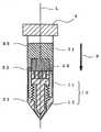
도 1 은 본 발명의 임플란트 재료의 제조 방법에서 사용하는, 다공질 세라믹 재료를 용기 내부의 임의의 깊이 위치에 설치하기 위한 다공질 세라믹 재료 위치결정 수단의 일실시형태의 개략도이다.
도 2 는 도 1 의 위치결정 수단을 사용하여 다공질 세라믹 재료를 용기 내부의 임의의 깊이 위치에 설치한 개략도이다.
도 3 은 본 발명의 임플란트 재료의 제조 방법에 있어서, 용기 내부에 다공질 세라믹 재료를 그 하부단이 버피 코트층에 접촉하도록 설치하고, 그 내부에 골수혈 및/또는 말초혈을 충전하고, 원심분리에 의해 버피 코트층을 형성시킨 상태의 개략도이다.
도 4 는 도 3 의 주요부 확대도이다.
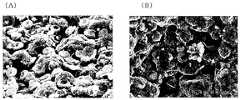
도 5 는 실시예에서 제조한 재료 단면의 SEM 관찰 이미지이다.
도 6 은 비교예 1 에서 제조한 재료 단면의 SEM 관찰 이미지이다.
도 7 은 비교예 2 에서 제조한 재료 단면의 SEM 관찰 이미지이다.1 is a schematic view of one embodiment of a porous ceramic material positioning means for installing a porous ceramic material at an arbitrary depth position inside a container for use in the method for producing an implant material of the present invention.
FIG. 2 is a schematic view of installing a porous ceramic material at an arbitrary depth position inside a container using the positioning means of FIG.
3 is a method of manufacturing an implant material of the present invention, in which a porous ceramic material is installed inside a container such that its lower end contacts the buffy coat layer, and therein, bone marrow and / or peripheral blood is filled therein, and centrifugation is performed. It is a schematic diagram of the state in which the buffy coat layer was formed.
4 is an enlarged view of a main part of FIG. 3.
5 is an SEM observation image of the material cross section prepared in the Example.
6 is an SEM observation image of a cross section of the material prepared in Comparative Example 1. FIG.
7 is an SEM observation image of a cross section of the material prepared in Comparative Example 2. FIG.
이하, 본 발명을 그 실시형태에 입각해서 설명한다.EMBODIMENT OF THE INVENTION Hereinafter, this invention is demonstrated based on the embodiment.
본 발명에 사용하는 다공질 세라믹 재료는, 바람직하게는 인산칼슘계 다공질 세라믹 재료이다.The porous ceramic material used in the present invention is preferably a calcium phosphate porous ceramic material.
인산칼슘계 세라믹의 예로서는, 하이드록시아파타이트, 불소아파타이트, 염소아파타이트, 인산삼칼슘, 메타인산칼슘, 인산사칼슘, 인산수소칼슘, 인산수소칼슘 2 수화물 등을 포함한다. 이들에서 선택되는 임의의 2 종 이상의 혼합물이 사용될 수 있다. 또한, 본 발명의 재료에 있어서, 인산칼슘의 Ca 성분의 일부가, Sr, Ba, Mg, Fe, Al, Y, La, Li, Na, K, Ag, Pd, Zn, Pb, Cd, H, 및 이 밖의 희토류 원소에서 선택되는 1 종 이상으로 치환될 수도 있다. 또한, (PO4) 성분의 일부가, VO4, BO3, SO4, CO3, SiO4등에서 선택되는 1 종 이상으로 치환될 수도 있다. 또한, (OH) 성분의 일부가, F, Cl, O, CO3, I, Br 에서 선택되는 1 종 이상으로 치환될 수도 있다.Examples of calcium phosphate-based ceramics include hydroxyapatite, fluorine apatite, chlorine apatite, tricalcium phosphate, calcium metaphosphate, tetracalcium phosphate, calcium hydrogen phosphate, calcium hydrogen phosphate dihydrate and the like. Any two or more kinds of mixtures selected from them can be used. In addition, in the material of the present invention, a part of Ca component of calcium phosphate is Sr, Ba, Mg, Fe, Al, Y, La, Li, Na, K, Ag, Pd, Zn, Pb, Cd, H, And other rare earth elements. In addition, a part of the (PO4 ) component is VO4 , BO3 , SO4 , CO3 , SiO4 It may be substituted with one or more selected from. Also, (OH) it is a part of the ingredient may be replaced by F, Cl, O, CO3, I, at least one element selected from Br.
골 형성에 있어서, 인산칼슘은, 하이드록시아파타이트, 불소아파타이트, 염소아파타이트 및 인산삼칼슘에서 선택되는 것이 바람직하고, 하이드록시아파타이트 및/또는 인산삼칼슘이 보다 바람직하다.In the bone formation, the calcium phosphate is preferably selected from hydroxyapatite, fluorine apatite, chlorine apatite and tricalcium phosphate, more preferably hydroxyapatite and / or tricalcium phosphate.
본 발명에 사용하는 다공질 세라믹 재료는 바람직하게는 40 ∼ 90 %, 보다 바람직하게는 50 ∼ 90 %, 더욱 바람직하게는 60 ∼ 90 % 의 기공률 (porocity) 을 가진다. 기공률이 40 % 이상이면, 많은 세포가 재료 안으로 침투되어 재료에 접착되어, 충분한 조직, 예를 들어 골 조직의 형성이 기대된다. 한편, 기공률이 90 % 이하이면, 이러한 재료는 통상적인 핸들링에 충분하고, 게다가 원심분리 조작시에 터지는 경우도 없다.The porous ceramic material used in the present invention preferably has a porosity of 40 to 90%, more preferably 50 to 90%, still more preferably 60 to 90%. If the porosity is 40% or more, many cells penetrate into the material and adhere to the material, so that formation of sufficient tissue, for example, bone tissue, is expected. On the other hand, if the porosity is 90% or less, such a material is sufficient for normal handling, and also does not burst at the time of centrifugal separation operation.
기공률은 JIS R 1634 에 준거하여 산출된다. 구체적으로는, 평가 대상인 다공질 세라믹 재료로부터 직경 6 ㎜×높이 8 ㎜ 의 원통형 시험편을 잘라낸다. 그 시험편의 중량 및 체적을 측정하여, 이하의 식으로부터 기공률을 산출한다.Porosity is computed based on JISR1634. Specifically, the cylindrical test piece of diameter 6mm x height 8mm is cut out from the porous ceramic material of evaluation object. The weight and volume of the test piece are measured, and the porosity is calculated from the following formula.
부피 밀도=(시험편의 무게)/(시험편의 체적)Bulk density = (weight of test piece) / (volume of test piece)
기공률=(1-부피 밀도/이론 밀도)×100Porosity = (1-volume density / theoretical density) × 100
본 발명에 사용하는 다공질 세라믹 재료는, 실질적으로 일방향으로 배열된 기공을 갖고 있다. "기공이 실질적으로 일방향으로 배열된다" 는 것은, 1 축 방향으로 연장된 다수의 기공이 존재하고, 그러한 기공 중, 예를 들어 절반 이상, 바람직하게는 80 % 이상의 기공이 30°이하의 각도로 장축 방향을 가지는 것을 말한다. 여기서 말하는 "각도" 란, 임의 평면상에서 각각의 기공의 장축의 정사영 (orthogonal projection) 에 의해 도시된 교차 각도를 말하는 것이다. 다공질 세라믹 재료는, 실질적으로 일방향으로 배열된 기공을 갖기 때문에, 혈액, 골수액 등의 세포 함유 액체가 기공을 통과하여 재료 내부를 통과하도록 하는 세포 함유 액체 투과성을 갖는다. 여기서 말하는 "세포 함유 액체가 기공을 통과한다" 란, 세포 함유 액체 중의 액체 성분 (조직액) 및 세포가 통과하는 것을 의미한다.The porous ceramic material used in the present invention has pores arranged substantially in one direction. "The pores are arranged substantially in one direction" means that there are a number of pores extending in one axial direction, of which, for example, at least half, preferably at least 80% of the pores are at an angle of 30 degrees or less. It has a long axis direction. The term "angle" as used herein refers to the crossing angle shown by orthogonal projection of the major axis of each pore on an arbitrary plane. Since the porous ceramic material has pores substantially arranged in one direction, it has cell-containing liquid permeability such that cell-containing liquids such as blood and bone marrow fluid pass through the pores and pass through the material. The term "cell-containing liquid passes through pores" means that the liquid component (tissue liquid) and cells in the cell-containing liquid pass.
세라믹 재료 중의 각각의 기공의 단면적 (즉, 기공의 장축과 직교하는 단면의 면적) 은, 바람직하게는 0.05×10⁻³ ∼ 100×10-3 ㎟ 이고, 보다 바람직하게는 0.05×10⁻³ ∼ 50×10-3 ㎟ 이다. 상기 범위 내의 크기이면, 혈액 및 골수액이 통과하는 데에 충분하고, 또한 혈액, 골수액 등의 조직액이 통과하기 쉬워지도록 모세관 현상을 유발한다. 하지만, 본 발명의 과제를 해결하기 위해, 재료 내의 모든 기공이 상기 단면적을 갖는 것이 반드시 필요한 것은 아니다.The cross-sectional area of each pore in the ceramic material (that is, the area of the cross section orthogonal to the major axis of the pores) is preferably 0.05 × 10⁻³ to 100 × 10−3
본 발명에 사용하는 다공질 세라믹 재료는, 공지된 방법에 의해 제조할 수 있다. 구체적인 예로서는, 세라믹 슬러리 내에 발포제에 의해 기공을 형성시키는 방법, 소성 (firing) 시에 탄화되는 물질을 혼합하고 또한 소결 과정에서 CO2등의 가스로서 상기 물질을 소실시킴으로써 기공을 형성하는 방법, 슬러리의 응고시 생긴 얼음의 승화 흔적을 기공으로서 사용하는 방법 등을 포함한다. 본 발명의 다공질 세라믹 재료로서 바람직한, 실질적으로 일방향으로 배열된 기공을 갖는 다공질 세라믹 재료는, 세라믹 슬러리를 일방향으로 동결시킴으로써, 일방향으로 성장한 서릿발상의 얼음을 형성시키고, 이 얼음을 승화, 소성함으로써 얻을 수 있다.The porous ceramic material used in the present invention can be produced by a known method. As a specific example, a method of forming pores by a blowing agent in a ceramic slurry, a material which is carbonized during firing is mixed and CO2 in the sintering process And a method of forming pores by dissipating the substance as a gas such as gas, a method of using the sublimation traces of ice generated during solidification of the slurry as pores, and the like. A porous ceramic material having pores arranged substantially in one direction, which is preferable as the porous ceramic material of the present invention, can be obtained by freezing the ceramic slurry in one direction, forming frost-shaped ice grown in one direction, and subliming and firing the ice. have.
도 1 은 다공질 세라믹 재료를 용기 내부의 임의의 깊이 위치에 설치하는 다공질 세라믹 재료 위치결정 수단 (이하, 간단히 "위치결정 수단" 이라고도 약칭한다) 의 일 실시형태의 개략도이고, 도 2 는 도 1 의 위치결정 수단을 사용하여 다공질 세라믹 재료를 용기 내부의 임의의 깊이 위치에 설치한 개략도이다.FIG. 1 is a schematic diagram of one embodiment of a porous ceramic material positioning means (hereinafter also simply referred to as “positioning means”) for installing a porous ceramic material at an arbitrary depth position inside a container, and FIG. 2 is a view of FIG. It is a schematic diagram in which a porous ceramic material is installed at an arbitrary depth position inside a container using a positioning means.
다공질 세라믹 재료 위치결정 수단 (10) 은, 스토퍼 (11) 와 어댑터 (12) 로 이루어지고, 고정된 스토퍼 (11) 가 어댑터 (12) 에 캡형으로 부착되는 구조로 되어 있다. 스토퍼 (11) 는 축 가장자리 방향의 그의 일방의 측부에 상면판 (top board) 을 갖는 튜브이고, 어댑터 (12) 는 스토퍼 (11) 와 연결해서 스토퍼 (11) 의 상면판 (1) 의 높이 위치를 조절하기 위한 부재이다. 스토퍼 (11) 의 상면판 (1) 의 표면이 다공질 세라믹 재료 (22) 의 배치면이 된다.The porous ceramic material positioning means 10 is composed of a
스토퍼 (11) 의 상면판 (1) 에는 세포가 통과할 수 있도록 하는 다수의 관통공 (2) 이 형성되어, 세포는 이 관통공 (2) 을 통과해서 하부 (즉, 어댑터 (12) 측) 로 자유롭게 이동할 수 있다. 이 관통공 (12) 의 단면 (즉, 관통공의 장축과 직교하는 단면) 의 크기는, 단지 세포가 통과하도록 하는 크기이면 된다. 또한, 관통공의 단면의 형상도 특별히 한정은 되지 않지만, 예를 들어, 관통공의 단면이 원형인 경우, 이 관통공의 기공 크기 (직경) 는 세포의 투과성의 관점에서 0.5 ㎜ 이상이 바람직하고, 1.5 ㎜ 이상이 보다 바람직하다. 이 기공 크기는, 상면판에 가해지는 원심력을 분산시켜 지지하기 위해서, 6 ㎜ 이하가 바람직하고, 4 ㎜ 이하가 보다 바람직하다. 게다가, 모든 관통공의 크기가 균일할 필요는 없으며, 상면판의 단면 (즉, 상면판의 두께 방향과 직교하는 단면) 에 있어서의 관통공의 비율 (면적률) 을 높일 목적으로, 큰 사이즈의 관통공들 사이의 간극에 작은 사이즈의 관통공을 배치해도 된다. 관통공이 원형 이외의 단면 형상인 경우, 관통공의 단면의 크기는 상기 범위 내의 직경으로 된 원형의 면적에 상당하는 크기로 하는 것이 바람직하다.The
스토퍼 (11) 의 상면판 (1) 의 단면에 있어서의 관통공 (2) 의 비율 (면적률) 이 지나치게 많으면 상면판의 강도가 약해지는 경향이 되고, 지나치게 적으면 세포의 통과를 방해하는 경향이 된다. 그리하여, 그 면적률 ([상면판의 단면에 존재하는 관통공의 총 단면적/상면판의 단면적]×100) 은 약 50 ∼ 95 % 가 바람직하고, 보다 바람직하게는 약 60 ∼ 90 % 이다. 상면판의 두께는, 특별히 한정은 되지 않지만, 지나치게 얇으면 상면판의 강도가 약해지는 경향이 되고, 지나치게 두꺼우면 위치결정을 위한 가동 범위가 작아지기 때문에 약 1 ∼ 7 ㎜ 가 바람직하다.When the ratio (area ratio) of the through
어댑터 (12) 는 스토퍼 (11) 의 상면판 (1) 을 용기 (21) 의 깊이 방향의 중간 위치에 배치시키고 또한 상면판 (11) 을 용기 (21) 의 깊이 방향에서 이동 가능하게 지지하기 위해 사용된다.The
스토퍼 (11) 와 어댑터 (12) 는, 스토퍼 (11) 의 상면판 (1) 의 어댑터 (12) 에 대한 높이 (즉, 상면판 (1) 과 어댑터 (12) 의 상부단 사이의 이간 거리) 를 변화시킬 수 있도록 연결되어 있다.The
스토퍼 (11) 의 상면판 (1) 의 어댑터 (12) 에 대한 높이를 변화시키기 위한 수단은, 특별히 한정되지 않고, 여러 가지 수단을 사용할 수 있지만, 조작 용이성, 구조의 간이성 (가공 용이성) 등의 관점에서 나사 기구가 바람직하다. 도 1 의 위치결정 수단 (10) 은, 이러한 나사 기구에 의해 연결되는 스토퍼 (11) 와 어댑터 (12) 로 구성되어 있으며, 스토퍼 (11) 의 내측 벽과, 어댑터 (12) 의 외측 벽이 함께 나사 결합되어 있다.The means for changing the height with respect to the
본 발명에 있어서의 다공질 세라믹 재료 위치결정 수단 (10) (스토퍼 (11) 및 어댑터 (12)) 은 내멸균성을 갖고, 또한 원심력에 견디는 강도를 갖는 것이 중요하다. 예를 들어, 스테인리스강 등의 금속이나 PEEK (폴리에테르에테르케톤) 등의 수지로 형성되어 있는 것이 바람직하다.It is important that the porous ceramic material positioning means 10 (the
본 발명에서는, 임플란트 재료를 제조할 때, 먼저, 다공질 세라믹 재료를 용기 내부의 임의의 깊이 위치에 설치한다 (단계 A). 즉, 그 단계 (A) 에서는, 용기 (21) 의 내부에 다공질 세라믹 재료 위치결정 수단 (10) (스토퍼 (11) 및 어댑터 (12)) 을 삽입하고, 스토퍼 (11) 의 상면판 (1) 에 다공질 세라믹 재료 (22) 를 배치한다. 스토퍼 (11) 의 상면판 (1) 의 어댑터 (12) 에 대한 높이를 미리 원하는 높이로 설정해 둠으로써, 다공질 세라믹 재료 (22) 는, 용기 (21) 내부의 임의의 깊이 위치에 설치될 수 있다 (도 2).In the present invention, when manufacturing the implant material, first, the porous ceramic material is installed at an arbitrary depth position inside the container (step A). That is, in the step (A), the porous ceramic material positioning means 10 (
용기 (21) 에는, 후술하는 바와 같이, 골수혈, 말초혈 등의 세포 함유 액체가 충전되기 때문에, 세포 함유 액체 중의 세포의 분포 상태를 육안으로 관찰할 수 있도록 투명한 재료로 용기를 형성하는 것이 중요하다. 예를 들어, 폴리프로필렌, 폴리스티렌, 아크릴 수지 등의 수지, 유리 등으로 형성되어 있는 것이 바람직하다.Since the
용기 (21) 의 형상은, 특별히 한정되는 것은 아니지만, 후술하는 바와 같이, 용기 (21) 에는 원심기로 원심력을 작용시킨다. 이 때문에, 원심기에 대한 장착이 용이하도록, 원통형의 용기가 바람직하게 사용된다. 또, 상기 서술한 바와 같이, 용기 (21) 의 내부에는, 스토퍼 (11) 의 상면판 (1) 의 어댑터 (12) 에 대한 높이가 변화하는 다공질 세라믹 재료 위치결정 수단 (10) 이 삽입되기 때문에, 용기 (21) 의 적어도 스토퍼 (11) 의 가동 범위에 대응하는 부분은, 단면의 형상 및 크기가 동일한 것이 바람직하다.Although the shape of the
본 발명에 사용하는 세포 함유 액체는, 기본적으로는, 골수혈 및/또는 말초혈을 포함한다. 사용된 골수혈 및 말초혈은, 인간 또는 동물 (특히, 포유 동물) 유래 골수혈 및 말초혈이다.The cell-containing liquid used in the present invention basically includes bone marrow blood and / or peripheral blood. Bone and peripheral blood used are bone marrow and peripheral blood derived from humans or animals (especially mammals).
게다가, 세포 함유 액체는, 말초혈 및/또는 골수혈 및 새로 다른 세포나 다른 세포 함유 액체의 혼합물일 수 있다. 새로 첨가하는 세포 소스의 예로는, 제대혈;골수혈, 말초혈, 지방, 제대혈, 배 (embryo), 해면골 및 골막 등으로부터 채취한 간세포;그리고 분화된 간세포 등을 포함할 수 있다. 또, 세포 함유 액체에는 피브린의 응고를 방지하기 위해 헤파린, 시트르산 등의 항응고제를 첨가할 수도 있다.In addition, the cell containing liquid may be a mixture of peripheral blood and / or bone marrow and freshly other cells or other cell containing liquid. Examples of the newly added cell source may include umbilical cord blood; hepatocytes obtained from bone marrow blood, peripheral blood, fat, umbilical cord blood, embryos, sponges, periosteum, etc .; and differentiated hepatocytes. In addition, anticoagulants such as heparin and citric acid may be added to the cell-containing liquid in order to prevent coagulation of fibrin.
또한, 전술한 바와 같이, 본 발명에서 사용하는 다공질 세라믹 재료 (22) 는, 실질적으로 일방향으로 배열된 기공을 갖고 있다. 그리고, 도 2 에 나타내는 바와 같이, 다공질 세라믹 재료 (22) 를 실질적으로 일방향으로 배열된 기공 (22a) 의 장축이 용기 (21) 의 축선 (L) 을 따르도록 배치되어, 후술하는 단계 (C) 에서 용기 (21) 내에 충전된 세포 함유 액체에서의 세포가 원심력의 작용에 의해 기공을 통과한다. 또한, "실질적으로 일방향으로 배열된 기공 (22a) 의 장축이 용기의 축선 (L) 을 따른다" 란, 실질적으로 일방향으로 배열된 기공 중의 절반 이상 (바람직하게는 60 % 이상, 보다 바람직하게는 70 % 이상) 의 주축과 용기의 축선의 교차 각도 (기공의 주축과 용기의 축선의 임의 평면에 대한 정사영의 교차 각도) 가 30°이내에 있는 것으로, 상기 교차 각도는 작으면 작을수록 바람직하다.In addition, as described above, the porous
단계 (B) 에서는, 단계 (A) 에서 얻어진 용기 (21) 에 세포 함유 액체를 충전하고, 상기 용기 내부의 임의의 깊이 위치에 다공질 세라믹 재료 (22) 가 설치된다. 용기 (21) 의 삽입구 (입구) 에는, 예를 들어, 폴리에틸렌 등으로 이루어지는 착탈 가능한 캡 (4) 이 장착되어 있어, 단계 (A) 에서 단계 (B) 로 이행하는 동안 및/또는 단계 (B) 에서 이하에 기재하는 단계 (C) 로 이행하는 동안 등에 있어서, 용기 내에 먼지 등의 이물질이 침입하지 않도록 용기 (21) 를 밀폐시킨다.In step (B), the
단계 (C) 에서는, 단계 (B) 에서 얻어진, 세포 함유 액체가 충전되고 또한 캡 (4) 에 의해 밀폐된 용기 (21) 에 원심력을 작용시킨다. 원심력은 일반적인 원심 분리기 (원심력 작용 수단) 를 사용해서 작용시키고, 원심 분리기의 회전부를 회전시켜, 용기 (21) 에 그 깊이 방향으로 향하는 원심력 (즉, 용기 (21) 의 축선 (L) 을 따르는 방향의 원심력 (도 3 중의 화살표 F)) 을 작용시킨다. 이 경우의 원심력은, 바람직하게는 100×g ∼ 2000×g 이고, 보다 바람직하게는 100×g ∼ 1500×g 이다.In step (C), centrifugal force is exerted on the
골수혈, 말초혈 등의 세포 함유 액체를, 상기 범위 내의 원심력으로 원심분리함으로써, 세포 함유 액체는 원심 분리되어 버피 코트층을 생성한다. 버피 코트층에는 골 및 연골로 분화되는 능력을 갖는 간세포 등의 유핵 세포, 혈소판, 조직 수복에 유용한 사이토카인 등의 농축물이 함유되는 것이 알려져 있다. 한편, 적혈구는 골 및 연골의 조직 수복에는 거의 관여하지 않는다.By centrifuging a cell-containing liquid such as bone marrow blood or peripheral blood with a centrifugal force within the above range, the cell-containing liquid is centrifuged to form a buffy coat layer. It is known that the buffy coat layer contains concentrates such as nucleated cells such as hepatocytes having the ability to differentiate into bone and cartilage, platelets, and cytokines useful for tissue repair. Red blood cells, on the other hand, are rarely involved in tissue repair of bone and cartilage.
도 3 은 말초혈, 골수 등의 세포 함유 액체를 충전하여, 상기 범위 내의 원심력으로 용기 (21) 를 원심분리한 후의 용기 (21) 의 내부의 바람직한 상태를 개략적으로 나타내고 있다. 세포 함유 액체는 원심분리되어, 용기 (21) 의 바닥부에서부터 상부에 걸쳐 적혈구층 (31), 버피 코트층 (32) 및 혈청층 (33) 이 형성되어 있다. 또한, 혈청층 (33) 은 버피 코트층 (32) 과 같이 고농도로 유핵 세포 및 사이토카인을 함유하고 있지 않지만, 세포의 접착, 증식 및 분화에 유용한 단백질, 사이토카인 등이 함유된다.Fig. 3 schematically shows a preferable state inside the
원심분리 시간은 용기 (21) 의 크기, 사용하는 세포 함유 액체 등에 따라서 상이하지만, 일반적으로는 1 ∼ 20 분이고, 바람직하게는 5 ∼ 15 분이다. 원심분리 시간이 1 분보다 짧으면 세포와 조직액이 충분히 분리되지 않는 경향이 되고, 20 분보다 길면 세포에 주는 손상이 커지는 경향이 된다. 또, 원심분리시의 용기 내의 세포 함유 액체의 온도는, 바람직하게는 3 ∼ 6 ℃ 이다.The centrifugation time varies depending on the size of the
또한, 용기 (21) 내의 다공질 세라믹 재료 (22) 및 위치결정 수단 (10) (스토퍼 (11) 의 상면판 (1)) 둘 다는, 세포 함유 액체 중의 세포가 통과할 수 있는 기공 (기공 (22a), 관통공 (2)) 을 갖고 있기 때문에, 세포 함유 액체로 충전된 용기 (21) 에 원심력을 작용시키면, 다공질 세라믹 재료 (22) 및 위치결정 수단 (10) 이 존재하지 않는 상태 (세포 함유 액체만이 용기 (21) 내에 충전된 상태) 에서 용기에 원심력을 작용시켰을 때와 마찬가지로 세포 함유 액체는 원심분리되어, 버피 코트층을 생성한다.In addition, both the porous
도 4 는 도 3 의 주요부의 확대도이다. 단계 (A) 에서의, 다공질 세라믹 재료 (22) 의 용기 (21) 내에서의 깊이 위치 (용기의 깊이 방향의 위치) 를, 다공질 세라믹 재료 (22) 의 적어도 일부가, 단계 (C) 에서 생성되는 버피 코트층 (32) 과 접촉하도록 (겹치도록) 설정해 둠으로써, 도 4 에 나타내는 바와 같이, 버피 코트층 (32) 은 다공질 세라믹 재료 (22) 의 기공 (22a) 에 침입하여 내포되어, 버피 코트 성분이 다공질 세라믹 재료 (22) 의 기공 (22a) 내표면에 부착된다. 버피 코트 성분은 유핵 세포, 사이토카인 등의 농축물을 함유하고, 이는 골 조직이나 연골 조직의 재생에 매우 효과적으로 작용한다. 여기서, 버피 코트 성분은 다공질 세라믹 재료 (22) 의 기공 (22a) 내표면에 부착되어 있기 때문에, 생체 내에 이식할 때까지 임플란트 재료로부터 잘 탈락되지 않는다. 도 4 는 다공질 세라믹 재료 (22) 의 용기 내에서의 설치 위치의 바람직한 양태를 나타내고 있으며, 다공질 세라믹 재료 (22) 의 하부단부가 버피 코트층 (32) 과 접촉하고 (겹치고), 다공질 세라믹 재료 (22) 의 나머지 부분은 혈청층과 접촉하고 있어 (겹치고 있어), 골 조직이나 연골 조직의 재생에 작용하는 혈청층의 성분도 다공질 세라믹 재료 (22) 에 부착시키고 있다. 버피 코트층 (32) 의 두께와 동등한 두께를 가진 다공질 세라믹 재료 (22) 를 사용하면, 그 내부에 부착되고 또한 버피 코트 성분 유래의 유핵 세포의 농축물, 사이토카인 등만을 함유하는 다공질 세라믹 재료를 얻는 것이 가능하다. 전술한 다공질 세라믹 재료 (22) 의 하단부는 다공질 세라믹 재료 (22) 에 있어서의 위치결정 수단 (10) 에 접촉하는 쪽의 단부를 말하는 것이다.4 is an enlarged view of a main part of FIG. 3. In step (A), at least a part of the porous
단계 (C) 에서 형성되는 버피 코트층 (32) 의 위치는 골수혈, 말초혈 등의 세포 함유 액체를 채취하는 개체에 따라서도 상이하지만, 미리 다공질 세라믹 재료 (22) 만을 제거한 상태 (즉, 용기 내 (21) 내에 위치결정 수단 (10) 을 삽입하여, 세포 함유 액체로 용기를 충전한 상태) 에서 원심력을 작용시킴으로써 분명히 할 수 있다.Although the position of the buffy coat layer 32 formed in step (C) is different depending on the individual collecting the cell-containing liquid such as bone marrow, peripheral blood, etc., the state in which only the porous
이상의 단계를 거침으로써, 다공질 세라믹 재료 (22) 에 세포 함유 액체 중의 유용한 세포가 농축되어 심어진 임플란트 재료가 제조된다.By going through the above steps, an implant material in which useful cells in the cell-containing liquid are concentrated and planted in the porous
이와 같이 하여 얻어진, 본 발명의 임플란트 재료는, 골 이식재, 골연골 이식재, 재생 의료 재료 등으로서 유용하다.The implant material of the present invention thus obtained is useful as a bone graft material, osteochondral graft material, regenerative medical material or the like.
또한, 보다 효율적으로 골 조직 및 연골 조직을 재생하는 것을 목적으로 하여, 본 발명의 임플란트 재료는 심어진 세포를 배양하는 조작 이후에 사용해도 된다. 또한, 형질전환 증식 인자 (TGF-β), 골 형성 단백질 (BMP) 등의 조직, 예를 들어 골 조직 및 연골 조직에 대해 성장을 촉진시키는 작용이 있는 물질을, 본 발명의 임플란트 재료에 함침, 흡착, 고정화시켜도 된다.In addition, for the purpose of more efficiently regenerating bone tissue and cartilage tissue, the implant material of the present invention may be used after the operation of culturing the planted cells. In addition, the implant material of the present invention is impregnated with a substance having a function of promoting growth in tissues such as transforming growth factor (TGF-β), bone morphogenic protein (BMP), for example, bone tissue and cartilage tissue, You may adsorb | suck and fix | immobilize.
세포 함유 액체 및 다공질 세라믹 재료를 수용할 수 있는 전술한 용기 (21) 와, 다공질 세라믹 재료 위치결정 수단 (10) 은, 본 발명의 임플란트 재료 제조용 기구를 구성한다. 또한, 이러한 임플란트 재료 제조용 기구와 함께, 상기 서술한 다공질 세라믹 재료 (22) 를 구비함으로써, 본 발명의 임플란트 재료 제조용 키트가 구성된다.The
실시예Example
이하, 실시예를 참조하여 본 발명을 보다 구체적으로 설명하지만, 본 발명은 이하에 기재된 실시예에 의해 한정되는 것은 아니다.Hereinafter, the present invention will be described in more detail with reference to Examples, but the present invention is not limited to the Examples described below.
[버피 코트 위치의 확인][Confirmation of buffy coat position]
(원통형) 폴리프로필렌제 원심분리 튜브 (내경 14 ㎜, 용량 15 ㎖ 의 Greiner GmbH (독일) 제조) 의 용기 (21) 중에, 튜브의 외경이 13 ㎜ 인 PEEK 제의 스토퍼 (11) (상면판의 두께:5 ㎜, 관통공:직경 2 ㎜ 의 원형 관통공, 관통공의 면적률:60 %) 및 그 스토퍼와 나사 기구에 의해 접속되는 원통형 어댑터 (12) (내경 7 ㎜) 를 설치하였다. 용기의 8 ㎖ 눈금까지 토끼 심장혈을 충전하여, 4 ℃ 에서 1500×g 로 10 분간 원심분리하였다. 원심분리 후에 용기를 꺼내, 육안으로 버피 코트층의 위치를 확인하고, 그 위치는 용기의 5.0 ㎖ ∼ 5.1 ㎖ 눈금에 있었다.In a
[실시예 1]Example 1
상기 버피 코트 위치의 전술한 확인 실험에 사용한 용기 (21), 스토퍼 (11) 및 어댑터 (12) 와 동일한 용기, 스토퍼, 및 어댑터를 사용하여, 스토퍼 (11) 의 상면판의 상면의 위치가 스토퍼 (11) 와 어댑터 (12) 의 나사 기구에 의해 용기 (21) 의 5 ㎖ 눈금 위치에 있도록 조정되었다. 다음으로, 스토퍼 (11) 의 상면판 상에, 하이드록시아파타이트로 이루어지는 다공질 세라믹 재료 (기공률 75 %, 기공의 평균 단면적 18.6×10⁻³ ㎟, 직경:11 ㎜, 높이 10 ㎜ 의 원통형, 일방향 (재료의 높이 방향) 으로 배열된 기공을 함유) 를 기공의 배열 방향이 상면판과 수직이 되도록 배치하였다. 용기 (21) 는 이 용기 (21) 의 8 ㎖ 눈금까지 토끼 심장혈로 충전되었다. 이 때, 혈액은 모세관 작용에 의해 다공질 세라믹 재료의 내부까지 급속히 침투하였다. 그 후, 혈액을 4 ℃ 에서 1500×g 로 10 분간 원심분리하였다.Using the same container, stopper, and adapter as the
[비교예 1]Comparative Example 1
실시예 1 에서 사용한 용기 (21) 와 동일한 용기, 스토퍼 (11) 및 어댑터 (12) 를 사용하지 않고, 실시예 1 에서 사용한 다공질 세라믹 재료와 동일한 다공질 세라믹 재료를 사용하여, 용기 (21) 내부의 바닥부에 다공질 세라믹 재료를 설치하고, 그 용기 (21) 에 토끼 심장혈을 8 ㎖ 눈금까지 충전하고, 이 용기는 10 분간 정치하여 다공질 세라믹 재료 내부로 토끼 심장혈을 침투시켰다.Without using the same container,
[비교예 2]Comparative Example 2
실시예 1 에서 사용한 용기 (21), 스토퍼 (11) 및 어댑터 (12) 와 동일한 용기, 스토퍼 및 어댑터를 사용하여, 스토퍼 (11) 의 상면판의 상면의 위치가 스토퍼 (11) 와 어댑터 (12) 의 나사 기구에 의해 용기 (11) 의 5 ㎖ 눈금 위치가 되도록 조정되었다. 다음으로, 스토퍼 (11) 의 상면판 상에, 하이드록시아파타이트로 이루어지는 다공질 세라믹 재료 (기공률 55 %, 기공의 평균 단면적 43.2×10⁻³ ㎟, 직경:11 ㎜, 높이 10 ㎜ 의 원통형, 3 차원 그물상 기공 구조 (기공들이 연통되어 있지 않음) 를 가짐) 를 배치하였다. 용기 (21) 는 용기 (11) 의 8 ㎖ 눈금까지 토끼 심장혈을 충전하였다. 이 때, 모세관 작용에 의한 다공질 세라믹 재료의 내부로의 혈액의 침투는 관찰되지 않았다. 그 후, 혈액은 4 ℃ 에서 1500×g 로 10 분간 원심분리되었다.Using the same container, stopper and adapter as the
도 5 는 실시예 1 에서 조제한 재료 단면의 SEM 관찰 이미지를 도시한다. 도 5 의 (A) 는 상부의 관찰 이미지이고, 도 5 의 (B) 는 하부의 관찰 이미지이다. 상부를 나타내는 도 5 의 (A) 에서는 거의 세포를 포함하지 않는데에 반해, 하부를 나타내는 도 5 의 (B) 에서는, 유핵 세포의 존재를 확인할 수 있다. 도 5 의 (A) 및 도 5 의 (B) 둘 다에서, 조직 재생에 불필요한 적혈구의 수는 적다.5 shows an SEM observation image of the material cross section prepared in Example 1. FIG. FIG. 5A is an upper observation image, and FIG. 5B is an lower observation image. In FIG. 5A showing the upper part, almost no cells are included, while in FIG. 5B showing the lower part, the presence of nucleated cells can be confirmed. In both FIG. 5A and FIG. 5B, the number of red blood cells unnecessary for tissue regeneration is small.
도 6 은 비교예 1 에서 조제한 재료 단면의 SEM 관찰 이미지이다. 도 6 의 (A) 는 상부의 관찰 이미지이고, 도 6 의 (B) 는 하부의 관찰 이미지이다. 상부를 나타내는 도 6 의 (A) 및 하부를 나타내는 도 6 의 (B) 에 있어서, 다수의 세포를 확인할 수 있지만, 이 세포의 대부분은 조직 재생에 불필요한 적혈구이다.6 is an SEM observation image of a material cross section prepared in Comparative Example 1. FIG. 6A is an observation image of the upper portion, and FIG. 6B is an observation image of the lower portion. In FIG. 6 (A) showing the upper part and FIG. 6 (B) showing the lower part, many cells can be identified, but most of these cells are red blood cells which are unnecessary for tissue regeneration.
실시예 1 과 비교예 1 의 대비로부터, 본 발명의 방법은 적혈구를 제거하고, 조직 수복에 유용한 세포를 농축시키며, 다공질 세라믹에 이러한 세포를 부착시킴을 알 수 있다.From the contrast of Example 1 and Comparative Example 1, it can be seen that the method of the present invention removes red blood cells, concentrates the cells useful for tissue repair, and attaches these cells to the porous ceramic.
도 7 은 비교예 2 에서 조제한 재료 단면의 SEM 관찰 이미지이다. 도 7 의 (A) 는 상부의 관찰 이미지이고, 도 7 의 (B) 는 하부의 관찰 이미지이다. 상부 및 하부 둘 다는, 원심분리 조작에 의해 내부에 진입하는 조직 재생에 불필요한 적혈구를 주로 포함하지만, 그 수는 하부를 나타내는 도 8 의 (B) 보다 상부를 나타내는 도 8 의 (A) 에서 더 많다.7 is an SEM observation image of a cross section of a material prepared in Comparative Example 2. FIG. 7A is an observation image of the upper portion, and FIG. 7B is an observation image of the lower portion. Both the top and bottom mainly contain red blood cells that are unnecessary for regeneration of tissue entering the interior by centrifugation, but the number is greater in FIG. 8 (A) showing the top than in FIG. 8 (B) indicating the bottom. .
산업상 이용가능성Industrial availability
본 발명은, 정형 외과 분야에서, 특히 골 결손 또는 연골 결손의 재생시, 약물 등의 첨가물을 사용하지 않고, 골 조직 및 연골 조직의 높은 수복 효과와 조제의 간편성을 동시에 달성하는 임플란트 재료의 제조 방법을 제공하는 것이다.The present invention, in the field of orthopedic surgery, in particular in the regeneration of bone defects or cartilage defects, without the use of additives such as drugs, achieving a high repair effect of bone tissue and cartilage tissue and the simplicity of preparation at the same time To provide.
본 출원은 일본에서 출원된 일본 특허출원 제 2010-262538 호를 기초로 하고 있으며, 그 내용은 본 명세서에 모두 포함된다.This application is based on Japanese Patent Application No. 2010-262538 for which it applied in Japan, The content is altogether included in this specification.
1 : 상면판
2 : 관통공
10 : 다공질 세라믹 재료 위치결정 수단
11 : 스토퍼
12 : 어댑터
12a : 어댑터의 상부단
21 : 용기
22 : 다공질 세라믹 재료
22a : 기공
31 : 적혈구층
32 : 버피 코트층
33 : 혈청층1: top plate
2: through hole
10: porous ceramic material positioning means
11: stopper
12: adapter
12a: upper end of the adapter
21: container
22: porous ceramic material
22a: pore
31: red blood cell layer
32: buffy coat layer
33: serum layer
Claims (9)
Translated fromKorean단계 (B): 적어도 골수혈 및/또는 말초혈을 함유하는 세포 함유 액체로 상기 용기를 충전하는 단계, 및
단계 (C):상기 용기에 상기 용기의 축선을 따르는 방향으로 원심력을 작용시키는 단계를 포함하는, 임플란트 재료의 제조 방법.Step (A): installing a porous ceramic material having pores arranged substantially in one direction at an arbitrary depth position inside the container,
Step (B): filling the container with a cell containing liquid containing at least bone marrow and / or peripheral blood, and
Step (C): The method of manufacturing an implant material, comprising applying a centrifugal force to the vessel in a direction along the axis of the vessel.
상기 단계 (A) 에서, 상기 다공질 세라믹 재료는 실질적으로 일방향으로 배열된 상기 기공들의 장축이 상기 용기의 축선을 따르도록 설치되는, 임플란트 재료의 제조 방법.The method of claim 1,
In the step (A), the porous ceramic material is installed so that the long axis of the pores arranged in one direction is substantially along the axis of the container.
상기 원심력은 상기 단계 (C) 에서 100×g ∼ 2000×g 로 제어되는, 임플란트 재료의 제조 방법.3. The method according to claim 1 or 2,
The centrifugal force is controlled to 100 x g to 2000 x g in the step (C).
상기 세포 함유 액체는 상기 단계 (C) 에서 원심 분리되어 버피 코트층을 형성하는, 임플란트 재료의 제조 방법.3. The method according to claim 1 or 2,
The cell-containing liquid is centrifuged in step (C) to form a buffy coat layer.
상기 단계 (A) 에서, 상기 다공질 세라믹 재료는 적어도 상기 다공질 세라믹 재료의 일부가 상기 단계 (C) 에서 생성되는 버피 코트층과 접촉하도록 설치되는, 임플란트 재료의 제조 방법.5. The method of claim 4,
In the step (A), the porous ceramic material is installed so that at least a portion of the porous ceramic material is in contact with the buffy coat layer produced in the step (C).
상기 세포 함유 액체 중의 세포들이 통과할 수 있는 관통공을 갖고, 상기 용기 내부의 임의의 깊이 위치에 상기 다공질 세라믹 재료를 설치하기 위한, 다공질 세라믹 재료 위치결정 수단을 포함하는, 임플란트 재료 제조용 기구.A container capable of containing cell-containing liquid and porous ceramic material containing at least bone and / or peripheral blood;
And a porous ceramic material positioning means having a through hole through which cells in the cell-containing liquid can pass and for installing the porous ceramic material at an arbitrary depth position inside the container.
적어도 골수혈 및/또는 말초혈을 함유하는 세포 함유 액체 및 상기 다공질 세라믹 재료를 수용할 수 있는 용기, 및
상기 세포 함유 액체 중의 세포들이 통과할 수 있는 관통공을 갖고, 상기 용기 내부의 임의의 깊이 위치에 상기 다공질 세라믹 재료를 설치하기 위한, 다공질 세라믹 재료 위치결정 수단을 포함하는, 임플란트 재료 제조용 키트.Porous ceramic materials,
A container capable of containing a cell-containing liquid and at least a porous ceramic material containing at least bone and / or peripheral blood, and
And a porous ceramic material positioning means having a through hole through which cells in the cell-containing liquid can pass and for installing the porous ceramic material at an arbitrary depth position inside the container.
상기 다공질 세라믹 재료는 실질적으로 일방향으로 배열된 기공을 갖는 다공질 세라믹 재료인, 임플란트 재료 제조용 키트.The method of claim 8,
And the porous ceramic material is a porous ceramic material having pores arranged substantially in one direction.
Applications Claiming Priority (3)
| Application Number | Priority Date | Filing Date | Title |
|---|---|---|---|
| JP2010262538 | 2010-11-25 | ||
| JPJP-P-2010-262538 | 2010-11-25 | ||
| PCT/JP2011/075973WO2012070400A1 (en) | 2010-11-25 | 2011-11-10 | Method for producing implant material |
Related Child Applications (1)
| Application Number | Title | Priority Date | Filing Date |
|---|---|---|---|
| KR1020167004410ADivisionKR101667515B1 (en) | 2010-11-25 | 2011-11-10 | Method for producing implant material |
Publications (1)
| Publication Number | Publication Date |
|---|---|
| KR20130102101Atrue KR20130102101A (en) | 2013-09-16 |
Family
ID=46145748
Family Applications (2)
| Application Number | Title | Priority Date | Filing Date |
|---|---|---|---|
| KR1020137016268ACeasedKR20130102101A (en) | 2010-11-25 | 2011-11-10 | Method for producing implant material |
| KR1020167004410AExpired - Fee RelatedKR101667515B1 (en) | 2010-11-25 | 2011-11-10 | Method for producing implant material |
Family Applications After (1)
| Application Number | Title | Priority Date | Filing Date |
|---|---|---|---|
| KR1020167004410AExpired - Fee RelatedKR101667515B1 (en) | 2010-11-25 | 2011-11-10 | Method for producing implant material |
Country Status (7)
| Country | Link |
|---|---|
| US (1) | US9782518B2 (en) |
| EP (1) | EP2644208B1 (en) |
| JP (1) | JP5924693B2 (en) |
| KR (2) | KR20130102101A (en) |
| CN (1) | CN103384535B (en) |
| CA (1) | CA2818657C (en) |
| WO (1) | WO2012070400A1 (en) |
Families Citing this family (6)
| Publication number | Priority date | Publication date | Assignee | Title |
|---|---|---|---|---|
| CN103690998B (en)* | 2013-12-10 | 2015-12-09 | 北京大学口腔医学院 | A bone graft material embedded with bone material gel in PRF |
| CN103690999B (en)* | 2013-12-10 | 2015-08-05 | 北京大学口腔医学院 | The liquid-solid embedded material turning to gel film of a kind of PRF precursor |
| KR102660683B1 (en)* | 2015-11-03 | 2024-04-26 | 헬스 코포레이션 오브 갤리리 메디컬 센터 | Device and method for processing artificial bone implants with blood |
| JP7455302B2 (en)* | 2019-07-18 | 2024-03-26 | Orbray株式会社 | Dental implant body and method for manufacturing dental implant body |
| CN114432499B (en)* | 2021-12-20 | 2023-02-17 | 浙江脉通智造科技(集团)有限公司 | Artificial blood vessel and preparation method thereof |
| US20250257468A1 (en)* | 2024-02-12 | 2025-08-14 | U.S. Army DEVCOM, Army Research Laboratory | Methods for infiltrating gallium into porous scaffolds |
Family Cites Families (13)
| Publication number | Priority date | Publication date | Assignee | Title |
|---|---|---|---|---|
| US6200606B1 (en) | 1996-01-16 | 2001-03-13 | Depuy Orthopaedics, Inc. | Isolation of precursor cells from hematopoietic and nonhematopoietic tissues and their use in vivo bone and cartilage regeneration |
| US5824084A (en)* | 1996-07-03 | 1998-10-20 | The Cleveland Clinic Foundation | Method of preparing a composite bone graft |
| JP5007476B2 (en) | 2001-03-23 | 2012-08-22 | オリンパス株式会社 | Artificial aggregate |
| JP4217421B2 (en) | 2002-04-30 | 2009-02-04 | オリンパス株式会社 | Container for production of biological tissue filling material |
| US20060278588A1 (en)* | 2002-05-24 | 2006-12-14 | Woodell-May Jennifer E | Apparatus and method for separating and concentrating fluids containing multiple components |
| CN1565644A (en)* | 2003-06-27 | 2005-01-19 | 中国人民解放军军事医学科学院基础医学研究所 | Manufacturing method of tissue engineered bone |
| CN101072572B (en) | 2003-07-09 | 2013-12-11 | 华沙整形外科股份有限公司 | Isolation of bone marrow fraction rich in connective tissue growth components and the use thereof to promote connective tissue formation |
| JP2005040060A (en)* | 2003-07-23 | 2005-02-17 | National Institute Of Advanced Industrial & Technology | Highly efficient seeding of cells on porous biocompatible materials |
| JP2005137478A (en) | 2003-11-05 | 2005-06-02 | Olympus Corp | Manufacturing method of bone prosthesis |
| JP2006025635A (en) | 2004-07-13 | 2006-02-02 | Kaneka Corp | Method, instrument or apparatus for disposing cells in porous support |
| EP2039668B1 (en)* | 2006-06-23 | 2019-08-21 | Kuraray Co., Ltd. | Method of producing a porous ceramic material |
| WO2008111432A1 (en) | 2007-03-12 | 2008-09-18 | Kuraray Co., Ltd. | Method for production of porous ceramic material |
| JP5045943B2 (en) | 2008-07-09 | 2012-10-10 | 国立大学法人京都大学 | Method for producing porous ceramic material |
- 2011
- 2011-11-10KRKR1020137016268Apatent/KR20130102101A/ennot_activeCeased
- 2011-11-10WOPCT/JP2011/075973patent/WO2012070400A1/ennot_activeCeased
- 2011-11-10JPJP2012545681Apatent/JP5924693B2/ennot_activeExpired - Fee Related
- 2011-11-10EPEP11843553.6Apatent/EP2644208B1/ennot_activeNot-in-force
- 2011-11-10CACA2818657Apatent/CA2818657C/ennot_activeExpired - Fee Related
- 2011-11-10CNCN201180056884.7Apatent/CN103384535B/ennot_activeExpired - Fee Related
- 2011-11-10USUS13/989,606patent/US9782518B2/ennot_activeExpired - Fee Related
- 2011-11-10KRKR1020167004410Apatent/KR101667515B1/ennot_activeExpired - Fee Related
Also Published As
| Publication number | Publication date |
|---|---|
| EP2644208B1 (en) | 2016-06-29 |
| US9782518B2 (en) | 2017-10-10 |
| CN103384535A (en) | 2013-11-06 |
| JPWO2012070400A1 (en) | 2014-05-19 |
| WO2012070400A1 (en) | 2012-05-31 |
| CA2818657A1 (en) | 2012-05-31 |
| EP2644208A4 (en) | 2014-09-24 |
| EP2644208A1 (en) | 2013-10-02 |
| CN103384535B (en) | 2015-02-11 |
| US20130253657A1 (en) | 2013-09-26 |
| KR101667515B1 (en) | 2016-10-18 |
| CA2818657C (en) | 2016-01-05 |
| JP5924693B2 (en) | 2016-05-25 |
| KR20160025041A (en) | 2016-03-07 |
Similar Documents
| Publication | Publication Date | Title |
|---|---|---|
| KR20130102101A (en) | Method for producing implant material | |
| EP3294306B1 (en) | Bone fragment and tissue processing system | |
| EP1464307B1 (en) | Intervertebral fusion implant | |
| JP4481566B2 (en) | Composite bone marrow transplant, preparation method and kit | |
| KR101212433B1 (en) | Method for production of porous ceramic material | |
| JP5583333B2 (en) | Kit used to make a part of a joint prosthesis for use in arthroplasty | |
| JP2014000461A (en) | Bone substitute material | |
| CN108025113B (en) | Method for preparing osteogenic bone graft | |
| US20250169926A1 (en) | Device and method for treatment of an artificial bone implant with blood | |
| EP2974753A1 (en) | Bone regenerating biomaterials with selected cells from peripheral blood | |
| KR100853635B1 (en) | Porous synthetic bone graft and its manufacturing method | |
| Qian | Development of Multifunctional Beta-Tricalcium Phosphate Scaffolds for Angiogenesis and Osteogenesis | |
| JP2004187846A (en) | Biological components | |
| JP6959031B2 (en) | A gelling method for gelling platelet-rich plasma, and a kit used for the gelling method. | |
| HK1052141B (en) | Bone-regeneration material |
Legal Events
| Date | Code | Title | Description |
|---|---|---|---|
| A201 | Request for examination | ||
| AMND | Amendment | ||
| P11-X000 | Amendment of application requested | St.27 status event code:A-2-2-P10-P11-nap-X000 | |
| P13-X000 | Application amended | St.27 status event code:A-2-2-P10-P13-nap-X000 | |
| PA0105 | International application | St.27 status event code:A-0-1-A10-A15-nap-PA0105 | |
| PA0201 | Request for examination | St.27 status event code:A-1-2-D10-D11-exm-PA0201 | |
| AMND | Amendment | ||
| P11-X000 | Amendment of application requested | St.27 status event code:A-2-2-P10-P11-nap-X000 | |
| P13-X000 | Application amended | St.27 status event code:A-2-2-P10-P13-nap-X000 | |
| PG1501 | Laying open of application | St.27 status event code:A-1-1-Q10-Q12-nap-PG1501 | |
| E902 | Notification of reason for refusal | ||
| PE0902 | Notice of grounds for rejection | St.27 status event code:A-1-2-D10-D21-exm-PE0902 | |
| AMND | Amendment | ||
| E13-X000 | Pre-grant limitation requested | St.27 status event code:A-2-3-E10-E13-lim-X000 | |
| P11-X000 | Amendment of application requested | St.27 status event code:A-2-2-P10-P11-nap-X000 | |
| P13-X000 | Application amended | St.27 status event code:A-2-2-P10-P13-nap-X000 | |
| E902 | Notification of reason for refusal | ||
| PE0902 | Notice of grounds for rejection | St.27 status event code:A-1-2-D10-D21-exm-PE0902 | |
| AMND | Amendment | ||
| P11-X000 | Amendment of application requested | St.27 status event code:A-2-2-P10-P11-nap-X000 | |
| P13-X000 | Application amended | St.27 status event code:A-2-2-P10-P13-nap-X000 | |
| E601 | Decision to refuse application | ||
| PE0601 | Decision on rejection of patent | St.27 status event code:N-2-6-B10-B15-exm-PE0601 | |
| T11-X000 | Administrative time limit extension requested | St.27 status event code:U-3-3-T10-T11-oth-X000 | |
| AMND | Amendment | ||
| E13-X000 | Pre-grant limitation requested | St.27 status event code:A-2-3-E10-E13-lim-X000 | |
| P11-X000 | Amendment of application requested | St.27 status event code:A-2-2-P10-P11-nap-X000 | |
| E801 | Decision on dismissal of amendment | ||
| PE0601 | Decision on rejection of patent | St.27 status event code:N-2-6-B10-B15-exm-PE0601 | |
| PE0801 | Dismissal of amendment | St.27 status event code:A-2-2-P10-P12-nap-PE0801 | |
| A107 | Divisional application of patent | ||
| PA0104 | Divisional application for international application | St.27 status event code:A-0-1-A10-A18-div-PA0104 St.27 status event code:A-0-1-A10-A16-div-PA0104 | |
| PN2301 | Change of applicant | St.27 status event code:A-3-3-R10-R13-asn-PN2301 St.27 status event code:A-3-3-R10-R11-asn-PN2301 |