KR20130100850A - Smart meter for smart grid and method for performing service - Google Patents
Smart meter for smart grid and method for performing serviceDownload PDFInfo
- Publication number
- KR20130100850A KR20130100850AKR1020120012507AKR20120012507AKR20130100850AKR 20130100850 AKR20130100850 AKR 20130100850AKR 1020120012507 AKR1020120012507 AKR 1020120012507AKR 20120012507 AKR20120012507 AKR 20120012507AKR 20130100850 AKR20130100850 AKR 20130100850A
- Authority
- KR
- South Korea
- Prior art keywords
- service
- information
- smart meter
- power
- server
- Prior art date
- Legal status (The legal status is an assumption and is not a legal conclusion. Google has not performed a legal analysis and makes no representation as to the accuracy of the status listed.)
- Granted
Links
Images


Classifications
- G—PHYSICS
- G06—COMPUTING OR CALCULATING; COUNTING
- G06Q—INFORMATION AND COMMUNICATION TECHNOLOGY [ICT] SPECIALLY ADAPTED FOR ADMINISTRATIVE, COMMERCIAL, FINANCIAL, MANAGERIAL OR SUPERVISORY PURPOSES; SYSTEMS OR METHODS SPECIALLY ADAPTED FOR ADMINISTRATIVE, COMMERCIAL, FINANCIAL, MANAGERIAL OR SUPERVISORY PURPOSES, NOT OTHERWISE PROVIDED FOR
- G06Q50/00—Information and communication technology [ICT] specially adapted for implementation of business processes of specific business sectors, e.g. utilities or tourism
- G06Q50/06—Energy or water supply
- G—PHYSICS
- G01—MEASURING; TESTING
- G01R—MEASURING ELECTRIC VARIABLES; MEASURING MAGNETIC VARIABLES
- G01R22/00—Arrangements for measuring time integral of electric power or current, e.g. electricity meters
- G01R22/06—Arrangements for measuring time integral of electric power or current, e.g. electricity meters by electronic methods
- G—PHYSICS
- G06—COMPUTING OR CALCULATING; COUNTING
- G06Q—INFORMATION AND COMMUNICATION TECHNOLOGY [ICT] SPECIALLY ADAPTED FOR ADMINISTRATIVE, COMMERCIAL, FINANCIAL, MANAGERIAL OR SUPERVISORY PURPOSES; SYSTEMS OR METHODS SPECIALLY ADAPTED FOR ADMINISTRATIVE, COMMERCIAL, FINANCIAL, MANAGERIAL OR SUPERVISORY PURPOSES, NOT OTHERWISE PROVIDED FOR
- G06Q50/00—Information and communication technology [ICT] specially adapted for implementation of business processes of specific business sectors, e.g. utilities or tourism
- G06Q50/01—Social networking
- G—PHYSICS
- G08—SIGNALLING
- G08C—TRANSMISSION SYSTEMS FOR MEASURED VALUES, CONTROL OR SIMILAR SIGNALS
- G08C17/00—Arrangements for transmitting signals characterised by the use of a wireless electrical link
- G08C17/02—Arrangements for transmitting signals characterised by the use of a wireless electrical link using a radio link
- G—PHYSICS
- G08—SIGNALLING
- G08C—TRANSMISSION SYSTEMS FOR MEASURED VALUES, CONTROL OR SIMILAR SIGNALS
- G08C19/00—Electric signal transmission systems
- G08C19/02—Electric signal transmission systems in which the signal transmitted is magnitude of current or voltage
Landscapes
- Engineering & Computer Science (AREA)
- Physics & Mathematics (AREA)
- General Physics & Mathematics (AREA)
- Business, Economics & Management (AREA)
- Economics (AREA)
- Health & Medical Sciences (AREA)
- Human Resources & Organizations (AREA)
- Theoretical Computer Science (AREA)
- General Business, Economics & Management (AREA)
- General Health & Medical Sciences (AREA)
- Tourism & Hospitality (AREA)
- Marketing (AREA)
- Primary Health Care (AREA)
- Strategic Management (AREA)
- Computer Networks & Wireless Communication (AREA)
- Water Supply & Treatment (AREA)
- Public Health (AREA)
- Power Engineering (AREA)
- Computing Systems (AREA)
- Remote Monitoring And Control Of Power-Distribution Networks (AREA)
Abstract
Translated fromKoreanDescription
Translated fromKorean본 발명은 스마트 그리드를 위한 스마트 미터 및 서비스 수행 방법에 관한 것이다.The present invention relates to a smart meter and a service performing method for a smart grid.
현재, 보다 편안한 삶을 위해 수많은 도구가 사용되고 있다. 가정에서는 실내 공기 조절을 위한 공기조화기, 음식물 보관을 위한 냉장고, 엔터테인먼트를 제공하는 텔레비전과 라디오, 그리고 컴퓨터 등을 사용하여 삶의 편의를 도모하고 있고, 공장은 인력부족, 위험한 일 처리, 빠르고 신속한 일처리를 위해 대부분 기계화가 진행되어 있다.Today, many tools are used to make life more comfortable. At home, people use air conditioners for air conditioning, refrigerators for food storage, televisions and radios for entertainment, and computers to make life easier. Most of mechanization is in progress for work.
가전기기를 포함하여 이러한 다양한 기기들은 그 에너지원으로써 전기를 소비하고 있으며, 전기 에너지를 생성 하기 위한 발전소가 지어지고 있다.These various devices, including home appliances, consume electricity as their energy source, and power plants are being built to generate electrical energy.
최근 에너지의 소비는 날로 늘어 가고 있고, 기존의 화력자원은 고갈되어 가고 있는 상태로, 새로운 에너지의 개발에 대한 관심이 증가할 뿐 아니라 그와 함께 에너지의 소비절약에 대한 관심도 증가하고 있다.Recently, the consumption of energy is increasing day by day, the existing thermal resources are being exhausted, not only the interest in the development of new energy is increasing, but also the interest in the saving of energy consumption.
에너지의 소비가 급증하는 여름철, 전기 에너지의 수요에 부응하기 위해 일정량의 에너지를 생산해 내고 있으나, 에너지 소비가 날로 증가함에 따라 에너지 수급에 문제가 발생하고 있다. 그러나, 발전소 등의 설비를 무한정 증가시킬 수 없는 현 상황에서 에너지의 소비를 감소시킬 방안에 대하 연구 또한 함께 진행되고 있다.In the summer, when energy consumption is rapidly increasing, a certain amount of energy is produced to meet the demand of electric energy. However, as energy consumption increases, there is a problem in energy supply and demand. However, research is also underway on how to reduce energy consumption in the present situation where the capacity of power plants and the like cannot be increased indefinitely.
그에 따라 건물 내에서의 소비되는 전력량을 측정하여, 그 최대 소비량이 일정 값을 넘지 않도록 디멘드 시스템을 적용하거나, 운전되는 기기들의 운전율을 제어하여 전력소비를 제한하고 관리하고 있으나 에너지 소비의 증가에 대응하지 못하고 있다.Accordingly, by measuring the amount of power consumed in the building, the demand system is applied so that the maximum consumption does not exceed a certain value, or the operation rate of the operating devices is controlled to limit and manage the power consumption. It does not respond.
그에 대하여, 단순히 한 가정 한 건물에서 소비되는 에너지를 제한하고 관리하는 것이 아니라, 발전소와 같이 에너지를 생성하는 곳과 소비하는 곳을 통신망을 통해 유기적으로 연결하여 요구되는 양에 부합하여 에너지를 생성하고, 생성되는 에너지 및 소비되는 에너지가 증가 또는 감소함에 따라, 에너지의 소비가 변화되도록 유도하는 방안이 제시되고 있다.On the contrary, rather than simply limiting and managing the energy consumed in one home and one building, it is possible to generate energy in accordance with the required amount by organically connecting the places where energy is generated and consumed, such as power plants, through a communication network. As the energy generated and the energy consumed increases or decreases, a method of inducing energy consumption to change is proposed.
이러한 시스템은 에너지 생성처와 소비처 그리고 각각의 기기가 상호 연결되어 데이터를 송수신함으로써 에너지 소비에 대응하는 생산이 가능하고 균형적인 에너지 소비가 가능하게 된다.Such a system enables energy producing and consuming consumers and their respective devices to be interconnected to transmit and receive data, thereby enabling production and balanced energy consumption corresponding to energy consumption.
본 발명은 이러한 시스템을 구현하기 위한 스마트 그리드 시스템 및 그 동작방법에 대한 하나의 방안을 제시한다.The present invention proposes one method for the smart grid system and its operation method for implementing such a system.
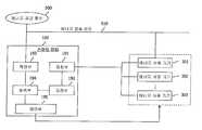
도 1은 스마트 그리드의 개략도에 관한 것으로서, 스마트 그리드는 화력발전이나 원자력발전 또는 수력발전을 통하여 전력을 발생시키는 발전소와, 신재생에너지인 태양광 또는 풍력을 이용한 태양광 발전소와 풍력발전소를 포함한다.1 is a schematic diagram of a smart grid, a smart grid includes a power plant that generates power through thermal power, nuclear power or hydropower, and a solar power plant and a wind power plant using solar or wind power as renewable energy. .
그리고, 상기 화력발전 또는 원자력발전소 또는 수력발전소는 송전선을 통하여 전력소로 전력을 보내고, 전력소에서는 변전소로 전기를 보내어 전기가 가정이나 사무실 같은 수요처로 분배되도록 한다.In addition, the thermal power plant or nuclear power plant or hydroelectric power station transmits power to a power station through a transmission line, and the power station sends electricity to a substation so that the electricity is distributed to a demand destination such as a home or an office.
그리고, 신재생 에너지에 의하여 생산된 전기도 변전소로 보내져 각 수요처로 분배되도록 한다. 그리고, 변전소에서 송전된 전기는 전력저장장치를 거쳐서 삼무실이나 각 가정으로 분배된다.The electricity produced by the renewable energy is also sent to substations to be distributed to each customer. The electricity transmitted from the substation is distributed to the office or each household via the power storage device.
가정용 전력관리네트워크(HAN, Home Area Network)를 사용하는 가정에서도 태양광이나 PHEV(하이브리드 전기자동차, Plug in Hybrid Electric Vehicle)에 장착된 연료전지를 통하여 전기를 자체적으로 생산하여 전기를 자체 공급할 수 있고, 남는 전기는 외부에 되팔수도 있다.Even in homes that use the Home Area Network (HAN), they can produce their own electricity through fuel cells mounted on solar power or a plug-in hybrid electric vehicle (PHEV). The remaining electricity can be resold to the outside.
그리고, 사무실이나 가정에는 스마트 계측장치가 마련되어서 각 수요처에서 사용되는 전력 및 전력요금을 실시간을 파악할 수 있고, 이를 통하여 사용자는 현재 사용되는 전력량 및 전력요금을 인지하여 상황에 따라 전력소모량이나 전력요금을 줄이는 방안을 강구할 수 있다.In addition, smart measuring devices are installed in offices and homes to grasp real-time power and power bills used by each customer, and through this, the user recognizes the amount of power and power bills currently used, and according to the situation, power consumption or power bills. Measures to reduce the
한편, 상기 발전소, 전력소, 저장장치 및 수요처는 양방향 통신이 되기 때문에 수요처에서 일방적으로 전기를 받도록 하는 것만을 떠나서, 수요처의 상황을 저장장치, 전력소, 발전소로 통지함으로써 수요처의 상황에 맞게 전기 생산 및 전기분배를 수행할 수 있게 된다.On the other hand, since the power plant, power station, storage device and the source of demand are bidirectional communication, only the unilaterally receive electricity from the source of demand, and notify the storage, power station, and power plant of the demand source to produce electricity according to the situation of the source of demand. Electric distribution can be performed.
한편, 상기 스마트 그리드에서는 수요처의 실시간 전력관리 및 소요전력의 실시간 예측을 담당하는 에너지관리장치(EMS, Energy Management System) 및 전력의 소모량을 실시간으로 계측하는 계측장치(AMI, Advanced Metering infrastructure)가 중추적인 역할을 담당한다.Meanwhile, in the smart grid, an energy management system (EMS), which is responsible for real-time power management and real-time prediction of power demand, and a measuring device (AMI), which measures power consumption in real time, are pivotal. Play a role of person.
여기서 스마트 그리드 하에서의 계측장치는 오픈 아키텍쳐를 근거로 하여 소비자를 통합하려는 기반기술로서 소비자에게는 전기를 효율적으로 사용하도록 하고, 전력공급자에게는 시스템상의 문제를 탐지하여 시스템을 효율적으로 운영할 수 있는 능력을 제공한다.Here, the measuring device under the smart grid is a basic technology for integrating consumers on the basis of open architecture, and provides consumers with the ability to efficiently use electricity, and provides power providers with the ability to operate the system efficiently by detecting problems in the system. do.
여기서, 오픈아키텍쳐란 일반적인 통신망과는 달리 스마트 그리드 시스템에서 전기기구가 어느 제조업체에서 제조되었는지 상관없이 모든 전기기구가 서로 연결될 수 있도록 하는 기준을 의미한다.Here, the open architecture, unlike a general communication network, refers to a standard that allows all electric devices to be connected to each other regardless of which manufacturer the electric device is manufactured in a smart grid system.
따라서, 상기 스마트 그리드에서 사용되는 계측장치는 "가격 대 장치(Prices to Devices)" 와 같은 소비자 친화적인 효율성 개념을 가능케 한다.Thus, the instrumentation used in the smart grid enables a consumer friendly efficiency concept such as "Prices to Devices."
즉, 전력시장의 실시간 가격신호가 각 가정에 설치된 에너지관리장치(EMS)를 통하여 중계되며, 에너지관리장치(EMS)는 각 전기장치와 통신을 하며 이를 제어하므로 사용자는 에너지관리장치(EMS)를 보고 각 전기장치의 전력정보를 인식하고 이를 기초로 소모전력량이나 전력요금 한계설정 등과 같은 전력정보처리를 수행함으로써 에너지 및 비용을 절약할 수 있다.That is, the real-time price signal of the electric power market is relayed through the energy management device (EMS) installed in each home, and the energy management device (EMS) communicates with and controls each electric device so that the user can control the energy management device (EMS). By recognizing the power information of each electric device and performing the power information processing such as the amount of power consumption or the limit of the power bill, the energy and cost can be saved.
여기서 에너지관리장치(EMS)는 사무실이나 가정에서 사용되는 로컬에너지관리장치(EMS)와, 상기 로컬에너지관리장치(EMS)와 양방향 통신을 하여 로컬에너지관리장치(EMS)에서 취합된 정보를 처리하는 중앙에너지관리장치(EMS)로 구성되는 것이 바람직하다.The energy management device (EMS) is a local energy management device (EMS) used in the office or at home, and the local energy management device (EMS) by performing bidirectional communication to process the information collected from the local energy management device (EMS) It is preferably composed of a central energy management device (EMS).
스마트 그리드에서 공급자와 수요자간의 전력정보에 관한 실시간 통신이 가능하게 되기 때문에, "실시간 전력망 반응"을 현실화 시킬 수 있고, 이에 따라서, 피크 수요(peak demand)를 맞추는데 소요되는 높은 비용을 줄일 수 있다.The smart grid enables real-time communication of power information between suppliers and consumers, enabling "real-time grid response" to be realized, thereby reducing the high cost of meeting peak demand.
따라서, 본 명세서에서 제시하려는 기술의 목적은 스마트 그리드를 이용하여 데이터 통신을 가능하게 하는 것이다.Accordingly, an object of the technology to be presented herein is to enable data communication using a smart grid.
또한, 본 명세서에서 제시하려는 기술의 다른 목적은 스마트 그리드에 대한 다양한 정보를 다양한 클라우드 서비스를 통해 이용할 수 있게 하는 것을 목적으로 한다.In addition, another object of the technology to be presented herein is to make various information about the smart grid available through various cloud services.
전술한 목적을 달성하기 위하여, 본 명세서의 일 개시에 의하면 스마트 그리드를 이용하여 홈 네트워크를 형성하여, 데이터 통신을 가능하게 한다.In order to achieve the above object, according to one disclosure of the present specification to form a home network using a smart grid, to enable data communication.
또한, 전술한 다른 목적을 달성하기 위하여, 본 명세서의 다른 개시에 이하면, 스마트 그리드 장비, 예컨대 스마트 미터(또는 에너지관리장치)가 다양한 클라우드 서비스를 접속할 수 있게 한다.In addition, in order to achieve the above-mentioned other objects, following another disclosure of the present specification, a smart grid device, such as a smart meter (or an energy management device), can be connected to various cloud services.
보다 구체적으로, 본 명세서의 일 개시에 의하면 전력 계측을 수행하는 스마트 미터에서의 서비스 수행 방법이 제공된다. 상기 서비스 수행 방법은 전력 사용에 대한 제1 정보를 제1 서비스의 서버로 전송하는 단계와; 상기 제1 서비스 상에서 사용자로부터 제2 서비스에 대한 요청을 수신하는 단계와; 상기 제2 서비스의 서버로 전력 사용에 관한 제2 정보를 전송하는 단계와; 상기 제2 서비스의 서버로부터 전력 사용에 관한 제3 정보를 수신하는 단계와; 상기 제3 정보를 상기 제1 서비스 상에서 상기 사용자로 전달하기 위해, 상기 제1 서비스의 서버로 전송하는 단계를 포함할 수 있다.More specifically, according to one disclosure of the present specification, a method of performing a service in a smart meter that performs power measurement is provided. The service performing method may further include transmitting first information on power usage to a server of a first service; Receiving a request for a second service from a user on the first service; Transmitting second information regarding power usage to a server of the second service; Receiving third information regarding power usage from a server of the second service; And transmitting the third information to the server of the first service to deliver the third information to the user on the first service.
상기 제1 또는 제2 서비스는 클라우드 서비스 또는 소셜 네트워크 서비스일 수 있다.The first or second service may be a cloud service or a social network service.
상기 제1 정보를 제1 서비스의 서버로 전송하는 단계에서는 상기 제1 서비스 상에서 상기 스마트 미터가 가진 계정을 통해 상기 제1 정보를 전송할 수 있다.In the transmitting of the first information to the server of the first service, the first information may be transmitted through an account of the smart meter on the first service.
상기 제1 서비스 상에는 사용자의 계정이 등록되어 있고, 상기 스마트 미터의 계정과 상기 사용자의 계정은 서로 친구 또는 이웃 관계로 설정되어 있을 수 있다.An account of a user may be registered on the first service, and the account of the smart meter and the account of the user may be set as friends or neighbors.
상기 제1 정보 및 제2 정보 중 하나 이상은 전력 사용 패턴 및 그에 따른 전력 사용 요금 정보일 수 있다.At least one of the first information and the second information may be a power usage pattern and power usage fee information.
상기 제2 서비스는 기존 전력 사용 패턴을 분석하고, 기존 전력 사용 패턴에 대한 개선을 제안하는 서비스일 수 있다.The second service may be a service that analyzes an existing power usage pattern and proposes an improvement on the existing power usage pattern.
한편, 본 명세서의 일 개시에 의하면 전력 계측을 수행하는 스마트 미터가 제공된다. 상기 스마트 미터는 외부와 데이터 통신을 수행하는 통신부와; 전력 사용량을 검침하는 검침부와; 상기 통신부를 통해 서비스를 수행하는 서비스 담당부를 포함할 수 있다. 상기 서비스 담당부는 상기 서비스 담당부는 각 서비스 별로 구비되는 복수의 서비스 클라이언트 플러그인부와, 상기 복수의 서비스 클라이언트 플러그인부를 통합하는 서비스 브로커부와, 상기 스마트 미터에 의해 생성되는 정보를 상기 서비스 브로커부로 통합하여 제공하는 서비스 계층부를 포함할 수 있다.On the other hand, according to one disclosure of the present specification, a smart meter for performing power measurement is provided. The smart meter is a communication unit for performing data communication with the outside; A meter reading unit for metering power usage; It may include a service manager for performing a service through the communication unit. The service manager may include a plurality of service client plug-ins provided for each service, a service broker unit for integrating the plurality of service client plug-ins, and the information generated by the smart meter to the service broker unit. It may include a service layer providing.
상기 복수의 서비스 클라이언트 플러그인부 중 제1 플러그인부가 전력 사용에 대한 제1 정보를 제1 서비스의 서버로 전송하고, 상기 제1 서비스 상에서 사용자로부터 제2 서비스에 대한 요청을 수신하면, 상기 서비스 브로커부로 전달할 수 있다. 그리고 상기 서비스 브로커부는 제2 플러그인부를 제어하여, 상기 제2 서비스의 서버로 전력 사용에 관한 제2 정보를 전송하고, 상기 제2 서비스의 서버로부터 전력 사용에 관한 제3 정보를 수신하면, 다시 상기 제1 플러그인부로 전달하여, 상기 제1 서비스의 서버로 전송할 수 있다.A first plug-in of the plurality of service client plug-ins transmits first information on power usage to a server of a first service, and receives a request for a second service from a user on the first service. I can deliver it. The service broker unit controls a second plug-in unit to transmit second information about power usage to a server of the second service, and when receiving the third information about power usage from a server of the second service, the service plug-in again. By transferring to the first plug-in unit, it may be transmitted to the server of the first service.
본 명세서의 일 개시에 의하면 스마트 그리드를 이용하여 홈 네트워크를 형성하여, 데이터 통신을 가능하게 한다.According to one disclosure of the present specification, a home network is formed using a smart grid to enable data communication.
본 명세서의 다른 개시에 이하면, 스마트 그리드 장비, 예컨대 스마트 미터(또는 에너지관리장치)가 다양한 클라우드 서비스를 접속할 수 있게 한다.Following another disclosure of this specification, a smart grid device, such as a smart meter (or energy management device), can access various cloud services.
도 1은 스마트 그리드의 개략도이다.
도 2는 본 발명에 따른 에너지 관리 시스템의 일 실시예를 나타낸단.
도 3은 본 발명에 따른 에너지 관리 시스템의 또 다른 실시예를 나타낸다.
도 4는 스마트 그리드의 주요 수요처인 가정에서 스마트 미터(또는 에너지관리장치(EMS))(100)가 설치된 예를 나타낸다.
도 5는 가정에서 스마트 미터(또는 에너지관리장치(EMS))(100)를 이용하여, 홈 네트워크를 구성한 예를 나타낸다.
도 6은 본 발명의 일 실시예에 따라 스마트 미터(또는 에너지관리장치(EMS))(100)가 클라우드 서비스에 연결되는 예를 나타낸다.
도 7은 본 발명의 다른 실시예에 따라 스마트 미터(또는 에너지관리장치(EMS))(100)가 클라우드 서비스에 연결되는 예를 나타낸다.
도 8은 도 7에 도시된 스마트 미터(또는 에너지관리장치(EMS))(100)가 다양한 클라우드 서비스를 이용하는 예를 나타낸다.
도 9는 스마트 미터(또는 에너지관리장치(EMS))(100)가 복수의 서비스에 접속하는 예를 나타낸 흐름도이다.
도 10은 도 9에 따라 사용자가 복수의 서비스를 이용하는 예를 나타낸다.
도 11은 본 발명의 또 다른 실시예에 따라 스마트 미터(또는 에너지관리장치(EMS))(100)와 디지털 방송 수신기(300)가 융합된 그림을 나타낸 구성도이다.
도 12는 도 11의 디지털 방송 수신기가 디스플레이하는 일 화면 구성을 나타내는 도면이다.1 is a schematic diagram of a smart grid.
Figure 2 shows an embodiment of an energy management system according to the present invention.
3 shows another embodiment of an energy management system according to the invention.
4 shows an example in which a smart meter (or energy management device (EMS)) 100 is installed in a home that is a major consumer of a smart grid.
5 shows an example of configuring a home network using a smart meter (or energy management device (EMS)) 100 in a home.
6 illustrates an example in which a smart meter (or energy management device) 100 is connected to a cloud service according to an embodiment of the present invention.
7 illustrates an example in which a smart meter (or energy management device) 100 is connected to a cloud service according to another embodiment of the present invention.
8 illustrates an example in which the smart meter (or energy management device (EMS)) 100 illustrated in FIG. 7 uses various cloud services.
9 is a flowchart illustrating an example in which the smart meter (or energy management device) 100 accesses a plurality of services.
10 illustrates an example in which a user uses a plurality of services according to FIG. 9.
FIG. 11 is a diagram illustrating a configuration in which a smart meter (or energy management device) 100 and a
FIG. 12 is a diagram illustrating a screen configuration displayed by the digital broadcast receiver of FIG. 11.
본 명세서에서 사용되는 기술적 용어는 단지 특정한 실시 예를 설명하기 위해 사용된 것으로, 본 발명을 한정하려는 의도가 아님을 유의해야 한다. 또한, 본 명세서에서 사용되는 기술적 용어는 본 명세서에서 특별히 다른 의미로 정의되지 않는 한, 본 발명이 속하는 기술 분야에서 통상의 지식을 가진 자에 의해 일반적으로 이해되는 의미로 해석되어야 하며, 과도하게 포괄적인 의미로 해석되거나, 과도하게 축소된 의미로 해석되지 않아야 한다. 또한, 본 명세서에서 사용되는 기술적인 용어가 본 발명의 사상을 정확하게 표현하지 못하는 잘못된 기술적 용어일 때에는, 당업자가 올바르게 이해할 수 있는 기술적 용어로 대체되어 이해되어야 할 것이다. 또한, 본 발명에서 사용되는 일반적인 용어는 사전에 정의되어 있는 바에 따라, 또는 전후 문맥상에 따라 해석되어야 하며, 과도하게 축소된 의미로 해석되지 않아야 한다.It is to be noted that the technical terms used herein are merely used to describe particular embodiments, and are not intended to limit the present invention. It is also to be understood that the technical terms used herein are to be interpreted in a sense generally understood by a person skilled in the art to which the present invention belongs, Should not be construed to mean, or be interpreted in an excessively reduced sense. In addition, when the technical terms used herein are incorrect technical terms that do not accurately express the spirit of the present invention, they should be replaced with technical terms that can be understood correctly by those skilled in the art. In addition, the general terms used in the present invention should be interpreted according to a predefined or prior context, and should not be construed as being excessively reduced.
또한, 본 명세서에서 사용되는 단수의 표현은 문맥상 명백하게 다르게 뜻하지 않는 한, 복수의 표현을 포함한다. 본 출원에서, "구성된다" 또는 "포함한다" 등의 용어는 명세서 상에 기재된 여러 구성 요소들, 또는 여러 단계들을 반드시 모두 포함하는 것으로 해석되지 않아야 하며, 그 중 일부 구성 요소들 또는 일부 단계들은 포함되지 않을 수도 있고, 또는 추가적인 구성 요소 또는 단계들을 더 포함할 수 있는 것으로 해석되어야 한다.Also, the singular forms "as used herein include plural referents unless the context clearly dictates otherwise. In the present application, the term "comprising" or "comprising" or the like should not be construed as necessarily including the various elements or steps described in the specification, Or may be further comprised of additional components or steps.
또한, 본 명세서에서 사용되는 구성요소에 대한 접미사 "모듈" 및 "부"는 명세서 작성의 용이함만이 고려되어 부여되거나 혼용되는 것으로서, 그 자체로 서로 구별되는 의미 또는 역할을 갖는 것은 아니다.Further, the suffix "module" and "part" for the components used in the present specification are given or mixed in consideration of ease of description, and do not have their own meaning or role.
또한, 본 명세서에서 사용되는 제1, 제2 등과 같이 서수를 포함하는 용어는 다양한 구성 요소들을 설명하는데 사용될 수 있지만, 상기 구성 요소들은 상기 용어들에 의해 한정되어서는 안 된다. 상기 용어들은 하나의 구성요소를 다른 구성요소로부터 구별하는 목적으로만 사용된다. 예를 들어, 본 발명의 권리 범위를 벗어나지 않으면서 제1 구성요소는 제2 구성 요소로 명명될 수 있고, 유사하게 제2 구성 요소도 제1 구성 요소로 명명될 수 있다.Furthermore, terms including ordinals such as first, second, etc. used in this specification can be used to describe various elements, but the elements should not be limited by the terms. The terms are used only for the purpose of distinguishing one component from another. For example, without departing from the scope of the present invention, the first component may be referred to as a second component, and similarly, the second component may also be referred to as a first component.
이하, 첨부된 도면을 참조하여 본 발명에 따른 바람직한 실시예를 상세히 설명하되, 도면 부호에 관계없이 동일하거나 유사한 구성 요소는 동일한 참조 번호를 부여하고 이에 대한 중복되는 설명은 생략하기로 한다.Hereinafter, exemplary embodiments of the present invention will be described in detail with reference to the accompanying drawings, wherein like reference numerals refer to like or similar elements throughout the several views, and redundant description thereof will be omitted.
또한, 본 발명을 설명함에 있어서 관련된 공지 기술에 대한 구체적인 설명이 본 발명의 요지를 흐릴 수 있다고 판단되는 경우 그 상세한 설명을 생략한다. 또한, 첨부된 도면은 본 발명의 사상을 쉽게 이해할 수 있도록 하기 위한 것일 뿐, 첨부된 도면에 의해 본 발명의 사상이 제한되는 것으로 해석되어서는 아니 됨을 유의해야 한다.In the following description, well-known functions or constructions are not described in detail since they would obscure the invention in unnecessary detail. It is to be noted that the accompanying drawings are only for the purpose of facilitating understanding of the present invention, and should not be construed as limiting the scope of the present invention with reference to the accompanying drawings.
도 2은 본 발명에 따른 에너지 관리 시스템의 일 실시예를 나타내고, 도 3는 본 발명에 따른 에너지 관리 시스템의 또 다른 실시예를 나타낸다.2 shows one embodiment of an energy management system according to the invention, and FIG. 3 shows another embodiment of an energy management system according to the invention.
도 2을 참조하자면, 에너지 공급 회사(500)가 공급하는 에너지는 에너지 전송 선로(510)를 따라 에너지 소비처인 가정으로 인입되어 각종 에너지 사용 기기(301,302, 303)에서 사용된다.Referring to FIG. 2, the energy supplied by the
상기 에너지 소비처인 가정에는 스마트 미터(또는 에너지관리장치(EMS)) (100)가 설치된다.A smart meter (or energy management device (EMS)) 100 is installed in the home that is the energy consumer.
상기 스마트 미터(또는 에너지관리장치(EMS))(100)는 상기 에너지 사용 기기(301, 302, 303)를 통해 에너지가 사용되는 정보, 예컨대 에너지 사용량을 검출하는 전자식 계량기이다.The smart meter (or energy management device (EMS)) 100 is an electronic meter that detects information on which energy is used, such as energy usage, through the
본 발명에 따른 상기 스마트 미터(또는 에너지관리장치(EMS))(100)은 적어도 검침부(191), 저장부(192), 측정부(193), 예측부(194)을 포함하여 이루어진다.The smart meter (or energy management device (EMS)) 100 according to the present invention comprises at least a
상기 스마트 미터(또는 에너지관리장치(EMS))(100) 내의 검침부(191), 저장부(192), 측정부(193), 예측부(194) 중 하나 이상은 일체적으로 구성되어 타 구성요소와 통신하면서 그 역할을 수행하도록 구성될 수 있다.At least one of the
상기 스마트 미터(또는 에너지관리장치(EMS))(100)는 상기 예측부(194)에서의 예측 결과에 따라 에너지 소비처의 에너지 사용 기기(301, 302, 303)를 제어하는 제어부(195)을 더 포함하여 이루어질 수 있다.The smart meter (or energy management device) 100 further controls a
도 3를 참조하자면, 저장부(192)과 예측부(194)의 역할은 중앙서버(600)가 수행하도록 구성될 수 있다.Referring to FIG. 3, the roles of the
중앙서버(600)는 에너지 공급 회사(500)가 에너지 관련 서비스를 제공하는 서버로서, 무선 메쉬(Mesh), 전력선 통신망, 인터넷망 등 다양한 통신망을 통해 에너지 가격 정보를 전송할 수 있다.The
에너지 사용 기기(301, 302, 303)는 에너지 공급 회사(400)에서 공급하는 에너지를 소비하는 장치이다. 구체적인 예로서 에너지가 전기인 경우 에너지 사용 기기는 냉장고, 티브이(TV) 세트, 난방기기, 냉방기기, 조명기기 등 전기를 이용하여 동작하는 기기이다.The
도 4는 스마트 그리드의 주요 수요처인 가정에서 스마트 미터(또는 에너지관리장치(EMS))(100)가 설치된 예를 나타낸다.4 shows an example in which a smart meter (or energy management device (EMS)) 100 is installed in a home that is a major consumer of a smart grid.
도 4를 참조하여 알 수 있는 바와 같이, 가정 내에는 각 가정에 공급되는 전력 및 전력요금을 실시간으로 측정할 수 있는 스마트 미터(또는 에너지관리장치(EMS))(100)가 설치될 수 있다.As can be seen with reference to Figure 4, a smart meter (or energy management device (EMS)) 100 that can measure in real time the power and power rates supplied to each home may be installed.
여기서 전력요금은 시간당 요금제를 기준으로 하여 과금될 수 있으며, 전력소모량이 급격하게 증대되는 시간 구간에서는 시간당 전력요금이 비싸지게 되거나, 전력소모량이 상대적으로 적은 심야 시간구간와 같은 때에는 시간당 전력요금이 저렴해질 수 있다.In this case, the electricity rate may be charged based on the hourly rate plan, and the hourly electricity rate becomes expensive in the time interval when the power consumption is rapidly increased, or when the power consumption is relatively low, such as a late night time period. Can be.
한편, 상기 가정 내에는 보조전원(400), 즉, 태양광 발전장치 등과 같은 자가발전시설과, 이러한 자가발전시설에서 발생하는 전력을 축전할 수 있는 축전지를 포함할 수 있다. 그리고, 상기 축전지 이외에 연료전지도 보조전원으로서의 역할을 할 수 있다. 여기서 보조전원은 전력회사와 같은 외부전원에서 전력을 공급받지 않는 상태에서 가정에 전력을 공급하는 역할을 한다.On the other hand, the home may include a
도 5는 가정에서 스마트 미터(또는 에너지관리장치(EMS))(100)를 이용하여, 홈 네트워크를 구성한 예를 나타낸다.5 shows an example of configuring a home network using a smart meter (or energy management device (EMS)) 100 in a home.
도 5를 참조하여 알 수 있는 바와 같이, 상기 스마트 미터(또는 에너지관리장치(EMS))(100)는 현재의 전기 소모상태 및 외부의 환경(온도, 습도)를 표시하는 화면을 구비하고, 사용자의 조작이 가능한 입력 버튼 등을 구비한 단말기 형태로 마련될 수 있다.As can be seen with reference to Figure 5, the smart meter (or energy management device (EMS)) 100 has a screen to display the current electricity consumption state and the external environment (temperature, humidity), the user It may be provided in the form of a terminal having an input button and the like that can be operated.
이러한 상기 스마트 미터(또는 에너지관리장치(EMS))(100)는 인터넷에 연결되어 있으며, 다시 가정 내부의 홈 네트워크 망을 통하여 냉장고, 세탁기 또는 건조기, 에어컨, TV 또는 조리기기와 같은 홈 어플라이언스 제품과 양방향 통신을 할 수 있다. 또한, 상기 스마트 미터(또는 에너지관리장치(EMS))(100)는 AP(Access Point)와 연결되어, 사용자의 휴대 기기와 네트워크를 형성하고, 상기 네트워크를 통해 서로 연결될 수 있다.The smart meter (or energy management device) 100 is connected to the Internet, and is again connected to a home appliance product such as a refrigerator, a washing machine or a dryer, an air conditioner, a TV or a cooking appliance through a home network in the home. Bidirectional communication is possible. In addition, the smart meter (or energy management device) 100 may be connected to an access point (AP) to form a network with a user's mobile device and may be connected to each other through the network.
이러한 홈 네트워크 구축에 사용되는 무선 근거리 통신 방식으로는 대표적으로 블루투스(Bluetooth), 지그비(Zigbee), 무선랜(Wireless LAN) 방식을 들 수 있다.Wireless short-range communication methods used in the home network construction include Bluetooth, Zigbee, and wireless LAN.
블루투스는 현재 전 세계적으로 가장 많은 이동통신 단말기에 탑재되고 있는 무선 PAN(Personal Area Network) 접속 기술로, 무선 핸즈프리, 스테레오 음악 스트리밍, 원 폰(One Phone) 등의 오디오 관련 통신 서비스뿐만 아니라 이동통신 단말기 간의 데이터 통신, 메시지 교환 등의 데이터 통신 서비스에 사용되고 있다. 블루투스(Bluetooth)는 저렴한 가격, 적은 전력 소모로 비교적 좁은 구역(10~100m) 내에서 여러 기기들 간의 자유로운 무선 통신이 가능하도록 해 주기 때문에 그 사용 범위가 증대되고 있다.Bluetooth is a wireless PAN (Personal Area Network) connection technology currently installed in the world's largest mobile communication terminals, and is a mobile communication terminal as well as audio-related communication services such as wireless hands-free, stereo music streaming, and one phone. It is used for data communication services such as data communication and message exchange. The range of use of Bluetooth is increasing because it enables free wireless communication between various devices within a relatively small area (10-100m) at a low price and low power consumption.
지그비 통신은 가정이나 사무실에 구축된 네트워크상에 존재하는 조명 기기나 에어콘, TV 수상기 등의 가전기기를 제어하기 위한 용도로 사용이 확산되고 있다. 지그비 통신 또한 저가, 저전력으로 무선 기기 제어를 구현한다는 점에서 장점을 가지고 있어서 홈 네트워크를 구축할 시에 많이 사용될 것으로 예상된다.ZigBee communication has been widely used for controlling home appliances such as lighting devices, air conditioners, TV receivers, and the like that exist on networks established in homes and offices. ZigBee communication also has the advantage of implementing wireless device control at low cost and low power, so it is expected to be widely used when building a home network.
무선랜은 IEEE 802.11에 기반한 통신 기술로서, 현재 가장 광범위하게 사용되고 있다.WLAN is a communication technology based on IEEE 802.11, and is currently used most widely.
이와 같이, 홈 네트워크는 가정 내의 가전제품, 즉 냉장고, 세탁기, 건조기, 에어컨, TV 또는 조리기기와 같은 홈 어플라이언스 제품 등을 하나로 연결한다. 따라서, 홈 네트워크 내부에서는 물론 외부에서도 인터넷이나 전화선을 통해 가정 내에 구축된 네트워크에 접속하여 컴퓨터나 디지털 텔레비전 수상기, 디지털 비디오 플레이어, 냉/난방기 등 모든 디지털 가전제품을 제어할 수 있도록 구성된다.As such, the home network connects home appliances such as refrigerators, washing machines, dryers, air conditioners, home appliance products such as TVs or cooking appliances into one. Therefore, it is configured to control all digital home appliances such as a computer, a digital television receiver, a digital video player, an air conditioner, and the like by accessing a network built in a home through the Internet or a telephone line both inside and outside the home network.
이와 같이, 상기 스마트 미터(또는 에너지관리장치(EMS))(100)는 다수의 네트워크를 형성할 수 있고, 각 네트워크에 접속할 수 있다.As such, the smart meter (or energy management device) 100 may form a plurality of networks, and may connect to each network.
그리고, 상기 스마트 미터(또는 에너지관리장치(EMS))(100)는 현재의 전기 소모상태, 예컨대 각 기기의 전기 소모 상태(즉, on/off 상태 및 on일 경우 소모량)와 내부 및 외부의 환경(온도, 습도) 등에 대한 정보를 인터넷을 통해 외부에 제공할 수 있다.In addition, the smart meter (or energy management device (EMS)) 100 is a current electricity consumption state, for example, the electricity consumption state of each device (that is, the on / off state and the consumption when on) and the internal and external environment Information about (temperature, humidity) can be provided to the outside via the Internet.
도 6은 본 발명의 일 실시예에 따라 스마트 미터(또는 에너지관리장치(EMS))(100)가 클라우드 서비스에 연결되는 예를 나타낸다.6 illustrates an example in which a smart meter (or energy management device) 100 is connected to a cloud service according to an embodiment of the present invention.
최근 다양한 정보를 보다 편리하게 어디서나 이용할 수 있게 하기 위해 클라우드 서비스가 점차 보편화 되고 있다. 특히 스마트폰과 같은 스마트 기기들의 사용이 늘어나면서, 어디서나 클라우드 서비스에 접속하여 각종 정보 및 데이터를 이용하려는 사용자의 요구가 늘어나고 있다. 따라서, 각종 기기에 클라우드 서버에서 다양한 서비스를 받을 수 있게 하는 클라이언트를 탑재하는 경우가 많이 일어나고 있다.Recently, cloud services are becoming more and more common in order to make various information available more conveniently anywhere. In particular, as the use of smart devices such as smart phones is increasing, users' demand for accessing cloud services anywhere and using various information and data is increasing. Therefore, there are many cases in which various devices are equipped with a client that enables various services to be received from a cloud server.
도 6에 도시된 바와 같이, 본 발명의 일 실시예에 따르면, 스마트 미터(또는 에너지관리장치(EMS))(100)는 제조사/에너지공급자 클라우드 서비스에 접속하여, 스마트 미터의 각종 상태를 교환할 수 있다. 또한, 상기 제조사 클라우드 서비스는 상기 스마트 미터(또는 에너지관리장치(EMS))(100)에 대한 각종 정보를 교환할 수 있게 한다. 예를 들어, 상기 제조사/에너지공급자 클라우드 서비스도 마찬가지로, 요금 고지서 정보, 에너지 소비량 등에 관한 정보를 상기 스마트 미터(또는 에너지관리장치(EMS))(100)로부터 제공 받고, 이를 통계화하고 가공하여, 에너지 소비 패턴과 같은 다양한 통계 정보를 생성하고, 이를 사용자의 요청에 있을 때 외부 어디에서나 상기 사용자의 단말로 제공할 수 있도록 한다. 한편, 상기 제조사 클라우드 서비스는 펌웨어 정보, 동작 상태 여부에 대한 정보를 상기 스마트 미터로부터 제공받아 저장하고, 사용자의 요청에 있을 때 외부 어디에서나 상기 사용자의 단말로 제공할 수 있도록 한다. 또한, 상기 제조사 클라우드 서비스는 요금 에너지 소비량 등에 관한 정보를 상기 스마트 미터(또는 에너지관리장치(EMS))(100)로부터 제공 받고, 이를 통계화하고 가공하여, 에너지 소비 패턴과 같은 다양한 통계 정보를 생성하고, 이를 사용자의 요청에 있을 때 외부 어디에서나 상기 사용자의 단말로 제공할 수 있도록 한다. 또한, 상기 제조사 클라우드 서비스는 상기 에너지 공급자로부터 요금 고지서 정보, 발전량에 대한 정보와 같은 다양한 정보를 제공받아, 사용자에게 전달할 수도 있다.As shown in FIG. 6, according to an embodiment of the present invention, the smart meter (or energy management device (EMS)) 100 is connected to a manufacturer / energy provider cloud service to exchange various states of the smart meter. Can be. In addition, the manufacturer cloud service enables to exchange various information on the smart meter (or energy management device (EMS)) (100). For example, the manufacturer / energy provider cloud service likewise receives information on billing bill information, energy consumption, etc. from the smart meter (or energy management device (EMS)) 100, and statisticalize and process it, Various statistical information, such as energy consumption patterns, may be generated and provided to the user's terminal from anywhere outside the user's request. Meanwhile, the manufacturer cloud service receives and stores firmware information and information on an operation state from the smart meter, and provides the terminal to the user's terminal from anywhere outside the user's request. In addition, the manufacturer cloud service is provided with information on the rate energy consumption, etc. from the smart meter (or energy management device (EMS)) 100, and statistically processed and generate a variety of statistical information, such as energy consumption pattern And, when it is at the user's request, it can be provided to the user's terminal from anywhere outside. In addition, the manufacturer cloud service may receive a variety of information, such as bill information, the amount of power generation information from the energy provider, may be delivered to the user.
이를 위해, 본 발명의 일 실시예에 따른 스마트 미터(또는 에너지관리장치(EMS))(100)는 프로세서(110), 통신부(120), 기능부(130)를 포함할 수 있다.To this end, the smart meter (or energy management device (EMS)) 100 according to an embodiment of the present invention may include a
상기 통신부(120)는 물리 계층, 매체 접속 제어(MAC) 계층, 네트워크 계층을 포함할 수 있다.The
상기 기능부(130)는 상기 스마트 미터(또는 에너지관리장치(EMS))(100)의 핵심 기능을 담당하는 핵심 기능부를 포함할 수 있다. 여기서 핵심 기능은 전술한 바와 같이, 에너지의 소비 여부를 감지하는 검침부(192), 에너지의 소비량을 측정하는 측정부(193), 각종 에너지의 사용량을 제어하는 제어부(195)를 포함하는 것을 의미한다. 또한, 상기 핵심 기능은 전술한 바와 같이, 각종 정보를 저장하는 저장부(192)와 에너지의 사용량을 미리 예측하거나, 요금의 변동을 미리 예측하는 예측부(194)를 더 포함할 수 있다.The
한편, 상기 관리 기능부는 상기 스마트 미터(또는 에너지관리장치(EMS))(100)의 동작 상태, 이상 유무 등을 관리하는 역할을 수행한다.On the other hand, the management function is responsible for managing the operation state, the presence or absence of the smart meter (or energy management device (EMS)) 100, and the like.
이러한 상기 관리 기능부는 상기 스마트 미터(또는 에너지관리장치(EMS))(100)에서 제공가능한 다양한 정보를 클라우드 서비스로 제공할 수 있게 한다. 여기서 스마트 미터(또는 에너지관리장치(EMS))(100)에서 제공가능한 다양한 정보로는 동작 상태, 이상 유무 등에 관한 정보 뿐만 아니라, 전술한 현재의 전기 소모상태, 예컨대 각 기기의 전기 소모 상태(즉, on/off 상태 및 on일 경우 소모량)와 내부 및 외부의 환경(온도, 습도) 등에 대한 정보 등에 관한 정보이다.The management function enables to provide a variety of information provided by the smart meter (or energy management device (EMS)) 100 to the cloud service. Here, the various information that can be provided by the smart meter (or energy management device (EMS)) 100, as well as information on the operating state, whether there is an abnormality, and the like, as described above, the current electricity consumption state, for example, the electricity consumption state of each device (that is, , on / off status and consumption in case of on) and information on internal and external environment (temperature, humidity).
이와 같이, 본 발명의 일 실시예에 따르면, 스마트 미터(또는 에너지관리장치(EMS))(100)는 제조사/에너지공급자 클라우드 서비스로 다양한 정보를 제공하고, 사용자는 상기 제조사/에너지공급자 클라우드 서비스에 접속하여, 가정에 설치된 스마트 미터(또는 에너지관리장치(EMS))(100)의 정보를 어디서나 편리하게 이용할 수 있다.As such, according to an embodiment of the present invention, the smart meter (or energy management device (EMS)) 100 provides a variety of information to the manufacturer / energy provider cloud service, the user to the manufacturer / energy provider cloud service By connecting, the information of the smart meter (or energy management device (EMS)) 100 installed in the home can be conveniently used anywhere.
도 7은 본 발명의 다른 실시예에 따라 스마트 미터(또는 에너지관리장치(EMS))(100)가 클라우드 서비스에 연결되는 예를 나타낸다.7 illustrates an example in which a smart meter (or energy management device) 100 is connected to a cloud service according to another embodiment of the present invention.
먼저, 상기 제조사/에너지공급자 클라우드 서비스는 다소 폐쇄적인 특성으로 인하여, 다양한 정보를 재생산할 수 있도록 하는 부가적인 서비스의 지원이 약한 단점이 있다. 또한, 제조사의 클라우드 서비스는 특정 제조 회사에서 제조된 스마트 미터(또는 에너지관리장치(EMS))(100)를 위해 특화된 서비스를 제공하기 때문에, 다른 장비와의 호환성이 떨어질 수 있는 단점이 있다. 특히 한 사용자가 여러 개의 스마트 미터(또는 에너지관리장치(EMS))(100)에 대한 정보를 이용하려 하는 경우, 사용자는 각 제조사의 클라우드 서비스에 접속해야 하는 번거로움이 있다. 예를 들어, 사용자가 자신의 집 뿐만 아니라 부모님의 집, 자녀의 집에 에너지 사용량을 관리할 때, 각 집에 설치된 스마트 미터(또는 에너지관리장치(EMS))의 제조사가 서로 다르다면, 사용자는 서로 다른 제조사의 클라우드 서비스에 접속해야 하는 번거로움이 있다.First, the manufacturer / energy provider cloud service has a weak point because of the somewhat closed nature of the additional service to reproduce a variety of information. In addition, the cloud service of the manufacturer provides a specialized service for the smart meter (or energy management device (EMS)) 100 manufactured by a specific manufacturing company, there is a disadvantage that the compatibility with other equipment may be inferior. In particular, when a user wants to use information on several smart meters (or energy management devices (EMS)) 100, the user is troublesome to access the cloud service of each manufacturer. For example, when a user manages energy usage not only in his or her own home, but also in the parent's home or child's home, if the manufacturers of smart meters (or energy management devices) installed in each home are different, There is a hassle to access cloud services from different manufacturers.
이를 위해서, 본 발명의 다른 실시예에 따른 스마트 미터(또는 에너지관리장치(EMS))(100)는 도 7을 참조하여 알 수 있는 바와 같이, 제조사/에너지공급자 클라우드 서비스 뿐만 아니라, 써드파티(3rd Party) 클라우드 서비스 또는 소셜 네트워크 서비스와 같이 다양한 서비스에 접속할 수 있도록 한다.To this end, the smart meter (or energy management device (EMS)) 100 according to another embodiment of the present invention, as can be seen with reference to Figure 7, the manufacturer / energy provider cloud service, as well as third parties (3rd Party) Allows access to various services such as cloud services or social network services.
이와 같이, 스마트 미터(또는 에너지관리장치(EMS))(100)가 여러 클라우드 서비스 또는 소셜 네트워크 서비스에 접속하여, 정보를 교환함에 있어서, 동적으로 잘 연동할 수 있는 방안이 필요하다.As such, when the smart meter (or energy management device) 100 accesses various cloud services or social network services and exchanges information, there is a need for a method of dynamically interworking well.
간단하게 생각하면, 여러 클라우드 서비스 또는 소셜 네트워크 서비스를 위한 클라이언트 모듈을 스마트 미터(또는 에너지관리장치(EMS))(100)에 설치하면 되나, 이렇게 하게 되면, 동일한 정보에 대해서 각 클라이언트 모듈마다 반복하여 처리하기 때문에, 상기 프로세서(110)의 처리 부하가 증가하게 된다. 이를 위해서는 고성능의 프로세서(110)를 장착해야 하나, 이렇게 되면, 스마트 미터(또는 에너지관리장치(EMS))(100)의 단가가 증가하게 되는 문제점이 발생하게 될 뿐만 아니라, 스마트 미터(또는 에너지관리장치(EMS))(100)의 자체 소비 전력도 증가하게 되는 단점이 있다. 이와 같이 자체 소비 전력이 증가하게 되면, 스마트 미터(또는 에너지관리장치(EMS))(100)는 본래 다른 에너지 소비 기기의 전력 사용량을 측정하고, 그 소비량을 줄이기 위한 장비의 본질을 벗어나게 되는 것이므로, 그 문제는 심각해질 수 밖에 없다.In simple terms, a client module for multiple cloud services or social network services may be installed in a smart meter (or energy management device) 100, but in this case, the same information is repeated for each client module repeatedly. Because of the processing, the processing load of the
또한, 여러 클라우드 서비스 또는 소셜 네트워크 서비스를 위한 클라이언트 모듈을 스마트 미터(또는 에너지관리장치(EMS))(100)에 개별적으로 설치하는 것은 또 다른 문제가 있다. 예를 들어, 여러 클라우드 서비스 또는 소셜 네트워크 서비스는 자신만의 특화된 서비스를 위하여 여러 기능을 확장하고 있는데, 이에 발맞추기가 어렵게 된다.In addition, separately installing client modules for various cloud services or social network services in the smart meter (or energy management device (EMS)) 100 is another problem. For example, many cloud services or social network services are expanding various functions for their own specialized services, which are difficult to keep up with.
따라서, 본 발명의 다른 실시예에 따른 스마트 미터(또는 에너지관리장치(EMS))(100)는 클라우드 서비스/소셜 네트워크 서비스 담당부(135)를 두고, 상기 클라우드 서비스/소셜 네트워크 서비스 담당부(135) 내에는 여러 클라우드 서버에 동적으로 대응하기 위해 각각의 서버를 담당하는 클라이언트를 플러그인(plug-in)으로 만들고, 그 플러그인 들을 수용하고 시스템과 적정 cloud서버를 연결해주는 클라우드 서비스 브로커(cloud service broker), 일관된 인터페이스를 제공하는 Abstracted service 계층으로 세분화하여 구현한다.Accordingly, the smart meter (or energy management device (EMS)) 100 according to another embodiment of the present invention has a cloud service / social
먼저, 상기 플러그인은 클라우드별 클라이언트에서 최소 기능을 담당한다. 즉, 상기 플러그인은 외부 클라우드 서버들과 연결 시에는 그 서버들이 사용하고 있는 고유의 프로토콜(OpenAPI)를 처리하는 역할만을 담당한다. 이와 같은 상기 플러그인은 스크립트(script)나 설정 파일(configuration)에 의해 간단하게 동적으로 생성될 수 있다. First, the plug-in is responsible for the minimum function in the cloud-specific client. That is, the plug-in only plays a role of processing a unique protocol (OpenAPI) used by external servers when connecting to external cloud servers. Such a plug-in may be dynamically generated simply by a script or a configuration file.
상기 클라우드 서비스 브로커는 상기 플러그인들을 수용하는 역할을 담당하고, 각종 정보를 상기 외부 클라우드 서버의 API에 맞추어 가공한다. 즉, 상기 클라우드 서비스 브로커는 각종 정보에서 상기 외부 클라우드 서버의 API에 맞추어, 일부의 정보만을 추출하여, 상기 플러그인으로 전달한다. 상기 각종 정보는 상기 Abstracted Service 계층으로부터 전달된 것일 수 있다.The cloud service broker is responsible for accommodating the plug-ins, and processes various information in accordance with the API of the external cloud server. That is, the cloud service broker extracts only a part of the information from the various information in accordance with the API of the external cloud server and delivers it to the plug-in. The various information may be delivered from the abstracted service layer.
상기 Abstracted Service 계층은 상기 핵심 기능부로부터 각종 정보를 제공받아, 클라우드 서버 별로 상이한 기능을 일관된 인터페이스로 표현하여 처리한다.The Abstracted Service layer receives various information from the core function unit and processes different functions by expressing a consistent interface for each cloud server.
도 8은 도 7에 도시된 스마트 미터(또는 에너지관리장치(EMS))(100)가 다양한 클라우드 서비스를 이용하는 예를 나타낸다.8 illustrates an example in which the smart meter (or energy management device (EMS)) 100 illustrated in FIG. 7 uses various cloud services.
도 8을 참조하여 알 수 있는 바와 같이, 스마트 미터(또는 에너지관리장치(EMS))(100)는 다양한 클라우드 서비스에 접속할 수 있고, 사용자는 휴대 기기(200)를 통하여, 스마트 미터(또는 에너지관리장치(EMS))(100)의 각종 정보를 다양한 클라우드 서비스 및 소셜 네트워크 서비스를 통하여 이용할 수 있다.As can be seen with reference to Figure 8, the smart meter (or energy management device (EMS)) 100 can access a variety of cloud services, the user through the
예를 들어, 상기 스마트 미터(또는 에너지관리장치(EMS))(100)가 도시된 에너지 공급 회사 서버(500)로부터의 정전 예보를 제조사/에너지 공급자 클라우드 서비스로부터 제공받으면, 상기 정전 정보를 써드파티 클라우드 서비스 또는 소셜 네트워크 서비스를 통해, 상기 사용자의 단말(200)로 예컨대 푸쉬 서비스, SMS 서비스, 이메일 서비스 등을 통해 제공할 수 있다.For example, when the smart meter (or energy management device) 100 receives a power outage forecast from the illustrated energy
다른 예로서, 상기 스마트 미터(또는 에너지관리장치(EMS))(100)가 도시된 에너지 공급 회사 서버(500)로부터 가격 정보를 제조사/에너지 공급자 클라우드 서비스로부터 제공받으면, 상기 가격 정보를 써드파티 클라우드 서비스로 제공하고, 상기 써드파티 클라우드 서비스는 최적의 사용 패턴(예컨대, peak시간대의 전력 사용량 제어 패턴)을 산출하여, 상기 사용 패턴에 대한 정보를 상기 사용자의 단말(200)로 제공할 수 있다. 상기 사용자가 상기 단말(200)을 통해 상기 사용 패턴을 확인하고, 동의함을 알리면, 상기 써드파티 클라우드 서비스는 상기 사용 패턴을 상기 스마트 미터(또는 에너지관리장치(EMS))(100)로 전송한다. 그러면, 상기 스마트 미터(또는 에너지관리장치(EMS))(100)는 상기 사용 패턴에 따라서 각종 에너지 소비 장치들을 제어(예컨대 피크시간 이전에 미리 냉난방 온도를 조절하거나, 세탁기는 피크 시간 이후에 작동시키도록 제어)할 수 있다.As another example, when the smart meter (or energy management device) 100 receives price information from the illustrated energy
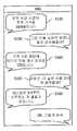
도 9은 스마트 미터(또는 에너지관리장치(EMS))(100)가 복수의 서비스에 접속하는 예를 나타낸 흐름도이고, 도 10은 도 9에 따라 사용자가 복수의 서비스를 이용하는 예를 나타낸다.FIG. 9 is a flowchart illustrating an example in which the smart meter (or EMS) 100 accesses a plurality of services, and FIG. 10 illustrates an example in which a user uses a plurality of services according to FIG. 9.
먼저, 도 9를 참조하여 알 수 있는 바와 같이, 상기 스마트 미터(또는 에너지관리장치(EMS))(100)는 복수의 서비스 중 제1 서비스 서버에 접속하여, 당일 전력 요금 정보 및 피크 시간대 정보를 수신한다(S110).First, as can be seen with reference to Figure 9, the smart meter (or energy management device (EMS)) (100) is connected to the first service server of a plurality of services, the power bill information and peak time zone information of the day Receive (S110).
이어서, 상기 스마트 미터(또는 에너지관리장치(EMS))(100)는 복수의 서비스 중 제2 서비스 서버(예컨대 소셜 네트워크 서비스)로 상기 수신한 정보를 전송한다(S120). 이때, 상기 스마트 미터(또는 에너지관리장치(EMS))(100)는 상기 제1 서비스 서버(예컨대 소셜 네트워크 서비스)에 자신만의 계정을 가지고 있다고 가정하자. 그리고, 상기 계정은 사용자의 계정과 친구 관계 또는 가까운 사이 관계로 설정되어 있다고 하자. 이 경우, 상기 정보의 전송으로 인하여, 상기 제2 서비스 서버에는 상기 스마트 미터의 계정으로 상기 정보가 개시된다. 이 경우, 상기 사용자는 자신의 휴대 기기를 통해 필요할 때, 자신의 계정을 이용하여 상기 제2 서비스 서버에 접속하여, 상기 스마트 미터의 계정에 의해 개시된 정보를 열람할 수 있다. 또는, 상기 각종 정보의 전송으로 인하여, 상기 제2 서비스 서버는 상기 정보를 상기 스마트 미터의 계정과 연결된 상기 사용자의 계정으로 푸쉬할 수 있다.Subsequently, the smart meter (or energy management device) 100 transmits the received information to a second service server (for example, a social network service) among a plurality of services (S120). In this case, it is assumed that the smart meter (or EMS) 100 has its own account in the first service server (eg, a social network service). And, it is assumed that the account is set as a friend relationship or a close relationship with the user's account. In this case, due to the transmission of the information, the second service server starts the information in the account of the smart meter. In this case, the user may access the second service server using his own account and read the information initiated by the account of the smart meter when necessary through his mobile device. Alternatively, due to the transmission of the various information, the second service server may push the information to an account of the user connected to the account of the smart meter.
예를 들어, 도 10과 같이 상기 스마트 미터(또는 에너지관리장치(EMS))(100)는 자신의 계정으로 당일 피크 시간대의 전력 가격 정보를 개시하면, 푸쉬에 의하여 상기 사용자의 휴대 기기의 화면에 표시된다.For example, as shown in FIG. 10, when the smart meter (or EMS) 100 starts the power price information of the peak time of the day with its own account, the smart meter (or energy management device (EMS)) 100 displays the screen of the user's mobile device by pushing. Is displayed.
이어서, 도 9과 같이, 상기 스마트 미터(또는 에너지관리장치(EMS))(100)는 사용자로부터 제3 서비스 요청을 수신할 수 있다(S130). 예를 들어, 도 10의 S130에 나타난 바와 같이, 상기 사용자는 오늘 요금이 얼마나 될지 분석해달라는 메시지를 상기 제2 서비스 서버를 통해 상기 스마트 미터(또는 에너지관리장치(EMS))(100)로 전송할 수 있다.Subsequently, as shown in FIG. 9, the smart meter (or EMS) 100 may receive a third service request from the user (S130). For example, as shown in S130 of FIG. 10, the user may transmit a message to the smart meter (or energy management device) 100 through the second service server to analyze how much the charge will be today. have.
그러면, 스마트 미터(또는 에너지관리장치(EMS))(100)는 상기 요금 정보 및 상기 시간대 정보 그리고 기존의 사용 패턴 정보를 제3 서비스 서버로 전송하여 당일 예상 요금에 대한 정보를 요청을 할 수 있다(S140).Then, the smart meter (or energy management device) 100 may request the information on the estimated fee on the day by transmitting the fee information, the time zone information, and the existing usage pattern information to a third service server. (S140).
상기 스마트 미터(또는 에너지관리장치(EMS))(100)가 상기 제3 서비스 서버로부터 당일 예상 요금에 대한 정보를 수신하면(S150), 이를 제2 서비스 서버로 전송하여 상기 사용자에게 다시 알려줄 수 있다.When the smart meter (or energy management device) 100 receives the information on the estimated fee for the day from the third service server (S150), the smart meter (or energy management device (EMS)) 100 may transmit the information to the second service server to notify the user again. .
한편, 도 9과 같이, 상기 스마트 미터(또는 에너지관리장치(EMS))(100)는 사용자로부터 제4 서비스 요청을 수신할 수 있다(S160). 예를 들어, 도 10의 S160에 나타난 바와 같이, 더 나은 사용 패턴을 제안해달라는 메시지를 상기 제2 서비스 서버를 통해 상기 스마트 미터(또는 에너지관리장치(EMS))(100)로 전송할 수 있다.On the other hand, as shown in Figure 9, the smart meter (or energy management device (EMS)) 100 may receive a fourth service request from the user (S160). For example, as shown in S160 of FIG. 10, a message for suggesting a better usage pattern may be transmitted to the smart meter (or EMS) 100 through the second service server.
그러면, 상기 스마트 미터(또는 에너지관리장치(EMS))(100)는 도 9에 도시된 바와 같이 제4 서비스 서버로 최적화된 사용 패턴을 요청할 수 있다(S170).Then, the smart meter (or energy management device) 100 may request the optimized usage pattern to the fourth service server as shown in FIG. 9 (S170).
그리고, 상기 스마트 미터(또는 에너지관리장치(EMS))(100)가 제4 서비스 서버로부터 최적화된 사용 패턴에 대한 정보를 수신하면(S180), 상기 최적화된 사용 패턴에 대한 정보를 제2 서비스 서버로 전송하여 상기 사용자에게 다시 알려줄 수 있다(S190). 예컨대, 도시된 바와 같이, 냉난방을 3시부터 가동하는 것을 제안하는 메시지를 사용자에게 전달할 수 있다.When the smart meter (or energy management device) 100 receives the information on the optimized usage pattern from the fourth service server (S180), the smart meter (or energy management apparatus (EMS)) 100 receives the information on the optimized usage pattern from the second service server. By transmitting to the user can be informed again (S190). For example, as shown, a message may be delivered to the user suggesting to run air conditioning from 3 o'clock.
이때, 만약 사용자가 상기 제안된 패턴에 대해서 동의하면, 상기 스마트 미터(또는 에너지관리장치(EMS))(100)는 상기 정보에 따라 전력 사용은 제어할 수 있다.In this case, if the user agrees with the proposed pattern, the smart meter (or energy management device) 100 may control power usage according to the information.
도 11은 본 발명의 또 다른 실시예에 따라 스마트 미터(또는 에너지관리장치(EMS))(100)와 디지털 방송 수신기(300)가 융합된 그림을 나타낸 구성도이다.FIG. 11 is a diagram illustrating a configuration in which a smart meter (or energy management device) 100 and a
도 11을 참조하면, 도 6 및 도 7과 달리 스마트 미터(또는 에너지관리장치(EMS))(100) 내에 있던 제어부(195)와 클라우드 서비스/소셜 네트워크 서비스 담당부(135)는 디지털 방송 수신기(300)내로 통합된다. 즉, 상기 스마트 미터(100)는 도 6 및 도 7과 같이 프로세서(110), 통신부(120), 기능부(130)를 포함하는데, 상기 기능부(130) 내에는 검침부(192)와 측정부(193)만이 구비되고, 제어부(195)와 클라우드 서비스/소셜 네트워크 서비스 담당부(135)는 디지털 방송 수신기(300) 내로 통합된다.Referring to FIG. 11, unlike FIG. 6 and FIG. 7, the
구체적으로, 각 기능과 동작을 설명하면 다음과 같다.Specifically, each function and operation will be described as follows.
상기 스마트 미터(또는 에너지관리장치(EMS))(100)는 에너지 공급 회사(500)로부터 스마트 그리드 정보를 수신한다. 그리고, 수신한 스마트 그리드 정보를 디지털 방송 수신기(300)로 전송한다. 상기 스마트 그리드 정보는 스마트 그리드 망 내에서 수집된 전력 정보이다. 스마트 그리드 정보는 실시간으로 책정되는 전력 가격 정보 또는 예측되는 전력 가격 정보를 포함하며, 소정 지역별 전력 사용량 또는 부수적인 전력 관련 정보(소정 지역으로 공급되는 총 전력 생산량 등) 등을 더 포함할 수 있다. 또한, 스마트 그리드 정보 내에 포함되는 전력 가격 정보는 소정 시간별 전력 가격 정보이다. 즉, 소정 시간 및 이에 대응되는 전력 가격이 연관되어 있어서, 스마트 그리드 정보 내의 전력 가격 정보는 다수개의 시점들 각각에 대응되는 전력 가격들에 대한 정보를 포함한다. 예를 들어, 에너지 공급 회사(500)가 전력 가격을 30 분 간격으로 예측 또는 결정한다면, 전력 가격 정보는 30분 간격을 갖는 다수의 시점들 각각에 대응되는 전력 가격을 포함한다. 여기서, 전력 가격 정보는 현재시간 이후의 전력 소비 예측량 및 전력 공급 예측량 등을 고려하여 책정될 수 있다.The smart meter (or energy management device) 100 receives smart grid information from the
또한, 스마트 그리드 정보는 에너지 공급 회사(500)에서 실시간으로 생성되므로, 상기 스마트 미터(또는 에너지관리장치(EMS))(100)는 스마트 그리드 정보를 실시간으로 전송받는다.In addition, since the smart grid information is generated in real time in the
한편, 이와 같이 상기 스마트 미터(또는 에너지관리장치(EMS))(100)가 스마트 그리드 정보를 수신하여, 상기 디지털 방송 수신기(300)로 전달할 수 있지만, 대안적으로 상기 디지털 방송 수신기(300)가 상기 에너지 공급 회사(500)로부터 상기 스마트 그리드 정보를 실시간으로 전송받을 수도 있다. 따라서, 디지털 방송 수신기(300)가 전송받는 스마트 그리드 정보는 일정 시간 간격으로 계속하여 업데이트 될 수 있다.Meanwhile, the smart meter (or energy management device) 100 may receive the smart grid information and transmit the smart grid information to the
한편, 상기 스마트 미터(또는 에너지관리장치(EMS))(100)는 상기 검침부(192)에서 검침한 전력 검침 정보를 디지털 방송 수신기(300)로 전송한다. 즉, 상기 검침부(192) 및 상기 측정부(193)는 실시간으로 일 가정 내 총 소비 전력을 측정한다. 상기 검침부(192) 및 상기 측정부(193)는 일별 누적 소비 전력, 또는 월별 누적 소비 전력 등 소정 기간별 가정 내 총 소비 전력을 검침하고, 검침한 정보인 전력 검침데이터를 출력할 수 있다. 상기 검침부(192) 및 상기 측정부(193)는 이와 같이 실시간으로 가정 내 소비전력을 모니터링한 데이터인 전력 검침 데이터를 실시간으로 상기 에너지 공급 회사(500) 및 사용자에게 제공한다.Meanwhile, the smart meter (or energy management device) 100 transmits the power meter reading information read by the
상기 디지털 방송 수신기(300)는 신호 수신부(310), 제어부(320), 신호 처리부(330), OSD 생성부(340), 및 디스플레이 부(350)를 포함한다.The
상기 신호 수신부(310)는 튜너(312) 및 인터페이스 부(314)를 포함한다. 그리고, 안테나(316)를 더 포함할 수 있다. 상기 안테나(316)는 방송국 또는 위성 등으로부터 송신되는 신호를 수신한다. 방송국 등은 고주파 신호(Radio frequency signal, 또는 '무선 주파수 신호'라 함)를 송신할 수 있으며, 그에 따라 안테나(316)는 고주파 신호를 수신한다. 상기 튜너(312)는 소정 채널을 통해 전송되는 프로그램을 수신받기 위하여, 소정 주파수를 갖는 수신 신호를 선택하여 수신한다. 여기서, 소정 주파수는 사용자 등이 선택한 채널에 따라서 달라진다.
The
상기 인터페이스 부(314)는 상기 스마트 미터(또는 에너지관리장치(EMS))(100) 또는 상기 에너지 공급 회사(500)로부터 전송되는 스마트 그리드 정보를 전송받는다. 그리고, 이를 제어부(320)로 전송한다. The
또한, 상기 인터페이스 부(314)는 상기 검침부(192) 및 상기 측정부(193)로부터 전력 검침 정보를 직접 전송받을 수 있다.Also, the
이와 같은 상기 인터페이스 부(314)는 외부로 신호를 송수신하기 위한 통신 장치로서, 유선 통신 장치 또는 무선 통신 장치가 이용될 수 있다. 무선 통신 장치로는 이더넷(Ethernet) 또는 전력선 통신(PLC: Power Line Communication) 등이 이용될 수 있으며, 무선 통신 장치로는 유선랜(Wireless Lan), 지그비(ZigBee) 통신기 등이 이용될 수 있다.The
상기 제어부(320)는 방송 수신기의 전반적인 기능을 제어하며, 오디오/비디오 디코더(336)에서 디코딩된 오디오 데이터 및 비디오 데이터가 디스플레이 부(350)에서 출력되도록 제어한다.The
그리고, 제어부(320)는 상기 인터페이스부(314)에서 수신된 스마트 그리드 정보를 전송받고 이를 저장시키고, 전송받은 스마트 그리드 정보에 대응되는 OSD(On Screen Display) 데이터의 생성을 제어한다.The
또한, 상기 제어부(320)는 스마트 그리드 제어부(195)를 구비할 수 있다. 이 경우, 스마트 그리드 제어부(322)가 전송된 스마트 그리드 정보의 저장 및 전송받은 스마트 그리드 정보에 대응되는 OSD(On Screen Display) 데이터의 생성을 제어할 수 있다.In addition, the
또한, 상기 제어부(320)는 전술한 바와 같이 클라우드 서비스/소셜 네트워크 서비스 담당부(135)를 포함할 수 있다.In addition, the
상기 신호 처리부(330)는 튜너(312)를 통하여 전송되는 수신 신호를 영상 및 음성 신호 처리하여 출력한다. 즉, 신호처리부(330)는 디지털 방송 수신기(300)의 디스플레이 부(350) 및 음성 출력 부(미도시)(예를 들어, 스피커)로 영상 또는 음성이 출력될 수 있도록, 입력된 영상 신호 또는 음성 신호를 방송국 등에서 송신한 원래의 영상 데이터로 복원하고 노이즈 제거 처리, 및 신호 품질 개선 처리 등을 수행한다.The
구체적으로, 상기 신호 처리부(330)는 복조부(332), 역 다중화부(334), 및 오디오/비디오 디코더(336)를 포함한다.In detail, the
상기 복조부(332)는 수신 신호를 중간 주파수 신호(IF 신호)로 변환하고, 변환된 중간 주파수 신호를 복조(demodulate)한다. 즉, 수신 신호를 방송국에서 전송하고자 했던 원래의 영상 신호로 회복시킨다. 복조부(332)에서 출력되는 데이터는 전송 스트림(TS: Transfer Stream) 형태의 데이터가 될 수 있다.The
역 다중화부(334)는 복조부(332)에서 복조된 방송신호로부터 오디오 데이터 및 비디오 데이터를 디멀티플렉싱(demultiplexing)한다. 또한, 복조된 방송 신호로부터 영상 데이터인 오디오 데이터 및 비디오 데이터 이외의 제어 데이터 또는 부가 데이터를 분리 추출한다.The
오디오 데이터, 및 비디오 데이터의 디멀티플렉싱은 제어부(320)에 의해 제어되 될 수 있다. 디멀티플렉싱 된오디오 데이터 및 비디오 데이터는, 오디오/비디오 디코더(336)로 전송된다.Demultiplexing of the audio data and the video data may be controlled by the
오디오/비디오 디코더(336)는 전송받은 데이터를 디코딩하여, 디스플레이 부(350)가 디스플레이할 수 있는 영상데이터(예를 들어, 프레임 데이터 형태)로 변환하여 출력한다.The audio /
상기 OSD 생성부(340)는 제어부(320)의 제어에 따라서, 디스플레이 부(350) 내에 구비되는 디스플레이 패널(미도시)상의 일부 영역에 디스플레이될 OSD 데이터를 생성한다. 또한, OSD 데이터는 디스플레이 패널 상에 디스플레이 되고 있는 영상 화면상의 소정 영역에 디스플레이될 수 있다.The
상기 OSD 생성부(340) 상기 제어부(320)의 제어에 따라서 스마트 그리드 정보에 대응되는 OSD 데이터를 생성한다. OSD 데이터는 소정 시간 간격을 갖는 소정 시간들 별 전력 가격 정보들을 포함한다. 추가적으로, 스마트 그리드 정보에 포함된 일 가정의 개별 전력 사용량 또는 소정 지역별 전력 사용량 정보들이 OSD 데이터 포함되어 디스플레이될 수 있다. 여기서, 하나의 가정은 이하의 도 3에 도시된 바와 같이 다수개의 전자기기를 포함하며, 전력을 공급받아 전술한 다수개의 전자 기기들을 구동시킨다.The
제어부(320)는 OSD 데이터가 영상 화면이 디스플레이되는 동안에 자동으로 디스플레이 되도록 제어할 수 있다. 또한, 제어부(320)는 스마트 그리드 정보에 대응되는 OSD 데이터의 디스플레이를 사용자가 요청한 경우, 이에 응답하여 소정 시간(예를 들어, 1분) 동안 영상 화면상의 소정 영역에 디스플레이되도록 제어할 수 있다. 또한, 제어부(320)는 스마트 그리드 정보에 대응되는 OSD 데이터가 일정 시간 간격(예를 들어, 1시간)으로 디스플레이화면상에 팝 업(pop-up) 형태 또는 베너(banner) 형태 등으로 디스플레이되도록 제어할 수 있다.The
OSD 데이터는 다양한 형태 및 색상을 가질 수 있으며, 디스플레이되는 위치 또한 다양하게 설정될 수 있다. 그리고, 영상 화면이 디스플레이되고 있는 동안에 OSD 데이터를 디스플레이할 경우, OSD 데이터는 영상 화면의 시청을 방해하지 않도록, 영상 화면의 둘레 영역 중 일부 영역 상에서 디스플레이될 수 있다.The OSD data may have various shapes and colors, and the displayed position may be variously set. When the OSD data is displayed while the video screen is being displayed, the OSD data may be displayed on a part of the peripheral area of the video screen so as not to disturb the viewing of the video screen.
디스플레이 부(350)는 내부적으로 구비되는 디스플레이 패널(미도시) 상으로 오디오/비디오 디코더(336)에서 출력되는 영상 데이터에 따른 영상 화면을 디스플레이한다. 또한, OSD 생성부(340)에서 생성되어 디스플레이 부(350)로 입력되는 OSD 데이터를 영상 화면상의 소정 영역에 디스플레이한다.The
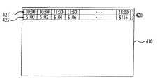
도 12는 도 11의 디지털 방송 수신기가 디스플레이하는 일 화면 구성을 나타내는 도면이다.FIG. 12 is a diagram illustrating a screen configuration displayed by the digital broadcast receiver of FIG. 11.
도 12를 참조하면, OSD 생성부(340)에서 생성된 OSD 데이터는 디스플레이 부(150)의 내부에 구비되는 디스플레이 패널(410) 상의 둘레 영역 중 상측 소정 영역(420 부분) 또는 하측 소정 영역에 디스플레이될 수 있다.Referring to FIG. 12, the OSD data generated by the
소정 시간(421)에 대응되는 전력 가격 정보(423)가 디스플레이되므로, OSD 데이터에서는 도 12에 도시된 바와 같이, 소정 시간 간격을 갖는 다수의 시점들인 10시, 10시 30분, 11시, 및 11시 30분에서의 전력 가격인 100 달러, 102 달러, 104 달러, 및 106 달러가 포함된다.Since the
디스플레이되는 OSD 데이터의 형식은 매우 다양하게 존재할 수 있다. 예를 들어, 전력 가격이 낮은 시간대 및 그에 대응되는 전력 가격과, 전력 가격이 높은 시간대 및 그에 대응되는 전력 가격을 별도의 색상으로 표시할 수 있다. 또한, 도 12에서는 시간 간격을 30분으로 하였으나, 도시되는 시간 간격은 사용자의 설정 에 따라서 달라질 수 있다.The format of the OSD data to be displayed can vary widely. For example, the time when the power price is low and the corresponding power price, and the time when the power price is high and the power price corresponding thereto may be displayed in separate colors. In addition, although the time interval is set to 30 minutes in FIG. 12, the illustrated time interval may vary according to the user's setting.
또한, 사용자의 조작 또는 자동 설정에 의하여, 한 화면에 디스플레이되지 않는 시간에서의 전력 정보가 디스플레이 되도록 할 수 있다. 예를 들어, 도 12에서 한 화면에 디스플레이되는 시간은 10시부터 18시까지이나, 사용자의 조작 또는 자동 설정에 의하여, 18시 이후의 시간에 대응되는 전력 정보를 포함하는 OSD 데이터가 도 11의 OSD 데이터에 후속하여 디스플레이되도록 할 수 있다.In addition, by the user's manipulation or automatic setting, power information at a time not displayed on one screen may be displayed. For example, the time displayed on one screen in FIG. 12 is from 10 o'clock to 18 o'clock, but OSD data including power information corresponding to the time after 18 o'clock is displayed by the user's operation or automatic setting. It can be displayed subsequent to the OSD data.
또한, 도 12에서는 OSD 데이터에 소정 시간에 대응되는 전력 가격 정보만이 포함된 경우를 예로 들어 도시하였으나, OSD 데이터에는 스마트 그리드 정보에 포함되는 소정 지역별 전력 사용량, 또는 전력 검침부(170)에서 측정된 전력 검침 정보 등이 더 포함되어 디스플레이될 수 있다.In addition, although FIG. 12 illustrates an example in which the OSD data includes only power price information corresponding to a predetermined time, the OSD data is measured by a predetermined region of power consumption included in the smart grid information or by the power meter reading unit 170. Power meter reading information, etc. may be further included and displayed.
발명에서는 디지털 방송 수신기(300)에서 스마트 그리드 정보를 전송받고 이에 대응되는 OSD 데이터가 디스플레이됨으로써, 사용자는 보다 편리하고 용이하게 전력 가격, 당해 가정 내에서의 전력 사용량, 이외의 전력관련 정보(소정 지역별 전력 사용량 등)을 알 수 있다. 그에 따라서, 사용자는 전력 가격이 최소가 되는 시점에서 가전 제품을 동작시키고 전력 가격이 높은 시점에서 전력 사용을 자제함으로써, 전력 요금을 절약할 수 있게 된다.In the present invention, the smart broadcast information is received from the
이상에서는 본 발명의 바람직한 실시예를 예시적으로 설명하였으나, 본 발명의 범위는 이와 같은 특정 실시예에만 한정되는 것은 아니므로, 본 발명은 본 발명의 사상 및 특허청구범위에 기재된 범주 내에서 다양한 형태로 수정, 변경, 또는 개선될 수 있다.While the present invention has been described with reference to exemplary embodiments, it is to be understood that the invention is not limited to the disclosed exemplary embodiments, but, on the contrary, May be modified, modified, or improved.
Claims (11)
Translated fromKorean전력 사용에 대한 제1 정보를 제1 서비스의 서버로 전송하는 단계와;
상기 제1 서비스 상에서 사용자로부터 제2 서비스에 대한 요청을 수신하는 단계와;
상기 제2 서비스의 서버로 전력 사용에 관한 제2 정보를 전송하는 단계와;
상기 제2 서비스의 서버로부터 전력 사용에 관한 제3 정보를 수신하는 단계와;
상기 제3 정보를 상기 제1 서비스 상에서 상기 사용자로 전달하기 위해, 상기 제1 서비스의 서버로 전송하는 단계를 포함하는 것을 특징으로 하는 서비스 수행 방법.As a method in a smart meter to perform power measurements,
Transmitting first information about power usage to a server of a first service;
Receiving a request for a second service from a user on the first service;
Transmitting second information regarding power usage to a server of the second service;
Receiving third information regarding power usage from a server of the second service;
Transmitting the third information to the server of the first service to deliver the third information to the user on the first service.
클라우드 서비스 또는 소셜 네트워크 서비스인 것을 특징으로 하는 서비스 수행 방법.The method of claim 1, wherein the first or second service is
Method of performing a service, characterized in that the cloud service or a social network service.
상기 제1 서비스 상에서 상기 스마트 미터가 가진 계정을 통해 상기 제1 정보를 전송하는 것을 특징으로 하는 서비스 수행 방법.The method of claim 1, wherein the transmitting of the first information to a server of a first service includes:
And transmitting the first information through an account of the smart meter on the first service.
상기 제1 서비스 상에는 사용자의 계정이 등록되어 있고,
상기 스마트 미터의 계정과 상기 사용자의 계정은 서로 친구 또는 이웃 관계로 설정되어 있는 것을 특징으로 하는 서비스 수행 방법.The method of claim 3,
The user's account is registered on the first service,
The account of the smart meter and the account of the user is a service performing method, characterized in that is set to each other friends or neighbors.
전력 사용 패턴 및 그에 따른 전력 사용 요금 정보인 것을 특징으로 하는 서비스 수행 방법.The method of claim 1, wherein at least one of the first information and the second information is
Service usage method characterized in that the power usage pattern and the power usage fee information accordingly.
기존 전력 사용 패턴을 분석하고, 기존 전력 사용 패턴에 대한 개선을 제안하는 서비스인 것을 특징으로 하는 서비스 수행 방법.The method of claim 1, wherein the second service is
A service performing method, characterized in that the service analyzing the existing power usage pattern, and proposes to improve the existing power usage pattern.
외부와 데이터 통신을 수행하는 통신부와;
전력 사용량을 검침하는 검침부와;
상기 통신부를 통해 서비스를 수행하는 서비스 담당부를 포함하고,
상기 서비스 담당부는 각 서비스 별로 구비되는 복수의 서비스 클라이언트 플러그인부와, 상기 복수의 서비스 클라이언트 플러그인부를 통합하는 서비스 브로커부와, 상기 스마트 미터에 의해 생성되는 정보를 상기 서비스 브로커부로 통합하여 제공하는 서비스 계층부를 포함하는 것을 특징으로 하는 스마트 미터.As a smart meter that performs power measurement,
A communication unit for performing data communication with the outside;
A meter reading unit for metering power usage;
A service department for performing a service through the communication unit;
The service manager includes a plurality of service client plug-ins provided for each service, a service broker unit integrating the plurality of service client plug-ins, and a service layer integrating and providing information generated by the smart meter to the service broker unit. Smart meter comprising a wealth.
상기 복수의 서비스 클라이언트 플러그인부 중 제1 플러그인부가 전력 사용에 대한 제1 정보를 제1 서비스의 서버로 전송하고, 상기 제1 서비스 상에서 사용자로부터 제2 서비스에 대한 요청을 수신하면, 상기 서비스 브로커부로 전달하고,
상기 서비스 브로커부는 제2 플러그인부를 제어하여, 상기 제2 서비스의 서버로 전력 사용에 관한 제2 정보를 전송하고, 상기 제2 서비스의 서버로부터 전력 사용에 관한 제3 정보를 수신하면, 다시 상기 제1 플러그인부로 전달하여, 상기 제1 서비스의 서버로 전송하는 것을 특징으로 하는 스마트 미터.The method of claim 7, wherein
A first plug-in of the plurality of service client plug-ins transmits first information on power usage to a server of a first service, and receives a request for a second service from a user on the first service. Pass it on,
The service broker unit controls a second plug-in unit to transmit second information about power usage to a server of the second service, and when receiving the third information about power usage from a server of the second service, the first plug-in. The smart meter, characterized in that for transmitting to the plug-in unit, and transmits to the server of the first service.
클라우드 서비스 또는 소셜 네트워크 서비스인 것을 특징으로 하는 스마트 미터.The method of claim 8, wherein the first or second service is
Smart meter, which is a cloud service or a social network service.
상기 제1 서비스 상에서 상기 스마트 미터가 가진 계정을 통해 상기 제1 정보를 제1 서비스의 서버로 전송하는 것을 특징으로 하는 스마트 미터.9. The method of claim 8,
Smart meter, characterized in that for transmitting the first information to the server of the first service through the account of the smart meter on the first service.
상기 제1 서비스 상에는 사용자의 계정이 등록되어 있고,
상기 스마트 미터의 계정과 상기 사용자의 계정은 서로 친구 또는 이웃 관계로 설정되어 있는 것을 특징으로 하는 스마트 미터.The method of claim 10,
The user's account is registered on the first service,
The account of the smart meter and the account of the user is a smart meter, characterized in that set to each other friends or neighbors.
Priority Applications (1)
| Application Number | Priority Date | Filing Date | Title |
|---|---|---|---|
| KR1020120012507AKR101890675B1 (en) | 2012-02-07 | 2012-02-07 | Smart meter for smart grid and method for performing service |
Applications Claiming Priority (1)
| Application Number | Priority Date | Filing Date | Title |
|---|---|---|---|
| KR1020120012507AKR101890675B1 (en) | 2012-02-07 | 2012-02-07 | Smart meter for smart grid and method for performing service |
Publications (2)
| Publication Number | Publication Date |
|---|---|
| KR20130100850Atrue KR20130100850A (en) | 2013-09-12 |
| KR101890675B1 KR101890675B1 (en) | 2018-08-22 |
Family
ID=49451375
Family Applications (1)
| Application Number | Title | Priority Date | Filing Date |
|---|---|---|---|
| KR1020120012507AExpired - Fee RelatedKR101890675B1 (en) | 2012-02-07 | 2012-02-07 | Smart meter for smart grid and method for performing service |
Country Status (1)
| Country | Link |
|---|---|
| KR (1) | KR101890675B1 (en) |
Cited By (6)
| Publication number | Priority date | Publication date | Assignee | Title |
|---|---|---|---|---|
| CN103941712A (en)* | 2014-05-13 | 2014-07-23 | 上海电气集团股份有限公司 | Autonomous cloud system adopting cloud electricity meters for transformer substation |
| WO2015060498A1 (en)* | 2013-10-25 | 2015-04-30 | 벽산파워 주식회사 | Group transaction service system and method for small scale demand response resources using open type power use history data based on social network service |
| KR101633969B1 (en)* | 2014-02-13 | 2016-06-27 | 주식회사 포스코아이씨티 | Building Energy Management System Based on Context-Aware and Method for Managing Energy of Building Using The Same |
| CN105978163A (en)* | 2016-07-12 | 2016-09-28 | 江西仪能新能源微电网协同创新有限公司 | Integrated energy efficiency monitoring treatment control system and method |
| WO2019182174A1 (en)* | 2018-03-21 | 2019-09-26 | 누리플렉스 홀딩스 아이엔씨 | Smart meter, system including same, and method for controlling smart meter |
| RU195281U1 (en)* | 2017-11-10 | 2020-01-22 | ООО "Электросетевые технологии" | Single board integrating Smart Grid elements |
Citations (2)
| Publication number | Priority date | Publication date | Assignee | Title |
|---|---|---|---|---|
| KR20090119833A (en)* | 2006-12-11 | 2009-11-20 | 브이2그린, 인코포레이티드 | Connection locator in a power aggregation system for distributed electric resources |
| KR20110127974A (en)* | 2010-05-20 | 2011-11-28 | 엘에스산전 주식회사 | Energy management devices, energy management systems and energy management methods |
- 2012
- 2012-02-07KRKR1020120012507Apatent/KR101890675B1/ennot_activeExpired - Fee Related
Patent Citations (2)
| Publication number | Priority date | Publication date | Assignee | Title |
|---|---|---|---|---|
| KR20090119833A (en)* | 2006-12-11 | 2009-11-20 | 브이2그린, 인코포레이티드 | Connection locator in a power aggregation system for distributed electric resources |
| KR20110127974A (en)* | 2010-05-20 | 2011-11-28 | 엘에스산전 주식회사 | Energy management devices, energy management systems and energy management methods |
Cited By (9)
| Publication number | Priority date | Publication date | Assignee | Title |
|---|---|---|---|---|
| WO2015060498A1 (en)* | 2013-10-25 | 2015-04-30 | 벽산파워 주식회사 | Group transaction service system and method for small scale demand response resources using open type power use history data based on social network service |
| KR101633969B1 (en)* | 2014-02-13 | 2016-06-27 | 주식회사 포스코아이씨티 | Building Energy Management System Based on Context-Aware and Method for Managing Energy of Building Using The Same |
| CN103941712A (en)* | 2014-05-13 | 2014-07-23 | 上海电气集团股份有限公司 | Autonomous cloud system adopting cloud electricity meters for transformer substation |
| CN103941712B (en)* | 2014-05-13 | 2016-08-17 | 上海电气集团股份有限公司 | A kind of autonomous cloud system using Substation Station cloud ammeter |
| CN105978163A (en)* | 2016-07-12 | 2016-09-28 | 江西仪能新能源微电网协同创新有限公司 | Integrated energy efficiency monitoring treatment control system and method |
| CN105978163B (en)* | 2016-07-12 | 2018-08-31 | 江西仪能新能源微电网协同创新有限公司 | Comprehensive energy efficiency inspective regulation control system and method |
| RU195281U1 (en)* | 2017-11-10 | 2020-01-22 | ООО "Электросетевые технологии" | Single board integrating Smart Grid elements |
| WO2019182174A1 (en)* | 2018-03-21 | 2019-09-26 | 누리플렉스 홀딩스 아이엔씨 | Smart meter, system including same, and method for controlling smart meter |
| US11740602B2 (en) | 2018-03-21 | 2023-08-29 | Nuriflex Inc. | Smart meter, system including same, and method for controlling smart meter |
Also Published As
| Publication number | Publication date |
|---|---|
| KR101890675B1 (en) | 2018-08-22 |
Similar Documents
| Publication | Publication Date | Title |
|---|---|---|
| EP2663955B1 (en) | A method and system for effective management of energy consumption by household appliances | |
| Jain et al. | Survey on smart grid technologies-smart metering, IoT and EMS | |
| US8508331B2 (en) | Electronic device and method of controlling the same | |
| EP2515413B1 (en) | Power control method, communication apparatus, and power control system | |
| KR101890675B1 (en) | Smart meter for smart grid and method for performing service | |
| US20110254697A1 (en) | Utility Monitoring | |
| CN202309756U (en) | Home gateway and intelligent power consumption management system thereof | |
| CN103714627A (en) | Method and system for electric device management | |
| JPWO2013047114A1 (en) | Power management system, power management method, and network server | |
| EP2501018A1 (en) | Power controller for electric devices, and telephone | |
| Kim et al. | Implementing home energy management system with UPnP and mobile applications | |
| Lai et al. | Smart demand response based on smart homes | |
| US20120203390A1 (en) | Network system and method of controlling the same | |
| Morimoto et al. | Smart outlet network for energy-aware services utilizing various sensor information | |
| JP2018201282A (en) | Communication device and communication system | |
| Rosselló-Busquet et al. | Towards efficient energy management: Defining hems, ami and smart grid objectives | |
| KR20120000026A (en) | Network system | |
| US8872391B2 (en) | Electronic device and method of controlling the same | |
| Bouhafs et al. | Home energy management systems | |
| US20240106234A1 (en) | Dynamic Switching Between an Energy Source and Stored Energy for a Dominant Load | |
| CN204791291U (en) | Long -range device of supplementing with money of smart electric meter based on dual network mixed communication | |
| KR20190036752A (en) | AMI system based on smart plug | |
| CN203522956U (en) | A Smart Grid Interactive TV System | |
| Soe et al. | Energy management system and interactive functions of smart plug for smart home | |
| KR20120008375A (en) | Network system |
Legal Events
| Date | Code | Title | Description |
|---|---|---|---|
| PA0109 | Patent application | St.27 status event code:A-0-1-A10-A12-nap-PA0109 | |
| P22-X000 | Classification modified | St.27 status event code:A-2-2-P10-P22-nap-X000 | |
| PG1501 | Laying open of application | St.27 status event code:A-1-1-Q10-Q12-nap-PG1501 | |
| PN2301 | Change of applicant | St.27 status event code:A-3-3-R10-R13-asn-PN2301 St.27 status event code:A-3-3-R10-R11-asn-PN2301 | |
| A201 | Request for examination | ||
| E13-X000 | Pre-grant limitation requested | St.27 status event code:A-2-3-E10-E13-lim-X000 | |
| P11-X000 | Amendment of application requested | St.27 status event code:A-2-2-P10-P11-nap-X000 | |
| P13-X000 | Application amended | St.27 status event code:A-2-2-P10-P13-nap-X000 | |
| PA0201 | Request for examination | St.27 status event code:A-1-2-D10-D11-exm-PA0201 | |
| P22-X000 | Classification modified | St.27 status event code:A-2-2-P10-P22-nap-X000 | |
| D13-X000 | Search requested | St.27 status event code:A-1-2-D10-D13-srh-X000 | |
| D14-X000 | Search report completed | St.27 status event code:A-1-2-D10-D14-srh-X000 | |
| E902 | Notification of reason for refusal | ||
| PE0902 | Notice of grounds for rejection | St.27 status event code:A-1-2-D10-D21-exm-PE0902 | |
| E13-X000 | Pre-grant limitation requested | St.27 status event code:A-2-3-E10-E13-lim-X000 | |
| P11-X000 | Amendment of application requested | St.27 status event code:A-2-2-P10-P11-nap-X000 | |
| P13-X000 | Application amended | St.27 status event code:A-2-2-P10-P13-nap-X000 | |
| E701 | Decision to grant or registration of patent right | ||
| PE0701 | Decision of registration | St.27 status event code:A-1-2-D10-D22-exm-PE0701 | |
| GRNT | Written decision to grant | ||
| PR0701 | Registration of establishment | St.27 status event code:A-2-4-F10-F11-exm-PR0701 | |
| PR1002 | Payment of registration fee | St.27 status event code:A-2-2-U10-U11-oth-PR1002 Fee payment year number:1 | |
| PG1601 | Publication of registration | St.27 status event code:A-4-4-Q10-Q13-nap-PG1601 | |
| PN2301 | Change of applicant | St.27 status event code:A-5-5-R10-R13-asn-PN2301 St.27 status event code:A-5-5-R10-R11-asn-PN2301 | |
| PC1903 | Unpaid annual fee | St.27 status event code:A-4-4-U10-U13-oth-PC1903 Not in force date:20210817 Payment event data comment text:Termination Category : DEFAULT_OF_REGISTRATION_FEE | |
| PC1903 | Unpaid annual fee | St.27 status event code:N-4-6-H10-H13-oth-PC1903 Ip right cessation event data comment text:Termination Category : DEFAULT_OF_REGISTRATION_FEE Not in force date:20210817 |